- Manuals
- Brands
- Siemens Manuals
- Relays
- Sirius 3UG4622
Manuals and User Guides for Siemens Sirius 3UG4622. We have 2 Siemens Sirius 3UG4622 manuals available for free PDF download: Operating Instructions Manual

Siemens Sirius 3UG4622 Operating Instructions Manual (8 pages)
Monitoring Relays for Single-Phase Current Monitoring
Brand: Siemens
|
Category: Relays
|
Size: 0.56 MB
Advertisement

Siemens Sirius 3UG4622 Operating Instructions Manual (9 pages)
Monitoring Relays for Single-Phase Current Monitoring
Brand: Siemens
|
Category: Relays
|
Size: 1.35 MB
Advertisement
Related Products
-
Siemens 3UG4
-
Siemens SIRIUS 3UG5461-1AA40
-
Siemens SIRIUS 3UG5462-1AA40
-
Siemens Sirius 3UG4621
-
Siemens 3UA60
-
Siemens 3UA61
-
Siemens 3UA62
-
Siemens SIRIUS 3TK2822
-
Siemens 3TK2805
-
Siemens 3RH21 1
Siemens Categories
Controller
Control Unit
Industrial Equipment
![]()
Washer
![]()
Switch
More Siemens Manuals
-
Contents
-
Table of Contents
-
Bookmarks
Quick Links
Industrial Controls
Monitoring and Control Devices
3UG4 / 3RR2 Monitoring Relays
Gerätehandbuch
Manual
Edition
05/2016
siemens.com
Related Manuals for Siemens 3UG4
Summary of Contents for Siemens 3UG4
-
Page 1
Industrial Controls Monitoring and Control Devices 3UG4 / 3RR2 Monitoring Relays Gerätehandbuch Manual Edition 05/2016 siemens.com… -
Page 3
___________________ 3UG4 / 3RR2 monitoring relays Introduction ___________________ Safety information Industrial Controls System overview 3RR2 current monitoring relays Monitoring and control devices 3UG4 / 3RR2 monitoring relays 3UG4501 filling level monitoring relay ___________________ 3UG4.1 line monitoring relay Manual ___________________ 3UG4621/3UG4622 current… -
Page 4
Note the following: WARNING Siemens products may only be used for the applications described in the catalog and in the relevant technical documentation. If products and components from other manufacturers are used, these must be recommended or approved by Siemens. Proper transport, storage, installation, assembly, commissioning, operation and maintenance are required to ensure that the products operate safely and without any problems. -
Page 5: Table Of Contents
Table of contents Introduction……………………..11 Service&Support ………………….. 11 Technical data in Siemens Industry Online Support …………14 DataMatrix code …………………… 15 Safety information ……………………17 Standards…………………….. 17 Product-specific safety information ………………18 Approvals, test certificates, characteristics …………….. 18 System overview ……………………. 19 Product description ………………….
-
Page 6
Functions ………………………91 Operation ………………………94 Diagnostics ……………………94 5.5.1 Diagnostics with LED ………………….94 Circuit diagrams …………………….95 Technical data ……………………96 3UG4.1 line monitoring relay ………………….. 101 Application areas ………………….102 3UG4511 line monitoring relay ………………103 6.2.1 Operator controls and connection terminals …………..103 6.2.2 Function ………………………104 6.2.3… -
Page 7
Technical data ……………………. 184 3UG4625 residual current monitoring relay with 3UL23 transformer ……….191 Application areas ………………….191 Operator controls and connection terminals …………..192 Functions ……………………193 Operation ……………………202 Diagnostics ……………………203 3UG4 / 3RR2 monitoring relays Manual, 05/2016, NEB927043002000/RS-AC/004… -
Page 8
Functions …………………….273 10.3 3UG4633 voltage monitoring relay ………………275 10.3.1 Operator controls and connection terminals …………..275 10.3.2 Functions …………………….276 10.4 Operation …………………….278 10.5 Diagnostics ……………………279 10.5.1 Indications on the display ………………..279 10.5.2 Reset ……………………..280 3UG4 / 3RR2 monitoring relays Manual, 05/2016, NEB927043002000/RS-AC/004… -
Page 9
Accessories for 3RR2 current monitoring relays …………… 323 13.1.1 Sealable cover …………………… 323 13.1.2 Terminal support for stand-alone assembly…………..324 13.2 Accessories for 3UG4 monitoring relays …………….327 13.2.1 Sealable cover …………………… 327 13.2.2 Push-in lugs ……………………328 13.2.3 Probes for the 3UG4501 monitoring relay ……………. 329 13.2.4… -
Page 10
Dimension Drawings ……………………375 Dimension drawings 3RR2 monitoring relay…………..375 Dimension drawings 3UG4 monitoring relays …………..383 C.2.1 Dimension drawings 3UG4 monitoring relays. (2 connecting terminals) ……383 C.2.2 Dimension drawings 3UG4 monitoring relays. (3 connecting terminals) ……384 C.2.3 Dimension drawings 3UG4 monitoring relays. (4 connecting terminals) ……385 C.2.4… -
Page 11: Introduction
Introduction Purpose of the manual This manual describes the 3UG4 monitoring relays for stand-alone assembly and the 3RR2 current monitoring relays for mounting on 3RT2 contactors The manual provides overview information for integrating the monitoring relays into the system environment, and it describes the hardware and software components of the devices.
-
Page 12
Are you looking for product information such as technical data, updates or FAQs? Here, the «Product Support» section of the Service & Support Portal offers an extensive collection of all information about the Siemens Industry Automation and Drive Technologies products and solutions: ●… -
Page 13
Link: MyDocumentationManager (http://support.automation.siemens.com/WW/view/en/38715968) Reference You can find further information on structure and navigation in Online Support here (http://support.automation.siemens.com/WW/view/en/11774658). 3UG4 / 3RR2 monitoring relays Manual, 05/2016, NEB927043002000/RS-AC/004… -
Page 14: Technical Data In Siemens Industry Online Support
Technical data in Siemens Industry Online Support Technical data sheet You can find all the technical data of the product in the Siemens Industry Online Support (https://support.industry.siemens.com/cs/ww/en/ps/16364/td). 1. Enter the full article number of the desired device in the «Product» field, and confirm with the Enter key.
-
Page 15: Datamatrix Code
Introduction 1.3 DataMatrix code DataMatrix code A DataMatrix code is lasered onto all 3UG4/3RR2 monitoring relay devices underneath the label. The DataMatrix codes are standardized in ISO/IEC 16022. The DataMatrix codes on Siemens devices use ECC200 coding for powerful error correction.
-
Page 16
SIEMENS Service&Support Portal, such as operating instructions, manuals, data sheets, FAQs, etc. We provide the SIEMENS Industry Support app free for this purpose and it can be used on most commercially available smartphones and tablets. -
Page 17: Safety Information
SIRIUS components have been approved by a whole range of bodies for various sectors (shipbuilding, etc.). An up-to-date list of approvals appears in Chapter 10 of the Catalog IC 10 — SIRIUS «Industrial Controls» (www.siemens.com/industrial-controls/catalogs), and more information, as well as an option to download certificates, can be obtained on the Internet (www.siemens.com/automation/csi_en).
-
Page 18: Product-Specific Safety Information
The devices may only be used for the applications described in the catalog and the technical description, and only in conjunction with equipment or components from other manufacturers which have been approved or recommended by Siemens. This product can function correctly and reliably only if it is transported, stored, assembled, and installed correctly, and operated and maintained as recommended.
-
Page 19: System Overview
This avoids unnecessary alarming and shutdowns while enhancing plant availability. The individual 3UG4 monitoring relays offer the following functions in various combinations: ● Undershoot and/or overshoot of liquid levels ● Phase sequence ●…
-
Page 20: Application Planning
(shipbuilding, etc.). An up-to-date list of approvals is provided in Chapter 10 of the Catalog IC 10 — SIRIUS «Industrial Controls.» You will find more information and an option to download certificates on the Internet (www.siemens.com/automation/csi_en). 3UG4 / 3RR2 monitoring relays…
-
Page 21: Connection Methods
2 x (0.5 to 2.5) mm² Finely stranded without end sleeve Finely stranded with end sleeve 1 x (0.5 to 2.5) mm² 2 x (0.5 to 1.5) mm² 2 x (20 to 14) 3UG4 / 3RR2 monitoring relays Manual, 05/2016, NEB927043002000/RS-AC/004…
-
Page 22
1 x 10 mm² 2 x (20 to 14) 2 x (16 to 12) 2 x (18 to 2) 1 x 12 2 x (14 to 1 x (18 to 1) 3UG4 / 3RR2 monitoring relays Manual, 05/2016, NEB927043002000/RS-AC/004…
 -
Page 23: Spring-Loaded Connection
This could involve attaching end sleeves or pin cable lugs to the ends of the conductors; the tidiest solution is to use conductors whose ends have been sealed by means of ultrasound. 3UG4 / 3RR2 monitoring relays Manual, 05/2016, NEB927043002000/RS-AC/004…
-
Page 24
A standardized screwdriver (3 mm slot; 3RA2908-1A) is offered in the Catalog IC10 «Industrial Controls» (www.siemens.com/industrial-controls/catalogs) as an actuation tool for opening the spring-loaded terminals. 3UG4 / 3RR2 monitoring relays… -
Page 25
If you insert the screwdriver into the central opening (main circuit S00 and S0 only) on the spring-loaded terminal, this could damage the terminal. Do not insert the screwdriver into the central opening on the spring-loaded terminal. 3UG4 / 3RR2 monitoring relays Manual, 05/2016, NEB927043002000/RS-AC/004… -
Page 26
System overview 3.3 Connection methods Spring-loaded terminal for 3UG4 monitoring relay Table 3- 4 Connecting the monitoring relay spring-loaded terminal Step Operating instruction Figure Insert the screwdriver into the topmost (A) or bottommost (B) operating slot on the right-hand side. -
Page 27
1 x (1 to 6) mm² Finely stranded with end sleeve 1 x (0.5 to 2.5) mm² 1 x (1 to 6) mm² 1 x (20 to 12) 1 x (18 to 3UG4 / 3RR2 monitoring relays Manual, 05/2016, NEB927043002000/RS-AC/004… -
Page 28: Device Replacement By Means Of Removable Terminals
Hazardous Voltage Will cause death or serious injury. Turn off and lock out power before working on this equipment. The removable terminals of 3UG4 monitoring relays facilitate device replacement when necessary. The mechanical coding on the terminals prevents mix-ups. Note…
-
Page 29: Mounting / Removal
The following minimum clearances from grounded and live parts must be complied with when installing the 3RR2 monitoring relay: ● At the side: 6 mm ● Forward (on front): 6 mm Mounting position It can be mounted in any position. 3UG4 / 3RR2 monitoring relays Manual, 05/2016, NEB927043002000/RS-AC/004…
-
Page 30
(tightening torque 0.8 … 1.2 Nm). Check that the cable is clamped tight. Note The connection cross-sections of the removable and permanently connected terminal blocks with screw-type connections are described in the Chapter «Screw-type connection (Page 21)». 3UG4 / 3RR2 monitoring relays Manual, 05/2016, NEB927043002000/RS-AC/004… -
Page 31
For direct mounting on a 3RF34 solid-state contactor, an additional 3RF3900-0QA88 adapter is required, which is attached to the solid-state contactor. Information is provided in the «SIRIUS solid state contactors / solid state reversing contactors» (http://support.automation.siemens.com/WW/view/en/44362244) operating instructions. 3UG4 / 3RR2 monitoring relays Manual, 05/2016, NEB927043002000/RS-AC/004… -
Page 32
Position the screwdriver on the current monitoring relay as shown in the figure. Carefully dislodge the current monitoring relay from the contactor. Pull the current monitoring relay toward you and away from the contactor. 3UG4 / 3RR2 monitoring relays Manual, 05/2016, NEB927043002000/RS-AC/004… -
Page 33
Swing the contactor upwards to remove it Separately mounted Note The accessories required for separate mounting are described in the Chapter «Terminal support for stand-alone assembly (Page 324)». 3UG4 / 3RR2 monitoring relays Manual, 05/2016, NEB927043002000/RS-AC/004… -
Page 34: Mounting The 3Ug4 Monitoring Relay
Standard-rail mounting The illustration below shows how to mount the 3UG4 monitoring relay onto a standard rail. Table 3- 13 Mounting the monitoring relay (mounting on and removing from standard rail)
-
Page 35: Installing The 3Ug458. Monitoring Relay
1 / 2 To remove, apply the screwdriver to the device and push it up with a twisting motion against the tension of the fixing spring. Swing the device upwards to remove it. 3UG4 / 3RR2 monitoring relays Manual, 05/2016, NEB927043002000/RS-AC/004…
-
Page 36: Overview Of The Functions
✓ Supply voltage Self-powered, without auxiliary voltage — — Externally powered, with auxiliary voltage ✓ ✓ ✓: Function available 2p: Monitoring is 2-phase 3p: Monitoring is 3-phase — : Function not available 3UG4 / 3RR2 monitoring relays Manual, 05/2016, NEB927043002000/RS-AC/004…
-
Page 37: 3Ug45 / 3Ug46 Monitoring Relays
— — overshoot / resistance overshoot Monitoring for filling level ✓ — — — — — — — — — — — — — — — — — undershoot / resistance undershoot 3UG4 / 3RR2 monitoring relays Manual, 05/2016, NEB927043002000/RS-AC/004…
-
Page 38
The required line quality can be ensured by using line filters/sine-wave filters where applicable. Of course, the suitability of the relevant monitoring relay for the monitored line frequencies must also be considered. 3UG4 / 3RR2 monitoring relays Manual, 05/2016, NEB927043002000/RS-AC/004… -
Page 39: Menu-Based Operation
2.5 s, in a further step, the basic device parameters , such as the switching behavior of the output relays, the reset response in the event of a fault, and/or the tripping delay times can be set. 3UG4 / 3RR2 monitoring relays Manual, 05/2016, NEB927043002000/RS-AC/004…
-
Page 40
If a threshold is overshot or undershot, the outputs of the monitoring relays switch over after the set delay time. The display indicates the type of error. Error detected Error1 /Error2 / … • ④ Settings for basic device parameters, see below 3UG4 / 3RR2 monitoring relays Manual, 05/2016, NEB927043002000/RS-AC/004… -
Page 41
An arrow symbol indicates whether the measuring value is within, above or below the set thresholds. ③ Next to this, one or two symbols represent the type (changeover contact or semiconductor output) and the switching status of the outputs. 3UG4 / 3RR2 monitoring relays Manual, 05/2016, NEB927043002000/RS-AC/004… -
Page 42
You can switch menus from any of the menu commands. While the SET key pressed, appears on the display. After a successful change, you arrive at current measuring value (measuringvalue1) or the current error of the RUN menu level. 3UG4 / 3RR2 monitoring relays Manual, 05/2016, NEB927043002000/RS-AC/004… -
Page 43
30 seconds after the last limit value change. Note Quitting the SET menu level will trigger an internal reset in 3UG4621/3UG4622/3UG4625 and 3UG4641 device variants and restart the startup delay. 3UG4 / 3RR2 monitoring relays Manual, 05/2016, NEB927043002000/RS-AC/004… -
Page 44
System overview 3.6 Menu-based operation 3UG4 / 3RR2 monitoring relays Manual, 05/2016, NEB927043002000/RS-AC/004… -
Page 45: 3Rr2 Current Monitoring Relays
Apparent current monitoring and active current monitoring are described in more detail in the Chapter «Parameters (Page 363)». 3UG4 / 3RR2 monitoring relays Manual, 05/2016, NEB927043002000/RS-AC/004…
-
Page 46
The accessories have been tailored to the current monitoring relays; they can be mounted easily and without the need for tools. The accessories are described in the Chapter «Accessories for 3RR2 current monitoring relays (Page 323)». 3UG4 / 3RR2 monitoring relays Manual, 05/2016, NEB927043002000/RS-AC/004… -
Page 47: Application Areas
Surface grinding machine • Breaking mill • Milling machine • Car wash • Lifting platform • Screw conveyor • Crane • Turning machine • Woodworking • Grain mills • Steel industry • 3UG4 / 3RR2 monitoring relays Manual, 05/2016, NEB927043002000/RS-AC/004…
-
Page 48: Performance Features Of Current Monitoring Relays
-.FW30: 24 to 240 V AC/DC • Monitoring for current 3-phase 3-phase 3-phase overshoots and/or undershoots Contacts 1 CO contact/ 1 CO contact/ 1 CO contact/ 1 semiconductor output 1 semiconductor output 1 semiconductor output 3UG4 / 3RR2 monitoring relays Manual, 05/2016, NEB927043002000/RS-AC/004…
-
Page 49: General Data
Just 1 option per size with a wide setting range makes • configuration easy. You can find further technical information on 3RR24 in the Manual «3UG48/3RR24 monitoring relays for IO-Link (http://support.automation.siemens.com/WW/view/en/54375430)» on the internet. 3UG4 / 3RR2 monitoring relays Manual, 05/2016, NEB927043002000/RS-AC/004…
-
Page 50: Properties
1 CO contact 1 CO contact Allow the system or process to be shut down in • the event of an irregularity 1 semiconductor output Can be used to output signals • 3UG4 / 3RR2 monitoring relays Manual, 05/2016, NEB927043002000/RS-AC/004…
-
Page 51: Configuration Of Load Feeders
Spring-loaded connection system for ✓ ✓ Enables fast connections • main circuit (option) and auxiliary Ensures that connections are vibration- • circuit (option) resistant Enables maintenance-free connections • 3UG4 / 3RR2 monitoring relays Manual, 05/2016, NEB927043002000/RS-AC/004…
-
Page 52: Combinations With 3Rt20 Contactor
3RR2243 8.0 to 80 A ✓ X = with stand-alone assembly support You can find further technical information on 3RR24 in the Manual «3UG48/3RR24 monitoring relays for IO-Link (http://support.automation.siemens.com/WW/view/en/54375430)» on the internet. 3UG4 / 3RR2 monitoring relays Manual, 05/2016, NEB927043002000/RS-AC/004…
-
Page 53: 3Rr21 Current Monitoring Relays
You can find additional information on the connection terminals and the permissible conductor cross-sections in the Chapter «Connection methods (Page 21)». You can find information on connecting in the Chapter «Circuit diagrams (Page 59)». 3UG4 / 3RR2 monitoring relays Manual, 05/2016, NEB927043002000/RS-AC/004…
-
Page 54: Function
If the unmonitored phase 5/L3 — 6/T3 fails, this can be detected if a motor is connected by an increase in current in both phases 1/L1 — 2/T1 and 3/L2 — 4/T2. 3UG4 / 3RR2 monitoring relays Manual, 05/2016, NEB927043002000/RS-AC/004…
-
Page 55
3RR2 current monitoring relays 4.4 3RR21 current monitoring relays Function diagrams Memory = O: Memory = I: I▲ I▼ = Off I▲ = Off I▼ I▲ I▼ 3UG4 / 3RR2 monitoring relays Manual, 05/2016, NEB927043002000/RS-AC/004… -
Page 56: Operation
The position digits refer to the front view in the Chapter «Operator controls and connection terminals (Page 53).» Hysteresis The hysteresis is set to a fixed value of 6.25% of the set threshold. 3UG4 / 3RR2 monitoring relays Manual, 05/2016, NEB927043002000/RS-AC/004…
-
Page 57
• Phase failure The parameters are described in the Chapter «Parameters (Page 363)». Required tools The same screwdriver can be used to set the parameters as for mounting the current monitoring relays. 3UG4 / 3RR2 monitoring relays Manual, 05/2016, NEB927043002000/RS-AC/004… -
Page 58: Diagnostics
Voltage is not applied at B1 — B2 READY on Voltage is applied at B1 — B2 You can find more information about the LED display response in the Chapter «Function (Page 54).» 3UG4 / 3RR2 monitoring relays Manual, 05/2016, NEB927043002000/RS-AC/004…
-
Page 59: Circuit Diagrams
4.4 3RR21 current monitoring relays 4.4.5 Circuit diagrams Internal circuit diagrams 3RR21 3RR2141-1A.30 current monitoring relay Image 4-2 1 CO contact, 2-phase 3RR2141-2A.30, 3RR2142-.A.30, 3RR2143-.A.30 current monitoring relays Image 4-3 1 CO contact, 2-phase 3UG4 / 3RR2 monitoring relays Manual, 05/2016, NEB927043002000/RS-AC/004…
-
Page 60: Technical Data
15g / 11 ms 10g / 11 ms Resistance against vibration 10 … 55 Hz / 0.35 mm Impulse voltage resistance rated value Operating apparent output rated V·A value Rating Rated value 3UG4 / 3RR2 monitoring relays Manual, 05/2016, NEB927043002000/RS-AC/004…
-
Page 61
• active current monitoring • undercurrent recognition of • 3 phases phase sequence recognition • can be activated or • deactivated phase sequence recognition self-reset • reset external • manual RESET • 3UG4 / 3RR2 monitoring relays Manual, 05/2016, NEB927043002000/RS-AC/004… -
Page 62
• maximum permissible 1 600 for overcurrent duration • < 1 s maximum permissible Class 10 = 80 A Class 20 = 60 A Class 30 = 50 A 3UG4 / 3RR2 monitoring relays Manual, 05/2016, NEB927043002000/RS-AC/004… -
Page 63
2x (20 … 14) 2x (24 … 16) for AWG conductors for auxiliary • contacts Tightening torque N·m 0.8 … 1.2 with screw-type terminals • Verification of suitability CE / UL / CSA 3UG4 / 3RR2 monitoring relays Manual, 05/2016, NEB927043002000/RS-AC/004… -
Page 64
2x (20 … 14) 2x (24 … 16) for AWG conductors for auxiliary • contacts Tightening torque N·m 0.8 … 1.2 with screw-type terminals • Verification of suitability CE / UL / CSA 3UG4 / 3RR2 monitoring relays Manual, 05/2016, NEB927043002000/RS-AC/004… -
Page 65
2x (20 … 14) 2x (24 … 16) for AWG conductors for auxiliary • contacts Tightening torque N·m with screw-type terminals • Verification of suitability CE / UL / CSA 3UG4 / 3RR2 monitoring relays Manual, 05/2016, NEB927043002000/RS-AC/004… -
Page 66
Distance, to be maintained, to earthed part forwards • backwards • upwards • downwards • sidewards • Distance, to be maintained, conductive elements forwards • backwards • upwards • downwards • sidewards • 3UG4 / 3RR2 monitoring relays Manual, 05/2016, NEB927043002000/RS-AC/004… -
Page 67
Distance, to be maintained, to earthed part forwards • backwards • upwards • downwards • sidewards • Distance, to be maintained, conductive elements forwards • backwards • upwards • downwards • sidewards • 3UG4 / 3RR2 monitoring relays Manual, 05/2016, NEB927043002000/RS-AC/004… -
Page 68
AC-15 • – at 24 V – at 230 V – at 400 V at DC-13 at 24 V • at DC-13 at 125 V • at DC-13 at 250 V • 3UG4 / 3RR2 monitoring relays Manual, 05/2016, NEB927043002000/RS-AC/004… -
Page 69
III according to IEC 60664 with degree of pollution 3 rated value Impulse voltage resistance of the auxiliary and control 4 000 current circuit rated value Stored energy time supply voltage failure minimum 3UG4 / 3RR2 monitoring relays Manual, 05/2016, NEB927043002000/RS-AC/004… -
Page 70: 3Rr22 Current Monitoring Relays
You can find additional information on the connection terminals and the permissible conductor cross-sections in the Chapter «Connection methods (Page 21)». You can find information on connecting in the Chapter «Circuit diagrams (Page 78)». 3UG4 / 3RR2 monitoring relays Manual, 05/2016, NEB927043002000/RS-AC/004…
-
Page 71: Function
You can find a description of the individual parameters in the Chapter «Parameters (Page 363)». You will find the switching states of the output relay below in the Section «Function diagrams» and in the Chapter «Diagnostics (Page 77).» 3UG4 / 3RR2 monitoring relays Manual, 05/2016, NEB927043002000/RS-AC/004…
-
Page 72
When a defined current flow returns to all branch circuits (1/L1 — 2/T1, 3/L2 — 4/T2 und 5/L3 — ② 6/T3) (time ), the CO contact and the semiconductor output respond again according to the defined settings. If manual RESET (Mem = yes) is selected, the tripping state is saved. 3UG4 / 3RR2 monitoring relays Manual, 05/2016, NEB927043002000/RS-AC/004… -
Page 73
Relay switching behavior = NC (closed-circuit Relay switching behavior = NO (open-circuit principle) principle) I▲ / I!▲ I▼ / I!▼ = Off n x I▲ I▲ / I!▲ = Off I▼ / I!▼ I >> = yes 3UG4 / 3RR2 monitoring relays Manual, 05/2016, NEB927043002000/RS-AC/004… -
Page 74
4.5 3RR22 current monitoring relays Display Memory = no Memory = no Relay switching behavior = NC (closed-circuit Relay switching behavior = NO (open-circuit principle) principle) I▲ / I!▲ = Off I▼ / I!▼ = yes 3UG4 / 3RR2 monitoring relays Manual, 05/2016, NEB927043002000/RS-AC/004… -
Page 75: Operation
1 min. 0 min. «SET» Blocking current monitoring (n x I▲) no x I▲ 5 x I▲ 1 x I▲ no x I▲ «SET» Residual current monitoring no or yes (I >> 3UG4 / 3RR2 monitoring relays Manual, 05/2016, NEB927043002000/RS-AC/004…
-
Page 76
• Incorrect phase sequence (if activated) • Phase failure The up-to-date measured value is displayed permanently. The parameters are described in the Chapter «Parameters (Page 363)». Menu-based operation is described in the Chapter «Menu-based operation (Page 39)». 3UG4 / 3RR2 monitoring relays Manual, 05/2016, NEB927043002000/RS-AC/004… -
Page 77: Diagnostics
Flashing: Delay time (ON-delay or tripping delay) running • Masked out: Semiconductor output open, supply voltage not • switched through You will find more information about the switching behavior of the output relays in Chapter «Function (Page 71)». 3UG4 / 3RR2 monitoring relays Manual, 05/2016, NEB927043002000/RS-AC/004…
-
Page 78: Circuit Diagrams
4.5 3RR22 current monitoring relays 4.5.5 Circuit diagrams Internal circuit diagrams 3RR22 3RR2241-1F.30 current monitoring relay Image 4-5 1 CO contact, 3-phase 3RR2241-2F.30, 3RR2242-.F.30, 3RR2243-.F.30 current monitoring relays Image 4-6 1 CO contact, 3-phase 3UG4 / 3RR2 monitoring relays Manual, 05/2016, NEB927043002000/RS-AC/004…
-
Page 79: Technical Data
Operating apparent output V·A rated value Rating Rated value Reference code according to DIN 40719 • extended according to IEC 204-2 according to IEC 750 according to DIN EN • 61346-2 3UG4 / 3RR2 monitoring relays Manual, 05/2016, NEB927043002000/RS-AC/004…
-
Page 80
• undercurrent recognition • of 3 phases phase sequence • recognition can be activated or • deactivated phase sequence recognition self-reset • reset external • manual RESET • 3UG4 / 3RR2 monitoring relays Manual, 05/2016, NEB927043002000/RS-AC/004… -
Page 81
• maximum permissible 1 600 for overcurrent duration • < 1 s maximum permissible Class 10 = 80 A Class 20 = 60 A Class 30 = 50 A 3UG4 / 3RR2 monitoring relays Manual, 05/2016, NEB927043002000/RS-AC/004… -
Page 82
2x (20 … 14) 2x (24 … 16) for AWG conductors for auxiliary • contacts Tightening torque N·m 0.8 … 1.2 with screw-type terminals • Verification of suitability CE / UL / CSA 3UG4 / 3RR2 monitoring relays Manual, 05/2016, NEB927043002000/RS-AC/004… -
Page 83
2x (20 … 14) 2x (24 … 16) for AWG conductors for auxiliary contacts • Tightening torque N·m 0.8 … 1.2 with screw-type terminals • Verification of suitability CE / UL / CSA 3UG4 / 3RR2 monitoring relays Manual, 05/2016, NEB927043002000/RS-AC/004… -
Page 84
2x (20 … 14) 2x (24 … 16) for AWG conductors for auxiliary contacts • Tightening torque N·m with screw-type terminals • Verification of suitability CE / UL / CSA 3UG4 / 3RR2 monitoring relays Manual, 05/2016, NEB927043002000/RS-AC/004… -
Page 85
Distance, to be maintained, to earthed part forwards • backwards • upwards • downwards • sidewards • Distance, to be maintained, conductive elements forwards • backwards • upwards • downwards • sidewards • 3UG4 / 3RR2 monitoring relays Manual, 05/2016, NEB927043002000/RS-AC/004… -
Page 86
Distance, to be maintained, to earthed part forwards • backwards • upwards • downwards • sidewards • Distance, to be maintained, conductive elements forwards • backwards • upwards • downwards • sidewards • 3UG4 / 3RR2 monitoring relays Manual, 05/2016, NEB927043002000/RS-AC/004… -
Page 87
AC-15 • – at 24 V – at 230 V – at 400 V at DC-13 at 24 V • at DC-13 at 125 V • at DC-13 at 250 V • 3UG4 / 3RR2 monitoring relays Manual, 05/2016, NEB927043002000/RS-AC/004… -
Page 88
III according to IEC 60664 with degree of pollution 3 rated value Impulse voltage resistance of the auxiliary and 4 000 control current circuit rated value Stored energy time supply voltage failure minimum 3UG4 / 3RR2 monitoring relays Manual, 05/2016, NEB927043002000/RS-AC/004… -
Page 89: 3Ug4501 Filling Level Monitoring Relay
Filling level monitoring of oil sumps • Overflow protection • Filling level monitoring of rainwater catchment basins • Dry-run protection • Water supply • Leakage monitoring • Waste water treatment plant • 3UG4 / 3RR2 monitoring relays Manual, 05/2016, NEB927043002000/RS-AC/004…
-
Page 90: Operator Controls And Connection Terminals
You can find additional information on the connection terminals and the permissible conductor cross-sections in the Chapter «Connection methods (Page 21)». You can find information on connecting in the Chapter «Circuit diagrams (Page 95)». 3UG4 / 3RR2 monitoring relays Manual, 05/2016, NEB927043002000/RS-AC/004…
-
Page 91: Functions
Tripping can be delayed by 0.5 to 10 s to avoid tripping the switching function too early when the level has not quite been reached (e.g. wave motion or foaming of the liquid). The switching states of the output relay are given below in the section entitled «Function diagrams.» 3UG4 / 3RR2 monitoring relays Manual, 05/2016, NEB927043002000/RS-AC/004…
-
Page 92
If the rated control supply voltage is switched on again after > 0.5 s + Delay ( t ) (device reset), the output relay switches depending on the set relay switching behavior. 3UG4 / 3RR2 monitoring relays Manual, 05/2016, NEB927043002000/RS-AC/004… -
Page 93
Inflow control (UN ), two-point closed-loop control control OV = overshoot UN = undershoot Drainage control (OV ), one-point closed-loop Inflow control (UN ), one-point closed-loop control control OV = overshoot UN = undershoot 3UG4 / 3RR2 monitoring relays Manual, 05/2016, NEB927043002000/RS-AC/004… -
Page 94: Operation
(contact 11-12 open, contact 11-14 closed), the yellow LED next to the contact symbol on the device cover lights up. The switching behavior of the output relay is shown in Chapter «Functions (Page 91).» 3UG4 / 3RR2 monitoring relays Manual, 05/2016, NEB927043002000/RS-AC/004…
-
Page 95: Circuit Diagrams
3UG4501 filling level monitoring relay 5.6 Circuit diagrams Circuit diagrams Internal circuit diagram 3UG4501-.A.30 level monitoring relays Wiring examples Drainage control One-point closed-loop control Two-step control Inflow control Two-step control One-point closed-loop control 3UG4 / 3RR2 monitoring relays Manual, 05/2016, NEB927043002000/RS-AC/004…
-
Page 96: Technical Data
0.85 … 1.1 – for AC at 60 Hz • 0.85 … 1.1 – for AC 0.85 … 1.1 for DC • Impulse voltage resistance rated value Recorded real power Protection class IP IP20 3UG4 / 3RR2 monitoring relays Manual, 05/2016, NEB927043002000/RS-AC/004…
-
Page 97
V·A — at 240 V for AC maximum • Ambient temperature °C -25 … +60 during operating • °C -40 … +80 during storage • °C -40 … +80 during transport • 3UG4 / 3RR2 monitoring relays Manual, 05/2016, NEB927043002000/RS-AC/004… -
Page 98
Mechanical operating cycles as operating 10 000 000 time typical Electrical operating cycles as operating time 100 000 at AC-15 at 230 V typical Operating cycles with 3RT2 contactor 5 000 maximum 3UG4 / 3RR2 monitoring relays Manual, 05/2016, NEB927043002000/RS-AC/004… -
Page 99
• Distance, to be maintained, conductive elements forwards • backwards • sidewards • upwards • downwards • Mounting type screw and snap-on mounting Product function removable terminal for auxiliary and control circuit 3UG4 / 3RR2 monitoring relays Manual, 05/2016, NEB927043002000/RS-AC/004… -
Page 100
• Adjustable response value impedance kΩ 2 … 200 Measuring electrode current maximum Measuring electrode voltage maximum Number of measuring circuits Stored energy time at mains power cut minimum 3UG4 / 3RR2 monitoring relays Manual, 05/2016, NEB927043002000/RS-AC/004… -
Page 101: 3Ug4.1 Line Monitoring Relay
Depending on the version, the electronic line monitoring relays monitor the following: ● Phase sequence ● Phase failure with and without neutral conductor monitoring ● Phase asymmetry ● Undervoltage and/or overvoltage 3UG4 / 3RR2 monitoring relays Manual, 05/2016, NEB927043002000/RS-AC/004…
-
Page 102: Application Areas
• monitoring of the generator) Overvoltage System protection against destruction caused by supply overvoltages • Energy supply to the line • Lamps (UV lamps, laser lamps, OP lighting, tunnels, traffic lights) • 3UG4 / 3RR2 monitoring relays Manual, 05/2016, NEB927043002000/RS-AC/004…
-
Page 103: 3Ug4511 Line Monitoring Relay
You can find additional information on the connection terminals and the permissible conductor cross-sections in the Chapter «Connection methods (Page 21)». You can find information on connecting in the Chapter «Circuit diagrams (Page 106)». 3UG4 / 3RR2 monitoring relays Manual, 05/2016, NEB927043002000/RS-AC/004…
-
Page 104: Function
Chapter «Diagnostics (Page 105).» Reset response The device features an autoreset that resets the output relay to its original state after an error message and rectification of the fault that has occurred. 3UG4 / 3RR2 monitoring relays Manual, 05/2016, NEB927043002000/RS-AC/004…
-
Page 105: Diagnostics
State of the output relay 12/ 11/ 14 22/ 21/ 24 Correct phase sequence Incorrect phase sequence You will find more information about the switching behavior of the output relays in Chapter «Function (Page 104).» 3UG4 / 3RR2 monitoring relays Manual, 05/2016, NEB927043002000/RS-AC/004…
-
Page 106: Circuit Diagrams
It is not necessary to fuse the measuring circuit to protect the device. Fusing for line protection depends on the cross-section used. Note The 3UG4511 line monitoring relays are only suitable for line frequencies of 50 / 60 Hz! 3UG4 / 3RR2 monitoring relays Manual, 05/2016, NEB927043002000/RS-AC/004…
-
Page 107: Technical Data
320 … 500 420 … 690 at 60 Hz at AC rated value • Operating range factor control supply voltage rated value at 50 Hz for AC • at 60 Hz for AC • 3UG4 / 3RR2 monitoring relays Manual, 05/2016, NEB927043002000/RS-AC/004…
-
Page 108
IEC 60664 with degree of pollution 3 rated value Degree of pollution Ambient temperature °C -25 … +60 during operating • °C -40 … +85 during storage • °C -40 … +85 during transport • 3UG4 / 3RR2 monitoring relays Manual, 05/2016, NEB927043002000/RS-AC/004… -
Page 109
Distance, to be maintained, to earthed part forwards • backwards • sidewards • upwards • downwards • Distance, to be maintained, to the ranks assembly forwards • backwards • sidewards • upwards • downwards • 3UG4 / 3RR2 monitoring relays Manual, 05/2016, NEB927043002000/RS-AC/004… -
Page 110
2x (24 … 16) – solid 2x (20 … 14) 2x (24 … 16) – stranded Tightening torque N·m 0.8 … 1.2 — with screw-type terminals • Number of change-over switches delayed switching 3UG4 / 3RR2 monitoring relays Manual, 05/2016, NEB927043002000/RS-AC/004… -
Page 111: 3Ug4512 Line Monitoring Relay
You can find additional information on the connection terminals and the permissible conductor cross-sections in the Chapter «Connection methods (Page 21)». You can find information on connecting in the Chapter «Circuit diagrams (Page 115)». 3UG4 / 3RR2 monitoring relays Manual, 05/2016, NEB927043002000/RS-AC/004…
-
Page 112: Function
LED lights up red continuously and the output relays drop out to protect the application from any damage that may result. You will find the switching states of the output relays below in section «Function diagrams» and in Chapter «Diagnostics (Page 114).» 3UG4 / 3RR2 monitoring relays Manual, 05/2016, NEB927043002000/RS-AC/004…
-
Page 113
The red «phase failure / phase sequence» LED is a fault diagnostics display and does not indicate the current state of the relay! Function diagrams 3UG4512 Phase failure Incorrect phase sequence ① ① ② ② Phase failure Phase sequence 3UG4 / 3RR2 monitoring relays Manual, 05/2016, NEB927043002000/RS-AC/004… -
Page 114: Diagnostics
Supply voltage present • Incorrect phase sequence • Supply voltage present • Phase failure • You will find more information about the switching behavior of the output relays in Chapter «Function (Page 112)». 3UG4 / 3RR2 monitoring relays Manual, 05/2016, NEB927043002000/RS-AC/004…
-
Page 115: Circuit Diagrams
It is not necessary to fuse the measuring circuit to protect the device. Fusing for line protection depends on the cross-section used. Note The 3UG4512 line monitoring relays are only suitable for line frequencies of 50 / 60 Hz! 3UG4 / 3RR2 monitoring relays Manual, 05/2016, NEB927043002000/RS-AC/004…
-
Page 116: Technical Data
— reset external • self-reset • open-circuit or closed-circuit current principle • Starting time after the control supply voltage has been applied Response time maximum 0.45 Temperature drift per °C %/°C — 3UG4 / 3RR2 monitoring relays Manual, 05/2016, NEB927043002000/RS-AC/004…
-
Page 117
Field-bound parasitic coupling according to 10 V/m IEC 61000-4-3 Thermal current of the contact-affected switching element maximum Insulation voltage for overvoltage category III according to IEC 60664 with degree of pollution 3 rated value 3UG4 / 3RR2 monitoring relays Manual, 05/2016, NEB927043002000/RS-AC/004… -
Page 118
Mechanical operating cycles as operating time 10 000 000 typical Electrical operating cycles as operating time at 100 000 AC-15 at 230 V typical Operating cycles with 3RT2 contactor maximum 5 000 3UG4 / 3RR2 monitoring relays Manual, 05/2016, NEB927043002000/RS-AC/004… -
Page 119
• Distance, to be maintained, conductive elements forwards • backwards • sidewards • upwards • downwards • Type of mounting snap-on mounting Product function removable terminal for auxiliary and control circuit 3UG4 / 3RR2 monitoring relays Manual, 05/2016, NEB927043002000/RS-AC/004… -
Page 120
2x (24 … 16) – solid 2x (20 … 14) 2x (24 … 16) – stranded Tightening torque N·m 0.8 … 1.2 — … with screw-type • terminals Number of change-over switches delayed switching 3UG4 / 3RR2 monitoring relays Manual, 05/2016, NEB927043002000/RS-AC/004… -
Page 121: 3Ug4513 Line Monitoring Relay
You can find additional information on the connection terminals and the permissible conductor cross-sections in the Chapter «Connection methods (Page 21)». You can find information on connecting in the Chapter «Circuit diagrams (Page 126)». 3UG4 / 3RR2 monitoring relays Manual, 05/2016, NEB927043002000/RS-AC/004…
-
Page 122: Function
160 to 690 V AC and reverse power of up to 80 % from the load in the case of regenerative power recovery. You will find the switching states of the output relays below in section «Function diagrams» and in Chapter «Diagnostics (Page 125).» 3UG4 / 3RR2 monitoring relays Manual, 05/2016, NEB927043002000/RS-AC/004…
-
Page 123
Phase failure and undervoltage Incorrect phase sequence ① ① LED phase failure / phase sequence: Red LED phase failure / phase sequence: Red ② ② Phase failure Phase sequence ③ Tripping delay time ④ Hysteresis 3UG4 / 3RR2 monitoring relays Manual, 05/2016, NEB927043002000/RS-AC/004… -
Page 124: Operation
(Page 121).» absolute threshold The parameters are described in Chapter «Parameters (Page 363).» Required tools The same screwdriver can be used to set the parameters as for mounting the line monitoring relays. 3UG4 / 3RR2 monitoring relays Manual, 05/2016, NEB927043002000/RS-AC/004…
-
Page 125: Diagnostics
Supply voltage present • Phase failure • Supply voltage present • Line-to-line voltage • undershot You will find more information about the switching behavior of the output relays in Chapter «Function (Page 122).» 3UG4 / 3RR2 monitoring relays Manual, 05/2016, NEB927043002000/RS-AC/004…
-
Page 126: Circuit Diagrams
It is not necessary to fuse the measuring circuit to protect the device. Fusing for line protection depends on the cross-section used. Note The 3UG4513 line monitoring relays are only suitable for line frequencies of 50 / 60 Hz! 3UG4 / 3RR2 monitoring relays Manual, 05/2016, NEB927043002000/RS-AC/004…
-
Page 127: Technical Data
• self-reset • open-circuit or closed-circuit current principle • Starting time after the control supply voltage has been applied Response time maximum 0.45 Relative adjustment accuracy — Relative repeat accuracy 3UG4 / 3RR2 monitoring relays Manual, 05/2016, NEB927043002000/RS-AC/004…
-
Page 128
1 kV conductor SURGE according to IEC 61000-4-5 Electrostatic discharge according to IEC 61000-4-2 6 kV contact discharge / 8 kV air discharge Field-bound parasitic coupling according to IEC 10 V/m 61000-4-3 3UG4 / 3RR2 monitoring relays Manual, 05/2016, NEB927043002000/RS-AC/004… -
Page 129
Mechanical operating cycles as operating time 10 000 000 typical Electrical operating cycles as operating time at 100 000 AC-15 at 230 V typical Operating cycles with 3RT2 contactor maximum 5 000 3UG4 / 3RR2 monitoring relays Manual, 05/2016, NEB927043002000/RS-AC/004… -
Page 130
2x (24 … 16) – solid 2x (20 … 14) 2x (24 … 16) – stranded Tightening torque N·m 0.8 … 1.2 — … with screw-type terminals • Number of change-over switches delayed switching 3UG4 / 3RR2 monitoring relays Manual, 05/2016, NEB927043002000/RS-AC/004… -
Page 131: 3Ug4614 Line Monitoring Relay
You can find additional information on the connection terminals and the permissible conductor cross-sections in the Chapter «Connection methods (Page 21)». You can find information on connecting in the Chapter «Circuit diagrams (Page 137)». 3UG4 / 3RR2 monitoring relays Manual, 05/2016, NEB927043002000/RS-AC/004…
-
Page 132: Functions
You will find the setting ranges and factory settings of the available parameters in Chapter «Operation (Page 135).» You will find a description of the individual parameters in Chapter «Parameters (Page 363).» Note The specified voltages represent the absolute thresholds. 3UG4 / 3RR2 monitoring relays Manual, 05/2016, NEB927043002000/RS-AC/004…
-
Page 133
On the display, the current measuring value and the symbol for undershoot or overshoot flash. You will find the switching states of the output relays below in section «Function diagrams» and in Chapter «Diagnostics (Page 136).» 3UG4 / 3RR2 monitoring relays Manual, 05/2016, NEB927043002000/RS-AC/004… -
Page 134
3UG4.1 line monitoring relay 6.5 3UG4614 line monitoring relay Function diagrams 3UG4614 Display Memory = no Memory = no Relay switching behavior = NC Relay switching behavior = NO (closed-circuit principle) (open-circuit principle) 3UG4 / 3RR2 monitoring relays Manual, 05/2016, NEB927043002000/RS-AC/004… -
Page 135: Operation
Phase sequence monitoring «SET» Relay switching behavior (closed- circuit principle NC / open-circuit principle NO) The parameters are described in Chapter «Parameters (Page 363).» Menu-based operation is described in Chapter «Menu-based operation (Page 39).» 3UG4 / 3RR2 monitoring relays Manual, 05/2016, NEB927043002000/RS-AC/004…
-
Page 136: Diagnostics
Flashing: Delay time (ON-delay or tripping delay) running • Masked out: Relay contact 21/22 closed, relay contact 21/24 open • You will find more information about the switching behavior of the output relays in Chapter «Functions (Page 132)». 3UG4 / 3RR2 monitoring relays Manual, 05/2016, NEB927043002000/RS-AC/004…
-
Page 137: Reset
Internal circuit diagrams 3UG4614 line monitoring relay Image 6-1 3UG4614 Note It is not necessary to fuse the measuring circuit to protect the device. Fusing for line protection depends on the cross-section used. 3UG4 / 3RR2 monitoring relays Manual, 05/2016, NEB927043002000/RS-AC/004…
-
Page 138: Technical Data
• Starting time after the control supply voltage has been applied Response time maximum Precision of digital display +/-1 Digit Relative metering precision Relative adjustment accuracy Relative repeat accuracy 3UG4 / 3RR2 monitoring relays Manual, 05/2016, NEB927043002000/RS-AC/004…
-
Page 139
Field-bound parasitic coupling according to IEC 10 V/m 61000-4-3 Thermal current of the contact-affected switching element maximum Insulation voltage for overvoltage category III according to IEC 60664 with degree of pollution 3 rated value 3UG4 / 3RR2 monitoring relays Manual, 05/2016, NEB927043002000/RS-AC/004… -
Page 140
Mechanical operating cycles as operating time 10 000 000 typical Electrical operating cycles as operating time at 100 000 AC-15 at 230 V typical Operating cycles with 3RT2 contactor maximum 5 000 3UG4 / 3RR2 monitoring relays Manual, 05/2016, NEB927043002000/RS-AC/004… -
Page 141
2x (24 … 16) – solid 2x (20 … 14) 2x (24 … 16) – stranded Tightening torque N·m 0.8 … 1.2 — … with screw-type terminals • Number of change-over switches delayed switching 3UG4 / 3RR2 monitoring relays Manual, 05/2016, NEB927043002000/RS-AC/004… -
Page 142: 3Ug4615 / 3Ug4616 Line Monitoring Relays
You can find additional information on the connection terminals and the permissible conductor cross-sections in the Chapter «Connection methods (Page 21)». You can find information on connecting in the Chapter «Circuit diagrams (Page 150)». 3UG4 / 3RR2 monitoring relays Manual, 05/2016, NEB927043002000/RS-AC/004…
-
Page 143: Functions
You will find the setting ranges and factory settings of the available parameters in Chapter «Operation (Page 146).» You will find a description of the individual parameters in Chapter «Parameters (Page 363).» Note The specified voltages represent the absolute thresholds. 3UG4 / 3RR2 monitoring relays Manual, 05/2016, NEB927043002000/RS-AC/004…
-
Page 144
The 3UG4615 and 3UG4616 line monitoring relays are only suitable for line frequencies of 50 / 60 Hz! You will find the switching states of the output relays below in section «Function diagrams» and in Chapter «Diagnostics (Page 147).» 3UG4 / 3RR2 monitoring relays Manual, 05/2016, NEB927043002000/RS-AC/004… -
Page 145
6.6 3UG4615 / 3UG4616 line monitoring relays Function diagrams 3UG4615 / 3UG4616 Display Memory = no Memory = no Relay switching behavior = NC Relay switching behavior = NO (closed-circuit principle) (open-circuit principle) 3UG4 / 3RR2 monitoring relays Manual, 05/2016, NEB927043002000/RS-AC/004… -
Page 146: Operation
NC / open-circuit principle NO) 3UG4615 line monitoring relay 3UG4616 line monitoring relay The parameters are described in the Chapter «Parameters (Page 363)». Menu-based operation is described in the Chapter «Menu-based operation (Page 39)». 3UG4 / 3RR2 monitoring relays Manual, 05/2016, NEB927043002000/RS-AC/004…
-
Page 147: Diagnostics
6.6.4.1 Indications on the display Display information The display is divided into three different areas. ① Voltage measured value or fault symbol ② Type of monitoring ③ Symbols of the changeover contacts 3UG4 / 3RR2 monitoring relays Manual, 05/2016, NEB927043002000/RS-AC/004…
-
Page 148
This can be achieved with the help of a sine-wave filter. You will find more information about the switching behavior of the output relays in Chapter «Functions (Page 143)». 3UG4 / 3RR2 monitoring relays Manual, 05/2016, NEB927043002000/RS-AC/004… -
Page 149: Reset
2.5 s after removal of the cause of error. If the cause of the error has not been removed, a new error message appears immediately. Alternatively, the devices can be reset by switching the rated control supply voltage on and off. 3UG4 / 3RR2 monitoring relays Manual, 05/2016, NEB927043002000/RS-AC/004…
-
Page 150: Circuit Diagrams
Internal circuit diagrams 3UG4615 / 3UG4616 3UG4615 line monitoring relay 3UG4616 line monitoring relay Note It is not necessary to fuse the measuring circuit to protect the device. Fusing for line protection depends on the cross-section used. 3UG4 / 3RR2 monitoring relays Manual, 05/2016, NEB927043002000/RS-AC/004…
-
Page 151: Technical Data
• Starting time after the control supply voltage has been applied Response time maximum 0.45 Relative adjustment accuracy Relative metering precision Precision of digital display +/-1 digit Relative repeat accuracy 3UG4 / 3RR2 monitoring relays Manual, 05/2016, NEB927043002000/RS-AC/004…
-
Page 152
Electrostatic discharge according to 6 kV contact discharge / 8 kV air discharge IEC 61000-4-2 Field-bound parasitic coupling according to 10 V/m IEC 61000-4-3 Thermal current of the contact-affected switching element maximum 3UG4 / 3RR2 monitoring relays Manual, 05/2016, NEB927043002000/RS-AC/004… -
Page 153
Mechanical operating cycles as operating time 10 000 000 typical Electrical operating cycles as operating time 100 000 at AC-15 at 230 V typical Operating cycles with 3RT2 contactor 5 000 maximum 3UG4 / 3RR2 monitoring relays Manual, 05/2016, NEB927043002000/RS-AC/004… -
Page 154
Distance, to be maintained, to the ranks assembly forwards • backwards • sidewards • upwards • downwards • Distance, to be maintained, conductive elements forwards • backwards • sidewards • upwards • downwards • 3UG4 / 3RR2 monitoring relays Manual, 05/2016, NEB927043002000/RS-AC/004… -
Page 155
2x (24 … 16) – solid 2x (20 … 14) 2x (24 … 16) – stranded Tightening torque N·m 0.8 … 1.2 — … with screw-type terminals • Number of change-over switches delayed switching 3UG4 / 3RR2 monitoring relays Manual, 05/2016, NEB927043002000/RS-AC/004… -
Page 156: 3Ug4617 / 3Ug4618 Line Monitoring Relays
You can find additional information on the connection terminals and the permissible conductor cross-sections in the Chapter «Connection methods (Page 21)». You can find information on connecting in the Chapter «Circuit diagrams (Page 165)». 3UG4 / 3RR2 monitoring relays Manual, 05/2016, NEB927043002000/RS-AC/004…
-
Page 157: Functions
You will find the setting ranges and factory settings of the available parameters in Chapter «Operation (Page 161).» You will find a description of the individual parameters in Chapter «Parameters (Page 363).» Note The specified voltages represent the absolute thresholds. 3UG4 / 3RR2 monitoring relays Manual, 05/2016, NEB927043002000/RS-AC/004…
-
Page 158
Thanks to a special measuring method, a phase failure is detected with certainty despite wide-range voltage from 160 to 690 V AC and reverse power of up to 80 % from the load in the case of regenerative power recovery. 3UG4 / 3RR2 monitoring relays Manual, 05/2016, NEB927043002000/RS-AC/004… -
Page 159
The 3UG4617 and 3UG4618 line monitoring relays are only suitable for line frequencies of 50 / 60 Hz! You will find the switching states of the output relays below in the Section «Function diagrams» and in the Chapter «Diagnostics (Page 162).» 3UG4 / 3RR2 monitoring relays Manual, 05/2016, NEB927043002000/RS-AC/004… -
Page 160
3UG4.1 line monitoring relay 6.7 3UG4617 / 3UG4618 line monitoring relays Function diagrams 3UG4617 / 3UG4618 Display Correct phase sequence L1-L2-L3 Incorrect phase sequence L3-L2-L1 Memory = no Memory = no 3UG4 / 3RR2 monitoring relays Manual, 05/2016, NEB927043002000/RS-AC/004… -
Page 161: Operation
= Autoreset 3UG4617 line monitoring relay 3UG4618 line monitoring relay The parameters are described in the Chapter «Parameters (Page 363)». Menu-based operation is described in the Chapter «Menu-based operation (Page 39)». 3UG4 / 3RR2 monitoring relays Manual, 05/2016, NEB927043002000/RS-AC/004…
-
Page 162: Diagnostics
6.7.4.1 Indications on the display Display information The display is divided into three different areas. ① Voltage measured value or fault symbol ② Type of monitoring ③ Symbols of the changeover contacts 3UG4 / 3RR2 monitoring relays Manual, 05/2016, NEB927043002000/RS-AC/004…
-
Page 163
CO contact 1 switches on all types of error. CO contact 2 is for operating a reversing combination. You will find more information about the switching behavior of the output relays in Chapter «Functions (Page 157)». 3UG4 / 3RR2 monitoring relays Manual, 05/2016, NEB927043002000/RS-AC/004… -
Page 164: Reset
2.5 s after removal of the cause of error. If the cause of the error has not been removed, a new error message appears immediately. Alternatively, the devices can be reset by switching the rated control supply voltage on and off. 3UG4 / 3RR2 monitoring relays Manual, 05/2016, NEB927043002000/RS-AC/004…
-
Page 165: Circuit Diagrams
Internal circuit diagram 3UG4617 / 3UG4618 3UG4617 line monitoring relay 3UG4618 line monitoring relay Note It is not necessary to fuse the measuring circuit to protect the device. Fusing for line protection depends on the cross-section used. 3UG4 / 3RR2 monitoring relays Manual, 05/2016, NEB927043002000/RS-AC/004…
-
Page 166: Wiring Examples
3UG4.1 line monitoring relay 6.7 3UG4617 / 3UG4618 line monitoring relays 6.7.5.2 Wiring examples Automatic phase correction Image 6-2 3UG4617 / 3UG4618 automatic phase correction 3UG4 / 3RR2 monitoring relays Manual, 05/2016, NEB927043002000/RS-AC/004…
-
Page 167: Technical Data
• overvoltage recognition of 3 phases • undervoltage recognition of 3 phases • tension window recognition of 3 phases • — reset external • self-reset • open-circuit or closed-circuit current principle • 3UG4 / 3RR2 monitoring relays Manual, 05/2016, NEB927043002000/RS-AC/004…
-
Page 168
AC-15 • – at 250 V at 50/60 Hz – at 400 V at 50/60 Hz at DC-13 • – at 24 V – at 125 V – at 250 V 3UG4 / 3RR2 monitoring relays Manual, 05/2016, NEB927043002000/RS-AC/004… -
Page 169
Mechanical operating cycles as operating time 10 000 000 typical Electrical operating cycles as operating time at 100 000 AC-15 at 230 V typical Operating cycles with 3RT2 contactor maximum 5 000 3UG4 / 3RR2 monitoring relays Manual, 05/2016, NEB927043002000/RS-AC/004… -
Page 170
Distance, to be maintained, to the ranks assembly forwards • backwards • sidewards • upwards • downwards • Distance, to be maintained, conductive elements forwards • backwards • sidewards • upwards • downwards • 3UG4 / 3RR2 monitoring relays Manual, 05/2016, NEB927043002000/RS-AC/004… -
Page 171
2x (24 … 16) – solid 2x (20 … 14) 2x (24 … 16) – stranded Tightening torque N·m 0.8 … 1.2 — … with screw-type terminals • Number of change-over switches delayed switching 3UG4 / 3RR2 monitoring relays Manual, 05/2016, NEB927043002000/RS-AC/004… -
Page 172
3UG4.1 line monitoring relay 6.7 3UG4617 / 3UG4618 line monitoring relays 3UG4 / 3RR2 monitoring relays Manual, 05/2016, NEB927043002000/RS-AC/004… -
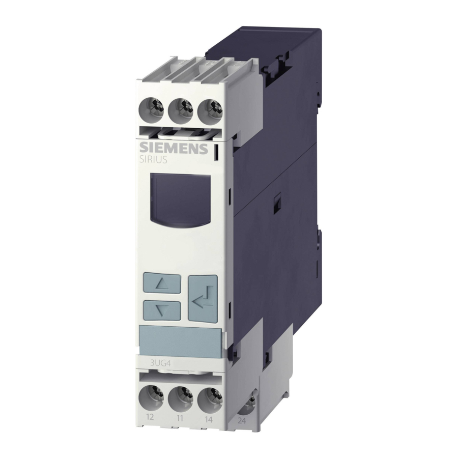
Page 173: 3Ug4621/3Ug4622 Current Monitoring Relays
Wire-break monitoring • Heating systems (electroplating plants, plastic • injection machines, paintshops) Lamps (tunnels, OP lighting, traffic lights, • signal systems, UV lamps, infrared radiators, laser lamps) 3UG4 / 3RR2 monitoring relays Manual, 05/2016, NEB927043002000/RS-AC/004…
-
Page 174: Operator Controls And Connection Terminals
You can find additional information on the connection terminals and the permissible conductor cross-sections in the Chapter «Connection methods (Page 21)». You can find information on connecting in the Chapter «Circuit diagrams (Page 182)». 3UG4 / 3RR2 monitoring relays Manual, 05/2016, NEB927043002000/RS-AC/004…
-
Page 175: Functions
Note For AC currents I > 10 A, commercially available current transformers, e.g. 4NC, can be used as accessories. You will find more information in Catalog LV10 (www.siemens.com/lowvoltage/infomaterial). 3UG4 / 3RR2 monitoring relays Manual, 05/2016, NEB927043002000/RS-AC/004…
-
Page 176
NC or NO working principle. You will find the switching states of the output relay below in the section entitled «Function diagrams» and in Chapter «Diagnostics (Page 180).» 3UG4 / 3RR2 monitoring relays Manual, 05/2016, NEB927043002000/RS-AC/004… -
Page 177
Relay switching behavior = NC (closed-circuit Relay switching behavior = NO (open-circuit principle) principle) = on = on J = Currently measured current value I = set threshold value for the current 3UG4 / 3RR2 monitoring relays Manual, 05/2016, NEB927043002000/RS-AC/004… -
Page 178
Relay switching behavior = NO (open-circuit principle) principle) I > 3 mA / 50 mA I > 3 mA / 50 mA J = Currently measured current value I = set threshold value for the current 3UG4 / 3RR2 monitoring relays Manual, 05/2016, NEB927043002000/RS-AC/004… -
Page 179: Operation
• Current overshoot • Current undershoot The up-to-date measured value is displayed permanently. The parameters are described in the Chapter «Parameters (Page 363)». Menu-based operation is described in the Chapter «Menu-based operation (Page 39)». 3UG4 / 3RR2 monitoring relays Manual, 05/2016, NEB927043002000/RS-AC/004…
-
Page 180: Diagnostics
Flashing: Delay time (ON-delay or tripping delay) running • Masked out: Relay contact 11/12 closed, relay contact 11/14 open • You will find more information about the switching behavior of the output relay in Chapter «Functions (Page 175).» 3UG4 / 3RR2 monitoring relays Manual, 05/2016, NEB927043002000/RS-AC/004…
-
Page 181: Reset
2.5 s after removal of the cause of error. If the cause of the error has not been removed, a new error message appears immediately. Alternatively, the devices can be reset by switching the rated control supply voltage on and off. 3UG4 / 3RR2 monitoring relays Manual, 05/2016, NEB927043002000/RS-AC/004…
-
Page 182: Circuit Diagrams
On the 24 to 240 V AC/DC versions of the 3UG4621/22-.AW30, terminals A2 and M (GND) are electrically separated! 7.6.2 Wiring examples (3UG46..-.AW30) Single-phase operation Three-phase operation 3UG462.-.AW30 single-phase operation 3UG462.-.AW30 three-phase operation 3UG4 / 3RR2 monitoring relays Manual, 05/2016, NEB927043002000/RS-AC/004…
-
Page 183: Wiring Examples (3Ug462.-.Aa30)
If the load to be monitored and the current monitoring relay are powered from the same system, terminal A2 is not required! The load current must always flow away through M (GND), otherwise the current monitoring relay may be destroyed! 3UG4 / 3RR2 monitoring relays Manual, 05/2016, NEB927043002000/RS-AC/004…
-
Page 184: Technical Data
Adjustable switching hysteresis for 0.1 … 250 10 … 5 000 measured current value Stored energy time at mains power cut minimum Operating voltage 24 … 240 24 … 240 rated value • 3UG4 / 3RR2 monitoring relays Manual, 05/2016, NEB927043002000/RS-AC/004…
-
Page 185
Starting time after the control supply voltage has been applied Response time maximum Relative metering precision Precision of digital display +/-1 digit Relative temperature-related measurement deviation Temperature drift per °C %/°C Relative repeat accuracy 3UG4 / 3RR2 monitoring relays Manual, 05/2016, NEB927043002000/RS-AC/004… -
Page 186
400 V at 50/60 Hz – at DC-13 – at 24 V – at 125 V – at 250 V for permanent overcurrent • maximum permissible for overcurrent duration • < 1 s maximum permissible 3UG4 / 3RR2 monitoring relays Manual, 05/2016, NEB927043002000/RS-AC/004… -
Page 187
Mechanical operating cycles as 10 000 000 operating time typical Electrical operating cycles as 100 000 operating time at AC-15 at 230 V typical Operating cycles with 3RT2 5 000 contactor maximum 3UG4 / 3RR2 monitoring relays Manual, 05/2016, NEB927043002000/RS-AC/004… -
Page 188
Distance, to be maintained, to the ranks assembly forwards • backwards • sidewards • upwards • downwards • Distance, to be maintained, conductive elements forwards • backwards • sidewards • upwards • downwards • 3UG4 / 3RR2 monitoring relays Manual, 05/2016, NEB927043002000/RS-AC/004… -
Page 189
2x (24 … 16) – solid 2x (20 … 14) 2x (24 … 16) – stranded Tightening torque N·m 0.8 … 1.2 — … with screw-type terminals • Number of change-over switches delayed switching 3UG4 / 3RR2 monitoring relays Manual, 05/2016, NEB927043002000/RS-AC/004… -
Page 190
3UG4621/3UG4622 current monitoring relays 7.7 Technical data 3UG4 / 3RR2 monitoring relays Manual, 05/2016, NEB927043002000/RS-AC/004… -
Page 191: 3Ug4625 Residual Current Monitoring Relay With 3Ul23 Transformer
Diminishing insulation caused by material wear Furnaces • • Note 3UG4625 residual current monitoring relays monitor devices and systems for their correct function. They are not suitable for personal protection or protection from fires. 3UG4 / 3RR2 monitoring relays Manual, 05/2016, NEB927043002000/RS-AC/004…
-
Page 192: Operator Controls And Connection Terminals
You can find additional information on the connection terminals and the permissible conductor cross-sections in the Chapter «Connection methods (Page 21)». You can find information on connecting in the Chapter «Circuit diagrams (Page 206)». 3UG4 / 3RR2 monitoring relays Manual, 05/2016, NEB927043002000/RS-AC/004…
-
Page 193: Functions
This current is evaluated in the monitoring relay and used to display the current residual current and to switch the output relays when the set warning threshold or the tripping threshold is overshot. 3UG4 / 3RR2 monitoring relays Manual, 05/2016, NEB927043002000/RS-AC/004…
-
Page 194
The measuring accuracy is -7.5 %/+7.5 % of the value displayed. This takes into account the measuring accuracy of monitoring relay and residual current transformer. 3UG4 / 3RR2 monitoring relays Manual, 05/2016, NEB927043002000/RS-AC/004… -
Page 195
To avoid these types of measuring errors and false tripping, we recommend to set the limit values to the minimum values listed in the following graphic, depending on the applicable primary current. 3UG4 / 3RR2 monitoring relays Manual, 05/2016, NEB927043002000/RS-AC/004… -
Page 196
In the case of extreme peak values of the residual current, the measuring accuracy suffers as a result of this principle. Due to the great difference between the peak value and the rms value, monitoring for lower limits is useful. 3UG4 / 3RR2 monitoring relays Manual, 05/2016, NEB927043002000/RS-AC/004… -
Page 197
On the display, the actual measured value and the symbol for overshoot flash. You will find the switching states of the output relays below in section «Function diagrams» and in Chapter «Diagnostics (Page 203).» 3UG4 / 3RR2 monitoring relays Manual, 05/2016, NEB927043002000/RS-AC/004… -
Page 198
These necessary accessories are described in Chapter «3UL23 residual current transformers for 3UG4625 monitoring relays (Page 333).» Note Do not ground the neutral conductor downstream of the residual current transformer as otherwise fault current monitoring functions can no longer be ensured. 3UG4 / 3RR2 monitoring relays Manual, 05/2016, NEB927043002000/RS-AC/004… -
Page 199
I▲ / I! Mem = no Init = ERR Display Memory = no; Init = ERR Relay switching behavior = NC (closed-circuit principle) I▲ / I! Mem = no Init = ERR 3UG4 / 3RR2 monitoring relays Manual, 05/2016, NEB927043002000/RS-AC/004… -
Page 200
I▲ / I! Mem = yes Init = ERR Display Memory = no; Init = OK Relay switching behavior = NO (open-circuit principle) I▲ / I! Mem = no Init = OK 3UG4 / 3RR2 monitoring relays Manual, 05/2016, NEB927043002000/RS-AC/004… -
Page 201
Relay switching behavior = NC (closed-circuit principle) I▲ / I! Mem = yes Init = OK Note The system is immediately switched off in the event of an open-circuit or short-circuit in the transformer connection cables. 3UG4 / 3RR2 monitoring relays Manual, 05/2016, NEB927043002000/RS-AC/004… -
Page 202: Operation
The 3UL23 residual current transformers used cover the entire fault current range from 0.03 to 40 A in all sizes. For more information on the technical data of 3UL23 residual current transformers see Chapter «Technical data (Page 346)». 3UG4 / 3RR2 monitoring relays Manual, 05/2016, NEB927043002000/RS-AC/004…
-
Page 203: Diagnostics
8.5.1 Indications on the display Display information The display is divided into three different areas. ① Current measured value or fault symbol ② Type of monitoring ③ Symbols of the changeover contacts 3UG4 / 3RR2 monitoring relays Manual, 05/2016, NEB927043002000/RS-AC/004…
-
Page 204
Measurement range exceeded (> 40 A) ① 0.00A Fallen below measurement range ① Open circuit (flashing) ① Short-circuit (flashing) You will find more information about the switching behavior of the output relay in Chapter «Functions (Page 193).» 3UG4 / 3RR2 monitoring relays Manual, 05/2016, NEB927043002000/RS-AC/004… -
Page 205: Reset
Alternatively, the devices can be reset by switching the rated control supply voltage on and off. Note The warning threshold is always reset by autoreset. 3UG4 / 3RR2 monitoring relays Manual, 05/2016, NEB927043002000/RS-AC/004…
-
Page 206: Circuit Diagrams
3UL23 residual current transformer is connected to terminals C1 and C2 of the monitoring relay. To avoid interference injection, which could result in incorrect measurements, these connecting lines must be routed as parallel as possible and twisted, or shielded cables must be used. 3UG4 / 3RR2 monitoring relays Manual, 05/2016, NEB927043002000/RS-AC/004…
-
Page 207: Wiring Examples
3UG4625 residual current monitoring relay with 3UL23 transformer 8.6 Circuit diagrams 8.6.2 Wiring examples ① Cable shielding recommended Image 8-1 Wiring diagram of 3UG4625 with 3UL23 3UG4 / 3RR2 monitoring relays Manual, 05/2016, NEB927043002000/RS-AC/004…
-
Page 208: Technical Data
Starting time after the control supply voltage has been 1 600 applied Response time maximum Relative metering precision Precision of digital display +/-1 digit Temperature drift per °C %/°C Relative repeat accuracy 3UG4 / 3RR2 monitoring relays Manual, 05/2016, NEB927043002000/RS-AC/004…
-
Page 209
Conductor-bound parasitic coupling BURST according to 2 kV IEC 61000-4-4 Conductor-bound parasitic coupling conductor-earth SURGE 2 kV according to IEC 61000-4-5 Conductor-bound parasitic coupling conductor-conductor 1 kV SURGE according to IEC 61000-4-5 3UG4 / 3RR2 monitoring relays Manual, 05/2016, NEB927043002000/RS-AC/004… -
Page 210
Mechanical operating cycles as operating time typical 10 000 000 Electrical operating cycles as operating time at AC-15 at 100 000 230 V typical Operating cycles with 3RT2 contactor maximum 5 000 3UG4 / 3RR2 monitoring relays Manual, 05/2016, NEB927043002000/RS-AC/004… -
Page 211
2x (20 … 14) 2x (24 … 16) – stranded 2x (20 … 14) 2x (24 … 16) Tightening torque N·m 0.8 … 1.2 — with screw-type terminals • Number of change-over switches delayed switching 3UG4 / 3RR2 monitoring relays Manual, 05/2016, NEB927043002000/RS-AC/004… -
Page 212
3UG4625 residual current monitoring relay with 3UL23 transformer 8.7 Technical data 3UG4 / 3RR2 monitoring relays Manual, 05/2016, NEB927043002000/RS-AC/004… -
Page 213: 3Ug458. Insulation Monitoring Relay
This procedure enables controlled shutdown, or correction of the fault without interrupting the power supply. 3UG4 / 3RR2 monitoring relays Manual, 05/2016, NEB927043002000/RS-AC/004…
-
Page 214
● Ungrounded, mixed DC systems and AC systems for insulation faults (e.g. AC systems with rectifiers or switched-mode power supplies) Note The use of two 3UG458 devices in a galvanically connected area (monitored area) is not permissible. ① Monitored area 3UG4 / 3RR2 monitoring relays Manual, 05/2016, NEB927043002000/RS-AC/004… -
Page 215: Application Areas
2p: Monitoring is 2-phase 2p + N: Monitoring is 2-phase + N conductor 3p: Monitoring is 3-phase 3p + N: Monitoring is 3-phase + N conductor — : Function not available Configurable 3UG4 / 3RR2 monitoring relays Manual, 05/2016, NEB927043002000/RS-AC/004…
-
Page 216: Performance Features Of The Insulation Monitoring Relays
+ 1 changeover contact, adjustable Number of thresholds ✓ ✓ — • — — ✓ 1 or 2, adjustable • Functional principle Closed-circuit principle Closed-circuit principle Open-circuit principle or closed- circuit principle, configurable 3UG4 / 3RR2 monitoring relays Manual, 05/2016, NEB927043002000/RS-AC/004…
-
Page 217
Retentive fault memory — — ✓ Open-circuit detection — — ✓ ✓: Function available — : Function not available With 3UG4983-1A upstream module Configurable 3UG4 / 3RR2 monitoring relays Manual, 05/2016, NEB927043002000/RS-AC/004… -
Page 218: 3Ug4581 Insulation Monitoring Relay
You can find additional information on the connection terminals and the permissible conductor cross-sections in the Chapter «Technical data (Page 233)». You can find information on connecting in the Chapter «Circuit diagrams (Page 227)». 3UG4 / 3RR2 monitoring relays Manual, 05/2016, NEB927043002000/RS-AC/004…
-
Page 219: Functions
The insulation resistance of the system is calculated with the help of the overlaid DC measuring voltage and the resulting current. The 3UG4581 insulation monitoring relays can be configured to the relevant application conditions and are therefore versatile in use. 3UG4 / 3RR2 monitoring relays Manual, 05/2016, NEB927043002000/RS-AC/004…
-
Page 220
If the continuously present rated system voltage is greater than 240 V, a minimum gap of 10 mm must be maintained to the next device. You will find the switching states of the output relay below in the section «Functions (Page 219)» and in Chapter «Diagnostics (Page 226)». 3UG4 / 3RR2 monitoring relays Manual, 05/2016, NEB927043002000/RS-AC/004… -
Page 221
2) Remote reset (remote button with NC function) 3) A1+ / A2- (switching the supply voltage off/on) 1) On the front (Test/Reset button) 2) A1+ / A2- (switching the supply voltage off/on) 1) Autoreset (factory setting) 3UG4 / 3RR2 monitoring relays Manual, 05/2016, NEB927043002000/RS-AC/004… -
Page 222
Without fault storage, autoreset ① Test (Y1-Y3) ② Reset (Y2-Y3) ③ Measured value ④ Hysteresis ⑤ Threshold ⑥ Green ⑦ ⑧ Yellow = Time for internal device test after applying the supply voltage 3UG4 / 3RR2 monitoring relays Manual, 05/2016, NEB927043002000/RS-AC/004… -
Page 223
With fault storage, manual RESET ① Test (Y1-Y3) ② Reset (Y2-Y3) ③ Measured value ④ Hysteresis ⑤ Threshold ⑥ Green ⑦ ⑧ Yellow = Time for internal device test after applying the supply voltage 3UG4 / 3RR2 monitoring relays Manual, 05/2016, NEB927043002000/RS-AC/004… -
Page 224: Operator Control
Chapter «Internal circuit diagrams (Page 227)» shows examples for the different monitoring modes. The parameters are defined in the Chapter «Parameters (Page 363)». Tools required The same screwdriver can be used to set the parameters as for wiring the insulation monitoring relays. 3UG4 / 3RR2 monitoring relays Manual, 05/2016, NEB927043002000/RS-AC/004…
-
Page 225
The test function can be started again at any time via the Test/Reset button on the front or via a remote test button. The graphic below shows the connection of the button for the remote test. Image 9-1 Remote test button 3UG4 / 3RR2 monitoring relays Manual, 05/2016, NEB927043002000/RS-AC/004… -
Page 226: Diagnostics
The device has tripped following an insulation fault. The fault has been stored and the insulation resistance has reverted to a value above the set threshold including hysteresis. Dependent on the fault. The switching behavior of the output relay is shown in Chapter «Functions (Page 219)». 3UG4 / 3RR2 monitoring relays Manual, 05/2016, NEB927043002000/RS-AC/004…
-
Page 227: Circuit Diagrams
3UG458. insulation monitoring relay 9.3 3UG4581 insulation monitoring relay 9.3.5 Circuit diagrams 9.3.5.1 Internal circuit diagrams Internal circuit diagram 3UG4581-1AW30 insulation monitoring relay 3UG4 / 3RR2 monitoring relays Manual, 05/2016, NEB927043002000/RS-AC/004…
-
Page 228
Measuring input L can be connected to any conductor (phase or N conductor). The rated system voltage must be U ≤ 400 V AC (50 to 60 Hz). 2-wire AC system 3-wire AC system 4-wire AC system 3UG4 / 3RR2 monitoring relays Manual, 05/2016, NEB927043002000/RS-AC/004… -
Page 229
Image 9-2 Monitoring for ground fault/insulation fault in the case of an ungrounded 2-wire IT AC system Note The maximum cable length of the control cables is 50 m or 100 pF/m. 3UG4 / 3RR2 monitoring relays Manual, 05/2016, NEB927043002000/RS-AC/004… -
Page 230
Image 9-3 Monitoring for ground fault/insulation fault in the case of an ungrounded 4-wire IT AC system Note The maximum cable length of the control cables is 50 m or 100 pF/m. 3UG4 / 3RR2 monitoring relays Manual, 05/2016, NEB927043002000/RS-AC/004… -
Page 231: Characteristics
Characteristic curves of the 3UG4581 insulation monitoring relays The characteristics below show the load limit curves of the 3UG4581 insulation monitoring relays. Image 9-4 AC load (resistive) Image 9-5 DC load (resistive) 3UG4 / 3RR2 monitoring relays Manual, 05/2016, NEB927043002000/RS-AC/004…
-
Page 232
9.3 3UG4581 insulation monitoring relay Image 9-6 Reduction factor F in the case of inductive AC load ① Operating cycles ② 250 V, resistive load ③ Switching current Image 9-7 Contact service life 3UG4 / 3RR2 monitoring relays Manual, 05/2016, NEB927043002000/RS-AC/004… -
Page 233: Technical Data
Protection class IP IP20 Ambient temperature °C -25 … +60 during operating • Item designation according to DIN EN 61346-2 Item designation according to DIN 40719 extendable after IEC 204-2 according to IEC 750 3UG4 / 3RR2 monitoring relays Manual, 05/2016, NEB927043002000/RS-AC/004…
-
Page 234
20 … 12 solid • AWG number as coded connectable conductor cross section 18 … 14 stranded • Tightening torque N·m 0.6 … 0.8 with screw-type terminals • Number of change-over switches delayed switching 3UG4 / 3RR2 monitoring relays Manual, 05/2016, NEB927043002000/RS-AC/004… -
Page 235: 3Ug4582/3Ug4583 Insulation Monitoring Relays
You can find additional information on the connection terminals and the permissible conductor cross-sections in the Chapter «Technical data (Page 265)». You can find information on connecting in the Chapter «Circuit diagrams (Page 255)». 3UG4 / 3RR2 monitoring relays Manual, 05/2016, NEB927043002000/RS-AC/004…
-
Page 236
Output relay K1 CO contact root Output relay K1 CO contact NO contact Output relay K2 CO contact NC contact Output relay K2 CO contact root Output relay K2 CO contact NO contact 3UG4 / 3RR2 monitoring relays Manual, 05/2016, NEB927043002000/RS-AC/004… -
Page 237
You can find additional information on the connection terminals and the permissible conductor cross-sections in the Chapter «Technical data (Page 265)». You can find information on connecting in the Chapter «Circuit diagrams (Page 255)». 3UG4 / 3RR2 monitoring relays Manual, 05/2016, NEB927043002000/RS-AC/004… -
Page 238: Functions
K1 responds depending on the device configuration. This adaptive measuring principle is suitable for detecting symmetrical insulation faults. 3UG4 / 3RR2 monitoring relays Manual, 05/2016, NEB927043002000/RS-AC/004…
-
Page 239
The output relays would only pick up if an insulation fault or internal device faults are detected. However, the fault «Missing supply voltage» can then no longer be detected. 3UG4 / 3RR2 monitoring relays Manual, 05/2016, NEB927043002000/RS-AC/004… -
Page 240
(Page 243)» and in the Chapter «Diagnostics (Page 253)». You will find the setting ranges and factory settings of the available parameters, and the definitions of the DIP switch positions in the Chapter «Operator control (Page 249)». 3UG4 / 3RR2 monitoring relays Manual, 05/2016, NEB927043002000/RS-AC/004… -
Page 241
2) Remote reset (remote button with NC function) 3) A1+ / A2- (switching the supply voltage off/on) 1) On the front (Test/Reset button) 2) A1+ / A2- (switching the supply voltage off/on) 1) Autoreset (factory setting) 3UG4 / 3RR2 monitoring relays Manual, 05/2016, NEB927043002000/RS-AC/004… -
Page 242
690 V AC and 1000 V DC. The upstream module is connected to terminals VS, V1+ and V1- of the insulation monitoring relay. These accessories are described in Chapter «3UG4983 upstream module for the 3UG4583 monitoring relay (Page 353)». 3UG4 / 3RR2 monitoring relays Manual, 05/2016, NEB927043002000/RS-AC/004… -
Page 243: Function Diagrams
Without fault storage, autoreset ① Test (Y1-Y3) ② Reset (Y2-Y3) ③ Measured value ④ Hysteresis ⑤ Threshold ⑥ Green ⑦ ⑧ Yellow = Time for internal device test after applying the supply voltage 3UG4 / 3RR2 monitoring relays Manual, 05/2016, NEB927043002000/RS-AC/004…
-
Page 244
With fault storage, manual RESET ① Test (Y1-Y3) ② Reset (Y2-Y3) ③ Measured value ④ Hysteresis ⑤ Threshold ⑥ Green ⑦ ⑧ Yellow = Time for internal device test after applying the supply voltage 3UG4 / 3RR2 monitoring relays Manual, 05/2016, NEB927043002000/RS-AC/004… -
Page 245
With fault storage, manual RESET, 1 x 2 changeover contacts, shutdown principle) ① Test (Y1-Y3) ② Reset (Y2-Y3) ③ Measured value ④ Hysteresis ⑤ Threshold ⑥ Green ⑦ ⑧ Yellow = Time for internal device test after applying the supply voltage 3UG4 / 3RR2 monitoring relays Manual, 05/2016, NEB927043002000/RS-AC/004… -
Page 246
With fault storage, manual RESET, 1 x 2 changeover contacts, shutdown principle) ① Test (Y1-Y3) ② Reset (Y2-Y3) ③ Measured value ④ Hysteresis ⑤ Threshold ⑥ Green ⑦ ⑧ Yellow = Time for internal device test after applying the supply voltage 3UG4 / 3RR2 monitoring relays Manual, 05/2016, NEB927043002000/RS-AC/004… -
Page 247
① Test (Y1-Y3) ② Reset (Y2-Y3) ③ Measured value ④ Hysteresis ⑤ Warning ⑥ Shutdown ⑦ Green ⑧ ⑨ Yellow = Time for internal device test after applying the supply voltage 3UG4 / 3RR2 monitoring relays Manual, 05/2016, NEB927043002000/RS-AC/004… -
Page 248
① Test (Y1-Y3) ② Reset (Y2-Y3) ③ Measured value ④ Hysteresis ⑤ Warning ⑥ Shutdown ⑦ Green ⑧ ⑨ Yellow = Time for internal device test after applying the supply voltage 3UG4 / 3RR2 monitoring relays Manual, 05/2016, NEB927043002000/RS-AC/004… -
Page 249: Operator Control
The threshold is derived from the sum of the two set values. If, for example, threshold R.1-value is set to 70 and threshold R.2-value is set to 8 on the 3UG4582, threshold R corresponds to 78 kΩ. 3UG4 / 3RR2 monitoring relays Manual, 05/2016, NEB927043002000/RS-AC/004…
-
Page 250
Functional principle of fault storage output relays K1 and K2 ON ↑ 2 x 1 changeover contacts Activated Activated Closed-circuit principle NC 1 x 2 changeover contacts Deactivated Deactivated Open-circuit principle NO 3UG4 / 3RR2 monitoring relays Manual, 05/2016, NEB927043002000/RS-AC/004… -
Page 251
Chapter «Wiring examples (Page 256)» shows the examples for the different monitoring modes. The parameters are defined in the Chapter «Parameters (Page 363)». Tools required The same screwdriver can be used to set the parameters as for wiring the insulation monitoring relays. 3UG4 / 3RR2 monitoring relays Manual, 05/2016, NEB927043002000/RS-AC/004… -
Page 252
The test function can be started again at any time via the Test/Reset button on the front or via a remote test button. The graphic below shows the connection of the button for the remote test. Image 9-8 Remote test button 3UG4 / 3RR2 monitoring relays Manual, 05/2016, NEB927043002000/RS-AC/004… -
Page 253: Diagnostics
Internal fault On the 3UG4582: On the 3UG4582: Off • • On the 3UG4583: Dependent • On the 3UG4583: on the configuration • Dependent on the configuration 3UG4 / 3RR2 monitoring relays Manual, 05/2016, NEB927043002000/RS-AC/004…
-
Page 254
The device has tripped following an insulation fault. The fault has been stored and the insulation resistance has reverted to a value above the set threshold including hysteresis. Dependent on the fault. The switching behavior of the output relay is shown in Chapter «Functions (Page 238)». 3UG4 / 3RR2 monitoring relays Manual, 05/2016, NEB927043002000/RS-AC/004… -
Page 255: Circuit Diagrams
3UG458. insulation monitoring relay 9.4 3UG4582/3UG4583 insulation monitoring relays 9.4.5 Circuit diagrams 9.4.5.1 Internal circuit diagrams Internal circuit diagrams 3UG4582-1AW30 / 3UG4583-1CW30 3UG4582-1AW30 insulation monitoring relay 3UG4583-1CW30 insulation monitoring relay 3UG4 / 3RR2 monitoring relays Manual, 05/2016, NEB927043002000/RS-AC/004…
-
Page 256: Wiring Examples
2-wire AC system / 2-wire DC system 2-wire AC system 2-wire DC system 3-wire AC system / 3-wire DC system 3-wire AC system 3-wire DC system 4-wire AC system 4-wire AC system 3UG4 / 3RR2 monitoring relays Manual, 05/2016, NEB927043002000/RS-AC/004…
-
Page 257
④ Loads Image 9-9 Monitoring for ground fault/insulation fault with different load circuits Note The maximum cable length of the control cables is 50 m or 100 pF/m. 3UG4 / 3RR2 monitoring relays Manual, 05/2016, NEB927043002000/RS-AC/004… -
Page 258
1A upstream module must be used to monitor systems with higher voltages. 2-wire AC system / 2-wire DC system 2-wire AC system 2-wire DC system 3-wire AC system/3-wire DC system 3-wire AC system 3-wire DC system 4-wire AC system 4-wire AC system 3UG4 / 3RR2 monitoring relays Manual, 05/2016, NEB927043002000/RS-AC/004… -
Page 259
Loads Image 9-10 Monitoring for ground fault/insulation fault in the case of an ungrounded 4-wire AC system Note The maximum cable length of the control cables is 50 m or 100 pF/m. 3UG4 / 3RR2 monitoring relays Manual, 05/2016, NEB927043002000/RS-AC/004… -
Page 260
④ Loads Image 9-11 Monitoring for ground fault/insulation fault with different load circuits Note The maximum cable length of the control cables is 50 m or 100 pF/m. 3UG4 / 3RR2 monitoring relays Manual, 05/2016, NEB927043002000/RS-AC/004… -
Page 261: Characteristics
Characteristics Characteristics of the 3UG4582 insulation monitoring relays The characteristics below show the load limit curves of the 3UG4582 insulation monitoring relays. Image 9-12 AC load (resistive) Image 9-13 DC load (resistive) 3UG4 / 3RR2 monitoring relays Manual, 05/2016, NEB927043002000/RS-AC/004…
-
Page 262
9.4 3UG4582/3UG4583 insulation monitoring relays Image 9-14 Reduction factor F in the case of inductive AC load ① Operating cycles ② 250 V, resistive load ③ Switching current Image 9-15 Contact service life 3UG4 / 3RR2 monitoring relays Manual, 05/2016, NEB927043002000/RS-AC/004… -
Page 263
9.4 3UG4582/3UG4583 insulation monitoring relays Characteristics of the 3UG4583 insulation monitoring relays The characteristics below show the load limit curves of the 3UG4583 insulation monitoring relays. Image 9-16 AC load (resistive) Image 9-17 DC load (resistive) 3UG4 / 3RR2 monitoring relays Manual, 05/2016, NEB927043002000/RS-AC/004… -
Page 264
9.4 3UG4582/3UG4583 insulation monitoring relays Image 9-18 Reduction factor F in the case of inductive AC load ① Operating cycles ② 250 V, resistive load ③ Switching current Image 9-19 Contact service life 3UG4 / 3RR2 monitoring relays Manual, 05/2016, NEB927043002000/RS-AC/004… -
Page 265: Technical Data
DC • 24 … 240 – rated value at 50 Hz at AC • 24 … 240 – rated value at 60 Hz at AC • 24 … 240 – rated value 3UG4 / 3RR2 monitoring relays Manual, 05/2016, NEB927043002000/RS-AC/004…
-
Page 266
Protection class IP IP20 Ambient temperature °C -25 … +60 during operating • Item designation according to DIN EN 61346-2 • according to DIN 40719 extendable after • IEC 204-2 according to IEC 750 3UG4 / 3RR2 monitoring relays Manual, 05/2016, NEB927043002000/RS-AC/004… -
Page 267
Distance, to be maintained, conductive elements forwards • backwards • sidewards • upwards • downwards • Distance, to be maintained, to earthed part forwards • backwards • sidewards • upwards • downwards • 3UG4 / 3RR2 monitoring relays Manual, 05/2016, NEB927043002000/RS-AC/004… -
Page 268
AWG number as coded connectable conductor cross section 20 … 12 … solid • 18 … 14 stranded • Tightening torque N·m 0.6 … 0.8 with screw-type terminals • Number of change-over switches delayed switching 3UG4 / 3RR2 monitoring relays Manual, 05/2016, NEB927043002000/RS-AC/004… -
Page 269: 3Ug4583
Protection class IP IP20 Ambient temperature °C -25 … +60 during operating • Item designation according to DIN EN 61346-2 • according to DIN 40719 extendable after IEC 204-2 according to • IEC 750 3UG4 / 3RR2 monitoring relays Manual, 05/2016, NEB927043002000/RS-AC/004…
-
Page 270
AWG number as coded connectable conductor cross section 20 … 12 solid • 18 … 14 stranded • Tightening torque N·m 0.6 … 0.8 with screw-type terminals • Number of change-over switches delayed switching 3UG4 / 3RR2 monitoring relays Manual, 05/2016, NEB927043002000/RS-AC/004… -
Page 271: 3Ug463. Voltage Monitoring Relay
System protection against destruction caused by supply overvoltages • Energy supply to the line • Machine switch-on when a defined voltage is reached • Threshold switch for analog signals from 0.1 to 10 V • 3UG4 / 3RR2 monitoring relays Manual, 05/2016, NEB927043002000/RS-AC/004…
-
Page 272: 3Ug4631 / 3Ug4632 Voltage Monitoring Relay
You can find additional information on the connection terminals and the permissible conductor cross-sections in the Chapter «Connection methods (Page 21)». You can find information on connecting in the Chapter «Circuit diagrams (Page 281)». 3UG4 / 3RR2 monitoring relays Manual, 05/2016, NEB927043002000/RS-AC/004…
-
Page 273: Functions
0.0 V and shows a symbol for voltage overshoot monitoring, voltage undershoot monitoring, or range monitoring. You will find the switching states of the output relay below in the section entitled «Function diagrams» and in Chapter «Diagnostics (Page 279).» 3UG4 / 3RR2 monitoring relays Manual, 05/2016, NEB927043002000/RS-AC/004…
-
Page 274
10.2 3UG4631 / 3UG4632 voltage monitoring relay Function diagrams 3UG4631 / 3UG4632 Display Memory = no Memory = no Relay switching behavior = NC Relay switching behavior = NO (closed-circuit principle) (open-circuit principle) 3UG4 / 3RR2 monitoring relays Manual, 05/2016, NEB927043002000/RS-AC/004… -
Page 275: 3Ug4633 Voltage Monitoring Relay
You can find additional information on the connection terminals and the permissible conductor cross-sections in the Chapter «Connection methods (Page 21)». You can find information on connecting in the Chapter «Circuit diagrams (Page 281)». 3UG4 / 3RR2 monitoring relays Manual, 05/2016, NEB927043002000/RS-AC/004…
-
Page 276: Functions
You will find the switching states of the output relay below in the section entitled «Function diagrams» and in Chapter «Diagnostics (Page 279).» 3UG4 / 3RR2 monitoring relays Manual, 05/2016, NEB927043002000/RS-AC/004…
-
Page 277
3UG463. voltage monitoring relay 10.3 3UG4633 voltage monitoring relay Function diagrams 3UG4633 Display Memory = no Memory = no Relay switching behavior = NC Relay switching behavior = NO (closed-circuit principle) (open-circuit principle) 3UG4 / 3RR2 monitoring relays Manual, 05/2016, NEB927043002000/RS-AC/004… -
Page 278: Operation
• Voltage overshoot • Voltage undershoot The up-to-date measured value is displayed permanently. The parameters are described in Chapter «Parameters (Page 363).» Menu-based operation is described in Chapter «Menu-based operation (Page 39).» 3UG4 / 3RR2 monitoring relays Manual, 05/2016, NEB927043002000/RS-AC/004…
-
Page 279: Diagnostics
Masked out: Relay contact 11/12 closed, relay contact 11/14 open • You will find more information about the switching behavior of the output relay in Chapter «Functions (Page 273)» (3UG4631 / 3UG4632) and «Functions (Page 276)» (3UG4633). 3UG4 / 3RR2 monitoring relays Manual, 05/2016, NEB927043002000/RS-AC/004…
-
Page 280: Reset
2.5 s after removal of the cause of error. If the cause of the error has not been removed, a new error message appears immediately. Alternatively, the devices can be reset by switching the rated control supply voltage on and off. 3UG4 / 3RR2 monitoring relays Manual, 05/2016, NEB927043002000/RS-AC/004…
-
Page 281: Circuit Diagrams
On the 24 V AC/DC versions of the 3UG4631-.AA30 and 3UG4632-.AA30, terminals A2 and M (GND) are electrically connected in the device! On the 24 to 240 V AC/DC versions of the 3UG4631-.AW30 and 3UG4632-.AW30, terminals A2 and M (GND) are electrically separated! 3UG4 / 3RR2 monitoring relays Manual, 05/2016, NEB927043002000/RS-AC/004…
-
Page 282: Wiring Examples
3UG463. voltage monitoring relay 10.6 Circuit diagrams 10.6.2 Wiring examples 3UG4631-.AA30 / 3UG4632-.AA30 Image 10-1 3UG4631-.AA30 / 3UG4632-.AA30 3UG4631-.AW30 / 3UG4632-.AW30 Image 10-2 3UG4631-.AW30 / 3UG4632-.AW30 3UG4633 Image 10-3 3UG4633 3UG4 / 3RR2 monitoring relays Manual, 05/2016, NEB927043002000/RS-AC/004…
-
Page 283: Technical Data
10 … 600 17 … 275 voltage range Adjustable response delay time — — 0.1 … 20 — 0.1 … 20 when • starting 0.1 … 20 with lower • or upper limit violation 3UG4 / 3RR2 monitoring relays Manual, 05/2016, NEB927043002000/RS-AC/004…
-
Page 284
• recognition DC undervoltage • recognition of 1 phase undervoltage • recognition of 3 phases undervoltage • recognition DC reset external • self-reset • open-circuit or • closed-circuit current principle 3UG4 / 3RR2 monitoring relays Manual, 05/2016, NEB927043002000/RS-AC/004… -
Page 285
0.85 … 1.15 0.85 … 1.1 0.85 … 1.15 0.85 … 1.1 at 60 Hz for • 0.85 … 1.15 0.85 … 1.1 0.85 … 1.15 0.85 … 1.1 for DC • 3UG4 / 3RR2 monitoring relays Manual, 05/2016, NEB927043002000/RS-AC/004… -
Page 286
SURGE according to IEC 61000-4-5 Conductor-bound 1 kV parasitic coupling conductor-conductor SURGE according to IEC 61000-4-5 Electrostatic 6 kV contact discharge / 8 kV air discharge discharge according to IEC 61000-4-2 3UG4 / 3RR2 monitoring relays Manual, 05/2016, NEB927043002000/RS-AC/004… -
Page 287
Mechanical operating 10 000 000 cycles as operating time typical Electrical operating 100 000 cycles as operating time at AC-15 at 230 V typical Operating cycles 5 000 with 3RT2 contactor maximum 3UG4 / 3RR2 monitoring relays Manual, 05/2016, NEB927043002000/RS-AC/004… -
Page 288
2x (24 … 16) – solid 2x (20 … 14) 2x (24 … 16) – stranded Tightening torque N·m 1.2 … 0.8 — … with screw-type terminals • Number of change-over switches delayed switching 3UG4 / 3RR2 monitoring relays Manual, 05/2016, NEB927043002000/RS-AC/004… -
Page 289: 3Ug4641 Cos Phi And Active Current Monitoring Relay
• Conveyor belt • Surface grinding machine • Breaking mill • Milling machine • Car wash • Lifting platform • Screw conveyor • Crane • Turning machine • Infrared heating system • 3UG4 / 3RR2 monitoring relays Manual, 05/2016, NEB927043002000/RS-AC/004…
-
Page 290: Operator Controls And Connection Terminals
You can find additional information on the connection terminals and the permissible conductor cross-sections in the Chapter «Connection methods (Page 21)». You can find information on connecting in the Chapter «Circuit diagrams (Page 299)». 3UG4 / 3RR2 monitoring relays Manual, 05/2016, NEB927043002000/RS-AC/004…
-
Page 291: Functions
Note In the case of active currents I > 10 A, commercially available current transformers, e.g. 4NC, can be used as accessories. You will find more information in Catalog LV10 (www.siemens.com/lowvoltage/infomaterial). 3UG4 / 3RR2 monitoring relays Manual, 05/2016, NEB927043002000/RS-AC/004…
-
Page 292
On the display, the current measuring value and the symbol for undershoot or overshoot flash. You will find the switching states of the output relays below in section «Function diagrams» and in Chapter «Diagnostics (Page 297).» 3UG4 / 3RR2 monitoring relays Manual, 05/2016, NEB927043002000/RS-AC/004… -
Page 293
Memory = no Memory = no Relay switching behavior = NC (closed-circuit Relay switching behavior = NO (open-circuit principle) principle) J = currently set current value I = set threshold value for the current 3UG4 / 3RR2 monitoring relays Manual, 05/2016, NEB927043002000/RS-AC/004… -
Page 294
Memory = no Memory = no Relay switching behavior = NC (closed-circuit Relay switching behavior = NO (open-circuit principle) principle) J = currently set current value I = set threshold value for the current 3UG4 / 3RR2 monitoring relays Manual, 05/2016, NEB927043002000/RS-AC/004… -
Page 295
Relay switching behavior = NC (closed-circuit Relay switching behavior = NO (open-circuit principle) principle) cos φ = currently set value for cos φ PF = power factor = set threshold for cos φ 3UG4 / 3RR2 monitoring relays Manual, 05/2016, NEB927043002000/RS-AC/004… -
Page 296: Operation
The monitoring mode «Overshoot» or «Undershoot» is defined with the setting OFF at the threshold for undershoot or overshoot. The parameters are described in Chapter «Parameters (Page 363).» Menu-based operation is described in Chapter «Menu-based operation (Page 39).» 3UG4 / 3RR2 monitoring relays Manual, 05/2016, NEB927043002000/RS-AC/004…
-
Page 297: Diagnostics
Flashing: Delay time (ON-delay or tripping delay) running • Masked out: Relay contact 21/22 closed, relay contact 21/24 open • You will find more information about the switching behavior of the output relay in Chapter «Functions (Page 291).» 3UG4 / 3RR2 monitoring relays Manual, 05/2016, NEB927043002000/RS-AC/004…
-
Page 298: Reset
2.5 s after removal of the cause of error. If the cause of the error has not been removed, a new error message appears immediately. Alternatively, the devices can be reset by switching the rated control supply voltage on and off. 3UG4 / 3RR2 monitoring relays Manual, 05/2016, NEB927043002000/RS-AC/004…
-
Page 299: Circuit Diagrams
3UG4641 cos phi and active current monitoring relay 11.6 Circuit diagrams 11.6 Circuit diagrams 11.6.1 Internal circuit diagrams Internal circuit diagrams 3UG4641 3UG4641 cos phi and active current monitoring relay 3UG4 / 3RR2 monitoring relays Manual, 05/2016, NEB927043002000/RS-AC/004…
-
Page 300: Wiring Examples
Cos phi and active current monitoring for single-phase motors Cos phi and active current monitoring for three-phase motors Cos phi and active current monitoring for Cos phi and active current monitoring for three-phase motors three-phase motors (with neutral conductor) 3UG4 / 3RR2 monitoring relays Manual, 05/2016, NEB927043002000/RS-AC/004…
-
Page 301
Cos phi and active current monitoring for three-phase motors with transformers for currents Cos phi and active current monitoring for Cos phi and active current monitoring for three-phase motors with three-phase motors with transformers for currents transformer for currents (with neutral conductor) 3UG4 / 3RR2 monitoring relays Manual, 05/2016, NEB927043002000/RS-AC/004… -
Page 302: Technical Data
• Adjustable switching hysteresis for measured current 0.1 … 2 value Stored energy time at mains power cut minimum Operating voltage 90 … 690 rated value • 3UG4 / 3RR2 monitoring relays Manual, 05/2016, NEB927043002000/RS-AC/004…
-
Page 303
1 … 6 Hz: 15 mm, 6 … 500 Hz: 2g IEC 60068-2-6 Resistance against shock according to sinusoidal half-wave 15g / 11 ms IEC 60068-2-27 Installation altitude at a height over sea level 2 000 maximum 3UG4 / 3RR2 monitoring relays Manual, 05/2016, NEB927043002000/RS-AC/004… -
Page 304
Mechanical operating cycles as operating time 10 000 000 typical Electrical operating cycles as operating time at 100 000 AC-15 at 230 V typical Operating cycles with 3RT2 contactor maximum 5 000 3UG4 / 3RR2 monitoring relays Manual, 05/2016, NEB927043002000/RS-AC/004… -
Page 305
• Distance, to be maintained, conductive elements forwards • backwards • sidewards • upwards • downwards • Type of mounting snap-on mounting Product function removable terminal for auxiliary and control circuit 3UG4 / 3RR2 monitoring relays Manual, 05/2016, NEB927043002000/RS-AC/004… -
Page 306
2x (24 … 16) – solid 2x (20 … 14) 2x (24 … 16) – stranded Tightening torque N·m 1.2 … 0.8 — … with screw-type terminals • Number of change-over switches delayed switching 3UG4 / 3RR2 monitoring relays Manual, 05/2016, NEB927043002000/RS-AC/004… -
Page 307: 3Ug4651 Speed Monitoring Relay
The speed monitoring relays can also be used for all functions where a continuous pulse signal is to be monitored (e.g. belt travel monitoring, completeness check, pass monitoring, or cycle time monitoring). 3UG4 / 3RR2 monitoring relays Manual, 05/2016, NEB927043002000/RS-AC/004…
-
Page 308: Operator Controls And Connection Terminals
You can find additional information on the connection terminals and the permissible conductor cross-sections in the Chapter «Connection methods (Page 21)». You can find information on connecting in the Chapter «Circuit diagrams (Page 315)». 3UG4 / 3RR2 monitoring relays Manual, 05/2016, NEB927043002000/RS-AC/004…
-
Page 309: Functions
5 ms. A pause is detected when the voltage level < 1 V. A pulse requires a minimum value of 4.5 V. Alternatively, a two-wire NAMUR sensor supplied from terminal 8V2, or a mechanical contact, can be connected at terminal IN2. 3UG4 / 3RR2 monitoring relays Manual, 05/2016, NEB927043002000/RS-AC/004…
-
Page 310
ON-delay time (onDel) and the drive (with a second contact, for example) be started. You will find the switching states of the output relay below in the section entitled «Function diagrams» and in Chapter «Diagnostics (Page 313).» 3UG4 / 3RR2 monitoring relays Manual, 05/2016, NEB927043002000/RS-AC/004… -
Page 311
= set threshold for the speed Note The relay control for the open-circuit principle NO is inverted to the represented function diagrams in the closed-circuit principle NC after application of the rated control supply voltage U 3UG4 / 3RR2 monitoring relays Manual, 05/2016, NEB927043002000/RS-AC/004… -
Page 312: Operation
The monitoring mode «Overshoot» or «Undershoot» is defined with the setting OFF at the threshold for undershoot or overshoot. The parameters are described in Chapter «Parameters (Page 363).» Menu-based operation is described in Chapter «Menu-based operation (Page 39).» 3UG4 / 3RR2 monitoring relays Manual, 05/2016, NEB927043002000/RS-AC/004…
-
Page 313: Diagnostics
Flashing: Delay time (ON-delay or tripping delay) running • Masked out: Relay contact 11/12 closed, relay contact 11/14 open • You will find more information about the switching behavior of the output relay in Chapter «Functions (Page 309).» 3UG4 / 3RR2 monitoring relays Manual, 05/2016, NEB927043002000/RS-AC/004…
-
Page 314: Reset
2.5 s after removal of the cause of error. If the cause of the error has not been removed, a new error message appears immediately. Alternatively, the devices can be reset by switching the rated control supply voltage on and off. 3UG4 / 3RR2 monitoring relays Manual, 05/2016, NEB927043002000/RS-AC/004…
-
Page 315: Circuit Diagrams
On the 24 V AC/DC versions of the 3UG4651-.AA30, terminals A1 / A2 and 0V / 24V are electrically connected in the device! On the 24 to 240 V AC / DC versions of the 3UG4651-.AW30, terminals A1 / A2 and 0V / 24V are electrically separated! 3UG4 / 3RR2 monitoring relays Manual, 05/2016, NEB927043002000/RS-AC/004…
-
Page 316: Wiring Examples
3UG4651 speed monitoring relay 12.6 Circuit diagrams 12.6.2 Wiring examples Speed monitoring relays without Enable input Speed monitoring relays with Enable input 3UG4 / 3RR2 monitoring relays Manual, 05/2016, NEB927043002000/RS-AC/004…
-
Page 317: Technical Data
Input current at the digital input 1 maximum Pulse duration minimum Pulse interval minimum Number of sensor signals per revolution 1 … 10 Switching hysteresis for rotational speed 1/min 0 … 99.9 3UG4 / 3RR2 monitoring relays Manual, 05/2016, NEB927043002000/RS-AC/004…
-
Page 318
– delayed switching – non-delayed Response time maximum Stored energy time at mains power cut minimum ms Relative metering precision Precision of digital display +/- 1 Digit Relative repeat accuracy 3UG4 / 3RR2 monitoring relays Manual, 05/2016, NEB927043002000/RS-AC/004… -
Page 319
Conductor-bound parasitic coupling BURST 2 kV according to IEC 61000-4-4 Conductor-bound parasitic coupling conductor-earth 2 kV SURGE according to IEC 61000-4-5 Conductor-bound parasitic coupling conductor- 1 kV conductor SURGE according to IEC 61000-4-5 3UG4 / 3RR2 monitoring relays Manual, 05/2016, NEB927043002000/RS-AC/004… -
Page 320
AC-15 at 230 V typical Operating cycles with 3RT2 contactor maximum 5 000 Acceptability for application safety-related circuits Category according to EN 954-1 none safety Integrated Level according to IEC 61508 none 3UG4 / 3RR2 monitoring relays Manual, 05/2016, NEB927043002000/RS-AC/004… -
Page 321
Distance, to be maintained, to the ranks assembly forwards • backwards • sidewards • upwards • downwards • Distance, to be maintained, conductive elements forwards • backwards • sidewards • upwards • downwards • 3UG4 / 3RR2 monitoring relays Manual, 05/2016, NEB927043002000/RS-AC/004… -
Page 322
– stranded Tightening torque N·m 0.8 … 1.2 — … with screw-type terminals • Number of NO contacts delayed switching Number of NC contacts delayed switching Number of change-over switches delayed switching 3UG4 / 3RR2 monitoring relays Manual, 05/2016, NEB927043002000/RS-AC/004… -
Page 323: Accessories
Siemens also offers a sealable membrane (3TK2820-0AA00) for securing the current monitoring relays with analog setting. The sealable membrane is fixed to the front of the device and secures the rotary buttons and sliding switches against unintentional tampering.
-
Page 324: Terminal Support For Stand-Alone Assembly
3RB3 solid-state overload relay. Table 13- 2 Stand-alone assembly of the 3RR2 current monitoring relay Size Connection system Terminal support for stand-alone assembly Screw-type 3RU2916-3AA01 Spring-loaded 3RU2916-3AC01 Screw-type 3RU2926-3AA01 Spring-loaded 3RU2926-3AC01 Screw-type 3RU2936-3AA01 3UG4 / 3RR2 monitoring relays Manual, 05/2016, NEB927043002000/RS-AC/004…
-
Page 325
Insert the contacts (a) into the central opening of the main terminals on the terminal support, with the contacts flush to the right. Make sure that the guide tabs are inserted into the designated slots on the terminal support. 3UG4 / 3RR2 monitoring relays Manual, 05/2016, NEB927043002000/RS-AC/004… -
Page 326
Position the screwdriver on the terminal support as shown in the figure. Carefully dislodge the current monitoring relay from the contactor. Pull the current monitoring relay toward you and away from the terminal support. 3UG4 / 3RR2 monitoring relays Manual, 05/2016, NEB927043002000/RS-AC/004… -
Page 327: Accessories For 3Ug4 Monitoring Relays
The sealable cover can be used to secure the actuators (rotary buttons, sliding switches, and keys) of the monitoring relays against unauthorized or unintentional manipulation. Siemens also offers a sealable membrane (3TK2820-0AA00) for securing the monitoring relays with analog setting. The sealable membrane is affixed to the front of the device and secures rotary buttons and sliding switches against unintentional manipulation.
-
Page 328: Push-In Lugs
Accessories 13.2 Accessories for 3UG4 monitoring relays 13.2.2 Push-in lugs Description The 3RP1903 push-in lugs are available for the monitoring relays. With the help of the push-in lugs, the monitoring relays can be secured with screws on a level surface (e.g. a wall). Two push-in lugs are required per device.
-
Page 329: Probes For The 3Ug4501 Monitoring Relay
Accessories 13.2 Accessories for 3UG4 monitoring relays 13.2.3 Probes for the 3UG4501 monitoring relay 3UG3207-3A three-pole wire electrode The 3UG3207-3A three-pole wire electrode can be used for two-point filling level controls in an insulating tank. In addition to the common reference electrode there is one electrode for the min.
-
Page 330
Accessories 13.2 Accessories for 3UG4 monitoring relays 3UG3207-2B two-pole bow electrode Because of the small space requirement on side installation, the 3UG3207-2B two-pole bow electrode for leakage monitoring and level monitoring can be used in small vessels and tubes. The probe can also be used to warn of the ingress of water into a casing. -
Page 331
Accessories 13.2 Accessories for 3UG4 monitoring relays Technical data Table 13- 9 Technical data — Probes for the 3UG4501 monitoring relay Order number 3UG3207-3A 3UG3207-2A 3UG3207-2B 3UG3207-1B 3UG3207-1C Three-pole Two-pole Two-pole Single-pole Single-pole Length — — — Insulation (Teflon —… -
Page 332: Summation Current Transformer For The 3Ug4624 Monitoring Relay
Accessories 13.2 Accessories for 3UG4 monitoring relays 13.2.4 Summation current transformer for the 3UG4624 monitoring relay Description The 3UL22 summation current transformers acquire residual current in machines and plants. Together with the 3UG4624 residual current monitoring relay or the motor management and control unit SIMOCODE 3UF, residual current monitoring and ground-fault monitoring are possible.
-
Page 333: 3Ul23 Residual Current Transformers For 3Ug4625 Monitoring Relays
This type of fault current can be detected by type A transformers in accordance with DIN VDE 0100-530, such as 3UL23 residual current transformers. Note 3UG4.25 residual current monitoring relays are only suitable for use with 3UL23 residual current transformers. 3UG4 / 3RR2 monitoring relays Manual, 05/2016, NEB927043002000/RS-AC/004…
-
Page 334
13.2 Accessories for 3UG4 monitoring relays ① Suitable FI type ② Circuit ③ Load current ④ Fault current Image 13-7 Possible fault current forms and suitable residual current devices More information is available on the Internet (www.siemens.com/industrial-controls/support). 3UG4 / 3RR2 monitoring relays Manual, 05/2016, NEB927043002000/RS-AC/004… -
Page 335: Installation Specifications
Accessories 13.2 Accessories for 3UG4 monitoring relays 13.2.5.2 Installation specifications Note Please ensure strict adherence to the installation specifications for live cables. WARNING Open-circuit voltage may result in death, serious injury or material damage The current transformer output is a constant current power supply. In accordance with U = R * I, the output voltage increases with an increasing resistance.
-
Page 336
Accessories 13.2 Accessories for 3UG4 monitoring relays All live cables must be routed as close to the center of the transformer as possible. Any neutral conductor must be routed through the transformer. Grounded protective conductors must not be routed through the transformer or need to be routed through the transformer in both directions. -
Page 337
Accessories 13.2 Accessories for 3UG4 monitoring relays Route power cables around the residual current transformer in a straight line and ensure the area corresponds at minimum to the internal transformer diameter. X > ∅ residual current transformer The internal transformer diameter must be at minimum twice the size of the power cable bundle diameter. -
Page 338
Accessories 13.2 Accessories for 3UG4 monitoring relays Transformer connection Transformer connecting cables must be twisted and not routed in parallel to live cables to protect from emitted interference. Keep the length of the connecting cables to a minimum. The resistance at the transformer connecting cable must not exceed 5 Ω to ensure correct fault current monitoring. -
Page 339: Potential For Optimization
Accessories 13.2 Accessories for 3UG4 monitoring relays 13.2.5.3 Potential for optimization Potential for optimization in the event of extremely high currents, false tripping due to high starting currents or in environments with high EMC interference 1. Extend the ON-delay time to fade out fault currents measured during motor startup.
-
Page 340
Accessories 13.2 Accessories for 3UG4 monitoring relays b) A solid shield sleeve, e.g. turned from a normal, low-carbon tool steel must be precisely in contact with the internal ring of the residual current transformer. The wall thickness of the sleeve must be 1 mm at minimum, the length of the sleeve (L) must correspond to the internal diameter of the transformer used. -
Page 341: Installation Faults
Accessories 13.2 Accessories for 3UG4 monitoring relays 13.2.5.4 Installation faults For reasons of clarity, the representations show only the residual current transformer with the currents passing through it rather than the complete residual current monitoring unit and residual current transformer. If the vectorial sum of the currents passing through the residual…
-
Page 342
Accessories 13.2 Accessories for 3UG4 monitoring relays Mixing up conductors In a network with several loads there is the risk that active conductors of loads that are to be separately monitored for fault currents can get mixed up. This fault leads to false tripping as the inflowing and outflowing currents are not always exactly the same strength, even if the loads are identical. -
Page 343: Internal Circuit Diagram
Accessories 13.2 Accessories for 3UG4 monitoring relays Routing contrary to the current flow To be able to form the vectorial sum of currents to and from a load correctly, all active conductors must be routed through the residual current transformer from the same direction.
-
Page 344: Installing
Accessories 13.2 Accessories for 3UG4 monitoring relays 13.2.5.6 Installing Wall mounting procedure Step Instructions Figure 1 / 2 Insert the fixing lugs into the designated openings in the unit until they reach the stop. Place the device against the wall surface prepared for establishing a screw connection.
-
Page 345
Accessories 13.2 Accessories for 3UG4 monitoring relays Mounting onto standard rail Requirement: At the installation location, a horizontal 35-mm wide mounting rail in accordance with DIN EN 60715 has been properly secured. Rail mounting is possible with residual current transformers with bushing opening diameters of up to ∅… -
Page 346: Technical Data
Accessories 13.2 Accessories for 3UG4 monitoring relays 13.2.5.7 Technical data 3UL2302/3UL2303/3UL2304 residual current transformers for fault current monitoring 3UL2302-1A 3UL2303-1A 3UL2304-1A Product equipment touch-protection Height Width 124.5 Depth 75.5 Ambient temperature °C -25 … +60 during operating • Type of mounting…
-
Page 347
Accessories 13.2 Accessories for 3UG4 monitoring relays 3UL2305/3UL2306/3UL2307 residual current transformers for fault current monitoring 3UL2305-1A 3UL2306-1A 3UL2307-1A Product equipment touch-protection Height Width Depth 207.5 Ambient temperature °C -25 … +60 during operating • Type of mounting screw fixing Diameter of the feedthrough Conductor cross section that can be mm²… -
Page 348: Dimension Drawings
Accessories 13.2 Accessories for 3UG4 monitoring relays 13.2.5.8 Dimension drawings 3UL23 residual current transformer Image 13-9 3UL2302-1A 3UG4 / 3RR2 monitoring relays Manual, 05/2016, NEB927043002000/RS-AC/004…
-
Page 349
Accessories 13.2 Accessories for 3UG4 monitoring relays Image 13-10 3UL2303-1A Image 13-11 3UL2304-1A 3UG4 / 3RR2 monitoring relays Manual, 05/2016, NEB927043002000/RS-AC/004… -
Page 350
Accessories 13.2 Accessories for 3UG4 monitoring relays Image 13-12 3UL2305-1A Image 13-13 3UL2306-1A 3UG4 / 3RR2 monitoring relays Manual, 05/2016, NEB927043002000/RS-AC/004… -
Page 351
Accessories 13.2 Accessories for 3UG4 monitoring relays Image 13-14 3UL2307-1A 3UG4 / 3RR2 monitoring relays Manual, 05/2016, NEB927043002000/RS-AC/004… -
Page 352: Accessories For 3Ug458. Insulation Monitoring Relays
The sealable cover can be used to secure the actuators (rotary buttons and sliding switches) of the monitoring relays against unauthorized or unintentional manipulation. Siemens also offers a sealable membrane (3TK2820-0AA00) with a width of 22.5 mm for securing the monitoring relays. The sealable membrane is affixed to the front of the device and secures rotary buttons and sliding switches against unintentional operation.
-
Page 353: 3Ug4983 Upstream Module For The 3Ug4583 Monitoring Relay
Connection to 3UG4583 terminal VS Connection to 3UG4583 terminal Measuring signal input, ground connection Connection to 3UG4583 terminal L+ Connection to 3UG4583 terminal L- Connection to 3UG4583 terminal V1+ Connection to 3UG4583 terminal V1- 3UG4 / 3RR2 monitoring relays Manual, 05/2016, NEB927043002000/RS-AC/004…
-
Page 354
1 / 2 To remove, apply the screwdriver to the device and push it up with a twisting motion against the tension of the fixing spring. Swing the device upwards to remove it. 3UG4 / 3RR2 monitoring relays Manual, 05/2016, NEB927043002000/RS-AC/004… -
Page 355: Internal Circuit Diagrams
Accessories 13.3 Accessories for 3UG458. insulation monitoring relays. 13.3.2.1 Internal circuit diagrams Internal circuit diagram 3UG983-1A 3UG4983-1A Image 13-15 3UG4983-1A insulation monitoring relay 3UG4 / 3RR2 monitoring relays Manual, 05/2016, NEB927043002000/RS-AC/004…
-
Page 356
2-wire AC system / 2-wire DC system 2-wire AC system 2-wire DC system 3-wire AC system / 3-wire DC system 3-wire AC system 3-wire DC system 4-wire AC system 4-wire AC system 3UG4 / 3RR2 monitoring relays Manual, 05/2016, NEB927043002000/RS-AC/004… -
Page 357
The maximum cable length between the 3UG4583 insulation monitoring relay and the 3UG4983 upstream module is 0.4 m. Note The maximum cable length of the measuring circuit connections is 50 m or 100 pF/m. 3UG4 / 3RR2 monitoring relays Manual, 05/2016, NEB927043002000/RS-AC/004… -
Page 358: Technical Data
Distance, to be maintained, to the ranks assembly forwards • backwards • sidewards • upwards • downwards • Distance, to be maintained, conductive elements forwards • backwards • sidewards • upwards • downwards • 3UG4 / 3RR2 monitoring relays Manual, 05/2016, NEB927043002000/RS-AC/004…
-
Page 359
AWG number as coded connectable conductor cross section 20 … 12 solid • 18 … 14 stranded • Tightening torque N·m 0.6 … 0.8 with screw-type terminals • Number of change-over switches delayed switching 3UG4 / 3RR2 monitoring relays Manual, 05/2016, NEB927043002000/RS-AC/004… -
Page 360
Accessories 13.3 Accessories for 3UG458. insulation monitoring relays. 3UG4 / 3RR2 monitoring relays Manual, 05/2016, NEB927043002000/RS-AC/004… -
Page 361: References
References Further references You will find further information on the 3RR2 and 3UG4 monitoring relays on the Internet (http://support.automation.siemens.com/WW/view/en/20356134/133300). In addition to this manual, please refer to the operating instructions and manuals for any accessories. You can download the relevant documentation from the Internet (http://www.siemens.com/sirius/manuals).
-
Page 362
3ZX1012-0UG46-4BA1 monitoring (3UG4641) SIRIUS monitoring relay for speed monitoring (3UG4651) 3ZX1012-0UG46-5BA1 Manuals Title Reference Functional safety — Use of SIRIUS 3UG4 and 3RR2 monitoring relays Internet with integrated sensors (http://support.automation.si emens.com/WW/view/en/39 863898) 3UG4 / 3RR2 monitoring relays Manual, 05/2016, NEB927043002000/RS-AC/004… -
Page 363: Parameters
(terminal C/Q) is switched in SIO mode. If the threshold has been reached, the output relays are switched accordingly and an IO-Link message may be sent. Possible indications on the display: Asy (threshold), possibly Asy! (warning threshold) 3UG4 / 3RR2 monitoring relays Manual, 05/2016, NEB927043002000/RS-AC/004…
-
Page 364
(zero current). ● At manual reset A fault is acknowledged by a manual reset. Following this, the device behaves in the same way as when the supply voltage is switched on again. 3UG4 / 3RR2 monitoring relays Manual, 05/2016, NEB927043002000/RS-AC/004… -
Page 365
After exiting the menu level SET, the ON-delay time starts again. Start of the ON-delay The following table shows the behavior of the ON-delay time (onDel) with the device variants 3UG4 monitoring relay and 3RR2 current monitoring relay. Device variants Start of the ON-delay possible for: «Power-ON»… -
Page 366
● Level undershoot: Yellow LED lights up as soon as the output relay picks up, depending on the functional principle selected ● Insulation resistance undershoot: Red LED lights up continuously ● Voltage undershoot: Red LED lights up continuously 3UG4 / 3RR2 monitoring relays Manual, 05/2016, NEB927043002000/RS-AC/004… -
Page 367
● Manual RESET If manual RESET is selected, the switching contact remains in the current switching state even if the measured value returns to a permissible value. Possible indications on the display: Mem 3UG4 / 3RR2 monitoring relays Manual, 05/2016, NEB927043002000/RS-AC/004… -
Page 368
For this reason, the output relays are switched to the work position when the supply voltage is present. After completion of the initialization phase, a permanent self-test takes place without interrupting the monitoring function. 3UG4 / 3RR2 monitoring relays Manual, 05/2016, NEB927043002000/RS-AC/004… -
Page 369
If phase sequence monitoring has been activated and the load currents exhibit the wrong phase sequence, the CO contact and the semiconductor output will change their switching status immediately (≤ 200 ms). Possible indications on the display: 3UG4 / 3RR2 monitoring relays Manual, 05/2016, NEB927043002000/RS-AC/004… -
Page 370
You can determine the thresholds by operating the motor at the load limits, for example. You can then read the thresholds as the up-to-date measured values off the display of the monitoring relay. 3UG4 / 3RR2 monitoring relays Manual, 05/2016, NEB927043002000/RS-AC/004… -
Page 371
Unlike with pure reconnection at the CO contact output, with use of the relay switching behavior parameter, it is possible to prevent unwanted pumping in the absence of a supply voltage. Possible indications on the display: ● Closed-circuit principle: NC ● Open-circuit principle: NO 3UG4 / 3RR2 monitoring relays Manual, 05/2016, NEB927043002000/RS-AC/004… -
Page 372
The «scaling factor» parameter allows the user to set the number of pulses per revolution provided by the pulse encoder. This allows the revolutions per minute to be read direct on the display. Possible indications on the display: Scale 3UG4 / 3RR2 monitoring relays Manual, 05/2016, NEB927043002000/RS-AC/004… -
Page 373
Set delay times have no effect on phase failure monitoring. The «phase failure monitoring» parameter on the 3UG48 monitoring relays is set either locally via the three keys on the device, or via IO-Link. Possible indications on the display: 3UG4 / 3RR2 monitoring relays Manual, 05/2016, NEB927043002000/RS-AC/004… -
Page 374
Parameters 3UG4 / 3RR2 monitoring relays Manual, 05/2016, NEB927043002000/RS-AC/004… -
Page 375: Dimension Drawings
Dimension Drawings Dimension drawings 3RR2 monitoring relay 3RR2.41-1A.30 (screw connection, S00) Image C-1 3RR2.41-1A.30 with contactor Image C-2 33RR2.41-1A.30 with terminal support for stand-alone assembly 3UG4 / 3RR2 monitoring relays Manual, 05/2016, NEB927043002000/RS-AC/004…
-
Page 376
Dimension Drawings C.1 Dimension drawings 3RR2 monitoring relay 3RR2.41-2A.30 (spring-loaded connection, S00) Image C-3 3RR2.41-2A.30 with contactor Image C-4 3RR2.41-2A.30 with terminal support for stand-alone assembly 3UG4 / 3RR2 monitoring relays Manual, 05/2016, NEB927043002000/RS-AC/004… -
Page 377
Dimension Drawings C.1 Dimension drawings 3RR2 monitoring relay 3RR2.42-1A.30 (screw connection, S0) Image C-5 3RR2.42-1A.30 with contactor Image C-6 3RR2.42-1A.30 with terminal support for stand-alone assembly 3UG4 / 3RR2 monitoring relays Manual, 05/2016, NEB927043002000/RS-AC/004… -
Page 378
Dimension Drawings C.1 Dimension drawings 3RR2 monitoring relay 3RR2.42-2A.30 (spring-loaded connection, S0) Image C-7 3RR2.42-2A.30 with contactor Image C-8 3RR2.42-2A.30 with terminal support for stand-alone assembly 3UG4 / 3RR2 monitoring relays Manual, 05/2016, NEB927043002000/RS-AC/004… -
Page 379
Dimension Drawings C.1 Dimension drawings 3RR2 monitoring relay 3RR2143-1A.30 (S2) Image C-9 3RR2143-1A.30 with contactor Image C-10 3RR2143-1A.30 with terminal support for stand-alone assembly 3UG4 / 3RR2 monitoring relays Manual, 05/2016, NEB927043002000/RS-AC/004… -
Page 380
Dimension Drawings C.1 Dimension drawings 3RR2 monitoring relay 3RR2143-3A.30 (S2) Image C-11 3RR2143-3A.30 with contactor Image C-12 3RR2143-3A.30 with terminal support for stand-alone assembly 3UG4 / 3RR2 monitoring relays Manual, 05/2016, NEB927043002000/RS-AC/004… -
Page 381
Dimension Drawings C.1 Dimension drawings 3RR2 monitoring relay 3RR2243-1F.30 (S2) Image C-13 3RR2243-1F.30 with contactor Image C-14 3RR2243-1F.30 with terminal support for stand-alone assembly 3UG4 / 3RR2 monitoring relays Manual, 05/2016, NEB927043002000/RS-AC/004… -
Page 382
Dimension Drawings C.1 Dimension drawings 3RR2 monitoring relay 3RR2243-3F.30 (S2) Image C-15 3RR2243-3F.30 with contactor Image C-16 3RR2243-3F.30 with terminal support for stand-alone assembly 3UG4 / 3RR2 monitoring relays Manual, 05/2016, NEB927043002000/RS-AC/004… -
Page 383: Dimension Drawings 3Ug4 Monitoring Relays
Dimension drawings 3UG4 monitoring relays. (2 connecting terminals) 3UG4. monitoring relays with 2 connecting terminals (screw-type connection) Image C-17 3UG4. monitoring relays with 2 connecting terminals with screw-type connections 3UG4. monitoring relays with 2 connecting terminals (spring-loaded connections) Image C-18 3UG4. monitoring relays with 2 connecting terminals with spring-loaded connections…
-
Page 384: Dimension Drawings 3Ug4 Monitoring Relays. (3 Connecting Terminals)
Dimension drawings 3UG4 monitoring relays. (3 connecting terminals) 3UG4. monitoring relays with 3 connecting terminals (screw-type connection) Image C-19 3UG4. monitoring relays with 3 connecting terminals with screw-type connections 3UG4. monitoring relays with 3 connecting terminals (spring-loaded connections) Image C-20 3UG4. monitoring relays with 3 connecting terminals with spring-loaded connections…
-
Page 385: Dimension Drawings 3Ug4 Monitoring Relays. (4 Connecting Terminals)
C.2 Dimension drawings 3UG4 monitoring relays C.2.3 Dimension drawings 3UG4 monitoring relays. (4 connecting terminals) 3UG4. monitoring relays with 4 connecting terminals (screw-type connection) Image C-21 3UG4. monitoring relays with 4 connecting terminals with screw-type connections 3UG4 / 3RR2 monitoring relays Manual, 05/2016, NEB927043002000/RS-AC/004…
-
Page 386
Dimension Drawings C.2 Dimension drawings 3UG4 monitoring relays 3UG4. monitoring relays with 4 connecting terminals (spring-loaded connections) Image C-22 3UG4. monitoring relays with 4 connecting terminals with spring-loaded connections 3UG4 / 3RR2 monitoring relays Manual, 05/2016, NEB927043002000/RS-AC/004… -
Page 387: Dimension Drawings 3Ug458 Insulation Monitoring Relay. (3Ug4983 Upstream Module)
Dimension Drawings C.2 Dimension drawings 3UG4 monitoring relays C.2.4 Dimension drawings 3UG458 insulation monitoring relay. (3UG4983 upstream module) 3UG4581-1AW30/3UG4582-1AW30 monitoring relays Image C-23 3UG4581-1AW30/3UG4582-1AW30 insulation monitoring relays 3UG4583-1CW30 monitoring relay Image C-24 3UG4583-1CW30 insulation monitoring relay 3UG4 / 3RR2 monitoring relays…
-
Page 388
Dimension Drawings C.2 Dimension drawings 3UG4 monitoring relays 3UG4983-1A upstream module Image C-25 3UG4983-1A upstream module 3UG4 / 3RR2 monitoring relays Manual, 05/2016, NEB927043002000/RS-AC/004… -
Page 389: Menu-Based Operation
Menu-based operation 3UG4 / 3RR2 monitoring relays Manual, 05/2016, NEB927043002000/RS-AC/004…
-
Page 390
Menu-based operation 3RR2241 current monitoring relay 3UG4 / 3RR2 monitoring relays Manual, 05/2016, NEB927043002000/RS-AC/004… -
Page 391
Menu-based operation 3RR2242 current monitoring relay 3UG4 / 3RR2 monitoring relays Manual, 05/2016, NEB927043002000/RS-AC/004… -
Page 392
Menu-based operation 3RR2243 current monitoring relay 3UG4 / 3RR2 monitoring relays Manual, 05/2016, NEB927043002000/RS-AC/004… -
Page 393
Menu-based operation 3UG4614 line monitoring relay 3UG4 / 3RR2 monitoring relays Manual, 05/2016, NEB927043002000/RS-AC/004… -
Page 394
Menu-based operation 3UG4615 line monitoring relay 3UG4 / 3RR2 monitoring relays Manual, 05/2016, NEB927043002000/RS-AC/004… -
Page 395
Menu-based operation 3UG4616 line monitoring relay 3UG4 / 3RR2 monitoring relays Manual, 05/2016, NEB927043002000/RS-AC/004… -
Page 396
Menu-based operation 3UG4617 line monitoring relay 3UG4 / 3RR2 monitoring relays Manual, 05/2016, NEB927043002000/RS-AC/004… -
Page 397
Menu-based operation 3UG4618 line monitoring relay 3UG4 / 3RR2 monitoring relays Manual, 05/2016, NEB927043002000/RS-AC/004… -
Page 398
Menu-based operation 3UG4621 current monitoring relays 3UG4 / 3RR2 monitoring relays Manual, 05/2016, NEB927043002000/RS-AC/004… -
Page 399
Menu-based operation 3UG4622 current monitoring relays 3UG4 / 3RR2 monitoring relays Manual, 05/2016, NEB927043002000/RS-AC/004… -
Page 400
Menu-based operation 3UG4624 residual current monitoring relay 3UG4 / 3RR2 monitoring relays Manual, 05/2016, NEB927043002000/RS-AC/004… -
Page 401
Menu-based operation 3UG4625 residual current monitoring relay 3UG4 / 3RR2 monitoring relays Manual, 05/2016, NEB927043002000/RS-AC/004… -
Page 402
Menu-based operation 3UG4631 voltage monitoring relay 3UG4 / 3RR2 monitoring relays Manual, 05/2016, NEB927043002000/RS-AC/004… -
Page 403
Menu-based operation 3UG4632 voltage monitoring relay 3UG4 / 3RR2 monitoring relays Manual, 05/2016, NEB927043002000/RS-AC/004… -
Page 404
Menu-based operation 3UG4633 voltage monitoring relay 3UG4 / 3RR2 monitoring relays Manual, 05/2016, NEB927043002000/RS-AC/004… -
Page 405
Menu-based operation 3UG4641 cos phi and active current monitoring relay 3UG4 / 3RR2 monitoring relays Manual, 05/2016, NEB927043002000/RS-AC/004… -
Page 406
Menu-based operation 3UG4651 speed monitoring relay 3UG4 / 3RR2 monitoring relays Manual, 05/2016, NEB927043002000/RS-AC/004… -
Page 407: Index
Apparent current, 370 3UG4582-1AW30, 256 Application areas 3UG4583-1CW30, 258 3RR2 current monitoring relays, 47 3UG4583-1CW30 and 3UG4983-1A, 356 3UG4.1 line monitoring relay, 102 2-wire DC system 3UG4501 filling level monitoring relay, 89 3UG4582-1AW30, 256 3UG4581/3UG4582/3UG4583 insulation monitoring 3UG4583-1CW30, 258 relays, 215…
-
Page 408
Inflow control, 95, 371 3UG4511 line monitoring relay, 103 Installation 3UG4512 line monitoring relay, 111 Mounting rail, 3UG4983 upstream module, 354 3UG4513 line monitoring relay, 121 Installation altitude, 20 3UG4581 insulation monitoring relay, 218 3UG4 / 3RR2 monitoring relays Manual, 05/2016, NEB927043002000/RS-AC/004… -
Page 409
296 Screw mounting, 3RR2 current monitoring relay, 30 3UG4651 speed monitoring relay, 312 Current monitoring relay 3RR22, digital, 75 Screw mounting, 3UG4 monitoring relay, 34 Standard rail, 3UG4 monitoring relay, 34 Phase asymmetry Mounting position, 34 3UG4.1 line monitoring relay, 101, 102 3RR2 current monitoring relays, 29 3UG4.1 line monitoring relay, 101, 102… -
Page 410
3UG4641 cos phi and active current monitoring Screw mounting relay, 289 3UG4 monitoring relay, 34 Undervoltage Screw-type connection, 22 3UG4.1 line monitoring relay, 101, 102 Screw-type connection system 3UG4.1 line monitoring relay, 101, 102 Connection cross-sections, 21 3UG4631/3UG4632/3UG4633 voltage monitoring Screw-type connections, 21…
 1 x (18 to 1) 3UG4 / 3RR2 monitoring relays Manual, 05/2016, NEB927043002000/RS-AC/004…
 This manual is also suitable for:
3rr2
Page 1
… With electronic enabling circuits 7/105 With relay enabling circuits 7/108 With contactor relay enabling circuits Ch. 6 3RA71 load feeders with integrated safety functions Interface Converters 7/112 3RS17 interface converters 1) See Catalog IK PI · 2005 «Industrial Communication for Automation and Drives» Siemens · 2006 …
Page 2
… LOGO!Power LOGO!Contact LOGO! Software 1) See Catalog IK PI · 2005 «Industrial Communication for Automation and Drives» 7/2 Siemens · 2006 3UF7 3UF5 • Compact, modular design • Unique flexibility in terms of functionality and hardware configuration • Wide functional range from the distributed I/O system to the autonomous motor management system • …
Page 3
… Siemens · 2006 …
Page 4
… Converters for standard signals and non-standard variables 7/4 Siemens · 2006 3RS10 3RN1 • Separate versions for overshoot and undershoot • For simple monitoring tasks • For PT100 or thermoelements J and K • Variable hysteresis • …
Page 5
… SIMOCODE pro C is fully upward-compatible to SIMOCODE pro V. The same compo- nents are used. The parameterization of SIMOCODE pro C can be transferred without any problems. Both systems have the same removable terminals and the same terminal designations. Siemens · 2006 current/voltage measuring voltage (optional) 7/5 …
Page 6
… Basic unit 1 is suitable for standard rail mounting or, with additional push-in lugs, for fixing to a mounting plate. 7/6 Siemens · 2006 SIMOCODE pro V, basic unit 2 The variable system which offers all SIMOCODE pro C functions plus many additional functions. Basic unit 2 supports the following control functions: • …
Page 7
… Busbar connection SIMOCODE pro 3UF7 Current measuring modules Current/voltage measuring modules To measure and monitor motor currents up to 820 A, matching 3UF18 interposing current transformers are avail- able for the current mea- suring modules and current/voltage measur- ing modules. 7/7 Siemens · 2006 …
Page 8
… Basic unit 2 can be extended on the whole with expansion modules. 7/8 Siemens · 2006 Expansion with additional binary I/Os through digital modules Up to two digital modules can be used to add additional binary inputs and relay outputs to basic unit 2. The input circuits of the digital modules are supplied from an external power supply …
Page 9
… To basic unit 2 • Of expansion modules • current measuring module or current/voltage measuring module • operator panel Note: A temperature module can only be used with a basic unit 2, product version E02 and later (from April 2005). Siemens · 2006 7/9 …
Page 10
… Note: An analog module can only be used with a basic unit 2, product version E02 and later (from April 2005). 7/10 Siemens · 2006 Safe isolation All circuits in SIMOCODE pro are safely isolated from each other in according to IEC 60947-1. That is, they are designed with double creepage and air distances …
Page 11
… Temperature monitoring is always performed with reference to the highest temperature of all sensor measuring circuits used. 1) Using basic unit additional ground-fault module with a 3UL22 summation current transformer is required. 3) Using basic unit 2 with current/voltage measuring module additional temperature module is required. Siemens · 2006 7/11 …
Page 12
… From a local control station on the motor. In this case, the buttons, switches and indicator lights are connected to the inputs and outputs of SIMOCODE pro. 7/12 Siemens · 2006 Regardless of whether a control command is sent to SIMOCODE pro via PROFIBUS DP using the operator module or via the buttons connected to the binary SIMOCODE pro inputs, …
Page 13
… In addition to help on how to identify and rectify faults in the event of a malfunction, the manual also contains special information for servicing and maintenance. Furthermore, the manual contains schematics, dimensional drawings and technical specifications of the system components as configuring aids. Siemens · 2006 7/13 …
Page 14
… Basic units Mounting Displays • Red/green «DEVICE» LED • Green «BUS» LED • Red «GEN. FAULT» LED Test/Reset buttons System interfaces • Front • Bottom PROFIBUS DP interface 7/14 Siemens · 2006 °C -25 … +60 °C -40 … +80 ˆ 2000 m ˆ 3000 m ˆ 4000 m IP20 …
Page 15
… SIMOCODE pro 3UF7 0.8 … 1.2 × < 500 A/120 A/230 V AC 0.55 A/ 0.25 A/125 V DC 3UF7 1.2 3UF7 1.3 3UF7 1.4 10 … 100 20 … 200 63 … 630 1000 8 1) 7/15 Siemens · 2006 …
Page 16
… AWG cable (solid) • AWG cable (finely stranded) 1) Screw connection is possible using a suitable 3RT19 … box terminal. 2) When connecting cable lugs acc. to DIN 46235, use the 3RT19 56-4EA1 terminal cover for conductor cross-sections from 95 mm spacing. 7/16 Siemens · 2006 mm 7.5 mm 14 …
Page 17
… 500 ms 10 bit 12 yes 2-wire connection no Nm 0.8 … 1 (0.5 … 4.0 (0.5 … 2. (0.5 … 2.5 (0.5 … 1.5) AWG 1 x AWG 20 to 12/2 x AWG AWG 1 x AWG 20 to 14/2 x AWG Siemens · 2006 SIMOCODE pro 3UF7 NTC — • +80 … +160 7/17 …
Page 18
… Keys • Test/Reset • Control keys System interfaces • Front • Rear 7/18 Siemens · 2006 Mounted in a control cabinet door front panel, IP54 with system interface cover Green: «Ready» Green flashing: «No connection to the basic unit» Red: «Function test not OK; device is disabled» …
Page 19
… Siemens · 2006 …
Page 20
… There is a risk of contact welding. 3) Contactor cannot be mounted. 4) Please ensure that the maximum AC-3 operational current has a sufficient safety clearance from the rated fuse current. 7/20 Siemens · 2006 CLASS 30 CLASS 35 Rated operational current I /AC … V e …
Page 21
… SIMOCODE pro 3UF7 motor management and control devices Basic unit 2, SIMOCODE pro V, 3UF7 010 3UF7 102 current measuring module (straight-through transformer) Siemens · 2006 7/21 …
Page 22
… SIMOCODE 3UF Motor Management and Control Devices SIMOCODE pro 3UF7 motor management and control devices 3UF7 103 current measuring module (busbar connection) 3UF7 104 current measuring module (busbar connection) 7/22 Siemens · 2006 …
Page 23
… SIMOCODE 3UF Motor Management and Control Devices 3UF7 110, 3UF7 111 current/voltage measuring module (straight-through transformer) 3UF7 113 current/voltage measuring module (straight-through transformer) SIMOCODE pro 3UF7 motor management and control devices 3UF7 112 current/voltage measuring module (straight-through transformer) Siemens · 2006 7/23 …
Page 24
… SIMOCODE 3UF Motor Management and Control Devices SIMOCODE pro 3UF7 motor management and control devices 3UF7 113 current/voltage measuring module (busbar connection) 3UF7 114 current/voltage measuring module (busbar connection) 145 125 3UF7 200 operator panel 7/24 Siemens · 2006 67 149 …
Page 25
… Internet You can find more information on the Internet at: http://www.siemens.com/simocode SIMOCODE pro 3UF7 7/25 Siemens · 2006 …
Page 26
… Test/reset button for device test or manual reset ) Four relay outputs, floating * Four inputs (24 V) PC/system interface + , PROFIBUS DP interface Front view of the basic unit 7/26 Siemens · 2006 Expansion module PC/system interface Four relay outputs, floating % & Eight inputs (24 V, 115 V, 230 V) …
Page 27
… Integrated standard programs for motor control In SIMOCODE-DP, a number of different opportunities for controlling the motor has been predefined and can be called up in the form of control functions: • Overload relay • Direct-on-line starter • Reversing starter • Wye-delta starter Siemens · 2006 7/27 …
Page 28
… Conventionally using GSD files i.e. integration in SIMATIC S7 is identical to integration in any other DP standard master system 7/28 Siemens · 2006 Furthermore, special standard function blocks are stored in SIMOCODE-DP: • Automatic, time-discrete reactivation of motors following mains failure The prerequisites are as follows: …
Page 29
… Three-phase current See table Short-circuit protection with fuses for motor feeders, page 7/ Design with connecting bars A 50 … 205 125 … 500 … 14 M 10: 14 … … 95 50 … 240 … 120 70 … 240 SIMOCODE-DP 3UF5 200 … 820 M 10: 14 … 24 M 12: 20 … 35 50 … 240 70 … 240 7/29 Siemens · 2006 …
Page 30
… Displays • Green «Ready» LED • Red «General Fault» LED • 3 green and 3 yellow LEDs Keys • Test/Reset • Control keys System interfaces 7/30 Siemens · 2006 AC 50/60 Hz; 115 V and 230 V AC 50/60 Hz 0.85 … 1 50/60 Hz 300 (at pollution degree monostable/bistable outputs depending on the variant NC contact response can be parameterized by means of internal signal conditioning …
Page 31
… Siemens · 2006 …
Page 32
… There is a risk of contact welding. 3) Contactors mountable. 4) Ensure that the maximum AC-3 operational current is sufficiently different from the rated fuse current. 7/32 Siemens · 2006 1) Type 3NA Type 3ND Type 5SB aM …
Page 33
… SIMOCODE-DP 3UF5 motor protection and control devices ■ Dimensional drawings 3UF5 001, 3UF5 011 and 3UF5 021 basic units 10 4,5 7,2 100 127 NSA00148 3UF50 3UF50 3UF50 3UF5 031, 3UF5 041 and 3UF5 051 basic units Siemens · 2006 7/33 …
Page 34
… Dahlander circuit, solenoid valve, gate valve (servo drives) and 3RW2 2 soft ■ More information System manual For selection of equipment and for planning recommended that the 3UF5 7 system manual is consulted. 7/34 Siemens · 2006 3UF5 2 operator panel NSA00151 98 LOCAL CONTROL PROFIBUS-DP 2L1 2N …
Page 35
… Siemens · 2006 …
Page 36
… Type of coordination 2: Contactors or starters must not endanger persons or equipment in the event of a short-circuit. These must be suitable for subsequent operation. There is a risk of contact welding. 3) Note the operational voltage. 7/36 Siemens · 2006 1) , 50/ Type of coordination e 15 …
Page 37
… Siemens · 2006 …
Page 38
… Siemens · 2006 3UF18 45 current transformer for stand-alone installation: for screw and snap-on mounting onto 35 mm standard mounting rails according to EN 50022 1) Clearance to grounded components. 2) Snap-on mounting onto standard mounting rails EN 50022- …
Page 39
… For 3TF68 contactors for for M 12 230 Transformers Contactors 3UF18 68-3FA00 3TF68 390 398 30 3UF18 68-3GA00 3TF68 410 408 40 230 100 170 145 175 420 8 155 195 450 3UF18 current transformers for overload protection NSA0_00159 15 7/39 Siemens · 2006 …
Page 40
… M 4 3UL22 2-A 125 for M 4 100 3UL22 3-A 200 165 20 20 for M 4 170 7/40 Siemens · 2006 or the SIMOCODE 3UF motor management and control device they enable residual-current and ground-fault monitoring. 3UL22 .1 AC 690 V 50/ 0.3 … °C -20 … + max. mm² …
Page 41
… LOGO! offers maximum flexibility and is universal: • Easy modification by reconnecting the functions at a press of a key; no need for time-consuming rewiring • Optional operation from the PC: For creating, simulating, online testing and archiving the control program on the PC, including documentation facility Siemens · 2006 General data 7/41 …
Page 42
… DC variants only) • Interface for connecting expansion modules, max. 24 digital inputs, 16 digital outputs, 8 analog inputs and 2 analog outputs can be addressed 7/42 Siemens · 2006 ■ Function • Integrated basic and special functions: — Basic functions: AND, OR, NOT, NAND, NOR, XOR, positive/negative …
Page 43
… PI controller, ramp function, analog multiplexer • 130 function blocks can be combined • 24 flags (including start-up flag) • Integrated retentivity • Password protection Optional function • Additional know-how protection with the optional program module Siemens · 2006 7/43 …
Page 44
… Runs on all Linux releases on which Java 2 SDK Version 1.3.1 runs • Please consult your Linux release for hardware requirements 7/44 Siemens · 2006 ■ Function • Control program generation with the programming languages FBD and LAD (switchable). How to place the functions on the drawing board by means of » …
Page 45
… For the flashing function, the start between interval D and pulse Di is selectable. 4) This function is indicated on the unit with the identification letter H. 5) This function is indicated on the unit with the identification letter B. General data 7PV timing relay Siemens · 2006 7/45 …
Page 46
… Note on function with start contact: A new control signal at terminal B, after the operating time has started, resets the operating time to zero. This does not apply and which are not retriggerable 7/46 Siemens · 2006 3RP20 timing relay 3RP15 timing relay and and 3RP19 01 3RP19 01 label set label set 7 7 …
Page 47
… Timing Relays 3RP20 timing 3RP15 timing relay and relay and 3RP19 01 label set 3RP19 01 label set 50ms For function diagrams showing the various possibilities of operation of the 3RP15 60-1S.30 (see Page 7/48). General data 7/47 Siemens · 2006 …
Page 48
… Contact closed Contact open Operation 1 Operation 2 Operation 3 Operation 4 The following applies to all operations: The pressure switch controls the timing via B./A2. 7/48 Siemens · 2006 t = star time idling time (overtravel time 600 s Idling Operation 1: Start contact B./A2 is opened when supply voltage A./A2 is applied. …
Page 49
… Surge suppression is integrated in the timing relay. This prevents the generation of voltage peaks on the supply voltage when the relay is switched on and off. No additional damping measures are necessary • 3RP15 05-.R must not be operated next to heat sources > 60 °C Parallel load on start input NSB00895 Siemens · 2006 22.5 mm 7/49 …
Page 50
… For 3RP15 05-.R: NC contact -> ˜ weld-free acc. to IEC 60947-5 Minimum ON period with 3RP15 05-.BW30, 150 ms, until instantaneous contact has switched. 6) For correct operation, observe minimum ON period. 7/50 Siemens · 2006 3RP15 05 3RP15 11 3RP15 40 3RP15 60 3RP15 74 3RP15 31 3RP15 12 3RP15 32 3RP15 13 3RP15 33 3RP15 25 …
Page 51
… NSB0_01606 C 3RP15 05 3RP15 25-.B 3RP15 3 3RP15 40-.B 3RP15 60 103 102 3RP15 05-.A ON-delay and OFF-delay with auxiliary voltage 3RP15 05-.A Pulse-forming with auxiliary voltage 22.5 mm 3RP15 05-.A Flashing 3RP15 05-.A S Additive ON-delay with auxiliary voltage 7/51 Siemens · 2006 …
Page 52
… Passing make contact Passing break contact with and instantaneous contact auxiliary voltage and instantaneous contact 7/52 Siemens · 2006 3RP15 55 3RP15 05-.AW30 Clock-pulse relay Multi-function relay (same functions as 3RP15 05-1A) 3RP15 05-.B 3RP15 05-.B ON-delay and OFF-delay …
Page 53
… For 1 NO For 1 CO For 2 CO contact contact contacts 3RP15 60 For 1 NO For 1 CO contact contact 22.5 mm 3RP15 40-.B OFF-delay without auxiliary voltage 3RP15 05-.BW 3RP15 05-1BT For 2 CO For 2 CO contacts contacts 3RP15 3. 3RP15 7. For 1 NO contact 7/53 Siemens · 2006 …
Page 54
… Size S00 to S3 Size S00 to S3 The contact element 17/18 is only closed in the star stage; the contact element is open in the delta stage as well as in the de-energized state. 7/54 Siemens · 2006 Control circuit (example circuit) with 3RP15 60 wye-delta timing relays Legend: S0 button «OFF» …
Page 55
… The corresponding labels can be ordered as an accessory. The same potential must be applied to terminals A. and B.. 3RP20 05 with one changeover contact Corresponds to the functions of 3RP15 05-.A. 3RP20 05 with two changeover contacts Corresponds to the functions of 3RP15 05-.B. Parallel load on start input NSB00895 Siemens · 2006 7/55 …
Page 56
… Shock resistance acc. to IEC 60068 for half-sine shock type Vibration resistance acc. to IEC 60068-2-6 Electromagnetic compatibility (EMC) Tests acc. to basic specification 1) If nothing else is stated. ˜ 1 kA, weld-free acc. to IEC 60947-5- 7/56 Siemens · 2006 3RP20 05 3RP20 300 0.85 … 1 with AC; 0.8 … 1. with DC …
Page 57
… Note: All the diagrams show the view onto the connection terminals. 3RP, 7PV Timing Relays 3RP20 timing relays 3RP20 05 3RP20 05 ON-delay and OFF-delay Flashing with auxiliary voltage 3RP20 05 Pulse-forming with auxiliary voltage 3RP20 05-.BW30 Siemens · 2006 7/57 …
Page 58
… Setting accuracy • With reference to upper limit of scale Repeat accuracy Mechanical endurance Operating cycles Permissible ambient temperature During operation During storage Degree of protection acc 60529 Permissible mounting positions ■ Dimensional drawings 7PV33 7/58 Siemens · 2006 7PV33 250 +10 … — 1/h 600 1/h — …
Page 59
… Timing Relays 7PV timing relays for panel mounting 7PV33 48-2AX34 7PV33 48-2AX34 Passing make contact (H) Pulse-forming with auxiliary voltage (B) . Important! The terminal designations for 7PV are different from the designations for the 3RP1 terminals. Siemens · 2006 7/59 …
Page 60
… Shock resistance Half sine acc. to IEC 60068-2-27 Vibration resistance acc. to IEC 60068-2-6 EMC tests acc. to basic specification Overvoltage protection Varistor 7/60 Siemens · 2006 3RT19 16-2C 3RT19 16-2E 3RT19 16-2D 3RT19 16-2F 3RT19 26-2C 3RT19 16-2G 3RT19 26-2D 3RT19 16-2L 3RT19 26-2E …
Page 61
… 3RT19 16-2D solid-state time-delay blocks, OFF-delay for mounting onto the front of size S00 contactors 3RT19 26-2D mountable on top or bottom of the contactors for size Siemens · 2006 7/61 …
Page 62
… Solid-state timing relay blocks for size S00 to S3 3RT10 contactors and 3RH11 contactor relays 3RT19 16-2C… 3RT19 26-2C… ON-delay ON-delay 7/62 Siemens · 2006 Sizes Sizes 50Hz …V L1(L …
Page 63
… The 3UG45 12 monitoring relay is suitable for line frequencies of 50/60 Hz. Phase failure L1-L2-L3 L2-L3 L1-L2-L3 11/14 11/12 21/24 21/22 LED rd OFF ON OFF Phase loss Wrong phase sequence L3-L2-L1 11/14 11/12 21/24 21/22 LED rd OFF FLASH OFF Phase sequence Siemens · 2006 Line monitoring 7/63 …
Page 64
… OFF FLASH OFF Phase sequence 7/64 Siemens · 2006 3UG46 14 monitoring relays The 3UG46 14 line monitoring relay has a wide voltage range and an internal power supply. The device is equipped with a display and is parameterized using three buttons. It monitors three-phase networks with regard to phase unbalance from phase failure, undervoltage and phase sequence …
Page 65
… With the closed-circuit principle selected Phase failure L1-L2-L3 L2-L3 L1-L2-L3 L1-L2-L3-N L1-L2-L3 L1-L2-L3-N 11/14 11/ 21/24 21/22 Undervoltage Hysteresis < x-y 11/14 11/ 21/24 21/22 Delay Overvoltage > Hysteresis x-y 11/14 11/ 21/24 21/22 Delay Unbalance Hysteresis > Asy 11/14 11/ 21/24 21/22 Delay Siemens · 2006 Line monitoring 7/65 …
Page 66
… Hysteresis for voltage Hysteresis for unbalance Deviation for frequency fluctuation 1) Note: This is a Class A product. In the household environment this device may cause radio interference. In this case the user must introduce suitable measures. 7/66 Siemens · 2006 3UG45 11- 3UG45 11- 3UG45 11- 3UG45 12 ..N20 ..P20 …
Page 67
… Screw-type 83 92 connection 3UG45 11- 3UG45 11- 3UG45 11- ..N20 ..P20 ..Q20 0 Million 0.1 operat- ing cycles Million 10 operat- ing cycles 86 NSB0_01606 C 3UG46 16 3UG46 18 103 102 Monitoring Relays Line monitoring 3UG45 12 3UG45 13 3UG46 14 3UG46 15 3UG46 16 3UG46 17 3UG46 18 7/67 Siemens · 2006 …
Page 68
… Monitoring Relays for Electrical and Additional Measurements Line monitoring ■ Schematics 3UG45 11-.A 3UG45 11-.B 3UG45 12-.A 3UG45 12-.B 3UG45 13 3UG46 14 3UG46 15 3UG46 17 Position of the connection terminals 3UG45 11-.A 3UG45 11-.B 3UG45 12-.A 3UG45 12-.B 3UG45 13 3UG46 14 3UG46 15 3UG46 17 7/68 Siemens · 2006 3UG46 16 3UG46 18 3UG46 16 3UG46 18 …
Page 69
… The products differ with regard to their power supply (internal or external). Undervoltage A1- 11/14 11/12 onDelay Window monitoring A1- 11/14 11/12 onDelay Delay Hysteresis Monitoring Relays Voltage monitoring < Hysteresis Delay > < Hysteresis Hysteresis Delay Delay = Delay 7/69 Siemens · 2006 …
Page 70
… RESET. One output changeover contact is available as signaling contact. With the closed-circuit principle selected Overvoltage A1-A2 > Hysteresis = 0 11/14 11/12 Delay 7/70 Siemens · 2006 Undervoltage A1-A2 < Hysteresis = 0 11/14 11/12 Delay Window monitoring A1-A2 > < …
Page 71
… V 0.1 … 30 0.1 … 300 0 Million 0.1 operating cycles Million 10 operating cycles Siemens · 2006 Voltage monitoring 3UG46 32- 3UG46 33 .AW 24 … 240 17 … 275 AC/DC AC/DC 40 … 500 20.4 … 275 17 … 275 0.1 … 20 300 4 17 … 275 17 … 275 40 … 500 0.1 … 150 7/71 …
Page 72
… Type 3UG46 31 3UG46 32 3UG46 33 Removable terminals Spring-loaded terminal 94 Screw-type connection 92 ■ Schematics 3UG46 31 3UG46 31-.AW30 3UG46 32 3UG46 32-.AW30 AC/DC A1(+) IN(+) < U > < U > A2(–) M(–) NSB0_01614 Position of the connection terminals 3UG46 31 3UG46 33 3UG46 32 7/72 Siemens · 2006 86 NSB0_01606 3UG46 33 11 < U > …
Page 73
… Current undershoot A1- has Del are adjustable Del 11/14 11/12 Window monitoring A1-A2 Hysteresis = 0 11/14 11/12 onDelay Delay Monitoring Relays Current monitoring < Hysteresis onDelay Delay > < Hysteresis Hysteresis Delay Delay Delay = Delay 7/73 Siemens · 2006 …
Page 74
… Electrical endurance AC-15 Endurance with contactor relay 1) Note: This is a Class A product. In the household environment this device may cause radio interference. In this case the user must introduce suitable measures. 7/74 Siemens · 2006 3UG46 21-.AA 3UG46 21-.AW 3UG46 22-. … 240 …
Page 75
… AC/DC U AC/DC U Load Load A1(+) IN(+) A1(+) IN(+) 11 < > < > A2(–) M(–) A2(–) M(–) NSB0_01534a NSB0_01535a Position of the connection terminals 3UG46 21 3UG46 22 86 NSB0_01606 Load Load Monitoring Relays Current monitoring 7/75 Siemens · 2006 …
Page 76
… IEC 60068-2-6 1) Short-circuits without any contact welding acc. to DIN VDE 0660, Part 200. 7/76 Siemens · 2006 Note: Power factor monitoring relays are connected in series after the motor contactor to ensure that the delay time for bridging start- up elapses after switch-on. For this reason, the output relay must …
Page 77
… Catalog LV 1 (L1/L2 also used to supply units) V 0.85 … 1. … 60 0.1 … 0.99 for lower and upper threshold % 10 for power factor 0.4 10 … 30 for power factor 0.4 – 10 referred to upper limit of effective range % – 0.8 % – 0.05/K % 0.5 … 20; – 0.3 … 3; – 0.5 … 0.02 Siemens · 2006 7/77 …
Page 78
… Fault storage can be reset by briefly pressing the RESET button, briefly jumpering (< 300 ms) the Y1 and PE/ground terminals or by switching off and on the supply voltage. 7/78 Siemens · 2006 • Test function with test button and terminal connections on the front • Switching output contact • …
Page 79
… Insulation monitoring for ungrounded AC networks 3UG3 081 -15 % … +10 % VA/W 8 … … 110 k 100 k 100 415 AC Y1- contact, open-circuit principle V 400 acc. to IEC 60947-1 III IP50 enclosure, IP20 terminals g/ms 10 Hz/mm 10-55/0.35 °C -25 … 65 °C -40 … 85 Any 0.75 … 2 0.75 … 2.5 Siemens · 2006 7/79 …
Page 80
… L+ RESET button, opening the Y2-Y3 connection or by switching off the supply voltage. 7/80 Siemens · 2006 • Front selector switch for open-circuit and closed-circuit principle for the output relay • Test function with test buttons on the front for L+ and L- and over terminal connections • …
Page 81
… Insulation monitoring for ungrounded DC networks 3UG30 82 -15 % … +10 % VA/W 8 … … 110 … 240 V DC 300 Y1/Y3, Y4/ changeover contact, open-circuit or closed-circuit principle V 400 III 3 V 4000 IP50 enclosure, IP20 terminals g/ms 10 Hz/mm 10-55/0.35 °C -25 … + 65 °C -40 … + 85 any 0.75 … 2 0.75 … 2.5 Siemens · 2006 7/81 …
Page 82
… The delay times T1 and T2 of the output relay have not been included in the diagram in order to enhance clarity. 7/82 Siemens · 2006 Note also possible to connect other resistance sensors to the Min and Max terminals in the range 5 to 100 kW, e.g. photoresistors, temperature sensors, encoders based on resistance etc …
Page 83
… Catalog LV 1 (electrical isolation by means of a transformer) 0.85 … 1 W/VA 3/6 UNDER/OVER selector switch at the front … 100 – – 0 100 V 24 (50/60 Hz (50/60 Hz Typical 500 (ON-delay with OVER, OFF-delay with UNDER) ms Typical 300 (OFF-delay with OVER, ON-delay with UNDER) ms 300 Monitoring Relays Level monitoring 7/83 Siemens · 2006 …
Page 84
… Dimensional drawings 3UG35 01 Level monitoring sensors 3UG32 07-3A three-pole wire electrode 3UG32 07-2A two-pole wire electrode 3UG32 07-2B two-pole bow electrode ■ Schematics 3UG35 01 R 7/84 Siemens · 2006 3UG32 07-1B single-pole bow electrode 3UG32 07-1C single-pole electrode, rugged design …
Page 85
… A max 0.45 A 0.35 A 0.2 A 0.1 mA 5/17 V for a fault of 1 ppm °C -20 … + 50 °C -30 … + 70 mm² (0.5 … 2.5) mm² (0.5 … 1.5) IP20 IP40 Hz/mm 10 … 150/0.035 Speed monitoring 7/85 Siemens · 2006 …
Page 86
… Availability time after application Mains buffering time 1) The sensors are not included in the scope of supply. ■ Dimensional drawings ■ Schematics U 7/86 Siemens · 2006 3UG30 51 V See Catalog LV 1 (for AC voltages with electrical isolation by means of transformer without electrical isolation) 0.85 … 1. W/VA 4/5 % Adjustable to 10 …
Page 87
… To minimize the effects of the line resistances, a three-wire circuit is often used. Using the additional wire, two measuring circuits can be formed of which one is used as a reference. The signal evaluator can then automatically calculate the line resistance and take it into account Siemens · 2006 General data 1 1.5 0.0 0.0 0.9 …
Page 88
… EPHY-MESS GmbH (see Appendix, External Partners) 7/88 Siemens · 2006 ■ Function Once the temperature has reached the set threshold J1, the output relay K1 changes its output state as soon as the set time t has elapsed (K2 responds in the same manner to J2). The time delay can only be adjusted with digital units (on analog units …
Page 89
… Y3 and Y4 have been briefly jumpered Monitoring Relays 3RS10, 3RS11 Temperature Monitoring Relays ■ Characteristic curves For thermocouples For resistance sensors Siemens · 2006 General data 7/89 …
Page 90
… Shock resistance to IEC 68-2-27 g/ms 1) 2-wire connection of resistance sensors with wire jumper between T2 and T3. 7/90 Siemens · 2006 evaluated by the device and monitored for overshoot or undershoot. When the threshold values are reached, the output relay switches on or off depending on the setting. …
Page 91
… Sensor connection for resistance sensor T+/T- = Sensor connection for thermocouples Caution! When resistance sensors with two-wire connection are used, T2 and T3 must be jumpered. Monitoring Relays Relays, analog adjustable B C 3RS10 10 3RS11 0 3RS11 1 3RS1 .2 3RS1 .3 90 100 94 103 92 102 7/91 Siemens · 2006 …
Page 92
… T2 and T3. 3) See Catalog LV1, Accessories, 3RP15 Solid-State Timing Relays. 7/92 Siemens · 2006 The 3RS10 40, 3RS20 40, 3RS11 40 and 3RS21 40 relays comply with the requirements of DIN 3440 as temperature monitors; the 3RS10 42 and 3RS11 42 relays comply with the requirements of DIN 3440 as temperature limiters …
Page 93
… Sensor connection for resistance sensor T+/T- = Sensor connection for thermocouples Y1/Y2 connection for memory jumper for 3RS10 40, 3RS11 40, 3RS20 40, 3RS21 40 or Y3/Y4 Reset input for 3RS10 42, 3RS11 42 Caution! When resistance sensors with two-wire connection are used, T2 and T3 must be jumpered. Siemens · 2006 C 108 106 7/93 …
Page 94
… T2 and T3. 3) See Catalog LV1, Accessories, 3RP15 Solid-State Timing Relays. 7/94 Siemens · 2006 staying within an operating range (window function). The signal evaluator can evaluate resistance sensors at the same time and is specially designed for monitoring motor windings and bearings …
Page 95
… Sensor connection for resistance sensor 1 2T1 to 2T3 = Sensor connection for resistance sensor 2 3T1 to 3T3 = Sensor connection for resistance sensor 3 Y1/Y2 connection for memory jumper Caution! When resistance sensors with two-wire connection are used, T2 and T3 must be jumpered. Siemens · 2006 C 108 106 7/95 …
Page 96
… The characteristic curves of the Type A temperature sensors are described in EN 60947-8, DIN 44081 and DIN 44082. 7/96 Siemens · 2006 (PTC) that are directly installed in the motor winding and abruptly change their resistance at their limit temperature. Use in areas subject to explosion hazard for gases All devices are approved for Equipment Group II, Category (2) in Area » …
Page 97
… T2) only features automatic RESET and uses the open-circuit principle. • «Disconnection» (terminals 1T1, T2) can be changed from manual RESET to automatic RESET by linking terminals Y1 and Y2. Remote RESET is implemented by connecting an external pushbutton with a normally-open function. Monitoring Relays For PTC sensors 7/97 Siemens · 2006 …
Page 98
… V according to DIN VDE 0100 Part 410/EN 60947-1. Function diagrams 3RN10 00/3RN10 10 (Auto-RESET) 7/98 Siemens · 2006 1) 3RN10 11 3RN10 13-…01 Bistable 3RN10 13-…01 1) 3RN10 12 …
Page 99
… Approx. 5 ˆ 1.5 3.4 … 3.8 1.5 … 1.65 – 6 Monitoring Relays For PTC sensors Multifunction Warning + Multiple units tripping motor protection 3RN10 13 3RN10 22 3RN10 Yes No 3) Yes No Yes No 7/99 Siemens · 2006 …
Page 100
… Dimensional drawings 3RN1. with 1 … 2 sensor circuits 22,5 22 3RN10 00 3RN10 00 Removable terminal Spring-loaded 84 94 terminal Screw-type 83 92 terminal 7/100 Siemens · 2006 Compact Standard units units 3RN10 00 3RN10 10 3RN10 11 3RN10 12 1) 0.85 … 1 0.85 … 1 0.85 … 1 for DC operation, 0.85 … 1 for AC operation s s < 2 < 2 < …
Page 101
… Close unconnected sensor circuits. Equipment designation for 3RN10 LED for the tripped sensor loop H7 «READY» LED H8 «TRIPPED» LED K Output relay 1T1, 1T2 Connections of the to first sensor loop 6T1, 6T2 Connections of the sixth sensor loop . Important! Close unconnected sensor circuits. 7/101 Siemens · 2006 …
Page 102
… All solid-state switches (FET + output driver) are dynamically 7 monitored by the processors. The required functionality (1-channel or 2-channel), monitored 7 start or autostart, EMERGENCY-STOP, protective door and cascading is set by means of jumpers at the connection terminals. 7/102 Siemens · 2006 Category acc 954-1 EMERGENCY- STOP ✔ …
Page 103
… Any 3TK28 Safety Relays With electronic enabling circuits 3TK28 42 3TK28 50/300 500 500 500 500/2000 — 1.5 1.5 2) Short-circuit proof /0.05 … 300 s 45 /0.05 … 300 s (adjustable) (adjustable) 4) 100 100 400 400 max. 7 max 0.2 … 5 0.2 … 5 7/103 Siemens · 2006 …
Page 104
… With electronic enabling circuits ■ Dimensional drawings 3TK28 with screw-type terminals 3TK28 40 to 3TK28 3TK28 For 35 mm standard mounting rail acc 50002. 7/104 Siemens · 2006 3TK28 with spring-loaded terminals 3TK28 40 to 3TK28 42 2,5 7 NSC0_00678 15 65 22,5 86 3TK28 NSC0_00672 115 NSC0_00677 5 …
Page 105
… EN 50022. Screw fixing is also possible for the devices by means of 2 additional 3RP19 03 push-in lugs. 3TK28 Safety Relays With relay enabling circuits Enabling Signaling Autostart Monitored contacts contacts start ✔ ✔ ✔ ✔ – ✔ ✔ ✔ NO, delayed ✔ NO, delayed 7/105 Siemens · 2006 …
Page 106
… Only applicable for instantaneous enabling contacts; Category 3 applies for time-delayed contacts. 2) Signaling circuit for 3TK28 Other fuses on request. 4) Instantaneous/time-delayed enabling contacts applies to enabling contacts 13/14. 7/106 Siemens · 2006 3TK28 21 3TK28 22 3TK28 23 3TK28 24 3TK28 30 3TK28 25 3TK28 27, EN 60204-1 (VDE 0113 Part 1), EN ISO 12100, EN 954-1 BG, SUVA, UL, CSA …
Page 107
… For 35 mm standard mounting rail acc 50022 3TK28 (relay type) with spring-loaded terminals 3TK28 21 to 3TK28 24, 3TK28 30 2,4 7 NSC0_00671 15 22,5 115 3TK28 25, 3TK28 27, 3TK28 28, 3TK28 34, 3TK28 NSC0_00672 115 3TK28 Safety Relays With relay enabling circuits NSC0_00674 5 115 NSC0_00673 5 115 7/107 Siemens · 2006 …
Page 108
… Siemens · 2006 Category acc 954-1 EMERGENCY- STOP ✔ ✔ ✔ ✔ ✔ ✔ — ✔ ✔ ✔ ✔ ✔ ✔ — ✔ …
Page 109
… A1 to output terminals 14 + 24. All solid-state switches (FET + output driver) are dynamically 7 monitored by the processors. The required functionality (1-channel or 2-channel), monitored 7 start or autostart, EMERGENCY-STOP, protective door and cascading is set by means of jumpers at the connection terminals. Siemens · 2006 7/109 …
Page 110
… Enclosures • Terminals Touch protection acc. to DIN VDE 0106 Part 100 Shock resistance • Sine wave Permissible mounting position 1) For instantaneous output. 7/110 Siemens · 2006 3TK28 50 3TK28 51 3TK28 52 EN 60204-1 (VDE 0113 Part 1), EN ISO 12100, EN 954-1, IEC 61508 TÜ …
Page 111
… Safety Relays With contactor relay enabling circuits 3TK28 50, 3TK28 51, 3TK28 53, 3TK28 57 with spring-loaded terminals Siemens · 2006 7/111 …
Page 112
… Siemens · 2006 Electromagnetic disturbance and overvoltages can affect the signals on the input side in particular or even destroy the analog modules. All terminals of the 3RS17 interface converters are safe voltage and protected against switching poles. Short-circuit protection is an especially important function for the outputs …
Page 113
… W : < 175 ppm/K of measured value % 0 0.06/100 period period < 5 eff mV < 8 eff voltage > 50 mV. For an input voltage < 50 mV, an offset of max effective at the output. Siemens · 2006 24 … 240 V AC/DC 0.7 … 1 0.8 … 1 Typical 0.75 4000 V, 50 Hz, 1 min 300 7/113 …
Page 114
… 3RS17 06-.FE00 3RS17 25-.FD00 3RS17 20-.ET00 I I 3RS17 22-.ET00 7/114 Siemens · 2006 17.5 mm design 1) Width for 3RS17 25 is approx. 90 mm. 2) Dimensions for screw-type connection. 3) Dimensions for spring-loaded terminal. 3RS17 06- .FD00 3RS17 0.-..W00 3RS17 25-.FW00 3RS17 21-.ET00 …