-
Contents
-
Table of Contents
-
Bookmarks
Quick Links
User Manual
ADAM 4000 Series
Data Acquisition Modules
Related Manuals for Advantech Adam 4000 Series
Summary of Contents for Advantech Adam 4000 Series
-
Page 1
User Manual ADAM 4000 Series Data Acquisition Modules… -
Page 2
No part of this manual may be reproduced, copied, translated or transmitted in any form or by any means without the prior written permission of Advantech Co., Ltd. Information provided in this manual is intended to be accurate and reliable. How- ever, Advantech Co., Ltd. -
Page 3
Declaration of Conformity The ADAM-4000 series developed by Advantech Co., Ltd. has passed the CE test for environmental specifications when operated within an industrial enclosure (ADAM- 4950-ENC). Therefore, in order to protect the ADAM modules from being damaged by ESD (Electric Static Discharge), we strongly recommend that the use of CE-com- pliant industrial enclosure products when using any ADAM module. -
Page 4
ADAM-4000 Series User Manual… -
Page 5: Table Of Contents
Contents Chapter Introduction……….1 Overview ………………..2 Applications………………..3 Chapter Installation Guideline ……5 System Requirements to Set up an ADAM Network……… 6 Figure 2.1 Power Supply Connections ……..7 Basic Configuration and Hook-up …………. 9 Figure 2.2 Basic Hook-up of ADAM Module to Host Switches ..9 Baud Rate and Checksum …………..
-
Page 6
Figure 3.15ADAM-4013 RTD Input Module…….. 33 3.4.1 Application Wiring …………… 34 Figure 3.16ADAM-4013 RTD Inputs Wiring Diagram….34 ADAM-4015 6-channel RTD Input Module ……….35 Figure 3.17ADAM-4015 6-channel RTD Input Module….35 3.5.1 Application Wiring …………… 36 Figure 3.18ADAM-4015 RTD Input Module Wiring Diagram..36 3.5.2 Technical specification of ADAM-4015 …….. -
Page 7
Figure 3.37ADAM -4021 Analog Output Module ……54 3.10.1 Application Wiring …………… 55 Figure 3.38ADAM-4021 Analog Output Wiring Diagram …. 55 3.11 ADAM-4024 4-channel Analog Output Module ……..55 Figure 3.39ADAM-4024 4-channel Analog Output Module ..55 3.11.1 Technical Specification of ADAM-4024……..56 3.11.2 Application Wiring …………… -
Page 8
3.19 ADAM-4060/4068 Relay Output Module……….75 3.19.1 ADAM-4060 4-channel Relay Output Module……76 Figure 3.66ADAM-4060 4-channel Relay Output Module ..76 3.19.2 ADAM-4068 8-channel Relay Output Module……77 Figure 3.67ADAM-4068 8-channel Relay Output Module ..77 3.19.3 Application Wiring …………… 78 Figure 3.68ADAM-4060 Form A Relay Output Wiring Diagram . -
Page 9
Table 4.25: ADAM-4069 Command Table …….. 111 Table 4.26: ADAM-4080 Command Table …….. 112 Table 4.27: ADAM-4080D Command Table……114 Chapter Analog Input Module Commands…117 Analog Input Common Command Set ……….118 5.1.1 %AANNTTCCFF…………… 119 Figure 5.1 Data format for FF (8-bit parameter) …… 120 Table 5.1: Input Range Codes (Type Codes)…… -
Page 10
5.4.1 $AA6 ………………169 5.4.2 $AA7 ………………170 5.4.3 $AAS………………171 5.4.4 $AAE………………172 5.4.5 $AAA………………173 5.4.6 $AAB………………174 Chapter Analog Output Module Commands175 Analog Output Module Command for ADAM-4021……. 176 6.1.1 %AANNTTCCFF…………… 177 Figure 6.1 Data format for FF (8-bit parameter) …… 177 Table 6.1: Baud Rate Codes ……….. -
Page 11
Chapter Calibration ……..263 Analog Input Module Calibration …………264 Figure 8.1 Applying Calibration Voltage ……..264 Figure 8.2 Zero Calibration …………265 Figure 8.3 Span Calibration …………. 265 Figure 8.4 Cold Junction Calibration……..266 Analog Input Resistance Calibration …………. 266 Figure 8.5 Applying calibration resistance ……. -
Page 12
Table A.16:ADAM-4051/4502 Specifications……305 Figure A.13ADAM-4051/4052 Function Diagram ….. 306 A.13 ADAM-4053 16-channel Digital Input Module……..307 Table A.17:ADAM-4053 Specifications……..307 Figure A.14ADAM-4053 Function Diagram ……308 A.14 ADAM-4055 Isolated Digital Input/Output Module …….. 309 Table A.18:ADAM-4055 Isolated Digital Input/Output Module.. 309 Figure A.15ADAM-4055 Function Diagram …… -
Page 13
ADAM-4000 Utility Software…………..342 Figure D.1 Search screen …………342 Figure D.2 Configuration Screen……….343 Figure D.3 Terminal Function……….. 344 Figure D.4 Terminal Function……….. 345 The Procedure for ADAM-4000 Series Installation Guide….. 346 Appendix E RS-485 Network …….349 RS-485 Network………………350 Basic Network Layout ……………. -
Page 14
ADAM-4000 Series User Manual… -
Page 15: Chapter 1 Introduction
Chapter Introduction…
-
Page 16: Overview
Overview The ADAM Series is a set of intelligent sensor-to-computer interface modules con- taining built-in microprocessor. They are remotely controlled through a simple set of commands issued in ASCII format and transmitted in RS-485 protocol. They provide signal conditioning, isolation, ranging, A/D and D/A conversion, data comparison, and digital communication functions.
-
Page 17: Applications
Panel/DIN Rail mounting ADAM modules can be mounted on any panels, brackets, or DIN rails. They can also be stacked together. The RS-485 network, together with screw-terminal plug connec- tors, allows for system expansion, reconfiguration, and repair without disturbing field wiring.
-
Page 18
ADAM-4000 Series User Manual… -
Page 19: Chapter 2 Installation Guideline
Chapter Installation Guideline…
-
Page 20: System Requirements To Set Up An Adam Network
This chapter provides guidelines to what is needed to set up and install an ADAM network. A quick hookup scheme is provided that lets you configure modules before they are installed in a network. To help you connect ADAM modules with sensor inputs, several wiring examples are provided.
-
Page 21: Figure 2.1 Power Supply Connections
The power cables should be selected according to the length of the power lines and the number of modules connected. When implementing a network with long cables, the use of thicker wire is more suitable due to the limitation of DC voltage drop. Fur- thermore, long wires can also cause interference with communication wires.
-
Page 22
ADAM Communication Speed In ADAM series, the baud rate can be configured from 1200 bps to 38.4 Kbps. How- ever, the baud rate of all modules in an RS-485 network must be the same. ADAM Isolated RS-232/RS485 Converter (optional): ADAM-452x When the host computer or terminal only has a RS-232 port, an ADAM Isolated RS- 232/RS-485 Converter is required. -
Page 23: Basic Configuration And Hook-Up
Basic Configuration and Hook-up Before placing a module in an existing network, the module should be configured. Though all modules are initially configured at the factory, it is recommended to check if the baud rate is set correctly beforehand. Default Factory Settings Baud rate: 9600 Bit/sec.
-
Page 24
The following items are required to configure a module: an ADAM converter module, a personal computer with RS-232 port (baud rate set to 9600) and the ADAM utility software. Configuration with the ADAM Utility Software The easiest way to configure the ADAM module is by using the ADAM utility soft- ware. -
Page 25: Baud Rate And Checksum
set data format to engineering units (Please refer to Chapter 4, a full description of Command set syntax for an analog input module) When the module received the configuration command, it will respond with its new address as shown below: !07(cr) Before giving more commands to the module, please wait for 7 seconds to let the new configuration settings to take effect.
-
Page 26: Figure 2.3 Grounding The Init* Terminal
To alter baud rate or checksum settings, you must perform the following steps: Power on all components except the ADAM Module. • Power the ADAM module on while shorting the INIT* and GND terminals (See Figure 2.3) or set the INIT switch to “Init” (See Figure 2-4) Figure 2.3 Grounding the INIT* Terminal Figure 2.4 Set INIT switch to “Init”…
-
Page 27: Multiple Module Hookup
Multiple Module Hookup The Figure below is an example of how ADAM modules are connected in a multiple module network: Figure 2.5 Multi-module Connection ADAM-4000 Series User Manual…
-
Page 28: Programming Example
Programming Example The following example is a simple program written in Visual Basic 6.0 that demon- strates how to get temperature reading which is stored in the address of 01H from ADAM-4011 module. Using ADAM Utility to check the settings as the following below: “Address = 01H”, “Baud rate = 9600”…
-
Page 29
Run VB 6.0 and add a control via “ProjectComponent”. Select “Microsoft Comm Control”. ADAM-4000 Series User Manual… -
Page 30
Add the Comm Control on the form. Add three Command Buttons on the form as shown below. ADAM-4000 Series User Manual… -
Page 31
Add one Label and one Text on the form as shown below. Click OPEN Button and type in the following codes. The source codes are listed at the end of this section. ADAM-4000 Series User Manual… -
Page 32
Click SEND Button and type in the following codes. The source codes are listed at the end of this section. Click CLOSE Button and type in the following codes. The source codes are listed at the end of this section. ADAM-4000 Series User Manual… -
Page 33
Run the Project → Click OPEN to open COM1 → Click SEND to send the Get Temperature Reading Command. Now, you will find the reading the same as the displayed format shown below. Program Source Codes: OPEN Command Button: Private Sub Command1_Click() ‘ Buffer to hold input string Dim Instring As String… -
Page 34: Led Status
SEND Command Button: Private Sub Command2_Click() ‘ Send Get AI command to ADAM-4011 Module at address 01H. MSComm1.Output = «#01» & Chr$(13) ‘ Wait for data to come back to the serial port. DoEvents Buffer$ = Buffer$ & MSComm1.Input Loop Until InStr(Buffer$, vbCr) ‘ Read the response till the carriage return character.
-
Page 35: Chapter 3 I/O Modules
Chapter I/O Modules…
-
Page 36: The Common Specification Of Adam-4000 I/O Series
The Common Specification of ADAM-4000 I/O Series Communication: RS-485 (2-wire) to host Speeds: 1200, 2400, 4800, 9600, 19200, 38400, 57600, 115200 bps (ADAM- 4080, ADAM-4080D only support up to 38400 bps) Max. communication distance: 4000 feet (1.2 km) …
-
Page 37
Open Thermocouple Detection and Input Surge Protection (ADAM-4011D only) The ADAM-4011D provides an open thermocouple detection function. Users can use a simple command to detect whether the thermocouple is opened or closed. The module also provides surge protection on its input channel. Internal high-speed tran- sient suppressor on its input channel protects the module from dangerous spikes and voltages. -
Page 38
Function Description for the ADAM-4011 Thermocouple Input Module To provide a better understanding of the ADAM module functions, the following is a description of the module ADAM-4011 with the most extensive set of functions. All analog input data first flow through the PGA (programmable gain amplifier). The amplifier can vary its gain from 1 to 128. -
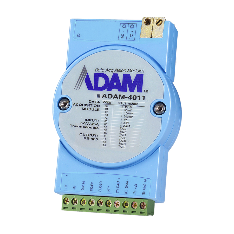
Page 39: Adam-4011D Thermocouple Input Module
3.2.1 ADAM-4011D Thermocouple Input Module Figure 3.1 ADAM-4011 Thermocouple Input Module Accepts: — J, K, T, E, R, S and B thermocouples — Millivolt inputs: ±15 mV, ±50 mV, ±100 mV and ±500 mV — Volt inputs: ±1 V and ±2.5 V — Current input: ±20 mA (Requires a 125…
-
Page 40: Adam-4011D Thermocouple Input Module
3.2.2 ADAM-4011D Thermocouple Input Module Figure 3.2 ADAM-4011D Thermocouple Input Module with LED Display Accepts: — J, K, T, E, R, S and B thermocouples — Millivolt inputs: ±15 mV, ±50 mV, ±100 mV and ±500 mV — Volt inputs: ±1 V and ±2.5 V — Current input: ±20 mA (Requires a 125 resistor) Two digital output channels and one digital input channel are provided.
-
Page 41: Application Wiring
3.2.3 Application Wiring Figure 3.3 ADAM-4011/4011D Thermocouple Input Wiring Diagram Figure 3.4 ADAM-4011/4011D Millivolt and Volt Input Wiring Diagram Figure 3.5 ADAM-4011/4011D Process Current Input Wiring Diagram ADAM-4000 Series User Manual…
-
Page 42: Figure 3.6 Adam-4011/4011D Digital Output Wiring Diagram Used With Ssr (Hi-Lo Alarm)
Figure 3.6 ADAM-4011/4011D Digital Output Wiring Diagram Used with SSR (HI- LO alarm) Figure 3.7 ADAM-4011/4011D Digital Input Wiring Diagram Used with TTL Figure 3.8 ADAM-4011/4011D Digital Input Wiring Diagram Used with Dry contact ADAM-4000 Series User Manual…
-
Page 43: Adam-4012 Analog Input Module
ADAM-4012 Analog Input Module The ADAM-4012 Analog Input Modules use a microprocessor controlled integrating A/D converter to convert sensor voltage or current signals into digital data. The digital data are then translated into either two’s complement hexadecimal format or percent- age of full-scale range (FSR) according to the module’s configuration.
-
Page 44: Adam-4012 Analog Input Module
3.3.1 ADAM-4012 Analog Input Module Figure 3.9 ADAM-4012 Analog Input Module Accepts: — Millivolt inputs ± 150 mV and ±500 mV — Volt inputs: ±1 V, ±5 V and ±10 V — Current input: ±20 mA (requires a 125 resistor) Two digital output channels and one digital input channel are provided.
-
Page 45: Application Wiring
3.3.2 Application Wiring Figure 3.10 ADAM-4012 Millivolt and Volt Input Wiring Diagram Figure 3.11 ADAM-4012 Process Current Input Wiring Diagram Figure 3.12 ADAM-4012 Digital Output Wiring Diagram Used with SSR (HI-LO alarm) ADAM-4000 Series User Manual…
-
Page 46: Ttl
Figure 3.13 ADAM-4012 Digital Input Wiring Diagram Used with TTL Figure 3.14 ADAM-4012 Digital Input Wiring Diagram Used with Dry contact ADAM-4000 Series User Manual…
-
Page 47: Adam-4013 Rtd Module
ADAM-4013 RTD Module The ADAM-4013 RTD Input Module supports one Pt or Ni RTD input channel for tem- perature measurement. This module can accept RTD sensors with two, three, or four wires. The module offers signal conditioning, A/D conversion, ranging, and RS-485 digital communication functions.
-
Page 48: Application Wiring
3.4.1 Application Wiring Figure 3.16 ADAM-4013 RTD Inputs Wiring Diagram ADAM-4000 Series User Manual…
-
Page 49: Adam-4015 6-Channel Rtd Input Module
ADAM-4015 6-channel RTD Input Module A RTD module is popularly used for temperature measurement. Unlike the traditional design, the ADAM-4015 RTD Input Module provides six RTD input channels for dif- ferent types of RTD signal like as Pt, Ni, Balco. It is an effective solution in industrial &…
-
Page 50: Application Wiring
3.5.1 Application Wiring Figure 3.18 ADAM-4015 RTD Input Module Wiring Diagram ADAM-4000 Series User Manual…
-
Page 51: Technical Specification Of Adam-4015
3.5.2 Technical specification of ADAM-4015 Table 3.1: Technical Specification of ADAM-4015 Channel Number 6 differential Support Protocol ADAM ASCII and MODBUS/RTU Input Type Pt100, Pt1000, BALCO500, Ni Input Connections 2 or 3 wires Wire Burnout Detection Yes Input Type and Temper- Pt100: -50 to 150°…
-
Page 52: Adam-4015T 6-Channel Thermistor Input Module
ADAM-4015T 6-channel Thermistor Input Module A Thermistor Module is popularly used for temperature measurement. Unlike the tra- ditional design, the ADAM-4015T provides six thermistor input channels for thermis- tor signal. It is an effective solution in industrial & building automation. Normally, broken external wires will lead to an inaccurate current value.
-
Page 53: Technical Specification Of Adam-4015T
3.6.2 Technical Specification of ADAM-4015T Table 3.2: Technical Specification of ADAM-4015T Channel Number 6 differential Support Protocol ADAM ASCII and MODBUS/RTU Input Type Thermistor Input Connections 2 or 3 wires Wire Burnout Detection Yes Input Type and Thermistor 3k 0~100? (9.796K ohm ~ 203.8 ohm) Temperature Range Thermistor 10k 0~100?(29.49K ohm ~ 816.8 ohm) Isolation Voltage…
-
Page 54: Adam-4016 Analog Input/Output Module
ADAM-4016 Analog Input/Output Module A strain gauge input module uses a microprocessor-controlled integrating A/D con- verter to convert sensor voltage or current signals into digital data for load cell and stress measurement. Digital data are then translated into either, two’s complement hexadecimal format or percentage of full-scale range (FSR) according to the mod- ule’s configuration.
-
Page 55: Figure 3.21Adam-4016 Analog Input/Output Module
Figure 3.21 ADAM-4016 Analog Input/Output Module Accepts: — Millivolt inputs: ±15 mV, ±50 mV, ±100 mV, ±500 mV — Current input: ±20 mA Excitation voltage output: 0 ~ 10 V Four digital output channels are provided. Depending on the module’s configuration setting, it can forward the data to the host computer in one of the following formats: — Engineering units (mV or mA) — Percent of full-scale range (FSR)
-
Page 56: Application Wiring
3.7.1 Application Wiring Figure 3.22 ADAM-4016 Strain Gauge Voltage Input Wiring Diagram Figure 3.23 ADAM-4016 Strain Gauge Current Input Wiring Diagram Figure 3.24 ADAM-4016 Digital Output Wiring Diagram Used with SSR ADAM-4000 Series User Manual…
-
Page 57: Adam-4017/4017+/4018/4018M/4018+ 8-Channel Analog Input Modules
ADAM-4017/4017+/4018/4018M/4018+ 8-channel Analog Input Modules 3.8.1 ADAM-4017/4018 8-channel Analog Input Module The ADAM-4017/4018 is a 16-bit, 8-channel analog input module that provides pro- grammable input ranges on all channels. This module is an extremely cost-effective solution for industrial measurement and monitoring applications. Its opto-isolated inputs provide 3000 VDC of isolation between the analog input and the module, and protect the module and peripherals from damage due to high input-line voltages.
-
Page 58: Adam-4018+ 8-Channel Thermocouple Input Module
3.8.4 ADAM-4018+ 8-channel Thermocouple Input Module ADAM-4018+ enables eight differential channels with multiple input types. This multi- channel/ multi-type structure allows synchronizing channels with different types of input. For example, channel 1 has K type of input meanwhile the others have R and S types.
-
Page 59: Adam-4017+ 8-Channel Differential Analog Input Module
3.8.6 ADAM-4017+ 8-channel Differential Analog Input Module Figure 3.26 ADAM-4017+ 8-ch. differential analog input module Jumper setting (ADAM-4017+) JP0~JP7 JP12 can Enable/Disable Watchdog Timer Function. The default setting is closed, i.e., Watchdog Timer Function Enabled. Please always keep JP12 closed and enable/disable the watchdog timer function in ADAM-utility. ADAM-4000 Series User Manual…
-
Page 60: Adam-4018 8-Channel Analog Input Module
3.8.6.1 Technical Specification of ADAM-4017+ Table 3.3: Technical Specification of ADAM-4017+ Channel Input Type mV, V, mA ±150 mV, ±500 mV, ±1 V, ±5 V, ±10 V, ±20 mA, 4 ~ 20 mA Input Range Current Input doesn’t need an external resistor 3000 V Isolation Voltage Fault and Over-voltage…
-
Page 61: Adam-4018M 8-Channel Analog Input Data Logger
— J, K, T, E, R, S and B thermocouples — Millivolt inputs: ±15 mV, ±50 mV, ±100 mV and ±500 mV — Volt inputs: ±1 V and ±2.5 V — Current input: ±20 mA (requires a 125 resistor) The module forwards the data to the host computer in engineering units (°C, mV, V or 3.8.8 ADAM-4018M 8-channel Analog Input Data logger Figure 3.28 ADAM-4018M 8-channel Analog Input Data Logger…
-
Page 62: Adam-4018+ 8-Channel Thermocouple Input Module
3.8.9 ADAM-4018+ 8-channel Thermocouple Input Module Figure 3.29 ADAM-4018+ 8-ch. thermocouple input module ADAM-4000 Series User Manual…
-
Page 63: Application Wiring
3.8.9.1 Technical specification of ADAM-4018+ Table 3.4: Technical specification of ADAM-4018+ Channel Input Type T Thermocouple Input range and ±20 mA, 4~20 mA T/C type J 0 ~ 760° C K 0 ~ 1370° C T -100 ~ 400° C E 0 ~ 1000°…
-
Page 64: Figure 3.32Adam-4017 Single-Ended Input Wiring Diagram (Ch6 And Ch7)
Figure 3.32 ADAM-4017 Single-ended Input Wiring Diagram (Ch6 and Ch7) Figure 3.33 ADAM-4017+ Voltage and Current Input Wiring Diagram ADAM-4000 Series User Manual…
-
Page 65: Adam-4019+ 8-Channel Universal Analog Input Module
Figure 3.34 ADAM-4018+ Thermocouple Input Wiring Diagram ADAM-4019+ 8-channel Universal Analog Input Module The ADAM-4019+ is universal analog input module to integrate with various AI mod- ules into one. It not only reduces the hardware cost, but also simplifies wiring com- plexity.
-
Page 66: Application Wiring
The jumper setting of ADAM-4019+ for input type selection: Note: With built in 120Ω resister inside. 3.9.1 Application Wiring Figure 3.36 ADAM-4019+ Universal Analog Input Wiring Diagram ADAM-4000 Series User Manual…
-
Page 67: Technical Specification Of Adam-4019
3.9.2 Technical Specification of ADAM-4019+ Table 3.5: Technical Specification of ADAM-4019+ Channel Resolution 16 bits Input Type V, mV, mA, T/C Input type and tempera- V: ±1 V , ±2.5 V, ±5 V , ±10 V ture range mV: ±100 mV , ±500 mV mA: ±20 mA (with 120 Ω…
-
Page 68: Figure 3.37Adam -4021 Analog Output Module
Figure 3.37 ADAM -4021 Analog Output Module Depending on its configuration settings the module accepts the following formats from the host computer: — Engineering units — Percent of full-scale range (FSR) — Two’s complement hexadecimal format, Output types: — Voltage: 0 ~ 10 V (Slew rate: 0.0625 to 64 V/sec) — Currents: 0 ~ 20 mA, or 4 ~ 20 mA.
-
Page 69: Application Wiring
3.10.1 Application Wiring Figure 3.38 ADAM-4021 Analog Output Wiring Diagram 3.11 ADAM-4024 4-channel Analog Output Module ADAM-4024 is a 4-channel analog output module with mixed type I/O. Under some circumstances, it is, however, a demand for multiple analog outputs to fulfill particular applications without many duplicate modules.
-
Page 70: Technical Specification Of Adam-4024
3.11.1 Technical Specification of ADAM-4024 Resolution: 12-bit Output Type: mA, V (Differential) Output Range: 0~20 mA, 4~20 mA, and ±10V Isolation Voltage: 3000 V Output Impedance: 0.5 Ω Accuracy: – ±0.1% of FSR for current output –…
-
Page 71: Adam-4050 Digital I/O Module
Figure 3.40 ADAM-4024 Pin Define and Wiring Diagram 3.12 ADAM-4050 Digital I/O Module The ADAM-4050 features seven digital input and eight digital output channels. The outputs are open-collector transistor switches that you can control from the host com- puter. You can also use the switches to control solid-state relays, which can be applied to equipments such as heaters and pumps.
-
Page 72: Figure 3.41Adam-4050 Digital I/O Module
Figure 3.41 ADAM-4050 Digital I/O Module Channels: — 7 input channels — 8 output channels Digital Input: Wet contact — Logic level 0: +1 V max. — Logic level 1: +3.5 ~ 30 V Dry contact — Logic level 1:Open — Logic level 0: Close to ground Digital Output: — Open collector to 30 V, 30 mA max.
-
Page 73: Application Wiring
3.12.1 Application Wiring Figure 3.42 ADAM-4050 Wet Contact Wiring Diagram Figure 3.43 ADAM-4050 Dry Contact Wiring Diagram ADAM-4000 Series User Manual…
-
Page 74: Figure 3.44Adam-4050 Digital Output Wiring Used With Inductive Load
Figure 3.44 ADAM-4050 Digital Output Wiring Used with inductive load Figure 3.45 ADAM-4050 Digital output wiring ADAM-4000 Series User Manual…
-
Page 75: Adam-4051 16-Channel Isolated Digital Input Module
3.13 ADAM-4051 16-channel Isolated Digital Input Module The ADAM-4051 is a 16 channel Digital Input Module. It is built with 2500VDC optical isolation, and it is suitable for critical applications. The main difference from other modules is that ADAM-4051 accepts 10 ~ 50V input voltage to fit various digital sig- nals like 12 V, 24 V, and 48 V.
-
Page 76: 61 3.13.1 Application Wiring
3.13.1 Application Wiring Figure 3.47 ADAM-4051 Dry Contact Wiring Diagram Figure 3.48 ADAM-4051 Wet Contact Wiring Diagram ADAM-4000 Series User Manual…
-
Page 77: Adam-4052 Isolated Digital Input Module
3.14 ADAM-4052 Isolated Digital Input Module The ADAM-4052 provides eight digital input channels. Among these eight channels, six of them are fully independent isolated channels and the other two are isolated channels with a common ground. They all have 5000 V isolation to prevent power surges from the input lines Figure 3.49 ADAM-4052 Isolated Digital Input Module…
-
Page 78: Application Wiring
3.14.1 Application Wiring Figure 3.50 ADAM-4052 Isolation Digital Input Wiring Ground 3.15 ADAM-4053 16-channel Digital Input Module The ADAM-4053 provides 16 digital input channels for dry contact or wet contact sig- nals. For dry contact, the effective distance from DI to contact point is up to 500 m. Figure 3.51 ADAM-4053 16-channel Digital Input Module ADAM-4000 Series User Manual…
-
Page 79
Channels: 16 Digital Input -Dry contact Logic level 0: Close to GND Logic level 1: OPEN -Wet contact Logic level 0: +2 V max. Logic level 1: +4 V to +30 V Note! There is one pin showing “INIT*/DI15” on the connector of the ADAM- 4053 module. -
Page 80: Application Wiring
3.15.1 Application Wiring Figure 3.52 ADAM-4053 Wet Contact Input Wiring Diagram Figure 3.53 ADAM-4053 Contact Closure Input Wiring Diagram ADAM-4000 Series User Manual…
-
Page 81: Adam-4055 16-Channel Isolated Digital I/O Module
3.16 ADAM-4055 16-channel Isolated Digital I/O Module The ADAM-4055 offers 8 channel isolated digital input and 8 channel isolated digital output for critical applications. The inputs accept 10~50 V voltage, and the outputs can supply 5~40 VDC at the open collector. The ADAM-4055 is user friendly with built LED indicator for status reading.
-
Page 82: Application Wiring
3.16.1 Application Wiring: Figure 3.55 ADAM-4055 Digital Output Wiring Diagram Figure 3.56 ADAM-4055 Digital Input Dry Contact Wiring Diagram ADAM-4000 Series User Manual…
-
Page 83: Figure 3.57Adam-4055 Digital Input Dry Contact Diagram (Inter Nal)
Figure 3.57 ADAM-4055 Digital Input Dry Contact Diagram (Internal) Figure 3.58 ADAM-4055 Digital Input Wet Contact Wiring Diagram ADAM-4000 Series User Manual…
-
Page 84: Figure 3.59Adam-4055 Digital Input Wet Contact Diagram (Inter Nal)
Figure 3.59 ADAM-4055 Digital Input Wet Contact Diagram (Internal) Figure 3.60 ADAM-4055 Default Jumper Setting for the Digital Input Wiring (Supports dry and wet contact digital inputs at the same time) ADAM-4000 Series User Manual…
-
Page 85: Figure 3.61Adam-4055 Default Jumper Setting For The Digital Input Wiring
Figure 3.61 ADAM-4055 Default Jumper Setting for the Digital Input Wiring ADAM-4000 Series User Manual…
-
Page 86: Adam-4056S 12-Channel Sink Type Isolated Digital Output Module
3.17 ADAM-4056S 12-channel Sink Type Isolated Digital Output Module ADAM-4056S is a 12-channel sink type isolated digital output module. The isolated channels are designed for digital output for critical applications. Open collector out- puts can provide from +5 to +40 VDC, and both ADAM ASCII and Modbus/RTU pro- tocols are supported.
-
Page 87: Application Wiring
3.17.2 Application Wiring Figure 3.63 ADAM-4056S Digital Output Wiring Diagram 3.18 ADAM-4056SO 12-channel Source Type Isolated Digital Output Module ADAM-4056SO is a 12-channel source type isolated digital output module. The 12 isolated digital output channels are designed for critical applications. The digital out- put signals are sent in the range of 10 ~ 35 VDC with maximum 1A per channel, and both ADAM ASCII and Modbus/RTU protocols are supported.
-
Page 88: Technical Specification Of Adam-4056So
Figure 3.64 ADAM-4056SO 12-channel Source Type Isolated Digital Output Module 3.18.1 Technical Specification of ADAM-4056SO – Number of Output Channel: 12 – Digital Output: VCC: +10 ~ 35VDC, 1A per Channel ( Source) – LED Indicator: On: Active, Off: Non-active –…
-
Page 89: Application Wiring
3.18.2 Application Wiring Figure 3.65 ADAM-4056SO Digital Output Wiring Diagram 3.19 ADAM-4060/4068 Relay Output Module The ADAM Relay Output Module is a low-cost alternative to SSR modules. The ADAM-4060 Relay Output Module provides four relay channels; two of them are Form A, and two are Form C.
-
Page 90: Adam-4060 4-Channel Relay Output Module
3.19.1 ADAM-4060 4-channel Relay Output Module Figure 3.66 ADAM-4060 4-channel Relay Output Module Contact rating for Form A and Form C: (Resistive) 0.6 A @ 125 V 0.3 A @ 250 V 2 A @ 30 V 0.6 A @ 110 V ADAM-4000 Series User Manual…
-
Page 91: Adam-4068 8-Channel Relay Output Module
3.19.2 ADAM-4068 8-channel Relay Output Module Figure 3.67 ADAM-4068 8-channel Relay Output Module Contact Rating for Form A and Form C: (Resistive) 0.5 A @120 V 0.25 A @240 V 1 A @ 30 V 0.3 A @ 110 V Note! This electric current is under the load of resistance.
-
Page 92: Application Wiring
3.19.3 Application Wiring The following diagrams are examples of how to connect Form A and Form C relay output applications to your ADAM modules. Figure 3.68 ADAM-4060 Form A Relay Output Wiring Diagram Figure 3.69 ADAM-4060 Form C Relay Output Wiring Diagram Figure 3.70 ADAM-4068 Form C Relay Output Wiring Diagram ADAM-4000 Series User Manual…
-
Page 93: Adam-4069 8-Channel Relay Output Module
Figure 3.71 ADAM-4068 Form A relay output Wiring Diagram 3.20 ADAM-4069 8-channel Relay Output Module The ADAM-4069 Relay Output Module provides eight channels; four are Form A and the rest are Form C. This module is excellent for ON/OFF control or low-power switching applications.
-
Page 94: Specification
3.20.1 Specification Number of Relay Output Channel: 8 Digital Output: (Source) – 4 Form A, 4 Form C – AC 5A@250V – DC 5A@30V – ON/OFF: 5ms/ 5.6ms Power Consumption: 2.6 W Supports Modbus/RTU protocol I/O Connector Type: 13-pin plug-terminal * 2 …
-
Page 95: Adam-4080/4080D Counter/Frequency Input Modules
3.21 ADAM-4080/4080D Counter/Frequency Input Modules ADAM-4080/4080D Counter/frequency input module has two 32-bit counter input channels (counter 0 and counter 1) with built-in programmable timer for frequency measurement. These cost-effective modules let you monitor counter/frequency data as measurements are taken. Front Panel LED Indicator (ADAM-4080D only) The 5-digit LED display of the ADAM-4080D lets you monitor its counter data right at the source.
-
Page 96: Adam-4080 Counter/Frequency Input Modules
The alarm functions can be enabled or disabled remotely. When the alarm functions are enabled, digital output channels are used to indicate the alarm states. For ADAM- 4080, digital output channel 0 equals to the alarm state of counter 0, and digital out- put channel 1 equals to the alarm state of counter 1.
-
Page 97: Adam-4080D Counter/Frequency Input Modules With Led Display
Channels: 2 independent 32-bit counters (counter 0 and counter 1) Input frequency: 50 kHz max. Input mode: Isolated or non-isolated Protocol: ASCII, Modbus/RTU (E version) Isolation input level: — Logic level 0: +1 V max — Logic level 1: +3.5 V to +30 V — Gate Logic level 0: the same as the setting of Logic level 0 — Gate Logic level 1: the same as the setting of Logic level 1 — Input Impedance: 1.2 kΩ, 1kΩ…
-
Page 98: Application Wiring
Channels: 2 independent 32-bit counters (counter 0 and counter 1) Input frequency: 50 kHz max. Input mode: Isolated or non-isolated Isolation input level: — Logic level 0: +1 V max — Logic level 1: +3.5 V to +30 V — Input Impedance: 1.2 kΩ Non-isolation input level (programmable threshold): — Logic level 0: 0 to +5V (default = 0.8 V) — Logic level 1: 0 to +5V (default = 2.4 V)
-
Page 99: Figure 3.79Adam-4080 Digital Output Wiring
Figure 3.79 ADAM-4080 Digital output wiring ADAM-4000 Series User Manual…
-
Page 100
ADAM-4000 Series User Manual… -
Page 101: Command Set
Chapter Command Set…
-
Page 102: Introduction
Introduction In order to avoid communication conflicts among devices trying to send data simulta- neously, all the traffics are coordinated by the host computer. This action is initiated by the host computer using a command/response protocol. When the modules are not transmitting, they are in listening mode. The host issues a command to a module with a specified address and waits for the module’s response.
-
Page 103: I/O Module Commands Search Table
I/O Module Commands Search Table Table 4.1: ADAM-4011 Command Table Command Syntax Command Name Command Description Page No. Sets the address, input range, baud rate, data format, checksum status, %AANNTTCCFF Configuration and/or integration time for a specified analog input module Returns the configuration parameters $AA2 Configuration Status…
-
Page 104: Table 4.2: Adam-4011D Command Table
Table 4.2: ADAM-4011D Command Table Command Syntax Command Name Command Description Page No. Sets the address, input range, baud rate, data format, checksum status, %AANNTTCCFF Configuration and/or integration time for a specified analog input module Returns the configuration parameters $AA2 Configuration Status 5-10 for the specified analog input module…
-
Page 105: Table 4.3: Adam-4012 Command Table
Table 4.3: ADAM-4012 Command Table Command Syntax Command Name Command Description Page No. Sets the address, input range, baud rate, data format, checksum status, %AANNTTCCFF Configuration and/or integration time for a specified analog input module Returns the input value from a speci- Analog Data In fied analog input module in the cur- 5-14…
-
Page 106: Table 4.4: Adam-4013 Command Table
Table 4.4: ADAM-4013 Command Table Command Syntax Command Name Command Description Page No. Sets the address, input range, baud rate, data format, checksum status, %AANNTTCCFF Configuration and/or integration time for a specified analog input module Returns the input value from a speci- Analog Data In fied analog input module in the cur- 5-14…
-
Page 107: Table 4.6: Adam-4016 Command Table
Table 4.5: ADAM-4015/ADAM-4015T Command Table Get the enable/disable status of all $AA6 Read Channel Status 5-18 channels in an analog module Calibrates an analog input module to $AA0 Span Calibration 5-19 correct for gain errors Calibrates an analog input module to $AA1 Offset Calibration 5-20…
-
Page 108
Table 4.6: ADAM-4016 Command Table Return the input value from the speci- Read Analog Input fied analog input module in the cur- 5-14 rently configured data format Calibrates an analog input module to $AA0 Span Calibration 5-19 correct for gain errors Calibrates an analog input module to $AA1 Offset Calibration… -
Page 109: Table 4.7: Adam-4017 Command Table
Table 4.7: ADAM-4017 Command Table Command Syntax Command Name Command Description Page No. Sets the address, input range, baud rate, data format, checksum status, %AANNTTCCFF Configuration and/or integration time for a specified analog input module Return the configuration parameters $AA2 Configuration Status 5-10 for the specified analog input module…
-
Page 110: Source For Each Input Type
Table 4.8: ADAM-4017+ Command Table Get the enable/disable status of all $AA6 Read Channel Status 5-18 channels in an analog module Single Channel Calibrates a specified channel to cor- $AA0Ci 5-27 Span Calibration rect for gain errors Single Channel Calibrates a specified channel to cor- $AA1Ci 5-28 Offset Calibration…
-
Page 111: Table 4.10: Adam-4018 Command Table
Table 4.10: ADAM-4018 Command Table Command Syntax Command Name Command Description Page No. Sets the address, input range, baud rate, data format, checksum status, %AANNTTCCFF Configuration and/or integration time for a specified analog input module Return the configuration parameters $AA2 Configuration Status 5-10 for the specified analog input module…
-
Page 112: Table 4.11: Adam-4018+ Command Table
Table 4.11: ADAM-4018+ Command Table Command Syntax Command Name Command Description Page No. Sets the address, input range, baud rate, data format, checksum status, %AANNTTCCFF Configuration and/or integration time for a specified analog input module Return the configuration parameters $AA2 Configuration Status 5-10 for the specified analog input module…
-
Page 113: Source For Each Input Type
Table 4.12: ADAM-4018+ Input range and external calibrating input source for each input type Range Displayed Input Range Max. Signal Min Signal bcode(Hex) Resolution +/-20 mA +20.000 -20.000 4~20 mA +20.000 +4.000 Type J Thermocouple Type K Thermocouple Type T Thermocouple Type E Thermocouple…
-
Page 114
Table 4.13: ADAM-4018M Command Table Get the channel operating status When bit value is 0, it means this $AAB Get Operating Status channel is in normal operating, when 5-24 bit value is 1, it means this channel is opening wire Returns the value of the CJC sensor $AA3 CJC Status… -
Page 115: Table 4.14: Adam-4019+ Command Table
Table 4.14: ADAM-4019+ Command Table Command Syntax Command Name Command Description Page No. Sets the address, input range, baud rate, data format, checksum status, %AANNTTCCFF Configuration and/or integration time for a specified analog input module Return the configuration parameters $AA2 Configuration Status 5-10 for the specified analog input module…
-
Page 116: Table 4.15: Adam-4021 Command Table
Table 4.15: ADAM-4021 Command Table Command Syntax Command Name Command Description Page No. Set the address, output range, baud %AANNTTCCFF Configuration rate, data format, slew rate and/or checksum status Directs output data to a specified #AA(data) Analog Data Out module Start-up output cur- Stores a default output value in a $AA4…
-
Page 117: Table 4.16: Adam-4024 Command Table
Table 4.16: ADAM-4024 Command Table Command Syntax Command Name Command Description Page No. Set the address, output range, baud %AANNTTCCFF Configuration rate, data format, slew rate and/or 6-19 checksum status Directs output data to a specified #AACn(data) Analog Data Out 6-20 module #AASCn(data)
-
Page 118: Table 4.17: Adam-4050 Command Table
Table 4.16: ADAM-4024 Command Table Clear 4mA Calibra- Clear CHn 4mA Calibration $AAPCn 6-21 tion Parameter Parameter/EEPROM Clear 20mA Calibra- Clear CHn 20mA Calibration $AAQCn 6-21 tion Parameter Parameter/EEPROM Set communication W DT cycle time Watchdog Timer from 0000 ~ 9999 (unit: 0.1 second. if $AAX0nnnn 6-21 Setting…
-
Page 119: Table 4.18: Adam-4051 Command Table
Table 4.18: ADAM-4051 Command Table Command Syntax Command Name Command Description Page No. Sets the address, baud rate, and/or %AANNTTCCFF Configuration checksum status to a digital I/O module Orders all digital I/O modules to Synchronized sample their input values and store 7-11 Sampling them in special registers…
-
Page 120: Table 4.19: Adam-4052 Command Table
Table 4.19: ADAM-4052 Command Table Command Syntax Command Name Command Description Page No. Sets address, baud rate, and/or %AANNTTCCFF Configuration checksum status, to a digital I/O module Returns the values of the digital I/O $AA6 Digital Data In channels of the addressed module Orders all digital I/O modules to Synchronized sample their input values and store…
-
Page 121: Table 4.21: Adam-4055 Command Table
Table 4.21: ADAM-4055 Command Table Command Syntax Command Name Command Description Page No. Sets the address, baud rate, and/or %AANNTTCCFF Configuration checksum status to a digital I/O module Writes specified values to either a #AABB(data) Digital Data Out single channel or all channels simul- taneously Orders all digital I/O modules to Synchronized…
-
Page 122: Table 4.22: Adam-4056S Command Table
Table 4.22: ADAM-4056S Command Table Command Syntax Command Name Command Description Page No. Sets the address, baud rate, and/or %AANNTTCCFF Configuration checksum status to a digital I/O module Writes specified values to either a #AABB(data) Digital Data Out single channel or all channels simul- taneously Returns the configuration parame- $AA2…
-
Page 123: Table 4.23: Adam-4056So Command Table
Table 4.23: ADAM-4056SO Command Table Command Syntax Command Name Command Description Page No. Sets the address, baud rate, and/or %AANNTTCCFF Configuration checksum status to a digital I/O module Writes specified values to either a #AABB(data) Digital Data Out single channel or all channels simul- taneously Returns the configuration parame- $AA2…
-
Page 124: Table 4.24: Adam-4060/4068 Command Table
Table 4.24: ADAM-4060/4068 Command Table Command Syntax Command Name Command Description Page No. Sets address, baud rate, and/or %AANNTTCCFF Configuration checksum status, to a digital I/O module Returns the values of the digital I/O $AA6 Digital Data In channels of the addressed module Writes specified values to either a #AABB(data) Digital Data Out…
-
Page 125: Table 4.25: Adam-4069 Command Table
Table 4.25: ADAM-4069 Command Table Command Syntax Command Name Command Description Page No. Sets address, baud rate, and/or %AANNTTCCFF Configuration checksum status, to a digital I/O mod- Returns the values of the digital I/O $AA6 Digital Data In channels of the addressed module Writes specified values to either a #AABB(data) Digital Data Out…
-
Page 126: Table 4.26: Adam-4080 Command Table
Table 4.26: ADAM-4080 Command Table Command Syntax Command Name Command Description Page No. Sets the address, input mode, baud rate, checksum status and/or fre- %AANNTTCCFF Configuration 7-28 quency gate time for a specified counter/ frequency module Returns configuration parameters $AA2 Configuration Status from the specified counter/frequency 7-30…
-
Page 127
Table 4.26: ADAM-4080 Command Table The addressed counter frequency $AA4 Read Filter Status module returns the status of its digital 7-50 filter Set Minimum Input Sets the minimum input signal width $AA0H(data) Signal Width at High at high level for a specified counter/ 7-51 Level frequency module… -
Page 128: Table 4.27: Adam-4080D Command Table
Table 4.27: ADAM-4080D Command Table Command Syntax Command Name Command Description Page No. Sets the address, input mode, baud rate, checksum status and/or fre- %AANNTTCCFF Configuration 7-28 quency gate time for a specified counter/ frequency module Returns configuration parameters $AA2 Configuration Status from the specified counter/frequency 7-30…
-
Page 129
Table 4.27: ADAM-4080D Command Table The command clears the counter 0 $AA6N Clear Counter or counter 1 of the specified counter 7-46 module The addressed module returns the $AA7N Read Overflow Flag status of the overflow flag of counter 7-47 0 or counter 1 Enables or disables the digital… -
Page 130
Table 4.27: ADAM-4080D Command Table Set Digital Output Set the values of the module’s two @AADO(data) 7-67 Values digital outputs(ON or OFF) Ask the module to return the status Read Digital Output @AADI state of its two digital outputs and the 7-68 and Alarm Status status of its alarm. -
Page 131: Chapter 5 Analog Input Module Commands
Chapter Analog Input Module Commands…
-
Page 132: Analog Input Common Command Set
Analog Input Common Command Set Command Syntax Description I/O Module %AANNTTCCFF Sets the address, input range, 4011, 4011D, 4012, 4013, 4015, baud rate, data format, checksum 4015T, 4016, 4017, 4017+, 4018, status, and/or integration time for 4018+, 4018M, 4019+ a specified analog input module $AA2 Returns the configuration parame- 4011, 4011D, 4012, 4013, 4015,…
-
Page 133: Aannttccff
$AA7CiRrr Configure the input type and 4015, 4015T, 4017+, 4018+, 4019+ range of the specified channel in an analog input module $AA8Ci Get the input type and range of the 4015, 4015T, 4017+, 4018+, 4019+ specified channel in an analog input module $AAXnnnn Communication Watchdog Timer…
-
Page 134: Figure 5.1 Data Format For Ff (8-Bit Parameter)
Checksum status not used Data Format 0: Disabled 00: Engineering units 1: Enabled 01: % of FSR 10: two’s complement of hexadecimal Integration time 11: Ohms (for 4013 and 4015) 0: 50 ms (Operation under 60 Hz power) 1: 60 ms (Operation under 50 Hz power) Figure 5.1 Data format for FF (8-bit parameter) Response !AA(cr) if the command is valid.
-
Page 135: Table 5.1: Input Range Codes (Type Codes)
Table 5.1: Input Range Codes (Type Codes) Input Range Code (Hex) Input Range for 4011, 4011D, 4018, 4018+ (Thermocouple and ± 20 mA only), 4018M ± 15 mV ± 50 mV ± 100 mV ± 500 mV ± 1 V ±…
-
Page 136: Table 5.2: Adam-4015/4015T Command Codes Against Input Ranges Table
Table 5.2: ADAM-4015/4015T command codes against Input ranges table Command Code (Hex) Input Type Input Range Platinum 100 (IEC) -50 ~ 150 °C Platinum 100 (IEC) 0 ~ 100 °C Platinum 100 (IEC) 0 ~ 200 °C Platinum 100 (IEC) 0 ~ 400 °C Platinum 100 (IEC) -200 ~ 200 °C…
-
Page 137: Aa2
Table 5.3: Baud Rate Codes Baud Rate Code (Hex) Baud Rate 1200 bps 2400 bps 4800 bps 9600 bps 19.2 kbps 38.4 kbps 4011, 4011D, 4012, 4013, 4015, 4015T, 4016, 4017, 4017+, 4018, 4018+, 4018M, 4019+ 5.1.2 $AA2 Name Configuration Status command Description The command requests the return of the configuration data from the analog input module at address AA.
-
Page 138: Aaf
Example command: $452(cr) response: !45050600(cr) The command asks the analog input module at address 45h to send its configuration data. The analog input module at address 45h responds with an input range of 2.5 volts, a baud rate of 9600 bps, an integration time of 50 ms (60 Hz), engineering units are the currently configured data format, and no checksum function or checksum generation.
-
Page 139: Aam
4011, 4011D, 4012, 4013, 4015, 4015T, 4016, 4017, 4017+, 4018, 4018+, 4018M, 4019+ 5.1.4 $AAM Name Read Module Name command Description The command requests the analog input module at address AA to return its name. Syntax $AAM (cr) $ is a delimiter character. AA (range 00-FF) represents the 2-character hexadecimal address of the analog input module that you want to interrogate.
-
Page 140
4011, 4011D, 4012, 4013, 4015, 4015T, 4016, 4017, 4017+, 4018, 4018+, 4018M, 4019+ 5.1.5 Name Analog Data In command Description The command will return the input value from a specified (AA) module in the currently configured data format. Syntax #AA(cr) # is a delimiter character. -
Page 141
Caution! When modules measure Thermocouple or RTD input values that are outside their configured range they will send data that implies input out of bounds. The next table shows the values that the modules will return, depending on the configured data format and if the input value falls under or exceeds the configured range. -
Page 142: Aan
4015, 4015T, 4017, 4017+, 4018, 4018+, 4018M, 4019+ 5.1.6 #AAN Name Read Analog Input from Channel N command Description The command will return the input value from one of the eight channels of a specified (AA) module in the currently configured data format.
-
Page 143: Aa5Vv
4015, 4015T, 4017, 4017+, 4018, 4018+, 4018M, 4019+ 5.1.7 $AA5VV Name Enable/disable Channels for Multiplexing command Description Enables/disables multiplexing simultaneously for separate channels of a specified input module. Syntax $AA5VV(cr) $ is a delimiter character. AA (range 00-FF) represents the 2-character hexadecimal address of analog input module.
-
Page 144: Aa6
4015, 4015T, 4017, 4017+, 4018, 4018+, 4018M, 4019+ 5.1.8 $AA6 Name Read Channel Status command Description Asks a specified input module to return the status of all channels. Syntax $AA6(cr) AA (range 00-FF) represents the 2-character hexadecimal address of analog input module of which the channel status you want to send.
-
Page 145: Aa0
4011, 4011D, 4012, 4013, 4016, 4017, 4018, 4018M 5.1.9 $AA0 Name Span Calibration command Description Calibrates an analog input module to correct for gain errors. Syntax $AA0(cr) $ is a delimiter character. AA (range 00-FF) represents the 2-character hexadecimal address of the analog input module which is to be calibrated. 0 is the Span Calibration command.
-
Page 146: Aa1
4011, 4011D, 4012, 4013, 4016, 4017, 4018, 4018M 5.1.10 $AA1 Name Offset Calibration command Description Calibrates an analog input module to correct for offset errors. Syntax $AA1(cr) $ is a delimiter character. AA (range 00-FF) represents the 2-character hexadecimal address of the analog input module you want to calibrate. 1 is the Offset Calibration command.
-
Page 147: Aa4
4011, 4011D, 4012, 4013, 4015, 4015T, 4016 5.1.11 Name Synchronized sampling comand Description Orders all analog input modules to sample their input values and store the values in special registers. Syntax # is a delimiter character. ** is the Synchronized Sampling command. The terminating character, in the form of a carriage return (0Dh), is not required.
-
Page 148
(data) a value stored in a special register of the interrogated module in the configured data format. It has been sampled by the module after a Synchronized Sampling command. (For possible data formats, see Appendix B, Data Formats and I/O Ranges) (cr) represents terminating character, carriage return (0Dh). -
Page 149: Aab
4011D, 4015, 4015T, 4018+, 4019+ 5.1.13 $AAB Name Channel Diagnose command Description Diagnose channel status in over range, under range, and wire opening. Syntax $AAB(cr) $ is a delimiter character. AA (range 00-FF) represents the 2-character hexadecimal address of the analog input module to be detected. B is the Channel Diagnose command.
-
Page 150: Aa3
4011, 4011D, 4018, 4018+, 4018M, 4019+ 5.1.14 $AA3 Name CJC Status command Description Instructs the addressed analog input module to read its CJC (Cold Junction Compensation) sensors and return the acquired data. Syntax $AA3(cr) $ is a delimiter character. AA (range 00-FF) represents the 2-character hexadecimal address of the analog input module which contains the CJC Status you wish to retrieve.
-
Page 151: Aa9Snnnn
4011, 4011D, 4018, 4018+, 4018M, 4019+ 5.1.15 $AA9SNNNN Name CJC Offset Calibration command Description Calibrates an analog input module to adjust for offset errors of its CJC (Cold Junction Compensation) sensors. Syntax $AA9SNNNN(number of counts)(cr) $ is a delimiter character. AA (range 00-FF) represents the 2-character hexadecimal address of the analog input module which contains the CJC status you wish to retrieve.
-
Page 152: Aa0Ci
4015, 4015T, 4017+, 4018+, 4019+ 5.1.16 $AA0Ci Name Single Channel Span Calibration command Description The command calibrates a specified channel to correct for gain errors. Syntax $AA0Ci(cr) $ is a delimiter character. AA (range 00-FF) represents the 2-character hexadecimal address of the analog input module which is to be calibrated. 0 is the Single Channel Span Calibration command.
-
Page 153: Aa1Ci
4015, 4015T, 4017+, 4018+, 4019+ 5.1.17 $AA1Ci Name Single Channel Offset Calibration command Description The command calibrates a specified channel to correct for offset errors. Syntax $AA1Ci(cr) $ is a delimiter character. AA (range 00-FF) represents the 2-character hexadecimal address of the analog input module which is to be calibrated. 1 is the Single Channel Offset Calibration command.
-
Page 154: Aa7Cirrr
4015, 4015T, 4017+, 4018+, 4019+ 5.1.18 $AA7CiRrr Name Single Channel Range Configuration command Description This command configures the input type and range of the specified channel in an analog input module. Syntax $AA7CiRrr(cr) $ is a delimiter character. AA (range 00-FF) represents the 2-character hexadecimal address of the analog input module which is to be configured.
-
Page 155: Aa8Ci
4015, 4015T, 4017+, 4018+, 4019+ 5.1.19 $AA8Ci Name Read Single Channel Range Configuration command Description This command read the input type and range configuration of the specified channel in an analog input module. Syntax $AA8Ci(cr) $ is a delimiter character. AA (range 00-FF) represents the 2-character hexadecimal address of the analog input module which is to be read.
-
Page 156: Aaxnnnn
4015, 4015T, 4017+, 4018+, 4019+ 5.1.20 $AAXnnnn Name Watchdog Timer Setting command Description This command set the communication watchdog timer (WDT) cycle time. Syntax $AAXnnnn(cr) $ is a delimiter character. AA (range 00-FF) represents the 2-character hexadecimal address of the analog input module which is to be read. X is the Watchdog Timer Setting command.
-
Page 157: Aay
4015, 4015T, 4017+, 4018+, 4019+ 5.1.21 $AAY Name Read Communication Watchdog Timer Cycle Setting command Description This command read the setting of communication watchdog timer (WDT) cycle time. Syntax $AAY(cr) $ is a delimiter character. AA (range 00-FF) represents the 2-character hexadecimal address of the analog input module which is to be read.
-
Page 158: Aas0
4015, 4015T 5.1.22 $AAS0 Name Internal Calibration command Description This command executes internal self-calibration for offset and gain errors. Syntax $AAS0(cr) $ is a delimiter character. AA (range 00-FF) represents the 2-character hexadecimal address of the analog input module which is to be calibrated. S0 is the Internal Calibration command.
-
Page 159: Analog Input Data Logger Command Set
Analog Input Data Logger Command Set Command Syntax Command Name Description I/O Module @AACCCSDMTT TT Set Memory Set the channel storage status, 4018M Configuration standalone mode, data logger mode, storage type and sampling interval for the specified analog input data logger. @AAD Read Memory Return the configuration parame-…
-
Page 160
Channel 7 Channel 0 Bit 7 Bit 6 Bit 5 Bit 4 Bit 3 Bit 2 Bit 1 Bit 0 S represents the standalone mode. In order for the ADAM-4018M to operate in the field, you must power on the memory module by setting this value to ‘1.’ Otherwise, the data will not be recorded. -
Page 161: Aad
4018M 5.2.2 @AAD Name Read Memory Configuration command Description The command requests the configuration data from the analog input data logger at address AA. Syntax @AAD (cr) @ is a delimiter character. AA (range 00-FF) represents the 2-character hexadecimal address of an analog input data logger. D is the Read Memory Configuration command.
-
Page 162: Aad
4018M 5.2.3 @AAD Name Read Memory Configuration command Description The command requests the configuration data from the analog input data logger at address AA. Syntax @AAD (cr) @ is a delimiter character. AA (range 00-FF) represents the 2-character hexadecimal address of an analog input data logger. D is the Read Memory Configuration command.
-
Page 163: Aaso
4018M 5.2.4 @AASO Name Set Memory Operation Mode command Description Sets the operation mode of the analog input data logger at address AA to Start or Stop. Syntax @AASO(cr) @ is a delimiter character. AA (range 00-FF) represents the 2-character hexadecimal address of an analog input data logger.
-
Page 164: Aat
4018M 5.2.5 @AAT Name Read Memory Operation Mode command Description Request the memory operation status of the analog input data logger at address AA. Syntax @AAT (cr) @ is a delimiter character. AA (range 00-FF) represents the 2-character hexadecimal address of an analog input data logger. T is the Read Memory Operation Mode command.
-
Page 165: Aal
4018M 5.2.6 @AAL Name Event Record Count command Description Request the number of event records stored in the analog input data logger at address AA. Syntax @AAL (cr) @ is a delimiter character. AA (range 00-FF) represents the 2-character hexadecimal address of an analog input data logger.
-
Page 166: Aan
4018M 5.2.7 @AAN Name Standard Record Count command Description Request the number of standard records stored in the analog input data logger at address AA. Syntax @AAN (cr) @ is a delimiter character AA (range 00-FF) represents the 2-character hexadecimal address of an analog input data logger.
-
Page 167: Aarnnnn
4018M 5.2.8 @AARNNNN Name Read Record Content command Description Request the content of record NNNN stored in the analog input data logger at address AA. Syntax @AARNNNN (cr) @ is a delimiter character. AA (range 00-FF) represents the 2-character hexadecimal address of an analog input data logger.
-
Page 168: Aaacsdhhhhteiiii
4018M 5.2.9 @AAACSDHHHHTEIIII Name Set Alarm Limit command Description Set high/low alarm limits for the channel C in the analog input data logger at address AA. Syntax @AAACSDHHHHTEIIII(cr) @ is a delimiter character AA (range 00-FF) represents the 2-character hexadecimal address of an analog input data logger.
-
Page 169: Aabc
4018M 5.2.10 @AABC Name Read Alarm Limit command Description Request the alarm limits for the specified channel in the analog input data logger at address AA. Syntax @AABC(cr) @ is a delimiter character. AA (range 00-FF) represents the 2-character hexadecimal address of an analog input data logger.
-
Page 170: Digital I/O, Alarm And Event Command Set
Digital I/O, Alarm and Event Command Set Command Syntax Command Name Description I/O Module @AADI Read Digital I/O and The addressed module returns 4011, 4011D, Alarm Status the state of its digital input and 4012, 4016 digital output channels and the status of its alarm @AADO(data) Set Digital Output…
-
Page 171: Aadi
4011, 4011D, 4012, 4016 5.3.1 @AADI Name Read Digital I/O and Alarm State Description The addressed analog input module is instructed to return the value of its digital input and output channels and the state of its alarm (Momentary or Latching). Syntax @AADI(cr) @ is a delimiter character.
-
Page 172
Status Code II is a hexadecimal number representing the Digital input port’s channel status (00h = D/I channel is Low, 01h = channel is High). (cr) represents terminating character, carriage return (0Dh). Example command: @15DI(cr) response: !510001(cr) The analog input module at address 15h is instructed to return digital I/O data and alarm status. -
Page 173: Aado
4011, 4011D, 4012, 4016 5.3.2 @AADO Name Set Digital Output command Description Sets the values of the module’s digital outputs (ON or OFF). Syntax @AADO(data)(cr) @ is a delimiter character. AA (range 00-FF) represents the 2-character hexadecimal address of an analog input module. DO is the Set Digital Output command.
-
Page 174: Aaeat
4011, 4011D, 4012, 4016 5.3.3 @AAEAT Name Enable Alarm command Description The addressed analog input module is instructed to enable its alarm in either Latching or Momentary mode. Syntax @AAEAT(cr) @ is a delimiter character. AA (range 00-FF) represents the 2-character hexadecimal address of an analog input module.
-
Page 175: Aahi
4011, 4011D, 4012, 4016 5.3.4 @AAHI Name Set High Alarm Limit command Description Downloads high alarm limit value into the addressed module. Syntax @AAHI(data)(cr) @ is a delimiter character. AA (range 00-FF) represents the 2-character hexadecimal address of an analog input module. HI is the Set High Limit command.
-
Page 176: Aalo
4011, 4011D, 4012, 4016 5.3.5 @AALO Name Set Low Alarm Limit command Description Downloads Low alarm limit value into the addressed module. Syntax @AALO(data)(cr) @ is a delimiter character. AA (range 00-FF) represents the 2-character hexadecimal address of an analog input module. LO is the Set Low Limit command.
-
Page 177: Aada
4011, 4011D, 4012, 4016 5.3.6 @AADA Name Disable Alarm command Description Disables all alarm functions of the addressed analog input module. Syntax @AADA(cr) @ is a delimiter character. AA (range 00-FF) represents the 2-character hexadecimal address of an analog input module. DA is the Disable Alarm command.
-
Page 178: Aaca
4011, 4011D, 4012, 4016 5.3.7 @AACA Name Clear Latch Alarm command Description Both alarm states (High and Low) of the addressed analog input module are set to OFF, no alarm. Syntax @AACA(cr) @ is a delimiter character. AA (range 00-FF) represents the 2-character hexadecimal address of an analog input module.
-
Page 179: Aarh
4011, 4011D, 4012, 4016 5.3.8 @AARH Name Read High Alarm Limit command Description The addressed module is asked to return its High alarm limit value. Syntax @AARH(cr) @ is a delimiter character. AA (range 00-FF) represents the 2-character hexadecimal address of an analog input module. RH is the Read High Alarm Limit command.
-
Page 180: Aarl
4011, 4011D, 4012, 4016 5.3.9 @AARL Name Read Low Alarm Limit command Description The addressed module is asked to return its Low alarm limit value. Syntax @AARL(cr) @ is a delimiter character. AA (range 00-FF) represents the 2-character hexadecimal address of an analog input module. RL is the Read Low Alarm Limit command.
-
Page 181: Aare
4011, 4011D, 4012 5.3.10 @AARE Name Read Event Counter command Description The addressed module is instructed to return its event counter value. Syntax @AARE(cr) @ is a delimiter character. AA (range 00-FF) represents the 2-character hexadecimal address of an analog input module. RE is the Reads Event Counter command.
-
Page 182: Aace
4011, 4011D, 4012 5.3.11 @AACE Name Clear Event Counter command Description The addressed module is instructed to reset its event counter to zero. Syntax @AACE(cr) @ is a delimiter character. AA (range 00-FF) represents the 2-character hexadecimal address of an analog input module. CE is the Clear Event Counter command.
-
Page 183: Aa6
4016 5.4.1 $AA6 Name Get Excitation Voltage Output Value command Description The addressed strain gauge input module is instructed to return the latest output value it received from Excitation Voltage Output command. If the module hasn’t received an Excitation Voltage Output command since startup, it will return its Start-up Output value.
-
Page 184: Aa7
4016 5.4.2 $AA7 Name Excitation Voltage Output command Description Send a value to the analog output channel of the addressed strain gauge input module. Upon receipt, the analog output channel will output this value. Syntax $AA7(data)(cr) $ is a delimiter character. AA (range 00-FF) represents the 2-character hexadecimal address of the strain gauge input module.
-
Page 185: Aas
4016 5.4.3 $AAS Name Start-up Voltage Output Configuration command Description Stores the present analog output value of the strain gauge input module with address AA in the module’s non-volatile register. The output value will take effect upon start-up or after a brownout. Syntax $AAS(cr) $ is a delimiter character.
-
Page 186: Aae
4016 5.4.4 $AAE Name Trim Calibration command Description Trims the output voltage of the strain gauge input module a specified number of units up or down. Syntax $AAE(number of counts)(cr) $ is a delimiter character. AA (range 00-FF) represents the 2-character hexadecimal address of the strain gauge input module to be calibrated.
-
Page 187: Aaa
4016 5.4.5 $AAA Name Zero Calibration command Description Stores the voltage output value of the addressed strain gauge input module as zero voltage reference. Syntax $AAA(cr) $ is a delimiter character. AA (range 00-FF) represents the 2-character hexadecimal address of the strain gauge input module whose output channel is to be calibrated.
-
Page 188: Aab
4016 5.4.6 $AAB Name Span Calibration command Description Stores the voltage output value of the addressed strain gauge input module as 10V reference. Syntax $AAB(cr) $ is a delimiter character. AA (range 00-FF) represents the 2-character hexadecimal address of the strain gauge input module whose output channel is to be calibrated.
-
Page 189: Analog Output Module Commands175
Chapter Analog Output Module Commands…
-
Page 190: Analog Output Module Command For Adam-4021
Analog Output Module Command for ADAM- 4021 Command Syntax Command Name Description I/O Module %AANNTTCCFF Configuration Sets the address, output range, 4021 baud rate, data format, slew rate and/or checksum status #AA(data) Analog Data Out Directs output data to a 4021 specified module $AA4…
-
Page 191: Aannttccff
4021 6.1.1 %AANNTTCCFF Name Configuration command Description Sets address, input range, baud rate, data format, checksum status, and/or integration time for an analog output module. Syntax %AANNTTCCFF(cr) % is a delimiter character. AA (range 00-FF) represents the 2-character hexadecimal address that is to be configured. NN represents the new hexadecimal address of the analog output module.
-
Page 192: Table 6.1: Baud Rate Codes
Response !AA(cr) if the command is valid. ?AA(cr) if an invalid parameter was entered or the INIT* terminal was not grounded when changing baud rate or checksum settings was attempted. There is no response if the module detects a syntax or communication error, or even if the specified address does not exist.
-
Page 193
4021 6.1.2 Name Analog Data Out command Description Send a value to the address of analog output module. Then, the analog output module will output this value. Syntax #AA(data)(cr) # is a delimiter character. AA (range 00-FF) represents the 2-character hexadecimal address of an analog output module. -
Page 194: Aa4
The command sends the hexadecimal value 7FF to the analog output module at address 1Bh. The module is configured to a 0 to 20 mA output range and a hexadecimal data format. It will output with a value of 10 mA ((7FFH/FFFH) x 20 mA = 10 mA).
-
Page 195: Aa3
4021 6.1.4 $AA3 Name Trim Calibration command Description Trim the address of analog output module for a specific number of units up or down. Syntax $AA3(number of counts)(cr) $ is a delimiter character. AA (range 00-FF) represents the 2-character hexadecimal address which is to be calibrated.
-
Page 196: Aa0
4021 6.1.5 $AA0 Name 4 mA Calibration command Description Stores the current output value 4 mA for reference in the specified address in analog output module. Syntax $AA0(cr) $ is a delimiter character. AA (range 00-FF) represents the 2-character hexadecimal address whose data are to be sent.
-
Page 197: Aa2
4021 6.1.6 $AA2 Name Read Configuration Status command Description Instruct the analog output module to return its configuration data. Syntax $AA2(cr) $ is a delimiter character. AA (range 00-FF) represents the 2-character hexadecimal address for status reading. 2 is the Read Configuration Status command. (cr) is the terminating character, carriage return (0Dh).
-
Page 198: Aa6
4021 6.1.7 $AA6 Name Last Value Readback command Description The analog output module is instructed to return the latest output value that it has received from the Analog Data Out command. If the module hasn’t received any Analog Data Out commands since startup, it will return to its Start-up Output value. Syntax $AA6(cr) $ is a delimiter character.
-
Page 199: Aa8
4021 6.1.8 $AA8 Name Current Readback command Description The addressed analog output module is instructed to measure the current flowing through its current/voltage loop and return the measured data in the module’s configured data format. The value returned may be a rough estimate of the real value.
-
Page 200: Aa5
4021 6.1.9 $AA5 Name Reset Status command Description Checks the Reset Status of the analog output module to see whether it has been reset since the last Reset Status command was issued. Syntax $AA5(cr) $ is a delimiter character. AA (range 00-FF) represents the 2-character hexadecimal address of the analog output module who’s Reset Status is to be returned.
-
Page 201: Aaf
4021 6.1.10 $AAF Name Read Firmware Version command Description The command requests the analog output module at address AA to return the version code of its firmware. Syntax $AAF (cr) $ is a delimiter character. AA (range 00-FF) represents the 2-character hexadecimal address that you want to access.
-
Page 202: Aam
4021 6.1.11 $AAM Name Read Module Name Description The command requests the analog output module at address AA to return its name Syntax $AAM (cr) $ is a delimiter character. AA (range 00-FF) represents the 2-character hexadecimal address that you want to access. M is the Read Module Name command.
-
Page 203: Analog Output Module Command For Adam-4024
Analog Output Module Command for ADAM- 4024 Table 6.3: ADAM-4024 Command Review: Command Set Function Response Example Module Configuration : Set Address, Baud %AANNTTCCFF Rate, Check Sum %0203000600 AA : Current Module Address NN : New Module Address TT : Not Used For ADAM-4024 (Must Be 00) CC : Baud Rate Index 1200 bps…
-
Page 204
Table 6.3: ADAM-4024 Command Review: #AAECn(data) Set data As CHn Emergency Stop Data !AAECn (data) #02EC2 +07.456 #02EC1 -03.454 #02EC0 +11.234 Synchronous Sample IDI No Response $AA0Cn Set Current Trim Data As CHn 4m A $020C2 Calibration Parameter/EEPROM $AA1Cn Set Current Trim Data As CHn 20m A $021C2 Calibration Parameter/EPROM $AA2… -
Page 205
Table 6.3: ADAM-4024 Command Review: $AA8Cn Read Back CHn Output Range !AACnxx $027C2 $02AC21 $AAACnZ Enable/Disable (Z=1/0) CHn EMS Flag $02AC20 !AACn1 $AABCn Read CHn EMS Flag $02BC2 !AACn0 $AADCn Read Back CHn StartUp Data !AA(data) $02DC2 $AAECn Read Back CHn Emergency Stop Data !AA(data) $02EC2 $AAF… -
Page 206
ADAM-4000 Series User Manual… -
Page 207: I/O, Relay & Counter/Frequency
Chapter I/O, Relay & Counter/ Frequency…
-
Page 208: Digital I/O And Relay Output Module Command
Digital I/O and Relay Output Module Command Command Syntax Description I/O Module %AANNTTCCFF Sets the address, input range, baud 4050, 4051, 4052, 4053, rate, and/or checksum status to a digital I/ 4055, 4056S, 4056SO, O module 4060, 4068, 4069 $AA6 Returns the values of digital I/O 4050, 4051, 4052, 4053, channels of the addressed module…
-
Page 209: Aannttccff
Bits 3 through 5 and bit 0, 1, 7 are not used and are being set to 0. (Refer to Figure 7-1 below) Bit 6 is the selection of checksum and bit 2 is the selection of protocol. (0: advantech; 1: modbus). (Modbus protocol is supported by ADAM-4052, 4051, 4055, 4056S, 4056SO, 4068 only) (cr) is the terminating character, carriage return (0Dh).
-
Page 210: Table 7.1: Baud Rate Codes
!24(cr) The command tries to configure module by changing address 23h to address 24h, assigning baud rate 9600, setting no checksum checking and supporting Advantech protocol. The response indicates that the configuration was successful. Table 7.1: Baud Rate Codes…
-
Page 211: Aa6
4050, 4051, 4052, 4053, 4055, 4056S, 4056SO, 4060, 4068, 4069 7.1.2 $AA6 Name Digital Data In command Description This command requests the specified (AA) module to return the status of its digital input channels and feedback value from its digital output channels. Syntax $AA6(cr) $ is a delimiter character.
-
Page 212
11h (00010001), of the response indicates that digital output channels 0 and 4 are ON and channels 1, 2, 3, 5, 6, 7 are OFF. The second two characters of the response, 22h (00100010), indicates that digital input channels 1 and 5 are HIGH and channels 0, 2, 3, 4, 6, 7 are LOW. -
Page 213: Aabb
4050, 4055, 4056S, 4056SO, 4060, 4068, 4069 7.1.3 #AABB Name Digital Data Out command Description The command either sets a single digital output channel or sets all digital output channels simultaneously. Syntax #AABB(data)(cr) # is a delimiter character. AA (range 00-FF) represents the 2-character hexadecimal address of the output value.
-
Page 214
When writing to all channels (byte), the first character zero is irrelevant, but the rest are significant (range 000h-FFFh). The digital equivalent of last three hexadecimal characters represents the value of channels. For example: 017A First character is always 0 2nd~4th character means the the channel values 17A. -
Page 215: Aa4
4050, 4051, 4052, 4053, 4055, 4060, 4068 7.1.4 Name Synchronized Sampling command Description Orders all (analog or digital) input modules to sample their input values and store them into a special register. Syntax # is a delimiter character. ** is the Synchronized Sampling command. The terminating character, in the form of a carriage return (0Dh), is not required.
-
Page 216
! is a delimiter character which indicates a valid command. ? is a delimiter character which indicates an invalid command. AA (range 00-FF) represents the responding 2-character hexadecimal address of the digital I/O module. (status) will tell you if the data (data) from the last Synchronized Sampling command (#**) have already been sent. -
Page 217: Aa2
0. (Refer to Figure 7-2 on next page) Bit 6 is the selection of checksum and bit 2 is the selection of protocol (0: advantech, 1: modbus). (Modbus protocol is supported by ADAM-4051, 4055, 4056S, 4056SO, 4068 only) (cr) is the terminating character, carriage return (ODh).
-
Page 218: Table 7.2: Baud Rate Codes
Table 7.2: Baud Rate Codes Baud Rate Code (Hex) Baud Rate 1200 bps 2400 bps 4800 bps 9600 bps 19.2 kbps 38.4 kbps 57.6 kbps 115.2 kbps Figure 7.2 Data format for FF (8-bit parameter) ADAM-4000 Series User Manual…
-
Page 219: Aa5
4050, 4051, 4052, 4053, 4055, 4056S, 4056SO, 4060, 4068, 4069 7.1.7 $AA5 Name Reset Status command Description Requests the Reset Status of the addressed digital I/O module to see whether it has been reset since the last Reset Status command. Syntax $AA5(cr) $ is a delimiter character.
-
Page 220: Aaf
4050, 4051, 4052, 4053, 4055, 4056S, 4056SO, 4060, 4068, 4069 7.1.8 $AAF Name Read Firmware Version command Description The command requests the digital I/O module at address AA to return the version code of its firmware Syntax $AAF (cr) $ is a delimiter character. AA (range 00-FF) represents the 2-character hexadecimal address that you will access to.
-
Page 221: Aam
4050, 4051, 4052, 4053, 4055, 4056S, 4056SO, 4060, 4068, 4069 7.1.9 $AAM Name Read Module Name command Description The command requests the digital I/O module at address AA to return its name Syntax $AAM (cr) $ is a delimiter character. AA (range 00-FF) represents the 2-character hexadecimal address that you will access to.
-
Page 222: Aax0Ttttdd
4055, 4056S, 4056SO, 4060, 4068, 4069 7.1.10 $AAX0TTTTDD Name Write Safety Value command Description Force the DO channels to safety status when communication is in time-out and over pre-defined period. Syntax $AAX0TTTTDD(cr) $ is a delimiter character. AA (range 00-FF) represents the 2-character hexadecimal address that you will access to.
-
Page 223: Aax1
4055, 4056S, 4056SO, 4060, 4068, 4069 7.1.11 $AAX1 Name Read Safety Value command Description Read the time-out setting and pre-defined safety status of DO channels. Syntax $AAX1(cr) $ is a delimiter character. AA (range 00-FF) represents the 2-character hexadecimal address that you will access to. X1 is the Read Safety Value command.
-
Page 224: Aax2
4055, 4056S, 4056SO, 4060, 4068, 4069 7.1.12 $AAX2 Name Read Safety Flag command Description Requests the Safety Flag of the addressed digital I/O module to see whether the safety value has been executed since Write Safety Value command was set. Syntax $AAX2(cr) $ is a delimiter character.
-
Page 225: Aap
4069 7.1.14 $AAP Name Read the Low Power Status of Module command Description The command requests the module at address AA to return the low power status of module Syntax $AAP(cr) $ is a delimiter character. AA (range 00-FF) represents the 2-character hexadecimal address that you will access to.
-
Page 226: Aas
4069 7.1.15 Name Change and Read the Low Power Mode of Module command Description The command requests the module at address AA to change and return the status of low power mode of module Syntax $AAS(cr) $ is a delimiter character. AA (range 00-FF) represents the 2-character hexadecimal address that you will access to.
-
Page 227: Aaxnnnn
4052, 4055, 4056S, 4056SO, 4068, 4069 7.1.16 $AAXnnnn Name Watchdog Timer Setting command Description This command set the communication watchdog timer (WDT) cycle time. Syntax $AAXnnnn(cr) $ is a delimiter character. AA (range 00-FF) represents the 2-character hexadecimal address of the analog input module which is to be read. X is Watchdog Timer Setting command.
-
Page 228: Aay
4052, 4055, 4056S, 4056SO, 4068, 4069 7.1.17 $AAY Name Read Communication Watchdog Timer Cycle Setting command Description This command read the setting of communication watchdog timer (WDT) cycle time. Syntax $AAY(cr) $ is a delimiter character. AA (range 00-FF) represents the 2-character hexadecimal address of the analog input module which is to be read.
-
Page 229: Counter/Frequency Module Command
Counter/Frequency Module Command 7.2.1 Configuration, Counter Input and Display Command Set Command Syntax Description I/O Module %AANNTTCCFF Sets the address, input mode, baud rate, checksum 4080, status and/or frequency gate time for a specified coun- 4080D ter/frequency module $AA2 Requests the return of the configuration data from the 4080, counter/frequency module 4080D…
-
Page 230: Figure 7.3 Data Format For Ff (8-Bit Parameter)
4080, 4080D 7.2.1.1 %AANNTTCCFF Name Configuration command Description Sets the address, input mode, baud rate, checksum status and frequency gate time for a specified counter/frequency module Syntax %AANNTTCCFF (cr) % is a delimiter character. AA (range 00-FF) represents the 2-character hexadecimal address that you will access to.
-
Page 231: Table 7.3: Baud Rate Codes
? is a delimiter character which indicates an invalid command. AA (range 00-FF) represents the 2-character hexadecimal address of the module. (cr) is the terminating character, carriage return (0Dh). Example command: %0120510600(cr) response: !20(cr) The ADAM 4080D module is configured by changing address 01 to a new address 20, choosing frequency measurement module, assigning 9600 to baud rate, setting frequency gate time 0.1 second and no checksum checking…
-
Page 232
4080, 4080D 7.2.1.2 $AA2 Name Configuration Status command Description The command requests the return of the configuration data from the counter/frequency module at address AA. Syntax $AA2(cr) $ is a delimiter character. AA (range 00-FF) represents the 2-character hexadecimal address that you will access to. 2 is the Configuration Status command. -
Page 233
4080, 4080D 7.2.1.3 $AAF Name Read Version command Description The command requests the analog input module at address AA to return the version code of its firmware. Syntax $AAF (cr) $ is a delimiter character. AA (range 00-FF) represents the 2-character hexadecimal address that you will access to. -
Page 234
4080, 4080D 7.2.1.5 $AABS Name Set Input Mode command Description Set the input signal mode of the specified counter/ frequency module to either non-isolated (TTL) or photo-isolated. Syntax $AABS(cr) $ is a delimiter character. AA (range 00-FF) represents the 2-character hexadecimal address that you will access to. -
Page 235
4080, 4080D 7.2.1.6 $AAB Name Read Input Mode command Description Read the input mode of the specified counter/frequency module. Syntax $AAB(cr) $ is a delimiter character. AA (range 00-FF) represents the 2-character hexadecimal address that you will access to. B is the Read Input Mode command. (cr) is the terminating character, carriage return (0Dh). -
Page 236
4080, 4080D 7.2.1.7 #AAN Name Counter or Frequency Value command Description Instructs the addressed counter/frequency module at address AA to read the counter or frequency value of counter 0 or counter 1 and return the acquired data. Syntax #AAN(cr) # is a delimiter character. AA (range 00-FF) represents the 2-character hexadecimal address that you will access to. -
Page 237
4080D 7.2.1.8 $AA8V Name Select LED Data Origin command Description Select whether LED will display data from either the host computer or the counter/frequency module directly. Syntax $AA8V(cr) $ is a delimiter character. AA (range 00-FF) represents the 2-character hexadecimal address that you will access to. -
Page 238
4080D 7.2.1.9 $AA8 Name Read LED Data Origin command Description Read the LED Data Origin status which determines whether LED will display data from either the host computer or the counter/frequency module directly. Syntax $AA8(cr) $ is a delimiter character. AA (range 00-FF) represents the 2-character hexadecimal address that you will access to. -
Page 239
4080D 7.2.1.10 $AA9(data) Name Send Data to LED command Description The host computer sends data to the addressed module to display on its LED. Syntax $AA9(data)(cr) $ is a delimiter character. AA (range 00-FF) represents the 2-character hexadecimal address that you will access to. 9 is the Send LED Data command. -
Page 240: Counter Setup Command Set
7.2.2 Counter Setup Command Set Command Command Name Description I/O Module Syntax $AAAG Set Gate Mode Requests the specified counter/ 4080, 4080D frequency module to set its gate mode to either high, low or disabled $AAA Read Gate Mode Requests the specified counter/ 4080, 4080D frequency module to return the sta- tus of its gate mode…
-
Page 241
4080, 4080D 7.2.2.1 $AAAG Name Set Gate Mode command Description Request the specified counter/frequency module to set its gate to one of the three states, high, low or disabled. Syntax $AAAG(cr) $ is a delimiter character. AA (range 00-FF) represents the 2-character hexadecimal address that you will access to. -
Page 242
4080, 4080D 7.2.2.2 $AAA Name Read Gate Mode command Description Request the specified counter/frequency module to return its gate status. Syntax $AAA(cr) $ is a delimiter character. AA (range 00-FF) represents the 2-character hexadecimal address that you will access to. A is the Read Gate Mode command. -
Page 243
4080, 4080D 7.2.2.3 $AA3N(data) Name Set Maximum Counter Value command Description Set the maximum value for either counter 0 or counter 1 of a specified counter/frequency module. Syntax $AA3N(data)(cr) $ is a delimiter character. AA (range 00-FF) represents the 2-character hexadecimal address that you will access to. -
Page 244
4080, 4080D 7.2.2.4 $AA3N Name Read Maximum Counter Value command Description Read the maximum value of counter 0 or counter 1 for a specified counter/frequency module. Syntax $AA3N(cr) $ is a delimiter character. AA (range 00-FF) represents the 2-character hexadecimal address that you will access to. -
Page 245
4080, 4080D 7.2.2.5 $AA5NS Name Start/Stop Counter command Description Request the counter/frequency module to start or stop the counting for either counter 0 or counter 1. Syntax $AA5NS(cr) $ is a delimiter character. AA (range 00-FF) represents the 2-character hexadecimal address that you will access to. -
Page 246
4080, 4080D 7.2.2.6 $AA5N Name Read Counter Start/Stop Status command Description Requests the addressed counter/frequency module to indicate whether counter 0 or counter 1 is active. Syntax $AA5N(cr) $ is a delimiter character. AA (range 00-FF) represents the 2-character hexadecimal address that you will access to. -
Page 247
4080, 4080D 7.2.2.7 $AA6N Name Clear Counter command Description Clears the counter 0 or counter 1 of the specified counter/frequency module. Syntax $AA6N(cr) $ is a delimiter character. AA (range 00-FF) represents the 2-character hexadecimal address that you will access to. 6 is the Clear Counter command. -
Page 248
4080, 4080D 7.2.2.8 $AA7N Name Read/Clear Overflow Flag command Description The command requests the module to return the status of the overflow flag for either counter 0 or counter 1. Then clear the flag afterwards. Syntax $AA7N(cr) $ is a delimiter character. AA (range 00-FF) represents the 2-character hexadecimal address that you will access to. -
Page 249: Digital Filter And Programmable Threshold Command Set
7.2.3 Digital Filter and Programmable Threshold Command Set Command Syntax Command Name Description I/O Module $AA4S Enable/Disable Enables or disables the digital 4080, Digital Filter filter of the addressed counter/fre- 4080D quency module $AA4 Read Filter Status The addressed counter frequency 4080, module returns the status of its 4080D…
-
Page 250
4080, 4080D 7.2.3.1 $AA4S Name Enable/Disable Digital Filter command Description Enables or disables the digital filter of the counter/ frequency module. Syntax $AA4S(cr) $ is a delimiter character. AA (range 00-FF) represents the 2-character hexadecimal address that you will access to. 4 is the Enable/Disable Filter command. -
Page 251
4080, 4080D 7.2.3.2 $AA4 Name Read Filter Status command Description Read the digital filter status of the addressed counter/ frequency module. Syntax $AA4(cr) $ is a delimiter character. AA (range 00-FF) represents the 2-character hexadecimal address that you will access to. 4 is the Read Filter Status command. -
Page 252
4080, 4080D 7.2.3.3 $AA0H(data) Name Set Minimum Input Signal Width at High Level command Description Set the minimum input signal width at high level for a specified counter/frequency module to filter the noise. Syntax $AA0H(data)(cr) $ is a delimiter character. AA (range 00-FF) represents the 2-character hexadecimal address that you will access to. -
Page 253
4080, 4080D 7.2.3.4 $AA0H Name Read Minimum Input Signal Width at High Level command Description Read the minimum input signal width at high level for a specified counter/frequency module. Syntax $AA0H(cr) $ is a delimiter character. AA (range 00-FF) represents the 2-character hexadecimal address that you will access to. -
Page 254
4080, 4080D 7.2.3.5 $AA0L(data) Name Set Minimum Input Signal Width at Low Level command Description Set the minimum input signal width at low level for a specified counter/frequency module to filter noise. Syntax $AA0L(data)(cr) $ is a delimiter character. AA (range 00-FF) represents the 2-character hexadecimal address that you will access to. -
Page 255
4080, 4080D 7.2.3.6 $AA0L Name Read Minimum Input Signal Width at Low Level command Description Read the minimum input signal width at low level for a specified counter/frequency module to filter noise. Syntax $AA0L(cr) $ is a delimiter character. AA (range 00-FF) represents the 2-character hexadecimal address that you will access to. -
Page 256
4080D 7.2.3.7 $AA1H(data) Name Set Non-isolated High Trigger Level command Description Set the high trigger level for non-isolated input signals for a specified counter/frequency module. Syntax $AA1H(data)(cr) $ is a delimiter character. AA (range 00-FF) represents the 2-character hexadecimal address that you will access to. 1H is the Set Non-isolated High Trigger Level command. -
Page 257
4080, 4080D 7.2.3.8 $AA1H Name Read Non-isolated High Trigger Level command Description Read the high trigger level for non-isolated input signals of a specified counter/frequency module. Syntax $AA1H(cr) $ is a delimiter character. AA (range 00-FF) represents the 2-character hexadecimal address that you will access to. -
Page 258
4080, 4080D 7.2.3.9 $AA1L(data) Name Set Non-isolated Low Trigger Level command Description Set the low trigger level of non-isolated input signals for a specified counter/frequency module. Syntax $AA1L(data)(cr) $ is a delimiter character. AA (range 00-FF) represents the 2-character hexadecimal address that you will access to. -
Page 259
4080, 4080D 7.2.3.10 $AA1L Name Read Non-isolated Low Trigger Level command Description Read the low trigger level for non-isolated input signals of a specified counter/frequency module. Syntax $AA1L(cr) $ is a delimiter character. AA (range 00-FF) represents the 2-character hexadecimal address that you will access to. -
Page 260: Digital Output And Alarm Command Set
7.2.4 Digital Output and Alarm Command Set Command Syntax Command Name Description I/O Module @AAPN(data) Set Initial Count Value Sets the initial count value of 4080 of Counter N the module for counter 0 or counter 1 @AAGN Read Initial Count Read the initial count value of 4080 Value of Counter N…
-
Page 261
4080 7.2.4.1 @AAPN(data) Name Set Initial Count Value of Counter 0 or 1 command Description Set the initial count value for counter 0 or 1 of the specified counter module at address AA. Syntax @AAPN(data)(cr) @ is a delimiter character. AA (range 00-FF) represents the 2-character hexadecimal address of the module. -
Page 262
4080 7.2.4.2 @AAGN Name Read Initial Count Value of Counter 0 or 1 command Description Read the initial count value of counter 0 or 1 of the specified counter module at address AA. Syntax @AAGN(data)(cr) @ is a delimiter character. AA (range 00-FF) represents the 2-character hexadecimal address of the module. -
Page 263
4080 7.2.4.3 @AAEAN Name Enable Alarm command Description Enable Alarm for the specified counter. Syntax @AAEAN (cr) @ is a delimiter character. AA (range 00-FF) represents the 2-character hexadecimal address of the module. EAN is the Enable Alarm command. N = 0 Represents counter 0 N = 1 Represents counter 1 (cr) is the terminating character, carriage return (0Dh). -
Page 264
4080 7.2.4.4 @AADAN Name Disable Alarm command Description Disable Alarm for the specified counter. Syntax @AADAN (cr) @ is a delimiter character. AA (range 00-FF) represents the 2-character hexadecimal address of the module. DAN is the Disable Alarm Mode command. N = 0 Represents counter 0 N = 1 Represents counter 1 (cr) is the terminating character, carriage return (0Dh). -
Page 265
4080 7.2.4.5 @AAPA(data) @AASA(data) Name Set Alarm Limit Value of Counter 0 or 1 command Description Set the Alarm limit value of counter 0 or 1 of the specified counter module at address AA. Syntax @AAPA(data)(cr) @AASA(data)(cr) @ is a delimiter character. AA (range 00-FF) represents the 2-character hexadecimal address of the module. -
Page 266
4080 7.2.4.6 @AARP @AARA Name Read Alarm Limit Value of Counter 0 or 1 command Description Read the alarm limit value of counter 0 or 1 of the specified counter module at address AA. Syntax @AARP(data)(cr) @AARA(data)(cr) @ is a delimiter character. AA (range 00-FF) represents the 2-character hexadecimal address of the module. -
Page 267
4080, 4080D 7.2.4.7 @AADO Name Set Digital Output command Description Set the values of the module’s two digital outputs (ON or OFF). Syntax @AADO(data)(cr) @ is a delimiter character. AA (range 00-FF) represents the 2-character hexadecimal address of the module. DO is the Set Digital Output command. -
Page 268
4080, 4080D 7.2.4.8 @AADI Name Read Digital Output and Alarm State command Description The addressed counter module is instructed to return the value of its two digital output channels and the state of its alarm. Syntax @AADI(cr) @ is a delimiter character. AA (range 00-FF) represents the 2-character hexadecimal address of the module. -
Page 269
4080D 7.2.4.9 @AAEAT Name Enable Alarm command Description The counter module is instructed to enable its alarm for counter 0 in either Latching or Momentary mode. Syntax @AAEAT(cr) @ is a delimiter character. AA (range 00-FF) represents the 2-character hexadecimal address of the module. -
Page 270
4080D 7.2.4.10 @AADA Name Disable Alarm command Description Disable all alarm functions for counter 0 of the addressed counter module. Syntax @AADA(cr) @ is a delimiter character. AA (range 00-FF) represents the 2-character hexadecimal address of the module. DA is the Disable Alarm command. (cr) represents terminating character, carriage return (0Dh). -
Page 271
4080D 7.2.4.11 @AACA Name Clear Latch Alarm command Description Both alarm states (High and Low) of the addressed counter module are set to OFF, no alarm. Syntax @AACA(cr) @ is a delimiter character. AA (range 00-FF) represents the 2-character hexadecimal address of the module. -
Page 272
4080D 7.2.4.12 @AAPA(data) Name Set Low-alarm Count Value for Counter 0 command Description Set the low-alarm count value for counter 0 of the specified counter module. Syntax @AAPA(data)(cr) @ is a delimiter character. AA (range 00-FF) represents the 2-character hexadecimal address of the module. -
Page 273
4080D 7.2.4.13 @AASA(data) Name Set Hi-alarm Count Value of Counter 0 command Description Set the high-alarm count value for counter 0 of the specified counter module. Syntax @AASA(data)(cr) @ is a delimiter character. AA (range 00-FF) represents the 2-character hexadecimal address of the module. -
Page 274
4080D 7.2.4.14 @AARP Name Read Low-alarm Count Value of Counter 0 command Description Read the low-alarm value of counter 0 of the specified counter module. Syntax @AARP(cr) @ is a delimiter character. AA (range 00-FF) represents the 2-character hexadecimal address of the module. RP is the Read Low-alarm Count Value of Counter 0 command. -
Page 275
4080D 7.2.4.15 @AARA Name Read High-alarm Count Value for Counter 0 Description Requests the addressed counter module to return its high-alarm count value of counter 0. Syntax @AARA(cr) @ is a delimiter character. AA (range 00-FF) represents the 2-character hexadecimal address of the module. -
Page 276
ADAM-4000 Series User Manual… -
Page 277: Chapter 8 Calibration
Chapter Calibration…
-
Page 278: Analog Input Module Calibration
Analog input/output modules are calibrated when you receive them. However, cali- bration is sometimes required. No screwdriver is necessary because calibration is done in software. Calibration parameters are stored in the ADAM module’s onboard EEPROM. The ADAM modules come with utility software that supports the calibration of analog input and analog output.
-
Page 279: Figure 8.2 Zero Calibration
Execute the Offset Calibration command. This is also done through the ADAM utility software. (Please see “Offset Calibration” option in the Calibration sub- menu of the ADAM utility software). Figure 8.2 Zero Calibration Execute the Span Calibration command. This can be done through the ADAM utility software.
-
Page 280: Analog Input Resistance Calibration
This step is only for ADAM 4011, 4011D, 4018, 4018+, 4018M, 4019, 4019+. Execute the CJC (cold junction sensor) calibration command. This is also done through the ADAM utility software. (Please see “CJC Calibration” option in the Calibration sub-menu of the ADAM utility software). Figure 8.4 Cold Junction Calibration Analog Input Resistance Calibration Model: ADAM-4013…
-
Page 281: Figure 8.5 Applying Calibration Resistance
Figure 8.5 Applying calibration resistance Use a precision resistance decade box or discrete resistors with values: 10 W, 15 W, 60 W, 140 W, 200 W and 440 W. Apply the reference Offset resistance to the terminals of the module. (Please refer to Figure 8.5 for the correct wiring diagram and Table 8.2 for the right Off- set calibration resistance.) Issue an Offset Calibration command to the module.
-
Page 282: Analog Input Thermistor Module Calibration
Table 8.1: Calibration Resistance Input Range Span Calibration Offset Calibration Module Input Range Code (Hex) Resistance Resistance Pt, -100~100 °C 140 Ω 60 Ω a = 0.00385 Pt, 0~100 °C 140 Ω 60 Ω a = 0.00385 Pt, 0~200 °C 200 Ω…
-
Page 283
Click on “Lead Wire Effect Compensation”. Set the resistance to “0” and click on “Save” ADAM-4000 Series User Manual… -
Page 284
Click on “Zero Cal.” Apply 200.0 ohms resistor with 0.01% accuracy to CH0 and then click on “Save”. ADAM-4000 Series User Manual… -
Page 285
Click on “Span Cal.” Apply 10K ohms resistor with 0.01% accuracy to CH0 and then click on “Save” Finished! ADAM-4000 Series User Manual… -
Page 286
If you select the range “Thermistor 10K 0~100C”, please follow the calibration steps as below. Change the input range to “Thermistor 10K 0~100C” and click on “Update” Click on “Lead Wire Effect Compensation”. ADAM-4000 Series User Manual… -
Page 287
Set the resistance to “0” and click on “Save”. Click on “Zero Cal.” Apply 800.0 ohms resistor with 0.01% accuracy to CH0 and then click on “Save” ADAM-4000 Series User Manual… -
Page 288
Click on “Span Cal.” Apply 30K ohms resistor with 0.01% accuracy to CH0 and then click on “Save” Finished! ADAM-4000 Series User Manual… -
Page 289: Analog Output Calibration
Analog Output Calibration Model: ADAM-4021/4024 The output current of analog output modules can be calibrated by using a low and high calibrating value. The analog output modules can be configured in one of the two ranges, 0-20 mA and 4-20 mA. Since the low limit of the 0 — 20 mA ranges, 0 mA, is an absolute reference (no power, or immeasurably small power).
-
Page 290: Figure 8.7 Setup For Voltage Output Calibration
Continue executing the Trim Calibration command until the output current is equal to exactly 20 mA. Execute the 20 mA Calibration command until the present output is exactly 20 mA. The analog output module will store its calibrated parameters in EEPROM. Module: ADAM-4016 Apply power to the strain gauge input module and let it warm up for about 30 minutes.
-
Page 291: Figure 8.9 Span Calibration
Execute the Span Calibration command. This can be done through the ADAM utility software. (Please see «A/O 10 V Calibration» option in the Calibration sub- menu of the ADAM utility software.) Figure 8.9 Span Calibration Check the actual output value at the terminals. If this does not equal 0 V or 10 V, use the Trim Calibration command to change the output value.
-
Page 292
ADAM-4000 Series User Manual… -
Page 293: Appendix A Technical Specifications
Appendix Technical Specifications…
-
Page 294: Adam-4011 Thermocouple Input Module
ADAM-4011 Thermocouple Input Module Table A.1: ADAM-4011 Specifications T/C channel number J, K, T, E, R, S and B Thermocouple Input range ±15 mV, ±50 mV, ±100 mV, ±500mV, ±1 V, ±2.5 V and ±20mA Output RS-485 (2-Wire) speed (in bps) 1200, 2400, 4800, 9600, 19.2K, 38.4K, 57.6K, 115.2K Maximum distance 4000 ft.
-
Page 295: Figure A.1 Adam-4011 Function Diagram
Figure A.1 ADAM-4011 Function Diagram ADAM-4000 Series User Manual…
-
Page 296: Adam-4011D Thermocouple Input Module With Led Display
ADAM-4011D Thermocouple Input Module with LED Display Table A.3: ADAM-4011D Specifications T/C channel number J, K, T, E, R, S and B Thermocouple Input range ±15 mV, ±50 mV, ±100 mV, ±500mV, ±1 V, ±2.5 V and ±20mA Output RS-485 (2-Wire) speed (in bps) 1200, 2400, 4800, 9600, 19.2K, 38.4K, 57.6K, 115.2K Maximum distance…
-
Page 297: Table A.4: Adam-4011D Range Accuracy For Thermocouple
Table A.4: ADAM-4011D Range Accuracy for Thermocouple Range Code (Hex) Input Range Typical Accuracy Maximum Error Units J thermocouple ±0.5 ±0.75 °C 0 to760 °C K thermocouple ±0.5 ±0.75 °C 0 to 1370 °C T thermocouple ±0.5 ±0.75 °C -100 to 400 °C E thermocouple ±0.5 ±0.75…
-
Page 298: Figure A.2 Adam-4011D Function Diagram
Figure A.2 ADAM-4011D Function Diagram ADAM-4000 Series User Manual…
-
Page 299: Adam-4012 Analog Input Module
ADAM-4012 Analog Input Module Table A.5: ADAM-4012 Specifications AI channel number ±150 mV, ±500mV, ±1 V, ±5 V, Input range ±10 V and ±20mA Output RS-485 (2-wire) speed (in bps) 1200, 2400, 4800, 9600, 19.2K, 38.4K, 57.6K, 115.2K Maximum distance 4000 ft.
-
Page 300: Figure A.3 Adam-4012 Function Diagram
Figure A.3 ADAM-4012 Function Diagram ADAM-4000 Series User Manual…
-
Page 301: Adam-4013 Rtd Input Module
ADAM-4013 RTD Input Module Table A.6: ADAM-4013 Specifications RTD channel number Input type Pt or Ni RTD Output RS-485 (2-Wire) speed (in bps) 1200, 2400, 4800, 9600, 19.2K, 38.4K, 57.6K, 115.2K Maximum distance 4000 ft. (1200 m.) Accuracy ±0.1% or better Zero drift ±3μV/°C Span drift…
-
Page 302: Figure A.4 Adam-4013 Function Diagram
Figure A.4 ADAM-4013 Function Diagram ADAM-4000 Series User Manual…
-
Page 303: Adam-4016 Analog Input/Output Module
ADAM-4016 Analog Input/Output Module Table A.7: ADAM-4016 Specifications AI channel number AI range ±15 mV, ±50 mV, ±100 mV, ±500 mV and ±20 mA Output RS-485 (2-wire) Speed (bps) 1200, 2400, 4800, 9600, 19.2K, 38.4K, 57.6K, 115.2K Maximum distance 4000 ft. (1200 m) Input impedance Voltage: 2 MΩ, Current: 125 Ω…
-
Page 304: Figure A.5 Adam-4016 Function Diagram
Figure A.5 ADAM-4016 Function Diagram ADAM-4000 Series User Manual…
-
Page 305: Adam-4017/4017+ 8-Channel Analog Input Module
ADAM-4017/4017+ 8-channel Analog Input Module Table A.8: ADAM-4017/4017+ Specifications ADAM-4017: 6 differential and 2 single-ended AI channel number ADAM-4017+: 8 differential Input type mV, V and mA ADAM-4017: ±150 mV, ±500 mV, ±1 V, ±5 V, ±10 V and ±20 mA Input range ADAM-4017+: ±150 mV, ±500 mV, ±1 V, ±5 V, ±10 V, ±20 mA and 4~20 mA…
-
Page 306: Figure A.6 Adam-4017/4017+ Function Diagram
Figure A.6 ADAM-4017/4017+ Function Diagram The use of a 125 ohm external resistor is when only 4017 needs one. The resistor is contained internally for the ADAM- 4017+ and doesn’t need to be include externally. ADAM-4000 Series User Manual…
-
Page 307: Adam-4018/4018+ 8-Channel Analog Input Module
ADAM-4018/4018+ 8-channel Analog Input Module Table A.9: ADAM-4018/4018+ Specifications ADAM-4018: 6 differential and 2 single-ended AI channel number ADAM-4018+: 8 differential Input type Thermocouple with mV, V, or mA J, K, T, E, R, S and B Thermocouple ADAM-4018: ±15 mV, ±50 mV, ±100 mV, ±500 mV, ±1 V, ±2.5 V Input range and ±20 mA ADAM-4018+:…
-
Page 308
Table A.10: ADAM-4018/4018+ Range Accuracy for Thermocouple Range Code (Hex) Input Range Typical Accuracy Maximum Error Units J thermocouple ±1.0 ±1.5 °C 0 to760 °C K thermocouple ±1.0 ±1.5 °C 0 to 1370 °C T thermocouple ±1.0 ±1.5 °C -100 to 400 °C E thermocouple ±1.0 ±1.5… -
Page 309: Figure A.7 Adam-4018/4018+ Function Diagram
Figure A.7 ADAM-4018/4018+ Function Diagram ADAM-4000 Series User Manual…
-
Page 310: Adam-4018M 8-Channel Analog Input Data Logger
ADAM-4018M 8-channel Analog Input Data Logger Table A.11: ADAM-4018M Specifications AI channel number 6 differential and 2 single-ended Input type mV, V and mA J, K, T, E, R, S and B Thermocouple Input range ±15 mV, ±50 mV, ±100 mV, ±500 mV, and ±20 mA Output RS-485 (2-wire) speed (bps)
-
Page 311: Table A.12:Adam-4018M Range Accuracy For Thermocouple
Table A.12: ADAM-4018M Range Accuracy for Thermocouple Range Code (Hex) Input Range Typical Accuracy Maximum Error Units J thermocouple ±1.0 ±1.5 °C 0 to760 °C K thermocouple ±1.0 ±1.5 °C 0 to 1370 °C T thermocouple ±1.0 ±1.5 °C -100 to 400 °C E thermocouple ±1.0 ±1.5…
-
Page 312: Figure A.8 Adam-4018M Function Diagram
Figure A.8 ADAM-4018M Function Diagram ADAM-4000 Series User Manual…
-
Page 313: Adam-4019+ 8-Channel Universal Analog Input Module
ADAM-4019+ 8-channel Universal Analog Input Module Table A.13: ADAM-4019+ Specifications AI channel number Input type V, mV, mA and T/C V: ±1 V , ±2.5 V, ±5 V , ±10 V mV: ±100 mV , ±500 mV mA: ±20 mA (with120 Ω resister) 4~20 mA(with 120 Ω…
-
Page 314: Figure A.9 Adam-4019+ Function Diagram
Figure A.9 ADAM-4019+ Function Diagram ADAM-4000 Series User Manual…
-
Page 315: Adam-4021/4024 Analog Output Module
A.10 ADAM-4021/4024 Analog Output Module Table A.14: ADAM-4021/4024 Specifications Input RS-485 (2-wire) speed (bps) 1200, 2400, 4800, 9600, 19.2K, 38.4K, 57.6K, 115.2K Maximum distance 4000 ft. (1200 m) ADAM-4021: 1 AO channel number ADAM-4024: 4 Output type mA, V Output range 0~20 mA, 4~20 mA and ±10 V ADAM-4021: ±0.1% of FSR for current output…
-
Page 316: Figure A.10Adam-4021 Function Diagram
Figure A.10 ADAM-4021 Function Diagram ADAM-4000 Series User Manual…
-
Page 317: Figure A.11Adam-4024 Function Diagram
Figure A.11 ADAM-4024 Function Diagram ADAM-4000 Series User Manual…
-
Page 318: Adam-4050 Digital I/O Module
A.11 ADAM-4050 Digital I/O Module Table A.15: ADAM-4050 Specifications DI/O channel number 7 digital inputs 8 digital outputs Input/Output RS-485 (2-wire) speed (bps) 1200, 2400, 4800, 9600, 19.2K, 38.4K, 57.6K, 115.2K Maximum distance 4000 ft. (1200 m) Digital output Open collector to 30 V Sink-current 30 mA maximum Power dissipation…
-
Page 319: Adam-4051/4052 Isolated Digital Input Module
A.12 ADAM-4051/4052 Isolated Digital Input Module Table A.16: ADAM-4051/4502 Specifications ADAM-4501: 16 digital inputs DI/O channel number ADAM-4052: 8 digital inputs (6 fully independent isolated channels, and 2 isolated channels with common ground) Input/Output speed (bps) RS-485 (2-wire) 1200, 2400, 4800, 9600, 19.2K, 38.4K, 57.6K, 115.2K Maximum distance 4000 ft.
-
Page 320: Figure A.13Adam-4051/4052 Function Diagram
Figure A.13 ADAM-4051/4052 Function Diagram ADAM-4000 Series User Manual…
-
Page 321: A.13 Adam-4053 16-Channel Digital Input Module
A.13 ADAM-4053 16-channel Digital Input Module Table A.17: ADAM-4053 Specifications DI/O channel number 16 digital inputs Input/Output RS-485 (2-wire) speed (bps) 1200, 2400, 4800, 9600, 19.2K, 38.4K, 57.6K, 115.2K Maximum distance 4000 ft. (1200 m) Digital input level Dry Contact: logic level 0: Close to GND logic level 1:…
-
Page 322: Figure A.14Adam-4053 Function Diagram
Figure A.14 ADAM-4053 Function Diagram ADAM-4000 Series User Manual…
-
Page 323: A.14 Adam-4055 Isolated Digital Input/Output Module
A.14 ADAM-4055 Isolated Digital Input/Output Module Table A.18: ADAM-4055 Isolated Digital Input/Output Module 8 digital inputs DI/O channel number 8 digital outputs Input/Output RS-485 (2-wire) speed (bps) 1200, 2400, 4800, 9600, 19.2K, 38.4K, 57.6K, 115.2K Maximum distance 4000 ft. (1200 m) 2500 V Isolation voltage Opto-isolator response time…
-
Page 324: Figure A.15Adam-4055 Function Diagram
Figure A.15 ADAM-4055 Function Diagram ADAM-4000 Series User Manual…
-
Page 325: A.15 Adam-4056S 12-Channel Sink Type Isolated Digital Output Module
A.15 ADAM-4056S 12-channel Sink Type Isolated Digital Output Module Table A.19: ADAM-4056S Specifications DO channel number 12 digital outputs (sink type) Input/Output RS-485 (2-wire) speed (bps) 1200, 2400, 4800, 9600, 19.2K, 38.4K, 57.6K, 115.2K Maximum distance 4000 ft. (1200 m) Open Collector to +40V Digital output 200 mA maximum Channel: 1W maximum Total: 2.2W (8…
-
Page 326: Figure A.16Adam-4056S Function Diagram
Figure A.16 ADAM-4056S Function Diagram ADAM-4000 Series User Manual…
-
Page 327: Table A.20:Adam-4056So Specifications
A.16 ADAM-4056SO 12-channel Source Type Isolated Digital Output Module Table A.20: ADAM-4056SO Specifications DO channel number 12 digital outputs (source type) Input/Output RS-485 (2-wire) speed (bps) 1200, 2400, 4800, 9600, 19.2K, 38.4K, 57.6K, 115.2K Maximum distance 4000 ft. (1200 m) VCC: +10~ +35V Digital output 1A (per Channel)
-
Page 328: Figure A.17Adam-4056So Function Diagram
Figure A.17 ADAM-4056SO Function Diagram ADAM-4000 Series User Manual…
-
Page 329: A.17 Adam-4060 Relay Output Module
A.17 ADAM-4060 Relay Output Module Table A.21: ADAM-4060 Specifications 4 channel relay DO channel number (2 form A, 2 form C) Input RS-485 (2-wire) speed (bps) 1200, 2400, 4800, 9600, 19.2K, 38.4K, 57.6K, 115.2K 4000 ft. (1200 m) Maximum distance AC: 0.6 A @ 125 V Contact rating 0.3 A @ 250 V…
-
Page 330: Figure A.18Adam-4060 Function Diagram
Figure A.18 ADAM-4060 Function Diagram ADAM-4000 Series User Manual…
-
Page 331: A.18 Adam-4068/4069 8-Channel Relay Output Module
A.18 ADAM-4068/4069 8-channel Relay Output Module Table A.22: ADAM-4068/4069 Specifications 8 channel relay DO channel number (4 form A, 4 form C) ADAM-4068: AC: 0.6A @ 125V 0.3A @ 250V Contact rating DC: 2A @ 30V (Resistive) 0.6 @ 110V ADAM-4069: AC: 5A @ 240V DC: 5A @ 30V…
-
Page 332: A.19 Adam-4080 Counter/Frequency Input Module
A.19 ADAM-4080 Counter/Frequency Input Module Table A.23: ADAM-4080 Specifications Input channel number 2 independent 32-bit counters Input frequency 50 kHz maximum Input mode Isolated or non-isolated Isolation input level Logic level 0 +1 V maximum Logical level 1 +3.5 V to +30 V Isolation voltage 2500 VRMS Non-isolation input level…
-
Page 333: Figure A.20Adam-4080 Function Diagram
Figure A.20 ADAM-4080 Function Diagram ADAM-4000 Series User Manual…
-
Page 334: A.20 Adam-4080D Counter/Frequency Input Module With Led Display
A.20 ADAM-4080D Counter/Frequency Input Module with LED Display Table A.24: ADAM-4080D Specifications Input channels 2 independent 32-bit counters Input frequency 50 kHz maximum Input mode Isolated or non-isolated Isolation input level Logic level 0 +1 V max Logical level +3.5 V to +30 V Isolation voltage 2500 VRMS Non-isolation input level…
-
Page 335: Figure A.21Adam-4080D Function Diagram
Figure A.21 ADAM-4080D Function Diagram ADAM-4000 Series User Manual…
-
Page 336
ADAM-4000 Series User Manual… -
Page 337
Appendix Data Formats and I/O Ranges… -
Page 338: B.1 Analog Input Formats
Analog Input Formats The ADAM analog input modules can be configured to transmit data to the host in one of the following data formats: Engineering Units Percent of FSR Twos complement hexadecimal Ohms B.1.1 Engineering Units Data can be represented in engineering units by assigning bits 0 and 1 of the data format/checksum/integration time parameter with value 00.
-
Page 339: B.1.2 Percent Of Fsr
B.1.2 Percent of FSR This mode is used by setting bits 0 and 1 of the data format/checksum /integration time parameter to 01. The format used in Percent of FSR consists of a plus (+) or minus (-) sign followed by five decimal digits including a decimal point. The maximum possible resolution is 0.01% with the decimal point fixed.
-
Page 340: B.1.3 Twos Complement Hexadecimal
B.1.3 Twos complement hexadecimal Twos Complement Hexadecimal format presents the data in ASCII hexadecimal form providing a rapid communication, high resolution and easy conversion to computer- compatible integer format. In order to indicate twos complement hexadecimal, bits 0 and 1 of the data format/ checksum/integration time parameter must be set to 10.
-
Page 341: B.1.4 Ohms
B.1.4 Ohms To indicate ohms, set bits 0 and 1 of the data format/checksum/integration time parameter to 11. The ohms format allows you to read the value of the RTD resistance in ohms. It con- sists of a “+” or “-” sign followed by five decimal digits and a decimal point. The reso- lution (position of the decimal point) of Platinum-Nickel RTDs is 10 m Ω.
-
Page 342: B.2 Analog Input Ranges
Analog Input Ranges Range Code Input Range Displayed Data Formats +F.S. Zero -F.S. (hex) Description Resolution Engineering +15.000 ±00.000 -15.000 1 µv Units ± 15 mV % of FSR +100.00 ±000.00 -100.00 0.01% Twos 7FFF 0000 8000 1 LSB* Complement Engineering +50.000 ±00.000…
-
Page 343
Range Code Input Range Displayed Data Formats +F.S. Zero -F.S. (hex) Description Resolution Engineering +5.0000 ±0.0000 -5.0000 1 LSB* Units ± 5 V % of FSR +100.00 ±000.00 -100.00 100.00 µv Twos 7FFF 0000 8000 0.01% Complement Engineering +1.0000 ±0.0000 -1.000 1 LSB* Units… -
Page 344
Maximum Minimum Range Code Input Range Displayed Data Formats Specified Speciated (hex) Description Resolution Signal Signal Engineering +760.000 +000.00 0.01°C Units Type J Thermocouple % of FSR +100.00 +000.00 0.01% 0°C to 760°C Twos 7FFF 0000 1 LSB* Complement Engineering +1370.0 +0000.0 0.1°C… -
Page 345
Maximum Minimum Range Code Input Range Displayed Data Formats Specified Specified (hex) Description Resolution Signal Signal Engineering +200.00 +000.00 0.01°C Units 100.00 Ω % of FSR +100.00 +000.00 0.01% Platinum RTD α = .00385 Twos 7FFF 0000 1 LSB* 0°C to 200°C Complement Ohms +175.84… -
Page 346: B.3 Analog Output Formats
Note! * Resolution is one LSB of 16 bits Analog Output Formats You can configure ADAM analog output modules to receive data from the host in one of the following data formats: Engineering Units Percent of FSR Twos complement hexadecimal Data for ADAM modules can be used in any one of the following data formats: B.3.1…
-
Page 347: B.4 Analog Output Ranges
Analog Output Ranges Maximum Minimum Range Code Input Range Output Data Formats Specified Speciated (hex) Description Resolution Signal Signal Engineering 20.000 00.000 5 µA Units 0 to 20 mA % of FSR +100.00 +000.00 5 µA Hexadecimal 5 µA Binary Engineering 20.000 04.000…
-
Page 348
ADAM-4000 Series User Manual… -
Page 349
Appendix Technical Diagrams… -
Page 350: C.1 Adam Dimensions
ADAM Dimensions Figure C.1 ADAM Modules Dimensions ADAM-4000 Series User Manual…
-
Page 351: C.2 Installation
Installation C.2.1 DIN-Rail Mounting Figure C.2 DIN-Rail Adapter ADAM-4000 Series User Manual…
-
Page 352: Figure C.3 Din-Rail Mounting
Figure C.3 DIN-Rail Mounting ADAM-4000 Series User Manual…
-
Page 353: C.2.2 Panel Mounting
C.2.2 Panel Mounting Figure C.4 Panel Mounting Bracket Dimensions Figure C.5 Panel Mounting ADAM-4000 Series User Manual…
-
Page 354: C.2.3 Piggyback Stack
C.2.3 Piggyback Stack Figure C.6 Piggyback Stack ADAM-4000 Series User Manual…
-
Page 355
Appendix Utility Software… -
Page 356: D.1 Adam-4000 Utility Software
ADAM-4000 Utility Software Together with the ADAM modules you will find a utility disk containing utility software with the following capabilities: Module configuration Module calibration Data Input and Output Alarm settings Autoscan of connected modules …
-
Page 357: Figure D.2 Configuration Screen
Configuration Click the searched module, which you would like to configure. You will find Setup page and related settings. An example is shown in Figure D.2 for an ADAM-4011 module. Figure D.2 Configuration Screen Here there are three major areas, General Setting, Data Area and AI Calibration. You may change the settings by selecting the preferred items and then clicking Update button.
-
Page 358: Figure D.3 Terminal Function
Terminal Function When you would like to send and receive commands on the RS-485 line directly, you can use this Terminal function in this utility. Figure D.3 Terminal Function You can type the ADAM ASCII command in the text box and click Send button for testing the commands which are listed in Chapter 4 Command Set.
-
Page 359: Figure D.4 Terminal Function
Figure D.4 Terminal Function Caution! User can refer our help file to see more details for explanation of Utility operation. ADAM-4000 Series User Manual…
-
Page 360: D.2 The Procedure For Adam-4000 Series Installation Guide
The Procedure for ADAM-4000 Series Installation Guide When user first time gets ADAM-4000 modules, he can refer following procedure to configure and operate. Especially note that new ADAM-4000 modules will have default factory settings with Address setting 1, and data format 9600, N, 8, 1. Rede- fine the address to avoid ID conflict if two or more new modules are used in the same network.
-
Page 361
5. Connect computer to the ADAM I/O module using a RS-232 to RS-485, or USB to RS-485 converter. 6. Use software to configure settings According to user’s application to set parameter like as address, baudrate, data format, checksum, protocol…and so on. Changing Baud rate and Checksum Refer to Chapter 2 section 2.3. -
Page 362
ADAM-4000 Series User Manual… -
Page 363
Appendix RS-485 Network… -
Page 364: E.1 Rs-485 Network
RS-485 Network EIA RS-485 is industry’s most widely used bidirectional, balanced transmission line standard. It is specifically developed for industrial multi-drop systems that should be able to transmit and receive data at high rates or over long distances. The specifications of the EIA RS-485 protocol are as follows: …
-
Page 365: Figure E.1 Daisychaining
Figure E.1 Daisychaining Star Layout In this scheme the repeaters are connected to drop-down cables from the main wires of the first segment. A tree structure is the result. This scheme is not recommended when using long lines since it will cause a serious amount of signal distortion due to a signal reflection in a several line endings.
-
Page 366: E.3 Line Termination
Line Termination Each discontinuity in impedance causes reflections and distortion. When an imped- ance discontinuity occurs in the transmission line the immediate effect is signal reflection. This will lead to signal distortion. Specially at line ends this mismatch causes problems. To eliminate this discontinuity terminate the line with a resistor. Figure E.4 Signal Distortion The value of the resistor should be a close as possible to the characteristic imped- ance of the line.
-
Page 367: E.4 Rs-485 Data Flow Control
Because each input is biased to 2.4 V, the nominal common mode voltage of bal- anced RS-485 systems, the 18 kΩ on the input can be taken as being in series across the input of each individual receiver. If thirty of these receivers are put closely together at the end of the transmission line, they will tend to react as thirty 36kΩ…
-
Page 368
ADAM-4000 Series User Manual… -
Page 369
Appendix Using the Checksum Feature… -
Page 370: F.1 Checksum Enable/Disable
A checksum helps you detect communication errors between the host and module. This feature adds two extra checksum characters to the command or response string; therefore, it reduces the throughput. Checksum Enable/Disable In order to enable configuration of a module’s checksum feature, its INIT* terminal should be shorted to its GND terminal.
-
Page 371: Table F.1: Printable Ascii Characters
Table F.1: Printable ASCII Characters ASCII ASCII ASCII ASCII «» & < > ADAM-4000 Series User Manual…
-
Page 372
ADAM-4000 Series User Manual… -
Page 373
Appendix I/O Modbus Mapping Table… -
Page 374: G.1 Adam-4000 I/O Modbus Mapping Table
ADAM-4000 I/O Modbus Mapping Table The model list of ADAM-4000 I/O series support Modbus protocol Model Description ADAM-4015 6-channel RTD Input Module ADAM-4015T 6-channel Thermistor Input Module ADAM-4017+ 8-channel Analog Input Module ADAM-4018+ 8-channel Thermocouple Input Module ADAM-4019+ 8-Channels Universal Analog Input Module ADAM-4024 4-channel Analog Output Module ADAM-4051…
-
Page 375
ADDR 4X Channel Item Attribute Memo 40001 Current Value 40002 Current Value 40003 Current Value 40004 Current Value 40005 Current Value 40006 Current Value 40007 Current Value 40008 Current Value 40201 Type Code 0x00 0x0e 40202 Type Code 40203 Type Code 40204 Type Code 40205… -
Page 376
2. ADAM-4018+ 8-channel Thermocouple Input Module ADDR 0X Channel Item Attribute Memo 00201 Burn-out Signal 1:Burn-out 00202 Burn-out Signal 00203 Burn-out Signal 00204 Burn-out Signal 00205 Burn-out Signal 00206 Burn-out Signal 00207 Burn-out Signal 00208 Burn-out Signal ADDR 4X Channel Item Attribute Memo… -
Page 377
3. ADAM-4017+ 8-channel Analog Input Module ADDR 4X Channel Item Attribute Memo 40001 Current Value 40002 Current Value 40003 Current Value 40004 Current Value 40005 Current Value 40006 Current Value 40007 Current Value 40008 Current Value 40201 Type Code 40202 Type Code 40203 Type Code… -
Page 378
4. ADAM-4019+ 8-Channels Universal Analog Input Module ADDR 0X Channel Item Attribute Memo 00201 Burn-out Signal 00202 Burn-out Signal 00203 Burn-out Signal 00204 Burn-out Signal 0: Non 1:Burn-out 00205 Burn-out Signal 00206 Burn-out Signal 00207 Burn-out Signal 00208 Burn-out Signal ADDR 4X Channel Item… -
Page 379
5. ADAM-4024 4-channel Analog Output Module ADDR 0X Channel Item Attribute Memo 00001 Emergency DI Input Flag 00002 Burn-out Signal 00003 Burn-out Signal 00004 Burn-out Signal ADDR 4X Channel Item Attribute Memo 40001 Current Output Value 40002 Current Output Value 40003 Current Output Value 40004… -
Page 380
6. ADAM-4051 16-channel Isolated Digital Input with LED Module ADDR 0X Channel Item Attribute Memo 00001 DI Input Signal 00002 DI Input Signal 00003 DI Input Signal 00004 DI Input Signal 00005 DI Input Signal 00006 DI Input Signal 00007 DI Input Signal 00008 DI Input Signal… -
Page 381
7. ADAM-4055 16-channel Isolated Digital I/O with LED Module ADDR 0X Channel Item Attribute Memo 00001 DI Input Signal 00002 DI Input Signal 00003 DI Input Signal 00004 DI Input Signal 00005 DI Input Signal 00006 DI Input Signal 00007 DI Input Signal 00008 DI Input Signal… -
Page 382
8. ADAM-4056S 12 channel Sink-type Isolated Digital Output Module ADDR 0X Channel Item Attribute Memo 00017 Digital Output Value 00018 Digital Output Value 00019 Digital Output Value 00020 Digital Output Value 00021 Digital Output Value 00022 Digital Output Value 00023 Digital Output Value 00024 Digital Output Value… -
Page 383
9. ADAM-4056SO 12 channel Source-type Isolated Digital Output Module ADDR 0X Channel Item Attribute Memo 00017 Digital Output Value 00018 Digital Output Value 00019 Digital Output Value 00020 Digital Output Value 00021 Digital Output Value 00022 Digital Output Value 00023 Digital Output Value 00024 Digital Output Value… -
Page 384
10. ADAM-4068 8 Relay Output Module ADDR 0X Channel Item Attribute Memo 00017 Relay Output Value 00018 Relay Output Value 00019 Relay Output Value 00020 Relay Output Value 00021 Relay Output Value 00022 Relay Output Value 00023 Relay Output Value 00024 Relay Output Value ADDR 4X… -
Page 385
11. ADAM-4069 8 Power Relay Output Module ADDR 0X Channel Item Attribute Memo 00017 Relay Output Value 00018 Relay Output Value 00019 Relay Output Value 00020 Relay Output Value 00021 Relay Output Value 00022 Relay Output Value 00023 Relay Output Value 00024 Relay Output Value ADDR 4X… -
Page 386
0:the gate is low 40203 Gate Mode 1:the gate is high 2:the gate is disabled 0:0.1(s) 40204 Gate Time 1:1(s) 1: Enable 40205 Counter 0 Alarm output 0: Disable 1: Enable 40206 Counter 1 Alarm output 0: Disable 40211 Module Name 1 40213 Versoin 1 ADAM-4000 Series User Manual… -
Page 387
Appendix Changing to Modbus Protocol… -
Page 388: H.1 Changing Configuration To Modbus Protocol
Configure the ADAM-4000 Module with the ADAM-4000 utility (latest ADAM- 4000 utility can be found at www.advantech.com service & support.) Initialize the ADAM-4000 on a RS-485 network (the preferred method is one module at a time on the RS-485 network).
-
Page 389
ADAM-4000 Series User Manual… -
Page 390
No part of this publication may be reproduced in any form or by any means, electronic, photocopying, recording or otherwise, without prior written permis- sion of the publisher. All brand and product names are trademarks or registered trademarks of their respective companies. © Advantech Co., Ltd. 2018…

- Характеристики
- Описание
- Документация
Модуль ввода-вывода, 4-канала аналогового вывода, 4 канала дискретного ввода, Modbus RTU/ASCII
- Поддержка Modbus RTU:
- Slave
- Каналов аналогового вывода:
- 4
- Всего каналов дискретного ввода:
- 4
Описание
Станция ввода-вывода ADAM-4024-B1E — уникальное в своем роде устройство смешанного типа, совмещающее в себе 4 аналоговых выхода и 4 канала изолированного дискретного ввода, которые могут быть использованы для аварийной блокировки. Такая конфигурация обеспечит максимальную степень сетевой гибкости для решения различных задач промышленной автоматизации и позволит обойтись без дополнительных адаптеров. В отличие от традиционных моделей конструкция дает возможность самостоятельно устанавливать дефолтные значения на старте.
Преобразователь цифровых сигналов ADVANTECH ADAM-4024-B1E
- Для связи с управляющим хостом используется асинхронный полудуплексный интерфейс RS-485, поддерживающий дифференциальный метод передачи сигналов и автоматический контроль потоков.
- Скорость: 1.2…115.2 Кбит/с (8 режимов). Хорошая устойчивость к помехам способствует увеличению длины линии связи (1.2 км). Возможно построение широко развернутой архитектуры Multidrop (256 узлов).
- Интеграцию в любые автоматизированные системы обеспечат 2 типа сетевых протоколов: ASC II, Modbus RTU. Алгоритм проверки коммутационных ошибок (checksum) гарантирует стабильность связи.
- Аналоговые выходы могут одновременно работать с различными типами сигналов в широком диапазоне: 0…20 мА, 4…20 мА, +/-10 В. Импеданс: 0.5 Ом. Резисторы нагрузки: 500 Ом (ток), 1 кОм (напряжение).
- 12-разрядный ЦАП отличается высокой точностью: 0.1%. Частота выборки: 100 Гц. Нулевой сдвиг: 30 мкВ, 0.2 мкА. Температурный дрейф: 25 ppm. Дискретный ввод (с внешним питанием): 0…1 В, 10…30 В.
- Программируемая функция контроля скорости нарастания (Slew Rate Control) способствует безотказной работе подключенных механизмов: 0.125…128 мА/сек, 0.0625…64.0 В/сек. Сторожевой таймер: 1.6 с.
- Управление: набор установочных и калибровочных команд, ADAM Utility Software.
Промышленный модуль аналогового вывода ADAM-4024-B1E адаптирован к агрессивным факторам внешней среды. Все каналы надежно изолированы по технологии бесконтактной оптической развязки: 3 кВ. Пластиковый корпус ABS+PC выполнен из антикоррозийных материалов и демонстрирует устойчивую работу при температурах от -10 до +70 С. Ключевые параметры записываются в энергонезависимую память EEPROM на случай обрывов питания. Международные сертификаты: CE, FCC.
Модуль аналогового вывода, 4 канала ЦАП 12 бит (0~20мА; 4~20мА; 0~10В; ±10В), гальв. изоляция 3kVDC, поканальное конфигурирование, 4 канала DI (0-30VDC, изолир.), поддержка Modbus
Бренд (изготовитель)
Advantech
Функционал
аналоговый вывод
Каналов аналогового вывода
4 × AO
Тип подключения
дифференциальное
Тип сигнала
источник напряжения;
источник тока
Диапазон выходных напряжений
±10 V
Диапазон выходного тока
0…20 мА;
4…20 мА
Точность в режиме вывода напряжения
0.1 %
Точность в режиме вывода тока
0.1 %
Гальваническая изоляция
3000 VDC
Каналов дискретного ввода
4 × DI
Тип сигнала
контакт с внешним питанием
Уровень входного напряжения
0…30 VDC
Гальваническая изоляция
3000 VDC
Протокол связи (управления)
ADAM ASCII;
Modbus RTU
Скорость RS-485
до 115.2 кбит/с
Напряжение питания
10…30 VDC
Потребляемая мощность
3 Вт
Сторожевой таймер
опрос по сети;
системный (1.6 с)
Способ установки
DIN-рельс;
на панель/стену
Габаритные размеры
70 × 112 × 30 мм
Рабочая температура
-10…+70°C
Температура хранения
-25…+85°C
Пыле/влагозащита
Система степеней защиты корпусов IP в соответствии с IEC 60529 показывает уровень защищенности заключенного в корпус электротехнического оборудования от попадания в него в процессе эксплуатации твердых объектов и жидкостей.

![]() — защита от попадания твердых объектов;
— защита от попадания твердых объектов;
![]() — защита от проникновения жидкостей.
— защита от проникновения жидкостей.
| 0 | Защита отсутствует |
| 1 | Защита от попадания твердых объектов, размером более 50 мм, например, человеческие руки |
| 2 | Защита от попадания твердых объектов, размером более 12 мм, например, человеческие пальцы |
| 3 | Защита от попадания твердых объектов, размером более 2.5 мм, например, инструменты, толстые провода |
| 4 | Защита от попадания твердых объектов, размером более 1 мм, например, крепежные винты проводов |
| 5 | Защита от ограниченного проникновения пыли (без вредных отложений) |
| 6 | Полная защита от проникновения пыли |
| 0 | Защита отсутствует |
| 1 | Защита от вертикально падающих водяных капель |
| 2 | Защита от падающих водяных капель под углом 15° от вертикали |
| 3 | Защита от прямого распыления влаги под углом до 60° от вертикали |
| 4 | Защиты от водяных брызг из любого направления |
| 5 | Защита от водяных струй низкого давления из любого направления |
| 6 | Защиты от водяных струй воды высокого давления из любого направления |
| 7 | Защита при погружении на глубину до 1 м |
| 8 | Защита при длительном погружении под давлением |
IP69K
IP69K — это степень защиты в соответствии с немецким стандартом DIN 40050-9, дополняющим систему степеней защиты IEC 60529. Степень защиты IP69K разработана для областей применения, где необходима дополнительная защита от высокого давления и высоких температур (например, транспортные средства и пищевая промышленность), где производят интенсивную мойку оборудования с помощью высокого давления или водой с паром.
NEMA 250
Стандарт NEMA 250 действует в Северной Америке и практически совпадает со стандартами UL50 и UL 508 Underwriters Laboratories, Inc. Стандарты NEMA носят более описательный характер, не определяя, например, размер частиц пыли. Тем не менее они определяют ряд других важных параметров, в частности:
- возможность использования в помещениях и вне их,
- способность работы при обледенении, в том числе подвижных механизмов,
- коррозионную стойкость,
- стойкость к нефтепродуктам, в том числе выбрасываемым из работающих механизмов.
| Обеспечивается защита от воздействий | Степени защиты NEMA | ||||||
|---|---|---|---|---|---|---|---|
| 3 | 3R | 3S | 4 | 4X | 6 | 6P | |
| Случайный контакт оператора с защищаемым оборудованием | |||||||
| Дождь, снег и мокрый снег в условиях, когда не требуется работа подвижных частей в условиях обледенения | |||||||
| Мокрый снег в условиях, когда требуется работа подвижных частей в условиях обледенения | |||||||
| Клубы пыли (пыль, разносимая ветром) | |||||||
| Струя воды | |||||||
| Коррозионная стойкость | |||||||
| Случайное кратковременное затопление | |||||||
| Случайное продолжительное затопление | |||||||
| Вентилируемые корпуса |
| Обеспечивается защита от воздействий | Степень защиты NEMA | ||||||||||
|---|---|---|---|---|---|---|---|---|---|---|---|
| 1 | 2 | 4 | 4X | 5 | 6 | 6P | 11 | 12 | 12K | 13 | |
| Случайный контакт оператора с защищаемым оборудованием | |||||||||||
| Падающие комья грязи | |||||||||||
| Падающие жидкости и брызги (слабые) | |||||||||||
| Пыль, ветошь, волокна, в том числе летучие | |||||||||||
| Брызги и струи воды | |||||||||||
| Нефтепродукты, в том числе подтекающие из оборудования | |||||||||||
| Нефтепродукты, в том числе брызгающие из оборудования | |||||||||||
| Коррозионная стойкость | |||||||||||
| Случайное кратковременное затопление (окунание) | |||||||||||
| Случайное продолжительное затопление | |||||||||||
| Вентилируемые корпуса |
| NEMA | IP23 | IP30 | IP32 | IP55 | IP64 | IP65 | IP66 | IP67 |
|---|---|---|---|---|---|---|---|---|
| 1 | ||||||||
| 2 | ||||||||
| 3 | ||||||||
| 3R | ||||||||
| 3S | ||||||||
| 4 | ||||||||
| 4X | ||||||||
| 6 | ||||||||
| 12 | ||||||||
| 13 |
IP30
Относительная влажность
5…95 %
Найти похожие
Основные характеристики ADAM-4024 (ADAM-4024-B1E)
Документация на ADAM-4024
Спецификация на ADAM-4024: скачать…
Руководство по эксплуатации на ADAM-4024: скачать…
| Технические характеристики | |
|---|---|
| Протокол передачи данных | Modbus TCP/RTU/ASCII |
| DI (дискретный ввод) | 4 |
| AI (аналоговый ввод) | 4 |

Модуль аналогового вывода / 4 канала / AO Module / Modbus — Advantech ADAM-4024-B1E
Подробнее
Цены указаны с НДС
Доступно к заказу
Нашли дешевле?
Оплата

По счету, банковской картой, наличными и QR. Подробнее
Жмите запросить цену
Оборудование со склада и под заказ
Конcультируйтесь +7 (343) 381-75-75, отправляйте спецификации ipcsales@aveon.ru
АВЕОН – дистрибьютор АСУ и IT | Собственное производство защищенных ПК
Техподдержка | Гарантия | Сервис | Доставка по России от 1 дня!
Самовывоз: Екатеринбург, Челябинск, Пермь, Тюмень, Ханты-Мансийск, Сургут
- Описание
- Характеристики
- Документация
- Зарегистрировать проект
- Оплата и доставка
Описание
Основные характеристики серии ADAM-4024
- 12-bit resolution
- Software configurable for mA or V output in individual channels
- 4 digital inputs for latch output
- 3000 VDC D/A to Logic isolation
- Programmable output slope: 0.125 — 128.0 mA/sec. 0.0625 — 64 V/sec.
Модификации ADAM-4024
- ADAM-4024-B1E
Спецификация
|
ADAM-4024-B1E |
|
|
Display |
|
| LED Indicators | Power |
|
Power Supply |
|
| Power Requirement | 10~30 VDC |
|
Analog Output |
|
| Channels | 4 |
| Voltage Range | ±10 V |
| Current Output | 0~20 mA (Differential), 4~20mA (Differential) |
|
General |
|
| Watchdog Timer | System (1.6 second) & Communication |
| Connector | 2xplug-in terminal block (#14~28 AWG) |
| Temperature (Operating) | -10~70°C (14~158°F) |
| Humidity | 5~95%RH |
| Temperature (Storage) | -25~85°C (-13~185°F) |
| Interface | RS-485 |
| Isolation Protection | 3000 VDC |
| Communication Protocol | ASCII command & Modbus/RTU |
| Communication Speed | Serial: From 1,200 to 115.2 k |
| Comm. Distance | Serial: 1.2 km |
| Data Flow Control | Yes |
|
Digital Input |
|
| Channles | 4 |
| Input Voltage | Logic level 0: 1 VDC max. Logic level 1: 10~30 VDC |
Характеристики
Конструктивное исполнение
- Конструктив корпусаПластиковый корпус
- Вид монтажаМонтаж на DIN-рейку
- МатериалПластик
Интерфейсы ввода-вывода
- Портов RS-4851
- Максимальная скорость COM-портов RS-485115200 Бит/с
Промышленные интерфейсы/протоколы
- Поддержка протокола Modbus RTUSlave
- ASCII протокол производителяADVANTECH, Slave
Аналоговый вывод
- Всего каналов аналогового вывода4
- Диапазон выходных сигналов по напряжению+/-10 В
- Диапазон выходных сигналов по току0…20 мА, 4…20 мА
- Разрядность ЦАП12 Бит
- Точность (аналоговый выход)0.1 %
- Изоляция аналогового вывода3000 В
Дискретный ввод
- Всего каналов дискретного ввода4
- Тип каналов дискретного вводаКонтакт с внешним питанием
- Приемник/Источник сигналаПриемник
- Лог. 1 контакта с внешним питанием10 … 30 В
- Лог. 0 контакта с внешним питанием0 … 1 В
- Изоляция дискретного ввода3000 В
Разъемы и кабели
- РазъемыВинтовые клеммы
Сторожевой таймер
- Аппаратный таймерДа
Требования по питанию
- Входное напряжение питания. Постоянный ток10 … 30 В
- Потребляемая мощность3 Вт
Условия эксплуатации
- Рабочая температура-10 … 70 °С
- Допустимая влажность эксплуатации5 … 95 %
Условия хранения
- Температура хранения-25 … 85 °С
Габариты
- Ширина70 мм
- Высота112 мм
- Глубина30 мм
Производство
- ПроизводительAdvantech
Зарегистрировать проект
Зарегистрируйте проект, чтобы купить по специальной цене.
АВЕОН напрямую сотрудничает с производителями, поэтому вы можете зафиксировать проект за вашей организацией или за конечным заказчиком, получить скидку, запросить увеличение гарантийного срока.
Напоминаем, что все цены, опубликованные на данном сайте, приведены как справочная информация, не являются публичной офертой, определяемой положениями статьи 437 Гражданского кодекса Российской Федерации, и могут быть изменены в любое время без предупреждения.
Сертифицированные специалисты БЕСПЛАТНО помогут подобрать оборудование под ваш проект, составить спецификацию промышленного компьютера, порекомендуют актуальные замены для снятых с производства компонентов. Позвоните +7 (343) 381-75-75, напишите на ipcsales@aveon.ru или постучитесь в ЧАТ.
Вы можете заказать оборудование для тестирования на вашем предприятии, чтобы оценить характеристики и совместимость с уже установленными устройствами.
Самые ходовые компоненты АСУ ТП всегда на складе в Екатеринбурге и в Москве. Под заказ – 2 недели со склада в Тайване (при наличии у производителя). Самовывоз в Екатеринбурге, Челябинске, Тюмени и Перми. Доставка по России.
Условия оплаты
- Оплата заказов с сайта по безналичному расчету осуществляется по счету-оферте, который действителен в день его создания. В случае оплаты в последующие дни, стоимость заказа может быть пересчитана на дату оплаты по текущему курсу USD как ЦБ+2% по решению поставщика. При оплате по безналичному расчету с физических лиц может сниматься комиссия банка от 1%.
- Можно оплатить заказ наличными в офисе АВЕОН или при доставке курьером до двери.
- После оплаты выдается кассовый чек.
Условия доставки
- Доставка во все регионы России транспортными компаниями до терминала ТК в городе доставки, либо до двери заказчика.
- Срок доставки и стоимость определяются тарифами компаний-грузоперевозчиков.
- Также вы можете самостоятельно забрать товары из пунктов самовывоза в вашем городе.
Более подробная информация
здесь.
-
Промышленные компьютеры и периферия
- ПК в стойку 19″
- ПК настенно-настольного исполнения
-
Серверы
- Панельные ПК и рабочие станции
- Мобильные решения
- Мониторы и LCD-панели
- Клавиатуры
-
Встраиваемые решения
- Встраиваемые компьютеры
- Встраиваемые процессорные платы
- Оборудование Compact PCI
- Оборудование PXI/PXIe
-
AdvancedTCA
- Процессорные модули и базовые платы
-
Коммуникационное оборудование
- Промышленные коммутаторы
- Серверы последовательных интерфейсов
- Конвертеры и повторители
- Медиаконвертеры Ethernet Fiber
- Шлюзы протоколов
- Мультипортовые платы
- Беспроводное оборудование
-
KVM-решения
- Системы видеонаблюдения
-
Системы сбора данных и управления
- Датчики, измерители
- Контроллеры
- Модули удаленного ввода-вывода
- Платы ввода-вывода
- Панели оператора
- Платы и модули АЦП/ЦАП, крейты L-Card
- Нормализаторы сигналов
-
Корзины расширения
- Выносные и платы клеммников
-
Комплектующие для промПК, сетей и АСУ
- Корпусы
- Объединительные платы
- Материнские платы
- Источники и адаптеры питания
- Накопители
- Оперативная память
- Платы клеммников
-
Разъемы и переходники
- Кабели
- Элементы крепежа
- Аксессуары к нормализаторам
- Прочие аксессуары
- Шкафы, компоненты СКС
-
Программное обеспечение
- AdAstra TRACE MODE 6
- ПО Advantech
- ПО ICP DAS Indusoft, ISaGRAF
-
Kaspersky
- Microsoft
- ПО MOXA MXview, SoftCmS, SoftNVR
-
Скидки! Распродажа!
-
Отраслевые решения
- Реклама
- ВПК
- Машинное зрение и IoT
- Медицина
- Морское применение
-
Нефтяная и газовая отрасли
- Транспорт
- Энергетика
- Ритейл

Будьте в курсе!
Узнавайте о мероприятиях и акциях первым