- Manuals
- Brands
- Mitsubishi Manuals
- Controller
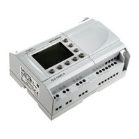
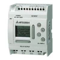
- AL2-24MR-A
Manuals and User Guides for Mitsubishi AL2-24MR-A. We have 2 Mitsubishi AL2-24MR-A manuals available for free PDF download: Hardware Manual, Quick Start Up Manual
Mitsubishi AL2-24MR-A Hardware Manual (434 pages)
al2 Simple application controller
Brand: Mitsubishi
|
Category: Controller
|
Size: 5.88 MB
Table of Contents
-
English
9
-
Table of Contents
9
-
1 Introduction
11
-
Special Features of the
12
-
Α 2 Series System
12
-
Eng
13
-
-
Dimensions and each Part Name
14
-
System Configuration
15
-
Applicable Programming Software
15
-
-
2 Specifications
17
-
Power Supply Specification
17
-
Input Specification
18
-
Output Specification
20
-
General Specification
21
-
-
3 Installation
23
-
Installation Mounting Notes
23
-
DIN RAIL Mounting of Main Unit
24
-
Installation
24
-
Remove
24
-
-
Direct Mounting of Main Unit
25
-
Install Extension Module
25
-
-
4 Wiring
27
-
Installation Wiring Notes
27
-
Wire Size
28
-
Power Supply
29
-
AC Power Supply and Input Wiring
30
-
AL2-4EX-A2 Input Wiring
30
-
-
DC Power Supply and Input Wiring
31
-
DC Power Supply and Source («+» Common) Input Wiring Diagram
31
-
AL2-4EX Source («+» Common) Input Wiring Diagram
31
-
DC Power Supply and Sink («-» Common) Input Wiring Diagram
32
-
AL2-4EX Sink («-» Common) Input Wiring Diagram
32
-
Output Relay and Transistor Wiring
33
-
Relay Output Wiring Diagram Main Unit (AC And/Or DC)
33
-
Relay Output Wiring Diagram AL2-4EYR (AC And/Or DC)
34
-
Transistor Output (Source or «+» Common Only) Wiring Diagram AL2-4EYT
35
-
-
-
5 Terminal Layout
37
-
6 Al2-Eeprom-2
39
-
Installation
40
-
Simple Application Controllers
41
-
-
7 Al-232Cab
41
-
Introduction
41
-
External Dimensions
41
-
-
Connected to AL-232CAB Cable
42
-
-
8 Al2-Gsm-Cab
46
-
Introduction
46
-
External Dimensions
46
-
System Configuration with Using AL2-GSM-CAB
47
-
-
Installation
48
-
Remote Maintenace with a Modem
50
-
Recommended Modems
50
-
RS-232C Straight Cable between Modem and AL2-GSM-CAB
50
-
Modem Setting
51
-
-
Introduction
54
-
External Dimensions
54
-
Al2-Asi-Bd
54
-
System Configuration
55
-
-
Specifications
55
-
Wiring & Installation
56
-
Installation
56
-
Wiring
57
-
-
Slave Address Setting & Diagnostics
57
-
Setting Slave Address
57
-
Applicable Error Checks
57
-
-
-
10 Key, System Bit and Function Block Lists
58
-
Key Lists
58
-
System Bit Lists
59
-
Control Bit Lists
59
-
-
Function Block Lists
60
-
-
11 Diagnostics
64
-
Input Status Error
65
-
Output Status Error
65
-
TOP MENU Is Not Displayed
66
-
Cannot Enter Run Mode
67
-
Incorrect Clock Data
67
-
The «?» Appears on the Display
67
-
Cannot Use an Operation Key
68
-
Incorrect LCD Display
69
-
Memory Cassette Is Not Working Correctly
69
-
Cannot Communicate with the AS-Interface Master Module
70
-
Cannot Communicate with AL-PCS/WIN-E
71
-
-
-
Deutsch
83
-
1 Einleitung
85
-
Besonderheiten der Α 2-Steuerung
86
-
Verfügbare Modelle
87
-
Abmessungen und Bedienungselemente
88
-
Systemkonfiguration
89
-
Programmier-Software
89
-
-
2 Technische Daten
91
-
Ger
91
-
Spannungsversorgung
91
-
Eingänge
92
-
Ausgänge
94
-
Umgebungsbedingungen
95
-
-
3 Installation
97
-
Installationshinweise
97
-
Montage auf einer DIN Befestigungsschiene
98
-
Montage
98
-
Demontage
98
-
-
Direktmontage
99
-
Installation der Erweiterungsmodule
100
-
-
4 Verdrahtung
101
-
Hinweise zur Installationsverdrahtung
101
-
Kabelgröße und Spezifikationen
102
-
Spannungsversorgung
103
-
AC-Spannungsversorgung und Eingangsverdrahtung
104
-
AL2-4EX-A2 Eingangsverdrahtung
104
-
-
DC-Spannungsversorgung und Eingangsverdrahtung
105
-
DC-Spannungsversorgung und Source Eingangsverdrahtung (Gemeinsamer «+» Pol)
105
-
AL2-4EX Source-Eingangsverdrahtung (Gemeinsamer „+» Pol)
106
-
DC-Spannungsversorgung und Sink-Eingangsverdrahtung (Gemeinsame Masse)
107
-
AL2-4EX Sink Eingangsverdrahtung (Gemeinsame Masse)
108
-
-
Relais-/Transistor-Ausgangsverdrahtung
109
-
Relaisausgangsverdrahtung „Hauptmodul» (AC Und/Oder DC)
109
-
Relaisausgangsverdrahtung AL2-4EYR (AC Und/Oder DC)
110
-
AL2-4EYT Transistor-Ausgangsverdrahtung (nur Source <Gemeinsamer „+» Pol>)
111
-
-
-
5 Klemmenbelegung
113
-
6 Al2-Eeprom-2
115
-
Installation
116
-
-
7 Al-232Cab
117
-
Einleitung
117
-
Abmessungen
117
-
-
Verbindung mit dem Kabel AL-232CAB
118
-
-
8 Al2-Gsm-Cab
121
-
Einleitung
121
-
Abmessungen
121
-
Systemkonfiguration bei Verwendung des AL2-GSM-CAB
122
-
-
Installation
123
-
Fernwartung über ein Modem
125
-
Empfohlene Modems
125
-
RS-232C-Kabel zwischen Modem und AL2-GSM-CAB
125
-
Modemeinstellungen
126
-
-
-
9 Al2-Asi-Bd
129
-
Maße
129
-
Installation
131
-
Verdrahtung
132
-
Einstellung der Slave-Adresse und Fehlerdiagnose
132
-
Einstellung der Slave Addresse
132
-
Fehlerdiagnose
132
-
-
-
10 Tasten, System-Bit und Funktionsblock-Listen
133
-
Übersicht der Tastaturbelegung
133
-
System- und Kontroll-Bit-Liste
134
-
System-Bit-Liste
134
-
Kontroll-Bit-Liste
134
-
-
Liste der Funktionsblöcke
135
-
-
11 Fehleranalyse
139
-
Eingangsstatusfehler
140
-
Ausgangsstatusfehler
140
-
Hauptmenü wird nicht Angezeigt
141
-
Umschaltung in den Run-Modus nicht Möglich
142
-
Falsche Uhrzeit
142
-
Das „?» Erscheint IM Display
142
-
Die Funktionstasten können nicht Verwendet werden
143
-
Falsche LCD-Anzeige
144
-
Die Speicher-Kassette Arbeitet Fehlerhaft
145
-
Die Kommunikation mit dem AS-Interface-Master-Modul ist Gestört
146
-
Die Kommunikation mit dem AL-PCS/WIN-E ist Gestört
147
-
-
-
Français
157
-
1 Introduction
159
-
Fre-2
159
-
Modèles Disponiblesl
161
-
Dimensions Et Éléments de Commande
162
-
Configuration du Système
163
-
Logiciel de Programmation
163
-
-
2 Spécifications
165
-
Alimentation
165
-
Sorties
168
-
Caractéristiques Générales
169
-
-
3 Installation
171
-
Conseils Pour L’installation
171
-
Montage de L’unité Principale Sur Rail DIN
172
-
Installation
172
-
Enlèvement
172
-
-
Montage Direct de L’unité Principale
173
-
Installation du Module D’extension
174
-
-
4 Câblage
175
-
Remarques Sur Le Câblage de L’installation
175
-
Dimension des Câbles
176
-
Alimentation
177
-
Câblage de L’alimentation CA Et de L’entrée
178
-
Câblage de L’entrée AL2-4EX-A2
178
-
-
Câblage de L’alimentation CC Et de L’entrée
179
-
Plan de Câblage de L’alimentation CC Et de L’entrée Source («+» Commun)
179
-
Plan de Câblage de L’entrée Source («+» Commun) AL2-4EX
179
-
Plan de Câblage de L’alimentation CC Et de L’entrée («-«)
180
-
Plan de Câblage de L’entrée Sink («-«) AL2-4EX
180
-
-
Câblage des Sorties Relais Et Transistors
181
-
Plan de Câblage de la Sortie Relais de L’unité Principale (CA Et/Ou CC)
181
-
Plan de Câblage de la Sortie Relais AL2-4EYR (CA Et/Ou CC)
182
-
Plan de Câblage de la Sortie Transistor (Source Ou Seulement «+» Commun)
183
-
Al2-4Eyt
183
-
-
-
5 Affectation des Bornes
185
-
6 Al2-Eeprom-2
187
-
Installation
188
-
-
7 Al-232Cab
189
-
Installation
189
-
Dimensions
193
-
-
-
8 Al2-Gsm-Cab
193
-
Introduction
193
-
Configuration du Système en Utilisant AL2-GSM-CAB
194
-
-
Installation
195
-
Installation du Modem
197
-
Modems Recommandés
197
-
Câble RS-232C entre Le Modem Et AL2-GSM-CAB
197
-
Réglages du Modem
198
-
-
-
9 Al2-Asi-Bd
201
-
Dimensions
201
-
Câblage Et Installation
203
-
Installation
203
-
Câblage
204
-
-
Réglage de L’adresse Esclave Et Diagnostics
204
-
Réglage de L’adresse Esclave
204
-
Contrôles À Effectuer en Cas D’erreur
204
-
-
-
10 Listes des Touches, Bits du Système Et Blocs de Fonctions
205
-
Listes des Touches
205
-
Listes des Bits du Système
206
-
Listes des Bits de Contrôle
206
-
-
Listes des Blocs Fonctions
209
-
-
11 Diagnostics
211
-
Erreur de L’état de L’entrée
212
-
Erreur de L’état de la Sortie
212
-
Menu Principal N’est Pas Affiché
213
-
Passage Dans Le Mode Run Impossible
214
-
Donnée D’horloge Incorrecte
214
-
Le «?» Apparaît Sur L’écran
214
-
Les Touches de Fonction Ne Peuvent Pas Être Utilisées
215
-
Affichage À Cristaux Liquides Incorrect
216
-
Cassette Mémoire Ne Fonctionne Pas Correctement
216
-
La Communication Avec Le Module Maître de L’interface as Est Perturbée
218
-
La Communication Avec AL-PCS/WIN-E Est Perturbée
219
-
-
-
Italiano
229
-
1 Introduzione
231
-
Le Speciali Caratteristiche del Sistema
232
-
Α 2 Sono
232
-
-
Modelli Disponibili
233
-
Misure E Nome Delle Singole Parti
234
-
Configurazione del Sistema
235
-
Software DI Programmazione Utilizzabile
235
-
-
2 Specifiche
237
-
Alimentazione DI Potenza
237
-
Ingress
238
-
Uscite
240
-
Specifica Generale
241
-
-
3 Installazione
243
-
Osservazioni Sull’installazione
243
-
BARRA DIN Montaggio Dell´unità Principale
244
-
Installazione
244
-
-
Montaggio Diretto Dell´unità Principale
245
-
Installare Il Modulo DI Estensione
246
-
-
4 Allacciamento Elettrico
247
-
Note Sul Cablaggio DI Installazione
247
-
Dimensione del Filo
248
-
Tensione DI Alimentazione
249
-
AC Circuito DI Alimentazione DI Corrente Ed Input
250
-
AL2-4EX-A2 Circuito DI Input
250
-
-
Circuito DI Alimentazione DI Corrente DC Ed Input
251
-
Diagramma Circuito DI Alimentazione DI Corrente DC E Fonte («+» Comune) DI Input
251
-
AL2-4EX Diagramma DI Fonte («+» Comune ) DI Input
251
-
Diagramma Alimentazione Corrente DC E Abbassamento («-» Comune) DI Input
252
-
AL2-4EX Diagramma Circuito Diminuzione («-» Comune) Input
252
-
-
Circuito DI Uscita Transistore E Relè
253
-
Diagramma Circuito DI Output del Relé , Unità Principale (AC E/O DC)
253
-
Diagramma Circuito DI Output del Relé , AL2-4EYR (AC E/O DC)
254
-
Diagramma Circuito Output del Transistore (Fonte/ «+» solo Comune)
255
-
Al2-4Eyt
258
-
-
-
6 Al2-Eeprom-2
259
-
Installazione
260
-
-
Sistema Α
261
-
7 Al-232Cab
261
-
Introduzione
261
-
Misure D’ingombro
261
-
-
Collegare al Cavo AL-232CAB
262
-
-
8 Al2-Gsm-Cab
265
-
Introduzione
265
-
Misure D’ingombro
265
-
Configurazione del Sistema con L´uso DI AL2-GSM-CAB
266
-
-
Installazione
267
-
Manutenzione Remota con un Modem
269
-
Modem Consigliati
269
-
Cavo Dritto RS-232C Fra Modem E AL2-GSM-CAB
269
-
Regolazione del Modem
270
-
-
-
9 Al2-Asi-Bd
273
-
Introduzione
273
-
Dimensioni Esterne
273
-
Configurazione del Sistema
274
-
-
Specifiche Tecniche
274
-
Cablaggio E Installazione
275
-
Allacciamento Elettrico
276
-
-
Impostazione Dell’indirizzo Secondario E Diagnosi
276
-
Impostazione Dell’indirizzo Secondario
276
-
Controlli DI Errore Applicabili
276
-
-
-
10 Elenchi Dei Tasti, Dei Bit del Sistema E del Blocco DI Funzione
277
-
Elenchi Dei Tasti
277
-
Elenco Bit del Sistema
278
-
Elenchi Bit DI Sistema
278
-
Elenco Bit DI Controllo
278
-
-
Elenchi Blocchi DI Funzione
279
-
-
11 Diagnostica
283
-
Errore Stato DI Input
284
-
Errore Stato DI Output
284
-
TOP MENU Non È Visualizzato
285
-
Non si Può Attivare Il Modo «Run
286
-
Dati Orologio Errati
286
-
Lo «?» Appare Sul Display
286
-
Non si Può Usare un Tasto Operativo
287
-
Display LCD Errato
288
-
La Cassetta DI Memoria Funziona Male
288
-
Non si Puó Comunicare con Il Modulo Master Dell´interfaccia as
289
-
Non si Può Comunicare con AL-PCS/WIN-E
290
-
-
-
Español
299
-
1 Introducción
301
-
Las Características Especiales del Sistema Α 2 Son
302
-
Modelos Disponibles
303
-
Dimensiones y Denominación de las Partes
304
-
Configuración del Sistema
305
-
Software de Programación Aplicable
305
-
-
2 Epecificaciones
307
-
Especificación de Carácter General
307
-
Entradas
308
-
Salidas
310
-
Especificación General
311
-
-
3 Instalación
313
-
Observaciones sobre el Emplazamiento
313
-
CARRIL DIN Montaje de la Unidad Principal
314
-
Instalación
314
-
Desmontaje
314
-
-
Montaje Directo de la Unidad Principal
315
-
Instalación del Módulo de Extensión
316
-
-
4 Alambrado
317
-
Notas sobre Los Alambres de Instalación
317
-
Tamaño de Cable
318
-
Alimentación de Tensión
319
-
Cableado de la Alimentación CA y la Entrada
320
-
Cableado de la Entrada AL2-4EX-A2
320
-
-
Cableado de la Alimentación CC y la Entrada
321
-
Esquema de Cableado de la Alimentación CC y Fuente de Poder (Terminal «+»)
321
-
Esquema de Conexión de Entrada de la Fuente de Poder AL2-4EX (Terminal «+»)
321
-
Esquema de Conexión de Entrada de Alimentación CC y Drenaje (Terminal «-«)
323
-
Esquema de Conexión de Entrada de Drenaje AL2-4EX (Terminal «-«)
323
-
-
Cableando las Salidas de Relé y de Transistor
324
-
Esquema de Conexión de Salida de Relé de la Unidad Principal (CA Y/O CC)
324
-
Esquema de Conexión de Salida de Relé AL2-4EYR (CA Y/O CC)
325
-
Salida de Transistor (Fuente de Poder O sólo Terminal «+») AL2-4EYT
326
-
-
-
5 Ocupaciones de Bornes
328
-
6 Al2-Eeprom-2
330
-
Installation
331
-
-
7 Al-232Cab
332
-
Introducción
332
-
Dimensiones Externas
332
-
-
Conectado con un Cable AL-232CAB
333
-
-
8 Al2-Gsm-Cab
336
-
Introducción
336
-
Dimensiones Externas
336
-
Configuración del Sistema Usando AL2-GSM-CAB
337
-
-
Instalación
338
-
Mantenimiento a Distancia Mediante un Módem
340
-
Módems Recomendados
340
-
Cable Directo RS-232C entre el Módem y AL2-GSM-CAB
340
-
-
-
9 Al2-Asi-Bd
344
-
Introducción
344
-
Dimensiones Externas
344
-
-
Conexionado E Instalación
346
-
Instalación
346
-
Alambrado
347
-
-
Asignación de Direcciones al Esclavo y Diagnóstico
347
-
Asignación de Direcciones al Esclavo
347
-
Comprobaciones a Realizar en Caso de Error
347
-
-
-
10 Listas de Teclas, Bits de Sistema y Bloques de Función
348
-
Listas de Teclas
348
-
Listas de Bits de Sistema
349
-
Listas de Bit de Sistema
349
-
Lista de Bit de Control
350
-
-
-
11 Diagnósticos
354
-
Ierror de Estado de Entrada
355
-
Error de Estado de Salida
355
-
El MENÚ PRINCIPAL no Se Visualiza
356
-
No Se Puede Ingresar al Modo Funcionamiento
357
-
Datos del Reloj Incorrectos
357
-
En el Visualizador Aparece
357
-
No Se Puede Usar una Tecla de Operación
358
-
Visualizador de Cristal Líquido Incorrecto
359
-
La Casete de Memoria no Funciona Correctamente
359
-
No Se Puede Comunicar con el Módulo Maestro de la Interfaz as
361
-
No Se Puede Comunicar con AL-PCS/WIN-E
362
-
-
-
Svenska
373
-
1 Inledning
375
-
Egenskaper Och Funktioner Hos Α 2-Serien
376
-
Modeller
377
-
Mått Och Benämningar
378
-
Systemkonfiguration
379
-
Kompatibla Programmeringsgränssnitt
379
-
-
2 Tekniska Data
381
-
Strömförsörjningskrav
381
-
Ingångsdata
382
-
Data För Utgångar
384
-
Allmänna Data
385
-
-
3 Installation
387
-
Installations- Och Monteringsanvisningar
387
-
Montering Av Huvudenheten På DIN-Skena
388
-
Montering
388
-
Demontering
388
-
-
Direktmonteing Av Huvudenheten
389
-
Installation Av Utbyggnadsmodul
390
-
-
4 Anslutning Och Kablage
391
-
Installations- Och Kablageanvisningar
391
-
Ledararea
392
-
Strömförsörjning
393
-
Växelströmsförsörjning Och Ingångskablage
394
-
Ingångskablage, AL2-4EX-A2
394
-
-
Likströmsförsörjning Och Ingångskablage
395
-
Kretsschema För Likströmsförsörjning Och Source-Ingång (Gemensam +)
395
-
Kretsschema För Source-Ingångskablage (Gemensam +), AL2-4EX
395
-
Kretsschema För Likströmsförsörjning Och Sink-Ingång (Gemensam -)
396
-
Kretsschema För Sink-Ingångskablage (Gemensam -), AL2-4EX
396
-
-
Kretsschema Utgångsrelä Och Transistor
397
-
Kretsschema För Reläutgång Huvudenhet (VäxelströM Och/Eller LikströM)
397
-
Kretsschema För Reläutgång AL2-4EYR (VäxelströM Och/Eller LikströM)
398
-
Kretsschema För Transistorutgång (Endast Source Eller Gemensam +)
399
-
Al2-4Eyt
399
-
-
-
5 Plintlayout
401
-
6 Al2-Eeprom-2
403
-
Installation
404
-
-
7 Al-232Cab
405
-
Yttre Mått
405
-
Ansluten Till AL-232CAB-Kabel
406
-
-
8 Al2-Gsm-Cab
409
-
Yttre Mått
409
-
Systemkonfiguration Med AL2-GSM-CAB
410
-
Fjärrunderhåll Via Modem
413
-
Rekommenderade Modem
413
-
RS-232C Rak Kabel Mellan Modem Och AL2-GSM-CAB
413
-
Modeminställning
414
-
-
-
9 Al2-Asi-Bd
417
-
Yttre Mått
417
-
Tekniska Data
418
-
Kabelanslutning Och Installation
419
-
Anslutning Och Kablage
420
-
-
Slavadressinställning Och Diagnostik
420
-
Slavadressinställning
420
-
Tillämpliga Felkontroller
420
-
-
-
10 Lista Över Knappar, Systembitar Och Funktionsblock
421
-
Lista Över Knappar
421
-
Lista Över Systembitar
422
-
Lista Över Kontrollbitar
422
-
-
Lista Över Funktionsblock
425
-
-
11 Diagnostik
427
-
Ingångsstatusfel
428
-
Utgångsstatusfel
428
-
TOP MENU Visas Inte
429
-
Det Går Inte Att Gå Över Till Driftläge
430
-
Felaktiga Klockdata
430
-
Ett Frågetecken, ?, Visas I Teckenfönstret
430
-
Kontrollknapparna Fungerar Inte
431
-
LCD-Fel
432
-
Minneskassetten Fungerar Inte Korrekt
432
-
Kommunikationen Med AS-Gränssnittets Mastermodul Fungerar Inte
433
-
Kommunikationen Med AL-PCS/WIN-E Fungerar Inte
434
-
-
Advertisement
Mitsubishi AL2-24MR-A Quick Start Up Manual (44 pages)
Alpha series;
Alpha2 series
Brand: Mitsubishi
|
Category: Controller
|
Size: 1.68 MB
Table of Contents
-
Important Features of the Mitsubishi Alpha
2
-
Mitsubishi Alpha Models and Expansion Modules
3
-
How to Wire Your Alpha’s Power Supply, Inputs and Outputs
4
-
100V AC — 240V AC Power Supply, Inputs and Outputs
4
-
24V DC Power Supply, Inputs and Outputs
5
-
Wiring Sourcing DC Input Terminals
5
-
Wiring Sinking DC Input Terminals
5
-
Wiring the Output Terminals
6
-
A Quick Introduction to Programming the Alpha
7
-
Some Commonly Used Logic Blocks
7
-
How to Program Your Alpha Using the Front Keypad and LCD Screen
8
-
How to Set the Alpha’s Time and Date Using the Keypad
8
-
How to Enter Run, Stop and Programming Mode
9
-
How to Choose a Function Block and Connect to an Input
10
-
How to Set up a Function Block
11
-
How to Connect a Function Block to an Output
12
-
How to Disconnect a Function Block
12
-
How to Remove a Function Block
13
-
A Quick Introduction to Visual Logic
14
-
How to Install Visual Logic on Your PC
14
-
Visual Logic Programming Environment
15
-
The Function Block Diagram (FBD) Window
16
-
Creating a Program
16
-
Simulating a Program
16
-
Monitoring a Program
16
-
The System Sketch Monitoring Window
17
-
Drawing Your Plant
17
-
Visual Logic’s Modes
18
-
Programming Mode
18
-
Simulation Mode
19
-
Monitor Mode
19
-
How to Write a Simple Program Using Your PC and Visual Logic
20
-
Create a Program
21
-
Simulate Your Program
23
-
Configure Your COM Port
23
-
Download and Monitor Your Program
24
-
How to Run a Program on Your Controller from Visual Logic
25
-
How to Stop a Program on Your Controller from Visual Logic
25
-
Read a Program from the Controller to Your PC
25
-
How to Write a more Complex Program Using Your PC and Visual Logic
26
-
An Example Program for Manual/Automatic Ventilation Fan
29
-
An Example Program for Time Switched Lighting
33
-
Car Park Lighting
37
-
The Program You’ve Created will
37
-
Table of Contents
38
-
Converting Ladder Logic to Alpha Logic and Function Blocks
38
-
Negative Logic (NOT)
38
-
Positive Logic
38
-
Or
39
-
-
And
39
-
Nand
40
-
Nor
40
-
Xor
41
-
On Delay Timer
41
-
One Shot Timer
41
-
Flicker
42
-
Set Reset
42
-
Comparison
42
-
Arithmetic
43
Advertisement
Related Products
-
Mitsubishi AL2-24MR-D
-
Mitsubishi AL2-14MR-A
-
Mitsubishi AL2-14MR-D
-
Mitsubishi AL-20MR-A
-
Mitsubishi AL-20MR-D
-
Mitsubishi AL2-10-MRA
-
Mitsubishi AL2-10-MRD
-
Mitsubishi AL-20MT-D
-
Mitsubishi AL2 Series
-
Mitsubishi AL-232CAB
Mitsubishi Categories
![]()
Air Conditioner
Controller
![]()
Projector
Automobile
Engine
More Mitsubishi Manuals
Изображение 1 из 11
Количество:
Более 10 в наличии
/
Продано: 30
Трендовый товар.
Продано: 30
Вздохните с облегчением.
Возврат товаров допустим.
Не отправляет товар в: Российская Федерация
.
См. подробнеео доставке
Находится в: ShenZhen, Китай
30-дневный возврат товаров
.
Покупатель оплачивает доставку возвращаемого товара
.
См. подробнее— дополнительная информация о возвратах
Покупайте с уверенностью
Сведения о продавце
- Положительных отзывов: 98,2%
Характеристики товара
В открытой коробке: Новый, неиспользованный товар без единого признака износа. Товар может быть без …
Hygrometer/Humidity, Temperature
Описание товара, предоставленное продавцом

Подробные оценки продавца
Средняя оценка за последние 12 месяцев
Разумная стоимость доставки
5.0
Другие находки:
(скачивание инструкции бесплатно)
Формат файла: PDF
Доступность: Бесплатно как и все руководства на сайте. Без регистрации и SMS.
Дополнительно: Чтение инструкции онлайн

AL802
Термометр с измерением комнатной и уличной
температуры, комнатной влажности и часами
Руководство пользователя
Slim Thermo-Hygrometer
User Manual
Страница:
(1 из 
навигация
Оглавление инструкции
- Страница 1 из 9
AL802 Термометр с измерением комнатной и уличной температуры, комнатной влажности и часами Руководство пользователя Slim Thermo-Hygrometer User Manual - Страница 2 из 9
AL802 Термометр с измерением комнатной и уличной температуры, комнатной влажности и часами РУКОВОДСТВО ПОЛЬЗОВАТЕЛЯ Раздел 1. Свойства Спасибо за то, что выбрали устройство производства компании Еа2 — мы стараемся сделать Вашу жизнь комфортней Thank you for choosing Ea2 Product and it is our - Страница 3 из 9
2. Основное устройство 1. Свойства 1.1 Время — Выбор типа отображения времени — 12/24 — Функция двойного будильника — Календарь до 2069 года — Выбор языка для дней недели 1.2 Температура — Диапазон измерения комнатной температуры : 0°C … +50°C — Выбор единицы измерения температуры °C / °F — - Страница 4 из 9
Примечание: Передача данных осуществляется на расстояние до 30 м на от к р ы т о м п р о с т ра н с т ве . О т кр ы т о е п р ос т р а н с т во : ме с тн о с т ь бе з препятствий – зданий, деревьев, механизмов, линий электропередач и тп. Для достижения наилучшего качества передачи радиосигнала - Страница 5 из 9
6.2 Температура и влажность: • (1) Наружная температура — Выбор канала радиопередачи • Используйте кнопку «КАНАЛ» (“CHANNEL”) [B8] для просмотра данных от 3-х каналов радиопередачи. Схема последовательности переключений: Нажать кнопку «КАНАЛ» > Нажать кнопку «КАНАЛ» > Нажать кнопку «КАНАЛ» - Страница 6 из 9
• Функция часового пояса используется в странах, где местное время отличается от среднеевропейского, которое передается радиосигналом DCF. 8. Индикатор низкого заряда батарей • Если местное время опережает среднеевропейское на 1 час, то значение часового пояса необходимо выставить +1. При получении - Страница 7 из 9
11. Технические характеристики Термометр / гигрометр: Габариты: 80 х 158 х 19 мм Диапазон измеряемой температуры: 0°C … +50°C [32°F … +122°F] Единицы измерения температуры: °C или °F [по выбору] Диапазон измерения влажности: 20% … 99% Питание: 3 батарейки ААА (не в комплекте) Дистанционный датчик: - Страница 8 из 9
- Страница 9 из 9