- Manuals
- Brands
- iNetVu Manuals
- Controller
- 7000 Series
- User manual
-
Contents
-
Table of Contents
-
Bookmarks
Quick Links
®
iNetVu
7000 Series Controller User Manual
With SW/FW 7.5.8.0
The iNetVu
®
brand and logo are registered trademarks of C-COM Satellite Systems, Inc.
© Copyright 2009 C-COM Satellite Systems, Inc.
1-877-iNetVu6
www.c-comsat.com
May 27, 2015
Revision 1.48
Related Manuals for iNetVu 7000 Series
Summary of Contents for iNetVu 7000 Series
-
Page 1
® iNetVu 7000 Series Controller User Manual With SW/FW 7.5.8.0 The iNetVu ® brand and logo are registered trademarks of C-COM Satellite Systems, Inc. © Copyright 2009 C-COM Satellite Systems, Inc. 1-877-iNetVu6 www.c-comsat.com May 27, 2015 Revision 1.48… -
Page 2
C-COM Satellite Systems Inc. Page 2 of 164 This page is intentionally left blank. -
Page 3
This document contains information, which is protected by copyright. All rights reserved. Reproduction, adaptation, or translation without prior written permission is prohibited, except as followed under the copyright laws. Both the iNetVu ® and C-COM names and logos are registered trademarks of C-COM Satellite Systems Inc. -
Page 4
1. “Installation” is the physical mounting and wiring of the Satellite provider’s earth station on a vehicle or other stationary site in order to prepare for correct operation. Only Certified C-COM iNetVu installers may perform the installation and removal of an iNetVu ®… -
Page 5
Warning signs shall be posted at prominent locations on the earth station informing all persons of the danger of harmful radiation from the earth station while it is deployed or while in operation. 8. The iNetVu ® Mobile system may only be operated when the vehicle is stationary. -
Page 6: Table Of Contents
Installation ………………….18 6.1. Rack Installation ………………..18 6.2. iNetVu ® Software – Software and USB Driver Installation ……. 18 6.3. iNetVu Setup Wizard ………………22 6.4. Setup ………………….24 6.5. Serial RS232 Setup ………………24 ® 6.6. Existing iNetVu Mobile Platform Installation ………..
-
Page 7
DVB_P ………………..79 7.6.6.5. MOD ………………..79 7.6.6.6. SYS1 ………………..80 7.6.6.7. ERR ………………..80 ® iNetVu 7000 Series Software …………….81 8.1. Setup Wizard ………………..81 8.2. Navigating Menus ………………. 82 8.2.1. iNetVu Controls ………………82 8.2.2. Maintenance ……………….. 94 8.2.2.1. -
Page 8
C-COM Satellite Systems Inc. Page 8 of 164 8.2.6. Exit ………………….133 ® iNetVu 7000 Series Controller Web Interface……….134 9.1. Navigating Menus ………………134 9.2. Controls ………………….136 9.3. Configuration ………………..137 9.4. System Test ………………..138 9.5. About ………………….139 9.6. -
Page 9: Introduction
C-COM Satellite Systems Inc. Page 9 of 164 1. Introduction ® The iNetVu 7000 Series Controller is a one-box, one-touch solution for satellite auto- ® acquisition. Designed to interface with a number of Satellite Modems, iNetVu VSATs, and DVB-S/DVB-S2ACM Receivers, the iNetVu ®…
-
Page 10: Specifications
C-COM Satellite Systems Inc. Page 10 of 164 2. Specifications Dimensions: Width: 17.1” x Depth: 11.0” Height: 2.0” Weight: 9.9 lbs. (4.5 kg) Operating Temperature: -20°C to +50°C Elevation Output: 12VDC, 15A (Max.)/24 VDC, 8A Azimuth Output: 12VDC, 10A (Max.)/24 VDC, 6A Polarization Output: 12VDC, 3A (Max.)/24 VDC, 2A Power Consumption (Idle): 12VDC @ 1A /24 VDC @ 0.5A…
-
Page 11: Physical
Cable Motor Control Mobile Platform Cable Fig. 2: iNetVu® 7000 Series Front and Rear Panel Note: VDC Power Input feature is available in the 7000C and 7024C Models Only. See Appendix for VDC power input external cable connectivity wiring.
-
Page 12: Typical Connection Configuration
5. Typical Connection Configuration The typical connection configuration for each service will be the same regardless of the Satellite Modem / VSAT. However, the configuration parameters for Satellite Modem / VSAT Communication will differ depending on service. See iNetVu ® System Manual for configuration procedures corresponding to the service used.
-
Page 13: Typical Network Interface Connection
Fig. 3: iNetVu ® 7000 Controller Typical Connection Configuration *Recommended for proper grounding of iNetVu ® systems. Note: VDC Power Input feature is available in the 7000C and 7024C Models Only. See Appendix for VDC power input external cable wiring.
-
Page 14: Typical Usb Communication Interface
USB Cable * Ground Connection Fig. 4: USB Configuration Interface *Recommended for proper grounding of iNetVu ® systems. Note: VDC Power Input feature is available in the 7000C and 7024C Models Only. See Appendix for VDC power input external cable wiring.
-
Page 15: Typical Serial Communication Port Interface
Fig. 5: Serial RS232 Configuration Interface Serial Cable * Ground Connection *Recommended for proper grounding of iNetVu ® systems. Note: VDC Power Input feature is available in the 7000C and 7024C Models Only. See Appendix for VDC power input external cable wiring.
-
Page 16: Typical Connection — Pc Free
Power Cable * Ground Connection Fig. 6: iNetVu ® 7000 Series Controller PC Free Connection Configuration *Recommended for proper grounding of iNetVu ® systems. Note: VDC Power Input feature is available in the 7000C and 7024C Models Only. See Appendix for…
-
Page 17: System Diagram With Splitter
Network Cable Power Cable Fig. 7: iNetVu ® 7000 Series Controller with Splitter Configuration * Ground Connection *Recommended for proper grounding of iNetVu ® systems. Note: VDC Power Input feature is available in the 7000C and 7024C Models Only. See Appendix for…
-
Page 18: Installation
If you are installing the iNetVu 7000 Series Controller onto a rack, ensure that you use ® supporting rails or a shelf to support the weight of the iNetVu 7000 Series Controller, and use the provided “ears/brackets” to fasten the unit to the rack face.
-
Page 19
1. Install the software from the Memory Stick or from a downloaded file by double clicking on iNetVuSetup.exe and follow the installation wizard. Note: The Driver installation will be done in two stages. FTDI CDM Drivers and, USB Drivers. 2. Install the iNetVu 7000 Software and close when complete. -
Page 20
C-COM Satellite Systems Inc. Page 20 of 164 3. Install the FTDI USB Drivers and iNetVu USB Drivers. Both are required. Click “Extract” Click “Next” Click “Finish” 4. Click Next on “Device Driver installation Wizard” window. Two windows may appear one for FTDI and one for Legacy click Next on both. -
Page 21
Page 21 of 164 5. Now that the drivers and software package has been installed, connect the iNetVu 7000 Controller via USB to your PC. 6. Windows XP users will have to follow the new hardware wizard and let windows automatically install the drivers. -
Page 22: Inetvu Setup Wizard
6.3. iNetVu Setup Wizard 1. The first screen you will see is the new iNetVu Setup Wizard. You can choose to continue using the wizard or click NO to proceed to the iNetVu Mobile 7000 software. NOTE: It is recommended that you continue to the iNetVu Setup Wizard and confirm all required information is correct.
-
Page 23
3. Follow the on screen instructions to update the controller firmware. Once complete the wizard will resume. 4. You may wish to continue through the wizard to complete the controller configuration or verify the settings. You can switch to the iNetVu software at any time by right clicking and selecting Controls. -
Page 24: Setup
(setup Diagrams). Select connections that are best suited for your application. 2. Power on the iNetVu ® 7000 Series Controller. 3. Set your external PC IP on the same subnet as the iNetVu ® 7000 Series Controller (Default controller IP Address of the 7000 is 192.168.0.2) 4.
-
Page 25: Existing Inetvu Mobile Platform Installation
**Note: as a rule of thumb you should always be running the latest iNetVu Firmware version (version 7.5.8.0+ or greater) to get full functionality of the features. In some cases the latest boot loader (7.6.1.0 at time of document creation) is also required to compliment the software features.
-
Page 26
10. Once prompted if you would like to save the configuration, press the ‘↑’ button such that ‘Y’ is selected for “yes”, and press, “Enter”. That’s it. You have successfully completed the installation and setup of the iNetVu ® 7000 Series Controller and are ready to find satellite. -
Page 27: Inetvu ® Front Panel Operation
7. iNetVu Front Panel Operation 7.1. LED Definition Fig. 11: iNetVu 7000 Series Controller Front Panel LED Panel ® POWER Solid light indicates power is ON. MOTOR Flashes when any of the three motors are instructed to move. COMM / LOCK Indicates Communication between Controller and Modem, it also indicates communication between GPS and controller.
-
Page 28: Manual And Automatic Controls Button Operation
7.2. Manual and Automatic Controls Button Operation Fig. 12: iNetVu ® 7000 Series Controller Front Panel Buttons How to Find Satellite Press “FIND SAT” Button. iNetVu Mobile Platform will automatically attempt to locate, lock, peak and enable the system ®…
-
Page 29: Lcd Screen And Navigator Keypad Operation
C-COM Satellite Systems Inc. Page 29 of 164 How to Turn ON/OFF the Controller Turn off the AC power switch on the back panel of the iNetVu ® 7000 Series Controller. When using DC external power source, the DC input power ON/OFF is controlled by the external source.
-
Page 30: Front Panel Menu Navigation Tree
CR Fig. 14: iNetVu ® 7000 Series Controller LCD Menu Options *Note: These are not sub-menus and do not exist under the OPERATION menu. They are merely used to identify the different sub menu options under the OPERATION menu depending on the modem service that is configured.
-
Page 31: Opening Screen
TST INFO Fig. 16: LCD Main Menu MONITOR This menu branch allows the user to monitor the status of the iNetVu Mobile Platform, its components, and displays information concerning the iNetVu 7000 Series Controller and the Satellite Modem / VSAT.
-
Page 32: Monitor
(Modem and Beacon Receiver) Displays Modem status as well as the Beacon Receiver frequency and signal (if a beacon receiver is used) Displays IP of iNetVu 7000 Series Ethernet Port, and the VSAT modem (Gateway) Displays Subnet, and Gateway IP.
-
Page 33: Main
C-COM Satellite Systems Inc. Page 33 of 164 7.6.1.1. MAIN This branch menu displays the real-time Elevation, Azimuth, Polarization Angles, their respective limits (Up, Down, Stow), the RF Receive Signal, Signal Strength, and the System Status. E-90.0 U D S A -45.7 S VV ST P-34.6 S…
-
Page 34
C-COM Satellite Systems Inc. Page 34 of 164 3 – Polarization Angle and Stow Limit Indicator 740/950/980 Mobile Platform Range: -70 to 70 1500/1800 Mobile/Flyaway Platform Range: -90 to 90 1200 Mobile Platform Range -90 to 90(ST at +65˚) 981/1201 Drive-away Platform Range: -90… -
Page 35
C-COM Satellite Systems Inc. Page 35 of 164 8 – Beacon Receiver Signal This section represents the strength of the Beacon Receiver Signal (if used). The letter ‘U’ next to the Beacon Signal indicates an unlocked status, whereas the letter ‘L’ next to the Beacon Signal indicates a Locked on satellite status. -
Page 36
5 — Elevation Offset ® The number of degrees at which the iNetVu Mobile Software will offset the reading from the Inclinometer in order to produce an accurate (+/- 2°) Elevation Angle (e.g. O: 31 implies elevation offset of 31). -
Page 37
4 – Z (AZ Zero) ® AZ Zero is an A/D value from the potentiometer which physically determines where the iNetVu Mobile Software places Azimuth Angle 0°. The AZ Zero may vary approximately +/-15% from the Default values (see Appendix). -
Page 38
4 – Z (PL Zero) PL Zero is a converted A/D value from the potentiometer and or a software generated fixed value from inclinometer that physically determines where the iNetVu ® Mobile Software places Polarization Angle 0°. The PL Zero may vary… -
Page 39
Platform is properly orientated. 4 — AZ Search Window Status The Search Window is the area of the sky which the iNetVu ® Mobile System will search for the desired Satellite. -
Page 40
6 – Transponder Symbol Rate (Ksps) 7 –Transponder Code Rate. DB-1 = 1/2 DB-2 = 2/3 DB-3 = 3/4 DB-5 = 5/6 DB-7 = 7/8 AUTO (DVB-S2 ACM SELECTION) 8 – Power Supplied to LNB from the 7000 Series Controller for the Target Satellite… -
Page 41
5 – Reference Satellite Transponder Symbol Rate (Ksps) 6 – Reference Satellite Transponder Code Rate. (DVBS1 requirement) DB-1 = 1/2 DB-2 = 2/3 DB-3 = 3/4 DB-5 = 5/6 DB-7 = 7/8 7 – Power Supplied to LNB from the 7000 Series Controller for the Reference Satellite… -
Page 42
2 – Beacon Receiver Frequency and Signal Strength The Beacon Receiver is an optional unit that could be used to acquire satellite with the 7000 Series Controller. See “iNetVu User Manual – Beacon Receiver” (7000 Controller section) for details 7.6.1.9.1 Hughes Modem Status (Only) -
Page 43
5 – Beacon Receiver Frequency and Signal Strength The Beacon Receiver is an optional unit that could be used to acquire satellite with the 7000 Series Controller. See “iNetVu User Manual – Beacon Receiver” (7000 Controller section) for details 7.6.1.10. IP This menu displays the IP address of the user configured iNetVu ®… -
Page 44: Operation
C-COM Satellite Systems Inc. Page 44 of 164 7.6.2. OPERATION TE TD AZ PL CM CA CR Fig. 28: Default Operation Menu Note: The OPERATION sub menu items may differ for Ka services. The satellite numbers (SS0, SS2, etc…) will be replaced with GPS location Beam Colors for Tooway or Beam ID for HN_KA.
-
Page 45
If the Antenna is already pointed on the satellite, clicking Find Satellite will re- peak or re-deploy the Antenna onto the last satellite signal found. There are 5 configurable satellites in the 7000 Series Controller (S0-S4) and each is now capable of having 5 configurable beacon settings. Press “Enter” onto the corresponding satellite, Beam Color or Beam ID to begin search. -
Page 46
C-COM Satellite Systems Inc. Page 46 of 164 4 –Azimuth Calibration (AZ) This feature will only be available on Legacy mounts. All new generation platforms (i.e. Ka-75V, 98H/98G/98V, 1201 etc…) will have this option disabled by default. Performs a complete Azimuth Calibration. … -
Page 47
C-COM Satellite Systems Inc. Page 47 of 164 recommended that you use an external compass to be as accurate as possible with the orientation. Note: The New Generation Platforms (these include and not limited to ka- 75V, 98H/98G/98V and 1201A) are equipped with newer versions of the compasses which are factory calibrated and do not require calibration in the field unless performed by C-COM support authorization only. -
Page 48: Conf1
This Menu will allow the user to configure and save all 5 Satellites with 5 beacon settings ® as well as other configurable Search Modes of the iNetVu System. A description of each menu and their purpose is outlined below. This section explains the different sub- menus of the configuration (CONF1) menu, and what each field parameter means.
-
Page 49
C-COM Satellite Systems Inc. Page 49 of 164 Allows the user to configure and save the Orbital slot / Longitude of the desired Target Satellite (0-4 satellites), along with the corresponding DVB Transponder and LNB Power Requirement. 5 satellites can be configured and saved with different search parameters Allows the user to configure and save the search mode (RF Search or DVB mode), Compass, RF Threshold and AZ search window. -
Page 50
Fig. 34: RF Cable Setup for DIS selection 7000 Series Controller Power Output Range Option Capabilities: 13, 14, 18, 19, V @ 500mA (max). If the user chooses to power the LNB from the controller, he/she should verify the power/voltage range requirements of the LNB in use, ®… -
Page 51: Sm1
TST. 4 — AZ Search Window ® The Search Window is the area of the sky which the iNetVu Mobile System will search for the desired Satellite. It uses a rectangular window and searches for the Satellite using smaller concentric windows until the desired Satellite is found.
-
Page 52: Sm2
A step-by-step procedure of how to configure the system is explained in the corresponding Service Provider Based Quick Start User Manuals. Please refer to the manual based on the service you are using with the 7000 Series Controller.
-
Page 53: Configuration Menu (Conf2)
C-COM Satellite Systems Inc. Page 53 of 164 7.6.4.1. Configuration Menu (CONF2) Password must be entered before accessing CONF2 menu and submenu. PL GP IP SR Fig. 37: CONFIG2 (Configuration) Menu (Reference Satellite Option Use Only) Allows the user to configure the Orbital slot / Longitude of a reference satellite, along with the corresponding DVB Transponder and LNB Power Requirement.
-
Page 54
C-COM Satellite Systems Inc. Page 54 of 164 7.6.4.2. This menu allows for the configuration of the reference satellite parameters. If the user is using the Reference Satellite Search option, the transponder information must be entered along with the LNB power requirements of the reference satellite used. The controller will lock onto the Reference satellite DVB carrier, and will pivot to the target satellite position to peak on the modem signal. -
Page 55
Fig. 39: RF Cable Setup for DIS selection 7000 Series Controller Power Output Range Option Capabilities: 13, 14, 18, 19, V @ 500mA (max) If the user chooses to power the LNB from the controller, he/she should verify the ®… -
Page 56
C-COM Satellite Systems Inc. Page 56 of 164 7.6.4.3. 0990.0 30000000 BRR :1210.99/22.0 Fig. 40: “S2” (Reference Satellite) Configuration Display 1 – Configured Satellite Modem Receive Frequency in MHz with no decimals. (HNS Only) 2 – Configured Satellite Modem Symbol Rate in sps. (HNS Only) 1Msps = 1000 Ksps = 1 000 000 sps 3 –… -
Page 57
It is the number of degrees at which the ® iNetVu Mobile Software will offset the reading from the Inclinometer in order to produce an accurate (+/- 2°) Elevation Angle. The user may set the offset with the range of 15º-55º, although altering this number from its default value may… -
Page 58
Mobile platform. 5 – Elevation Search Window The Search Window is the area of the sky which the iNetVu ® Mobile System will search for the desired Satellite. It uses a rectangular window and searches for the Satellite using smaller concentric windows until the desired Satellite is found. -
Page 59
1 – Configurable AZ Zero (Pot) AZ Zero is an A/D value from the potentiometer calculated upon azimuth ® calibration which physically determines where the iNetVu Mobile Software places Azimuth Angle 0°. The AZ Zero may vary approximately +15% from the Default values (see Appendix 1). -
Page 60
Page 60 of 164 3 — Stow Limit ® Enabling this function allows for the iNetVu system to trigger the stow limit when the mechanical stow range of the azimuth is reached. Disabling this limit, may result in failure to initiate the automatic stow command. -
Page 61
“PL (Polarization ) Configuration 1 – PL Zero PL Zero is used to convert the A/D value from the potentiometer that physically determines where the iNetVu ® Mobile Software places Polarization Angle 0. The potentiometer PL Zero may vary approximately +15% from the default values (see Appendix 1). -
Page 62
Current Limit, an error message will appear. For Motor Speeds that are not listed (Speed 1, 2, 4, 5, 7, 8), the Current Limit for those speeds is calculated using a percentage of the Current Limit above it. See Appendix 1 for the default current limits for all iNetVu ® Mobile Platforms. -
Page 63
“C1” Controller Display Screen 1 1 – B (iDirect TX Broadcast) The 7000 Series Controllers can be configured to broadcast with iDirect service. This allows iDirect users with broadcast configured modems, to lock onto a DVB carrier, and enable the transmitter in the iDirect modem automatically after peaking through the 7000 Series Controller. -
Page 64
This feature must not be used when the iNetVu system is being moved around or in transport mode. In this case, the system should be powered off completely. Otherwise, there is a risk of the antenna attempting to deploy while vehicle is moving. -
Page 65
D — Disabled E — Enabled 7 – DHCP Status The 7000 Series Controllers can be programmed to obtain an IP address from a DHCP Server (i.e. modem, router, etc.) D – DHCP Disabled (IP must be entered statically) E – DHCP Enabled (Controller will dynamically obtain an IP address from the DHCP Server) -
Page 66
Fig. 47: Controller Configuration (Screen 2) 1 – Console Port Configuration Used for the configuration of the console port of the 7000 Series Controllers. The Console port could be used for the following: 1) MDM (Modem Communication) If the COM port is used to establish communication between the Controller and the VSAT Modem (i.e. -
Page 67
The default baud rate is 9600. 2- Platform Type The user is capable of configuring the platform type using iNetVu LCD panel, as well as entering the serial number of the platform located next to the connector plate or on the elevation arm on the platform itself (only the last four or five digits need be entered). -
Page 68
This field allows the user to place a fixed offset for the target polarization angle. This value could make up for any noticeable mechanical offsets in the polarization assembly of the iNetVu platform between -5º to +5º. e.g. 1) Calculated Target Polarization Angle = 10º… -
Page 69
The user may change this password by using the “↓” and “↑” buttons on the front panel of the 7000 Series controller and the “→” and “←” buttons to navigate through the character fields. This password must be remembered in order for the user to re-enter the LCD screen configuration interface, or the web interface. -
Page 70
Fig. 50: “GW” (Gateway) Configuration 1 – S_IP (iNetVu ® 7000 Series Controller’s Subnet Mask IP Address – Default is (255.255.255.0) – Gateway IP Address (Default: 192.168.0.1) this can be changed to support the network you are on. 7.6.4.12. IP This menu will allow the user to configure the controller IP address, as well as the Modem IP address. -
Page 71
1 – Two-Way Mobile Service Selection Before communication is established with the modem, the user must define the service in use. The iNetVu ® 7000 Series Controller supports several services, including: ID – iDirect Service IS – iPSTAR Service VA – ViaSat Service VA –… -
Page 72: Tst
C-COM Satellite Systems Inc. Page 72 of 164 HT — HTTP Interface SN – SNMP Interface UD – UDP Interface NA — No modem interface applicable, this option is generally selected with the stand-alone service. Locking and peaking onto satellite is based on the DVB Signal and not on the modem SNR value. 3 –…
-
Page 73: E&A&P
C-COM Satellite Systems Inc. Page 73 of 164 M_ACP Performs a manual ACP test for Hughes service. S_ACP This operation will stop the ACP test from continuing. 7.6.5.1. E&A&P E +20:70:7 P-60: 60:7 A-180: 180:7 DD: D Fig. 54: Test/Demo EL,AZ, PL Configuration 1 –…
-
Page 74: Dpy
C-COM Satellite Systems Inc. Page 74 of 164 Infinitely loops with 15-seconds interval between tests. Infinitely loops with 18-seconds interval between tests. Infinitely loops with 21-seconds interval between tests. Infinitely loops with 24-seconds interval between tests. Infinitely loops with 27-seconds interval between tests. 5 –…
-
Page 75: Dpyq
C-COM Satellite Systems Inc. Page 75 of 164 7.6.5.3. DPYQ DPYQ deploys to the set angles excluding the fine tuning and pre-condition movement of EL to 30˚ as a first step. Note: See DPY for parameter functions and meanings as they are identical. E: +20 P+60 A +180…
-
Page 76
C-COM Satellite Systems Inc. Page 76 of 164 Antenna will move to the target Elevation, Polarization, and Azimuth for reading the compass heading such that the user can determine if the compass reading is accurate at that point. 7.6.5.5. RF :N-N-55-30N CP:V-0 AZ_W :60 1 –… -
Page 77: A_Acp
4 — AZ Search Window Status (value displayed but not used) ® The Search Window is the area of the sky which the iNetVu Mobile System will search for the desired Satellite. It uses a rectangular window and searches for the Satellite using smaller concentric windows until the desired Satellite is found.
-
Page 78: Cc1
7000 Series Controller to validate signal. 3 – 7000 Series Controller Board Hardware Type Version 4 – 7000 Series Controller Firmware and Boot loader version 7.5.8.0 The firmware version is to the left of the dash (i.e. — 7.6.1.0), and the boot loader version is 7.6.1.0…
-
Page 79: Dvb_D
This branch menu displays the controller DVB Module Type and ID. DVB-S2 (EA) – 0X3C Fig. 60: “DVB” (DVB Module) Display ® 1 – The DVB Module (Tuner) and ID currently embedded into the iNetVu 7000 Series Controller. 7.6.6.4. DVB_P This menu displays the real time DVB module information.
-
Page 80: Sys1
This branch menu displays the error code if an error occurs. The top line represents the latest error; the bottom line will represent any previous errors. Error INFO Fig. 62: “ERR” (ERROR) Display 1 – iNetVu ® Error code display…
-
Page 81: Inetvu ® 7000 Series Software
Mobile Software plays an integral role in connecting you and iNetVu ® Mobile System. The new addition of the iNetVu Setup Wizard will guide first time users and users that are already familiar with the software application to configure the system upon first launch.
-
Page 82: Navigating Menus
The Controls menu allows users to monitor system parameters and manually move the antenna, as well as conduct automatic processes and functions. Improper use of iNetVu Controls menu can render the iNetVu® Mobile System inoperable and may be in violation of FCC regulations. The user can halt…
-
Page 83
C-COM Satellite Systems Inc. Page 83 of 164 Fig. 63: Controls Window Signal Strength A real-time Signal Quality Factor (SQF). A value obtained from the Satellite Modem when locked onto a signal. Using a red/yellow/green color-coated system, it denotes the strength of the received signal from the current satellite. -
Page 84
C-COM Satellite Systems Inc. Page 84 of 164 Isolation Value Denotes isolation to the current satellite transponder. This value is not an indication of signal strength when transmitting a signal. The Isolation Value will correspond to the transmit quality of an HNS system. Otherwise, this field is not applicable. -
Page 85
C-COM Satellite Systems Inc. Page 85 of 164 position. Stop Operation Halts all motor movements and disrupts all communication between iNetVu ® Mobile System components. Orbital Slot Location of Configured Satellites The target and Reference satellites section displays the satellite longitude for each configured satellite. -
Page 86
Page 86 of 164 When the Elevation STOW Limit Indicator is ON, the Elevation Angle will change to “–90”, to denote that the iNetVu ® Mobile Platform is now stowed. It will remain “-90” until the indicator turns OFF. -
Page 87
C-COM Satellite Systems Inc. Page 87 of 164 Face Reflector this direction for correct Azimuth and Polarization Orientation Fig. 69: Orientation Reference for Azimuth and Polarization Enable/Disable Transmitter Automatically Enables or Disables the Transmission process. Background will turn grey when transmitter is disabled and green when the transmitter is enabled. -
Page 88
C-COM Satellite Systems Inc. Page 88 of 164 Fig. 71: Deploy Antenna Input Values Quick Deploy Automatically moves antenna to the manually entered Elevation, Azimuth and Polarization angles without first moving to 30˚ on Elevation. This process moves to the set angles without the extra angle tuning that occurs with the Deploy Antenna button. -
Page 89
C-COM Satellite Systems Inc. Page 89 of 164 configured and viewed on the Configuration screen. Antenna Latitude/Longitude GPS Coordinates acquired from the GPS Antenna or manually overridden values. EL Motor Current Current drawn for Elevation Motor (in Milliamps mA) AZ Motor Current Current drawn for Azimuth Motor (in Milliamps mA) PL Motor Current Current drawn for Polarization Motor (in Milliamps mA) -
Page 90
C-COM Satellite Systems Inc. Page 90 of 164 Target Polarization (Target PL) Calculated Polarization Angle that the Antenna must be in order to find the desired Satellite. Compass Heading Orientation of the Mobile Platform. This value is only read during the Find Satellite, Check Compass, and Calibrate Compass processes. -
Page 91
Flashing “RED” and “YELLOW” messages indicates a problem with that component. Should the entire Status Panel flash “RED” and or “YELLOW”, a communication failure between the PC and the iNetVu ® Controller has occurred. Ensure that the Controller is powered, and that all USB drivers and cables (USB, LAN or Serial) are installed properly. -
Page 92
C-COM Satellite Systems Inc. Page 92 of 164 Skew Adjusting Polarization adjustment to adjust the polarization axis for any vehicle inclination. The Azimuth Axis will rotate 90º on both sides of the peaked azimuth angle, then return to the satellite position, and adjust the polarization axes to compensate for any recognized mount inclination. -
Page 93
C-COM Satellite Systems Inc. Page 93 of 164 Controller Status ® Displays communication status between the PC and the iNetVu Controller Controller Normal Indicates normal communication status between the Controller and the PC Controller Failed A failure in communication between the Controller and the PC has been detected. -
Page 94: Maintenance
Ka platforms. Click SAVE ALL when any modifications are made, and before power recycling the controller to ensure data will be saved on controller side. Fig. 77: iNetVu ® 7000 Maintenance Window…
-
Page 95: Platform Parameters
Platform Parameters Fig. 78: Maintenance Platform Parameters Type The user is capable of configuring the platform in use. ® A0750A — iNetVu A750A (.75m) Mobile Platform (Ku Band) ® A0755A — iNetVu A0755A — New Gen Drive-Away (Ka Band circular) ®…
-
Page 96: Gps And Compass
C-COM Satellite Systems Inc. Page 96 of 164 Platform Serial Number The user will be required to enter the last four or five-digits of the platform serial number located next to the connector plate on the iNetVu ® Mobile Platform. Fig. 79:…
-
Page 97
GPS relocation can be detected. Moving vehicle speed must reach min 5km/h plus Elevation angle change of 2 degrees or more with GPS coordinates change in order for the movement protection feature to trigger. GPS Latitude This field represents the Latitudinal GPS coordinates of the iNetVu ® system. GPS Longitude This field represents the Longitudinal GPS coordinates of the iNetVu ®… -
Page 98
C-COM Satellite Systems Inc. Page 98 of 164 Disable Auto Calibrate Compass Offset If this option is unchecked the following will take place. Auto Calibration on compass occurs when the angle difference of 20 degrees or more is detected between AZ angle and System AZ Ref when the system finishes the satellite search routine and locks on signal. -
Page 99
Antenna will rotate 90 to each of the following positions and read the compass at each: 0, 90, 180, -90, 0 iNetVu ® Mobile Software will compare the compass heading values read at each position, and determine if they differ by approximately 90. -
Page 100: Elevation Parameters
The Elevation Offset is specific to each type of platform. It is the number of degrees at ® which the iNetVu Mobile Software will offset the reading from the Inclinometer in order to produce an accurate (+/- 2°) Elevation Angle.
-
Page 101
Platform’s elevation motors. For Motor Speeds that are not listed (Speed 1, 2, 4, 5, 7, 8), the Current Limit for those speeds is calculated using a percentage of the Current Limit ® @ speed 6 and 9. See Appendix 1 for the default current limits for all iNetVu Mobile Platforms. -
Page 102: Azimuth Parameters
Maintenance — Azimuth Parameters Zero Azimuth Zero is an A/D converted value from the potentiometer calculated upon azimuth calibration which physically determines where the iNetVu ® Mobile Software places Azimuth Angle 0°. In the new Generation systems, the potentiometer is replaced with an Encoder.
-
Page 103
The Current Limit for the speeds is calculated using a percentage of the Current Limit @ speed 6 and 9(current limit 6 @ speed 6 is default). See Appendix 1 for the default current limits for all iNetVu ® Mobile Platforms. -
Page 104: Polarization Parameters
Inclinometer Tilt Sensor which exists on all New Generation platforms and newer versions of the Legacy platforms. The Tilt Sensor is replacing the ® Potentiometer which physically determines where the iNetVu Mobile Software places Polarization Angle 0. The Zero value may vary approximately +/-15% from the default values for all platforms using potentiometers (see Appendix 1).
-
Page 105
Low Platform Current Low Platform Current is a software controlled current protection for the Mobile Platform’s polarization motors. See Appendix 1 for the default current limits for all iNetVu ® Mobile Platforms. -
Page 106: Pc Application
This checkbox is used to either enable or disable the beeping noise when navigating the ® LCD interface on the iNetVu 7000 Series Controller. Selected option implies beeping sound is enabled unless D (disabled) is selected. Disabled – Beep Disabled, the sound will be completely muted.
-
Page 107: Maintenance Menu Buttons
“iNetVu7000_SatParam” text file, into the 7000 Series Controller. The user may modify the table with any DVB transponders that he/she would like saved in the 7000 Series Controller, and click on this button to upload the changes to the controller.
-
Page 108
® Mobile Software *Save Config File Allows the user to save all configuration parameters of the iNetVu Controller Configuration into a txt file located in the iNetVu Mobile 7000 application folder. *Read Config File Will populate the maintenance and Configuration screens with the configurable parameters in the saved iNetVu7000_Config.txt file… -
Page 109: Configuration
The Configuration menu allows users to configure the communication medium between ® ® ® the Satellite Modem and iNetVu Mobile Software, iNetVu Controller and iNetVu Mobile Software, as well as various System parameters for optimal performance. Users have the ability to configure and save 5 Satellites (0-4) with their orbital slot and 5 Beacon frequency settings.
-
Page 110: Target Satellite Parameters
C-COM Satellite Systems Inc. Page 110 of 164 8.2.3.1. Target Satellite Parameters Fig. 88: Configuration – Satellite Parameters Satellite No. 5 different satellite parameters are configurable allowing users to configure and save for easy access. Priority order must be followed when saving, Satellite no. first and all other parameters afterwards.
-
Page 111
C-COM Satellite Systems Inc. Page 111 of 164 Use the following as reference for Sat pol Offset: Receive is vertical and Transmit is vertical – VV = 90 Receive is horizontal and Transmit is horizontal – HH = 0 e.g. 1) Receive is Vertical and Transmit is Horizontal (VH) — The offset entered should be 90, thus VH = 90. -
Page 112
Frequency (KHz), Code Rate, Symbol Rate (Ksps) The frequencies listed are in Ku-band. The user may select from the six (6) available transponders saved in the 7000 Series Controller, which are specific to each satellite, or he/she may also enter valid transponder data manually. -
Page 113: Reference Satellite Parameters
The reference satellite option is useful when the user cannot find a DVB transponder on the desired target satellite. The user may select a reference Beacon Frequency or a satellite with a known DVB Transponder. The iNetVu ® System will lock onto the reference satellite, and then pivot from that point to the desired target satellite, and peak on the modem signal.
-
Page 114: Modem Parameters
C-COM Satellite Systems Inc. Page 114 of 164 BR300L (Optional) This is a new feature which allows the use of the Beacon for the reference satellite search, works in the same manner as a Reference Satellite search would work. Enabling the Ref Sat Option and entering the parameters for the Beacon would allow the reference search to work on the Beacon Frequency.
-
Page 115
C-COM Satellite Systems Inc. Page 115 of 164 UDP – User Datagram Protocol NA – Used for standalone systems where only DVB or Beacon is used to lock onto a satellite without the use of a modem. Modem Delay The user may increase the delay time when polling for modem signal by adjusting this number. -
Page 116
C-COM Satellite Systems Inc. Page 116 of 164 Demodulator/Carrier (RADYNE MDX Modem Only) — Demodulator Number (1—4) — Remote Number on selected demodulator (1—8) Password/CD-KEY Some modems require a password to access their interface. For modems that do not require a password, this field is irrelevant to the communication status between the modem and the controller and will not affect the communication establishment. -
Page 117: Beacon Receiver
Beacon Receiver is not used, this field can be ignored. ACQ Attenuation (dB) The 7000 Series controller software interfaces give the user flexibility to set the power level of the signal when searching using the beacon receiver. This field is only related to…
-
Page 118: Controller Parameters
Default Gateway The Gateway IP address used by the iNetVu ® 7000 Series Controller. DHCP ® The iNetVu 7000 Series Controller could obtain a dynamic IP address from a DHCP Server (i.e. router, modem, etc.) if this option is enabled.
-
Page 119: Search Parameters
Override Compass Checkbox The Compass is pre-calibrated by a professional installer at the time of system installation or come pre-calibrated from the compass manufacturer. A number of factors can contribute to the iNetVu ® compass to produce an incorrect reading such as being parked in close proximity to a large metallic object. Should the compass heading be inaccurate by more than 20 degrees, you may need to re-calibrate or Restore it (Mount Dependent), or select “Override Compass”…
-
Page 120
After enabling Override, you may enter the vehicle’s direction as indicated on your ® alternate compass. Keep in mind that the base of the iNetVu Mobile Platform is oriented to the front of your vehicle (back of reflector and front of vehicle face the same direction) refer to orientation figures in this document. -
Page 121
C-COM Satellite Systems Inc. Page 121 of 164 IV. Select Full Search, this will hide override Compass and Direction, click on Save Fig. 95: Compass Full Search Configuration Parameters North — 354 West — 265 South -176 East — 87 This end is the reference for Vehicle Orientation, this end faces North This end faces South… -
Page 122
C-COM Satellite Systems Inc. Page 122 of 164 Using the image below as guidance example provided for reference. North (180˚) Location 1 West (90˚) East (-90˚) South (0˚) Facing Antenna Reference Example 1. There is an object at location 1 and we want to avoid this area. a.) Select direction to be NW (315˚) which will set System AZ Ref to 45˚… -
Page 123: Controller Feature
The RF Threshold can also be manually set to any value ranging from 40 to 60 which will display the true value of RF Signal on the iNetVu Controls window. Setting the RF Threshold to 30 will put the search into a step-through-search moving the AZ axis in small incremental steps, this method increases the search time.
-
Page 124
C-COM Satellite Systems Inc. Page 124 of 164 Movement Protection (not a selectable option) The movement protection option is always enabled and is embedded into the controller. System will stow automatically when vehicle begins to drive off. The movement protection feature will not function properly if the GPS is overridden because movement protection relies on change of GPS speed (min 5 km/h) plus a change of 2 degrees or more on Elevation. -
Page 125: Advanced Search Configuration
C-COM Satellite Systems Inc. Page 125 of 164 8.2.3.8. Advanced Search Configuration Fig. 97: Advanced Satellite Search Configuration options Multi-Sat Search Multiple satellite search allows the user to configure multiple satellites and search continuously on the configured satellites (SAT0, SAT1 or SAT2) if search on the first selected satellite fails, search will automatically start on the second configured satellite in the list.
-
Page 126: Lnb Lo & 22Khz Tone
C-COM Satellite Systems Inc. Page 126 of 164 Max ES/NO The Satellite peaking routine will stop at the set value of the SNR signal thus reducing the peaking time after reaching the highest set value. Modifying and or misconfiguring this parameter may inhibit satellite searching sequence and stop the peaking before reaching the highest possible signal.
-
Page 127: Com Port Interface
8.2.3.10. COM Port Interface This drop down menu allows the user to define the functionality of the serial interface on the iNetVu ® 7000 Series Controller. The following are the Interface options to select from: DEBUG — Used for internal debugging purposes.
-
Page 128: Maintenance Test
C-COM Satellite Systems Inc. Page 128 of 164 8.2.3.12. Maintenance Test Used for system tests, trouble-shooting, and for demonstrating the iNetVu ® Mobile System. This feature is accessible from the Maintenance Window Test button. Fig. 99: Demo and Test Window…
-
Page 129
Modem Test (Command) The user may enter certain modem commands, and click send. The 7000 Series Controller will then read the response from the modem in the text area below the command line. Currently the commands supported are for iDirect service: … -
Page 130: About
Controller’s firmware version. For compatibility purposes, Controllers are pre-configured with the appropriate firmware for the accompanied software version. Serial Number iNetVu ® Controller Serial Number ID. ® This field is supported for iNetVu Controller Firmware 4.2 and higher.
-
Page 131
C-COM Satellite Systems Inc. Page 131 of 164 Interface ® This field represents the means of communication between the iNetVu software, and the 7000 Controller. Bootloader Bootloader version loaded in the 7000 Series Controller Revision Indicates the revision number of the current Controller Hardware version … -
Page 132
Type of modem currently communicating with the controller Firmware Satellite Modem’s firmware version. Serial Number Satellite Modem’s Hardware ID or Serial Number. Interface Modem Interface to the iNetVu ® 7000 Series Controller. Satellite Longitude Modem target longitude value and hemisphere. RX Polarity… -
Page 133: Language
The multilingual feature allows the toggling between Four (6) languages and updates in real-time the selected language. Currently the available languages are English, Chinese (Simplified and Traditional), Spanish, Russian and Swedish with more to come. Fig. 102: iNetVu Controls Window in Chinese 8.2.6. Exit Close the running IMS 7000 Application.
-
Page 134: Inetvu ® 7000 Series Controller Web Interface
PC. Note some function(s) may not be available in Web interface i.e. Download Log File. 9.1. Navigating Menus To view the web interface, type in the IP address of the 7000 Series Controller in the web browser. There are 5 options available: …
-
Page 135
C-COM Satellite Systems Inc. Page 135 of 164 To reset the password, click on “RESET PWD”, and enter “123456789” for the reset ID. These options are available once the controller is in upload mode: Login Firmware Update Sat Table Update … -
Page 136: Controls
The main difference between the web interface and iNetVu Application is that the Compass Calibration (CP CAL), Compass Test (CP TEST), Azimuth Calibration (AZ CAL), and Polarization Calibration (PL CAL) are all in the iNetVu Controls web page, rather than the Maintenance menu.
-
Page 137: Configuration
Configuration window. The Configuration menu allows users to set the Satellite’s name and orbital slot, and override parameters as well as putting the controller in updating mode. The 7000 Series Controller Web Interface is similar to the iNetVu ® Software Configuration Menu (See Software Configuration Menu Section for More Details) Click SEND if any modifications are made.
-
Page 138: System Test
This screen is mainly used for Demos, testing certain components of the system, and for sending certain modem commands that have been integrated with the iNetVu ® 7000 Series Controller. The 7000 Series Controller Web Interface System Test web page is similar to the ® iNetVu Software Test Screen Fig. 107:…
-
Page 139: About
C-COM Satellite Systems Inc. Page 139 of 164 9.5. About The “iNetVu About” web page, displays information to the user about various sub-system components, as well as contact information for support and feedback. Fig. 108: Web Interface — About Screen…
-
Page 140: Firmware/Satellite Table Update
PC, press the “reset” button on the 7000 Series Controller, and hold the “↑” and “↓” buttons on the front panel at the same time until you read “Firmware/Sat update” on the LCD screen.
-
Page 141: Firmware Update
C-COM Satellite Systems Inc. Page 141 of 164 9.6.1. Firmware Update To update the controller firmware click on the “FIRMWARE UPDATE” link on the left panel. The following screen should appear: Fig. 110: Firmware Update Window To update the firmware via web page: 1.
-
Page 142: Satellite Table Update
C-COM Satellite Systems Inc. Page 142 of 164 9.6.2. Satellite Table Update In order to update the table containing the satellite transponder data, the iNetVu7000_SatParam.txt file must be manually changed. For example, If a user wishes to add a transponder to satellite 91W, he/she would locate satellite 91W in the table, and replace one of the transponders with the new transponder data.
-
Page 143: Controller Connectivity
® 7000 Software on your PC and place your PC on the same network as the 7000 Series Controller. In order to access the Web Interface, place your PC on the same network as the 7000 Series Controller, and simply type in the IP address of the 7000 Controller into your web browser.
-
Page 144: Network Configuration Example
Modem IP: 10.211.9.73 Fig. 116: Controller to Modem Network Setup ** Once the IP Address is assigned to the iNetVu ® 7000 Controller by the Satellite Modem / VSAT, you may check the LCD Menu to view the assigned IP Address.
-
Page 145: How To Set Network Configurations On Your Pc
Properties. 2. Select Internet Protocol (TCP/IP) and click Properties. 3. Direct Network Connection: ® Set your PC to the same subnet as the iNetVu 7000 Series Controller, and the Default Gateway to the iNetVu ® 7000 Series Controller.
-
Page 146: Integrations And Compatibility Features
11.1. GLONASS Navigation System The GLONASS Navigation System is now fully compatible with the 7000 series controller using the NAVIS Receiver Module, P/N: NV08C-EVK-CSM. To date this is the only module that has been successfully tested and thus only this device (P/N: NV08C- EVK-CSM) will be supported.
-
Page 147: Appendices
C-COM Satellite Systems Inc. Page 147 of 164 12. APPENDICES…
-
Page 148: Appendix 1: Default Limits And Configuration Data Tables
C-COM Satellite Systems Inc. Page 148 of 164 12.1. Appendix 1: Default Limits and Configuration Data Tables Compass Reading Elevation PLATFORM TYPES A1800A A1500A/ A1200 A0980 A0740 A0660 /B/C/E B/C/E COMPASS READING ELEVATION PLATFORM TYPES A1810A A1801A A0180A A1210A A1201A A1200Q /B/C/E /B/C/E…
-
Page 149
C-COM Satellite Systems Inc. Page 149 of 164 AZ Potentiometer/Encoder PLATFORM TYPES A1200B/ A1800A/B A1500A/ A0980 A0740 A0660 /C/E B/C/E AZ ZERO 280.7808 282.88 342.17 342.17 342.17 PLATFORM TYPES A1210A A1201A A1200Q A0981A A0755A AZ ZERO 282.8 210.9 282.8 282.8 A0985A/B A0121A A0125A… -
Page 150
C-COM Satellite Systems Inc. Page 150 of 164 Default Platform Speeds and Limits PLATFORM TYPES A1200B/ A1800A/ C/A1500 A0980 A0740 A0660 B/C/E A/B/C/E EL SLOW EL CURRENT6 7.00A 7.00 7.00 7.00 7.00 EL CURRENT9 12.00A 12.00 12.00 12.00 12.00 AZ SLOW AZ CURRENT6 7.00 7.00… -
Page 151: Appendix 2: Compass Direction And System Ref. Az Table
C-COM Satellite Systems Inc. Page 151 of 164 12.2. Appendix 2: Compass Direction and System Ref. AZ Table System Ref. Direction Search Window Starting Angle North (N) = 0 North West (NW) = 45 East (E) = 90 -135 South East (SE) = 135 -135 -180 South (S) = 180…
-
Page 152: Appendix 3: Lcd Table Summary
C-COM Satellite Systems Inc. Page 152 of 164 12.3. Appendix 3: LCD Table Summary Menu Field Explanation MONITOR MAIN Elevation Angle and Limit Indicators E (Angle) Azimuth Angle and Stow Limit Indicator A (Angle) P (Angle) – Polarization Angle and Stow Limit Indicator P (Angle) GPS Status Flag and Compass Status Flag (OO, OV, VO, FF) GPS and CMPS…
-
Page 153
C-COM Satellite Systems Inc. Page 153 of 164 T0-T2 (Horizontal Receive) and T3-T5 (Vertical Receive) DVB Transponders TP NUMBER Satellite Transponder Frequency that DVB searches for ref. Satellite FREQUENCY Satellite Transponder Symbol Rate that DVB searches for ref. Satellite SYMBOL RATE Satellite Transponder FEC (Code) Rate that DVB searches for ref. -
Page 154
C-COM Satellite Systems Inc. Page 154 of 164 Up, Down, and Stow Limits enabling (E) or disabling (D) on the Elevation Axis L (UDS) Compass Reading Elevation Angle C (EL Value) Slow Speed Settings for Elevation Angle Operation S (Value) Current Limits on EL Axis @ Speed 9 and @ Speed 6 I (Limits) AZ Pot Zero for converting A/D value for physical determination of AZ zero angle… -
Page 155
C-COM Satellite Systems Inc. Page 155 of 164 S_ACP Stops any Cross Pol testing in progress S_ACP INFO States the Controller ID ID (Value) States the Controller Board Hardware Type HW (Value) Signal Quality Threshold for proper Controller SNR Reading SQ_T (Value) States the Firmware and Boot loader version respectively FBV (FW –… -
Page 156: Appendix 4: Router Configuration Example
C-COM Satellite Systems Inc. Page 156 of 164 12.4. Appendix 4: Router Configuration Example iNetVu™ Mobile Platform Antenna *Ground protection External grounding connection RX IN 12/24 VDC Power Input SENSOR MOTOR CABLE CONTROL 7000 CTRL: DHCP Computer Static: 90 — 264VAC 192.168.1.3…
-
Page 157: Appendix 5: Tooway Look-Up Table
The following procedure will only work on Controllers with Hardware ID >= (greater or equal to) 1, this can be confirmed in the software “About” window. 1. Upload to Latest iNetVu FW. 2. Launch iNetVu Mobile 7000 Software. 3. Configure Application to use desired Platform i.e A0755A or A0985A (In Maintenance Window) and Modem type (In Configuration Window).
-
Page 158
C-COM Satellite Systems Inc. Page 158 of 164 6. In the Configuration Window, click on Update Look-up Table 7. This process will take approximately 6-10min depending on your system. Status will be displayed on the bottom of the Configuration window. Look-up Table Upload Look-up Table Upload Status… -
Page 159
C-COM Satellite Systems Inc. Page 159 of 164 8. The Upload status will be confirmed with an OK once it finishes. 9. Ensure Auto-select Beam Color option is selected on the Application side in order to see which Beam color the auto selection is searching on. 10. -
Page 160
C-COM Satellite Systems Inc. Page 160 of 164 12. Hold down the FIND SAT button for 3 seconds then let go, Tooway menu will display, which will allow the user to manually select the Beam Color they desire. BLU ORG PRP GRN SS4 TE TD AZC PLC CPC CR 13. -
Page 161: Appendix 6: Dc Input Power Cable Connectivity
C-COM Satellite Systems Inc. Page 161 of 164 12.6. Appendix 6: DC Input Power Cable Connectivity Note: DC Input connector exists in 7000C and 7024C controllers ONLY, older versions do not have the DC Input connector. Controller Receptacle External Cable Plug J1 Panel Receptacle P1 Straight Plug 4-Socket Contacts Mating View…
-
Page 162
C-COM Satellite Systems Inc. Page 162 of 164 Materials Required for External Cable: Part # Quantity Description 206429-1 TEConnectivity AMP CPC Plug Assembly, Shell Size 11, Reverse Sex, 4-Pin Contacts, Series 1 206358-5 TEConnectivity AMP CPC Cable Clamp, Size 11 66361-4 TEConnectivity AMP CPC Pin Contact, Series 1, Wire 18- 14 AWG… -
Page 163: Appendix 7: Declaration Of Conformity
(optional) Importers Address (optional) Type of Equipment Satellite Antenna Controller Model Number iNetVu Mobile System CE Marked 2005 Serial No. (Optional) Year of Manufacture (Optional) 2004 I, the undersigned, hereby declare that the equipment specified above conforms to the above Directives and Standards.
-
Page 164: C-Com Satellite Systems Inc
C-COM Satellite Systems Inc. Page 164 of 164…
КОРОТКО О НАС в цифрах:
>50
РАЗРАБОТАННЫХ ОТРАСЛЕВЫХ РЕШЕНИЙ “ПОД КЛЮЧ”
>200
ВЫПОЛНЕННЫХ ПРОЕКТОВ ПО ВСЕЙ РОССИИ
>7000
ПОДКЛЮЧЕННЫХ АБОНЕНТОВ
>100
ГОСУДАРСТВЕННЫХ ЗАКАЗА
4
ЛИЦЕНЗИИ НА УСЛУГИ СВЯЗИ

|
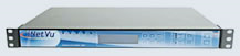
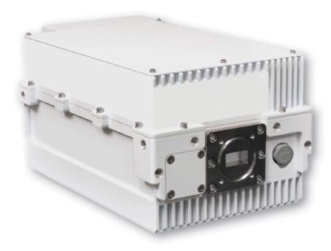
INetVu ® 7000 контроллер идеально подходит для приложений, которым требуется быстрая, простая установка и надежное соединение. Новый контроллер iNetVu ® 7000 имеет высокую точность наведения антенны, его передняя панель имеет удобную клавиатуру для конфигурации и LCD –дисплей, на задней панели имеется разъем для подключения GPS-сигнала для внешних устройств. Технические характеристики iNetVu 7000 |


Наши действующие лицензии
Телематические услуги связи |
Услуги связи по передаче данных |
Услуги связи по предоставлению каналов связи |
Отправить заявку в 3 клика
Остались вопросы?
можете
задать вопрос
или
позвонить в рабочее время
по телефонам:
+7 (423) 222-88-22,
8 (800) 505-82-95
© 2006 — 2023 Все права защищены. ООО «Спутник-Видео»
Приморский край,
г. Владивосток,
ул. Военное шоссе 20а,
8(423) 222-88-22.
Modem Console Connection – System Wiring Diagram with Splitter
1.7
GPS
Antenna
Sensor
Cable
*Ground
protection
RX IN
RX OUT
24 VDC
Input
(option)
System Wiring Diagram with USB connection to PC. (PC could be connected via switch to 7000 as well)
C-COM Satellite Systems Inc.
INETVU® MOBILE SYSTEM QUICK START – IDIRECT
RX
Motor
Cable
USB Cable
For a LNB requiring a 10 MHz Reference the modem should be
providing power to the LNB via a splitter
TX
!
90 — 264 VAC
Motor Control Cable
Sensor Cable
RG6 Coaxial Cable
USB Cable
Power Cable
Network Cable
RX IN
TX OUT
ETH2
Page 7
» Главная » Оборудование » Контроллеры iNetVu
|
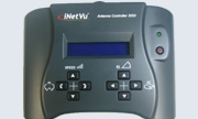
iNetVu® 3000 Hand-Held VSAT Controller The iNetVu® 3000 контроллер для ручного управления антенной позволяет вам свободно управлять двигателями для любого типа антенн iNetVu, без подсоединения компьютера и контроллера. Контроллер 3000 Hand-Held. Спецификация |
 |
|
iNetVu® 7000 VSAT Controller INetVu ® 7000 контроллер идеально подходит для приложений, которым требуется быстрая, простая установка и надежное соединение. Новый контроллер iNetVu ® 7000 имеет высокую точность наведения антенны, его передняя панель имеет удобную клавиатуру для конфигурации и LCD –дисплей, на задней панели имеется разъем для подключения GPS-сигнала для внешних устройств. Контроллер 7000. Спецификация |
 |
|
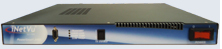
iNetVu® Beacon Receiver INetVu ® BR300L 19 приемник Маяка для монтажа в 19″стойку, блок предназначен для отслеживания уровня плотности мощности спутникового маяка в реальном времени. Он выдает управляющее напряжение, линейно пропорциональное мощности маяка, используя, RMS — детектор мощности. BR300L был специально разработан для работы со всеми типами iNetVu контроллеров ® и платформами VSAT антенн. Ресивер BR300 L. Спецификация |
|
|
iNetVu® PowerSmart 2480 PowerSmart 2480 преобразователь 220/110 В переменного тока в 24/48 постоянного тока был разработан, для обеспечения питанием внешних усилителей ( BUCs), и включает в себя функции поддержки мониторинга и контроля (M & C), функции для нескольких продуктов. Преобразователь PowerSmart 2480. Спецификация |
 |
7000/7024 Controller
HOW TO BUY
Custom Integrations For VSAT Antenna
Page load link
Go to Top