инструкцияGigabyte Z390 Aorus Pro

To reduce the impacts on global warming, the packaging materials of this product
are recyclable and reusable. GIGABYTE works with you to protect the environment.
For more product details, please visit GIGABYTE’s website.
Z390 AORUS
PRO
Z390 AORUS
PRO WIFI
Z390 AORUS PRO
Z390 AORUS PRO
WIFI
User’s Manual
Rev. 1001
12ME-Z39PROW-1001R
Посмотреть инструкция для Gigabyte Z390 Aorus Pro бесплатно. Руководство относится к категории материнские платы, 3 человек(а) дали ему среднюю оценку 9.3. Руководство доступно на следующих языках: английский. У вас есть вопрос о Gigabyte Z390 Aorus Pro или вам нужна помощь? Задайте свой вопрос здесь
- Z390 AORUS PRO (WIFI) Motherboard Layout
- Chapter 1 Hardware Installation
- Chapter 2 BIOS Setup
- Chapter 3 Appendix

Главная
| Gigabyte | |
| Z390 Aorus Pro | Z390 AORUS PRO WIFI | |
| материнская плата | |
| 4719331804299 | |
| английский | |
| Руководство пользователя (PDF), Инструкция по установке (PDF) |
Процессор
| Производитель процессора | Intel |
| Совместимые серии процессоров | Intel Celeron, Intel Core i3, Intel Core i5, Intel Core i7, Intel Pentium |
| Сокет процессора | LGA 1151 (разъем H4) |
Память
| Поддерживаемые типы памяти | DDR4-SDRAM |
| Тип слотов памяти | DIMM |
| Количество слотов памяти | 4 |
| Каналы памяти | Dual-channel |
| Максимальная внутренняя память | 64 GB |
| Небуферизованная память | Да |
| Поддерживаемые объемы модулей памяти | 16GB |
| Поддерживаемые частоты памяти | 2133,2400,2666,2800,3000,3200,3300,3333,3400,3466,3600,3666,3733,3800,3866,4000,4133 MHz |
| без функции коррекции ошибок | Да |
Контроллеры хранения данных
| Поддерживаемые типы накопителей | HDD & SSD |
| Уровни RAID | 0, 1,5, 10 |
Внутренние порты
| Количество параллельных разъемов ATA (PATA) | 0 |
| Разъем питания ATX (24-конт.) | Да |
| EPS разъем питания (8-конт) | Да |
| Разъем вентилятора центрального процессора | Да |
| Количество разъемов вентилятора корпуса | 6 |
| RGB LED контактный разъем | Да |
| Количество разъемов SATA III | 6 |
| Количество разъемов SATA II | 0 |
| Аудиоразъем передней панели | Да |
| Разъем передней панели | Да |
| Разъем выхода S/PDIF | Да |
| Разъемы USB 3.2 Gen 1 (3.1 Gen 1) | 1 |
| Разъемы USB 2.0 | 2 |
| Разъемы USB 3.2 Gen 2 (3.1 Gen 2) | 0 |
| разъемы Thunderbolt | 1 |
| TPM коннектор | Да |
Сеть
| Подключение Ethernet | Да |
| Тип Ethernet интерфейса | Гигабитный Ethernet |
| Wi-Fi | Да |
| Wi-Fi стандартов | 802.11a, Wi-Fi 5 (802.11ac), 802.11b, 802.11g, Wi-Fi 4 (802.11n) |
| Bluetooth | Да |
| Версия Bluetooth | 5.0 |
Свойства
| Семейство чипсета материнской платы | Intel |
| Чипсет материнской платы | Intel Z390 |
| Поддерживаемые операционные системы Windows | Windows 10 |
| Выходные звуковые каналы | 7.1 канала |
| Комплектующие для | ПК |
| Формат материнской платы | ATX |
| Аудио чип | Realtek ALC1220-VB |
BIOS
| Тип BIOS | UEFI AMI |
| Desktop Management Interface (DMI) версия | 2.7 |
| Размер памяти BIOS | 16 Mbit |
| Версия ACPI | 5.0 |
| Версия BIOS (SMBIOS) | 2.7 |
| Перемычка Clear CMOS | Да |
Прочие свойства
Графический адаптер
| Поддержка технологии параллельной обработки | 2-Way CrossFireX, 2-Way SLI, 3-Way CrossFireX, Quad-GPU CrossFireX, Quad-GPU SLI |
Слоты расширения
| PCI Express x1 слоты | 3 |
| PCI Express x16 слоты | 3 |
| Количество M.2 (M) слотов | 2 |
Порты на задней панели
| Количество портов USB 2.0 | 4 |
| Количество портов USB 3.2 Gen 1 (3.1 Gen 1) Type-A | 3 |
| Количество портов USB 3.2 Gen 1 (3.1 Gen 1) Type-С | 0 |
| Количество портов USB 3.2 Gen 2 (3.1 Gen 2) Type-A | 2 |
| Количество портов USB 3.2 Gen 2 (3.1 Gen 2) Type-С | 1 |
| Количество портов Ethernet LAN ( RJ-45) | 1 |
| Количество HDMI портов | 1 |
| Разъем антенны WiFi-AP | 2 |
| Порт выхода S/PDIF | Да |
| Линейные выходы наушников | 1 |
| Линейный вход микрофона | Да |
| Количество портов eSATA | 0 |
| Количество портов PS/2 | 0 |
| Порты FireWire | 0 |
| Количество портов VGA (D-Sub) | 0 |
| Количество портов DVI-D | 0 |
Особые свойства процессора
| Intel® Optane™ Memory Ready | Да |
Вес и размеры
| Ширина | 305 mm |
| Глубина | 244 mm |
Содержимое упаковки
| Поставляемое ПО | Norton® Internet SecurityncFosSpeed |
показать больше
Не можете найти ответ на свой вопрос в руководстве? Вы можете найти ответ на свой вопрос ниже, в разделе часто задаваемых вопросов о Gigabyte Z390 Aorus Pro.
Какая ширина Gigabyte Z390 Aorus Pro?
Какая толщина Gigabyte Z390 Aorus Pro?
Инструкция Gigabyte Z390 Aorus Pro доступно в русский?
Не нашли свой вопрос? Задайте свой вопрос здесь
- Manuals
- Brands
- Gigabyte Manuals
- Computer Hardware
- Z390 I AORUS PRO WIFI
- User manual
-
Contents
-
Table of Contents
-
Bookmarks
Quick Links
Z390 I AORUS PRO WIFI
User’s Manual
Rev. 1001
12ME-Z39ARSI-1001R
For more product details, please visit GIGABYTE’s website.
To reduce the impacts on global warming, the packaging materials of this product
are recyclable and reusable. GIGABYTE works with you to protect the environment.
Related Manuals for Gigabyte Z390 I AORUS PRO WIFI
Summary of Contents for Gigabyte Z390 I AORUS PRO WIFI
-
Page 1
Z390 I AORUS PRO WIFI User’s Manual Rev. 1001 12ME-Z39ARSI-1001R For more product details, please visit GIGABYTE’s website. To reduce the impacts on global warming, the packaging materials of this product are recyclable and reusable. GIGABYTE works with you to protect the environment. -
Page 2
Motherboard Z390 I AORUS PRO WIFI Motherboard Z390 I AORUS PRO WIFI Sept. 13, 2018 Sept. 13, 2018 Wireless Module Country Approvals:… -
Page 3
Information in this manual is protected by copyright laws and is the property of GIGABYTE. Changes to the specifications and features in this manual may be made by GIGABYTE without prior notice. No part of this manual may be reproduced, copied, translated, transmitted, or published in any form or by any means without GIGABYTE’s prior written permission. -
Page 4: Table Of Contents
Table of Contents Z390 I AORUS PRO WIFI Motherboard Layout …………..5 Chapter 1 Hardware Installation ………………6 Installation Precautions ………………6 Product Specifications ………………7 Installing the CPU ………………10 Installing the Memory ………………10 Installing an Expansion Card …………….. 11 Back Panel Connectors ………………
-
Page 5: Z390 I Aorus Pro Wifi Motherboard Layout
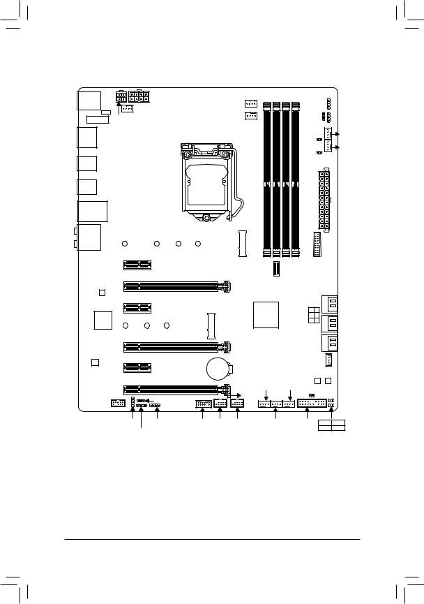
Z390 I AORUS PRO WIFI Motherboard Layout F_USB30C CPU_FAN SYS_FAN2 SYS_FAN1 ATX_12V_2X4 LGA1151 R_USB30 DP_HDMI MegaChips MCDP2800 Intel ® USB30_LAN GbE LAN (Note 1) CNVI D_LED B_BIOS M_BIOS Intel Z390 ® (Note 2) AUDIO ® Super I/O PCIEX16 CODEC Box Contents…
-
Page 6: Chapter 1 Hardware Installation
Chapter 1 Hardware Installation Installation Precautions The motherboard contains numerous delicate electronic circuits and components which can become damaged as a result of electrostatic discharge (ESD). Prior to installation, carefully read the user’s manual and follow these procedures: • Prior to installation, make sure the chassis is suitable for the motherboard. •…
-
Page 7: 1-2 Product Specifications
Support for non-ECC Un-buffered DIMM 1Rx8/2Rx8/1Rx16 memory modules Š Support for Extreme Memory Profile (XMP) memory modules Š (Go to GIGABYTE’s website for the latest supported memory speeds and memory modules.) Onboard Integrated Graphics Processor+MegaChips MCDP2800 chip: Š…
-
Page 8
Chipset: Š 1 x USB Type-C port with USB 3.1 Gen 1 support, available through the ™ internal USB header 1 x USB Type-C port on the back panel, with USB 3.1 Gen 2 support ™ 1 x USB 3.1 Gen 2 Type-A port (red) on the back panel 6 x USB 3.1 Gen 1 ports (4 ports on the back panel, 2 ports available through the internal USB header) 2 x USB 2.0/1.1 ports available through the internal USB header… -
Page 9
System Form Factor Mini-ITX Form Factor; 17.0cm x 17.0cm Š * GIGABYTE reserves the right to make any changes to the product specifications and product-related information without prior notice. Please visit the SupportUtility List Please visit GIGABYTE’s website for support lists of CPU, memory page on GIGABYTE’s website to modules, SSDs, and M.2 devices. -
Page 10: Installing The Cpu
• Make sure that the motherboard supports the memory. It is recommended that memory of the same capacity, brand, speed, and chips be used. (Go to GIGABYTE’s website for the latest supported memory speeds and memory modules.) • Always turn off the computer and unplug the power cord from the power outlet before installing the memory to prevent hardware damage.
-
Page 11: Installing An Expansion Card
The two memory sockets are divided into two channels and each channel has one memory socket as following: Channel A: DDR4_A1 Channel B: DDR4_B1 Due to CPU limitations, read the following guidelines before installing the memory in Dual Channel mode. Dual Channel mode cannot be enabled if only one memory module is installed.
-
Page 12
• When removing the cable, pull it straight out from the connector. Do not rock it side to side to prevent an electrical short inside the cable connector. Please visit GIGABYTE’s website for details on configuring the audio software. — 12 -… -
Page 13: Internal Connectors
Internal Connectors ATX_12V_2X4 F_PANEL SPEAKER CPU_FAN F_USB30C SYS_FAN1/2 F_USB30 D_LED F_USB1 DLED_V_SW LED_C SATA3 0/1/2/3 CLR_CMOS M2P/M2M (Note) F_AUDIO (Note) The M2M connector is on the back of the motherboard. Read the following guidelines before connecting external devices: • First make sure your devices are compliant with the connectors you wish to connect. •…
-
Page 14
1/2) ATX_12V_2X4/ATX (2×4 12V Power Connector and 2×12 Main Power Connector) With the use of the power connector, the power supply can supply enough stable power to all the components on the motherboard. Before connecting the power connector, first make sure the power supply is turned off and all devices are properly installed. -
Page 15
LED strip. For how to turn on/off the lights of the LED strip please visit the «Unique Features» webpage of GIGABYTE’s website. Before installing the devices, be sure to turn off the devices and your computer. Unplug the power cord from the power outlet to prevent damage to the devices. -
Page 16: Chipset
DEBUG PORT F_USB3 F
 SATA3 0/1/2/3 (SATA 6Gb/s Connectors) The SATA connectors conform to SATA 6Gb/s standard and are compatible with SATA 3Gb/s and SATA 1.5Gb/s standard. Each SATA connector supports a single SATA device. The Intel Chipset supports RAID 0, ®…
 -
Page 17
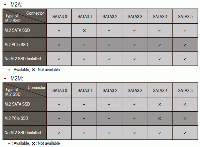
Installation Notices for the M.2 and SATA Connectors: Due to the limited number of lanes provided by the Chipset, the availability of the SATA connectors may be affected by the type of device installed in the M.2 connector. The M2P connector shares bandwidth with the SATA3 1 connector. -
Page 18: Power
11) F_PANEL (Front Panel Header) Connect the power switch, reset switch, and system status indicator on the chassis to this header according to the pin assignments below. Note the positive and negative pins before connecting the cables. RES+ Power Switch Reset Switch RES- PLED-…
-
Page 19
13) F_USB30C (USB Type-C Header with USB 3.1 Gen 1 Support) ™ The header conforms to USB 3.1 Gen 1 specification and can provide one USB port. F_USB3 F_USB30 3 Pin No. Definition Pin No. Definition Pin No. Definition VBUS RX2+ TX1+ SBU1… -
Page 20
16) TPM (Trusted Platform Module Header) You may connect a TPM (Trusted Platform Module) to this header. Pin No. Definition Pin No. Definition LAD0 LAD3 VCC3 LAD1 LFRAME No Pin LAD2 SERIRQ LCLK LRESET 17) CI (Chassis Intrusion Header) This motherboard provides a chassis detection feature that detects if the chassis cover has been removed. This function requires a chassis with chassis intrusion detection design.
 SATA3 0/1/2/3 (SATA 6Gb/s Connectors) The SATA connectors conform to SATA 6Gb/s standard and are compatible with SATA 3Gb/s and SATA 1.5Gb/s standard. Each SATA connector supports a single SATA device. The Intel Chipset supports RAID 0, ®…
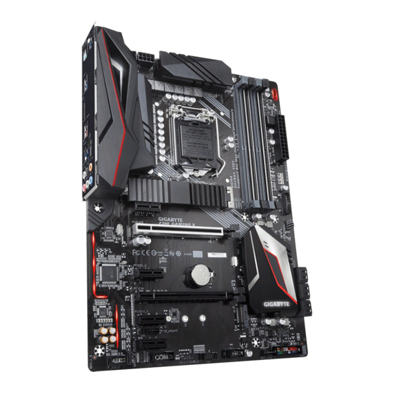
 Материнская плата Gigabyte Z390 Aorus Pro на новом наборе системной логики Intel Z390 относится к среднему классу, расположившись между старшими Xtreme, Master и Ultra, а также младшей Elite. Тем не менее, в сравнении со своей предшественницей на чипсете Intel Z370 — платой Z370 Aorus Ultra Gaming — изменения в ней более чем заметны и затронули практически каждый компонент на текстолите, за исключением, пожалуй, сетевого контроллера. Подогревает интерес к этому факту и то, что сам набор системной логики Intel Z370 отличается от Z390 в минимальной степени. Тогда вполне резонно возникает вопрос: за счет чего инженеры Gigabyte внесли в плату столько изменений и что именно Z390 Aorus Pro готова предложить поклонникам серии? Ответы на эти и другие вопросы вы найдете в статье.
Технические характеристики
| Процессорный разъем | LGA1151-v2 |
|---|---|
| Чипсет | Intel Z390 |
| Память | 4 × DDR4, до 64 ГБ, до DDR4-4266 МГц |
| Аудиоподсистема | Realtek ALC1220-VB + конденсаторы Wima FKP2 и Nichicon |
| Сетевые контроллеры | Intel Ethernet Connection i219-V (10/100/1000 Мбит/с, поддержка cFosSpeed) |
| Слоты расширения | 1 × PCI Express 3.0 x16 1 × PCI Express 3.0 x8 1 × PCI Express 3.0 x4 3 × PCI Express 3.0 x1 |
| Разъемы для накопителей | 6 × SATA 6 Гбит/с 2 × M.2 (для 1 накопителя форматов 2242/2260/2280/22110 и 1 накопителя форматов 2242/2260/2280) |
| USB-порты | 3 × USB 3.1 Gen2 (3 порта на задней панели) 6 × USB 3.1 Gen1 (3 порта на задней панели) 8 × USB 2.0 (4 порта на задней панели) |
| Разъемы на задней панели | 4 × USB 2.0 1 × HDMI 3 × USB 3.1 Gen1 3 × USB 3.1 Gen2 1 × RJ-45 5 аудиоразъемов типа миниджек 1 × S/PDIF (оптический, выход) |
| Прочие внутренние разъемы | 24-контактный разъем питания ATX 8-контактный разъем питания EPS12V 4-контактный разъем питания ATX12V 1 разъем для подключения жидкостной системы охлаждения ЦП 4 разъема для подключения корпусных вентиляторов 2 разъема для вентилятора системы/помпы СЖО 2 разъема для подключения неадресуемых RGB-лент 2 разъема для подключения адресуемых RGB-лент 6 разъемов SATA 6 Гбит/с 2 разъема M.2 Socket 3 2 разъема для подключения внешних термодатчиков 1 разъем для подключения порта USB 3.1 Gen1 Type-C 1 разъем для подключения 2 портов USB 3.1 Gen1 2 разъема для подключения 4 портов USB 2.0 группа разъемов для кнопок и индикаторов передней панели корпуса группа аудиоразъемов для передней панели корпуса 1 разъем Thunderbolt1 1 разъем TPM-модуля 1 перемычка для очистки CMOS |
| Форм-фактор | ATX (305 × 244 мм) |
| Средняя цена |
узнать цены |
| Розничные предложения |
узнать цену |
Упаковка и комплектация
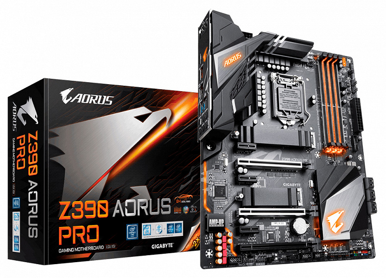
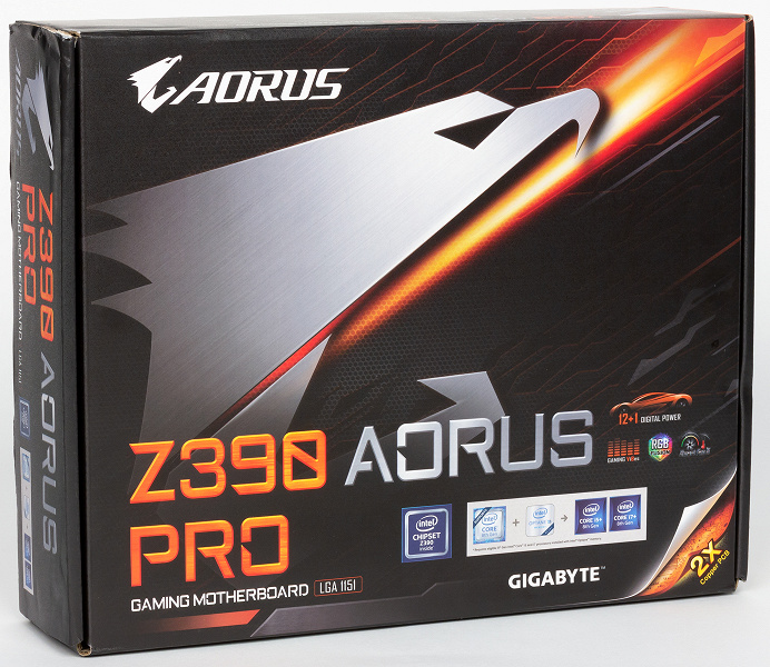
Оформление упаковки Gigabyte Z390 Aorus Pro не претерпело дизайнерских изменений в сравнении с коробками плат предыдущего цикла. На ее лицевой стороне по-прежнему схематично изображен взмывающий ввысь сокол, а снизу указаны модель платы, поддерживаемые процессоры и ключевые особенности.
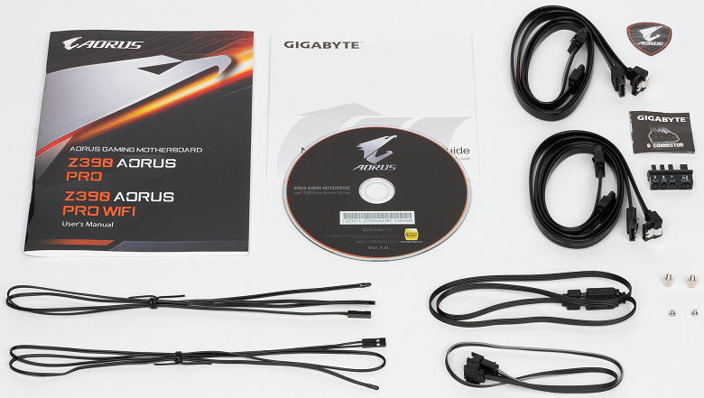
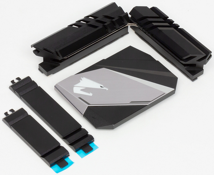
В комплект поставки Gigabyte Z390 Aorus Pro входят инструкция по эксплуатации, два кабеля с термодатчиками, DVD с драйверами и утилитами, четыре SATA-кабеля с защелками, наклейка Aorus, колодка для удобного подключения кабелей передней панели корпуса, два кабеля для лент RGB-подсветки и винты для крепления накопителей в портах M.2.
Плата производится на Тайване и обеспечивается трехлетней гарантией. В России Gigabyte Z390 Aorus Pro уже продается и стоит около 14 тысяч рублей — это средний ценовой уровень для платформ на наборе системной логики Intel Z390. Добавим, что в ассортименте Gigabyte есть точно такая же плата, но со встроенным беспроводным контроллером Wi-Fi, стоимость которой примерно на 700 рублей выше.
Дизайн и особенности
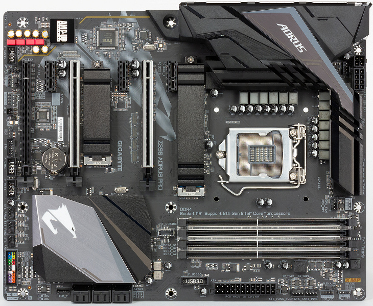
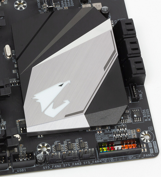
В плане дизайна плата выделяется массивными радиаторами на силовых цепях, частично накрытыми кожухом, и плоским радиатором чипсета довольно большой площади.

Также обращают на себя внимание яркие конденсаторы аудиокодека и ребристые по краям радиаторы накопителей в портах M.2.
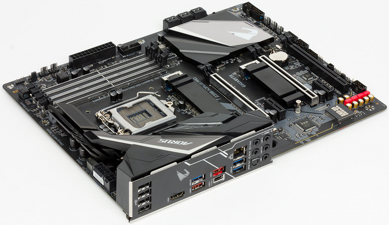
Размеры платы составляют 305×244 мм, то есть она имеет форм-фактор ATX.
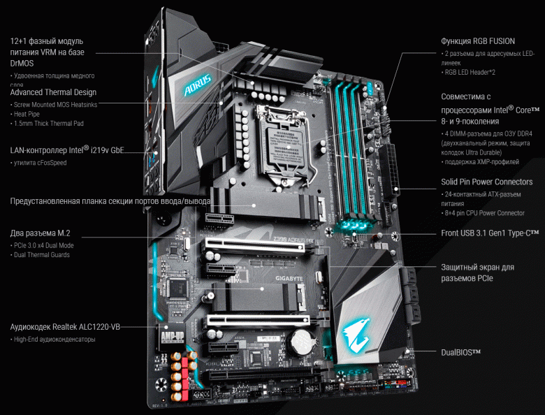
Большинство достоинств новой Gigabyte Z390 Aorus Pro приведены на картинке ниже. Среди них отметим усиленную систему питания процессора с переработанным охлаждением, дополнительно оптимизированный аудиокодек, металлизированные оболочки двух слотов PCI Express, двойной BIOS и равномерно распределенную по текстолиту подсветку.
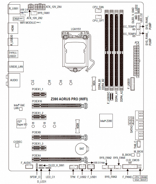
Детально со всеми элементами и контроллерами платы можно ознакомиться по схеме из инструкции по эксплуатации.
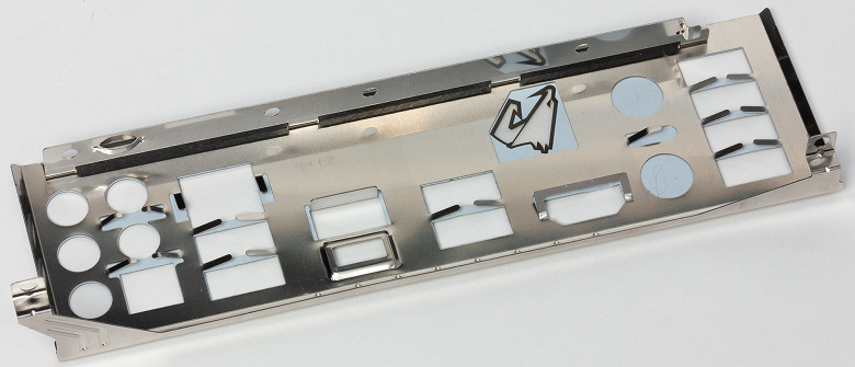
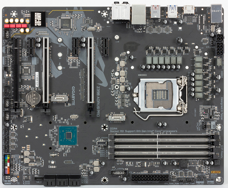
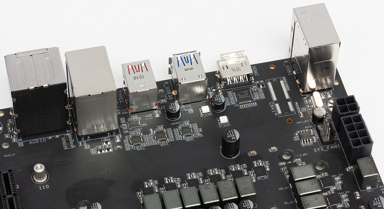
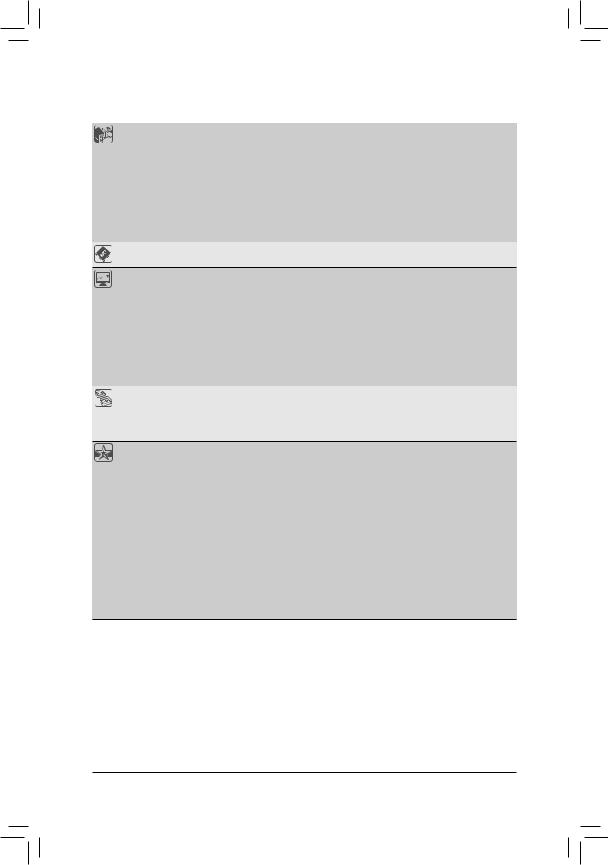
Интерфейсная панель Gigabyte Z390 Aorus Pro содержит сразу десять портов USB, HDMI-выход, сетевую розетку RJ-45 и шесть аудиовыходов, включая S/PDIF.
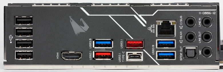
Здесь нужно отметить два момента. Во-первых, все порты подписаны, что очень удобно при подключении. Во-вторых, встроенную интерфейсную панель портов. Впрочем, последнюю при необходимости всегда можно снять, поскольку крепление у нее винтовое, а не клеевое.
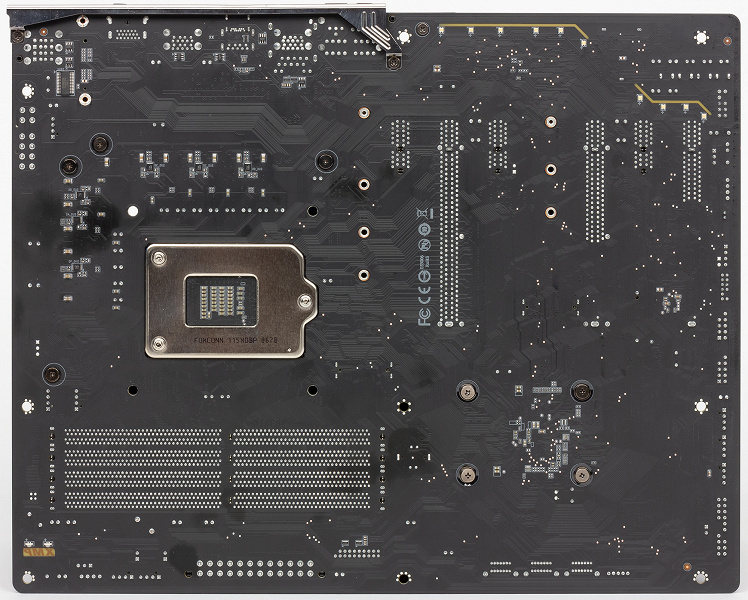
Набор системной логики Intel Z390, прямо сказать, не изобилует функциональностью, поэтому все элементы платы расположены на ее лицевой стороне.
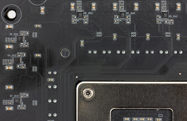
На обратную вынесены только дублеры элементов силовой цепи питания процессора и пара мелких микросхем.
Традиционно отметим высокое качество сборки Gigabyte Z390 Aorus Pro, здесь вы не найдете криво распаянных элементов или излишков припоя некачественной пайки. Все выполнено очень аккуратно и точно. Кроме того, текстолит платы содержит медные слои удвоенной толщины, что позволяет повысить стабильность и удерживать более низкую температуру при высоких нагрузках.
Крепления всех навесных элементов к текстолиту винтовое, поэтому не придется возиться со снятием неудобных пластиковых клипс-гвоздей, а также беспокоиться о недостаточном прижиме радиаторов к охлаждаемым ими элементам.
Поскольку процессорный разъем LGA1151-v2 здесь не имеет какой-то оптимизации или фирменных особенностей, поддерживая все выпускаемые в данном конструктивном исполнении процессоры, то сразу посмотрим на силовые цепи.
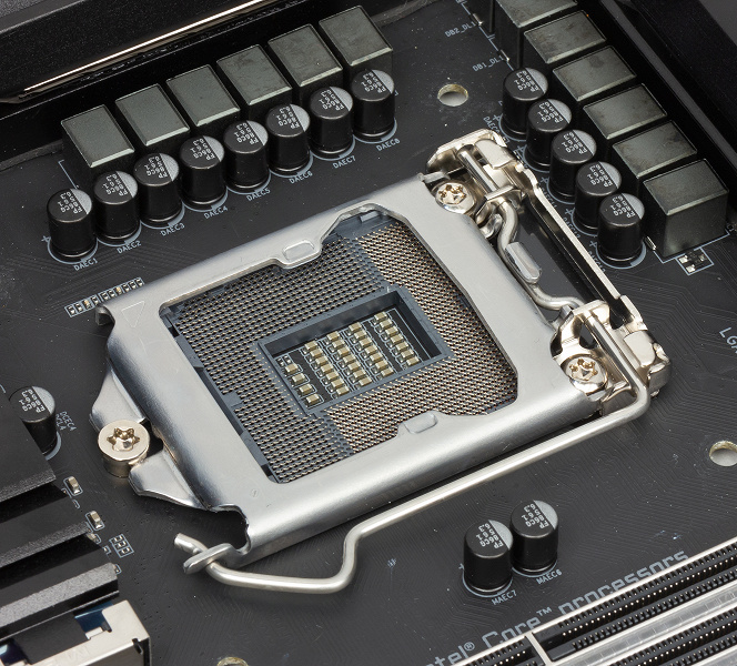
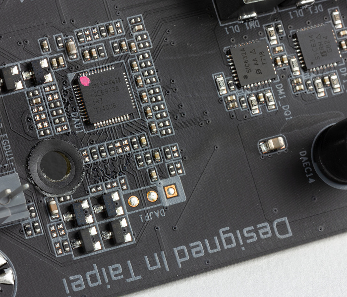
На официальной странице платы заявлено применение системы питания процессора с использованием сборок DrMOS по схеме «12+1» на транзисторах Vishay Siliconix SiC634 (50А) с дублерами ISL6617A с обратной стороны платы.
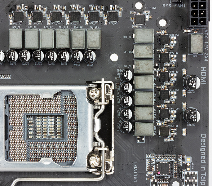
Еще одним элементом цепи питания является силовой транзистор SiC620A (60A), отвечающий за встроенное в процессор графическое ядро. За управление питанием процессора отвечает семиканальный PWM-контроллер Intersil ISL69138.
Два стандартных разъема питания с 24 и 8 контактами на Gigabyte дополнены еще одним четырехконтактным. Подключение к нему кабеля не обязательно.
Кстати, все контактные иглы внутри разъемов цельнометаллические, а не полые внутри.
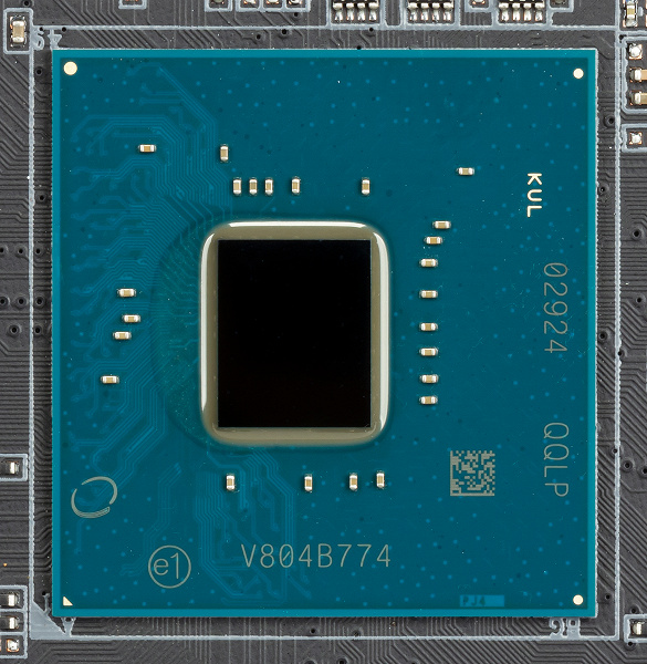
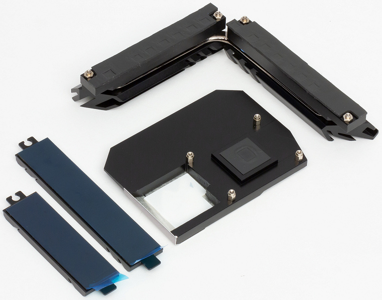
Кристалл чипсета Intel Z390 контактирует с радиатором через термопрокладку, поэтому отчищать его от термоклея или термопасты на Gigabyte Z390 Aorus Pro не требуется.
Несмотря на тот факт, что Z390 Aorus Pro не относится к флагманским моделям Gigabyte на этом наборе системной логики, все ее слоты DIMM оперативной памяти получили металлизированную оболочку Ultra Durable Memory Armor, которая не только усиливает сами разъемы, но и защищает контакты в них от электромагнитных помех.
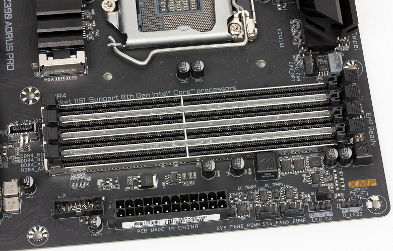
Платой поддерживаются DDR4-модули суммарным объемом 64 ГБ с частотами от 2133 до 4266 МГц и XMP (Extreme Memory Profile), а с перечнем сертифицированных для данной модели платы комплектов памяти можно ознакомиться на официальном сайте.
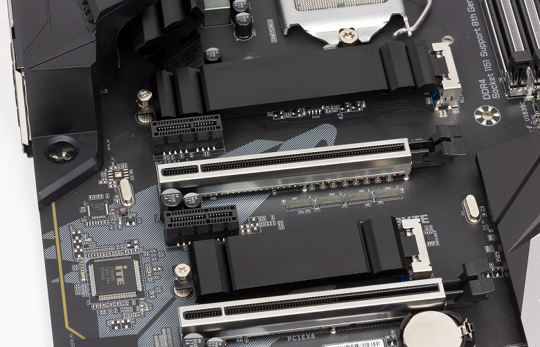
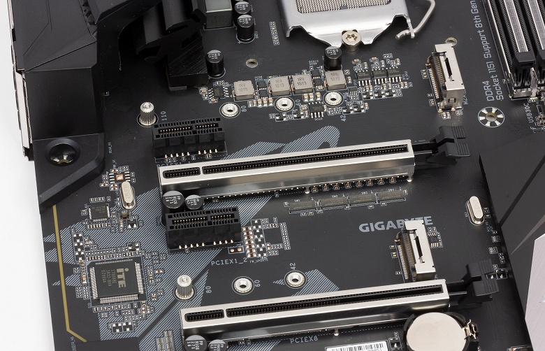
Gigabyte Z390 Aorus Pro оснащена шестью слотами PCI Express, три из которых выполнены в конструктивном исполнении x16 и два из них имеют дополнительную металлическую оболочку, усиливающую слоты на излом в 1,7 раза и в 3,2 раза на выдергивание.
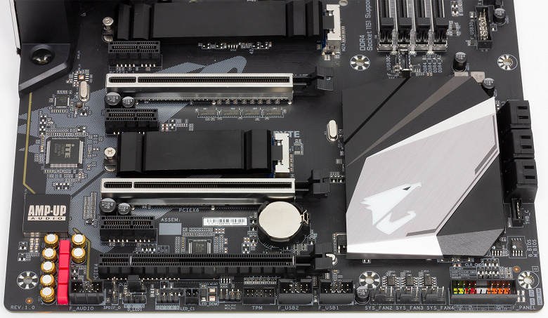
При этом только один «металлизированный» слот является полноценным 3.0 x16, подключен к процессору и может работать с видеокартами на максимальной пропускной способности 15,8 ГБ/с. Второй такой слот способен работать только в режиме x8, что позволит объединить в них две видеокарты Nvidia в 2-way SLI или в две AMD в 2-way CrossFireX. Теоретически на этой плате будут работать и три видеокарты, но только если они базируются на графических процессорах AMD и их объединение будет реализовано по схеме х8/х8/х4.
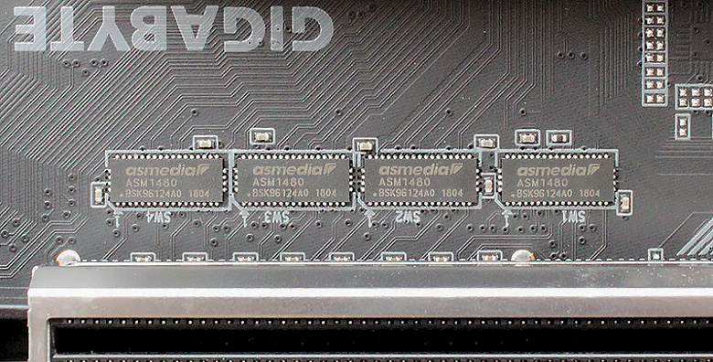
За коммутацию линий PCI Express на Gigabyte Z390 Aorus Pro отвечают четыре микросхемы-мультиплексора ASM1480 производства ASMedia.
Остальные 4 слота PCI Express могут работать только в режиме x1 и предназначены для различных карт расширения.
Все шесть портов SATA600 с пропускной способностью до 6 Гбит/с на плате реализованы возможностями чипсета и расположены в горизонтальной ориентации.
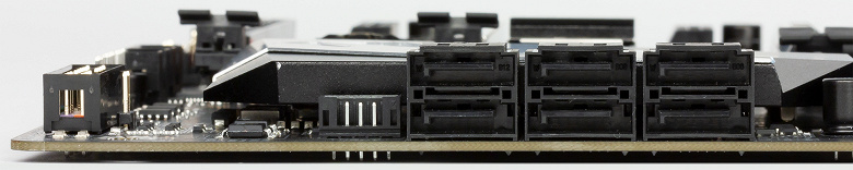
Ими поддерживается создание массивов RAID уровней 0, 1, 5 и 10, а также различных технологий хранения данных Intel.
Для высокоскоростных накопителей SSD на плате есть два порта M.2 с пропускной способностью до 32 Гбит/с.
Оба порта поддерживают как SATA-, так и PCIe-накопители, но в верхний можно установить модули длиной от 42 до 110 мм, а в нижний — длиной от 42 до 80 мм. Отметим, что для накопителей в обоих портах предусмотрены массивные радиаторы, что ранее было редкостью для плат данного ценового сегмента. Ограничения по одновременному использованию подключенных к плате накопителей приведены в таблице.
Недостатка в USB-портах у Gigabyte Z390 Aorus Pro нет. Их общее число равно 17, из которых 10 выведены на заднюю панель, а 7 размещены непосредственно на текстолите. В числе последних есть и порт USB 3.1 Gen1 Type-C для передней панели корпуса системного блока.

Беспроводной сети на плате нет, а проводная реализована проверенным временем контроллером Intel i219-V.
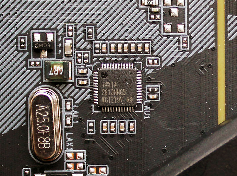
Данный контроллер поддерживает технологию приоритезации трафика cFosSpeed, способствующую уменьшению задержек и снижению времени отклика.
В основе звукового тракта платы лежит 7.1-канальный HDA-аудиокодек Realtek ALC1220-VB, экранированный металлическим колпачком.
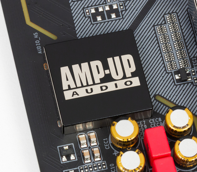
Отсутствие встроенного усилителя в аппаратной части звукового тракта разработчики попытались компенсировать семью «аудиофильскими» конденсаторами Nichicon японского производства и четырьмя Hi-Fi-конденсаторами Wima FKP2.
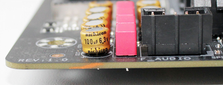
Не забыта на плате и изоляция аудиозоны парой токонепроводящих полосок.
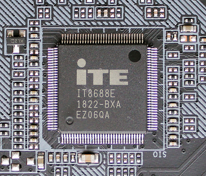
За функции Super I/O и мониторинга на Gigabyte Z390 Aorus Pro отвечает контроллер iTE IT8688E.
К плате можно подключить сразу восемь вентиляторов с ШИМ-управлением, причем два из них имеют повышенную до 2 А силу тока для обслуживания энергоемких помп систем жидкостного охлаждения.

Кроме того, плата имеет восемь встроенных термодатчиков и два коннектора для подключения внешних термодатчиков. На наш взгляд, это попросту отменное оснащение для мониторинга. При этом на плате нет индикатора POST-кодов, его частично заменяют четыре светодиода в верхнем правом углу текстолита, но это, прямо говоря, слабое утешение.
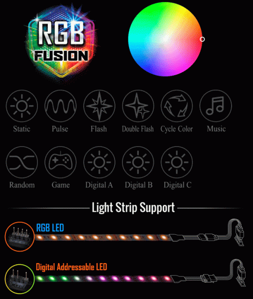
Контроллер iTE 8295E на Gigabyte Z390 Aorus Pro отвечает за работу подсветки RGB Fusion.

На самой плате подсвечивается зона радиатора чипсета, логотип Aorus на кожухе радиаторов VRM, две полоски экранирования зоны аудио, а также слоты оперативной памяти.

Кроме встроенной подсветки, к плате можно подключить две адресуемые и две не адресуемые светодиодные ленты, длина каждой из которых может достигать двух метров. Управление подсветкой и синхронизация подсветки RGB-лент осуществляется через фирменное приложение Gigabyte RGB Fusion.
Gigabyte Z390 Aorus Pro имеет две 128-мегабитные микросхемы BIOS: основную и резервную.

В случае повреждения микрокода основной микросхемы BIOS, восстановление из резервной осуществляется в автоматическом режиме. Эмпирически мы выяснили, что, чтобы загрузиться с резервной микросхемы, нужно задержать клавишу включения на три-четыре секунды.
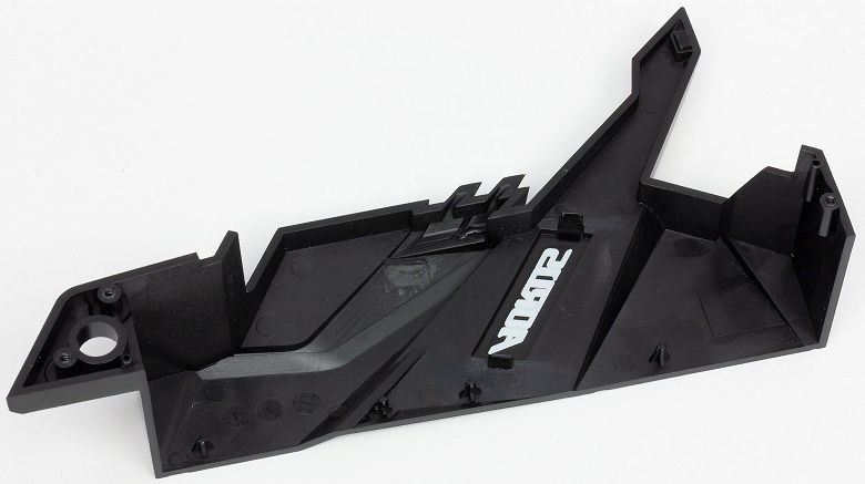
Пластиковый кожух закрепляется на плате тремя винтами и выполняет исключительно декоративную функцию.
Винтовое крепление имеют и все радиаторы Gigabyte Z390 Aorus Pro.
Они выполнены из алюминия и имеют термопрокладки, а пара радиаторов на VRM-цепях соединена друг с другом 6-миллиметровой тепловой трубкой.
Возможности UEFI BIOS
Во время тестирования нами Gigabyte Z390 Aorus Pro последний доступный BIOS F7a был в бета-статусе и датирован 7 ноября 2018 года. Он и был прошит в основную микросхему на плате. В этом разделе мы сразу же приведем скриншоты BIOS с настройками процессора и памяти, которых нам удалось достичь при разгоне в процессе тестирования и о которых мы расскажем уже в следующем разделе.
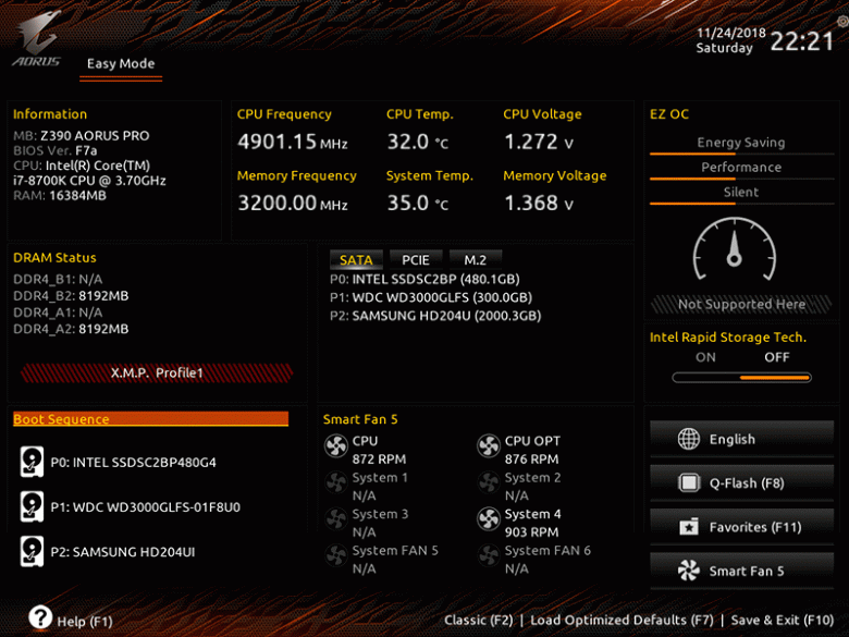
Сначала загружается упрощенный режим EZ Mode, который в большей степени является информационным, нежели функциональным. Здесь можно выбрать загрузочный накопитель, отрегулировать скорость вентиляторов и активировать один из запрограммированных в BIOS режимов работы платформы: энергосберегающий, повышенной производительности или тихий.
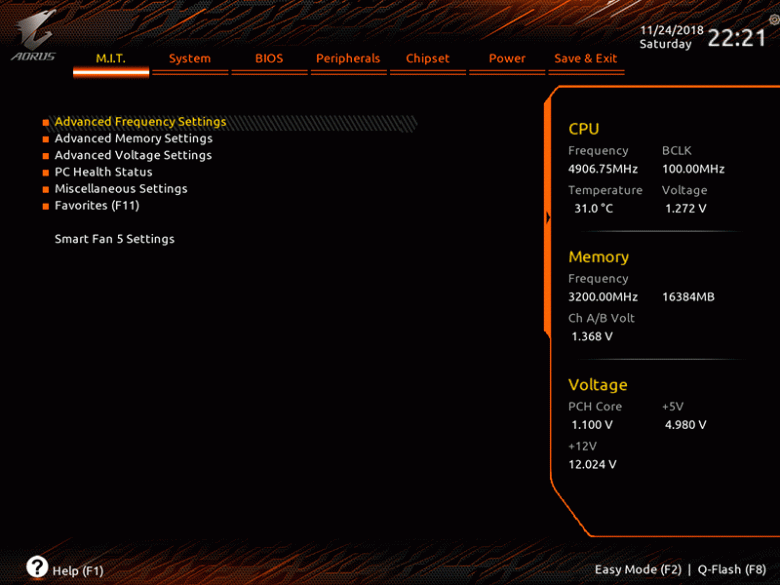
Переключение в классический режим BIOS происходит при нажатии на F2 и здесь уже доступны семь основных разделов с вложенными в них подразделами. Сразу же обращает на себя внимание несколько иное цветовое оформление оболочки, чем в платах Gigabyte Aorus предыдущей серии. Дополнительно появилось большее количество подсказок, а звездочками помечены пункты, добавляемые в подраздел «Избранное» (или наиболее часто используемые).
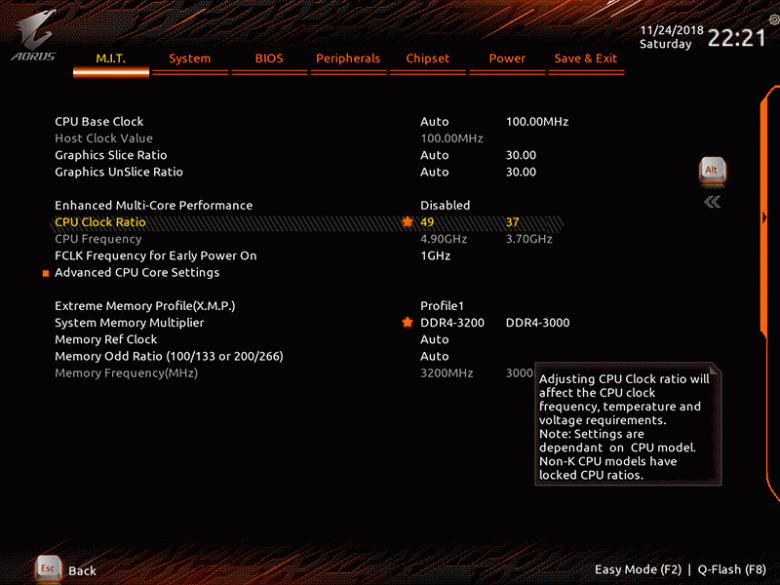
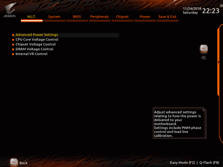
Сначала пользователь сразу же попадает в основной раздел M.I.T. (MB Intelligent Tweaker), где собраны шесть подразделов с возможностями разгона процессора и оперативной памяти, а также встроенная утилита Smart Fan 5.
Первый подраздел относится к базовым настройкам частоты и множителя процессора, а также основным параметрам работы оперативной памяти.
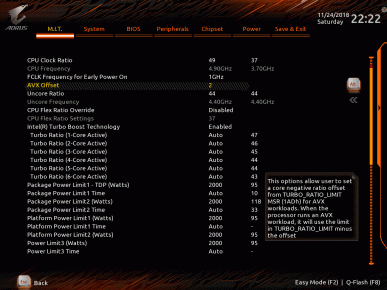
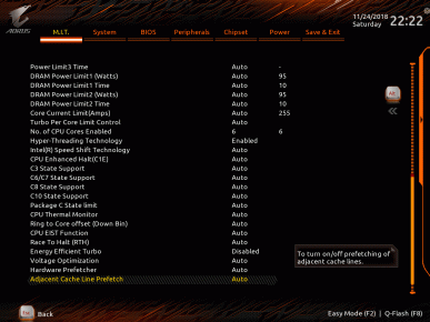
Проваливаясь глубже в подраздел дополнительных настроек процессора, можно увидеть огромное количество доступных к изменению параметров, включая занижение множителя при выполнении AVX-инструкций и настройку множителя для каждого ядра процессора, что будет полезно при изучении предела его оверклокерских возможностей.
Для модулей оперативной памяти предусмотрен неограниченный выбор частот.
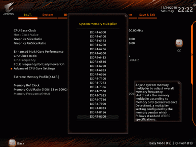
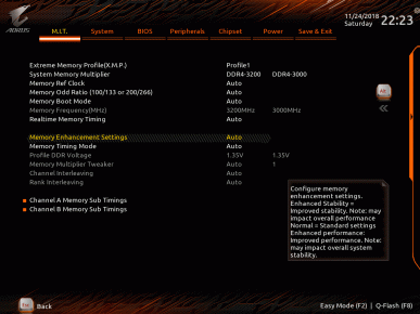
Кроме того, здесь же доступны шесть профилей работы памяти от стандартного до высокочастотного.
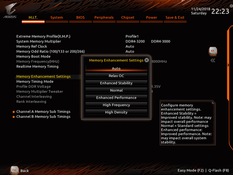
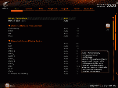
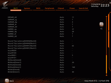
Для прожигателей времени не забыта и возможность ручной настройки таймингов памяти.
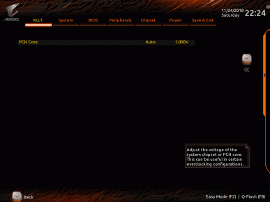
Следом за ним идет подраздел с параметрами регулировки напряжений и режимами их стабилизации.
Для процессора здесь предусмотрены сразу же восемь уровней стабилизации напряжения (LLC). Удобно, что при выборе каждого из них, на простеньком графике показывается, в какой степени напряжение будет стабилизировано.
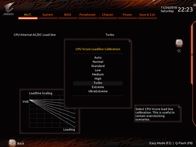
Забегая вперед, можно добавить, что в процессе тестирования мы выяснили, что уровень стабилизации Turbo точнее остальных держит заданное напряжение на ядре, тогда как уровни Extreme и UltraExtreme его завышают. Кстати, кроме процессорного, ручной регулировке в BIOS платы доступно огромное количество других напряжений.
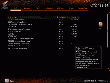
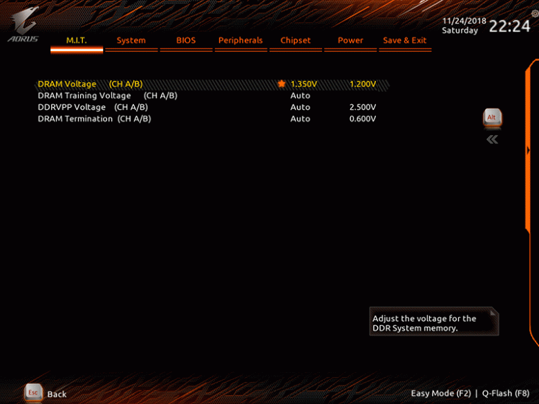
Перечислим основные из них с границами изменений и шагом.
| Напряжение | Минимальное значение, В | Максимальное значение, В | Шаг |
|---|---|---|---|
| CPU VCore | 1,100 | 1,800 | 0,005 |
| CPU GTCore | 0,500 | 1,500 | 0,005 |
| CPU VCCIO | 0,800 | 1,500 | 0,010 |
| CPU System Agent | 0,800 | 1,500 | 0,010 |
| VСС Substained | 0,800 | 1,500 | 0,010 |
| VСС PLL | 0,800 | 1,500 | 0,010 |
| VCC PLL OC | 0,800 | 3,010 | 0,010 |
| PCH Core | 0,800 | 1,300 | 0,020 |
| DRAM | 1,000 | 2,000 | 0,010 |
| DRAM VPP | 1,980 | 3,020 | 0,040 |
| DRAM Termination | 0,506 | 1,125 | 0,005/0,006 |
Вместе с этим к изменению доступен ряд второстепенных напряжений, а также масса параметров, относящихся к лимитам питания.
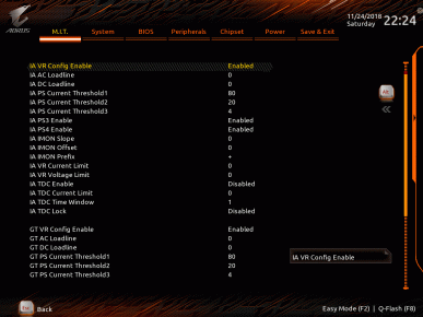
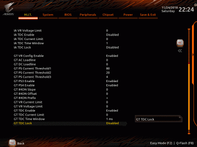
Здесь же расположен подраздел с мониторингом всех напряжений в реальном времени.

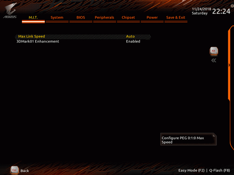
В предпоследнем подразделе основного раздела M.I.T. находятся два параметра: выбор режима работы главного порта PCI Express и активация оптимизаций для старых бенчмарков.
Встроенная в BIOS утилита для мониторинга параметров системы и управления скоростью вентиляторов Smart Fan 5 и ранее считалась одной из лучших среди себе подобных, но теперь она стала еще более функциональной и удобной.
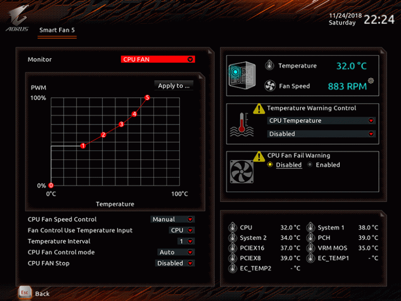
В ней можно настроить каждый подключенный к плате вентилятор индивидуально, либо все сразу в ручном режиме в зависимости от определенного датчика платы по алгоритму ШИМ-управления или изменением напряжения. Также здесь можно установить температурные границы, а все изменения применяются сразу же при их юстировке.
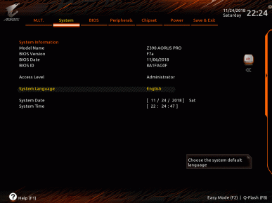
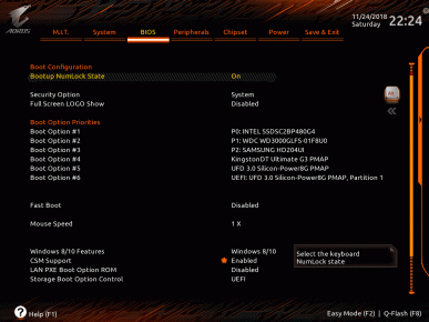
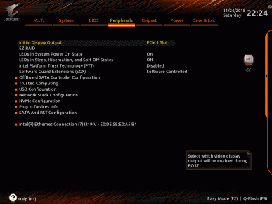
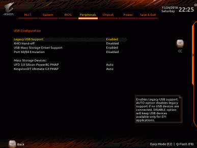
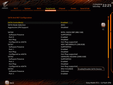
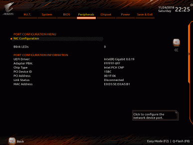
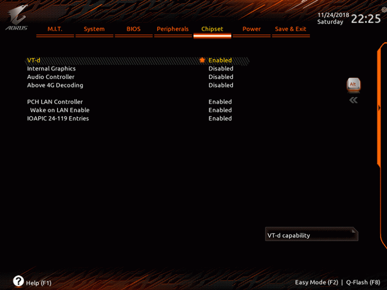
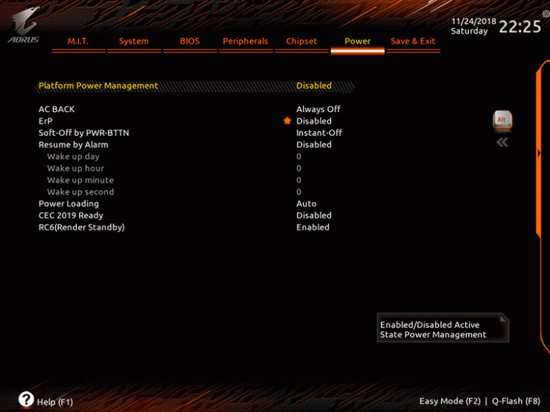
Остальные разделы BIOS материнской платы менее интересны и, на наш взгляд, не требуют комментариев, поэтому далее мы просто приведем их скриншоты.
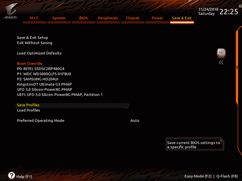
Добавим, что в BIOS платы есть встроенная утилита Q-Flash, с помощью которой очень просто можно обновить микрокод материнской платы.
Сама оболочка работает очень шустро, а ее старт на Gigabyte Z390 Aorus Pro и вовсе можно назвать мгновенным. При выходе из BIOS отображаются все измененные настройки, чтобы их можно было еще раз перепроверить.
Разгон и стабильность
Проверка стабильности, оверклокерского потенциала и производительности материнской платы Gigabyte Z390 Aorus Pro была проведена в закрытом корпусе системного блока при температуре в помещении около 25 градусов Цельсия. Конфигурация тестового стенда состояла из следующих комплектующих:
- системная плата: Gigabyte Z390 Aorus Pro (Intel Z390, LGA1151-v2, BIOS F7а от 7.11.2018);
- процессор: Intel Core i7-8700K 3,7/4,7 ГГц (Coffee Lake, 14++ нм, U0, 6 × 256 КБ L2, 12 МБ L3, TDP 95 Вт);
- система охлаждения CPU: Noctua NH-D15 (два вентилятора Noctua NF-A15 140 мм на 740—1530 об/мин);
- термоинтерфейс: Arctic MX-4;
- видеокарта: Nvidia GeForce RTX 2080 Founder’s Edition 8 ГБ/256 бит, 1515—1800(1965)/14000 МГц;
- оперативная память: 2 × 8 ГБ DDR4 GeIL Super Luce RGB (GLS416GB3000C16ADC), XMP 3000 МГц 16-18-18-36 CR2 при 1,35 В;
- системный диск: Intel SSD 730 480 ГБ (SATA600, BIOS vL2010400);
- диск для программ и игр: Western Digital VelociRaptor 300 ГБ (SATA300, 10 000 об/мин, 16 МБ, NCQ);
- архивный диск: Samsung Ecogreen F4 HD204UI 2 ТБ (SATA300, 5400 об/мин, 32 МБ, NCQ);
- звуковая карта: Auzen X-Fi HomeTheater HD;
- корпус: Thermaltake Core X71 (6 × be quiet! Silent Wings 2 [BL063] на 900 об/мин: 3 — на вдув, 3 — на выдув);
- панель управления и мониторинга: Zalman ZM-MFC3;
- блок питания: Corsair AX1500i Digital ATX (1500 Вт, 80 Plus Titanium), вентилятор 140 мм.
Тестирование было проведено под управлением операционной системы Microsoft Windows 10 Pro (1803 17134.441) с установкой следующих драйверов:
- чипсет материнской платы Intel Chipset Drivers — 10.1.17833.8098 WHQL от 08.11.2018;
- Intel Management Engine Interface (MEI) — 12.0.1165 WHQL от 14.11.2018;
- драйверы видеокарты — Nvidia GeForce 416.94 WHQL от 14.11.2018.
Стабильность системы при разгоне мы проверяли стресс-утилитой Prime95 29.4 build 8 и другими бенчмарками, а мониторинг проводился с помощью HWiNFO64 версии 5.92-3580.
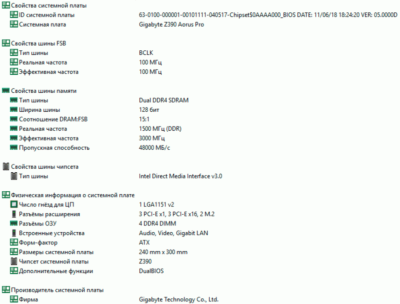
Характеристики платы Gigabyte Z390 Aorus Pro мы приведем из утилиты AIDA64 Extreme.
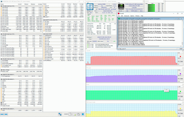
Первый тест Prime95 на собранной конфигурации мы проводили при автоматических настройках BIOS, за исключением активации профиля XMP оперативной памяти.

Никаких неприятных сюрпризов плата Gigabyte Z390 Aorus Pro не преподнесла, обеспечив стабильную работу процессора на частотах от 3700 до 4500 МГц при напряжении от 0,696 до 1,260 В.
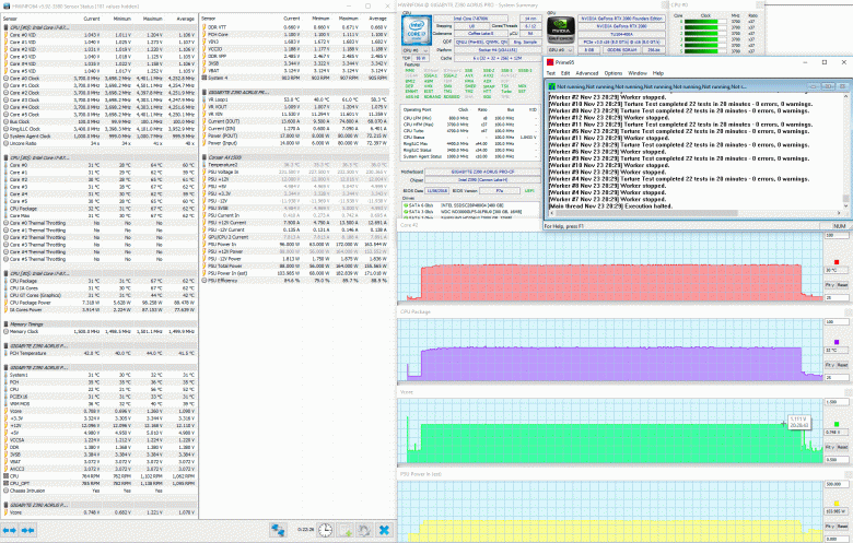
Температура наиболее горячего ядра процессора не превысила отметку 67 градусов Цельсия, а энергопотребление системы в целом ограничилось 183 ваттами. Отметим, что без нагрузки энергопотребление оказалось ниже 70 ватт. То есть автоматические настройки BIOS платы вполне хорошо подходят для повседневного использования системы в таком режиме, не перегревают процессор, как это бывало на платах предыдущего поколения (когда приходилось подбирать напряжение и LLC вручную), и удерживают платформу в достаточно сбалансированном с точки зрения энергопотребления состоянии. Теперь перейдем к разгону.
Попытки разгона процессора мы начали с довольно скромной частоты 4,8 ГГц с последующим подбором уровня LLC и напряжения. По ходу тестирования удалось выяснить, что уровень Turbo точнее семи других стабилизирует напряжение, которое потребовалось зафиксировать на 1,185 В.

С таким разгоном процессора плата справилась довольно легко, а его температуры не превысили 77 градусов Цельсия.
Энергопотребление системы в нагрузке в сравнении с автоматическими настройками BIOS платы возросло со 183 до 239 Вт, а в режиме простоя практически не изменилось.
Следующей ступенькой разгона нашего экземпляра процессора Intel Core i7-8700K стали 4,9 ГГц, для достижения которых при том же уровне стабилизации пришлось повысить напряжение до 1,255 В.
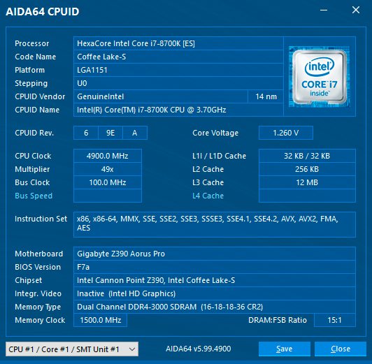
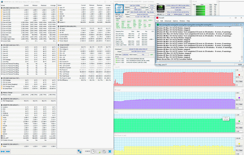
Пиковая температура процессора выросла примерно на 10 градусов Цельсия, но все еще оставалась во вполне допустимых пределах. А вот с дальнейшей ступенькой разгона процессора — 5,0 ГГц — плата уже не справилась, поскольку температура процессора в процессе тестирования едва переходила отметку 95 градусов Цельсия и далее стабильности не удавалось достичь даже при дальнейшем повышении напряжения. Ранее на платах с чипсетом Intel Z370 (в том числе на Gigabyte Z370 Aorus Gaming 7) в сопоставимых условиях нам удавалось добиться стабильности от этого же экземпляра процессора на частоте 5,0 ГГц при максимальных температурах около 100 градусов Цельсия. Но здесь влияние могли оказывать как все же несколько иные условия, так и иной алгоритм стабилизации напряжения на ядре процессора.
Тем не менее, полученный на Gigabyte Z390 Aorus Pro результат разгона процессора — вполне достойный, тем более, что разница в производительности от дополнительных 0,1 ГГц мизерна. Это нам косвенно подтвердит и блиц-тестирование производительности в следующем разделе статьи.
Производительность
Производительность системы, собранной на Gigabyte Z390 Aorus Pro, мы проверили в двух режимах: при автоматических настройках BIOS с активированным XMP оперативной памяти, а также при разгоне процессора до 4,9 ГГц и повышении частоты памяти до 3,2 ГГц. Результаты девяти разнообразных тестов позволят оценить прирост производительности от разгона платформы, который, как оказалось, не такой уж и впечатляющий.
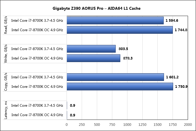
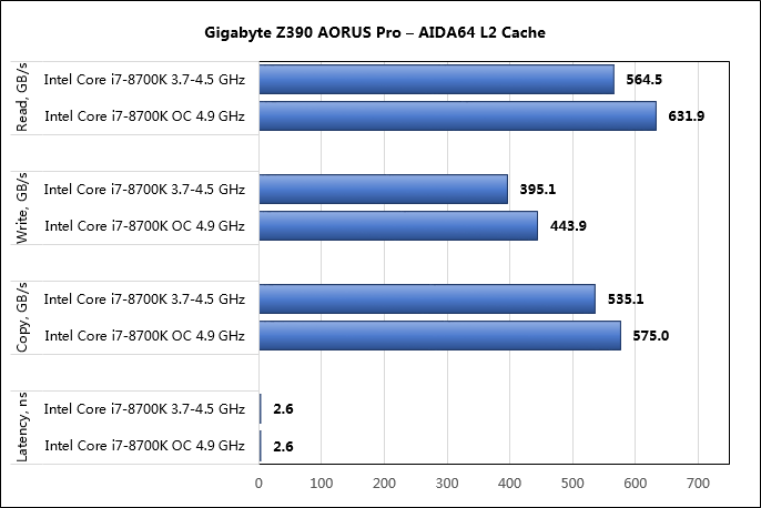

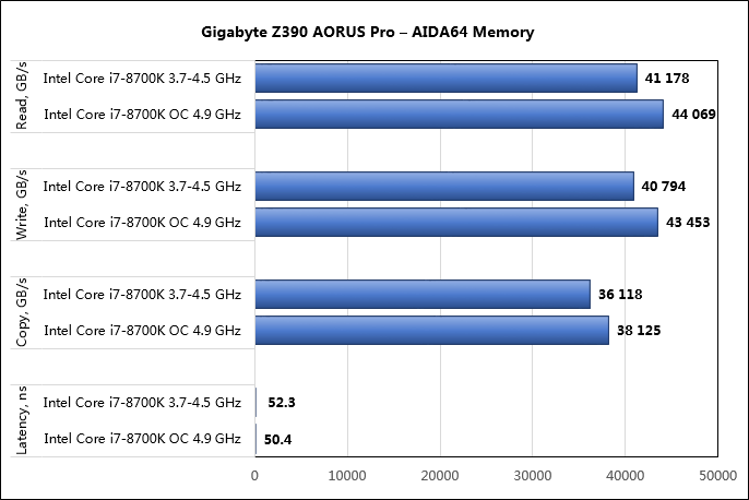


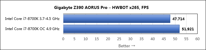
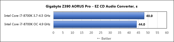
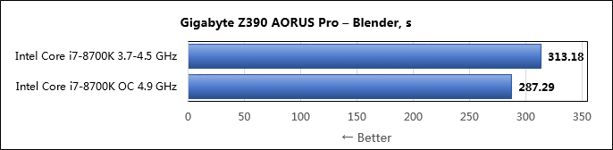

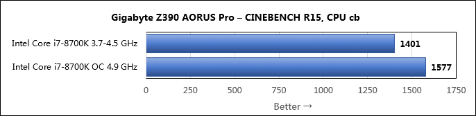
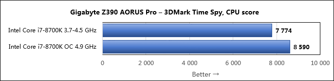
Прирост производительности от разгона процессора на Gigabyte Z390 Aorus Pro составил около 10% в среднем по всем тестам. Это довольно скромное значение, особенно учитывая серьезно возросшее тепловыделение процессора и энергопотребление при разгоне.
Заключение
Совсем не выдающиеся функциональные изменения нового чипсета Intel Z390 в сравнении с предшественником в лице Intel Z370 не помешали новой Gigabyte Z390 Aorus Pro сделать заметный шаг вперед по отношению к плате предыдущего поколения серии Aorus. В первую очередь мы имеем в виду усиленную систему питания центрального процессора и массивные радиаторы на ней с тепловой трубкой. Получили свои радиаторы и накопители в портах M.2, применен еще более качественный звуковой кодек, увеличено число подключаемых к плате вентиляторов и термодатчиков, дальнейшее развитие получила и система подсветки. Преобразился интерфейс BIOS Setup, причем он стал не только более удобен внешне, но и вырос в функциональном плане. Из недостатков отметим только отсутствие индикатора POST-кодов, но это уже, по замыслу Gigabyte, прерогатива старших и более дорогих моделей. В целом плата оставила очень приятное впечатление зрелого и стабильного продукта по вполне приемлемой в нынешних реалиях стоимости.
Смотреть руководство для Gigabyte Z390 Aorus Pro ниже. Все руководства на ManualsCat.com могут просматриваться абсолютно бесплатно. Нажав кнопку «Выбор языка» вы можете изменить язык руководства, которое хотите просмотреть.

MANUALSCAT | RU
Вопросы и ответы
У вас есть вопрос о Gigabyte Z390 Aorus Pro, но вы не можете найти ответ в пользовательском руководстве? Возможно, пользователи ManualsCat.com смогут помочь вам и ответят на ваш вопрос. Заполните форму ниже — и ваш вопрос будет отображаться под руководством для Gigabyte Z390 Aorus Pro. Пожалуйста, убедитесь, что вы опишите свои трудности с Gigabyte Z390 Aorus Pro как можно более детально. Чем более детальным является ваш вопрос, тем более высоки шансы, что другой пользователь быстро ответит на него. Вам будет автоматически отправлено электронное письмо, чтобы проинформировать вас, когда кто-то из пользователей ответит на ваш вопрос.
Задать вопрос о Gigabyte Z390 Aorus Pro
- Бренд:
- Gigabyte
- Продукт:
- материнские платы
- Модель/название:
- Z390 Aorus Pro
- Тип файла:
- Доступные языки:
- английский
Сопутствующие товары Gigabyte Z390 Aorus Pro
![]()
Z390 AORUS PRO
Z390 AORUS PRO WIFI
User’s Manual
Rev. 1001
12ME-Z39PROW-1001R
|
Z390 AORUS |
Z390 AORUS |
|
PRO |
PRO WIFI |
For more product details, please visit GIGABYTE’s website.
To reduce the impacts on global warming, the packaging materials of this product are recyclable and reusable. GIGABYTE works with you to protect the environment.

Motherboard
Z390 AORUS PRO WIFI
Aug. 31, 2018
Motherboard
Z390 AORUS PRO WIFI
Aug. 31, 2018
Wireless Module Country Approvals:
— 2 —
Motherboard
Z390 AORUS PRO
Aug. 31, 2018
Motherboard
Z390 AORUS PRO
Aug. 31, 2018
Copyright
© 2018 GIGA-BYTE TECHNOLOGY CO., LTD. All rights reserved.
The trademarks mentioned in this manual are legally registered to their respective owners.
Disclaimer
Information in this manual is protected by copyright laws and is the property of GIGABYTE.
ChangestothespecificationsandfeaturesinthismanualmaybemadebyGIGABYTEwithoutpriornotice.
No part of this manual may be reproduced, copied, translated, transmitted, or published in any form or by any means without GIGABYTE’s prior written permission.
In order to assist in the use of this product, carefully read the User’s Manual.
For product-related information, check on our website at: https://www.gigabyte.com
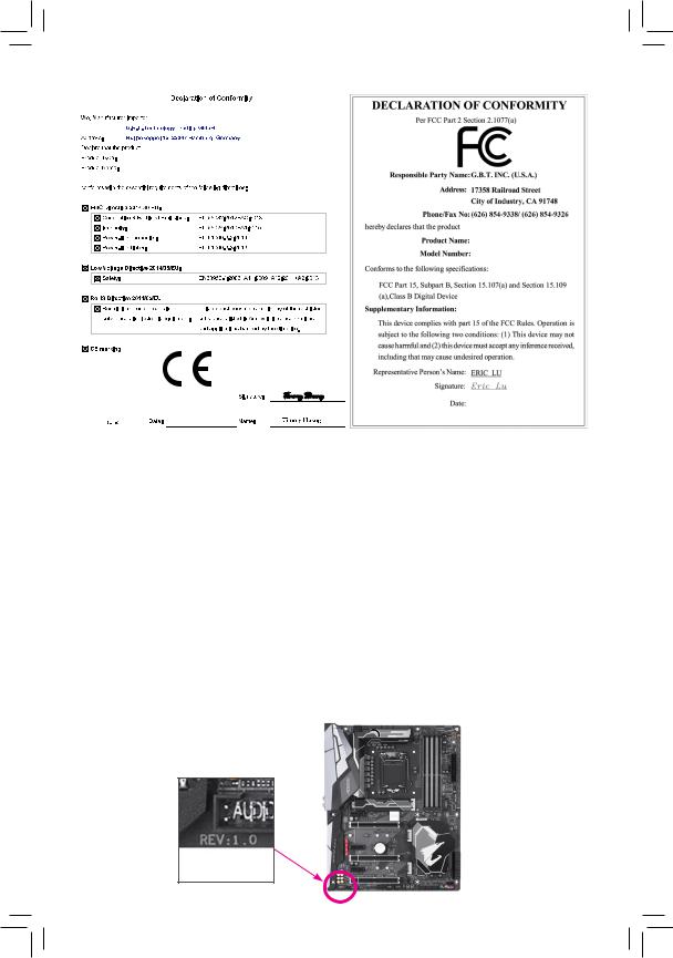
Identifying Your Motherboard Revision
The revision number on your motherboard looks like this: «REV: X.X.» For example, «REV: 1.0» means the revision of the motherboard is 1.0. Check your motherboard revision before updating motherboard BIOS, drivers, or when looking for technical information.
Example:
Table of Contents
|
Z390 AORUS PRO (WIFI) Motherboard Layout…………………………………………………….. |
5 |
|
|
Chapter 1 Hardware Installation………………………………………………………………………….. |
6 |
|
|
1-1 |
Installation Precautions…………………………………………………………………………. |
6 |
|
1-2 |
Product Specifications………………………………………………………………………….. |
7 |
|
1-3 |
Installing the CPU………………………………………………………………………………. |
11 |
|
1-4 |
Installing the Memory………………………………………………………………………….. |
11 |
|
1-5 Installing an Expansion Card……………………………………………………………….. |
12 |
|
|
1-6 Setting up AMD CrossFire™/NVIDIA® SLI™ Configuration…………………………. |
12 |
|
|
1-7 |
Back Panel Connectors………………………………………………………………………. |
13 |
|
1-8 |
Internal Connectors……………………………………………………………………………. |
15 |
|
Chapter 2 BIOS Setup……………………………………………………………………………………… |
25 |
|
|
2-1 |
Startup Screen…………………………………………………………………………………… |
25 |
|
2-2 |
The Main Menu………………………………………………………………………………….. |
26 |
|
2-3 |
M.I.T…………………………………………………………………………………………………. |
27 |
|
2-4 |
System……………………………………………………………………………………………… |
33 |
|
2-5 |
BIOS………………………………………………………………………………………………… |
34 |
|
2-6 |
Peripherals………………………………………………………………………………………… |
37 |
|
2-7 |
Chipset……………………………………………………………………………………………… |
40 |
|
2-8 |
Power……………………………………………………………………………………………….. |
41 |
|
2-9 |
Save & Exit……………………………………………………………………………………….. |
43 |
|
Chapter 3 Appendix…………………………………………………………………………………………. |
44 |
|
|
3-1 Configuring a RAID Set………………………………………………………………………. |
44 |
|
|
3-2 Installing an Intel® Optane™ Memory…………………………………………………….. |
46 |
|
|
3-3 |
Drivers Installation……………………………………………………………………………… |
48 |
|
Regulatory Statements…………………………………………………………………………………. |
49 |
|
|
Contact Us………………………………………………………………………………………………….. |
56 |
— 4 —
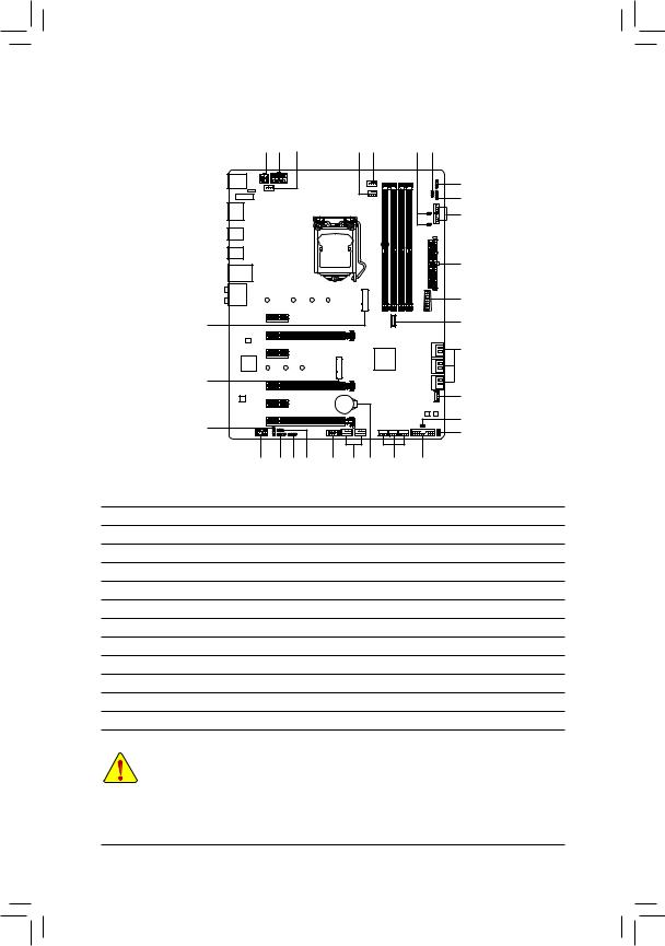
Z390 AORUS PRO (WIFI) Motherboard Layout
|
R_USB1 USB 2.0 |
ATX_12V_2X4 |
|||||
|
Hub(Note 2) |
SYS_FAN1 |
|||||
|
CNVI (Note 1) |
ATX_12V_2X2 |
|||||
|
WIFI MODULE (Note 1) |
||||||
|
HDMI |
LGA1151 |
|||||
|
R USB30 |
||||||
|
TYPEC |
||||||
|
USB31 |
||||||
|
USB30_LAN |
||||||
|
AUDIO |
110 |
80 |
60 |
42 |
||
|
PCIEX1_1 |
||||||
|
PCIEX16 |
Z390 AORUS PRO (WIFI) |
|||||
|
Intel® GbE |
||||||
|
LAN |
||||||
|
PCIEX1_2 |
||||||
|
iTE® |
80 |
60 |
42 |
M2M |
||
|
Super I/O |
||||||
PCIEX8
|
CPU_FAN |
SW2 LED2D |
||
|
V |
LED C2 |
FAN5SYS_ PUMP |
|
|
CPU_OPT |
DLED |
||
|
EC_TEMP1 |
|||
|
EC_TEMP2 |
_ |
||
|
SYSFAN6 PUMP |
|||
|
ATX |
|||
|
M2A DDR4 B1 DDR4 B2 |
F USB30 |
|
USB30C |
DDR4 A1 DDR4 A2 |
|
F |
|
|
1 0 |
|
|
Intel® Z390 |
3 2 |
|
5 4 |
|
|
SATA3 |
|
CODEC |
PCIEX1_3 |
||
|
BAT |
|||
|
PCIEX4 |
|||
|
F_AUDIO |
DLED_V_SW1 |
USB |
|
|
Box Contents |
SPDIF_O LED_C1 |
TPM F_USB2 F_USB1 |
|
|
D_LED1 |
|
THB C |
|||
|
M_BIOS |
|||
|
B_BIOS |
|||
|
SYS_FAN2 SYS_FAN4 |
CLR_CMOS |
||
|
2.0 Hub |
|||
|
SYS_FAN3 |
F_PANEL CPU |
DRAM |
|
|
VGA |
BOOT |
|
55 |
Z390 AORUS PRO or Z390 AORUS PRO WIFI motherboard |
||
|
55 |
Motherboard driver disk |
55 |
One digital LED strip adapter cable |
|
55 |
User’s Manual |
55 |
One RGB LED strip extension cable |
|
55 |
Quick Installation Guide |
55 |
One Wi-Fi antenna (Note 1) |
|
55 |
Four SATA cables |
55 |
One G Connector |
|
55 |
M.2 screw(s)/M.2 standoff(s) |
55 |
Two thermistor cables |
*The box contents above are for reference only and the actual items shall depend on the product package you obtain. The box contents are subject to change without notice.
(Note 1) Only for the Z390 AORUS PRO WIFI. (Note 2) The chip is on the back of the motherboard.
— 5 —
Chapter 1 Hardware Installation
1-1 Installation Precautions
The motherboard contains numerous delicate electronic circuits and components which can become damaged as a result of electrostatic discharge (ESD). Prior to installation, carefully read the user’s manual and follow these procedures:
•• Prior to installation, make sure the chassis is suitable for the motherboard.
•• Prior to installation, do not remove or break motherboard S/N (Serial Number) sticker or warranty sticker provided by your dealer. These stickers are required for warranty validation.
•• Always remove the AC power by unplugging the power cord from the power outlet before installing or removing the motherboard or other hardware components.
•• When connecting hardware components to the internal connectors on the motherboard, make sure they are connected tightly and securely.
•• When handling the motherboard, avoid touching any metal leads or connectors.
•• It is best to wear an electrostatic discharge (ESD) wrist strap when handling electronic components such as a motherboard, CPU or memory. If you do not have an ESD wrist strap, keep your hands dry and first touch a metal object to eliminate static electricity.
•• Prior to installing the motherboard, please have it on top of an antistatic pad or within an electrostatic shielding container.
•• Before connecting or unplugging the power supply cable from the motherboard, make sure the power supply has been turned off.
•• Before turning on the power, make sure the power supply voltage has been set according to the local voltage standard.
•• Before using the product, please verify that all cables and power connectors of your hardware components are connected.
•• To prevent damage to the motherboard, do not allow screws to come in contact with the motherboard circuit or its components.
•• Make sure there are no leftover screws or metal components placed on the motherboard or within the computer casing.
•• Do not place the computer system on an uneven surface.
•• Do not place the computer system in a high-temperature or wet environment.
•• Turning on the computer power during the installation process can lead to damage to system components as well as physical harm to the user.
•• If you are uncertain about any installation steps or have a problem related to the use of the product, please consult a certified computer technician.
•• If you use an adapter, extension power cable, or power strip, ensure to consult with its installation and/or grounding instructions.
— 6 —

|
1-2 |
Product Specifications |
|||
|
CPU |
Support for Intel 9000 Processors and 8th Generation Intel® Core™ i7 processors/ |
|||
|
Intel® Core™ i5 processors/Intel® Core™ i3 processors/Intel® Pentium® processors/ |
||||
|
Intel® Celeron® processors in the LGA1151 package |
||||
|
(Go to GIGABYTE’s website for the latest CPU support list.) |
||||
|
L3 cache varies with CPU |
||||
|
Chipset |
Intel® Z390 Express Chipset |
|||
|
Memory |
4 x DDR4 DIMM sockets supporting up to 64 GB of system memory |
|||
|
Dual channel memory architecture |
||||
|
Support for DDR4 2666/2400/2133 MHz memory modules |
||||
|
Support for ECC Un-buffered DIMM 1Rx8/2Rx8 memory modules (operate in |
||||
|
non-ECC mode) |
||||
|
Support for non-ECC Un-buffered DIMM 1Rx8/2Rx8/1Rx16 memory modules |
||||
|
Support for Extreme Memory Profile (XMP) memory modules |
||||
|
(Go to GIGABYTE’s website for the latest supported memory speeds and memory |
||||
|
modules.) |
||||
|
Onboard |
Integrated Graphics Processor-Intel® HD Graphics support: |
|||
|
Graphics |
— |
1 x HDMI port, supporting a maximum resolution of 4096×2160@30 Hz |
||
|
* Support for HDMI 1.4 version and HDCP 2.2. |
||||
|
Maximum shared memory of 1 GB |
||||
|
Audio |
Realtek® ALC1220-VB codec |
|||
|
* The back panel line out jack supports DSD audio. |
||||
|
High Definition Audio |
||||
|
2/4/5.1/7.1-channel |
||||
|
Support for S/PDIF Out |
||||
|
LAN |
Intel® GbE LAN chip (10/100/1000 Mbit) |
|||
|
Wireless |
Intel® CNVi interface 802.11a/b/g/n/ac, supporting 2.4/5 GHz Dual-Band |
|||
|
Communication |
BLUETOOTH 5 |
|||
|
Module (Note) |
Support for 11ac 160 MHz wireless standard and up to 1.73 Gbps data rate |
|||
|
* Actual data rate may vary depending on environment and equipment. |
||||
|
Expansion Slots |
1 x PCI Express x16 slot, running at x16 (PCIEX16) |
|||
|
* For optimum performance, if only one PCI Express graphics card is to be installed, |
||||
|
be sure to install it in the PCIEX16 slot. |
||||
|
1 x PCI Express x16 slot, running at x8 (PCIEX8) |
||||
|
* The PCIEX8 slot shares bandwidth with the PCIEX16 slot. When the PCIEX8 slot is |
||||
|
populated, the PCIEX16 slot operates at up to x8 mode. |
||||
|
1 x PCI Express x16 slot, running at x4 (PCIEX4) |
||||
|
3 x PCI Express x1 slots |
||||
|
(All of the PCI Express slots conform to PCI Express 3.0 standard.) |
||||
|
1 x M.2 Socket 1 connector for an Intel® CNVi wireless module (CNVI) (Note) |
||||
|
Multi-Graphics |
Support for NVIDIA® Quad-GPU SLI™ and 2-Way NVIDIA® SLI™ technologies |
|||
|
Technology |
Support for AMD Quad-GPU CrossFire™ and 3-Way/2-Way AMD CrossFire™ |
|||
|
technologies |
||||
|
(Note) |
Only for the Z390 AORUS PRO WIFI. |
|||
|
— 7 — |
|
Storage Interface |
Chipset: |
||
|
— |
1 x M.2 connector (Socket 3, M key, type 2242/2260/2280/22110 SATA and |
||
|
PCIe x4/x2 SSD support) (M2A) |
|||
|
— |
1 x M.2 connector (Socket 3, M key, type 2242/2260/2280 SATA and PCIe |
||
|
x4/x2 SSD support, prepared for Intel® Hybrid SSD) (M2M) |
|||
|
— |
6 x SATA 6Gb/s connectors |
||
|
— |
Support for RAID 0, RAID 1, RAID 5, and RAID 10 |
||
|
* Refer to «1-8 Internal Connectors,» for the installation notices for the M.2 and SATA |
|||
|
connectors. |
|||
|
Intel® Optane™ Memory Ready |
|||
|
USB |
Chipset: |
||
|
— |
1 x USB Type-C™ port with USB 3.1 Gen 2 support on the back panel |
||
|
— |
1 x USB Type-C™ port with USB 3.1 Gen 1 support, available through the |
||
|
internal USB header |
|||
|
— |
2 x USB 3.1 Gen 2 Type-A ports (red) on the back panel |
||
|
— |
5 x USB 3.1 Gen 1 ports (3 ports on the back panel, 2 ports available through |
||
|
the internal USB header) |
|||
|
Chipset+USB 2.0 Hub: |
|||
|
— |
8 x USB 2.0/1.1 ports (4 ports on the back panel, 4 ports available through |
||
|
the internal USB headers) |
|||
|
Internal |
1 x 24-pin ATX main power connector |
||
|
Connectors |
1 x 8-pin ATX 12V power connector |
1 x 4-pin ATX 12V power connector
1 x CPU fan header
1 x water cooling CPU fan header
4 x system fan headers
2 x system fan/water cooling pump headers
2 x digital LED strip headers
2 x digital LED strip power select jumpers
2 x RGB LED strip headers
6 x SATA 6Gb/s connectors
2 x M.2 Socket 3 connectors
1 x front panel header
1 x front panel audio header
1 x S/PDIF Out header
1 x USB Type-C™ port, with USB 3.1 Gen 1 support
1 x USB 3.1 Gen 1 header
2 x USB 2.0/1.1 headers
1 x Thunderbolt™ add-in card connector
1 x Trusted Platform Module (TPM) header (2×6 pin, for the GC-TPM2.0_S module only)
1 x Clear CMOS jumper
2 x temperature sensor headers
—8 —
|
Back Panel |
4 x USB 2.0/1.1 ports |
|
Connectors |
2 x SMA antenna connectors (2T2R) (Note) |
|
1 x HDMI port |
|
|
1 x USB Type-C™ port, with USB 3.1 Gen 2 support |
|
|
2 x USB 3.1 Gen 2 Type-A ports (red) |
|
|
3 x USB 3.1 Gen 1 ports |
|
|
1 x RJ-45 port |
|
|
1 x optical S/PDIF Out connector |
|
|
5 x audio jacks |
|
|
I/O Controller |
iTE® I/O Controller Chip |
Voltage detection
Temperature detection
Fan speed detection
Water cooling flow rate detection
Overheating warning
Fan fail warning
Fan speed control
*Whether the fan (pump) speed control function is supported will depend on the fan (pump) you install.
|
BIOS |
2 x 128 Mbit flash |
|
|
Use of licensed AMI UEFI BIOS |
Support for DualBIOS™
PnP 1.0a, DMI 2.7, WfM 2.0, SM BIOS 2.7, ACPI 5.0
Unique Features Support for APP Center
*Available applications in APP Center may vary by motherboard model. Supported functions of each application may also vary depending on motherboard specifications.
—3D OSD
—@BIOS
—AutoGreen
—Cloud Station
—EasyTune
—Easy RAID
—Fast Boot
—Game Boost
—ON/OFF Charge
—Platform Power Management
—RGB Fusion
(Note) Only for the Z390 AORUS PRO WIFI.
— 9 —
|
Unique Features |
— |
Smart Backup |
||
|
— |
Smart Keyboard |
|||
|
— |
Smart TimeLock |
|||
|
— |
Smart HUD |
|||
|
— |
System Information Viewer |
|||
|
— |
Smart Survey |
|||
|
— |
USB Blocker |
|||
|
Support for Q-Flash |
||||
|
Support for Xpress Install |
||||
|
Bundled |
Norton® Internet Security (OEM version) |
|||
|
Software |
cFosSpeed |
|||
|
Operating |
Support for Windows 10 64-bit |
|||
|
System |
||||
|
Form Factor |
ATX Form Factor; 30.5cm x 24.4cm |
*GIGABYTE reserves the right to make any changes to the product specifications and product-related information without prior notice.
|
Z390 AORUS PRO |
Z390 AORUS PRO |
|
WIFI |
Please visit GIGABYTE’s website for support lists of CPU, memory modules, SSDs, and M.2 devices.
Please visit the SupportUtility List page on GIGABYTE’s website to download the latest version of apps.
— 10 —
![]()
|
1-3 |
Installing the CPU |
|
|
Read the following guidelines before you begin to install the CPU: |
||
|
•• |
Make sure that the motherboard supports the CPU. |
|
|
(Go to GIGABYTE’s website for the latest CPU support list.) |
||
|
•• |
Always turn off the computer and unplug the power cord from the power outlet before installing the |
|
|
•• |
CPU to prevent hardware damage. |
|
|
Locate the pin one of the CPU. The CPU cannot be inserted if oriented incorrectly. (Or you may |
||
|
•• |
locate the notches on both sides of the CPU and alignment keys on the CPU socket.) |
|
|
Apply an even and thin layer of thermal grease on the surface of the CPU. |
||
|
•• |
Do not turn on the computer if the CPU cooler is not installed, otherwise overheating and damage |
|
|
•• |
of the CPU may occur. |
|
|
Set the CPU host frequency in accordance with the CPU specifications. It is not recommended |
||
|
that the system bus frequency be set beyond hardware specifications since it does not meet the |
||
|
standard requirements for the peripherals. If you wish to set the frequency beyond the standard |
||
|
specifications, please do so according to your hardware specifications including the CPU, graphics |
||
|
card, memory, hard drive, etc. |
Installing the CPU
Locate the alignment keys on the motherboard CPU socket and the notches on the CPU.
|
LGA1151 CPU Socket |
LGA1151 CPU |
||
|
Alignment Key |
Alignment Key |
Notch |
Notch |
|
Pin One Corner of the CPU Socket |
Triangle Pin One Marking on the CPU |
Do not remove the CPU socket cover before inserting the CPU. It may pop off from the load plate automatically during the process of re-engaging the lever after you insert the CPU.
1-4 Installing the Memory
Read the following guidelines before you begin to install the memory:
•• Make sure that the motherboard supports the memory. It is recommended that memory of the same capacity, brand, speed, and chips be used.
(Go to GIGABYTE’s website for the latest supported memory speeds and memory modules.)
•• Always turn off the computer and unplug the power cord from the power outlet before installing the memory to prevent hardware damage.
•• Memory modules have a foolproof design. A memory module can be installed in only one direction. If you are unable to insert the memory, switch the direction.
Dual Channel Memory Configuration
This motherboard provides four memory sockets and supports Dual Channel Technology. After the memory is installed, the BIOS will automatically detect the specifications and capacity of the memory. Enabling Dual
Channel memory mode will double the original memory bandwidth.
The four memory sockets are divided into two channels and each channel has two memory sockets as following:
Please visit GIGABYTE’s website for details on hardware installation.
— 11 —
Channel A: DDR4_A1, DDR4_A2Channel B: DDR4_B1, DDR4_B2
Dual Channel Memory Configurations Table
|
DDR4_B1 |
DDR4_B2 |
DDR4_A1 |
DDR4_A2 |
|
|
2 Modules |
— — |
DS/SS |
— — |
DS/SS |
|
DS/SS |
— — |
DS/SS |
— — |
|
|
4 Modules |
DS/SS |
DS/SS |
DS/SS |
DS/SS |
(SS=Single-Sided, DS=Double-Sided, «- -«=No Memory)
Due to CPU limitations, read the following guidelines before installing the memory in Dual Channel mode.
1.Dual Channel mode cannot be enabled if only one memory module is installed.
2.When enabling Dual Channel mode with two or four memory modules, it is recommended that memory of the same capacity, brand, speed, and chips be used.
1-5 Installing an Expansion Card
Read the following guidelines before you begin to install an expansion card:
•• Make sure the motherboard supports the expansion card. Carefully read the manual that came with your expansion card.
•• Always turn off the computer and unplug the power cord from the power outlet before installing an expansion card to prevent hardware damage.
1-6 Setting up AMD CrossFire™/NVIDIA® SLI™ Configuration
A.System Requirements
— Windows 10 64-bit operating system
— A CrossFire/SLI-supported motherboard with two or more PCI Express x16 slots and correct driver — CrossFire/SLI-ready graphics cards of identical brand and chip and correct driver
(For the latest GPUs that support the 3-way CrossFire technology, please refer to the AMD website.) (Note 1) — CrossFire (Note 2)/SLI bridge connectors
— A power supply with sufficient power is recommended (Refer to the manual of your graphics cards for the power requirement)
B.Connecting the Graphics Cards
Step 1:
Observe the steps in «1-5 Installing an Expansion Card» and install CrossFire/SLI graphics cards on the PCI
Express x16 slots. (To set up a 2-Way configuration, we recommend installing the graphics cards on the
PCIEX16 and PCIEX8 slots.) Step 2:
Insert the CrossFire (Note 2)/SLI bridge connectors in the CrossFire/SLI gold edge connectors on top of the cards. Step 3:
Plug the display cable into the graphics card on the PCIEX16 slot.
C. Configuring the Graphics Card Driver
C-1. To Enable CrossFire Function
After installing the graphics card driver in the operating system, go to the AMD RADEON SETTINGS screen. Browse to GamingGlobal Settings and ensure AMD CrossFire is set to On.
C-2. To Enable SLI Function
After installing the graphics card driver in the operating system, go to the NVIDIA Control Panel. Browse to the
Configure SLI, Surround, Physx screen and ensure Maximize 3D performance is enabled.
(Note 1) When using dual core graphics cards, only 2-way is supported.
(Note 2) The bridge connector(s) may be needed or not depending on your graphics cards.
Procedure and driver screen for enabling CrossFire/SLI technology may differ by graphics cards and driver version. Refer to the manual that came with your graphics cards for more information about enabling CrossFire/SLI technology.
— 12 —
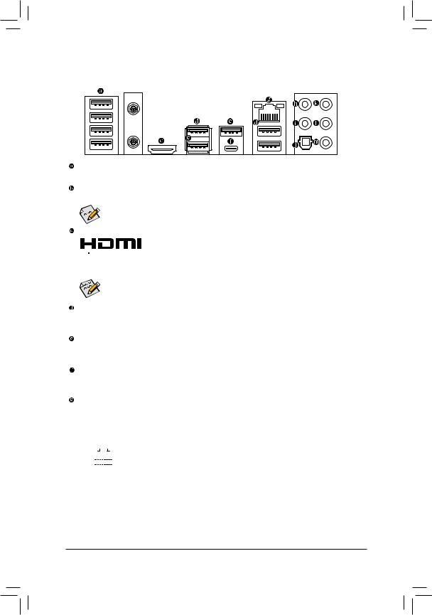
1-7 Back Panel Connectors
 (Note)
USB 2.0/1.1 Port
The USB port supports the USB 2.0/1.1 specification. Use this port for USB devices.
SMA Antenna Connectors (2T2R) (Note)
Use this connector to connect an antenna.

 Tighten the antenna cables to the antenna connectors and then move the antenna to a place
where the signal is good.
HDMI Port
 The HDMI port supports HDCP 2.2 and Dolby TrueHD and DTS HD Master Audio


 formats. It also supports up to 192KHz/16bit 8-channel LPCM audio output. You can use this port to connect your HDMI-supported monitor. The maximum supported resolution is 4096×2160@30 Hz, but the actual resolutions supported are dependent on the monitor being used.
After installing the HDMI device, make sure to set the default sound playback device to HDMI. (The item name may differ depending on your operating system.)
USB 3.1 Gen 1 Port
The USB 3.1 Gen 1 port supports the USB 3.1 Gen 1 specification and is compatible to the USB 2.0 specification. Use this port for USB devices.
USB 3.1 Gen 2 Type-A Port (Red)
The USB 3.1 Gen 2 Type-A port supports the USB 3.1 Gen 2 specification and is compatible to the USB 3.1 Gen 1 and USB 2.0 specification. Use this port for USB devices.
USB Type-C™ Port
The reversible USB port supports the USB 3.1 Gen 2 specification and is compatible to the USB 3.1 Gen 1 and USB 2.0 specification. Use this port for USB devices.
RJ-45 LAN Port
The Gigabit Ethernet LAN port provides Internet connection at up to 1 Gbps data rate. The following describes the states of the LAN port LEDs.
|
Connection/ |
Connection/Speed LED: |
Activity LED: |
|||||||||||||||||
|
Speed LED |
Activity LED |
||||||||||||||||||
|
State |
Description |
State |
Description |
||||||||||||||||
|
Orange |
1 Gbps data rate |
Blinking |
Data transmission or receiving is occurring |
||||||||||||||||
|
Green |
100 Mbps data rate |
On |
No data transmission or receiving is occurring |
||||||||||||||||
|
Off |
10 Mbps data rate |
||||||||||||||||||
|
LAN Port |
|||||||||||||||||||
(Note) Only for the Z390 AORUS PRO WIFI.
— 13 —
Center/Subwoofer Speaker Out
Use this audio jack to connect center/subwoofer speakers.
Rear Speaker Out
Use this audio jack to connect rear speakers.
Optical S/PDIF Out Connector
This connector provides digital audio out to an external audio system that supports digital optical audio. Before using this feature, ensure that your audio system provides an optical digital audio in connector.
Line In/Side Speaker Out
The line in jack. Use this audio jack for line in devices such as an optical drive, walkman, etc.
Line Out/Front Speaker Out
The line out jack. This jack supports audio amplifying function. For better sound quality, it is recommended that you connect your headphone/speaker to this jack (actual effects may vary by the device being used).
Mic In/Side Speaker Out
The Mic in jack.
Audio Jack Configurations:
|
Jack |
Headphone/ |
4-channel |
5.1-channel |
7.1-channel |
|
|
2-channel |
|||||
|
Center/Subwoofer Speaker Out |
a |
a |
|||
|
Rear Speaker Out |
a |
a |
a |
||
|
Line In/Side Speaker Out |
a |
||||
|
Line Out/Front Speaker Out |
a |
a |
a |
a |
|
|
Mic In/Side Speaker Out |
a |
||||

 If you want to install a Side Speaker, you need to retask either the Line in or Mic in jack to be Side Speaker out through the audio driver.
•• When removing the cable connected to a back panel connector, first remove the cable from your device and then remove it from the motherboard.
•• When removing the cable, pull it straight out from the connector. Do not rock it side to side to prevent an electrical short inside the cable connector.
Please visit GIGABYTE’s website for details on configuring the audio software.
— 14 —
|
1-8 |
Internal Connectors |
|||||||||
|
1 |
1 |
4 |
6 |
3 |
7 |
10 |
||||
|
9 |
||||||||||
|
8 |
||||||||||
|
5 |
||||||||||
|
2 |
||||||||||
|
17 |
||||||||||
|
12 |
16 |
|||||||||
|
11 |
||||||||||
|
12 |
||||||||||
|
20 |
||||||||||
|
15 |
21 |
|||||||||
|
23 |
||||||||||
|
14 |
9 |
8 |
10 |
19 |
18 |
22 |
4 |
13 |
||
|
1) |
ATX_12V_2X2/ATX_12V_2X4 |
13) |
F_PANEL |
|||||||
|
2) |
ATX |
14) |
F_AUDIO |
|||||||
|
3) |
CPU_FAN |
15) |
SPDIF_O |
|||||||
|
4) |
SYS_FAN1/2/3/4 |
16) |
F_USB30C |
|||||||
|
5) |
SYS_FAN5/6_PUMP |
17) |
F_USB30 |
|||||||
|
6) |
CPU_OPT |
18) |
F_USB1/F_USB2 |
|||||||
|
7) |
EC_TEMP1/EC_TEMP2 |
19) |
TPM |
|||||||
|
|
LED_C1/LED_C2 |
20) |
THB_C |
|||||||
|
9) |
D_LED1/D_LED2 |
21) |
CLR_CMOS |
|||||||
|
10) |
DLED_V_SW1/DLED_V_SW2 |
22) |
BAT |
|||||||
|
11) |
SATA3 0/1/2/3/4/5 |
23) |
CPU/DRAM/VGA/BOOT |
|||||||
|
12) |
M2A/M2M |
Read the following guidelines before connecting external devices:
•• First make sure your devices are compliant with the connectors you wish to connect.
•• Before installing the devices, be sure to turn off the devices and your computer. Unplug the power cord from the power outlet to prevent damage to the devices.
•• After installing the device and before turning on the computer, make sure the device cable has been securely attached to the connector on the motherboard.
— 15 —
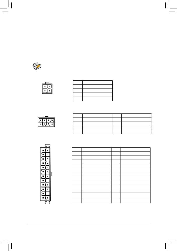
1/2)ATX_12V_2X2/ATX_12V_2X4/ATX (2×2, 2×4, 12V Power Connectors and 2×12 Main
Power Connector)
With the use of the power connector, the power supply can supply enough stable power to all the components on the motherboard. Before connecting the power connector, first make sure the power supply is turned off and all devices are properly installed. The power connector possesses a foolproof design. Connect the power supply cable to the power connector in the correct orientation.
The 12V power connector mainly supplies power to the CPU. If the 12V power connector is not connected, the computer will not start.
To meet expansion requirements, it is recommended that a power supply that can withstand high power consumption be used (500W or greater). If a power supply is used that does not provide the required power, the result can lead to an unstable or unbootable system.
|
ATX_12V_2X2: |
||||||
|
Pin No. |
Definition |
|||||
|
3 |
4 |
1 |
GND |
|||
|
1 |
2 |
2 |
GND |
|||
|
ATX_12V_2X2 |
3 |
+12V |
||||
|
4 |
+12V |
|||||
|
ATX_12V_2X4: |
||||||
|
Pin No. |
Definition |
Pin No. |
Definition |
|||
|
5 |
8 |
1 |
GND (Only for 2×4-pin 12V) |
5 |
+12V (Only for 2×4-pin 12V) |
|
|
1 |
4 |
2 |
GND (Only for 2×4-pin 12V) |
6 |
+12V (Only for 2×4-pin 12V) |
|
|
ATX_12V_2X4 |
3 |
GND |
7 |
+12V |
||
|
4 |
GND |
8 |
+12V |
|||
|
ATX: |
||||||
|
12 |
24 |
Pin No. |
Definition |
Pin No. |
Definition |
|
|
1 |
3.3V |
13 |
3.3V |
|||
|
2 |
3.3V |
14 |
-12V |
|||
|
3 |
GND |
15 |
GND |
|||
|
4 |
+5V |
16 |
PS_ON (soft On/Off) |
|||
|
5 |
GND |
17 |
GND |
|||
|
6 |
+5V |
18 |
GND |
|||
|
7 |
GND |
19 |
GND |
|||
|
8 |
Power Good |
20 |
NC |
|||
|
9 |
5VSB (stand by +5V) |
21 |
+5V |
|||
|
10 |
+12V |
22 |
+5V |
|||
|
11 |
+12V (Only for 2×12-pin |
23 |
+5V (Only for 2×12-pin ATX) |
|||
|
1 |
13 |
12 |
ATX) |
24 |
GND (Only for 2×12-pin ATX) |
|
|
3.3V (Only for 2×12-pin ATX) |
ATX
— 16 —
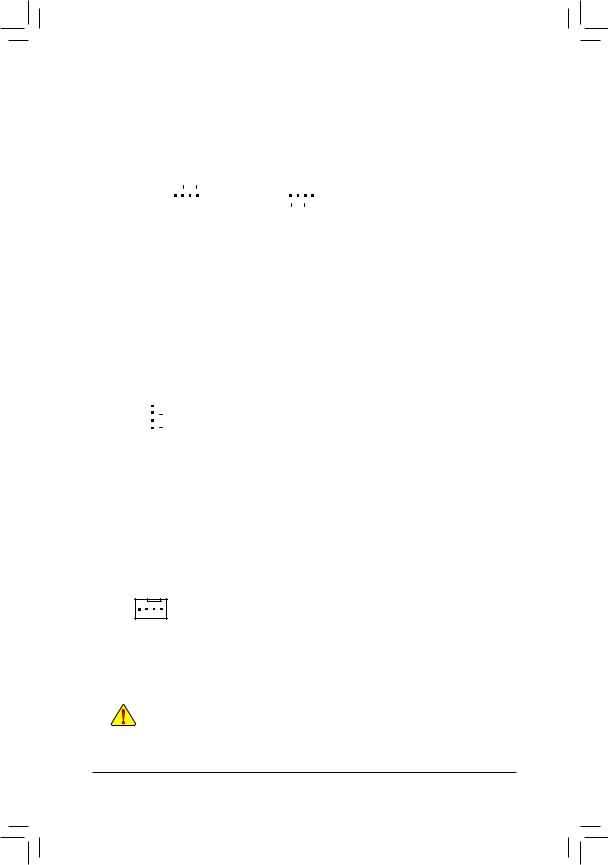
3/4) CPU_FAN/SYS_FAN1/2/3/4 (Fan Headers)
All fan headers on this motherboard are 4-pin. Most fan headers possess a foolproof insertion design. When connecting a fan cable, be sure to connect it in the correct orientation (the black connector wire is the ground wire). The speed control function requires the use of a fan with fan speed control design. For optimum heat dissipation, it is recommended that a system fan be installed inside the chassis.
|
Pin No. |
Definition |
||||||||||
|
1 |
1 |
1 |
GND |
||||||||
|
2 |
Voltage Speed Control |
||||||||||
|
CPU_FAN/SYS_FAN1 |
SYS_FAN2/SYS_FAN3/SYS_FAN4 |
3 |
Sense |
||||||||
|
4 |
PWM Speed Control |
5)SYS_FAN5/6_PUMP (System Fan/Water Cooling Pump Headers)
The fan/pump headers are 4-pin and possess a foolproof insertion design. Most fan headers possess a foolproof insertion design. When connecting a fan cable, be sure to connect it in the correct orientation (the black connector wire is the ground wire). The speed control function requires the use of a fan with fan speed control design. For optimum heat dissipation, it is recommended that a system fan be installed inside the chassis. The header also provides speed control for a water cooling pump, refer to Chapter 2, «BIOS Setup,» «M.I.T.,» for more information.
|
Pin No. |
Definition |
||
|
1 |
GND |
||
|
2 |
Voltage Speed Control |
||
|
1 |
3 |
Sense |
|
|
4 |
PWM Speed Control |
6)CPU_OPT (Water Cooling CPU Fan Header)
The fan header is 4-pin and possesses a foolproof insertion design. Most fan headers possess a foolproof insertion design. When connecting a fan cable, be sure to connect it in the correct orientation (the black connector wire is the ground wire). The speed control function requires the use of a fan with fan speed control design.
|
Pin No. |
Definition |
|
|
1 |
1 |
GND |
|
2 |
Voltage Speed Control |
|
|
3 |
Sense |
|
|
4 |
PWM Speed Control |
•• Be sure to connect fan cables to the fan headers to prevent your CPU and system from overheating. Overheating may result in damage to the CPU or the system may hang.
•• Thesefanheadersarenotconfigurationjumperblocks.Donotplaceajumpercapontheheaders.
— 17 —
 Loading…