Задача обеспечения стабильного питания далеко не всегда сводится к покупке ИБП с возможностью автономного питания нагрузки в условиях отсутствия сетевого напряжения. Особенно в домашних условиях, и особенно теперь, когда многие пользуются ноутбуками и другими мобильными устройствами, способными вполне сносно переносить даже длительное отключение внешнего питания. Другое дело, что само по себе качество сетевого питания вдалеке от больших городов России зачастую все еще оставляет желать лучшего. Заниженное, а иногда и завышенное напряжение может быть объективным фактором, с которым приходится мириться. Автоматические трансформаторы используются для коррекции этого недостатка вашей среды обитания. В данном обзоре мы рассмотрим такой продукт компании APC.
Описание
У нас на тестировании побывала младшая модель, на 600 В·А, а в линейке также имеется версия мощностью 1200 В·А. Производитель заявляет следующие характеристики изделия:
| Технические характеристики | |
|
Входное напряжение, частота |
160—300 В, 47—63 Гц |
|
Выходное (при работе от батарей) напряжение, частота |
220/230/240 В (настраиваемое) |
|
Автоматический регулятор напряжения |
да |
|
Выходная мощность (заявленная) |
600 В·А (ток не более 2,6 А) |
|
Выходная мощность (активная, протестированная) |
700 Вт |
|
Форма выходного сигнала |
синусоида |
|
Время автономной работы от батареи для стандартного ПК |
— |
|
Функция запуска оборудования без подключения к электросети |
— |
|
Тип, напряжение и емкость батареи |
— |
|
Время перезарядки батареи |
— |
|
Индикация |
— |
|
Звуковая сигнализация |
— |
|
Самодиагностика |
при включении |
|
Фильтрация импульсных помех |
300 Дж, 55 дБ |
|
Защита от перегрузки |
Автоматический предохранитель |
|
Выходные разъемы |
3 евророзетки |
|
Защита линий передачи данных |
нет |
|
Интерфейс |
— |
|
Размеры (Ш×Г×В) |
118×214×148 мм |
|
Вес |
3,1 кг |
|
Шум (заявленный) |
— |
|
Условия работы |
влажность 0—95% (без конденсации) температура от 0 до +45 °C |
|
Описание на сайте производителя |
APC Line-R 600VA |
Комплект поставки:
- инструкция по эксплуатации на русском языке
- гарантийный талон
Гарантийный срок эксплуатации: 2 года
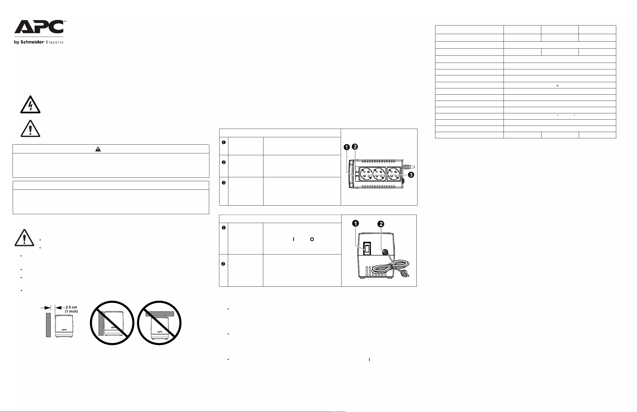
Внешний вид
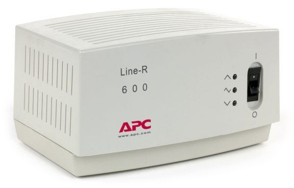
Устройство весьма компактно, не занимает даже половины объема традиционного ИБП «башенного дизайна», весит также в 2-3 раза меньше. И если не считать щелчков реле (при переключении между обмотками трансформатора), не издает никаких посторонних звуков во время работы. На лицевой стороне располагается клавиша включения и световые индикаторы, которые подскажут пользователю, какова текущая ситуация в его сети.
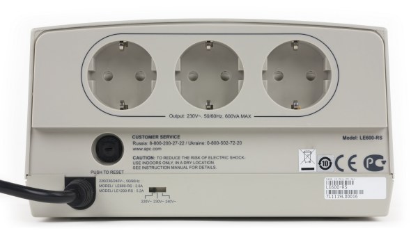
На задней панели имеются 3 стандартные евророзетки и переключатель уровня выходного напряжения. Пользователь имеет возможность выбирать из трех значений: 220, 230 и 240 В. Для защиты от перегрузки и короткого замыкания предусмотрен автоматический предохранитель.
Внутреннее устройство
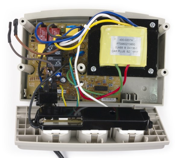
Внутри корпуса достаточно просторно: нижнюю часть занимает плата, над ней установлен главный компонент стабилизатора: трансформатор с переключаемыми обмотками.
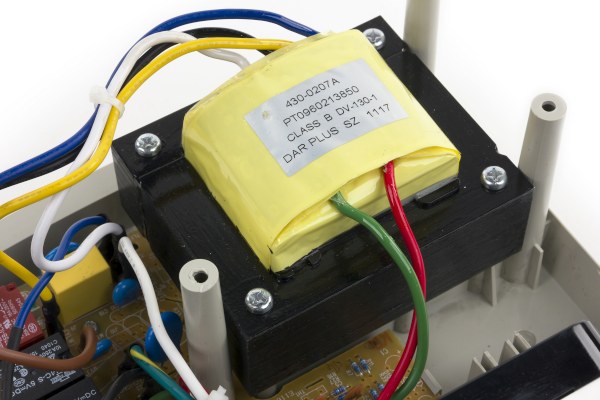
Весьма распространенная модель трансформатора, встречающаяся также в ИБП под маркой Ippon.
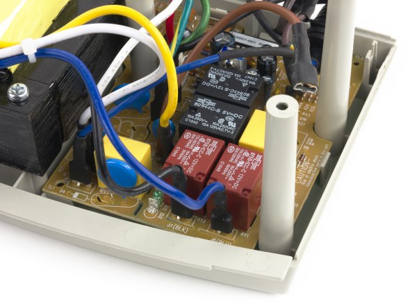
Переключением между ступенями AVR-регулятора занимаются механические реле, рассчитанные на максимальный ток 10-16 А, что означает солидный запас прочности.
Тестирование
Мы использовали регулируемый автотрансформатор (ЛАТР), для того чтобы определить пороги переключения и фактическое напряжение на выходах при входном напряжении в диапазоне 0—262 В. Тестирование проводилось при подключенной активной нагрузке около 100 Вт.
При установленном выходном напряжении 220 В:
| Входное напряжение (при повышении от 0 до 267 В) | Выходное напряжение | Режим работы |
| <175 В | 0 В | — |
| 175—187 В | 227—229 В | повышение (AVR 2 ст.) |
| 188—210 В | 207—235 В | повышение (AVR 1 ст.) |
| 210—240 В | 210—240 В | напрямую от сети |
| 241—267 В | 220—228 В | понижение (AVR) |
| Входное напряжение (при понижении от 267 до 0 В) | Выходное напряжение | Режим работы |
| 267—232 В | 228—204 В | понижение (AVR) |
| 230—206 В | 230—206 В | напрямую от сети |
| 206—179 В | 225—201 В | повышение (AVR 1 ст.) |
| 178—158 В | 227—195 В | повышение (AVR 2 ст.) |
| <158 В | 0 В | — |
При установленном выходном напряжении 230 В:
| Входное напряжение (при повышении от 0 до 267 В) | Выходное напряжение | Режим работы |
| <185 В | 0 В | — |
| 185—197 В | 242—245 В | повышение (AVR 2 ст.) |
| 198—220 В | 220—243 В | повышение (AVR 1 ст.) |
| 220—250 В | 220—250 В | напрямую от сети |
| 251—267 В | 220—234 В | понижение (AVR) |
| Входное напряжение (при понижении от 267 до 0 В) | Выходное напряжение | Режим работы |
| 267—245 В | 234—214 В | понижение (AVR) |
| 244—218 В | 244—218 В | напрямую от сети |
| 217—199 В | 242—215 В | повышение (AVR 1 ст.) |
| 198—155 В | 237—200 В | повышение (AVR 2 ст.) |
| <155 В | 0 В | — |
При установленном выходном напряжении 240 В:
| Входное напряжение (при повышении от 0 до 267 В) | Выходное напряжение | Режим работы |
| <170 В | 0 В | — |
| 170—203 В | 215—255 В | повышение (AVR 2 ст.) |
| 204—230 В | 231—257 В | повышение (AVR 1 ст.) |
| 231—260 В | 231—260 В | напрямую от сети |
| 261—267 В | 230—234 В | понижение (AVR) |
| Входное напряжение (при понижении от 267 до 0 В) | Выходное напряжение | Режим работы |
| 267—252 В | 234—220 В | понижение (AVR) |
| 252—223 В | 252—223 В | напрямую от сети |
| 223—195 В | 252—224 В | повышение (AVR 1 ст.) |
| 194—155 В | 224—194 В | повышение (AVR 2 ст.) |
| <155 В | 0 В | — |
Устройство надежно отрабатывает в заявленном диапазоне напряжений. Величина нагрузки практически не сказывается на уровнях переключения, мы протестировали устройство с незначительной перегрузкой и довели потребляемую мощность до 700 Вт, при этом никакого влияния на выходные характеристики выявлено не было.
Единственная странность, отмеченная в тестах: при входном напряжении 90 В наблюдается циклическое срабатывание реле. Напряжение на выходе при этом, естественно, отсутствует. Поскольку такой режим за пределами лаборатории маловероятен, можно считать это технической особенностью устройства. В остальном же замечаний нет. Скорость переключения между ступенями стабилизации высока (в пределах 5-10 мс).
Качество выходного сигнала:
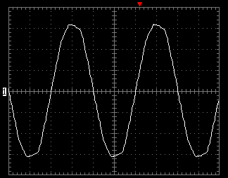
И в этом тесте замечания отсутствуют, синусоида никак не портится, меняется только ее амплитуда в зависимости от уровня напряжения.
Выводы
В случаях, когда отключения напряжения редки или пользователь не нуждается в бесперебойном питании своего оборудования, но при этом есть потребность в стабилизации напряжения, современные компактные стабилизаторы идеально подходят для решения проблемы. В отличие от своих древних прототипов, которые когда-то использовались для питания аналоговой электроники, нынешние модели бесшумны, не занимают много места и позволяют подключать достаточно большую нагрузку. (С учетом экономичности современной электроники даже к 600-ваттной модели в большинстве случаев можно подключить всю домашнюю аудио/видеотехнику.)
Рассмотренное в обзоре устройство является отличным примером качественной реализации.
Достоинства:
- качественная синусоида выходного напряжения
- соответствие (и даже превышение) заявленной максимальной мощности
- широкий диапазон входного напряжения
Недостатки:
- не обнаружено
Средняя текущая цена (количество предложений) в московской рознице: Н/Д(0)
More products and manuals for Surge protectors APC
| Models | Document Type |
|---|---|
|
SURGEARREST PMF3S-A |
Instruction Manual
20 pages |
|
SURGEARREST PMG4DS-A |
User Manual
4 pages |
|
SURGEARREST PML4S-A |
User Manual
4 pages |
|
P6V |
User Manual
2 pages |
|
P7GB |
User Manual
5 pages |
|
P11VT3 |
User Manual
2 pages |
|
P610 |
User Manual
1 pages |
|
BR800I |
User Manual
2 pages |
|
0217A7 |
User Manual
2 pages |
|
G5BLK |
Datasheet
42 pages |
|
BMG3-A |
Datasheet
2 pages |
|
PER7-LM |
Datasheet
2 pages |
|
PER8TVR |
Datasheet
1 pages |
|
P5BV-IT |
Datasheet
6 pages |
|
P1-IT |
Datasheet
6 pages |
|
SurgeArrest Essential |
Specifications
6 pages |
|
PM6-GR |
Specifications
6 pages |
|
P7T-LM |
Specifications
2 pages |
|
P1T-RS |
Specifications
6 pages |
|
PMF3XS-B |
Manual
24 pages |


Safety Messages
Safety Information
Adhere to all national and local electrical codes.
All wiring must be performed by a qualified electrician.Changes and modifications to this unit not expressly approved by APC by Schneider Electriccould void the warranty.
Product Decription
The Line-R automatically corrects brownouts (by boosting low voltage) and overvoltages (by stepping
down high voltage) from the power utility service to levels that are acceptable for computers, as well as other
sensitive equipment. APC by Schneider Electric Line-R provides a high degree of protection from linevoltage sags and swells, and has been designed for reliable, maintenance-free service.
Applications
Features
Installation
Specifications
Limited Warranty
CAUTION
NOTICE
Automatic Voltage Regulator
Models LS595-RS, LS1000-RS, and
LS1500-RS
EN 990-9731A03/2018
CAUTION indicates a hazardous situation which, if not avoided, could result in minor
or moderate injury.
NOTICE is used to address practices not related to physical injury.
Top Panel
Po wer LED
Illuminates when input voltage is
within normal range
AVR LE DAC O utlets
Illuminates when input voltage is
below or higher the rated Input
Voltage Range
These outlets supply power to
connected equipment when the Line—R
is connected to AC power
Rear Panel
Po wer SwitchAC P ower Co rd
Use this as the master power switch to
turn the Line—R and all connected
equipment on ( ) or off ( ).
Use this cable to connect the Line—R to
AC power.
Plug the Line-R into a Wall Outlet — Plug the Line-R into a wall socket. Connect your computer orother electronic equipment to any of the three outlets on the top panel of the Line-R. The Line-Rshould only be used in buildings that have proper grounding on a branch circuit protected by a fuseor circuit breaker.Connect Your Equipment — Plug equipment into the Line-R top-panel outlets and switch the equipment ON. The equipment will not be powered until the Line-R is switched on.Note: The total power consumption of all equipment plugged into the Line-R must not exceed theratings listed in the Specifications table below. Switch ON the Line-R — Press the back panel power switch to the on ( ) position. This switchmay be used as the master switch for the device and all equipment connected to it. Characteristics LS1000-RSLS595-RS LS1500-RS
Maximum Output Power Capacity
Nominal Output Voltage
Nominal Input Current
Acceptable Voltage Range Tolerance
500 W or 1000 VA300 W or 595 VA 750 W or 1500 VA
230V
1.65 A
2.71 A
4.07 A
Rated Input Voltage
Maximum Acceptable Input Voltage
Output Regulation
Response Time
Efficiency
Nominal Frequency
Number of Outlets
Operating Temperature
Relative Humidity
Weight
Dimensions
1.36 kg (2.9 lb)
1.6 kg (3.5 lb)
1.96 kg (4.3 lb)
184-284 VAC
230 Vac
284 Vac
10%
>95%
50 Hz
3
32 — 104 F (0 — 40 C)
0-90% Non-condensing
7.0 x 3.7 x 4.5 inches (180 x 95 x 119 mm)
6 ms
Surge Energy
148 Joules
© 2018 APC by Schneider Electric. APC, the APC logo and Line-R are owned by Schneider
Electric Industries S.A.S. or their affiliated companies. All other trademarks are property of
their respective owners.Note: The total power consumption of all equipment plugged into the Line-R must not exceed the
“Maximum Output Power Capacity” rating listed in the Specifications table.
The Line-R is designed for use with voltage sensitive equipment such as computers, monitors,printers, scanners, televisions, stereos or other AV equipment.Do not use with life sustaining equipment and any device with a power requirement exceeding the“Acceptable Voltage Range” rating listed in the Specifications table.Read the instructions carefully to become familiar with the equipment before attempting to install,operate, service or maintain the AVR (Automatic Voltage Regulator). The following special messagesmay appear throughout this manual or on the equipment to warn of potential hazards or to call attention to information that clarifies or simplifies a procedure.The addition of this symbol to a “Danger” or “Warning” safety label indicates that anelectrical hazard exists which will result in personal injury if the instructions are not followed.This is the safety alert symbol. It is used to alert you to potential personal injuryhazards. Obey all safety messages that follow this symbol to avoid possibleinjury or death.
APC by Schneider Electric IT Customer Support Worldwide
For country specific customer support, go to the APC by Schneider Electric Web site, www.apc.com.Schneider Electric IT (SEIT) warrants its products to be free from defects in materials and workmanship for a period of two years from the date of purchase. SE IT obligation under this warranty is limited to repairing or replacing, at its sole discretion, any such defective products. This warranty does not apply to battery wear from use, equipment that has been damaged by accident, negligence or misapplication or has been altered or modified in any way. SEIT standard procedure is to replace the original unit with a factory reconditioned unit. Customers who must have the original unit back due to the assignment of asset tags and set depreciation schedules must declare such a need at first contact with an SEIT Technical Support representative. SEIT will ship the replacement unit once the defective unit has been received by the repair department, or cross ship upon the receipt of a valid credit card number. The customer pays for shipping the unit to SEIT. SEIT pays ground freight transportation costs to ship the replacement unit to the customer. For full warranty information refer to www.apc.com.
TM
This product is intended for indoor use only.Do not block the air vents on the AVR. Allow adequate space for proper ventilation. Allow 1 inch (2.5 cm) minimum vent clearance.Do not operate this product in direct sunlight, in contact with fluids, or where there is excessive dust or humidity.
Displayed below is the user manual for Line R 600VA by APC which is a product in the Voltage Regulators category.
This manual has pages.
Safety Messages
Safety Information
Adhere to all national and local electrical codes.
All wiring must be performed by a qualified electrician.
Changes and modifications to this unit not expressly approved by APC by Schneider Electric
could void the warranty.
Product Decription
The Line-R automatically corrects brownouts (by boosting low voltage) and overvoltages (by stepping
down high voltage) from the power utility service to levels that are acceptable for computers, as well as other
sensitive equipment. APC by Schneider Electric Line-R provides a high degree of protection from line
voltage sags and swells, and has been designed for reliable, maintenance-free service.
Applications
Features
Installation
Specifications
Limited Warranty
CAUTION
NOTICE
Line-R
Automatic Voltage Regulator
Models LS595-RS, LS1000-RS, and
LS1500-RS
EN 990-9731A
03/2018
CAUTION indicates a hazardous situation which, if not avoided, could result in minor
or moderate injury.
NOTICE is used to address practices not related to physical injury.
Top Panel
Po wer LED Illuminates when input voltage is
within normal range
AVR LE D
AC O utlets
Illuminates when input voltage is
below or higher the rated Input
Voltage Range
These outlets supply power to
connected equipment when the Line—R
is connected to AC power
Rear Panel
Po wer Switch
AC P ower
Co rd
Use this as the master power switch to
turn the Line—R and all connected
equipment on ( ) or off ( ).
Use this cable to connect the Line—R to
AC power.
Plug the Line-R into a Wall Outlet — Plug the Line-R into a wall socket. Connect your computer or
other electronic equipment to any of the three outlets on the top panel of the Line-R. The Line-R
should only be used in buildings that have proper grounding on a branch circuit protected by a fuse
or circuit breaker.
Connect Your Equipment — Plug equipment into the Line-R top-panel outlets and switch the
equipment ON. The equipment will not be powered until the Line-R is switched on.
Note: The total power consumption of all equipment plugged into the Line-R must not exceed the
ratings listed in the Specifications table below.
Switch ON the Line-R — Press the back panel power switch to the on ( ) position. This switch
may be used as the master switch for the device and all equipment connected to it.
Characteristics LS1000-RSLS595-RS LS1500-RS
Maximum Output Power Capacity
Nominal Output Voltage
Nominal Input Current
Acceptable Voltage Range Tolerance
500 W or 1000 VA300 W or 595 VA 750 W or 1500 VA
230V
1.65 A 2.71 A 4.07 A
Rated Input Voltage
Maximum Acceptable Input Voltage
Output Regulation
Response Time
Efficiency
Nominal Frequency
Number of Outlets
Operating Temperature
Relative Humidity
Weight
Dimensions
1.36 kg (2.9 lb) 1.6 kg (3.5 lb) 1.96 kg (4.3 lb)
184-284 VAC
230 Vac
284 Vac
10%
>95%
50 Hz
3
32 — 104 F (0 — 40 C)
0-90% Non-condensing
7.0 x 3.7 x 4.5 inches (180 x 95 x 119 mm)
6 ms
Surge Energy 148 Joules
© 2018 APC by Schneider Electric. APC, the APC logo and Line-R are owned by Schneider
Electric Industries S.A.S. or their affiliated companies. All other trademarks are property of
their respective owners.
Note: The total power consumption of all equipment plugged into the Line-R must not exceed the
“Maximum Output Power Capacity” rating listed in the Specifications table.
The Line-R is designed for use with voltage sensitive equipment such as computers, monitors,
printers, scanners, televisions, stereos or other AV equipment.
Do not use with life sustaining equipment and any device with a power requirement exceeding the
“Acceptable Voltage Range” rating listed in the Specifications table.
Read the instructions carefully to become familiar with the equipment before attempting to install,
operate, service or maintain the AVR (Automatic Voltage Regulator). The following special messages
may appear throughout this manual or on the equipment to warn of potential hazards or to call
attention to information that clarifies or simplifies a procedure.
The addition of this symbol to a “Danger” or “Warning” safety label indicates that an
electrical hazard exists which will result in personal injury if the instructions are not
followed.
This is the safety alert symbol. It is used to alert you to potential personal injury
hazards. Obey all safety messages that follow this symbol to avoid possible
injury or death.
APC by Schneider Electric IT Customer Support Worldwide
For country specific customer support, go to the APC by Schneider Electric Web site, www.apc.com.
Schneider Electric IT (SEIT) warrants its products to be free from defects in materials and
workmanship for a period of two years from the date of purchase. SE IT obligation under this
warranty is limited to repairing or replacing, at its sole discretion, any such defective
products. This warranty does not apply to battery wear from use, equipment that has been
damaged by accident, negligence or misapplication or has been altered or modified in any
way. SEIT standard procedure is to replace the original unit with a factory reconditioned
unit. Customers who must have the original unit back due to the assignment of asset tags and
set depreciation schedules must declare such a need at first contact with an SEIT Technical
Support representative. SEIT will ship the replacement unit once the defective unit has been
received by the repair department, or cross ship upon the receipt of a valid credit card
number. The customer pays for shipping the unit to SEIT. SEIT pays ground freight
transportation costs to ship the replacement unit to the customer. For full warranty
information refer to www.apc.com.
TM
This product is intended for indoor use only.
Do not block the air vents on the AVR. Allow adequate space for proper ventilation.
Allow 1 inch (2.5 cm) minimum vent clearance.
Do not operate this product in direct sunlight, in contact with fluids, or where there
is excessive dust or humidity.
™
Line-R
Models 600 and 1250
User’s
Manual
Thank you!
Thank you for selecting this American Power Conversion Line-R™ brand
power conditioner. This power conditioner provides the highest degree of
protection from line voltage sags, swells, spikes, surges, and electrical noise. It
has been designed for many years of reliable, maintenance-free service.
Important safety instructions!
Please read this manual!
Veuillez lire ce manuel!
Bitte lesen Sie dieses Anleitungshandbuch!
¡Se ruega leer este manual de instrucciones!
This manual provides safety, installation, and operating instructions that will help you get the
fullest performance and service life that the Line-R has to offer.
Please save this manual! It includes important instructions for the safe use of this UPS, and
for obtaining factory service if necessary. Future service or storage issues may arise and require
reference to this manual.
Conserver ces instructions! Cette notice contient des instructions importantes concernant la
sécurité.
Radio frequency interference
Warning: Changes or modifications to this unit not expressly approved by the party responsible
for compliance could void the user’s authority to operate the equipment.
Note: This equipment has been tested and found to comply with the limits for a Class A digital
device, pursuant to Part 15 of the FCC Rules. These limits are designed to provide reasonable
protection against harmful interference when the equipment is operated in a commercial
environment. This equipment generates, uses, and can radiate radio frequency energy and, if
not installed and used in accordance with the instruction manual, may cause harmful interference
to radio communications. Operation of this equipment in a residential area is likely to cause
harmful interference in which case the user will be required to correct the interference at his
own expense.
This digital apparatus does not exceed the Class A limits for radio noise emissions from digital
apparatus set out in the Radio Interference Regulations of the Canadian Department of
Communications.
Le present appareil numerique n'emet pas de bruits radioelectriques depassant les limites
applicables aux appareils numeriques de la Class A prescrites dans le Reglement sur le brouillage
radioelectrique edicte par le ministere des Communications du Canada.
Hiermit wird bescheinigt, dass der Line-R 600, 1250 Stromversorgungs-Gerät in
Unereinstimmung mit den Bestimmungen der Vfg 1046/1984 funk-entstort ist. Der Deutschen
Bundespost wurde das Inverkehrbringen diese Gerates angezeigt und die Berechtigung zur
Uberprufung der Serie auf Einhaltung der Bestimmungen eingeraumt.
1.0 Introduction
1.1 Overview
This power conditioner is a high-performance, microprocessor-controlled
tap changing power conditioner which automatically corrects brownouts
and overvoltages from your power utility service to levels that are safe for
your computer and phone systems, and other sensitive equipment.
1.2 Voltage regulation
Chronically abnormal line voltage is often the result of adjustments made at
the power station to conserve energy or to compensate for low voltages in
other areas. Locally, the operation of heavy loads such as air conditioners,
office copiers, and laser printers may cause temporary voltage fluctuations.
This power conditioner uses reliable, fast-acting regulation circuitry to
protect your equipment from chronic brownouts (by boosting low voltage)
or overvoltage conditions (by stepping down high voltage), and provides
protection against short duration line voltage sags and swells.
1.3 Surge and noise suppression
The power conditioner features a multistage surge suppression design and
full-time electrical noise filters to suppress noise and surges caused by
lightning; nearby radio transmitters; and motor load switching in air
conditioners, elevators, and refrigerators to well below the tolerances of
even the most sensitive equipment.
Sag
Swell
Electrical noise
Surge
1
2.0 Safety !
Before starting your installation, please read the following safety
instructions!
■
The power conditioner is intended for indoor use only.
■ Operate the power conditioner in an area with adequate air flow, and an
atmosphere free of excessive dust and corrosive fumes. Do not block the
ventilation openings.
■ Do not place the power conditioner near heat-emitting appliances such
as radiators or stoves.
■ Avoid installing the power conditioner where there is water or excessive
humidity.
■ When using the power conditioner with an uninterruptible power
supply, connect the UPS to the power conditioner’s output.
2
3.0 Presentation
3.1 600 and 1250 VA power conditioners—front panel
Very High
High
Normal
Input voltage
level indicators
Low
Very Low
all versions
Surge Protection
Integrity
indicator
3.2 600 and 1250 VA power conditioners—rear panel
Power switch
Site Wiring Fault
indicator
Circuit breaker
NEMA 5-15R
receptacles
120 Vac version
Power switch
Circuit breaker
IEC 320
output couplers
IEC 320 inlet
230 Vac version
3
4.0 Installation
4.1 Receiving inspection
Remove the power conditioner from its shipping container and inspect it
for damage that may have occurred in transit. Notify the carrier and place
of purchase if any damage is found. The packing materials are made of
recyclable materials and should be saved for reuse or disposed of properly.
4.2 Placement
You may install the power conditioner in any protected environment. Make
sure you provide adequate air flow around the unit, in an atmosphere free
from excessive dust.
Note: Allow 1 inch (2.5 cm) minimum
clearance on all sides for proper
ventilation.
Do not operate the power conditioner is an environment where the ambient
temperature or humidity is outside the limits listed in the Specifications
section of this manual (see Sec. 6.6).
4
4.0 Installation
4.3 Connect the power conditioner to service and enable
■ 120 Vac version
Plug the power conditioner into a two-pole, three-wire grounding receptacle only. Avoid using extension cords and adapter plugs.
■ 230 Vac version
The 230 Vac version of the power conditioner is supplied with two output
IEC 320 cords. Swap a line cord from your equipment with one of the
output cords and plug in the power conditioner using the equipment cord.
The power conditioner’s input cord must be three-conductor, each 1.0
mm2, rated to 10 Amps.
If your equipment does not have a removable line cord, a rewireable plug
(included) may be installed on the line cord. Additional output cords and
adapter plugs are available from your dealer and from the factory.
5
4.0 Installation
4.4 Connect the load equipment
Plug your equipment into the power conditioner’s rear-panel receptacles. You
may switch the equipment on, but they will not be powered until you switch
on the power conditioner. Make sure the your total equipment load does not
exceed the power conditioner’s rated capacity (listed on the rear-panel).
4.5 Switch on the power conditioner
Switch on the power conditioner by pressing the rear-panel
Power switch to the on ( I ) position. This switch may be
used as a master on/off switch for all the equipment
connected to the power conditioner.
4.6 Check Site Wiring Fault indicator—120 version only
After you connect your equipment to the power conditioner and switch it on,
check the Site Wiring Fault indicator on the rear panel. It will light if the power
conditioner is plugged into an improperly wired outlet. Wiring faults detected
include missing ground, hot-neutral polarity reversal, and overloaded neutral
circuit.
Note: If the power conditioner indicates a site wiring fault, a qualified electrician
should be summoned to correct the building wiring.
4.7 Overloads/rear-panel circuit breaker
If you connect too much equipment to the power conditioner, it will
become overloaded and the circuit breaker will trip. When the breaker is
tripped, its button is extended. Eliminate the overload by disconnecting
noncritical equipment. Reset the circuit breaker by pressing the extended
button.
6
5.0 Operation
5.1 Front-panel indicators
5.1.1 Very High input voltage indicator
The Very High indicator lights when the power conditioner is regulating
input voltage which is approaching the upper limit of the conditioner’s
rated range.
5.1.2 High input voltage indicator
The High indicator lights when the power conditioner is regulating
input voltage which is above normal.
5.1.3 Normal input voltage indicator
The Normal indicator lights when the input voltage is normal.
5.1.4 Low input voltage indicator
The Low indicator lights when the power conditioner is regulating
input voltage which is below normal.
5.1.5 Very Low input voltage indicator
The Very Low indicator lights when the power conditioner is regulating
input voltage which is approaching the lower limit of the conditioner’s
rated range.
5.1.6 Surge Protection Integrity indicator
The Surge Protection OK indicator lights when the power conditioner
is on and operating normally. The indicator is off when the power
conditioner has disconnected itself from the input service because of a
sustained high-energy surge, or the unit is overloaded. If the indicator is
off, check the rear-panel circuit breaker, and reset it if necessary.
5.3 Audible alarm
The power conditioner will sound an audible alarm when it detects extreme input voltages that it cannot correct. Such high or low voltages will
cause output voltages outside the conditioner’s rated regulation band.
For 120 Vac models, the audible alarm sounds when the input voltage is
outside the range 85–150 Vac. For 230 Vac models, the audible alarm sounds
when the input voltage is outside 162–299 Vac.
7
6.0 Specifications
6.1 Input
version:
120 Vac
230 Vac
50 or 60 Hz
Frequency:
Model 600 maximum current:
8 Amp
3.5 Amp
Model 1250 maximum current:
15 Amp
7 Amp
6.2 Output
Model 600 maximum capacity:
600 W or 600 VA
Model 1250 maximum capacity:
1250 W or 1250 VA
6.3 Regulation
Input (Vac)
Output (Vac)
Regulation
88 to 150
106 to 127
ANSI C84.1-B
92 to 145
111 to 123
117 Vac ±5%
182 to 287
219 to 242
230 Vac ±5%
6.4 Surge & noise suppression
Surge energy capability:
320 Joules total (10/1000µs)
Normal mode ±6 kV IEEE 587 Cat. A let-through: <100 Vpeak
above input
Normal mode EMI/RFI attenuation:
35 to 55 dB
over 0.1–10.0 MHz
6.5 Physical
Size (H´W´D):
5.0 ´ 6.8 ´ 8.4 in.
(12.7 ´ 17.2 ´ 21.3 cm)
Model 600 weight:
11.0 lb (5.0 kg) 10.5 lb (4.8 kg)
Model 1250 weight:
15.5 lb (7.0 kg) 16.3 lb (7.4 kg)
6.6 Operating environment
Operating temperature:
Operating humidity:
Audible noise:
8
0 to 40 °C (32 to 104 °F)
0 to 95%, non-condensing
< 45 dBA at 3 ft (1 m)
Limited Warranty
American Power Conversion (APC) warrants its products to be free from defects in materials
and workmanship for a period of two years from the date of purchase. Its obligation under this
warranty is limited to repairing or replacing, at its own sole option, any such defective products.
To obtain service under warranty you must obtain a Returned Material Authorization (RMA)
number from APC or an APC service center. Products must be returned to APC or an APC
service center with transportation charges prepaid and must be accompanied by a brief
description of the problem encountered and proof of date and place of purchase. This warranty
does not apply to equipment which has been damaged by accident, negligence, or misapplication
or has been altered or modified in any way. This warranty applies only to the original purchaser
who must have properly registered the product within 10 days of purchase.
EXCEPT AS PROVIDED HEREIN, AMERICAN POWER CONVERSION MAKES NO
WARRANTIES, EXPRESS OR IMPLIED, INCLUDING WARRANTIES OF
MERCHANTABILITY AND FITNESS FOR A PARTICULAR PURPOSE. Some states do not
permit limitation or exclusion of implied warranties; therefore, the aforesaid limitation(s) or
exclusion(s) may not apply to the purchaser.
EXCEPT AS PROVIDED ABOVE, IN NO EVENT WILL APC BE LIABLE FOR DIRECT,
INDIRECT, SPECIAL, INCIDENTAL, OR CONSEQUENTIAL DAMAGES ARISING OUT OF
THE USE OF THIS PRODUCT, EVEN IF ADVISED OF THE POSSIBILITY OF SUCH DAMAGE.
Specifically, APC is not liable for any costs, such as lost profits or revenue, loss of equipment,
loss of use of equipment, loss of software, loss of data, costs of substitutes, claims by third
parties, or otherwise. This warranty gives you specific legal rights and you may also have other
rights which vary from state to state.
Life support policy
As a general policy, American Power Conversion (APC) does not recommend the use of any of
its products in life support applications where failure or malfunction of the APC product can be
reasonably expected to cause failure of the life support device or to significantly affect its safety
or effectiveness. APC does not recommend the use of any of its products in direct patient care.
APC will not knowingly sell its products for use in such applications unless it receives in writing
assurances satisfactory to APC that (a) the risks of injury or damage have been minimized, (b)
the customer assumes all such risks, and (c) the liability of American Power Conversion is
adequately protected under the circumstances.
Examples of devices considered to be life support devices are neonatal oxygen analyzers, nerve
stimulators (whether used for anesthesia, pain relief, or other purposes), autotransfusion devices,
blood pumps, defibrillators, arrhythmia detectors and alarms, pacemakers, hemodialysis
systems, peritoneal dialysis systems, neonatal ventilator incubators, ventilators for both adults
and infants, anesthesia ventilators, and infusion pumps as well as any other devices designated
as “critical” by the U.S. FDA.
Hospital grade wiring devices and leakage current may be ordered as options on many APC
UPS systems. APC does not claim that units with this modification are certified or listed as
Hospital Grade by APC or any other organization. Therefore these units do not meet the
requirements for use in direct patient care.
( PHONE
( PHONE
(800) 800-4272 in USA & Canada
(401) 789-5735 worldwide
(+33) 1.64.62.59.00 in Europe
(401) 789-5735 worldwide
* MAILING
* MAILING
American Power Conversion
132 Fairgrounds Road
P.O. Box 278
West Kingston, Rhode Island
02892 USA
American Power Conversion
4, rue Ste Claire Deville
Zac du Mandinet-Bâtiment Espace
Lognes
77447 Marne La Vallee Cédex 2
France
Please note: Before calling customer service, please have available your power
conditioner’s serial number (see label at the rear of the unit).
Serial number: ___________________
Entire contents copyright © 1993 American Power Conversion.
All rights reserved; reproduction in whole or in part without permission is prohibited.
Line-R is a trademark of APC. All other trademarks are the property of their respective owners.
990-0900-A
12/93