- Manuals
- Brands
- BTL Manuals
- Medical Equipment
- 6000 SWT TOPLINE
- User manual
-
Contents
-
Table of Contents
-
Bookmarks
Quick Links
BTL-6000 SWT
TOPLINE
USER’S MANUAL
v100AS08/01/2010EN
GENERAL CHARACTERISTICS OF THE DEVICE | PAGE 1 OF 38
Related Manuals for BTL 6000 SWT TOPLINE
Summary of Contents for BTL 6000 SWT TOPLINE
-
Page 1
BTL-6000 SWT TOPLINE USER’S MANUAL v100AS08/01/2010EN GENERAL CHARACTERISTICS OF THE DEVICE | PAGE 1 OF 38… -
Page 2
BEFORE YOU START Dear Customer, Thank you for purchasing BTL technology. All of us at BTL wish you every success with your system. We pride ourselves on being as responsive as possible to our customers’ needs. Your suggestions and comments are always welcome since we believe an ongoing relationship with our customers is critically important to our future product line. -
Page 3: Table Of Contents
Possible side Effects of Shockwave Treatment……………………7 Indications for Shockwave Treatment ……………………..8 Contra-indications for Shockwave Treatment……………………8 INSTRUCTIONS FOR OPERATION……………………….9 The Front Panel of the BTL-6000 SWT Topline ……………………9 Applicator for BTL-6000 SWT Topline ……………………..9 The Rear Panel of the BTL-6000 SWT Topline…………………….10 Assembly and Set-Up………………………….11 Basic Displays and Operating of the Device ……………………12…
-
Page 4
2.11.3.8 Operation Mode …………………………23 2.11.3.9 Touch Panel Calibration……………………….23 2.11.3.10 User Options…………………………..23 2.11.3.11 Setting of HW Key …………………………23 2.11.3.12 Unit Information …………………………23 2.11.3.13 Unlock Code …………………………..23 2.11.3.14 Service Functions …………………………24 2.11.4 Specific Settings …………………………..24 2.11.4.1 Applicator Button Mode……………………….24 2.11.4.2 Applicator Kit Replacement Wizard …………………….24 LIST OF STANDARD AND OPTIONAL ACCESSORIES ………………..25 MAINTENANCE AND SAFETY INSTRUCTIONS……………………26 4.1.1… -
Page 5: General Characteristics Of The Device
A time-saving feature of the BTL-6000 SWT Topline is the predefined programs stored in the memory of the main unit. Based on detailed research and practical use of the device, the well-organized predefined programs will provide recommendations for the treatment of various conditions.
-
Page 6: Shockwave And Its Character
Several types of generators have been developed for shockwave therapy, each producing shockwaves with varied characteristics. Each type of generation method induces shockwaves with different time progressions and spatial arrangements. The BTL-6000 SWT Topline uses the ballistic principle of shockwave generation. 1.3.1 BALLISTIC PRINCIPLE OF SHOCKWAVE GENERATION A pressure wave is formed via a projectile by using accelerated compressed air.
-
Page 7: Biological Effects Of Shockwave Treatment
1.4 BIOLOGICAL EFFECTS OF SHOCKWAVE TREATMENT The effects of the shockwaves mainly occur at sites where there is a change in impedance, such as the bone-soft tissue interface. There is an improvement in the regeneration and repair of tissues in the following areas and the achievement of the following effects: •…
-
Page 8: Indications For Shockwave Treatment
1.7 INDICATIONS FOR SHOCKWAVE TREATMENT • Plantar Fasciitis • Achillodynia/Achillobursitis • Inflammations and calcification of shoulder joint tendons. • Pain in the groin area. • Epicondylitis (Tennis and Golf Elbow) • Apex Patellae Syndrome and Tibial Stress Syndrome. • Pain in the hip area and/or the iliotibial tract. •…
-
Page 9: Instructions For Operation
2 INSTRUCTIONS FOR OPERATION THE FRONT PANEL OF THE BTL-6000 SWT TOPLINE 10 3 10 4 10 5 10 2 touch screen select knob (to select individual parameters) enter key esc key start / stop key (to start and stop therapy) ON/OFF switch (back lit, in blue, when the control unit is ‘’on’’…
-
Page 10: The Rear Panel Of The Btl-6000 Swt Topline
THE REAR PANEL OF THE BTL-6000 SWT TOPLINE connector for shockwave applicator control unit mains fuse connector for power cable power on/off switch vessel for collecting condensed water type label – contains type of the device, manufacturer and safety and warning signs…
-
Page 11: Assembly And Set-Up
Do not place the device close to appliances producing strong electromagnetic, electric or magnetic field (diathermy, X-rays, etc.), otherwise it could be undesirably influenced. In the event of any questions, please contact an authorized service of BTL devices. Procedure: First connect the device in mains by means of the supplied power supply adapter, which you will connect to the connector on the rear panel of the device and to a 100 V or 240 V mains socket.
-
Page 12: Basic Displays And Operating Of The Device
BASIC DISPLAYS AND OPERATING OF THE DEVICE 2.5.1 INITIAL SCREEN AND TYPES OF TABS The initial screen after the switch-on of the device contains the tab displaying information about the connected accessories. Examples of information shown on the tabs: Indicates that no accessories are connected Indicates that the applicator is connected and shockwave therapy can be applied.
-
Page 13: Numeric Keypad
2.5.3 NUMERIC KEYPAD In addition to setting the numerical values with the select knob on all the screens, the ”numeric keypad» can be use for the faster setting of values. This is the icon for the opening of the numeric keyboard window: Press the numeric keypad button to display the window with the numeric keypad for the parameter with the “pressed”…
-
Page 14: Setting Therapy Parameters Manually (User Setup) Via The ‘Man’ Button
2.6.3 SETTING THERAPY PARAMETERS MANUALLY (USER SETUP) VIA THE ‘MAN’ BUTTON The therapy parameters screen for the user (manual) setting will be displayed by pressing the man button. All specifications of the therapy can be set and possibly saved as a user program or a diagnosis. Pressing of individual buttons will open an individual menu and pop-up boxes for the settings.
-
Page 15: Setting Therapy Intensity
The endless therapy option allows for an infinite number of shocks, that can be applied from the start of the therapy. The end of therapy is not limited to the number of shocks. 2.6.5 SETTING THERAPY INTENSITY The intensity (power) of the shockwave therapy can be set on the therapy parameters screen, even during the course of therapy.
-
Page 16: Therapy Parameters Screen — Ergonomic, Standard And Expert Mode
2.6.6 THERAPY PARAMETERS SCREEN – ERGONOMIC, STANDARD AND EXPERT MODE This screen always appears before the start of therapy when the diag or prog buttons are pressed (see Diagram of the therapy setting process). If only the most important therapy parameters are shown, then the ergonomic operation mode was selected.
-
Page 17: Running Therapy Screen
2.7.2 RUNNING THERAPY SCREEN Name of selected therapy / program and the set parameters Set frequency Number of applied shocks Set number of shocks Set intensity Number of remaining shocks Icon and name of connected accessories Time of applied therapy Symbolic description of generated output 2.7.3…
-
Page 18
Examples of how to hold the shockwave applicator These examples illustrate the application of shockwaves in different areas and several of ways of holding the applicator. Painful shoulder Trigger-points Tibial Edge Syndrome Calcar Calcanei (Plantar Fasciitis) Epicondylitis Achillodynia Patellar Tendinopathy (Jumper’s Knee) Trigger points INSTRUCTIONS FOR OPERATION | PAGE 18 OF 38… -
Page 19: Saving Therapy
SAVING THERAPY A particular operation can selected after pressing the “save” button. Depending on which operation is selected, a chart with the appropriate data will be shown. An example of the procedure is displayed on the following screens. It is always possible to save the therapy after setting its parameters, for example from the screen of therapy parameters – see the chapter Therapy parameters screen.
-
Page 20: Clients
2.10.1 CLIENTS This feature allows the entering, editing and deleting of information about clients. A particular therapy can be assigned to each client. 2.10.2 USER DIAGNOSES/PROGRAMS This feature makes it possible to start the user therapies, to adjust their parameters, names and descriptions, to delete them and to sort them by using the buttons and choices shown on the screen.
-
Page 21: Information
The memory-chip contains a lot of information and reading it takes from 30 seconds to 2 minutes. The “installation of accessories” function serves for faster functioning of the unit. After the installation, under normal operation of the device only the serial number of the accessory is read from the accessory’s memory and the other information is read from the device’s memory.
-
Page 22: Unit Settings
2.11.3 UNIT SETTINGS This submenu offers the options of setting and displaying these parameters: • Password setting • Sound setting • Screen saver and auto switch-off • Colour setting • Setting of display contrast • Date and time setting • Language setting •…
-
Page 23: Setting Of Display Contrast
2.11.3.5 Setting of Display Contrast Allows the setting of the optimum contrast (readability) of the display by turning the select knob. Since the contrast of the screen depends on various factors, such as the temperature of the room, there is a faster and direct way of setting the screen contrast.
-
Page 24: Service Functions
2.11.3.14 Service Functions • repair of files Checks the file storage system of the device, the system of saved information. It will repair possible errors, delete empty files, etc. We recommend using this feature in the event of a lack of memory space, if the device rejects saving any data, or if you are in doubt that some data may have been lost.
-
Page 25: List Of Standard And Optional Accessories
1x spare fuse T6.3A,L,250V • 1x User’s Manual on CD Optional accessories: • transport case for the BTL-6000 SWT Topline • additional shockwave applicator with focusing shock transmitter • gel 300 ml LIST OF STANDARD AND OPTIONAL ACCESSORIES | PAGE 25 OF 38…
-
Page 26: Maintenance And Safety Instructions
Exterior cleaning of the device: Use a soft cloth slightly moistened with water or with a 2% detergent solution to clean the exterior of the BTL-6000 SWT Topline device and its parts. Never use cleaning agents containing alcohol, ammonia, benzine, thinners, etc. Never use abrasive cleaning materials which will scratch the device’s surfaces.
-
Page 27: Shock Transmitter Replacement Procedure
4.1.1 SHOCK TRANSMITTER REPLACEMENT PROCEDURE The shock transmitter can be replaced as necessary. Three shock transmitters are included as part of the BTL-6000 SWT Topline standard accessories: • 1x replaceable multi-focus shock transmitter (Ø 15mm) • 1x replaceable multi-focus shock transmitter (Ø 9mm) •…
-
Page 28: Procedure Of Worn-Out Tube And Projectile Replacement
If the applicator stops working correctly after some amount of time, then it is possible to change the worn-out parts of the tube and projectile by using the spare parts kit included in the BTL-6000 SWT Topline package. Do not use damaged applicators! There is a risk of injury to the operating staff or the client.
-
Page 29
Use the key to unscrew the screw cap of the cartridge. See the pictures below. Remove the worn-out part from the cartridge from the applicator Remove the plastic cover from a new replacement part. MAINTENANCE AND SAFETY INSTRUCTIONS | PAGE 29 OF 38… -
Page 30
Insert the shock transmitter back into the applicator, including both of its O-rings. 10. Put the shock transmitter screw cap back in place and screw it on tightly by hand. 11. Reconnect the applicator to the BTL-6000 SWT Topline device. MAINTENANCE AND SAFETY INSTRUCTIONS | PAGE 30 OF 38… -
Page 31: General Safety Precautions
If the source of the concern can be determine after a thorough study of the user’s manual, then contact an authorized BTL service department immediately. If the device is not used in accordance with this manual or if it is used when the device exhibits functional differences from those stated in this manual, then BTL is not responsible for any damage to or caused by the device.
-
Page 32: Used Symbols
BTL’s sole obligations under this warranty are as set forth herein. In no event shall BTL be liable for any lost revenue or profits, direct, indirect, special, incidental or consequential damages of any kind.
-
Page 33: Technical Parameters
5 TECHNICAL PARAMETERS Identification of the device B T L — 6 0 0 0 S W T T o p l i n e Operating conditions Ambient temperature + 10 ° C to + 40 ° C Relative humidity 30 % to 75 % Atmospheric pressure 700 hPa to 1060 hPa…
-
Page 34
Technical parameters of the Switching Power Supply Adapter BTL-4000 SWT 150W Design Weight – device only 780 g approx. Dimensions (w x h x d) 142 x 76 x 43,7 mm Covering grade according to EN 60 529 IP20 Class according to IEC 60601-1… -
Page 35: Emc Information
Directive and declaration of manufacturer – Electromagnetic Emission BTL-6000 SWT Topline is suitable for use in the specified electromagnetic environment. The purchaser or user of BTL-6000 SWT Topline should assure that it is used in an electromagnetic environment as described below…
-
Page 36
Directive and declaration of manufacturer – Electromagnetic immunity BTL-6000 SWT Topline is suitable for use in the specified electromagnetic environment. The purchaser or user of BTL-6000 SWT Topline should assure that it is used in an electromagnetic environment as described below. -
Page 37: Applicable Standards
5.2 APPLICABLE STANDARDS Name IEC, MDD EN, ISO, Medical electrical equipment – IEC 60601-1:2005 EN ISO 60601-1:2007 Part 1: General requirements for basic safety and essential performance Medical electrical equipment Part 1: General requirements for safety 1.Collateral standard: Safety IEC 60601-1-1:2000 EN ISO 60601-1-1:2001 requirements for medical electrical systems Medical electrical equipment –…
-
Page 38: Manufacturer
Except as required by applicable law, no warranties of any kind, either expressed or implied, are made for the accuracy, reliability or contents of this document. BTL Industries Limited reserves the right to revise or withdraw this document at any time without prior notice.
- Manuals
- Brands
- BTL Manuals
- Medical Equipment
- 6000 SWT TOPLINE
- User manual
-
Contents
-
Table of Contents
-
Bookmarks
Quick Links
BTL-6000 SWT
TOPLINE
USER’S MANUAL
v100AS08/01/2010EN
GENERAL CHARACTERISTICS OF THE DEVICE | PAGE 1 OF 38
Related Manuals for BTL 6000 SWT TOPLINE
Summary of Contents for BTL 6000 SWT TOPLINE
- Page 1
BTL-6000 SWT TOPLINE USER’S MANUAL v100AS08/01/2010EN GENERAL CHARACTERISTICS OF THE DEVICE | PAGE 1 OF 38… - Page 2
BEFORE YOU START Dear Customer, Thank you for purchasing BTL technology. All of us at BTL wish you every success with your system. We pride ourselves on being as responsive as possible to our customers’ needs. Your suggestions and comments are always welcome since we believe an ongoing relationship with our customers is critically important to our future product line. -
Page 3: Table Of Contents
Possible side Effects of Shockwave Treatment……………………7 Indications for Shockwave Treatment ……………………..8 Contra-indications for Shockwave Treatment……………………8 INSTRUCTIONS FOR OPERATION……………………….9 The Front Panel of the BTL-6000 SWT Topline ……………………9 Applicator for BTL-6000 SWT Topline ……………………..9 The Rear Panel of the BTL-6000 SWT Topline…………………….10 Assembly and Set-Up………………………….11 Basic Displays and Operating of the Device ……………………12…
- Page 4
2.11.3.8 Operation Mode …………………………23 2.11.3.9 Touch Panel Calibration……………………….23 2.11.3.10 User Options…………………………..23 2.11.3.11 Setting of HW Key …………………………23 2.11.3.12 Unit Information …………………………23 2.11.3.13 Unlock Code …………………………..23 2.11.3.14 Service Functions …………………………24 2.11.4 Specific Settings …………………………..24 2.11.4.1 Applicator Button Mode……………………….24 2.11.4.2 Applicator Kit Replacement Wizard …………………….24 LIST OF STANDARD AND OPTIONAL ACCESSORIES ………………..25 MAINTENANCE AND SAFETY INSTRUCTIONS……………………26 4.1.1… -
Page 5: General Characteristics Of The Device
A time-saving feature of the BTL-6000 SWT Topline is the predefined programs stored in the memory of the main unit. Based on detailed research and practical use of the device, the well-organized predefined programs will provide recommendations for the treatment of various conditions.
-
Page 6: Shockwave And Its Character
Several types of generators have been developed for shockwave therapy, each producing shockwaves with varied characteristics. Each type of generation method induces shockwaves with different time progressions and spatial arrangements. The BTL-6000 SWT Topline uses the ballistic principle of shockwave generation. 1.3.1 BALLISTIC PRINCIPLE OF SHOCKWAVE GENERATION A pressure wave is formed via a projectile by using accelerated compressed air.
-
Page 7: Biological Effects Of Shockwave Treatment
1.4 BIOLOGICAL EFFECTS OF SHOCKWAVE TREATMENT The effects of the shockwaves mainly occur at sites where there is a change in impedance, such as the bone-soft tissue interface. There is an improvement in the regeneration and repair of tissues in the following areas and the achievement of the following effects: •…
-
Page 8: Indications For Shockwave Treatment
1.7 INDICATIONS FOR SHOCKWAVE TREATMENT • Plantar Fasciitis • Achillodynia/Achillobursitis • Inflammations and calcification of shoulder joint tendons. • Pain in the groin area. • Epicondylitis (Tennis and Golf Elbow) • Apex Patellae Syndrome and Tibial Stress Syndrome. • Pain in the hip area and/or the iliotibial tract. •…
-
Page 9: Instructions For Operation
2 INSTRUCTIONS FOR OPERATION THE FRONT PANEL OF THE BTL-6000 SWT TOPLINE 10 3 10 4 10 5 10 2 touch screen select knob (to select individual parameters) enter key esc key start / stop key (to start and stop therapy) ON/OFF switch (back lit, in blue, when the control unit is ‘’on’’…
-
Page 10: The Rear Panel Of The Btl-6000 Swt Topline
THE REAR PANEL OF THE BTL-6000 SWT TOPLINE connector for shockwave applicator control unit mains fuse connector for power cable power on/off switch vessel for collecting condensed water type label – contains type of the device, manufacturer and safety and warning signs…
-
Page 11: Assembly And Set-Up
Do not place the device close to appliances producing strong electromagnetic, electric or magnetic field (diathermy, X-rays, etc.), otherwise it could be undesirably influenced. In the event of any questions, please contact an authorized service of BTL devices. Procedure: First connect the device in mains by means of the supplied power supply adapter, which you will connect to the connector on the rear panel of the device and to a 100 V or 240 V mains socket.
-
Page 12: Basic Displays And Operating Of The Device
BASIC DISPLAYS AND OPERATING OF THE DEVICE 2.5.1 INITIAL SCREEN AND TYPES OF TABS The initial screen after the switch-on of the device contains the tab displaying information about the connected accessories. Examples of information shown on the tabs: Indicates that no accessories are connected Indicates that the applicator is connected and shockwave therapy can be applied.
-
Page 13: Numeric Keypad
2.5.3 NUMERIC KEYPAD In addition to setting the numerical values with the select knob on all the screens, the ”numeric keypad» can be use for the faster setting of values. This is the icon for the opening of the numeric keyboard window: Press the numeric keypad button to display the window with the numeric keypad for the parameter with the “pressed”…
-
Page 14: Setting Therapy Parameters Manually (User Setup) Via The ‘Man’ Button
2.6.3 SETTING THERAPY PARAMETERS MANUALLY (USER SETUP) VIA THE ‘MAN’ BUTTON The therapy parameters screen for the user (manual) setting will be displayed by pressing the man button. All specifications of the therapy can be set and possibly saved as a user program or a diagnosis. Pressing of individual buttons will open an individual menu and pop-up boxes for the settings.
-
Page 15: Setting Therapy Intensity
The endless therapy option allows for an infinite number of shocks, that can be applied from the start of the therapy. The end of therapy is not limited to the number of shocks. 2.6.5 SETTING THERAPY INTENSITY The intensity (power) of the shockwave therapy can be set on the therapy parameters screen, even during the course of therapy.
-
Page 16: Therapy Parameters Screen — Ergonomic, Standard And Expert Mode
2.6.6 THERAPY PARAMETERS SCREEN – ERGONOMIC, STANDARD AND EXPERT MODE This screen always appears before the start of therapy when the diag or prog buttons are pressed (see Diagram of the therapy setting process). If only the most important therapy parameters are shown, then the ergonomic operation mode was selected.
-
Page 17: Running Therapy Screen
2.7.2 RUNNING THERAPY SCREEN Name of selected therapy / program and the set parameters Set frequency Number of applied shocks Set number of shocks Set intensity Number of remaining shocks Icon and name of connected accessories Time of applied therapy Symbolic description of generated output 2.7.3…
- Page 18
Examples of how to hold the shockwave applicator These examples illustrate the application of shockwaves in different areas and several of ways of holding the applicator. Painful shoulder Trigger-points Tibial Edge Syndrome Calcar Calcanei (Plantar Fasciitis) Epicondylitis Achillodynia Patellar Tendinopathy (Jumper’s Knee) Trigger points INSTRUCTIONS FOR OPERATION | PAGE 18 OF 38… -
Page 19: Saving Therapy
SAVING THERAPY A particular operation can selected after pressing the “save” button. Depending on which operation is selected, a chart with the appropriate data will be shown. An example of the procedure is displayed on the following screens. It is always possible to save the therapy after setting its parameters, for example from the screen of therapy parameters – see the chapter Therapy parameters screen.
-
Page 20: Clients
2.10.1 CLIENTS This feature allows the entering, editing and deleting of information about clients. A particular therapy can be assigned to each client. 2.10.2 USER DIAGNOSES/PROGRAMS This feature makes it possible to start the user therapies, to adjust their parameters, names and descriptions, to delete them and to sort them by using the buttons and choices shown on the screen.
-
Page 21: Information
The memory-chip contains a lot of information and reading it takes from 30 seconds to 2 minutes. The “installation of accessories” function serves for faster functioning of the unit. After the installation, under normal operation of the device only the serial number of the accessory is read from the accessory’s memory and the other information is read from the device’s memory.
-
Page 22: Unit Settings
2.11.3 UNIT SETTINGS This submenu offers the options of setting and displaying these parameters: • Password setting • Sound setting • Screen saver and auto switch-off • Colour setting • Setting of display contrast • Date and time setting • Language setting •…
-
Page 23: Setting Of Display Contrast
2.11.3.5 Setting of Display Contrast Allows the setting of the optimum contrast (readability) of the display by turning the select knob. Since the contrast of the screen depends on various factors, such as the temperature of the room, there is a faster and direct way of setting the screen contrast.
-
Page 24: Service Functions
2.11.3.14 Service Functions • repair of files Checks the file storage system of the device, the system of saved information. It will repair possible errors, delete empty files, etc. We recommend using this feature in the event of a lack of memory space, if the device rejects saving any data, or if you are in doubt that some data may have been lost.
-
Page 25: List Of Standard And Optional Accessories
1x spare fuse T6.3A,L,250V • 1x User’s Manual on CD Optional accessories: • transport case for the BTL-6000 SWT Topline • additional shockwave applicator with focusing shock transmitter • gel 300 ml LIST OF STANDARD AND OPTIONAL ACCESSORIES | PAGE 25 OF 38…
-
Page 26: Maintenance And Safety Instructions
Exterior cleaning of the device: Use a soft cloth slightly moistened with water or with a 2% detergent solution to clean the exterior of the BTL-6000 SWT Topline device and its parts. Never use cleaning agents containing alcohol, ammonia, benzine, thinners, etc. Never use abrasive cleaning materials which will scratch the device’s surfaces.
-
Page 27: Shock Transmitter Replacement Procedure
4.1.1 SHOCK TRANSMITTER REPLACEMENT PROCEDURE The shock transmitter can be replaced as necessary. Three shock transmitters are included as part of the BTL-6000 SWT Topline standard accessories: • 1x replaceable multi-focus shock transmitter (Ø 15mm) • 1x replaceable multi-focus shock transmitter (Ø 9mm) •…
-
Page 28: Procedure Of Worn-Out Tube And Projectile Replacement
If the applicator stops working correctly after some amount of time, then it is possible to change the worn-out parts of the tube and projectile by using the spare parts kit included in the BTL-6000 SWT Topline package. Do not use damaged applicators! There is a risk of injury to the operating staff or the client.
- Page 29
Use the key to unscrew the screw cap of the cartridge. See the pictures below. Remove the worn-out part from the cartridge from the applicator Remove the plastic cover from a new replacement part. MAINTENANCE AND SAFETY INSTRUCTIONS | PAGE 29 OF 38… - Page 30
Insert the shock transmitter back into the applicator, including both of its O-rings. 10. Put the shock transmitter screw cap back in place and screw it on tightly by hand. 11. Reconnect the applicator to the BTL-6000 SWT Topline device. MAINTENANCE AND SAFETY INSTRUCTIONS | PAGE 30 OF 38… -
Page 31: General Safety Precautions
If the source of the concern can be determine after a thorough study of the user’s manual, then contact an authorized BTL service department immediately. If the device is not used in accordance with this manual or if it is used when the device exhibits functional differences from those stated in this manual, then BTL is not responsible for any damage to or caused by the device.
-
Page 32: Used Symbols
BTL’s sole obligations under this warranty are as set forth herein. In no event shall BTL be liable for any lost revenue or profits, direct, indirect, special, incidental or consequential damages of any kind.
-
Page 33: Technical Parameters
5 TECHNICAL PARAMETERS Identification of the device B T L — 6 0 0 0 S W T T o p l i n e Operating conditions Ambient temperature + 10 ° C to + 40 ° C Relative humidity 30 % to 75 % Atmospheric pressure 700 hPa to 1060 hPa…
- Page 34
Technical parameters of the Switching Power Supply Adapter BTL-4000 SWT 150W Design Weight – device only 780 g approx. Dimensions (w x h x d) 142 x 76 x 43,7 mm Covering grade according to EN 60 529 IP20 Class according to IEC 60601-1… -
Page 35: Emc Information
Directive and declaration of manufacturer – Electromagnetic Emission BTL-6000 SWT Topline is suitable for use in the specified electromagnetic environment. The purchaser or user of BTL-6000 SWT Topline should assure that it is used in an electromagnetic environment as described below…
- Page 36
Directive and declaration of manufacturer – Electromagnetic immunity BTL-6000 SWT Topline is suitable for use in the specified electromagnetic environment. The purchaser or user of BTL-6000 SWT Topline should assure that it is used in an electromagnetic environment as described below. -
Page 37: Applicable Standards
5.2 APPLICABLE STANDARDS Name IEC, MDD EN, ISO, Medical electrical equipment – IEC 60601-1:2005 EN ISO 60601-1:2007 Part 1: General requirements for basic safety and essential performance Medical electrical equipment Part 1: General requirements for safety 1.Collateral standard: Safety IEC 60601-1-1:2000 EN ISO 60601-1-1:2001 requirements for medical electrical systems Medical electrical equipment –…
-
Page 38: Manufacturer
Except as required by applicable law, no warranties of any kind, either expressed or implied, are made for the accuracy, reliability or contents of this document. BTL Industries Limited reserves the right to revise or withdraw this document at any time without prior notice.
 Loading…

BTL-6000 SWT TOPLINE
USER’S MANUAL
v100AS08/01/2010EN

BEFORE YOU START
Dear Customer,
Thank you for purchasing BTL technology. All of us at BTL wish you every success with your system. We pride ourselves on being as responsive as possible to our customers’ needs. Your suggestions and comments are always welcome since we believe an ongoing relationship with our customers is critically important to our future product line.
While we would like you to start using your new equipment right away, we encourage a thorough reading of this manual in order to fully understand the operational features of the system.
Please visit our corporate website at http://www.btlnet.com for the latest information on BTL products and services.
Again, thank you for being a BTL customer.
BTL Industries, Ltd.
PAGE 2 OF 38

CONTENTS
|
1 GENERAL CHARACTERISTICS OF THE DEVICE………………………………………………………………………………………………… |
5 |
|||
|
1.1 |
BTL–6000 SWT Topline System Series……………………………………………………………………………………………………………… |
5 |
||
|
1.2 |
Shockwave and Its Character…………………………………………………………………………………………………………………………… |
6 |
||
|
1.3 |
Shockwave Generation……………………………………………………………………………………………………………………………………. |
6 |
||
|
1.3.1 |
Ballistic Principle of Shockwave Generation ……………………………………………………………………………………………………… |
6 |
||
|
1.4 |
Biological Effects of Shockwave Treatment ………………………………………………………………………………………………………… |
7 |
||
|
1.5 |
Advantages of Shockwave Treatment ……………………………………………………………………………………………………………….. |
7 |
||
|
1.6 |
Possible side Effects of Shockwave Treatment……………………………………………………………………………………………………. |
7 |
||
|
1.7 |
Indications for Shockwave Treatment ………………………………………………………………………………………………………………… |
8 |
||
|
1.8 |
Contra-indications for Shockwave Treatment………………………………………………………………………………………………………. |
8 |
||
|
2 INSTRUCTIONS FOR OPERATION…………………………………………………………………………………………………………………….. |
9 |
|||
|
2.1 |
The Front Panel of the BTL-6000 SWT Topline …………………………………………………………………………………………………… |
9 |
||
|
2.2 |
Applicator for BTL-6000 SWT Topline ……………………………………………………………………………………………………………….. |
9 |
||
|
2.3 |
The Rear Panel of the BTL-6000 SWT Topline………………………………………………………………………………………………….. |
10 |
||
|
2.4 |
Assembly and Set-Up……………………………………………………………………………………………………………………………………. |
11 |
||
|
2.5 |
Basic Displays and Operating of the Device ……………………………………………………………………………………………………… |
12 |
||
|
2.5.1 |
Initial Screen and Types of Tabs …………………………………………………………………………………………………………………… |
12 |
||
|
2.5.2 |
Touch Screen…………………………………………………………………………………………………………………………………………….. |
12 |
||
|
2.5.3 |
Numeric Keypad ………………………………………………………………………………………………………………………………………… |
13 |
||
|
2.6 |
Setting of Therapy ………………………………………………………………………………………………………………………………………… |
13 |
||
|
2.6.1 |
Setting Therapy Parameters Via the ‘diag’ Button ……………………………………………………………………………………………. |
13 |
||
|
2.6.2 |
Setting Therapy Parameters Via the ‘prog’ Button ……………………………………………………………………………………………. |
13 |
||
|
2.6.3 |
Setting Therapy Parameters Manually (User Setup) Via the ‘man’ Button …………………………………………………………… |
14 |
||
|
2.6.4 |
Setting the Number of Shocks………………………………………………………………………………………………………………………. |
14 |
||
|
2.6.5 |
Setting Therapy Intensity……………………………………………………………………………………………………………………………… |
15 |
||
|
2.6.6 |
Therapy Parameters Screen – Ergonomic, Standard and Expert Mode……………………………………………………………….. |
16 |
||
|
2.7 |
Course of Therapy………………………………………………………………………………………………………………………………………… |
16 |
||
|
2.7.1 |
Start, Interruption and End of Therapy……………………………………………………………………………………………………………. |
16 |
||
|
2.7.2 |
Running Therapy Screen …………………………………………………………………………………………………………………………….. |
17 |
||
|
2.7.3 |
End of Therapy / Generation of Shocks………………………………………………………………………………………………………….. |
17 |
||
|
2.8 |
Application of Shockwaves …………………………………………………………………………………………………………………………….. |
17 |
||
|
2.9 |
Saving Therapy ……………………………………………………………………………………………………………………………………………. |
19 |
||
|
2.10 |
User Settings: The ‘user’ Button ……………………………………………………………………………………………………………………… |
19 |
||
|
2.10.1 |
Clients………………………………………………………………………………………………………………………………………………………. |
20 |
||
|
2.10.2 |
User Diagnoses/Programs …………………………………………………………………………………………………………………………… |
20 |
||
|
2.10.3 |
Recent Therapies……………………………………………………………………………………………………………………………………….. |
20 |
||
|
2.11 |
Unit Settings: The ‘menu’ Button …………………………………………………………………………………………………………………….. |
20 |
||
|
2.11.1 |
Accessories……………………………………………………………………………………………………………………………………………….. |
20 |
||
|
2.11.1.1 |
Installation ………………………………………………………………………………………………………………………………………….. |
20 |
||
|
2.11.1.2 |
Information………………………………………………………………………………………………………………………………………….. |
21 |
||
|
2.11.2 |
Encyclopaedia……………………………………………………………………………………………………………………………………………. |
21 |
||
|
2.11.3 |
Unit Settings………………………………………………………………………………………………………………………………………………. |
22 |
||
|
2.11.3.1 |
Password Setting…………………………………………………………………………………………………………………………………. |
22 |
||
|
2.11.3.2 |
Sound Setting ……………………………………………………………………………………………………………………………………… |
22 |
||
|
2.11.3.3 |
Screen Saver and Auto Switch-Off………………………………………………………………………………………………………….. |
22 |
||
|
2.11.3.4 |
Colour Setting……………………………………………………………………………………………………………………………………… |
22 |
||
|
2.11.3.5 |
Setting of Display Contrast…………………………………………………………………………………………………………………….. |
23 |
||
|
2.11.3.6 |
Date and Time Setting ………………………………………………………………………………………………………………………….. |
23 |
||
|
2.11.3.7 |
Language Setting…………………………………………………………………………………………………………………………………. |
23 |
PAGE 3 OF 38

|
2.11.3.8 |
Operation Mode …………………………………………………………………………………………………………………………………… |
23 |
|
|
2.11.3.9 |
Touch Panel Calibration………………………………………………………………………………………………………………………… |
23 |
|
|
2.11.3.10 |
User Options……………………………………………………………………………………………………………………………………….. |
23 |
|
|
2.11.3.11 |
Setting of HW Key ……………………………………………………………………………………………………………………………….. |
23 |
|
|
2.11.3.12 |
Unit Information …………………………………………………………………………………………………………………………………… |
23 |
|
|
2.11.3.13 |
Unlock Code ……………………………………………………………………………………………………………………………………….. |
23 |
|
|
2.11.3.14 |
Service Functions ………………………………………………………………………………………………………………………………… |
24 |
|
|
2.11.4 Specific Settings ………………………………………………………………………………………………………………………………………… |
24 |
||
|
2.11.4.1 |
Applicator Button Mode…………………………………………………………………………………………………………………………. |
24 |
|
|
2.11.4.2 |
Applicator Kit Replacement Wizard …………………………………………………………………………………………………………. |
24 |
|
|
3 LIST OF STANDARD AND OPTIONAL ACCESSORIES ………………………………………………………………………………………. |
25 |
||
|
4 MAINTENANCE AND SAFETY INSTRUCTIONS…………………………………………………………………………………………………. |
26 |
||
|
4.1.1 Shock Transmitter Replacement Procedure ……………………………………………………………………………………………………. |
27 |
||
|
4.1.2 Procedure of Worn-out Tube and Projectile Replacement …………………………………………………………………………………. |
28 |
||
|
4.2 |
General Safety Precautions……………………………………………………………………………………………………………………………. |
31 |
|
|
4.3 |
Used Symbols ……………………………………………………………………………………………………………………………………………… |
32 |
|
|
4.4 |
Warranty……………………………………………………………………………………………………………………………………………………… |
32 |
|
|
5 |
TECHNICAL PARAMETERS ……………………………………………………………………………………………………………………………. |
33 |
|
|
5.1 |
EMC Information ………………………………………………………………………………………………………………………………………….. |
35 |
|
|
5.2 |
Applicable Standards…………………………………………………………………………………………………………………………………….. |
37 |
|
|
5.3 |
Manufacturer ……………………………………………………………………………………………………………………………………………….. |
38 |
PAGE 4 OF 38

1 GENERAL CHARACTERISTICS OF THE DEVICE
The BTL-6000 SWT Topline is a state-of-the-art device allowing the application of therapy using non-invasive shockwaves. Shockwaves are one of the most effective ways to treat pain associated with the musculoskeletal system. Musculoskeletal pain is currently the second-leading cause of absences in the workplace.
The device is equipped with a color touch screen on the main unit which considerably simplifies its use. The touch screen is equipped with a stylus (touch-pen) for easy operation of the device. The horizontally orientation of the device allows the information on the screen to be seen clearly from different servicing positions. Additionally, the brightness of the screen can be set to match the lighting in the room of the office or the health-care center. The on-screen information will guide the user step- by-step through the entire therapy process. The therapeutic parameters are easily set using the touch screen buttons and knobs/keys on the device.
Therapy is easily and efficiently started by simply selecting a diagnosis from an alphabetized list of treatment protocols or by selecting a therapy program. The treatment parameters can be manually set by the simple use of the touch screen buttons. Throughout the course of a therapy session, the device will keep the user informed about the therapeutic method in use, the type of treatment, the total number of shocks to be applied, the number of shocks applied and remaining, the frequency being used, the intensity and other necessary data.
A time-saving feature of the BTL-6000 SWT Topline is the predefined programs stored in the memory of the main unit. Based on detailed research and practical use of the device, the well-organized predefined programs will provide recommendations for the treatment of various conditions.
The BTL-6000 SWT Topline allows the entering of client names and other relevant information into the internal memory of the device and to link their data with the predefined programs or with the user’s own. When a client has a return visit, simply call up their name and begin the pre-set therapy.
We also carry a specially-designed cart for the BTL-6000 SWT Topline which is sold separately. The design allows convenient movement and use of the device. Four stable castors ensure smooth and easy movement of the device in the office or the health-care center.
For the latest information on BTL products and services, please visit our corporate website at http://www.btlnet.com.
1.1BTL–6000 SWT TOPLINE SYSTEM SERIES
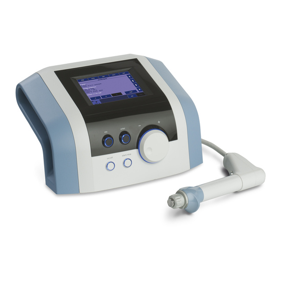
The device consists of two parts: the main unit and the applicator
Main Unit: BTL-6000 SWT Topline which contains the main microcomputer and software for controlling the entire system,in also includes the user encyclopaedia and the therapy guide.
Applicator – ergonomical applicator simplifies the „course of» the therapy, following the instructionsof the main unit.
The BTL-6000 SWT Topline is a state-of-the-art device allowing the application of therapy using non-invasive shockwaves. Shockwaves are one of the most effective ways to treat pain associated with the musculoskeletal system. Musculoskeletal pain is currently the second-leading cause of absences in the workplace.
The device consists of two parts:
∙Main Unit – contains the main microcomputer and software for controlling the entire system
∙Applicator – this ergonomically designed applicator will simplify the course of therapy
GENERAL CHARACTERISTICS OF THE DEVICE | PAGE 5 OF 38

1.2 SHOCKWAVE AND ITS CHARACTER
A shockwave is defined as a wave with a rapid increase of pressure within a very short time and then having a gradual decrease of pressure with a small negative pressure phase.
Shockwaves are aimed at the affected areas that are the source of chronic pain. The influence of the shockwaves causes to the dissolution of calcium deposits and leads to better vascularization. The after-effect is relief from the pain.
Outside of the client’s body (extra-corporeally), a pressure pulse of high amplitude is generated and its energy is concentrated on the target area. The pressure pulse travels through a liquid medium gel into the client’s body and penetrates soft tissue without major energy loss.
The pressure course of the shockwave in real-time in expressively different from the pressure course of the harmonic sound wave. Shockwaves can be compared to ultrasonic waves which are particularly characterized by a pressure jump change, a higher amplitude and non-periodicity.
In the shockwave, the positive amplitude is generally much larger than the negative amplitude. The frequency rate of the shockwaves is usually low (in Hz units) and the eventual cavitation (the disturbance of material consistency and the development of cavities) will relax. Consequently, there is no threat of energy absorption in the cavitations as is the case with continuous ultrasound.
A substantial part of the shockwave energy penetrates into the liquid (of the organism) with a great positive pressure pulse. Its diffusion is only limited by the actual tissue absorption and eventual reflections on acoustic non-homogeneities.
A shockwave is defined as a pressure pulse with these characteristics:
∙High positive pressure amplitude: 10 to 1000 MPa = 100 to 1000 Bar (100x atmospheric pressure)
∙Low negative pressure amplitude: 1 to 10 MPa
∙Short time duration: 1 µs to 20 µs
∙Rapid pressure increase: < 100 ns
∙Broad frequency spectrum: 1 Hz to 1 MHz
For therapeutic applications, these values are lower, especially the maximum pressure amplitude. The maximum pressure amplitude is about 15 MPa, the pulse length is 10 to 20 µs, and the frequency of the applied shockwave is 1 to 15Hz. The treatment is generally carried out without local anaesthesia and lasts about 15 to 30 minutes. During the first week after treatment, the client should avoid all physical activities that could excessively strain the treated area.
1.3 SHOCKWAVE GENERATION
Several types of generators have been developed for shockwave therapy, each producing shockwaves with varied characteristics. Each type of generation method induces shockwaves with different time progressions and spatial arrangements.
The BTL-6000 SWT Topline uses the ballistic principle of shockwave generation.
1.3.1BALLISTIC PRINCIPLE OF SHOCKWAVE GENERATION
A pressure wave is formed via a projectile by using accelerated compressed air. The compressed air is generated by an electronically-controlled ballistic-pressure compressor. Using elastic impact, the kinetic energy of the projectile is transferred into the probe of the applicator and then into the client’s body. Consequently, during the treatment, the end of the applicator must be in direct -contact with the skin and subcutaneous tissue.
GENERAL CHARACTERISTICS OF THE DEVICE | PAGE 6 OF 38

1.4 BIOLOGICAL EFFECTS OF SHOCKWAVE TREATMENT
The effects of the shockwaves mainly occur at sites where there is a change in impedance, such as the bone-soft tissue interface.
There is an improvement in the regeneration and repair of tissues in the following areas and the achievement of the following effects:
∙Cellular: Increase in cell membrane transmittance by improving ionic channels activity, stimulation of cell division, stimulation of cellular cytokines production.
∙Reproduction of vessels in the area of tendons and muscles: Improvement of blood circulation and MTB, increase in concentration of growth factor beta 1, chemotactic and mitogenic effect on osteoblasts.
∙Effect on nitrogen oxide system: Bone healing and re-modelling.
∙Improvement of micro-circulation and metabolism
∙Dissolution of calcified fibroblasts
∙Supports the production of collagen
∙Reduction in tissue tension
∙Analgesic effect:
o Destruction of afferent nerves and nerve receptors.
o CNS stimulants, sensed as pain, are also inflammation transmitter substances. o Regression of pain caused by local ischemia.
oGate control theory of pain.
1.5ADVANTAGES OF SHOCKWAVE TREATMENT
∙By the targeted application of the shockwaves, stress to the surrounding tissues is quite insignificant.
∙The body is not burdened by pharmaceuticals, except the short-term effect of local anaesthesia, if used.
∙The possibility of preventing the necessity of surgical intervention and its relevant hazards.
∙Thanks to ambulatory treatment, work absences are reduced to a minimum. Additionally, training routine absences for sport athletes is likewise reduced.
∙For some indications, such as Tennis Elbow, there is really no other effective treatment.
1.6POSSIBLE SIDE EFFECTS OF SHOCKWAVE TREATMENT
∙Erythema or swelling can temporarily occur in the treated area.
∙Loss of bodily sensation or itching can temporarily occur in the treated area
∙Hematoma
∙Petechiae
∙Skin damage after previous corticoid therapy
∙Shockwave application can cause undesirable heart activity
GENERAL CHARACTERISTICS OF THE DEVICE | PAGE 7 OF 38

1.7INDICATIONS FOR SHOCKWAVE TREATMENT
∙Plantar Fasciitis
∙Achillodynia/Achillobursitis
∙Inflammations and calcification of shoulder joint tendons.
∙Pain in the groin area.
∙Epicondylitis (Tennis and Golf Elbow)
∙Apex Patellae Syndrome and Tibial Stress Syndrome.
∙Pain in the hip area and/or the iliotibial tract.
∙Jumper’s Knee (Patellar Tendinitis)
∙Pain in the hamstring insertions.
∙Pain on the palmar side of the wrist.
∙Exostoses of small hand joints from Grade 1 Arthrosis.
∙Acupuncture
∙Pain trigger-points or painful points in muscles.
1.8CONTRA-INDICATIONS FOR SHOCKWAVE TREATMENT
∙Application to certain tissues: The eyes and the surrounding area, the myocardium, the spinal cord, the gonads, the kidneys and the liver
∙Blood disorders, coagulation problems or the use of anticoagulants
∙Blood thinning medications (Warfarinization)
∙Polypus in the area of treatment
∙Pregnancy
∙Thrombosis
∙Tumor diseases
∙Polyneuropathy
∙Acute inflammation
∙Growing cartilage in children
∙Therapy using corticoids
∙Inapplicable on areas of the body and organs with possible gas content
∙Inapplicable on areas in proximity to large nerve bundles, blood vessels, the spinal cord and the head
GENERAL CHARACTERISTICS OF THE DEVICE | PAGE 8 OF 38
2INSTRUCTIONS FOR OPERATION
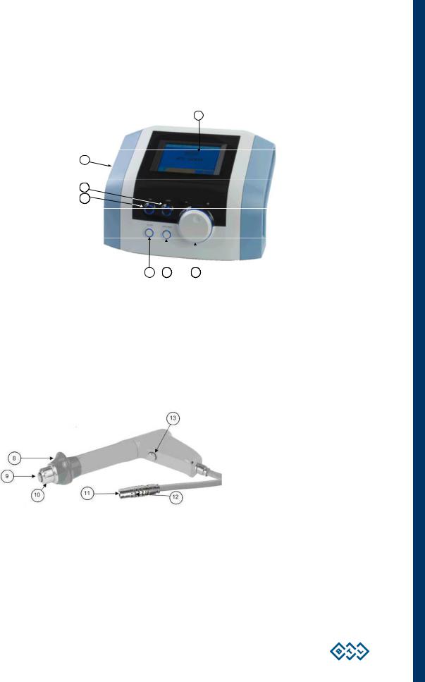
2.1THE FRONT PANEL OF THE BTL-6000 SWT TOPLINE
1
7
103
104
1.touch screen
2.select knob (to select individual parameters)
3.enter key
4.esc key
5.start / stop key (to start and stop therapy)
6.ON/OFF switch (back lit, in blue, when the control unit is ‘’on’’ )
7.USB port in the space of the device’s grip for use only in compliance with IEC 60950-1
The USB port serves only for service purposes such as upload of firmware; it is not designed for therapy use!
2.2APPLICATOR FOR BTL-6000 SWT TOPLINE
8.hand rest of the applicator
9.shock transmitter of the applicator
10.shock transmitter screw cap of the applicator
11.connector of the applicator
12.guide mark of the connector
13.applicator button: to start therapy
INSTRUCTIONS FOR OPERATION | PAGE 9 OF 38
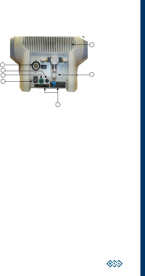
2.3THE REAR PANEL OF THE BTL-6000 SWT TOPLINE
14.connector for shockwave applicator
15.control unit mains fuse
16.connector for power cable
17.power on/off switch
18.vessel for collecting condensed water
19.type label – contains type of the device, manufacturer and safety and warning signs
20.venting grid
INSTRUCTIONS FOR OPERATION | PAGE 10 OF 38
![]()
2.4ASSEMBLY AND SET-UP
Inspect the box for damage and report any damage to the transport carrier and the distributor. Do not proceed with assembly and set-up if the box is damaged. Keep the original box and packaging to ensure safe future transport of the device.
When bringing the device from a cold environment into a warm one, do not plug it into the power source until the device has had to equilibrate to room temperature (Minimum 2 hours).
Unpack the device and place it on a stable horizontal surface which is suitable for its weight. Always position the device out of direct sunlight. During operation, the control unit gets warm, so it must not be positioned near direct heat sources. The device is self-cooled by forced air circulation. The cooling vents are located on the rear panel and on the bottom. Do not cover or block these vents. Allow a minimum of 4 inches (10cm) clearance behind the rear panel. Do not place the device on a soft surface (such as a towel) which may obstruct air flow to the bottom cooling vents. Do not put any heat-producing devices or any objects containing water or other liquids on the device. Do not put any heat-producing devices or objects containing water or other liquid on the device. Do not place the device close to appliances producing strong electromagnetic, electric or magnetic field (diathermy, X-rays, etc.), otherwise it could be undesirably influenced.
In the event of any questions, please contact an authorized service of BTL devices.
Procedure:
1.First connect the device in mains by means of the supplied power supply adapter, which you will connect to the connector on the rear panel of the device and to a 100 V or 240 V mains socket. The device detects the voltage automatically.
Plug the device directly into the mains socket. Do not use any multi-connection extension cables or two-socket adaptors.
2.Connect the applicator to the connector on the rear panel as follows:
Turn the applicator so that the red dot on its end is in straight line with the red dot on the output connector and only then plug the connector in.
When disconnecting the connector take the indented part of the applicator connector’s end in your fingers and pull slowly towards you to disconnect the connector carefully.
CAUTION! DO NOT TURN THE ENTIRE CONNECTED CONNECTOR BY FORCE, OTHERWISE THERE IS A RISK OF DAMAGE TO THE DEVICE!
The device detects the accessory, specifies its type and displays it on the screen in the appropriate tab. If you connect an improper accessory by mistake, the display shows a message with a help where to connect the given accessory.
3.Then switch on the power on/off switch on the rear panel of the device.
4.Press the on/off switch located on the front panel of the device.
Note:
After switching the device on, the device will run a self-diagnostic of its internal circuits and its functions for about 10 to 15 seconds. If any fault is detected, the screen will display a warning message. If necessary; the control unit will lock itself into a “secure” mode. If this situation occurs, please contact your authorized BTL distributor.
INSTRUCTIONS FOR OPERATION | PAGE 11 OF 38
2.5BASIC DISPLAYS AND OPERATING OF THE DEVICE
2.5.1INITIAL SCREEN AND TYPES OF TABS
The initial screen after the switch-on of the device contains the tab displaying information about the connected accessories.
Examples of information shown on the tabs:
Indicates that no accessories are connected
Indicates that the applicator is connected and shockwave therapy can be applied.
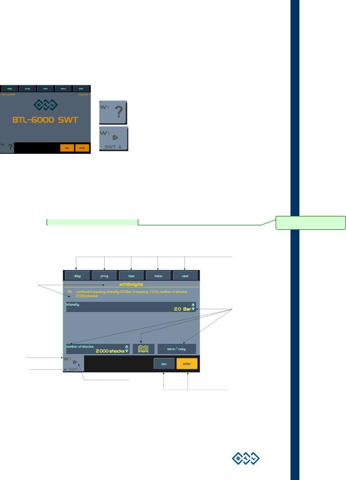
2.5.2TOUCH SCREEN
The touch screen can display several graphic elements. Some are only for informative purposes but others can be pressed and activated. These basic elements include:
∙3D buttons which can be pressed to change the indicated values
∙Informative text
∙Channels tabs to switch between the channels and selection
The items on the touch screen can be pressed by a finger or by using a special pointer with a soft tip, so — called touchpen, which is included in the accessories of the device. The touch screen must not come in contact with any sharp objects, ball pens etc.
3D buttons of the menu
Information
3D buttons
Channel marking: W = shockwave
1 = No. of generator
|
Information about connected accessories |
Buttons with the same function as |
|
esc and enter on the control panel |
INSTRUCTIONS FOR OPERATION | PAGE 12 OF 38
Comment [andy1]: Neni dostupné této verzi
CONTENTS
1
GENERAL CHARACTERISTICS OF THE DEVICE…………………………………………………………………………………………………5
1.1
BTL-6000 SWT Topline System Series………………………………………………………………………………………………………………5
1.2
Shockwave and Its Character ……………………………………………………………………………………………………………………………6
1.3
Shockwave Generation…………………………………………………………………………………………………………………………………….6
1.3.1
1.4
1.5
Advantages of Shockwave Treatment ………………………………………………………………………………………………………………..7
1.6
1.7
Indications for Shockwave Treatment …………………………………………………………………………………………………………………8
1.8
2
INSTRUCTIONS FOR OPERATION……………………………………………………………………………………………………………………..9
2.1
2.2
Applicator for BTL-6000 SWT Topline ………………………………………………………………………………………………………………..9
2.3
2.4
Assembly and Set-Up…………………………………………………………………………………………………………………………………….11
2.5
2.5.1
Initial Screen and Types of Tabs ……………………………………………………………………………………………………………………12
2.5.2
Touch Screen……………………………………………………………………………………………………………………………………………..12
2.5.3
Numeric Keypad …………………………………………………………………………………………………………………………………………13
2.6
Setting of Therapy …………………………………………………………………………………………………………………………………………13
2.6.1
2.6.2
2.6.3
2.6.4
Setting the Number of Shocks……………………………………………………………………………………………………………………….14
2.6.5
Setting Therapy Intensity………………………………………………………………………………………………………………………………15
2.6.6
2.7
Course of Therapy…………………………………………………………………………………………………………………………………………16
2.7.1
Start, Interruption and End of Therapy…………………………………………………………………………………………………………….16
2.7.2
Running Therapy Screen ……………………………………………………………………………………………………………………………..17
2.7.3
End of Therapy / Generation of Shocks…………………………………………………………………………………………………………..17
2.8
Application of Shockwaves ……………………………………………………………………………………………………………………………..17
2.9
Saving Therapy …………………………………………………………………………………………………………………………………………….19
2.10 User Settings: The ‘user’ Button ………………………………………………………………………………………………………………………19
2.10.1 Clients……………………………………………………………………………………………………………………………………………………….20
2.10.2 User Diagnoses/Programs ……………………………………………………………………………………………………………………………20
2.10.3 Recent Therapies………………………………………………………………………………………………………………………………………..20
2.11 Unit Settings: The ‘menu’ Button ……………………………………………………………………………………………………………………..20
2.11.1 Accessories………………………………………………………………………………………………………………………………………………..20
2.11.1.1
Installation …………………………………………………………………………………………………………………………………………..20
2.11.1.2
Information…………………………………………………………………………………………………………………………………………..21
2.11.2 Encyclopaedia…………………………………………………………………………………………………………………………………………….21
2.11.3 Unit Settings……………………………………………………………………………………………………………………………………………….22
2.11.3.1
Password Setting………………………………………………………………………………………………………………………………….22
2.11.3.2
Sound Setting ………………………………………………………………………………………………………………………………………22
2.11.3.3
Screen Saver and Auto Switch-Off…………………………………………………………………………………………………………..22
2.11.3.4
Colour Setting ………………………………………………………………………………………………………………………………………22
2.11.3.5
Setting of Display Contrast……………………………………………………………………………………………………………………..23
2.11.3.6
Date and Time Setting …………………………………………………………………………………………………………………………..23
2.11.3.7
Language Setting………………………………………………………………………………………………………………………………….23
PAGE 3 OF 38
BEFORE YOU START
Dear Customer,
Thank you for purchasing BTL technology. All of us at BTL wish
you every success with your system. We pride ourselves on being
as responsive as possible to our customers’ needs. Your
suggestions and comments are always welcome since we believe
an ongoing relationship with our customers is critically important to
our future product line.
While we would like you to start using your new equipment right
away, we encourage a thorough reading of this manual in order to
fully understand the operational features of the system.
Please visit our corporate website at http://www.btlnet.com for the
latest information on BTL products and services.
Again, thank you for being a BTL customer.
BTL Industries, Ltd.
PAGE 2 OF 38
BTL-6000 SWT TOPLINE
USER’S MANUAL
v100AS08/01/2010EN
BEFORE YOU START
Dear Customer,
Thank you for purchasing BTL technology. All of us at BTL wish you every success with your system. We pride ourselves on being as responsive as possible to our customers’ needs. Your suggestions and comments are always welcome since we believe an ongoing relationship with our customers is critically important to our future product line.
While we would like you to start using your new equipment right away, we encourage a thorough reading of this manual in order to fully understand the operational features of the system.
Please visit our corporate website at http://www.btlnet.com for the latest information on BTL products and services.
Again, thank you for being a BTL customer.
BTL Industries, Ltd.
PAGE 2 OF 38
CONTENTS
|
1 GENERAL CHARACTERISTICS OF THE DEVICE………………………………………………………………………………………………… |
5 |
|||
|
1.1 |
BTL–6000 SWT Topline System Series……………………………………………………………………………………………………………… |
5 |
||
|
1.2 |
Shockwave and Its Character…………………………………………………………………………………………………………………………… |
6 |
||
|
1.3 |
Shockwave Generation……………………………………………………………………………………………………………………………………. |
6 |
||
|
1.3.1 |
Ballistic Principle of Shockwave Generation ……………………………………………………………………………………………………… |
6 |
||
|
1.4 |
Biological Effects of Shockwave Treatment ………………………………………………………………………………………………………… |
7 |
||
|
1.5 |
Advantages of Shockwave Treatment ……………………………………………………………………………………………………………….. |
7 |
||
|
1.6 |
Possible side Effects of Shockwave Treatment……………………………………………………………………………………………………. |
7 |
||
|
1.7 |
Indications for Shockwave Treatment ………………………………………………………………………………………………………………… |
8 |
||
|
1.8 |
Contra-indications for Shockwave Treatment………………………………………………………………………………………………………. |
8 |
||
|
2 INSTRUCTIONS FOR OPERATION…………………………………………………………………………………………………………………….. |
9 |
|||
|
2.1 |
The Front Panel of the BTL-6000 SWT Topline …………………………………………………………………………………………………… |
9 |
||
|
2.2 |
Applicator for BTL-6000 SWT Topline ……………………………………………………………………………………………………………….. |
9 |
||
|
2.3 |
The Rear Panel of the BTL-6000 SWT Topline………………………………………………………………………………………………….. |
10 |
||
|
2.4 |
Assembly and Set-Up……………………………………………………………………………………………………………………………………. |
11 |
||
|
2.5 |
Basic Displays and Operating of the Device ……………………………………………………………………………………………………… |
12 |
||
|
2.5.1 |
Initial Screen and Types of Tabs …………………………………………………………………………………………………………………… |
12 |
||
|
2.5.2 |
Touch Screen…………………………………………………………………………………………………………………………………………….. |
12 |
||
|
2.5.3 |
Numeric Keypad ………………………………………………………………………………………………………………………………………… |
13 |
||
|
2.6 |
Setting of Therapy ………………………………………………………………………………………………………………………………………… |
13 |
||
|
2.6.1 |
Setting Therapy Parameters Via the ‘diag’ Button ……………………………………………………………………………………………. |
13 |
||
|
2.6.2 |
Setting Therapy Parameters Via the ‘prog’ Button ……………………………………………………………………………………………. |
13 |
||
|
2.6.3 |
Setting Therapy Parameters Manually (User Setup) Via the ‘man’ Button …………………………………………………………… |
14 |
||
|
2.6.4 |
Setting the Number of Shocks………………………………………………………………………………………………………………………. |
14 |
||
|
2.6.5 |
Setting Therapy Intensity……………………………………………………………………………………………………………………………… |
15 |
||
|
2.6.6 |
Therapy Parameters Screen – Ergonomic, Standard and Expert Mode……………………………………………………………….. |
16 |
||
|
2.7 |
Course of Therapy………………………………………………………………………………………………………………………………………… |
16 |
||
|
2.7.1 |
Start, Interruption and End of Therapy……………………………………………………………………………………………………………. |
16 |
||
|
2.7.2 |
Running Therapy Screen …………………………………………………………………………………………………………………………….. |
17 |
||
|
2.7.3 |
End of Therapy / Generation of Shocks………………………………………………………………………………………………………….. |
17 |
||
|
2.8 |
Application of Shockwaves …………………………………………………………………………………………………………………………….. |
17 |
||
|
2.9 |
Saving Therapy ……………………………………………………………………………………………………………………………………………. |
19 |
||
|
2.10 |
User Settings: The ‘user’ Button ……………………………………………………………………………………………………………………… |
19 |
||
|
2.10.1 |
Clients………………………………………………………………………………………………………………………………………………………. |
20 |
||
|
2.10.2 |
User Diagnoses/Programs …………………………………………………………………………………………………………………………… |
20 |
||
|
2.10.3 |
Recent Therapies……………………………………………………………………………………………………………………………………….. |
20 |
||
|
2.11 |
Unit Settings: The ‘menu’ Button …………………………………………………………………………………………………………………….. |
20 |
||
|
2.11.1 |
Accessories……………………………………………………………………………………………………………………………………………….. |
20 |
||
|
2.11.1.1 |
Installation ………………………………………………………………………………………………………………………………………….. |
20 |
||
|
2.11.1.2 |
Information………………………………………………………………………………………………………………………………………….. |
21 |
||
|
2.11.2 |
Encyclopaedia……………………………………………………………………………………………………………………………………………. |
21 |
||
|
2.11.3 |
Unit Settings………………………………………………………………………………………………………………………………………………. |
22 |
||
|
2.11.3.1 |
Password Setting…………………………………………………………………………………………………………………………………. |
22 |
||
|
2.11.3.2 |
Sound Setting ……………………………………………………………………………………………………………………………………… |
22 |
||
|
2.11.3.3 |
Screen Saver and Auto Switch-Off………………………………………………………………………………………………………….. |
22 |
||
|
2.11.3.4 |
Colour Setting……………………………………………………………………………………………………………………………………… |
22 |
||
|
2.11.3.5 |
Setting of Display Contrast…………………………………………………………………………………………………………………….. |
23 |
||
|
2.11.3.6 |
Date and Time Setting ………………………………………………………………………………………………………………………….. |
23 |
||
|
2.11.3.7 |
Language Setting…………………………………………………………………………………………………………………………………. |
23 |
PAGE 3 OF 38
|
2.11.3.8 |
Operation Mode …………………………………………………………………………………………………………………………………… |
23 |
|
|
2.11.3.9 |
Touch Panel Calibration………………………………………………………………………………………………………………………… |
23 |
|
|
2.11.3.10 |
User Options……………………………………………………………………………………………………………………………………….. |
23 |
|
|
2.11.3.11 |
Setting of HW Key ……………………………………………………………………………………………………………………………….. |
23 |
|
|
2.11.3.12 |
Unit Information …………………………………………………………………………………………………………………………………… |
23 |
|
|
2.11.3.13 |
Unlock Code ……………………………………………………………………………………………………………………………………….. |
23 |
|
|
2.11.3.14 |
Service Functions ………………………………………………………………………………………………………………………………… |
24 |
|
|
2.11.4 Specific Settings ………………………………………………………………………………………………………………………………………… |
24 |
||
|
2.11.4.1 |
Applicator Button Mode…………………………………………………………………………………………………………………………. |
24 |
|
|
2.11.4.2 |
Applicator Kit Replacement Wizard …………………………………………………………………………………………………………. |
24 |
|
|
3 LIST OF STANDARD AND OPTIONAL ACCESSORIES ………………………………………………………………………………………. |
25 |
||
|
4 MAINTENANCE AND SAFETY INSTRUCTIONS…………………………………………………………………………………………………. |
26 |
||
|
4.1.1 Shock Transmitter Replacement Procedure ……………………………………………………………………………………………………. |
27 |
||
|
4.1.2 Procedure of Worn-out Tube and Projectile Replacement …………………………………………………………………………………. |
28 |
||
|
4.2 |
General Safety Precautions……………………………………………………………………………………………………………………………. |
31 |
|
|
4.3 |
Used Symbols ……………………………………………………………………………………………………………………………………………… |
32 |
|
|
4.4 |
Warranty……………………………………………………………………………………………………………………………………………………… |
32 |
|
|
5 |
TECHNICAL PARAMETERS ……………………………………………………………………………………………………………………………. |
33 |
|
|
5.1 |
EMC Information ………………………………………………………………………………………………………………………………………….. |
35 |
|
|
5.2 |
Applicable Standards…………………………………………………………………………………………………………………………………….. |
37 |
|
|
5.3 |
Manufacturer ……………………………………………………………………………………………………………………………………………….. |
38 |
PAGE 4 OF 38
1 GENERAL CHARACTERISTICS OF THE DEVICE
The BTL-6000 SWT Topline is a state-of-the-art device allowing the application of therapy using non-invasive shockwaves. Shockwaves are one of the most effective ways to treat pain associated with the musculoskeletal system. Musculoskeletal pain is currently the second-leading cause of absences in the workplace.
The device is equipped with a color touch screen on the main unit which considerably simplifies its use. The touch screen is equipped with a stylus (touch-pen) for easy operation of the device. The horizontally orientation of the device allows the information on the screen to be seen clearly from different servicing positions. Additionally, the brightness of the screen can be set to match the lighting in the room of the office or the health-care center. The on-screen information will guide the user step- by-step through the entire therapy process. The therapeutic parameters are easily set using the touch screen buttons and knobs/keys on the device.
Therapy is easily and efficiently started by simply selecting a diagnosis from an alphabetized list of treatment protocols or by selecting a therapy program. The treatment parameters can be manually set by the simple use of the touch screen buttons. Throughout the course of a therapy session, the device will keep the user informed about the therapeutic method in use, the type of treatment, the total number of shocks to be applied, the number of shocks applied and remaining, the frequency being used, the intensity and other necessary data.
A time-saving feature of the BTL-6000 SWT Topline is the predefined programs stored in the memory of the main unit. Based on detailed research and practical use of the device, the well-organized predefined programs will provide recommendations for the treatment of various conditions.
The BTL-6000 SWT Topline allows the entering of client names and other relevant information into the internal memory of the device and to link their data with the predefined programs or with the user’s own. When a client has a return visit, simply call up their name and begin the pre-set therapy.
We also carry a specially-designed cart for the BTL-6000 SWT Topline which is sold separately. The design allows convenient movement and use of the device. Four stable castors ensure smooth and easy movement of the device in the office or the health-care center.
For the latest information on BTL products and services, please visit our corporate website at http://www.btlnet.com.
1.1BTL–6000 SWT TOPLINE SYSTEM SERIES
The device consists of two parts: the main unit and the applicator
Main Unit: BTL-6000 SWT Topline which contains the main microcomputer and software for controlling the entire system,in also includes the user encyclopaedia and the therapy guide.
Applicator – ergonomical applicator simplifies the „course of» the therapy, following the instructionsof the main unit.
The BTL-6000 SWT Topline is a state-of-the-art device allowing the application of therapy using non-invasive shockwaves. Shockwaves are one of the most effective ways to treat pain associated with the musculoskeletal system. Musculoskeletal pain is currently the second-leading cause of absences in the workplace.
The device consists of two parts:
∙Main Unit – contains the main microcomputer and software for controlling the entire system
∙Applicator – this ergonomically designed applicator will simplify the course of therapy
GENERAL CHARACTERISTICS OF THE DEVICE | PAGE 5 OF 38
1.2 SHOCKWAVE AND ITS CHARACTER
A shockwave is defined as a wave with a rapid increase of pressure within a very short time and then having a gradual decrease of pressure with a small negative pressure phase.
Shockwaves are aimed at the affected areas that are the source of chronic pain. The influence of the shockwaves causes to the dissolution of calcium deposits and leads to better vascularization. The after-effect is relief from the pain.
Outside of the client’s body (extra-corporeally), a pressure pulse of high amplitude is generated and its energy is concentrated on the target area. The pressure pulse travels through a liquid medium gel into the client’s body and penetrates soft tissue without major energy loss.
The pressure course of the shockwave in real-time in expressively different from the pressure course of the harmonic sound wave. Shockwaves can be compared to ultrasonic waves which are particularly characterized by a pressure jump change, a higher amplitude and non-periodicity.
In the shockwave, the positive amplitude is generally much larger than the negative amplitude. The frequency rate of the shockwaves is usually low (in Hz units) and the eventual cavitation (the disturbance of material consistency and the development of cavities) will relax. Consequently, there is no threat of energy absorption in the cavitations as is the case with continuous ultrasound.
A substantial part of the shockwave energy penetrates into the liquid (of the organism) with a great positive pressure pulse. Its diffusion is only limited by the actual tissue absorption and eventual reflections on acoustic non-homogeneities.
A shockwave is defined as a pressure pulse with these characteristics:
∙High positive pressure amplitude: 10 to 1000 MPa = 100 to 1000 Bar (100x atmospheric pressure)
∙Low negative pressure amplitude: 1 to 10 MPa
∙Short time duration: 1 µs to 20 µs
∙Rapid pressure increase: < 100 ns
∙Broad frequency spectrum: 1 Hz to 1 MHz
For therapeutic applications, these values are lower, especially the maximum pressure amplitude. The maximum pressure amplitude is about 15 MPa, the pulse length is 10 to 20 µs, and the frequency of the applied shockwave is 1 to 15Hz. The treatment is generally carried out without local anaesthesia and lasts about 15 to 30 minutes. During the first week after treatment, the client should avoid all physical activities that could excessively strain the treated area.
1.3 SHOCKWAVE GENERATION
Several types of generators have been developed for shockwave therapy, each producing shockwaves with varied characteristics. Each type of generation method induces shockwaves with different time progressions and spatial arrangements.
The BTL-6000 SWT Topline uses the ballistic principle of shockwave generation.
1.3.1BALLISTIC PRINCIPLE OF SHOCKWAVE GENERATION
A pressure wave is formed via a projectile by using accelerated compressed air. The compressed air is generated by an electronically-controlled ballistic-pressure compressor. Using elastic impact, the kinetic energy of the projectile is transferred into the probe of the applicator and then into the client’s body. Consequently, during the treatment, the end of the applicator must be in direct -contact with the skin and subcutaneous tissue.
GENERAL CHARACTERISTICS OF THE DEVICE | PAGE 6 OF 38
1.4 BIOLOGICAL EFFECTS OF SHOCKWAVE TREATMENT
The effects of the shockwaves mainly occur at sites where there is a change in impedance, such as the bone-soft tissue interface.
There is an improvement in the regeneration and repair of tissues in the following areas and the achievement of the following effects:
∙Cellular: Increase in cell membrane transmittance by improving ionic channels activity, stimulation of cell division, stimulation of cellular cytokines production.
∙Reproduction of vessels in the area of tendons and muscles: Improvement of blood circulation and MTB, increase in concentration of growth factor beta 1, chemotactic and mitogenic effect on osteoblasts.
∙Effect on nitrogen oxide system: Bone healing and re-modelling.
∙Improvement of micro-circulation and metabolism
∙Dissolution of calcified fibroblasts
∙Supports the production of collagen
∙Reduction in tissue tension
∙Analgesic effect:
o Destruction of afferent nerves and nerve receptors.
o CNS stimulants, sensed as pain, are also inflammation transmitter substances. o Regression of pain caused by local ischemia.
oGate control theory of pain.
1.5ADVANTAGES OF SHOCKWAVE TREATMENT
∙By the targeted application of the shockwaves, stress to the surrounding tissues is quite insignificant.
∙The body is not burdened by pharmaceuticals, except the short-term effect of local anaesthesia, if used.
∙The possibility of preventing the necessity of surgical intervention and its relevant hazards.
∙Thanks to ambulatory treatment, work absences are reduced to a minimum. Additionally, training routine absences for sport athletes is likewise reduced.
∙For some indications, such as Tennis Elbow, there is really no other effective treatment.
1.6POSSIBLE SIDE EFFECTS OF SHOCKWAVE TREATMENT
∙Erythema or swelling can temporarily occur in the treated area.
∙Loss of bodily sensation or itching can temporarily occur in the treated area
∙Hematoma
∙Petechiae
∙Skin damage after previous corticoid therapy
∙Shockwave application can cause undesirable heart activity
GENERAL CHARACTERISTICS OF THE DEVICE | PAGE 7 OF 38
1.7INDICATIONS FOR SHOCKWAVE TREATMENT
∙Plantar Fasciitis
∙Achillodynia/Achillobursitis
∙Inflammations and calcification of shoulder joint tendons.
∙Pain in the groin area.
∙Epicondylitis (Tennis and Golf Elbow)
∙Apex Patellae Syndrome and Tibial Stress Syndrome.
∙Pain in the hip area and/or the iliotibial tract.
∙Jumper’s Knee (Patellar Tendinitis)
∙Pain in the hamstring insertions.
∙Pain on the palmar side of the wrist.
∙Exostoses of small hand joints from Grade 1 Arthrosis.
∙Acupuncture
∙Pain trigger-points or painful points in muscles.
1.8CONTRA-INDICATIONS FOR SHOCKWAVE TREATMENT
∙Application to certain tissues: The eyes and the surrounding area, the myocardium, the spinal cord, the gonads, the kidneys and the liver
∙Blood disorders, coagulation problems or the use of anticoagulants
∙Blood thinning medications (Warfarinization)
∙Polypus in the area of treatment
∙Pregnancy
∙Thrombosis
∙Tumor diseases
∙Polyneuropathy
∙Acute inflammation
∙Growing cartilage in children
∙Therapy using corticoids
∙Inapplicable on areas of the body and organs with possible gas content
∙Inapplicable on areas in proximity to large nerve bundles, blood vessels, the spinal cord and the head
GENERAL CHARACTERISTICS OF THE DEVICE | PAGE 8 OF 38
2INSTRUCTIONS FOR OPERATION
2.1THE FRONT PANEL OF THE BTL-6000 SWT TOPLINE
1
7
103
104
1.touch screen
2.select knob (to select individual parameters)
3.enter key
4.esc key
5.start / stop key (to start and stop therapy)
6.ON/OFF switch (back lit, in blue, when the control unit is ‘’on’’ )
7.USB port in the space of the device’s grip for use only in compliance with IEC 60950-1
The USB port serves only for service purposes such as upload of firmware; it is not designed for therapy use!
2.2APPLICATOR FOR BTL-6000 SWT TOPLINE
8.hand rest of the applicator
9.shock transmitter of the applicator
10.shock transmitter screw cap of the applicator
11.connector of the applicator
12.guide mark of the connector
13.applicator button: to start therapy
INSTRUCTIONS FOR OPERATION | PAGE 9 OF 38
2.3THE REAR PANEL OF THE BTL-6000 SWT TOPLINE
14.connector for shockwave applicator
15.control unit mains fuse
16.connector for power cable
17.power on/off switch
18.vessel for collecting condensed water
19.type label – contains type of the device, manufacturer and safety and warning signs
20.venting grid
INSTRUCTIONS FOR OPERATION | PAGE 10 OF 38
![]()
2.4ASSEMBLY AND SET-UP
Inspect the box for damage and report any damage to the transport carrier and the distributor. Do not proceed with assembly and set-up if the box is damaged. Keep the original box and packaging to ensure safe future transport of the device.
When bringing the device from a cold environment into a warm one, do not plug it into the power source until the device has had to equilibrate to room temperature (Minimum 2 hours).
Unpack the device and place it on a stable horizontal surface which is suitable for its weight. Always position the device out of direct sunlight. During operation, the control unit gets warm, so it must not be positioned near direct heat sources. The device is self-cooled by forced air circulation. The cooling vents are located on the rear panel and on the bottom. Do not cover or block these vents. Allow a minimum of 4 inches (10cm) clearance behind the rear panel. Do not place the device on a soft surface (such as a towel) which may obstruct air flow to the bottom cooling vents. Do not put any heat-producing devices or any objects containing water or other liquids on the device. Do not put any heat-producing devices or objects containing water or other liquid on the device. Do not place the device close to appliances producing strong electromagnetic, electric or magnetic field (diathermy, X-rays, etc.), otherwise it could be undesirably influenced.
In the event of any questions, please contact an authorized service of BTL devices.
Procedure:
1.First connect the device in mains by means of the supplied power supply adapter, which you will connect to the connector on the rear panel of the device and to a 100 V or 240 V mains socket. The device detects the voltage automatically.
Plug the device directly into the mains socket. Do not use any multi-connection extension cables or two-socket adaptors.
2.Connect the applicator to the connector on the rear panel as follows:
Turn the applicator so that the red dot on its end is in straight line with the red dot on the output connector and only then plug the connector in.
When disconnecting the connector take the indented part of the applicator connector’s end in your fingers and pull slowly towards you to disconnect the connector carefully.
CAUTION! DO NOT TURN THE ENTIRE CONNECTED CONNECTOR BY FORCE, OTHERWISE THERE IS A RISK OF DAMAGE TO THE DEVICE!
The device detects the accessory, specifies its type and displays it on the screen in the appropriate tab. If you connect an improper accessory by mistake, the display shows a message with a help where to connect the given accessory.
3.Then switch on the power on/off switch on the rear panel of the device.
4.Press the on/off switch located on the front panel of the device.
Note:
After switching the device on, the device will run a self-diagnostic of its internal circuits and its functions for about 10 to 15 seconds. If any fault is detected, the screen will display a warning message. If necessary; the control unit will lock itself into a “secure” mode. If this situation occurs, please contact your authorized BTL distributor.
INSTRUCTIONS FOR OPERATION | PAGE 11 OF 38
2.5BASIC DISPLAYS AND OPERATING OF THE DEVICE
2.5.1INITIAL SCREEN AND TYPES OF TABS
The initial screen after the switch-on of the device contains the tab displaying information about the connected accessories.
Examples of information shown on the tabs:
Indicates that no accessories are connected
Indicates that the applicator is connected and shockwave therapy can be applied.
2.5.2TOUCH SCREEN
The touch screen can display several graphic elements. Some are only for informative purposes but others can be pressed and activated. These basic elements include:
∙3D buttons which can be pressed to change the indicated values
∙Informative text
∙Channels tabs to switch between the channels and selection
The items on the touch screen can be pressed by a finger or by using a special pointer with a soft tip, so — called touchpen, which is included in the accessories of the device. The touch screen must not come in contact with any sharp objects, ball pens etc.
3D buttons of the menu
Information
3D buttons
Channel marking: W = shockwave
1 = No. of generator
|
Information about connected accessories |
Buttons with the same function as |
|
esc and enter on the control panel |
INSTRUCTIONS FOR OPERATION | PAGE 12 OF 38
Comment [andy1]: Neni dostupné této verzi
Loading…
| • Давление до 5 бар |
|---|
| • Частота до 20 Гц |
| • 5.7″ цветной сенсорный экран |
| • Цветная терапевтическая энциклопедия с анатомическими изображениями |
| • Диагнозы пользователей |
| • Поставляется с наиболее удобным аппликатором на рынке – пружинный аппликатор с эргономичной рукояткой, исключающий отдачу |
| Модель | BTL-5000 SWT Power | BTL-6000 SWT Topline Power | BTL-6000 SWT Topline | BTL-6000 SWT Easy |
|---|---|---|---|---|
| Интерфейс | 8.4” цветной сенсорный экран | 5.7″ цветной сенсорный экран | 5.7″ цветной сенсорный экран | Светодиодный интерфейс |
| Максимальное давление | до 5 бар | до 5 бар | до 4 бар | до 4 бар |
| Частота | 1–22 Гц | 1–20 Гц | 1–15 Гц | 1–15 Гц |
| Одиночный режим и Постоянный режим | Yes | Yes | Yes | Yes |
| Пакетный режим | Yes | |||
| Градиент интенсивности | Yes | Yes | Yes | |
| Запрограммированные протоколы | 27 | 27 | 27 | 7 |
| Энциклопедия | Yes | Yes | Yes | Yes |
| Энциклопедия с анатомическими изображениями |
Yes | Yes | Yes | |
| Заданные пользователем диагнозы | 100 | 100 | 100 | |
| Модернизация электротерапевтическим модулем | Yes | |||
| Модернизация модулем ультразвуковой терапии | Yes | |||
| Модернизация модулем лазерной терапии | Yes | |||
| Модернизация магнитотерапевтическим модулем | Yes | |||
| Размеры | 230 × 390 × 260 мм (основной блок) 330 × 220 × 300 мм (воздушный компрессор) |
320 × 190 × 280 мм | ||
| Вес: основной аппарат (без аксессуаров) |
4.7–5.3 кг | 7 кг | ||
| Вес: компрессор | 20 кг | |||
| Питание | 230 В/50–60 Гц, 115 В/50–60 Гц | |||
| Класс: MDD 93/42/EEC | IIa | |||
| Класс защиты оборудования | II (в соответствии с IEC 536) | |||
| Стандартные аксессуары | Датчики: 9, 15 мм мультифокусирующие, 15 мм фокусирующий, сменный патрон, тележка, гель 1000 мл, стилус |
Датчики: 9,15 мм мультифокусирующие, 15 мм фокусирующий, гель 300 мл, стилус |
Лечебный эффект
Ударно-волновая терапия основана на влиянии ударных (акустических) волн на организм. Исследования показали, что более чем у 80% пациентов, прошедших УВТ, наблюдаются значительные улучшения. Этот метод лежит в основе действия аппарата BTL-6000 SWT –эффективного решения для восстановления опорно-двигательных функций и быстрого снятия болевого синдрома.
Характеристики
SWT TOPLINE оказывает давление до 5 бар. Частота – до 20 Гц. Прибор укомплектован цветным сенсорным дисплеем диагональю 5,7 дюйма. Имеется встроенная база данных заболеваний с детальными изображениями. Предусмотрено ведение картотеки пациентов. Дополнительное удобство создает эргономичная рукоять с механизмом, исключающим отдачу. Компактный дизайн, небольшой вес (всего 7 кг) и наличие тележки обеспечивают BTL-6000 SWT свободное перемещение.
Показания
Аппараты британской компании BTL показывают свою эффективность при лечении заболеваний:
- ахиллобурсит и ахиллодиния;
- пателлярная тендинопатия (колено «прыгуна»);
- пяточная шпора;
- плантарный фасциит;
- тендинит двуглавой мышцы;
- остеоартроз.
Комфорт от BTL
Терапия, осуществляемая при помощи аппарата, безопасна и неинвазивна, не предполагает специальной подготовки пациента. В зависимости от участка применения может возникнуть легкий дискомфорт. Сеанс длится 5-10 минут, а частота импульсов может корректироваться в процессе. Эффект аппарата накопительный, поэтому проводится от 3 до 5 процедур с перерывами в 3-5 дней.