-
Contents
-
Table of Contents
-
Troubleshooting
-
Bookmarks
Quick Links
+
Dialog
SW 9.xx
S e r v i c e M a n u a l
E n g l i s h
Edition 1 -2010
M.KAY Dialog+ SW9xx SM EN 1-2010
Related Manuals for B. Braun Dialog+
Summary of Contents for B. Braun Dialog+
-
Page 1
Dialog SW 9.xx S e r v i c e M a n u a l E n g l i s h Edition 1 -2010 M.KAY Dialog+ SW9xx SM EN 1-2010… -
Page 2
1 / 2 0 1 0 SW 9.xx Contact your Local B. Braun Representative for Service Support 34209 Melsungen B. Braun Avitum AG Germany Tel. No.: +49 5661 713500 (Günter Nissen) E-Mail: guenter.nissen@bbraun.com B. Braun Avitum AG BA-TE-DE08C M.KAY -… -
Page 3
S e rvi ce Manu al s w i th a re gi s tr a ti on num be r a re inc lud ed in th e u p da te s erv ic e! B. Braun Avitum AG BA-TE-DE08C M.KAY -… -
Page 4
1 / 2 0 1 0 SW 9.xx Copyright This document is the property of B. Braun Avitum AG with all rights reserved. Commissioning and Service Only trained personnel must service the Dialog+, i.e. repair, maintenance, software installation, firmware update, retrofitting and commissioning of the Dialog+. -
Page 5
Flow, Wiring and Tubing Diagrams Spare Parts List Appendix ESD/EMC Information 8.1.1 Electrostatic Discharge ESD 8.1.2 Electromagnetic Compatibility EMC Technical Information Assembly Instructions Field Service Information Instruction Leaflets Edition/Updates Service Manual B. Braun Avitum AG BA-TE-DE08C M.KAY — Dialog+ SW9xx_sm_TOC_1-2010.doc/pdf <100329> yymmdd… -
Page 6
Calibration The symbol appears for necessary calibration measures. Calibration Equipment/Tools symbol gives remarks necessary calibration equipment/tools, i.e. during a calibration, disassembly or assembly. B. Braun Avitum AG BA-TE-DE08C M.KAY — Dialog+ SW9xx_sm_TOC_1-2010.doc/pdf <100329> yymmdd… -
Page 7
Perform regular technical safety inspections as described in chapter 5 of this Technical Safety Inspection service manual to ensure the safety of the machine. An instructions for use can be ordered at your local B. Braun representative or Instructions for Use dealer. -
Page 8
1 — 1 SW 9.xx Copyright This document is the property of B. Braun Avitum AG with all rights reserved. Commissioning and Service Only trained personnel must service the Dialog+, i.e. repair, maintenance, software installation, firmware update, retrofitting and commissioning of the Dialog+. -
Page 9
(fasten with a single ear clamp 19.5 and a tubing clamp 12- 20 mm) • Tubing length: approx. 3 m • Drain height: max. 80 cm 8. Emergency Power Supply/Battery Option Fig.: Dialog+ Rear View B. Braun Avitum AG BA-TE-DE08C M.KAY Dialog+ SW9xx_SM_Chapter 1-1_1-2010.doc/pdf <110301> yymmdd… -
Page 10
1 / 2 0 1 0 1 — 3 SW 9.xx Table of Contents Page Commissioning Check List 1.1.1 Measurement Circuits for the Measurement of the Electrical Safety According to EN 62353/60601-1 B. Braun Avitum AG BA-TE-DE08C M.KAY Dialog+ SW9xx_SM_Chapter 1-1_1-2010.doc/pdf <110301> yymmdd… -
Page 11
…………………………….Operating Hours: ……..h Inventory No.: …………..SW Version: ……….. Manufacturer: B. Braun Avitum AG 34209 Melsungen, Germany Check List Note: Text in { } brackets is information for the execution of the check list! Visual Inspection {Machine: clean/complete; no damages/moisture influences or loose assemblies; no moveable parts touching tubings or wires; casters are moveable;… -
Page 12
Next Inspection Date: …………………………..Name Service Technician: Name of Company: The commissioning was performed and the machine was hand over to the responsible ………………. organisation (user)…………………………Date/Signature B. Braun Avitum AG BA-TE-DE08C M.KAY Dialog+ SW9xx_SM_Chapter 1-1_1-2010.doc/pdf <110301> yymmdd… -
Page 13
The test current must be measured in both directions. Fig. 1: Protective Earth Resistance Equipment Leakage Current: • Differential Measurement L(N) N(L) Fig. 2: Equipment Leakage Current Patient Leakage Current Fig. 3: Patient Leakage Current B. Braun Avitum AG BA-TE-DE08C M.KAY Dialog+ SW9xx_SM_Chapter 1-1_1-2010.doc/pdf <110301> yymmdd… -
Page 14: Table Of Contents
Switch Mode Power Supply Microcontroller SMPS-MC 2-19 2.15.1 Legend Switch Mode Power Supply Microcontroller 2-19 2.16 TFT Monitor 2-20 2.16.1 Legend TFT Monitor 2-20 2.17 Front Door 2-21 2.17.1 Legend Front Door 2-21 B. Braun Avitum AG BA-TE-DE08C M.KAY Dialog+ SW9xx_sm_Chapter 2_1-2010.doc/pdf <100329> yymmdd…
-
Page 15
System Integration SMPS-MC 2-43 2.22.3 Component Layout SMPS-MC 2-44 2.22.4 Wiring Diagram SMPS-MC with Battery Option 2-45 2.22.5 Description SMPS-MC 2-46 2.22.6 Fuses 2-48 2.22.7 Signals 2-49 2.22.8 Internal Signals 2-49 B. Braun Avitum AG BA-TE-DE08C M.KAY Dialog+ SW9xx_sm_Chapter 2_1-2010.doc/pdf <100329> yymmdd… -
Page 16: General Information
All sensor data are sent separately, via two serial bus systems, to the supervisor and controller via the analog board to the digital board. The actuators, motors and valves are driven via the power board valves PBV and power board motors PBM. B. Braun Avitum AG BA-TE-DE08C M.KAY Dialog+ SW9xx_sm_Chapter 2_1-2010.doc/pdf <100329> yymmdd…
-
Page 17
2 . T e c h n i c a l System Description 1 / 2 0 1 0 2 — 3 SW 9.xx For Software ≥ ≥ ≥ ≥ 9.xx For Software 9.xx For Software For Software 9.xx 9.xx B. Braun Avitum AG BA-TE-DE08C M.KAY Dialog+ SW9xx_sm_Chapter 2_1-2010.doc/pdf <100329> yymmdd… -
Page 18: Overview Sub-Racks
1 / 2 0 1 0 2 — 5 SW 9.xx Overview Sub-Racks Fig. : Overview Sub-Racks Rear View Dialog+ 2.1.1 Legend Overview Sub-Racks Top Level Sub-Rack DF Sub-Rack UF Sub-Rack Water Sub-Rack B. Braun Avitum AG BA-TE-DE08C M.KAY Dialog+ SW9xx_sm_Chapter 2_1-2010.doc/pdf <100329> yymmdd…
-
Page 19: Top Level Sub-Rack
USB Port: Software Installation LLC/LLS; Service-Switch S1; Jumper JP1/JP2 7 7 7 7 HDF Online Board HOB 8 8 8 8 Power Board Motor PBM 9 9 9 9 Analog Board AB (LLA) B. Braun Avitum AG BA-TE-DE08C M.KAY Dialog+ SW9xx_sm_Chapter 2_1-2010.doc/pdf <100329> yymmdd…
-
Page 20: Basic Board Bb
SMPS-MS (NT) SMPS-MS (NT) SMPS-MS (NT) Power Supply Bedside Link BSL-PWR BSL-PWR BSL-PWR BSL-PWR Power Board Motors PBM P58/P60 P58/P60 Power Supply Hall Sensors P58/P60 P58/P60 Disinfection Valve VD B. Braun Avitum AG BA-TE-DE08C M.KAY Dialog+ SW9xx_sm_Chapter 2_1-2010.doc/pdf <100329> yymmdd…
-
Page 21: Power Board Valves Pbv
Dialyser Outlet Valve VDA Bypass Valve VBP Option BIC Cartridge Valves VBICP, VBKS, VBKO, VVB Disinfection Valve VD Circulation Valve VZ Venous Tubing Clamp SAKV Arterial Tubing Clamp SAKA B. Braun Avitum AG BA-TE-DE08C M.KAY Dialog+ SW9xx_sm_Chapter 2_1-2010.doc/pdf <100329> yymmdd…
-
Page 22: Power Board Motors Pbm
BIC Piston Pump BICP BICP BICP BICP Concentrate Piston Pump KP KP KP KP UF Piston Pump UFP Level Regulation Pump (Diaphragm Pump) LRP (PPR) LRP (PPR) LRP (PPR) LRP (PPR) B. Braun Avitum AG BA-TE-DE08C M.KAY Dialog+ SW9xx_sm_Chapter 2_1-2010.doc/pdf <100329> yymmdd…
-
Page 23: Digital Board Db
NSVB, BICSS, KSS, MSBK1/2, RDV, SAD, BPADS, BPVDS, Service Switch: BL (Controller/Supervisor Sensor Analog Board) Position 0: Therapy Mode Position 2: TSM Service Program Mode Position 3: Software Installation/Update Mode B. Braun Avitum AG BA-TE-DE08C M.KAY Dialog+ SW9xx_sm_Chapter 2_1-2010.doc/pdf <100329> yymmdd…
-
Page 24: Analog Board Ab
Fig. : Analog Board AB (LLA) 2.7.1 Legend Analog Board P1/P2 Controller Sensors: PBS, TSHE, TSE, TSBIC, TSD, TSDE, BICLF, ENDLF, PE, LAFS Supervisor Sensors: TSD-S, ENDLF-S Controller/Supervisor Sensors: BL, PBE, PA, PV, PDA B. Braun Avitum AG BA-TE-DE08C M.KAY Dialog+ SW9xx_sm_Chapter 2_1-2010.doc/pdf <100329> yymmdd…
-
Page 25: Hdf Online Board Hob
SW 9.xx HDF Online Board HOB Fig. : HDF Online Board 2.8.1 Legend HDF Online Board P1: Sensors: PSABFS, PSAUS, PSPOSS, FEHDFS, FEDFFS P4: Valves VBE, VDFF, VSAA, VSAE, VSB B. Braun Avitum AG BA-TE-DE08C M.KAY Dialog+ SW9xx_sm_Chapter 2_1-2010.doc/pdf <100329> yymmdd…
-
Page 26: Uf Sub-Rack
Non-Return Valve Outlet Flow Pump RVFPA RVFPA RVFPA RVFPA Inlet Balance Chamber Valve VEBK2 VEBK2 VEBK2 VEBK2 Outlet Balance Chamber Valve VABK1 VABK1 Air Separator Valve VLA VABK1 VABK1 B. Braun Avitum AG BA-TE-DE08C M.KAY Dialog+ SW9xx_sm_Chapter 2_1-2010.doc/pdf <100329> yymmdd…
-
Page 27: Uf Sub-Rack Hdf Online
Non-Return Valve Outlet Flow Pump RVFPA RVFPA RVFPA RVFPA Substitute Connection Inlet Valve VSAE VSAE VSAE VSAE Outlet Balance Chamber Valve VABK1/2 VABK1/2 VABK1/2 VABK1/2 Filter Vent Valve VBE B. Braun Avitum AG BA-TE-DE08C M.KAY Dialog+ SW9xx_sm_Chapter 2_1-2010.doc/pdf <100329> yymmdd…
-
Page 28: Df Sub-Rack
Dialysate Temperature Sensor TSD Concentrate Pump KP KP KP KP Dialysate Supervisor Temperature Sensor TSD-S TSD-S TSD-S TSD-S Bicarbonate Conductivity Sensor BICLF BICLF UF Pump UFP BICLF BICLF Bicarbonate Non-Return Valve RVB B. Braun Avitum AG BA-TE-DE08C M.KAY Dialog+ SW9xx_sm_Chapter 2_1-2010.doc/pdf <100329> yymmdd…
-
Page 29: Water Sub-Rack
Top BIC Cartridge Valve VBKS VBKS VBKS VBKS Heater Temperature Sensor TSH BIC Pump Valve VBICP VBICP VBICP VBICP Heater Inlet Temperature Sensor TSHE TSHE TSHE TSHE Upline Tank Valve VVB B. Braun Avitum AG BA-TE-DE08C M.KAY Dialog+ SW9xx_sm_Chapter 2_1-2010.doc/pdf <100329> yymmdd…
-
Page 30: Rinsing Bridge
TSDE 2 2 2 2 Pressure Sensor Dialysate Outlet PDA 5 5 5 5 Blood Leak Detector BL BL BL BL 3 3 3 3 Dialyser Inlet Valve VDE B. Braun Avitum AG BA-TE-DE08C M.KAY Dialog+ SW9xx_sm_Chapter 2_1-2010.doc/pdf <100329> yymmdd…
-
Page 31: Rear Door
Rear Door SMPS-MC Fig. : Rear Door 2.14.1 Legend Rear Door 1. Switch Mode Power Supply Microcontroller SMPS-MC SMPS-MC 3. Mains Switch SMPS-MC SMPS-MC 2. Fan 4. Mains Cord B. Braun Avitum AG BA-TE-DE08C M.KAY Dialog+ SW9xx_sm_Chapter 2_1-2010.doc/pdf <100329> yymmdd…
-
Page 32: Switch Mode Power Supply Microcontroller Smps-Mc
TN/Item-No (Version Number SMPS-MC): TN/Item-No (Version Number SMPS-MC): TN/Item-No (Version Number SMPS-MC): e.g. XXXXXX.5 Ver/SW (SW Version): Ver/SW (SW Version): Ver/SW (SW Version): Ver/SW (SW Version): e.g. Rev. 1.15 B. Braun Avitum AG BA-TE-DE08C M.KAY Dialog+ SW9xx_sm_Chapter 2_1-2010.doc/pdf <100329> yymmdd…
-
Page 33: Tft Monitor
Fig. : TFT Monitor 2.16.1 Legend TFT Monitor Backlight Inverter Board BIB Optical Status Display Board OSDB Front Panel Board FPB Touch Controller Board TCB TFT Monitor TFT Touch Screen B. Braun Avitum AG BA-TE-DE08C M.KAY Dialog+ SW9xx_sm_Chapter 2_1-2010.doc/pdf <100329> yymmdd…
-
Page 34
Substitution Port 1 1 1 1 PBS/SN PBS/SN Arterial Pressure Sensor PA Connection for concentrate Suction Rods 2 2 2 2 PA PA Venous Pressure Sensor PV PV PV PV B. Braun Avitum AG BA-TE-DE08C M.KAY Dialog+ SW9xx_sm_Chapter 2_1-2010.doc/pdf <100329> yymmdd… -
Page 35
Venous Pressure Sensor Valve VPV Inlet Hydrophobic Filter HFE Arterial Pressure Sensor Valve VPA Pump Hydrophobic Filter (Ceramic Filter) HFP Blood Side Test Pressure Sensor Valve VBT Level Regulation Pump LRP B. Braun Avitum AG BA-TE-DE08C M.KAY Dialog+ SW9xx_sm_Chapter 2_1-2010.doc/pdf <100329> yymmdd… -
Page 36: Front Door
• Monitoring of the blood side pressures (pressure sensors PA, PV, PBE and PBS) • Test of the blood side pressure sensors in preparation (3/2 way solenoid valve VBT) B. Braun Avitum AG BA-TE-DE08C M.KAY Dialog+ SW9xx_sm_Chapter 2_1-2010.doc/pdf <100329> yymmdd…
-
Page 37: Flow Diagrams
2 . T e c h n i c a l System Description 1 / 2 0 1 0 2 — 24 SW 9.xx 2.19 Flow Diagrams 2.19.1 Dialog+ B. Braun Avitum AG BA-TE-DE08C M.KAY Dialog+ SW9xx_sm_Chapter 2_1-2010.doc/pdf <100329> yymmdd…
-
Page 38: Dialog+ With Bic Option And Df Filter Option
2 . T e c h n i c a l System Description 1 / 2 0 1 0 2 — 25 SW 9.xx 2.19.2 Dialog+ with BIC Option and DF Filter Option B. Braun Avitum AG BA-TE-DE08C M.KAY Dialog+ SW9xx_sm_Chapter 2_1-2010.doc/pdf <100329> yymmdd…
-
Page 39: Dialog+ Hdf Online
Dialog 2 . T e c h n i c a l System Description 1 / 2 0 1 0 2 — 26 SW 9.xx 2.19.3 Dialog+ HDF Online B. Braun Avitum AG BA-TE-DE08C M.KAY Dialog+ SW9xx_sm_Chapter 2_1-2010.doc/pdf <100329> yymmdd…
-
Page 40: Legend Flow Diagram
Membrane Position Sensor Balance Chamber 2 Level Sensor Upline Tank NSVB Arterial Pressure Sensor Pressure Sensor Blood Inlet Blood Pressure Control Sensor Pressure Sensor Dialysate Outlet Degassing Pressure Sensor B. Braun Avitum AG BA-TE-DE08C M.KAY Dialog+ SW9xx_sm_Chapter 2_1-2010.doc/pdf <100329> yymmdd…
-
Page 41
VEBK1 VEBK2 Inlet Valve Balance Chamber 2 Air Separator Valve Upline Tank Valve Upline Tank Inlet Valve VVBE Circulation Valve Water Block Heat Exchanger Dialyser Coupling (to Dialysate) Z.D. B. Braun Avitum AG BA-TE-DE08C M.KAY Dialog+ SW9xx_sm_Chapter 2_1-2010.doc/pdf <100329> yymmdd… -
Page 42: Description Flow Diagram
The cold inlet water is warmed up via the heat exchanger WT. Thereby the heat consumption to heat up the water is reduced. VVB* VBKS RVBO* Fig. : Water Inlet with Water Block B. Braun Avitum AG BA-TE-DE08C M.KAY Dialog+ SW9xx_sm_Chapter 2_1-2010.doc/pdf <100329> yymmdd…
-
Page 43: Degassing Circuit With Temperature System
SMPS-MC. RVDA SKBS VVBE DBK* TSBIC VB WT VBICP* TSHE VBKO* VVB* VBKS RVBO* Fig. : Degassing Circuit with Temperature System B. Braun Avitum AG BA-TE-DE08C M.KAY Dialog+ SW9xx_sm_Chapter 2_1-2010.doc/pdf <100329> yymmdd…
-
Page 44: Dialysate Processing
FPE. If the set pressure is reached RVFPE is opened and the fluid can circulate. RVFPE TSD-S TSDE TSBIC BICLF ENDLF ENDLF-S VDEBK1 VEBK1 BICP MSBK1 VDEBK2 VEBK2 MSBK2 Fig. : Dialysate Processing B. Braun Avitum AG BA-TE-DE08C M.KAY Dialog+ SW9xx_sm_Chapter 2_1-2010.doc/pdf <100329> yymmdd…
-
Page 45: Central Bicarbonate And Concentrate Supply (Option)
FPE (VBICP and VBKS are opened). RVFPE TSD-S DBK* TSBIC BICLF ENDLF ENDLF-S BICP VBICP* VBKO* FBIC VBKS VVB* RVBO* BKUS RVBU Fig. : BIC Cartridge Holder (Option) B. Braun Avitum AG BA-TE-DE08C M.KAY Dialog+ SW9xx_sm_Chapter 2_1-2010.doc/pdf <100329> yymmdd…
-
Page 46: Balance Chamber System
2 is drained (see description phase 2). VDEBK1 VABK1 VEBK1 VDABK1 MSBK1 VDEBK2 VABK2 LAFS VEBK2 VDABK2 FBK2 MSBK2 open RVFPA closed Fig. : Phase 1 Balance Chamber B. Braun Avitum AG BA-TE-DE08C M.KAY Dialog+ SW9xx_sm_Chapter 2_1-2010.doc/pdf <100329> yymmdd…
-
Page 47
VDEBK1 VABK1 VEBK1 VDABK1 MSBK1 VDEBK2 VABK2 LAFS VEBK2 VDABK2 FBK2 MSBK2 open RVFPA closed Fig. : Phase 2 Balance Chamber B. Braun Avitum AG BA-TE-DE08C M.KAY Dialog+ SW9xx_sm_Chapter 2_1-2010.doc/pdf <100329> yymmdd… -
Page 48: Ultrafiltration And Rinsing Bridge
VLA is opened and air is removed with positive pressure from LA. VLA is closed once air is not detected anymore by LAFS. The balance chamber is switched to normal operation. B. Braun Avitum AG BA-TE-DE08C M.KAY Dialog+ SW9xx_sm_Chapter 2_1-2010.doc/pdf <100329> yymmdd…
-
Page 49: Chemical Thermal Disinfection Program
ENDLF-S VB WT FBK1 Z.D. VEBK1 VDABK1 MSBK1 VDEBK2 VABK2 V.D. BICP LAFS VEBK2 VDABK2 FBK2 MSBK2 RVDA TSHE SBS1 RVFPA SKBS SKKS RVUFP SBS2 Fig. : Phase 2 B. Braun Avitum AG BA-TE-DE08C M.KAY Dialog+ SW9xx_sm_Chapter 2_1-2010.doc/pdf <100329> yymmdd…
-
Page 50
C and conductivity is below 0.1 mS/cm. Then the machine gives a message that asks the user to confirm that the machine is free of disinfectant and the disinfection is completed. B. Braun Avitum AG BA-TE-DE08C M.KAY Dialog+ SW9xx_sm_Chapter 2_1-2010.doc/pdf <100329> yymmdd… -
Page 51: Block Diagram
VSAE VBKS* Online VBKO* Board PSAUS PSABFS FEDFFS FEHDFS SAKV SAKA Mains Switch Mains Voltage SMPS-MC * Battery Switch Mode Power Supply * Options Microcontroller Fig. : Block Diagram B. Braun Avitum AG BA-TE-DE08C M.KAY Dialog+ SW9xx_sm_Chapter 2_1-2010.doc/pdf <100329> yymmdd…
-
Page 52: Legend Block Diagram
TSDE Dialyser Inlet Temperature Sensor Bicarbonate Conductivity BICLF END Conductivity ENDLF Degassing Pressure Sensor Air Separator Level Sensors LAFS Supervisor Dialysate Temperature Sensor Supervisor TSD-S END Conductivity Supervisor ENDLF-S B. Braun Avitum AG BA-TE-DE08C M.KAY Dialog+ SW9xx_sm_Chapter 2_1-2010.doc/pdf <100329> yymmdd…
-
Page 53
Arterial Pressure Sensor Valve Venous Tubing Clamp SAKV Arterial Tubing Clamp SAKA Heparin Pump Compact Heparin Pump Compact Light Barrier Speed Monitoring Interlocking Sensor KRALO Syringe Plunger Sensor KOLB B. Braun Avitum AG BA-TE-DE08C M.KAY Dialog+ SW9xx_sm_Chapter 2_1-2010.doc/pdf <100329> yymmdd… -
Page 54
VDFF VSAE Substitution Connection Inlet Valve Substitution Bypass Valve Port Substitution Outlet Sensor PSAUS Port Substitution Drain Sensor PSABFS DF Filter Detection Sensor FEDFFS FEHDFS HD Filter Detection Sensor B. Braun Avitum AG BA-TE-DE08C M.KAY Dialog+ SW9xx_sm_Chapter 2_1-2010.doc/pdf <100329> yymmdd… -
Page 55: Switch Mode Power Supply Microcontroller Smps-Mc
1 / 2 0 1 0 2 — 42 SW 9.xx 2.22 Switch Mode Power Supply Microcontroller SMPS-MC 2.22.1 Block Diagram SMPS-MC Fig. : Block Diagram Switch Mode Power Supply Microcontroller SMPS-MC B. Braun Avitum AG BA-TE-DE08C M.KAY Dialog+ SW9xx_sm_Chapter 2_1-2010.doc/pdf <100329> yymmdd…
-
Page 56: System Integration Smps-Mc
2 . T e c h n i c a l System Description 1 / 2 0 1 0 2 — 43 SW 9.xx 2.22.2 System Integration SMPS-MC Fig. : System Integration B. Braun Avitum AG BA-TE-DE08C M.KAY Dialog+ SW9xx_sm_Chapter 2_1-2010.doc/pdf <100329> yymmdd…
-
Page 57: Component Layout Smps-Mc
2 . T e c h n i c a l System Description 1 / 2 0 1 0 2 — 44 SW 9.xx 2.22.3 Component Layout SMPS-MC Fig. : Layout SMPS-MC B. Braun Avitum AG BA-TE-DE08C M.KAY Dialog+ SW9xx_sm_Chapter 2_1-2010.doc/pdf <100329> yymmdd…
-
Page 58: Wiring Diagram Smps-Mc With Battery Option
2 x 12 V, 7 Ah 10 AT (5×20), breaking capacity 1500 A, 150 Vdc Fuse for Battery Jumper X104 Charge Current for Batteries Default: 50 % (right position) B. Braun Avitum AG BA-TE-DE08C M.KAY Dialog+ SW9xx_sm_Chapter 2_1-2010.doc/pdf <100329> yymmdd…
-
Page 59: Description Smps-Mc
±12 VD: Digital +24 VGB: Switched blood side +24 VGD: Switched dialysate side +24 VL: Power (uncontrolled) GNDAN: GND analog GNDD: GND digital GNDH: GND aux. voltage GNDL: GND power B. Braun Avitum AG BA-TE-DE08C M.KAY Dialog+ SW9xx_sm_Chapter 2_1-2010.doc/pdf <100329> yymmdd…
-
Page 60
A DC/DC converter generates the –12 V voltage from the 24 V. The soldered fuse F500 disconnects the 24 V in case of a short circuit in the DC/DC converter. B. Braun Avitum AG BA-TE-DE08C M.KAY Dialog+ SW9xx_sm_Chapter 2_1-2010.doc/pdf <100329> yymmdd… -
Page 61: Fuses
+24 VGD 3.15 A (TR5) P4/15 P12/14 Note: Soldered fuses (e.g. F300 or F500) must not be changed if they are defective, i.e. the complete SMPS-MC must be exchanged. B. Braun Avitum AG BA-TE-DE08C M.KAY Dialog+ SW9xx_sm_Chapter 2_1-2010.doc/pdf <100329> yymmdd…
-
Page 62: Signals
= 10 s after the switch-on of the switch mode power supply. The watchdog has no safety function and is therefore not tested before the therapy starts. B. Braun Avitum AG BA-TE-DE08C M.KAY Dialog+ SW9xx_sm_Chapter 2_1-2010.doc/pdf <100329> yymmdd…
-
Page 63
3-25 3.3.8.11 Pressure Reduction VABK with UFP 3-26 3.3.8.12 VEBK Test 3-27 3.3.8.13 Pressure Reduction 3-28 3.3.9 Integrity Test HDF Online 3-29 3.3.10 UF Pump 3-31 3.3.11 Conductivity 3-32 B. Braun Avitum AG BA-TE-DE08C M.KAY Dialog+ SW9xx_sm_Chapter 3_1-2010.doc/pdf <100329> yymmdd… -
Page 64
3-55 3.5.9 Test Run 3-55 3-56 Field Service Utilities FSU 3.6.1 FSU Directories and Subdirectories 3-56 3.6.2 Start Field Service Utility FSU 3-57 3.6.3 Set-Up FSU Main Menu 3-58 B. Braun Avitum AG BA-TE-DE08C M.KAY Dialog+ SW9xx_sm_Chapter 3_1-2010.doc/pdf <100329> yymmdd… -
Page 65
Measures after Repair 3.8.1 Repair Matrix 3-103 3.8.2 Tests and Measures to be Executed 3-104 3.8.2.1 Install Software 3-104 3.8.2.2 Check System Configuration, Production Report and Set if 3-104 Necessary B. Braun Avitum AG BA-TE-DE08C M.KAY Dialog+ SW9xx_sm_Chapter 3_1-2010.doc/pdf <100329> yymmdd… -
Page 66
Test Run UF Comparison Measurement 3-105 3.8.2.6 Test Run 3-105 3.8.2.7 Electrical Safety Check 3-106 3.8.2.8 Perform Disinfection after Repair 3-106 3.8.2.9 Document the Executed Activities 3-106 3.8.3 Execution Protocol 3-107 B. Braun Avitum AG BA-TE-DE08C M.KAY Dialog+ SW9xx_sm_Chapter 3_1-2010.doc/pdf <100329> yymmdd… -
Page 67: Self Test Sw
If an error is detected during the MPU test the following alarms are displayed: In Therapy – Therapy Selection: • Hardware error RAM/ROM (SUP) In TSM Service Program: • Error in MPU test B. Braun Avitum AG BA-TE-DE08C M.KAY Dialog+ SW9xx_sm_Chapter 3_1-2010.doc/pdf <100329> yymmdd…
-
Page 68: Status Self Test In Service Overview
L L C / S & T L C A l a r m W i n d o w L L C M e s s a g e W i n d o w B. Braun Avitum AG BA-TE-DE08C M.KAY…
-
Page 69: Set-Up Low Level Controller Llc Test Codes
Format of LLS Test Codes: (Value ≥ 10000) LLS test code to LLC S S S Performed test step Example: 11104 Blood leak detector test: measure level for red and green B. Braun Avitum AG BA-TE-DE08C M.KAY Dialog+ SW9xx_sm_Chapter 3_1-2010.doc/pdf <100329> yymmdd…
-
Page 70: Example Llc/Lls Test Codes For Blood Leak Detector
Pressure sensors blood side: Equality test for blood side pressure sensors Pressure sensors blood side: Blood side pressure test Disinfection Valve VD Pressure test substitution line S-Online HDF online B. Braun Avitum AG BA-TE-DE08C M.KAY Dialog+ SW9xx_sm_Chapter 3_1-2010.doc/pdf <100329> yymmdd…
-
Page 71: Service Mode (Dir_On)
Set set point for heater to self test code #112 2720x Wait for feedback of test result via BIOS (timeout 15 s) 2730x Set set point of heater to 0 2799x Completed VGD ON VGB ON B. Braun Avitum AG BA-TE-DE08C M.KAY Dialog+ SW9xx_sm_Chapter 3_1-2010.doc/pdf <100329> yymmdd…
-
Page 72: Eeprom
Activate buzzer after approx. 1 s for 250 ms 28003 2820x Wait for feedback of test result via BIOS (timeout 15 s) 2830x Set set point of heater to 0 2899x Completed VGD ON VGB ON B. Braun Avitum AG BA-TE-DE08C M.KAY Dialog+ SW9xx_sm_Chapter 3_1-2010.doc/pdf <100329> yymmdd…
-
Page 73: Alarm System
Acknowledge with switch-off VGD 16022 – 16027 1640x Wait for D24OFF (timeout 60 s since start of code 200) VGD ON 16028 1650x Wait for D24ON (timeout 10 s) 1699 Completed B. Braun Avitum AG BA-TE-DE08C M.KAY Dialog+ SW9xx_sm_Chapter 3_1-2010.doc/pdf <100329> yymmdd…
-
Page 74: Monitoring Of Analog Voltage ±12
Acknowledge with switch-off of VGD 11005 – 1120x Wait for D24OFF (timeout 30 s) 11011 VGD ON 11012 1130x Wait for D24ON (timeout 30 s) 1199x Completed B. Braun Avitum AG BA-TE-DE08C M.KAY Dialog+ SW9xx_sm_Chapter 3_1-2010.doc/pdf <100329> yymmdd…
-
Page 75: Dfs Pressure Test (Table)
∆PDA < 25 mmHg, 12077 VBP ———————————- opened VDA, VDE —————————— closed 12078 Test timeout 60 s or wait for inversion of Acknowledge with inversion of LLS_SELFTESTBIT LLS_SELFTESTBIT from LLS B. Braun Avitum AG BA-TE-DE08C M.KAY Dialog+ SW9xx_sm_Chapter 3_1-2010.doc/pdf <100329> yymmdd…
-
Page 76
FPA = 500 ml/min Valve Status: VEBK1/2, VABK1/2 ——————— closed VDEBK1/2, VDABK1/2 —————— opened VBP, VDE —————————— opened VDA ———————————— closed PDA ≤ +380 mmHg or timeout 60 s B. Braun Avitum AG BA-TE-DE08C M.KAY Dialog+ SW9xx_sm_Chapter 3_1-2010.doc/pdf <100329> yymmdd… -
Page 77
Pressure reduction FPE = 500 ml/min FPA = 500 ml/min Valve Status: VEBK1/2, VDEBK1/2 ——————- opened VABK1/2, VDABK1/2——————- opened VBP, VDA, VDE ———————— opened Timeout 60 s 1299 Completed B. Braun Avitum AG BA-TE-DE08C M.KAY Dialog+ SW9xx_sm_Chapter 3_1-2010.doc/pdf <100329> yymmdd… -
Page 78: Dfs Pressure Test
• UFP is started during the pressure build-up phase. • The acknowledgement of the single test steps in the DFS pressure test is performed via a bit in the internal communication (between LLS and LLC). B. Braun Avitum AG BA-TE-DE08C M.KAY Dialog+ SW9xx_sm_Chapter 3_1-2010.doc/pdf <100329> yymmdd…
-
Page 79: Membrane Movement/Pressure Build-Up Vdabk
FPA = 20 ml/min Valve Status: VEBK1/2, VDEBK1/2, VABK1/2 ————opened VDABK1/2—————————— closed VDE, VDA, VBP ———————— opened Final Condition: PDA ≥ +425 mmHg for 1 s or timeout 60 s B. Braun Avitum AG BA-TE-DE08C M.KAY Dialog+ SW9xx_sm_Chapter 3_1-2010.doc/pdf <100329> yymmdd…
-
Page 80: Pressure Reduction Vdabk With Ufp
FPA = 100 ml/min Valve Status: VEBK1/2, VABK1/2 ————————opened VDABK1/2, VDEBK1/2 ——————- closed VDE, VBP —————————— opened VDA ———————————— closed Final Condition: PDA ≤ +380 mmHg or timeout 60 s B. Braun Avitum AG BA-TE-DE08C M.KAY Dialog+ SW9xx_sm_Chapter 3_1-2010.doc/pdf <100329> yymmdd…
-
Page 81: Vbp Test
12036 VDE, VBP —————————— closed 12037 VDA ———————————- opened Final Condition: 12038 Test timeout 30 s or wait for inversion of Acknowledge with inversion of LLS_SELFTESTBIT LLS_SELFTESTBIT from LLS B. Braun Avitum AG BA-TE-DE08C M.KAY Dialog+ SW9xx_sm_Chapter 3_1-2010.doc/pdf <100329> yymmdd…
-
Page 82: Vde/Vda Test
12076 VBP ———————————- opened 12077 VDA, VDE —————————— closed Final Condition: 12078 Test timeout 60 s or wait for inversion of Acknowledge with inversion of LLS_SELFTESTBIT LLS_SELFTESTBIT from LLS B. Braun Avitum AG BA-TE-DE08C M.KAY Dialog+ SW9xx_sm_Chapter 3_1-2010.doc/pdf <100329> yymmdd…
-
Page 83: Pressure Build-Up Vdabk
FPA = 100 ml/min Valve Status: VEBK1/2, VDEBK1/2, VABK1/2 ——— opened VDABK1/2 —————————— closed VBP, VDA, VDE ———————— opened Final Condition: PDA ≥ +425 mmHg for 1 s or timeout 60 s B. Braun Avitum AG BA-TE-DE08C M.KAY Dialog+ SW9xx_sm_Chapter 3_1-2010.doc/pdf <100329> yymmdd…
-
Page 84: Pressure Reduction Membrane Test With Ufp
FPA = 20 ml/min Valve Status: VEBK1/2, VDABK1/2 ——————- opened VDEBK1/2, VABK1/2 ——————— closed VBP, VDE —————————— opened VDA ———————————— closed Final Condition: PDA ≤ +380 mmHg or timeout 60 s B. Braun Avitum AG BA-TE-DE08C M.KAY Dialog+ SW9xx_sm_Chapter 3_1-2010.doc/pdf <100329> yymmdd…
-
Page 85: Membrane Test
∆PDA < 25 mmHg, 12131 VBP, VDE, VDA ———————— opened 12132 Final Condition: 12133 Acknowledge with inversion of LLS_SELFTESTBIT Test timeout 60 s or wait for inversion of LLS_SELFTESTBIT from LLS B. Braun Avitum AG BA-TE-DE08C M.KAY Dialog+ SW9xx_sm_Chapter 3_1-2010.doc/pdf <100329> yymmdd…
-
Page 86: Pressure Build-Up Vabk
FPA = 500 ml/min Valve Status: VEBK1/2, VDEBK1/2, VDABK1/2 ——— opened VABK1/2 —————————— closed VBP, VDA, VDE ———————— opened Final Condition: PDA ≥ +425 mmHg for 1 s or timeout 60 s B. Braun Avitum AG BA-TE-DE08C M.KAY Dialog+ SW9xx_sm_Chapter 3_1-2010.doc/pdf <100329> yymmdd…
-
Page 87: Membrane Movement To Inlet Side
VEBK1/2, VABK1/2 ——————— closed VDEBK1/2, VDABK1/2 —————— opened VBP, VDA, VDE ———————— opened Final Condition: Test timeout 60 s or no increase of the values of the membrane position sensors B. Braun Avitum AG BA-TE-DE08C M.KAY Dialog+ SW9xx_sm_Chapter 3_1-2010.doc/pdf <100329> yymmdd…
-
Page 88: Pressure Reduction Vabk With Ufp
Valve Status: VEBK1/2, VABK1/2 ——————— closed VDEBK1/2, VDABK1/2 —————— opened VBP, VDE —————————— opened VDA ———————————— closed VZ ———————————— opened Final Condition: PDA ≤ +380 mmHg or timeout 60 s B. Braun Avitum AG BA-TE-DE08C M.KAY Dialog+ SW9xx_sm_Chapter 3_1-2010.doc/pdf <100329> yymmdd…
-
Page 89: Vebk Test
∆PDA < 25 mmHg, 12181 VBP, VDE, VDA ———————— opened 12182 Final Condition: 12183 Acknowledge with inversion of LLS_SELFTESTBIT Test timeout 60 s or wait for inversion of LLS_SELFTESTBIT from LLS B. Braun Avitum AG BA-TE-DE08C M.KAY Dialog+ SW9xx_sm_Chapter 3_1-2010.doc/pdf <100329> yymmdd…
-
Page 90: Pressure Reduction
1280x 12000 VEBK test FPE = 500 ml/min FPA = 500 ml/min Valve Status: VEBK1/2, VDEBK1/2 ——————- opened VABK1/2, VDABK1/2——————- opened VBP, VDA, VDE ———————— opened Timeout 60 s B. Braun Avitum AG BA-TE-DE08C M.KAY Dialog+ SW9xx_sm_Chapter 3_1-2010.doc/pdf <100329> yymmdd…
-
Page 91: Integrity Test Hdf Online
PDA < -100 mmHg, 15033 Test timeout 1 min or wait for switch-off VGD Test delivery rate OSP at 200 ±15 ml/min 15034 – from LLS Acknowledge with switch-off of VGD 15039 B. Braun Avitum AG BA-TE-DE08C M.KAY Dialog+ SW9xx_sm_Chapter 3_1-2010.doc/pdf <100329> yymmdd…
-
Page 92
∆PDA < 50 mmHg, Test timeout 1 min or wait for switch-off VGD from LLS PDA < -200 mmHg, 15112 – Acknowledge with switch-off of VGD 15118 B. Braun Avitum AG BA-TE-DE08C M.KAY Dialog+ SW9xx_sm_Chapter 3_1-2010.doc/pdf <100329> yymmdd… -
Page 93: Uf Pump
3 revolutions have been detected Acknowledge with switch-off of VGD 20006 – 20011 2020x Wait for D24OFF (timeout 10 s) VGD ON 20012 2030x Wait for D24ON (timeout 10 s) 2099x Completed B. Braun Avitum AG BA-TE-DE08C M.KAY Dialog+ SW9xx_sm_Chapter 3_1-2010.doc/pdf <100329> yymmdd…
-
Page 94: Conductivity
The heater is switched off at TSD-S > 41 °C Acknowledge with switch-off of VGD 22006 – 22011 2220x Wait for D24OFF (timeout 10 s) VGD ON 22012 2230x Wait for D24ON (timeout 10 s) 2299x Completed B. Braun Avitum AG BA-TE-DE08C M.KAY Dialog+ SW9xx_sm_Chapter 3_1-2010.doc/pdf <100329> yymmdd…
-
Page 95: Sad Level Test
≤ 1689 µs, then acknowledge with switch-off VGB Acknowledge with switch-off VGB 31002 – 31007 3120x Wait for B24OFF (timeout 10 s) VGB ON 31008 3130x Wait for B24ON (timeout 10 s) 3199x Completed B. Braun Avitum AG BA-TE-DE08C M.KAY Dialog+ SW9xx_sm_Chapter 3_1-2010.doc/pdf <100329> yymmdd…
-
Page 96: Equality Test For Blood Side Pressure Sensors
±40 mmHg. (Error) the test prerequisites from HDFonline-Task are not given during one of the test steps (e.g. autopriming, HDF filter rinsing required after LF error). Completed Close VPD B. Braun Avitum AG BA-TE-DE08C M.KAY Dialog+ SW9xx_sm_Chapter 3_1-2010.doc/pdf <100329> yymmdd…
-
Page 97: Pressure Test Substitution Line S-Online Hdf Online
Wait for B24ON (timeout 15 s) 4070x (Error) the test prerequisites from HDFonline task are not given during one of the test steps (e.g. autopriming, HDF filter rinsing required after LF error). 4099x Completed B. Braun Avitum AG BA-TE-DE08C M.KAY Dialog+ SW9xx_sm_Chapter 3_1-2010.doc/pdf <100329> yymmdd…
-
Page 98: Blood Side Pressure Retention Test
(Timeout 35 s since start of subcode 400) Close VBT Test VBT closed 33039 |PA — PV| ≥ 200 mmHg 33040 Acknowledge with inversion of LLS_SELFTESTBIT 3350x Wait for inversion of LLS_SELFTESTBIT from LLS B. Braun Avitum AG BA-TE-DE08C M.KAY Dialog+ SW9xx_sm_Chapter 3_1-2010.doc/pdf <100329> yymmdd…
-
Page 99: Disinfection Valve Vd
Wait for B24OFF (timeout 7.5 s) VGB ON 37010 3730x Wait for B24ON (timeout 5 s) 3780x (Error) at start of test one or both couplings connected to rinsing bridge. 3799x Completed B. Braun Avitum AG BA-TE-DE08C M.KAY Dialog+ SW9xx_sm_Chapter 3_1-2010.doc/pdf <100329> yymmdd…
-
Page 100: Lx800 Motherboard
Hard Disk Drive USB8 USB7 USB6 USB5 USB4 Floppy Disk Drive USB2 USB1 USB1 Service SW/FSU PS/2 COM2 COM3 COM4 COM1 USB3 (DIABUS) (ABPM) (Touch Screen) (FPB) Type A B. Braun Avitum AG BA-TE-DE08C M.KAY Dialog+ SW9xx_sm_Chapter 3_1-2010.doc/pdf <100329> yymmdd…
-
Page 101: Ide Interface Lx800 Motherboard
3.4.5. USB7 USB6 USB5 USB4 USB1 LX800 Assignment USB Ports USB8 USB1 USB2 USB3 USB4-8 USB Service SW/FSU Card Reader DSI (CritLine) Adimea (Kt/V-UV) Fig.: USB Ports B. Braun Avitum AG BA-TE-DE08C M.KAY Dialog+ SW9xx_sm_Chapter 3_1-2010.doc/pdf <100329> yymmdd…
-
Page 102: Detection/Boot Sequence From Bootable Usb Sticks
3 — 40 SW 9.xx 3.4.4 Detection/Boot Sequence from Bootable USB Sticks Use only USB sticks supplied by B. Braun as tool for the installation of the software. Dialog+ machines detect automatically connected bootable USB sticks. This is indicated by the red Installation text in start screen.
-
Page 103: Bios Settings For Lx800 Motherboard
3. Press the TAB key when the logo is displayed. Main Processor..4. Press the Pause/Break key to stop the boot routine. The BIOS ..version is displayed, e.g. BIOS Revision 1.04..Pause Break B. Braun Avitum AG BA-TE-DE08C M.KAY Dialog+ SW9xx_sm_Chapter 3_1-2010.doc/pdf <100329> yymmdd…
-
Page 104
[Normal High] SHFCLK Active Period [Free Running] LP Active Period [Free Running] Onboard Audio [Disabled] Onboard USB1.1 [Enabled] Onboard USB2,0 [Enabled] Onboard DIE [Enabled] Memory Hole At 15M-16M [Disabled] B. Braun Avitum AG BA-TE-DE08C M.KAY Dialog+ SW9xx_sm_Chapter 3_1-2010.doc/pdf <100329> yymmdd… -
Page 105
PNP OS Installed [No] Init Display First [PCI Slot] Reset Configuration Data [Disabled] Resources Controlled By [Auto(ESCD)] x IRQ Resources Press Enter x Memory Resources Press Enter PCI/VGA Palette Snoop [Disabled] B. Braun Avitum AG BA-TE-DE08C M.KAY Dialog+ SW9xx_sm_Chapter 3_1-2010.doc/pdf <100329> yymmdd… -
Page 106: Pc Health Status
! ! ! ! » » » » # # # # $ $ $ $ :Move Enter:Select +/-/PU/PD:Value F10:Save Esc:Exit F1:General Help F5: Previous Values F6: Fail-Safe Defaults F7: Optimied Dafaults B. Braun Avitum AG BA-TE-DE08C M.KAY Dialog+ SW9xx_sm_Chapter 3_1-2010.doc/pdf <100329> yymmdd…
-
Page 107
! ! ! ! » » » » # # # # $ $ $ $ Esc : Quit : Select Item F10 : Save & Exit Setup Save Data to CMOS Delete Enter Delete Arrow Keys B. Braun Avitum AG BA-TE-DE08C M.KAY Dialog+ SW9xx_sm_Chapter 3_1-2010.doc/pdf <100329> yymmdd… -
Page 108: Installation Software
Open rear door. Switch to TSM service program mode (on digital board DB, service switch S1 position 2). Switch on Dialog+. Document default values in default table. Switch off Dialog+. B. Braun Avitum AG BA-TE-DE08C M.KAY Dialog+ SW9xx_sm_Chapter 3_1-2010.doc/pdf <100329> yymmdd…
-
Page 109
Position 2: TSM Service Program Mode Supervisor LEDs 0 to 7 (D28 – D35): Position 3: Software Installation/Update Mode Status 0 – 7 for Installation of LLS Software Jumper JP2 SWP: Supervisor Write Protect B. Braun Avitum AG BA-TE-DE08C M.KAY Dialog+ SW9xx_sm_Chapter 3_1-2010.doc/pdf <100329> yymmdd… -
Page 110
JP1 and JP2 have to be set to this position (Default CWE and SWE: controller/supervisor write enabled). Set the jumpers back to the CWP/SWP setting after installation. B. Braun Avitum AG BA-TE-DE08C M.KAY Dialog+ SW9xx_sm_Chapter 3_1-2010.doc/pdf <100329> yymmdd… -
Page 111
Bootable USB stick with the TLC/LLC/LLS software 14. Open front door. 15. Connect USB stick A to USB port B on the TLC sub-rack C. 16. Switch on machine. Fig.: Front View TLC Sub-Rack B. Braun Avitum AG BA-TE-DE08C M.KAY Dialog+ SW9xx_sm_Chapter 3_1-2010.doc/pdf <100329> yymmdd… -
Page 112
USB Stick not Detected The system does not detect the bootable USB stick B BRAUN (indicated by the green logo in the start screen). If necessary disconnect the USB stick and reconnect. B. Braun Avitum AG BA-TE-DE08C M.KAY Dialog+ SW9xx_sm_Chapter 3_1-2010.doc/pdf <100329> yymmdd… -
Page 113
If YES, press Y or y and <CR> if keyboard is used otherwise press the EQ hardware key! If NO, press N or n and <CR> on keyboard or any other hardware key! Press to confirm the selected CFC. [EQ] B. Braun Avitum AG BA-TE-DE08C M.KAY Dialog+ SW9xx_sm_Chapter 3_1-2010.doc/pdf <100329> yymmdd… -
Page 114
Don’t forget to set the operation mode switch to TSM mode (2) and check in TSM all subsystems’ version number. Switch the power OFF and REMOVE the USB stick before starting the Dialog… The TLC software was installed successfully. B. Braun Avitum AG BA-TE-DE08C M.KAY Dialog+ SW9xx_sm_Chapter 3_1-2010.doc/pdf <100329> yymmdd… -
Page 115: Boot Machine /Check Version Number
Enter Customer Specific Default Values The customer specific default values of the machine must be entered after the software installation. 27. Enter customer default values from default table and save B. Braun Avitum AG BA-TE-DE08C M.KAY Dialog+ SW9xx_sm_Chapter 3_1-2010.doc/pdf <100329> yymmdd…
-
Page 116: Enter Specific Parameters
33. Set system configuration (customer specific values) or if available use the FSU USB stick with the system configuration. 34. Save settings. 35. Switch off machine. B. Braun Avitum AG BA-TE-DE08C M.KAY Dialog+ SW9xx_sm_Chapter 3_1-2010.doc/pdf <100329> yymmdd…
-
Page 117: Self Test
(The ABPM function (if present) can be checked without a test run of the machine in preparation mode, without the concentrate pump.) 12. Terminate dialysis. 13. Perform disinfection/decalcification. 14. Remove blood lines, filter and heparin syringe. 15. Switch off Dialog+. B. Braun Avitum AG BA-TE-DE08C M.KAY Dialog+ SW9xx_sm_Chapter 3_1-2010.doc/pdf <100329> yymmdd…
-
Page 118: Field Service Utilities Fsu
The field service utilities has the following directory structure (see left figure). BlueCat DISKTYPE USER 04_Write_Languages 05_Write_Calibration_Data 06_Write_System_Configuration 09_Card_01_Read_Card_Image 09_Card_02_Write_Card_Image 09_Card_03_Read_Patient_Diskette 09_Card_04_Write_Patient_Diskette_to_Card 09_Card_05_Read_Patient_Card 09_Card_06_Write_Patient_Card 10_Read_System_Configuration 11_Read_Calibration_Data 12_Read_All_Trends 13_Read_Screenshots 14_Get_Error B. Braun Avitum AG BA-TE-DE08C M.KAY Dialog+ SW9xx_sm_Chapter 3_1-2010.doc/pdf <100329> yymmdd…
-
Page 119: Start Field Service Utility Fsu
To prevent the corruption of USB stick, before removing it, please press AQ, then follow the instructions on the screen! 4. Press the EQ hardware key to execute the utility. Press the AQ to exit the FSU program. B. Braun Avitum AG BA-TE-DE08C M.KAY Dialog+ SW9xx_sm_Chapter 3_1-2010.doc/pdf <100329> yymmdd…
-
Page 120: Set-Up Fsu Main Menu
Card Commands in the main menu. 2. Press the EQ hardware key to execute the utility. 3. Press the BP hardware key and move the cursor down to select a utility. B. Braun Avitum AG BA-TE-DE08C M.KAY Dialog+ SW9xx_sm_Chapter 3_1-2010.doc/pdf <100329> yymmdd…
-
Page 121: Hardware Keys For Fsu
Press the AQ hardware key to exit the FSU menu or to skip back to the previous menu. Press the EQ hardware key to execute a selected utility. B. Braun Avitum AG BA-TE-DE08C M.KAY Dialog+ SW9xx_sm_Chapter 3_1-2010.doc/pdf <100329> yymmdd…
-
Page 122: Set System Version Number
BP stop stop hardware keys. Note: (n.nn = the version number) 4. Press EQ to accept the entered value. The main menu is displayed after a few seconds. B. Braun Avitum AG BA-TE-DE08C M.KAY Dialog+ SW9xx_sm_Chapter 3_1-2010.doc/pdf <100329> yymmdd…
-
Page 123: Set Working Time Counter (Wtc)
3. Set the new working time counter with the BP and BP hardware keys. stop stop Press EQ to accept the entered value. The main menu is displayed after a few seconds. B. Braun Avitum AG BA-TE-DE08C M.KAY Dialog+ SW9xx_sm_Chapter 3_1-2010.doc/pdf <100329> yymmdd…
-
Page 124: Kill Masterboot Record
A r e y o u s u r e ? 3. Press AQ if you do not want to delete the masterboot record. AQ: no EQ: yes B. Braun Avitum AG BA-TE-DE08C M.KAY Dialog+ SW9xx_sm_Chapter 3_1-2010.doc/pdf <100329> yymmdd…
-
Page 125
A r e y o u R E A L L Y s u r e ? the masterboot record. 5. Press BP to cancel the operation. BP-: no BP+: yes B. Braun Avitum AG BA-TE-DE08C M.KAY Dialog+ SW9xx_sm_Chapter 3_1-2010.doc/pdf <100329> yymmdd… -
Page 126: Write Utilities
The last write procedure can be undone with the 07 Undo Last Written utility. The Dialog+ can be switched off and on again between the write procedure and using the 07 Undo Last Written utility. B. Braun Avitum AG BA-TE-DE08C M.KAY Dialog+ SW9xx_sm_Chapter 3_1-2010.doc/pdf <100329> yymmdd…
-
Page 127
After successfully copying the language to the CFC the version numbers of all languages available on the Dialog+ are displayed. The language selected for treatment is also marked. 4. Press EQ to continue. B. Braun Avitum AG BA-TE-DE08C M.KAY Dialog+ SW9xx_sm_Chapter 3_1-2010.doc/pdf <100329> yymmdd… -
Page 128: Write Calibration Data
BP-: move cursor up BP+: move cursor down AQ: exit – see Important Note EQ: execute Important Note: To prevent the corruption of USB stick, before removing it, please press AQ then follow the instructions on the screen! B. Braun Avitum AG BA-TE-DE08C M.KAY Dialog+ SW9xx_sm_Chapter 3_1-2010.doc/pdf <100329> yymmdd…
-
Page 129
(SYSver) stored in the calibration data file with the serial number and the system version number from the Dialog+. The calibration data file can be written only if they match. Example Ser-No.= 90832 SYSver = V8_20 B. Braun Avitum AG BA-TE-DE08C M.KAY Dialog+ SW9xx_sm_Chapter 3_1-2010.doc/pdf <100329> yymmdd… -
Page 130
The pairs that do not match are displayed with the following message: (not selectable) 5. Press EQ if you are sure. This will write the calibration data from the USB stick to the Dialog+ hard disk drive (CFC). B. Braun Avitum AG BA-TE-DE08C M.KAY Dialog+ SW9xx_sm_Chapter 3_1-2010.doc/pdf <100329> yymmdd… -
Page 131: Write System Configuration
BP-: move cursor up BP+: move cursor down AQ: exit – see Important Note EQ: execute Important Note: To prevent the corruption of USB stick, before removing it, please press AQ then follow the instructions on the screen! B. Braun Avitum AG BA-TE-DE08C M.KAY Dialog+ SW9xx_sm_Chapter 3_1-2010.doc/pdf <100329> yymmdd…
-
Page 132
Yes, system configuration file is written to Writing System Configuration to Dialog+ from: TLCver=90832/VX_XX Dialog+ hard disk drive (CFC) A r e y o u s u r e ? AQ: no EQ: yes B. Braun Avitum AG BA-TE-DE08C M.KAY Dialog+ SW9xx_sm_Chapter 3_1-2010.doc/pdf <100329> yymmdd… -
Page 133
The pairs that do not match are displayed with the following message: (not selectable) 5. Press EQ if you are sure. This will write the system configuration data from the USB stick to the Dialog+ hard disk drive (CFC). B. Braun Avitum AG BA-TE-DE08C M.KAY Dialog+ SW9xx_sm_Chapter 3_1-2010.doc/pdf <100329> yymmdd… -
Page 134: Undo Last Written
3. Press EQ if you are sure. This will undo the last written utility from the USB stick to the Dialog+ hard disk drive (CFC). AQ: no EQ: yes B. Braun Avitum AG BA-TE-DE08C M.KAY Dialog+ SW9xx_sm_Chapter 3_1-2010.doc/pdf <100329> yymmdd…
-
Page 135: Usb Stick Self Test
Searching for md5sum files….the main menu after the self test. MD5SUMS.XXU.Win found..MD5SUMS.XXU.Lin found..MD5SUMS.SPEC.Lin found..Checking file system integrity..O.K. Calculated CRC = XXXX Reference CRC = XXXX B. Braun Avitum AG BA-TE-DE08C M.KAY Dialog+ SW9xx_sm_Chapter 3_1-2010.doc/pdf <100329> yymmdd…
-
Page 136: Card Reader Read/Write Utilities
BP-: move cursor up BP+: move cursor down AQ: exit – see Important Note EQ: execute Important Note: To prevent the corruption of USB stick, before removing it, please press AQ then follow the instructions on the screen! B. Braun Avitum AG BA-TE-DE08C M.KAY Dialog+ SW9xx_sm_Chapter 3_1-2010.doc/pdf <100329> yymmdd…
-
Page 137: Read Card Image
E n d o f R e a d C a r d I m a g e P r e s s t h e ‘ A Q ’ k e y t o c o n t i n u e . . . B. Braun Avitum AG BA-TE-DE08C M.KAY…
-
Page 138: Write Card Image
E n d o f Write Card Image P r e s s t h e ‘ A Q ’ k e y t o c o n t i n u e . . . B. Braun Avitum AG BA-TE-DE08C M.KAY…
-
Page 139: Read Patient Diskette
P r e s s t h e ‘ A Q ’ k e y t o c o n t i n u e . . . B. Braun Avitum AG BA-TE-DE08C M.KAY Dialog+ SW9xx_sm_Chapter 3_1-2010.doc/pdf <100329> yymmdd…
-
Page 140: Write Patient Diskette To Card
E n d o f Write Patient Diskette to Card . . . P r e s s t h e ‘ A Q ’ k e y t o c o n t i n u e . . . B. Braun Avitum AG BA-TE-DE08C M.KAY…
-
Page 141: Read Patient Card
P r e s s t h e ‘ A Q ’ k e y t o c o n t i n u e . . . B. Braun Avitum AG BA-TE-DE08C M.KAY Dialog+ SW9xx_sm_Chapter 3_1-2010.doc/pdf <100329> yymmdd…
-
Page 142: Write Patient Card
E n d o f Write Patient Card . . . P r e s s t h e ‘ A Q ’ k e y t o c o n t i n u e . . . B. Braun Avitum AG BA-TE-DE08C M.KAY…
-
Page 143: Remove All Patient Data
05. Read Patient Card (USB Stick → Card) 06. Write Patient Card 07. Remove All Patient Data BP-: move cursor up BP+: move cursor down AQ: back to previous menu execute B. Braun Avitum AG BA-TE-DE08C M.KAY Dialog+ SW9xx_sm_Chapter 3_1-2010.doc/pdf <100329> yymmdd…
-
Page 144
U S E R / 0 9 _ C a r d _ 0 3 _ R e a d _ P a t i e n t _ D i s k e t t e ….E n d o f Remove All Patient Data . . . B. Braun Avitum AG BA-TE-DE08C M.KAY… -
Page 145: Read/Get Error Utilities
BP-: move cursor up BP+: move cursor down AQ: exit – see Important Note EQ: execute Important Note: To prevent the corruption of USB stick, before removing it, please press AQ then follow the instructions on the screen! B. Braun Avitum AG BA-TE-DE08C M.KAY Dialog+ SW9xx_sm_Chapter 3_1-2010.doc/pdf <100329> yymmdd…
-
Page 146
….displayed….End of Read System Configuration… B. Braun Avitum AG BA-TE-DE08C M.KAY Dialog+ SW9xx_sm_Chapter 3_1-2010.doc/pdf <100329> yymmdd… -
Page 147: Read Calibration Data
BP-: move cursor up BP+: move cursor down AQ: exit – see Important Note EQ: execute Important Note: To prevent the corruption of USB stick, before removing it, please press AQ then follow the instructions on the screen! B. Braun Avitum AG BA-TE-DE08C M.KAY Dialog+ SW9xx_sm_Chapter 3_1-2010.doc/pdf <100329> yymmdd…
-
Page 148
……. . End of Read Calibration Data… B. Braun Avitum AG BA-TE-DE08C M.KAY Dialog+ SW9xx_sm_Chapter 3_1-2010.doc/pdf <100329> yymmdd… -
Page 149: Read All Trends
Year 2007 09_Card_03_Read_Patient_Diskette M M : 09 month September D D : 12 Wednesday 09_Card_04_Write_Patient_Diskette_to_Card h h : 14 hours 09_Card_05_Read_Patient_Card m m : 25 minutes 09_Card_06_Write_Patient_Card 10_Read_System_Configuration 11_Read_Calibration_Data 12_Read_All_Trends B. Braun Avitum AG BA-TE-DE08C M.KAY Dialog+ SW9xx_sm_Chapter 3_1-2010.doc/pdf <100329> yymmdd…
-
Page 150
……. . End of Read Trends… B. Braun Avitum AG BA-TE-DE08C M.KAY Dialog+ SW9xx_sm_Chapter 3_1-2010.doc/pdf <100329> yymmdd… -
Page 151: Read Screenshots
Dialog+. The vga*.zip files copied to USB stick are deleted from the Dialog+ hard disk drive (CFC) (similarly to the log files) but the subdirectory structure on the Dialog+ hard disk drive (CFC) is left untouched. B. Braun Avitum AG BA-TE-DE08C M.KAY Dialog+ SW9xx_sm_Chapter 3_1-2010.doc/pdf <100329> yymmdd…
-
Page 152
……. . End of Read Screenshots… B. Braun Avitum AG BA-TE-DE08C M.KAY Dialog+ SW9xx_sm_Chapter 3_1-2010.doc/pdf <100329> yymmdd… -
Page 153: Get Error (Errordisk)
3 — 91 SW 9.xx 3.6.10.5 Get Error (ErrorDisk) The error files can only be analysed by qualified personnel of B. Braun Avitum (e.g. development department) and should be provided only on special request. The utility gets error information and log files from Dialog+ hard disk drive (CFC) and writes them to the USB stick.
-
Page 154
Dialog+ hard disk drive (CFC) to the USB stick… The Get Error (ErrorDisk) menu automatically returns (a ..few seconds) to the main menu End of Error Disk… is displayed….. End of Error Disk… B. Braun Avitum AG BA-TE-DE08C M.KAY Dialog+ SW9xx_sm_Chapter 3_1-2010.doc/pdf <100329> yymmdd… -
Page 155: Fsu Handling Of Errors
USER/XX_Read..USER/14_Get_Error These files can be copied to any location on the PC (e.g. to use them for local examination) or can be deleted from the FSU USB stick. B. Braun Avitum AG BA-TE-DE08C M.KAY Dialog+ SW9xx_sm_Chapter 3_1-2010.doc/pdf <100329> yymmdd…
-
Page 156: Troubleshooting Usb Stick
FSU program. — — — S W I T C H O F F t h e D i a l o g + — — — B. Braun Avitum AG BA-TE-DE08C M.KAY Dialog+ SW9xx_sm_Chapter 3_1-2010.doc/pdf <100329> yymmdd…
-
Page 157
Extended TMP Limit Range Button is Displayed in Treatment Select Extended TMP Limit Range inactive inactive inactive Arterial Bolus Parameters Arterial Bolus Volume Arterial Bolus with SAKA Support B. Braun Avitum AG BA-TE-DE08C M.KAY Dialog+ SW9xx_sm_Chapter 3_1-2010.doc/pdf <100329> yymmdd… -
Page 158
2000 2000 Therapy Time h:min 04:00 04:00 03:30 Gross UF Rate vs. Blood Flow inactive inactive inactive Gross UF Rate vs. Blood Flow active active active UF Profile Editor B. Braun Avitum AG BA-TE-DE08C M.KAY Dialog+ SW9xx_sm_Chapter 3_1-2010.doc/pdf <100329> yymmdd… -
Page 159
Default Setting for Treatment Mode: Warning of Kt/V Target-Projected Deviation Warning active Warning active Warning inactive Warning for Saving Kt/V Table Timings Parameter Setting Window Disappearing Time Screen Saver Appearance Appearing Time B. Braun Avitum AG BA-TE-DE08C M.KAY Dialog+ SW9xx_sm_Chapter 3_1-2010.doc/pdf <100329> yymmdd… -
Page 160
Load Interval inactive inactive inactive Elapsed Month inactive inactive inactive Setting Elapsed Month months Elapsed Working Time Counter WTC inactive inactive inactive Setting Elapsed WTC hours 4000 4000 4000 B. Braun Avitum AG BA-TE-DE08C M.KAY Dialog+ SW9xx_sm_Chapter 3_1-2010.doc/pdf <100329> yymmdd… -
Page 161
HDF Online Substitution Pump OSP (2.15) Unit Default US Default Modified µl/Head Revolution 8300 8300 Level Reg ulatio n ( 2.16) Unit Default US Default Modified LRP (PPR) Slow LRP (PPR) Fast B. Braun Avitum AG BA-TE-DE08C M.KAY Dialog+ SW9xx_sm_Chapter 3_1-2010.doc/pdf <100329> yymmdd… -
Page 162
Morning 06:30 Rinsing Tuesday Night Morning 06:30 Rinsing Wednesday Night Morning 06:30 Rinsing Thursday Night Morning 06:30 Rinsing Friday Night Morning 06:30 Rinsing Saturday Night Morning Sunday Night Morning B. Braun Avitum AG BA-TE-DE08C M.KAY Dialog+ SW9xx_sm_Chapter 3_1-2010.doc/pdf <100329> yymmdd… -
Page 163
Temperature Conductivity Name Volume Long Short Time min. (max. 20 Characters) h:min h:min h:min mS/cm Citric Thermal 00:15 00:05 00:05 Decalcification Short 00:05 00:05 00:05 Bleach 00:15 00:05 00:25 B. Braun Avitum AG BA-TE-DE08C M.KAY Dialog+ SW9xx_sm_Chapter 3_1-2010.doc/pdf <100329> yymmdd… -
Page 164
Lo 15 xevonta Lo 18 xevonta Lo 20 xevonta Lo 23 xevonta Hi 10 xevonta Hi 12 xevonta Hi 15 xevonta Hi 18 xevonta Hi 20 xevonta Hi 23 B. Braun Avitum AG BA-TE-DE08C M.KAY Dialog+ SW9xx_sm_Chapter 3_1-2010.doc/pdf <100329> yymmdd… -
Page 165: Measures After Repair
4.9.4.19 Calibration Dialyser Inlet Throttle Valve DDE 4.9.4.20 Calibration Pressure Reducer Valve DMV 4.9.4.21 Gap SAKA and SAKV 4.9.4.23 Setting Servomotor for Disinfection Valve VD Inspection Protocol for Automatic Blood Pressure Measurement ABPM B. Braun Avitum AG BA-TE-DE08C M.KAY — Dialog+ SW9xx_sm_Chapter 3_1-2010.doc/pdf <100329> yymmdd…
-
Page 166: Tests And Measures To Be Executed
LLC Calibrations Check and set ratio, tubing constants BPA/BPV, OSP tubing type, check/set PA/PV limit values. Working Time Counter • Set working time counter. Motherboard Check and set BIOS. B. Braun Avitum AG BA-TE-DE08C M.KAY Dialog SW9xx_sm_Chapter 3_1-2010.doc/pdf <100329> yymmdd…
-
Page 167
5. Set the blood pump so that no blood side alarms are activated. 6. Start dialysis. 7. Check alarm function of SAD. (The ABPM function can be checked without a test run of the machine in preparation mode.) B. Braun Avitum AG BA-TE-DE08C M.KAY Dialog SW9xx_sm_Chapter 3_1-2010.doc/pdf <100329> yymmdd… -
Page 168
1. The measures were executed correctly. Fill in the execution protocol after service (e.g. exchange of a component) and after executing all necessary measures according to the repair matrix. B. Braun Avitum AG BA-TE-DE08C M.KAY Dialog SW9xx_sm_Chapter 3_1-2010.doc/pdf <100329> yymmdd… -
Page 169
Inspection Protocol for Automatic Blood Pressure Measurement ABPM} Name Service Technician: The respective measures were executed correctly after servicing according to the repair matrix…………………………..Date / Signature B. Braun Avitum AG BA-TE-DE08C M.KAY Dialog SW9xx_sm_Chapter 3_1-2010.doc/pdf <100329> yymmdd… -
Page 170
Timings 4-49 4.7.1.15 Language Selection 4-50 4.7.1.16 Automatic Blood Pressure Measurement ABPM 4-51 ® 4-52 4.7.1.17 bioLogic RR GL Parameters 4.7.1.18 Summer Time Setting 4-53 4.7.1.19 Miscellaneous Parameters 4-54 B. Braun Avitum AG BA-TE-DE08C M.KAY Dialog+ SW9xx_SM_Chapter 4-1-1_1-2010.doc/pdf <110301> yymmdd… -
Page 171
Test 1.14 Bypass and Disinfection Valves 4-88 4.8.2.15 Test 1.15 Flow Pump FPA, Balance Chamber Sensors and Air 4-89 Separator 4.8.2.16 Test 1.16 Pressure Water Part 4-91 4.8.2.17 Test 1.17 UF Pump 4-92 B. Braun Avitum AG BA-TE-DE08C M.KAY Dialog+ SW9xx_SM_Chapter 4-1-1_1-2010.doc/pdf <110301> yymmdd… -
Page 172
4.8.3.10.3.1 Turbidity Calibration with Water 4-144 4.8.3.10.3.2 Calibration with Reference Solution (Red Dye) 4-144 4.8.3.10.4 Actual Value Check Blood Leak Detector 4-145 4.8.3.10.4.1 Check 0 ‰ Blood Concentration 4-145 B. Braun Avitum AG BA-TE-DE08C M.KAY Dialog+ SW9xx_SM_Chapter 4-1-1_1-2010.doc/pdf <110301> yymmdd… -
Page 173
4-170 Currentless Closed SAKV-SG 4.8.3.27 Setting Servomotor for Disinfection Valve VD 4-171 4-173 Production Report 4-174 4.9.1 Version Number Dialog 4-175 4.9.2 Low Level Options 4-176 4.10 Service Reports B. Braun Avitum AG BA-TE-DE08C M.KAY Dialog+ SW9xx_SM_Chapter 4-1-1_1-2010.doc/pdf <110301> yymmdd… -
Page 174: Start Tsm Service Program
Position 3 = Software Installation/Update 4. Switch on machine. The machine starts in TSM mode. Online Board Power Board M otors Power Board Valves Digital Board P1 1 Basic Board Analog Board B. Braun Avitum AG BA-TE-DE08C M.KAY Dialog+ SW9xx_SM_Chapter 4-1-1_1-2010.doc/pdf <110301> yymmdd…
-
Page 175
The File Operations menu can be activated with this icon. The current software/firmware versions are displayed in the Dialog Version Number menu. This menu can also be selected in the Production Report. B. Braun Avitum AG BA-TE-DE08C M.KAY Dialog+ SW9xx_SM_Chapter 4-1-1_1-2010.doc/pdf <110301> yymmdd… -
Page 176: Quit Tsm Service Program
3. Close rear door. 4. Switch on machine. The machine starts in therapy mode. Online Board Power Board M otors Power Board Valves Digital Board P1 1 Basic Board Analog Board B. Braun Avitum AG BA-TE-DE08C M.KAY Dialog+ SW9xx_SM_Chapter 4-1-1_1-2010.doc/pdf <110301> yymmdd…
-
Page 177: Structure Of Tsm Service Program
Calibration 2.13.2 Pump Head Selection {} : not applicable {Calibration 2.14 Substitution Pump} Calibration 2.15 HDF Online Substitution Pump OSP Calibration 2.16 Level Regulation Pump LRP Fig. : TSM Service Program B. Braun Avitum AG BA-TE-DE08C M.KAY Dialog+ SW9xx_SM_Chapter 4-1-1_1-2010.doc/pdf <110301> yymmdd…
-
Page 178: Service Overview In Therapy
7500 Malfunctions in the balance chamber can occur if: • the values are out of limits • the minimal difference from the detected min. value was not reached B. Braun Avitum AG BA-TE-DE08C M.KAY Dialog+ SW9xx_SM_Chapter 4-1-1_1-2010.doc/pdf <110301> yymmdd…
-
Page 179
L L C / S & T L C A l a r m W i n d o w L L C M e s s a g e W i n d o w Fig.: Second Page Service Overview in Therapy B. Braun Avitum AG BA-TE-DE08C M.KAY Dialog+ SW9xx_SM_Chapter 4-1-1_1-2010.doc/pdf <110301> yymmdd… -
Page 180
L L C / S & T L C A l a r m W i n d o w L L C M e s s a g e W i n d o w Fig.: Third Page Service Overview in Therapy B. Braun Avitum AG BA-TE-DE08C M.KAY Dialog+ SW9xx_SM_Chapter 4-1-1_1-2010.doc/pdf <110301> yymmdd… -
Page 181: Legend Service Overview In Therapy
LS CURRENTS_S: Loudspeaker current supervisor LS PULSE_S: Loudspeaker pulse supervisor MSBK1: Membrane position sensor balance chamber 1 MSBK2: Membrane position sensor balance chamber 2 NSVB: Level sensors upline tank B. Braun Avitum AG BA-TE-DE08C M.KAY Dialog+ SW9xx_SM_Chapter 4-1-1_1-2010.doc/pdf <110301> yymmdd…
-
Page 182
VDE: Dialyser inlet valve VDEBK1_S: Dialyser inlet valve balance chamber 1 supervisor VDEBK2_S: Dialyser inlet valve balance chamber 2 supervisor VDE-S: Dialyser inlet valve supervisor VDFF: DF filter valve B. Braun Avitum AG BA-TE-DE08C M.KAY Dialog+ SW9xx_SM_Chapter 4-1-1_1-2010.doc/pdf <110301> yymmdd… -
Page 183
LLC text messages according to the LLC message hex numbers from LLC L L C M e s s a g e W i n d o w message window. B. Braun Avitum AG BA-TE-DE08C M.KAY Dialog+ SW9xx_SM_Chapter 4-1-1_1-2010.doc/pdf <110301> yymmdd… -
Page 184: Service Overview In Tsm Service Program
5500 Malfunctions in the balance chamber can occur if: • the values are out of limits • the minimal difference from the detected min. value was not reached B. Braun Avitum AG BA-TE-DE08C M.KAY Dialog+ SW9xx_SM_Chapter 4-1-1_1-2010.doc/pdf <110301> yymmdd…
-
Page 185: Legend Service Overview In Tsm Service Program
Dialysate outlet pressure sensor supervisor Degassing pressure sensor Venous pressure sensor PV_S: Venous pressure sensor supervisor RDV: Venous red detector RDV_S: Venous red detector supervisor RVE: Degassing control valve B. Braun Avitum AG BA-TE-DE08C M.KAY Dialog+ SW9xx_SM_Chapter 4-1-1_1-2010.doc/pdf <110301> yymmdd…
-
Page 186
VSAE_S: Substitution inlet valve supervisor VSB: Substitution bypass valve VSB_S: Substitution bypass valve supervisor VVBE: Upline tank inlet valve Circulation valve VZ_S: Circulation valve supervisor WTC: Working time counter B. Braun Avitum AG BA-TE-DE08C M.KAY Dialog+ SW9xx_SM_Chapter 4-1-1_1-2010.doc/pdf <110301> yymmdd… -
Page 187: File Operations
LLC/LLS after every calibration. The calibration data can be downloaded from the compact flash card CFC (hard Down Load Calibration Data disk drive) to the exchanged digital board DB. B. Braun Avitum AG BA-TE-DE08C M.KAY Dialog+ SW9xx_SM_Chapter 4-1-1_1-2010.doc/pdf <110301> yymmdd…
-
Page 188
• Basic Board BB • Analog Board AB • Power Board Motors BPM • Power Board Valves BPV • HDF Online Board HOB • Digital Board DB B. Braun Avitum AG BA-TE-DE08C M.KAY Dialog+ SW9xx_SM_Chapter 4-1-1_1-2010.doc/pdf <110301> yymmdd… -
Page 189: Treatment Support
The new settings are valid after the restart of the machine. There are five trend groups, which can be selected for the treatment program. Trends and Trend Groups Every group has three treatment parameters. B. Braun Avitum AG BA-TE-DE08C M.KAY Dialog+ SW9xx_SM_Chapter 4-1-1_1-2010.doc/pdf <110301> yymmdd…
-
Page 190: System Configuration
1. Click the mmol/l or mS/cm key to select a measurement unit. The acetate mode can be disabled. Acetate Mode Disabled 1. Click the YES key to disable the acetate mode. B. Braun Avitum AG BA-TE-DE08C M.KAY Dialog+ SW9xx_SM_Chapter 4-1-1_1-2010.doc/pdf <110301> yymmdd…
-
Page 191
[mS/cm per mmol/l]. Conversion Factor: Conductivity mS/cm (Standard Value) Conversion Factor NaCl Concentration mmol/l (Measured Value) 4. Click the Default Value window if necessary to change the value [mS/cm]. B. Braun Avitum AG BA-TE-DE08C M.KAY Dialog+ SW9xx_SM_Chapter 4-1-1_1-2010.doc/pdf <110301> yymmdd… -
Page 192
[mS/cm]. 4. Click the ACID icon if necessary to edit the following parameters: • Acid Concentrate Name • Conversion Factor [mS/cm per mmol/l] • Default Value B. Braun Avitum AG BA-TE-DE08C M.KAY Dialog+ SW9xx_SM_Chapter 4-1-1_1-2010.doc/pdf <110301> yymmdd… -
Page 193
1. Click the ml/min key to set the dialysate flow. You can set the dialysate temperature for therapy. Dialysate Temperature 1. Click the C key to set the dialysate temperature. B. Braun Avitum AG BA-TE-DE08C M.KAY Dialog+ SW9xx_SM_Chapter 4-1-1_1-2010.doc/pdf <110301> yymmdd… -
Page 194: Blood Side Parameters
The selected Chamber-free AV Line does not appear. AV Line with PBE Connector Activate if AV lines with PBE pressure connection are used. Do not activate if AV lines without PBE pressure connection are used. B. Braun Avitum AG BA-TE-DE08C M.KAY Dialog+ SW9xx_SM_Chapter 4-1-1_1-2010.doc/pdf <110301> yymmdd…
-
Page 195: Min-Max Parameters
You can set the upper relative alarm limit for the Delta PA max. PA limit window. Delta PA PA max. max. PA ref 200 mmHg PA min. Fig.: Limit Window for PA B. Braun Avitum AG BA-TE-DE08C M.KAY Dialog+ SW9xx_SM_Chapter 4-1-1_1-2010.doc/pdf <110301> yymmdd…
-
Page 196
The TMP low limit range is set min. –10 mmHg. If the key is not pressed The TMP limit range is extended to –100 mmHg If the key is pressed (absolute TMP value). B. Braun Avitum AG BA-TE-DE08C M.KAY Dialog+ SW9xx_SM_Chapter 4-1-1_1-2010.doc/pdf <110301> yymmdd… -
Page 197
• a warning message is not displayed anymore TM P 20 mmHg 12 — 28 m m Hg • treatment is interrupted • machine is switched to bypass -100 Bottom TM P Lim it Value B. Braun Avitum AG BA-TE-DE08C M.KAY Dialog+ SW9xx_SM_Chapter 4-1-1_1-2010.doc/pdf <110301> yymmdd… -
Page 198: Arterial Bolus Parameters
Arterial Bolus with SAKA Support Arterial Bolus Parameters menu. Prerequisites are: • Arterial tubing clamp SAKA present • An arterial line system with infusion access is present between the SAKA and blood pump B. Braun Avitum AG BA-TE-DE08C M.KAY Dialog+ SW9xx_SM_Chapter 4-1-1_1-2010.doc/pdf <110301> yymmdd…
-
Page 199: Single-Needle Parameters
Furthermore the control pressure PV can be set. Thereby the blood pump is started/stopped and the venous tubing clamp currentless closed SAKV-SG is opened/closed. The control pressures for PA and PV can be set for single-needle cross-over. Single-Needle Cross-Over B. Braun Avitum AG BA-TE-DE08C M.KAY Dialog+ SW9xx_SM_Chapter 4-1-1_1-2010.doc/pdf <110301> yymmdd…
-
Page 200: Heparin Parameters
Heparin Bolus Volume Therapy Beginning Bolus An automatic bolus can be administered at the beginning of a therapy. The heparin bolus is performed by the venous red detector RDV. B. Braun Avitum AG BA-TE-DE08C M.KAY Dialog+ SW9xx_SM_Chapter 4-1-1_1-2010.doc/pdf <110301> yymmdd…
-
Page 201
You can set the syringe name and the inner diameter of the syringe. Heparin Pump Compact 3. Activate the Selected Syringe menu with the Selected Syringe icon. The following menu is opened. B. Braun Avitum AG BA-TE-DE08C M.KAY Dialog+ SW9xx_SM_Chapter 4-1-1_1-2010.doc/pdf <110301> yymmdd… -
Page 202: Rinsing Parameters
• Rinsing Blood Flow • Rinsing Dialysate Flow • Rinsing Time by UFP • Rinsing Rate by UFP • Rinsing Volume by UFP • Blood Flow for Connecting Patient B. Braun Avitum AG BA-TE-DE08C M.KAY Dialog+ SW9xx_SM_Chapter 4-1-1_1-2010.doc/pdf <110301> yymmdd…
-
Page 203
You can set the blood flow for connecting the patient (in therapy). The blood Blood Flow for Connecting Patient pump BPA is started with this rate when the therapy is started. B. Braun Avitum AG BA-TE-DE08C M.KAY Dialog+ SW9xx_SM_Chapter 4-1-1_1-2010.doc/pdf <110301> yymmdd… -
Page 204: Uf Parameters
The alarm can be acknowledged with the key. Setting Range The alarm limit can not be set lower than the warning limit (even if the warning limit is deactivated). B. Braun Avitum AG BA-TE-DE08C M.KAY Dialog+ SW9xx_SM_Chapter 4-1-1_1-2010.doc/pdf <110301> yymmdd…
-
Page 205
A linear adaptation is calculated for the remaining process. EXP (Exponential) If this key is activated only the first interval can be set. An exponential adaptation is calculated for the remaining process. B. Braun Avitum AG BA-TE-DE08C M.KAY Dialog+ SW9xx_SM_Chapter 4-1-1_1-2010.doc/pdf <110301> yymmdd… -
Page 206
The UF process of the activated interval is set to HD with the HD key. UF Mode Sequential SEQ The UF process of the activated interval is set to sequential with the SEQ key. B. Braun Avitum AG BA-TE-DE08C M.KAY Dialog+ SW9xx_SM_Chapter 4-1-1_1-2010.doc/pdf <110301> yymmdd… -
Page 207: Hdf/Hf Online Parameters
HDF Dialysate Flow for Predilution HDF/HF Infusion Bolus Volume The HDF/HF infusion bolus volume can be set. You can set predilution for a HDF/HF online therapy by activating the Post/Predilution Selection Predilution key. B. Braun Avitum AG BA-TE-DE08C M.KAY Dialog+ SW9xx_SM_Chapter 4-1-1_1-2010.doc/pdf <110301> yymmdd…
-
Page 208: Disinfection Parameters
• Auto Switch-On without Daily Confirmation • Maximum Out of Action Time (Day/Hour/ Minutes) • Disinfection Configuration Data Chemical (long), Chemical (short) • Disinfection Configuration Data Central Thermal, Central Chemical, Rinsing B. Braun Avitum AG BA-TE-DE08C M.KAY Dialog+ SW9xx_SM_Chapter 4-1-1_1-2010.doc/pdf <110301> yymmdd…
-
Page 209
The machine is rinsed after the preselected switch-on time. The key is only enabled if the function is selected. Switch-On Time The switch-on time can be set (without a weekly schedule). B. Braun Avitum AG BA-TE-DE08C M.KAY Dialog+ SW9xx_SM_Chapter 4-1-1_1-2010.doc/pdf <110301> yymmdd… -
Page 210
The function is activated if the Limit OFF key is not pressed. The Limit OFF key is activated in the default setting, the parameter keys are disabled, i.e. parameter values can not be set. B. Braun Avitum AG BA-TE-DE08C M.KAY Dialog+ SW9xx_SM_Chapter 4-1-1_1-2010.doc/pdf <110301> yymmdd… -
Page 211
• Rinsing Time Central Automatic Chemical: • Inlet Volume • Switch-off for Retention without Automatic Switch-on • Retention Time • Rinsing Flow • Rinsing Time Rinsing: • Inlet Flow • Time B. Braun Avitum AG BA-TE-DE08C M.KAY Dialog+ SW9xx_SM_Chapter 4-1-1_1-2010.doc/pdf <110301> yymmdd… -
Page 212
FBK1 VEBK1 VDABK1 M SBK1 VDEBK2 VABK2 BICP LAFS VEBK2 VDABK2 FBK2 M SBK2 RVDA TSHE RVFPA RVUFP Fig.: Flow Diagram — Central Automatic Chemical Disinfection of Water Inlet B. Braun Avitum AG BA-TE-DE08C M.KAY Dialog+ SW9xx_SM_Chapter 4-1-1_1-2010.doc/pdf <110301> yymmdd… -
Page 213
The rinsing flow can be selected. Rinsing Time The rinsing time can be selected. Central Chemical A central chemical mode can be selected for the automatic switch-on in the weekly schedule. B. Braun Avitum AG BA-TE-DE08C M.KAY Dialog+ SW9xx_SM_Chapter 4-1-1_1-2010.doc/pdf <110301> yymmdd… -
Page 214: Filter Parameters
The operating hours can be set for the intended operation time of the DF/HDF Filter Operation Time [h] filters. The operating hour counter is active when DF Preparation is active. B. Braun Avitum AG BA-TE-DE08C M.KAY Dialog+ SW9xx_SM_Chapter 4-1-1_1-2010.doc/pdf <110301> yymmdd…
-
Page 215: Dialyser Parameters (Kt/V)
V (litres)=2.447 – 0.09516 x Age (years) + 0.1074 x Height (cm or feet/inch) + 0.3362 x Dry Weight (kg) Female: V (litres)=-2.097 + 0.1069 x Height (cm or feet/inch) + 0.2466 x Dry Weight (kg) B. Braun Avitum AG BA-TE-DE08C M.KAY Dialog+ SW9xx_SM_Chapter 4-1-1_1-2010.doc/pdf <110301> yymmdd…
-
Page 216
The Kt/V is approximately calculated via the Dialyser Filter Urea Clearance Data for the selected dialyser (see table, use scroll bar to see table). Details can be found in Chapter 3 repair instructions. B. Braun Avitum AG BA-TE-DE08C M.KAY Dialog+ SW9xx_SM_Chapter 4-1-1_1-2010.doc/pdf <110301> yymmdd… -
Page 217: Kt/V-Uv Parameters
Default Setting for Treatment Mode: value, a message is activated. Warning of Kt/V Target-Projected Deviation A warning message can be enabled for saving the Kt/V table. Warning for Saving Kt/V Table B. Braun Avitum AG BA-TE-DE08C M.KAY Dialog+ SW9xx_SM_Chapter 4-1-1_1-2010.doc/pdf <110301> yymmdd…
-
Page 218: Timings
Therapy and end of therapy: Time cake, remaining time, status line Disinfection: Time cake, disinfection mode, phase You can set the appearance time of the Screen Saver. Appearing Time B. Braun Avitum AG BA-TE-DE08C M.KAY Dialog+ SW9xx_SM_Chapter 4-1-1_1-2010.doc/pdf <110301> yymmdd…
-
Page 219: Language Selection
English. If German is selected the therapy and TSM language is German. If an additional language is selected this language is used in therapy. The TSM language is English. B. Braun Avitum AG BA-TE-DE08C M.KAY Dialog+ SW9xx_SM_Chapter 4-1-1_1-2010.doc/pdf <110301> yymmdd…
-
Page 220: Automatic Blood Pressure Measurement Abpm
The limit values in therapy, e.g. for systole/diastole can be stored on a patient Taking Over Limits from Patient’s chip card. These limit values are taken over if the patient chip card is read. Parameters B. Braun Avitum AG BA-TE-DE08C M.KAY Dialog+ SW9xx_SM_Chapter 4-1-1_1-2010.doc/pdf <110301> yymmdd…
-
Page 221: Biologic Rr ® Gl Parameters
The ID number 200 indicates that the Guide Line Mode is enabled and can be used in therapy. ID Number 100 The ID number 100 indicates that the Guide Line Mode is not enabled and can not be used in therapy. B. Braun Avitum AG BA-TE-DE08C M.KAY Dialog+ SW9xx_SM_Chapter 4-1-1_1-2010.doc/pdf <110301> yymmdd…
-
Page 222: Summer Time Setting
If necessary you can set the time difference between summer and winter time. Time Difference Note: The Time Difference should be set to 00:00 for countries where daylight saving time is not applicable. B. Braun Avitum AG BA-TE-DE08C M.KAY Dialog+ SW9xx_SM_Chapter 4-1-1_1-2010.doc/pdf <110301> yymmdd…
-
Page 223: Miscellaneous Parameters
It is prohibited to run a therapy with a patient if the Skip Self Test function is activated. The self test must be passed successfully prior to a therapy. B. Braun Avitum AG BA-TE-DE08C M.KAY Dialog+ SW9xx_SM_Chapter 4-1-1_1-2010.doc/pdf <110301> yymmdd…
-
Page 224
A window is automatically opened at the end of therapy. This window must be Automatic Reinfusion Start at confirmed at the end of the therapy for the reinfusion of the blood. Entering End of Treatment B. Braun Avitum AG BA-TE-DE08C M.KAY Dialog+ SW9xx_SM_Chapter 4-1-1_1-2010.doc/pdf <110301> yymmdd… -
Page 225: Dbi Parameters
Nexadia functionality, e.g. support of the option bioLogic RR Comfort and Adimea; the mmol/l unit can be used. The Nexadia protocol must be supported by the host computer. B. Braun Avitum AG BA-TE-DE08C M.KAY Dialog+ SW9xx_SM_Chapter 4-1-1_1-2010.doc/pdf <110301> yymmdd…
-
Page 226: Preventive Maintenance
9 to 18 month period if the 4,000 working time is more than 4,000 hours after the last reset. W indow 4,000 hours vs 9 to 18 months Elapsed Months B. Braun Avitum AG BA-TE-DE08C M.KAY Dialog+ SW9xx_SM_Chapter 4-1-1_1-2010.doc/pdf <110301> yymmdd…
-
Page 227
Press the Preventive Maintenance Accomplished key and then the Preventive Maintenance Accomplished Save icon after the preventive maintenance was performed. Consequently a new preventive service period is started again after the machine is switched off and on. B. Braun Avitum AG BA-TE-DE08C M.KAY Dialog+ SW9xx_SM_Chapter 4-1-1_1-2010.doc/pdf <110301> yymmdd… -
Page 228: Trends And Trend Groups
Trend and Trend Groups key in the Treatment Support menu. The following menu is opened and displayed. 3. Activate the Trend History menu with the Trend History window. B. Braun Avitum AG BA-TE-DE08C M.KAY Dialog+ SW9xx_SM_Chapter 4-1-1_1-2010.doc/pdf <110301> yymmdd…
-
Page 229
5. Activate the Edit menu with the Edit icon. 6. The treatment parameters in the six trend groups can be modified. 7. The default parameters can be reset with the Set Defaults window. B. Braun Avitum AG BA-TE-DE08C M.KAY Dialog+ SW9xx_SM_Chapter 4-1-1_1-2010.doc/pdf <110301> yymmdd… -
Page 230: Manual Test And Calibration
• Supervisor Window Test • File System Check • ABPM Maintenance (Option ABPM) • DBI Maintenance (Option Nexadia-BSL) • Kt/V-UV Sensor Test (Option Adimea) • DSI Test (Option Crit-Line) B. Braun Avitum AG BA-TE-DE08C M.KAY Dialog+ SW9xx_SM_Chapter 4-2-1_1_2010.doc/pdf <110301> yymmdd…
-
Page 231: Buttons, Lamps And Sounds
Check red LED for signal lamp (on optical status display boards OSD). Check yellow LED for signal lamp (on optical status display boards OSD). Check green LED for signal lamp (on optical status display boards OSD). B. Braun Avitum AG BA-TE-DE08C M.KAY Dialog+ SW9xx_SM_Chapter 4-2-1_1_2010.doc/pdf <110301> yymmdd…
-
Page 232: Monitor Test
1. Activate the Monitor Test menu with the Monitor Test key in the TL Manual Test and Calibration menu. The following menu is displayed. B. Braun Avitum AG BA-TE-DE08C M.KAY Dialog+ SW9xx_SM_Chapter 4-2-1_1_2010.doc/pdf <110301> yymmdd…
-
Page 233: Touch Screen Calibration
(on the keyboard membrane of the TFT housing) three times in the TSM Main Menu. 2. Switch machine off and on again. The old default setting is loaded. B. Braun Avitum AG BA-TE-DE08C M.KAY Dialog+ SW9xx_SM_Chapter 4-2-1_1_2010.doc/pdf <110301> yymmdd…
-
Page 234: Brightness Calibration
The day brightness (digits) for the backlight set. Test OSD Red and Yellow (for Signal Lamps) The red and yellow LED of the optical status display OSD can be checked, i.e. switched ON and OFF. B. Braun Avitum AG BA-TE-DE08C M.KAY Dialog+ SW9xx_SM_Chapter 4-2-1_1_2010.doc/pdf <110301> yymmdd…
-
Page 235: Card Reader And Card Check
• Use an empty service chip card (art. no. 7703856) for the test and not a patient chip card. • Do not remove the chip card from the card reader during the test. B. Braun Avitum AG BA-TE-DE08C M.KAY Dialog+ SW9xx_SM_Chapter 4-2-1_1_2010.doc/pdf <110301> yymmdd…
-
Page 236: Usb-Port Properties
The maximum speed of the USB port. Status The connected USB device is in the valid USB device list. Not OK The connected USB device is not in the valid USB device list. B. Braun Avitum AG BA-TE-DE08C M.KAY Dialog+ SW9xx_SM_Chapter 4-2-1_1_2010.doc/pdf <110301> yymmdd…
-
Page 237: Supervisor Window Test
Parameter Check key. The following menu is displayed. 3. Press the key to close the supervisor window. Press the key to select and acknowledge the single parameters and close the supervisor window. B. Braun Avitum AG BA-TE-DE08C M.KAY Dialog+ SW9xx_SM_Chapter 4-2-1_1_2010.doc/pdf <110301> yymmdd…
-
Page 238: File System Check
Hard Disk Check (for the compact flash card) to test the hard disk drive. Press the key of the Application SW Check to test the application software. B. Braun Avitum AG BA-TE-DE08C M.KAY Dialog+ SW9xx_SM_Chapter 4-2-1_1_2010.doc/pdf <110301> yymmdd…
-
Page 239: Abpm Maintenance
ABPM system is tested. The measurement chamber is connected to the ABPM system via the pressure tubing. A pressure is built up to 300 mmHg and is held for 3 minutes. B. Braun Avitum AG BA-TE-DE08C M.KAY Dialog+ SW9xx_SM_Chapter 4-2-1_1_2010.doc/pdf <110301> yymmdd…
-
Page 240: Dbi Maintenance
5. Switch off machine after successful test. 6. Remove the test plug from the RS 232 port. Pin Assignment RS 232 Test Plug (Soldering Side) B. Braun Avitum AG BA-TE-DE08C M.KAY Dialog+ SW9xx_SM_Chapter 4-2-1_1_2010.doc/pdf <110301> yymmdd…
-
Page 241: Kt/V-Uv Sensor Test
(residual digits). This value must be ≤4000 digits (maximum service life). Example: Required current: 1332 (digit) Reserve: 2668 (digit) Total digits: 4000 B. Braun Avitum AG BA-TE-DE08C M.KAY Dialog+ SW9xx_SM_Chapter 4-2-1_1_2010.doc/pdf <110301> yymmdd…
-
Page 242: Dialog Serial Interface Dsi Test
If the Sent Data and Received Data are identical, the test was successful. 6. Switch off machine after successful test. 7. Remove the test plug from the DSI interface. B. Braun Avitum AG BA-TE-DE08C M.KAY Dialog+ SW9xx_SM_Chapter 4-2-1_1_2010.doc/pdf <110301> yymmdd…
-
Page 243: Low Level Manual Test
Previous and Next Arrow keys. If required, a corresponding calibration menu can be selected in certain LL Manual Test menus. The calibration procedures are described in paragraph 4.8.3 Low Level Manual Calibration. B. Braun Avitum AG BA-TE-DE08C M.KAY Dialog+ SW9xx_SM_Chapter 4-2-1_1_2010.doc/pdf <110301> yymmdd…
-
Page 244: Test 1.1 Staff Call, Alarms And Power Off
• -12 VAN > -11 V -12 VAN Control / Supervisor ON Test activated ±12 VAN Test: • +12 VAN < 11 V • -12 VAN < -13 V B. Braun Avitum AG BA-TE-DE08C M.KAY Dialog+ SW9xx_SM_Chapter 4-2-1_1_2010.doc/pdf <110301> yymmdd…
-
Page 245: Test 1.2 Blood Pump Arterial
The motor torque is displayed by the controller. Torque Cover State If the pump cover is opened the blood pump BPA is stopped. The controller detects and displays the opened pump cover. B. Braun Avitum AG BA-TE-DE08C M.KAY Dialog+ SW9xx_SM_Chapter 4-2-1_1_2010.doc/pdf <110301> yymmdd…
-
Page 246: Test 1.3 Blood Pump Venous
The motor torque is displayed by the controller. Torque Cover State If the pump cover is opened the blood pump BPV/substitution pump is stopped immediately. The controller detects and displays the opened pump cover. B. Braun Avitum AG BA-TE-DE08C M.KAY Dialog+ SW9xx_SM_Chapter 4-2-1_1_2010.doc/pdf <110301> yymmdd…
-
Page 247: Test 1.4 Heparin Pump
(The clasp nut is assembled on the drive spindle and limits the max. pressure load of the heparin pump). Activates/switches off the heparin pump. HP Motor State Selection between slow and fast forward feed. HP Speed B. Braun Avitum AG BA-TE-DE08C M.KAY Dialog+ SW9xx_SM_Chapter 4-2-1_1_2010.doc/pdf <110301> yymmdd…
-
Page 248: Test 1.5 Tubing Clamps
Thereby the switch function and leakage test (pressure — clamp SAKV and SAKA gap, time) can be tested. The closed clamp gap is set to 1.4 mm + 0.1 mm. B. Braun Avitum AG BA-TE-DE08C M.KAY Dialog+ SW9xx_SM_Chapter 4-2-1_1_2010.doc/pdf <110301> yymmdd…
-
Page 249: Test 1.6 Pressure Sensors (Blood Side)
Machine with Single Pump The value for PBS is 0. Machine with Double Double Pump must be activated in Production Report, Low Level Options. A value for PBS is displayed. B. Braun Avitum AG BA-TE-DE08C M.KAY Dialog+ SW9xx_SM_Chapter 4-2-1_1_2010.doc/pdf <110301> yymmdd…
-
Page 250: Test 1.7 Air Sensor Sad, Red Sensor
A tubing filled with fluid is inserted in the SAD If the SAD TEST is activated NO AIR must be detected. The light path is interrupted NO BLOOD (Controller/Supervisor) changes to BLOOD (Controller/Supervisor). B. Braun Avitum AG BA-TE-DE08C M.KAY Dialog+ SW9xx_SM_Chapter 4-2-1_1_2010.doc/pdf <110301> yymmdd…
-
Page 251: Test 1.8 Coupling Detectors
You can check the actual status of the reed sensors. Detectors Bicarbonate rinsing connection sensor. BICSS Concentrate rinsing connector sensor. Rinsing bridge connector sensor (dialyser coupling). SBS1 SBS2 Rinsing bridge connector sensor (dialyser coupling). B. Braun Avitum AG BA-TE-DE08C M.KAY Dialog+ SW9xx_SM_Chapter 4-2-1_1_2010.doc/pdf <110301> yymmdd…
-
Page 252: Test 1.9 Water Inlet, Upline Tank And Flow Pump Fpe
All balance chamber valves are opened and the outlet flow pump FPA works in main flow with the same speed as the inlet flow pump FPE. The degassing pump EP runs and the degassing bypass valve VEB is open. B. Braun Avitum AG BA-TE-DE08C M.KAY Dialog+ SW9xx_SM_Chapter 4-2-1_1_2010.doc/pdf <110301> yymmdd…
-
Page 253: Test 1.10 Degassing And Heating
C or the upline tank VB is empty. The degassing pump EP must be able to build up a flow of > 1200 ml/min at a negative pressure of — 500 mmHg. B. Braun Avitum AG BA-TE-DE08C M.KAY Dialog+ SW9xx_SM_Chapter 4-2-1_1_2010.doc/pdf <110301> yymmdd…
-
Page 254: Test 1.11 Dialysis Temperature
Increase the speed [rpm] until the flow pump FPE has built up a flow of 750 ml/min. The measurement range is as follows: TSE, TSD, TSBIC: 0 to 100 TSD-S: 30 to 55 TSDE: 30 to 55 B. Braun Avitum AG BA-TE-DE08C M.KAY Dialog+ SW9xx_SM_Chapter 4-2-1_1_2010.doc/pdf <110301> yymmdd…
-
Page 255: Test 1.12 Concentrate Pumps And Conductivity
Increase the speed [rpm] until the flow pump FPE has built up a flow of 750 ml/min. Thereby the pulsating flow of the pumps have no influence on the conductivity measurement. B. Braun Avitum AG BA-TE-DE08C M.KAY Dialog+ SW9xx_SM_Chapter 4-2-1_1_2010.doc/pdf <110301> yymmdd…
-
Page 256: Test 1.13 Balance Chamber Valves
The following valves can be activated: Valves VDEBK1/2 Dialyser inlet valve 1/2 balance chamber VEBK1/2 Inlet valve 1/2 balance chamber VDABK1/2 Dialyser outlet valve 1/2 balance chamber VABK1/2 Outlet valve 1/2 balance chamber B. Braun Avitum AG BA-TE-DE08C M.KAY Dialog+ SW9xx_SM_Chapter 4-2-1_1_2010.doc/pdf <110301> yymmdd…
-
Page 257: Test 1.14 Bypass And Disinfection Valves
The following valves can be activated: Valves Bypass valve Dialyser inlet valve Dialyser outlet valve Disinfection valve Circulation valve Air separator valve B. Braun Avitum AG BA-TE-DE08C M.KAY Dialog+ SW9xx_SM_Chapter 4-2-1_1_2010.doc/pdf <110301> yymmdd…
-
Page 258: Test 1.15 Flow Pump Fpa, Balance Chamber Sensors And Air
FPE. Simultaneously the fluid in the right side of the balance chamber is emptied to the drain. Drain Fig. : Filling Cycle Balance Chamber Phase 1 B. Braun Avitum AG BA-TE-DE08C M.KAY Dialog+ SW9xx_SM_Chapter 4-2-1_1_2010.doc/pdf <110301> yymmdd…
-
Page 259
Thereby FPE delivers fluid into the Fig. : Filling Cycle Balance Chamber Phase 2 dialyser circuit. VLA is only closed and switched to normal operation if the top level sensor LAFSO detects fluid. B. Braun Avitum AG BA-TE-DE08C M.KAY Dialog+ SW9xx_SM_Chapter 4-2-1_1_2010.doc/pdf <110301> yymmdd… -
Page 260: Test 1.16 Pressure Water Part
The pressure can be displayed in mmHg or in mbar, depending on selection. Conversion Factor mmHg to mbar Conversion Factor = 1.3332 Example: -100 mmHg approx. –133 mbar –400 mmHg approx. –533 mbar B. Braun Avitum AG BA-TE-DE08C M.KAY Dialog+ SW9xx_SM_Chapter 4-2-1_1_2010.doc/pdf <110301> yymmdd…
-
Page 261: Test 1.17 Uf Pump
UFP, set by the value of the throttle DDE. Not applicable. Flow Detector Stroke Value UFP The Stroke Value UFP should not be used in a normal case, because UFP must be calibrated (see LL Manual calibration). B. Braun Avitum AG BA-TE-DE08C M.KAY Dialog+ SW9xx_SM_Chapter 4-2-1_1_2010.doc/pdf <110301> yymmdd…
-
Page 262: Test 1.18 Blood Leak
If air is visible check the complete system for leaks in menu 1.20 Test Water Part. After the initialisation phase rinse the blood leak detector approx. 1 min and then perform a leakage test of the system in menu 1.19 Leak Test. B. Braun Avitum AG BA-TE-DE08C M.KAY Dialog+ SW9xx_SM_Chapter 4-2-1_1_2010.doc/pdf <110301> yymmdd…
-
Page 263
LAMP TEST is switched back to OFF. The calculated value must be in the following limits (to the first decimal digit/round off): red LED / green LED 1.15 — 1.44 B. Braun Avitum AG BA-TE-DE08C M.KAY Dialog+ SW9xx_SM_Chapter 4-2-1_1_2010.doc/pdf <110301> yymmdd… -
Page 264: Test 1.19 Leak Test
The test is started with a negative test pressure and then followed by a positive test pressure. The leakage test consists of three test steps. If an error occurs an LLC alarm is LLC Alarm activated (LLC Status 00020000). B. Braun Avitum AG BA-TE-DE08C M.KAY Dialog+ SW9xx_SM_Chapter 4-2-1_1_2010.doc/pdf <110301> yymmdd…
-
Page 265
VDEBK1 VABK1 FBK1 Z.D. VEBK1 VDABK1 M SBK1 Dialyser VDEBK2 VABK2 V.D. LAFS VEBK2 VDABK2 FBK2 M SBK2 SBS1 RVUFP RVFPA SBS2 Fig.: Excerpt Flow Diagram for HDF Online B. Braun Avitum AG BA-TE-DE08C M.KAY Dialog+ SW9xx_SM_Chapter 4-2-1_1_2010.doc/pdf <110301> yymmdd… -
Page 266
Rinse water circuit to prevent air bubbles. b) Close the outlet. c) Activate test. The FPE builds up a pressure. d) Check pressure drop. The pressure drop must be < 50 mmHg in 30 s. B. Braun Avitum AG BA-TE-DE08C M.KAY Dialog+ SW9xx_SM_Chapter 4-2-1_1_2010.doc/pdf <110301> yymmdd… -
Page 267: Test 1.20 Water Part (Overview)
Valves VDA/VDE are open (valve symbols are black). Valve VBP is closed (valve symbol is white). Bypass Valves VDA/VDE are closed (valve symbols are white). Valve VBP is open (valve symbol is black). B. Braun Avitum AG BA-TE-DE08C M.KAY Dialog+ SW9xx_SM_Chapter 4-2-1_1_2010.doc/pdf <110301> yymmdd…
-
Page 268: Test 1.21 Emptying
The actual value, i.e. the fluid level of the upline tank VB is displayed by the level sensors NSVB. Start the Emptying ON at least three times and manually clamp the bypass (tubing) to ensure a sufficient emptying (for transportation). B. Braun Avitum AG BA-TE-DE08C M.KAY Dialog+ SW9xx_SM_Chapter 4-2-1_1_2010.doc/pdf <110301> yymmdd…
-
Page 269: Test 1.22 Hdf
4 . T S M S e r v i c e P r o g r a m 1 / 2 0 1 0 4 — 100 SW 9.xx 4.8.2.22 Test 1.22 HDF Not applicable. B. Braun Avitum AG BA-TE-DE08C M.KAY Dialog+ SW9xx_SM_Chapter 4-2-1_1_2010.doc/pdf <110301> yymmdd…
-
Page 270: Test 1.23 Bic Cartridge Valves And Coupling Detectors
Valves VVB, VBICP, VBKO, VBKS The valves VVB, VBICP, VBKO and VBKS can be switched either separately or together. The status of the reed sensor (OPEN/CLOSED) is displayed. Detectors BKUS, BKUS_S B. Braun Avitum AG BA-TE-DE08C M.KAY Dialog+ SW9xx_SM_Chapter 4-2-1_1_2010.doc/pdf <110301> yymmdd…
-
Page 271: Test 1.24 Hdf Online
DF filter and HDF filter are impermeable to air. Valve VBE can only be opened if PDA < -100 mmHg to prevent fluid penetration. B. Braun Avitum AG BA-TE-DE08C M.KAY Dialog+ SW9xx_SM_Chapter 4-2-1_1_2010.doc/pdf <110301> yymmdd…
-
Page 272: Test 1.25 Hdf Online Valves And Coupling Detectors
The status of the additional coupling sensor FEDFFS can be checked. FEHDFS (filter recognition HDF filter) The status of the additional coupling sensor FEHDFS can be checked. FEHDFS PSAUS PSABFS FEDFFS B. Braun Avitum AG BA-TE-DE08C M.KAY Dialog+ SW9xx_SM_Chapter 4-2-1_1_2010.doc/pdf <110301> yymmdd…
-
Page 273: Test 1.26 Option Battery
Akku OK (Battery OK) time Battery capacity < required capacity for 20 minutes battery running time External State Indicates if machine was switched on externally. Machine was switched on externally B. Braun Avitum AG BA-TE-DE08C M.KAY Dialog+ SW9xx_SM_Chapter 4-2-1_1_2010.doc/pdf <110301> yymmdd…
-
Page 274: Test 1.27 Dfs Pressure Test Of Therapy
The test codes for LLC and LLS are displayed for all test phases. In case of an Test Code error the defective components can be determined with the help of the test description. B. Braun Avitum AG BA-TE-DE08C M.KAY Dialog+ SW9xx_SM_Chapter 4-2-1_1_2010.doc/pdf <110301> yymmdd…
-
Page 275: Test 1.28 Front Panel Board Fpb (Lls)
FPB and wait for switching (OFF/ON). • Enter Key Press the key on the front panel board FPB and wait for switching (OFF/ON). B. Braun Avitum AG BA-TE-DE08C M.KAY Dialog+ SW9xx_SM_Chapter 4-2-1_1_2010.doc/pdf <110301> yymmdd…
-
Page 276: Test 1.29 Patient Leakage Current
C and is then switched off. The blood pump can be activated additionally if the measurement is performed with tubing set (line). Main Flow The machine can be switched between main flow and bypass. B. Braun Avitum AG BA-TE-DE08C M.KAY Dialog+ SW9xx_SM_Chapter 4-2-1_1_2010.doc/pdf <110301> yymmdd…
-
Page 277: Test 1.30 Smps-Mc Self Tests
> 30 s (disconnect mains plug from mains receptacle). #115 Buzzer Test by LLS Ver/SW The software version of the SMPS-MC is displayed. B. Braun Avitum AG BA-TE-DE08C M.KAY Dialog+ SW9xx_SM_Chapter 4-2-1_1_2010.doc/pdf <110301> yymmdd…
-
Page 278: Self Tests Smps-Mc
• LLC sends #115 to SMPS-MC • LLS must activate AKAL-S within 5 s • Buzzer OK. if not OK: not OK: • Warning is generated • Buzzer not OK. • Therapy still possible B. Braun Avitum AG BA-TE-DE08C M.KAY Dialog+ SW9xx_SM_Chapter 4-2-1_1_2010.doc/pdf <110301> yymmdd…
-
Page 279: Test 1.31 Level Regulation
The delivery of the LRP can be checked with the Test Test key. A measurement chamber must be connected to PV. LRP stops when 500 ml are reached and the required time for the pressure build-up is displayed. B. Braun Avitum AG BA-TE-DE08C M.KAY Dialog+ SW9xx_SM_Chapter 4-2-1_1_2010.doc/pdf <110301> yymmdd…
-
Page 280: Low Level Manual Calibration
Input values can be increased in increments with the displayed hardware key as an alternative to the software key on the touch screen. The service overview can be selected in the TSM with the hardware key. B. Braun Avitum AG BA-TE-DE08W M.KAY Dialog+ SW9xx_SM_Chapter 4-3-1_1_2010.doc/pdf <110301> yymmdd…
-
Page 281
If required, the previous calibration menu or the next calibration menu can be selected with the Previous and Next Arrow keys. The menu can be closed with the Exit Door key. B. Braun Avitum AG BA-TE-DE08W M.KAY Dialog+ SW9xx_SM_Chapter 4-3-1_1_2010.doc/pdf <110301> yymmdd… -
Page 282
C o n t r o l l e r / S u p e r v i s o r ( 1 2 b i t ) Voltage 0 to 5 V Digits 0 to 4095 B. Braun Avitum AG BA-TE-DE08W M.KAY Dialog+ SW9xx_SM_Chapter 4-3-1_1_2010.doc/pdf <110301> yymmdd… -
Page 283: Select Low Level Manual Calibration
• 2.12 PV Alarm Window, PA Low Limit • 2.13 Flow of BPA and BPV Pump • 2.14 Substitution Pump (not applicable) • 2.15 HDF Online Substitution Pump OSP • 2.16 Level Regulation B. Braun Avitum AG BA-TE-DE08W M.KAY Dialog+ SW9xx_SM_Chapter 4-3-1_1_2010.doc/pdf <110301> yymmdd…
-
Page 284: Calibration Pressure Sensors Blood Side Pa, Pv, Pbe And Pbs
LL Manual Calibration key in the Manual Test and Calibration menu. Activate the Pressure Sensors Blood Side menu by pressing on the line Calibration 2.1 Pressure Sensors Blood Side. The following menu is displayed. B. Braun Avitum AG BA-TE-DE08W M.KAY Dialog+ SW9xx_SM_Chapter 4-3-1_1_2010.doc/pdf <110301> yymmdd…
-
Page 285
Build up a pressure of -100 mmHg (+10 mmHg) with a syringe and clamp the tube. -100 mmHg Press key. Wait until digits are stable. Enter the stable value from the pressure measurement instrument as reference value. Confirm with the key. B. Braun Avitum AG BA-TE-DE08W M.KAY Dialog+ SW9xx_SM_Chapter 4-3-1_1_2010.doc/pdf <110301> yymmdd… -
Page 286
Note: The calibration data is saved only after the bit sequence 0-1-0 (for detailed information see 4.8.3.1 General Calibration Information). 16. Confirm and store completed calibration with key. 17. Remove pressure measurement instrument, syringe and tubing. B. Braun Avitum AG BA-TE-DE08W M.KAY Dialog+ SW9xx_SM_Chapter 4-3-1_1_2010.doc/pdf <110301> yymmdd… -
Page 287: Heparin Pump
4 . T S M S e r v i c e P r o g r a m 1 / 2 0 1 0 4 — 118 SW 9.xx 4.8.3.4 Heparin Pump Not applicable. B. Braun Avitum AG BA-TE-DE08W M.KAY Dialog+ SW9xx_SM_Chapter 4-3-1_1_2010.doc/pdf <110301> yymmdd…
-
Page 288: Calibration Degassing Pressure Sensor Pe
You can calibrate the degassing pressure sensor PE. Build up the negative pressure in the degassing circuit with a syringe. RVDA SKBS VVBE DBK* TSBIC VB WT VBICP* VBKO* TSHE VVB* VBKS RVBO* Fig.: Degassing Circuit and PE B. Braun Avitum AG BA-TE-DE08W M.KAY Dialog+ SW9xx_SM_Chapter 4-3-1_1_2010.doc/pdf <110301> yymmdd…
-
Page 289
TSHE Fig.: Water Sub-Rack with Loop-In for Manometer at PE and Tubing Fig.: Water Sub-Rack with Tubing Clamp between FEP and EP (front Clamp at VEB (rear view) view) B. Braun Avitum AG BA-TE-DE08W M.KAY Dialog+ SW9xx_SM_Chapter 4-3-1_1_2010.doc/pdf <110301> yymmdd… -
Page 290
Manual Test and Calibration menu. 2. Activate the Pressure Sensors (Water Side) menu by pressing on the line Calibration 2.3 Pressure Sensors (Water Side). The following menu is displayed. B. Braun Avitum AG BA-TE-DE08W M.KAY Dialog+ SW9xx_SM_Chapter 4-3-1_1_2010.doc/pdf <110301> yymmdd… -
Page 291
PE should show a of approx. < -35 mmHg/-50 mbar • Close VEB and increase speed to 2,100 rpm • PE should show a value of approx. < -500 mmHg/-670 mbar B. Braun Avitum AG BA-TE-DE08W M.KAY Dialog+ SW9xx_SM_Chapter 4-3-1_1_2010.doc/pdf <110301> yymmdd… -
Page 292: Calibration Degassing Pressure Sensor Pe For Machines At
15. Confirm and store complete calibration procedure with key. Note: The calibration data is saved only after the bit sequence 0-1-0 (for detailed information see 4.8.3.1 General Calibration Information). 16. Remove calibration devices. 17. Reconnect tubings. B. Braun Avitum AG BA-TE-DE08W M.KAY Dialog+ SW9xx_SM_Chapter 4-3-1_1_2010.doc/pdf <110301> yymmdd…
-
Page 293: Calibration Dialysate Outlet Pressure Sensor Pda
VDA, it must be closed or the tubing must be clamped manually. FBK2 TSDE DF Filter PEV* Z.D. Dialyser V.D. LAFS FBK2 BL PDA SBS1 RVFPA SBS2 Fig.: Dialysate Circuit and PDA B. Braun Avitum AG BA-TE-DE08W M.KAY Dialog+ SW9xx_SM_Chapter 4-3-1_1_2010.doc/pdf <110301> yymmdd…
-
Page 294
Conversion Factor mmHg to mbar Conversion Factor = 1.3332 Example: –400 mmHg approx. –530 mbar 0 mmHg 0 mbar +400 mmHg approx. +530 mbar B. Braun Avitum AG BA-TE-DE08W M.KAY Dialog+ SW9xx_SM_Chapter 4-3-1_1_2010.doc/pdf <110301> yymmdd… -
Page 295
LL Manual Calibration key in the Manual Test and Calibration menu. 2. Activate the Pressure Sensors Water Side menu by pressing on the line Calibration 2.3 Pressure Sensors Water Side. The following menu is displayed. B. Braun Avitum AG BA-TE-DE08W M.KAY Dialog+ SW9xx_SM_Chapter 4-3-1_1_2010.doc/pdf <110301> yymmdd… -
Page 296
21. Confirm and store complete calibration procedure with key. Note: The calibration data is saved only after the bit sequence 0-1-0 (for detailed information see 4.8.3.1 General Calibration Information). 22. Remove calibration devices. 23. Reconnect tubings. B. Braun Avitum AG BA-TE-DE08W M.KAY Dialog+ SW9xx_SM_Chapter 4-3-1_1_2010.doc/pdf <110301> yymmdd… -
Page 297: Calibration Degassing Temperature Sensor Tse/Heater Inlet Temperature Sensor Tshe
KP/BICP TSHE Keep tubings as short as possible TSHE RVDA RVDA Fig.: Original Tubing Water Sub-Rack for TSE/TSHE Fig.: Water Sub-Rack with TSHE in Line with TSE for Calibration B. Braun Avitum AG BA-TE-DE08W M.KAY Dialog+ SW9xx_SM_Chapter 4-3-1_1_2010.doc/pdf <110301> yymmdd…
-
Page 298
C) is displayed at the temperature measurement instrument. Wait until temperature is stable, i.e. 0.1 C for at least 10 s. Press key. 10. Enter the stable value from the temperature measurement instrument as reference value. B. Braun Avitum AG BA-TE-DE08W M.KAY Dialog+ SW9xx_SM_Chapter 4-3-1_1_2010.doc/pdf <110301> yymmdd… -
Page 299
22. Stop degassing pump EP and flow pump FPE, and disconnect adapter set. 23. Reassemble the heater inlet temperature sensor TSHE to the original position (see previous page). Note: Pay attention to correct flow direction of temperature sensor TSHE. B. Braun Avitum AG BA-TE-DE08W M.KAY Dialog+ SW9xx_SM_Chapter 4-3-1_1_2010.doc/pdf <110301> yymmdd… -
Page 300: Calibration Temperature Sensors Tsbic/Tsd/Tsd-S And Tsde
Measurement Instrument ml/min RVFPE ENDLF-S TSBIC blue mS/cm BICLF ENDLF TSD-S TSDE Measurement Sensor BICP blue FBK1 VEBK1/2 Fig.: Dialysate Preparation with Loop-In Point for TSBIC/TSD/TSD-S and TSDE Calibration B. Braun Avitum AG BA-TE-DE08W M.KAY Dialog+ SW9xx_SM_Chapter 4-3-1_1_2010.doc/pdf <110301> yymmdd…
-
Page 301
FBK1 Measurement Sensor blue TSDE Fig.: Tubing Rinsing Bridge with Removed TSDE Fig.: UF Sub-Rack with TSDE in Line with TSBIC/TSD/TSD-S (on DF Sub-Rack) for Calibration B. Braun Avitum AG BA-TE-DE08W M.KAY Dialog+ SW9xx_SM_Chapter 4-3-1_1_2010.doc/pdf <110301> yymmdd… -
Page 302
Increase slowly the speed of FPE, until a flow of 750 ml/min ±50 ml/min is reached. Press key for a combined calibration of TSBIC, TSD/TSD-S and TSDE (The circulation valve VZ stays closed). B. Braun Avitum AG BA-TE-DE08W M.KAY Dialog+ SW9xx_SM_Chapter 4-3-1_1_2010.doc/pdf <110301> yymmdd… -
Page 303
4.8.3.1 General Calibration Information). 21. Reassemble the heater inlet temperature sensor TSDE to the original position (see previous page). Note: Pay attention to correct flow direction of temperature sensor TSDE. B. Braun Avitum AG BA-TE-DE08W M.KAY Dialog+ SW9xx_SM_Chapter 4-3-1_1_2010.doc/pdf <110301> yymmdd… -
Page 304: Calibration Conductivity Sensors Bicarbonate Biclf And End Conductivity Endlf/Endlf_S
If acid concentrates are not available the following B. Braun acetate concentrates can be used as an alternative: e.g. SW44 and SW 174 If acid concentrate from B. Braun is not available acid concentrate from a second source can be used. The composition is listed in table 1. Composition of Calibration Acid concentrate is diluted with deionised water with a ratio of 1:4 (or 1:4.5…
-
Page 305
FBK1 Measurement VABK2 Sensor VDEBK2 FBK1 blue VEBK2 Fig.: Original Tubing UF Sub-Rack with FBK1 Fig.: UF Sub-Rack with Loop-In Point for BICLF, ENDLF and ENDLF-S Calibration B. Braun Avitum AG BA-TE-DE08W M.KAY Dialog+ SW9xx_SM_Chapter 4-3-1_1_2010.doc/pdf <110301> yymmdd… -
Page 306
Connect measurement instrument between FPE and balance chamber. Connect dialyser couplings to flow meter. Increase slowly the speed of FPE, until a flow of 750 ml/min ±50 ml/min is reached. B. Braun Avitum AG BA-TE-DE08W M.KAY Dialog+ SW9xx_SM_Chapter 4-3-1_1_2010.doc/pdf <110301> yymmdd… -
Page 307
14. Press key. Wait until digits are stable. 15. Enter the stable value from the measurement instrument as reference value. 16. Confirm with key. B. Braun Avitum AG BA-TE-DE08W M.KAY Dialog+ SW9xx_SM_Chapter 4-3-1_1_2010.doc/pdf <110301> yymmdd… -
Page 308
Note: The calibration data is saved only after the bit sequence 0-1-0 (for detailed information see 4.8.3.1 General Calibration Information). 27. Stop FPE and BICP and remove measurement instrument. B. Braun Avitum AG BA-TE-DE08W M.KAY Dialog+ SW9xx_SM_Chapter 4-3-1_1_2010.doc/pdf <110301> yymmdd… -
Page 309: Calibration Blood Leak Detector
SBS2 blue Fig.: Rinsing Bridge with Blood Leak Detector BL TSDE LAFS FBK2 SBS1 blue SBS2 Fig.: Rinsing Bridge with Red Coupling Immerged in Reference Solution for BL Calibration B. Braun Avitum AG BA-TE-DE08W M.KAY Dialog+ SW9xx_SM_Chapter 4-3-1_1_2010.doc/pdf <110301> yymmdd…
-
Page 310
Part. After the initialisation phase rinse the blood leak detector approx. 1 min and then perform a leakage test of the system in menu 1.19 Leak Test. Chemical Disinfection with Citric Acid 50% A decalcification must be performed before initial calibration. B. Braun Avitum AG BA-TE-DE08W M.KAY Dialog+ SW9xx_SM_Chapter 4-3-1_1_2010.doc/pdf <110301> yymmdd… -
Page 311: Blood Leak Detector Limit
Please Note The same blood leak detector is used for both settings: • The calibration procedure is identical, but with different tolerance ranges • The test procedure is identical B. Braun Avitum AG BA-TE-DE08W M.KAY Dialog+ SW9xx_SM_Chapter 4-3-1_1_2010.doc/pdf <110301> yymmdd…
-
Page 312: Check Blood Leak Detector
LAMP TEST is switched back to OFF. The calculated value must be in the following limits (to the first decimal digit/round off): red LED / green LED 1.15 — 1.44 B. Braun Avitum AG BA-TE-DE08W M.KAY Dialog+ SW9xx_SM_Chapter 4-3-1_1_2010.doc/pdf <110301> yymmdd…
-
Page 313: Calibration Blood Leak Detector
The displayed actual blood concentration value must be in the following limit, to ensure a sufficient resolution: Actual Status Controller > 200 ‰ Blood Concentration [ Confirm and store completed calibration procedure with key. B. Braun Avitum AG BA-TE-DE08W M.KAY Dialog+ SW9xx_SM_Chapter 4-3-1_1_2010.doc/pdf <110301> yymmdd…
-
Page 314: Actual Value Check Blood Leak Detector
The blood concentration values for the controller and supervisor must be in the following limits: Actual Status Actual Status Controller Supervisor Blood Concentration 0.90 to 1.1 0.90 to 1.1 [‰] B. Braun Avitum AG BA-TE-DE08W M.KAY Dialog+ SW9xx_SM_Chapter 4-3-1_1_2010.doc/pdf <110301> yymmdd…
-
Page 315: Calibration Of Delivery Rate Ufp, Bicp And Kp
• Balance or graduated cylinder • Tubing clamp Fill graduated cylinder with 200 ml water. Remove respective concentrate suction rod from rinsing chamber and immerge into graduated cylinder. B. Braun Avitum AG BA-TE-DE08W M.KAY Dialog+ SW9xx_SM_Chapter 4-3-1_1_2010.doc/pdf <110301> yymmdd…
-
Page 316: Calibration Uf Pump With Balance
12. Confirm and store completed calibration procedure with key. Note: The calibration data is saved only after the bit sequence 0-1-0 (for detailed information see 4.8.3.1 General Calibration Information). B. Braun Avitum AG BA-TE-DE08W M.KAY Dialog+ SW9xx_SM_Chapter 4-3-1_1_2010.doc/pdf <110301> yymmdd…
-
Page 317: Position Setting For Bicp, Kp And Ufp
It is recommended to calibrate the UFP with the procedure described (with balance) because the accuracy of the stroke value might be insufficient for a proper UF control of the system. B. Braun Avitum AG BA-TE-DE08W M.KAY Dialog+ SW9xx_SM_Chapter 4-3-1_1_2010.doc/pdf <110301> yymmdd…
-
Page 318: Calibration Safety Air Detector Sad
The calibration procedure is completed. 5. Press the key to store the calibration. Note: The calibration data is saved only after the bit sequence 0-1-0 (for detailed information 4.8.3.1 General Calibration Information). B. Braun Avitum AG BA-TE-DE08W M.KAY Dialog+ SW9xx_SM_Chapter 4-3-1_1_2010.doc/pdf <110301> yymmdd…
-
Page 319: Sad Test After Calibration
Remove the tubing from the SAD. Interrupt the light path in the SAD with a piece of paper. The following settings must be displayed: RDV: NO BLOOD (Controller/Supervisor) changes to RDV: BLOOD (Controller/Supervisor) B. Braun Avitum AG BA-TE-DE08W M.KAY Dialog+ SW9xx_SM_Chapter 4-3-1_1_2010.doc/pdf <110301> yymmdd…
-
Page 320: Calibration Biclf And Endlf Ratio
Production Report, LLC Options, Holder for BIC Cartridge. You can determine the limit of the ENDLF ratio (measured at the end conductivity sensor ENDLF). B. Braun Avitum AG BA-TE-DE08W M.KAY Dialog+ SW9xx_SM_Chapter 4-3-1_1_2010.doc/pdf <110301> yymmdd…
-
Page 321
Connect the respective concentrate (bicarbonate/acid) after the request. Select service overview to display the current RATIO values. Wait till stable ratio values are reached. Use the mean value if there are slight deviations. B. Braun Avitum AG BA-TE-DE08W M.KAY Dialog+ SW9xx_SM_Chapter 4-3-1_1_2010.doc/pdf <110301> yymmdd… -
Page 322
1. Enter 35 in Desired Setting Controller for the BICLF Cart Ratio. 2. Save the entered value with the Calibration key. 3. Check the bicarbonate ratio value in therapy. B. Braun Avitum AG BA-TE-DE08W M.KAY Dialog+ SW9xx_SM_Chapter 4-3-1_1_2010.doc/pdf <110301> yymmdd… -
Page 323: Calibration Load Cell
4 . T S M S e r v i c e P r o g r a m 1 / 2 0 1 0 4 — 154 SW 9.xx 4.8.3.14 Calibration Load Cell Not applicable. B. Braun Avitum AG BA-TE-DE08W M.KAY Dialog+ SW9xx_SM_Chapter 4-3-1_1_2010.doc/pdf <110301> yymmdd…
-
Page 324: Calibration Pv Alarm Window, Pa Low Limit
The supervisor uses a tolerance of 10 mmHg for monitoring the PV limit values to prevent double alarms. The set PA Absolute Low Limit value (-200 mmHg) is used as limit in therapy PA Absolute Low Limit and TSM service program/system configuration. B. Braun Avitum AG BA-TE-DE08W M.KAY Dialog+ SW9xx_SM_Chapter 4-3-1_1_2010.doc/pdf <110301> yymmdd…
-
Page 325: Calibration Flow Rate Of Bpa And Bpv/Osp
Pump Head Selection. The following menu is displayed. You can select the pump head roller type used in the blood pumps. • Pump head 8 x 12 • Pump head 7 x 10 (option) B. Braun Avitum AG BA-TE-DE08W M.KAY Dialog+ SW9xx_SM_Chapter 4-3-1_1_2010.doc/pdf <110301> yymmdd…
-
Page 326: Infusion Density Substitution Pump
4 . T S M S e r v i c e P r o g r a m 1 / 2 0 1 0 4 — 157 SW 9.xx 4.8.3.17 Infusion Density Substitution Pump Not applicable. B. Braun Avitum AG BA-TE-DE08W M.KAY Dialog+ SW9xx_SM_Chapter 4-3-1_1_2010.doc/pdf <110301> yymmdd…
-
Page 327: Stroke Value Hdf Online Substitution Pump Osp
2.15 HDF Online Substitution Pump OSP. The following menu is displayed. The stroke value must be set to 8300 (for pump head 8 x 12). Stroke Value HDF Online Substitution Pump OSP B. Braun Avitum AG BA-TE-DE08W M.KAY Dialog+ SW9xx_SM_Chapter 4-3-1_1_2010.doc/pdf <110301> yymmdd…
-
Page 328: Level Regulation
The settings are (see default table in chapter 3): • 60 % for the slow mode • 100 % for the fast mode The default settings should not be changed, unless instructed otherwise. B. Braun Avitum AG BA-TE-DE08W M.KAY Dialog+ SW9xx_SM_Chapter 4-3-1_1_2010.doc/pdf <110301> yymmdd…
-
Page 329: Calibration Inlet Flow Pump Nonreturn Valve Rvfpe
You can calibrate the inlet flow pump nonreturn valve RVFPE. Fig.: Calibration RVFPE/Loop-In Point Loop-In Point for Calibration FBK1 Fig.: UF Sub-Rack with FBK1 RVFPE Fig.: DF Sub-Rack with RVFPE B. Braun Avitum AG BA-TE-DE08W M.KAY Dialog+ SW9xx_SM_Chapter 4-3-1_1_2010.doc/pdf <110301> yymmdd…
-
Page 330
Set a pressure of 975 mmHg (1300 mbar) with the adjustment screw of RVFPE. • 975 mmHg ±37 mmHg • 1300 mbar ±50 mbar Tighten lock nut again. Remove manometer and flow meter. B. Braun Avitum AG BA-TE-DE08W M.KAY Dialog+ SW9xx_SM_Chapter 4-3-1_1_2010.doc/pdf <110301> yymmdd… -
Page 331
VDABK1 MSBK1 VDEBK2 VABK2 VEBK2 VDABK2 FBK2 MSBK2 RVDA Fig.: Calibration RVDA/Loop-In Point Loop-In Point for Calibration FBK1 Fig.: UF Sub-Rack with FBK1 RVDA Fig.: Water Sub-Rack with RVDA B. Braun Avitum AG BA-TE-DE08W M.KAY Dialog+ SW9xx_SM_Chapter 4-3-1_1_2010.doc/pdf <110301> yymmdd… -
Page 332
• 300 mmHg ±37 mmHg • 400 mbar ±50 mbar HDF Online • 375 mmHg ±37 mmHg • 500 mbar ±50 mbar Tighten lock nut again. Remove manometer and flow meter. B. Braun Avitum AG BA-TE-DE08W M.KAY Dialog+ SW9xx_SM_Chapter 4-3-1_1_2010.doc/pdf <110301> yymmdd… -
Page 333: Calibration Outlet Flow Pump Nonreturn Valve Rvfpa
Set a pressure of 975 mmHg (1300 mbar) with the adjustment screw of RVFPA. • 975 mmHg ±37 mmHg • 1300 mbar ±50 mbar Tighten lock nut again. 10. Remove manometer and flow meter. B. Braun Avitum AG BA-TE-DE08W M.KAY Dialog+ SW9xx_SM_Chapter 4-3-1_1_2010.doc/pdf <110301> yymmdd…
-
Page 334: Calibration Dialyser Inlet Throttle Valve Dde
(30 to 40 °C). Thus uncontrolled pressure conditions are prevented. Select Test 1.20 Water Part (Overview) in TSM. Increase slowly the speed of FPA, until a flow of 500 ml/min is reached. B. Braun Avitum AG BA-TE-DE08W M.KAY Dialog+ SW9xx_SM_Chapter 4-3-1_1_2010.doc/pdf <110301> yymmdd…
-
Page 335
Set a pressure of 300 mmHg/400 mbar with the adjustment screw of DDE. • 300 mmHg ±37 mmHg • 400 mbar ±50 mbar Tighten lock nut again. Remove manometer and flow meter. B. Braun Avitum AG BA-TE-DE08W M.KAY Dialog+ SW9xx_SM_Chapter 4-3-1_1_2010.doc/pdf <110301> yymmdd… -
Page 336: Calibration Pressure Reducer Valve Dmv
You can calibrate the pressure reducer valve DMV. RVDA SKBS VVBE DBK* TSBIC VB WT VBICP* TSHE VBKO* VVB* VBKS RVBO* Fig.: Calibration DMV VVBE Locking Screw for Manometer Fig.: Water Sub-Rack with DMV B. Braun Avitum AG BA-TE-DE08W M.KAY Dialog+ SW9xx_SM_Chapter 4-3-1_1_2010.doc/pdf <110301> yymmdd…
-
Page 337
0.9 ±0.1 bar with the adjustment knob. Close water tap. Press down the adjustment knob to lock pressure reducer valve DMV. 10. Switch off Dialog. 11. Disassemble manometer. 12. Reassemble locking screw. B. Braun Avitum AG BA-TE-DE08W M.KAY Dialog+ SW9xx_SM_Chapter 4-3-1_1_2010.doc/pdf <110301> yymmdd… -
Page 338
Note The 1.4 mm template fits through the gap. Check wit the 1.5 mm template. Note The 1.5 mm template must not fit through the gap. Reassemble cap C. B. Braun Avitum AG BA-TE-DE08W M.KAY Dialog+ SW9xx_SM_Chapter 4-3-1_1_2010.doc/pdf <110301> yymmdd… -
Page 339: Arterial Tubing Clamp Saka/Venous Tubing Clamp
SAKV-SG. • O-ring 7 x 1.5 art. no. 34570624 Check the o-rings C on the V-stopper/stopper D Replace if o-rings show any damages (tears/ruptures/ brittleness). Close front door. B. Braun Avitum AG BA-TE-DE08W M.KAY Dialog+ SW9xx_SM_Chapter 4-3-1_1_2010.doc/pdf <110301> yymmdd…
-
Page 340: Setting Servomotor For Disinfection Valve Vd
Do not pull off the bow G from the control disc H, because its position is set ex works. The bow G on the control disc H must be seated in the groove F of the eccentric axle. B. Braun Avitum AG BA-TE-DE08W M.KAY Dialog+ SW9xx_SM_Chapter 4-3-1_1_2010.doc/pdf <110301> yymmdd…
-
Page 341
D Light barrier E Bevel on eccentric axle F groove G Bow (only partly visible, is seated in the eccentric groove) H Control disc Rinsing bridge Draw-Up of Disinfectant B. Braun Avitum AG BA-TE-DE08W M.KAY Dialog+ SW9xx_SM_Chapter 4-3-1_1_2010.doc/pdf <110301> yymmdd… -
Page 342: Production Report
• The activation of the HCT Crit-Line option enables a window in therapy. This window allows the data exchange and display of measurement values to a connected HemaMetrics™ Crit-Line device. B. Braun Avitum AG BA-TE-DE08W M.KAY Dialog+ SW9xx_SM_Chapter 4-3-1_1_2010.doc/pdf <110301> yymmdd…
-
Page 343
• Basic Board BB • Analog Board AB • Power Board Motors BPM • Power Board Valves BPV • HDF Online Board HOB • Digital Board DB B. Braun Avitum AG BA-TE-DE08W M.KAY Dialog+ SW9xx_SM_Chapter 4-3-1_1_2010.doc/pdf <110301> yymmdd… -
Page 344: Low Level Options
If the option is assembled or the option is retrofitted, it must be selected and WAN = Wide Area Network saved to activate the option. BSL = Bedside Link DBI = Dialog Bedside Link Interface B. Braun Avitum AG BA-TE-DE08W M.KAY Dialog+ SW9xx_SM_Chapter 4-3-1_1_2010.doc/pdf <110301> yymmdd…
-
Page 345: Service Reports
The Operation Mode Report can be selected in the Service Reports menu. Operation Mode Report The switching from therapy mode to TSM mode and back to the therapy mode is documented with date and time. B. Braun Avitum AG BA-TE-DE08W M.KAY Dialog+ SW9xx_SM_Chapter 4-3-1_1_2010.doc/pdf <110301> yymmdd…
-
Page 346
5. Technical Safety Inspection and Preventive Maintenance 1 / 2 0 1 0 5 — 1 SW 9.xx This document is the property of B. Braun Avitum AG with all rights reserved. Copyright Only trained personnel must service the Dialog+, i.e. repair, maintenance, software installation, Service firmware update, retrofitting and commissioning of the Dialog+. -
Page 347
Measurement Circuits for the Measurement of the Electrical Safety According to EN 62353/60601-1 Inspection Protocol for Automatic Blood Pressure Measurement ABPM together with the Dialog+ 5.2.1 Execution Procedure for Measurement Inspection ABPM B. Braun Avitum AG BA-TE-DE08C M.KAY Dialog+ SW9xx_SM_Chapter 5-1_1-2010.doc/pdf <110301> yymmdd… -
Page 348
……………………………. Operating Hours: ……..h Inventory No.: ………….. SW Version: ……….Manufacturer: B. Braun Avitum AG 34209 Melsungen, Germany Check List (S = Technical Safety Inspection Points; M = Preventive Maintenance Points) NO YES OK Note: Text in { } brackets is information for the execution of the check list! Technical Safety Inspection … -
Page 349
Single-Needle Pressure PBS: (permissible. tolerance ±10 [mmHg]) — Comparison measurement (at approx. 0): Measurement instrument: ……Display on machine: …… [mmHg] — Comparison measurement (at approx. +400): Measurement instrument: ……Display on machine: …… [mmHg] B. Braun Avitum AG BA-TE-DE08C M.KAY Dialog+ SW9xx_SM_Chapter 5-1_1-2010.doc/pdf <110301> yymmdd… -
Page 350
{The machine must be in therapy mode. Disconnect mains plug: The buzzer from the SMPS-MC gives three signalling tones as an indication that the machine is running in battery mode.} M 5.10 Disinfection: — Perform by responsible organisation {user} {inform responsible organisation} — Performed by service technician B. Braun Avitum AG BA-TE-DE08C M.KAY Dialog+ SW9xx_SM_Chapter 5-1_1-2010.doc/pdf <110301> yymmdd… -
Page 351
As a supplement this kit includes all parts recommended for exchange during a {34560686 Maintenance Kit/Supplement HDF Online} preventive maintenance of a HDF online machine.} B. Braun Avitum AG BA-TE-DE08C M.KAY Dialog+ SW9xx_SM_Chapter 5-1_1-2010.doc/pdf <110301> yymmdd… -
Page 352
The test current must be measured in both directions. Fig. 1: Protective Earth Resistance Equipment Leakage Current: • Differential Measurement L(N) N(L) Fig. 2: Equipment Leakage Current Patient Leakage Current Fig. 3: Patient Leakage Current B. Braun Avitum AG BA-TE-DE08C M.KAY Dialog+ SW9xx_SM_Chapter 5-1_1-2010.doc/pdf <110301> yymmdd… -
Page 353
Dialysis Machine Dialog REF {Type/Typ}: SN {Serien-No./Nr.} ………………ABPM Module M2009/2010 Automatic Blood Pressure Measurement ABPM B. Braun Avitum AG, 34209 Melsungen, Germany Manufacturer Address: Responsible Organisation (User) …………………………………………………………………………………………Visual Inspection — Tight seat of all connectors : ———————————————— OK — No damages which could affect the function or the safety (incl. -
Page 354
Fig.: Inspection Set-up for Compliance of Error Limits of the 6. Decrease pressure according to test points and enter values in Measurement Display table. 7. Enter deviations in table. B. Braun Avitum AG BA-TE-DE08C M.KAY Dialog+ SW9xx_SM_Chapter 5-1_1-2010.doc/pdf <110301> yymmdd… -
Page 355
: —- max. 10 s Pressure reduction from >260 mmHg to <15 mmHg Pressure Tube 50 ml 50 ml Syringe Stopcock System Fig.: Inspection Set-up for Rapid Exhaust B. Braun Avitum AG BA-TE-DE08C M.KAY Dialog+ SW9xx_SM_Chapter 5-1_1-2010.doc/pdf <110301> yymmdd… -
Page 356
6.3.4 Tubing Diagram Water Sub-Rack 6-16 6.3.5 Tubing Diagram BIC Cartridge Holder 6-17 6.3.6 Tubing Diagram Housing HDF Online 6-18 6.3.7 Tubing Diagram UF Sub-Rack HDF Online 6-19 B. Braun Avitum AG BA-TE-DE08C M.KAY — Dialog+ SW9xx_sm_Chapter 6_1-2010.doc/pdf <100329> yymmdd… -
Page 357: Flow Diagrams
Filter balance chamber (outlet) Filter from dialysate Filter bicarbonate Filter concentrate KtV-UV KtV-UV sensor (option Adimea) Water block with degassing chamber, upline tank, heat exchanger, level sensor, double-stage heater B. Braun Avitum AG BA-TE-DE08C M.KAY — Dialog+ SW9xx_sm_Chapter 6_1-2010.doc/pdf <100329> yymmdd…
-
Page 358
TSD-S Dialysate temperature sensor supervisor Degassing temperature sensor Heater temperature sensor TSHE Heater inlet temperature sensor TSDE Dialyser inlet temperature sensor Ultrafiltration pump RVUFP Ultrafiltration pump nonreturn valve B. Braun Avitum AG BA-TE-DE08C M.KAY — Dialog+ SW9xx_sm_Chapter 6_1-2010.doc/pdf <100329> yymmdd… -
Page 359: Flow Diagram Dialog
Central Bicarbonate Central Concentrate Supply Supply (Unit Rear) Disinfectant BIC Concentrate Acid Concentrate Water Dialysate Flow 2 Blood Venous Bicarbonate Dialysate Disinfectant Concentrate Housing Dialysate Flow 1 Blood Arterial B. Braun Avitum AG BA-TE-DE08C M.KAY — Dialog+ SW9xx_sm_Chapter 6_1-2010.doc/pdf <100329> yymmdd…
-
Page 360: Flow Diagram Dialog+ Bic/Df Option
Supply Supply (Unit Rear) BKUS Disinfectant BIC Concentrate Acid Concentrate RVBU Water Dialysate Flow 2 Blood Venous Bicarbonate Dialysate Disinfectant Concentrate Housing Dialysate Flow 1 Blood Arterial Options B. Braun Avitum AG BA-TE-DE08C M.KAY — Dialog+ SW9xx_sm_Chapter 6_1-2010.doc/pdf <100329> yymmdd…
-
Page 361: Flow Diagram Dialog+ Hdf-Online
Supply Supply (Unit Rear) BKUS Disinfectant RVBU BIC Concentrate Acid Concentrate Water Dialysate Flow 2 Blood Venous Bicarbonate Dialysate Disinfectant Concentrate Housing Dialysate Flow 1 Blood Arterial Options B. Braun Avitum AG BA-TE-DE08C M.KAY — Dialog+ SW9xx_sm_Chapter 6_1-2010.doc/pdf <100329> yymmdd…
-
Page 362: Wiring Diagrams Dialog
Cable connection from basic board to front door: — Double pump — HDF online Cable connection from basic board to front door: — Double pump — HDF online B. Braun Avitum AG BA-TE-DE08C M.KAY — Dialog+ SW9xx_sm_Chapter 6_1-2010.doc/pdf <100329> yymmdd…
-
Page 363: Wiring Diagram Front Door Single Pump
6 . F l o w , W i r i n g a n d T u b i n g D i a g r a m s 1 / 2 0 1 0 SW 9.xx 6.2.2 Wiring Diagram Front Door Single Pump Motor Heparin pump DZ/DR, Cover SAKV B. Braun Avitum AG BA-TE-DE08C M.KAY — Dialog+ SW9xx_sm_Chapter 6_1-2010.doc/pdf <100329> yymmdd…
-
Page 364: Wiring Diagram Front Door Double Pump
6 . F l o w , W i r i n g a n d T u b i n g D i a g r a m s 1 / 2 0 1 0 SW 9.xx 6.2.3 Wiring Diagram Front Door Double Pump Motor Heparin pump PBE, PBS DZ/DR, Cover SAKV SAKA B. Braun Avitum AG BA-TE-DE08C M.KAY — Dialog+ SW9xx_sm_Chapter 6_1-2010.doc/pdf <100329> yymmdd…
-
Page 365: Wiring Diagram Front Door Hdf Online
6 . F l o w , W i r i n g a n d T u b i n g D i a g r a m s 1 / 2 0 1 0 6-10 SW 9.xx 6.2.4 Wiring Diagram Front Door HDF Online Heparin pump Motor PBE, PBS SAKV SAKA B. Braun Avitum AG BA-TE-DE08C M.KAY — Dialog+ SW9xx_sm_Chapter 6_1-2010.doc/pdf <100329> yymmdd…
-
Page 366
6 . F l o w , W i r i n g a n d T u b i n g D i a g r a m s SW9.xx 6.2.5 Wiring Diagram Housing B. Braun Avitum AG BA-TE-DE08C M.KAY — Dialog+ SW9xx_sm_Chapter 6_1-2010.doc/pdf <100329> yymmdd… -
Page 367: Colour Coding Solenoid Valves
TSHE NSVB Water Block Option BIC VVBE VBKS VBKO VBICP bk black bl blue br brown gn green gr grey rd red vi violet wh white ye yellow B. Braun Avitum AG BA-TE-DE08C M.KAY — Dialog+ SW9xx_sm_Chapter 6_1-2010.doc/pdf <100329> yymmdd…
-
Page 368: Tubing Diagrams
Silicone Tubing Silicone Tubing NSVB 2.9×3 SNP1.5 SNP4 Cable SNP1.5 Silicone Tubing 2.9×3 VVBE UF Sub-Rack RVDA blue Silicone Tubing 6×3 Rinsing Chambers Concentrate Suction Rods Water Inlet B. Braun Avitum AG BA-TE-DE08C M.KAY — Dialog+ SW9xx_sm_Chapter 6_1-2010.doc/pdf <100329> yymmdd…
-
Page 369: Tubing Diagram Uf Sub-Rack
Disposable Filter SNP6 Silicone SNP6 (2x) FBK2 Tubing Silicone Tubing 6×3 SNP6 (3x) Y-Tubing Connector 8 mm VABK2 VDEBK2 FBK1 VEBK2 SNP6 SNP6 Silicone SNP6 Disposable Tubing 6×3 Filter B. Braun Avitum AG BA-TE-DE08C M.KAY — Dialog+ SW9xx_sm_Chapter 6_1-2010.doc/pdf <100329> yymmdd…
-
Page 370: Tubing Diagram Df Sub-Rack
Silicone Silicone from Tubing Tubing WA Block 2.9×3 to BIC Suction Rod T Reduction on UF Sub-Rack to Concentrate to LA (UF) Suction Rod to TSHE/VEB (WA Block) B. Braun Avitum AG BA-TE-DE08C M.KAY — Dialog+ SW9xx_sm_Chapter 6_1-2010.doc/pdf <100329> yymmdd…
-
Page 371: Tubing Diagram Water Sub-Rack
Silicone Tubing NSVB Water Water Water Inlet Inlet Inlet from Piston Pump Rinsing WA-Block from VLA Silicone to DF Tubing Processing Silicone Tubing SNP4 TSHE RVDA Silicone Tubing B. Braun Avitum AG BA-TE-DE08C M.KAY — Dialog+ SW9xx_sm_Chapter 6_1-2010.doc/pdf <100329> yymmdd…
-
Page 372: Tubing Diagram Bic Cartridge Holder
SNP6 SNP4 SNP6 Reduction Piece BKUS Silicone Tubing Silicone Tubing 5×3 2.9×3 SNP6 Silicone Tubing 5×3 VBKO VBKS SNP1.5 VBICP Water Block Silicone Tubing 5×3 RVDA Water Sub-Rack B. Braun Avitum AG BA-TE-DE08C M.KAY — Dialog+ SW9xx_sm_Chapter 6_1-2010.doc/pdf <100329> yymmdd…
-
Page 373: Tubing Diagram Housing Hdf Online
Clamp SNP6 13.3 Silicone Silicone Tubing SNP1.5 (2x) Tubing SNP6 6×1.75 Silicone VBKS Tubing Silicone 2.9×3 Tubing Water Water Sub-Rack Inlet BKUS blue Rinsing Chambers Concentrate Suction Rods B. Braun Avitum AG BA-TE-DE08C M.KAY — Dialog+ SW9xx_sm_Chapter 6_1-2010.doc/pdf <100329> yymmdd…
-
Page 374: Tubing Diagram Uf Sub-Rack Hdf Online
Silicone Tubing Silicone Silicone VDABK2 SNP6 Tubing VSAA Tubing Silicone VABK2 Tubing FBK1 VDEBK2 Silicone Tubing 6×1.75 SNP6 VEBK2 (3x) SNP6 Silicone Y-Tubing Tubing 6×1.75 Connector 8 mm B. Braun Avitum AG BA-TE-DE08C M.KAY — Dialog+ SW9xx_sm_Chapter 6_1-2010.doc/pdf <100329> yymmdd…
-
Page 375
(Material Return Form) to B. Braun Avitum AG via the representative of the respective country for the ability to supply refurbished spare parts. The condition and the version of the defective spare parts must allow a qualified refurbishment. -
Page 376
…………………………….Disposal and Taking Back of Spare Parts Dispose spare parts (e.g. boards or batteries) according to local disposal guidelines or send back to B. Braun Avitum AG free of charge. Cleaning and Disinfection of Spare Parts Used in Dialog Machines All spare parts sent by the customer to the B. -
Page 377
Switch Mode Power Supply Microcontroller SMPS-MC 7-29 7.7.3.1 Compatibility Table SMPS-MC 7-30 Front Door 7-31 7.8.1 Manometer Connection 7-33 7.8.2 Heparin Pump 7-33 7.8.3 Blood Pump 7-34 7.8.4 Safety Air Detector SAD 7-35 B. Braun Avitum AG BA-TE-DE08C M.KAY Dialog+ SW9xx_sm_Chapter 7_1-2010.doc/pdf <100329> yymmdd… -
Page 378
7-61 7.18.4 Board HDF Online 7-62 7.18.5 DF/HDF Filter Holder HDF Online 7-63 7.19 Automatic Blood Pressure Measurement ABPM Module M2009 7-64 7.19.1 Compatibility Table ABPM Module M2009 7-65 B. Braun Avitum AG BA-TE-DE08C M.KAY Dialog+ SW9xx_sm_Chapter 7_1-2010.doc/pdf <100329> yymmdd… -
Page 379
SW 9.xx Page 7.20 Emergency Power Supply (Option) 7-66 7.20.1 Battery Sub-Rack 7-67 7-68 7.21 Nexadia -/WAN-BSL (Option) 7.22 Card Reader (Option) 7-69 7.23 Adimea Option (Option) 7-70 B. Braun Avitum AG BA-TE-DE08C M.KAY Dialog+ SW9xx_sm_Chapter 7_1-2010.doc/pdf <100329> yymmdd… -
Page 380: Sub-Racks
7.6 for single parts UF sub-rack see paragraph 7.5 for single parts DF sub-rack see paragraph 7.4 for single parts Water sub-rack see paragraph 7.3 for single parts B. Braun Avitum AG BA-TE-DE08C M.KAY Dialog+ SW9xx_sm_Chapter 7_1-2010.doc/pdf <100329> yymmdd…
-
Page 381: Solenoid Valves
C) without loosening the self-locking nut A. The procedure is only permissible if the coil can be turned without much iv 1 x Screw 40×10 effort. v 1 x Washer 4.2 B. Braun Avitum AG BA-TE-DE08C M.KAY Dialog+ SW9xx_sm_Chapter 7_1-2010.doc/pdf <100329> yymmdd…
-
Page 382
TSHE 8 34570730 1 Housing complete for temperature sensor 9 3451727B 1 Throttle 0.4 bar 10 3451664B für HDF-Online 1 Throttle 1.3 bar 11 34517782 5 Disposable filter RVDA B. Braun Avitum AG BA-TE-DE08C M.KAY Dialog+ SW9xx_sm_Chapter 7_1-2010.doc/pdf <100329> yymmdd… -
Page 383: Water Sub-Rack
12 34516069 1 Throttle 0 — 4 bar 1 Tubing connector ∅ 7 x 1/8″ 13 34517243 stainless steel 14 34560289 connector/connector (DPP) 1 Solenoid valve 2/2 way VVBE B. Braun Avitum AG BA-TE-DE08C M.KAY Dialog+ SW9xx_sm_Chapter 7_1-2010.doc/pdf <100329> yymmdd…
-
Page 384: Gear Pump For Ep
1 Motor for gear pump (SW 1.7.4) Micropump Version 2 for EP only 1b 34560319 1 Gear pump (Micropump version 2) (see A in figure) with magnet, without motor B. Braun Avitum AG BA-TE-DE08C M.KAY Dialog+ SW9xx_sm_Chapter 7_1-2010.doc/pdf <100329> yymmdd…
-
Page 385: Df Sub-Rack
7.4.1 — DF block see separate figure for single parts, paragraph 7.4.1 see separate figure for — Piston pumps single parts, paragraph 7.4.2 BICLF BICP ENDLF TSDS RVFPE B. Braun Avitum AG BA-TE-DE08C M.KAY Dialog+ SW9xx_sm_Chapter 7_1-2010.doc/pdf <100329> yymmdd…
-
Page 386: Df Block
1 Druckregler 1,3 bar 8 34570683 10 O-Ring 4,47 x 1,78 2 Tubing connector ∅ 3.5 x 1/8″ 9 3477103A plastic 5 Tubing connector ∅ 8 x 1/8″ 10 3451916A plastic B. Braun Avitum AG BA-TE-DE08C M.KAY Dialog+ SW9xx_sm_Chapter 7_1-2010.doc/pdf <100329> yymmdd…
-
Page 387
4e 34771085 5 Seal BICP 5a 34570373 10 Plug (long) 5b 3451614B without connector 1 Temperature sensor ENDLF 5c 3477104A 10 O-ring 8.3 x 2.4 BICLF TSBIC 4b,10 3 B. Braun Avitum AG BA-TE-DE08C M.KAY Dialog+ SW9xx_sm_Chapter 7_1-2010.doc/pdf <100329> yymmdd… -
Page 388: Gear Pump For Fpe/Fpa
1 Motor for gear pump (SW 1.7.4) 1b 34515330 1 Gear pump (Micropump version 1) Micropump Version 2 for FPA/FPE only (see B in figure) with magnet, without motor B. Braun Avitum AG BA-TE-DE08C M.KAY Dialog+ SW9xx_sm_Chapter 7_1-2010.doc/pdf <100329> yymmdd…
-
Page 389: Piston Pumps
1 Motor for piston pump 5 34560572 1 Bell joint for piston pump 6 34560602 1 Pump body for piston pump — 7703848 required for motor assembly 1 Assembly jig (motor piston pump) B. Braun Avitum AG BA-TE-DE08C M.KAY Dialog+ SW9xx_sm_Chapter 7_1-2010.doc/pdf <100329> yymmdd…
-
Page 390: Uf Sub-Rack
Pos. Art. No. Qty. Description Comments UF Sub-Rack — Air separator complete see separate figure — Balance chamber 2 see separate figure RVFPA VDABK2 VABK1 VDEBK2 VDEBK1 BK1/2 VABK2 VDABK1 B. Braun Avitum AG BA-TE-DE08C M.KAY Dialog+ SW9xx_sm_Chapter 7_1-2010.doc/pdf <100329> yymmdd…
-
Page 391: Balance Chamber
2 Membrane for balance chamber 20 Tubing clamp SNP-1.5 ∅ 7-8 mm VEBK2 plastic — 34570195 20 Tubing clamp SNP-4 ∅ 10-11 mm — 34570209 plastic VDEBK2 VABK1 VDEBK1 VABK2 VDABK1 VEBK1 B. Braun Avitum AG BA-TE-DE08C M.KAY Dialog+ SW9xx_sm_Chapter 7_1-2010.doc/pdf <100329> yymmdd…
-
Page 392: Air Separator Assembly Group
1 Throttle 0.4 bar 5/6 34570683 10 O-ring 4.47 x 1.78 6 3451664B 1 Throttle 1.3 bar 5 Tubing connector ∅ 8 x 1/8″ 7 3451916A plastic RVFPA RVFPA B. Braun Avitum AG BA-TE-DE08C M.KAY Dialog+ SW9xx_sm_Chapter 7_1-2010.doc/pdf <100329> yymmdd…
-
Page 393: Top Level Sub-Rack
10 34561277 1 Temperature switch assemble temperature switch on TL sub-rack Basic Board with heat sink paste Analog Board Online Board Motherboard Power Board Valves Online Board Basic Board B. Braun Avitum AG BA-TE-DE08C M.KAY Dialog+ SW9xx_sm_Chapter 7_1-2010.doc/pdf <100329> yymmdd…
-
Page 394: Lx800 Motherboard
1 Compact flash card 1 GB The SW for the machine has to be installed again after replacing the CFC. 2 34560610 1 LX800 Motherboard 3 34519327 1 Battery BR2032, 3V Motherboard B. Braun Avitum AG BA-TE-DE08C M.KAY Dialog+ SW9xx_sm_Chapter 7_1-2010.doc/pdf <100329> yymmdd…
-
Page 395: Settings For Tft Display/Cfc
1 / 2 0 1 0 7 — 21 SW 9.xx Pos. Art. No. Qty. Description Comments 7.6.2 Settings for TFT Display/CFC LX800 Motherboard JLVDSPWR TFT Power 3.3 V: BoeHydis/Samsung JCFSET1 B. Braun Avitum AG BA-TE-DE08C M.KAY Dialog+ SW9xx_sm_Chapter 7_1-2010.doc/pdf <100329> yymmdd…
-
Page 396: Rear Door
1 Fan 92 x 92 mm with connector 2 34570284 5 Dust filter 3 3451059A 1 Mains switch 3 34770003 5 Protection cap for mains switch — Mains cord see separate figure (paragraph 7.7.1) SMPS-MC B. Braun Avitum AG BA-TE-DE08C M.KAY Dialog+ SW9xx_sm_Chapter 7_1-2010.doc/pdf <100329> yymmdd…
-
Page 397
4 34518029 1 Strain relief 5 3451441A 1 Tubing holder/fan cover compatible to crank 5a/5b 5a 34518355 1 Crank for blood pump 5b 34560157 1 Crank for blood pump B. Braun Avitum AG BA-TE-DE08C M.KAY Dialog+ SW9xx_sm_Chapter 7_1-2010.doc/pdf <100329> yymmdd… -
Page 398: Mains Cord
1 Mains cord (Brazil) mains cord with mains plug 2 34561145 mains cord with mains plug 1 Mains cord (Cekon) 3 34561226 1 Mains cord (China) mains cord with mains plug B. Braun Avitum AG BA-TE-DE08C M.KAY Dialog+ SW9xx_sm_Chapter 7_1-2010.doc/pdf <100329> yymmdd…
-
Page 399
1 Mains cord (Israel) 5 34561170 1 Mains cord (Philipines) mains cord with mains plug 6 34561153 mains cord with mains plug 1 Mains cord (Schuko) B. Braun Avitum AG BA-TE-DE08C M.KAY Dialog+ SW9xx_sm_Chapter 7_1-2010.doc/pdf <100329> yymmdd… -
Page 400
1 Mains cord (South Africa/India) 8 34561234 mains cord with mains plug 1 Mains cord (Thailand) 9 34561188 1 Mains cord (UK) mains cord with mains plug B. Braun Avitum AG BA-TE-DE08C M.KAY Dialog+ SW9xx_sm_Chapter 7_1-2010.doc/pdf <100329> yymmdd… -
Page 401: Connection Mains Cord To Smps-Mc
Central Earth F5B F5A Cable Gland with Lock Nut Rear Door Cable Ties N PE PE LH1LH2 Ferrite Ferrite Brown Green/Yellow Blue Mains Cord with Mains Plug Mains Cord Ferrite B. Braun Avitum AG BA-TE-DE08C M.KAY Dialog+ SW9xx_sm_Chapter 7_1-2010.doc/pdf <100329> yymmdd…
-
Page 402: Compatibility Table For Boards
The digital board is always delivered with the latest LLS/LLC software versions! 34560734 Analog Board AB (38108641) 34560866 HDF Online Board HOB (38108647) 3451665A MSBK Board (3810671X) B. Braun Avitum AG BA-TE-DE08C M.KAY Dialog+ SW9xx_sm_Chapter 7_1-2010.doc/pdf <100329> yymmdd…
-
Page 403
10 Fuse T3.15 A (TR5) LH1 LH2 N PE PE K3/K4 34514775 2 Relay (12 V) for 24 V C114/C115 34519912 2 Capacitor 1F H104 34560580 1 Buzzer 34560416 10 Plug for buzzer B. Braun Avitum AG BA-TE-DE08C M.KAY Dialog+ SW9xx_sm_Chapter 7_1-2010.doc/pdf <100329> yymmdd… -
Page 404: Switch Mode Power Supply Microcontroller Smps-Mc
LH1 LH2 N PE PE 7.7.3.1 Compatibility Table SMPS-MC SMPS-MC Type Plate Version Number SMPS-MC SW Version Dialog+ SW 9.xx (TN/Item-No) (Ver/SW) XXXXXX.5 Rev. 1.15 34560220 (version 5) ex works B. Braun Avitum AG BA-TE-DE08C M.KAY Dialog+ SW9xx_sm_Chapter 7_1-2010.doc/pdf <100329> yymmdd…
-
Page 405
1 Metal disc ∅ 10 mm for cover 9 34560033 9 34519823 Hinge pin with interior thread hinge pin 9 34516670 1 Seal for blood pump SAKV-SG SAKA B. Braun Avitum AG BA-TE-DE08C M.KAY Dialog+ SW9xx_sm_Chapter 7_1-2010.doc/pdf <100329> yymmdd… -
Page 406: Front Door
17 34560831 see separate figure (paragraph 7.8.5) 1 Valve block level regulation (double pump) 18 34560823 1 Diaphragm pump with assembly elbow 3 mm 4 mm 4 mm SAKA SAKV-SG B. Braun Avitum AG BA-TE-DE08C M.KAY Dialog+ SW9xx_sm_Chapter 7_1-2010.doc/pdf <100329> yymmdd…
-
Page 407: Manometer Connection
5 34560785 1 Housing with seal 5a 34514732 1 Syringe holder 5b 34570640 5 Dummy plug 5c 34570667 1 Clamp 5d 34570659 1 Unlocking lever set 5a 5b 5c 5d B. Braun Avitum AG BA-TE-DE08C M.KAY Dialog+ SW9xx_sm_Chapter 7_1-2010.doc/pdf <100329> yymmdd…
-
Page 408: Blood Pump
1 Reed sensor with contacts and o-ring 3.68 x 1.78 — 34516670 1 Seal for blood pump ^^^^^^^^^^^^^^^^^^^^^^^^ 100 g tube (to lubricate the shaft of the blood pump) — 7703708 1 Grease SKD 4002 B. Braun Avitum AG BA-TE-DE08C M.KAY Dialog+ SW9xx_sm_Chapter 7_1-2010.doc/pdf <100329> yymmdd…
-
Page 409: Safety Air Detector Sad
SAD with board; do not tamper, exchange only complete red detector If cover for SAD is present: a ball head allen key 2.5/3 is required for bottom screw behind rotary magnet. SAKA SAKV-SG B. Braun Avitum AG BA-TE-DE08C M.KAY Dialog+ SW9xx_sm_Chapter 7_1-2010.doc/pdf <100329> yymmdd…
-
Page 410: Level Regulation Module
27 34565205 5m PUR tubing 3.6 x 1.1 (5 m) for manometer connection (filter) 26 27 B. Braun Avitum AG BA-TE-DE08C M.KAY Dialog+ SW9xx_sm_Chapter 7_1-2010.doc/pdf <100329> yymmdd…
-
Page 411
1 Swivel caster 8 3451490A 1 Swivel caster with brake 9 34560548 1 Card-Reader-Board see 7.22 for details 10 3451487C 1 ABPM module M2009 with filter see 7.19 for details B. Braun Avitum AG BA-TE-DE08C M.KAY Dialog+ SW9xx_sm_Chapter 7_1-2010.doc/pdf <100329> yymmdd… -
Page 412: Basic Housing
3m Silicone tubing 8 x 3.2 / red (3 m), external high temperature tubing with two single ear clamps 17.5 — 39224538 1 Single ear clamp 17.5 for external high temperature tubing B. Braun Avitum AG BA-TE-DE08C M.KAY Dialog+ SW9xx_sm_Chapter 7_1-2010.doc/pdf <100329> yymmdd…
-
Page 413: Concentrate Suction Rods
1 Male connector (red) with o-rings 8 34570004 5 O-ring 9.3 x 2.4 9 34565280 3m Silicone tubing 3.2 x 1.6 (3 m) 10 3451728A 1 PE tube 4 x 1 with silicone tubing B. Braun Avitum AG BA-TE-DE08C M.KAY Dialog+ SW9xx_sm_Chapter 7_1-2010.doc/pdf <100329> yymmdd…
-
Page 414: Rinsing Chambers For Concentrate Suction Rods
3.68 x 1.78 5 3451476A 1 Male connector (red) with o-rings 6 3451475A 1 Male connector (blue) with o-rings 7 34517782 5 Disposable filter 3 4 5 6 7 grey B. Braun Avitum AG BA-TE-DE08C M.KAY Dialog+ SW9xx_sm_Chapter 7_1-2010.doc/pdf <100329> yymmdd…
-
Page 415
1 PE tube 4 x 1 7 34565280 3m Silicone tubing 3.2 x 1.6 (3 m) 8 34570004 5 O-ring 9.3 x 2.4 9 3451465A 2 Suction nipple with o-rings 9.3 x 2.4 B. Braun Avitum AG BA-TE-DE08C M.KAY Dialog+ SW9xx_sm_Chapter 7_1-2010.doc/pdf <100329> yymmdd… -
Page 416: Central Concentrate Supply (Option)
Comments Central Concentrate Supply (Option) 3 34565248 10m Silicone tubing 5 x 1.5 / blue (10 m) 5 34565230 10m Silicone tubing 5 x 1.5 / red (10 m) B. Braun Avitum AG BA-TE-DE08C M.KAY Dialog+ SW9xx_sm_Chapter 7_1-2010.doc/pdf <100329> yymmdd…
-
Page 417: Rinsing Bridge 4
13 34511792 1 Tubing coupling 14 34517138 1 Reed sensor with contacts and o-ring 3.68 x 1.78 15,14,13 12,11,8 15 34771255 20 O-ring 14 x 1.5 B. Braun Avitum AG BA-TE-DE08C M.KAY Dialog+ SW9xx_sm_Chapter 7_1-2010.doc/pdf <100329> yymmdd…
-
Page 418
10 O-ring 5.0 x 1.6 for eccecntric shaft 6 34560858 1 Eccecntric roller 7 34560840 1 Eccecntric shaft 8 3451659D 1 Servomotor with board for VD, servomotor and board must be exchanged together B. Braun Avitum AG BA-TE-DE08C M.KAY Dialog+ SW9xx_sm_Chapter 7_1-2010.doc/pdf <100329> yymmdd… -
Page 419
17 34570730 1 Housing complete for temperature sensor 18 34773762 10 O-ring 9.25 x 1.78 19 34511792 1 Tubing coupling 20 34771255 20 O-ring 14 x 1.5 20,19 B. Braun Avitum AG BA-TE-DE08C M.KAY Dialog+ SW9xx_sm_Chapter 7_1-2010.doc/pdf <100329> yymmdd… -
Page 420: Tft Monitor
2 34570691 2 OSD cover complete with seal and screws 3 34561285 1 Membrane 4 34561366 1 Membrane for Adimea option Dialog start stop stop Dialog start stop stop B. Braun Avitum AG BA-TE-DE08C M.KAY Dialog+ SW9xx_sm_Chapter 7_1-2010.doc/pdf <100329> yymmdd…
-
Page 421
1 TFT display 15“ (Boe Hydis or Samsung) 9 3451460A 1 Touch controller board TCB version 3 — 34560912 1 Ribbon cable 12 pin FPB — OSD — 34560971 1 Ribbon cable FPB — BIB B. Braun Avitum AG BA-TE-DE08C M.KAY Dialog+ SW9xx_sm_Chapter 7_1-2010.doc/pdf <100329> yymmdd… -
Page 422
* Balance (e.g. Pocket Balance) For example manufacturer: for details contact manufacturer Kern & Sohn GmbH directly Internet: www:kern-sohn.com * not in the product range of B. Braun Avitum AG B. Braun Avitum AG BA-TE-DE08C M.KAY Dialog+ SW9xx_sm_Chapter 7_1-2010.doc/pdf <100329> yymmdd… -
Page 423: Test And Calibration Equipment And Tools
1 Male to male connector couplings for the measurement of the patient leakage current — 770284A 1 DCI cable, external required for motor assembly — 7703848 1 Assembly jig (motor for piston pump) B. Braun Avitum AG BA-TE-DE08C M.KAY Dialog+ SW9xx_sm_Chapter 7_1-2010.doc/pdf <100329> yymmdd…
-
Page 424: Service Kits
Comments 7.12 Service Kits — 3451897A 1 Repair kit balance chamber for the complete replacement of both membranes, incl. all o-rings and assembly parts (self-locking nuts, screws, springs etc.) B. Braun Avitum AG BA-TE-DE08C M.KAY Dialog+ SW9xx_sm_Chapter 7_1-2010.doc/pdf <100329> yymmdd…
-
Page 425: Software
1 CD Remote Bedside Link List ReBeLL, for network version 1.5.13 — 7703562 for WAN-BSL only 1 CD WAN-BSL, firmware version 1.0.4.8 — 7703864 1 Field service utility FSU, version 2.00 B. Braun Avitum AG BA-TE-DE08C M.KAY Dialog+ SW9xx_sm_Chapter 7_1-2010.doc/pdf <100329> yymmdd…
-
Page 426
Software 7.58 (Linux) Software 7.59 (Linux) *1.9 Software-Update 7.59 (Linux) #1.01/ USB Stick with TLC/LLS SW only 1.04 if SW 7.52 is present Software ≥ 8.20 (Linux) Software 9.02 (Linux) 1.04 B. Braun Avitum AG BA-TE-DE08C M.KAY Dialog+ SW9xx_sm_Chapter 7_1-2010.doc/pdf <100329> yymmdd… -
Page 427: Miscellaneous
1 PVC tubing 10 x 3 / black, (3 m), with a single ear clamp 19.5 and a tubing clamp 12-20 mm — 39234126 1 Tubing clamp 12-20 mm — 34565345 1m Silicone tubing 12 x 2.5 (1 m) B. Braun Avitum AG BA-TE-DE08C M.KAY Dialog+ SW9xx_sm_Chapter 7_1-2010.doc/pdf <100329> yymmdd…
-
Page 428
— 7703708 1 Grease SKD 4002 100 g tube (to lubricate the shaft of the blood pump) B. Braun Avitum AG BA-TE-DE08C M.KAY Dialog+ SW9xx_sm_Chapter 7_1-2010.doc/pdf <100329> yymmdd… -
Page 429: Staff Call (Option)
1 / 2 0 1 0 7 — 55 SW 9.xx Pos. Art. No. Qty. Description Comments 7.16 Staff Call (Option) 1 34517685 1 Staff call board STAT (Default) DYN AUS B. Braun Avitum AG BA-TE-DE08C M.KAY Dialog+ SW9xx_sm_Chapter 7_1-2010.doc/pdf <100329> yymmdd…
-
Page 430: Bicarbonate Cartridge Holder (Option)
10 34514449 1 Cover for bottom housing 11 34517138 1 Reed sensor with contacts and o-ring bottom BIC cartridge holder 3.68 x 1.78 — 34517782 5 Disposable filter filter FBIC B. Braun Avitum AG BA-TE-DE08C M.KAY Dialog+ SW9xx_sm_Chapter 7_1-2010.doc/pdf <100329> yymmdd…
-
Page 431: Solenoid Valves And Throttle
5 O-ring 11.1 x 1.6 4 34771050 10 Pressure spring 500 mmHg 5 34771352 3 Centre disc 5 Tubing connector ∅ 8 x 1/8″ 6 3451916A plastic VBKS VBKO VBICP B. Braun Avitum AG BA-TE-DE08C M.KAY Dialog+ SW9xx_sm_Chapter 7_1-2010.doc/pdf <100329> yymmdd…
-
Page 432: Hdf Online (Option)
7 — 58 SW 9.xx Pos. Art. No. Qty. Description Comments 7.18 HDF Online (Option) — Substitution port see separate figure — UF sub-rack see separate figure PBS/SN SAKV-SG SAKA B. Braun Avitum AG BA-TE-DE08C M.KAY Dialog+ SW9xx_sm_Chapter 7_1-2010.doc/pdf <100329> yymmdd…
-
Page 433: Substitution Port
1 Substitution connector 5 3477106A 5 O-ring 6.4 x 1.3 6 34517138 1 Reed sensor with contacts and o-ring 3.68 x 1.78 A or A+B (A=Quadring; B=Spacer) B. Braun Avitum AG BA-TE-DE08C M.KAY Dialog+ SW9xx_sm_Chapter 7_1-2010.doc/pdf <100329> yymmdd…
-
Page 434: Uf Sub-Rack Hdf Online
AKM only, connector/connector RVFPA VSAA VSAE 4 3451902C manuf. AKM only, connector/flange 1 Solenoid valve 2/2 way 4 34770852 5 O-ring 11.1 x 1.6 VDABK2 VABK1 VDEBK2 VDEBK1 BK1/2 VDABK1 VABK2 B. Braun Avitum AG BA-TE-DE08C M.KAY Dialog+ SW9xx_sm_Chapter 7_1-2010.doc/pdf <100329> yymmdd…
-
Page 435: Valve Block Hdf Online
7 — 61 SW 9.xx Pos. Art. No. Qty. Description Comments 7.18.3 Valve Block HDF Online 1 34560661 1 Hydrophobic filter with tubing adapter 2 3451900A 1 Solenoid valve 3/2 way B. Braun Avitum AG BA-TE-DE08C M.KAY Dialog+ SW9xx_sm_Chapter 7_1-2010.doc/pdf <100329> yymmdd…
-
Page 436: Board Hdf Online
Pos. Art. No. Qty. Description Comments 7.18.4 Board HDF Online 1 34560866 1 HDF online board Motherboard Online Board Power Board Valves Digital Board Power Board Motors Basic Board Analog Board B. Braun Avitum AG BA-TE-DE08C M.KAY Dialog+ SW9xx_sm_Chapter 7_1-2010.doc/pdf <100329> yymmdd…
-
Page 437: Df/Hdf Filter Holder Hdf Online
Blue 3 3451445A 1 Dialyser coupling (red) 3 3451446A 1 Dialyser coupling (blue) 3 34990445 5 O-ring 12.37 x 2.62 3 34773550 20 Membrane for dialyser coupling Blue Blue B. Braun Avitum AG BA-TE-DE08C M.KAY Dialog+ SW9xx_sm_Chapter 7_1-2010.doc/pdf <100329> yymmdd…
-
Page 438: Automatic Blood Pressure Measurement Abpm Module M2009
1 34560955 1 Filter (ABPM module M2009) 2 3451487C 1 ABPM module M2009 firmware version of ABPM module on sticker: Version Y (FW):X.X with filter Version YX.X Version YX.X B. Braun Avitum AG BA-TE-DE08C M.KAY Dialog+ SW9xx_sm_Chapter 7_1-2010.doc/pdf <100329> yymmdd…
-
Page 439: Compatibility Table Abpm Module M2009
Description Comments 7.19.1 Compatibility Table ABPM Module M2009 Position of DIL Switch for DIL Switch: Default LX800 (ex Works) LX800 Motherboard DIL Switch DIL Switch Version YX.X LX800 (default) B. Braun Avitum AG BA-TE-DE08C M.KAY Dialog+ SW9xx_sm_Chapter 7_1-2010.doc/pdf <100329> yymmdd…
-
Page 440
Sulfric acid in the eyes may cause loss of eyesight and acid on the skin will cause burns. Pay attention to the included documentation of the battery supplier! see separate figure — Battery sub-rack B. Braun Avitum AG BA-TE-DE08C M.KAY Dialog+ SW9xx_sm_Chapter 7_1-2010.doc/pdf <100329> yymmdd… -
Page 441
F301 H302 F302 H304 F304 H601 F601 brown blue brown H602 F602 H402 F402 F403 H403 blue green/yellow green/yellow brown blue GNDAKKU XP3.2 brown brown XP3.1 +24VAKKU P9 P7 B. Braun Avitum AG BA-TE-DE08C M.KAY Dialog+ SW9xx_sm_Chapter 7_1-2010.doc/pdf <100329> yymmdd… -
Page 442
1 / 2 0 1 0 7 — 68 SW 9.xx Pos. Art. No. Qty. Description Comments 7.21 Nexadia -BSL/WAN-BSL (Option) 1 34514554 1 Bedside link board (BSL board) without firmware B. Braun Avitum AG BA-TE-DE08C M.KAY Dialog+ SW9xx_sm_Chapter 7_1-2010.doc/pdf <100329> yymmdd… -
Page 443
7 . S p a r e P a r t s L i s t 1 / 2 0 1 0 7 — 69 SW 9.xx Art. No. Qty. Description 7.22 Card Reader (Option) 1 34560548 1 Card reader board B. Braun Avitum AG BA-TE-DE08C M.KAY Dialog+ SW9xx_sm_Chapter 7_1-2010.doc/pdf <100329> yymmdd… -
Page 444
7 . S p a r e P a r t s L i s t 1 / 2 0 1 0 7 — 70 SW 9.xx Art. No. Qty. Description 7.23 Adimea Option 1 3456063A 1 Kt/V-UV board with housing and tubing B. Braun Avitum AG BA-TE-DE08C M.KAY Dialog+ SW9xx_sm_Chapter 7_1-2010.doc/pdf <100329> yymmdd… -
Page 445
8 — 1 SW 9.xx ESD/EMC Information 8.1.1 Electrostatic Discharge ESD 8.1.2 Electromagnetic Compatibility EMC Technical Information TI Assembly Instructions AI Field Service Information FSI Instruction Leaflets IL B. Braun Avitum AG BA-TE-DE08C M.KAY — Dialog+ SW9xx_sm_Chapter 8_1-2010.doc/pdf <100329> yymmdd… -
Page 446
In general the mats are made of sturdy two layer material and have reinforced Mat Material edges and corners. The work surface is static dissipative (> 100 MΩ), the other side is conductive (> 100 kΩ). B. Braun Avitum AG BA-TE-DE08C M.KAY — Dialog+ SW9xx_sm_Chapter 8_1-2010.doc/pdf <100329> yymmdd… -
Page 447
Unprotected electronic parts (e.g. wrapped in normal plastic film or parts padded with foam material) are assumed to be damaged by electrostatic discharge and will be scrapped. B. Braun Avitum AG BA-TE-DE08C M.KAY — Dialog+ SW9xx_sm_Chapter 8_1-2010.doc/pdf <100329> yymmdd… -
Page 448
N, connected to a one or three phase public power supply with a constant current load of the power supply ≥ 100 A per phase, then it is also valid for the Dialog machine with the switch mode power supply microcontroller SMPS-MC. B. Braun Avitum AG BA-TE-DE08C M.KAY — Dialog+ SW9xx_sm_Chapter 8_1-2010.doc/pdf <100329> yymmdd… -
Page 449
The power frequency magnetic field should be measured in the intended installation location to magnetic field acc. to IEC 61000- assure that it is sufficiently low. NOTE U is the a.c. mains voltage prior to application of the test level. B. Braun Avitum AG BA-TE-DE08C M.KAY — Dialog+ SW9xx_sm_Chapter 8_1-2010.doc/pdf <100329> yymmdd… -
Page 450
Dialog machine. b Over the frequency range 150 kHz to 80 MHz, field strengths should be less than 3 V/m. B. Braun Avitum AG BA-TE-DE08C M.KAY — Dialog+ SW9xx_sm_Chapter 8_1-2010.doc/pdf <100329> yymmdd… -
Page 451
Dialog 8 . A p p e n d i x 1 / 2 0 1 0 8 — 7 SW 9.xx Technical Information TI B. Braun Avitum AG BA-TE-DE08C M.KAY — Dialog+ SW9xx_sm_Chapter 8_1-2010.doc/pdf <100329> yymmdd… -
Page 452
Dialog 8 . A p p e n d i x 1 / 2 0 1 0 8 — 8 SW 9.xx Assembly Instructions AI B. Braun Avitum AG BA-TE-DE08C M.KAY — Dialog+ SW9xx_sm_Chapter 8_1-2010.doc/pdf <100329> yymmdd… -
Page 453
Dialog 8 . A p p e n d i x 1 / 2 0 1 0 8 — 9 SW 9.xx Field Service Information FSI B. Braun Avitum AG BA-TE-DE08C M.KAY — Dialog+ SW9xx_sm_Chapter 8_1-2010.doc/pdf <100329> yymmdd… -
Page 454
Dialog 8 . A p p e n d i x 1 / 2 0 1 0 8 — 10 SW 9.xx Instruction Leaflets IL B. Braun Avitum AG BA-TE-DE08C M.KAY — Dialog+ SW9xx_sm_Chapter 8_1-2010.doc/pdf <100329> yymmdd… -
Page 455
2011-03-01 4-1-1_1/2010 Revision Chapter 4 TSM Service Program 2011-03-01 4-2-1_1/2010 4-3-1_1/2010 5-1_1/2010 Revision Chapter 5 Technical Safety Inpsection and Preventive Maintenance 2011-03-01 9-1_1/2010 Revision Chapter 9 Edition/Updates 2011-03-01 B. Braun Avitum AG BA-TE-DE08W M.KAY — Dialog+ SW9xx_SM_Chapter 9-1_1-2010.doc/pdf <110301> yymmdd…
- Page 1
Dialog SW 9.xx S e r v i c e M a n u a l E n g l i s h Edition 1 -2010 M.KAY Dialog+ SW9xx SM EN 1-2010… - Page 2
1 / 2 0 1 0 SW 9.xx Contact your Local B. Braun Representative for Service Support 34209 Melsungen B. Braun Avitum AG Germany Tel. No.: +49 5661 713500 (Günter Nissen) E-Mail: guenter.nissen@bbraun.com B. Braun Avitum AG BA-TE-DE08C M.KAY -… - Page 3
S e rvi ce Manu al s w i th a re gi s tr a ti on num be r a re inc lud ed in th e u p da te s erv ic e! B. Braun Avitum AG BA-TE-DE08C M.KAY -… - Page 4
1 / 2 0 1 0 SW 9.xx Copyright This document is the property of B. Braun Avitum AG with all rights reserved. Commissioning and Service Only trained personnel must service the Dialog+, i.e. repair, maintenance, software installation, firmware update, retrofitting and commissioning of the Dialog+. - Page 5
Flow, Wiring and Tubing Diagrams Spare Parts List Appendix ESD/EMC Information 8.1.1 Electrostatic Discharge ESD 8.1.2 Electromagnetic Compatibility EMC Technical Information Assembly Instructions Field Service Information Instruction Leaflets Edition/Updates Service Manual B. Braun Avitum AG BA-TE-DE08C M.KAY — Dialog+ SW9xx_sm_TOC_1-2010.doc/pdf <100329> yymmdd… - Page 6
Calibration The symbol appears for necessary calibration measures. Calibration Equipment/Tools symbol gives remarks necessary calibration equipment/tools, i.e. during a calibration, disassembly or assembly. B. Braun Avitum AG BA-TE-DE08C M.KAY — Dialog+ SW9xx_sm_TOC_1-2010.doc/pdf <100329> yymmdd… - Page 7
Perform regular technical safety inspections as described in chapter 5 of this Technical Safety Inspection service manual to ensure the safety of the machine. An instructions for use can be ordered at your local B. Braun representative or Instructions for Use dealer. - Page 8
1 — 1 SW 9.xx Copyright This document is the property of B. Braun Avitum AG with all rights reserved. Commissioning and Service Only trained personnel must service the Dialog+, i.e. repair, maintenance, software installation, firmware update, retrofitting and commissioning of the Dialog+. - Page 9
(fasten with a single ear clamp 19.5 and a tubing clamp 12- 20 mm) • Tubing length: approx. 3 m • Drain height: max. 80 cm 8. Emergency Power Supply/Battery Option Fig.: Dialog+ Rear View B. Braun Avitum AG BA-TE-DE08C M.KAY Dialog+ SW9xx_SM_Chapter 1-1_1-2010.doc/pdf <110301> yymmdd… - Page 10
1 / 2 0 1 0 1 — 3 SW 9.xx Table of Contents Page Commissioning Check List 1.1.1 Measurement Circuits for the Measurement of the Electrical Safety According to EN 62353/60601-1 B. Braun Avitum AG BA-TE-DE08C M.KAY Dialog+ SW9xx_SM_Chapter 1-1_1-2010.doc/pdf <110301> yymmdd… - Page 11
…………………………….Operating Hours: ……..h Inventory No.: …………..SW Version: ……….. Manufacturer: B. Braun Avitum AG 34209 Melsungen, Germany Check List Note: Text in { } brackets is information for the execution of the check list! Visual Inspection {Machine: clean/complete; no damages/moisture influences or loose assemblies; no moveable parts touching tubings or wires; casters are moveable;… - Page 12
Next Inspection Date: …………………………..Name Service Technician: Name of Company: The commissioning was performed and the machine was hand over to the responsible ………………. organisation (user)…………………………Date/Signature B. Braun Avitum AG BA-TE-DE08C M.KAY Dialog+ SW9xx_SM_Chapter 1-1_1-2010.doc/pdf <110301> yymmdd… - Page 13
The test current must be measured in both directions. Fig. 1: Protective Earth Resistance Equipment Leakage Current: • Differential Measurement L(N) N(L) Fig. 2: Equipment Leakage Current Patient Leakage Current Fig. 3: Patient Leakage Current B. Braun Avitum AG BA-TE-DE08C M.KAY Dialog+ SW9xx_SM_Chapter 1-1_1-2010.doc/pdf <110301> yymmdd… -
Page 14: Table Of Contents
Switch Mode Power Supply Microcontroller SMPS-MC 2-19 2.15.1 Legend Switch Mode Power Supply Microcontroller 2-19 2.16 TFT Monitor 2-20 2.16.1 Legend TFT Monitor 2-20 2.17 Front Door 2-21 2.17.1 Legend Front Door 2-21 B. Braun Avitum AG BA-TE-DE08C M.KAY Dialog+ SW9xx_sm_Chapter 2_1-2010.doc/pdf <100329> yymmdd…
- Page 15
System Integration SMPS-MC 2-43 2.22.3 Component Layout SMPS-MC 2-44 2.22.4 Wiring Diagram SMPS-MC with Battery Option 2-45 2.22.5 Description SMPS-MC 2-46 2.22.6 Fuses 2-48 2.22.7 Signals 2-49 2.22.8 Internal Signals 2-49 B. Braun Avitum AG BA-TE-DE08C M.KAY Dialog+ SW9xx_sm_Chapter 2_1-2010.doc/pdf <100329> yymmdd… -
Page 16: General Information
All sensor data are sent separately, via two serial bus systems, to the supervisor and controller via the analog board to the digital board. The actuators, motors and valves are driven via the power board valves PBV and power board motors PBM. B. Braun Avitum AG BA-TE-DE08C M.KAY Dialog+ SW9xx_sm_Chapter 2_1-2010.doc/pdf <100329> yymmdd…
- Page 17
2 . T e c h n i c a l System Description 1 / 2 0 1 0 2 — 3 SW 9.xx For Software ≥ ≥ ≥ ≥ 9.xx For Software 9.xx For Software For Software 9.xx 9.xx B. Braun Avitum AG BA-TE-DE08C M.KAY Dialog+ SW9xx_sm_Chapter 2_1-2010.doc/pdf <100329> yymmdd… -
Page 18: Overview Sub-Racks
1 / 2 0 1 0 2 — 5 SW 9.xx Overview Sub-Racks Fig. : Overview Sub-Racks Rear View Dialog+ 2.1.1 Legend Overview Sub-Racks Top Level Sub-Rack DF Sub-Rack UF Sub-Rack Water Sub-Rack B. Braun Avitum AG BA-TE-DE08C M.KAY Dialog+ SW9xx_sm_Chapter 2_1-2010.doc/pdf <100329> yymmdd…
-
Page 19: Top Level Sub-Rack
USB Port: Software Installation LLC/LLS; Service-Switch S1; Jumper JP1/JP2 7 7 7 7 HDF Online Board HOB 8 8 8 8 Power Board Motor PBM 9 9 9 9 Analog Board AB (LLA) B. Braun Avitum AG BA-TE-DE08C M.KAY Dialog+ SW9xx_sm_Chapter 2_1-2010.doc/pdf <100329> yymmdd…
-
Page 20: Basic Board Bb
SMPS-MS (NT) SMPS-MS (NT) SMPS-MS (NT) Power Supply Bedside Link BSL-PWR BSL-PWR BSL-PWR BSL-PWR Power Board Motors PBM P58/P60 P58/P60 Power Supply Hall Sensors P58/P60 P58/P60 Disinfection Valve VD B. Braun Avitum AG BA-TE-DE08C M.KAY Dialog+ SW9xx_sm_Chapter 2_1-2010.doc/pdf <100329> yymmdd…
-
Page 21: Power Board Valves Pbv
Dialyser Outlet Valve VDA Bypass Valve VBP Option BIC Cartridge Valves VBICP, VBKS, VBKO, VVB Disinfection Valve VD Circulation Valve VZ Venous Tubing Clamp SAKV Arterial Tubing Clamp SAKA B. Braun Avitum AG BA-TE-DE08C M.KAY Dialog+ SW9xx_sm_Chapter 2_1-2010.doc/pdf <100329> yymmdd…
-
Page 22: Power Board Motors Pbm
BIC Piston Pump BICP BICP BICP BICP Concentrate Piston Pump KP KP KP KP UF Piston Pump UFP Level Regulation Pump (Diaphragm Pump) LRP (PPR) LRP (PPR) LRP (PPR) LRP (PPR) B. Braun Avitum AG BA-TE-DE08C M.KAY Dialog+ SW9xx_sm_Chapter 2_1-2010.doc/pdf <100329> yymmdd…
-
Page 23: Digital Board Db
NSVB, BICSS, KSS, MSBK1/2, RDV, SAD, BPADS, BPVDS, Service Switch: BL (Controller/Supervisor Sensor Analog Board) Position 0: Therapy Mode Position 2: TSM Service Program Mode Position 3: Software Installation/Update Mode B. Braun Avitum AG BA-TE-DE08C M.KAY Dialog+ SW9xx_sm_Chapter 2_1-2010.doc/pdf <100329> yymmdd…
-
Page 24: Analog Board Ab
Fig. : Analog Board AB (LLA) 2.7.1 Legend Analog Board P1/P2 Controller Sensors: PBS, TSHE, TSE, TSBIC, TSD, TSDE, BICLF, ENDLF, PE, LAFS Supervisor Sensors: TSD-S, ENDLF-S Controller/Supervisor Sensors: BL, PBE, PA, PV, PDA B. Braun Avitum AG BA-TE-DE08C M.KAY Dialog+ SW9xx_sm_Chapter 2_1-2010.doc/pdf <100329> yymmdd…
-
Page 25: Hdf Online Board Hob
SW 9.xx HDF Online Board HOB Fig. : HDF Online Board 2.8.1 Legend HDF Online Board P1: Sensors: PSABFS, PSAUS, PSPOSS, FEHDFS, FEDFFS P4: Valves VBE, VDFF, VSAA, VSAE, VSB B. Braun Avitum AG BA-TE-DE08C M.KAY Dialog+ SW9xx_sm_Chapter 2_1-2010.doc/pdf <100329> yymmdd…
-
Page 26: Uf Sub-Rack
Non-Return Valve Outlet Flow Pump RVFPA RVFPA RVFPA RVFPA Inlet Balance Chamber Valve VEBK2 VEBK2 VEBK2 VEBK2 Outlet Balance Chamber Valve VABK1 VABK1 Air Separator Valve VLA VABK1 VABK1 B. Braun Avitum AG BA-TE-DE08C M.KAY Dialog+ SW9xx_sm_Chapter 2_1-2010.doc/pdf <100329> yymmdd…
-
Page 27: Uf Sub-Rack Hdf Online
Non-Return Valve Outlet Flow Pump RVFPA RVFPA RVFPA RVFPA Substitute Connection Inlet Valve VSAE VSAE VSAE VSAE Outlet Balance Chamber Valve VABK1/2 VABK1/2 VABK1/2 VABK1/2 Filter Vent Valve VBE B. Braun Avitum AG BA-TE-DE08C M.KAY Dialog+ SW9xx_sm_Chapter 2_1-2010.doc/pdf <100329> yymmdd…
-
Page 28: Df Sub-Rack
Dialysate Temperature Sensor TSD Concentrate Pump KP KP KP KP Dialysate Supervisor Temperature Sensor TSD-S TSD-S TSD-S TSD-S Bicarbonate Conductivity Sensor BICLF BICLF UF Pump UFP BICLF BICLF Bicarbonate Non-Return Valve RVB B. Braun Avitum AG BA-TE-DE08C M.KAY Dialog+ SW9xx_sm_Chapter 2_1-2010.doc/pdf <100329> yymmdd…
-
Page 29: Water Sub-Rack
Top BIC Cartridge Valve VBKS VBKS VBKS VBKS Heater Temperature Sensor TSH BIC Pump Valve VBICP VBICP VBICP VBICP Heater Inlet Temperature Sensor TSHE TSHE TSHE TSHE Upline Tank Valve VVB B. Braun Avitum AG BA-TE-DE08C M.KAY Dialog+ SW9xx_sm_Chapter 2_1-2010.doc/pdf <100329> yymmdd…
-
Page 30: Rinsing Bridge
TSDE 2 2 2 2 Pressure Sensor Dialysate Outlet PDA 5 5 5 5 Blood Leak Detector BL BL BL BL 3 3 3 3 Dialyser Inlet Valve VDE B. Braun Avitum AG BA-TE-DE08C M.KAY Dialog+ SW9xx_sm_Chapter 2_1-2010.doc/pdf <100329> yymmdd…
-
Page 31: Rear Door
Rear Door SMPS-MC Fig. : Rear Door 2.14.1 Legend Rear Door 1. Switch Mode Power Supply Microcontroller SMPS-MC SMPS-MC 3. Mains Switch SMPS-MC SMPS-MC 2. Fan 4. Mains Cord B. Braun Avitum AG BA-TE-DE08C M.KAY Dialog+ SW9xx_sm_Chapter 2_1-2010.doc/pdf <100329> yymmdd…
-
Page 32: Switch Mode Power Supply Microcontroller Smps-Mc
TN/Item-No (Version Number SMPS-MC): TN/Item-No (Version Number SMPS-MC): TN/Item-No (Version Number SMPS-MC): e.g. XXXXXX.5 Ver/SW (SW Version): Ver/SW (SW Version): Ver/SW (SW Version): Ver/SW (SW Version): e.g. Rev. 1.15 B. Braun Avitum AG BA-TE-DE08C M.KAY Dialog+ SW9xx_sm_Chapter 2_1-2010.doc/pdf <100329> yymmdd…
-
Page 33: Tft Monitor
Fig. : TFT Monitor 2.16.1 Legend TFT Monitor Backlight Inverter Board BIB Optical Status Display Board OSDB Front Panel Board FPB Touch Controller Board TCB TFT Monitor TFT Touch Screen B. Braun Avitum AG BA-TE-DE08C M.KAY Dialog+ SW9xx_sm_Chapter 2_1-2010.doc/pdf <100329> yymmdd…
- Page 34
Substitution Port 1 1 1 1 PBS/SN PBS/SN Arterial Pressure Sensor PA Connection for concentrate Suction Rods 2 2 2 2 PA PA Venous Pressure Sensor PV PV PV PV B. Braun Avitum AG BA-TE-DE08C M.KAY Dialog+ SW9xx_sm_Chapter 2_1-2010.doc/pdf <100329> yymmdd… - Page 35
Venous Pressure Sensor Valve VPV Inlet Hydrophobic Filter HFE Arterial Pressure Sensor Valve VPA Pump Hydrophobic Filter (Ceramic Filter) HFP Blood Side Test Pressure Sensor Valve VBT Level Regulation Pump LRP B. Braun Avitum AG BA-TE-DE08C M.KAY Dialog+ SW9xx_sm_Chapter 2_1-2010.doc/pdf <100329> yymmdd… -
Page 36: Front Door
• Monitoring of the blood side pressures (pressure sensors PA, PV, PBE and PBS) • Test of the blood side pressure sensors in preparation (3/2 way solenoid valve VBT) B. Braun Avitum AG BA-TE-DE08C M.KAY Dialog+ SW9xx_sm_Chapter 2_1-2010.doc/pdf <100329> yymmdd…
-
Page 37: Flow Diagrams
2 . T e c h n i c a l System Description 1 / 2 0 1 0 2 — 24 SW 9.xx 2.19 Flow Diagrams 2.19.1 Dialog+ B. Braun Avitum AG BA-TE-DE08C M.KAY Dialog+ SW9xx_sm_Chapter 2_1-2010.doc/pdf <100329> yymmdd…
-
Page 38: Dialog+ With Bic Option And Df Filter Option
2 . T e c h n i c a l System Description 1 / 2 0 1 0 2 — 25 SW 9.xx 2.19.2 Dialog+ with BIC Option and DF Filter Option B. Braun Avitum AG BA-TE-DE08C M.KAY Dialog+ SW9xx_sm_Chapter 2_1-2010.doc/pdf <100329> yymmdd…
-
Page 39: Dialog+ Hdf Online
Dialog 2 . T e c h n i c a l System Description 1 / 2 0 1 0 2 — 26 SW 9.xx 2.19.3 Dialog+ HDF Online B. Braun Avitum AG BA-TE-DE08C M.KAY Dialog+ SW9xx_sm_Chapter 2_1-2010.doc/pdf <100329> yymmdd…
-
Page 40: Legend Flow Diagram
Membrane Position Sensor Balance Chamber 2 Level Sensor Upline Tank NSVB Arterial Pressure Sensor Pressure Sensor Blood Inlet Blood Pressure Control Sensor Pressure Sensor Dialysate Outlet Degassing Pressure Sensor B. Braun Avitum AG BA-TE-DE08C M.KAY Dialog+ SW9xx_sm_Chapter 2_1-2010.doc/pdf <100329> yymmdd…
- Page 41
VEBK1 VEBK2 Inlet Valve Balance Chamber 2 Air Separator Valve Upline Tank Valve Upline Tank Inlet Valve VVBE Circulation Valve Water Block Heat Exchanger Dialyser Coupling (to Dialysate) Z.D. B. Braun Avitum AG BA-TE-DE08C M.KAY Dialog+ SW9xx_sm_Chapter 2_1-2010.doc/pdf <100329> yymmdd… -
Page 42: Description Flow Diagram
The cold inlet water is warmed up via the heat exchanger WT. Thereby the heat consumption to heat up the water is reduced. VVB* VBKS RVBO* Fig. : Water Inlet with Water Block B. Braun Avitum AG BA-TE-DE08C M.KAY Dialog+ SW9xx_sm_Chapter 2_1-2010.doc/pdf <100329> yymmdd…
-
Page 43: Degassing Circuit With Temperature System
SMPS-MC. RVDA SKBS VVBE DBK* TSBIC VB WT VBICP* TSHE VBKO* VVB* VBKS RVBO* Fig. : Degassing Circuit with Temperature System B. Braun Avitum AG BA-TE-DE08C M.KAY Dialog+ SW9xx_sm_Chapter 2_1-2010.doc/pdf <100329> yymmdd…
-
Page 44: Dialysate Processing
FPE. If the set pressure is reached RVFPE is opened and the fluid can circulate. RVFPE TSD-S TSDE TSBIC BICLF ENDLF ENDLF-S VDEBK1 VEBK1 BICP MSBK1 VDEBK2 VEBK2 MSBK2 Fig. : Dialysate Processing B. Braun Avitum AG BA-TE-DE08C M.KAY Dialog+ SW9xx_sm_Chapter 2_1-2010.doc/pdf <100329> yymmdd…
-
Page 45: Central Bicarbonate And Concentrate Supply (Option)
FPE (VBICP and VBKS are opened). RVFPE TSD-S DBK* TSBIC BICLF ENDLF ENDLF-S BICP VBICP* VBKO* FBIC VBKS VVB* RVBO* BKUS RVBU Fig. : BIC Cartridge Holder (Option) B. Braun Avitum AG BA-TE-DE08C M.KAY Dialog+ SW9xx_sm_Chapter 2_1-2010.doc/pdf <100329> yymmdd…
-
Page 46: Balance Chamber System
2 is drained (see description phase 2). VDEBK1 VABK1 VEBK1 VDABK1 MSBK1 VDEBK2 VABK2 LAFS VEBK2 VDABK2 FBK2 MSBK2 open RVFPA closed Fig. : Phase 1 Balance Chamber B. Braun Avitum AG BA-TE-DE08C M.KAY Dialog+ SW9xx_sm_Chapter 2_1-2010.doc/pdf <100329> yymmdd…
- Page 47
VDEBK1 VABK1 VEBK1 VDABK1 MSBK1 VDEBK2 VABK2 LAFS VEBK2 VDABK2 FBK2 MSBK2 open RVFPA closed Fig. : Phase 2 Balance Chamber B. Braun Avitum AG BA-TE-DE08C M.KAY Dialog+ SW9xx_sm_Chapter 2_1-2010.doc/pdf <100329> yymmdd… -
Page 48: Ultrafiltration And Rinsing Bridge
VLA is opened and air is removed with positive pressure from LA. VLA is closed once air is not detected anymore by LAFS. The balance chamber is switched to normal operation. B. Braun Avitum AG BA-TE-DE08C M.KAY Dialog+ SW9xx_sm_Chapter 2_1-2010.doc/pdf <100329> yymmdd…
-
Page 49: Chemical Thermal Disinfection Program
ENDLF-S VB WT FBK1 Z.D. VEBK1 VDABK1 MSBK1 VDEBK2 VABK2 V.D. BICP LAFS VEBK2 VDABK2 FBK2 MSBK2 RVDA TSHE SBS1 RVFPA SKBS SKKS RVUFP SBS2 Fig. : Phase 2 B. Braun Avitum AG BA-TE-DE08C M.KAY Dialog+ SW9xx_sm_Chapter 2_1-2010.doc/pdf <100329> yymmdd…
- Page 50
C and conductivity is below 0.1 mS/cm. Then the machine gives a message that asks the user to confirm that the machine is free of disinfectant and the disinfection is completed. B. Braun Avitum AG BA-TE-DE08C M.KAY Dialog+ SW9xx_sm_Chapter 2_1-2010.doc/pdf <100329> yymmdd… -
Page 51: Block Diagram
VSAE VBKS* Online VBKO* Board PSAUS PSABFS FEDFFS FEHDFS SAKV SAKA Mains Switch Mains Voltage SMPS-MC * Battery Switch Mode Power Supply * Options Microcontroller Fig. : Block Diagram B. Braun Avitum AG BA-TE-DE08C M.KAY Dialog+ SW9xx_sm_Chapter 2_1-2010.doc/pdf <100329> yymmdd…
-
Page 52: Legend Block Diagram
TSDE Dialyser Inlet Temperature Sensor Bicarbonate Conductivity BICLF END Conductivity ENDLF Degassing Pressure Sensor Air Separator Level Sensors LAFS Supervisor Dialysate Temperature Sensor Supervisor TSD-S END Conductivity Supervisor ENDLF-S B. Braun Avitum AG BA-TE-DE08C M.KAY Dialog+ SW9xx_sm_Chapter 2_1-2010.doc/pdf <100329> yymmdd…
- Page 53
Arterial Pressure Sensor Valve Venous Tubing Clamp SAKV Arterial Tubing Clamp SAKA Heparin Pump Compact Heparin Pump Compact Light Barrier Speed Monitoring Interlocking Sensor KRALO Syringe Plunger Sensor KOLB B. Braun Avitum AG BA-TE-DE08C M.KAY Dialog+ SW9xx_sm_Chapter 2_1-2010.doc/pdf <100329> yymmdd… - Page 54
VDFF VSAE Substitution Connection Inlet Valve Substitution Bypass Valve Port Substitution Outlet Sensor PSAUS Port Substitution Drain Sensor PSABFS DF Filter Detection Sensor FEDFFS FEHDFS HD Filter Detection Sensor B. Braun Avitum AG BA-TE-DE08C M.KAY Dialog+ SW9xx_sm_Chapter 2_1-2010.doc/pdf <100329> yymmdd… -
Page 55: Switch Mode Power Supply Microcontroller Smps-Mc
1 / 2 0 1 0 2 — 42 SW 9.xx 2.22 Switch Mode Power Supply Microcontroller SMPS-MC 2.22.1 Block Diagram SMPS-MC Fig. : Block Diagram Switch Mode Power Supply Microcontroller SMPS-MC B. Braun Avitum AG BA-TE-DE08C M.KAY Dialog+ SW9xx_sm_Chapter 2_1-2010.doc/pdf <100329> yymmdd…
-
Page 56: System Integration Smps-Mc
2 . T e c h n i c a l System Description 1 / 2 0 1 0 2 — 43 SW 9.xx 2.22.2 System Integration SMPS-MC Fig. : System Integration B. Braun Avitum AG BA-TE-DE08C M.KAY Dialog+ SW9xx_sm_Chapter 2_1-2010.doc/pdf <100329> yymmdd…
-
Page 57: Component Layout Smps-Mc
2 . T e c h n i c a l System Description 1 / 2 0 1 0 2 — 44 SW 9.xx 2.22.3 Component Layout SMPS-MC Fig. : Layout SMPS-MC B. Braun Avitum AG BA-TE-DE08C M.KAY Dialog+ SW9xx_sm_Chapter 2_1-2010.doc/pdf <100329> yymmdd…
-
Page 58: Wiring Diagram Smps-Mc With Battery Option
2 x 12 V, 7 Ah 10 AT (5×20), breaking capacity 1500 A, 150 Vdc Fuse for Battery Jumper X104 Charge Current for Batteries Default: 50 % (right position) B. Braun Avitum AG BA-TE-DE08C M.KAY Dialog+ SW9xx_sm_Chapter 2_1-2010.doc/pdf <100329> yymmdd…
-
Page 59: Description Smps-Mc
±12 VD: Digital +24 VGB: Switched blood side +24 VGD: Switched dialysate side +24 VL: Power (uncontrolled) GNDAN: GND analog GNDD: GND digital GNDH: GND aux. voltage GNDL: GND power B. Braun Avitum AG BA-TE-DE08C M.KAY Dialog+ SW9xx_sm_Chapter 2_1-2010.doc/pdf <100329> yymmdd…
- Page 60
A DC/DC converter generates the –12 V voltage from the 24 V. The soldered fuse F500 disconnects the 24 V in case of a short circuit in the DC/DC converter. B. Braun Avitum AG BA-TE-DE08C M.KAY Dialog+ SW9xx_sm_Chapter 2_1-2010.doc/pdf <100329> yymmdd… -
Page 61: Fuses
+24 VGD 3.15 A (TR5) P4/15 P12/14 Note: Soldered fuses (e.g. F300 or F500) must not be changed if they are defective, i.e. the complete SMPS-MC must be exchanged. B. Braun Avitum AG BA-TE-DE08C M.KAY Dialog+ SW9xx_sm_Chapter 2_1-2010.doc/pdf <100329> yymmdd…
-
Page 62: Signals
= 10 s after the switch-on of the switch mode power supply. The watchdog has no safety function and is therefore not tested before the therapy starts. B. Braun Avitum AG BA-TE-DE08C M.KAY Dialog+ SW9xx_sm_Chapter 2_1-2010.doc/pdf <100329> yymmdd…
- Page 63
3-25 3.3.8.11 Pressure Reduction VABK with UFP 3-26 3.3.8.12 VEBK Test 3-27 3.3.8.13 Pressure Reduction 3-28 3.3.9 Integrity Test HDF Online 3-29 3.3.10 UF Pump 3-31 3.3.11 Conductivity 3-32 B. Braun Avitum AG BA-TE-DE08C M.KAY Dialog+ SW9xx_sm_Chapter 3_1-2010.doc/pdf <100329> yymmdd… - Page 64
3-55 3.5.9 Test Run 3-55 3-56 Field Service Utilities FSU 3.6.1 FSU Directories and Subdirectories 3-56 3.6.2 Start Field Service Utility FSU 3-57 3.6.3 Set-Up FSU Main Menu 3-58 B. Braun Avitum AG BA-TE-DE08C M.KAY Dialog+ SW9xx_sm_Chapter 3_1-2010.doc/pdf <100329> yymmdd… - Page 65
Measures after Repair 3.8.1 Repair Matrix 3-103 3.8.2 Tests and Measures to be Executed 3-104 3.8.2.1 Install Software 3-104 3.8.2.2 Check System Configuration, Production Report and Set if 3-104 Necessary B. Braun Avitum AG BA-TE-DE08C M.KAY Dialog+ SW9xx_sm_Chapter 3_1-2010.doc/pdf <100329> yymmdd… - Page 66
Test Run UF Comparison Measurement 3-105 3.8.2.6 Test Run 3-105 3.8.2.7 Electrical Safety Check 3-106 3.8.2.8 Perform Disinfection after Repair 3-106 3.8.2.9 Document the Executed Activities 3-106 3.8.3 Execution Protocol 3-107 B. Braun Avitum AG BA-TE-DE08C M.KAY Dialog+ SW9xx_sm_Chapter 3_1-2010.doc/pdf <100329> yymmdd… -
Page 67: Self Test Sw
If an error is detected during the MPU test the following alarms are displayed: In Therapy – Therapy Selection: • Hardware error RAM/ROM (SUP) In TSM Service Program: • Error in MPU test B. Braun Avitum AG BA-TE-DE08C M.KAY Dialog+ SW9xx_sm_Chapter 3_1-2010.doc/pdf <100329> yymmdd…
-
Page 68: Status Self Test In Service Overview
L L C / S & T L C A l a r m W i n d o w L L C M e s s a g e W i n d o w B. Braun Avitum AG BA-TE-DE08C M.KAY…
-
Page 69: Set-Up Low Level Controller Llc Test Codes
Format of LLS Test Codes: (Value ≥ 10000) LLS test code to LLC S S S Performed test step Example: 11104 Blood leak detector test: measure level for red and green B. Braun Avitum AG BA-TE-DE08C M.KAY Dialog+ SW9xx_sm_Chapter 3_1-2010.doc/pdf <100329> yymmdd…
-
Page 70: Example Llc/Lls Test Codes For Blood Leak Detector
Pressure sensors blood side: Equality test for blood side pressure sensors Pressure sensors blood side: Blood side pressure test Disinfection Valve VD Pressure test substitution line S-Online HDF online B. Braun Avitum AG BA-TE-DE08C M.KAY Dialog+ SW9xx_sm_Chapter 3_1-2010.doc/pdf <100329> yymmdd…
-
Page 71: Service Mode (Dir_On)
Set set point for heater to self test code #112 2720x Wait for feedback of test result via BIOS (timeout 15 s) 2730x Set set point of heater to 0 2799x Completed VGD ON VGB ON B. Braun Avitum AG BA-TE-DE08C M.KAY Dialog+ SW9xx_sm_Chapter 3_1-2010.doc/pdf <100329> yymmdd…
-
Page 72: Eeprom
Activate buzzer after approx. 1 s for 250 ms 28003 2820x Wait for feedback of test result via BIOS (timeout 15 s) 2830x Set set point of heater to 0 2899x Completed VGD ON VGB ON B. Braun Avitum AG BA-TE-DE08C M.KAY Dialog+ SW9xx_sm_Chapter 3_1-2010.doc/pdf <100329> yymmdd…
-
Page 73: Alarm System
Acknowledge with switch-off VGD 16022 – 16027 1640x Wait for D24OFF (timeout 60 s since start of code 200) VGD ON 16028 1650x Wait for D24ON (timeout 10 s) 1699 Completed B. Braun Avitum AG BA-TE-DE08C M.KAY Dialog+ SW9xx_sm_Chapter 3_1-2010.doc/pdf <100329> yymmdd…
-
Page 74: Monitoring Of Analog Voltage ±12
Acknowledge with switch-off of VGD 11005 – 1120x Wait for D24OFF (timeout 30 s) 11011 VGD ON 11012 1130x Wait for D24ON (timeout 30 s) 1199x Completed B. Braun Avitum AG BA-TE-DE08C M.KAY Dialog+ SW9xx_sm_Chapter 3_1-2010.doc/pdf <100329> yymmdd…
-
Page 75: Dfs Pressure Test (Table)
∆PDA < 25 mmHg, 12077 VBP ———————————- opened VDA, VDE —————————— closed 12078 Test timeout 60 s or wait for inversion of Acknowledge with inversion of LLS_SELFTESTBIT LLS_SELFTESTBIT from LLS B. Braun Avitum AG BA-TE-DE08C M.KAY Dialog+ SW9xx_sm_Chapter 3_1-2010.doc/pdf <100329> yymmdd…
- Page 76
FPA = 500 ml/min Valve Status: VEBK1/2, VABK1/2 ——————— closed VDEBK1/2, VDABK1/2 —————— opened VBP, VDE —————————— opened VDA ———————————— closed PDA ≤ +380 mmHg or timeout 60 s B. Braun Avitum AG BA-TE-DE08C M.KAY Dialog+ SW9xx_sm_Chapter 3_1-2010.doc/pdf <100329> yymmdd… - Page 77
Pressure reduction FPE = 500 ml/min FPA = 500 ml/min Valve Status: VEBK1/2, VDEBK1/2 ——————- opened VABK1/2, VDABK1/2——————- opened VBP, VDA, VDE ———————— opened Timeout 60 s 1299 Completed B. Braun Avitum AG BA-TE-DE08C M.KAY Dialog+ SW9xx_sm_Chapter 3_1-2010.doc/pdf <100329> yymmdd… -
Page 78: Dfs Pressure Test
• UFP is started during the pressure build-up phase. • The acknowledgement of the single test steps in the DFS pressure test is performed via a bit in the internal communication (between LLS and LLC). B. Braun Avitum AG BA-TE-DE08C M.KAY Dialog+ SW9xx_sm_Chapter 3_1-2010.doc/pdf <100329> yymmdd…
-
Page 79: Membrane Movement/Pressure Build-Up Vdabk
FPA = 20 ml/min Valve Status: VEBK1/2, VDEBK1/2, VABK1/2 ————opened VDABK1/2—————————— closed VDE, VDA, VBP ———————— opened Final Condition: PDA ≥ +425 mmHg for 1 s or timeout 60 s B. Braun Avitum AG BA-TE-DE08C M.KAY Dialog+ SW9xx_sm_Chapter 3_1-2010.doc/pdf <100329> yymmdd…
-
Page 80: Pressure Reduction Vdabk With Ufp
FPA = 100 ml/min Valve Status: VEBK1/2, VABK1/2 ————————opened VDABK1/2, VDEBK1/2 ——————- closed VDE, VBP —————————— opened VDA ———————————— closed Final Condition: PDA ≤ +380 mmHg or timeout 60 s B. Braun Avitum AG BA-TE-DE08C M.KAY Dialog+ SW9xx_sm_Chapter 3_1-2010.doc/pdf <100329> yymmdd…
-
Page 81: Vbp Test
12036 VDE, VBP —————————— closed 12037 VDA ———————————- opened Final Condition: 12038 Test timeout 30 s or wait for inversion of Acknowledge with inversion of LLS_SELFTESTBIT LLS_SELFTESTBIT from LLS B. Braun Avitum AG BA-TE-DE08C M.KAY Dialog+ SW9xx_sm_Chapter 3_1-2010.doc/pdf <100329> yymmdd…
-
Page 82: Vde/Vda Test
12076 VBP ———————————- opened 12077 VDA, VDE —————————— closed Final Condition: 12078 Test timeout 60 s or wait for inversion of Acknowledge with inversion of LLS_SELFTESTBIT LLS_SELFTESTBIT from LLS B. Braun Avitum AG BA-TE-DE08C M.KAY Dialog+ SW9xx_sm_Chapter 3_1-2010.doc/pdf <100329> yymmdd…
-
Page 83: Pressure Build-Up Vdabk
FPA = 100 ml/min Valve Status: VEBK1/2, VDEBK1/2, VABK1/2 ——— opened VDABK1/2 —————————— closed VBP, VDA, VDE ———————— opened Final Condition: PDA ≥ +425 mmHg for 1 s or timeout 60 s B. Braun Avitum AG BA-TE-DE08C M.KAY Dialog+ SW9xx_sm_Chapter 3_1-2010.doc/pdf <100329> yymmdd…
-
Page 84: Pressure Reduction Membrane Test With Ufp
FPA = 20 ml/min Valve Status: VEBK1/2, VDABK1/2 ——————- opened VDEBK1/2, VABK1/2 ——————— closed VBP, VDE —————————— opened VDA ———————————— closed Final Condition: PDA ≤ +380 mmHg or timeout 60 s B. Braun Avitum AG BA-TE-DE08C M.KAY Dialog+ SW9xx_sm_Chapter 3_1-2010.doc/pdf <100329> yymmdd…
-
Page 85: Membrane Test
∆PDA < 25 mmHg, 12131 VBP, VDE, VDA ———————— opened 12132 Final Condition: 12133 Acknowledge with inversion of LLS_SELFTESTBIT Test timeout 60 s or wait for inversion of LLS_SELFTESTBIT from LLS B. Braun Avitum AG BA-TE-DE08C M.KAY Dialog+ SW9xx_sm_Chapter 3_1-2010.doc/pdf <100329> yymmdd…
-
Page 86: Pressure Build-Up Vabk
FPA = 500 ml/min Valve Status: VEBK1/2, VDEBK1/2, VDABK1/2 ——— opened VABK1/2 —————————— closed VBP, VDA, VDE ———————— opened Final Condition: PDA ≥ +425 mmHg for 1 s or timeout 60 s B. Braun Avitum AG BA-TE-DE08C M.KAY Dialog+ SW9xx_sm_Chapter 3_1-2010.doc/pdf <100329> yymmdd…
-
Page 87: Membrane Movement To Inlet Side
VEBK1/2, VABK1/2 ——————— closed VDEBK1/2, VDABK1/2 —————— opened VBP, VDA, VDE ———————— opened Final Condition: Test timeout 60 s or no increase of the values of the membrane position sensors B. Braun Avitum AG BA-TE-DE08C M.KAY Dialog+ SW9xx_sm_Chapter 3_1-2010.doc/pdf <100329> yymmdd…
-
Page 88: Pressure Reduction Vabk With Ufp
Valve Status: VEBK1/2, VABK1/2 ——————— closed VDEBK1/2, VDABK1/2 —————— opened VBP, VDE —————————— opened VDA ———————————— closed VZ ———————————— opened Final Condition: PDA ≤ +380 mmHg or timeout 60 s B. Braun Avitum AG BA-TE-DE08C M.KAY Dialog+ SW9xx_sm_Chapter 3_1-2010.doc/pdf <100329> yymmdd…
-
Page 89: Vebk Test
∆PDA < 25 mmHg, 12181 VBP, VDE, VDA ———————— opened 12182 Final Condition: 12183 Acknowledge with inversion of LLS_SELFTESTBIT Test timeout 60 s or wait for inversion of LLS_SELFTESTBIT from LLS B. Braun Avitum AG BA-TE-DE08C M.KAY Dialog+ SW9xx_sm_Chapter 3_1-2010.doc/pdf <100329> yymmdd…
-
Page 90: Pressure Reduction
1280x 12000 VEBK test FPE = 500 ml/min FPA = 500 ml/min Valve Status: VEBK1/2, VDEBK1/2 ——————- opened VABK1/2, VDABK1/2——————- opened VBP, VDA, VDE ———————— opened Timeout 60 s B. Braun Avitum AG BA-TE-DE08C M.KAY Dialog+ SW9xx_sm_Chapter 3_1-2010.doc/pdf <100329> yymmdd…
-
Page 91: Integrity Test Hdf Online
PDA < -100 mmHg, 15033 Test timeout 1 min or wait for switch-off VGD Test delivery rate OSP at 200 ±15 ml/min 15034 – from LLS Acknowledge with switch-off of VGD 15039 B. Braun Avitum AG BA-TE-DE08C M.KAY Dialog+ SW9xx_sm_Chapter 3_1-2010.doc/pdf <100329> yymmdd…
- Page 92
∆PDA < 50 mmHg, Test timeout 1 min or wait for switch-off VGD from LLS PDA < -200 mmHg, 15112 – Acknowledge with switch-off of VGD 15118 B. Braun Avitum AG BA-TE-DE08C M.KAY Dialog+ SW9xx_sm_Chapter 3_1-2010.doc/pdf <100329> yymmdd… -
Page 93: Uf Pump
3 revolutions have been detected Acknowledge with switch-off of VGD 20006 – 20011 2020x Wait for D24OFF (timeout 10 s) VGD ON 20012 2030x Wait for D24ON (timeout 10 s) 2099x Completed B. Braun Avitum AG BA-TE-DE08C M.KAY Dialog+ SW9xx_sm_Chapter 3_1-2010.doc/pdf <100329> yymmdd…
-
Page 94: Conductivity
The heater is switched off at TSD-S > 41 °C Acknowledge with switch-off of VGD 22006 – 22011 2220x Wait for D24OFF (timeout 10 s) VGD ON 22012 2230x Wait for D24ON (timeout 10 s) 2299x Completed B. Braun Avitum AG BA-TE-DE08C M.KAY Dialog+ SW9xx_sm_Chapter 3_1-2010.doc/pdf <100329> yymmdd…
-
Page 95: Sad Level Test
≤ 1689 µs, then acknowledge with switch-off VGB Acknowledge with switch-off VGB 31002 – 31007 3120x Wait for B24OFF (timeout 10 s) VGB ON 31008 3130x Wait for B24ON (timeout 10 s) 3199x Completed B. Braun Avitum AG BA-TE-DE08C M.KAY Dialog+ SW9xx_sm_Chapter 3_1-2010.doc/pdf <100329> yymmdd…
-
Page 96: Equality Test For Blood Side Pressure Sensors
±40 mmHg. (Error) the test prerequisites from HDFonline-Task are not given during one of the test steps (e.g. autopriming, HDF filter rinsing required after LF error). Completed Close VPD B. Braun Avitum AG BA-TE-DE08C M.KAY Dialog+ SW9xx_sm_Chapter 3_1-2010.doc/pdf <100329> yymmdd…
-
Page 97: Pressure Test Substitution Line S-Online Hdf Online
Wait for B24ON (timeout 15 s) 4070x (Error) the test prerequisites from HDFonline task are not given during one of the test steps (e.g. autopriming, HDF filter rinsing required after LF error). 4099x Completed B. Braun Avitum AG BA-TE-DE08C M.KAY Dialog+ SW9xx_sm_Chapter 3_1-2010.doc/pdf <100329> yymmdd…
-
Page 98: Blood Side Pressure Retention Test
(Timeout 35 s since start of subcode 400) Close VBT Test VBT closed 33039 |PA — PV| ≥ 200 mmHg 33040 Acknowledge with inversion of LLS_SELFTESTBIT 3350x Wait for inversion of LLS_SELFTESTBIT from LLS B. Braun Avitum AG BA-TE-DE08C M.KAY Dialog+ SW9xx_sm_Chapter 3_1-2010.doc/pdf <100329> yymmdd…
-
Page 99: Disinfection Valve Vd
Wait for B24OFF (timeout 7.5 s) VGB ON 37010 3730x Wait for B24ON (timeout 5 s) 3780x (Error) at start of test one or both couplings connected to rinsing bridge. 3799x Completed B. Braun Avitum AG BA-TE-DE08C M.KAY Dialog+ SW9xx_sm_Chapter 3_1-2010.doc/pdf <100329> yymmdd…
-
Page 100: Lx800 Motherboard
Hard Disk Drive USB8 USB7 USB6 USB5 USB4 Floppy Disk Drive USB2 USB1 USB1 Service SW/FSU PS/2 COM2 COM3 COM4 COM1 USB3 (DIABUS) (ABPM) (Touch Screen) (FPB) Type A B. Braun Avitum AG BA-TE-DE08C M.KAY Dialog+ SW9xx_sm_Chapter 3_1-2010.doc/pdf <100329> yymmdd…
-
Page 101: Ide Interface Lx800 Motherboard
3.4.5. USB7 USB6 USB5 USB4 USB1 LX800 Assignment USB Ports USB8 USB1 USB2 USB3 USB4-8 USB Service SW/FSU Card Reader DSI (CritLine) Adimea (Kt/V-UV) Fig.: USB Ports B. Braun Avitum AG BA-TE-DE08C M.KAY Dialog+ SW9xx_sm_Chapter 3_1-2010.doc/pdf <100329> yymmdd…
-
Page 102: Detection/Boot Sequence From Bootable Usb Sticks
3 — 40 SW 9.xx 3.4.4 Detection/Boot Sequence from Bootable USB Sticks Use only USB sticks supplied by B. Braun as tool for the installation of the software. Dialog+ machines detect automatically connected bootable USB sticks. This is indicated by the red Installation text in start screen.
-
Page 103: Bios Settings For Lx800 Motherboard
3. Press the TAB key when the logo is displayed. Main Processor..4. Press the Pause/Break key to stop the boot routine. The BIOS ..version is displayed, e.g. BIOS Revision 1.04..Pause Break B. Braun Avitum AG BA-TE-DE08C M.KAY Dialog+ SW9xx_sm_Chapter 3_1-2010.doc/pdf <100329> yymmdd…
- Page 104
[Normal High] SHFCLK Active Period [Free Running] LP Active Period [Free Running] Onboard Audio [Disabled] Onboard USB1.1 [Enabled] Onboard USB2,0 [Enabled] Onboard DIE [Enabled] Memory Hole At 15M-16M [Disabled] B. Braun Avitum AG BA-TE-DE08C M.KAY Dialog+ SW9xx_sm_Chapter 3_1-2010.doc/pdf <100329> yymmdd… - Page 105
PNP OS Installed [No] Init Display First [PCI Slot] Reset Configuration Data [Disabled] Resources Controlled By [Auto(ESCD)] x IRQ Resources Press Enter x Memory Resources Press Enter PCI/VGA Palette Snoop [Disabled] B. Braun Avitum AG BA-TE-DE08C M.KAY Dialog+ SW9xx_sm_Chapter 3_1-2010.doc/pdf <100329> yymmdd… -
Page 106: Pc Health Status
! ! ! ! » » » » # # # # $ $ $ $ :Move Enter:Select +/-/PU/PD:Value F10:Save Esc:Exit F1:General Help F5: Previous Values F6: Fail-Safe Defaults F7: Optimied Dafaults B. Braun Avitum AG BA-TE-DE08C M.KAY Dialog+ SW9xx_sm_Chapter 3_1-2010.doc/pdf <100329> yymmdd…
- Page 107
! ! ! ! » » » » # # # # $ $ $ $ Esc : Quit : Select Item F10 : Save & Exit Setup Save Data to CMOS Delete Enter Delete Arrow Keys B. Braun Avitum AG BA-TE-DE08C M.KAY Dialog+ SW9xx_sm_Chapter 3_1-2010.doc/pdf <100329> yymmdd… -
Page 108: Installation Software
Open rear door. Switch to TSM service program mode (on digital board DB, service switch S1 position 2). Switch on Dialog+. Document default values in default table. Switch off Dialog+. B. Braun Avitum AG BA-TE-DE08C M.KAY Dialog+ SW9xx_sm_Chapter 3_1-2010.doc/pdf <100329> yymmdd…
- Page 109
Position 2: TSM Service Program Mode Supervisor LEDs 0 to 7 (D28 – D35): Position 3: Software Installation/Update Mode Status 0 – 7 for Installation of LLS Software Jumper JP2 SWP: Supervisor Write Protect B. Braun Avitum AG BA-TE-DE08C M.KAY Dialog+ SW9xx_sm_Chapter 3_1-2010.doc/pdf <100329> yymmdd… - Page 110
JP1 and JP2 have to be set to this position (Default CWE and SWE: controller/supervisor write enabled). Set the jumpers back to the CWP/SWP setting after installation. B. Braun Avitum AG BA-TE-DE08C M.KAY Dialog+ SW9xx_sm_Chapter 3_1-2010.doc/pdf <100329> yymmdd… - Page 111
Bootable USB stick with the TLC/LLC/LLS software 14. Open front door. 15. Connect USB stick A to USB port B on the TLC sub-rack C. 16. Switch on machine. Fig.: Front View TLC Sub-Rack B. Braun Avitum AG BA-TE-DE08C M.KAY Dialog+ SW9xx_sm_Chapter 3_1-2010.doc/pdf <100329> yymmdd… - Page 112
USB Stick not Detected The system does not detect the bootable USB stick B BRAUN (indicated by the green logo in the start screen). If necessary disconnect the USB stick and reconnect. B. Braun Avitum AG BA-TE-DE08C M.KAY Dialog+ SW9xx_sm_Chapter 3_1-2010.doc/pdf <100329> yymmdd… - Page 113
If YES, press Y or y and <CR> if keyboard is used otherwise press the EQ hardware key! If NO, press N or n and <CR> on keyboard or any other hardware key! Press to confirm the selected CFC. [EQ] B. Braun Avitum AG BA-TE-DE08C M.KAY Dialog+ SW9xx_sm_Chapter 3_1-2010.doc/pdf <100329> yymmdd… - Page 114
Don’t forget to set the operation mode switch to TSM mode (2) and check in TSM all subsystems’ version number. Switch the power OFF and REMOVE the USB stick before starting the Dialog… The TLC software was installed successfully. B. Braun Avitum AG BA-TE-DE08C M.KAY Dialog+ SW9xx_sm_Chapter 3_1-2010.doc/pdf <100329> yymmdd… -
Page 115: Boot Machine /Check Version Number
Enter Customer Specific Default Values The customer specific default values of the machine must be entered after the software installation. 27. Enter customer default values from default table and save B. Braun Avitum AG BA-TE-DE08C M.KAY Dialog+ SW9xx_sm_Chapter 3_1-2010.doc/pdf <100329> yymmdd…
-
Page 116: Enter Specific Parameters
33. Set system configuration (customer specific values) or if available use the FSU USB stick with the system configuration. 34. Save settings. 35. Switch off machine. B. Braun Avitum AG BA-TE-DE08C M.KAY Dialog+ SW9xx_sm_Chapter 3_1-2010.doc/pdf <100329> yymmdd…
-
Page 117: Self Test
(The ABPM function (if present) can be checked without a test run of the machine in preparation mode, without the concentrate pump.) 12. Terminate dialysis. 13. Perform disinfection/decalcification. 14. Remove blood lines, filter and heparin syringe. 15. Switch off Dialog+. B. Braun Avitum AG BA-TE-DE08C M.KAY Dialog+ SW9xx_sm_Chapter 3_1-2010.doc/pdf <100329> yymmdd…
-
Page 118: Field Service Utilities Fsu
The field service utilities has the following directory structure (see left figure). BlueCat DISKTYPE USER 04_Write_Languages 05_Write_Calibration_Data 06_Write_System_Configuration 09_Card_01_Read_Card_Image 09_Card_02_Write_Card_Image 09_Card_03_Read_Patient_Diskette 09_Card_04_Write_Patient_Diskette_to_Card 09_Card_05_Read_Patient_Card 09_Card_06_Write_Patient_Card 10_Read_System_Configuration 11_Read_Calibration_Data 12_Read_All_Trends 13_Read_Screenshots 14_Get_Error B. Braun Avitum AG BA-TE-DE08C M.KAY Dialog+ SW9xx_sm_Chapter 3_1-2010.doc/pdf <100329> yymmdd…
-
Page 119: Start Field Service Utility Fsu
To prevent the corruption of USB stick, before removing it, please press AQ, then follow the instructions on the screen! 4. Press the EQ hardware key to execute the utility. Press the AQ to exit the FSU program. B. Braun Avitum AG BA-TE-DE08C M.KAY Dialog+ SW9xx_sm_Chapter 3_1-2010.doc/pdf <100329> yymmdd…
-
Page 120: Set-Up Fsu Main Menu
Card Commands in the main menu. 2. Press the EQ hardware key to execute the utility. 3. Press the BP hardware key and move the cursor down to select a utility. B. Braun Avitum AG BA-TE-DE08C M.KAY Dialog+ SW9xx_sm_Chapter 3_1-2010.doc/pdf <100329> yymmdd…
-
Page 121: Hardware Keys For Fsu
Press the AQ hardware key to exit the FSU menu or to skip back to the previous menu. Press the EQ hardware key to execute a selected utility. B. Braun Avitum AG BA-TE-DE08C M.KAY Dialog+ SW9xx_sm_Chapter 3_1-2010.doc/pdf <100329> yymmdd…
-
Page 122: Set System Version Number
BP stop stop hardware keys. Note: (n.nn = the version number) 4. Press EQ to accept the entered value. The main menu is displayed after a few seconds. B. Braun Avitum AG BA-TE-DE08C M.KAY Dialog+ SW9xx_sm_Chapter 3_1-2010.doc/pdf <100329> yymmdd…
-
Page 123: Set Working Time Counter (Wtc)
3. Set the new working time counter with the BP and BP hardware keys. stop stop Press EQ to accept the entered value. The main menu is displayed after a few seconds. B. Braun Avitum AG BA-TE-DE08C M.KAY Dialog+ SW9xx_sm_Chapter 3_1-2010.doc/pdf <100329> yymmdd…
-
Page 124: Kill Masterboot Record
A r e y o u s u r e ? 3. Press AQ if you do not want to delete the masterboot record. AQ: no EQ: yes B. Braun Avitum AG BA-TE-DE08C M.KAY Dialog+ SW9xx_sm_Chapter 3_1-2010.doc/pdf <100329> yymmdd…
- Page 125
A r e y o u R E A L L Y s u r e ? the masterboot record. 5. Press BP to cancel the operation. BP-: no BP+: yes B. Braun Avitum AG BA-TE-DE08C M.KAY Dialog+ SW9xx_sm_Chapter 3_1-2010.doc/pdf <100329> yymmdd… -
Page 126: Write Utilities
The last write procedure can be undone with the 07 Undo Last Written utility. The Dialog+ can be switched off and on again between the write procedure and using the 07 Undo Last Written utility. B. Braun Avitum AG BA-TE-DE08C M.KAY Dialog+ SW9xx_sm_Chapter 3_1-2010.doc/pdf <100329> yymmdd…
- Page 127
After successfully copying the language to the CFC the version numbers of all languages available on the Dialog+ are displayed. The language selected for treatment is also marked. 4. Press EQ to continue. B. Braun Avitum AG BA-TE-DE08C M.KAY Dialog+ SW9xx_sm_Chapter 3_1-2010.doc/pdf <100329> yymmdd… -
Page 128: Write Calibration Data
BP-: move cursor up BP+: move cursor down AQ: exit – see Important Note EQ: execute Important Note: To prevent the corruption of USB stick, before removing it, please press AQ then follow the instructions on the screen! B. Braun Avitum AG BA-TE-DE08C M.KAY Dialog+ SW9xx_sm_Chapter 3_1-2010.doc/pdf <100329> yymmdd…
- Page 129
(SYSver) stored in the calibration data file with the serial number and the system version number from the Dialog+. The calibration data file can be written only if they match. Example Ser-No.= 90832 SYSver = V8_20 B. Braun Avitum AG BA-TE-DE08C M.KAY Dialog+ SW9xx_sm_Chapter 3_1-2010.doc/pdf <100329> yymmdd… - Page 130
The pairs that do not match are displayed with the following message: (not selectable) 5. Press EQ if you are sure. This will write the calibration data from the USB stick to the Dialog+ hard disk drive (CFC). B. Braun Avitum AG BA-TE-DE08C M.KAY Dialog+ SW9xx_sm_Chapter 3_1-2010.doc/pdf <100329> yymmdd… -
Page 131: Write System Configuration
BP-: move cursor up BP+: move cursor down AQ: exit – see Important Note EQ: execute Important Note: To prevent the corruption of USB stick, before removing it, please press AQ then follow the instructions on the screen! B. Braun Avitum AG BA-TE-DE08C M.KAY Dialog+ SW9xx_sm_Chapter 3_1-2010.doc/pdf <100329> yymmdd…
- Page 132
Yes, system configuration file is written to Writing System Configuration to Dialog+ from: TLCver=90832/VX_XX Dialog+ hard disk drive (CFC) A r e y o u s u r e ? AQ: no EQ: yes B. Braun Avitum AG BA-TE-DE08C M.KAY Dialog+ SW9xx_sm_Chapter 3_1-2010.doc/pdf <100329> yymmdd… - Page 133
The pairs that do not match are displayed with the following message: (not selectable) 5. Press EQ if you are sure. This will write the system configuration data from the USB stick to the Dialog+ hard disk drive (CFC). B. Braun Avitum AG BA-TE-DE08C M.KAY Dialog+ SW9xx_sm_Chapter 3_1-2010.doc/pdf <100329> yymmdd… -
Page 134: Undo Last Written
3. Press EQ if you are sure. This will undo the last written utility from the USB stick to the Dialog+ hard disk drive (CFC). AQ: no EQ: yes B. Braun Avitum AG BA-TE-DE08C M.KAY Dialog+ SW9xx_sm_Chapter 3_1-2010.doc/pdf <100329> yymmdd…
-
Page 135: Usb Stick Self Test
Searching for md5sum files….the main menu after the self test. MD5SUMS.XXU.Win found..MD5SUMS.XXU.Lin found..MD5SUMS.SPEC.Lin found..Checking file system integrity..O.K. Calculated CRC = XXXX Reference CRC = XXXX B. Braun Avitum AG BA-TE-DE08C M.KAY Dialog+ SW9xx_sm_Chapter 3_1-2010.doc/pdf <100329> yymmdd…
-
Page 136: Card Reader Read/Write Utilities
BP-: move cursor up BP+: move cursor down AQ: exit – see Important Note EQ: execute Important Note: To prevent the corruption of USB stick, before removing it, please press AQ then follow the instructions on the screen! B. Braun Avitum AG BA-TE-DE08C M.KAY Dialog+ SW9xx_sm_Chapter 3_1-2010.doc/pdf <100329> yymmdd…
-
Page 137: Read Card Image
E n d o f R e a d C a r d I m a g e P r e s s t h e ‘ A Q ’ k e y t o c o n t i n u e . . . B. Braun Avitum AG BA-TE-DE08C M.KAY…
-
Page 138: Write Card Image
E n d o f Write Card Image P r e s s t h e ‘ A Q ’ k e y t o c o n t i n u e . . . B. Braun Avitum AG BA-TE-DE08C M.KAY…
-
Page 139: Read Patient Diskette
P r e s s t h e ‘ A Q ’ k e y t o c o n t i n u e . . . B. Braun Avitum AG BA-TE-DE08C M.KAY Dialog+ SW9xx_sm_Chapter 3_1-2010.doc/pdf <100329> yymmdd…
-
Page 140: Write Patient Diskette To Card
E n d o f Write Patient Diskette to Card . . . P r e s s t h e ‘ A Q ’ k e y t o c o n t i n u e . . . B. Braun Avitum AG BA-TE-DE08C M.KAY…
-
Page 141: Read Patient Card
P r e s s t h e ‘ A Q ’ k e y t o c o n t i n u e . . . B. Braun Avitum AG BA-TE-DE08C M.KAY Dialog+ SW9xx_sm_Chapter 3_1-2010.doc/pdf <100329> yymmdd…
-
Page 142: Write Patient Card
E n d o f Write Patient Card . . . P r e s s t h e ‘ A Q ’ k e y t o c o n t i n u e . . . B. Braun Avitum AG BA-TE-DE08C M.KAY…
-
Page 143: Remove All Patient Data
05. Read Patient Card (USB Stick → Card) 06. Write Patient Card 07. Remove All Patient Data BP-: move cursor up BP+: move cursor down AQ: back to previous menu execute B. Braun Avitum AG BA-TE-DE08C M.KAY Dialog+ SW9xx_sm_Chapter 3_1-2010.doc/pdf <100329> yymmdd…
- Page 144
U S E R / 0 9 _ C a r d _ 0 3 _ R e a d _ P a t i e n t _ D i s k e t t e ….E n d o f Remove All Patient Data . . . B. Braun Avitum AG BA-TE-DE08C M.KAY… -
Page 145: Read/Get Error Utilities
BP-: move cursor up BP+: move cursor down AQ: exit – see Important Note EQ: execute Important Note: To prevent the corruption of USB stick, before removing it, please press AQ then follow the instructions on the screen! B. Braun Avitum AG BA-TE-DE08C M.KAY Dialog+ SW9xx_sm_Chapter 3_1-2010.doc/pdf <100329> yymmdd…
- Page 146
….displayed….End of Read System Configuration… B. Braun Avitum AG BA-TE-DE08C M.KAY Dialog+ SW9xx_sm_Chapter 3_1-2010.doc/pdf <100329> yymmdd… -
Page 147: Read Calibration Data
BP-: move cursor up BP+: move cursor down AQ: exit – see Important Note EQ: execute Important Note: To prevent the corruption of USB stick, before removing it, please press AQ then follow the instructions on the screen! B. Braun Avitum AG BA-TE-DE08C M.KAY Dialog+ SW9xx_sm_Chapter 3_1-2010.doc/pdf <100329> yymmdd…
- Page 148
……. . End of Read Calibration Data… B. Braun Avitum AG BA-TE-DE08C M.KAY Dialog+ SW9xx_sm_Chapter 3_1-2010.doc/pdf <100329> yymmdd… -
Page 149: Read All Trends
Year 2007 09_Card_03_Read_Patient_Diskette M M : 09 month September D D : 12 Wednesday 09_Card_04_Write_Patient_Diskette_to_Card h h : 14 hours 09_Card_05_Read_Patient_Card m m : 25 minutes 09_Card_06_Write_Patient_Card 10_Read_System_Configuration 11_Read_Calibration_Data 12_Read_All_Trends B. Braun Avitum AG BA-TE-DE08C M.KAY Dialog+ SW9xx_sm_Chapter 3_1-2010.doc/pdf <100329> yymmdd…
- Page 150
……. . End of Read Trends… B. Braun Avitum AG BA-TE-DE08C M.KAY Dialog+ SW9xx_sm_Chapter 3_1-2010.doc/pdf <100329> yymmdd… -
Page 151: Read Screenshots
Dialog+. The vga*.zip files copied to USB stick are deleted from the Dialog+ hard disk drive (CFC) (similarly to the log files) but the subdirectory structure on the Dialog+ hard disk drive (CFC) is left untouched. B. Braun Avitum AG BA-TE-DE08C M.KAY Dialog+ SW9xx_sm_Chapter 3_1-2010.doc/pdf <100329> yymmdd…
- Page 152
……. . End of Read Screenshots… B. Braun Avitum AG BA-TE-DE08C M.KAY Dialog+ SW9xx_sm_Chapter 3_1-2010.doc/pdf <100329> yymmdd… -
Page 153: Get Error (Errordisk)
3 — 91 SW 9.xx 3.6.10.5 Get Error (ErrorDisk) The error files can only be analysed by qualified personnel of B. Braun Avitum (e.g. development department) and should be provided only on special request. The utility gets error information and log files from Dialog+ hard disk drive (CFC) and writes them to the USB stick.
- Page 154
Dialog+ hard disk drive (CFC) to the USB stick… The Get Error (ErrorDisk) menu automatically returns (a ..few seconds) to the main menu End of Error Disk… is displayed….. End of Error Disk… B. Braun Avitum AG BA-TE-DE08C M.KAY Dialog+ SW9xx_sm_Chapter 3_1-2010.doc/pdf <100329> yymmdd… -
Page 155: Fsu Handling Of Errors
USER/XX_Read..USER/14_Get_Error These files can be copied to any location on the PC (e.g. to use them for local examination) or can be deleted from the FSU USB stick. B. Braun Avitum AG BA-TE-DE08C M.KAY Dialog+ SW9xx_sm_Chapter 3_1-2010.doc/pdf <100329> yymmdd…
-
Page 156: Troubleshooting Usb Stick
FSU program. — — — S W I T C H O F F t h e D i a l o g + — — — B. Braun Avitum AG BA-TE-DE08C M.KAY Dialog+ SW9xx_sm_Chapter 3_1-2010.doc/pdf <100329> yymmdd…
- Page 157
Extended TMP Limit Range Button is Displayed in Treatment Select Extended TMP Limit Range inactive inactive inactive Arterial Bolus Parameters Arterial Bolus Volume Arterial Bolus with SAKA Support B. Braun Avitum AG BA-TE-DE08C M.KAY Dialog+ SW9xx_sm_Chapter 3_1-2010.doc/pdf <100329> yymmdd… - Page 158
2000 2000 Therapy Time h:min 04:00 04:00 03:30 Gross UF Rate vs. Blood Flow inactive inactive inactive Gross UF Rate vs. Blood Flow active active active UF Profile Editor B. Braun Avitum AG BA-TE-DE08C M.KAY Dialog+ SW9xx_sm_Chapter 3_1-2010.doc/pdf <100329> yymmdd… - Page 159
Default Setting for Treatment Mode: Warning of Kt/V Target-Projected Deviation Warning active Warning active Warning inactive Warning for Saving Kt/V Table Timings Parameter Setting Window Disappearing Time Screen Saver Appearance Appearing Time B. Braun Avitum AG BA-TE-DE08C M.KAY Dialog+ SW9xx_sm_Chapter 3_1-2010.doc/pdf <100329> yymmdd… - Page 160
Load Interval inactive inactive inactive Elapsed Month inactive inactive inactive Setting Elapsed Month months Elapsed Working Time Counter WTC inactive inactive inactive Setting Elapsed WTC hours 4000 4000 4000 B. Braun Avitum AG BA-TE-DE08C M.KAY Dialog+ SW9xx_sm_Chapter 3_1-2010.doc/pdf <100329> yymmdd… - Page 161
HDF Online Substitution Pump OSP (2.15) Unit Default US Default Modified µl/Head Revolution 8300 8300 Level Reg ulatio n ( 2.16) Unit Default US Default Modified LRP (PPR) Slow LRP (PPR) Fast B. Braun Avitum AG BA-TE-DE08C M.KAY Dialog+ SW9xx_sm_Chapter 3_1-2010.doc/pdf <100329> yymmdd… - Page 162
Morning 06:30 Rinsing Tuesday Night Morning 06:30 Rinsing Wednesday Night Morning 06:30 Rinsing Thursday Night Morning 06:30 Rinsing Friday Night Morning 06:30 Rinsing Saturday Night Morning Sunday Night Morning B. Braun Avitum AG BA-TE-DE08C M.KAY Dialog+ SW9xx_sm_Chapter 3_1-2010.doc/pdf <100329> yymmdd… - Page 163
Temperature Conductivity Name Volume Long Short Time min. (max. 20 Characters) h:min h:min h:min mS/cm Citric Thermal 00:15 00:05 00:05 Decalcification Short 00:05 00:05 00:05 Bleach 00:15 00:05 00:25 B. Braun Avitum AG BA-TE-DE08C M.KAY Dialog+ SW9xx_sm_Chapter 3_1-2010.doc/pdf <100329> yymmdd… - Page 164
Lo 15 xevonta Lo 18 xevonta Lo 20 xevonta Lo 23 xevonta Hi 10 xevonta Hi 12 xevonta Hi 15 xevonta Hi 18 xevonta Hi 20 xevonta Hi 23 B. Braun Avitum AG BA-TE-DE08C M.KAY Dialog+ SW9xx_sm_Chapter 3_1-2010.doc/pdf <100329> yymmdd… -
Page 165: Measures After Repair
4.9.4.19 Calibration Dialyser Inlet Throttle Valve DDE 4.9.4.20 Calibration Pressure Reducer Valve DMV 4.9.4.21 Gap SAKA and SAKV 4.9.4.23 Setting Servomotor for Disinfection Valve VD Inspection Protocol for Automatic Blood Pressure Measurement ABPM B. Braun Avitum AG BA-TE-DE08C M.KAY — Dialog+ SW9xx_sm_Chapter 3_1-2010.doc/pdf <100329> yymmdd…
-
Page 166: Tests And Measures To Be Executed
LLC Calibrations Check and set ratio, tubing constants BPA/BPV, OSP tubing type, check/set PA/PV limit values. Working Time Counter • Set working time counter. Motherboard Check and set BIOS. B. Braun Avitum AG BA-TE-DE08C M.KAY Dialog SW9xx_sm_Chapter 3_1-2010.doc/pdf <100329> yymmdd…
- Page 167
5. Set the blood pump so that no blood side alarms are activated. 6. Start dialysis. 7. Check alarm function of SAD. (The ABPM function can be checked without a test run of the machine in preparation mode.) B. Braun Avitum AG BA-TE-DE08C M.KAY Dialog SW9xx_sm_Chapter 3_1-2010.doc/pdf <100329> yymmdd… - Page 168
1. The measures were executed correctly. Fill in the execution protocol after service (e.g. exchange of a component) and after executing all necessary measures according to the repair matrix. B. Braun Avitum AG BA-TE-DE08C M.KAY Dialog SW9xx_sm_Chapter 3_1-2010.doc/pdf <100329> yymmdd… - Page 169
Inspection Protocol for Automatic Blood Pressure Measurement ABPM} Name Service Technician: The respective measures were executed correctly after servicing according to the repair matrix…………………………..Date / Signature B. Braun Avitum AG BA-TE-DE08C M.KAY Dialog SW9xx_sm_Chapter 3_1-2010.doc/pdf <100329> yymmdd… - Page 170
Timings 4-49 4.7.1.15 Language Selection 4-50 4.7.1.16 Automatic Blood Pressure Measurement ABPM 4-51 ® 4-52 4.7.1.17 bioLogic RR GL Parameters 4.7.1.18 Summer Time Setting 4-53 4.7.1.19 Miscellaneous Parameters 4-54 B. Braun Avitum AG BA-TE-DE08C M.KAY Dialog+ SW9xx_SM_Chapter 4-1-1_1-2010.doc/pdf <110301> yymmdd… - Page 171
Test 1.14 Bypass and Disinfection Valves 4-88 4.8.2.15 Test 1.15 Flow Pump FPA, Balance Chamber Sensors and Air 4-89 Separator 4.8.2.16 Test 1.16 Pressure Water Part 4-91 4.8.2.17 Test 1.17 UF Pump 4-92 B. Braun Avitum AG BA-TE-DE08C M.KAY Dialog+ SW9xx_SM_Chapter 4-1-1_1-2010.doc/pdf <110301> yymmdd… - Page 172
4.8.3.10.3.1 Turbidity Calibration with Water 4-144 4.8.3.10.3.2 Calibration with Reference Solution (Red Dye) 4-144 4.8.3.10.4 Actual Value Check Blood Leak Detector 4-145 4.8.3.10.4.1 Check 0 ‰ Blood Concentration 4-145 B. Braun Avitum AG BA-TE-DE08C M.KAY Dialog+ SW9xx_SM_Chapter 4-1-1_1-2010.doc/pdf <110301> yymmdd… - Page 173
4-170 Currentless Closed SAKV-SG 4.8.3.27 Setting Servomotor for Disinfection Valve VD 4-171 4-173 Production Report 4-174 4.9.1 Version Number Dialog 4-175 4.9.2 Low Level Options 4-176 4.10 Service Reports B. Braun Avitum AG BA-TE-DE08C M.KAY Dialog+ SW9xx_SM_Chapter 4-1-1_1-2010.doc/pdf <110301> yymmdd… -
Page 174: Start Tsm Service Program
Position 3 = Software Installation/Update 4. Switch on machine. The machine starts in TSM mode. Online Board Power Board M otors Power Board Valves Digital Board P1 1 Basic Board Analog Board B. Braun Avitum AG BA-TE-DE08C M.KAY Dialog+ SW9xx_SM_Chapter 4-1-1_1-2010.doc/pdf <110301> yymmdd…
- Page 175
The File Operations menu can be activated with this icon. The current software/firmware versions are displayed in the Dialog Version Number menu. This menu can also be selected in the Production Report. B. Braun Avitum AG BA-TE-DE08C M.KAY Dialog+ SW9xx_SM_Chapter 4-1-1_1-2010.doc/pdf <110301> yymmdd… -
Page 176: Quit Tsm Service Program
3. Close rear door. 4. Switch on machine. The machine starts in therapy mode. Online Board Power Board M otors Power Board Valves Digital Board P1 1 Basic Board Analog Board B. Braun Avitum AG BA-TE-DE08C M.KAY Dialog+ SW9xx_SM_Chapter 4-1-1_1-2010.doc/pdf <110301> yymmdd…
-
Page 177: Structure Of Tsm Service Program
Calibration 2.13.2 Pump Head Selection {} : not applicable {Calibration 2.14 Substitution Pump} Calibration 2.15 HDF Online Substitution Pump OSP Calibration 2.16 Level Regulation Pump LRP Fig. : TSM Service Program B. Braun Avitum AG BA-TE-DE08C M.KAY Dialog+ SW9xx_SM_Chapter 4-1-1_1-2010.doc/pdf <110301> yymmdd…
-
Page 178: Service Overview In Therapy
7500 Malfunctions in the balance chamber can occur if: • the values are out of limits • the minimal difference from the detected min. value was not reached B. Braun Avitum AG BA-TE-DE08C M.KAY Dialog+ SW9xx_SM_Chapter 4-1-1_1-2010.doc/pdf <110301> yymmdd…
- Page 179
L L C / S & T L C A l a r m W i n d o w L L C M e s s a g e W i n d o w Fig.: Second Page Service Overview in Therapy B. Braun Avitum AG BA-TE-DE08C M.KAY Dialog+ SW9xx_SM_Chapter 4-1-1_1-2010.doc/pdf <110301> yymmdd… - Page 180
L L C / S & T L C A l a r m W i n d o w L L C M e s s a g e W i n d o w Fig.: Third Page Service Overview in Therapy B. Braun Avitum AG BA-TE-DE08C M.KAY Dialog+ SW9xx_SM_Chapter 4-1-1_1-2010.doc/pdf <110301> yymmdd… -
Page 181: Legend Service Overview In Therapy
LS CURRENTS_S: Loudspeaker current supervisor LS PULSE_S: Loudspeaker pulse supervisor MSBK1: Membrane position sensor balance chamber 1 MSBK2: Membrane position sensor balance chamber 2 NSVB: Level sensors upline tank B. Braun Avitum AG BA-TE-DE08C M.KAY Dialog+ SW9xx_SM_Chapter 4-1-1_1-2010.doc/pdf <110301> yymmdd…
- Page 182
VDE: Dialyser inlet valve VDEBK1_S: Dialyser inlet valve balance chamber 1 supervisor VDEBK2_S: Dialyser inlet valve balance chamber 2 supervisor VDE-S: Dialyser inlet valve supervisor VDFF: DF filter valve B. Braun Avitum AG BA-TE-DE08C M.KAY Dialog+ SW9xx_SM_Chapter 4-1-1_1-2010.doc/pdf <110301> yymmdd… - Page 183
LLC text messages according to the LLC message hex numbers from LLC L L C M e s s a g e W i n d o w message window. B. Braun Avitum AG BA-TE-DE08C M.KAY Dialog+ SW9xx_SM_Chapter 4-1-1_1-2010.doc/pdf <110301> yymmdd… -
Page 184: Service Overview In Tsm Service Program
5500 Malfunctions in the balance chamber can occur if: • the values are out of limits • the minimal difference from the detected min. value was not reached B. Braun Avitum AG BA-TE-DE08C M.KAY Dialog+ SW9xx_SM_Chapter 4-1-1_1-2010.doc/pdf <110301> yymmdd…
-
Page 185: Legend Service Overview In Tsm Service Program
Dialysate outlet pressure sensor supervisor Degassing pressure sensor Venous pressure sensor PV_S: Venous pressure sensor supervisor RDV: Venous red detector RDV_S: Venous red detector supervisor RVE: Degassing control valve B. Braun Avitum AG BA-TE-DE08C M.KAY Dialog+ SW9xx_SM_Chapter 4-1-1_1-2010.doc/pdf <110301> yymmdd…
- Page 186
VSAE_S: Substitution inlet valve supervisor VSB: Substitution bypass valve VSB_S: Substitution bypass valve supervisor VVBE: Upline tank inlet valve Circulation valve VZ_S: Circulation valve supervisor WTC: Working time counter B. Braun Avitum AG BA-TE-DE08C M.KAY Dialog+ SW9xx_SM_Chapter 4-1-1_1-2010.doc/pdf <110301> yymmdd… -
Page 187: File Operations
LLC/LLS after every calibration. The calibration data can be downloaded from the compact flash card CFC (hard Down Load Calibration Data disk drive) to the exchanged digital board DB. B. Braun Avitum AG BA-TE-DE08C M.KAY Dialog+ SW9xx_SM_Chapter 4-1-1_1-2010.doc/pdf <110301> yymmdd…
- Page 188
• Basic Board BB • Analog Board AB • Power Board Motors BPM • Power Board Valves BPV • HDF Online Board HOB • Digital Board DB B. Braun Avitum AG BA-TE-DE08C M.KAY Dialog+ SW9xx_SM_Chapter 4-1-1_1-2010.doc/pdf <110301> yymmdd… -
Page 189: Treatment Support
The new settings are valid after the restart of the machine. There are five trend groups, which can be selected for the treatment program. Trends and Trend Groups Every group has three treatment parameters. B. Braun Avitum AG BA-TE-DE08C M.KAY Dialog+ SW9xx_SM_Chapter 4-1-1_1-2010.doc/pdf <110301> yymmdd…
-
Page 190: System Configuration
1. Click the mmol/l or mS/cm key to select a measurement unit. The acetate mode can be disabled. Acetate Mode Disabled 1. Click the YES key to disable the acetate mode. B. Braun Avitum AG BA-TE-DE08C M.KAY Dialog+ SW9xx_SM_Chapter 4-1-1_1-2010.doc/pdf <110301> yymmdd…
- Page 191
[mS/cm per mmol/l]. Conversion Factor: Conductivity mS/cm (Standard Value) Conversion Factor NaCl Concentration mmol/l (Measured Value) 4. Click the Default Value window if necessary to change the value [mS/cm]. B. Braun Avitum AG BA-TE-DE08C M.KAY Dialog+ SW9xx_SM_Chapter 4-1-1_1-2010.doc/pdf <110301> yymmdd… - Page 192
[mS/cm]. 4. Click the ACID icon if necessary to edit the following parameters: • Acid Concentrate Name • Conversion Factor [mS/cm per mmol/l] • Default Value B. Braun Avitum AG BA-TE-DE08C M.KAY Dialog+ SW9xx_SM_Chapter 4-1-1_1-2010.doc/pdf <110301> yymmdd… - Page 193
1. Click the ml/min key to set the dialysate flow. You can set the dialysate temperature for therapy. Dialysate Temperature 1. Click the C key to set the dialysate temperature. B. Braun Avitum AG BA-TE-DE08C M.KAY Dialog+ SW9xx_SM_Chapter 4-1-1_1-2010.doc/pdf <110301> yymmdd… -
Page 194: Blood Side Parameters
The selected Chamber-free AV Line does not appear. AV Line with PBE Connector Activate if AV lines with PBE pressure connection are used. Do not activate if AV lines without PBE pressure connection are used. B. Braun Avitum AG BA-TE-DE08C M.KAY Dialog+ SW9xx_SM_Chapter 4-1-1_1-2010.doc/pdf <110301> yymmdd…
-
Page 195: Min-Max Parameters
You can set the upper relative alarm limit for the Delta PA max. PA limit window. Delta PA PA max. max. PA ref 200 mmHg PA min. Fig.: Limit Window for PA B. Braun Avitum AG BA-TE-DE08C M.KAY Dialog+ SW9xx_SM_Chapter 4-1-1_1-2010.doc/pdf <110301> yymmdd…
- Page 196
The TMP low limit range is set min. –10 mmHg. If the key is not pressed The TMP limit range is extended to –100 mmHg If the key is pressed (absolute TMP value). B. Braun Avitum AG BA-TE-DE08C M.KAY Dialog+ SW9xx_SM_Chapter 4-1-1_1-2010.doc/pdf <110301> yymmdd… - Page 197
• a warning message is not displayed anymore TM P 20 mmHg 12 — 28 m m Hg • treatment is interrupted • machine is switched to bypass -100 Bottom TM P Lim it Value B. Braun Avitum AG BA-TE-DE08C M.KAY Dialog+ SW9xx_SM_Chapter 4-1-1_1-2010.doc/pdf <110301> yymmdd… -
Page 198: Arterial Bolus Parameters
Arterial Bolus with SAKA Support Arterial Bolus Parameters menu. Prerequisites are: • Arterial tubing clamp SAKA present • An arterial line system with infusion access is present between the SAKA and blood pump B. Braun Avitum AG BA-TE-DE08C M.KAY Dialog+ SW9xx_SM_Chapter 4-1-1_1-2010.doc/pdf <110301> yymmdd…
-
Page 199: Single-Needle Parameters
Furthermore the control pressure PV can be set. Thereby the blood pump is started/stopped and the venous tubing clamp currentless closed SAKV-SG is opened/closed. The control pressures for PA and PV can be set for single-needle cross-over. Single-Needle Cross-Over B. Braun Avitum AG BA-TE-DE08C M.KAY Dialog+ SW9xx_SM_Chapter 4-1-1_1-2010.doc/pdf <110301> yymmdd…
-
Page 200: Heparin Parameters
Heparin Bolus Volume Therapy Beginning Bolus An automatic bolus can be administered at the beginning of a therapy. The heparin bolus is performed by the venous red detector RDV. B. Braun Avitum AG BA-TE-DE08C M.KAY Dialog+ SW9xx_SM_Chapter 4-1-1_1-2010.doc/pdf <110301> yymmdd…
- Page 201
You can set the syringe name and the inner diameter of the syringe. Heparin Pump Compact 3. Activate the Selected Syringe menu with the Selected Syringe icon. The following menu is opened. B. Braun Avitum AG BA-TE-DE08C M.KAY Dialog+ SW9xx_SM_Chapter 4-1-1_1-2010.doc/pdf <110301> yymmdd… -
Page 202: Rinsing Parameters
• Rinsing Blood Flow • Rinsing Dialysate Flow • Rinsing Time by UFP • Rinsing Rate by UFP • Rinsing Volume by UFP • Blood Flow for Connecting Patient B. Braun Avitum AG BA-TE-DE08C M.KAY Dialog+ SW9xx_SM_Chapter 4-1-1_1-2010.doc/pdf <110301> yymmdd…
- Page 203
You can set the blood flow for connecting the patient (in therapy). The blood Blood Flow for Connecting Patient pump BPA is started with this rate when the therapy is started. B. Braun Avitum AG BA-TE-DE08C M.KAY Dialog+ SW9xx_SM_Chapter 4-1-1_1-2010.doc/pdf <110301> yymmdd… -
Page 204: Uf Parameters
The alarm can be acknowledged with the key. Setting Range The alarm limit can not be set lower than the warning limit (even if the warning limit is deactivated). B. Braun Avitum AG BA-TE-DE08C M.KAY Dialog+ SW9xx_SM_Chapter 4-1-1_1-2010.doc/pdf <110301> yymmdd…
- Page 205
A linear adaptation is calculated for the remaining process. EXP (Exponential) If this key is activated only the first interval can be set. An exponential adaptation is calculated for the remaining process. B. Braun Avitum AG BA-TE-DE08C M.KAY Dialog+ SW9xx_SM_Chapter 4-1-1_1-2010.doc/pdf <110301> yymmdd… - Page 206
The UF process of the activated interval is set to HD with the HD key. UF Mode Sequential SEQ The UF process of the activated interval is set to sequential with the SEQ key. B. Braun Avitum AG BA-TE-DE08C M.KAY Dialog+ SW9xx_SM_Chapter 4-1-1_1-2010.doc/pdf <110301> yymmdd… -
Page 207: Hdf/Hf Online Parameters
HDF Dialysate Flow for Predilution HDF/HF Infusion Bolus Volume The HDF/HF infusion bolus volume can be set. You can set predilution for a HDF/HF online therapy by activating the Post/Predilution Selection Predilution key. B. Braun Avitum AG BA-TE-DE08C M.KAY Dialog+ SW9xx_SM_Chapter 4-1-1_1-2010.doc/pdf <110301> yymmdd…
-
Page 208: Disinfection Parameters
• Auto Switch-On without Daily Confirmation • Maximum Out of Action Time (Day/Hour/ Minutes) • Disinfection Configuration Data Chemical (long), Chemical (short) • Disinfection Configuration Data Central Thermal, Central Chemical, Rinsing B. Braun Avitum AG BA-TE-DE08C M.KAY Dialog+ SW9xx_SM_Chapter 4-1-1_1-2010.doc/pdf <110301> yymmdd…
- Page 209
The machine is rinsed after the preselected switch-on time. The key is only enabled if the function is selected. Switch-On Time The switch-on time can be set (without a weekly schedule). B. Braun Avitum AG BA-TE-DE08C M.KAY Dialog+ SW9xx_SM_Chapter 4-1-1_1-2010.doc/pdf <110301> yymmdd… - Page 210
The function is activated if the Limit OFF key is not pressed. The Limit OFF key is activated in the default setting, the parameter keys are disabled, i.e. parameter values can not be set. B. Braun Avitum AG BA-TE-DE08C M.KAY Dialog+ SW9xx_SM_Chapter 4-1-1_1-2010.doc/pdf <110301> yymmdd… - Page 211
• Rinsing Time Central Automatic Chemical: • Inlet Volume • Switch-off for Retention without Automatic Switch-on • Retention Time • Rinsing Flow • Rinsing Time Rinsing: • Inlet Flow • Time B. Braun Avitum AG BA-TE-DE08C M.KAY Dialog+ SW9xx_SM_Chapter 4-1-1_1-2010.doc/pdf <110301> yymmdd… - Page 212
FBK1 VEBK1 VDABK1 M SBK1 VDEBK2 VABK2 BICP LAFS VEBK2 VDABK2 FBK2 M SBK2 RVDA TSHE RVFPA RVUFP Fig.: Flow Diagram — Central Automatic Chemical Disinfection of Water Inlet B. Braun Avitum AG BA-TE-DE08C M.KAY Dialog+ SW9xx_SM_Chapter 4-1-1_1-2010.doc/pdf <110301> yymmdd… - Page 213
The rinsing flow can be selected. Rinsing Time The rinsing time can be selected. Central Chemical A central chemical mode can be selected for the automatic switch-on in the weekly schedule. B. Braun Avitum AG BA-TE-DE08C M.KAY Dialog+ SW9xx_SM_Chapter 4-1-1_1-2010.doc/pdf <110301> yymmdd… -
Page 214: Filter Parameters
The operating hours can be set for the intended operation time of the DF/HDF Filter Operation Time [h] filters. The operating hour counter is active when DF Preparation is active. B. Braun Avitum AG BA-TE-DE08C M.KAY Dialog+ SW9xx_SM_Chapter 4-1-1_1-2010.doc/pdf <110301> yymmdd…
-
Page 215: Dialyser Parameters (Kt/V)
V (litres)=2.447 – 0.09516 x Age (years) + 0.1074 x Height (cm or feet/inch) + 0.3362 x Dry Weight (kg) Female: V (litres)=-2.097 + 0.1069 x Height (cm or feet/inch) + 0.2466 x Dry Weight (kg) B. Braun Avitum AG BA-TE-DE08C M.KAY Dialog+ SW9xx_SM_Chapter 4-1-1_1-2010.doc/pdf <110301> yymmdd…
- Page 216
The Kt/V is approximately calculated via the Dialyser Filter Urea Clearance Data for the selected dialyser (see table, use scroll bar to see table). Details can be found in Chapter 3 repair instructions. B. Braun Avitum AG BA-TE-DE08C M.KAY Dialog+ SW9xx_SM_Chapter 4-1-1_1-2010.doc/pdf <110301> yymmdd… -
Page 217: Kt/V-Uv Parameters
Default Setting for Treatment Mode: value, a message is activated. Warning of Kt/V Target-Projected Deviation A warning message can be enabled for saving the Kt/V table. Warning for Saving Kt/V Table B. Braun Avitum AG BA-TE-DE08C M.KAY Dialog+ SW9xx_SM_Chapter 4-1-1_1-2010.doc/pdf <110301> yymmdd…
-
Page 218: Timings
Therapy and end of therapy: Time cake, remaining time, status line Disinfection: Time cake, disinfection mode, phase You can set the appearance time of the Screen Saver. Appearing Time B. Braun Avitum AG BA-TE-DE08C M.KAY Dialog+ SW9xx_SM_Chapter 4-1-1_1-2010.doc/pdf <110301> yymmdd…
-
Page 219: Language Selection
English. If German is selected the therapy and TSM language is German. If an additional language is selected this language is used in therapy. The TSM language is English. B. Braun Avitum AG BA-TE-DE08C M.KAY Dialog+ SW9xx_SM_Chapter 4-1-1_1-2010.doc/pdf <110301> yymmdd…
-
Page 220: Automatic Blood Pressure Measurement Abpm
The limit values in therapy, e.g. for systole/diastole can be stored on a patient Taking Over Limits from Patient’s chip card. These limit values are taken over if the patient chip card is read. Parameters B. Braun Avitum AG BA-TE-DE08C M.KAY Dialog+ SW9xx_SM_Chapter 4-1-1_1-2010.doc/pdf <110301> yymmdd…
-
Page 221: Biologic Rr ® Gl Parameters
The ID number 200 indicates that the Guide Line Mode is enabled and can be used in therapy. ID Number 100 The ID number 100 indicates that the Guide Line Mode is not enabled and can not be used in therapy. B. Braun Avitum AG BA-TE-DE08C M.KAY Dialog+ SW9xx_SM_Chapter 4-1-1_1-2010.doc/pdf <110301> yymmdd…
-
Page 222: Summer Time Setting
If necessary you can set the time difference between summer and winter time. Time Difference Note: The Time Difference should be set to 00:00 for countries where daylight saving time is not applicable. B. Braun Avitum AG BA-TE-DE08C M.KAY Dialog+ SW9xx_SM_Chapter 4-1-1_1-2010.doc/pdf <110301> yymmdd…
-
Page 223: Miscellaneous Parameters
It is prohibited to run a therapy with a patient if the Skip Self Test function is activated. The self test must be passed successfully prior to a therapy. B. Braun Avitum AG BA-TE-DE08C M.KAY Dialog+ SW9xx_SM_Chapter 4-1-1_1-2010.doc/pdf <110301> yymmdd…
- Page 224
A window is automatically opened at the end of therapy. This window must be Automatic Reinfusion Start at confirmed at the end of the therapy for the reinfusion of the blood. Entering End of Treatment B. Braun Avitum AG BA-TE-DE08C M.KAY Dialog+ SW9xx_SM_Chapter 4-1-1_1-2010.doc/pdf <110301> yymmdd… -
Page 225: Dbi Parameters
Nexadia functionality, e.g. support of the option bioLogic RR Comfort and Adimea; the mmol/l unit can be used. The Nexadia protocol must be supported by the host computer. B. Braun Avitum AG BA-TE-DE08C M.KAY Dialog+ SW9xx_SM_Chapter 4-1-1_1-2010.doc/pdf <110301> yymmdd…
-
Page 226: Preventive Maintenance
9 to 18 month period if the 4,000 working time is more than 4,000 hours after the last reset. W indow 4,000 hours vs 9 to 18 months Elapsed Months B. Braun Avitum AG BA-TE-DE08C M.KAY Dialog+ SW9xx_SM_Chapter 4-1-1_1-2010.doc/pdf <110301> yymmdd…
- Page 227
Press the Preventive Maintenance Accomplished key and then the Preventive Maintenance Accomplished Save icon after the preventive maintenance was performed. Consequently a new preventive service period is started again after the machine is switched off and on. B. Braun Avitum AG BA-TE-DE08C M.KAY Dialog+ SW9xx_SM_Chapter 4-1-1_1-2010.doc/pdf <110301> yymmdd… -
Page 228: Trends And Trend Groups
Trend and Trend Groups key in the Treatment Support menu. The following menu is opened and displayed. 3. Activate the Trend History menu with the Trend History window. B. Braun Avitum AG BA-TE-DE08C M.KAY Dialog+ SW9xx_SM_Chapter 4-1-1_1-2010.doc/pdf <110301> yymmdd…
- Page 229
5. Activate the Edit menu with the Edit icon. 6. The treatment parameters in the six trend groups can be modified. 7. The default parameters can be reset with the Set Defaults window. B. Braun Avitum AG BA-TE-DE08C M.KAY Dialog+ SW9xx_SM_Chapter 4-1-1_1-2010.doc/pdf <110301> yymmdd… -
Page 230: Manual Test And Calibration
• Supervisor Window Test • File System Check • ABPM Maintenance (Option ABPM) • DBI Maintenance (Option Nexadia-BSL) • Kt/V-UV Sensor Test (Option Adimea) • DSI Test (Option Crit-Line) B. Braun Avitum AG BA-TE-DE08C M.KAY Dialog+ SW9xx_SM_Chapter 4-2-1_1_2010.doc/pdf <110301> yymmdd…
-
Page 231: Buttons, Lamps And Sounds
Check red LED for signal lamp (on optical status display boards OSD). Check yellow LED for signal lamp (on optical status display boards OSD). Check green LED for signal lamp (on optical status display boards OSD). B. Braun Avitum AG BA-TE-DE08C M.KAY Dialog+ SW9xx_SM_Chapter 4-2-1_1_2010.doc/pdf <110301> yymmdd…
-
Page 232: Monitor Test
1. Activate the Monitor Test menu with the Monitor Test key in the TL Manual Test and Calibration menu. The following menu is displayed. B. Braun Avitum AG BA-TE-DE08C M.KAY Dialog+ SW9xx_SM_Chapter 4-2-1_1_2010.doc/pdf <110301> yymmdd…
-
Page 233: Touch Screen Calibration
(on the keyboard membrane of the TFT housing) three times in the TSM Main Menu. 2. Switch machine off and on again. The old default setting is loaded. B. Braun Avitum AG BA-TE-DE08C M.KAY Dialog+ SW9xx_SM_Chapter 4-2-1_1_2010.doc/pdf <110301> yymmdd…
-
Page 234: Brightness Calibration
The day brightness (digits) for the backlight set. Test OSD Red and Yellow (for Signal Lamps) The red and yellow LED of the optical status display OSD can be checked, i.e. switched ON and OFF. B. Braun Avitum AG BA-TE-DE08C M.KAY Dialog+ SW9xx_SM_Chapter 4-2-1_1_2010.doc/pdf <110301> yymmdd…
-
Page 235: Card Reader And Card Check
• Use an empty service chip card (art. no. 7703856) for the test and not a patient chip card. • Do not remove the chip card from the card reader during the test. B. Braun Avitum AG BA-TE-DE08C M.KAY Dialog+ SW9xx_SM_Chapter 4-2-1_1_2010.doc/pdf <110301> yymmdd…
-
Page 236: Usb-Port Properties
The maximum speed of the USB port. Status The connected USB device is in the valid USB device list. Not OK The connected USB device is not in the valid USB device list. B. Braun Avitum AG BA-TE-DE08C M.KAY Dialog+ SW9xx_SM_Chapter 4-2-1_1_2010.doc/pdf <110301> yymmdd…
-
Page 237: Supervisor Window Test
Parameter Check key. The following menu is displayed. 3. Press the key to close the supervisor window. Press the key to select and acknowledge the single parameters and close the supervisor window. B. Braun Avitum AG BA-TE-DE08C M.KAY Dialog+ SW9xx_SM_Chapter 4-2-1_1_2010.doc/pdf <110301> yymmdd…
-
Page 238: File System Check
Hard Disk Check (for the compact flash card) to test the hard disk drive. Press the key of the Application SW Check to test the application software. B. Braun Avitum AG BA-TE-DE08C M.KAY Dialog+ SW9xx_SM_Chapter 4-2-1_1_2010.doc/pdf <110301> yymmdd…
-
Page 239: Abpm Maintenance
ABPM system is tested. The measurement chamber is connected to the ABPM system via the pressure tubing. A pressure is built up to 300 mmHg and is held for 3 minutes. B. Braun Avitum AG BA-TE-DE08C M.KAY Dialog+ SW9xx_SM_Chapter 4-2-1_1_2010.doc/pdf <110301> yymmdd…
-
Page 240: Dbi Maintenance
5. Switch off machine after successful test. 6. Remove the test plug from the RS 232 port. Pin Assignment RS 232 Test Plug (Soldering Side) B. Braun Avitum AG BA-TE-DE08C M.KAY Dialog+ SW9xx_SM_Chapter 4-2-1_1_2010.doc/pdf <110301> yymmdd…
-
Page 241: Kt/V-Uv Sensor Test
(residual digits). This value must be ≤4000 digits (maximum service life). Example: Required current: 1332 (digit) Reserve: 2668 (digit) Total digits: 4000 B. Braun Avitum AG BA-TE-DE08C M.KAY Dialog+ SW9xx_SM_Chapter 4-2-1_1_2010.doc/pdf <110301> yymmdd…
-
Page 242: Dialog Serial Interface Dsi Test
If the Sent Data and Received Data are identical, the test was successful. 6. Switch off machine after successful test. 7. Remove the test plug from the DSI interface. B. Braun Avitum AG BA-TE-DE08C M.KAY Dialog+ SW9xx_SM_Chapter 4-2-1_1_2010.doc/pdf <110301> yymmdd…
-
Page 243: Low Level Manual Test
Previous and Next Arrow keys. If required, a corresponding calibration menu can be selected in certain LL Manual Test menus. The calibration procedures are described in paragraph 4.8.3 Low Level Manual Calibration. B. Braun Avitum AG BA-TE-DE08C M.KAY Dialog+ SW9xx_SM_Chapter 4-2-1_1_2010.doc/pdf <110301> yymmdd…
-
Page 244: Test 1.1 Staff Call, Alarms And Power Off
• -12 VAN > -11 V -12 VAN Control / Supervisor ON Test activated ±12 VAN Test: • +12 VAN < 11 V • -12 VAN < -13 V B. Braun Avitum AG BA-TE-DE08C M.KAY Dialog+ SW9xx_SM_Chapter 4-2-1_1_2010.doc/pdf <110301> yymmdd…
-
Page 245: Test 1.2 Blood Pump Arterial
The motor torque is displayed by the controller. Torque Cover State If the pump cover is opened the blood pump BPA is stopped. The controller detects and displays the opened pump cover. B. Braun Avitum AG BA-TE-DE08C M.KAY Dialog+ SW9xx_SM_Chapter 4-2-1_1_2010.doc/pdf <110301> yymmdd…
-
Page 246: Test 1.3 Blood Pump Venous
The motor torque is displayed by the controller. Torque Cover State If the pump cover is opened the blood pump BPV/substitution pump is stopped immediately. The controller detects and displays the opened pump cover. B. Braun Avitum AG BA-TE-DE08C M.KAY Dialog+ SW9xx_SM_Chapter 4-2-1_1_2010.doc/pdf <110301> yymmdd…
-
Page 247: Test 1.4 Heparin Pump
(The clasp nut is assembled on the drive spindle and limits the max. pressure load of the heparin pump). Activates/switches off the heparin pump. HP Motor State Selection between slow and fast forward feed. HP Speed B. Braun Avitum AG BA-TE-DE08C M.KAY Dialog+ SW9xx_SM_Chapter 4-2-1_1_2010.doc/pdf <110301> yymmdd…
-
Page 248: Test 1.5 Tubing Clamps
Thereby the switch function and leakage test (pressure — clamp SAKV and SAKA gap, time) can be tested. The closed clamp gap is set to 1.4 mm + 0.1 mm. B. Braun Avitum AG BA-TE-DE08C M.KAY Dialog+ SW9xx_SM_Chapter 4-2-1_1_2010.doc/pdf <110301> yymmdd…
-
Page 249: Test 1.6 Pressure Sensors (Blood Side)
Machine with Single Pump The value for PBS is 0. Machine with Double Double Pump must be activated in Production Report, Low Level Options. A value for PBS is displayed. B. Braun Avitum AG BA-TE-DE08C M.KAY Dialog+ SW9xx_SM_Chapter 4-2-1_1_2010.doc/pdf <110301> yymmdd…
-
Page 250: Test 1.7 Air Sensor Sad, Red Sensor
A tubing filled with fluid is inserted in the SAD If the SAD TEST is activated NO AIR must be detected. The light path is interrupted NO BLOOD (Controller/Supervisor) changes to BLOOD (Controller/Supervisor). B. Braun Avitum AG BA-TE-DE08C M.KAY Dialog+ SW9xx_SM_Chapter 4-2-1_1_2010.doc/pdf <110301> yymmdd…
-
Page 251: Test 1.8 Coupling Detectors
You can check the actual status of the reed sensors. Detectors Bicarbonate rinsing connection sensor. BICSS Concentrate rinsing connector sensor. Rinsing bridge connector sensor (dialyser coupling). SBS1 SBS2 Rinsing bridge connector sensor (dialyser coupling). B. Braun Avitum AG BA-TE-DE08C M.KAY Dialog+ SW9xx_SM_Chapter 4-2-1_1_2010.doc/pdf <110301> yymmdd…
-
Page 252: Test 1.9 Water Inlet, Upline Tank And Flow Pump Fpe
All balance chamber valves are opened and the outlet flow pump FPA works in main flow with the same speed as the inlet flow pump FPE. The degassing pump EP runs and the degassing bypass valve VEB is open. B. Braun Avitum AG BA-TE-DE08C M.KAY Dialog+ SW9xx_SM_Chapter 4-2-1_1_2010.doc/pdf <110301> yymmdd…
-
Page 253: Test 1.10 Degassing And Heating
C or the upline tank VB is empty. The degassing pump EP must be able to build up a flow of > 1200 ml/min at a negative pressure of — 500 mmHg. B. Braun Avitum AG BA-TE-DE08C M.KAY Dialog+ SW9xx_SM_Chapter 4-2-1_1_2010.doc/pdf <110301> yymmdd…
-
Page 254: Test 1.11 Dialysis Temperature
Increase the speed [rpm] until the flow pump FPE has built up a flow of 750 ml/min. The measurement range is as follows: TSE, TSD, TSBIC: 0 to 100 TSD-S: 30 to 55 TSDE: 30 to 55 B. Braun Avitum AG BA-TE-DE08C M.KAY Dialog+ SW9xx_SM_Chapter 4-2-1_1_2010.doc/pdf <110301> yymmdd…
-
Page 255: Test 1.12 Concentrate Pumps And Conductivity
Increase the speed [rpm] until the flow pump FPE has built up a flow of 750 ml/min. Thereby the pulsating flow of the pumps have no influence on the conductivity measurement. B. Braun Avitum AG BA-TE-DE08C M.KAY Dialog+ SW9xx_SM_Chapter 4-2-1_1_2010.doc/pdf <110301> yymmdd…
-
Page 256: Test 1.13 Balance Chamber Valves
The following valves can be activated: Valves VDEBK1/2 Dialyser inlet valve 1/2 balance chamber VEBK1/2 Inlet valve 1/2 balance chamber VDABK1/2 Dialyser outlet valve 1/2 balance chamber VABK1/2 Outlet valve 1/2 balance chamber B. Braun Avitum AG BA-TE-DE08C M.KAY Dialog+ SW9xx_SM_Chapter 4-2-1_1_2010.doc/pdf <110301> yymmdd…
-
Page 257: Test 1.14 Bypass And Disinfection Valves
The following valves can be activated: Valves Bypass valve Dialyser inlet valve Dialyser outlet valve Disinfection valve Circulation valve Air separator valve B. Braun Avitum AG BA-TE-DE08C M.KAY Dialog+ SW9xx_SM_Chapter 4-2-1_1_2010.doc/pdf <110301> yymmdd…
-
Page 258: Test 1.15 Flow Pump Fpa, Balance Chamber Sensors And Air
FPE. Simultaneously the fluid in the right side of the balance chamber is emptied to the drain. Drain Fig. : Filling Cycle Balance Chamber Phase 1 B. Braun Avitum AG BA-TE-DE08C M.KAY Dialog+ SW9xx_SM_Chapter 4-2-1_1_2010.doc/pdf <110301> yymmdd…
- Page 259
Thereby FPE delivers fluid into the Fig. : Filling Cycle Balance Chamber Phase 2 dialyser circuit. VLA is only closed and switched to normal operation if the top level sensor LAFSO detects fluid. B. Braun Avitum AG BA-TE-DE08C M.KAY Dialog+ SW9xx_SM_Chapter 4-2-1_1_2010.doc/pdf <110301> yymmdd… -
Page 260: Test 1.16 Pressure Water Part
The pressure can be displayed in mmHg or in mbar, depending on selection. Conversion Factor mmHg to mbar Conversion Factor = 1.3332 Example: -100 mmHg approx. –133 mbar –400 mmHg approx. –533 mbar B. Braun Avitum AG BA-TE-DE08C M.KAY Dialog+ SW9xx_SM_Chapter 4-2-1_1_2010.doc/pdf <110301> yymmdd…
-
Page 261: Test 1.17 Uf Pump
UFP, set by the value of the throttle DDE. Not applicable. Flow Detector Stroke Value UFP The Stroke Value UFP should not be used in a normal case, because UFP must be calibrated (see LL Manual calibration). B. Braun Avitum AG BA-TE-DE08C M.KAY Dialog+ SW9xx_SM_Chapter 4-2-1_1_2010.doc/pdf <110301> yymmdd…
-
Page 262: Test 1.18 Blood Leak
If air is visible check the complete system for leaks in menu 1.20 Test Water Part. After the initialisation phase rinse the blood leak detector approx. 1 min and then perform a leakage test of the system in menu 1.19 Leak Test. B. Braun Avitum AG BA-TE-DE08C M.KAY Dialog+ SW9xx_SM_Chapter 4-2-1_1_2010.doc/pdf <110301> yymmdd…
- Page 263
LAMP TEST is switched back to OFF. The calculated value must be in the following limits (to the first decimal digit/round off): red LED / green LED 1.15 — 1.44 B. Braun Avitum AG BA-TE-DE08C M.KAY Dialog+ SW9xx_SM_Chapter 4-2-1_1_2010.doc/pdf <110301> yymmdd… -
Page 264: Test 1.19 Leak Test
The test is started with a negative test pressure and then followed by a positive test pressure. The leakage test consists of three test steps. If an error occurs an LLC alarm is LLC Alarm activated (LLC Status 00020000). B. Braun Avitum AG BA-TE-DE08C M.KAY Dialog+ SW9xx_SM_Chapter 4-2-1_1_2010.doc/pdf <110301> yymmdd…
- Page 265
VDEBK1 VABK1 FBK1 Z.D. VEBK1 VDABK1 M SBK1 Dialyser VDEBK2 VABK2 V.D. LAFS VEBK2 VDABK2 FBK2 M SBK2 SBS1 RVUFP RVFPA SBS2 Fig.: Excerpt Flow Diagram for HDF Online B. Braun Avitum AG BA-TE-DE08C M.KAY Dialog+ SW9xx_SM_Chapter 4-2-1_1_2010.doc/pdf <110301> yymmdd… - Page 266
Rinse water circuit to prevent air bubbles. b) Close the outlet. c) Activate test. The FPE builds up a pressure. d) Check pressure drop. The pressure drop must be < 50 mmHg in 30 s. B. Braun Avitum AG BA-TE-DE08C M.KAY Dialog+ SW9xx_SM_Chapter 4-2-1_1_2010.doc/pdf <110301> yymmdd… -
Page 267: Test 1.20 Water Part (Overview)
Valves VDA/VDE are open (valve symbols are black). Valve VBP is closed (valve symbol is white). Bypass Valves VDA/VDE are closed (valve symbols are white). Valve VBP is open (valve symbol is black). B. Braun Avitum AG BA-TE-DE08C M.KAY Dialog+ SW9xx_SM_Chapter 4-2-1_1_2010.doc/pdf <110301> yymmdd…
-
Page 268: Test 1.21 Emptying
The actual value, i.e. the fluid level of the upline tank VB is displayed by the level sensors NSVB. Start the Emptying ON at least three times and manually clamp the bypass (tubing) to ensure a sufficient emptying (for transportation). B. Braun Avitum AG BA-TE-DE08C M.KAY Dialog+ SW9xx_SM_Chapter 4-2-1_1_2010.doc/pdf <110301> yymmdd…
-
Page 269: Test 1.22 Hdf
4 . T S M S e r v i c e P r o g r a m 1 / 2 0 1 0 4 — 100 SW 9.xx 4.8.2.22 Test 1.22 HDF Not applicable. B. Braun Avitum AG BA-TE-DE08C M.KAY Dialog+ SW9xx_SM_Chapter 4-2-1_1_2010.doc/pdf <110301> yymmdd…
-
Page 270: Test 1.23 Bic Cartridge Valves And Coupling Detectors
Valves VVB, VBICP, VBKO, VBKS The valves VVB, VBICP, VBKO and VBKS can be switched either separately or together. The status of the reed sensor (OPEN/CLOSED) is displayed. Detectors BKUS, BKUS_S B. Braun Avitum AG BA-TE-DE08C M.KAY Dialog+ SW9xx_SM_Chapter 4-2-1_1_2010.doc/pdf <110301> yymmdd…
-
Page 271: Test 1.24 Hdf Online
DF filter and HDF filter are impermeable to air. Valve VBE can only be opened if PDA < -100 mmHg to prevent fluid penetration. B. Braun Avitum AG BA-TE-DE08C M.KAY Dialog+ SW9xx_SM_Chapter 4-2-1_1_2010.doc/pdf <110301> yymmdd…
-
Page 272: Test 1.25 Hdf Online Valves And Coupling Detectors
The status of the additional coupling sensor FEDFFS can be checked. FEHDFS (filter recognition HDF filter) The status of the additional coupling sensor FEHDFS can be checked. FEHDFS PSAUS PSABFS FEDFFS B. Braun Avitum AG BA-TE-DE08C M.KAY Dialog+ SW9xx_SM_Chapter 4-2-1_1_2010.doc/pdf <110301> yymmdd…
-
Page 273: Test 1.26 Option Battery
Akku OK (Battery OK) time Battery capacity < required capacity for 20 minutes battery running time External State Indicates if machine was switched on externally. Machine was switched on externally B. Braun Avitum AG BA-TE-DE08C M.KAY Dialog+ SW9xx_SM_Chapter 4-2-1_1_2010.doc/pdf <110301> yymmdd…
-
Page 274: Test 1.27 Dfs Pressure Test Of Therapy
The test codes for LLC and LLS are displayed for all test phases. In case of an Test Code error the defective components can be determined with the help of the test description. B. Braun Avitum AG BA-TE-DE08C M.KAY Dialog+ SW9xx_SM_Chapter 4-2-1_1_2010.doc/pdf <110301> yymmdd…
-
Page 275: Test 1.28 Front Panel Board Fpb (Lls)
FPB and wait for switching (OFF/ON). • Enter Key Press the key on the front panel board FPB and wait for switching (OFF/ON). B. Braun Avitum AG BA-TE-DE08C M.KAY Dialog+ SW9xx_SM_Chapter 4-2-1_1_2010.doc/pdf <110301> yymmdd…
-
Page 276: Test 1.29 Patient Leakage Current
C and is then switched off. The blood pump can be activated additionally if the measurement is performed with tubing set (line). Main Flow The machine can be switched between main flow and bypass. B. Braun Avitum AG BA-TE-DE08C M.KAY Dialog+ SW9xx_SM_Chapter 4-2-1_1_2010.doc/pdf <110301> yymmdd…
-
Page 277: Test 1.30 Smps-Mc Self Tests
> 30 s (disconnect mains plug from mains receptacle). #115 Buzzer Test by LLS Ver/SW The software version of the SMPS-MC is displayed. B. Braun Avitum AG BA-TE-DE08C M.KAY Dialog+ SW9xx_SM_Chapter 4-2-1_1_2010.doc/pdf <110301> yymmdd…
-
Page 278: Self Tests Smps-Mc
• LLC sends #115 to SMPS-MC • LLS must activate AKAL-S within 5 s • Buzzer OK. if not OK: not OK: • Warning is generated • Buzzer not OK. • Therapy still possible B. Braun Avitum AG BA-TE-DE08C M.KAY Dialog+ SW9xx_SM_Chapter 4-2-1_1_2010.doc/pdf <110301> yymmdd…
-
Page 279: Test 1.31 Level Regulation
The delivery of the LRP can be checked with the Test Test key. A measurement chamber must be connected to PV. LRP stops when 500 ml are reached and the required time for the pressure build-up is displayed. B. Braun Avitum AG BA-TE-DE08C M.KAY Dialog+ SW9xx_SM_Chapter 4-2-1_1_2010.doc/pdf <110301> yymmdd…
-
Page 280: Low Level Manual Calibration
Input values can be increased in increments with the displayed hardware key as an alternative to the software key on the touch screen. The service overview can be selected in the TSM with the hardware key. B. Braun Avitum AG BA-TE-DE08W M.KAY Dialog+ SW9xx_SM_Chapter 4-3-1_1_2010.doc/pdf <110301> yymmdd…
- Page 281
If required, the previous calibration menu or the next calibration menu can be selected with the Previous and Next Arrow keys. The menu can be closed with the Exit Door key. B. Braun Avitum AG BA-TE-DE08W M.KAY Dialog+ SW9xx_SM_Chapter 4-3-1_1_2010.doc/pdf <110301> yymmdd… - Page 282
C o n t r o l l e r / S u p e r v i s o r ( 1 2 b i t ) Voltage 0 to 5 V Digits 0 to 4095 B. Braun Avitum AG BA-TE-DE08W M.KAY Dialog+ SW9xx_SM_Chapter 4-3-1_1_2010.doc/pdf <110301> yymmdd… -
Page 283: Select Low Level Manual Calibration
• 2.12 PV Alarm Window, PA Low Limit • 2.13 Flow of BPA and BPV Pump • 2.14 Substitution Pump (not applicable) • 2.15 HDF Online Substitution Pump OSP • 2.16 Level Regulation B. Braun Avitum AG BA-TE-DE08W M.KAY Dialog+ SW9xx_SM_Chapter 4-3-1_1_2010.doc/pdf <110301> yymmdd…
-
Page 284: Calibration Pressure Sensors Blood Side Pa, Pv, Pbe And Pbs
LL Manual Calibration key in the Manual Test and Calibration menu. Activate the Pressure Sensors Blood Side menu by pressing on the line Calibration 2.1 Pressure Sensors Blood Side. The following menu is displayed. B. Braun Avitum AG BA-TE-DE08W M.KAY Dialog+ SW9xx_SM_Chapter 4-3-1_1_2010.doc/pdf <110301> yymmdd…
- Page 285
Build up a pressure of -100 mmHg (+10 mmHg) with a syringe and clamp the tube. -100 mmHg Press key. Wait until digits are stable. Enter the stable value from the pressure measurement instrument as reference value. Confirm with the key. B. Braun Avitum AG BA-TE-DE08W M.KAY Dialog+ SW9xx_SM_Chapter 4-3-1_1_2010.doc/pdf <110301> yymmdd… - Page 286
Note: The calibration data is saved only after the bit sequence 0-1-0 (for detailed information see 4.8.3.1 General Calibration Information). 16. Confirm and store completed calibration with key. 17. Remove pressure measurement instrument, syringe and tubing. B. Braun Avitum AG BA-TE-DE08W M.KAY Dialog+ SW9xx_SM_Chapter 4-3-1_1_2010.doc/pdf <110301> yymmdd… -
Page 287: Heparin Pump
4 . T S M S e r v i c e P r o g r a m 1 / 2 0 1 0 4 — 118 SW 9.xx 4.8.3.4 Heparin Pump Not applicable. B. Braun Avitum AG BA-TE-DE08W M.KAY Dialog+ SW9xx_SM_Chapter 4-3-1_1_2010.doc/pdf <110301> yymmdd…
-
Page 288: Calibration Degassing Pressure Sensor Pe
You can calibrate the degassing pressure sensor PE. Build up the negative pressure in the degassing circuit with a syringe. RVDA SKBS VVBE DBK* TSBIC VB WT VBICP* VBKO* TSHE VVB* VBKS RVBO* Fig.: Degassing Circuit and PE B. Braun Avitum AG BA-TE-DE08W M.KAY Dialog+ SW9xx_SM_Chapter 4-3-1_1_2010.doc/pdf <110301> yymmdd…
- Page 289
TSHE Fig.: Water Sub-Rack with Loop-In for Manometer at PE and Tubing Fig.: Water Sub-Rack with Tubing Clamp between FEP and EP (front Clamp at VEB (rear view) view) B. Braun Avitum AG BA-TE-DE08W M.KAY Dialog+ SW9xx_SM_Chapter 4-3-1_1_2010.doc/pdf <110301> yymmdd… - Page 290
Manual Test and Calibration menu. 2. Activate the Pressure Sensors (Water Side) menu by pressing on the line Calibration 2.3 Pressure Sensors (Water Side). The following menu is displayed. B. Braun Avitum AG BA-TE-DE08W M.KAY Dialog+ SW9xx_SM_Chapter 4-3-1_1_2010.doc/pdf <110301> yymmdd… - Page 291
PE should show a of approx. < -35 mmHg/-50 mbar • Close VEB and increase speed to 2,100 rpm • PE should show a value of approx. < -500 mmHg/-670 mbar B. Braun Avitum AG BA-TE-DE08W M.KAY Dialog+ SW9xx_SM_Chapter 4-3-1_1_2010.doc/pdf <110301> yymmdd… -
Page 292: Calibration Degassing Pressure Sensor Pe For Machines At
15. Confirm and store complete calibration procedure with key. Note: The calibration data is saved only after the bit sequence 0-1-0 (for detailed information see 4.8.3.1 General Calibration Information). 16. Remove calibration devices. 17. Reconnect tubings. B. Braun Avitum AG BA-TE-DE08W M.KAY Dialog+ SW9xx_SM_Chapter 4-3-1_1_2010.doc/pdf <110301> yymmdd…
-
Page 293: Calibration Dialysate Outlet Pressure Sensor Pda
VDA, it must be closed or the tubing must be clamped manually. FBK2 TSDE DF Filter PEV* Z.D. Dialyser V.D. LAFS FBK2 BL PDA SBS1 RVFPA SBS2 Fig.: Dialysate Circuit and PDA B. Braun Avitum AG BA-TE-DE08W M.KAY Dialog+ SW9xx_SM_Chapter 4-3-1_1_2010.doc/pdf <110301> yymmdd…
- Page 294
Conversion Factor mmHg to mbar Conversion Factor = 1.3332 Example: –400 mmHg approx. –530 mbar 0 mmHg 0 mbar +400 mmHg approx. +530 mbar B. Braun Avitum AG BA-TE-DE08W M.KAY Dialog+ SW9xx_SM_Chapter 4-3-1_1_2010.doc/pdf <110301> yymmdd… - Page 295
LL Manual Calibration key in the Manual Test and Calibration menu. 2. Activate the Pressure Sensors Water Side menu by pressing on the line Calibration 2.3 Pressure Sensors Water Side. The following menu is displayed. B. Braun Avitum AG BA-TE-DE08W M.KAY Dialog+ SW9xx_SM_Chapter 4-3-1_1_2010.doc/pdf <110301> yymmdd… - Page 296
21. Confirm and store complete calibration procedure with key. Note: The calibration data is saved only after the bit sequence 0-1-0 (for detailed information see 4.8.3.1 General Calibration Information). 22. Remove calibration devices. 23. Reconnect tubings. B. Braun Avitum AG BA-TE-DE08W M.KAY Dialog+ SW9xx_SM_Chapter 4-3-1_1_2010.doc/pdf <110301> yymmdd… -
Page 297: Calibration Degassing Temperature Sensor Tse/Heater Inlet Temperature Sensor Tshe
KP/BICP TSHE Keep tubings as short as possible TSHE RVDA RVDA Fig.: Original Tubing Water Sub-Rack for TSE/TSHE Fig.: Water Sub-Rack with TSHE in Line with TSE for Calibration B. Braun Avitum AG BA-TE-DE08W M.KAY Dialog+ SW9xx_SM_Chapter 4-3-1_1_2010.doc/pdf <110301> yymmdd…
- Page 298
C) is displayed at the temperature measurement instrument. Wait until temperature is stable, i.e. 0.1 C for at least 10 s. Press key. 10. Enter the stable value from the temperature measurement instrument as reference value. B. Braun Avitum AG BA-TE-DE08W M.KAY Dialog+ SW9xx_SM_Chapter 4-3-1_1_2010.doc/pdf <110301> yymmdd… - Page 299
22. Stop degassing pump EP and flow pump FPE, and disconnect adapter set. 23. Reassemble the heater inlet temperature sensor TSHE to the original position (see previous page). Note: Pay attention to correct flow direction of temperature sensor TSHE. B. Braun Avitum AG BA-TE-DE08W M.KAY Dialog+ SW9xx_SM_Chapter 4-3-1_1_2010.doc/pdf <110301> yymmdd… -
Page 300: Calibration Temperature Sensors Tsbic/Tsd/Tsd-S And Tsde
Measurement Instrument ml/min RVFPE ENDLF-S TSBIC blue mS/cm BICLF ENDLF TSD-S TSDE Measurement Sensor BICP blue FBK1 VEBK1/2 Fig.: Dialysate Preparation with Loop-In Point for TSBIC/TSD/TSD-S and TSDE Calibration B. Braun Avitum AG BA-TE-DE08W M.KAY Dialog+ SW9xx_SM_Chapter 4-3-1_1_2010.doc/pdf <110301> yymmdd…
- Page 301
FBK1 Measurement Sensor blue TSDE Fig.: Tubing Rinsing Bridge with Removed TSDE Fig.: UF Sub-Rack with TSDE in Line with TSBIC/TSD/TSD-S (on DF Sub-Rack) for Calibration B. Braun Avitum AG BA-TE-DE08W M.KAY Dialog+ SW9xx_SM_Chapter 4-3-1_1_2010.doc/pdf <110301> yymmdd… - Page 302
Increase slowly the speed of FPE, until a flow of 750 ml/min ±50 ml/min is reached. Press key for a combined calibration of TSBIC, TSD/TSD-S and TSDE (The circulation valve VZ stays closed). B. Braun Avitum AG BA-TE-DE08W M.KAY Dialog+ SW9xx_SM_Chapter 4-3-1_1_2010.doc/pdf <110301> yymmdd… - Page 303
4.8.3.1 General Calibration Information). 21. Reassemble the heater inlet temperature sensor TSDE to the original position (see previous page). Note: Pay attention to correct flow direction of temperature sensor TSDE. B. Braun Avitum AG BA-TE-DE08W M.KAY Dialog+ SW9xx_SM_Chapter 4-3-1_1_2010.doc/pdf <110301> yymmdd… -
Page 304: Calibration Conductivity Sensors Bicarbonate Biclf And End Conductivity Endlf/Endlf_S
If acid concentrates are not available the following B. Braun acetate concentrates can be used as an alternative: e.g. SW44 and SW 174 If acid concentrate from B. Braun is not available acid concentrate from a second source can be used. The composition is listed in table 1. Composition of Calibration Acid concentrate is diluted with deionised water with a ratio of 1:4 (or 1:4.5…
- Page 305
FBK1 Measurement VABK2 Sensor VDEBK2 FBK1 blue VEBK2 Fig.: Original Tubing UF Sub-Rack with FBK1 Fig.: UF Sub-Rack with Loop-In Point for BICLF, ENDLF and ENDLF-S Calibration B. Braun Avitum AG BA-TE-DE08W M.KAY Dialog+ SW9xx_SM_Chapter 4-3-1_1_2010.doc/pdf <110301> yymmdd… - Page 306
Connect measurement instrument between FPE and balance chamber. Connect dialyser couplings to flow meter. Increase slowly the speed of FPE, until a flow of 750 ml/min ±50 ml/min is reached. B. Braun Avitum AG BA-TE-DE08W M.KAY Dialog+ SW9xx_SM_Chapter 4-3-1_1_2010.doc/pdf <110301> yymmdd… - Page 307
14. Press key. Wait until digits are stable. 15. Enter the stable value from the measurement instrument as reference value. 16. Confirm with key. B. Braun Avitum AG BA-TE-DE08W M.KAY Dialog+ SW9xx_SM_Chapter 4-3-1_1_2010.doc/pdf <110301> yymmdd… - Page 308
Note: The calibration data is saved only after the bit sequence 0-1-0 (for detailed information see 4.8.3.1 General Calibration Information). 27. Stop FPE and BICP and remove measurement instrument. B. Braun Avitum AG BA-TE-DE08W M.KAY Dialog+ SW9xx_SM_Chapter 4-3-1_1_2010.doc/pdf <110301> yymmdd… -
Page 309: Calibration Blood Leak Detector
SBS2 blue Fig.: Rinsing Bridge with Blood Leak Detector BL TSDE LAFS FBK2 SBS1 blue SBS2 Fig.: Rinsing Bridge with Red Coupling Immerged in Reference Solution for BL Calibration B. Braun Avitum AG BA-TE-DE08W M.KAY Dialog+ SW9xx_SM_Chapter 4-3-1_1_2010.doc/pdf <110301> yymmdd…
- Page 310
Part. After the initialisation phase rinse the blood leak detector approx. 1 min and then perform a leakage test of the system in menu 1.19 Leak Test. Chemical Disinfection with Citric Acid 50% A decalcification must be performed before initial calibration. B. Braun Avitum AG BA-TE-DE08W M.KAY Dialog+ SW9xx_SM_Chapter 4-3-1_1_2010.doc/pdf <110301> yymmdd… -
Page 311: Blood Leak Detector Limit
Please Note The same blood leak detector is used for both settings: • The calibration procedure is identical, but with different tolerance ranges • The test procedure is identical B. Braun Avitum AG BA-TE-DE08W M.KAY Dialog+ SW9xx_SM_Chapter 4-3-1_1_2010.doc/pdf <110301> yymmdd…
-
Page 312: Check Blood Leak Detector
LAMP TEST is switched back to OFF. The calculated value must be in the following limits (to the first decimal digit/round off): red LED / green LED 1.15 — 1.44 B. Braun Avitum AG BA-TE-DE08W M.KAY Dialog+ SW9xx_SM_Chapter 4-3-1_1_2010.doc/pdf <110301> yymmdd…
-
Page 313: Calibration Blood Leak Detector
The displayed actual blood concentration value must be in the following limit, to ensure a sufficient resolution: Actual Status Controller > 200 ‰ Blood Concentration [ Confirm and store completed calibration procedure with key. B. Braun Avitum AG BA-TE-DE08W M.KAY Dialog+ SW9xx_SM_Chapter 4-3-1_1_2010.doc/pdf <110301> yymmdd…
-
Page 314: Actual Value Check Blood Leak Detector
The blood concentration values for the controller and supervisor must be in the following limits: Actual Status Actual Status Controller Supervisor Blood Concentration 0.90 to 1.1 0.90 to 1.1 [‰] B. Braun Avitum AG BA-TE-DE08W M.KAY Dialog+ SW9xx_SM_Chapter 4-3-1_1_2010.doc/pdf <110301> yymmdd…
-
Page 315: Calibration Of Delivery Rate Ufp, Bicp And Kp
• Balance or graduated cylinder • Tubing clamp Fill graduated cylinder with 200 ml water. Remove respective concentrate suction rod from rinsing chamber and immerge into graduated cylinder. B. Braun Avitum AG BA-TE-DE08W M.KAY Dialog+ SW9xx_SM_Chapter 4-3-1_1_2010.doc/pdf <110301> yymmdd…
-
Page 316: Calibration Uf Pump With Balance
12. Confirm and store completed calibration procedure with key. Note: The calibration data is saved only after the bit sequence 0-1-0 (for detailed information see 4.8.3.1 General Calibration Information). B. Braun Avitum AG BA-TE-DE08W M.KAY Dialog+ SW9xx_SM_Chapter 4-3-1_1_2010.doc/pdf <110301> yymmdd…
-
Page 317: Position Setting For Bicp, Kp And Ufp
It is recommended to calibrate the UFP with the procedure described (with balance) because the accuracy of the stroke value might be insufficient for a proper UF control of the system. B. Braun Avitum AG BA-TE-DE08W M.KAY Dialog+ SW9xx_SM_Chapter 4-3-1_1_2010.doc/pdf <110301> yymmdd…
-
Page 318: Calibration Safety Air Detector Sad
The calibration procedure is completed. 5. Press the key to store the calibration. Note: The calibration data is saved only after the bit sequence 0-1-0 (for detailed information 4.8.3.1 General Calibration Information). B. Braun Avitum AG BA-TE-DE08W M.KAY Dialog+ SW9xx_SM_Chapter 4-3-1_1_2010.doc/pdf <110301> yymmdd…
-
Page 319: Sad Test After Calibration
Remove the tubing from the SAD. Interrupt the light path in the SAD with a piece of paper. The following settings must be displayed: RDV: NO BLOOD (Controller/Supervisor) changes to RDV: BLOOD (Controller/Supervisor) B. Braun Avitum AG BA-TE-DE08W M.KAY Dialog+ SW9xx_SM_Chapter 4-3-1_1_2010.doc/pdf <110301> yymmdd…
-
Page 320: Calibration Biclf And Endlf Ratio
Production Report, LLC Options, Holder for BIC Cartridge. You can determine the limit of the ENDLF ratio (measured at the end conductivity sensor ENDLF). B. Braun Avitum AG BA-TE-DE08W M.KAY Dialog+ SW9xx_SM_Chapter 4-3-1_1_2010.doc/pdf <110301> yymmdd…
- Page 321
Connect the respective concentrate (bicarbonate/acid) after the request. Select service overview to display the current RATIO values. Wait till stable ratio values are reached. Use the mean value if there are slight deviations. B. Braun Avitum AG BA-TE-DE08W M.KAY Dialog+ SW9xx_SM_Chapter 4-3-1_1_2010.doc/pdf <110301> yymmdd… - Page 322
1. Enter 35 in Desired Setting Controller for the BICLF Cart Ratio. 2. Save the entered value with the Calibration key. 3. Check the bicarbonate ratio value in therapy. B. Braun Avitum AG BA-TE-DE08W M.KAY Dialog+ SW9xx_SM_Chapter 4-3-1_1_2010.doc/pdf <110301> yymmdd… -
Page 323: Calibration Load Cell
4 . T S M S e r v i c e P r o g r a m 1 / 2 0 1 0 4 — 154 SW 9.xx 4.8.3.14 Calibration Load Cell Not applicable. B. Braun Avitum AG BA-TE-DE08W M.KAY Dialog+ SW9xx_SM_Chapter 4-3-1_1_2010.doc/pdf <110301> yymmdd…
-
Page 324: Calibration Pv Alarm Window, Pa Low Limit
The supervisor uses a tolerance of 10 mmHg for monitoring the PV limit values to prevent double alarms. The set PA Absolute Low Limit value (-200 mmHg) is used as limit in therapy PA Absolute Low Limit and TSM service program/system configuration. B. Braun Avitum AG BA-TE-DE08W M.KAY Dialog+ SW9xx_SM_Chapter 4-3-1_1_2010.doc/pdf <110301> yymmdd…
-
Page 325: Calibration Flow Rate Of Bpa And Bpv/Osp
Pump Head Selection. The following menu is displayed. You can select the pump head roller type used in the blood pumps. • Pump head 8 x 12 • Pump head 7 x 10 (option) B. Braun Avitum AG BA-TE-DE08W M.KAY Dialog+ SW9xx_SM_Chapter 4-3-1_1_2010.doc/pdf <110301> yymmdd…
-
Page 326: Infusion Density Substitution Pump
4 . T S M S e r v i c e P r o g r a m 1 / 2 0 1 0 4 — 157 SW 9.xx 4.8.3.17 Infusion Density Substitution Pump Not applicable. B. Braun Avitum AG BA-TE-DE08W M.KAY Dialog+ SW9xx_SM_Chapter 4-3-1_1_2010.doc/pdf <110301> yymmdd…
-
Page 327: Stroke Value Hdf Online Substitution Pump Osp
2.15 HDF Online Substitution Pump OSP. The following menu is displayed. The stroke value must be set to 8300 (for pump head 8 x 12). Stroke Value HDF Online Substitution Pump OSP B. Braun Avitum AG BA-TE-DE08W M.KAY Dialog+ SW9xx_SM_Chapter 4-3-1_1_2010.doc/pdf <110301> yymmdd…
-
Page 328: Level Regulation
The settings are (see default table in chapter 3): • 60 % for the slow mode • 100 % for the fast mode The default settings should not be changed, unless instructed otherwise. B. Braun Avitum AG BA-TE-DE08W M.KAY Dialog+ SW9xx_SM_Chapter 4-3-1_1_2010.doc/pdf <110301> yymmdd…
-
Page 329: Calibration Inlet Flow Pump Nonreturn Valve Rvfpe
You can calibrate the inlet flow pump nonreturn valve RVFPE. Fig.: Calibration RVFPE/Loop-In Point Loop-In Point for Calibration FBK1 Fig.: UF Sub-Rack with FBK1 RVFPE Fig.: DF Sub-Rack with RVFPE B. Braun Avitum AG BA-TE-DE08W M.KAY Dialog+ SW9xx_SM_Chapter 4-3-1_1_2010.doc/pdf <110301> yymmdd…
- Page 330
Set a pressure of 975 mmHg (1300 mbar) with the adjustment screw of RVFPE. • 975 mmHg ±37 mmHg • 1300 mbar ±50 mbar Tighten lock nut again. Remove manometer and flow meter. B. Braun Avitum AG BA-TE-DE08W M.KAY Dialog+ SW9xx_SM_Chapter 4-3-1_1_2010.doc/pdf <110301> yymmdd… - Page 331
VDABK1 MSBK1 VDEBK2 VABK2 VEBK2 VDABK2 FBK2 MSBK2 RVDA Fig.: Calibration RVDA/Loop-In Point Loop-In Point for Calibration FBK1 Fig.: UF Sub-Rack with FBK1 RVDA Fig.: Water Sub-Rack with RVDA B. Braun Avitum AG BA-TE-DE08W M.KAY Dialog+ SW9xx_SM_Chapter 4-3-1_1_2010.doc/pdf <110301> yymmdd… - Page 332
• 300 mmHg ±37 mmHg • 400 mbar ±50 mbar HDF Online • 375 mmHg ±37 mmHg • 500 mbar ±50 mbar Tighten lock nut again. Remove manometer and flow meter. B. Braun Avitum AG BA-TE-DE08W M.KAY Dialog+ SW9xx_SM_Chapter 4-3-1_1_2010.doc/pdf <110301> yymmdd… -
Page 333: Calibration Outlet Flow Pump Nonreturn Valve Rvfpa
Set a pressure of 975 mmHg (1300 mbar) with the adjustment screw of RVFPA. • 975 mmHg ±37 mmHg • 1300 mbar ±50 mbar Tighten lock nut again. 10. Remove manometer and flow meter. B. Braun Avitum AG BA-TE-DE08W M.KAY Dialog+ SW9xx_SM_Chapter 4-3-1_1_2010.doc/pdf <110301> yymmdd…
-
Page 334: Calibration Dialyser Inlet Throttle Valve Dde
(30 to 40 °C). Thus uncontrolled pressure conditions are prevented. Select Test 1.20 Water Part (Overview) in TSM. Increase slowly the speed of FPA, until a flow of 500 ml/min is reached. B. Braun Avitum AG BA-TE-DE08W M.KAY Dialog+ SW9xx_SM_Chapter 4-3-1_1_2010.doc/pdf <110301> yymmdd…
- Page 335
Set a pressure of 300 mmHg/400 mbar with the adjustment screw of DDE. • 300 mmHg ±37 mmHg • 400 mbar ±50 mbar Tighten lock nut again. Remove manometer and flow meter. B. Braun Avitum AG BA-TE-DE08W M.KAY Dialog+ SW9xx_SM_Chapter 4-3-1_1_2010.doc/pdf <110301> yymmdd… -
Page 336: Calibration Pressure Reducer Valve Dmv
You can calibrate the pressure reducer valve DMV. RVDA SKBS VVBE DBK* TSBIC VB WT VBICP* TSHE VBKO* VVB* VBKS RVBO* Fig.: Calibration DMV VVBE Locking Screw for Manometer Fig.: Water Sub-Rack with DMV B. Braun Avitum AG BA-TE-DE08W M.KAY Dialog+ SW9xx_SM_Chapter 4-3-1_1_2010.doc/pdf <110301> yymmdd…
- Page 337
0.9 ±0.1 bar with the adjustment knob. Close water tap. Press down the adjustment knob to lock pressure reducer valve DMV. 10. Switch off Dialog. 11. Disassemble manometer. 12. Reassemble locking screw. B. Braun Avitum AG BA-TE-DE08W M.KAY Dialog+ SW9xx_SM_Chapter 4-3-1_1_2010.doc/pdf <110301> yymmdd… - Page 338
Note The 1.4 mm template fits through the gap. Check wit the 1.5 mm template. Note The 1.5 mm template must not fit through the gap. Reassemble cap C. B. Braun Avitum AG BA-TE-DE08W M.KAY Dialog+ SW9xx_SM_Chapter 4-3-1_1_2010.doc/pdf <110301> yymmdd… -
Page 339: Arterial Tubing Clamp Saka/Venous Tubing Clamp
SAKV-SG. • O-ring 7 x 1.5 art. no. 34570624 Check the o-rings C on the V-stopper/stopper D Replace if o-rings show any damages (tears/ruptures/ brittleness). Close front door. B. Braun Avitum AG BA-TE-DE08W M.KAY Dialog+ SW9xx_SM_Chapter 4-3-1_1_2010.doc/pdf <110301> yymmdd…
-
Page 340: Setting Servomotor For Disinfection Valve Vd
Do not pull off the bow G from the control disc H, because its position is set ex works. The bow G on the control disc H must be seated in the groove F of the eccentric axle. B. Braun Avitum AG BA-TE-DE08W M.KAY Dialog+ SW9xx_SM_Chapter 4-3-1_1_2010.doc/pdf <110301> yymmdd…
- Page 341
D Light barrier E Bevel on eccentric axle F groove G Bow (only partly visible, is seated in the eccentric groove) H Control disc Rinsing bridge Draw-Up of Disinfectant B. Braun Avitum AG BA-TE-DE08W M.KAY Dialog+ SW9xx_SM_Chapter 4-3-1_1_2010.doc/pdf <110301> yymmdd… -
Page 342: Production Report
• The activation of the HCT Crit-Line option enables a window in therapy. This window allows the data exchange and display of measurement values to a connected HemaMetrics™ Crit-Line device. B. Braun Avitum AG BA-TE-DE08W M.KAY Dialog+ SW9xx_SM_Chapter 4-3-1_1_2010.doc/pdf <110301> yymmdd…
- Page 343
• Basic Board BB • Analog Board AB • Power Board Motors BPM • Power Board Valves BPV • HDF Online Board HOB • Digital Board DB B. Braun Avitum AG BA-TE-DE08W M.KAY Dialog+ SW9xx_SM_Chapter 4-3-1_1_2010.doc/pdf <110301> yymmdd… -
Page 344: Low Level Options
If the option is assembled or the option is retrofitted, it must be selected and WAN = Wide Area Network saved to activate the option. BSL = Bedside Link DBI = Dialog Bedside Link Interface B. Braun Avitum AG BA-TE-DE08W M.KAY Dialog+ SW9xx_SM_Chapter 4-3-1_1_2010.doc/pdf <110301> yymmdd…
-
Page 345: Service Reports
The Operation Mode Report can be selected in the Service Reports menu. Operation Mode Report The switching from therapy mode to TSM mode and back to the therapy mode is documented with date and time. B. Braun Avitum AG BA-TE-DE08W M.KAY Dialog+ SW9xx_SM_Chapter 4-3-1_1_2010.doc/pdf <110301> yymmdd…
- Page 346
5. Technical Safety Inspection and Preventive Maintenance 1 / 2 0 1 0 5 — 1 SW 9.xx This document is the property of B. Braun Avitum AG with all rights reserved. Copyright Only trained personnel must service the Dialog+, i.e. repair, maintenance, software installation, Service firmware update, retrofitting and commissioning of the Dialog+. - Page 347
Measurement Circuits for the Measurement of the Electrical Safety According to EN 62353/60601-1 Inspection Protocol for Automatic Blood Pressure Measurement ABPM together with the Dialog+ 5.2.1 Execution Procedure for Measurement Inspection ABPM B. Braun Avitum AG BA-TE-DE08C M.KAY Dialog+ SW9xx_SM_Chapter 5-1_1-2010.doc/pdf <110301> yymmdd… - Page 348
……………………………. Operating Hours: ……..h Inventory No.: ………….. SW Version: ……….Manufacturer: B. Braun Avitum AG 34209 Melsungen, Germany Check List (S = Technical Safety Inspection Points; M = Preventive Maintenance Points) NO YES OK Note: Text in { } brackets is information for the execution of the check list! Technical Safety Inspection … - Page 349
Single-Needle Pressure PBS: (permissible. tolerance ±10 [mmHg]) — Comparison measurement (at approx. 0): Measurement instrument: ……Display on machine: …… [mmHg] — Comparison measurement (at approx. +400): Measurement instrument: ……Display on machine: …… [mmHg] B. Braun Avitum AG BA-TE-DE08C M.KAY Dialog+ SW9xx_SM_Chapter 5-1_1-2010.doc/pdf <110301> yymmdd… - Page 350
{The machine must be in therapy mode. Disconnect mains plug: The buzzer from the SMPS-MC gives three signalling tones as an indication that the machine is running in battery mode.} M 5.10 Disinfection: — Perform by responsible organisation {user} {inform responsible organisation} — Performed by service technician B. Braun Avitum AG BA-TE-DE08C M.KAY Dialog+ SW9xx_SM_Chapter 5-1_1-2010.doc/pdf <110301> yymmdd… - Page 351
As a supplement this kit includes all parts recommended for exchange during a {34560686 Maintenance Kit/Supplement HDF Online} preventive maintenance of a HDF online machine.} B. Braun Avitum AG BA-TE-DE08C M.KAY Dialog+ SW9xx_SM_Chapter 5-1_1-2010.doc/pdf <110301> yymmdd… - Page 352
The test current must be measured in both directions. Fig. 1: Protective Earth Resistance Equipment Leakage Current: • Differential Measurement L(N) N(L) Fig. 2: Equipment Leakage Current Patient Leakage Current Fig. 3: Patient Leakage Current B. Braun Avitum AG BA-TE-DE08C M.KAY Dialog+ SW9xx_SM_Chapter 5-1_1-2010.doc/pdf <110301> yymmdd… - Page 353
Dialysis Machine Dialog REF {Type/Typ}: SN {Serien-No./Nr.} ………………ABPM Module M2009/2010 Automatic Blood Pressure Measurement ABPM B. Braun Avitum AG, 34209 Melsungen, Germany Manufacturer Address: Responsible Organisation (User) …………………………………………………………………………………………Visual Inspection — Tight seat of all connectors : ———————————————— OK — No damages which could affect the function or the safety (incl. - Page 354
Fig.: Inspection Set-up for Compliance of Error Limits of the 6. Decrease pressure according to test points and enter values in Measurement Display table. 7. Enter deviations in table. B. Braun Avitum AG BA-TE-DE08C M.KAY Dialog+ SW9xx_SM_Chapter 5-1_1-2010.doc/pdf <110301> yymmdd… - Page 355
: —- max. 10 s Pressure reduction from >260 mmHg to <15 mmHg Pressure Tube 50 ml 50 ml Syringe Stopcock System Fig.: Inspection Set-up for Rapid Exhaust B. Braun Avitum AG BA-TE-DE08C M.KAY Dialog+ SW9xx_SM_Chapter 5-1_1-2010.doc/pdf <110301> yymmdd… - Page 356
6.3.4 Tubing Diagram Water Sub-Rack 6-16 6.3.5 Tubing Diagram BIC Cartridge Holder 6-17 6.3.6 Tubing Diagram Housing HDF Online 6-18 6.3.7 Tubing Diagram UF Sub-Rack HDF Online 6-19 B. Braun Avitum AG BA-TE-DE08C M.KAY — Dialog+ SW9xx_sm_Chapter 6_1-2010.doc/pdf <100329> yymmdd… -
Page 357: Flow Diagrams
Filter balance chamber (outlet) Filter from dialysate Filter bicarbonate Filter concentrate KtV-UV KtV-UV sensor (option Adimea) Water block with degassing chamber, upline tank, heat exchanger, level sensor, double-stage heater B. Braun Avitum AG BA-TE-DE08C M.KAY — Dialog+ SW9xx_sm_Chapter 6_1-2010.doc/pdf <100329> yymmdd…
- Page 358
TSD-S Dialysate temperature sensor supervisor Degassing temperature sensor Heater temperature sensor TSHE Heater inlet temperature sensor TSDE Dialyser inlet temperature sensor Ultrafiltration pump RVUFP Ultrafiltration pump nonreturn valve B. Braun Avitum AG BA-TE-DE08C M.KAY — Dialog+ SW9xx_sm_Chapter 6_1-2010.doc/pdf <100329> yymmdd… -
Page 359: Flow Diagram Dialog
Central Bicarbonate Central Concentrate Supply Supply (Unit Rear) Disinfectant BIC Concentrate Acid Concentrate Water Dialysate Flow 2 Blood Venous Bicarbonate Dialysate Disinfectant Concentrate Housing Dialysate Flow 1 Blood Arterial B. Braun Avitum AG BA-TE-DE08C M.KAY — Dialog+ SW9xx_sm_Chapter 6_1-2010.doc/pdf <100329> yymmdd…
-
Page 360: Flow Diagram Dialog+ Bic/Df Option
Supply Supply (Unit Rear) BKUS Disinfectant BIC Concentrate Acid Concentrate RVBU Water Dialysate Flow 2 Blood Venous Bicarbonate Dialysate Disinfectant Concentrate Housing Dialysate Flow 1 Blood Arterial Options B. Braun Avitum AG BA-TE-DE08C M.KAY — Dialog+ SW9xx_sm_Chapter 6_1-2010.doc/pdf <100329> yymmdd…
-
Page 361: Flow Diagram Dialog+ Hdf-Online
Supply Supply (Unit Rear) BKUS Disinfectant RVBU BIC Concentrate Acid Concentrate Water Dialysate Flow 2 Blood Venous Bicarbonate Dialysate Disinfectant Concentrate Housing Dialysate Flow 1 Blood Arterial Options B. Braun Avitum AG BA-TE-DE08C M.KAY — Dialog+ SW9xx_sm_Chapter 6_1-2010.doc/pdf <100329> yymmdd…
-
Page 362: Wiring Diagrams Dialog
Cable connection from basic board to front door: — Double pump — HDF online Cable connection from basic board to front door: — Double pump — HDF online B. Braun Avitum AG BA-TE-DE08C M.KAY — Dialog+ SW9xx_sm_Chapter 6_1-2010.doc/pdf <100329> yymmdd…
-
Page 363: Wiring Diagram Front Door Single Pump
6 . F l o w , W i r i n g a n d T u b i n g D i a g r a m s 1 / 2 0 1 0 SW 9.xx 6.2.2 Wiring Diagram Front Door Single Pump Motor Heparin pump DZ/DR, Cover SAKV B. Braun Avitum AG BA-TE-DE08C M.KAY — Dialog+ SW9xx_sm_Chapter 6_1-2010.doc/pdf <100329> yymmdd…
-
Page 364: Wiring Diagram Front Door Double Pump
6 . F l o w , W i r i n g a n d T u b i n g D i a g r a m s 1 / 2 0 1 0 SW 9.xx 6.2.3 Wiring Diagram Front Door Double Pump Motor Heparin pump PBE, PBS DZ/DR, Cover SAKV SAKA B. Braun Avitum AG BA-TE-DE08C M.KAY — Dialog+ SW9xx_sm_Chapter 6_1-2010.doc/pdf <100329> yymmdd…
-
Page 365: Wiring Diagram Front Door Hdf Online
6 . F l o w , W i r i n g a n d T u b i n g D i a g r a m s 1 / 2 0 1 0 6-10 SW 9.xx 6.2.4 Wiring Diagram Front Door HDF Online Heparin pump Motor PBE, PBS SAKV SAKA B. Braun Avitum AG BA-TE-DE08C M.KAY — Dialog+ SW9xx_sm_Chapter 6_1-2010.doc/pdf <100329> yymmdd…
- Page 366
6 . F l o w , W i r i n g a n d T u b i n g D i a g r a m s SW9.xx 6.2.5 Wiring Diagram Housing B. Braun Avitum AG BA-TE-DE08C M.KAY — Dialog+ SW9xx_sm_Chapter 6_1-2010.doc/pdf <100329> yymmdd… -
Page 367: Colour Coding Solenoid Valves
TSHE NSVB Water Block Option BIC VVBE VBKS VBKO VBICP bk black bl blue br brown gn green gr grey rd red vi violet wh white ye yellow B. Braun Avitum AG BA-TE-DE08C M.KAY — Dialog+ SW9xx_sm_Chapter 6_1-2010.doc/pdf <100329> yymmdd…
-
Page 368: Tubing Diagrams
Silicone Tubing Silicone Tubing NSVB 2.9×3 SNP1.5 SNP4 Cable SNP1.5 Silicone Tubing 2.9×3 VVBE UF Sub-Rack RVDA blue Silicone Tubing 6×3 Rinsing Chambers Concentrate Suction Rods Water Inlet B. Braun Avitum AG BA-TE-DE08C M.KAY — Dialog+ SW9xx_sm_Chapter 6_1-2010.doc/pdf <100329> yymmdd…
-
Page 369: Tubing Diagram Uf Sub-Rack
Disposable Filter SNP6 Silicone SNP6 (2x) FBK2 Tubing Silicone Tubing 6×3 SNP6 (3x) Y-Tubing Connector 8 mm VABK2 VDEBK2 FBK1 VEBK2 SNP6 SNP6 Silicone SNP6 Disposable Tubing 6×3 Filter B. Braun Avitum AG BA-TE-DE08C M.KAY — Dialog+ SW9xx_sm_Chapter 6_1-2010.doc/pdf <100329> yymmdd…
-
Page 370: Tubing Diagram Df Sub-Rack
Silicone Silicone from Tubing Tubing WA Block 2.9×3 to BIC Suction Rod T Reduction on UF Sub-Rack to Concentrate to LA (UF) Suction Rod to TSHE/VEB (WA Block) B. Braun Avitum AG BA-TE-DE08C M.KAY — Dialog+ SW9xx_sm_Chapter 6_1-2010.doc/pdf <100329> yymmdd…
-
Page 371: Tubing Diagram Water Sub-Rack
Silicone Tubing NSVB Water Water Water Inlet Inlet Inlet from Piston Pump Rinsing WA-Block from VLA Silicone to DF Tubing Processing Silicone Tubing SNP4 TSHE RVDA Silicone Tubing B. Braun Avitum AG BA-TE-DE08C M.KAY — Dialog+ SW9xx_sm_Chapter 6_1-2010.doc/pdf <100329> yymmdd…
-
Page 372: Tubing Diagram Bic Cartridge Holder
SNP6 SNP4 SNP6 Reduction Piece BKUS Silicone Tubing Silicone Tubing 5×3 2.9×3 SNP6 Silicone Tubing 5×3 VBKO VBKS SNP1.5 VBICP Water Block Silicone Tubing 5×3 RVDA Water Sub-Rack B. Braun Avitum AG BA-TE-DE08C M.KAY — Dialog+ SW9xx_sm_Chapter 6_1-2010.doc/pdf <100329> yymmdd…
-
Page 373: Tubing Diagram Housing Hdf Online
Clamp SNP6 13.3 Silicone Silicone Tubing SNP1.5 (2x) Tubing SNP6 6×1.75 Silicone VBKS Tubing Silicone 2.9×3 Tubing Water Water Sub-Rack Inlet BKUS blue Rinsing Chambers Concentrate Suction Rods B. Braun Avitum AG BA-TE-DE08C M.KAY — Dialog+ SW9xx_sm_Chapter 6_1-2010.doc/pdf <100329> yymmdd…
-
Page 374: Tubing Diagram Uf Sub-Rack Hdf Online
Silicone Tubing Silicone Silicone VDABK2 SNP6 Tubing VSAA Tubing Silicone VABK2 Tubing FBK1 VDEBK2 Silicone Tubing 6×1.75 SNP6 VEBK2 (3x) SNP6 Silicone Y-Tubing Tubing 6×1.75 Connector 8 mm B. Braun Avitum AG BA-TE-DE08C M.KAY — Dialog+ SW9xx_sm_Chapter 6_1-2010.doc/pdf <100329> yymmdd…
- Page 375
(Material Return Form) to B. Braun Avitum AG via the representative of the respective country for the ability to supply refurbished spare parts. The condition and the version of the defective spare parts must allow a qualified refurbishment. - Page 376
…………………………….Disposal and Taking Back of Spare Parts Dispose spare parts (e.g. boards or batteries) according to local disposal guidelines or send back to B. Braun Avitum AG free of charge. Cleaning and Disinfection of Spare Parts Used in Dialog Machines All spare parts sent by the customer to the B. - Page 377
Switch Mode Power Supply Microcontroller SMPS-MC 7-29 7.7.3.1 Compatibility Table SMPS-MC 7-30 Front Door 7-31 7.8.1 Manometer Connection 7-33 7.8.2 Heparin Pump 7-33 7.8.3 Blood Pump 7-34 7.8.4 Safety Air Detector SAD 7-35 B. Braun Avitum AG BA-TE-DE08C M.KAY Dialog+ SW9xx_sm_Chapter 7_1-2010.doc/pdf <100329> yymmdd… - Page 378
7-61 7.18.4 Board HDF Online 7-62 7.18.5 DF/HDF Filter Holder HDF Online 7-63 7.19 Automatic Blood Pressure Measurement ABPM Module M2009 7-64 7.19.1 Compatibility Table ABPM Module M2009 7-65 B. Braun Avitum AG BA-TE-DE08C M.KAY Dialog+ SW9xx_sm_Chapter 7_1-2010.doc/pdf <100329> yymmdd… - Page 379
SW 9.xx Page 7.20 Emergency Power Supply (Option) 7-66 7.20.1 Battery Sub-Rack 7-67 7-68 7.21 Nexadia -/WAN-BSL (Option) 7.22 Card Reader (Option) 7-69 7.23 Adimea Option (Option) 7-70 B. Braun Avitum AG BA-TE-DE08C M.KAY Dialog+ SW9xx_sm_Chapter 7_1-2010.doc/pdf <100329> yymmdd… -
Page 380: Sub-Racks
7.6 for single parts UF sub-rack see paragraph 7.5 for single parts DF sub-rack see paragraph 7.4 for single parts Water sub-rack see paragraph 7.3 for single parts B. Braun Avitum AG BA-TE-DE08C M.KAY Dialog+ SW9xx_sm_Chapter 7_1-2010.doc/pdf <100329> yymmdd…
-
Page 381: Solenoid Valves
C) without loosening the self-locking nut A. The procedure is only permissible if the coil can be turned without much iv 1 x Screw 40×10 effort. v 1 x Washer 4.2 B. Braun Avitum AG BA-TE-DE08C M.KAY Dialog+ SW9xx_sm_Chapter 7_1-2010.doc/pdf <100329> yymmdd…
- Page 382
TSHE 8 34570730 1 Housing complete for temperature sensor 9 3451727B 1 Throttle 0.4 bar 10 3451664B für HDF-Online 1 Throttle 1.3 bar 11 34517782 5 Disposable filter RVDA B. Braun Avitum AG BA-TE-DE08C M.KAY Dialog+ SW9xx_sm_Chapter 7_1-2010.doc/pdf <100329> yymmdd… -
Page 383: Water Sub-Rack
12 34516069 1 Throttle 0 — 4 bar 1 Tubing connector ∅ 7 x 1/8″ 13 34517243 stainless steel 14 34560289 connector/connector (DPP) 1 Solenoid valve 2/2 way VVBE B. Braun Avitum AG BA-TE-DE08C M.KAY Dialog+ SW9xx_sm_Chapter 7_1-2010.doc/pdf <100329> yymmdd…
-
Page 384: Gear Pump For Ep
1 Motor for gear pump (SW 1.7.4) Micropump Version 2 for EP only 1b 34560319 1 Gear pump (Micropump version 2) (see A in figure) with magnet, without motor B. Braun Avitum AG BA-TE-DE08C M.KAY Dialog+ SW9xx_sm_Chapter 7_1-2010.doc/pdf <100329> yymmdd…
-
Page 385: Df Sub-Rack
7.4.1 — DF block see separate figure for single parts, paragraph 7.4.1 see separate figure for — Piston pumps single parts, paragraph 7.4.2 BICLF BICP ENDLF TSDS RVFPE B. Braun Avitum AG BA-TE-DE08C M.KAY Dialog+ SW9xx_sm_Chapter 7_1-2010.doc/pdf <100329> yymmdd…
-
Page 386: Df Block
1 Druckregler 1,3 bar 8 34570683 10 O-Ring 4,47 x 1,78 2 Tubing connector ∅ 3.5 x 1/8″ 9 3477103A plastic 5 Tubing connector ∅ 8 x 1/8″ 10 3451916A plastic B. Braun Avitum AG BA-TE-DE08C M.KAY Dialog+ SW9xx_sm_Chapter 7_1-2010.doc/pdf <100329> yymmdd…
- Page 387
4e 34771085 5 Seal BICP 5a 34570373 10 Plug (long) 5b 3451614B without connector 1 Temperature sensor ENDLF 5c 3477104A 10 O-ring 8.3 x 2.4 BICLF TSBIC 4b,10 3 B. Braun Avitum AG BA-TE-DE08C M.KAY Dialog+ SW9xx_sm_Chapter 7_1-2010.doc/pdf <100329> yymmdd… -
Page 388: Gear Pump For Fpe/Fpa
1 Motor for gear pump (SW 1.7.4) 1b 34515330 1 Gear pump (Micropump version 1) Micropump Version 2 for FPA/FPE only (see B in figure) with magnet, without motor B. Braun Avitum AG BA-TE-DE08C M.KAY Dialog+ SW9xx_sm_Chapter 7_1-2010.doc/pdf <100329> yymmdd…
-
Page 389: Piston Pumps
1 Motor for piston pump 5 34560572 1 Bell joint for piston pump 6 34560602 1 Pump body for piston pump — 7703848 required for motor assembly 1 Assembly jig (motor piston pump) B. Braun Avitum AG BA-TE-DE08C M.KAY Dialog+ SW9xx_sm_Chapter 7_1-2010.doc/pdf <100329> yymmdd…
-
Page 390: Uf Sub-Rack
Pos. Art. No. Qty. Description Comments UF Sub-Rack — Air separator complete see separate figure — Balance chamber 2 see separate figure RVFPA VDABK2 VABK1 VDEBK2 VDEBK1 BK1/2 VABK2 VDABK1 B. Braun Avitum AG BA-TE-DE08C M.KAY Dialog+ SW9xx_sm_Chapter 7_1-2010.doc/pdf <100329> yymmdd…
-
Page 391: Balance Chamber
2 Membrane for balance chamber 20 Tubing clamp SNP-1.5 ∅ 7-8 mm VEBK2 plastic — 34570195 20 Tubing clamp SNP-4 ∅ 10-11 mm — 34570209 plastic VDEBK2 VABK1 VDEBK1 VABK2 VDABK1 VEBK1 B. Braun Avitum AG BA-TE-DE08C M.KAY Dialog+ SW9xx_sm_Chapter 7_1-2010.doc/pdf <100329> yymmdd…
-
Page 392: Air Separator Assembly Group
1 Throttle 0.4 bar 5/6 34570683 10 O-ring 4.47 x 1.78 6 3451664B 1 Throttle 1.3 bar 5 Tubing connector ∅ 8 x 1/8″ 7 3451916A plastic RVFPA RVFPA B. Braun Avitum AG BA-TE-DE08C M.KAY Dialog+ SW9xx_sm_Chapter 7_1-2010.doc/pdf <100329> yymmdd…
-
Page 393: Top Level Sub-Rack
10 34561277 1 Temperature switch assemble temperature switch on TL sub-rack Basic Board with heat sink paste Analog Board Online Board Motherboard Power Board Valves Online Board Basic Board B. Braun Avitum AG BA-TE-DE08C M.KAY Dialog+ SW9xx_sm_Chapter 7_1-2010.doc/pdf <100329> yymmdd…
-
Page 394: Lx800 Motherboard
1 Compact flash card 1 GB The SW for the machine has to be installed again after replacing the CFC. 2 34560610 1 LX800 Motherboard 3 34519327 1 Battery BR2032, 3V Motherboard B. Braun Avitum AG BA-TE-DE08C M.KAY Dialog+ SW9xx_sm_Chapter 7_1-2010.doc/pdf <100329> yymmdd…
-
Page 395: Settings For Tft Display/Cfc
1 / 2 0 1 0 7 — 21 SW 9.xx Pos. Art. No. Qty. Description Comments 7.6.2 Settings for TFT Display/CFC LX800 Motherboard JLVDSPWR TFT Power 3.3 V: BoeHydis/Samsung JCFSET1 B. Braun Avitum AG BA-TE-DE08C M.KAY Dialog+ SW9xx_sm_Chapter 7_1-2010.doc/pdf <100329> yymmdd…
-
Page 396: Rear Door
1 Fan 92 x 92 mm with connector 2 34570284 5 Dust filter 3 3451059A 1 Mains switch 3 34770003 5 Protection cap for mains switch — Mains cord see separate figure (paragraph 7.7.1) SMPS-MC B. Braun Avitum AG BA-TE-DE08C M.KAY Dialog+ SW9xx_sm_Chapter 7_1-2010.doc/pdf <100329> yymmdd…
- Page 397
4 34518029 1 Strain relief 5 3451441A 1 Tubing holder/fan cover compatible to crank 5a/5b 5a 34518355 1 Crank for blood pump 5b 34560157 1 Crank for blood pump B. Braun Avitum AG BA-TE-DE08C M.KAY Dialog+ SW9xx_sm_Chapter 7_1-2010.doc/pdf <100329> yymmdd… -
Page 398: Mains Cord
1 Mains cord (Brazil) mains cord with mains plug 2 34561145 mains cord with mains plug 1 Mains cord (Cekon) 3 34561226 1 Mains cord (China) mains cord with mains plug B. Braun Avitum AG BA-TE-DE08C M.KAY Dialog+ SW9xx_sm_Chapter 7_1-2010.doc/pdf <100329> yymmdd…
- Page 399
1 Mains cord (Israel) 5 34561170 1 Mains cord (Philipines) mains cord with mains plug 6 34561153 mains cord with mains plug 1 Mains cord (Schuko) B. Braun Avitum AG BA-TE-DE08C M.KAY Dialog+ SW9xx_sm_Chapter 7_1-2010.doc/pdf <100329> yymmdd… - Page 400
1 Mains cord (South Africa/India) 8 34561234 mains cord with mains plug 1 Mains cord (Thailand) 9 34561188 1 Mains cord (UK) mains cord with mains plug B. Braun Avitum AG BA-TE-DE08C M.KAY Dialog+ SW9xx_sm_Chapter 7_1-2010.doc/pdf <100329> yymmdd… -
Page 401: Connection Mains Cord To Smps-Mc
Central Earth F5B F5A Cable Gland with Lock Nut Rear Door Cable Ties N PE PE LH1LH2 Ferrite Ferrite Brown Green/Yellow Blue Mains Cord with Mains Plug Mains Cord Ferrite B. Braun Avitum AG BA-TE-DE08C M.KAY Dialog+ SW9xx_sm_Chapter 7_1-2010.doc/pdf <100329> yymmdd…
-
Page 402: Compatibility Table For Boards
The digital board is always delivered with the latest LLS/LLC software versions! 34560734 Analog Board AB (38108641) 34560866 HDF Online Board HOB (38108647) 3451665A MSBK Board (3810671X) B. Braun Avitum AG BA-TE-DE08C M.KAY Dialog+ SW9xx_sm_Chapter 7_1-2010.doc/pdf <100329> yymmdd…
- Page 403
10 Fuse T3.15 A (TR5) LH1 LH2 N PE PE K3/K4 34514775 2 Relay (12 V) for 24 V C114/C115 34519912 2 Capacitor 1F H104 34560580 1 Buzzer 34560416 10 Plug for buzzer B. Braun Avitum AG BA-TE-DE08C M.KAY Dialog+ SW9xx_sm_Chapter 7_1-2010.doc/pdf <100329> yymmdd… -
Page 404: Switch Mode Power Supply Microcontroller Smps-Mc
LH1 LH2 N PE PE 7.7.3.1 Compatibility Table SMPS-MC SMPS-MC Type Plate Version Number SMPS-MC SW Version Dialog+ SW 9.xx (TN/Item-No) (Ver/SW) XXXXXX.5 Rev. 1.15 34560220 (version 5) ex works B. Braun Avitum AG BA-TE-DE08C M.KAY Dialog+ SW9xx_sm_Chapter 7_1-2010.doc/pdf <100329> yymmdd…
- Page 405
1 Metal disc ∅ 10 mm for cover 9 34560033 9 34519823 Hinge pin with interior thread hinge pin 9 34516670 1 Seal for blood pump SAKV-SG SAKA B. Braun Avitum AG BA-TE-DE08C M.KAY Dialog+ SW9xx_sm_Chapter 7_1-2010.doc/pdf <100329> yymmdd… -
Page 406: Front Door
17 34560831 see separate figure (paragraph 7.8.5) 1 Valve block level regulation (double pump) 18 34560823 1 Diaphragm pump with assembly elbow 3 mm 4 mm 4 mm SAKA SAKV-SG B. Braun Avitum AG BA-TE-DE08C M.KAY Dialog+ SW9xx_sm_Chapter 7_1-2010.doc/pdf <100329> yymmdd…
-
Page 407: Manometer Connection
5 34560785 1 Housing with seal 5a 34514732 1 Syringe holder 5b 34570640 5 Dummy plug 5c 34570667 1 Clamp 5d 34570659 1 Unlocking lever set 5a 5b 5c 5d B. Braun Avitum AG BA-TE-DE08C M.KAY Dialog+ SW9xx_sm_Chapter 7_1-2010.doc/pdf <100329> yymmdd…
-
Page 408: Blood Pump
1 Reed sensor with contacts and o-ring 3.68 x 1.78 — 34516670 1 Seal for blood pump ^^^^^^^^^^^^^^^^^^^^^^^^ 100 g tube (to lubricate the shaft of the blood pump) — 7703708 1 Grease SKD 4002 B. Braun Avitum AG BA-TE-DE08C M.KAY Dialog+ SW9xx_sm_Chapter 7_1-2010.doc/pdf <100329> yymmdd…
-
Page 409: Safety Air Detector Sad
SAD with board; do not tamper, exchange only complete red detector If cover for SAD is present: a ball head allen key 2.5/3 is required for bottom screw behind rotary magnet. SAKA SAKV-SG B. Braun Avitum AG BA-TE-DE08C M.KAY Dialog+ SW9xx_sm_Chapter 7_1-2010.doc/pdf <100329> yymmdd…
-
Page 410: Level Regulation Module
27 34565205 5m PUR tubing 3.6 x 1.1 (5 m) for manometer connection (filter) 26 27 B. Braun Avitum AG BA-TE-DE08C M.KAY Dialog+ SW9xx_sm_Chapter 7_1-2010.doc/pdf <100329> yymmdd…
- Page 411
1 Swivel caster 8 3451490A 1 Swivel caster with brake 9 34560548 1 Card-Reader-Board see 7.22 for details 10 3451487C 1 ABPM module M2009 with filter see 7.19 for details B. Braun Avitum AG BA-TE-DE08C M.KAY Dialog+ SW9xx_sm_Chapter 7_1-2010.doc/pdf <100329> yymmdd… -
Page 412: Basic Housing
3m Silicone tubing 8 x 3.2 / red (3 m), external high temperature tubing with two single ear clamps 17.5 — 39224538 1 Single ear clamp 17.5 for external high temperature tubing B. Braun Avitum AG BA-TE-DE08C M.KAY Dialog+ SW9xx_sm_Chapter 7_1-2010.doc/pdf <100329> yymmdd…
-
Page 413: Concentrate Suction Rods
1 Male connector (red) with o-rings 8 34570004 5 O-ring 9.3 x 2.4 9 34565280 3m Silicone tubing 3.2 x 1.6 (3 m) 10 3451728A 1 PE tube 4 x 1 with silicone tubing B. Braun Avitum AG BA-TE-DE08C M.KAY Dialog+ SW9xx_sm_Chapter 7_1-2010.doc/pdf <100329> yymmdd…
-
Page 414: Rinsing Chambers For Concentrate Suction Rods
3.68 x 1.78 5 3451476A 1 Male connector (red) with o-rings 6 3451475A 1 Male connector (blue) with o-rings 7 34517782 5 Disposable filter 3 4 5 6 7 grey B. Braun Avitum AG BA-TE-DE08C M.KAY Dialog+ SW9xx_sm_Chapter 7_1-2010.doc/pdf <100329> yymmdd…
- Page 415
1 PE tube 4 x 1 7 34565280 3m Silicone tubing 3.2 x 1.6 (3 m) 8 34570004 5 O-ring 9.3 x 2.4 9 3451465A 2 Suction nipple with o-rings 9.3 x 2.4 B. Braun Avitum AG BA-TE-DE08C M.KAY Dialog+ SW9xx_sm_Chapter 7_1-2010.doc/pdf <100329> yymmdd… -
Page 416: Central Concentrate Supply (Option)
Comments Central Concentrate Supply (Option) 3 34565248 10m Silicone tubing 5 x 1.5 / blue (10 m) 5 34565230 10m Silicone tubing 5 x 1.5 / red (10 m) B. Braun Avitum AG BA-TE-DE08C M.KAY Dialog+ SW9xx_sm_Chapter 7_1-2010.doc/pdf <100329> yymmdd…
-
Page 417: Rinsing Bridge 4
13 34511792 1 Tubing coupling 14 34517138 1 Reed sensor with contacts and o-ring 3.68 x 1.78 15,14,13 12,11,8 15 34771255 20 O-ring 14 x 1.5 B. Braun Avitum AG BA-TE-DE08C M.KAY Dialog+ SW9xx_sm_Chapter 7_1-2010.doc/pdf <100329> yymmdd…
- Page 418
10 O-ring 5.0 x 1.6 for eccecntric shaft 6 34560858 1 Eccecntric roller 7 34560840 1 Eccecntric shaft 8 3451659D 1 Servomotor with board for VD, servomotor and board must be exchanged together B. Braun Avitum AG BA-TE-DE08C M.KAY Dialog+ SW9xx_sm_Chapter 7_1-2010.doc/pdf <100329> yymmdd… - Page 419
17 34570730 1 Housing complete for temperature sensor 18 34773762 10 O-ring 9.25 x 1.78 19 34511792 1 Tubing coupling 20 34771255 20 O-ring 14 x 1.5 20,19 B. Braun Avitum AG BA-TE-DE08C M.KAY Dialog+ SW9xx_sm_Chapter 7_1-2010.doc/pdf <100329> yymmdd… -
Page 420: Tft Monitor
2 34570691 2 OSD cover complete with seal and screws 3 34561285 1 Membrane 4 34561366 1 Membrane for Adimea option Dialog start stop stop Dialog start stop stop B. Braun Avitum AG BA-TE-DE08C M.KAY Dialog+ SW9xx_sm_Chapter 7_1-2010.doc/pdf <100329> yymmdd…
- Page 421
1 TFT display 15“ (Boe Hydis or Samsung) 9 3451460A 1 Touch controller board TCB version 3 — 34560912 1 Ribbon cable 12 pin FPB — OSD — 34560971 1 Ribbon cable FPB — BIB B. Braun Avitum AG BA-TE-DE08C M.KAY Dialog+ SW9xx_sm_Chapter 7_1-2010.doc/pdf <100329> yymmdd… - Page 422
* Balance (e.g. Pocket Balance) For example manufacturer: for details contact manufacturer Kern & Sohn GmbH directly Internet: www:kern-sohn.com * not in the product range of B. Braun Avitum AG B. Braun Avitum AG BA-TE-DE08C M.KAY Dialog+ SW9xx_sm_Chapter 7_1-2010.doc/pdf <100329> yymmdd… -
Page 423: Test And Calibration Equipment And Tools
1 Male to male connector couplings for the measurement of the patient leakage current — 770284A 1 DCI cable, external required for motor assembly — 7703848 1 Assembly jig (motor for piston pump) B. Braun Avitum AG BA-TE-DE08C M.KAY Dialog+ SW9xx_sm_Chapter 7_1-2010.doc/pdf <100329> yymmdd…
-
Page 424: Service Kits
Comments 7.12 Service Kits — 3451897A 1 Repair kit balance chamber for the complete replacement of both membranes, incl. all o-rings and assembly parts (self-locking nuts, screws, springs etc.) B. Braun Avitum AG BA-TE-DE08C M.KAY Dialog+ SW9xx_sm_Chapter 7_1-2010.doc/pdf <100329> yymmdd…
-
Page 425: Software
1 CD Remote Bedside Link List ReBeLL, for network version 1.5.13 — 7703562 for WAN-BSL only 1 CD WAN-BSL, firmware version 1.0.4.8 — 7703864 1 Field service utility FSU, version 2.00 B. Braun Avitum AG BA-TE-DE08C M.KAY Dialog+ SW9xx_sm_Chapter 7_1-2010.doc/pdf <100329> yymmdd…
- Page 426
Software 7.58 (Linux) Software 7.59 (Linux) *1.9 Software-Update 7.59 (Linux) #1.01/ USB Stick with TLC/LLS SW only 1.04 if SW 7.52 is present Software ≥ 8.20 (Linux) Software 9.02 (Linux) 1.04 B. Braun Avitum AG BA-TE-DE08C M.KAY Dialog+ SW9xx_sm_Chapter 7_1-2010.doc/pdf <100329> yymmdd… -
Page 427: Miscellaneous
1 PVC tubing 10 x 3 / black, (3 m), with a single ear clamp 19.5 and a tubing clamp 12-20 mm — 39234126 1 Tubing clamp 12-20 mm — 34565345 1m Silicone tubing 12 x 2.5 (1 m) B. Braun Avitum AG BA-TE-DE08C M.KAY Dialog+ SW9xx_sm_Chapter 7_1-2010.doc/pdf <100329> yymmdd…
- Page 428
— 7703708 1 Grease SKD 4002 100 g tube (to lubricate the shaft of the blood pump) B. Braun Avitum AG BA-TE-DE08C M.KAY Dialog+ SW9xx_sm_Chapter 7_1-2010.doc/pdf <100329> yymmdd… -
Page 429: Staff Call (Option)
1 / 2 0 1 0 7 — 55 SW 9.xx Pos. Art. No. Qty. Description Comments 7.16 Staff Call (Option) 1 34517685 1 Staff call board STAT (Default) DYN AUS B. Braun Avitum AG BA-TE-DE08C M.KAY Dialog+ SW9xx_sm_Chapter 7_1-2010.doc/pdf <100329> yymmdd…
-
Page 430: Bicarbonate Cartridge Holder (Option)
10 34514449 1 Cover for bottom housing 11 34517138 1 Reed sensor with contacts and o-ring bottom BIC cartridge holder 3.68 x 1.78 — 34517782 5 Disposable filter filter FBIC B. Braun Avitum AG BA-TE-DE08C M.KAY Dialog+ SW9xx_sm_Chapter 7_1-2010.doc/pdf <100329> yymmdd…
-
Page 431: Solenoid Valves And Throttle
5 O-ring 11.1 x 1.6 4 34771050 10 Pressure spring 500 mmHg 5 34771352 3 Centre disc 5 Tubing connector ∅ 8 x 1/8″ 6 3451916A plastic VBKS VBKO VBICP B. Braun Avitum AG BA-TE-DE08C M.KAY Dialog+ SW9xx_sm_Chapter 7_1-2010.doc/pdf <100329> yymmdd…
-
Page 432: Hdf Online (Option)
7 — 58 SW 9.xx Pos. Art. No. Qty. Description Comments 7.18 HDF Online (Option) — Substitution port see separate figure — UF sub-rack see separate figure PBS/SN SAKV-SG SAKA B. Braun Avitum AG BA-TE-DE08C M.KAY Dialog+ SW9xx_sm_Chapter 7_1-2010.doc/pdf <100329> yymmdd…
-
Page 433: Substitution Port
1 Substitution connector 5 3477106A 5 O-ring 6.4 x 1.3 6 34517138 1 Reed sensor with contacts and o-ring 3.68 x 1.78 A or A+B (A=Quadring; B=Spacer) B. Braun Avitum AG BA-TE-DE08C M.KAY Dialog+ SW9xx_sm_Chapter 7_1-2010.doc/pdf <100329> yymmdd…
-
Page 434: Uf Sub-Rack Hdf Online
AKM only, connector/connector RVFPA VSAA VSAE 4 3451902C manuf. AKM only, connector/flange 1 Solenoid valve 2/2 way 4 34770852 5 O-ring 11.1 x 1.6 VDABK2 VABK1 VDEBK2 VDEBK1 BK1/2 VDABK1 VABK2 B. Braun Avitum AG BA-TE-DE08C M.KAY Dialog+ SW9xx_sm_Chapter 7_1-2010.doc/pdf <100329> yymmdd…
-
Page 435: Valve Block Hdf Online
7 — 61 SW 9.xx Pos. Art. No. Qty. Description Comments 7.18.3 Valve Block HDF Online 1 34560661 1 Hydrophobic filter with tubing adapter 2 3451900A 1 Solenoid valve 3/2 way B. Braun Avitum AG BA-TE-DE08C M.KAY Dialog+ SW9xx_sm_Chapter 7_1-2010.doc/pdf <100329> yymmdd…
-
Page 436: Board Hdf Online
Pos. Art. No. Qty. Description Comments 7.18.4 Board HDF Online 1 34560866 1 HDF online board Motherboard Online Board Power Board Valves Digital Board Power Board Motors Basic Board Analog Board B. Braun Avitum AG BA-TE-DE08C M.KAY Dialog+ SW9xx_sm_Chapter 7_1-2010.doc/pdf <100329> yymmdd…
-
Page 437: Df/Hdf Filter Holder Hdf Online
Blue 3 3451445A 1 Dialyser coupling (red) 3 3451446A 1 Dialyser coupling (blue) 3 34990445 5 O-ring 12.37 x 2.62 3 34773550 20 Membrane for dialyser coupling Blue Blue B. Braun Avitum AG BA-TE-DE08C M.KAY Dialog+ SW9xx_sm_Chapter 7_1-2010.doc/pdf <100329> yymmdd…
-
Page 438: Automatic Blood Pressure Measurement Abpm Module M2009
1 34560955 1 Filter (ABPM module M2009) 2 3451487C 1 ABPM module M2009 firmware version of ABPM module on sticker: Version Y (FW):X.X with filter Version YX.X Version YX.X B. Braun Avitum AG BA-TE-DE08C M.KAY Dialog+ SW9xx_sm_Chapter 7_1-2010.doc/pdf <100329> yymmdd…
-
Page 439: Compatibility Table Abpm Module M2009
Description Comments 7.19.1 Compatibility Table ABPM Module M2009 Position of DIL Switch for DIL Switch: Default LX800 (ex Works) LX800 Motherboard DIL Switch DIL Switch Version YX.X LX800 (default) B. Braun Avitum AG BA-TE-DE08C M.KAY Dialog+ SW9xx_sm_Chapter 7_1-2010.doc/pdf <100329> yymmdd…
- Page 440
Sulfric acid in the eyes may cause loss of eyesight and acid on the skin will cause burns. Pay attention to the included documentation of the battery supplier! see separate figure — Battery sub-rack B. Braun Avitum AG BA-TE-DE08C M.KAY Dialog+ SW9xx_sm_Chapter 7_1-2010.doc/pdf <100329> yymmdd… - Page 441
F301 H302 F302 H304 F304 H601 F601 brown blue brown H602 F602 H402 F402 F403 H403 blue green/yellow green/yellow brown blue GNDAKKU XP3.2 brown brown XP3.1 +24VAKKU P9 P7 B. Braun Avitum AG BA-TE-DE08C M.KAY Dialog+ SW9xx_sm_Chapter 7_1-2010.doc/pdf <100329> yymmdd… - Page 442
1 / 2 0 1 0 7 — 68 SW 9.xx Pos. Art. No. Qty. Description Comments 7.21 Nexadia -BSL/WAN-BSL (Option) 1 34514554 1 Bedside link board (BSL board) without firmware B. Braun Avitum AG BA-TE-DE08C M.KAY Dialog+ SW9xx_sm_Chapter 7_1-2010.doc/pdf <100329> yymmdd… - Page 443
7 . S p a r e P a r t s L i s t 1 / 2 0 1 0 7 — 69 SW 9.xx Art. No. Qty. Description 7.22 Card Reader (Option) 1 34560548 1 Card reader board B. Braun Avitum AG BA-TE-DE08C M.KAY Dialog+ SW9xx_sm_Chapter 7_1-2010.doc/pdf <100329> yymmdd… - Page 444
7 . S p a r e P a r t s L i s t 1 / 2 0 1 0 7 — 70 SW 9.xx Art. No. Qty. Description 7.23 Adimea Option 1 3456063A 1 Kt/V-UV board with housing and tubing B. Braun Avitum AG BA-TE-DE08C M.KAY Dialog+ SW9xx_sm_Chapter 7_1-2010.doc/pdf <100329> yymmdd… - Page 445
8 — 1 SW 9.xx ESD/EMC Information 8.1.1 Electrostatic Discharge ESD 8.1.2 Electromagnetic Compatibility EMC Technical Information TI Assembly Instructions AI Field Service Information FSI Instruction Leaflets IL B. Braun Avitum AG BA-TE-DE08C M.KAY — Dialog+ SW9xx_sm_Chapter 8_1-2010.doc/pdf <100329> yymmdd… - Page 446
In general the mats are made of sturdy two layer material and have reinforced Mat Material edges and corners. The work surface is static dissipative (> 100 MΩ), the other side is conductive (> 100 kΩ). B. Braun Avitum AG BA-TE-DE08C M.KAY — Dialog+ SW9xx_sm_Chapter 8_1-2010.doc/pdf <100329> yymmdd… - Page 447
Unprotected electronic parts (e.g. wrapped in normal plastic film or parts padded with foam material) are assumed to be damaged by electrostatic discharge and will be scrapped. B. Braun Avitum AG BA-TE-DE08C M.KAY — Dialog+ SW9xx_sm_Chapter 8_1-2010.doc/pdf <100329> yymmdd… - Page 448
N, connected to a one or three phase public power supply with a constant current load of the power supply ≥ 100 A per phase, then it is also valid for the Dialog machine with the switch mode power supply microcontroller SMPS-MC. B. Braun Avitum AG BA-TE-DE08C M.KAY — Dialog+ SW9xx_sm_Chapter 8_1-2010.doc/pdf <100329> yymmdd… - Page 449
The power frequency magnetic field should be measured in the intended installation location to magnetic field acc. to IEC 61000- assure that it is sufficiently low. NOTE U is the a.c. mains voltage prior to application of the test level. B. Braun Avitum AG BA-TE-DE08C M.KAY — Dialog+ SW9xx_sm_Chapter 8_1-2010.doc/pdf <100329> yymmdd… - Page 450
Dialog machine. b Over the frequency range 150 kHz to 80 MHz, field strengths should be less than 3 V/m. B. Braun Avitum AG BA-TE-DE08C M.KAY — Dialog+ SW9xx_sm_Chapter 8_1-2010.doc/pdf <100329> yymmdd… - Page 451
Dialog 8 . A p p e n d i x 1 / 2 0 1 0 8 — 7 SW 9.xx Technical Information TI B. Braun Avitum AG BA-TE-DE08C M.KAY — Dialog+ SW9xx_sm_Chapter 8_1-2010.doc/pdf <100329> yymmdd… - Page 452
Dialog 8 . A p p e n d i x 1 / 2 0 1 0 8 — 8 SW 9.xx Assembly Instructions AI B. Braun Avitum AG BA-TE-DE08C M.KAY — Dialog+ SW9xx_sm_Chapter 8_1-2010.doc/pdf <100329> yymmdd… - Page 453
Dialog 8 . A p p e n d i x 1 / 2 0 1 0 8 — 9 SW 9.xx Field Service Information FSI B. Braun Avitum AG BA-TE-DE08C M.KAY — Dialog+ SW9xx_sm_Chapter 8_1-2010.doc/pdf <100329> yymmdd… - Page 454
Dialog 8 . A p p e n d i x 1 / 2 0 1 0 8 — 10 SW 9.xx Instruction Leaflets IL B. Braun Avitum AG BA-TE-DE08C M.KAY — Dialog+ SW9xx_sm_Chapter 8_1-2010.doc/pdf <100329> yymmdd… - Page 455
2011-03-01 4-1-1_1/2010 Revision Chapter 4 TSM Service Program 2011-03-01 4-2-1_1/2010 4-3-1_1/2010 5-1_1/2010 Revision Chapter 5 Technical Safety Inpsection and Preventive Maintenance 2011-03-01 9-1_1/2010 Revision Chapter 9 Edition/Updates 2011-03-01 B. Braun Avitum AG BA-TE-DE08W M.KAY — Dialog+ SW9xx_SM_Chapter 9-1_1-2010.doc/pdf <110301> yymmdd…

Dialog+® Dialysis Machine
Instructions for Use SW 9.1x

|
CE marking according to directive 93/42/EEC |
|
|
Technical alterations reserved |
Manufacturer: |
|
B. Braun Avitum AG |
|
|
Rx only |
34209 Melsungen, Germany |
|
Tel +49 (56 61) 71-3716 |
|
|
Fax +49 (56 61) 75-3716 |
|
|
RTD.IM01 04/05 |
US Distributor: |
|
B. Braun Medical Inc. |
|
|
Avitum Division |
|
|
Bethlehem, PA 18018-3524, USA |
|
|
Made in Germany |
|
|
Tel 1-800-621-0445 |
|
|
IFU 38910363US / Rev. 2.15.10 / May 2016 |
Fax (610) 691-1547 |

|
Dialog+® |
Table of contents |
1Safe handling
2Product description
3Installation and commissioning
4Therapy types
5Preparing for hemodialysis
6Initiating hemodialysis
7Ending hemodialysis therapy
8Disinfection
9Single-needle procedure
10Use of options
11Configuration
12Maintenance and cleaning
13Alarms and remedial action
14Accessories
15Technical data
16Appendix
1
2
3
4
5
6
7
8
9
10
11
12
13
14
15
16
|
Table of contents |
Dialog+® |
|
II |
IFU 38910363US / Rev. 2.15.10 / May 2016 |
|
Dialog+® |
Table of contents |
Table of contents
|
1 Safe handling ……………………………………………………………………………… |
1-3 |
||
|
1.1 |
Intended use and indications …………………………………………………….. |
1-3 |
|
|
1.2 |
Contraindications ……………………………………………………………………… |
1-3 |
|
|
1.3 |
Side effects ………………………………………………………………………………. |
1-3 |
|
|
1.4 |
About these Instructions for Use……………………………………………….. |
1-4 |
|
|
1.4.1 |
Applicability…………………………………………………………………………………… |
1-4 |
|
|
1.4.2 |
Target group ………………………………………………………………………………….. |
1-4 |
|
|
1.4.3 Warnings, notices and symbols in these Instructions for Use ….. |
1-4 |
||
|
1.4.4 |
Abbreviations ………………………………………………………………………………… |
1-6 |
|
|
1.5 |
Special hazards and precautions………………………………………………… |
1-6 |
|
|
1.5.1 |
Special patient conditions……………………………………………………………. |
1-6 |
|
|
1.5.2 |
Electrical hazards ………………………………………………………………………….. |
1-7 |
|
|
1.5.3 |
Electromagnetic interaction ………………………………………………………… |
1-7 |
|
|
1.5.4 Maintenance and filter change……………………………………………………. |
1-8 |
||
|
1.6 |
Information for the operator …………………………………………………….. |
1-8 |
|
|
1.6.1 Training by manufacturer prior to commissioning…………………….. |
1-8 |
||
|
1.6.2 |
User requirements…………………………………………………………………………. |
1-8 |
|
|
1.6.3 |
Conformity …………………………………………………………………………………….. |
1-8 |
|
|
1.6.4 |
Manufacturer’s warranty ……………………………………………………………… |
1-9 |
|
|
1.6.5 |
Technical changes…………………………………………………………………………. |
1-9 |
|
|
1.7 |
Disposal…………………………………………………………………………………….. |
1-9 |
|
2 |
Product description …………………………………………………………………….. |
2-3 |
||
|
2.1 |
Components ……………………………………………………………………………… |
2-4 |
||
|
2.1.1 |
Extracorporeal system ………………………………………………………………….. |
2-4 |
||
|
2.1.2 |
Dialyzer ………………………………………………………………………………………….. |
2-4 |
||
|
2.1.3 |
User interface………………………………………………………………………………… |
2-4 |
||
|
2.1.4 |
Control system ………………………………………………………………………………. |
2-5 |
||
|
2.1.5 Balance chamber and UF-control………………………………………………… |
2-5 |
|||
|
2.1.6 |
Water preparation ………………………………………………………………………… |
2-5 |
||
|
2.1.7 |
Concentrate preparation………………………………………………………………. |
2-5 |
||
|
2.2 |
Basic models……………………………………………………………………………… |
2-6 |
||
|
2.2.1 |
Dialog+ single-pump machine ……………………………………………………… |
2-9 |
||
|
2.3 |
Symbols on the dialysis machine ……………………………………………… |
2-10 |
||
|
2.4 |
Control elements and information on the monitor …………………… |
2-11 |
||
|
2.5 |
Overview of all icons……………………………………………………………….. |
2-13 |
||
|
2.6 |
Entering numerical values ……………………………………………………….. |
2-20 |
||
|
2.7 |
Using the timer/stop watch……………………………………………………… |
2-23 |
||
|
3 |
Installation and commissioning……………………………………………………. |
3-3 |
|
IFU 38910363US / Rev. 2.15.10 / May 2016 |
III |
|
Table of contents |
Dialog+® |
|||
|
3.1 |
Scope of supply ………………………………………………………………………… |
3-3 |
||
|
3.2 |
Storage …………………………………………………………………………………….. |
3-3 |
||
|
3.2.1 Storage in originally packed condition ……………………………………….. |
3-3 |
|||
|
3.2.2 Interim storage of devices ready for operation………………………….. |
3-3 |
|||
|
3.2.3 |
Decommissioning ………………………………………………………………………….. |
3-3 |
||
|
3.3 |
Transportation ………………………………………………………………………….. |
3-4 |
||
|
3.3.1 |
Rolling ……………………………………………………………………………………………. |
3-4 |
||
|
3.3.2 |
Carrying …………………………………………………………………………………………. |
3-5 |
||
|
3.4 |
Installation site…………………………………………………………………………. |
3-6 |
||
|
3.4.1 |
Electrical connection ……………………………………………………………………. |
3-6 |
||
|
3.4.2 Protection against water damage……………………………………………….. |
3-6 |
|||
|
3.4.3 |
Potentially explosive areas …………………………………………………………… |
3-6 |
||
|
3.5 |
Water supply…………………………………………………………………………….. |
3-7 |
||
|
3.5.1 Quality of water and dialysate…………………………………………………….. |
3-7 |
|||
|
3.5.2 |
Disposal of used fluids………………………………………………………………….. |
3-7 |
||
|
3.6 |
Initial commissioning ………………………………………………………………… |
3-8 |
||
|
3.7 |
Setting date and time……………………………………………………………….. |
3-8 |
||
|
3.8 |
Switching on and off ………………………………………………………………… |
3-9 |
||
|
4 |
Therapy types………………………………………………………………………………. |
4-3 |
||
|
4.1 |
Hemodialysis (HD) …………………………………………………………………….. |
4-3 |
||
|
4.2 |
Phases of pure ultrafiltration ……………………………………………………. |
4-3 |
||
|
4.3 |
Methods of treatment ………………………………………………………………. |
4-4 |
||
|
4.3.1 |
Double-needle procedure …………………………………………………………….. |
4-4 |
||
|
4.3.2 |
Single-needle procedure ………………………………………………………………. |
4-4 |
||
|
4.4 |
Effectiveness of dialysis (Kt/V)………………………………………………….. |
4-5 |
||
|
5 |
Preparing for hemodialysis…………………………………………………………… |
5-3 |
||
|
5.1 |
Initiating hemodialysis………………………………………………………………. |
5-4 |
||
|
5.2 |
Automatic test………………………………………………………………………….. |
5-4 |
||
|
5.2.1 |
Operation during automatic test…………………………………………………. |
5-5 |
||
|
5.2.2 Terminating the automatic test sequence………………………………….. |
5-6 |
|||
|
5.2.3 Completion of automatic test sequence …………………………………….. |
5-6 |
|||
|
5.3 |
Reducing the warning sounds during preparation………………………. |
5-6 |
||
|
5.4 |
Connecting the concentrate ……………………………………………………… |
5-8 |
||
|
5.5 |
Setting the rinsing parameters………………………………………………….. |
5-9 |
||
|
5.6 |
Inserting, rinsing and testing the tubing system ………………………. |
5-11 |
||
|
5.6.1 Inserting standard A/V tubing …………………………………………………… |
5-12 |
|||
|
5.6.2 Rinsing and testing standard A/V tubing …………………………………. |
5-14 |
|||
|
5.6.3 Level regulation during Preparation (if present)……………………… |
5-14 |
|||
|
5.6.4 |
Inserting Streamline® bloodline ……………………………………………….. |
5-16 |
||
|
5.6.5 Rinsing and testing the tubing system …………………………………….. |
5-17 |
|||
|
5.7 |
Preparing the heparin pump ……………………………………………………. |
5-18 |
||
|
5.7.1 |
Inserting the heparin syringe…………………………………………………….. |
5-18 |
||
|
5.7.2 Venting the heparin line ……………………………………………………………. |
5-19 |
|
IV |
IFU 38910363US / Rev. 2.15.10 / May 2016 |
|
Dialog+® |
Table of contents |
||
|
5.8 |
Setting the treatment parameters …………………………………………… |
5-20 |
|
|
5.8.1 |
5-21 |
||
|
5.8.2 |
5-24 |
||
|
5.8.3 |
5-25 |
||
|
5.8.4 |
5-27 |
||
|
5.8.5 |
5-29 |
||
|
5.8.6 |
5-31 |
||
|
5.9 |
Rinsing the dialyzer…………………………………………………………………. |
5-33 |
|
|
5.9.1 |
5-33 |
||
|
5.9.2 |
5-34 |
||
|
5.10 |
Stand-by mode ……………………………………………………………………….. |
5-35 |
|
|
5.10.1 Activating the stand-by mode ………………………………………………….. |
5-35 |
||
|
5.10.2 Switching off the stand-by mode …………………………………………….. |
5-35 |
||
|
5.11 Power failure in preparation ……………………………………………………. |
5-36 |
||
|
5.12 Changing the bicarbonate cartridge during preparation …………… |
5-36 |
||
|
6 |
Initiating hemodialysis ………………………………………………………………… |
6-3 |
|
|
6.1 |
Checking the patient data…………………………………………………………. |
6-3 |
|
|
6.2 |
Connecting the patient and starting hemodialysis……………………… |
6-4 |
|
|
6.2.1 Level regulation in therapy (if present) ………………………………………. |
6-5 |
||
|
6.3 |
During hemodialysis ………………………………………………………………….. |
6-7 |
|
|
6.3.1 Monitoring the blood-side pressure limits …………………………………. |
6-7 |
||
|
6.3.2 Treatment at minimum UF rate …………………………………………………… |
6-9 |
||
|
6.3.3 |
6-10 |
||
|
6.3.4 |
6-10 |
||
|
6.3.5 Graphic representation of treatment parameters (trend) ………. |
6-12 |
||
|
6.3.6 |
6-15 |
||
|
6.3.7 |
6-15 |
||
|
6.3.8 |
6-15 |
||
|
6.3.9 |
6-15 |
||
|
7 |
Ending hemodialysis therapy ……………………………………………………….. |
7-3 |
|
|
7.1 |
Reinfusion ………………………………………………………………………………… |
7-3 |
|
|
7.2 |
Emptying the cartridge after dialyzer drain……………………………….. |
7-5 |
|
|
7.3 |
Emptying the dialyzer ……………………………………………………………….. |
7-5 |
|
|
7.3.1 Removing dialyzer and blood tubing system ……………………………… |
7-5 |
||
|
7.4 |
Overview of the therapy carried out Touch icon ………………………… |
7-6 |
|
|
8 |
Disinfection |
8-3 |
|
|
8.1 |
Procedure and disinfectants………………………………………………………. |
8-3 |
|
|
8.2 |
Preparing ………………………………………………………….for disinfection |
8-5 |
|
|
8.2.1 ………………………………………..Positioning the disinfectant container |
8-5 |
||
|
8.2.2 ……………………………………………..Selecting the disinfection program |
8-5 |
||
|
8.3 |
Automatic ………………………………………….switch-off and restarting |
8-7 |
|
|
8.3.1 ……………………………………..Automatic switch-off after disinfection |
8-7 |
||
|
8.3.2 …………………………………………..Automatic switch-off and restarting |
8-7 |
|
IFU 38910363US / Rev. 2.15.10 / May 2016 |
V |
|
Table of contents |
Dialog+® |
||||
|
8.4 |
Chemical disinfection ……………………………………………………………….. |
8-8 |
|||
|
8.5 |
Short chemical disinfection ………………………………………………………. |
8-9 |
|||
|
8.6 |
Thermal disinfection ……………………………………………………………….. |
8-10 |
|||
|
8.7 Disinfection of incoming water from water supply…………………… |
8-11 |
||||
|
8.7.1 |
Chemical disinfection with disinfecting solution |
||||
|
from central water supply …………………………………………………………. |
8-12 |
||||
|
8.7.2 |
Automatic chemical disinfection with disinfectant |
||||
|
from central water supply …………………………………………………………. |
8-13 |
||||
|
8.7.3 |
Thermal disinfection with hot permeate from |
||||
|
central water supply ………………………………………………………………….. |
8-15 |
||||
|
8.7.4 |
Rinsing the permeate inlet………………………………………………………… |
8-16 |
|||
|
8.8 |
Checking for disinfectant residues…………………………………………… |
8-17 |
|||
|
8.9 |
Decalcification………………………………………………………………………… |
8-18 |
|||
|
8.9.1 |
Automatic descaling ………………………………………………………………….. |
8-18 |
|||
|
8.10 |
Terminating disinfection …………………………………………………………. |
8-20 |
|||
|
9 |
Single-needle procedure ……………………………………………………………… |
9-3 |
|||
|
9.1 |
Single-needle valve (SN-valve) …………………………………………………. |
9-3 |
|||
|
9.1.1 |
Preparing the therapy …………………………………………………………………… |
9-3 |
|||
|
9.1.2 |
Level regulation in SN-valve mode (if present)………………………….. |
9-5 |
|||
|
9.1.3 |
Running the therapy …………………………………………………………………….. |
9-7 |
|||
|
9.1.4 |
Ending the therapy ……………………………………………………………………….. |
9-8 |
|||
|
10 |
Use of accessories and options ………………………………………………….. |
10-3 |
|||
|
10.1 ABPM blood pressure monitoring…………………………………………….. |
10-3 |
||||
|
10.1.1 Cuff ……………………………………………………………………………………………… |
10-3 |
||||
|
10.1.2 Settings ……………………………………………………………………………………….. |
10-5 |
||||
|
10.1.3 Starting/stopping measurement……………………………………………….. |
10-8 |
||||
|
10.1.4 Showing and graphically displaying measured values |
……………. 10-9 |
||||
|
10.2 |
Bicarbonate cartridge holder …………………………………………………. |
10-10 |
|||
|
10.2.1 Inserting the cartridge……………………………………………………………… |
10-10 |
||||
|
10.2.2 Changing the cartridge during dialysis…………………………………… |
10-11 |
||||
|
10.2.3 Emptying the cartridge after treatment…………………………………. |
10-14 |
||||
|
10.3 |
Central concentrate supply ……………………………………………………. |
10-15 |
|||
|
10.4 AdimeaTM Option UV – Kt/V…………………………………………………… |
10-16 |
||||
|
10.4.1 Setting the parameters…………………………………………………………….. |
10-17 |
||||
|
10.4.2 Graphic representation during therapy ………………………………….. |
10-18 |
||||
|
10.4.3 Target warning………………………………………………………………………….. |
10-20 |
||||
|
10.4.4 Extended functionality when using |
|||||
|
the patient therapy card ………………………………………………………….. |
10-21 |
||||
|
10.4.5 Kt/V table ………………………………………………………………………………….. |
10-23 |
||||
|
10.5 |
Dialysis fluid filter…………………………………………………………………. |
10-24 |
|||
|
10.5.1 Use and mode of operation……………………………………………………… |
10-24 |
||||
|
10.5.2 Changing dialysis fluid filter……………………………………………………. |
10-25 |
||||
|
10.5.3 Resetting the data ……………………………………………………………………. |
10-28 |
||||
|
10.5.4 Disinfection……………………………………………………………………………….. |
10-29 |
||||
|
10.6 |
Emergency power supply/battery …………………………………………… |
10-30 |
|||
|
10.6.1 Charging indicator ……………………………………………………………………. |
10-31 |
|
VI |
IFU 38910363US / Rev. 2.15.10 / May 2016 |
|
Dialog+® |
Table of contents |
||
|
10.6.2 Automatic battery test …………………………………………………………….. |
10-31 |
||
|
10.6.3 Ending battery operation …………………………………………………………. |
10-32 |
||
|
10.7 |
Communication interfaces …………………………………………………….. |
10-32 |
|
|
10.7.1 Dialog+ computer interface (DCI) ……………………………………………. |
10-32 |
||
|
10.8 |
Rinse bucket………………………………………………………………………….. |
10-32 |
|
|
10.8.1 Care of the rinse bucket…………………………………………………………… |
10-32 |
||
|
11 |
Configuration ……………………………………………………………………………. |
11-3 |
|
|
11.1 |
Automatic switch-off ……………………………………………………………… |
11-3 |
|
|
11.2 |
Weekly disinfection program …………………………………………………… |
11-5 |
|
|
11.3 |
Configuring the weekly disinfection program…………………………… |
11-6 |
|
|
11.4 |
Configuring profiles ………………………………………………………………… |
11-9 |
|
|
11.4.1 Basic principles …………………………………………………………………………… |
11-9 |
||
|
11.4.2 Setting profile parameters ………………………………………………………… |
11-9 |
||
|
11.5 |
UF profiles …………………………………………………………………………….. |
11-11 |
|
|
11.5.1 Selecting UF profiles ………………………………………………………………… |
11-11 |
||
|
11.5.2 UF profile table …………………………………………………………………………. |
11-13 |
||
|
11.6 |
Patient therapy chip card………………………………………………………. |
11-18 |
|
|
11.6.1 Erasing data from patient therapy card …………………………………. |
11-18 |
||
|
11.6.2 Entering the patient name ………………………………………………………. |
11-19 |
||
|
11.6.3 Reading patient data ……………………………………………………………….. |
11-20 |
||
|
11.6.4 Storing patient data (parameter settings) ……………………………… |
11-20 |
||
|
11.7 |
Theoretical Kt/V calculation ………………………………………………….. |
11-21 |
|
|
11.8 |
Adjusting monitor brightness…………………………………………………. |
11-26 |
|
|
11.9 |
Selecting language of screen text………………………………………….. |
11-27 |
|
|
11.10 |
Editing trend group parameters …………………………………………….. |
11-28 |
|
|
12 |
Maintenance and cleaning ………………………………………………………… |
12-3 |
|
|
12.1 |
External cleaning…………………………………………………………………….. |
12-3 |
|
|
12.2 |
Preventive maintenance and technical safety inspection………….. |
12-4 |
|
|
12.2.1 Regular preventive maintenance………………………………………………. |
12-4 |
||
|
12.2.2 Technical safety inspection ……………………………………………………….. |
12-5 |
||
|
12.2.3 Accessories, disposable items and expendable parts………………. |
12-5 |
||
|
12.3 |
Technical service and warranty ……………………………………………….. |
12-5 |
|
|
12.3.1 Warranty……………………………………………………………………………………… |
12-5 |
||
|
12.4 |
Disposal of old dialysis machines……………………………………………… |
12-5 |
|
|
13 |
Alarms and remedial action……………………………………………………….. |
13-3 |
|
|
13.1 |
Displaying and resetting alarms……………………………………………….. |
13-3 |
|
|
13.2 |
Alarms and consequences………………………………………………………… |
13-5 |
|
|
13.3 |
Remedying SAD alarms when using |
||
|
standard A/V tubing systems …………………………………………………. |
13-39 |
||
|
13.4 |
Manual blood return ……………………………………………………………… |
13-41 |
|
IFU 38910363US / Rev. 2.15.10 / May 2016 |
VII |
|
Table of contents |
Dialog+® |
||
|
13.5 |
Muting acoustic signals…………………………………………………………. |
13-43 |
|
|
13.5.1 Muting acoustic signals for alarms ………………………………………… |
13-43 |
||
|
13.5.2 Muting acoustic signals for messages ……………………………………. |
13-43 |
||
|
14 |
Accessories and options…………………………………………………………….. |
14-3 |
|
|
14.1 |
Accessories and options…………………………………………………………… |
14-3 |
|
|
14.2 |
Additional accessories……………………………………………………………… |
14-4 |
|
|
14.3 |
Configurations ………………………………………………………………………… |
14-4 |
|
|
15 |
Technical data ………………………………………………………………………….. |
15-3 |
|
|
15.1 |
General technical data ……………………………………………………………. |
15-3 |
|
|
15.2 |
Ambient conditions …………………………………………………………………. |
15-4 |
|
|
15.3 |
Recommended safe distances ………………………………………………….. |
15-5 |
|
|
15.4 |
Dialysate system ……………………………………………………………………… |
15-6 |
|
|
15.5 |
Extracorporeal circulation……………………………………………………….. |
15-9 |
|
|
15.6 |
Materials coming into contact with water, dialysate, |
||
|
dialysis concentrates and/or disinfectants ……………………………… |
15-11 |
||
|
15.7 |
ABPM blood pressure monitoring…………………………………………… |
15-12 |
|
|
15.8 |
Technical data of Crit-Line® interface …………………………………… |
15-13 |
|
|
16 |
Appendix ………………………………………………………………………………….. |
16-3 |
|
|
16.1 |
Dialysate flow chart………………………………………………………………… |
16-3 |
|
|
16.1.1 Key to dialysis flow chart ………………………………………………………….. |
16-3 |
||
|
16.1.2 Flow chart Dialog+ ……………………………………………………………………… |
16-5 |
||
|
16.2 |
Service protocols …………………………………………………………………….. |
16-6 |
|
VIII |
IFU 38910363US / Rev. 2.15.10 / May 2016 |
|
1 |
Safe handling …………………………………………………………………………… |
1-3 |
||
|
1.1 |
Intended use and indications …………………………………………………….. |
1-3 |
||
|
1.2 |
Contraindications ……………………………………………………………………… |
1-3 |
||
|
1.3 |
Side effects ………………………………………………………………………………. |
1-3 |
||
|
1.4 |
About these Instructions for Use……………………………………………….. |
1-4 |
||
|
1.4.1 |
Applicability…………………………………………………………………………………… |
1-4 |
||
|
1.4.2 |
Target group ………………………………………………………………………………….. |
1-4 |
||
|
1.4.3 Warnings, notices and symbols in these Instructions for Use ….. |
1-4 |
|||
|
1.4.4 |
Abbreviations ………………………………………………………………………………… |
1-6 |
||
|
1.5 |
Special hazards and precautions………………………………………………… |
1-6 |
||
|
1.5.1 |
Special patient conditions……………………………………………………………. |
1-6 |
||
|
1.5.2 |
Electrical hazards ………………………………………………………………………….. |
1-7 |
||
|
1.5.3 |
Electromagnetic interaction ………………………………………………………… |
1-7 |
||
|
1.5.4 Maintenance and filter change……………………………………………………. |
1-8 |
|||
|
1.6 |
Information for the operator …………………………………………………….. |
1-8 |
||
|
1.6.1 Training by manufacturer prior to commissioning…………………….. |
1-8 |
|||
|
1.6.2 |
User requirements…………………………………………………………………………. |
1-8 |
||
|
1.6.3 |
Conformity …………………………………………………………………………………….. |
1-8 |
||
|
1.6.4 |
Manufacturer’s warranty ……………………………………………………………… |
1-9 |
||
|
1.6.5 |
Technical changes…………………………………………………………………………. |
1-9 |
||
|
1.7 |
Disposal…………………………………………………………………………………….. |
1-9 |
|
IFU 38910363US / Rev. 2.15.10 / May 2016 |
1-1 |

|
1-2 |
IFU 38910363US / Rev. 2.15.10 / May 2016 |

1 Safe handling
1
1.1Intended use and indications
This dialysis machine can be used for implementing and monitoring hemodialysis treatments for patients with acute or chronic kidney failure. The system can be used in hospital, health center and outpatient dialysis center settings when prescribed by a physician.
The following types of renal replacement therapy can be carried out with the system:
•Hemodialysis (HD) with or without phases of pure ultrafiltration
high flux hemodialysis
low flux hemodialysis
1.2Contraindications
There are no known contraindications for chronic hemodialysis.
The doctor in charge of the treatment is responsible for choosing the suitable therapy, based on medical and analytical findings and the general health and condition of the patient.
1.3Side effects
Hypotension, nausea, vomiting and cramps are possible side effects.
Hypersensitivity reactions caused by using the necessary tubing and filter materials have been observed in only a few cases. For more information on this matter, please refer to the product information provided with the disposables.
|
IFU 38910363US / Rev. 2.15.10 / May 2016 |
1-3 |

|
1 |
1.4 |
About these Instructions for Use |
|
|
These Instructions for Use form an integral part of the dialysis machine. They describe |
|||
|
the appropriate and safe use of the dialysis machine at all stages of operation. |
|||
|
The dialysis machine must always be used in accordance with the Instructions for |
|||
|
Use. |
|||
|
Always keep the Instructions for Use at the dialysis machine for later use. |
|||
|
Pass on Instructions for Use to any future user of the dialysis machine. |
|||
|
1.4.1 |
Applicability |
||
|
Art. no. |
|||
|
These Instructions for Use apply to Dialog+ dialysis machines with the following article |
|||
|
numbers (art. no.): |
|||
|
• 710200K |
|||
|
• 710200L (with bicarbonate cartridge holder) |
|||
|
• 710220U (with Adimea, DF filter, WAN-BSL) |
|||
|
• 710200S (with bicarbonate cartridge holder, Adimea, DF filter, WAN-BSL) |
|||
|
Software version |
|||
|
These Instructions for Use apply to software version 9.1x (x = any) |
|||
|
1.4.2 |
Target group |
||
|
The target group for these Instructions for Use is the dialysis medical staff. |
|||
|
The dialysis machine may only be used by persons instructed in its appropriate |
|||
|
operation. Furthermore, all clinical parameters have to be ordered and controlled by a |
|||
|
physician. |
|||
|
1.4.3 |
Warnings, notices and symbols in these Instructions for Use |
||
|
Warnings in these Instructions for Use point out particular hazards for users, patients, |
third parties and the dialysis machine. They also suggest measures that can be taken to avoid the respective hazard.
|
1-4 |
IFU 38910363US / Rev. 2.15.10 / May 2016 |
There are three levels of warning notices:
|
1 |
|||||
|
Warning term |
Meaning |
||||
|
DANGER |
Imminent danger that can lead to death or serious injury if not |
||||
|
avoided |
|||||
|
WARNING |
Potentially imminent danger that can lead to death or serious |
||||
|
injury if not avoided |
|||||
|
CAUTION |
Potentially imminent danger that can lead to minor injuries or |
||||
|
damage to equipment if not avoided |
|||||
The warning notices are highlighted in the following manner (see below example for a
CAUTION warning):
|
Here the type and source of the danger are listed, and possible consequences if |
|
|
the preventive measures are not followed! |
|
|
CAUTION |
This is the list of measures to prevent the hazard. |
This is the list of important information, directly or indirectly relating to safety and the prevention of damage.
This is additional useful information concerning safe procedures, background information and recommendations.
This symbol marks the instructions for action.
|
IFU 38910363US / Rev. 2.15.10 / May 2016 |
1-5 |

|
1 |
1.4.4 |
Abbreviations |
|
ABPM |
Automatic blood pressure monitoring |
|
|
BPA |
Arterial blood pump |
|
|
BPV |
Venous blood pump |
|
|
HD |
Hemodialysis |
|
|
HP |
Heparin pump |
|
|
PA |
Arterial pressure |
|
|
PBE |
Blood-side entry pressure at dialysis machine |
|
|
PBS |
Blood pump control pressure for single-needle procedure |
|
|
PV |
Venous pressure |
|
|
RDV |
Venous red detector |
|
|
SAD |
Safety air detector |
|
|
SAKA |
Arterial tube clamp |
|
|
SAKV |
Venous tube clamp |
|
|
SN |
Single-needle |
|
|
TMP |
Trans membrane pressure |
|
|
TSM |
Technical support and maintenance mode |
|
|
UF |
Ultrafiltration |
|
|
ZKV |
Central concentrate supply |
|
|
1.5 |
Special hazards and precautions |
1.5.1Special patient conditions
The patient’s physician must be notified of any special patient conditions, such as unstable circulation or hypokalemia, prior to therapy.
|
Fluid Balance deviations can exceed a level that can be tolerated by low weight |
|
|
patients, even if deviations are within the specified Dialog+ accuracy value, and |
|
|
in particular if the weight of the patients is equal or lower than 30 kg. |
|
|
The treatment of these patients shall be performed under the full supervision |
|
|
of the physician. |
|
|
WARNING |
In these cases, the use of an additional device to measure the weight loss is |
|
recommended. |
|
|
The appropriate dialyzer and blood line must be selected according to the |
|
|
patient’s size, weight and treatment type. |
|
|
1-6 |
IFU 38910363US / Rev. 2.15.10 / May 2016 |
|
1.5.2 |
Electrical hazards |
1 |
The dialysis machine contains life-threatening electrical voltages.
Risk of electric shock and fire.
Always insert mains plug completely into the mains socket.
Always pull/push on the plug and not on the mains cord to connect or
disconnect the mains plug.
WARNING
Avoid damage of the mains cord. (For example by running over it with the machine.)
It must not be used or connected to mains voltage if the housing or the power cord is damaged in any way. A damaged dialysis machine must be submitted for repairs or disposal.
Interaction with other devices
When using the dialysis machine in combination with other therapeutic devices, a potential equalization device must be connected, since the leakage currents from all connected devices are summarized and the electrostatic discharge from the environment to Dialog+ may occur.
Do not connect customary consumer devices to the same power socket as the dialysis machine or connect them in parallel.
Use with central-venous catheter
For patients with a central venous catheter, a higher degree of protection against electric shock is required. As electric currents can run through supply lines, via the dialyzer, the catheter, the patient and every conducting object in the vicinity of the patient, electrical potential equalization must be provided. As soon as earth potential equalization is connected to the machine the patient leakage current has to be below 10 A, which complies with the limit value for patient leakage current of type CF. A potential equalization cable is available, which can be connected to the bolt at the rear side of the machine. The ambient conditions of the premises must be in accordance to the local requirements (see also chapter 1.6.4).
1.5.3Electromagnetic interaction
The dialysis machine has been developed and tested in accordance with the valid standards for interference suppression and EMC. It cannot, however, be guaranteed that no electromagnetic interaction with other devices will occur (examples: mobile phones, computer tomograph [CT]).
Risk of electrostatic discharge from other devices.
It is recommended that mobile phones and other devices emitting strong
electromagnetic radiation only be used at a minimum distance, according to
CAUTION
IEC 60601-1-2 (see also chapter 15.3).
|
IFU 38910363US / Rev. 2.15.10 / May 2016 |
1-7 |

|
1 |
|||||
|
If other |
therapeutic or diagnostic medical devices are placed on, near by, or |
||||
|
nonmedical devices are used near Dialog+, they may have an influence on |
|||||
|
electromagnetic interactions. The user must observe the proper operation of Dialog+ |
|||||
|
and all other machines when these combinations exist. |
|||||
|
1.5.4 |
Maintenance and filter change |
In order to protect patients against cross-contamination, the transducer protectors of standard tubing systems are equipped with hydrophobic 0.2 m filters.
Risk to patient due to infection as a result of contamination of the transducer protector on the tubing system!
Replace the machine-side transducer protector if it has been contaminated with blood.
CAUTION
Instruct technical service to replace transducer protector, tubing and pressure port.
Execute disinfection after replacement.
Only use the machine again when the filter has been changed.
1.6Information for the operator
CAUTION
Rx only!
1.6.1Training by manufacturer prior to commissioning
The operator may use this device only after the manufacturer has trained the responsible staff based on these Instructions for Use.
1.6.2User requirements
The dialysis machine may be used only by persons instructed in its appropriate operation.
The operator must ensure that the Instructions for Use are read and understood by all operators of the dialysis machine.
Prior to using the dialysis machine, check for safe functioning and correct conditioning of the dialysis machine.
1.6.3Conformity
This dialysis machine complies with the requirements of the generally applicable standards in their respective valid version:
•ANSI/AAMI/IEC 60601-1
•IEC 60601-2-16
Additional equipment connected to the analog or digital interfaces of the dialysis machine must demonstrably meet the relevant IEC specifications (e.g. IEC 60950 for data processing devices and IEC 60601-1 for electromedical devices). Also, all
|
1-8 |
IFU 38910363US / Rev. 2.15.10 / May 2016 |

|
Dialog+® |
Safe handling |
||||||||||
|
configurations |
must |
conform with the valid |
version of |
the |
System |
Standard |
|||||
|
IEC 60601-1-1. |
1 |
||||||||||
|
Persons connecting additional devices to signal |
input or output components are |
||||||||||
|
performing a |
system |
configuration and are thus |
responsible |
for |
ensuring |
that the |
system is compliant with a valid version of the System Standard IEC 60601-1-1. In case of questions, please contact your local specialist dealer or technical service.
In each country the distribution of the machine is carried out provided that the device is registered and classified according to the local regulations.
USA
In the USA, the dialysis machine is a class II device complying with the fundamental requirements of 21 CFR (Code of Federal Regulations) §876.5860.
1.6.4Manufacturer’s warranty
The manufacturer, assembler, installer or implementer may only be responsible for the effects on the safety, reliability and performance of the device, if:
•the assembly, expansion, readjustments, changes or repairs were carried out by a person authorized by the manufacturer.
•the electrical installation of the affected room complies with the valid national requirements on the equipment of medical treatment rooms (i. e. IEC stipulations).
The device may be operated only if the manufacturer or an authorized person, acting on behalf of the manufacturer:
•has carried out a functional check on site (initial commissioning),
•if the persons appointed by the operator to use the device have been trained in the correct handling, use and operation of the medical product with the aid of the Instructions for Use, enclosed information and maintenance information and
•if the quality of the water used with the device corresponds to the relevant standards.
1.6.5Technical changes
We reserve the right to change our products in line with further technical developments.
1.7Disposal
Dialysis machines may be returned to the manufacturer for disposal in accordance with the applicable disposal guidelines.
The Dialysis machine has to be disinfected according to regulations before disposal.
|
IFU 38910363US / Rev. 2.15.10 / May 2016 |
1-9 |

|
1-10 |
IFU 38910363US / Rev. 2.15.10 / May 2016 |
![]()
|
Dialog+® |
Product description |
Table of contents
2
|
2 |
Product description ………………………………………………………………….. |
2-3 |
||
|
2.1 |
Components ……………………………………………………………………………… |
2-4 |
||
|
2.1.1 |
Extracorporeal system ………………………………………………………………….. |
2-4 |
||
|
2.1.2 |
Dialyzer ………………………………………………………………………………………….. |
2-4 |
||
|
2.1.3 |
User interface………………………………………………………………………………… |
2-4 |
||
|
2.1.4 |
Control system ………………………………………………………………………………. |
2-5 |
||
|
2.1.5 Balance chamber and UF-control………………………………………………… |
2-5 |
|||
|
2.1.6 |
Water preparation ………………………………………………………………………… |
2-5 |
||
|
2.1.7 |
Concentrate preparation………………………………………………………………. |
2-5 |
||
|
2.2 |
Basic models……………………………………………………………………………… |
2-6 |
||
|
2.2.1 |
Dialog+ single-pump machine ……………………………………………………… |
2-9 |
||
|
2.3 |
Symbols on the dialysis machine ……………………………………………… |
2-10 |
||
|
2.4 |
Control elements and information on the monitor …………………… |
2-11 |
||
|
2.5 |
Overview of all icons……………………………………………………………….. |
2-13 |
||
|
2.6 |
Entering numerical values ……………………………………………………….. |
2-20 |
||
|
2.7 |
Using the timer/stop watch……………………………………………………… |
2-23 |
|
IFU 38910363US / Rev. 2.15.10 / May 2016 |
2-1 |

|
Product description |
Dialog+® |
2
|
2-2 |
IFU 38910363US / Rev. 2.15.10 / May 2016 |
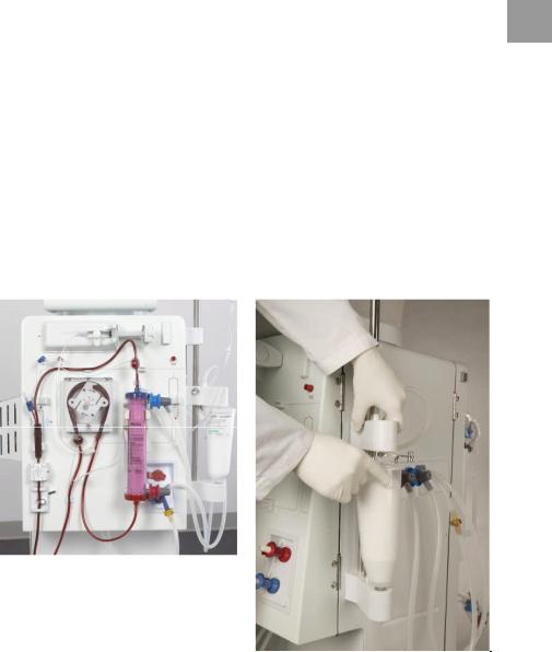
|
Dialog+® |
Product description |
2 Product description
The Dialog+ is a Hemodialysis Delivery System Machine available in four modelsModel # 710200K: Dialog+ single-pump
Model # 710200L: Dialog+ single-pump, with bicarbonate cartridge holder 2Model # 710200U: Dialog+ single-pump, with Adimea, DF filter, WAN-BSL
Model # 710200S: Dialog+ single-pump, with bicarbonate cartridge holder, Adimea, DF filter, WAN-BSL
The Dialog+ machine is suitable for hospital hemodialysis and also for dialysis centers. It can use and store different profiles for many parameters such as: UF, sodium, bicarbonate, heparin, dialysate flow, and temperature.
Treatment can be performed with bicarbonate or acetate concentrate supplied from a canister or from central supply. A bicarbonate cartridge can be used as well.
|
Model #710200L, single-pump |
Bicarbonate cartridge holder |
||||
|
configuration with bicarbonate |
|||||
|
cartridge holder |
|||||
|
Fig. 2-1 |
Dialog+ system models |
|
IFU 38910363US / Rev. 2.15.10 / May 2016 |
2-3 |

|
Product description |
Dialog+® |
2
“Disposables“
“Dialog+ machine“
2.1Components
The Dialog+ system consists of the following components:
Extracorporeal circulation system
Dialyzer
User interface
Control and safety monitoring systems, e.g. auto clamps, alarms, etc.
Balance chamber and UF control
Water preparation
Concentrate preparation
2.1.1Extracorporeal system
The extracorporeal system consists of the machine’s peristaltic pumps, which are used to transport the blood to the dialyzer and from the dialyzer back to the patient.
Blood is pumped through a disposable extracorporeal system mainly composed of tubing, connectors, drip chambers and the dialyzer.
Peristaltic pumps withdraw blood from the patient’s vascular access into the dialyzer. A syringe pump pumps heparin into the bloodlines in a quantity and time set by the user to avoid the coagulation of the blood in the disposable circuit and the dialyzer filter.
2.1.2Dialyzer
The capillary dialyzer houses semipermeable hollow fibers encased in a plastic canister. The dialyzer is used to correct the concentration of water-soluble substances in the patients blood before delivering it back to the patient. The blood is separated from the dialyzing fluid by a semi-permeable membrane that permits bidirectional diffusive transport and ultrafiltration. The process also allows diffusion of substances from the dialyzing fluid into the blood.
2.1.3User interface
The user interface is a display panel that provides communication between the machine and the user. On the display it is possible to visualize all the dialysis parameters and relevant information about the procedure and alarm conditions.
By touching the icons on the screen, the user can input all the parameters for the treatment such as: dialysis time, UF volume and heparin pump flow. Several profiles for the procedure can be selected and set via the interface.
The five buttons at the bottom of the screen (see Fig. 2-6) have fixed functions i.e., control the arterial pump, to enter and confirm the entry input and to reset the alarms.
|
2-4 |
IFU 38910363US / Rev. 2.15.10 / May 2016 |

|
Dialog+® |
Product description |
2.1.4Control system
The control system is divided into two parts:
The top level control system connects the interface with the user and transmits data 2 to and from other modules. The low level control system controls and monitors the machine and its functions and also communicates with the top level control system.
Both systems operate independently of each other.
2.1.5Balance chamber and UF-control
The balance chamber system is a closed system and consists of two chambers, each with a flexible membrane, allowing it to fill the chambers from one side while an identical volume is emptied to the other side. Therefore the outlet fluid volume is equal to the input fluid volume.
Each membrane has a magnetic sensor which reads the membrane position and controls the opening and the closing of each sub compartment.
The control of the dialysate volume is also carried out by the balance chamber. The difference between used dialysate and fresh dialysate is the ultrafiltration volume, which is removed from the blood side of the dialyzer. Ultrafiltrate removal is carried out by the UF pump.
2.1.6Water preparation
Purified water coming from the reverse osmosis system has to be degassed and tempered to a predetermined temperature, which is set by the user (usually 37°C/99 °F), before the concentrate is prepared. A degassing chamber and a heater are integral to the system.
2.1.7Concentrate preparation
In bicarbonate dialysis, which is the most common procedure, concentrate preparation consists of mixing the heated and degassed water with bicarbonate concentrate and acid concentrate. The accuracy of dialysate concentration is controlled by conductivity sensors. If the concentration is incorrect, the dialyzer will be bypassed.
|
IFU 38910363US / Rev. 2.15.10 / May 2016 |
2-5 |
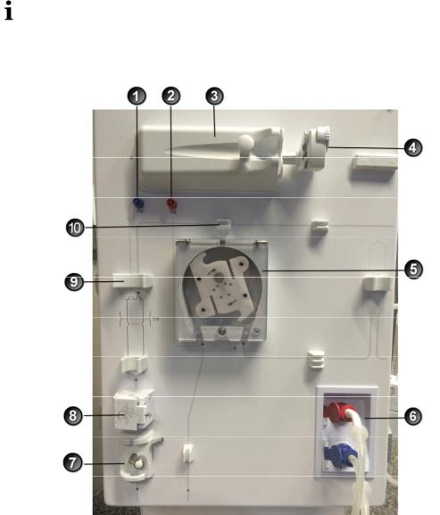
|
Product description |
Dialog+® |
|
2.2 |
Basic models |
|||||
|
2 |
||||||
|
The basic model Dialog+ single-pump machine is shown in the figure below. The |
||||||
|
legend highlights the components installed in all basic models. |
||||||
|
Front view |
||||||
|
Legend |
||||||
|
1 |
Venous pressure sensor |
|||||
|
connection (blue) |
||||||
|
2 |
Arterial pressure sensor |
|||||
|
connection (red) |
||||||
|
3 |
Heparin pump |
|||||
|
4 |
Syringe stop |
|||||
|
5 |
Blood pump (one or two blood |
|||||
|
pumps depending on basic |
||||||
|
model) |
||||||
|
6 |
Rinsing chambers for |
|||||
|
concentrate rods |
||||||
|
7 |
Venous tube clamp |
|||||
|
8 |
Safety air detector (SAD) and red |
|||||
|
sensor |
||||||
|
9 |
Fixture for the chamber of the |
|||||
|
blood tubing system |
||||||
|
10 |
Fixture for blood tubing system |
|
Fig. 2-2 |
Basic model single-pump, front view |
|
2-6 |
IFU 38910363US / Rev. 2.15.10 / May 2016 |

|
Dialog+® |
Product description |
Legend
1 Infusion pole (in
some models, pole 2 may not be
adjustable)
2Multi Functional Tray
3Bicarbonate cartridge holder (optional)
4Connection for central concentrate supply (optional)
5Connection for disinfectant
6Connections for dialyzer tubing and rinsing bridge
7Card reader
8Wheel lock
Fig. 2-3 Basic model, side views
|
IFU 38910363US / Rev. 2.15.10 / May 2016 |
2-7 |

1
2 2
3
4
|
Product description |
Dialog+® |
Legend
Mains switch
WAN-BSL
Crank for manual blood return
Fixture for disinfectant container
5Ground connection
6Power cord
7Water inlet
8Dialysate outlet
7Water inlet
8Dialysate outlet
Fig. 2-4 Basic model, rear view
|
2-8 |
IFU 38910363US / Rev. 2.15.10 / May 2016 |
|
Dialog+® |
Product description |
2.2.1Dialog+ single-pump machine
|
The Dialog+ single-pump dialysis machine is suitable for hospitals, health centers and |
||||
|
outpatient dialysis centers. It offers the following features as standard: |
2 |
|||
|
• |
Color screen and on-screen operation (color touch screen) |
|||
|
• |
Acetate/bicarbonate operation |
|||
|
• |
Volumetric ultrafiltration |
|||
|
• |
Heparin syringe pump |
|||
|
• |
Heat exchanger |
|||
|
• |
Fixed or freely selectable profile controls for dialysate composition, temperature |
|||
|
and flow rate, for heparin supply and for ultrafiltration |
The following features are available as additional accessories/options:
•Automatic blood pressure monitoring (ABPM)
•Bicarbonate cartridge holder
•Level regulation
•Central concentrate supply (ZKV)
•Dialysis fluid filter
•Dialysis fluid filter holder
•Emergency power supply
•Data interface
–Dialog+ computer interface (DCI)
–WAN BSL (Bed Side Link): Card reader and interface to data management system
–Card reader
•AdimeaTM Option UV–Kt/V
Therapy types
The Dialog+ dialysis machine with a single blood pump can be used for the following therapy procedures:
•Hemodialysis (HD) with or without phases of pure ultrafiltration
•High-flux hemodialysis
•Low-flux hemodialysis
Methods of treatment
The Dialog+ dialysis machine with a single blood pump can be used for the following therapy methods:
•Double-needle procedure
•Single-needle procedure
|
IFU 38910363US / Rev. 2.15.10 / May 2016 |
2-9 |

|
Product description |
Dialog+® |
2.3Symbols on the dialysis machine
2
Observe Instructions for Use Observe Safety information
Type B applied part
Classification acc. to IEC 60601-1
Type BF applied part
Classification acc. to IEC 60601-1
Electrical ground
Dialysis machine OFF
Dialysis machine ON
Alternating current
Schematic illustration on safety air detector (SAD), showing the correct way of installing the tube
Connection for optional automatic blood pressure monitoring (ABPM)
|
2-10 |
IFU 38910363US / Rev. 2.15.10 / May 2016 |
![]()
|
Dialog+® |
Product description |
2.4 Control elements and information on the monitor
|
Signal lamps |
2 |
||
|
Signal lamps on the left and right of the monitor light up in three different colors to |
|||
|
indicate the conditions «Operation», «Warning» and «Alarm». |
Legend
1Signal lamps: Green = operation
Yellow = warning/note Red = alarm
2Buttons on the monitor
Buttons on the monitor
Even with the screen switched off (e.g. during cleaning), the basic functions of the dialysis machine can be controlled via the buttons on the monitor.
The “+” and “-“ buttons (buttons 2 and 4) automatically count up or down by holding the button down.
|
Fig. 2-6 Buttons on the monitor |
|||
|
Legend |
|||
|
1 |
Battery symbol (display only): Battery charging |
4 |
Increase blood pump speed |
|
2 |
Reduce blood pump speed |
5 |
Confirm alarm (when button is illuminated); switches off |
|
the alarm buzzer |
|||
|
3 |
Switch on/switch off blood pump |
6 |
Enter button: Confirm entered data and reset information |
|
(if button is illuminated) |
|
IFU 38910363US / Rev. 2.15.10 / May 2016 |
2-11 |

|
Product description |
Dialog+® |
|
Touch Screen |
|||
|
Most functions of the dialysis machine are controlled via the touch screen. |
|||
|
The screen displays different contents (windows) depending on the activated program |
|||
|
2 |
|||
|
section. Different parts (fields and icons) of the screen react to touch. By touching one |
|||
|
of these areas, another window is called up or a stored action is triggered. |
|||
Some windows show a lateral scroll bar. They could be scrolled by moving a finger on the scroll bar.
Legend
1Screen
2Fields
3Icons
4Call up help function for explaining the icons
Fig. 2-7 Screen display
|
2-12 |
IFU 38910363US / Rev. 2.15.10 / May 2016 |

|
Dialog+® |
Product description |
2.5Overview of all icons
Icons are control buttons on the touch screen used for operating the dialysis machine. Depending on the displayed window, different icons are available, which all represent 2 a specific action. By touching an icon, the respective action is carried out. A list of all
icons is provided below.
Leave window and accept data
Leave window without accepting data
Help function for explaining the icons
History of current disinfection
Service screen
Switch off all icon functions for 10 sec to allow cleaning of monitor
Set brightness of monitor
Leave current window
Overview/ Table of contents
Related parameter window
|
IFU 38910363US / Rev. 2.15.10 / May 2016 |
2-13 |

|
Product description |
Dialog+® |
||||||
|
Set treatment parameters |
|||||||
|
2 |
|||||||
|
Return to program selection |
|||||||
|
Erase chip card |
|||||||
|
Read patient data from chip card |
|||||||
|
Save patient data to chip card |
|||||||
|
Select further setting options |
|||||||
|
Reduce value |
|||||||
|
Increase value |
|||||||
|
Red symbol: error symbol during reading of patient data from chip card |
|||||||
|
to be consistent |
|||||||
|
In profile window (except for UF profile): open numerical keypad for |
|||||||
|
resetting the profile to a setting |
|||||||
|
Key pad for entering numerical values |
|||||||
|
Give heparin bolus |
|||||||
|
Give arterial bolus (e.g. saline) |
|||||||
|
2-14 |
IFU 38910363US / Rev. 2.15.10 / May 2016 |

|
Dialog+® |
Product description |
Window for setting arterial bolus
2
Dialyzer rinsing program with simultaneous ultrafiltration
Empty dialyzer – dialysate is siphoned out of the dialyzer
Set heparinization data
Reset filter, empty (option DF filter)
Filter data (only active if option DF filter has been installed)
Save filter data to card reader
Dialysis on main connection – dialysate flows through dialyzer
Dialysis bypass – no dialysate in dialyzer
Start reinfusion
Change bicarbonate cartridge
|
IFU 38910363US / Rev. 2.15.10 / May 2016 |
2-15 |

|
Product description |
Dialog+® |
Change to therapy mode
2
Change to «Therapy end» mode
Disinfection from water supply – inlet
Disinfection from water supply – discharge
Set dialysate data
Activate stand-by
Set ultrafiltration data
Minimum ultrafiltration
Set pressure limits
Single-needle selection and settings
Ultrafiltration profiles
Profile settings for the respective parameter
|
2-16 |
IFU 38910363US / Rev. 2.15.10 / May 2016 |

|
Dialog+® |
Product description |
Linear profile in case of specified start and end values
2
Exponential profile in case of specified start and end values
Non-invasive blood pressure monitoring (ABPM, option)
Time setting (ABPM, option)
Graphic representation of different parameters of therapy course
Determine selection of graphically represented parameters
Screen for entering laboratory values (urea) for Kt/V calculation
UV-Kt/V measurement (option AdimeaTM)
Save dialysis effectiveness and list of treatment values and Kt/V values
Save disinfection data
Weekly disinfection program
Disinfection screen
|
IFU 38910363US / Rev. 2.15.10 / May 2016 |
2-17 |

|
Product description |
Dialog+® |
||||||
|
Start thermal disinfection |
|||||||
|
2 |
|||||||
|
Start central thermal disinfection |
|||||||
|
Start chemical disinfection from water supply |
|||||||
|
Start brief disinfection/cleaning |
|||||||
|
Start disinfection program |
|||||||
|
Start central rinsing |
|||||||
|
Activate automatic switch-on of dialysis machine at the programmed |
|||||||
|
time |
|||||||
|
Activate automatic switch-off of dialysis machine after disinfection |
|||||||
|
Disinfection history of last 150 disinfections |
|||||||
|
Delete ABPM measured values list (option) |
|||||||
|
Start ultrafiltration without dialysate (sequential therapy) |
|||||||
|
Start ultrafiltration with dialysate |
|||||||
|
Timer/stop watch |
|||||||
|
2-18 |
IFU 38910363US / Rev. 2.15.10 / May 2016 |

|
Dialog+® |
Product description |
Suppressed warning sounds during preparation
2
Select language of screen text
Level regulation: enter to level regulation function
Level regulation: decreasing chamber level
Level regulation: increasing chamber level
List of stored AdimeaTM curves
|
IFU 38910363US / Rev. 2.15.10 / May 2016 |
2-19 |

|
Product description |
Dialog+® |
|
2.6 |
Entering numerical values |
|||
|
2 |
The changing of values is based on the same principle for all parameters. We are |
|||
|
therefore providing an example. The example refers to the change of the parameter UF |
||||
|
quantity on the ultrafiltration data window. |
||||
|
Touch icon on window. |
The selected icon lights up in green.
An icon appears for all parameter groups that can be changed.
If none of these icons is pressed within a preset time, the icons are switched off again. The preset time can be set by the service engineer in the service program.
Touch desired icon (shown here: icon for calling up ultrafiltration data window, see Fig. 2-8).
The selected icon lights up in green.
The preset values for the parameter are displayed.
Touch value to be changed on screen (shown here: value for UF quantity 2000 mL, see Fig. 2-8).
A field of icons for changing the value is displayed. The desired value lights up in green.
Legend
1Reduce value
2Increase value
3Call up keypad for entering values
4Example: Calling up ”Ultrafiltration data” screen
Fig. 2-8 Icons for changing the value
|
2-20 |
IFU 38910363US / Rev. 2.15.10 / May 2016 |
![]()
Dialog+® Product description
The dialysis machine can be set in the service program in such a way that a keypad appears immediately after the value to be changed has been touched. In this case, the keypad has no O.K. icon. To confirm entry, press on the monitor.
2
Reduce value: Touch icon 1 until the desired value has been reached.
Increase value: Touch icon 2 until the desired value has been reached.
Enter different value: Touch icon 3.
A keypad is displayed. The permissible setting range is specified in square brackets below the numerical value (shown here: 100 … 20000, see Fig. 2-9).
By pressing the icons 1 and 2, the setting could be adjusted up or down.
Legend
1Numerical keys
2Change sign of numerical value
3Delete set numerical value
4Leave window and accept data
5Leave window without accepting data
Fig. 2-9 Numerical keypad
Delete the set numerical value: Touch key 3 on keypad.
Interrupt entry of numerical value and return to main window: Touch key 5.
If a value outside the permissible range is entered, the message Limits exceeded is displayed below the entered value.
Enter value using keypad keys 1.
If necessary, change sign via icon 2.
Confirm entry with icon 4.
|
IFU 38910363US / Rev. 2.15.10 / May 2016 |
2-21 |

|
Product description |
Dialog+® |
To access all of the groups of parameters, “shortcuts” can be used. Touch the parameter which should be changed or a concerning graphic indicator on the main screen. The corresponding window of the group of parameters will open as shown in Fig. 2-10.
2
The following screen shows the available shortcut squares in frames.
Legend
1 Help icon, active
Shortcuts
Fig. 2-10 Shortcut squares during activated help button
If a “shortcut” was touched inadvertently, or if no parameters are entered, the parameter window will close automatically after 10 seconds.
The frames marking the shortcuts will only appear if the help function is activated.
Touch help button (1).
The “shortcuts“ will be marked by brown frames.
Touch help button again.
The frames disappear.
Shortcuts are only active if the corresponding parameters are relevant for the actual therapy. For example: The setting of the venous limit can only be done by shortcut within Single-needle (SN) therapies.
Some shortcuts directly open the +/- window for changing the setting. For example: UF-quantity.
|
2-22 |
IFU 38910363US / Rev. 2.15.10 / May 2016 |

|
Dialog+® |
Product description |
2.7Using the timer/stop watch
|
The Dialog+ screen offers a timer or stop watch function for individual use. |
2 |
|||
|
These functions are offered in the following phases: |
||||
|
• |
Preparation |
|||
|
• |
Therapy |
|||
|
• |
End of Therapy |
|||
|
• |
Selection of disinfection |
|||
|
• |
Disinfection |
Touch this icon.
Touch this icon.
The following screen will appear.
Legend
1Adjustment of an absolute time for a warning sound
2Adjustment of an interval time for a warning sound
3Displays rest or expired time
4Starts/Stops/resets timer or stop watch
5Starts/stops the timer for recurring warnings after input in
1 or 2
6Switches off the warning sound after the chosen time interval
7Opens an input window for reminder
Fig. 2-11 Timer/stop watch function
If requested, button 6 activates or inactivates the warning sound.
The user could choose between a single warning or a cyclic warning with fixed intervals.
|
IFU 38910363US / Rev. 2.15.10 / May 2016 |
2-23 |

|
Product description |
Dialog+® |
For a single warning
Requested adjustment with button 1 or 2.
Touch button 4 for single warning.
2
For cyclic warning:
Requested adjustment with button 2 (button 5 automatically activated)
Touch button 5
The timer/stop watch function starts.
To stop/reset touch respective button.
The timer function is counting the time shown in field 3 downwards, the stop watch is counting upward.
Touch button 7 for input of a reminder.
At expiry of an adjusted time a prompt appears in the message field “The set time interval expired” or an information window with written reminder appears. The signal lamps switch to yellow and an acoustic signal appears if it has been activated.
Press the button to acknowledge sound and message.
The timer/stop watch function is not interrupted by a possible power failure.
The running timer/stop watch function is shown with a symbol in the date line of the screen.
|
Fig. 2-12 |
Date line with timer symbol |
|
2-24 |
IFU 38910363US / Rev. 2.15.10 / May 2016 |

|
Dialog+® |
Installation and commissioning |
Table of contents
3
|
3 |
Installation and commissioning…………………………………………………. |
3-3 |
||
|
3.1 |
Scope of supply ………………………………………………………………………… |
3-3 |
||
|
3.2 |
Storage …………………………………………………………………………………….. |
3-3 |
||
|
3.2.1 Storage in originally packed condition ……………………………………….. |
3-3 |
|||
|
3.2.2 Interim storage of devices ready for operation ………………………….. |
3-3 |
|||
|
3.2.3 |
Decommissioning ………………………………………………………………………….. |
3-3 |
||
|
3.3 |
Transportation ………………………………………………………………………….. |
3-4 |
||
|
3.3.1 |
Rolling ……………………………………………………………………………………………. |
3-4 |
||
|
3.3.2 |
Carrying………………………………………………………………………………………….. |
3-5 |
||
|
3.4 |
Installation site…………………………………………………………………………. |
3-6 |
||
|
3.4.1 |
Electrical connection ……………………………………………………………………. |
3-6 |
||
|
3.4.2 Protection against water damage ……………………………………………….. |
3-6 |
|||
|
3.4.3 |
Potentially explosive areas …………………………………………………………… |
3-6 |
||
|
3.5 |
Water supply…………………………………………………………………………….. |
3-7 |
||
|
3.5.1 Quality of water and dialysate…………………………………………………….. |
3-7 |
|||
|
3.5.2 |
Disposal of used fluids………………………………………………………………….. |
3-7 |
||
|
3.6 |
Initial commissioning ………………………………………………………………… |
3-8 |
||
|
3.7 |
Setting date and time……………………………………………………………….. |
3-8 |
||
|
3.8 |
Switching on and off ………………………………………………………………… |
3-9 |
|
IFU 38910363US / Rev. 2.15.10 / May 2016 |
3-1 |

|
Installation and commissioning |
Dialog+® |
3
|
3-2 |
IFU 38910363US / Rev. 2.15.10 / May 2016 |
|
Dialog+® |
Installation and commissioning |
3 Installation and commissioning
3.1Scope of supply
|
Dialog+ dialysis machine |
||||
|
Instructions for Use |
3 |
|||
|
Suction tube with screw lid for disinfectant |
||||
Tube clamps for tubes
One container lid each with coupling for inserting suction rods (red and blue)
Storage box
•In case of option Central Concentrate Supply: Supply from wall connection coupling to dialysis machine
Special accessories
Check-in goods
Unpack dialysis machine and check for completeness and damage.
If there is damage, call technical service.
3.2Storage
3.2.1Storage in originally packed condition
Store the dialysis machine in ambient conditions, as specified in section 15.2.
3.2.2Interim storage of devices ready for operation
Disinfect the dialysis machine.
Store the dialysis machine in ambient conditions, as specified in section 15.2.
3.2.3Decommissioning
Disinfect the dialysis machine.
Instruct technical service to empty the dialysis machine.
Store the dialysis machine in ambient conditions, as specified in section 15.2.
|
IFU 38910363US / Rev. 2.15.10 / May 2016 |
3-3 |

|
Installation and commissioning |
Dialog+® |
3.3Transportation
3.3.1Rolling
|
3 |
Risk of damage if dialysis machine is tilted by more than 10°! |
|
|
Have 2 or more persons at hand for transporting the machine on stairs and |
||
|
CAUTION |
inclined areas. |
|
|
Do not tilt the dialysis machine by more than 10°. |
||
|
Fig. 3-1 |
Transport on stairs and slopes (2 persons) |
Release both brakes of front casters.
Wheel the dialysis machine.
Apply both brakes of front casters.
|
3-4 |
IFU 38910363US / Rev. 2.15.10 / May 2016 |

|
Dialog+® |
Installation and commissioning |
3.3.2Carrying
For carrying, the dialysis machine can be held at the base, at the rear panel and/or the protrusion at the front of the machine, as shown in the following illustration.
3
|
Fig. 3-2 |
Holding points for carrying the dialysis machine |
Danger of damage due to incorrect transportation (wrong holding points)!
|
CAUTION |
Do not hold machine on monitor, on bicarbonate cartridge holder or on |
|
infusion pole when transporting. |
Use a belt to secure monitor to infusion pole.
Release caster brakes.
Tilt the dialysis machine.
Put down the dialysis machine.
Apply caster brakes.
|
IFU 38910363US / Rev. 2.15.10 / May 2016 |
3-5 |

|
Installation and commissioning |
Dialog+® |
||||||
|
3.4 |
Installation site |
||||||
|
Ambient conditions |
|||||||
|
3 |
Observe information about ambient conditions, see section 15.2. |
||||||
|
3.4.1 |
Electrical connection |
||||||
|
The existing mains voltage must correspond with the voltage specified on the rating |
|||||||
|
plate. |
|||||||
|
The use of extension cables or adapters with the power cable or the mains socket is |
|||||||
|
NOT permitted. Modifications of the power cable are forbidden! If the power cable has |
|||||||
|
to be changed, only the original power cable listed in the spare parts list must be used. |
|||||||
|
Electrical installations in the room where the dialysis machine will be operated must |
|||||||
|
conform with relevant regulations, e.g. IEC-stipulations. Regulations and deviations |
|||||||
|
specific to the individual country must also be observed. For further information, ask |
|||||||
|
technical service. |
|||||||
|
Using devices of protection class I the quality of the protective conductor is important. |
|||||||
|
Regulations and deviations specific to the individual country must also be observed. |
|||||||
|
For further information, ask technical service. |
|||||||
|
Each Dialog+ machine requires a dedicated 20 amp electrical service, with an isolated |
|||||||
|
ground. |
|||||||
|
Grounding reliability can only be achieved when equipment is connected to an |
|||||||
|
equivalent receptacle marked “hospital only” or “hospital-grade”. North American |
|||||||
|
medical equipment cords and plugs have to be «hospital-grade» or «hospital only», |
|||||||
|
meaning they are subject to special requirements contained in relevant applied |
|||||||
|
standards. It is imperative that the ground connection be reliably maintained to |
|||||||
|
protect the patient and medical staff. Hospital-grade power cords and cordsets carry |
|||||||
|
the «green dot» signifying that they have been designed and tested for grounding |
|||||||
|
reliability, assembly integrity, strength and durability. |
|||||||
|
3.4.2 |
Protection against water damage |
||||||
|
We recommend the use of water detectors to protect against any unnoticed water |
|||||||
|
leakages. |
|||||||
|
3.4.3 |
Potentially explosive areas |
||||||
|
The dialysis machine may not be operated in areas at risk of explosion. |
|
3-6 |
IFU 38910363US / Rev. 2.15.10 / May 2016 |
 Loading…
Быстрый поиск по продуктам
Гемодиализный аппарат «Искусственная почка» Dialog+ (Диалог+)
Для экстракорпорального очищения крови при хронической почечной недостаточности
Концепция Диалог+ предусматривает три основные конфигурации аппарата для экстракорпоральных процедур. Система разработана в соответствии с международными требованиями пациентов и медицинского персонала.
Интегрированная и эффективная терапевтическая система позволяет пользователю получить максимальное количество вариантов индивидуальной комплектации каждого диализного аппарата. Новое поколение аппаратов Диалог+ демонстрирует комфортные нововведения для оператора и пациента. Эти новшества так же соответствуют современным экономическим и медицинским требованиям. Комплектующие, принадлежности и расходные материалы от одного производителя наилучшим образом соответствуют друг другу и образуют единую терапевтическую систему. Современная медицинская технология высокого качества в совокупности с интеллектуальными компонентами и одним последовательным общей доминантой: оптимальное качество лечения для пациентов.
Б. Браун — мы делимся опытом, чтобы поддержать вас в любое время.
Сопутствующие продукты

Кровопроводящие магистрали
Больше

Опция bioLogic RR Comfort
Больше

Фильтры диализата Diacap Ultra
Больше

Дезинфицирующее средство Tiutol® KF (Тиутол® КФ)
Больше
Дезинфицирующее средство «Лимонная кислота 50 %» (Citric acid 50%)
Больше

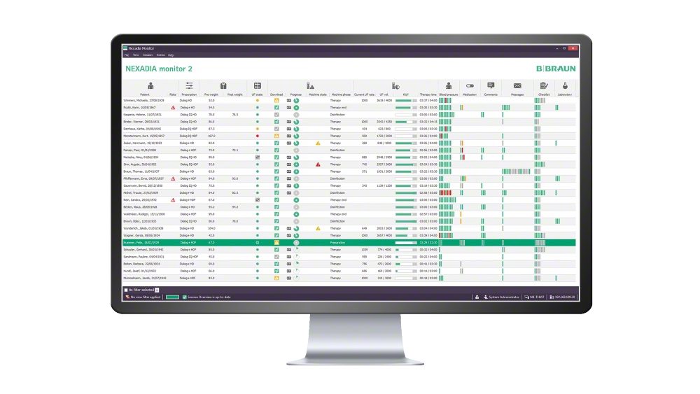
Снят с производства
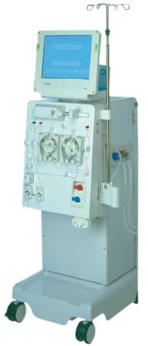
Поставщики и цены:
Аппарат искусственная почка DIALOG+
Гемодиализный аппарат DIALOG.
Для проведения гемодиализа или любого другого экстракорпорального метода лечения аппарат DIALOG является оптимальным выбором.
Аппарат «искусственная почка» нового поколения фирмы B.Braun, разработанный на базе ультрасовременной технологии, позволяет проводить любые варианты диализной терапии, известные на сегодняшний день включая стандартную гемодиафильтрацию и гемодиафильтрацию «он-лайн».
Представление информации, касающейся процедуры, осуществляется на цветном сенсорным мониторе в виде пиктограмм.
DIALOG обеспечивает
— самотестирование перед процедурой;
— программирование всех параметров процедуры;
— точное волюметрическое управление ультрафильтрацией с любым диализатором с точностью до 10-30 мл/час,
— проведение ацетатного или бикарбонатного диализа,
— одноигольное подключение больного с постоянным потом крови через диализатор,
— профилирование по натрию, бикарбонату и ультрафильтрации, скорости потока диализной жидкости и введению гепарина,
— стерилизацию диализата,
— подключение сухого бикарбонатного концентрата,
— измерение артериального давления,
— мониторинг ЭКГ,
— связь с центральным компьютером.
DIALOG имеет много уникальных возможностей таких как :
— выбор языка общения с аппаратом (русский, английский, немецкий);
— большой набор стандартных профилей для индивидуализации процедуры лечения;
— Програмируемая по времени химическая, тепловая и холодная дезинфекция;
— рассчёт kt/V в конце лечения;
— дискета для хранения данных пациента и загрузки параметров проведения терапии;
— автоматическое включение/выключение аппарата,
— вращающийся на 180 º монитор.
Аппарат искусственная почка DIALOG+ Технические характеристики
— Контур диализата
температурные пределы 33 — 400 С
Объем заполнения: (мл) под контролем кондуктивности
границы контроля: кондуктивность бикарбоната от 2 до 4 мС/см или от 4 до 7 мС/см
общая кондуктивность от 12 до 17 мС/см
чувствительность: 0,2 мС/см
скорость диализата: от 300 до 800 мл/мин
детектор утечки крови: оптический, цветоспецифический
тревога: через балансировочную камеру под контролем объема
частичная ультрафильтрация
границы ультрафильтрации: от 0 до 3 000 мл/час
точность: 3%
система деаэрации: механическая под контроле датчика негативного давления
— Экстракорпоральный контур
насос крови: перистальтический, 2-х роликовый насос
скорость: от 50 до 600 мл/мин
точность: 10%
уровень давления: 20 — 390 мм Hg
насос замещающий: от 500 до 5 000 мл/мин
точность: 0,5%
насос гепариновый: шприцы от 20 до 50 мл
скорость от: 0,1 до 10 мл/час
точность: 10%
уровень давления: от — 200 до +480 мм Hg
детектор контроля воздуха: ультразвукового типа
рабочий принцип: звуковой алярм при появлении воздушных пузырьков или опорожнении каплеобразующей камеры
функциональный тест проводится: автоматически или циклически в течении всего времени работы
контроль давления на входе в диализатор: от 0 до 700 мм Hg
точность: 12 мм Hg
контроль артериального давления: от -400 до +400 мм Hg
точность: 12 мм Hg
контроль венозного давления 1от: 10 до 390 мм Hg
точность: 12 мм Hg
— Дезинфекция
дезинфекция: проводится в период остановки гемодиализа
химическая дезинфекция: автоматическая программа хода дезинфекции либо адаптированная к определенному виду дезинфектанта
горячая дезинфекция : автоматическая программа хода при температуре 850 С
— Общие сведения
номинальное напряжение: 230 В (дополнительно: 110/120/240 В)
номинальная частота : 50/60 Гц
номинальная сила тока максимально: 10 А (или 20 А)
размеры (ширина х глубина х высота, мм): 555 х 625 х 1450
вес (кг): в стандартной комплектации — 101
водоснабжение: вода удовлетворящая по качеству воде для гемодиализа
уровень давления: от 0,5 до 10 бар
температурный уровень: от 5 до 300 С
снабжение концентратом канистры ( или централизованное, как дополнительная функция) бикарбонатные картриджи
уровень давления: от 0 до 1 бара
Дополнительные принадлежности:
— централизованное снабжение концентратом
— холдер бикарбонатного картриджа
— дополтельный замещающий насос
— блок гемодиафильтрации
— фильтр пирогенный
— блок неинвазивного измерения артериального давления
— интерфейс
— стойка инфузионная
— теплообменник
— блок памяти о пациентах