- Manuals
- Brands
- Flight Medical Innovations Manuals
- Fan
- Flight 60 Ventilator
Manuals and User Guides for Flight Medical Innovations Flight 60 Ventilator. We have 3 Flight Medical Innovations Flight 60 Ventilator manuals available for free PDF download: Operator’s Manual, Setting Up
Flight Medical Innovations Flight 60 Ventilator Operator’s Manual (130 pages)
Turbine Ventilator
Brand: Flight Medical Innovations
|
Category: Fan
|
Size: 2.66 MB
Table of Contents
-
W Arnings
3
-
Table of Contents
7
-
1 Introduction
11
-
Intended Use
11
-
Symbols
12
-
-
2 Safety Instructions
15
-
General Warnings
15
-
Cautions
18
-
-
3 Ventilator Description
21
-
Front Panel Features
21
-
Control Buttons
22
-
LED Indicators
23
-
-
Back Panel Features
24
-
Left Side Panel Features
25
-
Right Side Panel Features
26
-
-
4 Installation
27
-
Introduction
27
-
Removing the Ventilator Parts from the Box
27
-
Mounting the Ventilator
27
-
Installing the Detachable and Integral Batteries
28
-
Plugging in the Power Cord (for AC)
28
-
Attaching the Patient Circuit
29
-
Circuit Test
30
-
Connecting the Oxygen Supply
31
-
Internal O Mixer
32
-
Low-Flow Oxygen Port
32
-
-
-
5 Basic Operation
35
-
Powering on the Ventilator
35
-
Initiating Ventilation
36
-
Turning off the Ventilator
36
-
Navigating between Screens
37
-
Setting Control Values
37
-
Default and Saved Values
38
-
-
-
6 Ventilator Settings
39
-
Home (Parameters) Screen
39
-
Pop-Up Messages
44
-
-
Extended Screen
46
-
Alarms Screen
48
-
Technical Screen
49
-
-
7 Ventilator Alarms and Backup Ventilation
53
-
Audible Alarm and Caution Signals
53
-
Visual Alarm and Caution Signals
54
-
Alarm and Caution Specifications
55
-
Variable Ventilation Alarms
55
-
Automatic Ventilation Alarms
56
-
Automatic Technical Alarms
57
-
Cautions (Low Priority)
58
-
-
Apnea Backup Ventilation
59
-
Backup Ventilation in ACMV and SIMV Modes
60
-
Backup Ventilation in SPONT, MVG and VTG Modes
60
-
Backup Ventilation in B-LEV Mode
60
-
Cancellation of Backup Ventilation
60
-
Customized BUV
60
-
-
Low Power Ventilation (Lpv)
61
-
Cancellation of LPV Ventilation
61
-
-
Silencing Audible Alarms
62
-
Resetting Alarms
62
-
Disabling the Check Circuit Alarm
62
-
Disabling the Low P Alarm
63
-
Setting up a Remote Alarm
64
-
-
8 Monitoring
65
-
Graphic Display
65
-
Waveforms and Loops
65
-
Trends
66
-
Selecting Trended Parameters
67
-
Time Scale Adjustment
67
-
-
Lung Mechanics Monitoring Display
67
-
Rsbi Monitoring
69
-
Additional Monitoring Parameters Display
69
-
Numeric Display
70
-
-
9 Ventilation Modes
71
-
ACMV Mode (Assist/Control Mandatory Ventilation)
71
-
SIMV Mode (Synchronized Intermittent Mandatory Ventilation)
71
-
VC/Pc/Prvc
72
-
-
SPONT Mode (Spontaneous Ventilation)
77
-
VG (Volume Guarantee)
77
-
B-LEV Mode (Bi-Phasic Ventilation)
80
-
NIV (Non-Invasive Ventilation) Sub Mode Auto-Alarm Function
81
-
-
10 Special Functions
83
-
Nebulizer (Optional)
83
-
Minutes 100% O2 (Optional)
84
-
Sigh
84
-
Manual Breath
85
-
Panel Lock
85
-
Quick-Start and Preset Ventilation Configurations
86
-
Quick-Start: Factory Default Settings
87
-
Setting and Loading the Preset Ventilation Configurations
87
-
-
I N -Use O 2 Sensor Calibration
88
-
Altitude Compensation
90
-
-
11 Cleaning and Maintenance
91
-
Cleaning and Disinfecting
91
-
FLIGHT 60 Ventilator
91
-
FLIGHT 60 Ventilator Accessories
92
-
-
Maintenance
97
-
Preventive Maintenance
97
-
Internal Battery Maintenance
98
-
Sensor Maintenance
98
-
Hour Maintenance
98
-
-
General Warnings
99
-
-
12 Troubleshooting
101
-
Introduction
101
-
Alarms
101
-
General/Clinical
105
-
Oxygen Enrichment
109
-
-
13 Contact Information
110
-
14 Ventilator Quick Check Procedure
111
-
Introduction
111
-
Setting up the Ventilator for the Test
111
-
-
Quick Check Procedure
112
-
Checking the Power Management
112
-
Checking the Alarms
113
-
Checking the Monitored Parameters
113
-
-
Check-Off Sheet
114
-
-
15 Technical Specifications
115
-
Physical Specifications
115
-
Pneumatic Specifications
115
-
Electromagnetic Emission — Guidance and Manufacturer’s Declaration
115
-
Recommended Separation Distance between Portable Mobile RF Communications Equipment and the Device
119
-
Recommended Separation Distances between Power Buses and the Product
120
-
EMC Statement of Essential Performance
120
-
-
Electrical Specifications
121
-
Internal Battery Specifications
121
-
Safety and Particular Standard Specifications
122
-
Environmental Specifications
122
-
Internal O2 Mixer
123
-
Oxygen Blending Bag Kit Specifications
123
-
Low Flow Port Oxygen Specifications
124
-
Internal Oxygen Sensor Specifications
124
-
-
16 Index
125
Advertisement
Flight Medical Innovations Flight 60 Ventilator Operator’s Manual (101 pages)
Brand: Flight Medical Innovations
|
Category: Medical Equipment
|
Size: 2.27 MB
Table of Contents
-
Flight 60 Ventilator
1
-
Warranty
3
-
About this Document
5
-
Table of Contents
7
-
-
Table of Contents
8
-
1 Introduction
12
-
Intended Use
12
-
Symbols
12
-
Overview
13
-
-
2 Safety Instructions
14
-
General Warnings
14
-
Cautions
17
-
-
3 Ventilator Description
19
-
Front Panel Features
19
-
LED Indicators
20
-
-
Back Panel Features
21
-
Left Side Panel Features
22
-
Right Side Panel Features
23
-
Lcd Screens
23
-
Alarm and Power Management Area
23
-
Patient Monitoring Area
24
-
Control Area
25
-
Parameters Screen
25
-
Extended Screen
27
-
Technical Screen
28
-
-
Accessories
30
-
Air/Oxygen Entrainment Mixer
30
-
Oxygen Blending Bag Kit
30
-
Operator’s Manual
32
-
-
-
4 Installation
32
-
Introduction
32
-
Removing the Ventilator Parts from the Box
32
-
Mounting the Ventilator
32
-
Installing the Detachable Battery
33
-
Plugging in the Power Cord (for AC)
33
-
Attaching the Patient Circuit
34
-
Installing Oxygen Accessories
35
-
The Air/Oxygen Entrainment Mixer
36
-
Installing the Air/Oxygen Entrainment Mixer
37
-
The Oxygen Blending Bag Kit
38
-
Installing the Oxygen Blending Bag Kit
39
-
Disassembling and Cleaning the Oxygen Blending Bag Kit
40
-
Monitoring the Oxygen Supply Flow in the Oxygen Blending Bag
40
-
-
-
-
5 Using the Ventilator
43
-
Basic Operation
43
-
Powering on the Ventilator
43
-
Turning off the Ventilator
44
-
Navigating between Screens
44
-
Setting Control Values
44
-
Default and Saved Values
45
-
Delivering a Manual Breath
45
-
Locking the Panel
45
-
Accepting Parameter Adjustments
46
-
Canceling Parameter Adjustments
46
-
Changing Parameter Value (Up/Down Button)
46
-
-
Setting the Main Parameters
46
-
ACMV Mode
46
-
Mode of Operation
46
-
SIMV Mode (Synchronized Intermittent Mandatory Ventilation)
47
-
SPONT Mode (Spontaneous Ventilation)
48
-
Submode of Operation (VCV/PCV)
48
-
Volume Control Ventilation (VCV)
49
-
-
Pressure Control Ventilation (PCV)
51
-
Inspiratory Time (Ti) / Flow
52
-
-
Inspiratory Time
53
-
Flow Rate
53
-
Frequency of Breaths (F)
54
-
Pressure Trigger Level (Ptrig)
54
-
Positive End Expiratory Pressure (PEEP)
55
-
Pressure Support Ventilation (PSV)
55
-
Lower and Upper Pressure Limits (Low P, High P)
56
-
Lower and Upper Minute Volume Alarm Limits (Low MV, High
57
-
-
Low MV
57
-
High MV
58
-
Settings Limitation Pop-Up Messages
58
-
-
-
Setting the Extended Parameters
59
-
Alarm Buzzer Volume
59
-
Activating/Deactivating Power Saving
59
-
Waveform Type
60
-
-
VIII | Flight
60
-
Inspiratory Time / Flow Control (TI / Flow Ctl.)
61
-
Rise Profile
61
-
Pressure Support Flow Termination (PSV Flow Term)
62
-
Pressure Support Ventilation Inspiratory Time (PSV Ti)
63
-
Activating/Deactivating the O2 Enrichment Monitor (Fio2)
63
-
High and Low Levels for the Oxygen Alarm (Fio2 Low and Fio2 High)
64
-
Apnea
64
-
Backup Ventilation in ACMV and SIMV Modes
65
-
Backup Ventilation in SPONT Mode
65
-
Cancellation of Backup Ventilation
65
-
-
Setting the Technical Parameters
66
-
Activating/Deactivating the SPONT Mode Low Pressure Alarm (LOW P Spont)
66
-
Pressure Units Display (Press Units)
66
-
System Language
66
-
Displaying the System Information
67
-
Performing Exhalation Valve Calibration
67
-
Storing/Loading a Ventilation Configuration
68
-
Displaying the Alarms/Changes Log
69
-
System Clock
69
-
Accessing the Advanced Technical Menu
70
-
Initiating Ventilation
70
-
Monitoring the Patient
71
-
-
-
-
6 Ventilator Alarms
72
-
Audible Alarm and Caution Signals
72
-
Visual Alarm and Caution Signals
72
-
Alarm and Caution Specifications
73
-
Variable Ventilation Alarms
73
-
Automatic Ventilation Alarms
74
-
Automatic Technical Alarms
74
-
Cautions
75
-
Silencing Audible Alarms
75
-
Resetting Alarms
76
-
Setting up a Remote Alarm
76
-
-
-
7 Cleaning and Maintenance
77
-
Cleaning and Disinfecting
77
-
FLIGHT 60 Ventilator
77
-
FLIGHT 60 Ventilator Accessories
77
-
Oxygen Blending Bag Kit
78
-
Reusable (Single Patient) Patient Circuits
78
-
Reusable (Single Patient) Exhalation Valve
80
-
FLIGHT 60 Ventilator Air Inlet Particle Filter
82
-
Maintenance
82
-
Preventive Maintenance
82
-
Hour Maintenance
83
-
Internal Battery Maintenance
83
-
-
General Warnings
84
-
-
-
8 Troubleshooting
85
-
Introduction
85
-
Alarms
85
-
General/Clinical
88
-
Air/Oxygen Entrainment Mixture
93
-
Contact Information
94
-
-
9 Ventilator Quick Check Procedure
95
-
Introduction
95
-
Setting up the Ventilator for the Test
95
-
-
Quick Check Procedure
96
-
Checking the Power Management
96
-
Checking the Alarms
97
-
Checking the Monitored Parameters
97
-
-
Check-Off Sheet
98
-
-
10 Technical Specifications
99
-
Physical Specifications
99
-
Pneumatic Specifications
99
-
Electrical Specifications
99
-
Internal Battery Specifications
100
-
Safety and Particular Standard Specifications
100
-
Environmental Specifications
101
-
Air/Oxygen Entrainment Mixer Specifications
101
-
Oxygen Blending Bag Kit Specifications
101
-
Flight Medical Innovations Flight 60 Ventilator Setting Up (2 pages)
Brand: Flight Medical Innovations
|
Category: Respiratory Product
|
Size: 0.75 MB
Advertisement
Advertisement
Related Products
-
Flight Medical Innovations 60 Series
-
Flight Medical Innovations 60 SL
-
Flight Medical Innovations 60 DL
-
Flight Medical Innovations Flight 60 iO2
-
Flight Medical Innovations FLIGHT 60T Series
Flight Medical Innovations Categories
Medical Equipment
Fan
Respiratory Product
More Flight Medical Innovations Manuals
-
Contents
-
Table of Contents
-
Troubleshooting
-
Bookmarks
Quick Links
FLIGHT MEDICAL INNOVATIONS LTD.
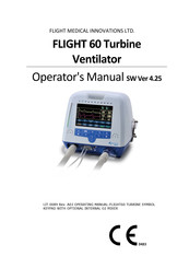
FLIGHT 60 Turbine
Ventilator
Operator’s Manual
SW Ver 4.25
LIT-0089 Rev. A03 OPERATING MANUAL-FLIGHT60 TURBINE SYMBOL
KEYPAD WITH OPTIONAL INTERNAL O2 MIXER
Related Manuals for Flight Medical Innovations FLIGHT 60
Summary of Contents for Flight Medical Innovations FLIGHT 60
-
Page 1
FLIGHT MEDICAL INNOVATIONS LTD. FLIGHT 60 Turbine Ventilator Operator’s Manual SW Ver 4.25 LIT-0089 Rev. A03 OPERATING MANUAL-FLIGHT60 TURBINE SYMBOL KEYPAD WITH OPTIONAL INTERNAL O2 MIXER… -
Page 3: W Arnings
When the FLIGHT 60 Ventilator is used in homecare, hospitals, EMS and sub- acute environments, only properly trained personnel should operate the ventilator. The FLIGHT 60 Ventilator is a restricted medical device designed for…
-
Page 4
FLIGHT MEDICAL due to such situations. Warranty The FLIGHT 60 Ventilator warranty does not apply for/ in case of: Defects caused by misuse, mishandling, tampering, or by modifications not authorized by FLIGHT MEDICAL or its representatives. -
Page 5
In no way does this or any of FLIGHT MEDICAL’s policies, training materials, guidelines, or instructions create an obligation for FLIGHT MEDICAL to perform any services. About this Document This document contains information intended to ensure safe and effective use of the FLIGHT 60 Ventilator. Chapter Name Contents Page 1… -
Page 6
Also includes contact information for technical support. 1 4 Ventilator Quick Describes the testing procedures. Pg. 14-1 Check Procedure 1 5 Technical Describes the technical specifications for: hardware, Pg. 15-1 Specifications safety, environmental and oxygen accessories. iv | Flight 60… -
Page 7: Table Of Contents
Table of Contents Table of Contents INTRODUCTION …………….. 1-1 …………….1-1 NTENDED ………………1-2 YMBOLS SAFETY INSTRUCTIONS …………..2-1 …………….. 2-1 ENERAL ARNINGS ………………2-4 AUTIONS VENTILATOR DESCRIPTION …………… 3-1 …………..3-1 RONT ANEL EATURES 3.1.1 Control Buttons …………..3-2 3.1.2 LED Indicators …………..
-
Page 8
ANDATORY ENTILATION SIMV M ) … 9-1 YNCHRONIZED NTERMITTENT ANDATORY ENTILATION 9.2.1 VC/PC/PRVC …………… 9-2 SPONT M ) ……….. 9-7 PONTANEOUS ENTILATION VG (V ) …………..9-7 OLUME UARANTEE B-LEV M ) ……….9-10 HASIC ENTILATION vi | Flight 60… -
Page 9
11 CLEANING AND MAINTENANCE …………11-1 11.1 C …………. 11-1 LEANING AND ISINFECTING 11.1.1 FLIGHT 60 Ventilator …………11-1 11.1.2 FLIGHT 60 Ventilator Accessories ……… 11-2 11.2 M …………….11-7 AINTENANCE 11.2.1 Preventive Maintenance …………11-7 11.2.2 O Sensor Maintenance …………11-8 11.2.3 Internal Battery Maintenance ………. -
Page 10
15.7 E …………15-8 NVIRONMENTAL PECIFICATIONS 15.8 I O2 M ……………. 15-9 NTERNAL IXER 15.9 O ……….. 15-9 XYGEN LENDING PECIFICATIONS 15.10 ……..15-10 XYGEN PECIFICATIONS 15.11 …….. 15-10 NTERNAL XYGEN ENSOR PECIFICATIONS 16 INDEX ……………….. 16-11 viii | Flight 60… -
Page 11: Introduction
O (–3 mbar) during emergency intake. The FLIGHT 60 Ventilator may be powered by external power (100-240 VAC or 12-15 VDC) or by its Li Ion internal batteries. Two internal Li Ion rechargeable batteries power the ventilator for up to 8 hours when fully charged.
-
Page 12: Symbols
Front Panel On/Off Alarm Reset OK (Enter) Decrease Button Increase Button Cancel Panel Lock Manual Breath Parameters Screen Extended Screen Technical Screen Nebulizer Port (optional) Rear Panel Caution; consult accompanying documents Type BF applied part Temperature limitation 1-2 | Flight 60…
-
Page 13
Introduction Symbol Description Humidity limitation Atmospheric pressure limitation DC – Direct Current AC – Alternating Current USB – Universal Serial Bus LAN – Local Area Network High Pressure (optional) and Low-Flow Oxygen Port MR unsafe – keep away from magnetic resonance imaging (MRI) equipment Operator’s Manual | 1-3… -
Page 15: Safety Instructions
Safety Instructions 2 Safety Instructions At all times, strictly follow this manual. The safe use of the FLIGHT 60 Ventilator requires full understanding of its operation, and adherence to the manual’s instructions. The equipment is only to be used for the purpose specified in Section …
-
Page 16
This depends on a number of factors including settings and usage patterns. When the FLIGHT 60 Ventilator is used for transport applications, ensure that the internal batteries are fully charged prior to use. -
Page 17
AC or DC power source. If the LED is not illuminated, check all power connections and resolve any problems. Always plug the FLIGHT 60 Ventilator into an AC power supply source when not in use, to ensure best battery performance. -
Page 18: Cautions
Only use medical grade oxygen with the high and low pressure ports. Do not place liquid containers in the immediate vicinity or on top of the FLIGHT 60 Ventilator. Liquids that get into the ventilator can cause equipment malfunction and damage.
-
Page 19
Batteries contain Li-Ion. Do not discard them in an incinerator or force them open. Batteries should not be disposed of with normal waste. Review FLIGHT 60 Ventilator Operator’s Manual before servicing the ventilator. Use the tools and equipment specified in this manual to perform specific procedures. -
Page 21: Ventilator Description
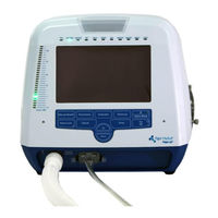
Ventilator Description 3 Ventilator Description Front Panel Features The front panel contains the control buttons, visual indicators, display screen, and patient circuit connection. Figure 1 – Front Panel Label Name Description Patient Circuit Connector Composed of a gas outlet and quick connector. +/- button Enables the user to adjust setting parameters.
-
Page 22: Control Buttons
Item Symbol Description 1 – Parameters The Parameters screen is the Flight 60’s default screen. (home) Display switches automatically to Parameters from the other screens if not operated for 30 seconds. Use the Parameters button to toggle between the numeric and the graphic displays.
-
Page 23: Led Indicators
Ventilator Description Item Symbol Description 3 – Panel Lock Enables the user to lock the ventilator’s control, preventing accidental changes. Pressing the button of a locked panel and then Enter, unlocks the panel. 4 – Cancel Enable the user to cancel parameters change. 5 –…
-
Page 24: Back Panel Features
AC Connector with Fuses 100 – 240 V AC, 50 – 60 Hz, Fuse 8A (time lag) DC Connector 12 – 15 V DC RS-232 Serial Port (COM2) Remote alarm connector (Normally Open and Normally Closed options). 3-4 | Flight 60…
-
Page 25: Left Side Panel Features
Ventilator Description Label Name Description RS-232 Serial Port (COM1) Online output of events and error messages to the PC, using a dedicated PCS2 protocol; for authorized and qualified service technicians only. USB B type PC connector: USB port for downloading the main application from the PC using a dedicated PCS2 protocol;…
-
Page 26: Right Side Panel Features
The Fresh Gas Intake also serves as the attachment socket for the optional FLIGHT 60 Ventilator Oxygen Blending Bag. Do not block the Fresh Gas Intake.
-
Page 27: Installation
Remove all of the items from the shipping box and inspect each part and component for completeness and verify that there is no shipping damage.. The complete assembly consists of the following parts: FLIGHT 60 Ventilator Operator’s Manual AC Power Cord Patient Circuit – Single Patient Use …
-
Page 28: Installing The Detachable And Integral Batteries
2. Plug the ventilator’s electric cord into a properly grounded outlet. The ventilator is now in STANDBY mode. The EXT PWR LED is illuminated, and the batteries begin recharging. Figure 7 – Plugging in the Power Cord 4-2 | Flight 60…
-
Page 29: Attaching The Patient Circuit
Installation Attaching the Patient Circuit The following procedure describes how to attach a patient circuit to the ventilator. To attach the single limb patient circuit: 1. Attach the quick connector to its socket on the front panel and tightly secure. 2.
-
Page 30: Circuit Test
7. Exhalation Valve Base Circuit Test Some disposable patient circuit/exhalation valve assemblies are not compatible with the FLIGHT 60 Ventilator due to the requirements of the ventilator’s pressure management system. If your disposable circuit fails consistently, switch to a FLIGHT MEDICAL approved patient circuit to ensure that…
-
Page 31: Connecting The Oxygen Supply
1. Connect an adult (500 ml) test lung with a 90 degree elbow to the Flow Sensor’s patient side or to the HME, if used. 2. Press the On/Off button once to place the Flight 60 into standby mode (the Flight 60 displays are on, but ventilation has not been initiated).
-
Page 32: Internal O Mixer
Changes in the pressure within the patient circuit may cause oxygen concentration to vary. Actual oxygen concentration varies with changes in flow in the patient circuit. The following control parameters may impact the oxygen concentration: Volume or Pressure settings PEEP settings 4-6 | Flight 60…
-
Page 33
Installation Frequency settings Peak Inspiratory Flow Flow Waveform I:E Ratio Leak Rate Low Pressure Oxygen Flow Rate When oxygen is administrated with a low flow source the actual delivered oxygen concentration will vary. Substantial leaks may reduce the inspired oxygen concentration. -
Page 35: Basic Operation
Review all of the General Warnings and Cautions in Chapter 2 prior to using the ventilator. The FLIGHT 60 Ventilator can be used either with an AC (external) or DC (internal batteries) power source. Before using the ventilator, either with AC or DC power source, ensure that the internal batteries are fully charged.
-
Page 36: Initiating Ventilation
3. Press the Silence button to mute the audible alarm. When operating with a battery, the ventilator turns itself off automatically after the system has been in SETTINGS mode for five minutes, and during this time no keys have been touched. 5-2 | Flight 60…
-
Page 37: Navigating Between Screens
Basic Operation Navigating Between Screens Navigation between screens is performed using the keypad buttons: Parameters, Extended, and Technical. Ventilation can be turned On and Off from the Parameters screen only. The following message is displayed while in the Extended or Technical screens: «…
-
Page 38: Default And Saved Values
(by a certified technician only); this means that stopping the device, turning it off, or disconnecting it from all power sources does not affect the parameter values. 5-4 | Flight 60…
-
Page 39: Ventilator Settings
Ventilator Settings 6 Ventilator Settings Home (Parameters) Screen This is the default screen in standby and ventilation mode. The display always switches back automatically to Parameters from the Extended or Technical settings display. Pressing the Parameters button switches over to the main settings screen.
-
Page 40
Description Ptrig The Flight 60 provides pressure or flow based triggering. Used to determine the pressure trigger level (trigger sensitivity) in terms of how far the airway pressure must drop below the set baseline pressure in order for a patient’s spontaneous efforts to be detected. -
Page 41
Ventilator Settings Button Description PS above Used to determine the level of support in pressure during inspiration, for patient triggered peep spontaneous breaths in SIMV, SPONT, MVG and B-LEVEL modes. During each spontaneous breath, the ventilator supports the patient by elevating the airway pressure to the PSV above peep + PEEP level. -
Page 42
P Low B-LEV control, used to set the low pressure baseline. Range: 0 to 40 cmH2O/mbar Resolution:1 cmH2O/mbar P High B-LEV control, used to set the high pressure baseline. Range: 3 to 60 cmH2O/mbar Resolution:1 cmH2O/mbar 6-4 | Flight 60… -
Page 43
Ventilator Settings Button Description T Low B-LEV control, used to set the low pressure baseline period. Range: 0.5 – 5.0 seconds Resolution: 0.1 second T High B-LEV control, used to set the high pressure baseline period. Range: 1 – 15.0 seconds Resolution: 0.5 second ALARMS Used to open the Alarms Screen… -
Page 44: Pop-Up Messages
HIGH MV reached LOW MV + 1. LOW MV is limited by HIGH MV LOW MV reached HIGH MV – 1. Max Ti reached Increasing VCV or Decreasing Flow caused Ti to reach its max possible value. 6-6 | Flight 60…
-
Page 45
Ventilator Settings Message Reason Min Ti reached Decreasing VCV or increasing Flow caused Ti to reach its min possible value. LOW O is limited by HIGH O LOW O reached HIGH O – 10. HIGH O is limited by LOW O HIGH O reached LOW O + 10. -
Page 46: Extended Screen
Pressing the Extended button switches over to the extended settings screen. Figure 14 – Extended Settings Button Description ON/OFF – Used to activate SIGH sub-mode of ventilation. SIGH Used to select the altitude compensation. Altitude Comp. Rate: 500-4500 m 6-8 | Flight 60…
-
Page 47
Ventilator Settings Button Description ON/OFF – Used to active non-invasive ventilation. ON/OFF/Clear – Used to active and clear trended data. Trends Factory Default: OFF Used to activate the MVG trigger delay function. Trigger Delay OFF: Trigger delay function is disabled. ON: Doubles the delay time before mandatory (time cycled) ventilation is activated. -
Page 48: Alarms Screen
Range: OFF, 1 to HIGH P Resolution:1 cmH O/mbar Low P=OFF is available after setting Low MV=0.0 HIGH P Used to set the maximum allowed pressure value of a mandatory breath. Range: LOW P to 99 cmH O/mbar Resolution:1 cmH O/mbar 6-10 | Flight 60…
-
Page 49: Technical Screen
Ventilator Settings Button Description LOW MV Used to set the minimum Minute Volume allowed for a patient. Range: 0.0 to High MV – 1 Resolution: 0.1 L Setting Low MVe=0.0 disables check circuit alarm HIGH MV Used to set the maximum Minute Volume allowed for a patient. Range: Low MV + 1.0 to 50 Resolution: 0.1 L FiO2 Low…
-
Page 50
Both the Alarm and the Change logs must be cleared following clock set. Used to display the alarms that have occurred, by date, time, and type. Show Log Alarm Alarm logs can be cleared by tapping the «Clear Log» button (passcode: 1315) 6-12 | Flight 60… -
Page 51
Ventilator Settings Button Description Used to display the changes that have been made to the ventilator states, modes, and Show Log settings. These changes are displayed by date, time, type, and values. Change Change logs can be cleared by tapping the «Clear Log» button (passcode: 1315). -
Page 53: Ventilator Alarms And Backup Ventilation
7 Ventilator Alarms and Backup Ventilation The FLIGHT 60 Ventilator comes with an intelligent alarm system, which warns you of problems with the ventilator. An alarm occurs when there is a risk to the patient. A caution occurs when there is an undesirable situation which does not pose immediate risk to the patient.
-
Page 54: Visual Alarm And Caution Signals
FAULT LED indicates unrecoverable internal system failure. Ventilate the patient with an alternate means of ventilation. Make note of the message in the alarm display area and the alarm log. Contact your provider or FLIGHT MEDICAL. 7-2 | Flight 60…
-
Page 55: Alarm And Caution Specifications
Ventilator Alarms and Backup Ventilation Alarm and Caution Specifications This section describes the specifications for the FLIGHT 60 Ventilator: Variable ventilation alarms Automatic ventilation alarms Automatic technical alarms Cautions 7.3.1 Variable Ventilation Alarms Alarm Priority Range…
-
Page 56: Automatic Ventilation Alarms
40%. O functions are disabled when the alarm is activated. This alarm is available with the optional internal O mixer model. VENTILATION WAS Medium When the ventilation is stopped (by user or accidentally) STOPPED 7-4 | Flight 60…
-
Page 57: Automatic Technical Alarms
Ventilator Alarms and Backup Ventilation Alarm Priority Activation CHECK O2 LEAK Medium When the O2 Leak sensor value is out of range SENSOR High See section 7.5 Disconnection high High When disconnection in the exhalation limb is detected leak 7.3.3 Automatic Technical Alarms Alarm Priority…
-
Page 58: Cautions (Low Priority)
SEC. BAT TEMP When the integral (secondary) battery HIGH temperature is higher than 60 °C. When an alarm message is generated, it is recorded in the alarms log with its accurate time and date. 7.3.4 Cautions (Low Priority) 7-6 | Flight 60…
-
Page 59: Apnea Backup Ventilation
When Customize BUV is enable Apnea Backup Ventilation Flight 60 provides apnea backup ventilation when no inspiratory efforts are detected or control breaths are delivered for the set Apnea Interval (see Apnea Interval settings in Section 6 .3 Alarms Screen).
-
Page 60: Backup Ventilation In Acmv And Simv Modes
To store a preset Customize BUV: On the ventilator front panel, press the Technical button. The Technical parameters are displayed on the ventilator screen. Tap the Set Save control button and enter the 1315 access code. 7-8 | Flight 60…
-
Page 61: Low Power Ventilation (Lpv)
“Customized BUV is Active” caution appears after enabling Customized BUV. Low Power Ventilation (LPV) Flight 60 Turbine provides a low power mode of ventilation (LPV). LPV is activated in either one of the following cases: External power cord and detachable battery are disconnected…
-
Page 62: Silencing Audible Alarms
Ventilator Alarms and Backup Ventilation When LPV ventilation is active immediately connect the FLIGHT 60 Ventilator to external AC or DC power. Pressing the Alarm Reset button to stop the LPV alarm does not revert the ventilation mode to the one active prior to the alarm.
-
Page 63: Disabling The Low P Alarm
Ventilator Alarms and Backup Ventilation default. In order to disable the Check Circuit alarm, set the Low MV alarm to 0.0. The following pop-up message will appear: «Setting Low MV alarm to 0.0 disables Check Circuit alarm» The message will automatically disappear in 5 seconds. To accept the new Low MV value of 0.0, press the ENTER button or tap the Low MV button.
-
Page 64: Setting Up A Remote Alarm
Other conditions, such as system shutdown (or power down) can also be detected by the remote alarm system. The FLIGHT 60 device can be connected to a third party remote alarm system in several configurations. In order to connect the device to a remote alarm system, a special cable must be fitted to the system and integration must be conducted between the device and the remote alarm system.
-
Page 65: Monitoring
Graphic Display The Flight 60 displays pressure and flow waveforms by default. By tapping the monitoring area a volume waveform will replace the flow waveform. An additional tap on the screen will result in waveforms being replaced by loops.
-
Page 66: Trends
Monitoring The Flight 60 can display a dynamic loop based on the following parameter combinations: Pressure/Volume Flow/Volume Tap the monitoring area to toggle between the three different graphic displays: Flow, Volume and Loops. Real-time waveforms and loops ranges:…
-
Page 67: Selecting Trended Parameters
The ventilator uses an auto-scaling function – scales of each trended parameter may differ based on the actual range of values to be displayed. Lung Mechanics Monitoring Display The following lung mechanics monitoring parameters can be measured with the Flight 60: Operator’s Manual | 8-3…
-
Page 68
1 second to 6 seconds (factory default = 3 seconds). 8.2.1 Lung Mechanics Monitoring Display Lung mechanics display is located on the main monitoring area of the screen and is displayed automatically for 10 seconds. 8-4 | Flight 60… -
Page 69: Rsbi Monitoring
RSBI is the actual rate divided by the exhaled tidal volume [1/min*L]. Additional monitoring parameters display The default Flight 60 numeric display located on the right side of the screen shows the basic numeric display (Actual rate, PIP, MVE, FiO , Vti and Vte).
-
Page 70: Numeric Display
Monitoring Numeric Display The Flight 60 default display is graphic. Use the Parameters button to toggle between the numeric and the graphic displays. The following table describes the patient monitoring parameters. Name Description Range Resolution Updated Peak Inspiratory Pressure 0 to 99 cmH…
-
Page 71: Ventilation Modes
Ti, patient respiratory mechanics in Pressure Control, and by the tidal volume setting in Volume Control. As with all FLIGHT 60 Ventilator operating modes, Backup Ventilation is activated if the Apnea alarm limit is violated.
-
Page 72: Vc/Pc/Prvc
60 seconds, to the Rate (b/min) setting. As with all FLIGHT 60 Ventilator operating modes, Backup Ventilation is activated if the Apnea alarm limit is violated. Figure 18 – Synchronized Intermittent Mandatory Ventilation (SIMV) 9.2.1…
-
Page 73
Ventilation Modes Make sure that the mandatory flow setting is adequate to meet patient flow demands. In ACMV VC mode, the Rise Profile control button is not utilized and is therefore darkened. However, it remains adjustable. The VC mode delivers volume controlled breaths as the mandatory breaths. The user can set the volume and select whether the Ti or the Flow will adjust to fit the set volume. -
Page 74
2. Adjust the VT value (tidal volume), using the +/- button. 9.2.1.2 Pressure Control Ventilation (PC) The FLIGHT 60 Ventilator targets and maintains patient airway pressure at the set pressure control level throughout inspiration. Breath termination occurs when either of the following conditions exists: … -
Page 75
Ventilation Modes When disconnecting the patient circuit during PC/PS ventilation, such as for suctioning, the flow may increase in order to compensate for the low pressure. After reconnecting the patient circuit, the flow automatically readjusts to meet the patient’s demand. The PC mode delivers pressure controlled breaths as the mandatory breaths. -
Page 76
Pressure and volume limits should be set in PRVC to prevent unintentional pressure and volume changes. To set the PRVC sub mode of operation: 1. Tap the sub-modes control button. The PC, VC and PRVC sub-modes are displayed. 9-6 | Flight 60… -
Page 77: Spont Mode (Spontaneous Ventilation)
Entries for tidal volume, Rate and Ti are all inactive in SPONT mode. However, users can preset these parameters for future ACMV or SIMV operation. As with all FLIGHT 60 Ventilator operating modes, Backup Ventilation is activated if the Apnea alarm limit is violated.
-
Page 78
The total time for a mandatory breath to be triggered will equal twice the “OFF” time. To avoid low rate due to intermittent spontaneous patient efforts, the Flight 60 automatically deactivates the trigger delay when the actual rate is lower than the set rate. 9-8 | Flight 60… -
Page 79
Ventilation Modes To set the Trigger Delay: 1. On the ventilator front panel, press the Extended button. 2. Tap the Trigger Delay control button. The control button turns orange, and a pop-up list displays two options: ON and OFF. 3. To activate Trigger Delay, tap the control button to select ON; to deactivate the Trigger Delay, tap the control button to select OFF. -
Page 80: B-Lev Mode (Bi-Phasic Ventilation)
P low – the low pressure baseline. P high – the high pressure baseline. T low – the low pressure baseline period. T high – the high pressure baseline period. PS above peep – the pressure support level. 9-10 | Flight 60…
-
Page 81: Niv (Non-Invasive Ventilation) Sub Mode Auto-Alarm Function
Ventilation Modes NIV (Non-Invasive Ventilation) Sub Mode Auto-Alarm Function Flight 60 Turbine provides auto-leak compensation up to 60L/min in all modes of ventilation. When NIV auto-alarm function is set to ON the following alarms are disabled: Check Circuit Low MV…
-
Page 83: Special Functions
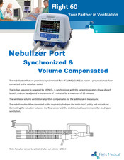
Error! Reference source not found. 10 Special Functions 10.1 Nebulizer (OPTIONAL) The nebulizer feature provides a synchronized flow of 7LPM (±1LPM) to power a pneumatic nebulizer connected to the nebulizer outlet. The in-line nebulizer is powered by 100% O2 and synchronized with the patient inspiratory phase of each breath and can be adjusted in increments of 5 minutes for maximum of 60 minutes.
-
Page 84: Minutes 100% O2 (Optional)
The sigh feature is available in volume ventilation modes only. To set SIGH: 1. On the ventilator front panel, press the Extended button. 2. Tap the SIGH control button. The control button turns orange, and a pop-up list displays two options: ON and OFF. 10-2 | Flight 60…
-
Page 85: Manual Breath
Error! Reference source not found. Figure 27 – SIGH Sub-modes 3. To activate SIGH, tap the control button to select ON; to deactivate the SIGH, tap the control button to select OFF. 4. Press the OK (Enter) button to confirm your selection. Your selection (ON or OFF) is displayed on the control button.
-
Page 86: Quick-Start And Preset Ventilation Configurations
Pediatric: choose to load preset #2 labeled “Pediatric” SPONT (CPAP): choose to load preset #3 labeled “SPONT (CPAP)” Press the OK button to confirm preset selection. Always make sure control parameters and alarm limits are appropriately set before starting ventilation. 10-4 | Flight 60…
-
Page 87: Quick-Start: Factory Default Settings
Error! Reference source not found. 10.6.1 Quick-Start: Factory default settings The table below shows the factory default control setting for the Adult, Pediatric and SPONT configurations presets. Parameter Adult Pediatric SPONT/CPAP (preset #1) (preset #2) (Preset #3) Mode SIMV-VC SIMV-PC SPONT Rate PEEP…
-
Page 88: I N -Use O 2 Sensor Calibration
10.7 In-Use O Sensor Calibration In-use calibration is available for both internal and external O2 mixer Flight 60 models, please follow the on-screen instructions. In-use calibration should only be performed on clinically stable and synchronized patients. If any alarm is being activated, the calibration procedure must be aborted.
-
Page 89
Error! Reference source not found. 2. A single point calibration at 100% oxygen concentration 3. A single point calibration at 21% oxygen concentration In-use calibration can be performed while patient’s ventilation continues. Please consider the changes in oxygen delivery while calibration in on going before performing in-use calibration. -
Page 90: Altitude Compensation
Press the OK (Enter) button to confirm your selection. 10.8 Altitude Compensation The Flight 60 ventilator automatically maintains precise volume delivery in altitudes up to 15,000 feet (4,500 meters). The manual altitude adjustment is only for the flow and volume accuracy measured by the proximal flow sensor.
-
Page 91: Cleaning And Maintenance
Homecare Dealer instructions. 11.1.1 FLIGHT 60 Ventilator Wipe clean the FLIGHT 60 Ventilator between patients, and once a week while in use. To clean the ventilator: 1. Wipe clean the exterior (besides the screen) of the ventilator and all parts not in direct contact with patients, using a cloth that has been dampened with a medical detergent or alcohol-based cleaning solution.
-
Page 92: Flight 60 Ventilator Accessories
Cleaning and Maintenance 11.1.2 FLIGHT 60 Ventilator Accessories All accessories should be thoroughly cleaned, rinsed, and air dried prior to disinfecting. Examine all accessories for excessive wear or damage. Discard and replace if necessary. 11.1.2.1 Reusable (Single Patient) Patient Circuits The patient circuit includes 22mm ID breathing tube, exhalation valve and flow sensing kit (flow orifice, quick connector and triplet 2.75mm ID tubes).
-
Page 93
Cleaning and Maintenance To clean the patient circuit: 1. Use a low flow of running water or air to clear tubing and passages of organic matter. 2. Bathe for a minimum of 10 minutes using mild detergent or liquid cleanser. 3. -
Page 94
1. Remove the exhalation valve from the patient circuit (see Figure 29). 2. Rotate counterclockwise the top cap of the exhalation valve and lift it off. 3. Lift out the valve drive line fitting, and separate it from the diaphragm (see Figure 30). 11-4 | Flight 60… -
Page 95
Cleaning and Maintenance Figure 30 – Exhalation Valve Disassembled Parts To clean the exhalation valve: 1. Use a low flow of running water or air to clear tubing and passages of organic matter. 2. Wash the exhalation valve with a soft brush. 3. -
Page 96
This manual can only provide general guidelines for cleaning and disinfecting. It is the user’s responsibility to ensure the validity and effectiveness of the methods used. 11-6 | Flight 60… -
Page 97: Maintenance
11.2 Maintenance 11.2.1 Preventive Maintenance It is recommended to take the following measures to maintain the FLIGHT 60 Ventilator: Check the Air Inlet Filter (located behind the Filter Cover) weekly. Replace it when the majority of the filter surface area has changed from a clean white to dirty brown color.
-
Page 98: Internal Battery Maintenance
NEVER reverse the inlet particle filter when it is dirty. Inspect the FLIGHT 60 Ventilator power cord on a regular basis, for signs of a broken or frayed power cord. Inspect the exhalation valve and flow orifice to verify that there are no cracks or damaged surfaces.
-
Page 99: General Warnings
Cleaning and Maintenance 11.3 General Warnings Preventive maintenance work, repairs, and service may only be performed by FLIGHT MEDICAL trained or factory-authorized personnel. Always follow accepted hospital procedures or physician instructions for handling equipment contaminated with body fluids. …
-
Page 101: Troubleshooting
The following practical troubleshooting section is provided as a training resource for individuals learning how to use the FLIGHT 60 Ventilator, and as a reference tool for those already familiar with its use and operation. It should be noted that this outline is not all inclusive, and is intended only as a guide.
-
Page 102
Pressure transducer is improperly Call FLIGHT MEDICAL. calibrated or defective. Empty Battery Alarm Detachable and Integral batteries charge Immediately connect the FLIGHT 60 is depleted and the ventilator shutdown Ventilator to external AC or DC will occur shortly. power. Power Switch Over External power cord is disconnected. -
Page 103
Contact Information Problem Potential Cause Suggested Action High MV alarm Increased spontaneous patient Evaluate the patient. Adjust the High breathing. MV alarm setting, if needed. Increase in trachea/airway leak. Evaluate the leak, look for normal wake-sleep trends, and set alarms appropriately. -
Page 104
Check all patient circuit Alarm connections. Target pressure setting requires a flow Reevaluate the ventilator settings rate that is beyond the FLIGHT 60 and strategy. Ventilator’s maximal flow capability. Fault Alarm Led Unrecoverable internal system failure. Ventilate the patient with an alternate means of ventilation. -
Page 105: General/Clinical
Contact Information 12.3 General/Clinical Problem Potential Cause Suggested Action Alarm volume too Unintended setting. To toggle between loud and quiet, push loud or too quiet. the buzzer button and choose from the list. Batteries Batteries are not fully charged. Charge the batteries to their full charge depleted too fast;…
-
Page 106
Exhalation valve in use is not Use an exhalation valve that is approved compatible with ventilator. for use with the FLIGHT 60 Ventilator. Low compliance / high resistance of Make sure that the patient circuit is 22 Exhalation Valve circuit system. -
Page 107
Contact Information Problem Potential Cause Suggested Action High Pressure alarm setting reached If a higher inflation pressure is needed, Manual Inflation during Manual inflation. increase the High Pressure alarm limit Button setting to a safe but appropriate level. Breath terminates Otherwise, decrease the flow rate or and High manual inflation time. -
Page 108
Pressure support is set too low for Reevaluate the pressure support setting. patient need. Monitored Tidal Circuit disconnect Check Circuit Connections Volume Quick Connect not firmly attached Re-attach the Quick Connector Vte and Vti inconsistent 12-8 | Flight 60… -
Page 109: Oxygen Enrichment
Noise When that it is not empty. Air/Oxygen Mixer Is Connected. Ventilator Pistons The FLIGHT 60 Ventilator generates a Ventilator is operating correctly. Move Between 7.5 L/min of continuous flow in between breaths when PEEP is > 0 cmH Breaths…
-
Page 110: Contact Information
7 Hatnufa St., Petach Tikva 4951025, ISRAEL Tel: +972-3-673-1660 Fax: +972-3-673-1690 Email: info@flight-medical.com Website: www.flight-medical.com European Authorized Representative Obeliss.a Address: Boulevard Général Wahis 53 1030 Brussels, BELGIUM Tel: +32 2 7325954 Fax: +32 2 7326003 Email: mail@obelis.net 13-10 | Flight 60…
-
Page 111: Ventilator Quick Check Procedure
FLIGHT 60 Ventilator, to verify proper operation. It can also be performed in the homecare environment to ensure proper setup and function of the ventilator. Do not use the FLIGHT 60 Ventilator if it fails this procedure. 14.1.1 Setting Up the Ventilator for the Test Before performing the test, do the following: …
-
Page 112: Quick Check Procedure
Ventilator Quick Check Procedure 3. Connect a patient circuit with 500 ml test lung, to the FLIGHT 60 Ventilator. 4. Calibrate the exhalation valve. See Section 4 .7. 5. Press the On/Off button once. The ventilator performs a brief self-test and enters SETTINGS mode.
-
Page 113: Checking The Alarms
Ventilator Quick Check Procedure 14.2.2 Checking the Alarms To check for High Pressure alarm: 1. Set the High P alarm limit to 10 cmH 2. Verify that High Pressure alarm is activated (HIGH PRESSURE message display, visual and audible alarm and the indicator LED turns on). 3.
-
Page 114: Check-Off Sheet
Ventilator Quick Check Procedure 14.3 Check-Off Sheet FLIGHT 60 Ventilator Quick Check Pass/Fail Check-Off Sheet Preparation for Use Tests Indicate Result for each Test Pretest Inspection Check Pass _____ Fail ______ 1. Power Management Check Pass _____ Fail ______ Power Switchover Caution…
-
Page 115: Technical Specifications
Technical Specifications 15 Technical Specifications 15.1 Physical Specifications Physical Characteristic Specification Ventilator Weight 5.0Kg/5.5Kg (with internal blender) 11.641 in wide x 11.457/13.071 in deep (SL/DL) x 9.803 in high. Ventilator Dimensions 295 mm wide x 291/332 mm deep (SL/DL) x 249 mm high. Reusable Single Patient Circuit Reusable (single patient) 22 mm ID 180 cm.
-
Page 116
CISPR 11 all establishments, Harmonic emissions Class A including domestic IEC 61000-3-2 establishment and Voltage fluctuations/Flicker Complies those directly emissions connected to the public low-voltage IEC 61000-3-3 power supply network that supplies building used for domestic purpose. 15-2 | Flight 60… -
Page 117
Technical Specifications Immunity test IEC60601 Test Compliance Electromagnetic level Level Environment Guidance Electromagnetic ±6 kV contact ±8 kV contact The relative Discharge (ESD) humidity should be at least 5 % IEC 61000-4-2 ±8 kV air ±15 kV air Electrical fast ±2 kV for power ±2 kV for supply Main power quality… -
Page 118
Field strengths from fixed RF transmitters, as determined 20, cat.R by an electromagnetic site survey , should be less than the compliance level in each frequency range Interference may occur in the vicinity of equipment marked with the following symbol: 15-4 | Flight 60… -
Page 119: Recommended Separation Distance Between Portable Mobile Rf Communications Equipment And The Device
Technical Specifications NOTE A: At 80 MHz, 400 MHz, and 800 MHz, the higher frequency range applies. NOTE B: These guidelines may not apply in all situations. Electromagnetic propagation is affected by absorption and reflection from structure, object, and people. Field strength from fixed transmitters, such as base stations for radio (cellular/cordless) telephones and land mobile radios, amateur radio, AM and FM radio broadcast and TV broadcast cannot be predicted theoretically with…
-
Page 120: Recommended Separation Distances Between Power Buses And The Product
30A/m 1000 15.3.3 EMC statement of Essential Performance This statement is the basis of the immunity pass/fail criteria for the EMC tests. The essential performance is: 1. There will be no cessation of ventilation 15-6 | Flight 60…
-
Page 121: Electrical Specifications
Technical Specifications 2. There will be no interruption of power supply Cables The AC cable maximum length should be 3 meters. The device should not be used adjacent to or stacked with other equipment. If adjacent or stacked use is necessary, the device should be observed to verify normal operation in the configuration in which it will be used…
-
Page 122: Safety And Particular Standard Specifications
C to 50 C / -.4 F to 122 Storage Temperature C to 60 C / -5.8 F to 160 Operating Pressure (Altitude) 70 KpA to 110 KpA, up to 15,000ft Humidity 15% to 95% RH at 31 15-8 | Flight 60…
-
Page 123: Internal O2 Mixer
Technical Specifications Condition Range Water Resistance IP34 (splash proof) IEC 60529 Sinusoidal Vibrations IEC 60068-2-6 Bump IEC 68-2-29 Free Fall IEC 60068-2-32 Random Vibrations Wide Band IEC 60068-2-6 15.8 Internal O2 Mixer Feature Specification Connector Type DISS Input Pressure – Oxygen 35-90 psig/240-620 kPa 21% to 100% Accuracy…
-
Page 124: Low Flow Port Oxygen Specifications
Less than 13 seconds Accuracy +/- 2% Manufacturer: Flight Medical Innovations Ltd. Hatnufa St. 7 4951025 Petach Tikva Israel Tel: +972 3 6731660 EC Representative: Obelis S.A. Bd Gal Wahis 531030 Brussels Belgium TEL: +32-2-7325954 FAX: +32-2-732-6003 15-10 | Flight 60…
-
Page 125: Index
Index 16 Index PROX LINE Resetting 7-10 Sec BAT V. GAUGE AC connector Sec BAT V. HIGH Accessories 11-2 Sec BAT V. LOW ACMV Setting remote alarm 7-12 ACMV mode Silencing 7-10 Actual f Target Volume Not Reached Actual rate 8-1, 8-6 Variable ventilation Air inlet particle filter…
-
Page 126
Electrical specifications 15-7 Alarms 14-3 Emergency air intake Low pressure alarm 14-3 EMPTY BAT Monitored parameters 14-3 Empty battery alarm 12-2 Checking power management 14-2 Environmental specifications 15-8 Circuit disconnect 12-5 Exhalation circuit test fails 12-6 16-12 | Flight 60… -
Page 127
Index Exhalation valve High Pressure O Port (optional) Cleaning 11-5 HIGH Rate 6-10 Disinfect 11-5 High value of oxygen 6-11 Reassembling 11-5 Hold Length 6-9, 6-13 Exhalation valve base Home button Exhalation valve cover Home screen Exhalation valve diaphragm Hour meter 6-12 Exhalation valve honks 12-6… -
Page 128
9-2, 9-4, 9-6 Nebulizer 6-5, 10-1 PCV above peep Network logging PCV not reached alarm 12-4 Next service 6-12 Peak inspiratory flow Peak inspiratory pressure 8-1, 8-6 Non invasive ventilation 9-11 PEEP NPPV 9-11 PEEP control 12-7 16-14 | Flight 60… -
Page 129
Index Peripherals connector Cautions Physical specifications 15-1 General warnings Safety specifications 15-8 Plateau Pressure Sec Bat Only! Plugging in power cord Sec BAT V. GAUGE Pneumatic Specifications 15-1 Sec BAT V. HIGH Positive airway pressure Sec BAT V. LOW POWER FAULT Set Clock 6-12 Power management… -
Page 130
Low Pbase alarm 12-3 Low pressure alarm 12-3 Manual inflation button 12-7 Water in breathing circuit tubing 12-9 monitored tidal volume 12-8 Waveform Occlusion alarm 12-4 Weight of ventilator 15-1 pcvnot reached alarm 12-4 PEEP control 12-7 16-16 | Flight 60…
This manual is also suitable for:
60
Особенности ИВЛ Flight 60
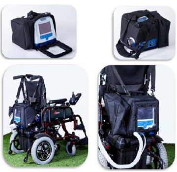
 Конструкция аппарата Flight 60, его габариты и дизайн обеспечивают возможность его комфортного применения, как для пациентов, так и для персонала в палате интенсивной терапии, в палате послеоперационного пробуждения, при внутрибольничном перемещении пациентов, в машинах скорой помощи и в других нестандартных ситуациях.
Режимы вентиляции
1. Вентиляция с гарантированным объемом
Это вентиляция с контролем по давлению с доставкой гарантированного объема воздуха пациенту.
Целевой дыхательный объем или минутный объем устанавливается врачом, Flight 60 доставляет заданный целевой объем или минутный объем путем регулирования давления в режиме PCV. Аппарат будет использовать минимальное возможное давление, чтобы доставить гарантированный дыхательный или минутный объем.
Возможны два вида вентиляции с гарантированным объемом:
- VTG – Гарантия дыхательного объема
- MVG – Гарантия минутного объема
2. VTG (Гарантированный дыхательного объема)
В режиме VTG, целевой объем достигается посредством регулирования поддержки давлением, применяемым к пациенту на основании трех параметров настройки:
- Требуемый VTG – Целевой дыхательный объем.
- Pмин – минимальное давление (установленное врачом)
- Pмакс – максимальное давление (установленное врачом)
3. MVG (Гарантированный минутный объем)
В режиме MVG, когда отсутствует спонтанное дыхание в интервале, определяемом установленной частотой дыхания, аппарат начинает принудительное дыхание с установленным временем вдоха. В сочетании с установленным VTG определяется минимальный минутный объем.
Настройки параметров, которые требуются для режима MVG:
- Целевой VTG – Целевой дыхательный объем
- Pмин – минимальное давление (установленное врачом)
Базовая комплектация
| Аппарат Flight 60 | 1 шт. |
|---|---|
| Гофрированная трубка (шланг) | 1 шт. |
| Маска для вентиляции (подарок!) | 1 шт. |
| Инструкции по эксплуатации для пользователя | 1 шт. |
| Гарантийный талон | 1 шт. |
В зависимости от требований к терапии, в некоторых случаях используются дополнительные аксессуары:
- Смеситель воздуха/кислорода
- Смесительный мешок
Преимущества и характеристики ИВЛ
- 7″ цветной сенсорный экран
- Очень легкий и портативный – 6,3 кг
- Встроенная батарея на 12 часов работы с возможностью быстрой замены без отключения аппарата
- Встроенный компрессор – не требует подвода сжатого воздуха
- Все современные режимы вентиляции по давлению и объему, инвазивная и неинвазивная вентиляция легких
- Вентиляция легких для детей и взрослых
- Диапазон дыхательного объема от 30 мл. до 2.2 литров в режиме VCV и 5-60 см H2O в режиме PSV
- Снижение нижнего предела установки дыхательного объема
- Многоуровневая система сигналов тревоги
- Возможность управления профилем скорости потока и профилем нарастания давления в режиме PСV
- Расширенный диапазон выбора и проведения режимов впомогательной вентиляции
- Датчики потока и давления
- Встроенный кислородный датчик
- Возможность подключения к источнику кислорода с низкими и высоким давлением(3-6 атм.)
Видео-обзор
Аппарат Flight 60 это надежность и неприхотливость, возможность работы от встроенных батарей до 12 часов, оптимальный набор режимов вентиляции и развитая система тревог. Flight 60 предлагает вам прекрасную производительность, объединенную с легким, интуитивно понятным интерфейсом.
Многочисленные функции позволяют этому аппарату по праву потеснить ряд многих более «солидных» и дорогих аппаратов не только в транспортном и неотложном применении, но и в палатах реанимации и интенсивной терапии больниц и клиник.
К числу дополнительных, но немаловажных возможностей аппарата Flight 60 следует отнести:
- Вентиляция пациентов разных категорий – взрослых и детей от 5 кг.
- Вентиляция по объёму (VCV) от 30 до 2200 мл
- Вентиляция по давлению (PCV) от 5 до 80 см.вод.ст
- Удобные в использовании журнал событий и журнал тревог
- Многоуровневая система тревог
- Работа как с источником высокого давления кислорода (2,4-6,2 бар.), так и с концентратором кислорода, а так же вентиляция окружающим воздухом для краткосрочной вентиляции в чрезвычайных ситуациях
- Блокировка клавиатуры от случайного изменения параметров вентиляции
- Простой и интуитивно понятный интерфейс
- Сенсорный дисплей
- Управление профилем нарастания давления при режиме PSV и профилем скорости потока
- Расширенный диапазон выбора и проведения режимов вспомогательной вентиляции
- Сохранение до 5 предустановленных настроек, под разные категории пациентов
- Установка паузы на вдохе или на выдохе
Конструкция аппарата Flight 60, его габариты, дизайн, интуитивно понятный интерфейс, обеспечивают возможность его комфортного применения как для пациентов, так и для персонала в палате интенсивной терапии, в палате послеоперационного пробуждения, при внутрибольничном перемещении пациентов, в машинах скорой помощи и в других нестандартных ситуациях.


Вентиляция с гарантированным объемом
Это вентиляция с контролем по давлению с доставкой гарантированного объема пациенту.
Целевой дыхательный объем или минутный объем устанавливается врачом, Flight 60 доставляет заданный целевой объем или минутный объем. Аппарат будет использовать минимальное возможное давление, чтобы доставить гарантированный дыхательный или минутный объем.
Возможны два вида вентиляции с гарантированным объемом:
- VTG – Гарантия дыхательного объема
- MVG – Гарантия минутного объема
VTG (Гарантия дыхательного объема)
В режиме VTG, целевой объем достигается посредством регулирования поддержки давлением, приложенное к пациенту на основании трех параметров настройки:
- Требуемый VTG — Целевой дыхательный объем
- PSVмин — минимальное давление (установленное врачом)
- PSVмакс — максимальное давление (установленное врачом).
MVG (Гарантированный минутный объем)
В режиме MVG, когда пациент не совершает попыток дыхания в интервале, определяемом установленной частотой дыхания, аппарат начинает принудительное дыхание с установленным Ti (временем вдоха), в сочетании с установленным целевым VTG, определяя минимальный минутный объем.
Настройки параметров, которые требуются для режима MVG:
- Целевой VTG — Целевой дыхательный объем
- PSVмин — минимальное давление (установленное врачом)
- PSVмакс — максимальное давление (установленное врачом).
Расширенная система мониторинга параметров:
- Мониторинг реальных показателей: дыхательного объёма и давления, частоты вентиляции и содержания кислорода в дыхательной смеси
- Мониторинг графиков, петель и трендов, по выбору врача
Аппарат ИВЛ Flight 60 с встроенным компрессором, аккумуляторная батарея на 12 часов работы, O2 смесителем и небулайзером.
Основные характеристики аппарата ИВЛ Flight 60:
7″ цветной сенсорный экран
12 часовая встроенная батарея с возможностью горячей замены без отключения аппарата
встроенный компрессор — не требует подвода сжатого воздуха
все современные режимы вентиляции по давлению и объему, инвазивная и неинвазивная вентиляция легких
детская и взорослая вентиляция диапазон дыхательного объема от 30 мл. до 2.2 литров
датчики потока и давления
встроенный кислородный датчик
возможность подключения к источнику кислорода с низким и высоким давлением
Подробные технические характеристики аппарата ИВЛ Flight 60:
|
№ |
Технические характеристики |
Значение |
|
Контингент пациентов |
Дети от 5 кг и взрослые |
|
|
Область применения |
ИВЛ в отделениях реанимации, палатах пробуждения, обеспечение ИВЛ при оперативных вмешательствах и процедурах под внутривенной анестезией, ИВЛ при транспортировке пациентов как в условиях внутрибольничных перевозок так и в условиях скорой помощи, домашняя вентиляция |
|
|
Технические характеристики |
||
|
Размеры: ширина х глубина х высота |
290х280 х250 мм |
|
|
Вес нетто (без тележки) |
6,3 кг |
|
|
Электропитание |
||
|
Переменный ток |
100-240 в/ 50 — 60 Гц |
|
|
Возможность работы от наружного источника постоянного тока с напряжением 12 — 30В |
12 — 30 Вольт |
|
|
Время работы от встроенной батареи |
Не менее 12 часов |
|
|
Время зарядки батареи |
Не более 3 часов |
|
|
Привод и пневматическая схема |
||
|
Электропривод |
Электропривод — встроенный высокопроизводительный, бесшумный (шум 45 Дцб) двухпистонный компрессор, обеспечивающий быстрое изменение скорости инспираторного потока в ответ на респираторные потребности пациента |
|
|
Уровень шума |
Не более 45 Дцб |
|
|
Клапан выдоха |
Активного типа. Активный клапан выдоха обеспечивает свободное дыхание пациента во время принудительных дыхательных циклов |
|
|
Тип управления клапаном выдоха |
Электромагнитный пропорциональный клапан с микропроцессорным контролем |
|
|
Проксимальные датчики потока (детский и взрослый) |
Тип датчика — пневмотахометрический |
|
|
Возможность использования контура пациента с магистралями вдоха и выдоха и с одной магистралью и клапаном выдоха |
Соответствие |
|
|
18 |
Синхронизированный встроенный небулайзер |
Наличие |
|
19 |
Встроенный электронный миксер |
Наличие |
|
20 |
Калибровка датчика О2 без прерывания вентиляции |
Наличие |
|
Подключение кислорода |
||
|
От централизованной системы газоснабжения 2,4 — 6,2 бар |
Наличие |
|
|
От источника кислорода низкого давления |
Наличие |
|
|
Пользовательский интерфейс |
||
|
Панель управления с активным цветным дисплеем для индикации настроек и параметров вентиляции, графиков, тревожных сообщений и кнопками управления. Трехступенчатая схема изменения параметров вентиляции: активация, изменение, подтверждение. |
Наличие |
|
|
Размер и тип дисплея |
TFT, цветной, (диагональ не менее 7 дюймов) с функцией Touch Screen |
|
|
27 |
Размер и тип дополнительного дисплея |
Планшетный компьютер, экран цветной, сенсорный, с поддержкой Multitouch, диагональ 13,3 дюйма |
|
Русифицированное программное обеспечение |
Наличие |
|
|
Наличие режима Standby |
Режим ожидания с возможностью изменения параметров и сохранением данных |
|
|
Режим самопроверки после включения аппарата |
Наличие |
|
|
Тест дыхательного контура |
Наличие |
|
|
Выбор единиц измерения параметров давления |
см.вод.ст. или мбар |
|
|
Режим экономии энергии |
При режиме экономии энергии монитор отключается, сохраняется световая индикация барографического монитора давления |
|
|
Сохранение в памяти установленных ранее настройками вентиляции не менее, чем для 5 пациентов |
Наличие |
|
|
Старт вентиляции по выбору одной из 5 ранее введенных настроек вентиляции |
Наличие |
|
|
Автоматический старт вентиляции с последними настройками режима и параметров |
Наличие |
|
|
Журнал тревог |
Регистрация тревог по дате , времени и типу |
|
|
Журнал событий |
Регистрация изменения параметров вентиляции по дате, времени и типу не менее 1000 событий |
|
|
Выбор режимов ИВЛ с помощью индивидуальных клавиш на панели управления вентилятора |
Наличие |
|
|
Индикатор спонтанного дыхания пациента |
Наличие |
|
|
29 сегментный барогафический дисплей давления |
От –10 до 120 мбаp |
|
|
Передача данных параметров ИВЛ в информационную систему клиники |
Наличие |
|
|
Управление |
||
|
Режимы вентиляции |
АCMV, SIMV, Spon., (BiPAP/CPAP) Volume Guarantee (VG), Ручная, Back Up Ventilation, NPPV (неинвазивная вентиляция) |
|
|
Типы дыхания |
PCV, PSV, VCV (Ti/Flow — c настройкой времени вдоха или потока по выбору) |
|
|
NPPV |
неинвазивная вентиляция c компенсацией утечек не менее 30 л/мин) |
|
|
VG Mode |
VGt (Гарантированный объем), VMG (Минутный гарантированный объем |
|
|
Sigh (раздувание) |
включено/выключено |
|
|
Vt — Дыхательный объем |
30 мл — 2,2 л +/- 10 % |
|
|
F — частота дыхания |
1-99 дых/мин |
|
|
Ti — время вдоха |
0,1 — 3,0 сек |
|
|
Flow — регулируемый поток |
2- 100 л/мин |
|
|
PC -Максимальное давление на вдохе |
5-60 H2O/мбар |
|
|
P — поддержка давлением |
0-60 H2O/мбар |
|
|
PEEP/CPAP |
3-30 H2O/мбар |
|
|
Триггер по давлению |
от -9,9 до — 0.1 Н2О/мбар |
|
|
Триггер по потоку |
от 1,0 до 20 л мин |
|
|
Rise Profile — профиль наклона давления |
5 уровней профилей наклона давления |
|
|
PSV/Ti время вдоха в режиме PS |
0,1 — 3 сек |
|
|
PSV Flow term — критерий переключение дыхательного цикла в режиме PS |
10 — 70% от пикового потока |
|
|
Форма волны потока |
Прямоугольная, нисходящая |
|
|
Back Up Ventilation |
10-60 cек |
|
|
Ручное дыхание |
0 — 3 сек |
|
|
FiО2 |
21 — 100% |
|
|
Power Save (режим сохранения энергии) |
включено/выключено |
|
|
Panel Lock (защита от несанкционированного доступа к управлению аппаратом) |
Наличие |
|
|
Специальные режимы ИВЛ |
||
|
NIPPV — неинвазивная вентиляция с контролем по давлению |
Наличие |
|
|
Компенсация утечки для предотвращения автотриггирования |
Не менее 30 л/мин |
|
|
Мониторируемые показатели |
||
|
Волны цветной кодировкой фаз дыхательного цикла и цветной индикацией спонтанного дыхания |
Давление, Поток, Объем |
|
|
Петли |
Давление/Объем и Поток/Объем |
|
|
Давление в дыхательных путях по барографическому монитору |
от -10 до 120 Н2О/мбар |
|
|
Пиковое давление в дыхательных путях |
от 0 до 120 Н2О/мбар |
|
|
Среднее давление в дыхательных путях |
от 0 до 99 Н2О/мбар |
|
|
Базовое давление |
от 0 до 99 Н2О/мбар |
|
|
Выдыхаемый дыхательный объем |
0 -10 л |
|
|
Выдыхаемый минутный объем |
0 -99 л/мин |
|
|
Частота дыханий |
0 — 99 дых/мин |
|
|
Пиковый поток |
2 — 120 л/мин |
|
|
Уровень зарядки батареи |
100 -20%, низкая зарядка, разряжена |
|
|
Тревожная сигнализация |
||
|
Градация тревог по значимости |
Наличие 3-х уровневой градации: тревога, предупреждение, напоминание с цветовой и звуковой кодировкой приоритета тревоги |
|
|
Регулирование громкости тревоги |
Наличие |
|
|
Потеря питания |
Наличие |
|
|
Неисправность вентилятора |
Наличие |
|
|
Неприемлемые настройки |
Наличие |
|
|
Отсоединение/рассоединение дыхательного контура |
Наличие |
|
|
Слабый заряд батарей |
Наличие |
|
|
АПНОЭ пациента |
10 — 60 сек |
|
|
Нет зарядки батарей |
Наличие |
|
|
Низкий дыхательный объем |
0-50 л/мин |
|
|
Высокое давление на вдохе |
4- 99 Н2Осм/мбар |
|
|
Низкое давление на вдохе |
1- 98 Н2Осм/мбар |
|
|
Низкий объем на выдохе |
10 -2200 мл |
|
|
Низкий объем на вдохе |
10 -2200 мл |
|
|
Высокая частота дыхания |
1 -99 дых/мин |
|
|
Низкая концентрация кислорода |
Наличие |
|
|
Высокая концентрация кислорода |
Наличие |
|
|
Габариты, вес, требования к упаковке |
||
|
Вес нетто (без тележки) |
не более: 6,3 кг |
|
|
Габаритные размеры (без тележки) |
Не более 290x 280 x 250 ±2 мм |
|
|
Комплектация |
||
|
Основной аппарат со встроенным цветным дисплеем |
1 шт. |
|
|
Комплект на один аппарат |
||
|
Мобильная тележка |
1 шт. |
|
|
Держатель шлангов |
1 шт. |
|
|
Смеситель кислорода и воздуха со шлангом высокого давления |
Опция |
|
|
Бактериальный фильтр (5 шт. в упаковке) |
2 упаковки |
|
|
Активный увлажнитель дыхательной смеси с температурным датчиком |
Опция |
|
|
Датчик потока (10 шт. в упаковке) |
1 упаковка |
|
|
Многоразовый контур пациента для взрослых (5 шт. в упаковке) |
1 упаковка |
|
|
Регистрационное удостоверение Федеральной службы по надзору в сфере здравоохранения |
Наличие |
|
|
Сертификат соответствия Госстандарта РФ |
Наличие |
|
|
Гарантия |
12 месяцев |
Сведения о регистрации медицинского оборудования:
| Регистрационный номер медицинского изделия: | ФСЗ 2012/12774 |
| Дата государственной регистрации медицинского изделия: | 21.09.2012 |
| Срок действия регистрационного удостоверения: | Бессрочно |
| Наименование медицинского изделия: | Аппарат искусственной вентиляции легких Flight с принадлежностями (см. Приложение на 2 листах) I. Аппарат искусственной вентиляции легких Flight с принадлежностями, варианты исполнения: 1. Flight 50. 2. Flight 60. II. Принадлежности 1. Диафрагма F60 DL 2. Контур пациента одноразовый F60 SL. 3. Контур пациента многоразовый F60 DL. 4. Контур пациента многоразовый F60 SL. 5. Контур пациента детский одноразовый F60 DL. 6. Контур пациента детский одноразовый F60 SL. 7. Контур пациента детский многоразовый F60 DL. 8. Контур пациента детский многоразовый F60 SL. 9. Диафрагма двухпоточная F60. 10. Комплект датчиков потока F60 PC DL: — Брошюра датчика расхода. — Сумка нейлоновая почтовая. — Кольца уплотнительные ? не более 3 шт. — Коннектор Male. — Датчик расхода FLT. — Трубки силиконовые? не более 8 штук. — Трубки — не более 5 шт. — Триплет трубки. 11. F60 SL с универсальной клавиатурой и портом O2 малого потока. 12. Стенд передвижной F60 с базовой платой переходника. 13. Базовая плата переходника F60. 14. Держатель контура пациента для F60. 15. Комплект монтажных реек для F60: — рулон полиэтилена. — Логотип набора реек. — Винты с плоской головкой ? не более 6 штук. — Рейка с прокладкой. 16. Программное обеспечение EGD для F60 17. Мешок кислородного смесителя одноразовый. 18. Мешок кислородного смесителя многоразовый. 19. Имитатор легких. 20. Датчик кислородный. 21. Кабель подключения F60 к гнезду автомобильной разетки 12V DC. 22. Смеситель воздуха / кислорода. 23. Фильтры одноразовые воздушные ? не более 5 шт. 24. Панель передняя F60 в сборе. 25. Сборочный узел подачи воздуха 26. Батарея F60. 27. Батарея основная F60. 28. Компрессор подачи воздуха в сборе с подвесной системой 29. Сборочный узел вывода воздуха. 30. Кабель питания европейский для F60. 31 Кабель питания американский для F60. 32. Кабель питания английский для F60. 33. Панель продувки F60. 34. Плата материнская в сборе. 35. Щит питания. 36. Блок питания. 37. Соединение штыковое. |
| Наименование организации-заявителя медицинского изделия: | ООО «МедИнформ-Инновации» |
| Место нахождения организации-заявителя медицинского изделия: |
127015, Россия, ул. Большая Новодмитровская, д. 14, стр. 2 |
| Юридический адрес организации-заявителя медицинского изделия: |
127015, Россия, ул. Большая Новодмитровская, д. 14, стр. 2 |
| Наименование организации-производителя медицинского изделия или организации-изготовителя медицинского изделия: |
«Флайт Медикал Инновайшнз Лтд.» |
| Место нахождения организации-производителя медицинского изделия или организации — изготовителя медицинского изделия: |
71520, Израиль, Дальнее зарубежье, Flight Medical Innovations Ltd.. 13 Hamelacha St., Lod, Israel |
| Юридический адрес организации-производителя медицинского изделия или организации — изготовителя медицинского изделия: |
71520, Израиль, Дальнее зарубежье, Flight Medical Innovations Ltd.. 13 Hamelacha St., Lod, Israel |
| Код Общероссийского классификатора продукции для медицинского изделия: |
94 4460 |