-
Contents
-
Table of Contents
-
Troubleshooting
-
Bookmarks
Quick Links
User’s Manual
Puritan Bennett
TM
560 Ventilator
Related Manuals for Covidien Puritan Bennett 560
Summary of Contents for Covidien Puritan Bennett 560
-
Page 1
User’s Manual Puritan Bennett 560 Ventilator… -
Page 2
To obtain information about a warranty, if any, contact Covidien Technical Services at 1.800.635.5267 or your local representative. Purchase of this instrument confers no express or implied license under any Covidien patent to use the instrument with any ventilator that is not manufactured or licensed by Covidien. -
Page 3: Table Of Contents
Contents Purpose of This Manual ……….Qualification of Personnel .
-
Page 4
Contents Oxygen ……….. . 4–13 4.8.1 Administering Oxygen . -
Page 5
Contents B Modes of Ventilation ……….B–1 Modes of Ventilation . -
Page 6
This page intentionally blank. User’s Manual… -
Page 7
ECTION Figures ……. Figure 1-1. Locations of Labels – Top-Front View 1–16 . -
Page 8
Figures ……… . Figure 5-10. -
Page 9
ECTION Tables ……….Table 1-1. -
Page 10
This page is intentionally blank. viii User’s Manual… -
Page 11: Purpose Of This Manual
Information regarding your product warranty is available from your sales representative or Covidien. Extended Service The Puritan Bennett™ 560 Ventilator offers extended service contracts/warranties for purchase when the ventilator is purchased. Please contact your local Covidien Sales or Service Representative for additional information. For online technical support, visit the SolvIT…
-
Page 12: Technical Support
Preface Technical Support Technical Service Contacts: Covidien Argentina Covidien Australia Covidien Austria GmbH Aguero 351 52A Huntingwood Drive Campus21 Capital Federal — 1171 ABC, Huntingwood, NSW 2148 Europaring F09402 Argentina Australia Brunn am Gebrige Tel: (5411) 4863-5300 Telephone (+61) 1800 350702 A-2345 Österreich…
-
Page 13
Tel +34 93 475 86 69 Fax + 46 858 56 05 29 Fax +27 115 429 547 Fax +34 93 373 87 10 Covidien Switzerland Covidien UK & Ireland Covidien Singapore Roosstr. 53 Unit 2, Talisman Business Park Singapore Regional Service… -
Page 14
This page is intentionally blank. User’s Manual… -
Page 15: Safety Information
1 Safety Information Definitions This manual uses three indicators to highlight critical information: Warning, Caution, and Note. They are defined as follows: Warning Indicates a condition that can endanger the patient or the ventilator operator. Warning Caution Indicates a condition that can damage the equipment. Note: Indicates points of particular emphasis, that make operation of the ventilator more efficient or convenient.
-
Page 16
If the ventilator fails the alarm tests or if you cannot complete the tests, refer to chapter “Troubleshooting” or call your equipment supplier or Covidien. • When an alarm condition is triggered, or there is evidence of a patient-ventilator fault or problem, examine the patient first before examining the ventilator. -
Page 17
41 °C (106 °F). This may lead to undesirable side effects for the patient. To avoid injury to the patient move the patient and the ventilator to a cooler location. For more information, contact Covidien. •… -
Page 18
Safety Information • The operator should connect the ventilator to an AC power source whenever available, for safer operation. • The maximum recommended shelf life of the internal battery is two (2) years. Do not use a battery that has been stored for two years prior to its first use. •… -
Page 19
Safety Information • The exhalation block is intended for single use by a single patient . It may periodically be cleaned, but it cannot be disinfected or sterilised. To maintain good measurement quality when used continuously, clean the exhalation block periodically (refer to section 7.3, “Cleaning the Exhalation Block”). -
Page 20
For more information, contact Covidien or your equipment supplier. • To connect the ventilator to a Nurse Call device, contact Covidien or your equipment supplier to check the ventilator’s compatibility with the Nurse Call device and order a suitable connection cable. -
Page 21
• To ensure proper servicing and avoid the possibility of physical injury to personnel or damage to the ventilator, only personnel authorised and qualified by Covidien should attempt to service or make authorised modifications to the Puritan Bennett™ 560 Ventilator. -
Page 22
Do not attempt to open, repair or otherwise service the ventilator yourself. Doing so might endanger the patient, damage the ventilator, and/or void your warranty. Only personnel authorised and qualified by Covidien should repair, open or service the ventilator. •… -
Page 23
Safety Information • To connect the ventilator to an external power source, first ensure the ventilator’s I/O switch is off (O). Then, connect the desired power cable to the ventilator. Finally, connect the power cable to the external power source. •… -
Page 24
The use of any accessory other than those specified, with the exception of the power supplies or cables sold by Covidien, may lead to an increase in electromagnetic emissions or a decrease in the equipment protection against electromagnetic emissions. If the ventilator is used adjacent to such accessories or stacked with such devices, the ventilator’s performance should be monitored… -
Page 25: Symbols And Markings
Safety Information Symbols and Markings Table 1-1. Ventilator Symbols Symbols Descriptions It is essential to read, understand, and follow these instructions before using the Puritan Bennett™ 560 Ventilator (ISO 7000-0434A). This symbol appears on the ventilator’s back panel, see Table 1-2, item 5.
-
Page 26
Safety Information Table 1-1. Ventilator Symbols (Continued) Symbols Descriptions This symbol appears on the ventilator’s front panel ALARM CONTROL key; see Figure 2-3 on page 2-6, item 3. (See my notes, to the left and below, in red). This key is used to: cancel the audible portion of alarms for 60 seconds at a time; cancel an alarm. For more information, refer to section E, “Alarms Tests.”… -
Page 27
Safety Information Table 1-1. Ventilator Symbols (Continued) Symbols Descriptions Flow shape (“flow distribution shape”, inspiratory phase) parameter. These symbols appear on the ventilation mode menu screens; selectable for V A/C mode only. For more information, refer to chapter 5, “Operating Procedures”. -
Page 28
This symbol indicates a communications port for interfacing with a USB connector. Figure 2-2, item 11. PC connector. This symbol indicates a port that can be used by authorised Covidien product service personnel or Covidien service personnel for software maintenance. See Figure 2-2, item 10. -
Page 29: Labels / Identification And Instruction Information
Safety Information Labels / Identification and Instruction Information Various labels or specific markings are affixed to the ventilator that describe precautions to be taken for the correct use of the ventilator and contribute to the traceability of the product. Refer to Table 1-2 and the figures on the following pages for illustrations of these labels and markings and their locations on the…
-
Page 30: Figure 1-1. Locations Of Labels — Top-Front View
Safety Information Table 1-2. Ventilator Labels and Markings (Continued) 13. FIO Label (Figure 1-1, Figure 1-4) Note: The item number callouts in the following figures refer to those listed in Table 1-2. Figure 1-1. Locations of Labels – Top-Front View 1-16 User’s Manual…
-
Page 31: Figure 1-2. Locations Of Labels — Front-Left View
Safety Information Figure 1-2. Locations of Labels – Front-Left View Figure 1-3. Location of Labels and Markings – Rear View User’s Manual 1-17…
-
Page 32: Figure 1-4. Location Of Labels — Bottom View
Safety Information Figure 1-4. Location of Labels – Bottom View 1-18 User’s Manual…
-
Page 33: Ventilator Overview
2 Ventilator Overview Indications for Use The Device name is indicated for the continuous or intermittent mechanical ventilatory support of patients weighing at least 11 lb (5 kg) who require mechanical ventilation. The ventilator is a restricted medical device intended for use by qualified, trained personnel under the direction of a doctor. It is essential to read, under- stand, and follow these instructions before using the Puritan Bennett™…
-
Page 34: Contraindications
Ventilator Overview Target Operators The ventilator may be operated by: • Respiratory therapists • Doctors • Nurses • Homecare providers • Patient and patient’s families Warning This ventilator must be used only under the responsibility and on the prescription of a doctor. Contraindications This ventilator is not for use with anesthetic gases, and is not intended for use as an emergency transport ven- tilator.
-
Page 35: Device Classification
Ventilator Overview Warning Users must always possess an additional breathing circuit and exhalation valve while using the Device name. Device Classification The ventilator’s IEC / EN 60601-1classification is as follows: • Protection/Insulation class (electric shock): Class II • Protection index of enclosure: IP31 •…
-
Page 36: Front Panel
Ventilator Overview Front Panel LCD Display – Displays information about the ventilator Exhalation Valve Port – Nipple for providing piloting including patient hours and software version, ventilation pressure to the exhalation valve. Controls the open-closed modes and settings, and monitored and calculated patient position of the exhalation valve.
-
Page 37: Back Panel
Ventilator Overview Back Panel Ergonomic carrying handle. PC Cable Connector: USB mini-B connector used for Puritan Bennett™ Ventilator Test Software. On/Off (I/O) switch with protective cover: Inlet Port: Device powered on in position I; device Connects the ventilator to a low pressure oxygen switched off in position 0.
-
Page 38: Control Panel
Ventilator Overview Control Panel Alarm indicators (two LEDs): DOWN/FREEZE key: • Red indicator: Moves the cursor down and decreases parameter values. • • During ventilation, freezes displayed waveform in the Continuous: Very High Priority (VHP) alarm Waveform menu. activated • High priority (HP) alarm activated.
-
Page 39: Ventilation Menu
Ventilator Overview Ventilation Menu Ventilation menu with ventilation on standby. Ventilation menu during ventilation. General information line: Ventilation settings: Preferences menu access Displays the current ventilation mode, line: Displays the specific ventilation along with the following: parameter values for the Highlight this line and press •…
-
Page 40: Alarm Menu
Ventilator Overview Alarm Menu Alarm menu with ventilation on standby. Alarm menu when not in standby. Title line: Alarm settings: Access line to Alarm Logs menu. Displays ventilation mode and the Displays the specific alarm parameter following symbols: values for the currently selected Highlight this line and ENTER ventilation mode, which are:…
-
Page 41: Waveforms Menu
Ventilator Overview 2.10 Waveforms Menu The display of waveforms (Figure 2-6) is optional and can be selected using the Menu key The Wave- form menu is only accessible when ventilation is active. Title line: Graphic zone: Numeric zone: • Displays ventilation mode and the Displays the patient’s pressure and Displays monitored data.
-
Page 42: Usb Memory Device Menu
Keep in mind that troubleshooting information is available in this manual to assist you in the event of a prob- lem. Refer to chapter 3, “Alarms and Troubleshooting”. If you cannot determine the cause of a problem, contact your equipment supplier or Covidien. Refer to chap- 8.3, “Service Assistance” 2-10 User’s Manual…
-
Page 43: Alarms And Troubleshooting
3 Alarms and Troubleshooting Warning Setting Alarm limits to extreme values can cause the ventilator alarms to malfunction. When an alarm condition is triggered, or there is evidence of a patient-ventilator fault or problem, examine the patient first before examining the ventilator. Note: Many of the functions of the ventilator are not accessible when the Locking key is enabled.
-
Page 44: Alarm Level Of Priority
Alarms and Troubleshooting Alarm Level of Priority The alarm hierarchy for signalling the level of alarm criticality is listed below. • Very High Priority (VHP): Immediate critical situation; ventilation is impossible: Continuous Sound Signaling / With or Without Continuous Red LED Illumination / With or Without Message / With or Without Display Lighting (it is possible for an alarm condition to occur that may not have both a message and lighting).
-
Page 45: Alarm Display
Alarms and Troubleshooting Alarm Display During operation, when an alarm is activated: • One of the red or yellow alarm indicators to the left of the ALARM CONTROL illuminates and flashes. • An alarm tone sounds. • A message is displayed and flashes in reverse video at the bottom of the Ventilation Menu or Alarm Menu.
-
Page 46: Alarm Logs Menu
Alarms and Troubleshooting Alarm Logs Menu All alarms are recorded in the internal memory of the ventilator at the time they are activated. The Alarm Logs menu is used to display the last eight (8) alarms activated, along with their date and time of activation.
-
Page 47: Silencing The Audible Portion Of Alarms
Alarms and Troubleshooting To dismiss the Alarm Logs screen manually: Press the ENTER key when the cursor is on the “Back” line. The Alarm Logs screen is dismissed automatically: • After 15 seconds if no keyboard action is detected • When a High Priority alarm is triggered Note: Only qualified service personnel may access all alarms and events recorded by the ventilator.
-
Page 48: Figure 3-5. Manually Pausing Alarms
Alarms and Troubleshooting Warning Alarm volume should be adjusted with respect to the ventilator’s operating environment and so that the patient’s caretakers can hear the alarms. The audible alarm vents located at the front of the device should never be obstructed. The alarm can be paused with the Alarm Pause function by pressing the ALARM CONTROL key twice once the alarm has been declared.
-
Page 49: Re-Activating Alarms
Alarms and Troubleshooting Re-activating Alarms Alarms that have been paused and whose activation conditions continue to exist can be reactivated. To reactivate alarms, proceed as follows: 1. Press the MENU key to access the Alarm Setting menu, if this is not the menu currently displayed.
-
Page 50: Overview Of Alarms
Alarms and Troubleshooting Overview of Alarms Note: The message: “*IF PERSISTS RESTART/SRVC” will occur only if the alarm condition continues for longer than 30 seconds. Note: Many of the functions of the ventilator are not accessible when the Locking key is enabled.
-
Page 51
Alarms and Troubleshooting Table 3-1. Overview of Alarms (Continued) Audio Alarm Paused Paused Alarm Message Cause/Ventilator Response Priority Avail. Avail. Buzzer Battery Failure. The Battery BUZZER FAULT4 Buzzer Voltage is too low. RESTART/SRVC Internal technical problem that prevents the battery sounding the POWER SUPPLY LOSS alarm. -
Page 52
Alarms and Troubleshooting Table 3-1. Overview of Alarms (Continued) Audio Alarm Paused Paused Alarm Message Cause/Ventilator Response Priority Avail. Avail. Alarm activation occurs: CHECK Systematically after software • SETTINGS versions have changed. Loss of memorised parameters • Consequence: Locking Key disabled •… -
Page 53
Alarms and Troubleshooting Table 3-1. Overview of Alarms (Continued) Audio Alarm Paused Paused Alarm Message Cause/Ventilator Response Priority Avail. Avail. Internal battery capacity < 10 min. EMPTY BATTERY or 3%. (battery voltage < 22.5V) Consequence: ventilation comes to a halt. Abnormally high expired flow during EXH VALVE the inspiratory phase of three… -
Page 54
Alarms and Troubleshooting Table 3-1. Overview of Alarms (Continued) Audio Alarm Paused Paused Alarm Message Cause/Ventilator Response Priority Avail. Avail. Rate measured greater than HIGH RATE Max Rtot set during three consecutive breaths. Alarm activation occurs: After three consecutive breaths. •… -
Page 55
Alarms and Troubleshooting Table 3-1. Overview of Alarms (Continued) Audio Alarm Paused Paused Alarm Message Cause/Ventilator Response Priority Avail. Avail. Occurs in VALVE configuration when OCCLUSION the tidal volume is measured below CHECK CIRCUIT* 20ml during three consecutive breaths for PSV, CPAP, PA/C and P SIMV modes. -
Page 56
Alarms and Troubleshooting Table 3-1. Overview of Alarms (Continued) Audio Alarm Paused Paused Alarm Message Cause/Ventilator Response Priority Avail. Avail. Faulty internal pressure sensor PRES SENS FLT1 signal. RESTART/SRVC Alarm activation occurs: After 15 seconds. • Faulty proximal pressure sensor PROX SENS FLT2 signal. -
Page 57: Troubleshooting
To ensure proper servicing and avoid the possibility of physical injury to personnel or damage to the ventilator, only personnel authorised and qualified by Covidien should attempt to service or make authorised modifications to the Puritan Bennett™ 560 Ventilator.
-
Page 58
Alarms and Troubleshooting Table 3-2. Alarms and Corrective Actions (Continued) Alarm Message or Symptom Possible Reason(s) For The Alarm Event Corrective Action(s) Restart ventilator to see if alarm clears. If Battery problem that prevents it from BATTERY FAULT1 not, replace the ventilator and call your operating. -
Page 59
Alarms and Troubleshooting Table 3-2. Alarms and Corrective Actions (Continued) Alarm Message or Symptom Possible Reason(s) For The Alarm Event Corrective Action(s) Obstruction or abnormal damage of the Clean or replace the exhalation valve and/or exhalation valve. its control tube. Remove moisture from exhalation block and valve. -
Page 60
Alarms and Troubleshooting Table 3-2. Alarms and Corrective Actions (Continued) Alarm Message or Symptom Possible Reason(s) For The Alarm Event Corrective Action(s) Operating speed of the cooling fan not Restart ventilator to see if alarm clears. If COOLING FAN properly adjusted for the internal ambient not, replace the ventilator and call your RESTART/SRVC temperature of the device. -
Page 61
Alarms and Troubleshooting Table 3-2. Alarms and Corrective Actions (Continued) Alarm Message or Symptom Possible Reason(s) For The Alarm Event Corrective Action(s) Note: Always consult the clinician before changing PEEP, FIO , pressure, volume or Rate settings. Check and properly connect the patient circuit connections. -
Page 62
Alarms and Troubleshooting Table 3-2. Alarms and Corrective Actions (Continued) Alarm Message or Symptom Possible Reason(s) For The Alarm Event Corrective Action(s) Note: Ensure that you are operating the ventilator within the proper temperature range (refer to Appendix A, “Specifications”). Put the device in a warmer environment (if the ambient temperature is too low) or in a cooler environment (if the ambient… -
Page 63
Alarms and Troubleshooting Table 3-2. Alarms and Corrective Actions (Continued) Alarm Message or Symptom Possible Reason(s) For The Alarm Event Corrective Action(s) Note: Always consult the clinician before Adjustment of Max PIP too low (only for changing PEEP, FIO , pressure, volume or V A/C and V SIMV modes). -
Page 64
Alarms and Troubleshooting Table 3-2. Alarms and Corrective Actions (Continued) Alarm Message or Symptom Possible Reason(s) For The Alarm Event Corrective Action(s) Note: Adjustment of the Max VTI level too low Always consult the clinician before (for PSV, CPAP, P A/C, P SIMV and V SIMV changing PEEP, FIO , pressure, volume or modes). -
Page 65
Alarms and Troubleshooting Table 3-2. Alarms and Corrective Actions (Continued) Alarm Message or Symptom Possible Reason(s) For The Alarm Event Corrective Action(s) Clean, unblock, and/or properly connect the Patient circuit obstructed. patient circuit. Check and properly connect the patient circuit connections. Leak in the patient circuit. -
Page 66
Alarms and Troubleshooting Table 3-2. Alarms and Corrective Actions (Continued) Alarm Message or Symptom Possible Reason(s) For The Alarm Event Corrective Action(s) OCCLUSION CHECK CIRCUIT Clean, unblock, and/or properly connect the Patient circuit obstructed. patient circuit. *IF PERSISTS RESTART/SRVC A non-vented configuration is being used or Replace the non-vented circuit with a the built-in leak in the mask or in the circuit vented one. -
Page 67: Additional Troubleshooting
Alarms and Troubleshooting Table 3-2. Alarms and Corrective Actions (Continued) Alarm Message or Symptom Possible Reason(s) For The Alarm Event Corrective Action(s) Restart ventilator to see if alarm clears. If Defective inspiratory flow sensor or internal VTI NOT REACHED not, replace the defective device(s) and leak of the machine.
-
Page 68
Table 3-3. Additional Troubleshooting and Corrective Actions (Continued) Conditions Possible Causes Corrective Actions Replace the ventilator and call your Turbine noise. Light noise customer service representative. Filter and/or turbine silencer Replace the ventilator and call your deteriorated. customer service representative. Whistling noise or Replace the ventilator and call your Valve membranes damaged. -
Page 69: Installation And Assembly
41 °C (106 °F). This may lead to undesirable side effects for the patient. To avoid injury to the patient move the patient and the ventilator to a cooler location. For more information, contact Covidien.
-
Page 70: Connecting To External Ac Power
The use of any accessory other than those specified, with the exception of the power supplies or cables sold by Covidien, may lead to an increase in electromagnetic emissions or a decrease in the equipment protection against electromagnetic emissions. If the ventilator is used adjacent to such accessories or stacked with such devices, the ventilator’s performance should be…
-
Page 71: Figure 4-1. The Power Cable Holder
Installation and Assembly that is inserted into the notch (Figure 4-1, item 2) of the battery cover: AC Power Cable Holder Figure 4-1. The Power Cable Holder To secure the AC power cable: 1. Insert the power cable holder (Figure 4-2, item 1) into the notch of the battery cover.
-
Page 72: Connecting To An External Dc Power Source
Installation and Assembly • The AC POWER indicator on the top left corner of the ventilator illuminates. • The indicator flashes while the battery charges and then turns off when the battery is fully charged. Refer to Figure 4-4 on page 4-4. If the AC power cable becomes disconnected or the AC power source fails, an “AC POWER DISCONNEC- TION“…
-
Page 73: Figure 4-5. Connecting The Ventilator To An External Dc Power Source
Installation and Assembly Note: An alternative means of ventilation should always be available, particularly when the patient is in transit or away from wall power. While using the ventilator on external battery power it is vital that a qualified caregiver (capable of providing necessary corrective actions in the event of alarm conditions) is present.
-
Page 74: Patient Circuit
Installation and Assembly To connect the DC power cable to the ventilator: 1. Line up the red marker dot on the ventilator’s DC power connector with the marker on the DC power cable (Figure 4-6, item 1). Align the red markers (dots and/or lines) before connecting…
-
Page 75: Choosing The Patient Circuit Type
To ensure proper performance of the ventilator, use a patient circuit recommended by Covidien in this manual; refer to chapter 4, “Installation and Assembly”…
-
Page 76: Figure 4-7. Single Limb Patient Circuit With Exhalation Valve
Installation and Assembly See also NOTE: Although shown here, the Figure 4-9 humidifier (item 3), water trap page 4-9. (item 4), and tubes upstream of the single limb patient circuit are not included with the ventilator. Contact your supplier for more information.
-
Page 77: Figure 4-8. Double Limb Patient Circuit
Installation and Assembly See also Figure 4-9 on page 4-9. Figure 4-8. Double Limb Patient Circuit Note: Although shown here, the humidifier (item 2), water traps (item 3), and their connecting tubes are not included with the patient circuit or ventilator. Contact your supplier for more information. Inhalation Port Exhalation Valve Tube…
-
Page 78: Figure 4-10. Single Limb Patient Circuit Without Exhalation Valve
Installation and Assembly 5. Place a water trap (item 3) between the outlet port of the humidifier and the patient end. 6. Place a vented (NIV) interface to the end of the patient circuit. (item 5) Figure 4-10. Single limb Patient Circuit Without Exhalation Valve For both types of circuits, shown previously, you should connect the end of the proximal pressure tube as close as possible to the patient (at the mask or cannula entry, if possible) so that the ventilator can account for all load losses due to the circuit and its potential accessories.
-
Page 79: Filters
Installation and Assembly Filters Warning Regularly check the cleanliness of the air inlet filter located on the rear of the ventilator. If necessary, replace the filter before the recommended replacement period is over (see chapter “Routine Maintenance”). This is particularly important when the ventilator is installed on a wheelchair, because environmental conditions may cause the filter to become dirty more rapidly.
-
Page 80: Humidifier
Installation and Assembly • Connected to the FROM PATIENT port: This filter protects the internal exhalation flow sensor from the gases exhaled by the patient. Refer to Figure 4-8, item 10. Figure 4-12. Bacteria Filter Refer to the manufacturer’s instructions for more information about the use and maintenance of the bacteria filter(s).
-
Page 81: Exhalation Block
Installation and Assembly water trap. If you notice any moisture in the patient circuit, you need to replace the wet circuit components with dry ones. Refer to the humidification device’s instruction for information on operating, cleaning, and sterilising the humidifier. Exhalation Block Warning The exhalation block is intended for single use by a single patient…
-
Page 82: Connecting The Oxygen Supply
Installation and Assembly The Puritan Bennett™ 560 Ventilator can be used with an optional oxygen analyser with minimum and maximum concentration alarms. Always measure the delivered oxygen with a calibrated oxygen analyser (FIO kit) that features a minimum and maximum concentration alarm in order to ensure that the prescribed oxygen concentration is delivered to the patient.
-
Page 83: Figure 4-16. Connecting The Oxygen Supply System
Installation and Assembly To connect the oxygen supply system to the ventilator: Refer to Figure 4-16 as required: 1. Inspect the oxygen supply’s connector (Figure 4-16, item 1) to ensure that connector’s black O-ring (item 2) is not missing. 2. Push the oxygen supply’s oxygen connector (item 1) into the ventilator’s oxygen connector (Figure 4-16, item 3).
-
Page 84
Installation and Assembly Warning The coupler must not remain connected to the oxygen connector unless it also connected to a leak-proof, external oxygen gas source. When an oxygen supply is not being used with the ventilator, disconnect the oxygen source completely from the ventilator. In the event of an oxygen leak, shut down the supply of oxygen at its source. -
Page 85: Fitting The Ventilator Into The Dual Bag
Installation and Assembly Fitting the Ventilator into the Dual Bag The Dual Bag is a carrying bag with a dual function. It allows the Puritan Bennett™ 560 Ventilator to either be mounted onto a wheelchair or carried as a backpack. (see Figure 4-19) Warning…
-
Page 86: Figure 4-19. Using The Dual Bag Accessory
Installation and Assembly Figure 4-19. Using the Dual Bag Accessory To install the Dual Bag onto a wheelchair do the following: 1. Unclip the two backpack straps from the side clips. 2. Clip the suspension belt onto the central ring. 3.
-
Page 87: Mounting The Ventilator On The Utility Cart
Installation and Assembly 4.11 Mounting the Ventilator on the Utility Cart Match the mounting holes (item 1) on the bottom of the Puritan Bennett™ 560 Ventilator to the mounting studs (item 2) on the top of the utility cart platform. User’s Manual 4-19…
-
Page 88: Connecting The Nurse Call Cable
Before using the Nurse Call system, ensure that its connections are secure and it operates properly. For more information, contact Covidien. To connect the ventilator to a Nurse Call device, contact Covidien to check the ventilator’s compatibility with the Nurse Call device and order a suitable connection cable.
-
Page 89: Operating Procedures
If the ventilator fails the alarm tests or if you cannot complete the tests, refer to section 3.8, “Troubleshooting” or call your equipment supplier or Covidien. Due to its limited internal battery’s reserve capacity, the ventilator should only be operated on the internal battery when no other power source is available. Ensure that the internal battery…
-
Page 90: Figure 5-1. Turning On The Ventilator
Operating Procedures To turn the ventilator on: • Set the I/O switch (a covered, rocker-type switch located at the rear of the ventilator) to the I position, as shown in Figure 5-1 below. Figure 5-1. Turning on the Ventilator The following events occur: •…
-
Page 91: Usb Menu Parameters
The USB Menu is not accessible from the Setup Menu or Maintenance menu. To access patient data via a PC, a dedicated software package, Puritan Bennett™ Respiratory Insight Software, is available for Clinicians. Contact Covidien or your Puritan Bennett™ product representative for further infor- mation.
-
Page 92: Usb Menu
Operating Procedures 5.2.2 USB Menu To access the USB menu when a USB memory device is connected: Press the MENU key several times, until the USB Menu appears: Figure 5-4. Selecting the USB Menu In case of high priority alarm activation the ventilator will automatically display the alarm page. To return to the USB Menu, press the MENU key.
-
Page 93: Transfer Trends
Operating Procedures • The cursor changes to the plus/minus symbol. • The parameter selected to be modified flashes. 3. Press UP or DOWN to change the selected parameter’s value. 4. Press ENTER to confirm the new parameter setting. • The new parameter setting is displayed continuously. •…
-
Page 94
Operating Procedures • The parameter selected to be modified flashes. 3. Press UP or DOWN to change the selected parameter’s value. 4. Press ENTER to confirm the new parameter setting. • The new parameter setting is displayed continuously. • The cursor is placed at the STOP position. 5. -
Page 95: Starting Ventilation
Operating Procedures Starting Ventilation Before starting ventilation, refer to Appendix C, “Operational Verification Checklist”, and set the parameter values in the Preferences menu.) Warning Verify the functionality of the alarm conditions before connecting the patient to the ventilator. Before starting ventilation, ensure that the device is properly assembled and that the air inlet, cooling vents, and alarm sound diffusion holes are not obstructed.
-
Page 96: Stopping Ventilation
Operating Procedures Front Panel Keyboard Figure 5-8. Starting Ventilation Stopping Ventilation Warning Do not allow a patient to remain connected to the ventilator when ventilation is stopped, because a substantial quantity of expiratory gas, primarily carbon dioxide, may be inhaled by the patient.
-
Page 97: Turning Off The Ventilator
Operating Procedures • A new message appears that directs the user to press the key again to confirm ventilation stop. (shown in the graphic below). Figure 5-10. Stopping Ventilation (2) • A double “beep“ sounds. 3. Release the VENTILATION ON/OFF key.
-
Page 98
This page is intentionally blank. 5-10 User’s Manual… -
Page 99: Internal Battery
6 Internal Battery Warning Even though the Puritan Bennett™ 560 Ventilator meets current safety standards, the internal Lithium-ion battery of the device exceeds the 100Wh threshold and is therefore considered to be Dangerous Goods (DG) Class 9 – Miscellaneous, when transported in commerce. As such, the Puritan Bennett™…
-
Page 100: Battery Operation
Internal Battery Table 6-1. Internal Battery Reserve Capacity Displayed Values Average Operating Time on Internal Battery Power Vt 200 ml (± 5 ml) PIP 10 mbar (± 2 mbar) 11 hours (–10%) Rtot 20 bpm Vt300ml (± 5 ml) PIP …
-
Page 101
Internal Battery Figure 6-1. Internal Battery Indicator • A loss of external supply alarm is activated. If ventilation is stopped, the internal battery reserve capacity is displayed as a percentage of battery charge. Refer to Figure 6-2. Figure 6-2. Battery Reserve Capacity as a Percentage If the ventilator is running, the internal battery reserve is momentarily displayed as a percentage. -
Page 102: Testing The Battery
Internal Battery Warning Due to its limited internal battery’s reserve capacity, the ventilator should only be operated on the internal battery when no other power source is available. Ensure that the internal battery never becomes fully discharged. When the “LOW BATTERY“ alarm is triggered, immediately connect the ventilator to an AC power supply to maintain ventilation and recharge the internal battery.
-
Page 103: Storage
Internal Battery • The “INTERNAL BATTERY“ indicator flashes (Figure 6-4, item 2). Figure 6-4. Power Indicators When Charging the Battery When the battery charge is complete, the “INTERNAL BATTERY“ indicator turns off. Warning Even if the “INTERNAL BATTERY“ indicator is off, charge of the battery may sometimes be incomplete regardless of charge time when the ambient temperature is above 40 °C (104 °F).
-
Page 104
Note: When the device is in storage it should be recharged monthly to maximise battery life. If the battery is stored for more than one month at a temperature greater than 21 °C (70 °F), or for more than one or two weeks at a temperature greater than 45 °C (113 °F), the reserve capacity of the battery may be affected. -
Page 105: Cleaning
7 Cleaning Warning A patient treated by mechanical ventilation is highly vulnerable to the risks of infection. Dirty or contaminated equipment is a potential source of infection. Clean the ventilator and its accessories regularly and systematically before and after each use and following any maintenance procedure to reduce the risks of infection.
-
Page 106: Cleaning The Accessories
Cleaning Table 7-1. Approved Cleaning Solutions for Exterior Ventilator Surfaces Description Mild dishwashing detergent 70% isopropyl alcohol (rubbing alcohol) 10% chlorine bleach (90% tap water) Glutaraldehyde Hospital disinfectant cleaners Hydrogen peroxide 15% ammonia (85% tap water) Ammonia-based household cleaners Household cleaners Cleaning the Accessories Follow the accessory manufacturer’s instructions for cleaning the ventilator’s accessories and components, including the patient circuit.
-
Page 107: Routine Maintenance
Do not attempt to open, repair or otherwise service the ventilator yourself. Doing so might endanger the patient, damage the ventilator, and/or void your warranty. Only personnel authorised and qualified by Covidien should repair, open or service the ventilator. Replacing the Air Inlet Filter Warning Regularly check the cleanliness of the air inlet filter located on the rear of the ventilator.
-
Page 108: Recommended Schedule Of Maintenance
Routine Maintenance b. The filter is properly installed in its housing. Proper installation of the filter prevents particles from entering the device. Figure 8-1. Replacing the Air Inlet filter Recommended Schedule of Maintenance Consumables and Replacement Intervals When used under normal circumstances — a relatively dust-free atmosphere, and without damage to the device and its components (shocks, cracks, significant dirt) — the intervals for replacing the ventilator’s consum- able elements are as follows: Table 8-1.
-
Page 109
Routine Maintenance Note: For all additional accessories not necessarily considered as consumables consult the manufacturer’s recommendations. To prevent any risk of cross contamination we recommend the use of DAR™ filters (Ref: 351/5856 or equivalent) to protect the patient outlet port and the exhalation block port. Warning Regularly check the cleanliness of the air inlet filter located on the rear of the ventilator. -
Page 110: Service Assistance
In the event of a problem with the ventilator, refer to chapter 3, “Alarms and Troubleshooting”. If you cannot determine the cause of the problem, contact your equipment supplier or Covidien. For more information and local Covidien Technical Service Contact details, See “Technical Support”…
-
Page 111: A Specifications
A Specifications Physical Table A-1. Physical Description (Excluding Accessories) Ventilator Weight 9.9 lb. (4.5 kg) Ventilator Dimensions 9.25 in wide x 12.40 in deep x 6.0 in high (235 mm wide x 315 mm deep x 154 mm high) Connectors Inspiratory limb connector: ISO 22 mm (OD) conical Exhalation limb connector (on exhalation block): ISO 22 mm (ID) conical…
-
Page 112: Table A-3. Internal Lithium Ion Battery
Specifications Table A-3. Internal Lithium Ion Battery Voltage 25.2 VDC Full-load capacity 4.8 Ah Ampere-hour rating On standby: 1.5 Ah During ventilation: 0.5 Ah Watt hour rating 124Wh to 126Wh Charging current Standby mode 1.5 A/hr. (duration: < 6 hr.) •…
-
Page 113: Indicators And Alarms
Specifications Indicators and Alarms Table A-5. Power Indicators Ventilation ON/OFF AC power DC power Internal Battery Blue in standby mode Green Green Flashing if the battery • • charge is in progress. Not lit if ventilation is in • progress. Continuously lit if the •…
-
Page 114: Range, Resolution, And Accuracy
Specifications Table A-9. Monitored Parameter Tolerances (Continued) Ventilator Parameters Tolerances Exhalation Tidal Volume (VTE) ± (10 ml + 10%VTE)*VTE Total Breath Rate (Rtot) ± 1 bpm I:E Ratio (I:E) ± 50 ms or 10%, whichever is greater I/T Ratio (I/T) ±…
-
Page 115
Specifications Table A-10. Ventilator Range, Resolution, and Accuracy (Continued) Ventilator Settings Range, Resolution, and Accuracy Pressure support Range: OFF or 5 mbar to 55 mbar in valve configuration (P Support) Range: 6 mbar to 30 mbar in leak in valve configuration Resolution: 1 mbar Accuracy: ±… -
Page 116
Specifications Table A-10. Ventilator Range, Resolution, and Accuracy (Continued) Ventilator Settings Range, Resolution, and Accuracy PEEP Range: OFF (0.5 mbar) to 20 mbar Resolution: 1 mbar Accuracy: ± (1 mbar + 10%) mbar Default value: OFF Depends on: PIP in P A/C and PSV modes when Relative Pressure is set to YES Depends on: P Support and P Control in P SIMV mode when Relative Pressure is set to YES… -
Page 117: Environmental
Specifications Table A-10. Ventilator Range, Resolution, and Accuracy (Continued) Ventilator Settings Range, Resolution, and Accuracy Minimum Peak Inspiratory Pressure Range: PIP- 20% (not adjustable in pressure breath) (Min PIP) Range: 2-52 in volume breath Resolution: N/A Maximum Peak Inspiratory Pressure Range: PIP+ 20 % (not adjustable in pressure breath) (Max PIP) Range: 12-60 in volume breath…
-
Page 118: Usb
Specifications Table A-13. USB Memory Device Specifications Characteristics Supported formats USB compatibility USB flash memory USB 2.0 or USB 1.1 Memory file format USB 32 bit format (sector size: 512 — 2,048 bytes) Number of files Maximum 999 USB size 128 MB to 4 GB Table A-14.
-
Page 119: Manufacturer’s Declaration
Specifications A.10 Manufacturer’s Declaration The following tables, Table A-20 through Table A-23, contain the manufacturer’s declarations for the ventila- tor’s electromagnetic emissions, electromagnetic immunity, and recommended separation distances between the ventilator and portable and mobile RF communications equipment, as well as a list of compliant cables. Warning Portable and mobile RF communications equipment can affect the performance of the Puritan Bennett™…
-
Page 120: Table A-21. Electromagnetic Immunity
Specifications Table A-21. Electromagnetic Immunity The ventilator is intended for use in the electromagnetic environment specified below. The customer or the user of the ventilator should ensure that it is used in such an environment. Electromagnetic Immunity Test IEC / EN 60601 Test Level Compliance Level Environment–Guidance Electrostatic discharge…
-
Page 121: Table A-22. Electromagnetic Immunity — Conducted And Radiated Rf
Specifications Table A-22. Electromagnetic Immunity – Conducted and Radiated RF The ventilator is intended for use in the electromagnetic environment specified below. The customer or the user of the ventilator should assure that it is used in such an environment. IEC / EN 60601-1-2 Test Electromagnetic Environment–…
-
Page 122: Table A-23. Recommended Separation Distances
Specifications Table A-22. Electromagnetic Immunity – Conducted and Radiated RF (Continued) Note: • At 80 MHz and 800 MHz, the higher frequency range applies. • These guidelines may not apply in all situations. Electromagnetic propagation is affected by absorption and reflection from structures, objects, and people.
-
Page 123: Standards Compliance And Iec Classification
Specifications Table A-24. Compliant Cables and Accessories Cable or Accessory Maximum length UK AC power cable assembly 1.8 m (5.9 ft) Japan AC power cable assembly 1.8 m (5.9 ft) China AC power cable assembly 1.8 m (5.9 ft) South Africa AC power cable assembly 1.8 m (5.9 ft) India AC power cable assembly 1.8 m (5.9 ft)
-
Page 124
Specifications Particular Standards Lung Ventilators for Medical Use- Particular Requirements for Basic Safety and Essential • Performance Part 2: Home Care Ventilators for Ventilator-Dependent Patient EN ISO10651- 2:2009. Lung ventilators for medical use – Particular requirements for basic safety and essential •… -
Page 125: B Modes Of Ventilation
B Modes of Ventilation Modes of Ventilation This chapter is a general description of the various modes of ventilation and breath types available with the Device name. Note: The default ventilation mode setting is P A/C; for more information, see below. B.1.1 Assist/Control (A/C) Modes When set to an Assist/Control mode, machine-initiated breaths are delivered at a clinician-set volume or pres- sure, inspiratory time, and rate.
-
Page 126: Psv Mode
Modes of Ventilation B.1.4 PSV Mode PSV mode maintains a constant level of pressure in the patient’s airway during exhalation. In addition, the venti- lator applies a clinician-set pressure (Pressure Support) to each of the patient’s breaths. This has the same benefits as CPAP, with the additional benefit of assisting the patient in moving gas into his or her lungs.
-
Page 127: C Operational Verification Checklist
• Following maintenance or changes in ventilator settings If the ventilator fails any of the safety checks below, or if you cannot complete these checks, refer to section 3.8, “Troubleshooting” or call the equipment supplier or Covidien (refer to section 8.3, “Service Assistance”).
-
Page 128
This page is intentionally blank. User’s Manual… -
Page 129: D Unpacking And Preparation
Never use a ventilator or any components or accessories that appear to be damaged. If any signs of damage are evident, contact your equipment supplier or Covidien. 4. Clean the ventilator with a mild soap solution, if necessary (refer to chapter “Cleaning”).
-
Page 130
Unpacking and Preparation Figure D-1. Puritan Bennett™ 560 Ventilator Figure D-2. Dual Bag User’s Manual… -
Page 131: E Alarms Tests
Troubleshooting section (refer to chapter 3, “Alarms and Troubleshooting”) of this manual or call your equipment supplier or Covidien (refer to section 8.3, “Service Assistance” The setting of the Min PIP alarm must be adjusted for the patient, but must also be set high enough to allow the PATIENT DISCONNECTION alarm to trigger properly.
-
Page 132: Power Failure Test
Alarms Tests Power Failure Test Note: If the ventilator is operating on either the external power supply or the internal battery, you must plug it in to an AC power source before beginning this test. 1. Disconnect the ventilator from its AC power supply. Ensure that the following events occur: •…
-
Page 133: Testing The Battery
Alarms Tests 7. Press and hold the VENTILATION ON/OFF key for three (3) seconds, then release it. Press the VENTILATION ON/OFF key again to confirm stop. • Ventilation stops. Testing the Battery The ventilator is capable of testing the power of the battery (refer to chapter 6, “Internal Battery”).
-
Page 134
This page is intentionally blank. User’s Manual… -
Page 135: F Parts And Accessories
Table F-1 provides a list of accessories that are available for the Device name. To order parts or accessories, contact your equipment supplier or Covidien representative. Note: The ventilator is delivered with the following items: a printed User’s Manual, a CD with Clinician’s Manual (printed copy available upon request);…
-
Page 136: Table F-2. List Of Circuits
Table F-2 provides a list of consumable parts available for the ventilator. Warning To ensure proper performance of the ventilator, use a patient circuit recommended by Covidien in this manual; refer to chapter 4, “Installation and Assembly” Appendix F, “Parts and Accessories”.
-
Page 137: G Glossary
G Glossary AC Power Alternating current. Alarm Pause The audible and visual alarms cease and the symbol appears. The symbol will remain until the cause of the alarm is addressed. For example, when the ventilator is running on internal battery, the AC Disconnection alarm may be paused, and the alarm paused symbol will appear until the device is plugged into AC.
-
Page 138
Glossary Battery Level Display of the remaining battery capacity; located adjacent to the battery symbol. Bias flow Turbine flow during exhalation phase through the patient circuit to avoid rebreathing. An abbreviation for “breaths per minute,” which is the unit of measure for breath rate (see below). Breath Rate (Back Up R) The total number of breaths, both machine and spontaneous, delivered by a ventilator in one minute. -
Page 139
Glossary Fraction of Inspired Oxygen (FIO Amount of oxygen delivered to the patient. Sensor The sensor which measures the amount of oxygen being delivered to the patient. Flow Volume of gas delivered by the ventilator compared to time, expressed in litres per minute (lpm). Flow Pattern (Ramp Setting) This is the flow distribution shape during the inspiration phase. -
Page 140
Glossary Light Emitting Diode; used as indicator lights on the ventilator’s front panel. Litres Per Minute (a unit of volume flow rate). Machine Hours Counter for the total ventilation time since manufacture or the last CPU board change. Mains AC power supply. Max Leak The maximum alarm setting of a high leakage threshold. -
Page 141
Glossary Patient Counter Counter of ventilation time for the patient. Patient effort Inspiratory effort initiated by the patient. Patient circuit Tubing between the ventilator and the patient. Pause Waveforms freezing function. PAW (Peak Airway Pressure) The Peak Airway Pressure is the average peak pressure during the inspiratory phase, measured by each cycle and over the previous 24 hour period. -
Page 142
Glossary Rtot Parameter measured by the ventilator equal to the total number of breaths per minute (bpm). Sensitivity This adjustable parameter determines the amount of inspiratory effort required by the patient before the ventilator delivers an assisted breath, or demands flow in the case of a spontaneous breath. -
Page 143
Index DEVICE FAULT12….3-10, 3-18 DEVICE FAULT13….3-10, 3-18 AC power DEVICE FAULT3. -
Page 144
Index utilisation ……3-1 CONNECT VALVE OR CHANGE PRESS alarm message ventilation ……3-1 3-10, 3-17 Alarms tests Connecting to… -
Page 145
Index Front panel ……2-4 LOW VTl alarm message … . 3-12, 3-23 Heat safety device, battery . -
Page 146
Index Physical specifications ….A-1 pneumatic……A-8 Placing the ventilator (installing) . -
Page 147
Index mounting on a wheelchair … . . 4-17 mounting onto a utility cart … . 4-19 parts and accessories ….F-1 patient outlet port connections (figure). -
Page 148: Index
Index This page intentionally blank Index-6 User’s Manual…
-
Page 150
Part No. 10066883 Rev. B 03/2012 COVIDIEN, COVIDIEN with logo and Covidien logo are U.S. and/or internationally registered trademarks of Covidien AG. ™* Trademark of its respective owner. Other brands are trademarks of a Covidien company. ©2012 Covidien. Covidien llc, 15 Hampshire Street, Mansfield, MA 02048 USA.

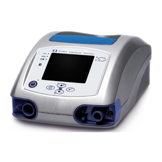
Аппарат искусственной вентиляции легких Puritan Bennett 560 предназначен для постоянной или периодической механической вентиляционной поддержки пациентов с весом тела не ниже 5 кг, которым требуется проведение механической вентиляции. Аппарат ИВЛ Puritan Bennett 560 представляет собой медицинский прибор ограниченного применения, который должен использоваться квалифицированным и обученным персоналом под руководством врача.
Данный вентилятор специально предназначен для взрослых и детей, которым необходимо проведение следующих видов инвазивной или неинвазивной вентиляции легких, как предписано наблюдающим врачом:
- Вентиляция с положительным давлением.
- Вспомогательная вентиляция с поддержкой/управлением, режимы SIMV или CPAP.
- Дыхание с управлением по давлению, объему или с поддержкой по давлению.
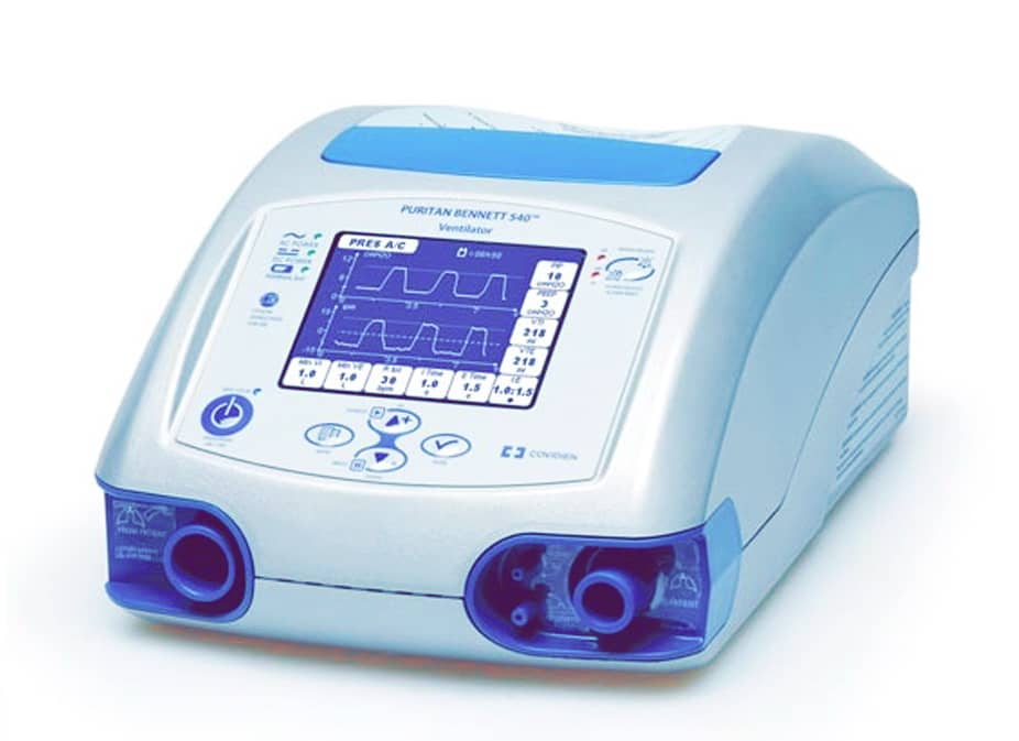
Вентилятор Puritan Bennett 560 рассчитан на использование в условиях медицинского учреждения, дома и в качестве переносного устройства. Не предполагается использовать его в качестве аппарата ИВЛ для машин скорой помощи.
Использование Puritan Bennett 560 COVIDIEN
Аппаратом искусственной вентиляции легких могут управлять:
- Врачи – специалисты в области заболеваний органов дыхания;
- Врачи;
- Медсестры;
- Персонал, ухаживающий за больными на дому (сиделки);
- Сам пациент и его родственники.
Переносной аппарат ИВЛ Puritan Bennett 560 использует микро-турбину для осуществления респираторной поддержки пациентов. Практикующее врачи могут пользоваться различными способами для подключения пациентов к этому аппарату: носовыми масками или лицевыми масками, эндотрахеальными или трахеотомическими
трубками. Пользователь может выбирать следующие режимы вентиляции:
- С поддержкой/управлением по объему (V A/C).
- С поддержкой/управлением по давлению (Р A/C).
- Синхронизированная перемежающаяся принудительная вентиляция (СППВ) с поддержкой по объему (V SIMV).
- Синхронизированная перемежающаяся принудительная вентиляция (СППВ) с поддержкой по давлению (Р SIMV).
- Самостоятельное дыхание с созданием постоянного положительного давления (СДППД) в дыхательных путях (СРАР).
- Вентиляция с поддержкой давлением и вентиляцией при отсутствии дыхания ВПД/ОД) (PSV/ST).
Система безопасности
В вентилятор встроена система сигнализации, которая постоянно отслеживает состояние пациента и машины на предмет сигналов о конкретных ошибках или неполадках, которые могут вызвать опасную ситуацию. Если такие ошибки или неполадки замечены, система сигнализации подает характерный сигнал тревоги, как зрительный, так и звуковой. Параметры срабатывания сигнализации по неполадкам прибора заданы на производстве, в то время как параметры срабатывания, связанные с пациентом, задаются пороговыми значениями величин, которые выбирают операторы (врачи в клинике или сиделки/медперсонал).
Настройки аппарата ИВЛ
Программная клавиша, так называемая клавиша блокировки, предотвращает доступ к настройкам параметров вентиляции, чтобы разграничить «врачебное» использование и «личное» использование самим пациентом.
Обогащение кислородом
Кислород может подаваться из внешнего источника низкого давления, но его расход должен быть не выше 15 л/мин, давление – 50 кПа, 7 PSI. Аппараты искусственной вентиляции легких (ИВЛ) Puritan Bennett 560 автоматически компенсирует избыточный расход, создаваемый при подаче кислорода извне.
Дыхательный контур
Вентилятор можно использовать с контуром пациента, снабженным одним или двумя патрубками (отводами). Если нужно контролировать объем выдыхаемого воздуха (как в случае с пациентами, которые самостоятельно дышать не могут), следует использовать контур с двумя патрубками для контроля дыхательного объема на выдохе.
Производитель Puritan Bennett 560
Производитель аппарата искусственной вентиляции легких Puritan Bennett 560 – Medtonic (COVIDIEN), страна производитель США.
Технические характеристики Puritan Bennett 560
Ниже указаны технические характеристики аппарата Puritan Bennett 560. Физическое описание (включая дополнительные приспособления).
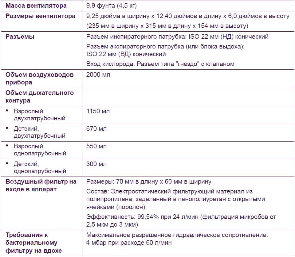
Полный перечень технических характеристик можно найти в инструкции. Скачать инструкцию на аппарат ИВЛ Puritan Bennett 560 COVIDIEN можно в конце статьи.
Видео обзор аппарата ИВЛ Puritan Bennett 560
Ниже представлено видео с обзором на аппарат ИВЛ Puritan Bennett 560 (Covidien, Medtronic).
Передняя панель Puritan Bennett 560
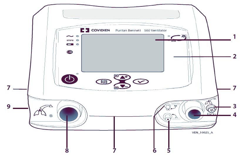
- ЖК- дисплей – отображает информацию о вентиляторе, в том числе время, проведенное пациентом на вентиляторе, версию ПО, режимы и настройки вентиляции, контролируемые и расчетные данные пациента и формы сигналов. Также при помощи дисплея пользователь может просматривать рабочие параметры и параметры системы сигнализации вентилятора и менять их, пользуясь панелью управления.
- Панель управления – предоставляет возможность управления настройками и работой вентилятора, а также светодиодную индикацию источника питания вентилятора, состояния «вкл/выкл» и приоритета сигналов тревоги. Функции управления включают в себя выключение и включение вентилятора, настройку режимов работы вентилятора, заглушение и отмену сигналов тревоги и установку параметров срабатывания системы сигнализации и рабочих параметров аппарата.
- Подключение датчика FiO2 – для датчика FiO2, который измеряет концентрацию кислорода в контуре пациента.
- Порт подключения пациента – предоставляет возможность поступления газа к пациенту через дыхательный контур.
- Разъем контроля давления пациента – Патрубок для контроля проксимального давления у пациента.
- Порт клапана выдоха – патрубок для подачи управляющего давления на клапан выдоха. Управляет открытием и закрытием клапана выдоха.
- Боковые и передние отверстия – вентиляционные отверстия, благодаря которым осуществляется охлаждение внутренних узлов вентилятора. Кроме того, они служат для распространения звукового сигнала тревоги.
- Порт «от пациента» – через него осуществляется измерение выдыхаемого объема, т.к. часть выдыхаемого газа через этот порт направляется на датчик расхода. Путем измерения этого расхода вычисляется величина VTE (Дыхательный объем на выдохе).
- Выход выдыхаемого газа – сюда подключается клапан выдоха.
Задняя панель
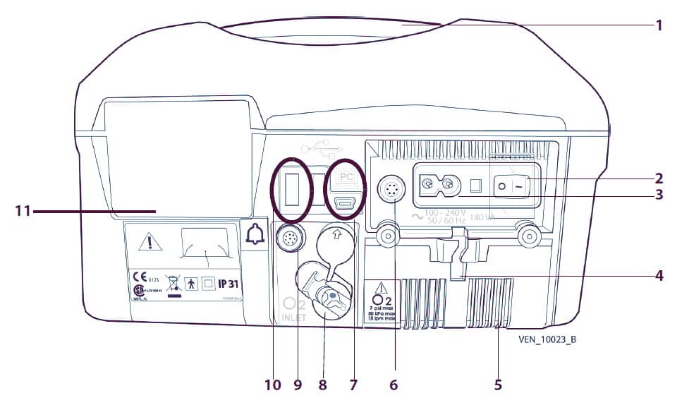
- Эргономичная ручка для переноски.
- Выключатель питания «Вкл/Выкл» (I/O) с защитной крышкой: В положении I прибор включен, в положении О — выключен.
- Разъем шнура электропитания переменного тока («Сетевой»).
- Система крепления шнура электропитания переменного тока («Сетевого»): Закрепляет шнур электропитания переменного тока во избежание случайного отсоединения.
- Крышка аккумуляторного отсека.
- Разъем для подключения шнура электропитания постоянного тока с направляющим ключом.
- Разъем для подключения ПК Мини- USB разъем для подключения тестирующего ПО вентилятора Puritan Bennett 560.
- Порт подвода O2: Соединяет вентилятор с источником кислорода низкого давления через переходник, надетый на патрубок ввода O2.
- Разъем вывода сигнала на устройство вызова медсестры: Используется для подключения вентилятора к системе вызова медсестры.
- Разъем устройства памяти USB: Разъем USB, который используется с программным обеспечением Puritan Bennett по поддержанию работы вентилятора. Имеются два порта USB типа А.
- Воздушный фильтр на входе в аппарат: Фильтрует воздух, поступающий в аппарат.
Панель управления
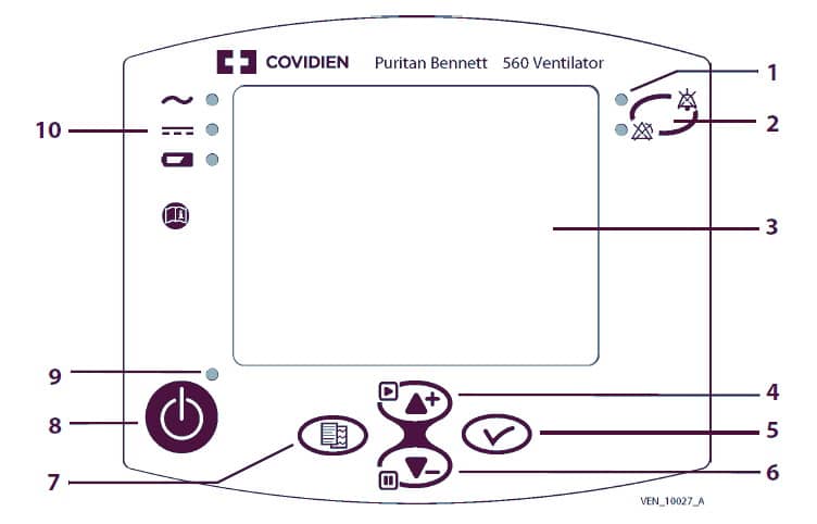
- Световые сигналы (два СДИ). Красные: (Непрерывный) Сработал сигнал тревоги ОВУ (очень высокого уровня); Сработал сигнал тревоги ВУ (высокого уровня). Желтый: Сработал сигнал тревоги СУ (среднего уровня).
- Клавиша УПРАВЛЕНИЕ СИГНАЛИЗАЦИЕЙ. Однократное нажатие заглушает звуковой сигнал тревоги на 60 секунд. Двойное нажатие останавливает звуковой и световой сигнал тревоги. Если ситуация, вызвавшая сигнал тревоги, исправлена, то сигнализация отменяется (за исключением сигнала по высокому давлению).
- Дисплей. Отображает режимы, настройки вентиляции, данные пациента и формы сигналов расхода или давления газа, конфигурацию вентилятора, а также позволяет управлять сигналами тревоги.
- Клавиша ВВЕРХ/ВОЗОБНОВИТЬ. Перемещает курсор вверх и увеличивает значение параметра. В ходе вентиляции возобновляет отслеживание форм сигналов расхода или давления в меню форм кривых.
- Клавиша ВВОД. Дает доступ к величинам настроек и проверке настроек в случае их изменения. Доступ в подменю.
- Клавиша ВНИЗ/ОСТАНОВИТЬ. Перемещает курсор вниз и уменьшает значение параметра. В ходе вентиляции останавливает отображение форм сигналов в меню форм кривых.
- Клавиша МЕНЮ. Изменяет отображаемое меню. Нажатием этой клавиши из меню вентиляции можно вызвать экран меню сигнализации. Когда к вентилятору подключается USB-карта памяти, нажатием этой клавиши можно вызвать экран меню устройства USB.
- Клавиша ВКЛ/ВЫКЛ ВЕНТИЛЯЦИЮ. Кратковременное нажатие на эту клавишу запускает вентиляцию. Для остановки вентиляции нажатие нужно удерживать в течение трех (3) секунд.
- Индикатор состояния вентиляции. Горит голубой индикатор: прибор включен и находится в состоянии готовности (вентиляция отключена). Голубой индикатор отключен: вентиляция включена.
- Индикаторы источников электропитания. Горит индикатор ПЕРЕМЕННЫЙ ТОК: подключен источник питания переменного тока. Горит индикатор ПОСТОЯННЫЙ ТОК: подключен источник питания постоянного тока. Индикатор ВСТРОЕННЫЙ АККУМУЛЯТОР горит постоянно: используется встроенный аккумулятор (никакой внешний источник не подключен). Индикатор ВСТРОЕННЫЙ АККУМУЛЯТОР мигает: аккумулятор заряжается.
Сигналы тревоги или неисправности
Сигналы тревоги или неисправности, создаваемые аппаратом Вентилятор Puritan Bennett 560, классифицируются по двум категориям:
- тревоги вентиляции (или те, что возникают в ходе работы);
- технические неисправности.
Некоторые из сигналов тревоги вентилятора могут регулироваться в зависимости от режима работы вентилятора. Также существуют нерегулируемые сигналы тревоги, предназначенные для создания сети безопасности и более безопасной вентиляции пациента.
Сигналы тревоги указывают на события, которые могут оказать влияние на ход вентиляции и требуют быстрого вмешательства.
Технические неисправности не влияют непосредственно на работу аппарата. Соответственно, пользователь не ставится в известность о технических неисправностях. Меню технического обслуживания доступно только для обученных техников с правом допуска.
Уровень приоритетности сигналов тревоги
Ниже перечислена иерархия сигналов тревоги в зависимости от того, насколько они критичны:
ОВУ, очень высокий уровень: Наступила критическая ситуация; вентиляция невозможна.
Постоянный звуковой сигнал / с постоянно горящим красным СДИ или без него / с выдачей сообщения или без него / с освещением дисплея или без него (возможны такие аварийные ситуации, при которых не будет как сообщения, так и освещения дисплея).
ВУ – высокий уровень: Критическая ситуация вскоре наступит; потенциальная угроза проведению вентиляции.
Высокочастотный прерывистый звуковой сигнал / мигающий красный СД-индикатор / сообщение / освещение дисплея.
СУ – средний уровень: До начала критической ситуации может пройти значительное время; в ближайшее время вентиляция не прервется.
Прерывистый звуковой сигнал, подаваемый со средней частотой / мигающий желтый СД-индикатор / сообщение / освещение дисплея.
Если не будут приняты какие-либо меры и если звуковой сигнал не будет прерван (заглушением звукового сигнала) или сброшен (путем сброса сигнализации) в течение 60 секунд, то сигнал ВУ будет подаваться на максимальной громкости.
Фильтры Puritan Bennett 560
Аппарат искусственной вентиляции легких Puritan Bennett 560 использует два типа фильтров:
- воздушный фильтр на входе в аппарат;
- бактериальный фильтр.
Воздушный фильтр на входе в аппарат
Этот фильтр, состоящий из поролона и специального наполнителя для удаления мелких частиц, расположенный в задней части вентилятора, фильтрует воздух по мере его поступления в прибор.
Бактериальный фильтр
Настоятельно рекомендуется устанавливать бактериальный фильтр как с однопатрубочными, так и с двухпатрубочными контурами. В двухпатрубочном контуре используются два бактериальных фильтра: один в порте К ПАЦИЕНТУ, другой — в порте ОТ ПАЦИЕНТА.
Увлажнитель Puritan Bennett 560
Увлажнитель добавляет влагу (водяной пар) и согревает газ в контуре пациента. Он вставляется в контур пациента между главным выходным патрубком и собственно пациентом.
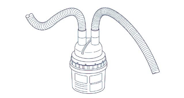
При использовании увлажнителя весь конденсат, образующийся в контуре пациента, собирается в водяной ловушке. При обнаружении любой влаги в контуре пациента влажные его части нужно заменить сухими.
Подключение датчика FIO2 (концентрации кислорода)
При назначении кислорода рекомендуется использовать датчик концентрации кислорода FiO2, который можно присоединить спереди к аппарату при помощи комплекта для определения FiO2 (концентрации кислорода).
Датчик кислорода требует калибровки, снимать и чистить его разрешается только квалифицированным сотрудникам. Если используется новый датчик, то его нужно выдержать при температуре окружающей среды в течение примерно 20 минут прежде чем устанавливать, калибровать и начинать вентиляцию.
Чтобы установить датчик FiO2 (концентрации кислорода):
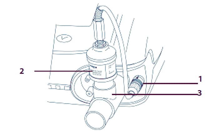
- Выньте устройство из герметичной упаковки.
- Установите переходник FiO2 (концентрации кислорода) в разъем FiO2 на вентиляторе (поз. 1).
- Соедините датчик FiO2 (концентрации кислорода) (поз.2) с переходником диаметром 15 мм (поз.3).
- Установите переходник на выходной порт К ПАЦИЕНТУ, как показано. Закрепите контур пациента за переходником.
Калибровка датчика кислорода FiO2
В видео представлена последовательность действий при калибровке датчика кислорода (FiO2) аппарата ИВЛ Puritan Bennett 560 и для чего это нужно.
Аккумулятор Puritan Bennett 560
Вентилятор Puritan Bennett 560 удовлетворяет всем условиям электробезопасности, внутренний аккумулятор литий-ионная батарея. Максимальный рекомендуемый срок хранения встроенного аккумулятора два года. Не следует брать в работу аккумулятор, который пролежал на складе два года и ни разу не использовался.
Для продления срока службы аккумулятора важно, чтобы его периодически перезаряжали. Не следует хранить аккумуляторы длительное время без перезарядки, это сокращает срок их службы.
Емкость аккумулятора Puritan Bennett 560
Резервная емкость встроенного аккумулятора зависит от уровня заданных параметров вентиляции, от условий окружающей среды (в основном, от температуры) и от физиологических характеристик пациента.
Проверка уровня заряда аккумулятора подразумевает, что на момент проверки вентилятор находится в работе и работает от аккумулятора. Чтобы проверить уровень заряда аккумулятора, следует временно отключить вентилятор от источника переменного тока (либо в режиме готовности, либо в ходе вентиляции) и прочесть значение уровня заряда в процентах, которое показывается рядом с символом аккумулятора, отображаемым в верхней части экрана дисплея.
Работа аккумулятора Puritan Bennett 560
Перед тем, как пользоваться встроенным аккумулятором вентилятора, следует убедиться, что он полностью заряжен и удерживает заряд. Запасные вентиляторы или вентиляторы, находящиеся на хранении, должны быть подключены к источнику переменного тока, чтобы защитить целостность аккумулятора.
Когда прибор впервые запускается после полной перезарядки встроенного аккумулятора, возможно срабатывание сигнального устройства и сигнализации по состоянию аккумулятора. В этом случае нужно подключить прибор к сети переменного тока и перезапустить питание прибора.
В случае прекращения подачи переменного тока или отсоединения от внешнего источника переменного или постоянного тока вентилятор автоматически переключается на встроенный аккумулятор и происходит следующее:
- Символ аккумулятора отображается в верхней части строки общих сведений.
- Остаток емкости аккумулятора отображается справа от соответствующего символа.
- Индикатор «ВСТРОЕННЫЙ АККУМУЛЯТОР» в левой верхней части передней панели индикатора горит постоянно.
- Срабатывает сигнализация по прекращению подачи электропитания от внешнего источника.
Если вентиляция останавливается, остаток емкости аккумулятора отображается в виде процента заряда аккумулятора.
Если вентилятор работает, то остаток емкости встроенного аккумулятора кратковременно показывается в виде процента. Затем, после того, как вентилятор рассчитает срок работы от аккумулятора (что может занять до двух минут, в зависимости от энергопотребления вентилятора) остаток заряда аккумулятора отображается в часах и минутах (с округлением до пятнадцати минут).
С момента срабатывания сигнала «БАТАРЕЯ РАЗРЯЖЕНА», если не подключить прибор к внешнему источнику тока, могут сработать другие сигналы тревоги в связи с недостаточным уровнем напряжения. В последней стадии разрядки сигнал «БАТАРЕЯ РАЗРЯЖЕНА» становится постоянным, и вентиляция в любой момент может быть прекращена.
Проверка аккумулятора Puritan Bennett 560
Вентилятор постоянно автоматически проверяет состояние встроенного аккумулятора, даже когда он не используется в качестве основного источника энергии. Сигнал «СБОЙ БАТАРЕИ 1» срабатывает в случае обнаружения любой проблемы с аккумулятором или зарядным устройством.
Раз в месяц нужно отсоединять вентилятор от внешнего источника энергии, чтобы проверить целостность соединений между встроенным аккумулятором и другими узлами вентилятора.
Перезарядка аккумулятора Puritan Bennett 560
Когда уровень заряда в аккумуляторе недостаточен, если судить по показателям остаточной емкости, необходимо выполнить перезарядку аккумулятора. В общем рекомендуется ставить вентилятор на зарядку, когда уровень заряда в аккумуляторе падает ниже 80%, а также систематически перезаряжать вентилятор после хранения и перед повторным использованием.
Во избежание перехода с одного источника питания на другой и для продления срока службы аккумулятора, он при присоединении к источнику переменного тока не будет заряжаться до тех пор, пока заряд не упадет ниже 85 — 90%.
Чтобы перезарядить встроенный аккумулятор, нужно подсоединить вентилятор к источнику переменного тока. Когда аккумулятор полностью заряжается, индикатор ВСТРОЕННЫЙ АККУМУЛЯТОР гаснет.
Нет необходимости запускать вентилятор в работу при зарядке аккумулятора, пополнение заряда при работающем вентиляторе приводит к увеличению времени, необходимого для полной зарядки встроенного аккумулятора.
При перезарядке истощенного аккумулятора может понадобиться оставить вентилятор на зарядке на протяжении 6 (шести) часов в режиме готовности или около 13 часов при работающем вентиляторе.
Хранение аккумулятора
Если вентилятор необходимо сдать на хранение на длительный срок, не обязательно вынимать из него аккумулятор. Однако хранить вентилятор следует в сухом прохладном месте, хорошо вентилируемом, при следующих условиях:
- Температура: около 21 °C (70 °F);
- Влажность: менее 80% относительной влажности.
Если аккумулятор хранится более месяца при температуре выше 21 °C (70 °F) или более двух недель — при температуре свыше 45 °C (113 °F), то это может сказаться на остаточной емкости аккумулятора. Перед повторным использованием такой аккумулятор следует перезарядить.
Если вентилятор в течение более чем 30 дней хранился подключенным к источнику переменного тока, перед началом вентиляции включите его выключателем I/O (вкл/выкл) в задней части аппарата и дайте ему зарядиться в течение 15 минут.
Очистка Puritan Bennett 560
Протирайте все внешние панели и поверхности перед и после работы с каждым из пациентов, а также по мере надобности, чтобы вентилятор всегда был чистым. Загрязненные или испачканные участки вентилятора нужно очищать перед выполнением технического обслуживания, а также перед отправкой на хранение.
Чтобы почистить поверхность вентилятора, нужно:
- Намочить чистую мягкую ткань в некрепком мыльно-водном растворе или в другом разрешенном моющем растворе.
- Тщательно отжать ткань, чтобы удалить избыток жидкости.
- Слегка протереть наружный корпус вентилятора, следя за тем, чтобы жидкость не попала в какие-либо из отверстий на его поверхности. См. предупреждение выше.
- Вытереть насухо поверхность вентилятора чистой мягкой безворсовой тканью.
Растворы, которыми разрешено пользоваться для чистки внешних
поверхностей вентилятора:
- Слабый раствор средства для мытья посуды;
- 70% изопропиловый спирт (для протирки);
- 10% хлорный отбеливатель (90% — вода из крана);
- Глутаральдегид;
- Больничные дезинфектанты в форме раствора;
- Перекись водорода;
- 15% р-р аммиака (85% — вода из-под крана);
- Домашние чистящие средства, содержащие аммиак;
- Домашние чистящие средства.
Техническое обслуживание Puritan Bennett 560
Необходимо регулярно проверять чистоту воздушного фильтра на входе в аппарат,который расположен в задней части вентилятора. При необходимости фильтр заменяют до истечения рекомендованного периода замены. Если вовремя не заменить воздушный фильтр на входе в аппарат или допустить работу вентилятора «без» — Yulia фильтра, это может привести к серьезной поломке аппарата. Воздушные фильтры являются одноразовыми изделиями. Запрещается мыть, чистить или повторно использовать их.
При использовании вентилятора в помещении проверку состояния воздушного фильтра следует проводить раз в месяц. При использовании аппарата на открытом воздухе или в запыленном помещении проверку воздушного фильтра следует выполнять еженедельно и заменять фильтр по необходимости.
Рекомендуемый график технического обслуживания
При использовании в нормальных условиях — относительно незапыленной атмосфере и без повреждений аппарата и его узлов (толчки, трещины, сильная загрязненность) — сроки замены расходных материалов вентилятора приведены ниже.
Расходные материалы и сроки их замены
Воздушный фильтр на входе в аппарат (Поролон + мелкие частицы).
Раз в месяц или чаще, в зависимости от степени загрязнения.
Инспираторный бактериальный фильтр.
Смотреть рекомендации производителя.
Контур пациента.
Смотреть рекомендации производителя. Одноразовый однопользовательский (для одного пациента).
Датчик FiO2.
От 14 до 18 месяцев или чаще в случае постоянных сбоев в калибровке.
Блок выдоха.
Раз в 4 месяца и для каждого нового пациента.
Замена встроенного аккумулятора
Встроенный аккумулятор нужно заменять, когда его емкость падает ниже 3450 мАh. Следует иметь в виду, что по соображениям экологического характера вентилятор и его узлы — включая встроенный аккумулятор — нельзя утилизировать как бытовые отходы. Вентилятор и его узлы следует отправлять на раздельный сбор вторсырья для возможной утилизации и повторного использования с соблюдением всех применимых законодательных норм.
Режимы вентиляции Puritan Bennett 560
Ниже представлено общее описание различных режимов вентиляции и типов дыхания, которые может обеспечивать Вентилятор Puritan Bennett 560. По умолчанию в приборе установлен режим P A/C.
Режимы с поддержкой/управлением (A/C)
При задании режимов с поддержкой/управлением такие параметры аппаратно инициируемых вдохов, как объем, давление, время вдоха и частота дыхания задаются лечащим врачом. Если у пациента между аппаратными вдохами случается самопроизвольный вдох, то вентилятор подает ему воздух в объеме или под давлением, заданными соответствующими установками, а также в течение заданного времени.
Вне зависимости от того, спонтанные это дыхания или аппаратные, каждое дыхание совершается в том же самом заданном объеме (или при том же заданном давлении) и за одно и то же заданное время вдоха.
Режимы с поддержкой/управлением бывают:
- V A/C (с поддержкой/управлением по объему), если заданным параметром дыхания является объем;
- P A/C (с поддержкой/управлением по давлению), если заданным параметром дыхания является давление.
Режимы SIMV
При задании режима SIMV (Синхронизированная перемежающаяся принудительная вентиляция, СППВ) такие параметры аппаратно инициируемых вдохов, как объем, давление, время вдоха и частота дыхания задаются лечащим врачом. Эти принудительные вдохи синхронизированы с дыхательными усилиями пациента. Если между аппаратными вдохами пациент делает вдох самостоятельно, вентилятор осуществляет самостоятельное дыхание с поддержкой давлением.
Самостоятельное дыхание с постоянным положительным давлением в дыхательных путях (CPAP) недоступно в режимах СППВ.
Режимы SIMV бывают:
- V SIMV (СППВ с поддержкой по объему), если заданным параметром принудительного дыхания является объем;
- P SIMV (СППВ с поддержкой по давлению), если заданным параметром принудительного дыхания является давление.
Режим CPAP
В режиме CPAP вентилятор поддерживает постоянный уровень давления в дыхательных путях пациента.
Режим PSV
В режиме PSV постоянный уровень давления поддерживается в дыхательных путях пациента во время выдоха. Кроме того, каждое из дыханий пациента вентилятор поддерживает заданным врачом давлением поддержки — Pressure Support. Это дает те же преимущества, что и метод CPAP, дополнительно помогая пациенту в поступлении газа в легкие.
Запчасти и расходные материалы
Ниже указан перечень приспособлений для Вентилятор Puritan Bennett 560. Чтобы заказать запчасти или приспособления, свяжитесь с поставщиком оборудования или с представителем компании Covidien.
Вентилятор поставляется в следующей комплектации: отпечатанное Руководство для пользователя, компакт-диск с Руководством для практикующего врача (печатный экземпляр можно заказать отдельно); Один контур пациента с клапаном; один комплект из 6 (шести) комбинированных воздушных фильтров для входного патрубка (поролоновый фильтр/фильтр мелких частиц); одна сумка для переноски; один кислородный переходник; и один шнур электропитания переменного тока.
Перечень расходных материалов
- Сумка для переноски (серая).
- Впускной патрубок для кислорода.
- Тележка для вентилятора.
- Двойная сумка (синяя или розовая).
- Шнур электропитания переменного тока (сетевой).
- Шнур электропитания постоянного тока (для подключения к внешнему источнику постоянного тока, например, к автомобильному разъему постоянного тока напряжением 12 В).
- Кабель вызова медсестры (5 метров).
- Блок выдоха, одно пользовательский (голубой).
- Комбинированный воздушный фильтр, мелкопористый (6 штук в комплекте).
- Встроенный аккумулятор.
- Внешний аккумулятор.
- Комплект для измерения концентрации кислорода.
- Датчик FIO2 (концентрации кислорода).
Скачать инструкцию на Puritan Bennett 560
Скачать инструкцию по применению и другую документацию на аппарат искусственной вентиляции легких Medtonic (COVIDIEN) Puritan Bennett 560 можно здесь.
Руководство пользователя ( user manual ) на русском языке Puritan Bennett 560 скачать.
Декларация соответсвия Puritan Bennett 560 скачать.
Регистрационное удостоверение Puritan Bennett 560 скачать.
Респираторное обеспечение — каталог скачать.
Трахеостомические трубки и принадлежности — каталог скачать.
Кислородная и аэрозольная терапия — каталог скачать.
Также смотрите Puritan Bennett 840 аппарат ИВЛ.
-
Contents
-
Table of Contents
-
Troubleshooting
-
Bookmarks
Quick Links
Clinician’s Manual
Puritan Bennett
TM
560 Ventilator
Related Manuals for Covidien Puritan Bennett 560
Summary of Contents for Covidien Puritan Bennett 560
-
Page 1
Clinician’s Manual Puritan Bennett 560 Ventilator… -
Page 2
Nothing in this manual shall limit or restrict in any way Covidien’s right to revise or otherwise change or modify the equipment (including its software) described herein, without notice. In the absence of… -
Page 3: Table Of Contents
Table of Contents Preface Purpose of this Manual …………xv Qualification of Personnel .
-
Page 4
P A/C Mode Parameters and Setting Ranges ……. . . 3-11 V A/C Mode Parameters and Setting Ranges . -
Page 5
Table of Contents 6.11 Connecting the Nurse Call Cable ……….6-26 Operating Procedures Turning on the Ventilator . -
Page 6
Battery Operation …………8-2 Testing the Battery . -
Page 7
Table of Contents Modes and Breath Types Modes of Ventilation …………D-1 D.1.1 Assist/Control (A/C) Modes . -
Page 8
Page Left Intentionally Blank viii… -
Page 9
List of Figures Figure 1-1. Locations of Labels—Top-Front View ……….. . 1-25 Figure 1-2. … -
Page 10
Figure 5-5. Pausing the Audible Portion of Alarms ……….. . 5-6 Figure 5-6. … -
Page 11
Puritan Bennett 560 Ventilator …….. -
Page 12
Page Left Intentionally Blank… -
Page 13
List of Tables Table 1-1. Ventilator Symbols …………..1-19 Table 1-2. … -
Page 14
Table B-19. Performance Specifications …………. . B-10 Table B-20. … -
Page 15: Purpose Of This Manual
Information regarding your product warranty is available from your sales representative or Covi- dien. Extended Service The Puritan Bennett 560 Ventilator offers extended service contracts/warranties for purchase when the ventilator is purchased. Please contact your local Covidien sales or service represen- tative for additional information.
-
Page 16: Technical Support
Here, you will find answers to frequently asked questions about the product and other Covidien products 24 hours a day, 7 days a week. If you require further assistance, contact your local Covidien represen- tative.
-
Page 17
Fax: +358 9 725 192 89 Tel: +33 1 57 32 35 10 Fax: +33 1 57 32 70 10 Covidien Hellas SA Covidien Hungary Covidien Ireland Commercial Ltd 8 Fragoklisias Street 1095 Budapest Block G, Ground Floor, Maroussi, 151 25 Mariassy u. -
Page 18
Fax: + 46 8 502 521 10 Tel: +34 91 275 48 54 (option 3) Fax: +34 91 276 89 33 Covidien Switzerland Covidien UK & Ireland Covidien Singapore Roosstr. 53 Unit 2, Talisman Business Park Singapore Regional Service Centre… -
Page 19: Safety Information
1 Safety Information Definitions This manual uses three indicators to highlight critical information: warning, caution, and note. They are defined as follows: WARNING Indicates a condition that can endanger the patient or the ventilator operator. Caution Indicates a condition that can damage the equipment. Note Indicates points of particular emphasis, that make operation of the ventilator more efficient or convenient.
-
Page 20
Safety Information WARNING: Be aware this manual describes how to respond to ventilator, but it does NOT tell you how to respond to the patient. WARNING: While the ventilator is in use, an alternative means of ventilation should always be available in the event of a ventilator problem. -
Page 21: Warnings Regarding Installation And Environment Of Use
WARNING: If the ventilator fails the alarm tests or if you cannot complete the tests, refer to Chapter 5.8, “Troubleshooting” or call your equipment supplier or Covidien. WARNING: When an alarm condition is triggered, or there is evidence of a patient-ventilator fault or problem, examine the patient first before examining the ventilator.
-
Page 22
Safety Information Dangerous Goods (DG) Class 9 – Miscellaneous, when transported in commerce. As such, the Puritan Bennett 560 Ventilator and/or the associated Lithium-ion battery are subject to strict transport conditions under the Dangerous Goods Regulation for air transport (IATA: International… -
Page 23
41°C (106°F). This may lead to undesirable side effects for the patient. To avoid injury to the patient move the patient and the ventilator to a cooler location. For more information, contact Covidien. … -
Page 24: Warnings Regarding Electrical Power Supplies
Safety Information WARNING: Handle the ventilator with care during and after use, particularly when ambient temperatures are high. Some ventilator surfaces may become hot, even if safety specifications are not exceeded. Warnings Regarding Electrical Power Supplies 1.2.3 WARNING: Never connect your ventilator to an electrical outlet controlled by a wall switch because the power may be inadvertently turned off.
-
Page 25: Warnings Regarding Hoses And Accessories
Warnings WARNING: Due to its limited internal battery’s reserve capacity, the ventilator should only be operated on the internal battery when no other power source is available. Ensure that the internal battery never becomes fully discharged. WARNING: When using a car auxiliary adapter (cigarette lighter) ensure the car has been started prior to plugging in the ventilator’s DC adapter.
-
Page 26
Safety Information WARNING: Before opening the packaging for the Patient Circuit, ensure that no damage is evident to the packaging or its contents. Do not use if evidence of damage exists. WARNING: The patient circuit should not be changed during ventilation. … -
Page 27
Warnings WARNING: If the ventilator is used indoors, the condition of the air inlet filter should be checked monthly. If the ventilator is used outdoors or in a dusty environment, the filter should be checked weekly and replaced as necessary. … -
Page 28
– especially when filters are replaced. WARNING: To ensure proper performance of the ventilator, use a patient circuit recommended by Covidien in this manual; refer to Chapter 6, “Installation and Assembly” and Appendix H, “Parts and… -
Page 29: Warnings Regarding Settings
Warnings WARNING: Do not use Nurse Call devices that operate based on the closure of an electrical circuit, because the devices often do not take into account possible cable disconnection or a total loss of power. Ensure that the Nurse Call device is always connected to the ventilator. Warnings Regarding Settings 1.2.5 …
-
Page 30
Safety Information WARNING: In adult or pediatric use ensure that the adjusted tidal volume is compatible with the needs of the patient. WARNING: When changing the mode during ventilation, significant transitions of pressure, flow or cycling rate might occur, depending on the difference between the modes. Before setting the new mode, first ensure that the settings between the different modes are compatible. -
Page 31: Warnings Regarding Usb Memory Device
WARNING: To ensure proper servicing and avoid the possibility of physical injury to personnel or damage to the ventilator, only personnel authorized and qualified by Covidien should attempt to service or make authorized modifications to the Puritan Bennett™ 560 Ventilator.
-
Page 32
Do not attempt to open, repair or otherwise service the ventilator yourself. Doing so might endanger the patient, damage the ventilator, and/or void your warranty. Only personnel authorized and qualified by Covidien should repair, open or service the ventilator. … -
Page 33
Warnings WARNING: The exhalation block is intended for single use by a single patient . It may periodically be cleaned, but it cannot be disinfected or sterilized. To maintain good measurement quality when used continuously, clean the exhalation block periodically (refer to section 9.3, “Cleaning the Exhalation Block”). -
Page 34: Warnings Regarding Oxygen
Safety Information during the start-up procedure), the oxygen and power supplies should be disconnected and use of the device stopped immediately. WARNING: Before using the ventilator’s internal battery, ensure that the battery is fully charged and that the charge holds. Back up ventilators or those in storage should be connected to an AC power source to protect the integrity of the battery.
-
Page 35
WARNING: The Puritan Bennett 560 Ventilator is designed to deliver a percentage of oxygen equal or lower than 50%. Do not exceed this value as this may cause the ventilator to malfunction and put the patient at risk. -
Page 36: Warnings Regarding Electromagnetic Interference
To prevent any interference with the internal sensors of the ventilator, do not install a humidifier upstream of the ventilator. WARNING: To ensure stability, when the Puritan Bennett 560 Ventilator is mounted on a cart, the weight of the oxygen bottle should not exceed 14 kg (30 lbs). WARNING: The oxygen supply hose ages even when it is not in use and should be replaced periodically.
-
Page 37: Symbols And Markings
Table 1-1. Ventilator Symbols Symbols Descriptions It is essential to read, understand, and follow these instructions before using the Puritan Bennett 560 Ventila- tor (ISO 7000-0434A). This symbol appears on the ventilator’s back panel, see Table 1-2. , item 5. Type BF applied part (IEC 60417-5333).
-
Page 38
Safety Information Table 1-1. Ventilator Symbols (Continued) Symbols Descriptions This symbol appears on the ventilator’s front panel DOWN/FREEZE key; see Figure 2-3. on page 2-6, item 6. This key is used to: move the LCD display’s cursor downwards, line-by-line; decrease the value of displayed and selected parameter settings;… -
Page 39
Symbols and Markings Table 1-1. Ventilator Symbols (Continued) Symbols Descriptions Software lock enabled. This symbol appears on the upper-left of the ventilator’s LCD display when the keyboard Locking key is enabled; see section 7.8, “Locking the Control Panel.” Internal battery. This symbol appears on the top-center of ventilator’s LCD display to indicate that the ventilator is being powered by its internal battery. -
Page 40
This symbol indicates a communications port for interfacing with a USB connector. See Figure 2-2. , item 11. PC connector. This symbol indicates a port that can be used by authorized Covidien product service personnel or Covidien service personnel for software maintenance. See Figure 2-2. , item 10. -
Page 41: Labels / Identification And Instruction Information
Labels / Identification and Instruction Information Table 1-1. Ventilator Symbols (Continued) Symbols Descriptions Fragile. Keep dry. Keep away from direct sunlight. This side up. Labels / Identification and Instruction Information Various labels or specific markings are affixed to the ventilator that describe precautions to be taken for the correct use of the ventilator and contribute to the traceability of the product.
-
Page 42
Safety Information Table 1-2. Ventilator Labels and Markings (Continued) 7. Identification label (Figure 1-4. ) 1 Location of AC power cable connector 1 Location of DC power cable connector 8. AC power (mains) cable connector marking 9. External cable connector marking (Figure 1-3. ) (Figure 1-3. ) 10. PC connection marking (Figure 1-3. ) 11. -
Page 43: Figure 1-1. Locations Of Labels-Top-Front View
Labels / Identification and Instruction Information Figure 1-1. Locations of Labels—Top-Front View Figure 1-2. Locations of Labels—Front-Left View Clinician’s Manual 1-25…
-
Page 44: Figure 1-3. Location Of Labels And Markings-Rear View
Safety Information Figure 1-3. Location of Labels and Markings—Rear View Figure 1-4. Location of Labels—Bottom View 1-26 Clinician’s Manual…
-
Page 45: Ventilator Overview
The ventilator is suitable for use in institutional, home, and portable settings. It is not intended for use as an emergency transport ventilator. The Puritan Bennett 560 Ventilator is suitable for use on commercial aircraft, per FAA require- ments. See section B.11, “Standards Compliance and IEC…
-
Page 46: Contraindications
Nurses • Homecare providers • Patient and patient’s families • For more details on the knowledge and skill requirements for operating the Puritan Bennett 560 Ventilator, see Appendix A, “Patient/Caregiver Checklist.” WARNING: This ventilator must be used only under the responsibility and on the prescription of a doctor.
-
Page 47: Device Classification
Device Classification Pressure Support Ventilation with apnea ventilation (PSV/ST) • Safety Net Incorporated in the ventilator design is an alarm system that continuously monitors both patient and machine for signs of specific errors or faults that could lead to an unsafe condition. Should any of these errors or faults be detected, the alarm system announces the specific alarm condition both audibly and visually.
-
Page 48: Front Panel
Ventilator Overview Front Panel Figure 2-1. Front Panel LCD display—Shows information about the ventilator, Exhalation valve port—Nipple for providing piloting pres- including patient hours and software version, ventilation sure to the exhalation valve. Controls the open-closed posi- modes and settings, and monitored and calculated patient tion of the exhalation valve.
-
Page 49: Back Panel
Back Panel Back Panel Figure 2-2. Back Panel Ergonomic carrying handle. PC cable connector: USB mini-B connector used for Puritan Bennett Ventilator test software. On/Off (I/O) switch with protective cover: inlet port: Device powered on in position I; device Connects the ventilator to a low pressure oxygen switched off in position 0.
-
Page 50: Control Panel
Ventilator Overview Control Panel Figure 2-3. Control Panel Alarm indicators (two LEDs): DOWN/FREEZE key: Red indicator: • Moves the cursor down and decreases parameter values. • Continuous: very high priority (VHP) alarm activated • During ventilation, freezes displayed waveform in the Wave- form menu.
-
Page 51: Ventilation Menu
Ventilation Menu Ventilation Menu Figure 2-4. Ventilation Menu Display Ventilation menu with ventilation on standby. Ventilation menu during ventilation. General information line: Ventilation settings: Preferences menu access line: Shows the current ventilation mode, Shows the specific ventilation parame- Highlight this line and press the ENTER along with the following: ter values for the currently selected key to show the Preferences…
-
Page 52: Alarm Menu
Ventilator Overview Alarm Menu Figure 2-5. Alarm Menu Alarm menu with ventilation on standby. Alarm menu when not in standby. Title line: Alarm settings: Access line to Alarm Logs menu. Shows ventilation mode and the fol- Shows the specific alarm parameter Highlight this line and press the ENTER lowing symbols: values for the currently selected venti- key to show the Alarm Logs…
-
Page 53: Waveforms Menu
Waveforms Menu Waveforms Menu 2.10 The display of waveforms (Figure 2-6. ) is optional and can be selected using the Menu (see Chapter 4, “Monitored Parameters”). The Waveform menu is only accessible when ventilation is active. Figure 2-6. Waveforms Menu Title line: Graphic zone: Numeric zone: •…
-
Page 54: Usb Memory Device Menu
Keep in mind that troubleshooting information is available in this manual to assist you in the event of a problem. See Chapter 5, “Alarms and Troubleshooting.” If you cannot determine the cause of a problem, contact your equipment supplier or Covidien. See section 10.5, “Service Assistance.”…
-
Page 55: Operating Parameters
3 Operating Parameters This chapter describes ventilation and alarm parameters and their setting ranges for each ven- tilation mode. For a listing of operating parameters and monitored patient data, see Table B- 11. on page B-8. For further information about the different ventilation modes and breath types provided by the Puritan Bennett™…
-
Page 56: Figure 3-2. Menus In Psv Mode With Leakage Configuration
Operating Parameters Figure 3-2. Menus in PSV Mode with Leakage Configuration The ventilation parameters and setting ranges available in PSV mode are listed in Table 3-1. Table 3-1. Ventilation Parameters in PSV Menu Name Units Min. value Max. value Adjustment Default Linked resolution value parameters P Support Standby: 2 Standby: 55…
-
Page 57: Table 3-2. Alarm Parameters In Psv Mode
PSV Mode Parameters and Setting Ranges Table 3-2. lists the available alarm settings in PSV mode. Table 3-2. Alarm Parameters in PSV Mode Name Units Min. Max. Adjustment Default Linked value value resolution value parameters Min VTI 2000 Max VTI Max VTI 3000 2,000 Min VTI Min VTE (with exhalation…
-
Page 58
Operating Parameters The different levels available are as follows: Rise time = 200 ms Rise time = 400 ms Rise time = 600 ms Rise time = 800 ms These time ranges are determined by the pressure setting required, the breath rate and the phys- iological condition of the patient. -
Page 59: Figure 3-3. Exhalation Trigger Sensitivity
PSV Mode Parameters and Setting Ranges Figure 3-3. Exhalation Trigger Sensitivity Seconds Exhalation Inspiration Note: See section 7.2.2, “Changing the Setup Menu Parameters” for positive and negative E Sens settings. Backup R Backup R allows you to determine the frequency of ventilation breaths to be applied in the event of prolonged apnea –…
-
Page 60
Operating Parameters Note: During apnea ventilation, the ventilator delivers machine controlled breaths according to a backup rate (Backup R)—as long as no inspiratory trigger has been detected. Note: The Backup R value applied depends on the Rate setting. … -
Page 61
PSV Mode Parameters and Setting Ranges Max I Time defines the maximum duration of time during which the inspiratory phase is main- tained. The switch-over to exhalation occurs at the latest after this time has expired. By default, if no parameter is set, the maximum time (Max I Time = AUTO) is the shortest time between a fixed time of 3 seconds and half the duration of the patient’s inspiratory breaths expressed in seconds. -
Page 62: Cpap Mode Parameters And Setting Ranges
Operating Parameters Max Rtot (Max Alarm Setting)—TOTAL BREATH RATE The maximum rate threshold set is used to warn of hyperventilation or ventilator autotriggering. The alarm setting is used to trigger the HIGH RATE alarm. See Chapter 5, “Alarms and Troubleshoot- ing.”…
-
Page 63: Table 3-3. Ventilation Parameters In Cpap Menu
CPAP Mode Parameters and Setting Ranges Table 3-3. Ventilation Parameters in CPAP Menu Name Units Min. Max. Adjustment Default Linked value value resolution value parameters PEEP mbar or Auto Backup R Apnea Time Not available if Apnea alarm is set to OFF in Preferences menu. Table 3-4. …
-
Page 64
Operating Parameters VTI (Min and/or Max Alarm Settings)—INSPIRATORY TIDAL VOLUME It is possible to set a Min, Max, or both Tidal Volume alarm threshold for the patient’s inspired tidal volume during a cycle. This setting is used to trigger an alarm if the tidal volume inspired by the patient is lower than the minimum threshold set (LOW VTI alarm) or greater than the maximum threshold set (HIGH VTI alarm). -
Page 65: P A/C Mode Parameters And Setting Ranges
P A/C Mode Parameters and Setting Ranges Min FiO and Max FiO thresholds are related and their settings must maintain a minimum differ- ence of 10% between the two. Min and Max FiO settings can be set to OFF if an FiO sensor is not connected.
-
Page 66: Table 3-5. Ventilation Parameters In Pa/C Mode Menu
Operating Parameters Table 3-5. Ventilation Parameters in PA/C Mode Menu Name Units Min. value Max. value Adjustment Default Linked resolution parameters value Standby: 2 Standby: 55 PEEP mbar, or Valve configuration: 5 Valve configuration: 55 Leak configuration: 6 Leak configuration: 30 PEEP Standby: OFF mbar, or Valve configuration: OFF…
-
Page 67
P A/C Mode Parameters and Setting Ranges Pi—Inspiratory Pressure When Relative pressure is set to YES in the Setup menu, Pi allows you to determine inspiratory pressure added to PEEP during the inspiratory phase. In this configuration, the sum of Pi and PEEP must not exceed 55 mbar. When Relative pressure is set to OFF in the Setup menu, Pi allows you to determine inspiratory absolute pressure. -
Page 68
Operating Parameters Rise Time is established only if Insp Time ≥0.9 seconds • Rise Time is established only if Insp Time ≥1.1 seconds. • Rate—RESPIRATORY RATE Rate allows you to define the minimal frequency of mandatory ventilator breaths. If the patient actuates the inspiration trigger, total Rate may increase. Insp Time—INSPIRATORY TIME This parameter allows the user to set the inspiratory time to 0.3-6.0 s. -
Page 69
P A/C Mode Parameters and Setting Ranges VTI (Min and/or Max Alarm Settings)—INSPIRATORY TIDAL VOLUME It is possible to set a Min, Max, or both Tidal Volume alarm threshold for the patient’s inspired tidal volume during a cycle. This setting is used to trigger an alarm if the tidal volume inspired by the patient is lower than the minimum threshold set (LOW VTI alarm) or greater than the maximum threshold set (HIGH VTI alarm). -
Page 70: A/C Mode Parameters And Setting Ranges
Operating Parameters Min and Max FiO thresholds are related and their settings must maintain a minimum difference of 10% between the two. Min and Max FiO settings can be set to OFF if an FiO sensor is not connected. Settings are auto- matically restored once a sensor is reconnected.
-
Page 71
V A/C Mode Parameters and Setting Ranges Table 3-7. Ventilation Parameters in V A/C Ventilation Mode (Continued) Name Units Min. Max. Adjustment Default Linked value resolution parameters value value Insp Time Rate Apnea Time I Sens – – – Sigh Rate Sigh Vt –… -
Page 72
Operating Parameters Ramp Pattern—FLOW SHAPE This parameter is used to adjust the flow distribution shape (or ramp pattern) during the inspira- tory phase. The three flow patterns available are: Ramp Pattern: (square waveform) or constant flow • Ramp Pattern: Decelerated (sawtooth waveform) or decreasing flow. •… -
Page 73
V A/C Mode Parameters and Setting Ranges The Min PIP (or Low Pressure) setting determines the trigger threshold for the PATIENT DISCON- NECTION alarm. See Chapter 5, “Alarms and Troubleshooting.” If this pressure level is not reached during a fixed time, the alarm is triggered. … -
Page 74: P Simv Mode Parameters And Setting Ranges
Operating Parameters (Min and/or Max Alarm Settings)—FRACTION OF INSPIRED OXYGEN An FiO sensor connected to the patient circuit allows you to determine that the correct level of oxygen is being delivered to the patient. Min and Max FiO thresholds can be set to trigger LOW FiO or HIGH FiO alarms.
-
Page 75: Table 3-10. Alarm Parameters In P Simv Ventilation Mode
P SIMV Mode Parameters and Setting Ranges Table 3-9. Ventilation Parameters in P SIMV Ventilation Mode (Continued) Name Units Min. Max. Adjustment Default Linked resolution parameters value value value Rate Max Rtot Insp Time Insp Time Rate Apnea Time E Sens 5 (-95) 95 (-5) –…
-
Page 76
Operating Parameters When Relative pressure is set to OFF in the Setup menu, P Support allows you to determine inspi- ratory absolute pressure of spontaneous breaths. In this configuration, P Support and PEEP are related and their settings must maintain a minimum difference between the two of 2 mbar in leak configuration and 5 mbar in valve configuration. -
Page 77
P SIMV Mode Parameters and Setting Ranges The sensitivity levels are 0P, 1P, 2, 3, 4, and 5 (P denotes pediatric use); the lower the number, the more sensitive the trigger sensitivity. I Sens can be set to OFF. WARNING: The inspiration trigger threshold should be carefully modified in order to avoid the risk of false triggering or “autotriggering”… -
Page 78: Figure 3-9. Exhalation Trigger Sensitivity
Operating Parameters The exhalation trigger is only taken into account after the Rise Time (which constitutes a default minimum inspiratory time) has elapsed. If the flow drop is insufficient, exhalation is automatically triggered independently of the E Sens, which is defined as a percentage of peak inspiratory flow. Exhalation may be triggered if the maximum inspiratory time has elapsed.
-
Page 79: Simv Mode Parameters And Setting Ranges
V SIMV Mode Parameters and Setting Ranges These thresholds can be set to trigger an alarm if the tidal volume expired by the patient is lower than the minimum threshold set (LOW VTE alarm) or greater than the maximum threshold set (HIGH VTE alarm).
-
Page 80: Figure 3-10. Menus In V Simv Ventilation Mode
Operating Parameters Figure 3-10. Menus in V SIMV Ventilation Mode Table 3-11. shows the adjustments and limits in V SIMV mode. Table 3-11. Ventilation Parameters in V SIMV Mode Name Units Min. Max. Adjustment Default Links resolution value value value 2000 Min VTE Max VTE Insp Time P Support PEEP…
-
Page 81: Table 3-12. Alarm Parameters In The V Simv Mode Menu
V SIMV Mode Parameters and Setting Ranges Table 3-12. Alarm Parameters in the V SIMV Mode Menu Name Units Min. Max. Adjustment Default Links resolution value value value Min PIP mbar, or PEEP Max PIP Max PIP mbar, or PEEP Min PIP Min VTE 1990 Max VTE…
-
Page 82
Operating Parameters In this configuration, P Support and PEEP are related and their settings must maintain a minimum difference between the two of 2 mbar in leak configuration and 5 mbar in valve configuration. PEEP—POSITIVE END EXPIRATORY PRESSURE PEEP allows you to determine the level of pressure maintained during the exhalation phase. When Relative pressure is set to YES in the Setup menu, the sum of P Support and PEEP must not exceed 55 mbar. -
Page 83
V SIMV Mode Parameters and Setting Ranges The sensitivity levels are 0P, 1P, 2, 3, 4, and 5 (P denotes pediatric use); the lower the number, the more sensitive the trigger sensitivity. WARNING: The inspiration trigger threshold should be carefully modified in order to avoid the risk of false triggering or “autotriggering”… -
Page 84: Figure 3-11. Exhalation Trigger Sensitivity
Operating Parameters The end of inspiration will occur when inspiratory flow has decreased to the preset E Sens setting. The exhalation trigger is only taken into account after the Rise Time (which constitutes a default minimum inspiratory time) has elapsed. If the flow drop is insufficient, exhalation is automatically triggered independently of the E Sens, which is defined as a percentage of peak inspiratory flow.
-
Page 85
V SIMV Mode Parameters and Setting Ranges The difference between the Min PIP and Max PIP settings is limited to a minimum of 8 mbar. Their settings are also limited by that of PEEP; thus, Min PIP must be greater than PEEP by at least 2 mbar and Max PIP must be greater than PEEP by at least 10 mbar. -
Page 86: Fio2 For Various Oxygen And Ventilator Settings
Operating Parameters (Min and/or Max Alarm Settings)—FRACTION OF INSPIRED OXYGEN An FiO sensor connected to the patient circuit allows you to determine that the correct level of oxygen is being delivered to the patient. Min and Max FiO thresholds can be set to trigger LOW FiO or HIGH FiO alarms.
-
Page 87: Monitored Parameters
4 Monitored Parameters During ventilation, ventilator parameters measured or calculated are highlighted in the menus used for setting the ventilation parameters, the alarms, and the waveforms. In addition to showing monitored ventilation parameters, ventilation is shown graphically, as follows: Pressure bar chart, in the Ventilation parameters setting menu •…
-
Page 88: Figure 4-2. Ventilation Menu: Pressure Valve Configuration Modes (Psv S, Psv St, Pcv, P A/C)
Monitored Parameters Figure 4-2. Ventilation Menu: Pressure Valve Configuration Modes (PSV S, PSV ST, PCV, P A/C) Figure 4-3. Ventilation Menu: Volume Mode (CV, V A/C, SIMV) Figure 4-4. Alarm Menu: Pressure Leakage Modes (CPAP, PSV S, PSV ST, PCV, P A/C) Clinician’s Manual…
-
Page 89: Figure 4-5. Alarm Menu: Pressure Valve Modes (Psv S, Psv St, Pcv, P A/C)
Digital Monitoring Figure 4-5. Alarm Menu: Pressure Valve Modes (PSV S, PSV ST, PCV, P A/C) Figure 4-6. Alarm Menu: Volume Modes (CV, V A/C, SIMV) Figure 4-7. Waveform Menu: Pressure Leakage Modes (CPAP, PSV S, PSV ST, PCV, P A/C) Clinician’s Manual…
-
Page 90: Figure 4-8. Waveform Menu: Pressure Valve Modes (Psv S, Psv St, Pcv, P A/C)
Monitored Parameters Figure 4-8. Waveform Menu: Pressure Valve Modes (PSV S, PSV ST, PCV, P A/C) Figure 4-9. Waveform Menu: Volume Mode (CV, V A/C, SIMV) Monitored parameter values are updated every two breath cycles and are shown in the form of inserts, as shown in Figure 4-10. …
-
Page 91: Figure 4-11. Display Showing Unavailable Parameter Values
Digital Monitoring If the monitored value for a parameter is not applicable or unavailable, the value is replaced by a hyphen “–”, as shown in Figure 4-11. Figure 4-11. Display Showing Unavailable Parameter Values Inspiratory Trigger During each inspiration phase triggered by the patient, the Inspiratory effort detected symbol is shown beside the cycling I:E ratio in the Ventilation, Alarm, or Waveform menus (see Figure 4-…
-
Page 92: Table 4-1. Displayed Monitored Parameters
Monitored Parameters Displayed Monitored Parameters Table 4-1. Displayed Monitored Parameters Monitored parameters Display Description Exhaled Tidal Volume Patient exhaled flow is measured by the exhalation flow transducer and that measure- ment is used to calculate volume (the flow transducers do not directly measure vol- ume).
-
Page 93: Bargraph Display
Bargraph Display Bargraph Display In the ventilation menu, the highlighted bargraph dynamically shows pressures established throughout the breath cycle (Figure 4-13. ). Figure 4-13. Bargraph Display The Pi value reached during a cycle is represented by a line at the top of the bargraph (Figure 4- 13. , item 1) which remains shown until the maximum value of the following cycle has been reached.
-
Page 94: Figure 4-14. Waveform Screen
Monitored Parameters Figure 4-14. Waveform Screen Ventilation mode Frozen waveform symbol Inspiratory trigger symbol Pressure over last two cycles Maximum flow over last two cycles Pressure and flow scales are adjusted over three cycles, but only two cycles are displayed Waveform tracing can be frozen at any time, which enables the analysis of pressure and flow waveforms, while continuing patient ventilation.
-
Page 95: Ventilation Report
Ventilation Report The waveform screen is automatically dismissed: When a high priority alarm is triggered. • When you press the VENTILATION ON/OFF key to stop ventilation. • Ventilation Report The Ventilation Report is available in the Preferences menu (see Chapter 7, “Operating Procedures”).
-
Page 96
Monitored Parameters VTE—Exhaled Tidal Volume When ventilating with a double-limb circuit configuration and an exhalation valve, the VTE is the average exhaled volume during each ventilation cycle over the previous 24-hour period. In a single-limb circuit configuration this value is not measured. Paw—Peak Airway Pressure The peak airway pressure is the average peak pressure during the inspiratory phase, measured by each cycle and over the previous 24-hour period. -
Page 97: Alarms And Troubleshooting
Technical faults do not directly affect machine operation. Therefore, the user is not alerted to technical faults. Only authorized and trained technicians may consult the Maintenance menu (see the Puritan Bennett 560 service manual).
-
Page 98: Alarm Level Of Priority
Alarms and Troubleshooting Alarm Level of Priority The alarm hierarchy for signaling the level of alarm criticality is listed as follows: Very high priority (VHP): Immediate critical situation; ventilation is impossible: • Continuous sound signaling / with or without continuous red LED illumination / with or without message / with or without display lighting (it is possible for an alarm condition to occur that may not have both a message and lighting).
-
Page 99: Figure 5-1. Alarm Displays
Alarm Display Figure 5-1. Alarm Displays Alarm Control key Alarm messages Note: There are currently no low priority (LP) alarms. When an alarm is triggered, if the current menu shown is not the Ventilation parameters or Alarm menu, the display automatically switches to one of these menus to show the alarm message. In the event several alarms are activated at the same time, the highest priority audible and visual alarm is highlighted;…
-
Page 100: Alarm Logs Menu
Alarms and Troubleshooting Alarm Logs Menu All alarms are recorded in the ventilator’s nonvolatile internal memory at the time they are acti- vated, and are retained when powering down or in the event of a total loss of power. The Alarm Logs menu is used to show the last eight alarms activated, along with their date and time of activation.
-
Page 101: Pausing The Audible Portion Of Alarms
Note: Only qualified service personnel may access all alarms and events recorded by the ventilator. Qualified personnel should see the Puritan Bennett 560 service manual for further information. Pausing the Audible Portion of Alarms You may pause the audible portion of alarms for 60 seconds at a time.
-
Page 102: Pausing/Resetting Alarms
Alarms and Troubleshooting Figure 5-5. Pausing the Audible Portion of Alarms If several alarms are activated at the same time, pressing the ALARM CONTROL key affects all current alarms. The audible portion of activated alarms is automatically reactivated if the following occurs: After 60 seconds, if the cause or causes of the alarm or alarms persist •…
-
Page 103: Reactivating Alarms
Reactivating Alarms To manually pause an alarm, proceed as follows: Press the ALARM CONTROL key twice. The alarm is paused until the alarm condition is corrected and the condition reoccurs: the audible por- • tion, light indicator, and message are all halted (for the alarms that can be paused manually). The Alarm Paused symbol is shown at the top right of the Ventilation, Alarms, and Waveforms •…
-
Page 104: Figure 5-7. Reactivating Alarms
Alarms and Troubleshooting Figure 5-7. Reactivating Alarms Press the ENTER key, to confirm access to the Alarm Logs menu. Press the UP key to position the cursor on the User’s clear alerts line. See Figure 5-8. Figure 5-8. Alarm Logs Press the ENTER key for at least 3 seconds. The following events occur: A “beep”…
-
Page 105: Overview Of Alarms
Overview of Alarms Overview of Alarms Note: The message: “*IF PERSISTS RESTART/SRVC” will occur only if the alarm condition continues for longer than 30 seconds. Table 5-1. Overview of Alarms Alarm message Cause/ventilator response Priority Audio Alarm Paused Paused available available Cut-off of the AC (mains) power supply.
-
Page 106
Alarms and Troubleshooting Table 5-1. Overview of Alarms (Continued) Alarm message Cause/ventilator response Priority Audio Alarm Paused Paused available available CHECK BATTERY Internal battery charging failure. CHARGE Consequence: charging of the internal battery impossi- ble. IF PERSISTS RESTART/ SRVC Inspired tidal volume during exhalation CHECK EXH VALVE* <20% of Inspired tidal volume and Inspired tidal volume *IF PERSISTS… -
Page 107
Overview of Alarms Table 5-1. Overview of Alarms (Continued) Alarm message Cause/ventilator response Priority Audio Alarm Paused Paused available available Cut-off of the external DC power supply. DC POWER DISCONNECTION Consequence: switch-over to the internal battery. DEVICE FAULT3 Failure in the 24 V power supply. RESTART/SRVC Detection of a fault in the electrical power supply system. -
Page 108
Alarms and Troubleshooting Table 5-1. Overview of Alarms (Continued) Alarm message Cause/ventilator response Priority Audio Alarm Paused Paused available available HIGH INT TEMP Device internal ambient temperature out of tolerance COOL VENT* range. *IF PERSISTS RESTART/SRVC The leak estimated by the ventilator exceeds the Max leak HIGH LEAKAGE alarm threshold. -
Page 109
Overview of Alarms Table 5-1. Overview of Alarms (Continued) Alarm message Cause/ventilator response Priority Audio Alarm Paused Paused available available LOW BATTERY Internal battery capacity <30 minutes or 8%. The level of oxygen delivered by the ventilator is below LOW FiO the Min FiO level set. -
Page 110
Alarms and Troubleshooting Table 5-1. Overview of Alarms (Continued) Alarm message Cause/ventilator response Priority Audio Alarm Paused Paused available available POWER FAULT Detection of a fault in the electrical power supply system. RESTART/SRVC 1. Electrical power supply to the machine is interrupted with the I/O switch when ventilation is in progress No—… -
Page 111: Troubleshooting
WARNING: To ensure proper servicing and avoid the possibility of physical injury to personnel or damage to the ventilator, only personnel authorized and qualified by Covidien should attempt to service or make authorized modifications to the Puritan Bennett 560 Ventilator.
-
Page 112
2 hours. BATTERY alarm. If alarm persists, restart ventilator to see if alarm clears. If not, contact Covidien or a local Covidien representa- tive. An FiO sensor is detected and has not been calibrat- CALIBRATE FiO Calibrate FiO sensor. -
Page 113
Troubleshooting Table 5-2. Alarms and Corrective Actions (Continued) Alarm message or Possible reason for the alarm event Corrective action symptom CALIBRATION FAIL Restart calibration. Too large a difference between a calibration point There may be a leak in the circuit. Ensure an approved and its tolerance range. -
Page 114
Alarms and Troubleshooting Table 5-2. Alarms and Corrective Actions (Continued) Alarm message or Possible reason for the alarm event Corrective action symptom No connection of the proximal pressure tube when Reconnect the proximal pressure line. ventilation starts. CHECK PROXIMAL Reconnect the connection line or replace it if obstructed. LINE1* Check for moisture or occlusion of the proximal line. -
Page 115
Troubleshooting Table 5-2. Alarms and Corrective Actions (Continued) Alarm message or Possible reason for the alarm event Corrective action symptom If patient has been disconnected, reconnect patient to DEVICE FAULT9 reset the fault. POST RAM error. RAM read/write does not match IF PERSISTS RESTART/ If persists restart ventilator to see if alarm clears. -
Page 116
Alarms and Troubleshooting Table 5-2. Alarms and Corrective Actions (Continued) Alarm message or Possible reason for the alarm event Corrective action symptom Large leakage detected on the patient circuit return Replace the exhalation valve, its control tube, or both. limb during the inspiratory phase. EXH VALVE LEAKAGE Restart ventilator to see if alarm clears. -
Page 117
Troubleshooting Table 5-2. Alarms and Corrective Actions (Continued) Alarm message or Possible reason for the alarm event Corrective action symptom Note: Ensure that you are operating the ventilator within the proper temperature range (refer to Appendix B, “Specifications”). Put the device in a warmer environment (if the ambient temperature is too low) or in a cooler environment (if the ambient temperature is too high). -
Page 118
Alarms and Troubleshooting Table 5-2. Alarms and Corrective Actions (Continued) Alarm message or Possible reason for the alarm event Corrective action symptom Caution: Ensure that ventilator is being used according to the operating instructions found in Appendix B, “Specifications.” If the ambient temperature is too low, place the device in a warmer environment. -
Page 119
Troubleshooting Table 5-2. Alarms and Corrective Actions (Continued) Alarm message or Possible reason for the alarm event Corrective action symptom Note: Adjustment of the Max VTE level too low. Always consult the clinician before changing PEEP, FiO , pressure, volume, or Rate settings. Modify the Max VTE level. -
Page 120
Alarms and Troubleshooting Table 5-2. Alarms and Corrective Actions (Continued) Alarm message or Possible reason for the alarm event Corrective action symptom Note: Adjustment of Max PIP too low (only for V A/C and Always consult the clinician before changing V SIMV modes). PEEP, FiO , pressure, volume, or Rate settings. -
Page 121
Troubleshooting Table 5-2. Alarms and Corrective Actions (Continued) Alarm message or Possible reason for the alarm event Corrective action symptom Note: Always consult the clinician before changing The level of oxygen being delivered to the patient is LOW FiO PEEP, FiO , pressure, volume, or Rate settings. -
Page 122
Alarms and Troubleshooting Table 5-2. Alarms and Corrective Actions (Continued) Alarm message or Possible reason for the alarm event Corrective action symptom NO PROXIMAL LINE2 The proximal pressure line is disconnected. Connect proximal pressure line. Adjustment of Min PIP too high. Decrease the Min PIP threshold. Check the patient circuit connections to the ventilator;… -
Page 123: Additional Troubleshooting
Troubleshooting Table 5-2. Alarms and Corrective Actions (Continued) Alarm message or Possible reason for the alarm event Corrective action symptom SOFTWARE VERSION Incorrect software version detected. Call your customer service representative. ERROR Ensure lateral and front openings are not obstructed. TURB OVERHEAT Turbine overheated because of blockage during Check air inlet filter.
-
Page 124
Alarms and Troubleshooting Table 5-3. Additional Troubleshooting and Corrective Actions (Continued) Conditions Possible causes Corrective actions Adjustment of the alarm sound level is Alarm sound level too Readjust sound level (see section 7.3, “Preferences Menu incompatible with the patient’s environ- low or too high Parameters”). -
Page 125: Installation And Assembly
6 Installation and Assembly WARNING: Before operating the ventilator, read, understand, and strictly follow the information contained in Chapter 1, “Safety Information.” WARNING: A patient treated by mechanical ventilation is highly vulnerable to the risks of infection. Dirty or contaminated equipment is a potential source of infection.
-
Page 126
The use of any accessory other than those specified, with the exception of the power supplies or cables sold by Covidien, may lead to an increase in electromagnetic emissions or a decrease in the equipment protection against electromagnetic emissions. If the ventilator is used adjacent to such accessories or stacked with such devices, the ventilator’s performance should be monitored to… -
Page 127: Connecting To External Ac Power
Connecting to External AC Power WARNING: The ventilator must not use, nor be connected to, any anti-static or electrically conductive hoses, tubing, or conduits. Connecting to External AC Power Any of four power sources: AC power, 12–30 VDC power, internal battery power, or auxiliary DC car adapter (cigarette lighter) can be used to power the ventilator.
-
Page 128: Figure 6-1. The Power Cable Holder
Installation and Assembly To prevent accidental disconnection of the AC power cable, use the power cable holder (Figure 6- , item 1) that is inserted into the notch (Figure 6-1. , item 2) of the battery cover. Figure 6-1. The Power Cable Holder To secure the AC power cable: Insert the power cable holder (Figure 6-2. , item 1) into the notch of the battery cover.
-
Page 129: Figure 6-3. Power Cable Connected To The Ventilator
Connecting to External AC Power Figure 6-3. Power Cable Connected to the Ventilator Connect the male end of the AC power cable to the AC power outlet. The AC POWER indicator on the top left corner of the ventilator illuminates. • The indicator flashes while the battery charges and then turns off when the battery is fully •…
-
Page 130: Connecting To An External Dc Power Source
Installation and Assembly Figure 6-4. Power Indicators To disconnect the AC power cable: Disconnect the AC power cable from the AC power outlet. Disconnect the AC power cable from the ventilator’s AC connector at the rear of the device. Grasp the AC power cable at the level of the power cable holder and turn the cable clockwise while lifting it upwards and out of the holder.
-
Page 131: Figure 6-5. Connecting The Ventilator To An External Dc Power Source
Connecting to an External DC Power Source Note: When AC power is not available use an external DC power prior to using internal battery power. To connect the ventilator to an external power source, do the following: Ensure the car’s engine is started prior to connecting the ventilator. Connect the DC power cable into the ventilator.
-
Page 132: Patient Circuit
Installation and Assembly Figure 6-6. Connecting the DC Power Cable to the Ventilator Align the red markers Disconnect the cable by (dots or lines) before sliding the locking ring connecting the cable. back and pulling the plug away from ventilator Push in to connect the DC power cable Push the DC power cable onto the ventilator’s DC power connector (Figure 6-6. , item 2).
-
Page 133
WARNING: To ensure proper performance of the ventilator, use a patient circuit recommended by Covidien in this manual; refer to Chapter 6, “Installation and Assembly” and Appendix H, “Parts and… -
Page 134: Choosing The Patient Circuit Type
“Parts and Acces- sories”). For information regarding validated circuits, visit the SolvIT Center Knowledge Base by clicking the link at www.medtronic.com/covidien/support/solvit-center-knowledge-base/ or contact your customer representative. Installing the Patient Circuit 6.4.2 The patient circuit is mounted depending on the setup of the circuit used and the accessories used.
-
Page 135: Figure 6-7. Single-Limb Patient Circuit With Exhalation Valve
Patient Circuit Connect one end of the proximal pressure tubing (item 7) to the proximal pressure port on the exha- lation valve (item 5) and the other end onto the ventilator patient pressure port (item 8). Connect one end of the exhalation valve tubing (item 6) to the exhalation valve port on the exhalation valve (item 5) and the other end onto the ventilator exhalation valve port (item 9).
-
Page 136: Figure 6-8. Double-Limb Patient Circuit
Installation and Assembly Attach one end of the short circuit tubing (item 4) to the filter (item 1). Attach the other end of the circuit tubing to the inlet port of the humidifier (item 2). Place a water trap (item 3) between the outlet port of the humidifier and the patient wye (item 5) on the double-limb circuit.
-
Page 137: Figure 6-9. Close-Up Of Exhalation Valve Tube And Proximal Pressure Tube
Patient Circuit See also Figure 6-9. on page 6-13. Note: Although shown here, the humidifier (item 2), water traps (item 3), and their connecting tubes are not included with the patient circuit or ventilator. Contact your supplier for more information. Figure 6-9. Close-up of Exhalation Valve Tube and Proximal Pressure Tube Inhalation port Proximal pressure tube Exhalation valve tube…
-
Page 138: Figure 6-10. Single-Limb Patient Circuit Without Exhalation Valve
Installation and Assembly Figure 6-10. Single-limb Patient Circuit Without Exhalation Valve For both types of circuits, shown previously, you should connect the end of the proximal pressure tube as close as possible to the patient (at the mouthpiece, mask or cannula entry, if possible) so that the ventilator can account for all load losses due to the circuit and its potential accessories.
-
Page 139: Filters
Filters WARNING: The exhalation valve must allow rapid discharge of the circuit pressure. Ensure that the exhalation valve is always clean and its evacuation aperture (exhaust port) is never obstructed. WARNING: Do not start ventilation until you ensure that the device is suitably assembled, that the air inlet filter is properly installed and is not obstructed, and that there is proper clearance all around the unit.
-
Page 140: Figure 6-11. Air Inlet Filter
Installation and Assembly Figure 6-11. Air Inlet Filter WARNING: The air inlet filter is not reusable; do not attempt to wash, clean, or reuse it. WARNING: Failing to replace a dirty air inlet filter, or operating the ventilator without a filter, may cause serious damage to the ventilator.
-
Page 141: Humidifier
Humidifier Figure 6-12. Bacteria Filter See the manufacturer’s instructions for more information about the use and maintenance of bac- teria filters. Humidifier The humidifier (Figure 6-13. ) adds moisture (water vapor) and warms the gas in the patient circuit. It is inserted into the patient circuit between the main outlet and the patient (see Figure 6-7. and Figure 6-8. ).
-
Page 142: Exhalation Block
Installation and Assembly Figure 6-13. Humidifier When a humidification device is used, any condensation that forms in the patient circuit is collect- ed in the water trap. If you notice any moisture in the patient circuit, you need to replace the wet circuit components with dry ones.
-
Page 143: Oxygen
Oxygen Figure 6-14. Removing the Exhalation Block After removal, the exhalation block can either be cleaned or, if required, replaced with a new one. For information on cleaning, see section 9.3, “Cleaning the Exhalation Block.” To install either a cleaned or a new exhalation block: Figure 6-14. …
-
Page 144: Connecting The Oxygen Supply
Installation and Assembly volume of delivered gas. Remove the oxygen inlet connector from the back of the ventilator when external oxygen is not in use. The specific oxygen flow to the patient depends on the physiological characteristics of the patient and the ventilator settings. The oxygen flow setting should be adjusted for each patient and established in relation to a cali- brated oxygen monitor measurement.
-
Page 145: Figure 6-15. Rear Panel Oxygen Connector
Oxygen Figure 6-15. Rear Panel Oxygen Connector WARNING: Before connecting the oxygen supply, ensure that the stud on the oxygen connector (Figure 6-15. , item 3) is protruding outwards. WARNING: Inspect the oxygen coupler (Figure 6-16. , item 2) before use to ensure it has its black O-ring attached and in good condition.
-
Page 146: Figure 6-16. Connecting The Oxygen Supply System
Installation and Assembly Figure 6-16. Connecting the Oxygen Supply System To disconnect the oxygen supply system from the ventilator: Note: Ensure the oxygen source is turned off prior to placing the ventilator in standby or turning off the ventilator. Stop the oxygen flow from the oxygen supply. Press the locking tab of the ventilator’s oxygen connector, as shown in Figure 6-17. , to unlock the oxygen connection.
-
Page 147: Figure 6-18
Oxygen The ventilator’s oxygen connector’s locking stud (Figure 6-16. , item 4) will then extend outwards, which is required before the oxygen connector can be reconnected. WARNING: The coupler must not remain connected to the oxygen connector unless it also connected to a leak-proof, external oxygen gas source.
-
Page 148: Mounting The Ventilator On A Wheelchair
Back up ventilators or those in storage should be connected to an AC power source to protect the integrity of the battery. The dual bag accessory consists of a carrying bag that allows the Puritan Bennett 560 Ventilator to be both mounted onto a wheelchair or carried as a backpack (see Figure 6-19. ).
-
Page 149: Mounting The Ventilator On The Utility Cart
Figure 6-19. Using the Dual Bag Accessory Mounting the Ventilator on the Utility Cart 6.10 Match the mounting holes (item 1) on the bottom of the Puritan Bennett 560 Ventilator to the mounting studs (item 2) on the top of the utility cart platform. Clinician’s Manual…
-
Page 150: Connecting The Nurse Call Cable
Installation and Assembly Connecting the Nurse Call Cable 6.11 Connect the nurse call cable (Figure 6-20. , item 1) to the nurse call monitor connector (item 2). Figure 6-20. Connecting the Nurse Call Cable 6-26 Clinician’s Manual…
-
Page 151
If the system performance is not as expected, contact Technical Support for assistance troubleshooting the setup. Do not use the Puritan Bennett 560 Ventilator with a nurse call/ monitoring system until the functionality of the ventilator/system combination has been confirmed. -
Page 152
Installation and Assembly Page Left Intentionally Blank 6-28 Clinician’s Manual… -
Page 153: Operating Procedures
7 Operating Procedures Turning on the Ventilator WARNING: Before operating the ventilator, read, understand, and strictly follow the information contained in Chapter 1, “Safety Information.” WARNING: If the ventilator has been transported or stored at a temperature that differs more than ±20 °C (±68 °F) from the temperature in which it will be operating, the ventilator should be allowed to stabilize in its operating environment for at least two (2) hours prior to use.
-
Page 154: Figure 7-1. Turning On The Ventilator
WARNING: If the ventilator fails the alarm tests or if you cannot complete the tests, refer to Chapter 5.8, “Troubleshooting” or call your equipment supplier or Covidien. WARNING: Due to its limited internal battery’s reserve capacity, the ventilator should only be operated on the internal battery when no other power source is available.
-
Page 155: Figure 7-2. Welcome Menu Screen
Turning on the Ventilator The following events occur: The ventilator is turned on. • A Power On Self Test (POST) is carried out (when plugged in to an AC power source). • The front panel indicators flash (except for the indicator showing the type of power supply in use, •…
-
Page 156: Setup Menu Parameters
Operating Procedures Figure 7-3. Ventilation Menu Parameters By default, the starting ventilation mode is the last one used, the settings being those that were active when the machine was last stopped. If the ventilator’s memory of the settings is faulty, a CHECK SETTINGS alarm is activated. If this occurs, the desired parameters should be reset and saved;…
-
Page 157: Changing The Setup Menu Parameters
Setup Menu Parameters Figure 7-4. Setup Menu Release the ALARM CONTROL key. Changing the Setup Menu Parameters 7.2.2 To change the Setup menu settings: Press UP or DOWN to position the cursor beside the parameter to be modified. Press ENTER The cursor changes to: •…
-
Page 158: Table 7-1. Languages
Operating Procedures The parameters in this menu include the following: Machine Hours • Language • Date • Time • Intentional Vent Stop • Pressure Unit • Alarm Tone • Patient Hours • Restore Defaults • Maintenance • Next • Machine Hours The counter records the total ventilation time in hours (to the nearest hour) since manufacture.
-
Page 159
Setup Menu Parameters Intentional Vent Stop Alarm Intentional Ventilation Stop alarm is an alarm to warn that ventilation has been switched off by the user / caregiver and the ventilator is in standby. To set the Intentional Vent Stop Alarm: Use the UP or DOWN arrows to place the cursor at the Intentional Vent Stop alarm position. -
Page 160: Figure 7-5. Resetting Patient Hours To Zero (1)
Operating Procedures Figure 7-5. Resetting Patient Hours to Zero (1) Press ENTER The cursor is placed on the Reset Hours line: OFF. • Press ENTER OFF flashes. • Press UP or DOWN to change the OFF message to YES, as shown in the following graphic: Figure 7-6. Resetting Patient Hours to Zero (2) Press ENTER YES is shown continuously.
-
Page 161: Figure 7-7. Resetting Patient Hours To Zero (3)
Setup Menu Parameters Figure 7-7. Resetting Patient Hours to Zero (3) Press UP or DOWN The screen indicates Reset Hours: OFF, as shown in Figure 7-8. • Figure 7-8. Resetting Patient Hours to Zero (4) Restore Defaults This allows the user to reset all settings back to the original manufacturer defaults except for the Language, Date, and Time.
-
Page 162: Figure 7-9. Restoring Default Settings (1)
Operating Procedures Figure 7-9. Restoring Default Settings (1) Press ENTER . OFF flashes. Press UP or DOWN to change OFF to YES, as shown in Figure 7-10. Figure 7-10. Restoring Default Settings (2) Press ENTER to reset all settings back to the manufacturer defaults except for Language, Date, and Time.
-
Page 163: Entering Setup 2 Menu
Figure 7-11. Restoring Default Settings (3) Maintenance This option is reserved for maintenance operators qualified by Covidien to ensure correct main- tenance and operation of the device. For information on using the Maintenance option, refer to the Puritan Bennett 560 Ventilator service manual.
-
Page 164
Operating Procedures The parameters in this menu include the following: Cycling mode • Relative pressure • E Sens Setting • Back • Cycling Mode The cycling mode is used to set which calculated value (I:E or I/T) appears in the parameter zoom window when changing Insp Time or Rate settings. -
Page 165: Figure 7-13. Absolute And Relative Pressure
Setup Menu Parameters Figure 7-13. Absolute and Relative Pressure E Sens Settings E Sens enables the operator to adjust the sensitivity of the expiratory trigger in Pressure Support breaths in PSV, P SIMV and V SIMV modes which will cycle the breath into the expiratory phase. During a Pressure Support inspiration the delivered flow will reach a peak value and then begin to decelerate toward zero.
-
Page 166: Exiting The Setup Menu
Operating Procedures Back Allows the user to return to the Setup menu. Exiting the Setup Menu 7.2.4 To exit the Setup menu, you must cycle the ventilator’s power. Set the ventilator’s rear panel I/O switch to OFF (O). Wait 30 seconds. Set the ventilator’s I/O switch ON (I).
-
Page 167: Figure 7-15. Selecting The Preferences Menu
Preferences Menu Parameters Figure 7-15. Selecting the Preferences Menu Press ENTER . The Preferences menu is shown. Figure 7-16. Changing Settings in the Preferences Menu To change the settings in the Preferences menu: Press UP to place the cursor on the parameter line to be modified. Press ENTER The cursor changes to the plus/minus symbol.
-
Page 168
Operating Procedures Cursor: plus/minus symbol indicator triangle: filled Parameter value: flashing Press UP or DOWN to change the selected parameter’s value. Press ENTER to confirm the new parameter setting. The new parameter setting is shown. • The cursor returns to its initial form. •… -
Page 169: Backlight
Preferences Menu Parameters A high priority alarm is triggered. • Backlight 7.3.2 To set the Backlight: Select the Backlight parameter on the screen. Set the backlight: To set the backlight to standby, select OFF. • The effect of this setting is that if no keyboard action occurs before 1 minute elapses, the display’s backlight fades almost to off.
-
Page 170: Alarm Volume
Operating Procedures To decrease the contrast, press DOWN . This change can be observe as the cursor moves to • the left: The display contrast progressively decreases. Press ENTER to confirm the new Contrast setting. When ventilation is stopped, the contrast can also be changed directly from the currently shown menu by pressing ALARM CONTROL continuously, while repeatedly pressing UP DOWN…
-
Page 171: Key Sound
Preferences Menu Parameters The buzzer activates and decreases in sound level as the setting decreases. Press ENTER to confirm the new Alarm Volume. Current hospital standards require a minimum sound level of 55 dB(A) at a distance of 3 meters (9.84 feet), which corresponds to the lowest possible volume setting.
-
Page 172: Disconnection Alarm
Operating Procedures Press UP or DOWN to set the message to YES. Setting the key to OFF means the Apnea alarm will not sound when the ventilator is stopped. Press ENTER to confirm the selection. WARNING: The Apnea Alarm should be set to YES for ventilator dependent patients. Figure 7-17. Setting the Apnea Alarm …
-
Page 173: Waveforms Display
Preferences Menu Parameters Waveforms Display 7.3.8 To set Waveforms Display: Select the Waveforms Display parameter on the display. Select either: YES—Shows pressure and flow waveforms as a function of time (refer to section 4.3, “Waveform • Display”). OFF—Results in no waveform display; hence, no Waveform menu. •…
-
Page 174: Setting The Ventilation Mode
Operating Procedures Figure 7-18. Accessing the Ventilation Report Note: The menu is shown for 5 minutes then screen reverts to the Preferences menu. To exit the Ventilation Report: Press ENTER Setting the Ventilation Mode The ventilation mode can be changed from the Ventilation parameters menu or the Alarm param- eters menu, as long as the Locking key is not enabled (refer to section 7.8, “Locking the Control Panel”…
-
Page 175: Changing Modes While Ventilation Is On Standby
Setting the Ventilation Mode Changing Modes While Ventilation is on Standby 7.4.1 To change ventilation modes while on standby: Place the cursor on the first line of the menu (general information line) using the UP key. Figure 7-19. Changing Ventilation Modes While on Standby Press ENTER The cursor changes to: •…
-
Page 176: Figure 7-20. Changing Ventilation Modes During Ventilation (1)
Operating Procedures Changing ventilation modes during ventilation: Place the cursor on the first line of the menu (general information line) using the UP key. Figure 7-20. Changing Ventilation Modes During Ventilation (1) Press ENTER The cursor changes to: • The mode name flashes. •…
-
Page 177: Figure 7-21. Changing Ventilation Modes During Ventilation (2)
Setting the Ventilation Mode Figure 7-21. Changing Ventilation Modes During Ventilation (2) The Alarm menu screen in Figure 7-22. indicates the same active and inactive mode information being shown, along with the Accept Mode: Yes line, alarm parameter settings, and patient values. Figure 7-22. Changing Ventilation Modes During Ventilation (3) Change the settings of the new mode, including alarms, if necessary.
-
Page 178: Setting Ventilation Parameters
Operating Procedures When changing the value of a parameter in this inactive mode, the monitoring data displayed in the window on the right side of the screen are temporarily hidden by the display of the value cur- rently being changed. This is shown in the following figure, as the I Sens setting is adjusted in the inactive V A/C mode.
-
Page 179: Links Between Ventilation Parameters
Setting Ventilation Parameters Validate your intention to modify the parameters using the ENTER button. Refer to Figure 7-24. The cursor changes to: . (Figure 7-24. , item 1) • The parameter value flashes (Figure 7-24. , item 2) • A zoom of the parameter value is shown in the right-side of the window (Figure 7-24. , item 3). •…
-
Page 180: Links Between Ventilation And Alarm Parameters
Operating Procedures Figure 7-25. , item 1, shows that P Support cannot be set above 35 when PEEP is set to 20 and rel- ative pressure is set to YES; this value is limited by PEEP because their sum cannot exceed 55 mbar. Figure 7-25. Setting Links Between Ventilation Parameters Two possibilities exist in this case: Allow the PEEP setting to remain at 20, but the P Support cannot be increased.
-
Page 181: Figure 7-26. Modifying Alarm Parameters-Min Value
Setting Alarm Parameters To modify an alarm parameter: Ensure that the Alarm menu is shown, with a list of alarm parameters and columns for the minimum, current, and maximum alarm parameter values (Figure 7-26. ). Put the cursor next to the alarm parameter to be modified using the UP or DOWN key.
-
Page 182: Figure 7-27. Modifying Alarm Parameters-Max Value
Operating Procedures Figure 7-27. Modifying Alarm Parameters—Max Value Press UP or DOWN to modify the value of the parameter. Press ENTER to confirm the value selected. The new value is continuously shown. • The zoom disappears. • The cursor returns to normal. •…
-
Page 183: Usb Menu Parameters
The USB menu is not accessible from the Setup menu or Maintenance menu. To access patent data via a PC, a dedicated software package, Puritan Bennett respiratory insight software, is available for clinicians. Contact Covidien or your Puritan Bennett product representa- tive for further information.
-
Page 184: Usb Menu
Operating Procedures USB Menu 7.7.2 To access the USB menu when a USB memory device is connected: Press the MENU key several times, until the USB menu appears: Figure 7-28. Selecting the USB Menu In case of high priority alarm activation the ventilator will automatically show the alarm page. To return to the USB menu, press the MENU key.
-
Page 185: Figure 7-29. Selecting Transfer Continuously
USB Menu Parameters Figure 7-29. Selecting Transfer Continuously To transfer continuous data from a ventilator to a USB memory device: Use the UP or DOWN arrow keys to place the cursor at the Transfer Continuously position. Press ENTER The cursor changes to the plus/minus symbol. •…
-
Page 186: Transfer Trends
Operating Procedures Note: If the memory capacity on the USB memory device is insufficient the message “TRANSFER NOT ALLOWED — USB CAPACITY INSUFFICIENT” is shown and data transfer is not allowed. Delete the data on the USB memory device before restarting data transfer. Refer to deletion process. (Refer to section 7.7.5, “Erase Data from the USB Memory Device.”)
-
Page 187: Erase Data From The Usb Memory Device
USB Menu Parameters Press ENTER to confirm the new parameter setting. The new parameter setting is shown continuously. • The cursor is placed at the STOP position. • To manually stop trend transfer, press ENTER Note: If a parameter change is not confirmed by pressing ENTER before 7 seconds elapse, the ventilator resets the parameter to its previous value.
-
Page 188: Figure 7-31. Erasing Data From The Usb Memory Device
Operating Procedures Press ENTER The cursor changes to the plus/minus symbol. • The parameter selected to be modified flashes. • Press UP or DOWN to change the selected parameter’s value. Press ENTER to confirm the new parameter setting. The new parameter setting is shown continuously. •…
-
Page 189: Locking The Control Panel
Locking the Control Panel Note: In case of USB memory device disconnection or deletion error, the message “TRANSFER ERROR — USB DISCONNECTION” or “ERASE ERROR — TECHNICAL PROBLEM” is shown. In this case, restart the erase process. If the problem persists, contact your technical service. Locking the Control Panel When the machine is in service at a patient’s home, it is strongly recommended that you prevent accidental or unauthorized ventilator adjustments from occurring by enabling the Locking key.
-
Page 190: Starting Ventilation
Operating Procedures The initial line access symbol is shown in front of each line. • Starting Ventilation 7.10 Before starting ventilation, refer to Appendix E, “Operational Verification Checklist,” and set the parameter values in the Preferences menu (refer to section 7.3, “Preferences Menu Parameters”…
-
Page 191: Stopping Ventilation
Stopping Ventilation Figure 7-34. Starting Ventilation Stopping Ventilation 7.11 WARNING: Do not allow a patient to remain connected to the ventilator when ventilation is stopped, because a substantial quantity of expiratory gas, primarily carbon dioxide, may be inhaled by the patient. In some circumstances, inhaling carbon dioxide may lead to under-ventilation, suffocation, and serious injury or death.
-
Page 192: Figure 7-35. Stopping Ventilation (1)
Operating Procedures Figure 7-35. Stopping Ventilation (1) While keeping the VENTILATION ON/OFF key pressed: A new message appears that directs the user to press the key again to confirm ventilation stop as • shown in Figure 7-36. Figure 7-36. Stopping Ventilation (2) A double “beep“ sounds. •…
-
Page 193: Turning Off The Ventilator
Turning Off the Ventilator Turning Off the Ventilator 7.12 WARNING: When the ventilator is switched back on after it was switched off while ventilation was in progress, it will immediately begin ventilating—without the user first having to press the VENTILATION ON/ key.
-
Page 194
Operating Procedures Page Left Intentionally Blank 7-42 Clinician’s Manual… -
Page 195: Internal Battery
Lithium-ion battery of the device exceeds the 100Wh threshold and is therefore considered to be Dangerous Goods (DG) Class 9 – Miscellaneous, when transported in commerce. As such, the Puritan Bennett 560 Ventilator and/or the associated Lithium-ion battery are subject to strict transport conditions under the Dangerous Goods Regulation for air transport (IATA:…
-
Page 196: Battery Operation
Internal Battery With a fully charged battery at a normal room temperature of 25 °C (± 5 °C), the ventilator can be expected to operate on internal battery power for the average durations shown in Table 8-1. Checking the battery charge level requires that the ventilator be running on battery power at the time of the battery check.
-
Page 197: Figure 8-1. Internal Battery Indicator
Battery Operation The internal battery indicator at the top left of the ventilator’s front panel is continuously lit (Figure 8- • 1. ). Figure 8-1. Internal Battery Indicator A loss of external supply alarm is activated. • If ventilation is stopped, the internal battery reserve capacity is shown as a percentage of battery charge.
-
Page 198: Testing The Battery
Internal Battery Figure 8-3. Battery Reserve Capacity in Hours and Minutes The LOW BATTERY and EMPTY BATTERY alarms (see Chapter 5, “Alarms and Troubleshooting”) are triggered when the internal battery reserve is reduced. WARNING: Due to its limited internal battery’s reserve capacity, the ventilator should only be operated on the internal battery when no other power source is available.
-
Page 199: Recharging The Battery
Recharging the Battery Recharging the Battery In the event that the battery charge level is considered insufficient, as per the reserve capacity dis- play, recharge of the internal battery is necessary. In general, it is recommended that the ventilator be allowed to charge when the battery drops below 80%, and that the ventilator be recharged systematically after storage and before using it again.
-
Page 200: Storage
Internal Battery Although it is not necessary to start the ventilator to charge the battery, charging the battery during operation will increase the time required to fully charge the internal battery. When recharging a depleted internal battery, it may be necessary to leave the ventilator on charge for up to 6 hours if the ventilator is on standby and about 13 hours if ventilation is operat- ing.
-
Page 201: Cleaning
9 Cleaning WARNING: A patient treated by mechanical ventilation is highly vulnerable to the risks of infection. Dirty or contaminated equipment is a potential source of infection. Clean the ventilator and its accessories regularly and systematically before and after each use and following any maintenance procedure to reduce the risks of infection.
-
Page 202: Cleaning The Accessories
Cleaning To clean the surface of the ventilator: Dip a clean, soft cloth into a mixture of mild soap and water, or other approved cleaning solution. See Table 9-1. for a list of approved cleaning solutions. Table 9-1. Approved Cleaning Solutions for Exterior Ventilator Surfaces Description Mild dishwashing detergent 70% isopropyl alcohol (rubbing alcohol)
-
Page 203: Cleaning The Exhalation Block
Cleaning the Exhalation Block Cleaning the Exhalation Block WARNING: The exhalation block is intended for single use by a single patient . It may periodically be cleaned, but it cannot be disinfected or sterilized. To maintain good measurement quality when used continuously, clean the exhalation block periodically.
-
Page 204
Cleaning Page Left Intentionally Blank Clinician’s Manual… -
Page 205: 10 Routine Maintenance
Do not attempt to open, repair or otherwise service the ventilator yourself. Doing so might endanger the patient, damage the ventilator, and/or void your warranty. Only personnel authorized and qualified by Covidien should repair, open or service the ventilator. Calibrating the Exhalation Flow Sensor 10.1…
-
Page 206: Figure 10-1. Blocking The Patient Wye (Double-Limb Circuit Shown)
Routine Maintenance Figure 10-1. Blocking the Patient Wye (Double-Limb Circuit Shown) Obstruct the patient wye’s open connector using the fleshy portion of your palm to make a good seal as shown in Figure 10-1. Press the MENU key to access the alarm settings menu—if this is not the menu currently shown. Press the UP or DOWN key to place the cursor on the VTE setup line.
-
Page 207: Figure 10-3
Calibrating the Exhalation Flow Sensor Figure 10-3. Calibrating the Exhalation Flow Sensor (2) Press the ENTER key to start calibration. The message “… Exp. calib. Processing …“ is shown in the window on the right, while calibration is • in progress. Figure 10-4. Calibrating the Exhalation Flow Sensor (3) The ventilator adjusts the speed of the blower to reach the initial calibration point.
-
Page 208: Calibrating The Fio2 Sensor
Routine Maintenance In the event of calibration errors, the following events occur: The ventilator sounds a long beep at each point that fails calibration. • An alarm is activated, and the message “CALIBRATION FAIL“ is shown. • The ventilator takes the previously saved value as the default and automatically switches to the next •…
-
Page 209
Calibrating the FiO2 sensor Figure 10-5. Calibrating the FiO Sensor (1) Ensure the ventilator is on and in standby mode. Ensure the Locking key is disabled (see section 7.9, “Unlocking the Control Panel” on page 7-37). Connect the FiO sensor to the ventilator (see section 6.8.3, “Connecting the FiO2 sensor”… -
Page 210: Figure 10-6
Routine Maintenance Figure 10-6. Calibrating the FiO Sensor (2) Press the UP or DOWN key. YES is shown instead of OFF. Figure 10-7. Calibrating the FiO Sensor (3) Press the ENTER key to start calibration. The message “FiO calib. Processing…” is shown in the window on the right while calibration is in •…
-
Page 211: Replacing The Air Inlet Filter
Replacing the Air Inlet Filter Press the ENTER key to exit the FiO setup line. Note: The FiO sensor calibration procedure, once initiated, must run to its conclusion. In the event of calibration errors, the following events occur: An alarm is activated and the message “FiO CALIBRATION FAIL”…
-
Page 212: Recommended Schedule Of Maintenance
Routine Maintenance Figure 10-9. Replacing the Air Inlet filter Recommended Schedule of Maintenance 10.4 Consumables and Replacement Intervals When used under normal circumstances—a relatively dust-free atmosphere, and without damage to the device and its components (shocks, cracks, significant dirt)—the intervals for replacing the ventilator’s consumable elements are as follows: Table 10-1. Consumables and Replacement Intervals Elements Recommended replacement intervals…
-
Page 213
Recommended Schedule of Maintenance report results show that no condensation or drops of water that would affect flow measurement were found in the exhalation block or the Piezzo valve. Note: For all additional accessories not necessarily considered as consumables consult the manufacturer’s recommendations. -
Page 214: Service Assistance
In the event of a problem with the ventilator, see Chapter 5, “Alarms and Troubleshooting.” If you cannot determine the cause of the problem, contact your equipment supplier or Covidien. For more information and local Covidien Technical Service Contact details, see the Technical Support section in Preface chapter.
-
Page 215
A Patient/Caregiver Checklist What the Patient and Caregiver Must Understand Table A-1. presents a summary of the topics that patients and caregivers must understand in order to use the ventilator successfully. Some topics may not apply to some patients, while other patients may require additional information. The Clinician’s Responsibility It is the responsibility of the clinician or clinical educator to ensure that both the patient and the caregiver fully understand the topics listed below. -
Page 216: Patient/Caregiver Checklist
Patient/Caregiver Checklist Table A-1. Patient/Caregiver Checklist (Continued) List of topics References Whom to contact for medical emergencies, equip- Clinician; section 5.8, “Troubleshooting;” ment emergencies, or power emergencies. section 10.5, “Service Assistance” Equipment and phone numbers to have available Clinician; Section 10.5, “Service Assistance”…
-
Page 217
Table A-1. Patient/Caregiver Checklist (Continued) List of topics References What to do if the ventilator alarms inappropriately. Section 5.8, “Troubleshooting” The oxygen setting, and why it is required. Clinician How to connect the oxygen source to the ventila- Clinician; section 6.8, “Oxygen” How to determine the quantity of oxygen being Clinician;… -
Page 218
Patient/Caregiver Checklist Page Left Intentionally Blank Clinician’s Manual… -
Page 219: Specifications
B Specifications Physical Table B-1. Physical Description (Excluding Accessories) Ventilator weight 9.9 lb. (4.5 kg) Ventilator dimensions 9.25 in wide x 12.40 in deep x 6.0 in high (235 mm wide x 315 mm deep x 154 mm high) Connectors Inspiratory limb connector: ISO 22 mm (OD) conical Exhalation limb connector (on exhalation block): ISO 22 mm (ID) conical Oxygen inlet: female connector with valve Device airway volume…
-
Page 220
Specifications Table B-3. Internal Lithium Ion Battery Voltage 25.2 VDC Full-load capacity 4.8 Ah Ampere-hour rating On standby: 1.5 Ah During ventilation: 0.5 Ah Watt hour rating 124Wh to 126Wh Charging current 1.5 A/hr. (duration: < 6 hr.) • Standby mode 0.5 A/hr. (duration: < 13 hr.) •… -
Page 221: Indicators And Alarms
Indicators and Alarms Indicators and Alarms Table B-5. Power Indicators Ventilation ON/OFF AC power DC power Internal battery • Blue in standby mode Green Green • Flashing if the battery charge is in progress • Not lit if ventilation is in progress •…
-
Page 222: Monitored Parameters
± 1 s % Spontaneous (Spont) ± 1 % Peak Airway Pressure (Paw) ± (2 mbar + 8%) The Puritan Bennett 560 Ventilator does not have the capability to reduce pressure below the PEEP pressure during the exhalation phase. Clinician’s Manual…
-
Page 223: Range, Resolution, And Accuracy
Range, Resolution, and Accuracy Range, Resolution, and Accuracy Table B-10. lists the ranges, resolutions, and accuracies for ventilator settings, alarm settings, and patient data. Table B-10. Ventilator Range, Resolution, and Accuracy Ventilator Settings Range, resolution, and accuracy Mode Range: V A/C, P A/C, V SIMV, P SIMV, PSV, CPAP Resolution: N/A Accuracy: N/A Default value: P A/C…
-
Page 224
Specifications Table B-10. Ventilator Range, Resolution, and Accuracy (Continued) Ventilator Settings Range, resolution, and accuracy Inspiratory time (Insp Time) Range: 0.3 s to 6.0 s in P A/C and V A/C modes; 0.3 s to 2.4 s in P SIMV and V SIMV modes Resolution: 0.1 s Accuracy: ±10%… -
Page 225
Range, Resolution, and Accuracy Table B-10. Ventilator Range, Resolution, and Accuracy (Continued) Ventilator Settings Range, resolution, and accuracy Backup rate Range: OFF or 4-40 bpm Resolution: 1 bpm Default value: 13 Depends on: Min I time In P SIMV and V SIMV, Backup rate = Max (8, R-Rate) Apnea time Range: AUTO or 1-60 s Resolution: 1 s… -
Page 226: Environmental
Specifications Table B-10. Ventilator Range, Resolution, and Accuracy (Continued) Ventilator Settings Range, resolution, and accuracy Minimum inspiratory time Range: 0.1 to 2.8 s (Min I time) Resolution: 0.1 s Default value: AUTO (Rise time + 300 ms) Depends on: Max I Time, Backup R, Rise time Maximum inspiratory time Range: 0.8 to 3 s (Max I time)
-
Page 227: Usb
Table B-13. USB Memory Device Specifications Characteristics Supported formats USB compatibility USB flash memory USB 2.0 or USB 1.1 Memory file format USB 32 bit format (sector size: 512–2048 bytes) Number of files Maximum 999 USB size 128 MB to 4 GB Table B-14. Data Transfer Characteristics Ventilator data description Capacity…
-
Page 228: Manufacturer’s Declaration
Table B-20. Electromagnetic Emissions The Puritan Bennett 560 Ventilator is intended for use in the electromagnetic environment specified below. The cus- tomer or the user of the ventilator should assure that it is used in such an environment.
-
Page 229
Manufacturer’s Declaration Table B-21. Electromagnetic Immunity The ventilator is intended for use in the electromagnetic environment specified below. The customer or the user of the ventilator should ensure that it is used in such an environment. Immunity test IEC / EN 60601 test level Compliance level Electromagnetic environment—… -
Page 230
Specifications Table B-22. Electromagnetic Immunity—Conducted and Radiated RF The ventilator is intended for use in the electromagnetic environment specified below. The customer or the user of the venti- lator should assure that it is used in such an environment. Immunity test IEC/EN60601 -1-2 test Compliance level Electromagnetic environment—… -
Page 231
If the measured field strength in the location in which the ventilator is used exceeds the applicable RF compliance level above, the Puritan Bennett 560 Ventilator should be observed to verify normal operation. If abnormal performance is observed, additional measures may be necessary, such as reorienting or relocating the Puritan Bennett 560 Ventilator. -
Page 232
Specifications Table B-23. Recommended Separation Distances (Continued) The ventilator is intended for use in an electromagnetic environment in which radiated RF disturbances are con- trolled. The customer or the user of the ventilator can help prevent electromagnetic interference by maintaining a minimum distance between portable and mobile RF communications equipment (transmitters) and the ventilator as recommended below, according to the maximum output power of the communications equipment. -
Page 233: Standards Compliance And Iec Classification
Standards Compliance and IEC Classification Table B-24. Compliant Cables and Accessories Cable or accessory Maximum length UK AC power cable assembly 1.8 m (5.9 ft) Japan AC power cable assembly 1.8 m (5.9 ft) China AC power cable assembly 1.8 m (5.9 ft) South Africa AC power cable assembly 1.8 m (5.9 ft) India AC power cable assembly…
-
Page 234
Specifications Collateral Standards Medical Electrical Equipment — Part 1: General Requirements for Safety -2- Collateral standard Electro- • Magnetic Compatibility requirements and tests IEC 60601-1-2:2007 and EN 60601-1-2: 2007. Medical Electrical Equipment — Part 1: General Requirements for Safety -2- Collateral standard: Pro- •… -
Page 235: Theory Of Operation
C Theory of Operation Architecture The Puritan Bennett™ 560 Ventilator’s gas delivery system is primarily composed of an airflow generator and a three-way valve to control the patient circuit exhalation valve. The flow gener- ator is a low-inertia, micro-turbine driven by a brushless DC electric motor, while the three-way valve is a proportional solenoid valve.
-
Page 236
Body Temperature Pressure Saturated (BTPS) conditions. This necessitates that periodic inspec- tions for calibrating the sensors be performed by maintenance technicians authorized by Covid- ien (see the Puritan Bennett 560 Ventilator service manual). If the Altitude Compensation feature is active, a corrective algorithm is applied to the inspiration and exhalation flow for volume calculation and the flow set point in volume breath. -
Page 237
Operation Not shown with humidifier, nebulizer, or AC input additional water traps Inspiratory filter DC input Exhalation valve pilot tube Mini type B PC port Expiratory filter Type A USB ports (2) Water trap Nurse call port Exhalation valve Low pressure O inlet Exhaust port Air inlet… -
Page 238
Theory of Operation Page Left Intentionally Blank Clinician’s Manual… -
Page 239: D Modes And Breath Types
D Modes and Breath Types Modes of Ventilation This chapter is a general description of the various modes of ventilation and breath types avail- able with the Puritan Bennett™ 560 Ventilator. Note: The default ventilation mode setting is P A/C; for more information, see below. Assist/Control (A/C) Modes D.1.1 When set to an Assist/Control mode, machine-initiated breaths are delivered at a clinician-set…
-
Page 240: Cpap Mode
Modes and Breath Types CPAP Mode D.1.3 In CPAP, the ventilator maintains a constant level of pressure in the patient’s airway. PSV Mode D.1.4 PSV mode maintains a constant level of pressure in the patient’s airway during exhalation. In addi- tion, the ventilator applies a clinician-set pressure (Pressure Support) to each of the patient’s breaths.
-
Page 241
Breath Types Time Volume Airway pressure Start of inspiration Flow End of inspiration A/C mode guarantees a maximum period between breaths, as determined by the Breath Rate set- ting. In the waveform below, the ventilator delivers a controlled (machine) breath, and calculates the time before another controlled breath must be delivered. -
Page 242: Pressure Control Breaths In Assist/Control Mode
Modes and Breath Types Time Machine breath Airway pressure Patient-initiated breath Period Pressure Control Breaths in Assist/Control Mode D.2.2 In Assist/Control mode (P A/C), each delivered breath will maintain the selected pressure (Pi) maintained over the selected inspiratory time. Inspiration is triggered by patient-generated flow (for assisted breaths) or by the ventilator (for controlled breaths;…
-
Page 243
Breath Types Time Start of inspiration Airway pressure End of inspiration Flow P A/C mode guarantees a maximum period between breaths, as determined by the Breath Rate setting. In the next waveform (shown on the following page), the ventilator delivers a controlled (machine) breath, and calculates the time before another controlled breath must be delivered. -
Page 244: Volume Breaths In V Simv Mode
Modes and Breath Types Time Machine breath Airway pressure Patient-initiated breath Period Volume Breaths in V SIMV Mode D.2.3 In V SIMV the mandatory volume breaths deliver the selected volume (Vt) over the selected inspi- ratory time (Insp Time). Inspiration is triggered by patient-generated flow (for assisted breaths) or by the ventilator (for controlled breaths;…
-
Page 245
Breath Types Time Volume Airway pressure Start of inspiration Flow End of inspiration SIMV mode will also deliver pressure supported breaths (see the description for Pressure support- ed breaths). The SIMV mode is a combination of mandatory volume breaths and pressure sup- ported breaths. -
Page 246: Pressure Supported Breaths In Simv And Psv Modes
Modes and Breath Types trolled“ cycles following an apnea event will be volume cycles. These cycles end as soon as a new inspiration trigger is detected. When the patient triggers a breathing effort, the volume and pressure cycles alternate between each other according to the breath rate setting (R-Rate).
-
Page 247: Cpap
Breath Types Time Airway pressure Flow End of inspiration CPAP D.2.5 In Continuous Positive Airway Pressure (CPAP) the ventilator maintains pressure at the selected PEEP over the entire breath cycle. Inspiration is triggered by patient-generated flow. Inspiration is limited by the pressure and is cycled by the patient when inspiratory flow drops to the Exhalation Sensitivity threshold (E Sens = 25%).
-
Page 248: Ventilation Modes And Apnea
Modes and Breath Types Airway pressure Start of inspiration Flow End of inspiration Ventilation Modes and Apnea In SIMV mode with apnea time (Apnea Time) settings, the ventilator will sound an APNEA alarm if no patient effort occurs during the apnea time. During an APNEA alarm, the ventilator delivers breaths at a breath rate (backup rate) equal to the maximum of eight and the breath rate setting (R-Rate).
-
Page 249: E Operational Verification Checklist
Following maintenance or changes in ventilator settings • If the ventilator fails any of the safety checks below, or if you cannot complete these checks, see section 5.8, “Troubleshooting” or call the equipment supplier or Covidien (see section 10.5, “Ser- vice Assistance”…
-
Page 250
Operational Verification Checklist Table E-1. Operational Verification Checklist (Continued) Verify the alarm volume is adapted to the patient environment. See section 7.3, “Pref- erences Menu Parameters” on page 7-14 for instructions on changing the alarm Pass volume setting. Verify that the preventive maintenance schedule for the ventilator is followed. See Pass Chapter 10, “Routine… -
Page 251: F Alarms Tests
If the ventilator fails any alarm test or if you cannot complete these tests, see the Troubleshooting section (refer to Chapter 5, “Alarms and Troubleshooting”) of this manual or call your equipment supplier or Covidien (refer to section 10.5, “Service Assistance” on page 10-10). …
-
Page 252: Circuit Check Test
Alarms Tests Wait for (Apnea time + 2 seconds; Apnea time is not always 5 seconds), then ensure that: The high priority indicator (red color) lights up • The PATIENT DISCONNECTION alarm is shown • The audible alarm sounds • Press the ALARM CONTROL key once to pause the audible alarm.
-
Page 253
Circuit Check Test Block the patient connection port of the patient circuit (see Figure F-2. ) Figure F-2. Blocking the Patient End of a Single-Limb Circuit Activate the circuit test by pressing the ENTER key. During the circuit check (which typically takes about 10 seconds to complete), the ventilator will do the following: Sound a short beep Close the exhalation valve… -
Page 254: Troubleshooting A Failed Check
Alarms Tests Figure F-4. Circuit Check (Complete, Passed) Figure F-5. Circuit Check (Complete, Failed) Review the results. A FAIL result indicates leak(s) of greater than 1 L/min exist. To rerun circuit check test, press the ENTER key again. To cancel the circuit check while it is run- ning, press the UP, DOWN, ENTER, VENTILATION ON/OFF, or MENU key.
-
Page 255: Apnea Test
Apnea Test Apnea Test Apnea breaths only apply in PSV, CPAP, and SIMV modes. Connect the patient end of the patient circuit to a test lung. Verify that the pressure tube of the patient circuit is properly connected to the appropriate fitting on both the ventilator and the proximal pressure port (see section 6.4, “Patient Circuit”…
-
Page 256: Occlusion Test
Alarms Tests Occlusion Test Note: Occlusion testing can only be done in pressure modes. When using a single-limb circuit, do the following: Verify that the pressure tube of the patient circuit is properly connected to the appropriate fitting on both the ventilator and the proximal pressure port (see section 6.4, “Patient Circuit”…
-
Page 257: High Pressure Test
High Pressure Test High Pressure Test Set the ventilator to V A/C mode and set the following parameter values: Vt: 250 ml • PEEP: OFF • Flow Pattern: D • R-Rate: 30 bpm • I:E: 1/4 or I/T: 20% • Insp Sens: 3 •…
-
Page 258: Battery Test
Alarms Tests Battery Test The ventilator is capable of testing the power of the battery (see Chapter 8, “Internal Battery”). You can determine which power source the ventilator is using by checking the power indicator, located on the top panel. The indicator light will be lit to indicate which power source is currently available.
-
Page 259: G Unpacking And Preparation
Users must always possess an additional circuit and valve while using the Puritan Bennett 560 Ventilator. WARNING: To minimize the risk of damage, you must use the Dual Bag to transport the Puritan Bennett 560 Ventilator. Refer to Figure G-2. To unpack and prepare the ventilator, follow the steps below: From the plastic bag, remove the following: Plastic pocket containing the clinician’s manual.
-
Page 260
Never use a ventilator or any components or accessories that appear to be damaged. If any signs of damage are evident, contact your equipment supplier or Covidien. Clean the ventilator with a mild soap solution, if necessary (see Chapter 9, “Cleaning”). -
Page 261
Figure G-2. Dual Bag Clinician’s Manual… -
Page 262
Unpacking and Preparation Page Left Intentionally Blank Clinician’s Manual… -
Page 263: H Parts And Accessories
Table H-1. provides a list of accessories that are available for the Puritan Bennett™ 560 Ventila- tor. To order parts or accessories, contact your equipment supplier or Covidien representative. Note: The ventilator is delivered with the following items: a printed user’s manual, a CD with clinician’s manual…
-
Page 264
Table H-2. provides a list of consumable parts available for the ventilator. WARNING: To ensure proper performance of the ventilator, use a patient circuit recommended by Covidien in this manual; refer to Chapter 6, “Installation and Assembly” and Appendix H, “Parts and… -
Page 265
DAR™ Single-limb patient circuit without exhalation valve, 180 cm, PVC, ADULT 5093300 DAR™ Single-limb patient circuit without exhalation valve, 180 cm, PVC, PEDIATRIC 5093100 For more information regarding parts and accessories for the Puritan Bennett 560 Ventilator contact your service representative or www.covidien.com/rms/products. Clinician’s Manual… -
Page 266
Parts and Accessories Page Left Intentionally Blank Clinician’s Manual… -
Page 267
I Glossary AC Power Alternating current. Alarm Pause The audible and visual alarms cease and the symbol appears. The symbol will remain until the cause of the alarm is addressed. For example, when the ventilator is running on internal bat- tery, the AC Disconnection alarm may be paused, and the alarm paused symbol will appear until the device is plugged into AC. -
Page 268: Glossary
Glossary Back Up Rate Rate of control cycles in PSV or SIMV modes during apnea phase. Battery Level Display of the remaining battery capacity; located adjacent to the battery symbol. Bias flow Turbine flow during exhalation phase through the patient circuit to avoid rebreathing. An abbreviation for “breaths per minute,”…
-
Page 269
Exhalation Sensitivity The exhalation sensitivity (E Sens) level is a percentage of peak flow at which a pressure-support- ed breath will be terminated. Exhalation Tidal Volume (VTE) Volume exhaled by the patient at each exhalation phase. Fraction of Inspired Oxygen (FiO Amount of oxygen delivered to the patient. -
Page 270
Glossary I Time (Inspiratory Time) Inspiratory time measure. Intentional Vent Stop Alarm Ventilation has been switched off by the user/caregiver and the ventilator is in standby. I/T Ratio Inspiratory time versus total breath time ratio. liters (a unit of volume). Leak When ventilating with a double-limb circuit in leak configuration, it is the average parasitic leak during each cycle and over the past 24-hour period. -
Page 271
Minimum Exhalation Time Minimum exhalation time before allowing the patient inspiratory trigger. Minimum Inspiratory Time Minimum inspiratory time before allowing the patient to exhale. M Vol (Minute Volume) Flow delivered at each breath to the patient is measured by the inspiratory flow sensor and that measurement is used to calculate minute volume (Vt x Rtot) P A/C (Pressure Assist /Control) A ventilator mode which provides machine-initiated breaths delivered at a clinician-set pressure,… -
Page 272
Glossary that depends on the exhalation sensitivity setting for the inspiration, when the ventilator cycles into exhalation. Available in SIMV mode. Pounds per square inch. PSV (Pressure Support Ventilation) Pressure support ventilation. Rebreathing The patient breathes his/her exhaled gas. Respiratory rate The number of breath cycles (inspiration + expiration) completed within one minute. -
Page 273
Unfreeze Resumption of the waveform plot tracing on the ventilator’s display. V A/C (Volume Assist / Control) A ventilator mode which provides machine-initiated breaths are delivered at a clinician-set volume inspiratory time, and rate. Vent Time (Ventilation Time) The ventilation duration data is based on the patient counter and shows the total ventilation time in hours and minutes over the previous 24-hour period. -
Page 274
Glossary Page Left Intentionally Blank Clinician’s Manual… -
Page 275
Index HIGH PRESSURE ……..3-13, 3-25 HIGH RATE . -
Page 276
Breathing Circuit ……….4-8 Electromagnetic compatibility and moble/portable communications BUZZER FAULT1 alarm message . -
Page 277
Index KEYPAD FAULT alarm message ……3-13, 3-26 Placing the ventilator (installing) ……. 4-1 Pneumatic specifications . -
Page 278
Transfer continuously, USB Memory Device ….. 5-5 Transfer Trends USB Memory Device ……5-7 Transport, emergency, ventilator not intended for . -
Page 280
Part No. 10071962 Rev D 2017-05 © 2011 Covidien. Covidien llc 15 Hampshire Street, Mansfield, MA 02048 USA Covidien Ireland Limited, IDA Business and Technology ParkTullamore. www.covidien.com [T] 1 800 635 5267…
![]()
User Manual
Puritan BennettTM
560 Ventilator
COVIDIEN, COVIDIEN with logo, and the Covidien logo and Positive Results for Life are U.S. and internationally registered trademarks of Covidien AG. ™* brands are trademarks of their respective owners. All other brands are trademarks of a Covidien company.
The information contained in this manual is the sole property of Covidien and may not be duplicated without permission. This manual may be revised or replaced by Covidien at any time and without notice. You should ensure that you have the most current applicable version of this manual; if in doubt, contact Covidien’s Technical Support department or visit the product manuals web page at:
www.medtronic.com/covidien/support/product-manuals
While the information set forth herein is believed to be accurate, it is not a substitute for the exercise of professional judgment.
The ventilator should be operated and serviced only by trained professionals. Covidien’s sole responsibility with respect to the ventilator, and its use, is as stated in the limited warranty provided.
Nothing in this manual shall limit or restrict in any way Covidien’s right to revise or otherwise change or modify the equipment (including its software) described herein, without notice. In the absence of an express, written agreement to the contrary, Covidien has no obligation to furnish any such revisions, changes, or modifications to the owner or user of the equipment (including its software) described herein.
To obtain information about a warranty, if any, contact Covidien Technical Services at 1 800 635 5267 or your local representative.
Purchase of this instrument confers no express or implied license under any Covidien patent to use the instrument with any ventilator that is not manufactured or licensed by Covidien.

Table of Contents
|
Preface |
||
|
Purpose of This Manual . . . . . . . . . . . . . . . . . . . . . . . . . . . . . . . . . . . . . . . . . . . . . . . . . . . . |
. . xi |
|
|
Qualification of Personnel . . . . . . . . . . . . . . . . . . . . . . . . . . . . . . . . . . . . . . . . . . . . . . . . . . |
. . xi |
|
|
Warranty . . . . . . . . . . . . . . . . . . . . . . . . . . . . . . . . . . . . . . . . . . . . . . . . . . . . . . . . . . . . . . . . . . |
. . xi |
|
|
Extended Service . . . . . . . . . . . . . . . . . . . . . . . . . . . . . . . . . . . . . . . . . . . . . . . . . . . . . . . . . . |
. . xi |
|
|
Service Centers . . . . . . . . . . . . . . . . . . . . . . . . . . . . . . . . . . . . . . . . . . . . . . . . . . . . . . . . . . . . |
. . xii |
|
|
1 |
Safety Information |
|
|
1.1 |
Definitions . . . . . . . . . . . . . . . . . . . . . . . . . . . . . . . . . . . . . . . . . . . . . . . . . . . . . . . . . . . . . . . . |
. 1-1 |
|
1.2 |
Warnings . . . . . . . . . . . . . . . . . . . . . . . . . . . . . . . . . . . . . . . . . . . . . . . . . . . . . . . . . . . . . . . . . . |
. 1-1 |
|
1.2.1 |
General Warnings Regarding Use of Equipment . . . . . . . . . . . . . . . . . . . . . . . . . . . . . . . . . . . . . |
. . 1-1 |
|
1.2.2 |
Warnings Regarding Installation and Environment of Use . . . . . . . . . . . . . . . . . . . . . . . . . . . . |
. 1-4 |
|
1.2.3 |
Warnings Regarding Electrical Power Supplies . . . . . . . . . . . . . . . . . . . . . . . . . . . . . . . . . . . . . . . |
. 1-7 |
|
1.2.4 |
Warnings Regarding Hoses and Accessories . . . . . . . . . . . . . . . . . . . . . . . . . . . . . . . . . . . . . . . . . |
. 1-8 |
|
1.2.5 |
Warnings Regarding Settings . . . . . . . . . . . . . . . . . . . . . . . . . . . . . . . . . . . . . . . . . . . . . . . . . . . . . . . . |
1-11 |
|
1.2.6 |
Warnings Regarding PC Connection and USB Memory Devices . . . . . . . . . . . . . . . . . . . . . . |
1-14 |
|
1.2.7 |
Warnings Regarding Maintenance . . . . . . . . . . . . . . . . . . . . . . . . . . . . . . . . . . . . . . . . . . . . . . . . . . |
1-14 |
|
1.2.8 |
Warnings Regarding Oxygen . . . . . . . . . . . . . . . . . . . . . . . . . . . . . . . . . . . . . . . . . . . . . . . . . . . . . . . . |
1-17 |
|
1.2.9 |
Warnings Regarding Electromagnetic Interference . . . . . . . . . . . . . . . . . . . . . . . . . . . . . . . . . . . |
1-19 |
|
1.3 |
Symbols and Markings . . . . . . . . . . . . . . . . . . . . . . . . . . . . . . . . . . . . . . . . . . . . . . . . . . . . . |
1-19 |
|
1.4 |
Labels (Identification and Instruction Information) . . . . . . . . . . . . . . . . . . . . . . . . . . |
1-24 |
2Ventilator Overview
|
2.1 |
Indications for Use . . . . . . . . . . . . . . . . . . . . . . . . . . . . . . . . . . . . . . . . . . . . . . . . . . . . . . . . . |
. 2-1 |
|
2.1.1 |
Target Patients . . . . . . . . . . . . . . . . . . . . . . . . . . . . . . . . . . . . . . . . . . . . . . . . . . . . . . . . . . . . . . . . . . . . . |
. . 2-1 |
|
2.1.2 |
Target Environments . . . . . . . . . . . . . . . . . . . . . . . . . . . . . . . . . . . . . . . . . . . . . . . . . . . . . . . . . . . . . . . . |
. 2-1 |
|
2.1.3 |
Target Operators . . . . . . . . . . . . . . . . . . . . . . . . . . . . . . . . . . . . . . . . . . . . . . . . . . . . . . . . . . . . . . . . . . . . |
. 2-2 |
|
2.2 |
Contraindications . . . . . . . . . . . . . . . . . . . . . . . . . . . . . . . . . . . . . . . . . . . . . . . . . . . . . . . . . . . |
2-2 |
|
2.3 |
Operational Use . . . . . . . . . . . . . . . . . . . . . . . . . . . . . . . . . . . . . . . . . . . . . . . . . . . . . . . . . . . . |
2-3 |
|
2.3.1 |
Safety Net . . . . . . . . . . . . . . . . . . . . . . . . . . . . . . . . . . . . . . . . . . . . . . . . . . . . . . . . . . . . . . . . . . . . . . . . . . . |
. 2-3 |
|
2.3.2 |
Settings . . . . . . . . . . . . . . . . . . . . . . . . . . . . . . . . . . . . . . . . . . . . . . . . . . . . . . . . . . . . . . . . . . . . . . . . . . . . . |
. 2-3 |
|
2.3.3 |
Oxygen Enrichment . . . . . . . . . . . . . . . . . . . . . . . . . . . . . . . . . . . . . . . . . . . . . . . . . . . . . . . . . . . . . . . . . |
. 2-3 |
|
2.3.4 |
Breathing Circuit . . . . . . . . . . . . . . . . . . . . . . . . . . . . . . . . . . . . . . . . . . . . . . . . . . . . . . . . . . . . . . . . . . . . |
. 2-3 |
|
2.4 |
Device Classification . . . . . . . . . . . . . . . . . . . . . . . . . . . . . . . . . . . . . . . . . . . . . . . . . . . . . . . . |
2-4 |
|
2.5 |
Front Panel . . . . . . . . . . . . . . . . . . . . . . . . . . . . . . . . . . . . . . . . . . . . . . . . . . . . . . . . . . . . . . . . . |
2-5 |
|
2.6 |
Back Panel . . . . . . . . . . . . . . . . . . . . . . . . . . . . . . . . . . . . . . . . . . . . . . . . . . . . . . . . . . . . . . . . . . |
2-6 |
|
2.7 |
Control Panel . . . . . . . . . . . . . . . . . . . . . . . . . . . . . . . . . . . . . . . . . . . . . . . . . . . . . . . . . . . . . . . |
2-7 |
|
2.8 |
Ventilation Menu . . . . . . . . . . . . . . . . . . . . . . . . . . . . . . . . . . . . . . . . . . . . . . . . . . . . . . . . . . . |
2-8 |
|
2.9 |
Alarm Menu . . . . . . . . . . . . . . . . . . . . . . . . . . . . . . . . . . . . . . . . . . . . . . . . . . . . . . . . . . . . . . . . |
2-9 |
|
2.10 |
Waveforms Menu . . . . . . . . . . . . . . . . . . . . . . . . . . . . . . . . . . . . . . . . . . . . . . . . . . . . . . . . . . |
2-10 |

Table of Contents
|
2.11 |
USB Memory Device Menu . . . . . . . . . . . . . . . . . . . . . . . . . . . . . . . . . . . . . . . . . . . . . . . . . |
2-11 |
|
2.12 |
If Ventilator Failure Occurs . . . . . . . . . . . . . . . . . . . . . . . . . . . . . . . . . . . . . . . . . . . . . . . . . |
2-11 |
3Alarms and Troubleshooting
|
3.1 |
Overview . . . . . . . . . . . . . . . . . . . . . . . . . . . . . . . . . . . . . . . . . . . . . . . . . . . . . . . . . . . . . . . . . . |
. 3-1 |
|
3.2 |
Alarm Level of Priority . . . . . . . . . . . . . . . . . . . . . . . . . . . . . . . . . . . . . . . . . . . . . . . . . . . . . . |
3-2 |
|
3.3 |
Alarm Display . . . . . . . . . . . . . . . . . . . . . . . . . . . . . . . . . . . . . . . . . . . . . . . . . . . . . . . . . . . . . . |
3-3 |
|
3.4 |
Alarm Logs Menu . . . . . . . . . . . . . . . . . . . . . . . . . . . . . . . . . . . . . . . . . . . . . . . . . . . . . . . . . . . |
3-4 |
|
3.5 |
Pausing the Audible Portion of Alarms . . . . . . . . . . . . . . . . . . . . . . . . . . . . . . . . . . . . . . . |
3-6 |
|
3.6 |
Pausing and Resetting Alarms . . . . . . . . . . . . . . . . . . . . . . . . . . . . . . . . . . . . . . . . . . . . . . . |
3-7 |
|
3.7 |
Reactivating Alarms . . . . . . . . . . . . . . . . . . . . . . . . . . . . . . . . . . . . . . . . . . . . . . . . . . . . . . . . |
3-8 |
|
3.8 |
Overview of Alarms . . . . . . . . . . . . . . . . . . . . . . . . . . . . . . . . . . . . . . . . . . . . . . . . . . . . . . . . . |
3-9 |
|
3.9 |
Troubleshooting . . . . . . . . . . . . . . . . . . . . . . . . . . . . . . . . . . . . . . . . . . . . . . . . . . . . . . . . . . |
3-15 |
|
3.9.1 |
Alarms . . . . . . . . . . . . . . . . . . . . . . . . . . . . . . . . . . . . . . . . . . . . . . . . . . . . . . . . . . . . . . . . . . . . . . . . . . . . . . |
3-15 |
|
3.9.2 |
Additional Troubleshooting . . . . . . . . . . . . . . . . . . . . . . . . . . . . . . . . . . . . . . . . . . . . . . . . . . . . . . . . . |
3-25 |
4Installation and Assembly
|
4.1 |
Ventilator Startup Procedure . . . . . . . . . . . . . . . . . . . . . . . . . . . . . . . . . . . . . . . . . . . . . . . |
. 4-1 |
|
4.2 |
Connecting to External AC Power . . . . . . . . . . . . . . . . . . . . . . . . . . . . . . . . . . . . . . . . . . . |
. 4-3 |
|
4.3 |
Connecting to an External DC Power Source . . . . . . . . . . . . . . . . . . . . . . . . . . . . . . . . . |
4-6 |
|
4.4 |
Patient Circuit . . . . . . . . . . . . . . . . . . . . . . . . . . . . . . . . . . . . . . . . . . . . . . . . . . . . . . . . . . . . . . |
4-8 |
|
4.4.1 |
Choosing the Patient Circuit Type . . . . . . . . . . . . . . . . . . . . . . . . . . . . . . . . . . . . . . . . . . . . . . . . . . . |
. 4-9 |
|
4.4.2 |
Installing the Patient Circuit . . . . . . . . . . . . . . . . . . . . . . . . . . . . . . . . . . . . . . . . . . . . . . . . . . . . . . . . . . |
. 4-9 |
|
4.5 |
Filters . . . . . . . . . . . . . . . . . . . . . . . . . . . . . . . . . . . . . . . . . . . . . . . . . . . . . . . . . . . . . . . . . . . . . |
4-16 |
|
4.5.1 |
Air Inlet Filter . . . . . . . . . . . . . . . . . . . . . . . . . . . . . . . . . . . . . . . . . . . . . . . . . . . . . . . . . . . . . . . . . . . . . . . . |
4-16 |
|
4.5.2 |
Bacteria Filter . . . . . . . . . . . . . . . . . . . . . . . . . . . . . . . . . . . . . . . . . . . . . . . . . . . . . . . . . . . . . . . . . . . . . . . . |
4-17 |
|
4.6 |
Humidifier . . . . . . . . . . . . . . . . . . . . . . . . . . . . . . . . . . . . . . . . . . . . . . . . . . . . . . . . . . . . . . . . |
4-18 |
|
4.7 |
Exhalation Block . . . . . . . . . . . . . . . . . . . . . . . . . . . . . . . . . . . . . . . . . . . . . . . . . . . . . . . . . . . |
4-19 |
|
4.8 |
Oxygen . . . . . . . . . . . . . . . . . . . . . . . . . . . . . . . . . . . . . . . . . . . . . . . . . . . . . . . . . . . . . . . . . . . |
4-20 |
|
4.8.1 |
Administering Oxygen . . . . . . . . . . . . . . . . . . . . . . . . . . . . . . . . . . . . . . . . . . . . . . . . . . . . . . . . . . . . . . . |
4-20 |
|
4.8.2 |
Connecting the Oxygen Supply . . . . . . . . . . . . . . . . . . . . . . . . . . . . . . . . . . . . . . . . . . . . . . . . . . . . . |
4-21 |
|
4.8.3 |
Connecting the FiO2 Sensor . . . . . . . . . . . . . . . . . . . . . . . . . . . . . . . . . . . . . . . . . . . . . . . . . . . . . . . . . |
4-23 |
|
4.9 |
Using the Dual Bag . . . . . . . . . . . . . . . . . . . . . . . . . . . . . . . . . . . . . . . . . . . . . . . . . . . . . . . . |
4-25 |
|
4.9.1 |
Fitting the Ventilator into the Dual Bag . . . . . . . . . . . . . . . . . . . . . . . . . . . . . . . . . . . . . . . . . . . . . . |
4-25 |
|
4.9.2 |
Wearing the Dual Bag as a Backpack . . . . . . . . . . . . . . . . . . . . . . . . . . . . . . . . . . . . . . . . . . . . . . . . . |
4-26 |
|
4.9.3 |
Securing the Ventilator on a Wheelchair . . . . . . . . . . . . . . . . . . . . . . . . . . . . . . . . . . . . . . . . . . . . . |
4-26 |
|
4.9.4 |
Securing the Ventilator in a Personal Vehicle . . . . . . . . . . . . . . . . . . . . . . . . . . . . . . . . . . . . . . . . . |
4-28 |
|
4.10 |
Mounting the Ventilator on a Utility Cart . . . . . . . . . . . . . . . . . . . . . . . . . . . . . . . . . . . . |
4-29 |

Table of Contents
5Operating Procedures
|
5.1 |
Turning on the Ventilator . . . . . . . . . . . . . . . . . . . . . . . . . . . . . . . . . . . . . . . . . . . . . . . . . . |
. 5-1 |
|
5.2 |
USB Menu Parameters . . . . . . . . . . . . . . . . . . . . . . . . . . . . . . . . . . . . . . . . . . . . . . . . . . . . . |
. 5-4 |
|
5.2.1 |
USB Memory Device Specifications . . . . . . . . . . . . . . . . . . . . . . . . . . . . . . . . . . . . . . . . . . . . . . . . . |
. . 5-5 |
|
5.2.2 |
USB Memory Device Menu . . . . . . . . . . . . . . . . . . . . . . . . . . . . . . . . . . . . . . . . . . . . . . . . . . . . . . . . . . |
. 5-5 |
|
5.3 |
Starting Ventilation . . . . . . . . . . . . . . . . . . . . . . . . . . . . . . . . . . . . . . . . . . . . . . . . . . . . . . . . . |
5-9 |
|
5.4 |
Stopping Ventilation . . . . . . . . . . . . . . . . . . . . . . . . . . . . . . . . . . . . . . . . . . . . . . . . . . . . . . . |
5-10 |
|
5.5 |
Turning Off the Ventilator . . . . . . . . . . . . . . . . . . . . . . . . . . . . . . . . . . . . . . . . . . . . . . . . . . |
5-11 |
6Internal Battery
|
6.1 |
Battery Capacity . . . . . . . . . . . . . . . . . . . . . . . . . . . . . . . . . . . . . . . . . . . . . . . . . . . . . . . . . . . . |
6-2 |
|
6.2 |
Battery Operation . . . . . . . . . . . . . . . . . . . . . . . . . . . . . . . . . . . . . . . . . . . . . . . . . . . . . . . . . . . |
6-3 |
|
6.3 |
Testing the Battery . . . . . . . . . . . . . . . . . . . . . . . . . . . . . . . . . . . . . . . . . . . . . . . . . . . . . . . . . . |
6-5 |
|
6.4 |
Recharging the Battery . . . . . . . . . . . . . . . . . . . . . . . . . . . . . . . . . . . . . . . . . . . . . . . . . . . . . . |
6-5 |
|
6.5 |
Storage . . . . . . . . . . . . . . . . . . . . . . . . . . . . . . . . . . . . . . . . . . . . . . . . . . . . . . . . . . . . . . . . . . . . |
6-6 |
7Cleaning
|
7.1 |
Cleaning the Ventilator . . . . . . . . . . . . . . . . . . . . . . . . . . . . . . . . . . . . . . . . . . . . . . . . . . . . . |
7-1 |
|
7.2 |
Cleaning the Accessories . . . . . . . . . . . . . . . . . . . . . . . . . . . . . . . . . . . . . . . . . . . . . . . . . . . . |
7-2 |
|
7.3 |
Cleaning the Exhalation Block . . . . . . . . . . . . . . . . . . . . . . . . . . . . . . . . . . . . . . . . . . . . . . . |
7-3 |
|
7.4 |
Pneumatic System . . . . . . . . . . . . . . . . . . . . . . . . . . . . . . . . . . . . . . . . . . . . . . . . . . . . . . . . . . |
7-4 |
8Routine Maintenance
|
8.1 |
Overview . . . . . . . . . . . . . . . . . . . . . . . . . . . . . . . . . . . . . . . . . . . . . . . . . . . . . . . . . . . . . . . . . . |
. 8-1 |
|
8.2 |
Expected Service Life . . . . . . . . . . . . . . . . . . . . . . . . . . . . . . . . . . . . . . . . . . . . . . . . . . . . . . |
. 8-1 |
|
8.3 |
Calibrating the Exhalation Flow Sensor . . . . . . . . . . . . . . . . . . . . . . . . . . . . . . . . . . . . . |
. 8-2 |
|
8.4 |
Calibrating the FiO2 Sensor . . . . . . . . . . . . . . . . . . . . . . . . . . . . . . . . . . . . . . . . . . . . . . . . |
. 8-4 |
|
8.5 |
Replacing the Air Inlet Filter . . . . . . . . . . . . . . . . . . . . . . . . . . . . . . . . . . . . . . . . . . . . . . . . |
. 8-6 |
|
8.6 |
Recommended Schedule of Maintenance . . . . . . . . . . . . . . . . . . . . . . . . . . . . . . . . . . . |
. 8-8 |
|
8.6.1 |
Preventive Maintenance Intervals . . . . . . . . . . . . . . . . . . . . . . . . . . . . . . . . . . . . . . . . . . . . . . . . . . . |
. . 8-8 |
|
8.6.2 |
Maintenance of the Internal Battery . . . . . . . . . . . . . . . . . . . . . . . . . . . . . . . . . . . . . . . . . . . . . . . . . |
8-10 |
|
8.6.3 |
Periodic Test of the Internal Battery . . . . . . . . . . . . . . . . . . . . . . . . . . . . . . . . . . . . . . . . . . . . . . . . . . |
8-10 |
|
8.6.4 |
Replacement of the Internal Battery . . . . . . . . . . . . . . . . . . . . . . . . . . . . . . . . . . . . . . . . . . . . . . . . . . |
8-10 |
|
8.7 |
Service Assistance . . . . . . . . . . . . . . . . . . . . . . . . . . . . . . . . . . . . . . . . . . . . . . . . . . . . . . . . . |
8-11 |
ASpecifications
|
A.1 |
Physical . . . . . . . . . . . . . . . . . . . . . . . . . . . . . . . . . . . . . . . . . . . . . . . . . . . . . . . . . . . . . . . . . . . . |
A-1 |
|
A.2 |
Electrical . . . . . . . . . . . . . . . . . . . . . . . . . . . . . . . . . . . . . . . . . . . . . . . . . . . . . . . . . . . . . . . . . . . |
A-1 |

Table of Contents
|
A.3 |
Indicators and Alarms . . . . . . . . . . . . . . . . . . . . . . . . . . . . . . . . . . . . . . . . . . . . . . . . . . . . . . |
. A-2 |
|
A.4 |
Performance . . . . . . . . . . . . . . . . . . . . . . . . . . . . . . . . . . . . . . . . . . . . . . . . . . . . . . . . . . . . . . |
. A-3 |
|
A.5 |
Monitored Parameters . . . . . . . . . . . . . . . . . . . . . . . . . . . . . . . . . . . . . . . . . . . . . . . . . . . . . |
. A-3 |
|
A.6 |
Range, Resolution, and Accuracy . . . . . . . . . . . . . . . . . . . . . . . . . . . . . . . . . . . . . . . . . . . |
. A-4 |
|
A.7 |
Environmental . . . . . . . . . . . . . . . . . . . . . . . . . . . . . . . . . . . . . . . . . . . . . . . . . . . . . . . . . . . . |
. A-8 |
|
A.8 |
USB . . . . . . . . . . . . . . . . . . . . . . . . . . . . . . . . . . . . . . . . . . . . . . . . . . . . . . . . . . . . . . . . . . . . . . . |
. A-8 |
|
A.9 |
Pneumatic . . . . . . . . . . . . . . . . . . . . . . . . . . . . . . . . . . . . . . . . . . . . . . . . . . . . . . . . . . . . . . . . |
. A-9 |
|
A.10 |
Manufacturer’s Declaration . . . . . . . . . . . . . . . . . . . . . . . . . . . . . . . . . . . . . . . . . . . . . . . . |
A-10 |
|
A.11 |
Standards Compliance and IEC Classification . . . . . . . . . . . . . . . . . . . . . . . . . . . . . . . . |
A-13 |
|
A.11.1 |
General Standards . . . . . . . . . . . . . . . . . . . . . . . . . . . . . . . . . . . . . . . . . . . . . . . . . . . . . . . . . . . . . . . . . . |
A-13 |
|
A.11.2 |
Collateral Standards . . . . . . . . . . . . . . . . . . . . . . . . . . . . . . . . . . . . . . . . . . . . . . . . . . . . . . . . . . . . . . . . |
A-13 |
|
A.11.3 |
Particular Standards . . . . . . . . . . . . . . . . . . . . . . . . . . . . . . . . . . . . . . . . . . . . . . . . . . . . . . . . . . . . . . . . |
A-14 |
|
A.11.4 |
Air Transportation Standards . . . . . . . . . . . . . . . . . . . . . . . . . . . . . . . . . . . . . . . . . . . . . . . . . . . . . . . . |
A-14 |
BModes of Ventilation
|
B.1 |
Overview . . . . . . . . . . . . . . . . . . . . . . . . . . . . . . . . . . . . . . . . . . . . . . . . . . . . . . . . . . . . . . . . . . . |
B-1 |
|
B.2 |
Assist/Control (A/C) Modes . . . . . . . . . . . . . . . . . . . . . . . . . . . . . . . . . . . . . . . . . . . . . . . . . . |
B-1 |
|
B.3 |
SIMV Modes . . . . . . . . . . . . . . . . . . . . . . . . . . . . . . . . . . . . . . . . . . . . . . . . . . . . . . . . . . . . . . . . |
B-1 |
|
B.4 |
CPAP Mode . . . . . . . . . . . . . . . . . . . . . . . . . . . . . . . . . . . . . . . . . . . . . . . . . . . . . . . . . . . . . . . . |
B-2 |
|
B.5 |
PSV Mode . . . . . . . . . . . . . . . . . . . . . . . . . . . . . . . . . . . . . . . . . . . . . . . . . . . . . . . . . . . . . . . . . . |
B-2 |
COperational Verification Checklist
DUnpacking and Preparation
EAlarms Tests
|
E.1 |
Low Pressure Test . . . . . . . . . . . . . . . . . . . . . . . . . . . . . . . . . . . . . . . . . . . . . . . . . . . . . . . . . |
. E-2 |
|
E.2 |
Max Leak Test (Only NIV) . . . . . . . . . . . . . . . . . . . . . . . . . . . . . . . . . . . . . . . . . . . . . . . . . . . . |
E-3 |
|
E.3 |
Circuit Check . . . . . . . . . . . . . . . . . . . . . . . . . . . . . . . . . . . . . . . . . . . . . . . . . . . . . . . . . . . . . . . |
E-4 |
|
E.3.1 |
Accessing the Circuit Check Screen . . . . . . . . . . . . . . . . . . . . . . . . . . . . . . . . . . . . . . . . . . . . . . . . . . |
. E-4 |
|
E.3.2 |
Performing the Circuit Check . . . . . . . . . . . . . . . . . . . . . . . . . . . . . . . . . . . . . . . . . . . . . . . . . . . . . . . . |
. E-5 |
|
E.3.3 |
Troubleshooting a Failed Check . . . . . . . . . . . . . . . . . . . . . . . . . . . . . . . . . . . . . . . . . . . . . . . . . . . . . |
. E-7 |
|
E.3.4 |
Returning to Ventilation Mode . . . . . . . . . . . . . . . . . . . . . . . . . . . . . . . . . . . . . . . . . . . . . . . . . . . . . . . |
. E-7 |
|
E.4 |
Power Failure Test . . . . . . . . . . . . . . . . . . . . . . . . . . . . . . . . . . . . . . . . . . . . . . . . . . . . . . . . . . |
E-7 |
|
E.5 |
Occlusion Test . . . . . . . . . . . . . . . . . . . . . . . . . . . . . . . . . . . . . . . . . . . . . . . . . . . . . . . . . . . . . . |
E-8 |
|
E.6 |
Battery Test . . . . . . . . . . . . . . . . . . . . . . . . . . . . . . . . . . . . . . . . . . . . . . . . . . . . . . . . . . . . . . . . |
E-9 |
|
E.7 |
Involuntary Stop Test . . . . . . . . . . . . . . . . . . . . . . . . . . . . . . . . . . . . . . . . . . . . . . . . . . . . . . |
E-10 |
|
F |
Parts and Accessories |
GGlossary

List of Figures
Figure 1-1. Locations of Labels—Top-Front View . . . . . . . . . . . . . . . . . . . . . . . . . . . . . . . . . . . . . . . . . . . . . . . . . . . . 1-25 Figure 1-2. Locations of Labels—Front-Left View . . . . . . . . . . . . . . . . . . . . . . . . . . . . . . . . . . . . . . . . . . . . . . . . . . . . 1-25 Figure 1-3. Location of Labels and Markings—Rear View . . . . . . . . . . . . . . . . . . . . . . . . . . . . . . . . . . . . . . . . . . . . 1-26 Figure 1-4. Location of Labels—Bottom View . . . . . . . . . . . . . . . . . . . . . . . . . . . . . . . . . . . . . . . . . . . . . . . . . . . . . . . 1-26 Figure 2-1. Front Panel . . . . . . . . . . . . . . . . . . . . . . . . . . . . . . . . . . . . . . . . . . . . . . . . . . . . . . . . . . . . . . . . . . . . . . . . . . . . . . . 2-5 Figure 2-2. Back Panel. . . . . . . . . . . . . . . . . . . . . . . . . . . . . . . . . . . . . . . . . . . . . . . . . . . . . . . . . . . . . . . . . . . . . . . . . . . . . . . . 2-6 Figure 2-3. Control Panel. . . . . . . . . . . . . . . . . . . . . . . . . . . . . . . . . . . . . . . . . . . . . . . . . . . . . . . . . . . . . . . . . . . . . . . . . . . . . 2-7 Figure 2-4. Ventilation Menu Display (on standby at left; during ventilation at right) . . . . . . . . . . . . . . . . . . 2-8 Figure 2-5. Alarm Menu (on standby at left; during ventilation at right) . . . . . . . . . . . . . . . . . . . . . . . . . . . . . . . 2-9 Figure 2-6. Waveforms Menu . . . . . . . . . . . . . . . . . . . . . . . . . . . . . . . . . . . . . . . . . . . . . . . . . . . . . . . . . . . . . . . . . . . . . . . 2-10 Figure 2-7. USB Memory Device Menu . . . . . . . . . . . . . . . . . . . . . . . . . . . . . . . . . . . . . . . . . . . . . . . . . . . . . . . . . . . . . . 2-11 Figure 3-1. Front Panel (Alarm Control Key). . . . . . . . . . . . . . . . . . . . . . . . . . . . . . . . . . . . . . . . . . . . . . . . . . . . . . . . . . . 3-3 Figure 3-2. Alarm Messages (in Ventilation menu at left, in Alarm menu at right) . . . . . . . . . . . . . . . . . . . . . . 3-3 Figure 3-3. Accessing the Alarm Logs Menu . . . . . . . . . . . . . . . . . . . . . . . . . . . . . . . . . . . . . . . . . . . . . . . . . . . . . . . . . . 3-4 Figure 3-4. Alarm Logs Screen. . . . . . . . . . . . . . . . . . . . . . . . . . . . . . . . . . . . . . . . . . . . . . . . . . . . . . . . . . . . . . . . . . . . . . . . 3-5 Figure 3-5. Alarm Logs Screen (no alarm activated). . . . . . . . . . . . . . . . . . . . . . . . . . . . . . . . . . . . . . . . . . . . . . . . . . . 3-5 Figure 3-6. Pausing the Audible Portion of Alarms . . . . . . . . . . . . . . . . . . . . . . . . . . . . . . . . . . . . . . . . . . . . . . . . . . . . 3-6 Figure 3-7. Ventilator Screen (alarm paused indicator) . . . . . . . . . . . . . . . . . . . . . . . . . . . . . . . . . . . . . . . . . . . . . . . . 3-7 Figure 3-8. Reactivating Alarms . . . . . . . . . . . . . . . . . . . . . . . . . . . . . . . . . . . . . . . . . . . . . . . . . . . . . . . . . . . . . . . . . . . . . . 3-8 Figure 3-9. Alarm Logs . . . . . . . . . . . . . . . . . . . . . . . . . . . . . . . . . . . . . . . . . . . . . . . . . . . . . . . . . . . . . . . . . . . . . . . . . . . . . . . 3-8 Figure 4-1. The Power Cable Holder . . . . . . . . . . . . . . . . . . . . . . . . . . . . . . . . . . . . . . . . . . . . . . . . . . . . . . . . . . . . . . . . . . 4-4 Figure 4-2. Inserting the Power Cable Holder into the Notch . . . . . . . . . . . . . . . . . . . . . . . . . . . . . . . . . . . . . . . . . 4-4 Figure 4-3. Power Cable Connected to the Ventilator. . . . . . . . . . . . . . . . . . . . . . . . . . . . . . . . . . . . . . . . . . . . . . . . . 4-5 Figure 4-4. Power Indicators . . . . . . . . . . . . . . . . . . . . . . . . . . . . . . . . . . . . . . . . . . . . . . . . . . . . . . . . . . . . . . . . . . . . . . . . . 4-5 Figure 4-5. Connecting the DC Power Cable to the Ventilator . . . . . . . . . . . . . . . . . . . . . . . . . . . . . . . . . . . . . . . . 4-7 Figure 4-6. Connecting the Ventilator to an External DC Power Source . . . . . . . . . . . . . . . . . . . . . . . . . . . . . . . 4-7 Figure 4-7. Single-Limb Patient Circuit With Exhalation Valve (including accessories). . . . . . . . . . . . . . . . . 4-10 Figure 4-8. Closeup of Exhalation Valve Tube and Proximal Pressure Tube . . . . . . . . . . . . . . . . . . . . . . . . . . . 4-11 Figure 4-9. Double-Limb Patient Circuit (including accessories). . . . . . . . . . . . . . . . . . . . . . . . . . . . . . . . . . . . . . 4-12 Figure 4-10. Closeup of Exhalation Valve Tube and Proximal Pressure Tube . . . . . . . . . . . . . . . . . . . . . . . . . . . 4-13 Figure 4-11. Close-up of Exhalation Bacteria Filter Connection . . . . . . . . . . . . . . . . . . . . . . . . . . . . . . . . . . . . . . . . 4-14 Figure 4-12. Single-Limb Patient Circuit Without Exhalation Valve. . . . . . . . . . . . . . . . . . . . . . . . . . . . . . . . . . . . . 4-14 Figure 4-13. Air Inlet Filter . . . . . . . . . . . . . . . . . . . . . . . . . . . . . . . . . . . . . . . . . . . . . . . . . . . . . . . . . . . . . . . . . . . . . . . . . . . . 4-16 Figure 4-14. Bacteria Filter. . . . . . . . . . . . . . . . . . . . . . . . . . . . . . . . . . . . . . . . . . . . . . . . . . . . . . . . . . . . . . . . . . . . . . . . . . . . 4-17 Figure 4-15. Humidifier. . . . . . . . . . . . . . . . . . . . . . . . . . . . . . . . . . . . . . . . . . . . . . . . . . . . . . . . . . . . . . . . . . . . . . . . . . . . . . . 4-18 Figure 4-16. Removing the Exhalation Block . . . . . . . . . . . . . . . . . . . . . . . . . . . . . . . . . . . . . . . . . . . . . . . . . . . . . . . . . . 4-19 Figure 4-17. Rear Panel Oxygen Inlet Port and Coupler. . . . . . . . . . . . . . . . . . . . . . . . . . . . . . . . . . . . . . . . . . . . . . . . 4-21 Figure 4-18. Connecting the Oxygen Supply . . . . . . . . . . . . . . . . . . . . . . . . . . . . . . . . . . . . . . . . . . . . . . . . . . . . . . . . . 4-22 Figure 4-19. Disconnecting the Oxygen Supply. . . . . . . . . . . . . . . . . . . . . . . . . . . . . . . . . . . . . . . . . . . . . . . . . . . . . . . 4-23 Figure 4-20. Connecting the FiO2 Sensor . . . . . . . . . . . . . . . . . . . . . . . . . . . . . . . . . . . . . . . . . . . . . . . . . . . . . . . . . . . . . 4-24 Figure 4-21. Using the Dual Bag as a Backpack. . . . . . . . . . . . . . . . . . . . . . . . . . . . . . . . . . . . . . . . . . . . . . . . . . . . . . . . 4-26 Figure 4-22. Using the Dual Bag on a Wheelchair (with double-limb circuit on left; with
single-limb circuit on right) . . . . . . . . . . . . . . . . . . . . . . . . . . . . . . . . . . . . . . . . . . . . . . . . . . . . . . . . . . . . . . 4-27 Figure 4-23. Using the Dual Bag in a Personal Vehicle. . . . . . . . . . . . . . . . . . . . . . . . . . . . . . . . . . . . . . . . . . . . . . . . . 4-28

List of Figures
Figure 4-24. Mounting the Ventilator on the Utility Cart. . . . . . . . . . . . . . . . . . . . . . . . . . . . . . . . . . . . . . . . . . . . . . . 4-29 Figure 4-25. Securing the Ventilator on the Utility Cart. . . . . . . . . . . . . . . . . . . . . . . . . . . . . . . . . . . . . . . . . . . . . . . . 4-29 Figure 4-26. Puritan Bennett™ 560 Ventilator Mounted on Utility Cart . . . . . . . . . . . . . . . . . . . . . . . . . . . . . . . . . 4-30 Figure 5-1. Turning on the Ventilator . . . . . . . . . . . . . . . . . . . . . . . . . . . . . . . . . . . . . . . . . . . . . . . . . . . . . . . . . . . . . . . . . 5-2 Figure 5-2. VENTILATION ON/OFF Button and Standby Indicator. . . . . . . . . . . . . . . . . . . . . . . . . . . . . . . . . . . . . . 5-3 Figure 5-3. Welcome Menu Screen. . . . . . . . . . . . . . . . . . . . . . . . . . . . . . . . . . . . . . . . . . . . . . . . . . . . . . . . . . . . . . . . . . . 5-3 Figure 5-4. Ventilation Menu Parameters . . . . . . . . . . . . . . . . . . . . . . . . . . . . . . . . . . . . . . . . . . . . . . . . . . . . . . . . . . . . . 5-4 Figure 5-5. Selecting the USB Menu . . . . . . . . . . . . . . . . . . . . . . . . . . . . . . . . . . . . . . . . . . . . . . . . . . . . . . . . . . . . . . . . . . 5-5 Figure 5-6. Selecting Transfer Continuously . . . . . . . . . . . . . . . . . . . . . . . . . . . . . . . . . . . . . . . . . . . . . . . . . . . . . . . . . . 5-6 Figure 5-7. Selecting Transfer Trends . . . . . . . . . . . . . . . . . . . . . . . . . . . . . . . . . . . . . . . . . . . . . . . . . . . . . . . . . . . . . . . . . 5-7 Figure 5-8. Prompt to Start Ventilation . . . . . . . . . . . . . . . . . . . . . . . . . . . . . . . . . . . . . . . . . . . . . . . . . . . . . . . . . . . . . . . 5-9 Figure 5-9. Starting Ventilation . . . . . . . . . . . . . . . . . . . . . . . . . . . . . . . . . . . . . . . . . . . . . . . . . . . . . . . . . . . . . . . . . . . . . . 5-10 Figure 5-10. Stopping Ventilation (1) . . . . . . . . . . . . . . . . . . . . . . . . . . . . . . . . . . . . . . . . . . . . . . . . . . . . . . . . . . . . . . . . . 5-10 Figure 5-11. Stopping Ventilation (2) . . . . . . . . . . . . . . . . . . . . . . . . . . . . . . . . . . . . . . . . . . . . . . . . . . . . . . . . . . . . . . . . . 5-11 Figure 6-1. Internal Battery Indicator . . . . . . . . . . . . . . . . . . . . . . . . . . . . . . . . . . . . . . . . . . . . . . . . . . . . . . . . . . . . . . . . . 6-3 Figure 6-2. Battery Reserve Capacity as a Percentage . . . . . . . . . . . . . . . . . . . . . . . . . . . . . . . . . . . . . . . . . . . . . . . . . 6-4 Figure 6-3. Battery Reserve Capacity in Hours and Minutes . . . . . . . . . . . . . . . . . . . . . . . . . . . . . . . . . . . . . . . . . . . 6-4 Figure 6-4. Power Indicators when Charging the Battery. . . . . . . . . . . . . . . . . . . . . . . . . . . . . . . . . . . . . . . . . . . . . . 6-5 Figure 7-1. Removing the Exhalation Block . . . . . . . . . . . . . . . . . . . . . . . . . . . . . . . . . . . . . . . . . . . . . . . . . . . . . . . . . . . 7-3 Figure 7-2. Puritan Bennett ™ 560 Ventilator Pneumatic Diagram . . . . . . . . . . . . . . . . . . . . . . . . . . . . . . . . . . . . . 7-4 Figure 8-1. Blocking the Patient Circuit (single-limb circuit at left; double-limb circuit at right) . . . . . . . . 8-2 Figure 8-2. Calibrating the Exhalation Flow Sensor (1) . . . . . . . . . . . . . . . . . . . . . . . . . . . . . . . . . . . . . . . . . . . . . . . . 8-3 Figure 8-3. Calibrating the Exhalation Flow Sensor (2) . . . . . . . . . . . . . . . . . . . . . . . . . . . . . . . . . . . . . . . . . . . . . . . . 8-3 Figure 8-4. Calibrating the Exhalation Flow Sensor (3) . . . . . . . . . . . . . . . . . . . . . . . . . . . . . . . . . . . . . . . . . . . . . . . . 8-3 Figure 8-5. Calibrating the FiO2 Sensor (1). . . . . . . . . . . . . . . . . . . . . . . . . . . . . . . . . . . . . . . . . . . . . . . . . . . . . . . . . . . . 8-5 Figure 8-6. Calibrating the FiO2 Sensor (2). . . . . . . . . . . . . . . . . . . . . . . . . . . . . . . . . . . . . . . . . . . . . . . . . . . . . . . . . . . . 8-5 Figure 8-7. Calibrating the FiO2 Sensor (3). . . . . . . . . . . . . . . . . . . . . . . . . . . . . . . . . . . . . . . . . . . . . . . . . . . . . . . . . . . . 8-6 Figure 8-8. Replacing the Air Inlet Filter . . . . . . . . . . . . . . . . . . . . . . . . . . . . . . . . . . . . . . . . . . . . . . . . . . . . . . . . . . . . . . 8-7 Figure E-1. Ventilator Screen (Patient Disconnection alarm shown) . . . . . . . . . . . . . . . . . . . . . . . . . . . . . . . . . . . E-2 Figure E-2. Ventilator Screen (High Leakage alarm shown). . . . . . . . . . . . . . . . . . . . . . . . . . . . . . . . . . . . . . . . . . . . E-3 Figure E-3. Circuit Check Screen (before starting). . . . . . . . . . . . . . . . . . . . . . . . . . . . . . . . . . . . . . . . . . . . . . . . . . . . . E-4 Figure E-4. Blocking the Patient Circuit (single-limb circuit at left; double-limb circuit at right) . . . . . . . . E-5 Figure E-5. Circuit Check (running) . . . . . . . . . . . . . . . . . . . . . . . . . . . . . . . . . . . . . . . . . . . . . . . . . . . . . . . . . . . . . . . . . . . E-5 Figure E-6. Circuit Check (complete, passed) . . . . . . . . . . . . . . . . . . . . . . . . . . . . . . . . . . . . . . . . . . . . . . . . . . . . . . . . . E-6 Figure E-7. Circuit Check (complete, failed) . . . . . . . . . . . . . . . . . . . . . . . . . . . . . . . . . . . . . . . . . . . . . . . . . . . . . . . . . . . E-6 Figure E-8. Ventilator Screen (AC Power Disconnection alarm shown) . . . . . . . . . . . . . . . . . . . . . . . . . . . . . . . . E-8 Figure E-9. Blocking the Patient Circuit (single-limb circuit at left; double-limb circuit at right) . . . . . . . . E-8 Figure E-10. Ventilator Screen (Occlusion alarm shown) . . . . . . . . . . . . . . . . . . . . . . . . . . . . . . . . . . . . . . . . . . . . . . . E-9 Figure E-11. Ventilator Screen (AC Power Disconnection alarm shown) . . . . . . . . . . . . . . . . . . . . . . . . . . . . . . . E-10

List of Tables
Table 1-1. Ventilator Symbols . . . . . . . . . . . . . . . . . . . . . . . . . . . . . . . . . . . . . . . . . . . . . . . . . . . . . . . . . . . . . . . . . . . . . . 1-19 Table 1-2. Ventilator Labels and Markings . . . . . . . . . . . . . . . . . . . . . . . . . . . . . . . . . . . . . . . . . . . . . . . . . . . . . . . . . . 1-24 Table 3-1. Overview of Alarms. . . . . . . . . . . . . . . . . . . . . . . . . . . . . . . . . . . . . . . . . . . . . . . . . . . . . . . . . . . . . . . . . . . . . . . 3-9 Table 3-2. Alarms and Corrective Actions . . . . . . . . . . . . . . . . . . . . . . . . . . . . . . . . . . . . . . . . . . . . . . . . . . . . . . . . . . . 3-16 Table 3-3. Additional Troubleshooting and Corrective Actions . . . . . . . . . . . . . . . . . . . . . . . . . . . . . . . . . . . . . . 3-25 Table 5-1. USB Memory Device Specifications . . . . . . . . . . . . . . . . . . . . . . . . . . . . . . . . . . . . . . . . . . . . . . . . . . . . . . . 5-5 Table 5-2. Ventilator to USB Device Data Transfer Times . . . . . . . . . . . . . . . . . . . . . . . . . . . . . . . . . . . . . . . . . . . . . 5-8 Table 6-1. Internal Battery Reserve Capacity . . . . . . . . . . . . . . . . . . . . . . . . . . . . . . . . . . . . . . . . . . . . . . . . . . . . . . . . . 6-2 Table 7-1. Approved Cleaning Solutions for Exterior Ventilator Surfaces. . . . . . . . . . . . . . . . . . . . . . . . . . . . . . 7-2 Table 8-1. Preventive Maintenance Schedule . . . . . . . . . . . . . . . . . . . . . . . . . . . . . . . . . . . . . . . . . . . . . . . . . . . . . . . . 8-8 Table A-1. Physical Description (excluding accessories) . . . . . . . . . . . . . . . . . . . . . . . . . . . . . . . . . . . . . . . . . . . . . . A-1 Table A-2. Electrical Supply . . . . . . . . . . . . . . . . . . . . . . . . . . . . . . . . . . . . . . . . . . . . . . . . . . . . . . . . . . . . . . . . . . . . . . . . . . A-1 Table A-3. Internal Lithium Ion Battery . . . . . . . . . . . . . . . . . . . . . . . . . . . . . . . . . . . . . . . . . . . . . . . . . . . . . . . . . . . . . . . A-2 Table A-4. Power Indicators . . . . . . . . . . . . . . . . . . . . . . . . . . . . . . . . . . . . . . . . . . . . . . . . . . . . . . . . . . . . . . . . . . . . . . . . . A-2 Table A-5. Alarm Indicators . . . . . . . . . . . . . . . . . . . . . . . . . . . . . . . . . . . . . . . . . . . . . . . . . . . . . . . . . . . . . . . . . . . . . . . . . . A-2 Table A-6. Audio Alarms. . . . . . . . . . . . . . . . . . . . . . . . . . . . . . . . . . . . . . . . . . . . . . . . . . . . . . . . . . . . . . . . . . . . . . . . . . . . . A-2 Table A-7. Performance Parameter Specifications and Tolerances . . . . . . . . . . . . . . . . . . . . . . . . . . . . . . . . . . . . A-3 Table A-8. Monitored Parameter Tolerances . . . . . . . . . . . . . . . . . . . . . . . . . . . . . . . . . . . . . . . . . . . . . . . . . . . . . . . . . A-3 Table A-9. Ventilator Range, Resolution, and Accuracy . . . . . . . . . . . . . . . . . . . . . . . . . . . . . . . . . . . . . . . . . . . . . . . A-4 Table A-10. Environmental Conditions for Storage or Transport . . . . . . . . . . . . . . . . . . . . . . . . . . . . . . . . . . . . . . . A-8 Table A-11. Environmental Conditions for Operation. . . . . . . . . . . . . . . . . . . . . . . . . . . . . . . . . . . . . . . . . . . . . . . . . . A-8 Table A-12. USB Memory Device Specifications . . . . . . . . . . . . . . . . . . . . . . . . . . . . . . . . . . . . . . . . . . . . . . . . . . . . . . . A-8 Table A-13. Data Transfer Characteristics . . . . . . . . . . . . . . . . . . . . . . . . . . . . . . . . . . . . . . . . . . . . . . . . . . . . . . . . . . . . . . A-8 Table A-14. Airway Resistances . . . . . . . . . . . . . . . . . . . . . . . . . . . . . . . . . . . . . . . . . . . . . . . . . . . . . . . . . . . . . . . . . . . . . . . A-9 Table A-15. Patient Circuit Resistances . . . . . . . . . . . . . . . . . . . . . . . . . . . . . . . . . . . . . . . . . . . . . . . . . . . . . . . . . . . . . . . . A-9 Table A-16. Air Inlet Resistance (Filter) . . . . . . . . . . . . . . . . . . . . . . . . . . . . . . . . . . . . . . . . . . . . . . . . . . . . . . . . . . . . . . . . A-9 Table A-17. Oxygen Inlet Specifications . . . . . . . . . . . . . . . . . . . . . . . . . . . . . . . . . . . . . . . . . . . . . . . . . . . . . . . . . . . . . . . A-9 Table A-18. Performance Specifications . . . . . . . . . . . . . . . . . . . . . . . . . . . . . . . . . . . . . . . . . . . . . . . . . . . . . . . . . . . . . . . A-9 Table A-19. Electromagnetic Emissions . . . . . . . . . . . . . . . . . . . . . . . . . . . . . . . . . . . . . . . . . . . . . . . . . . . . . . . . . . . . . . A-11 Table A-20. Electromagnetic Immunity . . . . . . . . . . . . . . . . . . . . . . . . . . . . . . . . . . . . . . . . . . . . . . . . . . . . . . . . . . . . . . A-11 Table A-21. Electromagnetic Immunity—Conducted and Radiated RF . . . . . . . . . . . . . . . . . . . . . . . . . . . . . . . A-12 Table A-22. Compliant Cables and Accessories. . . . . . . . . . . . . . . . . . . . . . . . . . . . . . . . . . . . . . . . . . . . . . . . . . . . . . . A-12 Table C-1. Operational Verification Checklist . . . . . . . . . . . . . . . . . . . . . . . . . . . . . . . . . . . . . . . . . . . . . . . . . . . . . . . . . C-1 Table D-1. Items Included with Ventilator . . . . . . . . . . . . . . . . . . . . . . . . . . . . . . . . . . . . . . . . . . . . . . . . . . . . . . . . . . . . D-1 Table F-1. List of Consumables and Accessories . . . . . . . . . . . . . . . . . . . . . . . . . . . . . . . . . . . . . . . . . . . . . . . . . . . . . F-1 Table F-2. List of Circuits . . . . . . . . . . . . . . . . . . . . . . . . . . . . . . . . . . . . . . . . . . . . . . . . . . . . . . . . . . . . . . . . . . . . . . . . . . . . F-2

Page Left Intentionally Blank
x
![]()
Preface
Purpose of This Manual
This manual contains important information regarding the safe operation of your Puritan Bennett™ 560 ventilator. Your ventilator is an electrical device that can provide years of useful service with the proper care, as described in this manual.
Ensure that you read and understand the instructions contained in this manual before operating the ventilator.
<WARNING:
Before operating the ventilator, read, understand, and strictly follow the information contained in Chapter 1, Safety Information.
Qualification of Personnel
Installation and maintenance of the device must be made by authorized and trained personnel. In particular, training for the handling of products sensitive to electrostatic discharges must include the use of electrostatic discharge (ESD) protection devices and knowledge of the meaning of the symbol at left, as well as using original spare parts and respecting quality assurance and traceability rules approved by Covidien.
Warranty
Information regarding your product warranty is available from your sales representative or Covidien.
Extended Service
The Puritan Bennett™ 560 ventilator offers extended service contracts/warranties for purchase when the ventilator is purchased. Please contact your local Covidien sales or service representative for additional information.
xi

Preface
For online technical support, visit the SolvITSM Center Knowledge Base by clicking the link at www.medtronic.com/covidien/support/solvit- center-knowledge-base/. Here, you will find answers to frequently asked questions about the product and other Covidien products 24 hours a day, 7 days a week. If you require further assistance, contact your local Covidien representative.
Service Centers
|
Covidien Argentina |
Covidien Asia |
Covidien Australia |
Covidien Austria GmbH |
|
|
Pacheco Trade Center |
Singapore Regional Service |
52A Huntingwood Drive |
C-Mill Gebouw K |
|
|
Marcos Sastre 1990, El Talar, |
Centre |
Huntingwood, NSW 2148 |
Jan Campertstraat 21-A |
|
|
Buenos Aires, Argentina, |
15 Pioneer Hub, #06-04 |
Australia |
6416 SG Heerlen, Netherlands |
|
|
B1610CRH |
||||
|
Singapore 627753 |
[T] +61 1800 350702 |
[T] 01 20609 1143 |
||
|
[T] +54 01157898107 |
||||
|
[T] +65 6578 5288 |
[F] +61 2967 18118 |
[F] 01 20609 2457 |
||
|
[F] +54 114863 4142 |
||||
|
[F] +65 6515 5260 |
[E] techservices.csAustria@ |
|||
|
medtronic.com |
|
Covidien Belgium BVBA/SPRL |
Covidien Brazil |
Covidien Canada |
Covidien Chile |
|
C-Mill Gebouw K |
Av. Das Nações Undias 12995 |
19600 Clark Graham |
Camino lo Boza (Ex 8395) Pude- |
|
Jan Campertstraat 21-A |
Andar 23 — Brooklin |
Baie d’Urfe, QC, H9X 3R8 |
huel |
|
6416 SG Heerlen, Netherlands |
São Paulo, SP |
Canada |
Santiago |
|
[T] 0220 08260 |
Brasil 04578-000 |
[T] 514 695 1220 (ext 4004) |
Chile |
|
[F] 0270 06690 |
[T] +5511 2187 6200 |
[F] 514 695 4965 |
[T] +562 739 3000 |
|
[E]techservices.csBel- |
[F] +5511 2187 6380 |
[F] +562 783 3149 |
|
|
gium@medtronic.com |
|
Covidien China |
Covidien Colombia |
Covidien Costa Rica |
Covidien ECE |
|
2F, Tyco Plaza |
Avenida Calle 116 # 7-15 / |
Global Park, Parkway 50 |
Organizačni Složka |
|
99 Tian Zhou Rd |
Oficina 1101 |
La Aurora de Heredia |
Prosecká 852/66 |
|
Shang Hai 200233 |
Torre Cusezar, Bogotá, Colombia |
Costa Rica |
190 00 Praha 9 |
|
P.R. China |
[T] +57 1 7427300 |
[T] +506 2239 5386 |
Czech Republic |
|
[T] +86 4008 1886 86 |
[F] +571 619 5425 |
[F] +506 2239 5319 |
[T] +420 241 095 735 |
|
[F] +86 2154 4511 18 |
[F] +420 239 016 856 |
|
Covidien Danmark A/S |
Covidien Deutschland GmbH |
Covidien ECE |
Covidien Finland OY |
|
C-Mill Gebouw K |
C-Mill Gebouw K |
Galvahiho 7 / A |
C-Mill Gebouw K |
|
Jan Campertstraat 21-A |
Jan Campertstraat 21-A |
832104 Bratislava |
Jan Campertstraat 21-A |
|
6416 SG Heerlen, Netherlands |
6416 SG Heerlen, Netherlands |
Slovakia |
6416 SG Heerlen, Netherlands |
|
[T] +45 43 68 21 71 |
[T] +49 6951709670 |
[T] +421 2 4821 4573 |
[T] +358 972519288 |
|
[F] +45 43 31 48 99 |
[F] +49 69299571608 |
[F] +421 2 4821 4501 |
[F] +358 972522072 |
|
[E]techservices.csDenmark@ |
[E] techservices.csGermany@ |
[E] techservices.csFinland@ |
|
|
medtronic.com |
medtronic.com |
medtronic.com |

|
Service Centers |
|||||
|
Covidien France SAS |
Covidien Hong Kong |
Covidien ECE s.r.o. |
Covidien India |
||
|
C-Mill Gebouw K |
Unit 12 — 16, 18/F |
Magyarországi Fióktelepe |
10th Floor Building No 9B |
||
|
Jan Campertstraat 21-A |
BEA Tower |
Mariássy u.7. |
DLF Cyber City Phase III Gurgaon |
||
|
6416 SG Heerlen, Netherlands |
Millennium City 5 |
1095 Budapest |
Haryana — 122002 |
||
|
[T] +33 151 323 510 |
4187 Kwun Tong Road |
Hungary |
India |
||
|
[F] +33 157 327 010 |
Kwum Tong, Kowloon, |
[T] +36 1 880 7975 |
[T] +91 1 244 709800 |
||
|
[E] techservices.csFrance@ |
Hong Kong |
[F] +36 1 778 9459 |
[F] +91 1 244 206850 |
||
|
medtronic.com |
|||||
|
[T] +852 3157 7299 |
|||||
|
[F] +852 2838 0749 |
|||||
|
Covidien Ireland |
Covidien Israel |
Covidien Italia S.p.A |
Covidien Japan Inc. |
||
|
C-Mill Gebouw K |
3 HaCarmel Street, Kochav |
C-Mill Gebouw K |
Technical Support Center |
||
|
Jan Campertstraat 21-A |
Yokneam Building |
Jan Campertstraat 21-A |
83-1, Takashimadaira 1-Chome |
||
|
6416 SG Heerlen, Netherlands |
Yokneam Elit |
6416 SG Heerlen, Netherlands |
Itabashi-ku, Tokyo |
||
|
[T] +353 0 1 4073173 |
Israel 20692 |
[T] +39 02 91 483320 |
175-0082 Japan |
||
|
[F] +353 0 1 9075668 |
[T] +972 4 6309423 |
[F] +39 02 91 294863 |
[T] +81 0 3 6859 0120 |
||
|
[E] techservices.csIreland@ |
[F] +97 2774704093 |
[E} techservices.csItaly@ |
[F] +81 0 3 6859 0142 |
||
|
medtronic.com |
medtronic.com |
||||
|
[E] service.repair.israel@ |
|||||
|
medtronic.com |
|||||
|
Covidien Korea |
Covidien Mexico |
Covidien Nederland BV |
Covidien New Zealand |
||
|
5F, Hibrand Living Gwan, #215, |
Autopista México-Querétaro |
C-Mill Gebouw K |
Cnr Manu Tapu Dr & Joseph |
||
|
Yangjae-Dong, Seocho-Gu |
KM 34.5 Nave 3 Cortina 113 |
Jan Campertstraat 21-A |
Hammond Pl. |
||
|
Cuautitlán Izcalli 54740 |
|||||
|
Seoul, Korea |
6416 SG Heerlen, Netherlands |
Auckland Airport |
|||
|
[T] +822 570 5459 |
México, Estado de México |
[T] +31 202061470 |
New Zealand |
||
|
[F] +822 570 5499 |
[T] 5255 5804 1524 (ext. 1410) |
[F] +31 707709229 |
[T] +64 508 489 264 |
||
|
[F] 5255 5536 1326 |
[E] techservices.csItaly@ |
||||
|
medtronic.com |
|||||
|
Covidien Norge AS |
Covidien Panama |
Covidien Polska |
Covidien Portugal Lda. |
||
|
C-Mill Gebouw K |
Parque Industrial Costa del Esta |
C-Mill Gebouw K |
C-Mill Gebouw K |
||
|
Jan Campertstraat 21-A |
Calle Primera, Edificio # 109 |
Jan Campertstraat 21-A |
Jan Campertstraat 21-A |
||
|
6416 SG Heerlen, Netherlands |
Panama City, Panama |
6416 SG Heerlen, Netherlands |
6416 SG Heerlen, Netherlands |
||
|
[T] +47 24159887 |
[T] +507 264 7337 |
[T] +48 223060034 |
[T] +351 21 761 62 44 |
||
|
[F] +47 23024955 |
[F] +507 236 7408 |
[F] +48 223060853 |
[F] +351 800 781385 |
||
|
[E] techservices.csNorway@ |
[E] techservices.csPoland@ |
[E] techservices.csPortugal@ |
|||
|
medtronic.com |
medtronic.com |
medtronic.com |
|||
|
Covidien Puerto Rico |
Covidien Russia |
Covidien Saglik A.S. |
Covidien South Africa |
||
|
Palmas Industrial Park |
Tupikovy proezd, Building 1, |
LTD.ŞTI |
Waterfall Distribution Campus |
||
|
Road 869 Km 2.0 Bdlg. #1 |
Marushinsky, Krekshino village |
Akçaburgaz Mah. 1567 Sok. No. 2 |
Cnr Bridal Veil Road & K101 Pre- |
||
|
Cataño, PR 00962 |
Moscow, Russia |
DHL Depolama Tesisleri |
toria Main Road |
||
|
[T] 787 993 7250 (ext. 7221/22) |
[T] +7 495 995 1898 |
Esenyurt Istanbul, Turkey |
Midrand |
||
|
[F] 787 993 7234 |
[F] +7 495 933 6468 |
[T] +90 212 6223 500 |
South Africa 1685 |
||
|
[E] service.repair.russia@ |
[F] +90 212 6720 722 |
[T] +27 11 542 9584 |
|||
|
medtronic.com |
[E] service.repair.turkey@ |
[F] +27 86 604 8360 |
|||
|
medtronic.com |
[E]service.repair.southafri- |
||||
|
ca@medtronic.com |
|||||

Preface
|
Covidien Spain S.L. |
Covidien Sverige AB |
Covidien Switzerland |
Covidien Thailand |
|
C-Mill Gebouw K |
C-Mill Gebouw K |
C-Mill Gebouw K |
99 Soi Rubia |
|
Jan Campertstraat 21-A |
Jan Campertstraat 21-A |
Jan Campertstraat 21-A |
Sukhumvit 42 Road |
|
6416 SG Heerlen, Netherlands |
6416 SG Heerlen, Netherlands |
6416 SG Heerlen, Netherlands |
13-14 Fl., Berli Jucker Building |
|
[T] +34 91 275 48 54 |
[T] +46 8517 61573 |
[T] +41 44 511 82 71 |
Prakanong, Klongtoey |
|
[F] +34 91 276 89 33 |
[F] +46 8502 52110 |
[F] +41 44 511 16 34 |
Bangkok 10110, Thailand |
|
[E] techservices.csSpain@ |
[E] techservices.csSweden@ |
[E] techservices.csSwitzer- |
[T] +66 2 207 3100 |
|
medtronic.com |
medtronic.com |
land@medtronic.com |
[F] +66 2 657 6325 |
|
Covidien UK |
|||
|
C-Mill Gebouw K |
|||
|
Jan Campertstraat 21-A |
|||
|
6416 SG Heerlen, Netherlands |
|||
|
[T] +44 0 2030271757 |
|||
|
[F] +44 0 2036848869 |
|||
|
[E] techservices.csUK@medtronic.com |
|||

1Safety Information
1.1Definitions
This manual uses three indicators to highlight critical information: warning, caution, and note. They are defined as follows:
WARNING
Indicates a condition that can endanger the patient or the ventilator operator.
Caution
Indicates a condition that can damage the equipment.
Note
Indicates points of particular emphasis, that make operation of the ventilator more efficient or convenient.
It is essential to read, understand and follow these instructions before using the Puritan Bennett™ 560 ventilator.
In order to use the ventilator correctly and efficiently and to help prevent incidents, please pay particular attention to section 1.2, Warnings, as well as all warnings and cautions contained throughout this manual.
:Note:
Many ventilator functions are not accessible when the Locking key  is enabled. For additional assistance contact your clinician or equipment representative.
1.2Warnings
1.2.1General Warnings Regarding Use of Equipment
<WARNING:
The ventilator must be used only under the responsibility and on the prescription of a doctor.
1-1

Safety Information
<WARNING:
The ventilator must be used according to its intended use. Refer to section 2.1, Indications for Use.
<WARNING:
Be aware this manual describes how to respond to the ventilator, but does not tell you how to respond to the patient.
<WARNING:
While the ventilator is in use, an alternative means of ventilation should always be available in the event of a ventilator problem. This is particularly true for ventilator-dependent patients. Supplementary observation, appropriate for the patient’s condition, is also recommended.
<WARNING:
To ensure that ventilation continues uninterrupted, ensure alternative power sources are available (AC power source, extra batteries, or an auxiliary DC car adapter). Be prepared for the possibility of power failure by having an alternative means of ventilation ready for use—particularly for ventilatordependent patients.
<WARNING:
Do not allow a patient to remain connected to the ventilator when ventilation is stopped, because a substantial quantity of exhalation gas, primarily carbon dioxide, may be inhaled by the patient. In some circumstances, inhaling carbon dioxide may lead to under-ventilation, suffocation, and serious injury or death.
<WARNING:
Always have immediate access to an alternative means of ventilation, which is ready for use, to avoid patient death or serious injury.
<WARNING:
The ventilator must not be used with flammable anesthetic substances.
<WARNING:
Do not start ventilation until you ensure that the device is suitably assembled, that the air inlet filter is properly installed and is not obstructed, and that there is proper clearance all around the unit. Also ensure that the patient circuit is suitably connected to both the ventilator and the patient and that the patient circuit, including all hoses, is not damaged or obstructed.
<WARNING:
A ventilator-dependent patient should always be monitored by trained and competent medical personnel. Ensure that the patient’s caregiver is able and prepared to take suitable action in the event the ventilator identifies an alarmed condition or experiences a problem.
<WARNING:
Do not use a patient circuit with a leak accessory for ventilator-dependent patients.

Warnings
<WARNING:
Refer to this manual for equipment compatible with this ventilator. It may be unsafe to interconnect this equipment with other equipment not described in this manual.
<WARNING:
Before dispensing the ventilator to caregivers or the patient for home use, ensure the Locking Key  is activated so that critical ventilator settings are not modified.
<WARNING:
Do not perform ventilator alarm tests while the patient is connected to the ventilator. Provide the patient with an alternate means of ventilation before conducting these tests.
<WARNING:
Verify the functionality of the alarms before connecting the patient to the ventilator. Refer to Appendix
E, Alarms Tests.
<WARNING:
If the ventilator fails the alarm tests or if you cannot complete the tests, refer to Chapter 3, Alarms and Troubleshooting or call your equipment supplier or Covidien.
<WARNING:
When an alarm condition is triggered, or there is evidence of a patient-ventilator fault or problem, examine the patient first before examining the ventilator.
<WARNING:
A continuous alarm condition will be activated if the ventilator power switch is turned off while ventilation is in progress. When the power switch is turned back on again, ventilation will resume without having to press the VENTILATION ON/OFF button.
<WARNING:
To reduce the risk of infection, wash your hands thoroughly before and after handling the ventilator or its accessories.
<WARNING:
A patient treated by mechanical ventilation is highly vulnerable to the risks of infection. Dirty or contaminated equipment is a potential source of infection. Clean the ventilator and its accessories regularly and systematically before and after each use and following any maintenance procedure to reduce the risks of infection. The use of a bacterial filter at the ventilator’s outlet (TO PATIENT) port—or both ports if a double-limb circuit is used—is recommended. Refer to Chapter 7, Cleaning.
<WARNING:
Handle the ventilator with care during and after use, particularly when ambient temperatures are high. Some ventilator surfaces may become hot, even if safety specifications are not exceeded.

Safety Information
<WARNING:
Do not connect the ventilator to any device other than a PC with a dedicated compatible Puritan Bennett™ software package.
<WARNING:
The ventilator system is not intended to be a comprehensive monitoring device and does not activate alarms for all types of conditions. For a detailed understanding of ventilator operations, be sure to thoroughly read this manual before attempting to use the ventilator system.
1.2.2Warnings Regarding Installation and Environment of Use
<WARNING:
Even though the Puritan Bennett™ 560 ventilator meets current safety standards, the internal Lithiumion battery of the device exceeds the 100Wh threshold and is therefore considered to be Dangerous Goods (DG) Class 9 – Miscellaneous, when transported in commerce. As such, the Puritan Bennett™ 560 ventilator and/or the associated Lithium-ion battery are subject to strict transport conditions under the Dangerous Goods Regulation for air transport (IATA: International Air Transport Association), International Maritime Dangerous Goods code for sea and the European Agreement concerning the International Carriage of Dangerous Goods by Road (ADR) for Europe. Private individuals who transport the device are excluded from these regulations although for air transport some requirements apply. For air transport; the Puritan Bennett™ 560 ventilator is permitted as checked-in or carry-on baggage. Two spare batteries per person may be taken on board as carry-on luggage only, with the prior approval of the airline. This classification and regulatory requirements may vary depending upon the country and mode of transport. Therefore it is recommended that users verify with the carrier / airline as to which measures to take before the voyage.
<WARNING:
To minimize the risk of damage, you must use the ventilator’s dual bag to transport the ventilator. Ventilator accessories are listed in Table F-1.
<WARNING:
When using the ventilator in a carrying case, only use a carrying case that is listed in the instructions for use to prevent adverse ventilator performance, which can consequently result in patient death.
<WARNING:
Regularly clean the ventilator’s dual bag according to manufacturer’s recommendations.
<WARNING:
The ventilator should never be immersed in any liquid, and any liquid on the surface of the device should be wiped away immediately.

Warnings
<WARNING:
To avoid damage to the ventilator, in particular the batteries or electrical components, fluids must not be allowed to enter the device, particularly through the air inlet filter or the cooling apertures located in the side, rear, and bottom panels of the ventilator.
<WARNING:
To ensure correct and lasting operation of the device, ensure that the ventilator is installed and operated in the environmental conditions recommended in Appendix A, Specifications.
<WARNING:
Do not leave power cables lying on the ground where they may pose a hazard.
<WARNING:
Do not operate the ventilator in a magnetic resonance imaging (MRI) environment. Doing so could cause a ventilator malfunction.
<WARNING:
Do not operate the ventilator in the presence of active high frequency (HF) surgical equipment. Doing so could cause a ventilator malfunction.
<WARNING:
Do not operate the ventilator in direct sunlight, near heat sources, outdoors, or near installations where liquid may pose a risk without first providing adequate protection for the device.
<WARNING:
Avoid using the ventilator, if possible, in dusty environments. Dusty environments may require more vigilant monitoring, cleaning, and/or replacement of air intake and other filters.
<WARNING:
Ensure that the ventilator’s immediate surroundings allow for the proper operational connection of the device without folding, pinching, or damaging any of the required cables or tubes, and that the connection of the patient circuit to the patient provides for a secure, comfortable fit.
<WARNING:
Ensure that the ventilator is not positioned or located such that the AC and DC connections at the back of the ventilator are difficult to access.
<WARNING:
Do not cover the ventilator or place in a position that affects proper operation, e.g., blocking a front or lateral opening.

Safety Information
<WARNING:
Place the ventilator in a safe place when ventilating and according to the recommendations in this manual.
<WARNING:
Do not place the ventilator in a position where a child, pet or pest can reach it, or in any position that might cause it to fall on the patient or someone else.
<WARNING:
To ensure correct and lasting operation of the ventilator, ensure that its air circulation holes (main inlet or cooling) are never obstructed. Place the device in an area where air can freely circulate around the ventilator and avoid installing it near floating fabrics, such as curtains.
<WARNING:
If the ventilator has been transported or stored at a temperature that differs more than ±20°C (±36°F) from the temperature in which it will be operating, the ventilator should be allowed to stabilize in its operating environment for at least 2 hours prior to use. When the ambient temperature is 20°C, 2 hours are required to warm the ventilator from the minimum storage temperature or to cool the ventilator from the maximum storage temperature prior to use.
<WARNING:
If the ambient temperature where the device is operated is greater than 35°C (95°F), the temperature of the patient circuit or the flow supplied at the device outlet may exceed 41°C (106°F), and the patient circuit may reach up to 60°C (140°F). This may lead to undesirable side effects for the patient. To avoid injury to the patient move the patient and the ventilator to a cooler location. For more information, contact Covidien.
<WARNING:
The default setting for altitude compensation is YES. Altitude compensation should always be set to YES for accurate volume delivery calculations at all elevations.
<WARNING:
To reduce the risk of a fire hazard, keep matches, lighted cigarettes, and all other sources of ignition (such as flammable anesthetics and/or heaters) away from the ventilator and oxygen hoses.
<WARNING:
Regularly check the cleanliness of the air inlet filter located on the rear of the ventilator. If necessary, replace the filter before the recommended replacement period is over (see Chapter 8, Routine Maintenance). This is particularly important when the ventilator is installed on a wheelchair, because environmental conditions may cause the filter to become dirty more rapidly.
<WARNING:
Handle the ventilator with care during and after use, particularly when ambient temperatures are high. Some ventilator surfaces may become hot, even if safety specifications are not exceeded.
![]()
Warnings
<WARNING:
Exercise care to avoid any potential significant risks of reciprocal interference posed by the ventilator and accessories during specific investigations or treatments.
1.2.3Warnings Regarding Electrical Power Supplies
<WARNING:
The operator should connect the ventilator to an AC power source whenever available, for safer operation.
<WARNING:
The maximum recommended shelf life of the internal battery is 2 years. Do not use a battery that has been stored for 2 years prior to its first use.
<WARNING:
Periodic recharging is important to help maximize useful life of the battery. Do not store the internal battery for extended periods, without recharging, as this may reduce the maximum life.
<WARNING:
For the AC (“mains”) power cable to be properly secured, the attachment located on the power cable must be fitted into the power cable holder incorporated in the battery access cover and located under the AC (mains) power socket. Refer to section 4.2, Connecting to External AC Power.
<WARNING:
The power supply to which the ventilator is connected (both AC and DC) must comply with all applicable standards and provide electrical power corresponding to the voltage characteristics inscribed on the rear of the ventilator to ensure correct operation. Refer also to the electrical specifications found in Appendix A, Specifications.
<WARNING:
Ensure that the ventilator’s internal battery is fully charged before connecting the ventilator to an external DC power source. Powering the ventilator using an external 12–30 VDC power source (via the DC power cable) does not enable its internal battery to recharge.
<WARNING:
Due to the internal battery’s limited reserve capacity, the ventilator should only be operated on the internal battery when no other power source is available. Ensure that the internal battery never becomes fully discharged.
<WARNING:
When using a car auxiliary adapter (cigarette lighter) ensure the car has been started prior to plugging in the ventilator’s DC adapter. Refer to section 4.3, Connecting to an External DC Power Source.

Safety Information
<WARNING:
Even if the internal battery charging indicator is off, charging of the battery may sometimes be incomplete if the ambient temperature is above 40°C (104°F) because of the battery’s internal heat safety device.
<WARNING:
When the Low Battery alarm is triggered, immediately connect the ventilator to an AC power supply to maintain ventilation and recharge the internal battery.
<WARNING:
Batteries should be disposed of according to environmental legislation in your country and locality.
<WARNING:
Never expose any batteries to direct flame.
<WARNING:
Ensure that the AC power cable is in perfect condition and not compressed. The device should not be turned on if the AC power cable is damaged.
1.2.4Warnings Regarding Hoses and Accessories
<WARNING:
The ventilator must not use, nor be connected to, any anti-static or electrically conductive hoses, tubing, or conduits.
<WARNING:
Minimum and maximum VTE alarm parameters must be properly set to warn in the event of patient disconnection.
<WARNING:
Before opening the packaging for the patient circuit, ensure that no damage is evident to the packaging or its contents. Do not use if evidence of damage exists.
<WARNING:
The patient circuit should not be changed during ventilation.
<WARNING:
On a DAILY basis, inspect the patient circuit to ensure that it shows no signs of damage, is properly connected, and is operating correctly without leakage.
<WARNING:
Single use accessories should not be reused.

Warnings
<WARNING:
The exhalation block is intended for single use by a single patient  . It may periodically be cleaned, but it cannot be disinfected or sterilized. To maintain good measurement quality when used continuously, clean the exhalation block periodically (refer to section 7.3, Cleaning the Exhalation Block). The exhalation block should be changed every 4 months and cannot be reused with any other patient.
<WARNING:
During invasive ventilation (when an artificial airway bypasses the patient’s upper respiratory system), the patient’s upper respiratory system cannot humidify the incoming gas. For this reason, a humidifier, to minimize drying of the patient’s airway and subsequent irritation and discomfort, must be used.
<WARNING:
If exhaled tidal volume measurements are required to ensure correct patient ventilation a double-limb patient circuit configuration must be used in order to detect leaks. In this case, both the minimum and maximum VTE alarm parameters must be properly set to warn in the event of patient disconnection.
<WARNING:
Failing to replace a dirty air inlet filter or operating the ventilator without a filter may cause serious damage to the ventilator.
<WARNING:
Before cleaning the ventilator, first disconnect the ventilator and the patient circuit.
<WARNING:
If the ventilator is used indoors, the condition of the air inlet filter should be checked monthly. If the ventilator is used outdoors or in a dusty environment, the filter should be checked weekly and replaced as necessary.
<WARNING:
The air inlet filter is not reusable; do not attempt to wash, clean, or reuse it.
<WARNING:
The patient circuit should always be positioned to avoid hindering the patient’s movements, to prevent accidental disconnection or leakage, and to minimize the risk of patient strangulation.
<WARNING:
For pediatric use, ensure that the patient circuit type fits, and, in all respects, is suitable for use with a child. Use a pediatric circuit for patients that weigh under 53 lb. (23 kg). To ensure proper performance of the ventilator, use a recommended patient circuit; see Table F-2.
<WARNING:
Resistance of the exhalation valve and accessories (water traps, filters, HMEs, etc.) must be as low as possible.

Safety Information
<WARNING:
Adding attachments to the ventilator breathing system can cause the pressure during exhalation at the patient connection port to increase.
<WARNING:
The exhalation valve must allow rapid discharge of the circuit pressure. Ensure that the exhalation valve is always clean and its evacuation aperture (exhaust port) is never obstructed.
<WARNING:
Users must always possess an additional breathing circuit and exhalation valve while using the Puritan Bennett™ 560 ventilator.
<WARNING:
Always ensure that the humidification device is positioned lower than both the ventilator and the patient. Use water traps, if necessary, to limit water in the patient circuit and periodically empty these water traps. Take precautions when discarding the fluid in the water trap. Discard per local ordinance for proper disposal.
<WARNING:
Use of a nebulizer or humidifier can lead to an increase in the resistance of inspiratory and exhalation filters. Monitor the filters frequently for increased resistance or blockage.
<WARNING:
If a heated humidifier is used, you should always monitor the temperature of the gas delivered to the patient. Gas delivered from the ventilator that becomes too hot may burn the patient’s airway.
<WARNING:
Adding accessories to the ventilator breathing circuit, such as a humidifier and water trap(s), may result in a decrease in tidal volume delivered to the patient due to the added compressible volume of the accessory. Always assure that the patient is receiving the appropriate inspired volume when altering the breathing circuit configuration.
<WARNING:
The level of inspiratory resistance of the circuit and accessories (bacteria filter, humidifier, HMEs, etc.) must be as low as possible. Settings—particularly the Patient Disconnection alarm, maximum inspired volume (Max VTI), and minimum inspired volume (Min VTI) settings—must be periodically adjusted according to changes in the patient circuit resistance—especially when filters are replaced.
<WARNING:
To ensure proper performance of the ventilator, use a patient circuit recommended by Covidien in this manual; refer to Chapter 4, Installation and Assembly and Appendix F, Parts and Accessories. The total specified length of the patient circuit tubing as measured from the ventilator outlet to the ventilator inlet is 1.1 meters (3.6 feet) to 2.0 meters (6.6 feet). The tubing must conform to all applicable standards and must be fitted with Ø 22 mm terminals that also conform to all applicable standards. Ensure that

Warnings
both the length and the internal volume of the patient circuit are appropriate for the tidal volume: a corrugated tube of Ø 22 mm for adult patients, and a corrugated tube of Ø 15 mm for pediatric patients with a tidal volume lower than 200 ml.
<WARNING:
To ensure proper performance of the ventilator, use only accessories (including oxygen accessories) approved and recommended by Covidien. See Appendix F, Parts and Accessories or contact your customer services.
<WARNING:
To reduce the likelihood of disconnection and to prevent adverse ventilator performance, use only accessories compatible with the ventilator. Compatibility is determined by reviewing the instructions for use of either the ventilator or the accessories.
<WARNING:
When using non-invasive ventilation (NIV) without an exhalation valve, use a vented nose or face mask or a non vented combined with a leak accessory. When using non-invasive ventilation (NIV) with an exhalation valve, use a non-vented mask.
1.2.5Warnings Regarding Settings
<WARNING:
Before starting ventilation, always verify that all settings are properly set in accordance with the required prescription.
<WARNING:
Before starting ventilation, ensure that the device is properly assembled and that the air inlet, cooling vents, and alarm sound diffusion holes are not obstructed. Ensure also that the patient circuit is of the proper configuration (double or single limb), properly connected to the ventilator, and that the circuit hoses are neither damaged nor compressed and contain no obstructions or foreign bodies.
<WARNING:
The CPAP mode does not provide a set respiratory rate. Do not use this mode for ventilator-dependent patients.
<WARNING:
Do not allow a patient to remain connected to the ventilator when ventilation is stopped, because a substantial quantity of exhalation gas, primarily carbon dioxide, may be inhaled by the patient.
<WARNING:
Alarm volume should be adjusted with respect to the ventilator’s operating environment and so that the patient’s caretakers can hear the alarms. The audible alarm vents located at the front of the device should never be obstructed. The alarm can be paused with the Alarm Pause function by pressing the ALARM CONTROL key twice once the alarm has been declared.

Safety Information
<WARNING:
Ensure that the I Sens setting is not set to OFF when ventilating patients capable of triggering spontaneous breaths.
<WARNING:
The ventilator offers a variety of breath delivery options. Throughout the patient’s treatment, the clinician should carefully select the ventilation mode and settings to use for that patient, based on clinical judgment, the condition and needs of the patient, and the benefits, limitations, and characteristics of the breath delivery options. As the patient’s condition changes over time, periodically assess the chosen modes and settings to determine whether those are best for the patient’s current needs.
<WARNING:
In adult or pediatric use ensure that the adjusted tidal volume is compatible with the needs of the patient.
<WARNING:
When changing the mode during ventilation, significant transitions of pressure, flow or cycling rate might occur, depending on the difference between the modes. Before setting the new mode, first ensure that the settings between the different modes are compatible. This reduces the risk of discomfort and harm to the patient.
<WARNING:
Do not conduct the ventilator alarm test while the patient is connected to the ventilator. Switch the patient to an alternate means of ventilation before testing.
<WARNING:
The Min PIP alarm setting must be adjusted for the patient, but must also be set high enough to allow the Patient Disconnection alarm to trigger properly. Perform the low pressure test to ensure the alarm is properly set.
<WARNING:
The Max Leak alarm setting must be adjusted for the patient, but must also be set low enough to allow the High Leakage alarm to trigger properly. Perform the max leak test to ensure the alarm is functioning properly. This alarm only applies to leak configuration (NIV).
<WARNING:
If Apnea Time is set to a value higher than 60/Control R then the Apnea alarm will not activate.
<WARNING:
If an Apnea alarm is required, set the Apnea setting to YES in the Preferences Menu.

Warnings
<WARNING:
The Apnea alarm should be set to YES for ventilator dependent patients.
<WARNING:
Setting any alarm limits to OFF or extreme high or low values can cause the associated alarm not to activate during ventilation, which reduces its efficacy for monitoring the patient and alerting the clinician to situations that may require intervention.
<WARNING:
Ensure the Insp Time setting is compatible with the physiological requirements of the patient.
<WARNING:
Adjustable alarms should not be systematically canceled; instead, they should be adjusted according to the needs and condition of the patient.
<WARNING:
Do not pause, disable, or decrease the volume of the ventilator’s audible alarm if patient safety could be compromised.
<WARNING:
A continuous alarm condition will be activated if the ventilator power switch is turned off while ventilation is in progress. When the power switch is turned back on again, the ventilation will resume without having to press the VENTILATION ON/OFF button.
<WARNING:
In the SIMV mode the use of a double-limb circuit is recommended. The Min VTE setting should remain active in the event that pressure losses are present on the patient circuit downstream from the proximal pressure link. In such cases the Patient Disconnection alarm would not be systematically activated in case of a disconnection of the circuit.
<WARNING:
The inspiration trigger threshold should be carefully modified in order to avoid the risk of false triggering or “autotriggering” of the ventilator. For example, Level 0P, the most sensitive mode, is recommended for pediatric use. However, for an adult, this setting may result in autotriggering.
<WARNING:
The sound level of the alarms should be adjusted according to the installation environment and the size of the area monitored by the patient’s caregiver. Ensure that the alarm sound apertures at the front of the device are never obstructed.

Safety Information
1.2.6Warnings Regarding PC Connection and USB Memory Devices
<WARNING:
Do not connect the ventilator to any device other than a PC with a dedicated compatible Puritan Bennett™ software package.
<WARNING:
Always verify the file ID before using a USB memory device to transfer data between the ventilator and a PC.
<WARNING:
USB connections are not intended for connection to any devices other than the specified USB flash storage (see section 5.2.1, USB Memory Device Specifications).
1.2.7Warnings Regarding Maintenance
<WARNING:
Never use a ventilator or any components or accessories that appear to be damaged. If any signs of damage are evident, contact your equipment supplier or Covidien.
<WARNING:
To ensure proper servicing and avoid the possibility of physical injury to personnel or damage to the ventilator, only personnel authorized and qualified by Covidien should attempt to service or make authorized modifications to the Puritan Bennett™ 560 ventilator.
<WARNING:
If you cannot determine the cause of a problem with your ventilator, contact your equipment supplier. Do not use the ventilator until the problem has been corrected.
<WARNING:
To ensure proper performance of the ventilator, the preventative maintenance schedule should be followed. For further information contact Covidien.
<WARNING:
On a daily basis, ensure the proper connection and operation of the patient circuit.
<WARNING:
If a problem with the ventilator is suspected, FIRST CHECK THAT THE PATIENT IS NOT IN DANGER. If necessary, remove the patient from the ventilator and provide an alternative means of ventilation.

Warnings
<WARNING:
After assembling, cleaning, or reassembling the patient circuit, and on a daily basis, inspect the hoses and other components to ensure that there are no cracks or leaks and that all connections are secure.
<WARNING:
Use all cleaning solutions and products with caution. Read and follow the instructions associated with the cleaning solutions you use to clean your ventilator. Use only those solutions listed in Table 7-1.
<WARNING:
Never use a liquid cleaner inside the patient circuit, or on any component of a gas pathway. Clean the patient circuit only as specified by the manufacturer’s instructions.
<WARNING:
Do not attempt to open, repair or otherwise service the ventilator yourself. Doing so might endanger the patient, damage the ventilator, or void your warranty. Only personnel authorized and qualified by Covidien should repair, open or service the ventilator.
<WARNING:
If the ventilator is damaged, or its external housing is not correctly closed, or it behaves in a way that is not described in this manual (excessive noise, heat emission, unusual odor, alarms not triggered during the start-up procedure), the oxygen and power supplies should be disconnected and use of the device stopped immediately.
<WARNING:
The exhalation block is intended for single use by a single patient  . It may periodically be cleaned, but it cannot be disinfected or sterilized. To maintain good measurement quality when used continuously, clean the exhalation block periodically (refer to section 7.3, Cleaning the Exhalation Block). The exhalation block should be changed every 4 months and cannot be reused with any other patient.
<WARNING:
Ensure that the exhalation block is completely dried after cleaning and prior to use.
<WARNING:
When an exhalation block is set up, each time it is removed, or after installing a new exhalation block on the machine, it is essential that the exhalation flow sensor be recalibrated before the exhalation block is used. Refer to section 8.3, Calibrating the Exhalation Flow Sensor.
<WARNING:
The patient circuit is intended for single use by a single patient  and should be changed according to the manufacturer’s recommendations and according to the patient circuit lifetime. Refer to the instructions for use supplied by the manufacturer of the patient circuit (included with the ventilator) and Chapter 4, Installation and Assembly.

Safety Information
<WARNING:
A patient treated by mechanical ventilation is highly vulnerable to the risks of infection. Dirty or contaminated equipment is a potential source of infection. Clean the ventilator and its accessories regularly and systematically before and after each use and following any maintenance procedure to reduce the risks of infection. The use of a bacterial filter at the ventilator’s outlet (TO PATIENT) port—or both ports if a double-limb circuit is used—is recommended. Refer to Chapter 7, Cleaning.
<WARNING:
Regularly check the cleanliness of the air inlet filter located on the rear of the ventilator. If necessary, replace the filter before the recommended replacement period is over (see Chapter 8, Routine Maintenance). This is particularly important when the ventilator is installed on a wheelchair, because environmental conditions may cause the filter to become dirty more rapidly.
<WARNING:
For environmental protection, the ventilator and its components, whatever their respective conditions of operation, cannot be disposed of with household waste and must be submitted for suitable selective collection and possible recycling. Observe all applicable regulations when disposing of the ventilator and any of its components.
<WARNING:
Before using the ventilator’s internal battery, ensure that the battery is fully charged and that the charge holds. Back up ventilators or those in storage should be connected to an AC power source to protect the integrity of the battery.
<WARNING:
The maximum recommended shelf life of the internal battery is 2 years. Do not use a battery that has been stored for 2 years prior to its first use. Periodic recharging is important to help maximize useful life of the battery. Do not store the internal battery for extended periods, without recharging, as this may reduce the maximum life.
<WARNING:
To connect the ventilator to an external power source, first ensure the ventilator’s I/O (power) switch is off (O). Then, connect the desired power cable to the ventilator. Finally, connect the power cable to the external power source.
<WARNING:
To disconnect the ventilator from an external power source, first power down the ventilator. Then, disconnect the power cable from the external power source and, finally, the ventilator.
<WARNING:
Connect the external DC power source by first connecting the power cable to the ventilator and then to the external DC source. Follow the reverse procedure to disconnect the device from the external DC power source.
![]()
Warnings
<WARNING:
Connect the external electrical power source by first connecting the power cable to the ventilator and then to the external power source. Follow the reverse procedure to disconnect the device from electrical power sources.
1.2.8Warnings Regarding Oxygen
<WARNING:
The ventilator must not be used with flammable anesthetic substances.
<WARNING:
Oxygen therapy for patients with respiratory failure is a common and effective medical prescription. However, be aware that inappropriate oxygen use may potentially lead to serious complications, including, but not limited to, patient injury.
<WARNING:
Strictly follow the instructions provided in section 4.8.2, Connecting the Oxygen Supply, which include the use of a flow regulator and special oxygen connector.
<WARNING:
To avoid injury to the patient and/or possible damage to the ventilator: before connecting the ventilator to the oxygen supply, ensure a flow meter (flow regulator) is connected to the ventilator to regulate the oxygen supply to the required specification.
<WARNING:
The Puritan Bennett™ 560 ventilator can be used with an optional oxygen analyzer with minimum and maximum concentration alarms. Always measure the delivered oxygen with a calibrated oxygen analyzer (FiO2 kit) that features a minimum and maximum concentration alarm in order to ensure that the prescribed oxygen concentration is delivered to the patient.
<WARNING:
The Puritan Bennett™ 560 ventilator is designed to deliver a percentage of oxygen equal or lower than 50%. Do not exceed this value as this may cause the ventilator to malfunction and put the patient at risk.
<WARNING:
Ensure that the oxygen supply pressure to the machine never exceeds 7 psi (50 kPa) or a flow of 15 lpm. For volume and sensitivity tolerances, refer to Table A-7.
<WARNING:
In the event of an oxygen leak, shut down the supply of oxygen at its source. In addition, remove and/ or keep any incandescent source away from the device, which may be enriched with oxygen. Circulate fresh air into the room to bring the oxygen level down to normal.

Safety Information
<WARNING:
The hose connecting the ventilator to the oxygen source must be designed exclusively for use with medical-grade oxygen. Under no circumstances should the oxygen hose be modified by the user. In addition, the hose must be installed without the use of lubricants.
<WARNING:
Ensure that the only gas supplied to the ventilator through the dedicated oxygen supply connector is medical-grade oxygen.
<WARNING:
The coupler must not remain connected to the oxygen inlet unless it is also connected to a leakproof, external oxygen gas source. When an oxygen supply is not being used with the ventilator, disconnect the oxygen source completely from the ventilator.
<WARNING:
To prevent any interference with the internal sensors of the ventilator, do not install a humidifier upstream of the ventilator.
<WARNING:
To ensure stability, when the Puritan Bennett™ 560 ventilator is mounted on a cart, the weight of the oxygen bottle should not exceed 14 kg (30 lbs).
<WARNING:
The oxygen supply hose ages even when it is not in use and should be replaced periodically. Follow the expiration date, if any.
<WARNING:
The oxygen supply must be regulated using a flow meter connected to the source gas outlet.
<WARNING:
The oxygen supply must be shut off when ventilation is interrupted. Before disconnecting the oxygen hose, allow the ventilator to continue for a few cycles without oxygen to flush the patient circuit of excess oxygen.
<WARNING:
Before connecting the oxygen supply, ensure that the stud on the oxygen inlet is protruding outwards.
<WARNING:
Inspect the oxygen coupler before use to ensure it has its black O-ring attached and in good condition. Do not use an oxygen coupler with a missing, damaged, or worn O-ring.

Symbols and Markings
1.2.9Warnings Regarding Electromagnetic Interference
<WARNING:
The Puritan Bennett™ 560 ventilator requires special precautions for electromagnetic compatibility and should be installed and started according to the recommendations found in Appendix A, Specifications. In particular, the use of nearby mobile and portable communications equipment using radio frequencies, such as mobile telephones or other systems exceeding the levels set in the IEC 60601-1-2 standard, may affect its operation. Refer to section A.10, Manufacturer’s Declaration.
<WARNING:
Portable RF communications equipment (including peripherals such as antenna cables and external antennas) should be used no closer than 30 cm (12 inches) to any part of the ventilator, including cables specified by the manufacturer. Otherwise, degradation of the performance of this equipment could result.
<WARNING:
The use of any accessory other than those specified, with the exception of the power supplies or cables sold by Covidien, may lead to an increase in electromagnetic emissions or a decrease in the equipment protection against electromagnetic emissions. If the ventilator is used adjacent to such accessories or stacked with such devices, the ventilator’s performance should be monitored to verify normal operation.
1.3 Symbols and Markings
Table 1-1. Ventilator Symbols
Symbols Descriptions
It is essential to read, understand, and follow these instructions before using the Puritan Bennett™ 560 ventilator (ISO 7000-0434A).
This symbol appears on the ventilator’s back panel, see item 5 in Table 1-2.
It is mandatory to read, understand, and follow these instructions before using the Puritan Bennett™ 560 Ventilator (ISO 7010-M002). This symbol appears on the ventilator’s air inlet label, see item 5 in Table 1-2.
Type BF applied part (IEC 60417-5333).
A regulatory standard classification for protection against electrical shock for the part of the device that contacts the patient.
This symbol appears on the ventilator’s back panel; see item 5 in Table 1-2.
Direct current, DC (IEC 60417-5031).
This symbol appears on the ventilator’s front panel and back panel; see Figure 1-1, and item 9 in Figure 1-3.
Alternating current, AC (IEC 60417-5032).
This symbol appears on the ventilator’s front panel and back panel; see item 8 in Figure 1-3, and item 10 in
Figure 2-3 (page 2-7).
Internal battery.
This symbol appears on the ventilator’s front panel; see item 10 in Figure 2-3 (page 2-7).

Safety Information
Table 1-1. Ventilator Symbols (Continued)
Symbols Descriptions
Insulation class II equipment (IEC 60417-5172).
A regulatory standard classification for protection against electric shock. Class II equipment relies on double insulation rather than protective earthing.
This symbol appears on the ventilator’s back panel; see item 5 in Table 1-2.
Index of Protection rating for the ventilator’s enclosure, defined in IEC 60529 (BSEN60529).
The first digit, 3, indicates protection against the intrusion of small foreign bodies (including fingers, tools, wires, etc. with a diameter greater than 2.5 mm) into the ventilator. The second digit, 2, indicates protection against water dripping or falling vertically when the enclosure is tilted at an angle up to 15° from its normal position, as well as an environment featuring water vapor condensation and/or light rain.
This rating appears on the ventilator’s back panel; see item 5 in Table 1-2.
CSA—Canadian Standards Association.
This symbol appears on the ventilator’s back panel; see item 5 in Table 1-2.
CE—Conformity European
Signifies compliance with the medical device directive 93/42/EEC as amended by 2007/47/EC.
This symbol appears on the ventilator’s back panel; see item 5 in Table 1-2.
This combined symbol appears on the ventilator’s UP/UNFREEZE key; see item 4 in Figure 2-3 (page 2-7).
This key is used to: move the LCD display’s cursor upwards, line-by-line; increase the value of displayed and selected parameter settings; restart (“unfreeze”) waveforms tracing.
This combined symbol appears on the ventilator’s DOWN/FREEZE key; see item 6 in Figure 2-3 (page 2-7).
This key is used to: move the LCD display’s cursor downwards, line-by-line; decrease the value of displayed and selected parameter settings; stop (“freeze”) waveforms tracing.
This symbol appears on the ventilator’s ENTER key; see item 5 in Figure 2-3 (page 2-7).
This key is used to confirm command actions.
This combined symbol appears on the ventilator’s ALARM CONTROL key; see item 2 in Figure 2-3 (page 2-7).
This key is used to: cancel the audible portion of alarms for 60 seconds at a time; cancel an alarm.
For more information, see Appendix E, Alarms Tests.
This symbol appears on the ventilator’s MENU key; see item 7 in Figure 2-3 (page 2-7).
This key is used to access the ventilator’s menus via the ventilator’s front panel LCD display.
This symbol (IEC 60417–5009) appears on the ventilator’s VENTILATION ON/OFF button; see item 8 in Figure 2-3 (page 2-7).
This button is used to start and stop ventilation.
TO PATIENT port.
This symbol appears on the front right of the ventilator, adjacent to the TO PATIENT port; see item 1 in Figure 1-1.
FROM PATIENT port (double-limb option).
This symbol appears on the front left of the ventilator, adjacent to the FROM PATIENT port; see item 4 in Figure 1-1.
Patient proximal pressure port.
This symbol appears on the front right of the ventilator, adjacent to the proximal pressure and TO PATIENT ports; see Figure 1-1, and item 3 in Figure 1-4.

Symbols and Markings
Table 1-1. Ventilator Symbols (Continued)
Symbols Descriptions
Exhalation valve pilot port.
This symbol appears on the front right of the ventilator, adjacent to the exhalation valve and TO PATIENT ports, indicating the connection of the tubing between the patient circuit exhalation valve; see Figure 1-1, and item 3 in Figure 1-4.
Oxygen inlet.
This marking appears on the back panel of the ventilator, adjacent to the oxygen inlet port; see item 2 in Figure 1-3.
Nurse call connection.
This symbol appears on the back panel of the ventilator, adjacent to the nurse call receptacle; see item 12 in
Figure 1-3.
Note: Nurse call is not intended for use in the home environment.
Switch in “Off” position (IEC 60417-5008).
This symbol appears on the I/O (power on/off) switch on the back panel of the ventilator to indicate the switch’s “Off” position. See item 2 in Figure 2-2 (page 2-6).
Switch in “On” position (IEC 60417-5007).
This symbol appears on the I/O (power on/off) switch on the back panel of the ventilator to indicate the switch’s “On” position. See item 2 in Figure 2-2 (page 2-6).
Software lock enabled.
This symbol appears at upper left in the ventilator’s LCD display when the keyboard Locking key is enabled.
Internal battery.
This symbol appears at top center in the ventilator’s LCD display to indicate that the ventilator is being powered by its internal battery. See item 1 in Figure 2-4 (page 2-8), and Chapter 6, Internal Battery, for more information.
Pressure rise times (inspiratory phase) parameter.
These symbols appear on the ventilation mode menu screens. In pressure ventilation modes, you can select one of four rise times with setting 1 representing the fastest rise time and setting 4 representing the slowest.
Flow shape (“flow distribution shape”, inspiratory phase) parameter.
These symbols appear on the ventilation mode menu screens; selectable for V A/C mode only. In volume ventilation mode you can select between Square (SQ), Descending (D) or Sinusoidal (S) flow patterns.
Selected line (filled square).
When making menu choices, this graphic indicates the line on which the cursor is currently positioned.
Non-selected line (empty square).
When making menu choices, this graphic indicates a line on which the cursor is currently not positioned.
Locked parameter line.
When making menu choices, this graphic indicates a line that cannot be selected (the Locking key is enabled).
Active parameter line.
When making menu choices, this graphic indicates that the current parameter is selected and can be changed. See Chapter 5, Operating Procedures.

Safety Information
Table 1-1. Ventilator Symbols (Continued)
Symbols Descriptions
Inspiratory effort detected.
This symbol appears in the front panel display’s Status window when the patient triggers a breath.
Parameter adjustment bar.
This graphic shows the current setting for parameters such as display contrast and alarm volume in the Preferences menu.
WEEE (Waste Electrical and Electronic Equipment).
This symbol means that this product must not be disposed of with household waste. Observe local ordinances for proper disposal. See item 5 in Table 1-2.
Year of manufacture.
Manufacturer.
Authorized representative.
Audio paused (ALARM CONTROL key pressed once).
This symbol means the sounding of audible alarms is currently disabled. This period lasts 60 seconds. For more information, see section 3.5, Pausing the Audible Portion of Alarms.
Alarm paused (ALARM CONTROL key pressed twice).
This symbol means one or more alarms have been paused, or reset/canceled. The alarm is paused until the alarm condition is corrected and the condition reoccurs. For more information, see section 3.6, Pausing and Resetting Alarms.
Alarm off (Apnea off).
This symbol means that the Apnea alarm has been set to OFF in the Preferences menu. For more information, see section 3.6, Pausing and Resetting Alarms.
Exhalation valve detected.
This symbol means that an exhalation valve has been detected during ventilation.
No exhalation valve detected.
This symbol means that no exhalation valve has been detected during ventilation.
Single patient use only (ISO 7000-1051).
This symbol means that the labeled device is for use by a single patient only.
Freeze waveforms.
This symbol means the tracing of patient pressure and flow waveforms is currently paused or “frozen.”
Follow instructions for use (ISO 7000-1641).
This symbol directs the user to observe and adhere to the instructions contained in the product’s user manuals.
USB port.
This symbol indicates a communications port for interfacing with a USB connector. See item 11 in Figure 1-3.

Symbols and Markings
Table 1-1. Ventilator Symbols (Continued)
Symbols Descriptions
PC connection.
This symbol indicates a port that can be used by authorized Covidien product service personnel or Covidien service personnel for software maintenance. See item 10 in Figure 1-3.
Atmospheric pressure limitations. See section A.7 for specifications.
Humidity limitations. See section A.7 for specifications.
Temperature limitations. See section A.7 for specifications.
Fragile.
Keep dry.
Keep away from direct sunlight.
This side up.
Stacking limitation.
The number shown (represented by “n”) indicates the maximum number of additional identical packages that may be stacked on top of a package containing this device, when this device is correctly packaged.
For the Puritan Bennett™ 560 ventilator, n = 2.
Lithium battery.
This symbol Indicates that the contents of the package contain lithium batteries.

Safety Information
1.4 Labels (Identification and Instruction Information)
Various labels or specific markings are affixed to the ventilator that describe precautions to be taken for the correct use of the ventilator and contribute to the traceability of the product. See Table 1-2 and the figures on the following pages for illustrations of these labels and markings and their locations on the ventilator. Use the item numbers in Table 1-2 to locate the labels in Figures 1-1 through
1-4.
Table 1-2. Ventilator Labels and Markings
|
1. TO PATIENT port label |
2. Oxygen inlet marking and label |
3. Exhalation valve and patient |
4. FROM PATIENT port, exhala- |
|
(Figures 1-1 and 1-4) |
(Figure 1-3) |
pressure connection label |
tion limb connection of patient |
|
circuit—single use exhalation |
|||
|
(Figures 1-1 and 1-4) |
|||
|
block label |
|||
|
(Figures 1-1, 1-2, and 1-4) |
|||
|
1—Location of AC power cable |
|||
|
receptacle |
|||
|
5. Air inlet label |
6. Exhaled gas outlet label |
7. Identification label |
8. AC power (mains) cable |
|
(Figure 1-3) |
(Figure 1-2) |
(Figure 1-4) |
receptacle marking |
|
(Figure 1-3) |
|||
|
1—Location of DC power cable |
|||
|
receptacle |
|||
|
9. External DC cable receptacle |
10. PC connection marking |
11. USB port marking |
12. Nurse call cable receptacle |
|
marking |
(Figure 1-3) |
(Figure 1-3) |
marking |
|
(Figure 1-3) |
(Figure 1-3) |
||
|
13. FiO2 label |
|||
|
(Figures 1-1 and 1-4) |
|||

Labels (Identification and Instruction Information)
:Note:
The item number callouts in the following figures correspond to those listed in Table 1-2.
Figure 1-1. Locations of Labels—Top-Front View
Figure 1-2. Locations of Labels—Front-Left View

Safety Information
Figure 1-3. Location of Labels and Markings—Rear View
Figure 1-4. Location of Labels—Bottom View
![]()
2Ventilator Overview
2.1Indications for Use
The Puritan Bennett™ 560 Ventilator is indicated for the continuous or intermittent mechanical ventilatory support of patients weighing at least 11 lb (5 kg) who require mechanical ventilation. The ventilator is a restricted medical device intended for use by qualified, trained personnel under the direction of a doctor. It is essential to read, understand, and follow these instructions before using the Puritan Bennett™ 560 Ventilator.
2.1.1 Target Patients
Specifically, the ventilator is applicable for adult and pediatric patients who require the following general types of invasive or non-invasive ventilatory support, as prescribed by an attending doctor:
•Positive Pressure ventilation
•Assist/Control, SIMV, or CPAP modes of ventilation
•Breath types including Volume Control, Pressure Control, and Pressure Support
2.1.2Target Environments
The ventilator is suitable for use in institutional, home, and portable settings. It is not intended for use in Emergency Medical Service (EMS) such as an emergency transport.
The Puritan Bennett™ 560 Ventilator is suitable for use on commercial aircraft, per FAA requirements. See section A.11, Standards Compliance and IEC Classification. Patients traveling with the Puritan Bennett™ 560 Ventilator may be required by their airline to demonstrate evidence of compliance with the RTCA/DO-160F standard, as well as other requirements. Contact your airline prior to travel to determine airline specific requirements and documentation.
<WARNING:
Even though the Puritan Bennett™ 560 Ventilator meets current safety standards, the internal Lithium-ion battery of the device exceeds the 100Wh threshold and is therefore considered to be Dangerous Goods (DG) Class 9 – Miscellaneous, when transported in commerce. As such, the Puritan Bennett™ 560 Ventilator and/or the associated Lithium-ion battery are subject to strict transport conditions under the Dangerous Goods Regulation for air transport (IATA: International Air Transport
2-1

Ventilator Overview
Association), International Maritime Dangerous Goods code for sea and the European Agreement concerning the International Carriage of Dangerous Goods by Road (ADR) for Europe. Private individuals who transport the device are excluded from these regulations although for air transport some requirements apply. For air transport; the Puritan Bennett™ 560 Ventilator is permitted as checked-in or carry-on baggage. Two spare batteries per person may be taken on board as carry-on luggage only, with the prior approval of the airline. This classification and regulatory requirements may vary depending upon the country and mode of transport. Therefore it is recommended that users verify with the carrier / airline as to which measures to take before the voyage.
2.1.3Target Operators
<WARNING:
This ventilator must be used only under the responsibility and on the prescription of a doctor.
The ventilator may be operated by the following caregivers:
•Respiratory therapists
•Doctors
•Nurses
•Homecare providers
•Patient and patient’s families
For more details on knowledge and skill requirements for operating the Puritan Bennett™ 560 ventilator, please consult your clinician.
It is the responsibility of the clinician or clinical educator to ensure that both the patient and the caregiver fully understand the topics necessary for operation of the ventilator.
2.2 Contraindications
This ventilator is not for use with anesthetic gases, and is not intended for use as an emergency transport ventilator.

Operational Use
2.3 Operational Use
The Puritan Bennett™ 560 ventilator uses a micro-turbine to provide ventilatory support to patients. Clinicians may use a variety of interfaces to connect patients to the ventilator for continuous or intermittent ventilatory support. Some examples include mouthpieces; nasal masks or full face masks; endotracheal tubes or tracheotomy tubes. User-selectable ventilation modes are:
•Assisted Controlled Volume (V A/C)
•Assisted Controlled Pressure (P A/C)
•Volume Synchronized Intermittent Mandatory Ventilation (V SIMV)
•Pressure Synchronized Intermittent Mandatory Ventilation (P SIMV)
•Continuous Positive Airway Pressure (CPAP)
•Pressure Support Ventilation with apnea ventilation (PSV/ST)
2.3.1Safety Net
Incorporated in the ventilator design is an alarm system that continuously monitors both patient and machine for signs of specific errors or faults that could lead to an unsafe condition. Should any of these errors or faults be detected, the alarm system announces the specific alarm condition both audibly and visually. The machine-related alarm conditions are factory set, whereas the patientrelated alarm conditions are defined by alarm-threshold values selected by an operator (a clinician or a caregiver). For more information, see Chapter 3, Alarms and Troubleshooting.
2.3.2 Settings
A software key, known as the Locking key, restricts access to ventilation parameter settings and ventilation mode changes in order to distinguish between clinician usage and patient usage.
2.3.3 Oxygen Enrichment
Oxygen may be supplied from an external, low pressure source, but the oxygen flow must be limited to 15 lpm (50 kPa, 500 mbar). The ventilator automatically compensates for the extra flow created by the external oxygen supply (see Chapter 4, Installation and Assembly.)
2.3.4 Breathing Circuit
The ventilator can be used with a singleor double-limb patient circuit. If exhaled volume monitoring is required (such as ventilator dependent patients), use the double-limb circuit for exhaled tidal volume monitoring. For more information, see section 4.4, Patient Circuit.

Ventilator Overview
<WARNING:
Users must always possess an additional breathing circuit and exhalation valve while using the Puritan Bennett™ 560 ventilator.
2.4Device Classification
The ventilator’s IEC/EN 60601-1classification is as follows:
•Protection/insulation class (electric shock): Class II
•Protection index of enclosure: IP32
•Degree of protection against risk of electric shock: BF
•Power: External (AC–mains, or DC–cigarette lighter) or internal (DC–battery)
•Operation mode: Continuous operation
For additional information, see Appendix A, Specifications.

Front Panel
2.5 Front Panel
Figure 2-1. Front Panel
|
1 |
LCD display—Shows information about the ventilator, including |
6 Exhalation valve port—Nipple for providing piloting |
|
patient hours and software version, ventilation modes and settings, |
pressure to the exhalation valve. Controls the open-closed |
|
|
and monitored and calculated patient data and waveforms. The |
position of the exhalation valve. |
|
|
display also allows the user to view and, using the control panel, |
||
|
adjust the ventilator’s operating and alarm configuration settings. |
||
|
2 |
Control panel—Features the controls for setting up and operat- |
7 Lateral and front openings—Vents that allow for air cir- |
|
ing the ventilator, and LEDs to indicate the ventilator’s power |
culation to cool the ventilator’s internal components. In |
|
|
source, ventilation on/off status, and alarm priority level. Control |
addition, these openings function as sound ports for |
|
|
functions include turning on and off the ventilation, configuring |
audible alarms. |
|
|
ventilation modes, pausing audible alarms, canceling alarms, and |
WARNING: Do not cover or obstruct these openings. |
|
|
setting device and alarm parameters. |
||
|
3 |
FiO2 sensor connection—Connection for FiO2 sensor, which mon- |
8 From patient port—Exhaled volume measurements are |
|
itors the amount of oxygen in the patient circuit. |
taken from this port, through which a portion of the |
|
|
exhaled gas is diverted to the exhalation flow sensor. |
||
|
VTE is calculated from this flow measurement.1 |
||
|
4 |
Patient connection port—Provides an outlet for the gas to be |
9 Exhaled gas outlet—Exhalation valve connects here. |
|
delivered to the patient via the patient circuit. |
||
|
5 |
Patient pressure monitoring port—Nipple for monitoring proxi- |
|
|
mal patient pressure. |
||
1.If exhaled tidal volume monitoring is required, use the double-limb circuit.

Ventilator Overview
2.6 Back Panel
Figure 2-2. Back Panel
|
1 |
Ergonomic carrying handle. |
7 |
PC cable connector: |
|
USB mini-B connector used for Puritan Bennett™ ventilator |
|||
|
test software. |
|||
|
WARNING: Do not connect the ventilator to any device other |
|||
|
than a PC with a dedicated compatible Puritan Bennett™ soft- |
|||
|
ware package. |
|||
|
2 |
I/O (power) switch with protective cover: |
8 |
O2 inlet port: |
|
Device powered on in position I; device switched off in posi- |
Connects the ventilator to a low pressure oxygen source via an |
||
|
tion 0. |
adapter connected to the O2 inlet (see section 4.8, Oxygen). |
||
|
3 |
AC power (mains) cable connector. |
9 |
Nurse call output connector: |
|
Used to connect the ventilator to the nurse call system. |
|||
|
Note: Nurse call is not intended for use in the home environ- |
|||
|
ment. |
|||
|
4 |
AC power (mains) cable holding system: |
10 |
USB memory device connection: |
|
Secures AC power cable to avoid accidental disconnection. |
USB connection to be used with the Puritan Bennett™ Respira- |
||
|
tory Insight software package. There are two USB type A ports. |
|||
|
WARNING: USB connections are not intended for connection |
|||
|
to any devices other than the specified USB flash storage (per |
|||
|
section 5.2.1, USB Memory Device Specifications). |
|||
|
5 |
Access cover for the internal battery. |
11 |
Air inlet filter: |
|
Filters air as it enters the ventilator. |
|||
|
6 |
DC power cable connector with key. |
||

Control Panel
2.7 Control Panel
Figure 2-3. Control Panel
|
1 Alarm indicators (two LEDs): |
6 |
DOWN/FREEZE key: |
|
|
Red indicator: |
• Moves the cursor down and decreases parameter values. |
||
|
• Continuous: Very high priority (VHP) alarm activated. |
• During ventilation, freezes the waveform shown in the Wave- |
||
|
• Flashing: High priority (HP) alarm activated. |
form menu. |
||
|
Yellow indicator: |
|||
|
• Flashing: Medium priority (MP) alarm activated. |
|||
|
• Continuous: Low priority (LP) alarm activated. |
|||
|
2 |
ALARM CONTROL key: |
7 |
MENU key: |
|
• Press once to pause an audible alarm for 60 seconds. |
Changes the menu shown. From the Ventilation menu screen, |
||
|
• Press twice to halt visual and audible alarms. If alarm is reme- |
press this key to show the Alarm menu screen. |
||
|
died, the alarm is canceled (other than the high pressure alarm). |
When a USB memory device is inserted into the ventilator, |
||
|
press this key to show the USB memory device screen. |
|||
|
3 |
Display screen: |
8 |
VENTILATION ON/OFF button: |
|
Shows modes, ventilation settings, patient data and waveforms, |
• ON: Press briefly and release to start ventilation. |
||
|
configuration of the ventilator, and alarm management. |
• OFF: Press and hold for 3 seconds, then press again to stop |
||
|
ventilation. |
|||
|
4 |
UP/UNFREEZE key: |
9 |
Ventilation status indicator: |
|
• Moves the cursor up and increases parameter values. |
• Blue indicator illuminated: Device is turned on and ventilation |
||
|
• During ventilation, reactivates waveform tracing in the Wave- |
is off (on standby). |
||
|
form menu. |
• Blue indicator off: Ventilation is on. |
||
|
5 |
ENTER key: |
10 |
Electrical power source indicators: |
|
• Access to a setting value and validation of the modification of |
• AC power indicator lit: AC power source connected. |
||
|
this setting. |
• DC power indicator lit: DC power source connected. |
||
|
• Access to a sub-menu. |
• Internal battery indicator lit continuously: Internal battery in |
||
|
use (no external power source connected.) |
|||
|
• Internal battery indicator flashing: Battery charging. |
|||

Ventilator Overview
2.8 Ventilation Menu
Figure 2-4. Ventilation Menu Display (on standby at left; during ventilation at right)
|
1 |
General information line: |
2 |
Ventilation settings: |
3 Preferences menu access line: |
||
|
Shows the current ventilation mode, |
Shows the specific ventilation parameter |
Highlight this line and press the |
||||
|
along with the following: |
values for the currently selected ventilation |
ENTER |
key to show the Preferences |
|||
|
: Battery symbol if the ventilator is |
mode. |
menu. |
||||
|
powered by the internal battery. |
||||||
|
: Audio paused symbol if an alarm is |
||||||
|
currently inhibited. |
||||||
|
: Alarm paused symbol if an alarm |
||||||
|
has been canceled manually and the |
||||||
|
cause of the alarm remains. |
||||||
|
: Apnea alarm deactivation symbol. |
||||||
|
: Exhalation valve symbol. |
||||||
|
: No exhalation valve symbol. |
||||||
|
ABS: Absolute symbol. |
||||||
|
REL: Relative symbol. |
||||||
|
4 |
Bargraph: |
5 |
Status/monitored data window: |
6 Alarm conditions window: |
||
|
Shows pressure generation during ven- |
• Ventilation stopped (standby): Shows the |
• For active alarms, scrolls through active |
||||
|
tilation. |
message, “PRESS |
TO START VENTILA- |
alarm messages in flashing reverse video. |
|||
|
TION.” |
• For inactive alarms, shows the last alarm |
|||||
|
• Ventilation on: Parameters are monitored |
along with its trigger date and end-of- |
|||||
|
event time. |
||||||
|
and shown. |
||||||
|
• The Inspiratory effort detected symbol |
See Chapter 3, Alarms and Troubleshooting |
|||||
|
for details. |
||||||
|
appears adjacent to the monitored I:E ratio |
||||||
|
when the patient actively triggers a breath. |
||||||

Alarm Menu
2.9 Alarm Menu
Figure 2-5. Alarm Menu (on standby at left; during ventilation at right)
|
1 |
Title line: |
2 |
Alarm settings: |
3 Access line to Alarm Logs menu. |
||
|
Shows ventilation mode and the follow- |
Shows the specific alarm parameter |
Highlight this line and press the ENTER |
||||
|
ing symbols: |
values for the currently selected ventila- |
key to show the Alarm Logs menu. |
||||
|
: Battery symbol if the ventilator is |
tion mode, which are: |
See section 3.4, Alarm Logs Menu. |
||||
|
• Minimum and maximum alarm thresh- |
||||||
|
powered by the internal battery. |
||||||
|
old settings |
||||||
|
: Audio paused symbol if an alarm is |
• Current monitored patient readings, or |
|||||
|
currently inhibited. |
hyphen (–) when ventilation is in standby |
|||||
|
: Alarm paused symbol if an alarm has |
||||||
|
been canceled manually and the cause of |
||||||
|
the alarm remains. |
||||||
|
: Apnea alarm deactivation symbol. |
||||||
|
: Exhalation valve symbol. |
||||||
|
: No exhalation valve symbol. |
||||||
|
4 |
Status/monitored data window: |
5 |
Alarm message window: |
|||
|
• Ventilation stopped (standby): Shows |
• For active alarms, scrolls through active alarm messages in flashing reverse video. |
|||||
|
the message, “PRESS |
TO START VENTI- |
• For inactive alarms, shows the last alarm along with its trigger date and end-of-event |
||||
|
LATION.” |
time. |
|||||
|
• Ventilation on: Parameters are moni- |
See Chapter 3, Alarms and Troubleshooting for details. |
|||||
|
tored and shown. |
||||||
|
• The Inspiratory effort detected |
||||||
|
symbol |
appears adjacent to the mon- |
|||||
|
itored I:E ratio when the patient actively |
||||||
|
triggers a breath. |
||||||

Ventilator Overview
2.10 Waveforms Menu
The display of waveforms (see Figure 2-6) is optional and can be selected using the Menu key.
The Waveform menu is only accessible when ventilation is active.
Figure 2-6. Waveforms Menu
|
1 Title line: |
2 Graphic zone: |
3 Numeric zone: |
|
Shows ventilation mode and the follow- |
Shows the patient’s pressure and flow |
Shows monitored data. |
|
ing symbols: |
waveforms as a function of time. |
|
|
: Battery symbol if the ventilator is |
||
|
powered by the internal battery. |
||
|
: Audio paused symbol if an alarm is |
||
|
currently inhibited. |
||
|
: Alarm paused symbol if an alarm has |
||
|
been canceled manually and the cause of |
||
|
the alarm remains. |
||
|
: Apnea alarm deactivation symbol. |
||
|
: Freeze waveforms symbol if the |
||
|
tracing of patient waveforms has been |
||
|
halted during ventilation. |
||
|
: Exhalation valve symbol. |
||
|
: No exhalation valve symbol. |
||
 Loading…
Service Manual for Coviden Puritan Bennett 560 Ventilator Medical Equipment (260 pages)
Specifications:1834/1834593-puritan_bennett_560_ventilator.pdf file (26 May 2023) |
Accompanying Data:
Coviden Puritan Bennett 560 Ventilator Medical Equipment PDF Service Manual (Updated: Friday 26th of May 2023 04:39:23 PM)
Rating: 4.7 (rated by 83 users)
Compatible devices: Accu-Check LinkAssist, Kangaroo, M20 Plus, Nellcor Series, Kangaroo Joey, PACHETTE 4, PRO Series, MCN-S600D.
Recommended Documentation:
Text Version of Service Manual
(Ocr-Read Summary of Contents of some pages of the Coviden Puritan Bennett 560 Ventilator Document (Main Content), UPD: 26 May 2023)
-
62, General Information 2-36 Service Manual 5 AC power cord connector. Connector for AC mains power. 6 I/O ON/OFF switch. Applies/removes power to the ventilator. Protective cover prevents accidental switch actuation. 7 N/A Power cord retainer. Prevents inadvertent power cord disconnection. 8 N/A In…
-
103, Coviden Puritan Bennett 560 Ventilator Alarms and Troubleshooting Service Manual 4-11 n04 Internal valve (exhalation solenoid valve) pressure sensor calibration fault 1. Calibrate internal valve pressure sensor (see Section 6.7.3). 2. Check that there are no leaks or obstructions in the pneumatic tubes inside the ventilator. 3. Replace CPU …
-
113, Alarms and Troubleshooting Service Manual 4-21 CHECK SETTINGS Immediately detected upon loss of memorized parameters or after installation of a new ventilator software version or Setting out of range or loss of SETUP menu settings Ventilator response: Deactivates software lock; out-of-range settings replaced by…
-
172, Service and Repair 5-42 Service Manual Figure 5-29. Turbine Control PCBA To replace the Turbine Control PCBA: 1. Place the Turbine control PCBA on the turbine assembly standoffs aligning the holes in the PCBA with the standoffs. 2. Place the bracket over the PCBA, and route the cables under the bracket as…
-
91, Theory of Operation Service Manual 3-17 • exhalation pressure less than 4 without an exhalation valve in the patient circuit • using CPAP mode with an exhalation valve in the patient circuit • using volume ventilation without an exhalation valve in the patient circuit • inspiratory or exhalatio…
-
46, Coviden Puritan Bennett 560 Ventilator General Information 2-20 Service Manual Table 2-9. Electromagnetic Emissions Emissions test Compliance level Electromagnetic environment – guidance Radiated RF emissions CISPR 11 Group 1 Class B The Puritan Bennett 560 Ventilator uses RF energy only for its internal functions. Therefore, its RF emissio…
-
Coviden Puritan Bennett 560 Ventilator User Manual
-
Coviden Puritan Bennett 560 Ventilator User Guide
-
Coviden Puritan Bennett 560 Ventilator PDF Manual
-
Coviden Puritan Bennett 560 Ventilator Owner’s Manuals
Recommended: 917.371320, OC HT 1, PowerShot G15


-
Kyoto Kagaku US-9
このたびは、当社の乳腺バイオプシーファントムをお買い上げいただき、まことにありがとうございます。本製品は、医学実習を目的として製作されたモデルです。本来の使用目的以外にはご使用にならないでください。取り扱い …
US-9 2
-
Invacare PLATINUM 5
PLATINUM™ 5OXYGEN CONCENTRATORS STANDARD,WITH/SENSO2® AND HOMEFILL®CONCENTRADORES DE OXÍGENO STANDARD,CON/SENSO2®Y HOMEFILL®CONCENTRATEURS D’OXYGENE STANDARD,AVEC / SENSO2® ET HOMEFILL®SAUERSTOFFKONZENTRATOREN STANDARD,MIT/SENSO2®UND FÜR HOMEFILL®CONCENTRADORES DE OXIGENIO STANDARD,COH …
PLATINUM 5 148
-
Dr. Mach LED 115
Mach LED 115 Dr. Mach Lamps and Engineering 59060001 Edition 01 02.08.2012 / Bak Page 1/15 Instructions for use MACH LED 115 Spot Light with LED Technology LED 115 stand model ………………………………………………………………….. Item no. 1153101200 LED 115 wall model …
LED 115 15
-
medi Epicomed E+motion
medi GmbH & Co. KG Medicusstraße 1 D-95448 Bayreuth Germany T +49 921 912-0 F +49 921 912-780 [email protected] www.medi.demedi Australia Pty Ltd 83 Fennell Street North Parramatta NSW 2151 Australia T +61-2 9890 8696 F +61-2 9890 8439 [email protected] www.mediaustralia.com.au medi Austria GmbH Adamgas …
Epicomed E+motion 34
Additional Information:
Product Types by Coviden:
- Medical Equipment
Popular Right Now:
Operating Impressions, Questions and Answers: