- Manuals
- Brands
- Aqua Manuals
- Water Pump
- HC150 Series
- Manual
-
Contents
-
Table of Contents
-
Troubleshooting
-
Bookmarks
Quick Links
PUMPS SERIES
HC150 / HC101
ADSP9500090
Rev. 3.1 del 05/10/2020
1
Related Manuals for Aqua HC150 Series
Summary of Contents for Aqua HC150 Series
-
Page 1
PUMPS SERIES HC150 / HC101 ADSP9500090 Rev. 3.1 del 05/10/2020… -
Page 2
HC150 / HC101 INTRODUCTION Analog solenoid driven dosing pump ENGLISH ADSP9500090 Rev. 3.1 del 05/10/2020… -
Page 3: Table Of Contents
HC150 / HC101 INTRODUCTION Analog solenoid driven dosing pump ENGLISH CONTENTS 1 INTRODUCTION ……………………4 1.1 Warnings …………………………..4 1.2 Models …………………………..5 1.3 Available flows …………………………5 1.4 Standards of reference ……………………….6 1.5 Technical features ………………………… 6 2.0 INSTALLATION AND TECHNICAL FEATURES …………..7 2.1 General regulations ……………………….
-
Page 4: Introduction
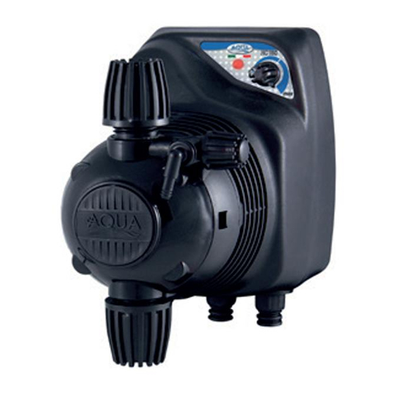
Analog solenoid driven dosing pump ENGLISH 1 INTRODUCTION Thank you for having purchased an Aqua product. The HC150 / HC101 series solenoid driven dosing pumps represent the ideal solution for dosing small amounts of chemical products. The pumps are regulated through analogue controls, including a two-colour LED and a regulating knob.
-
Page 5: Models
HC150 / HC101 INTRODUCTION Analog solenoid driven dosing pump ENGLISH There are 2 protection devices inside the pump: a varistor and a fuse. If it is necessary to remove the pump from the system, it is essential that the rubber discs are put back in so as to avoid liquid leaking out from the pump head.
-
Page 6: Standards Of Reference
HC150 / HC101 INTRODUCTION Analog solenoid driven dosing pump ENGLISH Flow Pressure Frequency (max) Flow Description cc per dose 0,28 HC101 Mod. 1 0,69 0,97 0,78 HC101 Mod. 2 0,89 1,11 0,33 HC101 Mod. 3 0,44 0,55 0,93 HC101 Mod. 4 1,11 1,30 0,44…
-
Page 7: Installation And Technical Features
HC150 / HC101 INSTALLATION Solenoid driven dosing pump ENGLISH 2.0 INSTALLATION AND TECHNICAL FEATURES 2.1 General regulations Pump installation must be carried out as follows: On a horizontal support (ex.: storage tank) or on the wall-mount bracket (optional) as long as the pumps remains in a vertical position +/- 15°.
-
Page 8: Pulse Emission Counter — Only For Model Pi
HC150 / HC101 INSTALLATION Solenoid driven dosing pump ENGLISH 2.3.3 Pulse Emission Counter – only for model PI HC150: Connect the red- BNC connector to the corresponding connector located at the bottom of the pump. HC150 PI Pulse water meter HC101: The pulse input is suitable for: …
-
Page 9: Hydraulic Connection
Overall dimensions HC150 series pump – wall-mounted (fig. 1) HC150 series pump – with base (fig. 2) HC101 series pump – with base (fig. 2a) Connections and exploded views …
-
Page 10: Programming The Pumps
HC150 / HC101 PROGRAMMING THE PUMPS Solenoid driven dosing pump ENGLISH 3 PROGRAMMING THE PUMPS 3.1 HC150 / HC101 costant Programming the HC150 / HC101 costant pump or in constant mode is based on the setting, using the knob, regulating the number of pulses per minute that the pump must carry out. It is possible to regulate the number of pulses per minute, and therefore the flow of the pump, using two regulating scales: …
-
Page 11: Hc150 / Hc101 Ma
HC150 / HC101 PROGRAMMING THE PUMPS Solenoid driven dosing pump ENGLISH 3.2 HC150 / HC101 mA The pump can operate in constant mode or in proportional current mode (mA). In constant mode it operates like model HC150 costant, whereas in proportional mode mA, the number of impulses is proportional to the current signal connected to the BNC — red connector.
-
Page 12: Scale Change Procedure
HC150 / HC101 PROGRAMMING THE PUMPS Solenoid driven dosing pump ENGLISH 3.2.2 Scale change procedure The following procedure allows you to switch from one scale to the other. To perform this operation it is advisable to use a medium flat-tip screwdriver. …
-
Page 13: Hc150 / Hc101 Pi
HC150 / HC101 PROGRAMMING THE PUMPS Solenoid driven dosing pump ENGLISH 3.3 HC150 / HC101 PI The pump can operate in constant mode as well as proportional mode to pulses sent from a counter. In constant mode it operates like model HC150 / HC101 costant whereas in proportional pulse mode the pump provides an injection for each “N”…
-
Page 14: Meaning Of Two-Colour Led
HC150 / HC101 PROGRAMMING THE PUMPS Solenoid driven dosing pump ENGLISH 2 flashes => 101…200 3 flashes => 201…300 1 flash => 1…100 until you reach: 10 flashes => 901…1000 and then to 1 flash green => 1…10 (1xN) 3.3.2 Meaning of two-colour LED The colour of the LED immediately indicates the type of proportional pump operation, in fact: …
-
Page 15: How To Choose The Pump
HC150 / HC101 PROGRAMMING THE PUMPS Solenoid driven dosing pump ENGLISH 3.3.4 How to choose the pump As the number of m of water to be treated in the system is known, and the quantity of product to be dosed, expressed in P.P.M.
-
Page 16: Maintenance
HC150 / HC101 MAINTENANCE Solenoid driven dosing pump ENGLISH 4 MAINTENANCE 4.1 General regulations Periodic maintenance is of fundamental importance to keep the pump in good running order and make it last over time. The tips provided below must be followed systematically and to the letter. It is extremely difficult to define the standard times required for maintenance beforehand, as the factors that determine the wear of the pump, and in particular the parts that are in contact with the liquid, are numerous.
-
Page 17: Troubleshooting
HC150 / HC101 MAINTENANCE Solenoid driven dosing pump ENGLISH 6. Re-insert the cartridge into the pump head. Changing sealing O-rings and the diaphragm Proceed as follows: 1. Remove the small round cover from the pump head using a small utensil to lever it off. 2.
-
Page 18: Chemical Compatibility Table
HC150 / HC101 WARRANTY Solenoid driven dosing pump ENGLISH 5 Chemical Compatibility Table Dosing pumps are widely used for dosing chemical products. It is important to select the most suitable material for the liquid to be dosed. The CHEMICAL COMPATIBILITY TABLE is a precious aid to that end. The following Table must be used as an indicative instrument.
-
Page 19: Return To The After-Sales Service
HC150 / HC101 WARRANTY Solenoid driven dosing pump ENGLISH Disclaimer The information included in these tables has been obtained from highly qualified sources which we deem reliable and they are provided without any guarantee, explicit or implicit, concerning their exactness. Conditions or methods for handling, storage and use of the material are beyond our control and/or knowledge.
-
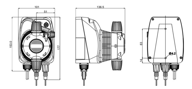
Page 20: Dimensioni — Dimensions
8 Dimensioni – Dimensions “HC150” – W . 1: S ERIE A MURO ALL MOUNTING “HC150” – B . 2: S ERIE CON BASE ASE MOUNTING ADSP9500090 Rev. 3.1 del 05/10/2020…
-
Page 21
ADSP9500090 Rev. 3.1 del 05/10/2020… -
Page 22
“HC101” – B . 2A: S ERIE CON BASE ASE MOUNTING ADSP9500090 Rev. 3.1 del 05/10/2020… -
Page 23
– P . 3: C OLLEGAMENTI TUBI SUL CORPO POMPA UMP HEAD CONNECTIONS – – L . 4: S . 5: C PURGO MANUALE MANUAL PURGE OLLEGAMENTO SONDA DI LIVELLO OW LEVEL PROBE — OPTIONAL CONNECTION ADSP9500090 Rev. 3.1 del 05/10/2020… -
Page 24: Esploso / Exploded View
9 Esploso / Exploded view Fig. 6: HC150 Esploso / Exploded view ADSP9500090 Rev. 3.1 del 05/10/2020…
-
Page 25
VITE M 2.9×13 UNI 6954 (TCTC) INOX A2 ADSP9500130 ANELLO IDENTIFICAZIONE INGRESSI BNC ADSP9000002 COVER GIALLO RAL 1007 CORPO POMPA 1-14LT HC897 ADSP9000003 TARGHETTA NERA CON LOGO AQUA PER CORPO POMPA 1-14LT HC897 ADSP6000749 VITE M 2.9X9.5 UNI 6954 (AF-TCTC) INOX A2 ADSP9500090 Rev. 3.1 del 05/10/2020… -
Page 26
ADSP9500130 BNC INPUTS IDENTIFICATION RING ADSP9000002 COVER YELLOW RAL 1007 PUMP HEAD 1-14LT HC897 ADSP9000003 BLACK PLATE WITH AQUA LOGO FOR PUMP HEAD 1-14LT HC897 M 2.9X9.5 UNI 6954 (AF-SLOTTED PAN HEAD SCREW) STAINLESS STEEL A2 ADSP6000749 SCREWS ADSP9500090 Rev. 3.1 del 05/10/2020… -
Page 27
Fig. 6A: HC101 Esploso / Exploded view ADSP9500090 Rev. 3.1 del 05/10/2020… -
Page 28
CORPO POMPA 1-14 PP-GL-VT COMPLETO HC897/797 31 ADSP9000002 COVER GIALLO RAL 1007 CORPO POMPA 1-14LT HC897 32 ADSP9000003 TARGHETTA NERA CON LOGO AQUA PER CORPO POMPA 1-14LT HC897 ADSP6000835 CONNETTORE MASCHIO 4 VIE G4A5M CABLATO SERVIZI 1XPANDUIT 2 VIE ADSP9500090… -
Page 29
PUMP HEAD 1-14 PP-GL-VT COMPLETE HC897/797 31 ADSP9000002 COVER YELLOW RAL 1007 PUMP HEAD 1-14LT HC897 32 ADSP9000003 BACKPLATE WITH AQUA LOGO FOR PUMP HEAD 1-14LT HC897 ADSP6000835 MALE CONNECTOR 4-WAY G4A5M CABLED SERVIZI 1XPANDUIT 2-WAY ADSP9500090 Rev. 3.1 del 05/10/2020… -
Page 30
Fig. 7: Corpo pompa e valvole a sfera – Pump head and ball valves ADSP9500090 Rev. 3.1 del 05/10/2020… -
Page 31
Descrizione / Description Codice Descrizione Q.tà ADSP9000001P CORPO POMPA 1-14 PVDF HC897 ADSP9000001 CORPO POMPA 1-14 PP HC897 ADSP5007200 OR — RIF. 3143 — VITON NERO ADSP5007209 OR — RIF. 3143 — DUTRAL NERO ADSP5007049V OR — RIF. 2010 — VITON NERO ADSP5007055D OR — RIF. -
Page 32
Descrizione / Description Code Description Q.ty ADSP9000001P PUMP HEAD 1-14 PVDF HC897 ADSP9000001 PUMP HEAD 1-14 PP HC897 ADSP5007200 OR — REF. 3143 — VITON BLACK ADSP5007209 OR — REF. 3143 — DUTRAL BLACK ADSP5007049V OR — RIF. 2010 — VITON BLACK ADSP5007055D OR — RIF. -
Page 33
Note on environmental protection After the implementation of the European Directive 2002/96/EU in the national legal system, the following applies: Electrical and electronic devices may not be disposed of with domestic waste. Consumers are obliged by lak to return electrical and electronic devices at the end of their service lives to the public collecting points set up for this purpose. -
Page 34
PUMPS SERIES HC150 ADSP9500090 Rev. 3.1 del 05/10/2020…
- Manuals
- Brands
- Aqua Manuals
- Water Pump
- HC150 Series
Manuals and User Guides for Aqua HC150 Series. We have 2 Aqua HC150 Series manuals available for free PDF download: Operating And Maintenance Instructions Manual, Manual
Aqua HC150 Series Operating And Maintenance Instructions Manual (151 pages)
Brand: Aqua
|
Category: Water Pump
|
Size: 4.96 MB
Table of Contents
-
Italiano
2
-
Table of Contents
2
-
1 Introduzione
4
-
Modelli
4
-
Portate Disponibili
5
-
Avvertenze
5
-
Normative DI Riferimento
5
-
Caratteristiche Tecniche
6
-
-
2 Installazione E Caratteristiche Tecniche
7
-
Norme Generali
7
-
Accessori in Dotazione
7
-
Collegamenti Elettrici
7
-
Alimentazione
7
-
Sonda DI Livello
7
-
Contatore Lancia Impulsi — solo Per Il Modello PI
8
-
Segnale in Corrente — solo Per Il Modello Ma
8
-
-
Collegamento Idraulico
8
-
Principio DI Funzionamento
9
-
-
3 Programmazione Delle Pompe
10
-
HC150 / HC101 Costante
10
-
Procedura Cambio Scala
10
-
Significato LED Bicolore
10
-
-
HC150 / HC101 Ma
11
-
Significato LED Bicolore
11
-
Procedura Cambio Scala
12
-
Cambio Modo DI Funzionamento
12
-
-
Hc150 / Hc101 Pi
13
-
Procedura Cambio Scala DI Intervallo
13
-
Significato LED Bicolore
14
-
Cambio Modo DI Funzionamento
14
-
Come Scegliere la Pompa
15
-
-
-
4 Manutenzione
16
-
Norme Generali
16
-
Manutenzione Periodica
16
-
Come Intervenire
16
-
Sostituzione Parti DI Normale Usura
16
-
Risoluzione Dei Problemi
17
-
-
5 Tabella DI Compatibilità Chimica
18
-
-
English
20
-
1 Introduction
22
-
Models
22
-
Available Flows
23
-
Warnings
23
-
Standards of Reference
23
-
Technical Features
24
-
-
2 Installation and Technical Features
25
-
General Regulations
25
-
Accessories Included
25
-
Electrical Connections
25
-
Power Supply
25
-
Low Level Probe
25
-
Pulse Emission Counter — Only for Model PI
25
-
Current Signal — Only for Model Ma
26
-
-
Hydraulic Connection
26
-
Principle of Operation
27
-
-
3 Programming the Pumps
28
-
HC150 / HC101 Costant
28
-
Scale Change Procedure
28
-
Meaning of Two-Colour LED
28
-
-
HC150 / HC101 Ma
29
-
Meaning of Two-Colour LED
29
-
Scale Change Procedure
30
-
How to Change the Operating Mode
30
-
-
Hc150 / Hc101 Pi
31
-
Interval Scale Change Procedure
31
-
Meaning of Two-Colour LED
32
-
How to Change the Operating Mode
32
-
How to Choose the Pump
33
-
How to Set the «N» Parameter in 1/N Mode
33
-
-
-
4 Maintenance
34
-
General Regulations
34
-
Periodic Maintenance
34
-
How to Intervene
34
-
How to Change Parts after Normal Wear
34
-
Troubleshooting
35
-
-
5 Chemical Compatibility Table
36
-
6 Return to the After-Sales Service
37
-
7 Guarantee Certificate
37
-
-
Français
38
-
1 Introduction
40
-
Modèles
40
-
Portées Disponibles
41
-
Notice D’utilisation
41
-
Réglementations de Référence
41
-
Caractéristiques Techniques
42
-
-
2 Installation Et Caracteristiques Techniques
43
-
Règles Générales
43
-
Accessoires en Dotation
43
-
Branchements Électriques
43
-
Alimentation
43
-
Sonde de Niveau
43
-
Compteur Émetteur Impulsions — Seulement Pour Le Modèle PI
44
-
Signal en Courant — Seulement Pour Le Modèle Ma
44
-
-
Raccordement Hydraulique
45
-
Principe de Fonctionnement
45
-
-
3 Programmation des Pompes
46
-
HC150 / HC101 Constant
46
-
Procédure Changement D’échelle
46
-
Signification LED Bicolore
46
-
-
HC150 / HC101 Ma
47
-
Signification LED Bicolore
47
-
Procédure Changement D’échelle
48
-
Changement Mode de Fonctionnement
48
-
-
Hc150 / Hc101 Pi
49
-
Procédure Changement D’échelle D’intervention
49
-
Signification LED Bicolore
50
-
Changement Mode de Fonctionnement
50
-
Comment Choisir la Pompe
51
-
Comment Régler Le Paramètre «N» en 1/N Mode
51
-
-
-
4 Entretien
52
-
Règles Générales
52
-
Entretien Périodique
52
-
Comment Intervenir
52
-
Remplacement Parties Usure Normale
52
-
Solutions des Problèmes
54
-
-
-
Español
57
-
Índice
58
-
1 Introducción
59
-
Modelos
59
-
Caudales Disponibles
60
-
Advertencias
60
-
Normativas de Referencia
60
-
Características Técnicas
61
-
-
2 Instalación y Características Técnicas
62
-
Normas Generales
62
-
Accesorios Suministrados
62
-
Conexiones Eléctricas
62
-
Alimentación
62
-
Sonda de Nivel
62
-
Contador Lanza Pulsaciones — solo para el Modelo PI
62
-
Señal en Corriente — solo para el Modelo Ma
63
-
-
Conexión Hidráulica
63
-
Principio de Funcionamiento
64
-
-
3 Programación de las Bombas
65
-
HC150 / HC101 Constante
65
-
Procedimiento del Cambio de Escala
65
-
Significado del Led Bicolor
65
-
-
HC150 / HC101 Ma
66
-
Significado del Led Bicolor
66
-
Procedimiento del Cambio de Escala
67
-
Cambio del Modo de Funcionamiento
67
-
-
Hc150 / Hc101 Pi
68
-
Procedimiento del Cambio de Escala de Intervalo
68
-
Significado del Led Bicolor
69
-
Cambio del Modo de Funcionamiento
69
-
Cómo Elegir la Bomba
70
-
Cómo Configurar el Parámetro «N» en 1 / N Modo
70
-
-
-
4 Mantenimiento
71
-
Normas Generales
71
-
Mantenimiento Periódico
71
-
Cómo Intervenir
71
-
Sustitución de las Piezas Sujetas a Desgaste Normal
71
-
Resolución de Problemas
72
-
-
-
Deutsch
75
-
1 Einführung
77
-
Modelle
77
-
Verfügbare Förderleistungen
78
-
Hinweise
78
-
Bezugsvorschriften
78
-
Technische Eigenschaften
79
-
-
2 Installation und Technische Eigenschaften
80
-
Allgemeine Vorschriften
80
-
Mitgeliefertes Zubehör
80
-
Elektrische Anschlüsse
80
-
Versorgung
80
-
Niveausonde
80
-
Impulsgeberzähler — nur Beim Modell PI
80
-
Stromsignal — nur bei Modell Ma
81
-
-
Hydraulischer Anschluss
81
-
Funktionsprinzip
82
-
-
3 Programmierung der Pumpen
83
-
HC150 / HC101 mit Konstanter Flussrate
83
-
Vorgehensweise zum Skalenwechsel
83
-
Bedeutung Zweifarb-LED
83
-
-
HC150 / HC101 Ma (mit Proportionaler Flussrate)
84
-
Bedeutung Zweifarb-LED
84
-
Vorgehensweise zum Skalenwechsel
85
-
Änderung des Betriebsmodus
85
-
-
Hc150 / Hc101 Pi
86
-
Vorgehensweise zum Wechseln der Intervallskala
86
-
Bedeutung Zweifarb-LED
87
-
Änderung des Betriebsmodus
87
-
Wahl der Pumpe
88
-
Einstellung des Parameters „N» in 1/N Modus
88
-
-
-
Allgemeine Vorschriften
89
-
Periodische Wartung
89
-
Vorgehensweise
89
-
Ersetzen von Verschleissteilen
89
-
Problembehebung
90
-
-
4 Wartung
89
-
-
Русский
110
-
1 Введение
112
-
Moдели
112
-
Важно Знать
113
-
Нормативы И Сертификаты
113
-
Технические Характеристики
113
-
-
2 Монтаж
114
-
Основные Требования
114
-
Комплектность Изделия
114
-
Электрические Характеристики
114
-
-
3 Узлы Насоса И Элементы Управления
114
-
Рисунок — ПАНЕЛЬ УПРАВЛЕНИЯ НАСОСОМ
115
-
Рисунок ГИДРАВЛИЧЕСКАЯ ЧАСТЬ
115
-
Принцип Работы
115
-
Гидравлические Соединения
117
-
МОНТАЖ ТРУБОК ЗАБОРНОЙ /НАПОРНОЙ К ПАТРУБКАМ ЗАБОРНОМУ И НАПОРНОМУ
117
-
Монтаж Трубок Заборной/Напорной К Внешним Заборному/Напорному Клапанам
117
-
Монтаж Линии Стравливания Воздуха
118
-
-
Электрические Соединения
119
-
Датчик Уровня-Подключение
119
-
Импульсный Водомер — Подключение — Только Для Моделей НС101 PI
119
-
Токовый Вход- Только Для Моделей НС101 Ma
119
-
-
-
4 Производительность
119
-
Производительность Электромагнитных Насосов
119
-
Кривые Производительности И Доступные Модификации
119
-
-
5 Программирование Насоса
121
-
HC101 CST -Постоянный
121
-
Процедура Смены Шкалы
121
-
Значения Двух Цветов Индикатора
121
-
-
HC101 Ma
122
-
Значения Двух Цветов Индикатора
122
-
Процедура Смены Шкалы
123
-
Смена Режима Дозирования
123
-
-
Hc101 Pi
124
-
Выбор И Смена Шкалы Интервалов
124
-
Значения Двух Цветов Индикатора
125
-
Смена Режима Дозирования
126
-
Как Выбрать Насос
126
-
-
-
Advertisement

Aqua HC150 Series Manual (34 pages)
Brand: Aqua
|
Category: Water Pump
|
Size: 3.05 MB
Table of Contents
-
Table of Contents
3
-
Introduction
4
-
Warnings
4
-
Models
5
-
Available Flows
5
-
Standards of Reference
6
-
Technical Features
6
-
Installation and Technical Features
7
-
General Regulations
7
-
Accessories Included
7
-
Electrical Connections
7
-
Power Supply
7
-
Low Level Probe
7
-
Pulse Emission Counter — Only for Model PI
8
-
Current Signal — Only for Model Ma
8
-
Hydraulic Connection
9
-
Principle of Operation
9
-
Programming the Pumps
10
-
HC150 / HC101 Costant
10
-
Scale Change Procedure
10
-
Meaning of Two-Colour LED
10
-
HC150 / HC101 Ma
11
-
Meaning of Two-Colour LED
11
-
Scale Change Procedure
12
-
How to Change the Operating Mode
12
-
Hc150 / Hc101 Pi
13
-
Interval Scale Change Procedure
13
-
Meaning of Two-Colour LED
14
-
How to Change the Operating Mode
14
-
How to Choose the Pump
15
-
Maintenance
16
-
General Regulations
16
-
Periodic Maintenance
16
-
How to Intervene
16
-
How to Change Parts after Normal Wear
16
-
Troubleshooting
17
-
Chemical Compatibility Table
18
-
Return to the After-Sales Service
19
-
Guarantee Certificate
19
-
Dimensioni — Dimensions
20
-
Esploso / Exploded View
24
Advertisement
Related Products
-
Aqua HC150 costant
-
Aqua HC150 mA
-
Aqua HC150 PI
-
Aqua HC150 0
-
Aqua HC150 1
-
Aqua HC150 2
-
Aqua HC150 3
-
Aqua HC150 4
-
Aqua HC150 5
-
Aqua HC151
Aqua Categories
Water Pump
Water Filtration Systems
![]()
Indoor Furnishing
Lighting Equipment
Bathroom Fixtures
More Aqua Manuals
Operating And Maintenance Instructions Manual for Aqua HC150 Series Water Pump (151 pages)
Specifications:1517/1517040-hc150_series.pdf file (09 May 2023) |
Accompanying Data:
Aqua HC150 Series Water Pump PDF Operating And Maintenance Instructions Manual (Updated: Tuesday 9th of May 2023 05:50:18 AM)
Rating: 4.8 (rated by 57 users)
Compatible devices: HC 200, Simpool Pool-T, DET 1, TEXMO AHS 02/03, HC151 PH-RX, HC997-1, HC 1, ECO WASH.
Recommended Documentation:
Text Version of Operating And Maintenance Instructions Manual
(Ocr-Read Summary of Contents of some pages of the Aqua HC150 Series Document (Main Content), UPD: 09 May 2023)
-
69, HC150 / HC101 MANTENIMIENTO Bomba dosificadora electromagnética ESPAÑOL ADSP9500090 Rev.2.5 09.09.2015 69 1 parpadeo => 1…100 2 parpadeos => 101…200 3 parpadeos => 201…300 hasta llegar a: 10 parpadeos => 901…1000 y luego a 1 parpadeo verde => 1 … 1…
-
79, Aqua HC150 Series HC150 / HC101 EINFÜHRUNG Analoge elektromagnetische Dosierpumpe DEUTSCH ADSP9500090 Rev.2.5 09.09.2015 79 n° 2004/108/CE “ e s.m.i. n° 2006/95/CE “DBT Low Voltage Directive” e s.m.i. n° 2011/65/UE , 2002/96/CE “direttive RoHs e WEEE” e s.m.i. Dies vo…
-
20, HC150 / HC101 INDEX Analog solenoid driven dosing pump ENGLISH ADSP9500090 Rev.2.5 09.09.2015 20 CONTENTS 1 INTRODUCTION ……………………………………………………………………………………………………………………….. 22 1.1 Models …………………..…
-
82, HC150 / HC101 PROGRAMMIERUNG DER PUMPEN Elektromagnetische Dosierpumpe DEUTSCH ADSP9500090 Rev.2.5 09.09.2015 82 das Produkt injiziert werden soll, ein Verbindungsstück des Typs 1/2” Gf angebracht wurde, das Injektionsventil mit Teflon umwickeln und in die Rohrleitung stecken. Gewinder…
-
148, Aqua HC150 Series ADSP9500090 Rev.2.5 09.09.2015 148 Descrizione / Description / Description / Descripción / Beschreibung # Código Descripción Cant. 2 ADSP9000001P CUERPO DE LA BOMBA 1-14 PVDF HC897 1 ADSP9000001 CUERPO DE LA BOMBA 1-14 PP HC897 1 3 ADSP5007200 JUNTA TÓRICA — REF. 314…
-
28, HC150 / HC101 PROGRAMMING THE PUMPS Solenoid driven dosing pump ENGLISH ADSP9500090 Rev.2.5 09.09.2015 28 3 PROGRAMMING THE PUMPS 3.1 HC150 / HC101 costant Programming the HC150 / HC101 costant pump or in constant mode is based on the setting, using the knob, regulating the numbe…
-
Aqua HC150 Series User Manual
-
Aqua HC150 Series User Guide
-
Aqua HC150 Series PDF Manual
-
Aqua HC150 Series Owner’s Manuals
Recommended: ICF-CD855V, RX Series, HT702


-
Simer SIMER 2961
OWNER’S MANUALSubmersible Solids Handling PumpsNOTICE D’UTILISATIONPompes submersibles pour les matières solidesMANUAL DEL USUARIOBombas submergibles para elmanejo de líquidos con sólidosInstallation/Operation/PartsFor further operating, installation, or maintenance assistance: Call 1-800-468-7867E …
SIMER 2961 16
-
Sandpiper S30
Model S30 Non-Metallic Design Level 3A Unit of IDEX Corporation800 N. Main St., Manseld, Ohio 44902 USA Telephone 419.524.8388Fax 419.522.7867SANDPIPERPUMP.COM© Copyright 2017 Warren Rupp, Inc.All righ …
S30 24
-
Zehnder Pumpen ZKH 20
[de] Kondensatpumpe — Installations- und Wartungsanleitung für den Fachhandwerker [fr] Pompe à condensats — Notice d’installation et d’entretien pour le professionnel[en] Condensate pump — Installation and Maintenance Instructions for the Contractor [cz] Čerpadlo kondenzátu — Návod k in …
ZKH 20 16
-
Edelbrock 63-0303
©2010 Edelbrock Corporation Part #8810-8812, 88104, 88114, 88124, 8816, 8817, 8820-8822Rev. 3/10 — AJ/mc Page 1 of 3 Brochure #63-0303PLEASE study these instructions carefully before installing your new water pump. If you have any questions or problems, do not hesitate to contactour Technical Hotline …
63-0303 3
Popular Right Now:
Operating Impressions, Questions and Answers:

| МАТЕРИАЛ ИСПОЛНЕНИЯ | ||
|---|---|---|
| Насос AQUA HC 150 | Стандартное исполнение | По запросу |
| Головка насоса | PP | PVDF |
| Мембрана | PTFE | – |
| Шаровые клапаны | Pyrex | PTFE, Ceramica |
| Фитинги | PP | PVDF |
| Уплотнения | Viton | Dutral |
| Пружина инжкционного клапана | Hastelloy-Pyrex | Hastelloy-PTFE-Ceramica |
| Инжектор | PP | PVDF |
| Донные клапаны | PP | PVDF |
| ДОСТУПНЫЕ ВЕРСИИ | |
|---|---|
| Тип | Аналоговый |
| Регулировка производительности | Регулировка производительности (кол-во тактов) |
| Постоянное дозирование | • AQUA HC 150 CST |
| Пропорционально водосчетчику | • AQUA HC 150 PI |
| Пропорционлаьно сигналу 4-20 мА | • AQUA HC 150 MA |
| Подключение датчика уровня | • |
| Подключение датчика потока | no |
| Подключение датчика PH-RX | no |
| Подключение датчика CL | no |
| ГИДРАВЛИЧЕСКИЕ ХАРАКТЕРИСТИКИ | |||||||
|---|---|---|---|---|---|---|---|
| Модель | Производительность л/ч | Давление BAR | Количество тактов в минуту | Обьем впрыска мл | Потребление ВАТТ | Трубка мм | Головка насоса |
| 0 | 1,5 | 5 | 100 | 0,25 | 14 | 4×6 | PP 1/2″ |
| 2 | 3 | 0,33 | |||||
| 3 | 1 | 0,50 | |||||
| 1 | 2 | 8 | 120 | 0,28 | 14 | 4×6 | PP 1/2″ |
| 5 | 5 | 0,69 | |||||
| 7 | 2 | 0,97 | |||||
| 2 | 7 | 4 | 150 | 0,78 | 14 | 4×6 | PP 1/2″ |
| 8 | 2 | 0,89 | |||||
| 10 | 0 | 1,11 | |||||
| 3 | 3 | 12 | 120 | 0,42 | 16 | 4×6 | PP 1/2″ |
| 4 | 10 | 0,56 | |||||
| 5 | 8 | 0,69 | |||||
| 4 | 10 | 4 | 180 | 0,93 | 16 | 4×6 | PP 1/2″ |
| 12 | 2 | 1,11 | |||||
| 14 | 0 | 1,30 | |||||
| 5 | 2 | 20 | 75 | 0,44 | 16 | 4×6 | PP 1/2″ |
| 2,5 | 18 | 0,56 | |||||
| 3 | 15 | 0,67 |
| КОМПЛЕКТ ПОСТАВКИ | |
|---|---|
| Насос Aqua HC 150 | |
| ADSP6000001 | Донный клапан всасывания |
| ADSP6200007 | Инжекционный клапан |
| ADSP6000546 | Трубка всасывающая PVС (2м) |
| ADSP6000078 | Трубка подающая PE (2м) |
| ADSP6020221 | Кронштейн крепежный на стену |
| ADSP6000041 | Крепежная фурнитура |
| Инструкция |
