
142
ASRock 970 Extreme4 Motherboard
1. Введение
Благодарим вас за покупку материнской платы ASRock 970 Extreme4 надежной
материнской платы, изготовленной в соответствии с постоянно предъявляемыми ASRock
жесткими требованиями к качеству. Она обеспечивает превосходную производительность
и отличается отличной конструкцией, которые отражают приверженность ASRock качеству
и долговечности.
Данное руководство по быстрой установке включает вводную информацию о материнской
плате и пошаговые инструкции по ее установке. Более подробные сведения о плате
можно найти в руководстве пользователя на компакт-диске поддержки.
Спецификации материнской платы и программное обеспечение
BIOS
иногда изменяются, поэтому содержание этого руководства
может обновляться без уведомления. В случае любых
модификаций руководства его новая версия будет размещена на
веб-сайте ASRock без специального уведомления. Кроме того,
самые свежие списки поддерживаемых модулей памяти и
процессоров можно найти на сайте ASRock.
Адрес веб-сайта ASRock http://www.asrock.com
При необходимости технической поддержки по вопросам данной
материнской платы посетите наш веб-сайт для получения
информации об используемой модели.
www.asrock.com/support/index.asp
1.1 Комплектность
Материнская плата ASRock 970 Extreme4
(форм-фактор ATX: 12,0 x 9,6 дюйма / 30,5 x 24,4 см)
Руководство по быстрой установке ASRock 970 Extreme4
Компакт-диск поддержки ASRock 970 Extreme4
4 x кабель данных Serial ATA (SATA) (дополнительно)
1 x аудиокабель с 3,5-мм штекерами (дополнительно)
1 x I/O Щит Группы ввода / вывода
1 x карта ASRock SLI_Bridge_2S
ASRock напоминает…
Для обеспечения максимальной производительности ОС Windows
®
7 / 7 64-bit / Vista
TM
/ Vista
TM
64-bit рекомендуется в BIOS выбрать для
параметра Storage Configuration (Конфигурация запоминающего
устройства) режим AHCI. Подробные сведения о настройке BIOS см.
в руководстве пользователя на прилагаемом компакт-диске.
Ру
сский
-
Contents
-
Table of Contents
-
Bookmarks
Quick Links
970 Extreme4
User Manual
Version 1.0
Published May 2011
Copyright©2011 ASRock INC. All rights reserved.
1
Related Manuals for ASROCK 970 Extreme4
Summary of Contents for ASROCK 970 Extreme4
-
Page 1: User Manual
970 Extreme4 User Manual Version 1.0 Published May 2011 Copyright©2011 ASRock INC. All rights reserved.
-
Page 2: Copyright Notice
In no event shall ASRock, its directors, of f cers, employees, or agents be liable for any indirect, special, incidental, or consequential damages (including damages for…
-
Page 3: Table Of Contents
CrossFireX , 3-Way CrossFireX and Quad CrossFireX Operation Guide ……………. 23 Surround Display Information ………… 28 ASRock Smart Remote Installation Guide ……… 29 Jumpers Setup …………….30 2.10 Onboard Headers and Connectors ……..31 2.11 Smart Switches …………….36 2.12 Dr. Debug …………….
-
Page 4
3. UEFI SETUP UTILITY…………48 Introduction …………….48 3.1.1 UEFI Menu Bar …………..48 3.1.2 Navigation Keys …………… 49 Main Screen …………….49 OC Tweaker Screen…………..50 Advanced Screen …………..54 3.4.1 CPU Conf guration …………55 3.4.2 North Bridge Conf guration ……….56 3.4.3 South Bridge Conf guration ………. -
Page 5: Introduction
In case any modi f cations of this manual occur , the updated ver- sion will be available on ASRock website without further notice. You may f nd the latest VGA cards and CPU support lists on ASRock website as well. ASRock website http://www.asrock.com…
-
Page 6: Specifications
1.2 Specifications — ATX Form Factor: 12.0-in x 9.6-in, 30.5 cm x 24.4 cm Platform — All Solid Capacitor design (100% Japan-made high-quality Conductive Polymer Capacitors) — Support for Socket AM3+ processors — Support for Socket AM3 processors: AMD Phenom II X6 / X4 / X3 / X2 (except 920 / 940) / Athlon II X4 / X3 / X2 / Sempron processors…
-
Page 7
— Supports Energy Eff cient Ethernet 802.3az — Supports PXE I/O Panel Rear Panel I/O — 1 x PS/2 Mouse Port — 1 x PS/2 Keyboard Port — 1 x Coaxial SPDIF Out Port — 1 x Optical SPDIF Out Port — 4 x Ready-to-Use USB 2.0 Ports — 2 x Ready-to-Use USB 3.0 Ports — 1 x eSATA3 Connector… -
Page 8
Certifi cations — ErP/EuP Ready (ErP/EuP ready power supply is required) (see CAUTION 15) * For detailed product information, please visit our website: http://www.asrock.com WARNING Please realize that there is a certain risk involved with overclocking, including adjusting the setting in the BIOS, applying Untied Overclocking Technology, or using the third-party over- clocking tools. -
Page 9
CAUTION! ASRock UCC (Unlock CPU Core) feature simplif es AMD CPU activa- tion. As long as a simple switch of the UEFI option “ASRock UCC”, you can unlock the extra CPU core to enjoy an instant performance boost. When UCC feature is enabled, the dual-core or triple-core CPU will boost… -
Page 10
ASRock Instant Flash is a BIOS f ash utility embedded in Flash ROM. This convenient BIOS update tool allows you to update system BIOS ® without entering operating systems f rst like MS-DOS or Windows . With this utility, you can press <F6> key during the POST or press <F2> key to BIOS setup menu to access ASRock Instant Flash. -
Page 11
it back again. To improve heat dissipation, remember to spray thermal grease between the CPU and the heatsink when you install the PC sys- tem. 15. EuP, stands for Energy Using Product, was a provision regulated by Eu- ropean Union to def ne the power consumption for the completed system. According to EuP, the total AC power of the completed system shall be under 1.00W in off mode condition. -
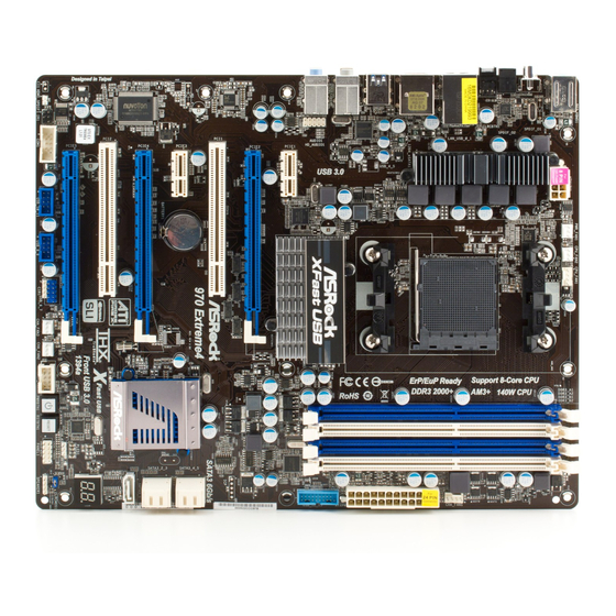
Page 12: Motherboard Layout
USB 2.0 T: USB2 B: USB3 USB 3.0 T: USB4 B: USB5 HD_AUDIO1 Chipset PCIE1 PCIE2 AUDIO CODEC PCI1 SATA3 6Gb/s 970 Extreme4 CMOS BATTERY PCIE3 SB950 Chipset Super PCIE4 SATA3_1 PCI2 FAST USB 32Mb Debug BIOS Front USB 3.0…
-
Page 13: I/O Panel
1.4 I/O Panel PS/2 Mouse Port (Green) USB 3.0 Port (USB45) LAN RJ-45 Port IEEE 1394 Port (IEEE 1394) USB 2.0 Ports (USB23) *** 12 eSATA3 Connector Side Speaker (Gray) USB 2.0 Ports (USB01) Rear Speaker (Black) Clear CMOS Switch (CLRCBTN) Central / Bass (Orange) Optical SPDIF Out Port Line In (Light Blue)
-
Page 14
To enable Multi-Streaming function, you need to connect a front panel audio cable to the front panel audio header. After restarting your computer, you will f nd “Mixer” tool on your system. Please select “Mixer ToolBox” , click “Enable playback multi-streaming”, and click “ok”. Choose “2CH”, “4CH”, “6CH”, or “8CH”… -
Page 15: Installation
2. Installation This is an ATX form factor (12.0-in x 9.6-in, 30.5 cm x 24.4 cm) motherboard. Before you install the motherboard, study the conf guration of your chassis to ensure that the motherboard f ts into it. Pre-installation Precautions Take note of the following precautions before you install motherboard components or change any motherboard settings.
-
Page 16: Cpu Installation
2.1 CPU Installation Step 1. Unlock the socket by lifting the lever up to a 90 angle. Step 2. Position the CPU directly above the socket such that the CPU corner with the golden triangle matches the socket corner with a small triangle. Step 3.
-
Page 17: Installation Of Memory Modules (Dimm)
2.3 Installation of Memory Modules (DIMM) This motherboard provides four 240-pin DDR3 (Double Data Rate 3) DIMM slots, and supports Dual Channel Memory Technology. For dual channel conf guration, you always need to install identical (the same brand, speed, size and chip-type) DDR3 DIMM pair in the slots of the same color .
-
Page 18: Installing A Dimm
Installing a DIMM Please make sure to disconnect power supply before adding or removing DIMMs or the system components. Step 1. Unlock a DIMM slot by pressing the retaining clips outward. Step 2. Align a DIMM on the slot such that the notch on the DIMM matches the break on the slot.
-
Page 19: Expansion Slots (Pci And Pci Express Slots)
2.4 Expansion Slots (PCI and PCI Express Slots) There are 2 PCI slots and 5 PCI Express slots on this motherboard. PCI Slots: PCI slots are used to install expansion cards that have the 32-bit PCI interface. PCIE Slots: PCIE1 / PCIE3 (PCIE x1 slot; White) is used for PCI Express cards with x1 lane width cards, such as Gigabit LAN card and SATA2 card.
-
Page 20: Sli Tm Operation Guide
2.5 SLI Operation Guide ® This motherboard supports NVIDIA technology (Scalable Link Interface) that allows you to install up to three identical PCI Express x16 graphics cards. Currently , ® ® NVIDIA technology supports Windows XP / XP 64-bit / V ista / Vista bit / 7 / 7 64-bit OS.
-
Page 21: Driver Installation And Setup
Step3. Align and insert ASRock SLI_Bridge_2S Card to the gold f ngers on each graphics card. Make sure ASRock SLI_Bridge_2S Card is f rmly in place. ASRock SLI_Bridge_2S Card Step4. Connect a VGA cable or a DVI cable to the monitor connector or the DVI connector of the graphics card that is inserted to PCIE2 slot.
-
Page 22
® For Windows Vista / Vista 64-bit / 7 / 7 64-bit OS: A. Click the Start icon on your Windows taskbar. B. From the pop-up menu, select All Programs, and then click NVIDIA Corporation. C. Select NVIDIA Control Panel tab. D. -
Page 23: Tm Tm Tm
2.6 CrossFireX , 3-Way CrossFireX and Quad CrossFireX Operation Guide This motherboard supports CrossFireX , 3-way CrossFireX and Quad CrossFireX feature. CrossFireX technology offers the most advantageous means available of combining multiple high performance Graphics Processing Units (GPU) in a single PC. Combining a range of dif ferent operating modes with intelligent software design and an innovative interconnect mechanism, CrossFireX enables the highest possible level of performance and image quality in any 3D…
-
Page 24
Step 2. Connect two Radeon graphics cards by installing CrossFire Bridge on CrossFire Bridge Interconnects on the top of Radeon graphics cards. (CrossFire Bridge is provided with the graphics card you purchase, not bundled with this motherboard. Please refer to your graphics card vendor for details.) CrossFire Bridge Step 3. -
Page 25
2.6.1.2 Installing Three CrossFireX -Ready Graphics Cards Step 1. Install one Radeon graphics card to PCIE2 slot. For the proper installation procedures, please refer to section “Expansion Slots”. Step 2. Install one Radeon graphics card to PCIE4 slot. For the proper installation procedures, please refer to section “Expansion Slots”. -
Page 26
CrossFire Bridge Step 5. Connect the DVI monitor cable to the DVI connector on the Radeon graph- ics card on PCIE2 slot. (You may use the DVI to D-Sub adapter to convert the DVI connector to D-Sub interface, and then connect the D-Sub monitor cable to the DVI to D-Sub adapter.) -
Page 27
2.6.2 Driver Installation and Setup Step 1. Power on your computer and boot into OS. Step 2. Remove the AMD driver if you have any VGA driver installed in your sys- tem. The Catalyst Uninstaller is an optional download. We recommend using this utility to uninstall any previously installed Catalyst drivers prior to installation. -
Page 28: Surround Display Information
Although you have selected the option “Enable CrossFire ”, the Cross- FireX function may not work actually. Your computer will automatically reboot. After restarting your computer, please conf rm whether the option “Enable CrossFire ” in “ATI Catalyst Control Center” is selected or not; if not, please select it again, and then you are able to enjoy the bene f t of CrossFireX…
-
Page 29: Asrock Smart Remote Installation Guide
The Multi-Angle CIR Receiver does not support Hot-Plug function. Please install it before you boot the system. * ASRock Smart Remote is only supported by some of ASRock motherboards. Please refer to ASRock website for the motherboard support list: http://www.asrock.com…
-
Page 30: Jumpers Setup
2.9 Jumpers Setup The illustration shows how jumpers are setup. When the jumper cap is placed on pins, the jumper is “Short”. If no jumper cap is placed on pins, the jumper is “Open”. The illustration shows a 3-pin jumper whose pin1 and pin2 are “Short”…
-
Page 31: Onboard Headers And Connectors
2.10 Onboard Headers and Connectors Onboard headers and connectors are NOT jumpers. Do NOT place jumper caps over these headers and connectors. Placing jumper caps over the headers and connectors will cause permanent damage of the motherboard! Serial ATA3 Connectors These f ve Serial ATA3 (SATA3) connectors support (SATA3_1: see p.12, No.
-
Page 32
(9-pin USB_8_9) (see p.12 No. 29) (9-pin USB_10_11) (see p.12 No. 30) USB 3.0 Header Besides two default USB 3.0 ports on the I/O panel, there is (19-pin USB_12_13) one USB 3.0 header on this (see p.12 No. 11) motherboard. This USB 3.0 header can support two USB 3.0 ports. -
Page 33
1. High Def nition Audio supports Jack Sensing, but the panel wire on the chassis must support HDA to function correctly. Please follow the instruction in our manual and chassis manual to install your system. 2. If you use AC’97 audio panel, please install it to the front panel audio header as below: A. -
Page 34
The front panel design may differ by chassis. A front panel module mainly consists of power switch, reset switch, power LED, hard drive activity LED, speaker and etc. When connecting your chassis front panel module to this header, make sure the wire assignments and the pin assign-ments are matched correctly. -
Page 35
Though this motherboard provides 4-Pin CPU fan (Quiet Fan) support, the 3-Pin CPU fan still can work successfully even without the fan speed control function. If you plan to connect the 3-Pin CPU fan to the CPU fan connector on this motherboard, please connect it to Pin 1-3. -
Page 36: Smart Switches
Serial port Header This COM1 header supports a serial port module. (9-pin COM1) (see p.12 No.31) HDMI_SPDIF Header HDMI_SPDIF header, providing SPDIF audio output to HDMI (2-pin HDMI_SPDIF1) VGA card, allows the system to see p.12 No. 33) connect HDMI Digital TV/ projector/LCD devices.
-
Page 37: Dr. Debug
2.12 Dr. Debug Dr. Debug is used to provide code information, which makes troubleshooting even easier. Please see the diagrams below for reading the Dr. Debug codes. Status Code Description 0x00 Not used 0x01 Power on. Reset type detection (soft/hard) 0x02 AP initialization before microcode loading 0x03…
-
Page 38
0x37 Post-Memory North Bridge initialization is started 0x38 Post-Memory North Bridge initialization (North Bridge module specif c) 0x39 Post-Memory North Bridge initialization (North Bridge module specif c) 0x3A Post-Memory North Bridge initialization (North Bridge module specif c) 0x3B Post-Memory South Bridge initialization is started 0x3C Post-Memory South Bridge initialization (South Bridge module specif c) 0x3D… -
Page 39
0x62 Installation of the South Bridge Runtime Services 0x63 CPU DXE initialization is started 0x64 CPU DXE initialization (CPU module specif c) 0x65 CPU DXE initialization (CPU module specif c) 0x66 CPU DXE initialization (CPU module specif c) 0x67 CPU DXE initialization (CPU module specif c) 0x68 PCI host bridge initialization 0x69… -
Page 40
0xA6 SCSI Detect 0xA7 SCSI Enable 0xA8 Setup Verifying Password 0xA9 Start of Setup 0xAA Reserved for ASL (see ASL Status Codes section below) 0xAB Setup Input Wait 0xAC Reserved for ASL (see ASL Status Codes section below) 0xAD Ready To Boot event 0xAE Legacy Boot event 0xAF… -
Page 41: Serial Ata3 (Sata3) Hard Disks Installation
2.13 Serial ATA3 (SATA3) Hard Disks Installation This motherboard adopts AMD SB950 chipset that supports Serial ATA3 (SATA3) hard disks and RAID (RAID 0, RAID 1, RAID 0+1, JBOD and RAID 5) functions. You may install SATA3 hard disks on this motherboard for internal storage devices. This section will guide you to install the SATA3 hard disks.
-
Page 42: Sata3 Hdd Hot Plug Feature And Operation Operation Guide
* The SATA3 Hot Plug feature might not be supported by the chipset because of its limitation, the SATA3 Hot Plug support information of our motherboard is indicated in the product spec on our website: www.asrock.com 2. Make sure your SATA3 HDD can support Hot Plug function from your dealer or HDD user manual.
-
Page 43
How to Hot Plug a SATA3 HDD: Points of attention, before you process the Hot Plug: Please do follow below instruction sequence to process the Hot Plug, improper procedure will cause the SATA3 HDD damage and data loss. Please connect SATA power cable 1×4-pin Step 1 Connect SATA data cable to Step 2… -
Page 44: Driver Installation Guide
STEP 2: Make a SATA3 Driver Diskette. (Please use USB fl oppy or fl oppy disk.) A. Insert the ASRock Support CD into your optical drive to boot your system. B. During POST at the beginning of system boot-up, press <F11> key, and then a window for boot devices selection appears.
-
Page 45: With Raid Functions
STEP 3: Use “RAID Installation Guide” to set RAID confi guration. Before you start to conf gure RAID function, you need to check the RAID installation guide in the Support CD for proper con f guration. Please refer to the BIOS RAID installation guide part of the document in the following path in the Support CD: ..
-
Page 46: Xp 64-Bit Without Raid Functions
® 2.18 Installing Windows 7 / 7 64-bit / Vista Vista 64-bit / XP / XP 64-bit Without RAID Functions ® If you want to install Windows 7 / 7 64-bit / V ista / Vista 64-bit / XP / XP 64-bit OS on your SA TA3 HDDs without RAID functions, please follow below procedures according to the OS you install.
-
Page 47: Without Raid Functions
® 2.18.2 Installing Windows 7 / 7 64-bit / Vista Vista 64-bit Without RAID Functions ® If you want to install Windows 7 / 7 64-bit / V ista / Vista 64-bit on your SA TA3 HDDs without RAID functions, please follow below steps. Using SATA3 HDDs with NCQ and Hot Plug functions (AHCI mode) STEP 1: Set up UEFI.
-
Page 48: Uefi Setup Utility
3. UEFI SETUP UTILITY 3.1 Introduction This section explains how to use the UEFI SETUP UTILITY to conf gure your sys- tem. The SPI Memory on the motherboard stores the UEFI SETUP UTILITY. You may run the UEFI SETUP UTILITY when you start up the computer . Please press <F2>…
-
Page 49: Navigation Keys
3.1.2 Navigation Keys Please check the following table for the function description of each navigation key. Navigation Key(s) Function Description Moves cursor left or right to select Screens Moves cursor up or down to select items To change option for the selected items + / — To bring up the selected screen <Enter>…
-
Page 50: Oc Tweaker Screen
ASRock UCC ASRock UCC (Unlock CPU Core) feature simpli f es AMD CPU activation. As long as a simple switch of the UEFI option “ASRock UCC”, you can unlock the extra CPU core to enjoy an instant performance boost. When…
-
Page 51
Multiplier/Voltage Change This item is set to [Auto] by default. If it is set to [Manual], you may adjust the value of Processor Frequency and Processor Voltage. However, it is recommended to keep the default value for system stability. HT Bus Speed This feature allows you selecting Hyper-T ransport bus speed. -
Page 52
CAS# Latency (tCL) Use this item to change CAS# Latency (tCL) Auto/Manual setting. The default is [Auto]. RAS# to CAS# Delay (tRCD) Use this item to change RAS# to CAS# Delay (tRCD) Auto/Manual setting. The default is [Auto]. Row Precharge Time (tRP) Use this item to change Row Precharge Time (tRP) Auto/Manual setting. -
Page 53
NB Voltage Use this to select NB Voltage. The default value is [Auto]. HT Voltage Use this to select HT Voltage. The default value is [Auto]. CPU VDDA Voltage Use this to select CPU VDDA Voltage. The default value is [Auto]. PCIE VDDA Voltage Use this to select PCIE VDDA Voltage. -
Page 54: Advanced Screen
3.4 Advanced Screen In this section, you may set the con f gurations for the following items: CPU Con f gu- ration, Nouth Bridge Con f guration, South Bridge Con f guration, Storage Conf gura- tion, Super IO Conf guration, ACPI Conf guration, and USB Conf guration. Setting wrong values in this section may cause the system to malfunction.
-
Page 55: Cpu Configuration
3.4.1 CPU Configuration Cool ‘n’ Quiet Use this item to enable or disable AMD’s Cool ‘n’ Quiet technology. The default value is [Enabled]. Conf guration options: [Enabled] and [Disabled]. ® If you install Windows 7 / Vista and want to enable this function, please set this item to [Enabled].
-
Page 56: North Bridge Configuration
3.4.2 North Bridge Configuration Primary Graphics Adapter This item will switch the PCI Bus scanning order while searching for video card. It allows you to select the type of Primary VGA in case of multiple video controllers. The default value of this feature is [PCI Express]. Con- f guration options: [PCI] and [PCI Express].
-
Page 57: South Bridge Configuration
3.4.3 South Bridge Configuration Onboard HD Audio Select [Auto], [Enabled] or [Disabled] for the onboard HD Audio feature. If you select [Auto], the onboard HD Audio will be disabled when PCI Sound Card is plugged. Front Panel Select [Auto] or [Disabled] for the onboard HD Audio Front Panel. On/Off Play Use this item to enable or disable On/Off Play Technology.
-
Page 58: Storage Configuration
3.4.4 Storage Configuration SATA Controller Use this item to enable or disable the “SATA Controller” feature. SATA Mode Use this item to adjust SATA Mode. The default value of this option is [IDE Mode]. Conf guration options: [AHCI Mode], [RAID Mode] and [IDE Mode]. If you set this item to RAID mode, it is suggested to install SATA ODD driver on SATA3_5 and eSATA3 ports.
-
Page 59: Super Io Configuration
3.4.5 Super IO Configuration Serial Port Use this item to enable or disable the onboard serial port. Serial Port Address Use this item to set the address for the onboard serial port. Con f guration options: [3F8h / IRQ4] and [3E8h / IRQ4]. Infrared Port Use this item to enable or disable the onboard infrared port.
-
Page 60: Acpi Configuration
3.4.6 ACPI Configuration Suspend to RAM Use this item to select whether to auto-detect or disable the Suspend-to- RAM feature. Select [Auto] will enable this feature if the OS supports it. Check Ready Bit Use this item to enable or disable the feature Check Ready Bit. Restore on AC/Power Loss This allows you to set the power state after an unexpected AC/power loss.
-
Page 61
USB Mouse Power On Use this item to enable or disable the system to wake from S5 using USB Mouse. ACPI HPET table Use this item to enable or disable ACPI HPET Table. The default value is [Enabled]. Please set this option to [Enabled] if you plan to use this moth- ®… -
Page 62: Usb Configuration
3.4.7 USB Configuration USB 2.0 Controller Use this item to enable or disable the use of USB 2.0 controller. USB 3.0 Controller Use this item to enable or disable the use of USB 3.0 controller. Legacy USB Support Use this option to select legacy support for USB devices. There are four conf guration options: [Enabled], [Auto], [Disabled] and [UEFI Setup Only].
-
Page 63: Hardware Health Event Monitoring Screen
3.5 Hardware Health Event Monitoring Screen In this section, it allows you to monitor the status of the hardware on your system, including the parameters of the CPU temperature, motherboard temperature, CPU fan speed, chassis fan speed, and the critical voltage. CPU Fan 1 &…
-
Page 64: Boot Screen
3.6 Boot Screen In this section, it will display the available devices on your system for you to con f g- ure the boot settings and the boot priority. Setup Prompt Timeout This shows the number of seconds to wait for setup activation key. 65535(0xFFFF) means indef nite waiting.
-
Page 65: Security Screen
3.7 Security Screen In this section, you may set or change the supervisor/user password for the system. For the user password, you may also clear it.
-
Page 66: Exit Screen
3.8 Exit Screen Save Changes and Exit When you select this option, it will pop-out the following message, “Save conf guration changes and exit setup?” Select [OK] to save the changes and exit the UEFI SETUP UTILITY. Discard Changes and Exit When you select this option, it will pop-out the following message, “Discard changes and exit setup?”…
-
Page 67: Software Support
Click on a specif c item then follow the installation wizard to install it. 4.2.4 Contact Information If you need to contact ASRock or want to know more about ASRock, welcome to visit ASRock’s website at http://www.asrock.com; or you may contact your…
-
Page 68: Storage Conf Guration
Installing OS on a HDD Larger Than 2TB ® This motherboard is adopting UEFI BIOS that allows Windows OS to be installed on a large size HDD (>2TB). Please follow below procedure to install the operating system. 1. Please make sure to use Windows ®…

1
ASRock 970 Extreme4 Motherboard
English
Copyright Notice:
No part of this installation guide may be reproduced, transcribed, transmitted, or trans-
lated in any language, in any form or by any means, except duplication of documentation
by the purchaser for backup purpose, without written consent of ASRock Inc.
Products and corporate names appearing in this guide may or may not be registered
trademarks or copyrights of their respective companies, and are used only for identifi ca-
tion or explanation and to the owners’ benefi t, without intent to infringe.
Disclaimer:
Specifi cations and information contained in this guide are furnished for informational use
only and subject to change without notice, and should not be constructed as a commit-
ment by ASRock. ASRock assumes no responsibility for any errors or omissions that may
appear in this guide.
With respect to the contents of this guide, ASRock does not provide warranty of any kind,
either expressed or implied, including but not limited to the implied warranties or condi-
tions of merchantability or fi tness for a particular purpose. In no event shall ASRock, its
directors, offi cers, employees, or agents be liable for any indirect, special, incidental, or
consequential damages (including damages for loss of profi ts, loss of business, loss of
data, interruption of business and the like), even if ASRock has been advised of the pos-
sibility of such damages arising from any defect or error in the guide or product.
This device complies with Part 15 of the FCC Rules. Operation is subject to the following
two conditions:
(1) this device may not cause harmful interference, and
(2) this device must accept any interference received, including interference that
may cause undesired operation.
CALIFORNIA, USA ONLY
The Lithium battery adopted on this motherboard contains Perchlorate, a toxic substance
controlled in Perchlorate Best Management Practices (BMP) regulations passed by the
California Legislature. When you discard the Lithium battery in California, USA, please
follow the related regulations in advance.
“Perchlorate Material-special handling may apply, see
www.dtsc.ca.gov/hazardouswaste/perchlorate”
ASRock Website: http://www.asrock.com
Published May 2013
Copyright
©
2013 ASRock INC. All rights reserved.
-
Драйверы
31
-
Инструкции по эксплуатации
1

Asrock 970 Extreme4 инструкция по эксплуатации
(68 страниц)
- Языки:Английский
-
Тип:
PDF -
Размер:
1.55 MB
Просмотр
На NoDevice можно скачать инструкцию по эксплуатации для Asrock 970 Extreme4. Руководство пользователя необходимо для ознакомления с правилами установки и эксплуатации Asrock 970 Extreme4. Инструкции по использованию помогут правильно настроить Asrock 970 Extreme4, исправить ошибки и выявить неполадки.

142
ASRock 970 Extreme4 Motherboard
1. Введение
Благодарим вас за покупку материнской платы ASRock 970 Extreme4 надежной
материнской платы, изготовленной в соответствии с постоянно предъявляемыми ASRock
жесткими требованиями к качеству. Она обеспечивает превосходную производительность
и отличается отличной конструкцией, которые отражают приверженность ASRock качеству
и долговечности.
Данное руководство по быстрой установке включает вводную информацию о материнской
плате и пошаговые инструкции по ее установке. Более подробные сведения о плате
можно найти в руководстве пользователя на компакт-диске поддержки.
Спецификации материнской платы и программное обеспечение
BIOS
иногда изменяются, поэтому содержание этого руководства
может обновляться без уведомления. В случае любых
модификаций руководства его новая версия будет размещена на
веб-сайте ASRock без специального уведомления. Кроме того,
самые свежие списки поддерживаемых модулей памяти и
процессоров можно найти на сайте ASRock.
Адрес веб-сайта ASRock http://www.asrock.com
При необходимости технической поддержки по вопросам данной
материнской платы посетите наш веб-сайт для получения
информации об используемой модели.
www.asrock.com/support/index.asp
1.1 Комплектность
Материнская плата ASRock 970 Extreme4
(форм-фактор ATX: 12,0 x 9,6 дюйма / 30,5 x 24,4 см)
Руководство по быстрой установке ASRock 970 Extreme4
Компакт-диск поддержки ASRock 970 Extreme4
4 x кабель данных Serial ATA (SATA) (дополнительно)
1 x аудиокабель с 3,5-мм штекерами (дополнительно)
1 x I/O Щит Группы ввода / вывода
1 x карта ASRock SLI_Bridge_2S
ASRock напоминает…
Для обеспечения максимальной производительности ОС Windows
®
7 / 7 64-bit / Vista
TM
/ Vista
TM
64-bit рекомендуется в BIOS выбрать для
параметра Storage Configuration (Конфигурация запоминающего
устройства) режим AHCI. Подробные сведения о настройке BIOS см.
в руководстве пользователя на прилагаемом компакт-диске.
Ру
сский