-
Contents
-
Table of Contents
-
Bookmarks
Quick Links
Version 1.1
Published November 2020
Copyright©2020 ASRock INC. All rights reserved.
Copyright Notice:
No part of this documentation may be reproduced, transcribed, transmitted, or
translated in any language, in any form or by any means, except duplication of
documentation by the purchaser for backup purpose, without written consent of
ASRock Inc.
Products and corporate names appearing in this documentation may or may not
be registered trademarks or copyrights of their respective companies, and are used
only for identification or explanation and to the owners’ benefit, without intent to
infringe.
Disclaimer:
Specifications and information contained in this documentation are furnished for
informational use only and subject to change without notice, and should not be
constructed as a commitment by ASRock. ASRock assumes no responsibility for
any errors or omissions that may appear in this documentation.
With respect to the contents of this documentation, ASRock does not provide
warranty of any kind, either expressed or implied, including but not limited to
the implied warranties or conditions of merchantability or fitness for a particular
purpose.
In no event shall ASRock, its directors, officers, employees, or agents be liable for
any indirect, special, incidental, or consequential damages (including damages for
loss of profits, loss of business, loss of data, interruption of business and the like),
even if ASRock has been advised of the possibility of such damages arising from any
defect or error in the documentation or product.
This device complies with Part 15 of the FCC Rules. Operation is subject to the following
two conditions:
(1) this device may not cause harmful interference, and
(2) this device must accept any interference received, including interference that
may cause undesired operation.
CALIFORNIA, USA ONLY
The Lithium battery adopted on this motherboard contains Perchlorate, a toxic substance
controlled in Perchlorate Best Management Practices (BMP) regulations passed by the
California Legislature. When you discard the Lithium battery in California, USA, please
follow the related regulations in advance.
«Perchlorate Material-special handling may apply, see www.dtsc.ca.gov/hazardouswaste/
perchlorate»
ASRock Website: http://www.asrock.com
Summary of Contents for ASROCK B450M Steel Legend
-
Contents
-
Table of Contents
-
Bookmarks
Quick Links
Version 1.0
Published January 2019
Copyright©2019 ASRock INC. All rights reserved.
Copyright Notice:
No part of this documentation may be reproduced, transcribed, transmitted, or
translated in any language, in any form or by any means, except duplication of
documentation by the purchaser for backup purpose, without written consent of
ASRock Inc.
Products and corporate names appearing in this documentation may or may not
be registered trademarks or copyrights of their respective companies, and are used
only for identification or explanation and to the owners’ benefit, without intent to
infringe.
Disclaimer:
Specifications and information contained in this documentation are furnished for
informational use only and subject to change without notice, and should not be
constructed as a commitment by ASRock. ASRock assumes no responsibility for
any errors or omissions that may appear in this documentation.
With respect to the contents of this documentation, ASRock does not provide
warranty of any kind, either expressed or implied, including but not limited to
the implied warranties or conditions of merchantability or fitness for a particular
purpose.
In no event shall ASRock, its directors, officers, employees, or agents be liable for
any indirect, special, incidental, or consequential damages (including damages for
loss of profits, loss of business, loss of data, interruption of business and the like),
even if ASRock has been advised of the possibility of such damages arising from any
defect or error in the documentation or product.
This device complies with Part 15 of the FCC Rules. Operation is subject to the following
two conditions:
(1) this device may not cause harmful interference, and
(2) this device must accept any interference received, including interference that
may cause undesired operation.
CALIFORNIA, USA ONLY
The Lithium battery adopted on this motherboard contains Perchlorate, a toxic substance
controlled in Perchlorate Best Management Practices (BMP) regulations passed by the
California Legislature. When you discard the Lithium battery in California, USA, please
follow the related regulations in advance.
«Perchlorate Material-special handling may apply, see www.dtsc.ca.gov/hazardouswaste/
perchlorate»
ASRock Website: http://www.asrock.com
Summary of Contents for ASROCK B450 Steel Legend
Посмотреть инструкция для Asrock B450M Steel Legend бесплатно. Руководство относится к категории материнские платы, 2 человек(а) дали ему среднюю оценку 8.8. Руководство доступно на следующих языках: английский. У вас есть вопрос о Asrock B450M Steel Legend или вам нужна помощь? Задайте свой вопрос здесь
Не можете найти ответ на свой вопрос в руководстве? Вы можете найти ответ на свой вопрос ниже, в разделе часто задаваемых вопросов о Asrock B450M Steel Legend.
Какой вес Asrock B450M Steel Legend?
Какие сертификаты Asrock B450M Steel Legend имеет?
Какая высота Asrock B450M Steel Legend?
Какая ширина Asrock B450M Steel Legend?
Какая толщина Asrock B450M Steel Legend?
Инструкция Asrock B450M Steel Legend доступно в русский?
Не нашли свой вопрос? Задайте свой вопрос здесь
![]()
Version 1.0
Published January 2019
Copyright©2019 ASRock INC. All rights reserved.
Copyright Notice:
No part of this documentation may be reproduced, transcribed, transmitted, or translated in any language, in any form or by any means, except duplication of documentation by the purchaser for backup purpose, without written consent of ASRock Inc.
Products and corporate names appearing in this documentation may or may not be registered trademarks or copyrights of their respective companies, and are used only for identification or explanation and to the owners’ benefit, without intent to
infringe.
Disclaimer:
Specifications and information contained in this documentation are furnished for informational use only and subject to change without notice, and should not be constructed as a commitment by ASRock. ASRock assumes no responsibility for any errors or omissions that may appear in this documentation.
With respect to the contents of this documentation, ASRock does not provide warranty of any kind, either expressed or implied, including but not limited to the implied warranties or conditions of merchantability or fitness for a particular purpose.
In no event shall ASRock, its directors, officers, employees, or agents be liable for any indirect, special, incidental, or consequential damages (including damages for loss of profits, loss of business, loss of data, interruption of business and the like), even if ASRock has been advised of the possibility of such damages arising from any defect or error in the documentation or product.
This device complies with Part 15 of the FCC Rules. Operation is subject to the following two conditions:
(1)this device may not cause harmful interference, and
(2)this device must accept any interference received, including interference that may cause undesired operation.
CALIFORNIA, USA ONLY
The Lithium battery adopted on this motherboard contains Perchlorate, a toxic substance controlled in Perchlorate Best Management Practices (BMP) regulations passed by the California Legislature. When you discard the Lithium battery in California, USA, please follow the related regulations in advance.
“Perchlorate Material-special handling may apply, see www.dtsc.ca.gov/hazardouswaste/ perchlorate”
ASRock Website: http://www.asrock.com

AUSTRALIA ONLY
Our goods come with guarantees that cannot be excluded under the Australian Consumer Law. You are entitled to a replacement or refund for a major failure and compensation for any other reasonably foreseeable loss or damage caused by our goods. You are also entitled to have the goods repaired or replaced if the goods fail to be of acceptable quality and the failure does not amount to a major failure. If you require assistance please call ASRock Tel
: +886-2-28965588 ext.123 (Standard International call charges apply)
The terms HDMI® and HDMI High-Definition Multimedia Interface, and the HDMI logo are trademarks or registered trademarks of HDMI Licensing LLC in the United States and other countries.
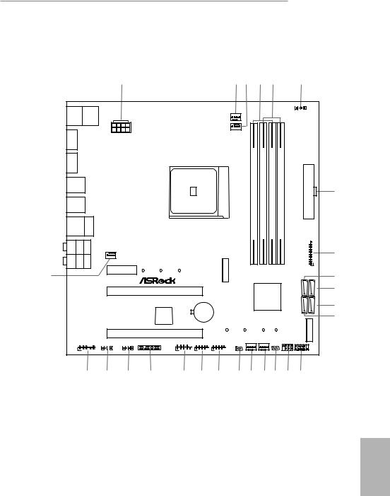
B450M Steel Legend
Motherboard Layout
|
1 |
2 |
3 |
4 |
5 |
6 |
|||||||||||||||
|
Keyboard/ Mouse |
1 |
|||||||||||||||||||
|
AMD_FAN_LED1 |
||||||||||||||||||||
|
PS2 |
USB 2.0 |
|||||||||||||||||||
|
T: USB1 |
||||||||||||||||||||
|
B: USB2 |
||||||||||||||||||||
|
CPU_FAN2/WP |
||||||||||||||||||||
|
CPU_FAN1 |
||||||||||||||||||||
|
DP1 |
ATX12V1 |
|||||||||||||||||||
|
HDMI1 |
AM4 SOCKET |
DDR4 A1(64bit,288-pinmodule) |
DDR4 A2(64bit,288-pinmodule) |
DDR4 B1(64bit,288-pinmodule) |
DDR4 B2(64bit,288-pinmodule) |
|||||||||||||||
|
USB 3.1 Gen1 |
STEELLEGEND |
ATXPWR1 |
||||||||||||||||||
|
T: USB3_3 |
||||||||||||||||||||
|
B: USB3_4 |
7 |
|||||||||||||||||||
|
USB 3.1 Gen1 |
B450M |
|||||||||||||||||||
|
T: USB3_1 |
||||||||||||||||||||
|
B: USB3_2 |
||||||||||||||||||||
|
USB 3.1 Gen2 |
RJ-45 LA |
|||||||||||||||||||
|
T: USB31_TA_1 |
||||||||||||||||||||
|
B: USB31_TC_1 |
||||||||||||||||||||
|
N |
||||||||||||||||||||
|
SPDIF Optical Bottom: |
REARSPK |
Center: |
Central/Bas Top: s |
CHA_FAN1/WP |
56 |
8 |
||||||||||||||
|
USB3 |
||||||||||||||||||||
|
MI Bottom: CI N |
FRONT |
Center: |
LINE Top: IN |
1 |
||||||||||||||||
|
1 |
||||||||||||||||||||
|
PCIE1 |
_ |
|||||||||||||||||||
|
M2 |
||||||||||||||||||||
|
26 |
M2_1_CT1 |
M2_1_CT2 |
M2_1_CT3 |
9 |
||||||||||||||||
|
SATA3 3 |
10 |
|||||||||||||||||||
|
PCIE2 |
AMD |
SATA34 |
||||||||||||||||||
|
RoHS |
Promontory |
|||||||||||||||||||
|
B450 |
SATA3 1 |
|||||||||||||||||||
|
11 |
||||||||||||||||||||
|
CMOS |
SATA32 |
|||||||||||||||||||
|
USB 3.1 Gen2 |
||||||||||||||||||||
|
Super |
Battery |
|||||||||||||||||||
|
12 |
||||||||||||||||||||
|
Ultra M.2 |
I/O |
|||||||||||||||||||
|
PCIe Gen3 x4 |
||||||||||||||||||||
|
PCIE3 |
M2_2_CT4 |
M2_2_CT3 |
M2_2_CT2 |
M2_2_CT1 |
M2 2 |
|||||||||||||||
|
HD_AUDIO1 |
COM1 |
CHA_FAN3/WP CHA_FAN2/WP |
SPK_PLED1 |
PANEL1 |
||||||||||||||||
|
TPMS1 |
USB_3_4 |
USB_5_6 |
PLED PWRBTN |
|||||||||||||||||
|
ADDR_LED1 |
RGB_HEADER1 |
CLRCMOS1 |
CI1 |
|||||||||||||||||
|
1 |
1 |
1 |
1 |
|||||||||||||||||
|
1 |
1 |
1 |
1 |
1 |
1 |
1 |
||||||||||||||
|
HDLED RESET |
||||||||||||||||||||
|
25 |
24 |
23 |
22 |
21 |
20 |
19 |
18 |
17 |
16 |
15 |
14 |
13 |
English
1

No. Description
1ATX 12V Power Connector (ATX12V1)
2CPU/Water Pump Fan Connector (CPU_FAN2/WP)
3CPU Fan Connector (CPU_FAN1)
42 x 288-pin DDR4 DIMM Slots (DDR4_A1, DDR4_B1)
52 x 288-pin DDR4 DIMM Slots (DDR4_A2, DDR4_B2)
6AMD Fan LED Header (AMD_FAN_LED1)
7ATX Power Connector (ATXPWR1)
8USB 3.1 Gen1 Header (USB3_56)
9SATA3 Connector (SATA3_3)
10SATA3 Connector (SATA3_4)
11SATA3 Connector (SATA3_2)
12SATA3 Connector (SATA3_1)
13System Panel Header (PANEL1)
14Power LED and Speaker Header (SPK_PLED1)
15Chassis Intrusion Header (CI1)
16Chassis/Water Pump Fan Connector (CHA_FAN2/WP)
17Chassis/Water Pump Fan Connector (CHA_FAN3/WP)
18Clear CMOS Jumper (CLRCMOS1)
19USB 2.0 Header (USB_5_6)
20USB 2.0 Header (USB_3_4)
21COM Port Header (COM1)
22TPM Header (TPMS1)
23RGB LED Header (RGB_HEADER1)
24Addressable LED Header (ADDR_LED1)
25Front Panel Audio Header (HD_AUDIO1)
26Chassis/Water Pump Fan Connector (CHA_FAN1/WP)
English
2
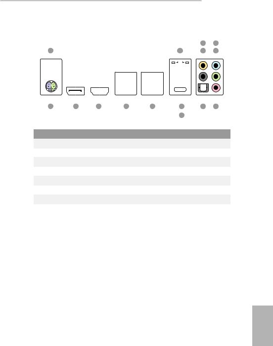
B450M Steel Legend
I/O Panel
|
3 |
5 |
|||||||||||||||||||||||||||||
|
1 |
2 |
4 |
6 |
|||||||||||||||||||||||||||
|
15 |
14 |
13 |
12 |
11 |
9 |
8 |
7 |
|
|
10 |
||||||||
|
No. |
Description |
No. |
Description |
|||||
|
1 |
USB 2.0 Ports (USB_1_2)* |
9 |
USB 3.1 Gen2 Type-A Port (USB31_TA_1) |
|||||
|
2 |
LAN RJ-45 Port** |
10 |
USB 3.1 Gen2 Type-C Port (USB31_TC_1) |
|||||
|
3 |
Central / Bass (Orange) |
11 |
USB 3.1 Gen1 Ports (USB3_12) |
|||||
|
4 |
Rear Speaker (Black) |
12 |
USB 3.1 Gen1 Ports (USB3_34) |
|||||
|
5 |
Line In (Light Blue) |
13 |
HDMI Port |
|||||
|
6 |
Front Speaker (Lime)*** |
14 |
DisplayPort 1.2 |
|||||
|
7 |
Microphone (Pink) |
15 |
PS/2 Mouse/Keyboard Port |
|||||
|
8 |
Optical SPDIF Out Port |
|||||||
English
3
*Please note that the USB_1 and USB_2 consume auxiliary power (+5VSB) while the other USB ports consume DUAL Power (+5VDUAL). The USB_1 and USB_2 are optimal for connecting the USB Type speaker and headset.
**There are two LEDs on each LAN port. Please refer to the table below for the LAN port LED indications.
ACT/LINK LED
|
SPEED LED |
|||||||||||
|
LAN Port |
|||||||||||
|
Activity / Link LED |
Speed LED |
||||||||||
|
Status |
Description |
Status |
Description |
||||||||
|
Off |
No Link |
Off |
10Mbps connection |
||||||||
|
Blinking |
Data Activity |
Orange |
100Mbps connection |
||||||||
|
On |
Link |
Green |
1Gbps connection |
||||||||
*** If you use a 2-channel speaker, please connect the speaker’s plug into “Front Speaker Jack”. See the table below for connection details in accordance with the type of speaker you use.
|
Audio Output |
Front Speaker |
Rear Speaker |
Central / Bass |
Line In |
|
Channels |
(No. 6) |
(No. 4) |
(No. 3) |
(No. 5) |
|
2 |
V |
— |
— |
— |
|
4 |
V |
V |
— |
— |
|
6 |
V |
V |
V |
— |
|
8 |
V |
V |
V |
V |
English
4
B450M Steel Legend
Chapter 1 Introduction
Thank you for purchasing ASRock B450M Steel Legend motherboard, a reliable motherboard produced under ASRock’s consistently stringent quality control. It delivers excellent performance with robust design conforming to ASRock’s commitment to quality and endurance.
Because the motherboard specifications and the BIOS software might be updated, the content of this manual will be subject to change without notice. In case any modifications of this manual occur, the updated version will be available on ASRock’s website without further notice. If you require technical support related to this motherboard, please visit our website for specific information about the model you are using. You may find the latest VGA cards and CPU support list on ASRock’s website as well. ASRock website http://www.asrock.com.
1.1 Package Contents
•ASRock B450M Steel Legend Motherboard (Micro ATX Form Factor)
•ASRock B450M Steel Legend Quick Installation Guide
•ASRock B450M Steel Legend Support CD
•1 x I/O Panel Shield
•2 x Serial ATA (SATA) Data Cables (Optional)
•2 x Screws for M.2 Sockets (Optional)
English
5

English
1.2 Specifications
|
Platform |
• |
Micro ATX Form Factor |
|
CPU |
• |
AMD AM4 Socket |
|
• |
Digi Power design |
|
|
• 6 Power Phase design |
||
|
• Supports 105W Water Cooling (Pinnacle Ridge); Supports |
||
|
95W Water Cooling (Summit Ridge); Supports 65W Water |
||
|
Cooling (Raven Ridge) |
||
|
Chipset |
• |
AMD Promontory B450 |
|
Memory |
• |
Dual Channel DDR4 Memory Technology |
•4 x DDR4 DIMM Slots
•AMD Ryzen series CPUs (Pinnacle Ridge) support DDR4 3533+(OC)/3200(OC)/2933(OC)/2667/2400/2133 ECC & nonECC, un-buffered memory*
•AMD Ryzen series CPUs (Summit Ridge) support DDR4 3466+(OC)/3200(OC)/2933(OC)/2667/2400/2133 ECC & non-ECC, un-buffered memory*
•AMD Ryzen series CPUs (Raven Ridge) support DDR4 3466+(OC)/3200(OC)/2933/2667/2400/2133 non-ECC, unbuffered memory*
*For Ryzen Series CPUs (Raven Ridge), ECC is only supported with PRO CPUs.
*Please refer to Memory Support List on ASRock’s website for more information. (http://www.asrock.com/)
*Please refer to page 22 for the table for AMD non-XMP memory frequency support. For more details, please refer to the QVL on ASRock’s website.
•Max. capacity of system memory: 64GB
•15μ Gold Contact in DIMM Slots
|
Expansion |
AMD Ryzen series CPUs (Summit Ridge and Pinnacle Ridge) |
|
Slot |
• 1 x PCI Express 3.0 x16 Slot (PCIE2: x16 mode)* |
|
• 1 x PCI Express 2.0 x16 Slot (PCIE3: x4 mode) |
|
|
AMD Ryzen series CPUs (Raven Ridge) |
|
|
• 1 x PCI Express 3.0 x16 Slot (PCIE2: x8 mode)* |
|
|
• 1 x PCI Express 2.0 x16 Slot (PCIE3: x4 mode) |
6

B450M Steel Legend
AMD Athlon series CPUs
|
• 1 x PCI Express 3.0 x16 Slot (PCIE2: x4 mode)* |
|
|
• 1 x PCI Express 2.0 x16 Slot (PCIE3: x4 mode) |
|
|
* Supports NVMe SSD as boot disks |
|
|
• 1 x PCI Express 2.0 x1 Slot |
|
|
• Supports AMD Quad CrossFireXTM and CrossFireXTM |
|
|
Graphics |
• Integrated AMD RadeonTM Vega Series Graphics in Ryzen |
|
Series APU* |
|
|
* Actual support may vary by CPU |
|
|
• DirectX 12, Pixel Shader 5.0 |
|
|
• Shared memory default 2GB. Max Shared memory supports |
|
|
up to 16GB. |
|
|
* The Max shared memory 16GB requires 32GB system memory |
|
|
installed. |
|
|
• Dual graphics output: Support HDMI and DisplayPort 1.2 |
|
|
ports by independent display controllers |
|
|
• Supports HDMI 1.4 with max. resolution up to 4K x 2K |
|
|
(4096×2160) @ 24Hz / (3840×2160) @ 30Hz |
|
|
• Supports DisplayPort 1.2 with max. resolution up to 4K x 2K |
|
|
(4096×2160) @ 60Hz |
|
|
• Supports Auto Lip Sync, Deep Color (12bpc), xvYCC and |
|
|
HBR (High Bit Rate Audio) with HDMI 1.4 Port (Compliant |
|
|
HDMI monitor is required) |
|
|
• Supports HDCP 1.4 with HDMI 1.4 and DisplayPort 1.2 Ports |
|
|
• Supports 4K Ultra HD (UHD) playback with HDMI 1.4 and |
|
|
DisplayPort 1.2 Ports |
|
|
Audio |
• 7.1 CH HD Audio with Content Protection (Realtek ALC892 |
|
Audio Codec) |
|
|
• Premium Blu-ray Audio support |
|
|
• Supports Surge Protection |
|
|
• Nichicon Fine Gold Series Audio Caps |
|
|
• PCB Isolate Shielding |
|
|
• Individual PCB Layers for R/L Audio Channel |
|
|
• Gold Audio Jacks |
English
7

|
LAN |
• |
PCIE x1 Gigabit LAN 10/100/1000 Mb/s |
|
• |
Realtek RTL8111H |
|
|
• Supports Wake-On-LAN |
||
|
• |
Supports Lightning/ESD Protection |
|
|
• Supports Energy Efficient Ethernet 802.3az |
||
|
• |
Supports PXE |
|
|
Rear Panel |
• |
1 x PS/2 Mouse/Keyboard Port |
|
I/O |
• |
1 x HDMI Port |
|
• 1 x DisplayPort 1.2 |
||
|
• 1 x Optical SPDIF Out Port |
||
|
• 2 x USB 2.0 Ports (Supports ESD Protection) |
||
|
• 1 x USB 3.1 Gen2 Type-A Port (10 Gb/s) (Supports ESD Pro- |
||
|
tection) |
||
|
• 1 x USB 3.1 Gen2 Type-C Port (10 Gb/s) (Supports ESD Pro- |
||
|
tection) |
||
|
• 4 x USB 3.1 Gen1 Ports (Supports ESD Protection) |
||
|
• 1 x RJ-45 LAN Port with LED (ACT/LINK LED and SPEED |
||
|
LED) |
||
|
• HD Audio Jacks: Rear Speaker / Central / Bass / Line in / |
||
|
Front Speaker / Microphone (Gold Audio Jacks) |
||
|
Storage |
• |
4 x SATA3 6.0 Gb/s Connectors, support RAID (RAID 0, |
|
RAID 1 and RAID 10), NCQ, AHCI and Hot Plug* |
||
|
* M2_2 and SATA3_3 share lanes. If either one of them is in use, |
||
|
the other one will be disabled. |
• 1 x Ultra M.2 Socket (M2_1), supports M Key type 2242/2260/2280 M.2 PCI Express module up to Gen3 x4 (32 Gb/s) (with Summit Ridge, Raven Ridge and Pinnacle Ridge) or Gen3 x2 (16 Gb/s) (with Athlon 2xxGE series APU)**
• 1 x M.2 Socket (M2_2), supports M Key type 2230/2242/2260/2280 M.2 SATA3 6.0 Gb/s module**
** Supports NVMe SSD as boot disks ** Supports ASRock U.2 Kit
English
8
![]()
B450M Steel Legend
Connector • 1 x COM Port Header
•1 x TPM Header
•1 x Chassis Intrusion Header
•1 x Power LED and Speaker Header
•1 x RGB LED Header
*Supports in total up to 12V/3A, 36W LED Strip
•1 x Addressable LED Header
*Supports in total up to 5V/3A, 15W LED Strip
•1 x AMD Fan LED Header
*The AMD Fan LED Header supports LED strips of maximum load of 3A (36W) and length up to 2.5M.
•1 x CPU Fan Connector (4-pin)
*The CPU Fan Connector supports the CPU fan of maximum 1A (12W) fan power.
•1 x CPU/Water Pump Fan Connector (4-pin) (Smart Fan Speed Control)
*The CPU/Water Pump Fan supports the water cooler fan of maximum 2A (24W) fan power.
•3 x Chassis/Water Pump Fan Connectors (4-pin) (Smart Fan Speed Control)
*The Chassis/Water Pump Fan supports the water cooler fan of maximum 2A (24W) fan power.
*CPU_FAN2/WP, CHA_FAN1/WP, CHA_FAN2/WP and CHA_FAN3/WP can auto detect if 3-pin or 4-pin fan is in use.
•1 x 24 pin ATX Power Connector
•1 x 8 pin 12V Power Connector
•1 x Front Panel Audio Connector
•2 x USB 2.0 Headers (Support 4 USB 2.0 ports) (Supports ESD Protection)
•1 x USB 3.1 Gen1 Header (Supports 2 USB 3.1 Gen1 ports) (Supports ESD Protection)
|
BIOS |
• |
AMI UEFI Legal BIOS with multilingual GUI support |
|
Feature |
• |
Supports “Plug and Play” |
|
• ACPI 5.1 compliance wake up events |
||
|
• |
Supports jumperfree |
|
|
• |
SMBIOS 2.3 support |
• DRAM Voltage multi-adjustment
English
9
|
Hardware |
• |
Temperature Sensing: CPU, CPU/Water Pump, Chassis/Wa- |
|
Monitor |
ter Pump Fans |
|
|
• Fan Tachometer: CPU, CPU/Water Pump, Chassis/Water |
||
|
Pump Fans |
||
|
• Quiet Fan (Auto adjust chassis fan speed by CPU tempera- |
||
|
ture): CPU, CPU/Water Pump, Chassis/Water Pump Fans |
||
|
• Fan Multi-Speed Control: CPU, CPU/Water Pump, Chassis/ |
||
|
Water Pump Fans |
||
|
• |
CASE OPEN detection |
|
|
• Voltage monitoring: +12V, +5V, +3.3V, Vcore |
||
|
OS |
• |
Microsoft® Windows® 10 64-bit |
|
Certifica- |
• |
FCC, CE |
|
tions |
• |
ErP/EuP ready (ErP/EuP ready power supply is required) |
* For detailed product information, please visit our website: http://www.asrock.com
Please realize that there is a certain risk involved with overclocking, including adjusting the setting in the BIOS, applying Untied Overclocking Technology, or using thirdparty overclocking tools. Overclocking may affect your system’s stability, or even cause damage to the components and devices of your system. It should be done at your own risk and expense. We are not responsible for possible damage caused by overclocking.
English
10

B450M Steel Legend
Chapter 2 Installation
This is a Micro ATX form factor motherboard. Before you install the motherboard, study the configuration of your chassis to ensure that the motherboard fits into it.
Pre-installation Precautions
Take note of the following precautions before you install motherboard components or change any motherboard settings.
•Make sure to unplug the power cord before installing or removing the motherboard. Failure to do so may cause physical injuries to you and damages to motherboard components.
•In order to avoid damage from static electricity to the motherboard’s components, NEVER place your motherboard directly on a carpet. Also remember to use a grounded wrist strap or touch a safety grounded object before you handle the components.
•Hold components by the edges and do not touch the ICs.
•Whenever you uninstall any components, place them on a grounded anti-static pad or in the bag that comes with the components.
•When placing screws to secure the motherboard to the chassis, please do not overtighten the screws! Doing so may damage the motherboard.
English
11
2.1 Installing the CPU
Unplug all power cables before installing the CPU.
1
2
English
12
B450M Steel Legend
3
English
13
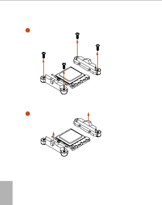
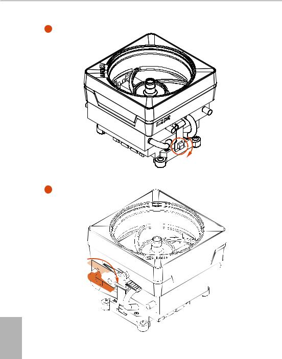
2.2 Installing the CPU Fan and Heatsink
After you install the CPU into this motherboard, it is necessary to install a larger heatsink and cooling fan to dissipate heat. You also need to spray thermal grease between the CPU and the heatsink to improve heat dissipation. Make sure that the CPU and the heatsink are securely fastened and in good contact with each other.
Please turn off the power or remove the power cord before changing a CPU or heatsink.
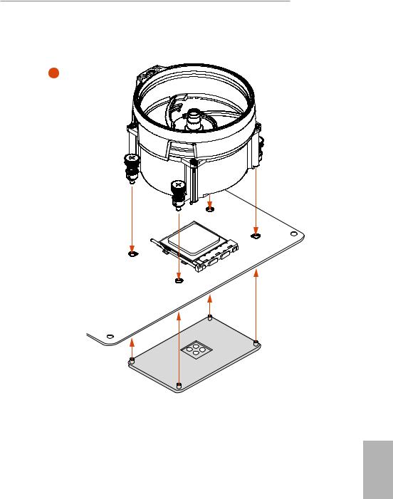
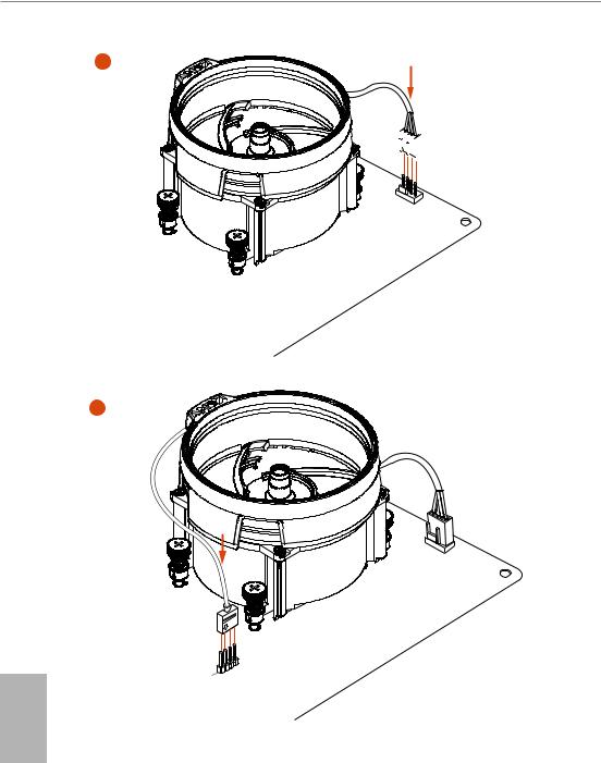
Installing the CPU Box Cooler SR1
1
2
English
14
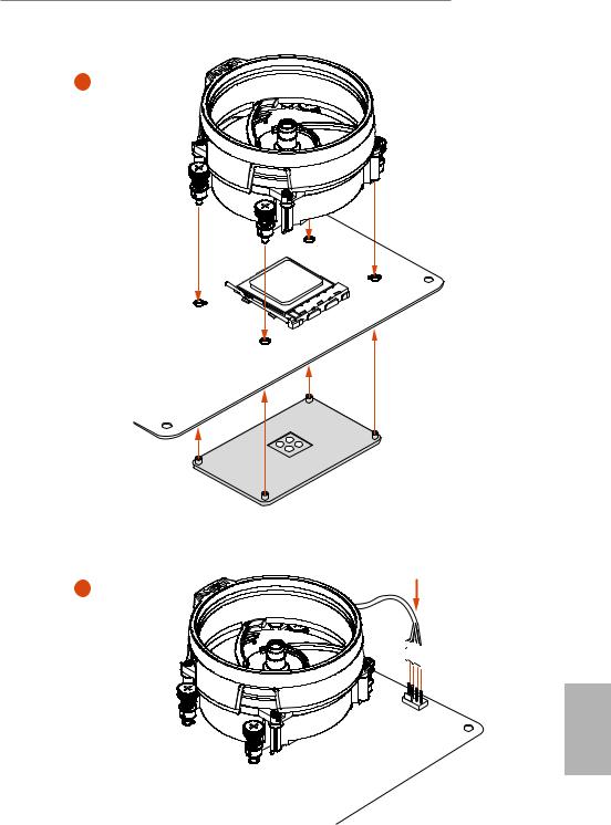
15
Installing the AM4 Box Cooler SR2
1
2
English
16
B450M Steel Legend
3
English
17
4


 4-pin FAN cable
5
4-pin FAN cable
RGB LED Cable
English
|
1 |
||
|
ED |
||
|
L |
||
|
_ |
||
|
+12V |
N |
|
|
AM |
||
|
_FA |
||
|
D |
*The diagram shown here are for reference only. Please refer to page 31 for the orientation of AMD Fan LED Header (AMD_FAN_LED1).
18
![]()
B450M Steel Legend
Installing the AM4 Box Cooler SR3
1
2
English
19
20

B450M Steel Legend
5
 4-pin FAN cable
6
_FAN1 PU C
USB 2.0 Header
Please note that this connector is the interface to the LED control board on the SR3, it requires the AMD utility «SR3 Settings Software» to control the LED.
*The diagram shown here are for reference only. Please refer to page 28 for the orientation of USB Header.
English
21
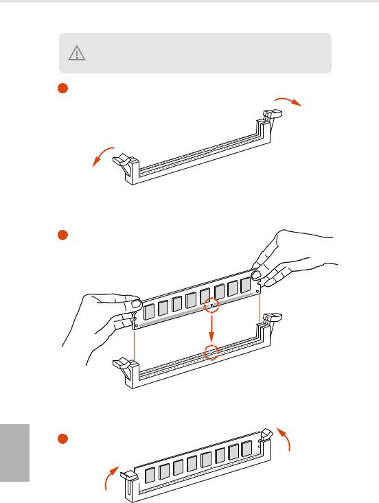
2.3 Installing Memory Modules (DIMM)
This motherboard provides four 288-pin DDR4 (Double Data Rate 4) DIMM slots, and supports Dual Channel Memory Technology.
1.For dual channel configuration, you always need to install identical (the same brand, speed, size and chip-type) DDR4 DIMM pairs.
2.It is unable to activate Dual Channel Memory Technology with only one or three memory module installed.
3.It is not allowed to install a DDR, DDR2 or DDR3 memory module into a DDR4 slot; otherwise, this motherboard and DIMM may be damaged.
4.We suggest that you install the memory modules on DDR4_A2 and DDR4_B2 for Dual Channel Memory Technology.
AMD non-XMP Memory Frequency Support
Ryzen Series CPUs (Pinnacle Ridge):
|
UDIMM Memory Slot |
Frequency |
|||
|
A1 |
A2 |
B1 |
B2 |
(Mhz) |
|
— |
SR |
— |
— |
2933 |
|
— |
DR |
— |
— |
2933 |
|
— |
SR |
— |
SR |
2933 |
|
— |
DR |
— |
DR |
2933 |
|
SR |
SR |
SR |
SR |
2933 |
|
SR/DR |
DR |
SR/DR |
DR |
2667 |
|
SR/DR |
SR/DR |
SR/DR |
SR/DR |
2133-2400 |
English
22

B450M Steel Legend
Ryzen Series CPUs (Summit Ridge):
|
UDIMM Memory Slot |
Frequency |
|||
|
A1 |
A2 |
B1 |
B2 |
(Mhz) |
|
— |
SR |
— |
— |
2667 |
|
— |
DR |
— |
— |
2667 |
|
— |
SR |
— |
SR |
2667 |
|
— |
DR |
— |
DR |
2667 |
|
SR |
SR |
SR |
SR |
2667 |
|
SR/DR |
DR |
SR/DR |
DR |
2667 |
|
SR/DR |
SR/DR |
SR/DR |
SR/DR |
2133-2400 |
Ryzen Series CPUs (Raven Ridge):
|
UDIMM Memory Slot |
Frequency |
|||
|
A1 |
A2 |
B1 |
B2 |
(Mhz) |
|
— |
SR |
— |
— |
2933 |
|
— |
DR |
— |
— |
2667 |
|
— |
SR |
— |
SR |
2667 |
|
— |
DR |
— |
DR |
2667 |
|
SR |
SR |
SR |
SR |
2667 |
|
SR/DR |
DR |
SR/DR |
DR |
2667 |
|
SR/DR |
SR/DR |
SR/DR |
SR/DR |
2133-2400 |
SR: Single rank DIMM, 1Rx4 or 1Rx8 on DIMM module label
DR: Dual rank DIMM, 2Rx4 or 2Rx8 on DIMM module label
English
23
English
The DIMM only fits in one correct orientation. It will cause permanent damage to the motherboard and the DIMM if you force the DIMM into the slot at incorrect orientation.
1
2
3
24
B450M Steel Legend
2.4 Expansion Slots (PCI Express Slots)
There are 3 PCI Express slots on the motherboard.
Before installing an expansion card, please make sure that the power supply is switched off or the power cord is unplugged. Please read the documentation of the expansion card and make necessary hardware settings for the card before you start the installation.
PCIe slots:
PCIE1 (PCIe 2.0 x1 slot) is used for PCI Express x1 lane width cards.
PCIE2 (PCIe 3.0 x16 slot) is used for PCI Express x16 lane width graphics cards. PCIE3 (PCIe 2.0 x16 slot) is used for PCI Express x4 lane width graphics cards.
PCIe Slot Configurations
|
PCIE1 |
PCIE2 |
PCIE3 |
|
|
Ryzen Series CPUs (Pinnacle Ridge) |
x1 |
x16 |
x4 |
|
Ryzen Series CPUs (Summit Ridge) |
x1 |
x16 |
x4 |
|
Ryzen Series CPUs (Raven Ridge) |
x1 |
x8 |
x4 |
|
Athlon series CPUs |
x1 |
x4 |
x4 |
For a better thermal environment, please connect a chassis fan to the motherboard’s chassis fan connector (CHA_FAN1/WP, CHA_FAN2/WP or CHA_FAN3/WP) when using multiple graphics cards.
English
25
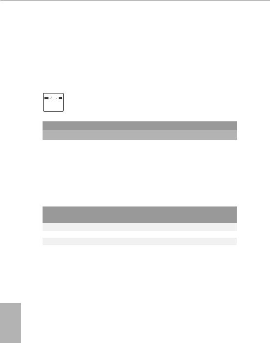
2.5 Jumpers Setup
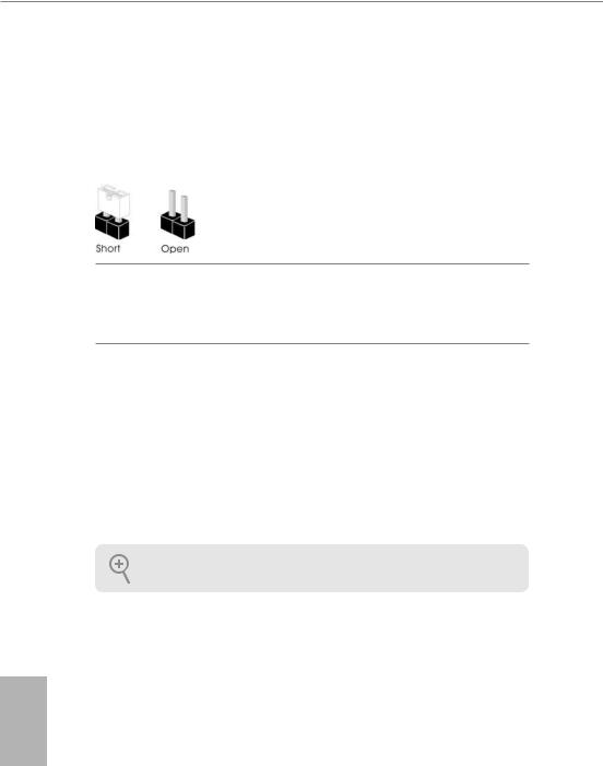
The illustration shows how jumpers are setup. When the jumper cap is placed on the pins, the jumper is “Short”. If no jumper cap is placed on the pins, the jumper is “Open”.
|
Clear CMOS Jumper |
Short: Clear CMOS |
|
|
(CLRCMOS1) |
2-pin Jumper |
Open: Default |
|
(see p.1, No. 18) |
||
CLRCMOS1 allows you to clear the data in CMOS. To clear and reset the system parameters to default setup, please turn off the computer and unplug the power cord from the power supply. After waiting for 15 seconds, use a jumper cap to short the pins on CLRCMOS1 for 5 seconds. However, please do not clear the CMOS right after you update the BIOS. If you need to clear the CMOS when you just finish updating the BIOS, you must boot up the system first, and then shut it down before you do the clear-CMOS action. Please be noted that the password, date, time, and user default profile will be cleared only if the CMOS battery is removed. Please remember toremove the jumper cap after clearing the CMOS.
If you clear the CMOS, the case open may be detected. Please adjust the BIOS option “Clear Status” to clear the record of previous chassis intrusion status.
English
26
B450M Steel Legend
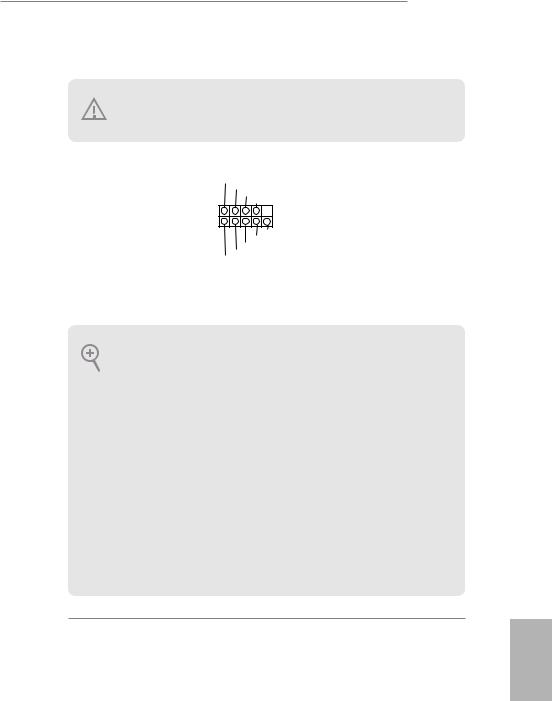
2.6 Onboard Headers and Connectors
Onboard headers and connectors are NOT jumpers. Do NOT place jumper caps over these headers and connectors. Placing jumper caps over the headers and connectors will cause permanent damage to the motherboard.
System Panel Header
(9-pin PANEL1)
(see p.1, No. 13)
PLED+ PLED-
PWRBTN#
GND
1
GND RESET#
GND HDLED-
HDLED+
Connect the power switch, reset switch and system status indicator on the chassis to this header according to the pin assignments below. Note the positive and negative pins before connecting the cables.
PWRBTN (Power Switch):
Connect to the power switch on the chassis front panel. You may configure the way to turn off your system using the power switch.
RESET (Reset Switch):
Connect to the reset switch on the chassis front panel. Press the reset switch to restart the computer if the computer freezes and fails to perform a normal restart.
PLED (System Power LED):
Connect to the power status indicator on the chassis front panel. The LED is on when the system is operating. The LED keeps blinking when the system is in S3 sleep state. The LED is off when the system is in S4 sleep state or powered off (S5).
HDLED (Hard Drive Activity LED):
Connect to the hard drive activity LED on the chassis front panel. The LED is on when the hard drive is reading or writing data.
The front panel design may differ by chassis. A front panel module mainly consists of power switch, reset switch, power LED, hard drive activity LED, speaker and etc. When connecting your chassis front panel module to this header, make sure the wire assignments and the pin assignments are matched correctly.
English
27
English
Power LED and Speaker
Header
(7-pin SPK_PLED1)
(see p.1, No. 14)
SPEAKER
DUMMY DUMMY +5V
1 
PLED+
PLED+ PLED-
Please connect the chassis power LED and the chassis speaker to this header.
|
Serial ATA3 Connectors |
3 |
4 |
These four SATA3 |
|
see p.1, No. 12) |
SATA3 |
SATA3 |
data cables for internal |
|
(SATA3_1: |
connectors support SATA |
||
|
(SATA3_2: |
1 |
2 |
storage devices with up to |
|
see p.1, No. 11) |
SATA3 |
SATA3 |
6.0 Gb/s data transfer rate. |
|
(SATA3_3: |
* M2_2 and SATA3_3 |
||
|
see p.1, No. 9) |
share lanes. If either one |
||
|
(SATA3_4: |
of them is in use, the other |
||
|
see p.1, No. 10) |
one will be disabled. |
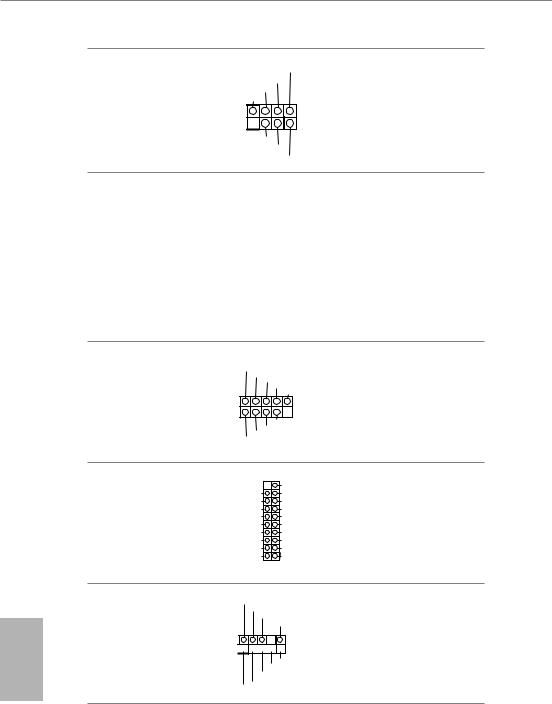
USB 2.0 Headers
(9-pin USB_3_4)
(see p.1, No. 20)
(9-pin USB_5_6)
(see p.1, No. 19)
USB_PWR
P- P+ GND DUMMY
1
GND
USBP_—PWRP+
There are two headers on this motherboard. Each USB 2.0 header can support two ports.
USB 3.1 Gen1 Header (19-pin USB3_56) (see p.1 or 8, No. 
Vbus
IntA_PA_SSRX-
IntA_PA_SSRX+
GND
IntA_PA_SSTX-
IntA_PA_SSTX+
GND
IntA_PA_D-
IntA_PA_D+
Vbus
IntA_PB_SSRX-
IntA_PB_SSRX+
GND
IntA_PB_SSTX-
IntA_PB_SSTX+
GND
IntA_PB_D-
IntA_PB_D+
Dummy
1
There is one header on this motherboard. Each USB 3.1 Gen1 header can support two ports.
Front Panel Audio Header
(9-pin HD_AUDIO1)
(see p.1, No. 25)
GND PRESENCE#
MIC_RET
OUT_RET
1


OUT2_L J_SENSE
OUT2_R MIC2_R
MIC2_L
This header is for connecting audio devices to the front audio panel.
28
![]()
B450M Steel Legend
1.High Definition Audio supports Jack Sensing, but the panel wire on the chassis must support HDA to function correctly. Please follow the instructions in our manual and chassis manual to install your system.
2.If you use an AC’97 audio panel, please install it to the front panel audio header by the steps below:
A.Connect Mic_IN (MIC) to MIC2_L.
B.Connect Audio_R (RIN) to OUT2_R and Audio_L (LIN) to OUT2_L.
C.Connect Ground (GND) to Ground (GND).
D.MIC_RET and OUT_RET are for the HD audio panel only. You don’t need to connect them for the AC’97 audio panel.
E.To activate the front mic, go to the “FrontMic” Tab in the Realtek Control panel and adjust “Recording Volume”.
Chassis/Water Pump Fan
Connectors
(4-pin CHA_FAN1/WP)
(see p.1, No. 26)
(4-pin CHA_FAN2/WP)
(see p.1, No. 16)
4 3 2 1
GND +12V
FAN_SPEED FAN_SPEED_CONTROL
|
FAN_SPEED_CONTROL |
4 |
|
FAN_SPEED |
3 |
|
FAN_VOLTAGE |
2 |
|
GND |
1 |
This motherboard provides three 4-Pin water cooling chassis fan connectors. If you plan to connect a 3-Pin chassis water cooler fan, please connect it to Pin 1-3.
|
FAN_SPEED |
||
|
(4-pin CHA_FAN3/WP) |
FAN_VOLTAGE_CONTROL |
|
|
GND |
FAN_SPEED_CONTROL |
|
|
(see p.1, No. 17) |
||
CPU Fan Connector
(4-pin CPU_FAN1)
(see p.1, No. 3)
FAN_SPEED
FAN_VOLTAGE_CONTROL
GND FAN_SPEED_CONTROL
This motherboard provides a 4-Pin CPU fan (Quiet Fan) connector. If you plan to connect a 3-Pin CPU fan, please connect it to Pin 1-3.
CPU/Water Pump Fan
Connector
(4-pin CPU_FAN2/WP)
(see p.1, No. 2)
FAN_SPEED
FAN_VOLTAGE_CONTROL
GND FAN_SPEED_CONTROL
This motherboard provides a 4-Pin water cooling CPU fan connector. If you plan to connect a 3-Pin CPU water cooler fan, please connect it to Pin 1-3.
English
29

English
|
ATX Power Connector |
12 |
24 |
This motherboard pro- |
|
(24-pin ATXPWR1) |
vides a 24-pin ATX power |
||
|
(see p.1, No. 7) |
connector. To use a 20-pin |
||
|
ATX power supply, please |
|||
|
plug it along Pin 1 and Pin |
|||
|
1 |
13 |
13. |
ATX 12V Power
Connector
(8-pin ATX12V1)
(see p.1, No. 1)
This motherboard provides a 8-pin ATX 12V power connector. To use a 4-pin ATX power supply, please plug it along Pin 1 and Pin 5.
|
Serial Port Header |
DDTR#1 |
This COM1 header |
|
(9-pin COM1) |
RRXD1 |
supports a serial port |
|
CCTS#1 |
||
|
DDSR#1 |
||
|
(see p.1, No. 21) |
module. |
1
RRI#1
RRTS#1 GND
TTXD1
DDCD#1
|
Chassis Intrusion Header |
1 |
|||||
|
(2-pin CI1) |
GND |
|||||
|
(see p.1, No. 15) |
Signal |
|||||
This motherboard supports CASE OPEN detection feature that detects if the chassis cove has been removed. This feature requires a chassis with chassis intrusion detection design.
TPM Header
(17-pin TPMS1)
(see p.1, No. 22)
|
GND |
+3VSB |
LAD0 |
+3V |
LAD3 |
PCIRST# |
FRAME |
PCICLK |
|
1 |
|||||||
|
GND |
SERIRQ# S_PWRDWN# |
GND |
LAD1 |
LAD2 |
SMB_DATA_MAIN |
SMB_CLK_MAIN |
DGN |
This connector supports Trusted Platform Module (TPM) system, which can securely store keys, digital certificates, passwords, and data. A TPM system also helps enhance network security, protects digital identities, and ensures platform integrity.
30

B450M Steel Legend
AMD FAN LED Header
(4-pin AMD_FAN_
LED1)
(see p.1, No. 6)
1 
12V G R B
AMD FAN LED Header is used to connect RGB LED extension cable that comes with AMD heatsink. The cable
connection allows users to choose from various LED lighting effects.
Caution: Never install the FAN LED cable in the wrong orientation; otherwise, the cable may be damaged.
RGB LED Header
(4-pin RGB_LED1)
(see p.1, No. 23)
1 
12V G R B
This header is used to connect RGB LED extension cable which allows users to choose from various LED lighting effects.
Caution: Never install the RGB LED cable in the wrong orientation; otherwise, the cable may be damaged.
*Please refer to page 38 for further instructions on this header.
|
Addressable LED Header |
1 |
||
|
(3-pin ADDR_LED1) |
|||
|
GND |
|||
|
(see p.1, No. 24) |
|||
|
DO_ADDR |
|||
|
VOUT |
This header is used to connect Addressable LED extension cable which allows users to choose from various LED lighting effects.
Caution: Never install the Addressable LED cable in the wrong orientation; otherwise, the cable may be damaged.
*Please refer to page 39 for further instructions on this header.
English
31

2.7 M.2_SSD (NGFF) Module Installation Guide (M2_1)
The M.2, also known as the Next Generation Form Factor (NGFF), is a small size and versatile card edge connector that aims to replace mPCIe and mSATA. The Ultra M.2 Socket (M2_1) supports M Key type 2242/2260/2280 M.2 PCI Express module up to Gen3 x4 (32 Gb/s) (with Summit Ridge, Raven Ridge and Pinnacle Ridge) or Gen3 x2 (16 Gb/s) (with Athlon 2xxGE series APU).
Installing the M.2_SSD (NGFF) Module
Step 1
Prepare a M.2_SSD (NGFF) module and the screw.
2
Depending on the PCB type and length of your M.2_SSD (NGFF) module, find the corresponding nut
location to be used.
1
C B A
|
No. |
1 |
2 |
3 |
|
Nut Location |
A |
B |
C |
|
PCB Length |
4.2cm |
6cm |
8cm |
|
Module Type |
Type 2242 |
Type2260 |
Type 2280 |
English
32

B450M Steel Legend
|
Step 3 |
||||
|
Move the standoff based on the |
||||
|
module type and length. |
||||
|
C |
B |
A |
The standoff is placed at the nut |
|
|
location C by default. Skip Step 3 |
||||
|
and 4 and go straight to Step 5 if you |
||||
|
are going to use the default nut. |
||||
|
Otherwise, release the standoff by |
||||
|
hand. |
|
Step 4 |
|||
|
Peel off the yellow protective film on |
|||
|
the nut to be used. Hand tighten the |
|||
|
C |
B |
A |
standoff into the desired nut location |
|
on the motherboard. |
Step 5
Gently insert the M.2 (NGFF) SSD module into the M.2 slot. Please be aware that the M.2 (NGFF) SSD module only fits in one orientation.
C B A
English
33

Step 6
Tighten the screw with a screwdriver to secure the module into place. Please do not overtighten the screw
|
C |
as this might damage the module. |
M.2_SSD (NGFF) Module Support List
|
Vendor |
Interface |
P/N |
|
SanDisk |
PCIe |
SanDisk-SD6PP4M-128G( Gen2 x2) |
|
Intel |
PCIe |
INTEL 6000P-SSDPEKKF256G7 (nvme) |
|
Intel |
PCIe |
INTEL 6000P-SSDPEKKF512G7 (nvme) |
|
Kingston |
PCIe |
Kingston SHPM2280P2 / 240G (Gen2 x4) |
|
Samsung |
PCIe |
Samsung XP941-MZHPU512HCGL(Gen2x4) |
|
ADATA |
SATA |
ADATA — AXNS381E-128GM-B |
|
Crucial |
SATA |
Crucial-CT240M500SSD4-240GB |
|
ezlink |
SATA |
ezlink P51B-80-120GB |
|
Intel |
SATA |
INTEL 540S-SSDSCKKW240H6-240GB |
|
Kingston |
SATA |
Kingston SM2280S3G2/120G — Win8.1 |
|
Kingston |
SATA |
Kingston-RBU-SNS8400S3 / 180GD |
|
LITEON |
SATA |
LITEON LJH-256V2G-256GB (2260) |
|
PLEXTOR |
SATA |
PLEXTOR PX-128M6G-2260-128GB |
|
PLEXTOR |
SATA |
PLEXTOR PX-128M7VG-128GB |
|
SanDisk |
SATA |
SanDisk X400-SD8SN8U-128G |
|
SanDisk |
SATA |
Sandisk Z400s-SD8SNAT-128G-1122 |
|
SanDisk |
SATA |
SanDisk-SD6SN1M-128G |
|
Transcend |
SATA |
Transcend TS256GMTS800-256GB |
|
V-Color |
SATA |
V-Color 120G |
|
V-Color |
SATA |
V-Color 240G |
|
WD |
SATA |
WD GREEN WDS240G1G0B-00RC30 |
For the latest updates of M.2_SSD (NFGG) module support list, please visit our website for details: http://www.asrock.com
English
34

B450M Steel Legend
2.8 M.2_SSD (NGFF) Module Installation Guide (M2_2)
The M.2, also known as the Next Generation Form Factor (NGFF), is a small size and versatile card edge connector that aims to replace mPCIe and mSATA. The M.2 Socket (M2_2) supports M Key type 2230/2242/2260/2280 M.2 SATA3 6.0 Gb/s module.
* M2_2 and SATA3_3 share lanes. If either one of them is in use, the other one will be disabled.
Installing the M.2_SSD (NGFF) Module
Step 1
Prepare a M.2_SSD (NGFF) module and the screw.
Step 2
Depending on the PCB type and length of your M.2_SSD (NGFF) module, find the corresponding nut location to be used.
3 4
|
Nut Location |
A |
B |
C |
D |
|
PCB Length |
3cm |
4.2cm |
6cm |
8cm |
|
Module Type |
Type2230 |
Type 2242 |
Type2260 |
Type 2280 |
English
35

English
|
Step 3 |
||||
|
Move the standoff based on the |
||||
|
module type and length. |
||||
|
D |
C |
B |
A |
The standoff is placed at the nut |
|
location D by default. Skip Step 3 and |
||||
|
4 and go straight to Step 5 if you are |
||||
|
going to use the default nut. |
||||
|
Otherwise, release the standoff by |
||||
|
hand. |
|
Step 4 |
||||
|
Peel off the yellow protective film on |
||||
|
D |
C |
B |
A |
the nut to be used. Hand tighten the |
|
standoff into the desired nut location |
||||
|
on the motherboard. |
Step 5
Gently insert the M.2 (NGFF) SSD module into the M.2 slot. Please be aware that the M.2 (NGFF) SSD module only fits in one orientation.
|
Step 6 |
|
|
Tighten the screw with a screwdriver |
|
|
to secure the module into place. |
|
|
D |
Please do not overtighten the screw as |
|
this might damage the module. |
36

B450M Steel Legend
M.2_SSD (NGFF) Module Support List
|
Vendor |
Interface |
P/N |
|
ADATA |
SATA |
ADATA — AXNS381E-128GM-B |
|
Crucial |
SATA |
Crucial-CT240M500SSD4-240GB |
|
EZLINK |
SATA |
EZLINK P51B-80-120GB |
|
Intel |
SATA |
INTEL 540S-SSDSCKKW240H6-240GB |
|
Kingston |
SATA |
Kingston-RBU-SNS8400S3 / 180GD |
|
Kingston |
SATA |
Kingston SM2280S3G2/120G — Win8.1 |
|
LITEON |
SATA |
LITEON LJH-256V2G-256GB (2260) |
|
PLEXTOR |
SATA |
PLEXTOR PX-128M7VG-128GB |
|
PLEXTOR |
SATA |
PLEXTOR PX-128M6G-2260-128GB |
|
SanDisk |
SATA |
SanDisk-SD6SN1M-128G |
|
SanDisk |
SATA |
SanDisk X400-SD8SN8U-128G |
|
SanDisk |
SATA |
Sandisk Z400s-SD8SNAT-128G-1122 |
|
Transcend |
SATA |
Transcend TS256GMTS800-256GB |
|
Transcend |
SATA |
Transcend TS64GMTS400-64GB |
|
V-Color |
SATA |
V-Color 120G |
|
V-Color |
SATA |
V-Color 240G |
|
WD |
SATA |
WD BLUE WDS100T1B0B-00AS40 |
|
WD |
SATA |
WD GREEN WDS240G1G0B-00RC30 |
For the latest updates of M.2_SSD (NFGG) module support list, please visit our website for details: http://www.asrock.com
English
37

2.9 ASRock Polychrome RGB
ASRock Polychrome RGB is a lighting control utility specifically designed for unique individuals with sophisticated tastes to build their own stylish colorful lighting system. Simply by connecting the LED strip, you can customize various lighting schemes and patterns, including Static, Breathing, Strobe, Cycling, Music, Wave and more.
Connecting the LED Strip
Connect your RGB LED strips to the RGB LED Header (RGB_HEADER1) on the motherboard.
 B450M Pro4
1
RGB_HEADER1
1 
12V G R B
1. Never install the RGB LED cable in the wrong orientation; otherwise, the cable may be damaged.
2.Before installing or removing your RGB LED cable, please power off your system and unplug the power cord from the power supply. Failure to do so may cause damages to motherboard components.
1.Please note that the RGB LED strips do not come with the package.
2.The RGB LED header supports standard 5050 RGB LED strip (12V/G/R/B), with a maximum power rating of 3A (12V) and length within 2 meters.
English
38
![]()
B450M Steel Legend
Connecting the Addressable RGB LED Strip
Connect your Addressable RGB LED strip to the Addressable LED Header (ADDR_LED1) on the motherboard.
 B450M Pro4
1

ADDR_LED1
1
GND
DO_ADDR
VOUT
1.Never install the RGB LED cable in the wrong orientation; otherwise, the cable may be damaged.
2.Before installing or removing your RGB LED cable, please power off your system and unplug the power cord from the power supply. Failure to do so may cause damages to motherboard components.
1.Please note that the RGB LED strips do not come with the package.
2.The RGB LED header supports WS2812B addressable RGB LED strip (5V/Data/ GND), with a maximum power rating of 3A (5V) and length within 2 meters.
English
39

ASRock Polychrome RGB Utility
Now you can adjust the RGB LED color through the ASRock Polychrome RGB utility. Download this utility from the ASRock Live Update & APP Shop and start coloring your PC style your way!
Toggle on/off the RGB LED switch
Sync RGB LED effects for all LED regions of the motherboard
Drag the tab to customize your preference.
Select a RGB LED light effect from the drop-down menu.
English
40

B450M Steel Legend
1 Einleitung
Vielen Dank, dass Sie sich für das B450M Steel Legend von ASRock entschieden haben – ein zuverlässiges Motherboard, das konsequent unter der strengen Qualitätskontrolle von ASRock hergestellt wurde. Es liefert ausgezeichnete Leistung mit robustem Design, das ASRock Streben nach Qualität und Beständigkeit erfüllt.
Da die technischen Daten des Motherboards sowie die BIOS-Software aktualisiert werden können, kann der Inhalt dieser Anleitung ohne Ankündigung geändert werden. Falls diese Anleitung irgendwelchen Änderungen unterliegt, wird die aktualisierte Version ohne weitere Hinweise
auf der ASRock-Webseite zur Verfügung gestellt. Sollten Sie technische Hilfe in Bezug auf dieses Motherboard benötigen, erhalten Sie auf unserer Webseite spezifischen Informationen über das von Ihnen verwendete Modell. Auch finden Sie eine aktuelle Liste unterstützter VGA-Karten und Prozessoren auf der ASRock-Webseite: ASRock-Webseite http://www.asrock.com.
1.1 Lieferumfang
•ASRock B450M Steel Legend-Motherboard (Micro-ATX-Formfaktor)
•ASRock B450M Steel Legend-Schnellinstallationsanleitung
•ASRock B450M Steel Legend-Support-CD
•1 x E/A-Blendenabschirmung
•2 x Serial-ATA- (SATA) Datenkabel (Optional)
•2 x Schrauben für M.2-Sockel (Optional)
Deutsch
41

Deutsch
1.2 Technische Daten
Plattform • Micro-ATX-Formfaktor
Prozessor • AMD-AM4-Sockel
•Digi Power design
•6-Leistungsphasendesign
•Unterstützt 105-W-Wasserkühlung (Pinnacle Ridge); unterstützt 95-W-Wasserkühlung (Summit Ridge); unterstützt 65-W-Wasserkühlung (Raven Ridge)
|
Chipsatz |
• AMD Promontory B450 |
Speicher • Dualkanal-DDR4-Speichertechnologie
•4 x DDR4-DIMM-Steckplätze
•Prozessoren der AMD-Ryzen-Serie (Pinnacle Ridge) unterstützen
DDR4 3533+(OC)/3200(OC)/2933(OC)/2667/2400/2133 ECC und non-ECC, ungepufferter Speicher*
•Prozessoren der AMD-Ryzen-Serie (Summit Ridge) unterstützen
DDR4 3466+(OC)/3200(OC)/2933(OC)/2667/2400/2133 ECC und non-ECC, ungepufferter Speicher*
•Prozessoren der AMD-Ryzen-Serie (Raven Ridge) unterstützen
DDR4 3466+(OC)/3200(OC)/2933/2667/2400/2133 non-ECC, ungepufferter Speicher*
*Für Prozessoren der Ryzen-Serie (Raven Ridge), ECC wird nur mit PRO-Prozessoren unterstützt.
*Weitere Informationen finden Sie in der Speicherkompatibilitätsliste auf der ASRock-Webseite. (http://www.asrock.com/)
*Die Tabelle für AMDs Non-XMP-Speicherfrequenzen finden Sie auf Seite 22. Weitere Einzelheiten finden Sie in der QVL auf ASRocks Webseite.
•Systemspeicher, max. Kapazität: 64GB
•15-μ-Goldkontakt in DIMM-Steckplätze
|
Erweiter- |
CPUs der AMD-Ryzen-Serie (Summit Ridge und Pinnacle Ridge) |
|
ungssteck- |
• 1 x PCI-Express 3.0-x16-Steckplatz (PCIE2:x16-Modus)* |
|
platz |
• 1 x PCI-Express 2.0-x16-Steckplatz (PCIE3:x4-Modus) |
|
CPUs der AMD-Ryzen-Serie (Raven Ridge) |
|
|
• 1 x PCI-Express 3.0-x16-Steckplatz (PCIE2:x8-Modus)* |
|
|
• 1 x PCI-Express 2.0-x16-Steckplatz (PCIE3:x4-Modus) |
|
|
CPUs der AMD-Athlon-Serie |
|
|
• 1 x PCI-Express 3.0-x16-Steckplatz (PCIE2:x4-Modus)* |
|
|
• 1 x PCI-Express 2.0-x16-Steckplatz (PCIE3:x4-Modus) |
42

B450M Steel Legend
*Unterstützt NVMe-SSD als Bootplatte
•1 x PCI-Express 2.0-x1-Steckplatz
•Unterstützt AMD Quad CrossFireXTM und CrossFireXTM
Grafikkarte • Integrierte Grafikkarte der AMD-RadeonTM-Vega-Serie in APU der Ryzen-Serie*
*Tatsächliche Unterstützung kann je nach Prozessor variieren
•DirectX 12, Pixel Shader 5.0
•Freigabespeicher von standardmäßig 2 GB. Max. Freigabespeicher unterstützt bis zu 16 GB.
*Der max. Freigabespeicher von 16GB erfordert die Installation von 32GB Systemspeicher.
•Dualer Grafikkartenausgang Unterstützt HDMIund DisplayPort
1.2-Ports durch unabhängige Monitor-Controller
•Unterstützt HDMI 1.4 mit maximaler Auflösung von 4K x 2K (4096 x 2160) bei 24 Hz / (3840 x 2160) bei 30 Hz
•Unterstützt DisplayPort 1.2 mit maximaler Auflösung von 4K x 2K
(4096 x 2160) bei 60 Hz
•Unterstützt Auto-Lippensynchronizität, hohe Farbtiefe (12 bpc), xvYCC und HBR (Audio mit hoher Bitrate) mit HDMI 1.4-Port (konformer HDMI-Monitor erforderlich)
•Unterstützt HDCP 1.4 mit HDMI 1.4- und DisplayPort 1.2-Ports
•Unterstützt 4K-Ultra-HD- (UHD) Wiedergabe mit HDMI 1.4- und
DIsplayPort-1.2-Ports
|
Audio |
• |
7.1-Kanal-HD-Audio mit Inhaltsschutz (Realtek ALC892- |
|
Audiocodec) |
||
|
• |
Erstklassige Blu-ray-Audiounterstützung |
|
|
• |
Unterstützt Überspannungsschutz |
|
|
• Nichicon-Audiokappen der Fine Gold-Serie |
||
|
• PCB-isolierte Abschirmung |
||
|
• Individuelle PCB-Layer für rechten/linken Audiokanal |
||
|
• |
Goldene Audioanschlüsse |
Deutsch
43

Deutsch
|
LAN |
• |
PCIE-x1-Gigabit-LAN 10/100/1000 Mb/s |
|
• |
Realtek RTL8111H |
|
|
• |
Unterstützt Wake-On-LAN |
|
|
• Unterstützt Schutz gegen Blitzschlag/elektrostatische Entladung |
||
|
• Unterstützt energieeffizientes Ethernet 802.3az |
||
|
• |
Unterstützt PXE |
|
|
Rückblende, |
• |
1 x PS/2-Maus-/Tastaturanschluss |
|
E/A |
• |
1 x HDMI-Port |
|
• 1 x DisplayPort 1.2 |
||
|
• 1 x Optischer SPDIF-Ausgang |
||
|
• 2 x USB-2.0-Ports (unterstützt Schutz gegen elektrostatische Entla— |
||
|
dung) |
||
|
• 1 x USB 3.1-Gen2-Typ-A-Port (10 Gb/s) (unterstützt Schutz gegen |
||
|
elektrostatische Entladung) |
||
|
• 1 x USB 3.1-Gen2-Typ-C-Port (10 Gb/s) (unterstützt Schutz gegen |
||
|
elektrostatische Entladung) |
||
|
• 4 x USB-3.1-Gen1-Ports (unterstützt Schutz gegen elektrostatische |
||
|
Entladung) |
||
|
• 1 x RJ-45-LAN-Port mit LED (Aktivität/Verbindung-LED und |
||
|
Geschwindigkeit-LED) |
||
|
• HD-Audioanschlüsse: Hintere Lautsprecher / Zentral / Bass / Line- |
||
|
in / Vorderer Lautsprecher / Mikrofon (goldene Audioanschlüsse) |
||
|
Speicher |
• |
4 x SATA-III-6,0-Gb/s-Anschlüsse, unterstützt RAID (RAID 0, |
|
RAID 1 und RAID 10), NCQ, AHCI und Hot-Plugging* |
*M2_2, und SATA3_3 nutzen Lanes gemeinsam. Wenn einer von ihnen benutzt wird, wird der andere deaktiviert.
•1 x Ultra-M.2-Sockel (M2_1), unterstützt M-Key-2242/2260/2280-
M.2-PCI-Express-Modul bis Gen3 x4 (32 Gb/s) (mit Summit Ridge, Raven Ridge und Pinnacle Ridge) oder Gen3 x2 (16 Gb/s) (mit APU der Athlon 2xxGE-Serie)**
•1 x M.2-Sockel (M2_2), unterstützt M-Key-2230/2242/2260/2280-
M.2-SATA-III-6,0-Gb/s-Modul**
**Unterstützt NVMe-SSD als Bootplatte
**Unterstützt ASRock U.2-Kit
44

B450M Steel Legend
|
Anschluss |
• 1 x COM-Anschluss-Stiftleiste |
•1 x TPM-Stiftleiste
•1 x Gehäuseeingriff-Stiftleiste
•1 x Betrieb-LED- und Lautsprecher-Stiftleiste
•1 x RGB-LED-Stiftleiste
*Unterstützt insgesamt bis zu 12 V/3 A, 36-W-LED-Streifen
•1 x Adressierbare-LED-Stiftleiste
*Unterstützt insgesamt bis zu 5 V/3 A, 15-W-LED-Streifen
•1 x AMD-Lüfter-LED-Stiftleiste
*Die LED-Stiftleiste des AMD-Lüfters unterstützt LED-Streifen mit einer maximalen Last von 3 A (36 W) und einer Länge von bis zu 2,5 m.
•1 x CPU-Lüfteranschluss (4-polig)
*Der CPU-Lüfteranschluss unterstützt einen CPU-Lüfter mit einer maximalen Lüfterleistung von 1 A (12 W).
•1 x Anschluss für CPU-/Wasserpumpenlüfter (4-polig) (intelligente
Lüftergeschwindigkeitssteuerung)
*Der CPU-/Wasserpumpenlüfter unterstützt einen Wasserkühlerlüfter mit einer maximalen Lüfterleistung von 2A (24 W).
•3 x Anschlusse für Gehäuse-/Wasserpumpenlüfter (4-polig)
(intelligente Lüftergeschwindigkeitssteuerung)
*Der Gehäuse-/Wasserpumpenlüfter unterstützt einen Wasserkühlerlüfter mit einer maximalen Lüfterleistung von 2A (24 W).
*CPU_FAN2/WP, CHA_FAN1/WP, CHA_FAN2/WP und CHA_
FAN3/WP können automatisch erkennen, ob ein 3- oder 4-poliger
Lüfter verwendet wird.
•1 x 24-poliger ATX-Netzanschluss
•1 x 8-poliger 12-V-Netzanschluss
•1 x Audioanschluss an Frontblende
•2 x USB 2.0-Stiftleisten (unterstützt 4 USB 2.0-Ports) (unterstützt
Schutz gegen elektrostatische Entladung)
•1 x USB 3.1 Gen1-Stiftleiste (unterstützt zwei USB 3.1 Gen1-Ports)
(unterstützt Schutz gegen elektrostatische Entladung)
|
BIOS- |
• |
AMI-UEFI-Legal-BIOS mit Unterstützung mehrsprachiger |
|
Funktion |
grafischer Benutzerschnittstellen |
|
|
• |
Unterstützt „Plug-and-Play“ |
|
|
• ACPI 5.1-konforme Aufweckereignisse |
||
|
• |
Unterstützt Jumper-frei |
|
|
• |
SMBIOS 2.3-Unterstützung |
|
|
• |
DRAM-Spannungsmehrfachanpassung |
Deutsch
45

|
Hard- |
• |
Temperaturerkennung: CPU-, CPU-/Wasserpumpen-, Gehäuse-/ |
|
wareüberwa- |
Wasserpumpenlüfter |
|
|
chung |
• |
Lüftertachometer: CPU-, CPU-/Wasserpumpen-, Gehäuse-/ |
|
Wasserpumpenlüfter |
||
|
• Lautloser Lüfter (automatische Anpassung der Gehäuselüfterge— |
||
|
schwindigkeit durch CPU-Temperatur): CPU-, CPU-/Wasser- |
||
|
pumpen-, Gehäuse-/Wasserpumpenlüfter |
||
|
• |
Mehrfachgeschwindigkeitssteuerung: CPU-, CPU-/Wasser— |
|
|
pumpen-, Gehäuse-/Wasserpumpenlüfter |
||
|
• Gehäuse-offen-Erkennung |
||
|
• Spannungsüberwachung: +12 V, +5 V, +3,3 V, Vcore |
||
|
Betriebssys- |
• |
Microsoft® Windows® 10,64 Bit |
|
tem |
||
|
Zertifizierun- |
• |
FCC, CE |
|
gen |
• |
ErP/EuP ready (ErP/EuP ready-Netzteil erforderlich) |
* Detaillierte Produktinformationen finden Sie auf unserer Webseite:http://www.asrock.com
Bitte beachten Sie, dass mit einer Übertaktung, zu der die Anpassung von BIOS-Einstellungen, die Anwendung der Untied Overclocking Technology oder die Nutzung von Übertaktungswerkzeugen von Drittanbietern zählen, bestimmte Risiken verbunden sind. Eine Übertaktung kann sich auf die Stabilität Ihres Systems auswirken und sogar Komponenten und Geräte Ihres Systems beschädigen. Sie sollte auf eigene Gefahr und eigene Kosten durchgeführt werden. Wir übernehmen keine Verantwortung für mögliche Schäden, die durch eine Übertaktung verursacht wurden.
Deutsch
46

B450M Steel Legend
1.3 Jumpereinstellung
Die Abbildung zeigt, wie die Jumper eingestellt werden. Wenn die Jumper-Kappe auf den Kontakten angebracht ist, ist der Jumper „kurzgeschlossen“. Wenn keine JumperKappe auf den Kontakten angebracht ist, ist der Jumper „offen“.
|
CMOS-löschen-Jumper |
Kurzgeschlossen: CMOS |
|
|
(CLRCMOS1) |
2-poliger Jumper |
löschen |
|
(siehe S. 1, Nr. 18) |
||
|
Offen: Standard |
||
CLRCMOS1 ermöglicht Ihnen die Löschung der Daten im CMOS. Zum Löschen und Rücksetzen der Systemparameter auf die Standardeinrichtung schalten Sie den Computer bitte ab und ziehen das Netzkabel aus der Steckdose. Warten Sie 15 Sekunde, schließen Sie dann die Kontakte an CLRCMOS1 5 Sekunden lang mit einer JumperKappe kurz. Löschen Sie den CMOS jedoch nicht direkt nach der BIOS-Aktualisierung. Falls Sie den CMOS direkt nach Abschluss der BIOS-Aktualisierung löschen müssen, starten Sie das System zunächst; fahren Sie es dann vor der CMOS-Löschung herunter.
Bitte beachten Sie, dass Kennwort, Datum, Zeit und Benutzerstandardprofil nur gelöscht werden, wenn die CMOS-Batterie entfernt wird. Bitte denken Sie daran, die Jumper-Kappe nach der CMOS-Löschung zu entfernen.
Falls Sie den CMOS löschen, wird möglicherweise ein Gehäuseeingriff erkannt. Bitte passen Sie die BIOS-Option „Status löschen“ zur Löschung der Aufzeichnung des vorherigen Gehäuseeingriffstatus an.
Deutsch
47

1.4 Integrierte Stiftleisten und Anschlüsse
Integrierte Stiftleisten und Anschlüsse sind KEINE Jumper. Bringen Sie KEINE Jumper-Kappen an diesen Stiftleisten und Anschlüssen an. Durch Anbringen von Jumper-Kappen an diesen Stiftleisten und Anschlüssen können Sie das Motherboard dauerhaft beschädigen.
Systemblende-Stiftleiste
(9-polig, PANEL1)
(siehe S. 1, Nr. 13)
PLED+ PLED-
PWRBTN#
GND
1
GND RESET#
GND HDLED-
HDLED+
Verbinden Sie Netzschalter, ResetTaste und Systemstatusanzeige am Gehäuse entsprechend der nachstehenden Pinbelegung mit dieser Stiftleiste. Beachten Sie
vor Anschließen der Kabel die positiven und negativen Kontakte.
PWRBTN (Ein-/Austaste):
Mit der Ein-/Austaste an der Frontblende des Gehäuses verbinden. Sie können die Abschaltung Ihres Systems über die Ein-/Austaste konfigurieren.
RESET (Reset-Taste):
Mit der Reset-Taste an der Frontblende des Gehäuses verbinden. Starten Sie den Computer über die Reset-Taste neu, wenn er abstürzt oder sich nicht normal neu starten lässt.
PLED (Systembetriebs-LED):
Mit der Betriebsstatusanzeige an der Frontblende des Gehäuses verbinden. Die LED leuchtet, wenn das System läuft. Die LED blinkt, wenn sich das System im S3-Ruhezu- stand befindet. Die LED ist aus, wenn sich das System im S4-Ruhezustand befindet oder ausgeschaltet ist (S5).
HDLED (Festplattenaktivitäts-LED):
Mit der Festplattenaktivitäts-LED an der Frontblende des Gehäuses verbinden. Die LED leuchtet, wenn die Festplatte Daten liest oder schreibt.
Das Design der Frontblende kann je nach Gehäuse variieren. Ein Frontblendenmodul besteht hauptsächlich aus Ein-/Austaste, Reset-Taste, Betrieb-LED, FestplattenaktivitätLED, Lautsprecher etc. Stellen Sie beim Anschließen Ihres Frontblendenmoduls an diese Stiftleiste sicher, dass Kabelund Pinbelegung richtig abgestimmt sind.
Deutsch
48
 Loading…