Руководства пользователя
Версия T4204
1.97 MB
Motherboard Installation Guide (Traditional Chinese)
Версия C4204
1.83 MB
Motherboard Installation Guide (Simplified Chinese)
Версия QJ4204
1.68 MB
Motherboard Installation Guide (Japanese)
Версия QG4204
1.6 MB
Motherboard Installation Guide (German)
Версия QF4204
1.59 MB
Motherboard Installation Guide (French)
Версия Q4204
43.39 MB
Motherboard Installation Guide (Multiple Languages)
Версия C3873
3.72 MB
P5K/EPU user’s manual(Simplified Chinese)
Версия T3873
3.83 MB
P5K/EPU user’s manual(Traditional Chinese)
Версия E3873
4 MB
P5K/EPU user’s manual(English)
Версия C3672
3.72 MB
P5K/EPU user’s manual(Simplified Chinese)
Версия T3672
3.84 MB
P5K/EPU user’s manual(Traditional Chinese)
Версия F3691b
3.64 MB
P5K/EPU user’s manual(French)
Версия G3691b
3.63 MB
P5K/EPU user’s manual(German)
Версия IE3872
109.92 KB
P5K/EPU user’s insertpage (English)
Версия F3691
3.65 MB
P5K/EPU user’s manual(French)
Версия IE3824
110.52 KB
P5K/EPU user’s insertpage (English)
Версия E3691
4.02 MB
P5K/EPU user’s manual(English)
Версия T2437
2.57 MB
Motherboard DIY Troubleshooting Guide (Traditional Chinese version)
-
Драйверы
19
-
Инструкции по эксплуатации
13
Языки:

ASUS P5K/EPU инструкция по эксплуатации
(148 страниц)
- Языки:Английский
-
Тип:
PDF -
Размер:
5.14 MB -
Описание:
P5K/EPU user’s manual(English)
Просмотр

ASUS P5K/EPU инструкция по эксплуатации
(40 страниц)
- Языки:Молдавский, Немецкий
-
Тип:
PDF -
Размер:
1.65 MB -
Описание:
Motherboard Installation Guide (German)
Motherboard Installation Guide (German)
Просмотр

ASUS P5K/EPU инструкция по эксплуатации
(150 страниц)
- Языки:Французский
-
Тип:
PDF -
Размер:
4 MB -
Описание:
P5K/EPU user’s manual(French)
Просмотр

ASUS P5K/EPU инструкция по эксплуатации
(148 страниц)
- Языки:Французский
-
Тип:
PDF -
Размер:
3.99 MB -
Описание:
P5K/EPU user’s manual(French)
Просмотр

ASUS P5K/EPU инструкция по эксплуатации
(156 страниц)
- Языки:Китайский
-
Тип:
PDF -
Размер:
4.2 MB -
Описание:
P5K/EPU user’s manual(Traditional Chinese)
Просмотр

ASUS P5K/EPU инструкция по эксплуатации
(156 страниц)
- Языки:Китайский
-
Тип:
PDF -
Размер:
4.08 MB -
Описание:
P5K/EPU user’s manual(Simplified Chinese)
Просмотр

ASUS P5K/EPU инструкция по эксплуатации
(156 страниц)
- Языки:Китайский
-
Тип:
PDF -
Размер:
4.2 MB -
Описание:
P5K/EPU user’s manual(Traditional Chinese)
Просмотр

ASUS P5K/EPU инструкция по эксплуатации
(44 страницы)
- Языки:Китайский, Молдавский
-
Тип:
PDF -
Размер:
1.88 MB -
Описание:
Motherboard Installation Guide (Simplified Chinese)
Просмотр

ASUS P5K/EPU инструкция по эксплуатации
(44 страницы)
- Языки:Китайский, Молдавский
-
Тип:
PDF -
Размер:
2.02 MB -
Описание:
Motherboard Installation Guide (Traditional Chinese)
Просмотр

ASUS P5K/EPU инструкция по эксплуатации
(8 страниц)
- Языки:Китайский, Молдавский
-
Тип:
PDF -
Размер:
2.67 MB -
Описание:
Motherboard DIY Troubleshooting Guide (Traditional Chinese version)
Просмотр

ASUS P5K/EPU инструкция по эксплуатации
(40 страниц)
- Языки:Молдавский, Японский
-
Тип:
PDF -
Размер:
1.73 MB -
Описание:
Motherboard Installation Guide (Japanese)
Просмотр

ASUS P5K/EPU инструкция по эксплуатации
(40 страниц)
- Языки:Молдавский, Французский
-
Тип:
PDF -
Размер:
1.64 MB -
Описание:
Motherboard Installation Guide (French)
Просмотр

ASUS P5K/EPU инструкция по эксплуатации
(721 страница)
- Языки:Молдавский
-
Тип:
PDF -
Размер:
43.88 MB -
Описание:
Motherboard Installation Guide (Multiple Languages)
Просмотр
На NoDevice можно скачать инструкцию по эксплуатации для ASUS P5K/EPU. Руководство пользователя необходимо для ознакомления с правилами установки и эксплуатации ASUS P5K/EPU. Инструкции по использованию помогут правильно настроить ASUS P5K/EPU, исправить ошибки и выявить неполадки.
- Page 1
P5K SE/EPU… - Page 2
Product warranty or service will not be extended if: (1) the product is repaired, modified or altered, unless such repair, modification of alteration is authorized in writing by ASUS; or (2) the serial number of the product is defaced or missing. -
Page 3: Table Of Contents
Welcome! ………………1-1 Package contents …………….. 1-1 Special features …………….1-2 1.3.1 Product highlights …………1-2 1.3.2 ASUS AI Lifestyle features ……….1-4 1.3.3 ASUS Stylish features …………. 1-5 1.3.4 ASUS Intelligent Overclocking features ……1-6 Chapter 2: Hardware information Before you proceed …………..
-
Page 4: Contents
4.1.1 ASUS Update utility …………4-1 4.1.2 Creating a bootable floppy disk ……..4-4 4.1.3 ASUS EZ Flash 2 utility ……….. 4-5 4.1.4 AFUDOS utility …………..4-6 4.1.5 ASUS CrashFree BIOS 3 utility ……..4-8 BIOS setup program …………..4-9 4.2.1…
- Page 5
4.6.2 Boot Settings Configuration ………. 4-30 4.6.3 Security …………….. 4-31 Tools menu …………….. 4-33 4.7.1 ASUS EZ Flash 2 …………4-33 4.7.2 ASUS O.C. Profile …………4-34 Exit menu ………………4-35 Chapter 5: Software support Installing an operating system ……….. 5-1 Support CD information ………….. - Page 6
Contents 5.3.3 ASUS PC Probe II …………5-14 5.3.4 ASUS AI Suite …………… 5-20 5.3.5 ASUS EPU Utility — AI Gear 3 ……..5-22 5.3.6 ASUS AI Nap …………..5-24 5.3.7 ASUS Q-Fan 2 ………….. 5-25 5.3.8 ASUS AI Booster …………5-26… -
Page 7: Notices
Notices Federal Communications Commission Statement This device complies with Part 15 of the FCC Rules. Operation is subject to the following two conditions: • This device may not cause harmful interference, and • This device must accept any interference received including interference that may cause undesired operation.
-
Page 8: Safety Information
Safety information Electrical safety • To prevent electrical shock hazard, disconnect the power cable from the electrical outlet before relocating the system. • When adding or removing devices to or from the system, ensure that the power cables for the devices are unplugged before the signal cables are connected. If possible, disconnect all power cables from the existing system before you add a device.
-
Page 9: About This Guide
Refer to the following sources for additional information and for product and software updates. ASUS websites The ASUS website provides updated information on ASUS hardware and software products. Refer to the ASUS contact information. Optional documentation Your product package may include optional documentation, such as warranty flyers, that may have been added by your dealer.
-
Page 10: Conventions Used In This Guide
Conventions used in this guide To make sure that you perform certain tasks properly, take note of the following symbols used throughout this manual. DANGER/WARNING: Information to prevent injury to yourself when trying to complete a task. CAUTION: Information to prevent damage to the components when trying to complete a task.
-
Page 11: P5K Se/Epu Specifications Summary
— 4 x 240-pin DIMM sockets support unbuffered non-ECC DDR2 1200/1066/800/667MHz memory modules — Supports up to 8 GB system memory * Refer to www.asus.com or this user manual for the Memory QVL (Qualified Vendors Lists). Expansion slots 1 x PCI Express™ x16 slot…
- Page 12
System panel connector (Q-Connector) BIOS features 8 Mb Flash ROM, AMI BIOS, PnP, DMI 2.0, WfM 2.0, SM BIOS 2.3, ACPI 2.0a, ASUS EZ Flash 2, ASUS CrashFree BIOS 3 Manageability WfM 2.0, DMI 2.0, WOL by PME, WOR by PME, PXE… -
Page 13: Chapter 1: Product Introduction
This chapter describes the motherboard features and the new technologies it supports. Chapter 1: Product introduction…
- Page 14
Chapter summary Welcome! ………………1-1 Package contents …………….. 1-1 Special features …………….1-2 ASUS P5K SE/EPU… -
Page 15: Welcome
® The motherboard delivers a host of new features and latest technologies, making it another standout in the long line of ASUS quality motherboards! Before you start installing the motherboard, and hardware devices on it, check the items in your package with the list below.
-
Page 16: Special Features
Green ASUS This motherboard and its packaging comply with the European Union’s Restriction on the use of Hazardous Substances (RoHS). This is in line with the ASUS vision of creating environment-friendly and recyclable products/packaging to safeguard consumers’ health while minimizing the impact on the environment.
-
Page 17: High Definition Audio
Audio CODEC enables high-quality 192KHz/24-bit audio output, jack-sensing feature, and multi-streaming technology that simultaneously sends different audio streams to different destinations. You can now talk to your partners on the headphone while playing multi-channel network games. See pages 2-24 and 2-25 for details. ASUS P5K SE/EPU…
-
Page 18: Asus Ai Lifestyle Features
1.3.2 ASUS AI Lifestyle features ASUS Power Saving Solution ASUS Power Saving solution makes system more stable and enhances the overclocking capability. ASUS EPU The ASUS EPU utilizes innovative technology to digitally monitor and tune the CPU power supply with improved VR responses in heavy or light loadings.
-
Page 19: Asus Stylish Features
Smart Support CD It provides a checklist to allow the user to see which drivers are already installed, as well as those that aren’t. When using ASUS PC Probe II, you can easily see the critical parts of the computer.
-
Page 20: Asus Intelligent Overclocking Features
1.3.4 ASUS Intelligent Overclocking features AI Booster The ASUS AI Booster allows you to overclock the CPU speed in Windows environment without the hassle of booting the BIOS. See page 5-26 for details. Precision Tweaker This feature allows you to fine tune the CPU/memory voltage and gradually increase the memory Front Side Bus (FSB) and PCI Express frequency at 1MHz increment to achieve maximum system performance.
-
Page 21: Chapter 2: Hardware Information
This chapter lists the hardware setup procedures that you have to perform when installing system components. It includes description of the jumpers and connectors on the motherboard. Chapter 2: Hardware information…
- Page 22
Chapter summary Before you proceed …………..2-1 Motherboard overview …………..2-2 Central Processing Unit (CPU) ……….. 2-6 System memory …………….. 2-13 Expansion slots …………….2-19 Jumpers ………………2-22 Connectors …………….. 2-24 ASUS P5K SE/EPU… -
Page 23: Before You Proceed
The illustration below shows the location of the onboard LED. SB_PWR ® Standby Powered Power P5K SE/EPU Onboard LED ASUS P5K SE/EPU…
-
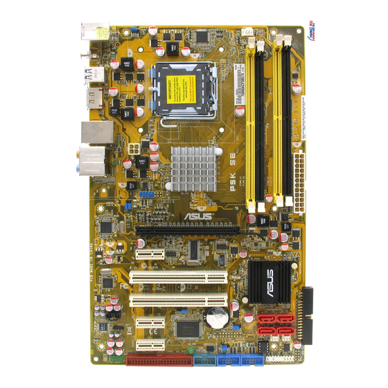
Page 24: Motherboard Overview
Motherboard overview Before you install the motherboard, study the configuration of your chassis to ensure that the motherboard fits into it. Make sure to unplug the power cord before installing or removing the motherboard. Failure to do so can cause you physical injury and damage motherboard components.
-
Page 25: Motherboard Layout
Lithium Cell PCIEX1_1 CMOS Power SATA2 SATA1 Super ALC883 SPDIF_OUT CLRTC PWR_FAN PCIEX1_2 USBPW9-12 CHA_FAN BIOS SB_PWR PRI_EIDE COM1 USB1112 USB910 AAFP PANEL Refer to 2.7 Connectors for more information about rear panel connectors and internal connectors. ASUS P5K SE/EPU…
-
Page 26: Layout Contents
2.2.4 Layout contents Slots Page DDR2 DIMM slots 2-13 PCI slots 2-21 PCI Express x1 slot 2-21 PCI Express x16 slots 2-21 Jumper Page Clear RTC RAM (3-pin CLRTC) 2-22 Keyboard power (3-pin PS2_USBPW) 2-23 USB device wake-up (3-pin USBPW1-4, USBPW5-8, USB9-12) 2-23 Rear panel connectors Page…
- Page 27
• System power LED (2-pin PLED) • Hard disk drive activity LED (2-pin IDE_LED) • System warning speaker (4-pin SPEAKER) • ATX power button/soft-off button (2-pin PWRSW) • Reset button (2-pin RESET) ASUS Q-connector (system panel) 2-35 ASUS P5K SE/EPU… -
Page 28: Central Processing Unit (Cpu)
ASUS will shoulder the cost of repair only if the damage is shipment/transit-related. • Keep the cap after installing the motherboard. ASUS will process Return Merchandise Authorization (RMA) requests only if the motherboard comes with the cap on the LGA775 socket.
-
Page 29: Installing The Cpu
This side of the socket box should face you. To prevent damage to the socket pins, do not remove the PnP cap unless you are installing a CPU. Lift the load lever in the direction of the arrow to a 135º angle. ASUS P5K SE/EPU…
- Page 30
Lift the load plate with your thumb and forefinger to a 100º angle (A), then push the PnP cap from the load plate window to remove (B). Load plate Alignment key Position the CPU over the socket, making sure that the gold triangle is on the bottom-left corner of the socket then fit the socket… -
Page 31: Installing The Cpu Heatsink And Fan
CPU fan connector. Motherboard hole Fastener Narrow end of the groove Make sure to orient each fastener with the narrow end of the groove pointing outward. (The photo shows the groove shaded for emphasis.) ASUS P5K SE/EPU…
- Page 32
Push down two fasteners at a time in a diagonal sequence to secure the heatsink and fan assembly in place. Connect the CPU fan cable to the connector on the motherboard labeled CPU_FAN. CPU_FAN ® P5K SE/EPU CPU fan connector Do not forget to connect the CPU fan connector! Hardware monitoring errors can occur if you fail to plug this connector. - Page 33
Rotate each fastener counterclockwise. Pull up two fasteners at a time in a diagonal sequence to disengage the heatsink and fan assembly from the motherboard. Carefully remove the heatsink and fan assembly from the motherboard. ASUS P5K SE/EPU 2-11… - Page 34
Rotate each fastener clockwise to ensure correct orientation when reinstalling. Narrow end of the groove The narrow end of the groove should point outward after resetting. (The photo shows the groove shaded for emphasis.) Refer to the documentation in the boxed or stand-alone CPU fan package for detailed information on CPU fan installation. -
Page 35: System Memory
The motherboard comes with four Double Data Rate 2 (DDR2) Dual Inline Memory Modules (DIMM) sockets. The figure illustrates the location of the DDR2 DIMM sockets: ® P5K SE/EPU 240-pin DDR2 DIMM sockets Channel Sockets Channel A DIMM_A1 and DIMM_B1 Channel B DIMM_A2 and DIMM_B2 ASUS P5K SE/EPU 2-13…
-
Page 36: Memory Configurations
2.4.2 Memory configurations You may install 256 MB, 512 MB, 1 GB, and 2 GB unbuffered non-ECC DDR2 DIMMs into the DIMM sockets. Recommended Memory Configurations Sockets Mode DIMM_A1 DIMM_A2 DIMM_B1 DIMM_B2 Populated Single-Channel Populated Dual-channel (1) Populated Populated Dual-channel (2) Populated Populated Populated…
- Page 37
CM2X1024 — 9136C5D / XMS9105V1.1 • If you install a DDR2-1066 memory module whose SPD is DDR2-800, make sure that you set the DRAM Frequency item in BIOS to [DDR2-1066MHz]. See section 4.4.1 Jumperfree Configuration for details. ASUS P5K SE/EPU 2-15… - Page 38
P5K SE/EPU Motherboard Qualified Vendors Lists (QVL) DDR2-800 MHz capability DIMM support Chip Size Vendor Chip No. Part No. Brand 512MB KINGSTON K4T51083QC KVR800D2N5/512 • • • 1024MB KINGSTON Heat-Sink Package 4-4-4-12 KHX6400D2LL/1G • • 1024MB KINGSTON Heat-Sink Package 4-4-4-12 KHX6400D2LLK2/1GN •… -
Page 39: Asus P5K Se/Epu
Dual-channel memory configuration. • C*: Supports 4 modules inserted into both the yellow and black slots as two pairs of Dual-channel memory configuration. Visit the ASUS website for the latest DDR2-1066/800/667MHz QVL. ASUS P5K SE/EPU 2-17…
-
Page 40: Installing A Dimm
2.4.3 Installing a DIMM Unplug the power supply before adding or removing DIMMs or other system components. Failure to do so can cause severe damage to both the motherboard and the components. To install a DIMM: DDR2 DIMM notch Unlock a DIMM socket by pressing the retaining clips outward.
-
Page 41: Expansion Slots
IRQ” or that the cards do not need IRQ assignments. Otherwise, conflicts will arise between the two PCI groups, making the system unstable and the card inoperable. Refer to the table on the next page for details. ASUS P5K SE/EPU 2-19…
-
Page 42: Interrupt Assignments
2.5.3 Interrupt assignments Standard function System timer Keyboard controller Re-direct to IRQ#9 IRQ holder for PCI steering* Communications port (COM1)* IRQ holder for PCI steering* Floppy disk controller IRQ holder for PCI steering* System CMOS/Real Time Clock IRQ holder for PCI steering* IRQ holder for PCI steering* IRQ holder for PCI steering* IRQ holder for PCI steering*…
-
Page 43: Pci Slots
PCI Express x1 slot. 2.5.6 PCI Express x16 slot This motherboard supports one PCI Express x16 graphics card that complies with the PCI Express specifications. The figure shows a graphics card installed on the PCI Express x16 slot. ASUS P5K SE/EPU 2-21…
-
Page 44: Clear Rtc Ram
Jumpers Clear RTC RAM (3-pin CLRTC) This jumper allows you to clear the Real Time Clock (RTC) RAM in CMOS. You can clear the CMOS memory of date, time, and system setup parameters by erasing the CMOS RTC RAM data. The onboard button cell battery powers the RAM data in CMOS, which include system setup information such as system passwords.
- Page 45
500mA on the +5VSB lead for each USB port; otherwise, the system would not power up. • The total current consumed must NOT exceed the power supply capability (+5VSB) whether under normal condition or in sleep mode. ASUS P5K SE/EPU 2-23… -
Page 46: Connectors
Connectors 2.7.1 Rear panel connectors PS/2 keyboard port (purple). This port is for a PS/2 keyboard. LAN (RJ-45) port. Supported by Gigabit LAN controller, this port allows Gigabit connection to a Local Area Network (LAN) through a network hub. Refer to the table below for the LAN port LED indications. Center/Subwoofer port (orange).
- Page 47
12. Coaxial S/PDIF Out port. This port connects an external audio output device via a coaxial S/PDIF cable. 13. USB 2.0 ports 5 and 6. These two 4-pin Universal Serial Bus (USB) ports are available for connecting USB 2.0 devices. ASUS P5K SE/EPU 2-25… -
Page 48: Internal Connectors
2.7.2 Internal connectors Floppy disk drive connector (34-1 pin FLOPPY) This connector is for the provided floppy disk drive (FDD) signal cable. Insert one end of the cable to this connector, then connect the other end to the signal connector at the back of the floppy disk drive. Pin 5 on the connector is removed to prevent incorrect cable connection when using a FDD cable with a covered Pin 5.
- Page 49
If any device jumper is set as “Cable-Select,” make sure all other device jumpers have the same setting. ® PRI_EIDE PIN 1 NOTE: Orient the red markings (usually zigzag) on the IDE ribbon cable to PIN 1. P5K SE/EPU IDE connector ASUS P5K SE/EPU 2-27… - Page 50
ICH9 Serial ATA connectors (7-pin SATA1-4) These connectors are for the Serial ATA signal cables for Serial ATA hard disk drives. SATA3 SATA4 SATA1 SATA2 SATA3 SATA4 ® P5B SATA Connectors SATA2 SATA1 P5K SE/EPU SATA connectors When using the connectors in Standard IDE mode, connect the primary (boot) hard disk drive to the SATA1/2 connector. - Page 51
Connect the S/PDIF Out module cable to this connector, then install the module to a slot opening at the back of the system chassis. ® SPDIF_OUT P5K SE/EPU Digital audio connector The S/PDIF module is purchased separately. ASUS P5K SE/EPU 2-29… -
Page 52: Usb Connectors
Never connect a 1394 cable to the USB connectors. Doing so will damage the motherboard! You can connect the front panel USB cable to the ASUS Q-Connector (USB, blue) first, and then install the Q-Connector (USB) to the USB connector onboard if your chassis supports front panel USB ports.
- Page 53
® PWR_FAN CHA_FAN P5K SE/EPU Fan connectors Only the CPU_FAN and CHA_FAN connector support the ASUS Q-FAN 2 feature. Serial port connector (10-1 pin COM1) This connector is for a serial (COM) port. Connect the serial port module cable to this connector, then install the module to a slot opening at the back of the system chassis. -
Page 54: Chassis Intrusion Connector
Chassis intrusion connector (4-1 pin CHASSIS) This connector is for a chassis-mounted intrusion detection sensor or switch. Connect one end of the chassis intrusion sensor or switch cable to this connector. The chassis intrusion sensor or switch sends a high-level signal to this connector when a chassis component is removed or replaced.
- Page 55
CPU: Intel Pentium Extreme 3.73GHz ® ® Memory: 512 MB DDR2 (x4) Graphics card: ASUS EAX1900XT Parallel ATA device: IDE hard disk drive Serial ATA device: SATA hard disk drive (x2) Optical drive: DVD-RW ASUS P5K SE/EPU 2-33… -
Page 56: System Panel Connector
12. System panel connector (20-8 pin PANEL) This connector supports several chassis-mounted functions. PLED SPEAKER PANEL ® RESET IDE_LED PWRSW Requires an ATX power supply. P5K SE/EPU System panel connector • System power LED (2-pin PLED) This 2-pin connector is for the system power LED. Connect the chassis power LED cable to this connector.
- Page 57
Q-Connector (system panel) You can use ASUS Q-Connector to connect / disconnect chassis front panel cables by only a few steps. Directions below shows how to install ASUS Q-Connector. Step1. Connect correct front panel to ASUS Q-Connector first. You can refer to the marking on Q-Connector itself to know the detail pin definition. - Page 58
2-36 Chapter 2: Hardware information… -
Page 59: Chapter 3: Powering Up
This chapter describes the power up sequence, the vocal POST messages, and ways of shutting down the system. Chapter 3: Powering up…
- Page 60
Chapter summary Starting up for the first time …………3-1 Turning off the computer …………. 3-2 ASUS P5K SE/EPU… -
Page 61: Starting Up For The First Time
One continuous beep followed by three No VGA detected short beeps One continuous beep followed by four Hardware component failure short beeps At power on, hold down the <Delete> key to enter the BIOS Setup. Follow the instructions in Chapter 4. ASUS P5K SE/EPU…
-
Page 62: Turning Off The Computer
Turning off the computer 3.2.1 Using the OS shut down function If you are using Windows ® Click the Start button then select Turn Off Computer. Click the Turn Off button to shut down the computer. The power supply should turn off after Windows ®…
-
Page 63: Chapter 4: Bios Setup
This chapter tells how to change the system settings through the BIOS Setup menus. Detailed descriptions of the BIOS parameters are also provided. Chapter 4: BIOS setup…
- Page 64
Chapter summary Managing and updating your BIOS ……….4-1 BIOS setup program …………..4-9 Main menu ……………… 4-12 Advanced menu …………….. 4-16 Power menu …………….4-25 Boot menu ……………… 4-29 Tools menu …………….. 4-33 Exit menu ………………4-35 ASUS P5K SE/EPU… -
Page 65: Managing And Updating Your Bios
ASUS Update (Updates the BIOS in Windows environment.) ® ASUS EZ Flash 2 (Updates the BIOS using a floppy disk or USB flash disk.) AFUDOS utility (Updates the BIOS using a bootable floppy disk.) ASUS CrashFree BIOS 3 (Updates the BIOS using a bootable floppy disk, USB flash disk or the motherboard support CD when the BIOS file fails or gets corrupted.)
- Page 66
To update the BIOS through the Internet: desktop by clicking Start Launch the ASUS Update utility from the Windows ® > Programs > ASUS > ASUSUpdate > ASUSUpdate. The ASUS Update main window appears. Select Update BIOS from the Select the ASUS FTP site nearest… - Page 67
To update the BIOS through a BIOS file: desktop by clicking Start Launch the ASUS Update utility from the Windows ® > Programs > ASUS > ASUSUpdate > ASUSUpdate. The ASUS Update main window appears. Select Update BIOS from a file option from the drop-down menu, then click Next. -
Page 68: Creating A Bootable Floppy Disk
4.1.2 Creating a bootable floppy disk Do either one of the following to create a bootable floppy disk. DOS environment a. Insert a 1.44MB floppy disk into the drive. b. At the DOS prompt, type format A:/S then press <Enter>. Windows XP environment ®…
-
Page 69: Asus Ez Flash 2 Utility
4.1.3 ASUS EZ Flash 2 utility The ASUS EZ Flash 2 feature allows you to update the BIOS without having to go through the long process of booting from a floppy disk and using a DOS-based utility. The EZ Flash 2 utility is built-in the BIOS chip so it is accessible by pressing <Alt>…
-
Page 70: Afudos Utility
Updating the BIOS file To update the BIOS file using the AFUDOS utility: Visit the ASUS website (www.asus.com) and download the latest BIOS file for the motherboard. Save the BIOS file to a bootable floppy disk. Chapter 4: BIOS setup…
- Page 71
A:>afudos /iP5KSE.ROM The utility verifies the file and starts updating the BIOS. A:>afudos /iP5KSE.ROM AMI Firmware Update Utility — Version 1.19(ASUS V2.07(03.11.24BB)) Copyright (C) 2002 American Megatrends, Inc. All rights reserved. WARNING!! Do not turn off power during flash BIOS Reading file .. -
Page 72: Asus Crashfree Bios 3 Utility
4.1.5 ASUS CrashFree BIOS 3 utility The ASUS CrashFree BIOS 3 is an auto recovery tool that allows you to restore the BIOS file when it fails or gets corrupted during the updating process. You can update a corrupted BIOS file using the motherboard support CD or a USB flash disk that contains the updated BIOS file.
-
Page 73: Bios Setup Program
The BIOS setup screens shown in this section are for reference purposes only, and may not exactly match what you see on your screen. • Visit the ASUS website (www.asus.com) to download the latest BIOS file for this motherboard. ASUS P5K SE/EPU…
-
Page 74: Bios Menu Screen
4.2.1 BIOS menu screen Menu items Menu bar Configuration fields General help BIOS SETUP UTILITY Main Advanced Power Boot Tools Exit Use [ENTER], [TAB] or System Time [10:55:25] [SHIFT-TAB] to select System Date [Mon 01/28/2008] a field. Legacy Diskette A [1.44M, 3.5 in] Use [+] or [-] to configure system Time.
-
Page 75: Menu Items
Up/Down arrow keys or <Page Up> /<Page Down> keys to display the other items on the screen. 4.2.9 General help Pop-up window At the top right corner of the menu screen Scroll bar is a brief description of the selected item. ASUS P5K SE/EPU 4-11…
-
Page 76: Main Menu
Main menu When you enter the BIOS Setup program, the Main menu screen appears, giving you an overview of the basic system information. Refer to section 4.2.1 BIOS menu screen for information on the menu screen items and how to navigate through them. BIOS SETUP UTILITY Main Advanced…
-
Page 77: Sata 1-4
When set to [Disabled], the data transfer from and to the device occurs one sector at a time. Configuration options: [Disabled] [Auto] PIO Mode [Auto] Selects the PIO mode. Configuration options: [Auto] [0] [1] [2] [3] [4] ASUS P5K SE/EPU 4-13…
-
Page 78: Sata Configuration
DMA Mode [Auto] Selects the DMA mode. Configuration options: [Auto] [SWDMA0] [SWDMA1] [SWDMA2] [MWDMA0] [MWDMA1] [MWDMA2] [UDMA0] [UDMA1] [UDMA2] [UDMA3] [UDMA4] [UDMA5] SMART Monitoring [Auto] Sets the Smart Monitoring, Analysis, and Reporting Technology. Configuration options: [Auto] [Disabled] [Enabled] 32Bit Data Transfer [Enabled] Enables or disables 32-bit data transfer.
-
Page 79: System Information
Available : 1024 MB General Help Save and Exit Exit v02.58 (C)Copyright 1985-2007, American Megatrends, Inc. AMI BIOS Displays the auto-detected BIOS information. Processor Displays the auto-detected CPU specification. System Memory Displays the auto-detected system memory. ASUS P5K SE/EPU 4-15…
-
Page 80: Advanced Menu
Advanced menu The Advanced menu items allow you to change the settings for the CPU and other system devices. Take caution when changing the settings of the Advanced menu items. Incorrect field values can cause the system to malfunction. BIOS SETUP UTILITY Main Advanced Power…
- Page 81
Allows you to set the DDR2 operating frequency. Configuration options: [Auto] [DDR2-667MHz] [DDR2-800MHz] [DDR2-1066MHz] [DDR2-1200MHz] Selecting a very high DRAM frequency may cause the system to become unstable! If this happens, revert to the default setting. ASUS P5K SE/EPU 4-17… - Page 82
DRAM Timing Control [Auto] Allows you to set the DRAM timing control. Configuration options: [Auto] [MANUAL] The following items appear when you set the DRAM Timing Control item to [Manual]. CAS# Latency [ 5] Configuration options: [3] [4] [5] [6] RAS# to CAS# Delay [ 5 DRAM Clocks] Configuration options: [3 DRAM Clocks] [4 DRAM Clocks]~[9 DRAM Clocks] [10 DRAM Clocks]… -
Page 83: Ai Net 2
Allows you to enable or disable LAN cable check during POST. When enabled, the menu reports the cable faults or shorts, and displays the point (length) where the faults or shorts are detected. Configuration options: [Disabled] [Enabled] ASUS P5K SE/EPU 4-19…
-
Page 84: Usb Configuration
4.4.3 USB Configuration The items in this menu allows you to change the USB-related features. Select an item then press <Enter> to display the configuration options. BIOS SETUP UTILITY Advanced USB Configuration Options USB Devices Enabled: Disabled None Enhanced USB Functions [Enabled] USB 2.0 Controller [Enabled]…
-
Page 85: Cpu Configuration
Allows you to enable or disable C1E Support. Configuration options: [Disabled] [Enabled] Max CPUID Value Limit [Disabled] Setting this item to [Enabled] allows legacy operating systems to boot even without support for CPUs with extended CPUID functions. Configuration options: [Disabled] [Enabled] ASUS P5K SE/EPU 4-21…
-
Page 86: Chipset
Vanderpool Technology [Enabled] Configuration options: [Enabled] [Disabled] CPU TM Function [Enabled] Configuration options: [Disabled] [Enabled] Execute Disable Bit [Enabled] Allows you to enable or disable the No-Execution Page Protection Technology. Setting this item to [Disabled] forces the XD feature flag to always return to zero (0).
-
Page 87: Onboard Devices Configuration
AC’97 or high-definition audio depending on the audio standard that the front panel audio module supports. Configuration options: [AC97] [HD Audio] Marvell IDE Controller [Enabled] Allows you to disable or enable the onboard Marvell IDE controller. ® Configuration options: [Enabled] [Disabled] ASUS P5K SE/EPU 4-23…
-
Page 88: Pci Pnp
Onboard PCIE GbE LAN [Enabled] Configuration options: [Enabled] [Disabled] LAN Option ROM [Disabled] This item appears only when you enable the previous item. Configuration options: [Disabled] [Enabled] Serial Port1 Address [3F8/IRQ4] Allows you to select the Serial Port1 base address. Configuration options: [Disabled] [3F8/IRQ4] [2F8/IRQ3] [3E8/IRQ4] [2E8/IRQ3] 4.4.7 PCI PnP…
-
Page 89: Power Menu
Allows you to enable or disable the Advanced Configuration and Power Interface (ACPI) support in the Advanced Programmable Interrupt Controller (APIC). When set to Enabled, the ACPI APIC table pointer is included in the RSDT pointer list. Configuration options: [Disabled] [Enabled] ASUS P5K SE/EPU 4-25…
-
Page 90: Apm Configuration
4.5.5 APM Configuration BIOS SETUP UTILITY Power APM Configuration <Enter> to select whether or not to restart the system after AC power loss. Restore on AC Power Loss [Power Off] Power On By RTC Alarm [Disabled] Power On By External Modems [Disabled] Power On By PCI Devices [Disabled]…
-
Page 91: Hardware Monitor
N/A. CPU Q-Fan Control [Disabled] Allows you to enable or disable the CPU Q-Fan controller. Configuration options: [Disabled] [Enabled] The CPU Fan Profile item appears when you enable the CPU Q-Fan Control feature. ASUS P5K SE/EPU 4-27…
- Page 92
CPU Fan Profile [Optimal] Allows you to set the appropriate performance level of the CPU Q-Fan. When set to [Optimal], the CPU fan automatically adjusts depending on the CPU temperature. Set this item to [Silent Mode] to minimize fan speed for quiet CPU fan operation, or [Performance Mode] to achieve maximum CPU fan speed. -
Page 93: Boot Menu
These items specify the boot device priority sequence from the available devices. The number of device items that appears on the screen depends on the number of devices installed in the system. Configuration options: [1st FLOPPY DRIVE] [Hard Drive] [ATAPI CD-ROM] [Disabled] ASUS P5K SE/EPU 4-29…
-
Page 94: Boot Settings Configuration
Configuration options: [Disabled] [Enabled] Full Screen Logo [Enabled] This allows you to enable or disable the full screen logo display feature. Configuration options: [Disabled] [Enabled] Set this item to [Enabled] to use the ASUS MyLogo2 feature. ™ AddOn ROM Display Mode [Force BIOS] Sets the display mode for option ROM.
-
Page 95: Security
Time Clock (RTC) RAM. See section 2.6 Jumper for information on how to erase the RTC RAM. After you have set a supervisor password, the other items appear to allow you to change other security settings. ASUS P5K SE/EPU 4-31…
-
Page 96: Change User Password
BIOS SETUP UTILITY Boot <Enter> to change Security Settings password. <Enter> again to Supervisor Password :Installed disabled password. User Password :Installed Change Supervisor Password User Access Level [Full Access] Change User Password Clear User Password Password Check [Setup] Select Screen Select Item Enter Change General Help…
-
Page 97: Tools Menu
4.7.1 ASUS EZ Flash 2 Allows you to run ASUS EZ Flash 2. When you press <Enter>, a confirmation message appears. Use the left/right arrow key to select between [Yes] or [No], then press <Enter> to confirm your choice. Please see section 4.1.3 for details.
-
Page 98: Asus O.c. Profile
Start O.C. Profile Allows you to run the utility to save and load CMOS. Press <Enter> to run the utility. ASUSTek O.C. Profile Utility V1.05 Current CMOS Restore CMOS BOARD: P5K SE EPU BOARD: Unknown VER: 0110 VER: Unknown DATE:…
-
Page 99: Exit Menu
Setup menus. When you select this option or if you press <F5>, a confirmation window appears. Select Ok to load default values. Select Exit & Save Changes or make other changes before saving the values to the non-volatile RAM. ASUS P5K SE/EPU 4-35…
- Page 100
4-36 Chapter 4: BIOS setup… -
Page 101: Chapter 5: Software Support
This chapter describes the contents of the support CD that comes with the motherboard package. Software Chapter 5: support…
- Page 102
Chapter summary Installing an operating system ……….. 5-1 Support CD information ………….. 5-1 Software information …………..5-8 ASUS P5K SE/EPU… -
Page 103: Installing An Operating System
The contents of the support CD are subject to change at any time without notice. Visit the ASUS website (www.asus.com) for updates. 5.2.1 Running the support CD Place the support CD to the optical drive.
-
Page 104: Drivers Menu
6111 Serial ATA controller driver. ® USB 2.0 Driver Installs the Universal Serial Bus 2.0 (USB 2.0) driver. AI Gear 3+ Driver Installs the EPU and AI Gear 3 driver. Install this driver before the ASUS AI Suite utility. Chapter 5: Software support…
-
Page 105: Utilities Menu
Installs all of the utilities through the Installation Wizard. ASUS Update Allows you to download the latest version of the BIOS from the ASUS website. Before using the ASUS Update, make sure that you have an Internet connection so you can connect to the ASUS website.
- Page 106
You can also install the following utilities from the ASUS Superb Software Library CD. ADOBE Acrobat Reader V7.0 Installs the Adobe Acrobat Reader that allows you to open, view, and print ® ® documents in Portable Document Format (PDF). Microsoft DirectX 9.0c Installs the Microsoft DirectX 9.0 driver. -
Page 107: Manual Menu
Reader from the ASUS Superb Software Library CD before ® ® opening a user manual file. 5.2.5 ASUS Contact information Click the Contact tab to display the ASUS contact information. You can also find this information on the inside front cover of this user guide. ASUS P5K SE/EPU…
-
Page 108: Other Information
5.2.6 Other information The icons on the top right corner of the screen give additional information on the motherboard and the contents of the support CD. Click an icon to display the specified information. Motherboard Info Displays the general specifications of the motherboard. Browse this CD Displays the support CD contents in graphical format.
-
Page 109: Technical Support Form
Technical support Form Displays the ASUS Technical Support Request Form that you have to fill out when requesting technical support. Filelist Displays the contents of the support CD and a brief description of each in text format. ASUS P5K SE/EPU…
-
Page 110: Software Information
5.3.1 ASUS MyLogo2™ The ASUS MyLogo2™ utility lets you customize the boot logo. The boot logo is the image that appears on screen during the Power-On Self-Tests (POST). The ASUS MyLogo2™ is automatically installed when you install the ASUS Update utility from the Support CD.
- Page 111
Ratio box. When the screen returns to the ASUS Update utility, flash the original BIOS to load the new boot logo. 10. After flashing the BIOS, restart the computer to display the new boot logo during POST. -
Page 112: Audio Configurations
5.3.2 Audio configurations The Realtek ALC883 audio CODEC provides 8-channel audio capability to deliver ® the ultimate audio experience on your computer. The software provides Jack- Sensing function, S/PDIF Out support, and interrupt capability. The ALC883 also includes the Realtek ®…
-
Page 113: Configuration Options
Click the shortcut buttons or the drop-down menus for options on changing the acoustic environment, adjust the equalizer, or set the karaoke to your desired settings. Click to effect the Sound Effect settings and exit. ASUS P5K SE/EPU 5-11…
- Page 114
Mixer The Mixer option allows you to configure audio output (playback) volume and audio input (record) volume. To set the mixer options: From the Realtek HD Audio Manager, click the Mixer tab. Turn the volume buttons to adjust the Playback and/or Record volume. - Page 115
From the Realtek HD Audio Manager, click the 3D Audio Demo tab. Click the option buttons to change the sound, moving path, or environment settings. Click to test your settings. Click to effect the 3D Audio Demo settings and exit. ASUS P5K SE/EPU 5-13… -
Page 116: Asus Pc Probe Ii
To launch the PC Probe II from the Windows ® > ASUS > PC Probe II > PC Probe II v1.xx.xx. The PC Probe II main window appears. After launching the application, the PC Probe II icon appears in the Windows ®…
- Page 117
When a system sensor detects a problem, the main window right handle turns red, as the illustrations below show. When displayed, the monitor panel for that sensor also turns red. Refer to the Monitor panels section for details. ASUS P5K SE/EPU 5-15… - Page 118
Hardware monitor panels The hardware monitor panels display the current value of a system sensor such as fan rotation, CPU temperature, and voltages. The hardware monitor panels come in two display modes: hexagonal (large) and rectangular (small). When you check the Enable Monitoring Panel option from the Preference section, the monitor panels appear on your computer’s desktop. - Page 119
You can enlarge or reduce the browser size by dragging the bottom right corner of the browser. DMI browser Click to display the DMI (Desktop Management Interface) browser. This browser displays various desktop and system information. Click the plus sign (+) before DMI Information to display the available information. ASUS P5K SE/EPU 5-17… - Page 120
PCI browser Click to display the PCI (Peripheral Component Interconnect) browser. This browser provides information on the PCI devices installed on your system. Click the plus sign (+) before the PCI Information item to display available information. Usage The Usage browser displays real-time information on the CPU, hard disk drive space, and memory usage. - Page 121
The Preference tab allows you to customize sensor alerts, or change the temperature scale. Loads the default Loads your saved threshold values for Cancels or configuration each sensor ignores your changes Applies your Saves your changes configuration ASUS P5K SE/EPU 5-19… -
Page 122: Asus Ai Suite
ASUS AI Suite allows you to launch AI Gear 3 , AI Booster, AI Nap, and Q-Fan 2 utilities easily. Install the AI Gear 3+ Driver before the ASUS AI Suite utility. Otherwise, the ASUS AI Suite will not function properly. Installing AI Suite To install AI Suite on your computer: Place the support DVD to the optical drive.
- Page 123
Displays the CPU/ system temperature, CPU/memory/PCIE voltage, and CPU/ chassis fan speed Displays the FSB/CPU frequency Click on right corner of the expanded window to switch the temperature from degrees Centigrade to degrees Fahrenheit. ASUS P5K SE/EPU 5-21… -
Page 124: Asus Epu Utility — Ai Gear 3
After installing ASUS AI Suite from the bundled support DVD, you can launch ASUS AI Gear 3 by double-clicking the AI Suite icon on your Windows OS taskbar and then click the AI Gear 3 button on the AI Suite main window.
- Page 125
Electricity Savings Calculator window. You may reset the Click time for the calculator to start counting. Click to reset the time the calculator starts Displays the electricity saved since the time was reset ASUS P5K SE/EPU 5-23… -
Page 126: Asus Ai Nap
5.3.6 ASUS AI Nap This feature allows you to minimize the power consumption of your computer whenever you are away. Enable this feature for minimum power consumption and a more quiet system operation. After installing AI Suite from the bundled support CD, you can launch the utility by double-clicking the AI Suite icon on the Windows OS taskbar and click the AI Nap button on the AI Suite main window.
-
Page 127: Asus Q-Fan 2
5.3.7 ASUS Q-Fan 2 This ASUS Q-Fan 2 Control feature allows you to set the appropriate performance level of the CPU Q-Fan 2 or the Chassis Q-Fan 2 for more efficient system operation. After enabling the Q-Fan 2 function, the fans can be set to automatically adjust depending on the temperature, to decrease fan speed, or to achieve the maximum fan speed.
-
Page 128: Asus Ai Booster
5.3.8 ASUS AI Booster The ASUS AI Booster application allows you to overclock the CPU speed in WIndows environment without the hassle of booting the BIOS. ® After installing AI Suite from the bundled support CD, you can launch the utility…
-
Page 129: Appendix: Cpu Features
The Appendix describes the CPU features and technologies that the motherboard supports. Appendix: CPU features…
-
Page 130: A.1 Intel ® Em64T
Chapter summary Intel ® EM64T ………………A-1 Enhanced Intel SpeedStep Technology (EIST) ……A-1 ® Intel Hyper-Threading Technology ………..A-3 ® ASUS P5K SE/EPU…
-
Page 131: Intel ® Em64T
32-bit operating systems. • The motherboard comes with a BIOS file that supports EM64T. You can download the latest BIOS file from the ASUS website (www.asus.com/ support/download/) if you need to update the BIOS file. See Chapter 4 for details.
-
Page 132: Using The Eist
A.2.2 Using the EIST To use the EIST feature: Turn on the computer, then enter the BIOS Setup. Go to the Advanced Menu, highlight CPU Configuration, then press <Enter>. Set the Intel(R) SpeedStep Technology item to [Automatic], then press <Enter>. Press <F10>…
-
Page 133: Intel ® Hyper-Threading Technology
Power up the system and enter the BIOS Setup. Under the Advanced Menu, make sure that the item Hyper-Threading Technology is set to [Enabled]. The BIOS item appears only if you installed a CPU that supports Hyper-Threading Technology. Restart the computer. ASUS P5K SE/EPU…
- Page 134
Appendix: CPU features…
-
Contents
-
Table of Contents
-
Bookmarks
Quick Links
Related Manuals for Asus P5K SE EPU
Summary of Contents for Asus P5K SE EPU
-
Page 1
P5K SE/EPU… -
Page 2
Product warranty or service will not be extended if: (1) the product is repaired, modified or altered, unless such repair, modification of alteration is authorized in writing by ASUS; or (2) the serial number of the product is defaced or missing. -
Page 3: Table Of Contents
Welcome! ………………1-1 Package contents …………….. 1-1 Special features …………….1-2 1.3.1 Product highlights …………1-2 1.3.2 ASUS AI Lifestyle features ……….1-4 1.3.3 ASUS Stylish features …………. 1-5 1.3.4 ASUS Intelligent Overclocking features ……1-6 Chapter 2: Hardware information Before you proceed …………..
-
Page 4: Contents
4.1.1 ASUS Update utility …………4-1 4.1.2 Creating a bootable floppy disk ……..4-4 4.1.3 ASUS EZ Flash 2 utility ……….. 4-5 4.1.4 AFUDOS utility …………..4-6 4.1.5 ASUS CrashFree BIOS 3 utility ……..4-8 BIOS setup program …………..4-9 4.2.1…
-
Page 5
4.6.2 Boot Settings Configuration ………. 4-30 4.6.3 Security …………….. 4-31 Tools menu …………….. 4-33 4.7.1 ASUS EZ Flash 2 …………4-33 4.7.2 ASUS O.C. Profile …………4-34 Exit menu ………………4-35 Chapter 5: Software support Installing an operating system ……….. 5-1 Support CD information ………….. -
Page 6
Contents 5.3.3 ASUS PC Probe II …………5-14 5.3.4 ASUS AI Suite …………… 5-20 5.3.5 ASUS EPU Utility — AI Gear 3 ……..5-22 5.3.6 ASUS AI Nap …………..5-24 5.3.7 ASUS Q-Fan 2 ………….. 5-25 5.3.8 ASUS AI Booster …………5-26… -
Page 7: Notices
Notices Federal Communications Commission Statement This device complies with Part 15 of the FCC Rules. Operation is subject to the following two conditions: • This device may not cause harmful interference, and • This device must accept any interference received including interference that may cause undesired operation.
-
Page 8: Safety Information
Safety information Electrical safety • To prevent electrical shock hazard, disconnect the power cable from the electrical outlet before relocating the system. • When adding or removing devices to or from the system, ensure that the power cables for the devices are unplugged before the signal cables are connected. If possible, disconnect all power cables from the existing system before you add a device.
-
Page 9: About This Guide
Refer to the following sources for additional information and for product and software updates. ASUS websites The ASUS website provides updated information on ASUS hardware and software products. Refer to the ASUS contact information. Optional documentation Your product package may include optional documentation, such as warranty flyers, that may have been added by your dealer.
-
Page 10: Conventions Used In This Guide
Conventions used in this guide To make sure that you perform certain tasks properly, take note of the following symbols used throughout this manual. DANGER/WARNING: Information to prevent injury to yourself when trying to complete a task. CAUTION: Information to prevent damage to the components when trying to complete a task.
-
Page 11: P5K Se/Epu Specifications Summary
— 4 x 240-pin DIMM sockets support unbuffered non-ECC DDR2 1200/1066/800/667MHz memory modules — Supports up to 8 GB system memory * Refer to www.asus.com or this user manual for the Memory QVL (Qualified Vendors Lists). Expansion slots 1 x PCI Express™ x16 slot…
-
Page 12
System panel connector (Q-Connector) BIOS features 8 Mb Flash ROM, AMI BIOS, PnP, DMI 2.0, WfM 2.0, SM BIOS 2.3, ACPI 2.0a, ASUS EZ Flash 2, ASUS CrashFree BIOS 3 Manageability WfM 2.0, DMI 2.0, WOL by PME, WOR by PME, PXE… -
Page 13: Chapter 1: Product Introduction
This chapter describes the motherboard features and the new technologies it supports. Chapter 1: Product introduction…
-
Page 14
Chapter summary Welcome! ………………1-1 Package contents …………….. 1-1 Special features …………….1-2 ASUS P5K SE/EPU… -
Page 15: Welcome
® The motherboard delivers a host of new features and latest technologies, making it another standout in the long line of ASUS quality motherboards! Before you start installing the motherboard, and hardware devices on it, check the items in your package with the list below.
-
Page 16: Special Features
Green ASUS This motherboard and its packaging comply with the European Union’s Restriction on the use of Hazardous Substances (RoHS). This is in line with the ASUS vision of creating environment-friendly and recyclable products/packaging to safeguard consumers’ health while minimizing the impact on the environment.
-
Page 17: High Definition Audio
Audio CODEC enables high-quality 192KHz/24-bit audio output, jack-sensing feature, and multi-streaming technology that simultaneously sends different audio streams to different destinations. You can now talk to your partners on the headphone while playing multi-channel network games. See pages 2-24 and 2-25 for details. ASUS P5K SE/EPU…
-
Page 18: Asus Ai Lifestyle Features
1.3.2 ASUS AI Lifestyle features ASUS Power Saving Solution ASUS Power Saving solution makes system more stable and enhances the overclocking capability. ASUS EPU The ASUS EPU utilizes innovative technology to digitally monitor and tune the CPU power supply with improved VR responses in heavy or light loadings.
-
Page 19: Asus Stylish Features
Smart Support CD It provides a checklist to allow the user to see which drivers are already installed, as well as those that aren’t. When using ASUS PC Probe II, you can easily see the critical parts of the computer.
-
Page 20: Asus Intelligent Overclocking Features
1.3.4 ASUS Intelligent Overclocking features AI Booster The ASUS AI Booster allows you to overclock the CPU speed in Windows environment without the hassle of booting the BIOS. See page 5-26 for details. Precision Tweaker This feature allows you to fine tune the CPU/memory voltage and gradually increase the memory Front Side Bus (FSB) and PCI Express frequency at 1MHz increment to achieve maximum system performance.
-
Page 21: Chapter 2: Hardware Information
This chapter lists the hardware setup procedures that you have to perform when installing system components. It includes description of the jumpers and connectors on the motherboard. Chapter 2: Hardware information…
-
Page 22
Chapter summary Before you proceed …………..2-1 Motherboard overview …………..2-2 Central Processing Unit (CPU) ……….. 2-6 System memory …………….. 2-13 Expansion slots …………….2-19 Jumpers ………………2-22 Connectors …………….. 2-24 ASUS P5K SE/EPU… -
Page 23: Before You Proceed
The illustration below shows the location of the onboard LED. SB_PWR ® Standby Powered Power P5K SE/EPU Onboard LED ASUS P5K SE/EPU…
-
Page 24: Motherboard Overview
Motherboard overview Before you install the motherboard, study the configuration of your chassis to ensure that the motherboard fits into it. Make sure to unplug the power cord before installing or removing the motherboard. Failure to do so can cause you physical injury and damage motherboard components.
-
Page 25: Motherboard Layout
Lithium Cell PCIEX1_1 CMOS Power SATA2 SATA1 Super ALC883 SPDIF_OUT CLRTC PWR_FAN PCIEX1_2 USBPW9-12 CHA_FAN BIOS SB_PWR PRI_EIDE COM1 USB1112 USB910 AAFP PANEL Refer to 2.7 Connectors for more information about rear panel connectors and internal connectors. ASUS P5K SE/EPU…
-
Page 26: Layout Contents
2.2.4 Layout contents Slots Page DDR2 DIMM slots 2-13 PCI slots 2-21 PCI Express x1 slot 2-21 PCI Express x16 slots 2-21 Jumper Page Clear RTC RAM (3-pin CLRTC) 2-22 Keyboard power (3-pin PS2_USBPW) 2-23 USB device wake-up (3-pin USBPW1-4, USBPW5-8, USB9-12) 2-23 Rear panel connectors Page…
-
Page 27
• System power LED (2-pin PLED) • Hard disk drive activity LED (2-pin IDE_LED) • System warning speaker (4-pin SPEAKER) • ATX power button/soft-off button (2-pin PWRSW) • Reset button (2-pin RESET) ASUS Q-connector (system panel) 2-35 ASUS P5K SE/EPU… -
Page 28: Central Processing Unit (Cpu)
ASUS will shoulder the cost of repair only if the damage is shipment/transit-related. • Keep the cap after installing the motherboard. ASUS will process Return Merchandise Authorization (RMA) requests only if the motherboard comes with the cap on the LGA775 socket.
-
Page 29: Installing The Cpu
This side of the socket box should face you. To prevent damage to the socket pins, do not remove the PnP cap unless you are installing a CPU. Lift the load lever in the direction of the arrow to a 135º angle. ASUS P5K SE/EPU…
-
Page 30
Lift the load plate with your thumb and forefinger to a 100º angle (A), then push the PnP cap from the load plate window to remove (B). Load plate Alignment key Position the CPU over the socket, making sure that the gold triangle is on the bottom-left corner of the socket then fit the socket… -
Page 31: Installing The Cpu Heatsink And Fan
CPU fan connector. Motherboard hole Fastener Narrow end of the groove Make sure to orient each fastener with the narrow end of the groove pointing outward. (The photo shows the groove shaded for emphasis.) ASUS P5K SE/EPU…
-
Page 32
Push down two fasteners at a time in a diagonal sequence to secure the heatsink and fan assembly in place. Connect the CPU fan cable to the connector on the motherboard labeled CPU_FAN. CPU_FAN ® P5K SE/EPU CPU fan connector Do not forget to connect the CPU fan connector! Hardware monitoring errors can occur if you fail to plug this connector. -
Page 33
Rotate each fastener counterclockwise. Pull up two fasteners at a time in a diagonal sequence to disengage the heatsink and fan assembly from the motherboard. Carefully remove the heatsink and fan assembly from the motherboard. ASUS P5K SE/EPU 2-11… -
Page 34
Rotate each fastener clockwise to ensure correct orientation when reinstalling. Narrow end of the groove The narrow end of the groove should point outward after resetting. (The photo shows the groove shaded for emphasis.) Refer to the documentation in the boxed or stand-alone CPU fan package for detailed information on CPU fan installation. -
Page 35: System Memory
The motherboard comes with four Double Data Rate 2 (DDR2) Dual Inline Memory Modules (DIMM) sockets. The figure illustrates the location of the DDR2 DIMM sockets: ® P5K SE/EPU 240-pin DDR2 DIMM sockets Channel Sockets Channel A DIMM_A1 and DIMM_B1 Channel B DIMM_A2 and DIMM_B2 ASUS P5K SE/EPU 2-13…
-
Page 36: Memory Configurations
2.4.2 Memory configurations You may install 256 MB, 512 MB, 1 GB, and 2 GB unbuffered non-ECC DDR2 DIMMs into the DIMM sockets. Recommended Memory Configurations Sockets Mode DIMM_A1 DIMM_A2 DIMM_B1 DIMM_B2 Populated Single-Channel Populated Dual-channel (1) Populated Populated Dual-channel (2) Populated Populated Populated…
-
Page 37
CM2X1024 — 9136C5D / XMS9105V1.1 • If you install a DDR2-1066 memory module whose SPD is DDR2-800, make sure that you set the DRAM Frequency item in BIOS to [DDR2-1066MHz]. See section 4.4.1 Jumperfree Configuration for details. ASUS P5K SE/EPU 2-15… -
Page 38
P5K SE/EPU Motherboard Qualified Vendors Lists (QVL) DDR2-800 MHz capability DIMM support Chip Size Vendor Chip No. Part No. Brand 512MB KINGSTON K4T51083QC KVR800D2N5/512 • • • 1024MB KINGSTON Heat-Sink Package 4-4-4-12 KHX6400D2LL/1G • • 1024MB KINGSTON Heat-Sink Package 4-4-4-12 KHX6400D2LLK2/1GN •… -
Page 39: Asus P5K Se/Epu
Dual-channel memory configuration. • C*: Supports 4 modules inserted into both the yellow and black slots as two pairs of Dual-channel memory configuration. Visit the ASUS website for the latest DDR2-1066/800/667MHz QVL. ASUS P5K SE/EPU 2-17…
-
Page 40: Installing A Dimm
2.4.3 Installing a DIMM Unplug the power supply before adding or removing DIMMs or other system components. Failure to do so can cause severe damage to both the motherboard and the components. To install a DIMM: DDR2 DIMM notch Unlock a DIMM socket by pressing the retaining clips outward.
-
Page 41: Expansion Slots
IRQ” or that the cards do not need IRQ assignments. Otherwise, conflicts will arise between the two PCI groups, making the system unstable and the card inoperable. Refer to the table on the next page for details. ASUS P5K SE/EPU 2-19…
-
Page 42: Interrupt Assignments
2.5.3 Interrupt assignments Standard function System timer Keyboard controller Re-direct to IRQ#9 IRQ holder for PCI steering* Communications port (COM1)* IRQ holder for PCI steering* Floppy disk controller IRQ holder for PCI steering* System CMOS/Real Time Clock IRQ holder for PCI steering* IRQ holder for PCI steering* IRQ holder for PCI steering* IRQ holder for PCI steering*…
-
Page 43: Pci Slots
PCI Express x1 slot. 2.5.6 PCI Express x16 slot This motherboard supports one PCI Express x16 graphics card that complies with the PCI Express specifications. The figure shows a graphics card installed on the PCI Express x16 slot. ASUS P5K SE/EPU 2-21…
-
Page 44: Clear Rtc Ram
Jumpers Clear RTC RAM (3-pin CLRTC) This jumper allows you to clear the Real Time Clock (RTC) RAM in CMOS. You can clear the CMOS memory of date, time, and system setup parameters by erasing the CMOS RTC RAM data. The onboard button cell battery powers the RAM data in CMOS, which include system setup information such as system passwords.
-
Page 45
500mA on the +5VSB lead for each USB port; otherwise, the system would not power up. • The total current consumed must NOT exceed the power supply capability (+5VSB) whether under normal condition or in sleep mode. ASUS P5K SE/EPU 2-23… -
Page 46: Connectors
Connectors 2.7.1 Rear panel connectors PS/2 keyboard port (purple). This port is for a PS/2 keyboard. LAN (RJ-45) port. Supported by Gigabit LAN controller, this port allows Gigabit connection to a Local Area Network (LAN) through a network hub. Refer to the table below for the LAN port LED indications. Center/Subwoofer port (orange).
-
Page 47
12. Coaxial S/PDIF Out port. This port connects an external audio output device via a coaxial S/PDIF cable. 13. USB 2.0 ports 5 and 6. These two 4-pin Universal Serial Bus (USB) ports are available for connecting USB 2.0 devices. ASUS P5K SE/EPU 2-25… -
Page 48: Internal Connectors
2.7.2 Internal connectors Floppy disk drive connector (34-1 pin FLOPPY) This connector is for the provided floppy disk drive (FDD) signal cable. Insert one end of the cable to this connector, then connect the other end to the signal connector at the back of the floppy disk drive. Pin 5 on the connector is removed to prevent incorrect cable connection when using a FDD cable with a covered Pin 5.
-
Page 49
If any device jumper is set as “Cable-Select,” make sure all other device jumpers have the same setting. ® PRI_EIDE PIN 1 NOTE: Orient the red markings (usually zigzag) on the IDE ribbon cable to PIN 1. P5K SE/EPU IDE connector ASUS P5K SE/EPU 2-27… -
Page 50
ICH9 Serial ATA connectors (7-pin SATA1-4) These connectors are for the Serial ATA signal cables for Serial ATA hard disk drives. SATA3 SATA4 SATA1 SATA2 SATA3 SATA4 ® P5B SATA Connectors SATA2 SATA1 P5K SE/EPU SATA connectors When using the connectors in Standard IDE mode, connect the primary (boot) hard disk drive to the SATA1/2 connector. -
Page 51
Connect the S/PDIF Out module cable to this connector, then install the module to a slot opening at the back of the system chassis. ® SPDIF_OUT P5K SE/EPU Digital audio connector The S/PDIF module is purchased separately. ASUS P5K SE/EPU 2-29… -
Page 52: Usb Connectors
Never connect a 1394 cable to the USB connectors. Doing so will damage the motherboard! You can connect the front panel USB cable to the ASUS Q-Connector (USB, blue) first, and then install the Q-Connector (USB) to the USB connector onboard if your chassis supports front panel USB ports.
-
Page 53
® PWR_FAN CHA_FAN P5K SE/EPU Fan connectors Only the CPU_FAN and CHA_FAN connector support the ASUS Q-FAN 2 feature. Serial port connector (10-1 pin COM1) This connector is for a serial (COM) port. Connect the serial port module cable to this connector, then install the module to a slot opening at the back of the system chassis. -
Page 54: Chassis Intrusion Connector
Chassis intrusion connector (4-1 pin CHASSIS) This connector is for a chassis-mounted intrusion detection sensor or switch. Connect one end of the chassis intrusion sensor or switch cable to this connector. The chassis intrusion sensor or switch sends a high-level signal to this connector when a chassis component is removed or replaced.
-
Page 55
CPU: Intel Pentium Extreme 3.73GHz ® ® Memory: 512 MB DDR2 (x4) Graphics card: ASUS EAX1900XT Parallel ATA device: IDE hard disk drive Serial ATA device: SATA hard disk drive (x2) Optical drive: DVD-RW ASUS P5K SE/EPU 2-33… -
Page 56: System Panel Connector
12. System panel connector (20-8 pin PANEL) This connector supports several chassis-mounted functions. PLED SPEAKER PANEL ® RESET IDE_LED PWRSW Requires an ATX power supply. P5K SE/EPU System panel connector • System power LED (2-pin PLED) This 2-pin connector is for the system power LED. Connect the chassis power LED cable to this connector.
-
Page 57
Q-Connector (system panel) You can use ASUS Q-Connector to connect / disconnect chassis front panel cables by only a few steps. Directions below shows how to install ASUS Q-Connector. Step1. Connect correct front panel to ASUS Q-Connector first. You can refer to the marking on Q-Connector itself to know the detail pin definition. -
Page 58
2-36 Chapter 2: Hardware information… -
Page 59: Chapter 3: Powering Up
This chapter describes the power up sequence, the vocal POST messages, and ways of shutting down the system. Chapter 3: Powering up…
-
Page 60
Chapter summary Starting up for the first time …………3-1 Turning off the computer …………. 3-2 ASUS P5K SE/EPU… -
Page 61: Starting Up For The First Time
One continuous beep followed by three No VGA detected short beeps One continuous beep followed by four Hardware component failure short beeps At power on, hold down the <Delete> key to enter the BIOS Setup. Follow the instructions in Chapter 4. ASUS P5K SE/EPU…
-
Page 62: Turning Off The Computer
Turning off the computer 3.2.1 Using the OS shut down function If you are using Windows ® Click the Start button then select Turn Off Computer. Click the Turn Off button to shut down the computer. The power supply should turn off after Windows ®…
-
Page 63: Chapter 4: Bios Setup
This chapter tells how to change the system settings through the BIOS Setup menus. Detailed descriptions of the BIOS parameters are also provided. Chapter 4: BIOS setup…
-
Page 64
Chapter summary Managing and updating your BIOS ……….4-1 BIOS setup program …………..4-9 Main menu ……………… 4-12 Advanced menu …………….. 4-16 Power menu …………….4-25 Boot menu ……………… 4-29 Tools menu …………….. 4-33 Exit menu ………………4-35 ASUS P5K SE/EPU… -
Page 65: Managing And Updating Your Bios
ASUS Update (Updates the BIOS in Windows environment.) ® ASUS EZ Flash 2 (Updates the BIOS using a floppy disk or USB flash disk.) AFUDOS utility (Updates the BIOS using a bootable floppy disk.) ASUS CrashFree BIOS 3 (Updates the BIOS using a bootable floppy disk, USB flash disk or the motherboard support CD when the BIOS file fails or gets corrupted.)
-
Page 66
To update the BIOS through the Internet: desktop by clicking Start Launch the ASUS Update utility from the Windows ® > Programs > ASUS > ASUSUpdate > ASUSUpdate. The ASUS Update main window appears. Select Update BIOS from the Select the ASUS FTP site nearest… -
Page 67
To update the BIOS through a BIOS file: desktop by clicking Start Launch the ASUS Update utility from the Windows ® > Programs > ASUS > ASUSUpdate > ASUSUpdate. The ASUS Update main window appears. Select Update BIOS from a file option from the drop-down menu, then click Next. -
Page 68: Creating A Bootable Floppy Disk
4.1.2 Creating a bootable floppy disk Do either one of the following to create a bootable floppy disk. DOS environment a. Insert a 1.44MB floppy disk into the drive. b. At the DOS prompt, type format A:/S then press <Enter>. Windows XP environment ®…
-
Page 69: Asus Ez Flash 2 Utility
4.1.3 ASUS EZ Flash 2 utility The ASUS EZ Flash 2 feature allows you to update the BIOS without having to go through the long process of booting from a floppy disk and using a DOS-based utility. The EZ Flash 2 utility is built-in the BIOS chip so it is accessible by pressing <Alt>…
-
Page 70: Afudos Utility
Updating the BIOS file To update the BIOS file using the AFUDOS utility: Visit the ASUS website (www.asus.com) and download the latest BIOS file for the motherboard. Save the BIOS file to a bootable floppy disk. Chapter 4: BIOS setup…
-
Page 71
A:>afudos /iP5KSE.ROM The utility verifies the file and starts updating the BIOS. A:>afudos /iP5KSE.ROM AMI Firmware Update Utility — Version 1.19(ASUS V2.07(03.11.24BB)) Copyright (C) 2002 American Megatrends, Inc. All rights reserved. WARNING!! Do not turn off power during flash BIOS Reading file .. -
Page 72: Asus Crashfree Bios 3 Utility
4.1.5 ASUS CrashFree BIOS 3 utility The ASUS CrashFree BIOS 3 is an auto recovery tool that allows you to restore the BIOS file when it fails or gets corrupted during the updating process. You can update a corrupted BIOS file using the motherboard support CD or a USB flash disk that contains the updated BIOS file.
-
Page 73: Bios Setup Program
The BIOS setup screens shown in this section are for reference purposes only, and may not exactly match what you see on your screen. • Visit the ASUS website (www.asus.com) to download the latest BIOS file for this motherboard. ASUS P5K SE/EPU…
-
Page 74: Bios Menu Screen
4.2.1 BIOS menu screen Menu items Menu bar Configuration fields General help BIOS SETUP UTILITY Main Advanced Power Boot Tools Exit Use [ENTER], [TAB] or System Time [10:55:25] [SHIFT-TAB] to select System Date [Mon 01/28/2008] a field. Legacy Diskette A [1.44M, 3.5 in] Use [+] or [-] to configure system Time.
-
Page 75: Menu Items
Up/Down arrow keys or <Page Up> /<Page Down> keys to display the other items on the screen. 4.2.9 General help Pop-up window At the top right corner of the menu screen Scroll bar is a brief description of the selected item. ASUS P5K SE/EPU 4-11…
-
Page 76: Main Menu
Main menu When you enter the BIOS Setup program, the Main menu screen appears, giving you an overview of the basic system information. Refer to section 4.2.1 BIOS menu screen for information on the menu screen items and how to navigate through them. BIOS SETUP UTILITY Main Advanced…
-
Page 77: Sata 1-4
When set to [Disabled], the data transfer from and to the device occurs one sector at a time. Configuration options: [Disabled] [Auto] PIO Mode [Auto] Selects the PIO mode. Configuration options: [Auto] [0] [1] [2] [3] [4] ASUS P5K SE/EPU 4-13…
-
Page 78: Sata Configuration
DMA Mode [Auto] Selects the DMA mode. Configuration options: [Auto] [SWDMA0] [SWDMA1] [SWDMA2] [MWDMA0] [MWDMA1] [MWDMA2] [UDMA0] [UDMA1] [UDMA2] [UDMA3] [UDMA4] [UDMA5] SMART Monitoring [Auto] Sets the Smart Monitoring, Analysis, and Reporting Technology. Configuration options: [Auto] [Disabled] [Enabled] 32Bit Data Transfer [Enabled] Enables or disables 32-bit data transfer.
-
Page 79: System Information
Available : 1024 MB General Help Save and Exit Exit v02.58 (C)Copyright 1985-2007, American Megatrends, Inc. AMI BIOS Displays the auto-detected BIOS information. Processor Displays the auto-detected CPU specification. System Memory Displays the auto-detected system memory. ASUS P5K SE/EPU 4-15…
-
Page 80: Advanced Menu
Advanced menu The Advanced menu items allow you to change the settings for the CPU and other system devices. Take caution when changing the settings of the Advanced menu items. Incorrect field values can cause the system to malfunction. BIOS SETUP UTILITY Main Advanced Power…
-
Page 81
Allows you to set the DDR2 operating frequency. Configuration options: [Auto] [DDR2-667MHz] [DDR2-800MHz] [DDR2-1066MHz] [DDR2-1200MHz] Selecting a very high DRAM frequency may cause the system to become unstable! If this happens, revert to the default setting. ASUS P5K SE/EPU 4-17… -
Page 82
DRAM Timing Control [Auto] Allows you to set the DRAM timing control. Configuration options: [Auto] [MANUAL] The following items appear when you set the DRAM Timing Control item to [Manual]. CAS# Latency [ 5] Configuration options: [3] [4] [5] [6] RAS# to CAS# Delay [ 5 DRAM Clocks] Configuration options: [3 DRAM Clocks] [4 DRAM Clocks]~[9 DRAM Clocks] [10 DRAM Clocks]… -
Page 83: Ai Net 2
Allows you to enable or disable LAN cable check during POST. When enabled, the menu reports the cable faults or shorts, and displays the point (length) where the faults or shorts are detected. Configuration options: [Disabled] [Enabled] ASUS P5K SE/EPU 4-19…
-
Page 84: Usb Configuration
4.4.3 USB Configuration The items in this menu allows you to change the USB-related features. Select an item then press <Enter> to display the configuration options. BIOS SETUP UTILITY Advanced USB Configuration Options USB Devices Enabled: Disabled None Enhanced USB Functions [Enabled] USB 2.0 Controller [Enabled]…
-
Page 85: Cpu Configuration
Allows you to enable or disable C1E Support. Configuration options: [Disabled] [Enabled] Max CPUID Value Limit [Disabled] Setting this item to [Enabled] allows legacy operating systems to boot even without support for CPUs with extended CPUID functions. Configuration options: [Disabled] [Enabled] ASUS P5K SE/EPU 4-21…
-
Page 86: Chipset
Vanderpool Technology [Enabled] Configuration options: [Enabled] [Disabled] CPU TM Function [Enabled] Configuration options: [Disabled] [Enabled] Execute Disable Bit [Enabled] Allows you to enable or disable the No-Execution Page Protection Technology. Setting this item to [Disabled] forces the XD feature flag to always return to zero (0).
-
Page 87: Onboard Devices Configuration
AC’97 or high-definition audio depending on the audio standard that the front panel audio module supports. Configuration options: [AC97] [HD Audio] Marvell IDE Controller [Enabled] Allows you to disable or enable the onboard Marvell IDE controller. ® Configuration options: [Enabled] [Disabled] ASUS P5K SE/EPU 4-23…
-
Page 88: Pci Pnp
Onboard PCIE GbE LAN [Enabled] Configuration options: [Enabled] [Disabled] LAN Option ROM [Disabled] This item appears only when you enable the previous item. Configuration options: [Disabled] [Enabled] Serial Port1 Address [3F8/IRQ4] Allows you to select the Serial Port1 base address. Configuration options: [Disabled] [3F8/IRQ4] [2F8/IRQ3] [3E8/IRQ4] [2E8/IRQ3] 4.4.7 PCI PnP…
-
Page 89: Power Menu
Allows you to enable or disable the Advanced Configuration and Power Interface (ACPI) support in the Advanced Programmable Interrupt Controller (APIC). When set to Enabled, the ACPI APIC table pointer is included in the RSDT pointer list. Configuration options: [Disabled] [Enabled] ASUS P5K SE/EPU 4-25…
-
Page 90: Apm Configuration
4.5.5 APM Configuration BIOS SETUP UTILITY Power APM Configuration <Enter> to select whether or not to restart the system after AC power loss. Restore on AC Power Loss [Power Off] Power On By RTC Alarm [Disabled] Power On By External Modems [Disabled] Power On By PCI Devices [Disabled]…
-
Page 91: Hardware Monitor
N/A. CPU Q-Fan Control [Disabled] Allows you to enable or disable the CPU Q-Fan controller. Configuration options: [Disabled] [Enabled] The CPU Fan Profile item appears when you enable the CPU Q-Fan Control feature. ASUS P5K SE/EPU 4-27…
-
Page 92
CPU Fan Profile [Optimal] Allows you to set the appropriate performance level of the CPU Q-Fan. When set to [Optimal], the CPU fan automatically adjusts depending on the CPU temperature. Set this item to [Silent Mode] to minimize fan speed for quiet CPU fan operation, or [Performance Mode] to achieve maximum CPU fan speed. -
Page 93: Boot Menu
These items specify the boot device priority sequence from the available devices. The number of device items that appears on the screen depends on the number of devices installed in the system. Configuration options: [1st FLOPPY DRIVE] [Hard Drive] [ATAPI CD-ROM] [Disabled] ASUS P5K SE/EPU 4-29…
-
Page 94: Boot Settings Configuration
Configuration options: [Disabled] [Enabled] Full Screen Logo [Enabled] This allows you to enable or disable the full screen logo display feature. Configuration options: [Disabled] [Enabled] Set this item to [Enabled] to use the ASUS MyLogo2 feature. ™ AddOn ROM Display Mode [Force BIOS] Sets the display mode for option ROM.
-
Page 95: Security
Time Clock (RTC) RAM. See section 2.6 Jumper for information on how to erase the RTC RAM. After you have set a supervisor password, the other items appear to allow you to change other security settings. ASUS P5K SE/EPU 4-31…
-
Page 96: Change User Password
BIOS SETUP UTILITY Boot <Enter> to change Security Settings password. <Enter> again to Supervisor Password :Installed disabled password. User Password :Installed Change Supervisor Password User Access Level [Full Access] Change User Password Clear User Password Password Check [Setup] Select Screen Select Item Enter Change General Help…
-
Page 97: Tools Menu
4.7.1 ASUS EZ Flash 2 Allows you to run ASUS EZ Flash 2. When you press <Enter>, a confirmation message appears. Use the left/right arrow key to select between [Yes] or [No], then press <Enter> to confirm your choice. Please see section 4.1.3 for details.
-
Page 98: Asus O.c. Profile
Start O.C. Profile Allows you to run the utility to save and load CMOS. Press <Enter> to run the utility. ASUSTek O.C. Profile Utility V1.05 Current CMOS Restore CMOS BOARD: P5K SE EPU BOARD: Unknown VER: 0110 VER: Unknown DATE:…
-
Page 99: Exit Menu
Setup menus. When you select this option or if you press <F5>, a confirmation window appears. Select Ok to load default values. Select Exit & Save Changes or make other changes before saving the values to the non-volatile RAM. ASUS P5K SE/EPU 4-35…
-
Page 100
4-36 Chapter 4: BIOS setup… -
Page 101: Chapter 5: Software Support
This chapter describes the contents of the support CD that comes with the motherboard package. Software Chapter 5: support…
-
Page 102
Chapter summary Installing an operating system ……….. 5-1 Support CD information ………….. 5-1 Software information …………..5-8 ASUS P5K SE/EPU… -
Page 103: Installing An Operating System
The contents of the support CD are subject to change at any time without notice. Visit the ASUS website (www.asus.com) for updates. 5.2.1 Running the support CD Place the support CD to the optical drive.
-
Page 104: Drivers Menu
6111 Serial ATA controller driver. ® USB 2.0 Driver Installs the Universal Serial Bus 2.0 (USB 2.0) driver. AI Gear 3+ Driver Installs the EPU and AI Gear 3 driver. Install this driver before the ASUS AI Suite utility. Chapter 5: Software support…
-
Page 105: Utilities Menu
Installs all of the utilities through the Installation Wizard. ASUS Update Allows you to download the latest version of the BIOS from the ASUS website. Before using the ASUS Update, make sure that you have an Internet connection so you can connect to the ASUS website.
-
Page 106
You can also install the following utilities from the ASUS Superb Software Library CD. ADOBE Acrobat Reader V7.0 Installs the Adobe Acrobat Reader that allows you to open, view, and print ® ® documents in Portable Document Format (PDF). Microsoft DirectX 9.0c Installs the Microsoft DirectX 9.0 driver. -
Page 107: Manual Menu
Reader from the ASUS Superb Software Library CD before ® ® opening a user manual file. 5.2.5 ASUS Contact information Click the Contact tab to display the ASUS contact information. You can also find this information on the inside front cover of this user guide. ASUS P5K SE/EPU…
-
Page 108: Other Information
5.2.6 Other information The icons on the top right corner of the screen give additional information on the motherboard and the contents of the support CD. Click an icon to display the specified information. Motherboard Info Displays the general specifications of the motherboard. Browse this CD Displays the support CD contents in graphical format.
-
Page 109: Technical Support Form
Technical support Form Displays the ASUS Technical Support Request Form that you have to fill out when requesting technical support. Filelist Displays the contents of the support CD and a brief description of each in text format. ASUS P5K SE/EPU…
-
Page 110: Software Information
5.3.1 ASUS MyLogo2™ The ASUS MyLogo2™ utility lets you customize the boot logo. The boot logo is the image that appears on screen during the Power-On Self-Tests (POST). The ASUS MyLogo2™ is automatically installed when you install the ASUS Update utility from the Support CD.
-
Page 111
Ratio box. When the screen returns to the ASUS Update utility, flash the original BIOS to load the new boot logo. 10. After flashing the BIOS, restart the computer to display the new boot logo during POST. -
Page 112: Audio Configurations
5.3.2 Audio configurations The Realtek ALC883 audio CODEC provides 8-channel audio capability to deliver ® the ultimate audio experience on your computer. The software provides Jack- Sensing function, S/PDIF Out support, and interrupt capability. The ALC883 also includes the Realtek ®…
-
Page 113: Configuration Options
Click the shortcut buttons or the drop-down menus for options on changing the acoustic environment, adjust the equalizer, or set the karaoke to your desired settings. Click to effect the Sound Effect settings and exit. ASUS P5K SE/EPU 5-11…
-
Page 114
Mixer The Mixer option allows you to configure audio output (playback) volume and audio input (record) volume. To set the mixer options: From the Realtek HD Audio Manager, click the Mixer tab. Turn the volume buttons to adjust the Playback and/or Record volume. -
Page 115
From the Realtek HD Audio Manager, click the 3D Audio Demo tab. Click the option buttons to change the sound, moving path, or environment settings. Click to test your settings. Click to effect the 3D Audio Demo settings and exit. ASUS P5K SE/EPU 5-13… -
Page 116: Asus Pc Probe Ii
To launch the PC Probe II from the Windows ® > ASUS > PC Probe II > PC Probe II v1.xx.xx. The PC Probe II main window appears. After launching the application, the PC Probe II icon appears in the Windows ®…
-
Page 117
When a system sensor detects a problem, the main window right handle turns red, as the illustrations below show. When displayed, the monitor panel for that sensor also turns red. Refer to the Monitor panels section for details. ASUS P5K SE/EPU 5-15… -
Page 118
Hardware monitor panels The hardware monitor panels display the current value of a system sensor such as fan rotation, CPU temperature, and voltages. The hardware monitor panels come in two display modes: hexagonal (large) and rectangular (small). When you check the Enable Monitoring Panel option from the Preference section, the monitor panels appear on your computer’s desktop. -
Page 119
You can enlarge or reduce the browser size by dragging the bottom right corner of the browser. DMI browser Click to display the DMI (Desktop Management Interface) browser. This browser displays various desktop and system information. Click the plus sign (+) before DMI Information to display the available information. ASUS P5K SE/EPU 5-17… -
Page 120
PCI browser Click to display the PCI (Peripheral Component Interconnect) browser. This browser provides information on the PCI devices installed on your system. Click the plus sign (+) before the PCI Information item to display available information. Usage The Usage browser displays real-time information on the CPU, hard disk drive space, and memory usage. -
Page 121
The Preference tab allows you to customize sensor alerts, or change the temperature scale. Loads the default Loads your saved threshold values for Cancels or configuration each sensor ignores your changes Applies your Saves your changes configuration ASUS P5K SE/EPU 5-19… -
Page 122: Asus Ai Suite
ASUS AI Suite allows you to launch AI Gear 3 , AI Booster, AI Nap, and Q-Fan 2 utilities easily. Install the AI Gear 3+ Driver before the ASUS AI Suite utility. Otherwise, the ASUS AI Suite will not function properly. Installing AI Suite To install AI Suite on your computer: Place the support DVD to the optical drive.
-
Page 123
Displays the CPU/ system temperature, CPU/memory/PCIE voltage, and CPU/ chassis fan speed Displays the FSB/CPU frequency Click on right corner of the expanded window to switch the temperature from degrees Centigrade to degrees Fahrenheit. ASUS P5K SE/EPU 5-21… -
Page 124: Asus Epu Utility — Ai Gear 3
After installing ASUS AI Suite from the bundled support DVD, you can launch ASUS AI Gear 3 by double-clicking the AI Suite icon on your Windows OS taskbar and then click the AI Gear 3 button on the AI Suite main window.
-
Page 125
Electricity Savings Calculator window. You may reset the Click time for the calculator to start counting. Click to reset the time the calculator starts Displays the electricity saved since the time was reset ASUS P5K SE/EPU 5-23… -
Page 126: Asus Ai Nap
5.3.6 ASUS AI Nap This feature allows you to minimize the power consumption of your computer whenever you are away. Enable this feature for minimum power consumption and a more quiet system operation. After installing AI Suite from the bundled support CD, you can launch the utility by double-clicking the AI Suite icon on the Windows OS taskbar and click the AI Nap button on the AI Suite main window.
-
Page 127: Asus Q-Fan 2
5.3.7 ASUS Q-Fan 2 This ASUS Q-Fan 2 Control feature allows you to set the appropriate performance level of the CPU Q-Fan 2 or the Chassis Q-Fan 2 for more efficient system operation. After enabling the Q-Fan 2 function, the fans can be set to automatically adjust depending on the temperature, to decrease fan speed, or to achieve the maximum fan speed.
-
Page 128: Asus Ai Booster
5.3.8 ASUS AI Booster The ASUS AI Booster application allows you to overclock the CPU speed in WIndows environment without the hassle of booting the BIOS. ® After installing AI Suite from the bundled support CD, you can launch the utility…
-
Page 129: Appendix: Cpu Features
The Appendix describes the CPU features and technologies that the motherboard supports. Appendix: CPU features…
-
Page 130: A.1 Intel ® Em64T
Chapter summary Intel ® EM64T ………………A-1 Enhanced Intel SpeedStep Technology (EIST) ……A-1 ® Intel Hyper-Threading Technology ………..A-3 ® ASUS P5K SE/EPU…
-
Page 131: Intel ® Em64T
32-bit operating systems. • The motherboard comes with a BIOS file that supports EM64T. You can download the latest BIOS file from the ASUS website (www.asus.com/ support/download/) if you need to update the BIOS file. See Chapter 4 for details.
-
Page 132: Using The Eist
A.2.2 Using the EIST To use the EIST feature: Turn on the computer, then enter the BIOS Setup. Go to the Advanced Menu, highlight CPU Configuration, then press <Enter>. Set the Intel(R) SpeedStep Technology item to [Automatic], then press <Enter>. Press <F10>…
-
Page 133: Intel ® Hyper-Threading Technology
Power up the system and enter the BIOS Setup. Under the Advanced Menu, make sure that the item Hyper-Threading Technology is set to [Enabled]. The BIOS item appears only if you installed a CPU that supports Hyper-Threading Technology. Restart the computer. ASUS P5K SE/EPU…
-
Page 134
Appendix: CPU features…
-
Страница 1
Motherboard P5K/EPU[…]
-
Страница 2
ii E3691 Second Edition V2 February 2008 Copyright © 2008 ASUST eK COMPUTER INC. All Rights Reserved. No part of this manual, including the products and software described in it, may be reproduced, transmitted, transcribed, stored in a retrieval system, or translated into any language in any form or by any means, except documentation kept by the p[…]
-
Страница 3
iii Contents Contents ………………………………………………………………………………………… iii Notices ………………………………………………………………………………………….. vii Safety information ………………………………………………………………………… […]
-
Страница 4
iv Contents 2.7.2 Internal connectors ………………………………………………… -26 Chapter3: Powering up 3.1 Starting up for the rst time ……………………………………………….. 3-1 3.2 T urning off the computer ……………………………………………………. 3-2 3.2.1 Using the OS shut down functi[…]
-
Страница 5
v Contents 4.4.6 PCIPnP ………………………………………………………………. 4-2 6 4.5 Power menu …………………………………………………………………….. 4-27 4.5.1 Suspend Mode [Auto] …………………………………………… 4-27 4.5.2 Repost Video on S3 Resume [Disabled] ……………….[…]
-
Страница 6
vi Contents Chapter6: A TI ® CrossFire™ technology support 6.1 Overview …………………………………………………………………………… 6-1 6.1.1 Requirements ………………………………………………………… 6-1 6.1.2 Before you begin ……………………………………………………. 6-1 6.2 […]
-
Страница 7
vii Notices Federal Communications Commission Statement This device complies with Part 15 of the FCC Rules. Operation is subject to the following two conditions: • This device may not cause harmful interference, and • This device must accept any interference received including interference that may cause undesired operation. This equipment has […]
-
Страница 8
viii Safety information Electrical safety • T o prevent electrical shock hazard, disconnect the power cable from the electrical outlet before relocating the system. • When adding or removing devices to or from the system, ensure that the power cables for the devices are unplugged before the signal cables are connected. If possible, disconnect a[…]
-
Страница 9
ix About this guide This user guide contains the information you need when installing and conguring the motherboard. How this guide is organized This guide contains the following parts: • Chapter 1: Product introduction This chapter describes the features of the motherboard and the new technology it supports. • Chapter 2: Hardware informatio[…]
-
Страница 10
x Conventions used in this guide T o make sure that you perform certain tasks properly , take note of the following symbols used throughout this manual. T ypography Bold text Indicates a menu or an item to select. Italics Used to emphasize a word or a phrase. <Key> Key s encl osed i n the less- than a nd gre ater-t han s ign mea ns tha t you […]
-
Страница 11
xi P5K/EPU specications summary CPU LGA775 socket for Intel ® Core™2 Quad / Core™2 Extreme / Core™2 Duo / Pentium ® Extreme / Pentium ® D / Pentium ® 4 Processors Supports FSB 1600 / 1333 / 1066 / 800 MHz Compatible with Intel ® 05B/05A/06 processors Intel ® Hyper-Threading T echnology ready * Refer to www .asus.com for Intel CPU sup[…]
-
Страница 12
xii P5K/EPU specications summary IEEE 1394 VIA ® VT6308P controller supports 2 x IEEE 1394a ports (one at midboard; one at back panel) USB 12 x USB 2.0 ports (6 ports at mid-board, 6 ports at back panel) ASUS AI Lifestyle Unique features ASUS Power Saving Solution: — ASUS EPU (Energy Process Unit) — ASUS AI Nap — ASUS Q Fan 2 ASUS Crystal Sound[…]
-
Страница 13
xiii P5K/EPU specications summary Back Panel I/O Ports 1 x PS/2 Keyboard 1 x PS/2 Mouse 1 x S/PDIF Out (Coaxial) 1 x IEEE1394a 1 x RJ45 port 6 x USB 2.0/1.1 8-channel Audio I/O Internal I/O Connectors 3 x USB connectors support additional 6 USB ports 1 x Floppy disk drive connector 1 x COM connector 1 x IDE connector 4 x SA T A connectors 1 x CP[…]
-
Страница 14
xiv[…]
-
Страница 15
1 Product introduction This chapter describes the motherboard features and the new technologies it supports.[…]
-
Страница 16
ASUS P5K/EPU Chapter summary 1 1.1 Welcome! ………………………………………………………………………….. 1-1 1.2 Package contents ………………………………………………………………. 1-1 1.3 Special features …………………………………………………………………. 1-2[…]
-
Страница 17
ASUS P5K/EPU 1-1 1.1 Welcome! Thank you for buying an ASUS ® P5K/EPU motherboard! The motherboard delivers a host of new features and latest technologies, making it another standout in the long line of ASUS quality motherboards! Before you start installing the motherboard, and hardware devices on it, check the items in your package with the list b[…]
-
Страница 18
1-2 Chapter 1: Product Introduction 1.3 Special features 1.3.1 Product highlights Intel ® LGA775 Core™ 2 Processor Ready This motherboard supports the latest Intel® Core™2 and Core™2 Quad processors in LGA775 package. It also can support Intel® next generation 45nm Multi-Core CPU. With new Intel® Core™ microarchitecture technology and 1[…]
-
Страница 19
ASUS P5K/EPU 1-3 IEEE 1394a support The IEEE 1394a interface provides high speed digital interface for audio/video appliances such as digital television, digital video camcorders, storage peripherals & other PC portable devices. See pages 2-23 and 2-28 for details. S/PDIF digital sound ready This motherboard provides convenient connectivity to […]
-
Страница 20
1-4 Chapter 1: Product Introduction 1.3.2 ASUS AI Lifestyle unique features ASUS Quiet Thermal Solution ASUS Quiet Thermal solution makes system more stable and enhances the overclocking capability . ASUS EPU The ASUS EPU utilizes innovative technology to digitally monitor and tune the CPU power supply with improved VR responses in heavy or light l[…]
-
Страница 21
ASUS P5K/EPU 1-5 ASUS Crystal Sound This feature enhances the audio on speech-centric applications like Skype, online game, video conference and recording. Noise Filter This feature detects repetitive and stationary noises (non-voice signals) like computer fans, air conditioners, and other background noises then eliminates it in the incoming audio […]
-
Страница 22
1-6 Chapter 1: Product Introduction ASUS MyLogo3™ This feature allows you to convert your favorite photo into a 256-color boot logo for a more colorful and vivid image on your screen. See pages 4-32 and 5-9 for details. 1.3.3 ASUS Intelligent Performance and Overclocking features AI Booster The ASUS AI Booster allows you to overclock the CPU spee[…]
-
Страница 23
2 Hardware information This chapter lists the hardware setup procedures that you have to perform when installing system components. It includes description of the jumpers and connectors on the motherboard.[…]
-
Страница 24
ASUS P5K/EPU Chapter summary 2 2.1 Before you proceed …………………………………………………………… 2-1 2.2 Motherboard overview ……………………………………………………….. 2-2 2.3 Central Processing Unit (CPU) …………………………………………… 2-6 2.4 System memory ……………….[…]
-
Страница 25
ASUS P5K/EPU 2-1 Onboard LED The motherboard comes with a standby power LED. The green LED lights up to indicate that the system is ON, in sleep mode, or in soft-off mode. This is a reminder that you should shut down the system and unplug the power cable before removing or plugging in any motherboard component. The illustration below shows the loca[…]
-
Страница 26
2-2 Chapter 2: Hardware information P5K/EPU ® 2.2 Motherboard overview Before you install the motherboard, study the conguration of your chassis to ensure that the motherboard ts into it. Make sure to unplug the power cord before installing or removing the motherboard. Failure to do so can cause you physical injury and damage motherboard com[…]
-
Страница 27
ASUS P5K/EPU 2-3 2.2.3 Motherboard layout P ANEL P5K/EPU ® AAFP CHASSIS 24.5cm (9.6in) 30.5cm (12.0in) CPU_FAN FLOPPY Super I/O CD CLRTC Intel ® ICH9 EA TXPWR CR2032 3V Lithium Cell CMOS Power Intel ® P35 PCI1 USB1 112 USB56 KBMS LAN1_USB12 PCIEX16_1 PCI2 SPDIF_OUT LGA775 IE1394_2 USB78 A TX12V ALC883 88E8056 PWR_FAN DDR2 DIMM_B1 (64 bit,240-pin[…]
-
Страница 28
2-4 Chapter 2: Hardware information 2.2.4 Layout contents Slots Page 1. DDR2 DIMM slots 2-13 2. PCI slots 2-20 3. PCI Express x 1 slots 2-20 4. PCI Express x16 slots 2-20 Jumper Page 1. Clear RTC RAM (3-pin CLR TC) 2-22 Rear panel connectors Page 1. PS/2 mouse port (green) 2-23 2. IEEE 1394a port 2-23 3. LAN (RJ-45) port 2-23 4. Center/Subwoofer po[…]
-
Страница 29
ASUS P5K/EPU 2-5 Internal connectors Page 1. Floppy disk drive connector (34-1 pin FLOPPY) 2-25 2. IDE connector (40-1 pin PRI_EIDE)) 2-25 3. ICH9R Serial A T A connectors (7-pin SA T A1 [red], SA T A2 [red], SA T A3 [red], SA T A4 [red]) 2-26 4. USB connectors (10-1 pin USB78, USB910, USB1 1 12) 2-28 5. IEEE 1394a port connector (10-1 pin IE1394_2[…]
-
Страница 30
2-6 Chapter 2: Hardware information 2.3 Central Processing Unit (CPU) The motherboard comes with a surface mount LGA775 socket designed for the Intel ® Core™2 Quad /Core™2 Extreme / Core™2 Duo / Pentium ® Extreme / Pentium ® D / Pentium ® 4 Processors • Upon purchase of the motherboard, make sure that the PnP cap is on the socket and th[…]
-
Страница 31
ASUS P5K/EPU 2-7 3. Lift the load lever in the direction of the arrow to a 135º angle. 2. Press the load lever with your thumb (A), then move it to the left (B) until it is released from the retention tab. Retention tab Load lever This side of the socket box should face you. PnP cap A B T o prevent damage to the socket pins, do not remove the PnP […]
-
Страница 32
2-8 Chapter 2: Hardware information 5. Position the CPU over the socket, making sure that the gold triangle is on the bottom-left corner of the socket then t the socket alignment key into the CPU notch. Alignment key Gold triangle mark 6. Close the load plate (A), then push the load lever (B) until it snaps into the retention tab. 7. If installi[…]
-
Страница 33
ASUS P5K/EPU 2-9 Fastener Motherboard hole 2.3.2 Installing the CPU heatsink and fan The Intel ® LGA775 processor requires a specially designed heatsink and fan assembly to ensure optimum thermal condition and performance. T o install the CPU heatsink and fan: 1. Place the heatsink on top of the installed CPU, making sure that the four fasteners m[…]
-
Страница 34
2-10 Chapter 2: Hardware information 3. Connect the CPU fan cable to the connector on the motherboard labeled CPU_F AN. 2. Push down two fasteners at a time in a diagonal sequence to secure the heatsink and fan assembly in place. B A A A B B DO NOT forget to connect the CPU fan connector! Hardware monitoring errors can occur if you fail to plug thi[…]
-
Страница 35
ASUS P5K/EPU 2-1 1 2.3.3 Uninstalling the CPU heatsink and fan T o uninstall the CPU heatsink and fan: 1. Disconnect the CPU fan cable from the connector on the motherboard. 2. Rotate each fastener counterclockwise. 3. Pull up two fasteners at a time in a diagonal sequence to disengage the heatsink and fan assembl y from the motherboard. B B A A A […]
-
Страница 36
2-12 Chapter 2: Hardware information 5. Rotate each fastener clockwise to ensure correct orientation when reinstalling. Narrow end of the groove Refer to the documentation in the boxed or stand-alone CPU fan package for detailed information on CPU fan installation. The narrow end of the groove should point outward after resetting. (The photo shows […]
-
Страница 37
ASUS P5K/EPU 2-13 2.4 System memory 2.4.1 Overview The motherboard comes with four Double Data Rate 2 (DDR2) Dual Inline Memory Modules (DIMM) sockets. A DDR2 module has the same physical dimensions as a DDR DIMM but has a 240-pin footprint compared to the 184-pin DDR DIMM. DDR2 DIMMs are notched differently to prevent installation on a DDR DIMM so[…]
-
Страница 38
2-14 Chapter 2: Hardware information • If you install four 1 GB memory modules, the system may detect less than 3 GB of total memory because of address space allocation for other critical functions. Thi s limitation applies to Windows Vista 32-bit/Wi ndows XP 32-bit version operating system since it does not support P AE (Physical Address Extenti[…]
-
Страница 39
ASUS P5K/EPU 2-15 P5K/EPU Motherboard Qualied V endors Lists (QVL) DDR2-800MHz capability P5K/EPU Motherboard Qualied V endors Lists (QVL) DDR2-1066MHz capability P5K/EPU Motherboard Qualied V endors Lists (QVL) DDR2-1200MHz(O.C.) capability Size V endor Chip No. CL Chip Brand SS/DS Part No. DIMM support A* B* C* 512MB Kingston Heat-Sink P[…]
-
Страница 40
2-16 Chapter 2: Hardware information P5K/EPU Motherboard Qualied V endors Lists (QVL) DDR2-800MHz capability Size V endor Chip No. CL Chip Brand SS/ DS Part No. DIMM support A* B* C* 512MB Crucial Heat-Sink Package 4 N/A SS BL6464AA804.8FD V V V 512MB Crucial Heat-Sink Package 4 N/A SS BL6464AA804.8FD3 1024MB Crucial Heat-Sink Package 4 N/A DS B[…]
-
Страница 41
ASUS P5K/EPU 2-17 P5K/EPU Motherboard Qualied V endors Lists (QVL) DDR2-667MHz capability Visit the ASUS website for the latest DDR2-1066/800/667 MHz QVL. SS — Single-sided / DS — Double-sided DIMM support: • A*: Supports one module inserted in any slot as Single-channel memory conguration. • B*: Supports one pair of modules inserted into[…]
-
Страница 42
2-18 Chapter 2: Hardware information 2.4.3 Installing a DIMM Unplug the power supply before adding or removing DIMMs or other system components. Failure to do so can cause severe damage to both the motherboard and the components. T o install a DIMM: 1. Unlo ck a DIM M so cket by pres sing the retaining clips outward. 2. Align a DIMM on the socket s[…]
-
Страница 43
ASUS P5K/EPU 2-19 2.5 Expansion slots In the future, you may need to install expansion cards. The following sub-sections describe the slots and the expansion cards that they support. 2.5.1 Installing an expansion card T o install an expansion card: 1. Before installing the expansion card, read the documentation that came with it and make the necess[…]
-
Страница 44
2-20 Chapter 2: Hardware information 2.5.3 Interrupt assignments * These IRQs are usually available for PCI devices. A B C D E F G H PCI slot 1 — shared — — — — — — PCI slot 2 — shared — — — — — LAN(8056) — shared — — — — — — PCIE x16 1 shared — — — — — — — PCIE x16 2 shared — — — — — […]
-
Страница 45
ASUS P5K/EPU 2-21 2.5.4 PCI slots The PCI slots support cards such as a LAN card, SCSI card, USB card, and other cards that comply with PCI specications. The gure shows a LAN card installed on a PCI slot. 2.5.5 PCI Express x1 slots This motherboard supports PCI Express x1 network cards, SCSI cards and other cards that comply with the PCI Expr[…]
-
Страница 46
2-22 Chapter 2: Hardware information Primary PCI Express x16 slot The primary PCI Express x16 slot supports PCI Express x16 graphic cards that comply with the PCI Express specications. Universal PCI Express slot (max. x4 mode) This motherboard also supports a Universal PCI Express slot with a maximum speed of 2 GB/s. The operating frequency of t[…]
-
Страница 47
ASUS P5K/EPU 2-23 2.6 Jumper 1. Clear RTC RAM (CLRTC) This jumper allows you to clear the Real T ime Clock (RTC) RAM in CMOS. Y ou can clear the CMOS memory of date, time, and s ystem setup parameters by erasing the CMOS RTC RAM data. The onboard button cell battery powers the RAM data in CMOS, which include system setup information such as system […]
-
Страница 48
2-24 Chapter 2: Hardware information 2.7 Connectors 2.7.1 Rear panel connectors 1. PS/2 mouse port (green). This port is for a PS/2 mouse. 2. IEEE 1394a port. This 6-pin IEEE 1394a port provides high-speed connectivity for audio/video devices, storage peripherals, PCs, or portable devices. 3. LAN (RJ-45) port. This port allows Gigabit connection to[…]
-
Страница 49
ASUS P5K/EPU 2-25 8. Microphone port (pink). This port connects a microphone. 9. Side Speaker Out port (gray). This port connects the side speakers in an 8-channel audio conguration. Refer to the audio conguration table below for the function of the audio ports in 2, 4, 6, or 8-channel conguration. Audio 2, 4, 6, or 8-channel conguratio[…]
-
Страница 50
2-26 Chapter 2: Hardware information 2.7.2 Internal connectors 1. Floppy disk drive connector (34-1 pin FLOPPY) This connector is for the provided oppy disk drive (FDD) signal cable. Insert one end of the cable to this connector , then connect the other end to the signal connector at the back of the oppy disk drive. Pin 5 on the connector is […]
-
Страница 51
ASUS P5K/EPU 2-27 3. ICH9R Serial A T A connectors (7-pin SA T A1 [red], SA T A2 [red], SA T A3 [red], SA T A4 [red]) These connectors are for the Serial A T A signal cables for Serial A T A hard disk drives. P5K/EPU ® GND RSA TA_TXP4 RSA TA_TXN4 GND RSA TA_RXP4 RSA TA_RXN4 GND GND RSA TA_TXP1 RSA TA_TXN1 GND RSA TA_RXP1 RSA TA_RXN1 GND P5K/EPU SA[…]
-
Страница 52
2-28 Chapter 2: Hardware information 4. USB connectors (10-1 pin USB 78, USB 9 10, USB 1 1 12) These connectors are for USB 2.0 ports. Connect the USB module cable to any of these connectors, then install the module to a slot opening at the back of the system chassis. These USB connectors comply with USB 2.0 specication that supports up to 480 M[…]
-
Страница 53
ASUS P5K/EPU 2-29 6. CPU, chassis and power fan connectors (4-pin CPU_F AN, 3-pin CHA_F AN1-2, 3-pin PWR_F AN) The fan c onnect ors su pport co oling fans o f 350 mA ~ 2000 mA (24 W max.) or a total of 1 A ~ 7 A (84 W max.) at +12V . Connect the fan cables to the fan connectors on the motherboard, making sure that the black wire of each cable match[…]
-
Страница 54
2-30 Chapter 2: Hardware information 8. AT X p owe r c on ne cto rs (24-pin EA TXPWR, 4-pin A TX12V) These connectors are for A TX power supply plugs. The power supply plugs are designed to t these connectors in only one orientation. Find the proper orientation and push down rmly until the connectors completely t. 7. Chassis intrusion conn[…]
-
Страница 55
ASUS P5K/EPU 2-31 • For a fully congured system, we recommend that you use a power supply unit (PSU) that complies with A TX 12 V Specication 2.0 (or later version) and provides a minimum power of 400 W . • Do not forget to connect the 4-pin A TX12V power plug; otherwise, the system will not boot. • Use of a PSU with a higher power outp[…]
-
Страница 56
2-32 Chapter 2: Hardware information P5K/EPU ® P5K/EPU Internal audio connector CD Right Audio Channel Left Audio Channel Ground Ground 10. Optical drive audio con nec tor (4-pin CD) This connector allows you to receive stereo audio input from sound sources such as a CD-ROM, TV tuner , or MPEG card. (black) P5K/EPU ® P5K/EPU Digital audio connect[…]
-
Страница 57
ASUS P5K/EPU 2-33 • System power LED (2-pin PLED) This 2-pin connector is for the system power LED. Connect the chassis power LED cable to this connector . The system power LED lights up when you turn on the system power , and blinks when the system is in sleep mode. • Hard disk drive activity LED (2-pin IDE_LED) This 2-pin connector is for the[…]
-
Страница 58
2-34 Chapter 2: Hardware information ASUS Q-Connector (system panel) Y ou can use the ASUS Q-Connector to connect/disconnect chassis front panel cables in a few steps. Refer to the instructions below to install the ASUS Q- Connector . 1. Connect the front panel cables to the ASUS Q-Connector . Refer to the labels on the Q-Connector to know the deta[…]
-
Страница 59
3 Powering up This chapter describes the power up sequence, the vocal POST messages, and ways of shutting down the system.[…]
-
Страница 60
ASUS P5K/EPU Chapter summary 3 3.1 Starting up for the rst time ……………………………………………….. 3-1 3.2 T urning off the computer ……………………………………………………. 3-2[…]
-
Страница 61
ASUS P5K/EPU 3-1 3.1 Starting up for the rst time 1. After making all the connections, replace the system case cover . 2. Be sure that all switches are off. 3. Connect the power cord to the power connector at the back of the system chassis. 4. Connect the power cord to a power outlet that is equipped with a surge protector . 5. T urn on the devi[…]
-
Страница 62
3-2 Chapter 3: Powering up 3.2 Turning off the computer 3.2.1 Using the OS shut down function If you are using Windows ® XP: 1. Click the Start button then select T urn Off Computer . 2. Click the T urn Off button to shut down the computer . 3. The power supply should turn off after Windows ® shuts down. If you are using Windows ® Vista: 1. Clic[…]
-
Страница 63
4 BIOS setup This chapter tells how to change the system settings through the BIOS Setup menus. Detailed descriptions of the BIOS parameters are also provided.[…]
-
Страница 64
Chapter summary 4 ASUS P5K/EPU 4.1 Managing and updating your BIOS …………………………………….. 4-1 4.2 BIOS setup program ………………………………………………………….. 4-8 4.3 Main menu ………………………………………………………………………. 4-1 1 4.4 Advanced menu ……………..[…]
-
Страница 65
ASUS P5K/EPU 4-1 4.1 Managing and updating your BIOS The following utilities allow you to manage and update the motherboard Basic Input/Output System (BIOS) setup. 1. ASUS Update (Updates the BIOS in Windows ® environment.) 2. ASUS EZ Flash 2 (Updates the BIOS using a oppy disk or USB ash disk.) 3. ASUS AFUDOS (Updates the BIOS using a boota[…]
-
Страница 66
4-2 Chapter 4: BIOS setup 3. Select the ASUS FTP site nearest you to avoid network trafc, or click Auto Select . Click Next . Updating the BIOS through the Internet T o update the BIOS through the Internet: 1. Launch the ASUS Update utility from the Windows ® desktop by clicking Start > Programs > ASUS > ASUSUpdate > ASUSUpdate . Th[…]
-
Страница 67
ASUS P5K/EPU 4-3 Updating the BIOS through a BIOS le T o update the BIOS through a BIOS le: 1. Launch the ASUS Update utility from the Windows ® desktop by clicking Start > Programs > ASUS > ASUSUpdate > ASUSUpdate . The ASUS Update main window appears. 2. Select Update BIOS from a le option from the drop-down menu, then click[…]
-
Страница 68
4-4 Chapter 4: BIOS setup T o update the BIOS using EZ Flash 2: 1. Visit the ASUS website (www .asus.com) to download the latest BIOS le for the motherboard. 2. Save the BIOS le to a oppy disk or a USB ash disk, then restart the system. 4.1.2 ASUS EZ Flash 2 utility The ASUS EZ Flash 2 feature allows you to update the BIOS without havin[…]
-
Страница 69
ASUS P5K/EPU 4-5 4.1.3 AFUDOS utility The AFUDOS utility allows you to update the BIOS le in DOS environment using a bootable oppy disk with the updated BIOS le. This utility also allows you to copy the current BIOS le that you can use as backup when the BIOS fails or gets corrupted during the updating process. Copying the current BIOS […]
-
Страница 70
4-6 Chapter 4: BIOS setup 2. Copy the AFUDOS utility (afudos.exe) from the motherboard support DVD to the bootable oppy disk you created earlier . 3. Boot the system in DOS mode, then at the prompt type: afudos /i[lename] where [lename] is the latest or the original BIOS le on the bootable oppy disk. A:>afudos /P5KEPU.ROM Write t[…]
-
Страница 71
ASUS P5K/EPU 4-7 4.1.4 ASUS CrashFree BIOS 3 utility The ASUS CrashFree BIOS 3 is an auto recovery tool that allows you to restore the BIOS le when it fails or gets corrupted during the updating process. Y ou can update a corrupted BIOS le using the motherboard support DVD or the USB ash disk that contains the updated BIOS le. Prepare t[…]
-
Страница 72
4-8 Chapter 4: BIOS setup 4.2 BIOS setup program This motherboard supports a programmable Serial Peripheral Interface (SPI) chip that you can update using the provided utility described in section 4.1 Managing and updating your BIOS . Use the BIOS Setup program when you are installing a motherboard, reconguring your system, or prompted to “Run[…]
-
Страница 73
ASUS P5K/EPU 4-9 Select Screen Select Item +- Change Field Tab Select Field F1 General Help F10 Save and Exit ESC Exit v02.61 (C)Copyright 1985-2007, American Megatrends, Inc. BIOS SETUP UTILITY Main Advanced Power Boot Tools Exit System Time [10:55:25] System Date [Thu 04/14/2007] Floppy Diskette A [1.44M, 3.5 in.] Language [English] SATA1 [Not De[…]
-
Страница 74
4-10 Chapter 4: BIOS setup 4.2.4 Menu items The highlighted item on the menu bar displays the specic items for that menu. For example, selecting Main shows the Main menu items. The other items (Advanced, Power , Boot, and Exit) on the menu bar have their respective menu items. 4.2.5 Sub-menu items A solid triangle before each item on any menu sc[…]
-
Страница 75
ASUS P5K/EPU 4-1 1 4.3 Main menu When you enter the BIOS Setup program, the Main menu screen appears, giving you an overview of the basic system information. 4.3.1 System Time [xx:xx:xx] Allows you to set the system time. 4.3.2 System Date [Day xx/xx/xxxx] Allows you to set the system date. 4.3.3 Floppy Diskette A [1.44M, 3.5 in.] Sets the type of […]
-
Страница 76
4-12 Chapter 4: BIOS setup 4.3.4 SA T A 1-4 While entering Setup, the BIOS automatically detects the presence of Serial A T A devices. There is a separate sub-menu for each SA T A device. Select a device item then press <Enter> to display the SA T A device information. Select Screen Select Item +- Change Option F1 General Help F10 Save and Ex[…]
-
Страница 77
ASUS P5K/EPU 4-13 DMA Mode [Auto] Selects the DMA mode. Conguration options: [Auto] [SWDMA0] [SWDMA1] [SWDMA2] [MWDMA0] [MWDMA1] [MWDMA2] [UDMA0] [UDMA1] [UDMA2] [UDMA3] [UDMA4] [UDMA5] SMART Monitoring [Auto] Sets the Smart Monitoring, Analysis, and Reporting T echnology . Conguration options: [Auto] [Disabled] [Enabled] 32Bit Data T ransfer[…]
-
Страница 78
4-14 Chapter 4: BIOS setup SA T A Port1 [Auto] Allows you to select the type of device connected to the system. Conguration options: [Auto] [Not Installed] SMART Monitoring [Enabled] Enables or disables the SMART monitoring function. S.M.A.R.T stands for Self-Monitoring, Analysis and Reporting T echnology . Conguration options: [Enabled] [Dis[…]
-
Страница 79
ASUS P5K/EPU 4-15 4.3.6 System Information This menu gives you an overview of the general system specications. The BIOS automatically detects the items in this menu. AMIBIOS Displays the auto-detected BIOS information. Processor Displays the auto-detected CPU specication. System Memory Displays the auto-detected system memory . Select Screen […]
-
Страница 80
4-16 Chapter 4: BIOS setup BIOS SETUP UTILITY Advanced 4.4 Advanced menu The Advanced menu items allow you to change the settings for the CPU and other system devices. 4.4.1 JumperFree Conguration T ake caution when changing the settings of the Advanced menu items. Incorrect eld values can cause the system to malfunction. Congure System Fr[…]
-
Страница 81
ASUS P5K/EPU 4-17 CPU Ratio Control [Auto] Conguration options: [Auto] [Manual] The following item appears when the CPU Ratio Control item is set to [Manual]. Ratio CMOS Setting [9] Sets the ratio between CPU Core Clock and the FSB Frequency . Use the <+> and <-> keys to select the CMOS ratio values from 6 to 9. FSB Strap to North Br[…]
-
Страница 82
4-18 Chapter 4: BIOS setup DRAM Command Rate [Auto] Conguration options: [Auto] [1T] [2T] DRAM Timing Control [Auto] Conguration options: [Auto] [Manual] The following items appear when you set the DRAM Timing Control item to [Manual]. CAS# Latency [5 DRAM Clocks] Conguration options: [3 DRAM Clocks] [4 DRAM Clocks] [5 DRAM Clocks] [6 DRAM[…]
-
Страница 83
ASUS P5K/EPU 4-19 T ransaction Booster [Auto] Conguration options: [Auto] [Disabled] [Enabled] Relax Level [0] This sub-item appears only when you set the T ransaction Booster item to [Disabled]. Set this item to a higher level to get better compatibility . Use the <+> and <-> keys to adjust the value. The values range from 0 to 3. B[…]
-
Страница 84
4-20 Chapter 4: BIOS setup • Setting the CPU PLL Voltage, FSB T ermination V oltage, DRAM V oltage and North Bridge V oltage to a high level may damage the chipset, memory module, and CPU permanently . Proceed with caution. • Some values of the CPU PLL Voltage, FSB T ermination V oltage, DRAM V oltage and North Bridge V oltage items are labeled[…]
-
Страница 85
ASUS P5K/EPU 4-21 4.4.2 USB Conguration The items in this menu allows you to change the USB-related features. Select an item then press <Enter> to display the conguration options. Select Screen Select Item +- Change Option F1 General Help F10 Save and Exit ESC Exit v02.61 (C)Copyright 1985-2007, American Megatrends, Inc. BIOS SETUP UTIL[…]
-
Страница 86
4-22 Chapter 4: BIOS setup Legacy USB Support [Auto] Allows you to enable or disable the support for legacy USB devices. Setting to [Auto] allows the system to detect the presence of USB devices at startup. If detected, the USB controller legacy mode is enabled. If no USB device is detected, the legacy USB support is disabled. Conguration option[…]
-
Страница 87
ASUS P5K/EPU 4-23 Select Screen Select Item +- Change Option F1 General Help F10 Save and Exit ESC Exit v02.61 (C)Copyright 1985-2007, American Megatrends, Inc. BIOS SETUP UTILITY Advanced 4.4.3 CPU Conguration The items in this menu show the CPU-related information that the BIOS automatically detects. CPU Ratio Control [Auto] Conguration opt[…]
-
Страница 88
4-24 Chapter 4: BIOS setup BIOS SETUP UTILITY Advanced 4.4.4 Chipset The Chipset menu allows you to change the advanced chipset settings. Select an item then press <Enter> to display the sub-menu. Memory Remap Feature [Enabled] Allows you to enable or disable the remapping of the overlapped PCI memory above the total physical memory . Enable […]
-
Страница 89
ASUS P5K/EPU 4-25 4.4.5 OnBoard Devices Conguration Select Screen Select Item +- Change Option F1 General Help F10 Save and Exit ESC Exit v02.61 (C)Copyright 1985-2007, American Megatrends, Inc. BIOS SETUP UTILITY Advanced Onboard Device Conguration High Denition Audio [Enabled] Front Panel Type [HD Audio] Onboard 1394 Controller [Enabled][…]
-
Страница 90
4-26 Chapter 4: BIOS setup 4.4.6 PCIPnP The PCIPnP menu items allow you to change the advanced settings for PCI/PnP devices. T ake caution when changing the settings of the PCIPnP menu items. Incorrect eld values can cause the system to malfunction. Plug And Play O/S [NO] When set to [NO], BIOS congures all the devices in the system. When set[…]
-
Страница 91
ASUS P5K/EPU 4-27 4.5 Power menu The Power menu items allow you to change the settings for the Advanced Power Management (APM). Select an item then press <Enter> to display the conguration options. 4.5.1 Suspend Mode [Auto] Allows you to select the Advanced Conguration and Power Interface (ACPI) state to be used for system suspend. Con?[…]
-
Страница 92
4-28 Chapter 4: BIOS setup 4.5.5 APM Conguration Restore On AC Power Loss [Power Off] When set to [Power Off], the system goes into of f state after an AC power loss. When set to [Power On], the system goes on after an AC power loss. When set to [Last State], the system goes into either off or on state, whatever the system state was before the A[…]
-
Страница 93
ASUS P5K/EPU 4-29 Power On By PS/2 Keyboard [Disabled] Allows you to disable the Power On by PS/2 keyboard function or set specic keys on the PS/2 keyboard to turn on the system. This feature requires an A TX power supply that provides at least 1A on the +5VSB lead. Conguration options: [Disabled] [Space Bar] [Ctrl-Esc] [Power Key] Power On B[…]
-
Страница 94
4-30 Chapter 4: BIOS setup CPU Fan Prole [Optimal] Allows you to set the appropriate performance level of the ASUS Q-Fan. When set to [Optimal], the CPU fan automatically adjusts depending on the CPU temperature. Set this item to [Silent Mode] to minimize fan speed for quiet CPU fan operation, or [Performance Mode] to achieve maximum CPU fan spe[…]
-
Страница 95
ASUS P5K/EPU 4-31 4.6 Boot menu The Boot menu items allow you to change the system boot options. Select an item then press <Enter> to display the sub-menu. Select Screen Select Item Enter Go to Sub Screen F1 General Help F10 Save and Exit ESC Exit v02.61 (C)Copyright 1985-2007, American Megatrends, Inc. BIOS SETUP UTILITY Main Advanced Power […]
-
Страница 96
4-32 Chapter 4: BIOS setup 4.6.2 Boot Settings Conguration v02.61 (C)Copyright 1985-2007, American Megatrends, Inc. BIOS SETUP UTILITY Boot Boot Settings Conguration Quick Boot [Enabled] Full Screen Logo [Enabled] AddOn ROM Display Mode [Force BIOS] Bootup Num-Lock [On] PS/2 Mouse Support [Auto] Wait for ‘F1’ if Error [Enabled] Hit ‘DEL[…]
-
Страница 97
ASUS P5K/EPU 4-33 4.6.3 Security The Security menu items allow you to change the system security settings. Select an item then press <Enter> to display the conguration options. Change Supervisor Password Select this item to set or change the supervisor password. The Supervisor Password item on top of the screen shows the default Not Instal[…]
-
Страница 98
4-34 Chapter 4: BIOS setup User Access Level [Full Access] This item allows you to select the access restriction to the Setup items. Conguration options: [No Access] [View Only] [Limited] [Full Access] [No Access] prevents user access to the Setup utility . [View Only] allows access but does not allow change to any eld. [Limited] allows chang[…]
-
Страница 99
ASUS P5K/EPU 4-35 4.7 Tools menu The T ools menu items allow you to congure options for special functions. Select an item then press <Enter> to display the sub-menu. Select Screen Select Item +- Change Field Enter Go to Sub Screen F1 General Help F10 Save and Exit ESC Exit v02.61 (C)Copyright 1985-2007, American Megatrends, Inc. BIOS SETUP[…]
-
Страница 100
4-36 Chapter 4: BIOS setup 4.7.2 ASUS Ai Net 2 v02.61 (C)Copyright 1985-2007, American Megatrends, Inc. BIOS SETUP UTILITY Tools Check LAN cable during POST. Pair Status Length 1-2 N/A 3-6 N/A 4-5 N/A 7-8 N/A Marvell POST Check LAN cable [Disabled] Marvell POST Check LAN Cable [Disabled] Enables or disables checking of the Marvell LAN cable during […]
-
Страница 101
ASUS P5K/EPU 4-37 4.8 Exit menu Pressing <Esc> does not immediately exit this menu. Select one of the options from this menu or <F10> from the legend bar to exit. The Exit menu items allow you to load the optimal or failsafe default values for the BIOS items, and save or discard your changes to the BIOS items. Select Screen Select Item […]
-
Страница 102
4-38 Chapter 4: BIOS setup[…]
-
Страница 103
5 Software support This chapter describes the contents of the support DVD that comes with the motherboard package and the softwares.[…]
-
Страница 104
ASUS P5K/EPU Chapter summary 5 5.1 Installing an operating system …………………………………………… 5-1 5.2 Support DVD information …………………………………………………… 5-1 5.3 Software information …………………………………………………………. 5-9 5.4 RAID congurations ………….[…]
-
Страница 105
ASUS P5K/EPU 5-1 If Autorun is NOT enabled in your computer , browse the contents of the support DVD to locate the le ASSETUP .EXE from the BIN folder . Double-click the ASSETUP .EXE to run the DVD. Click an item to install 5.1 Installing an operating system This motherboard supports Windows ® XP/ 64-bit XP/ Vista™ operating systems (OS). Alw[…]
-
Страница 106
5-2 Chapter 5: Software support 5.2.2 Drivers menu The Drivers menu shows the available device drivers if the system detects installed devices. Install the necessary drivers to activate the devices. ASUS InstAll-Drivers Installation Wizard Installs all of the drivers through the Installation Wizard. Intel Chipset Inf Update Program Installs the Int[…]
-
Страница 107
ASUS P5K/EPU 5-3 5.2.3 Utilities menu The Utilities menu shows the applications and other software that the motherboard supports. ASUS InstAll-Installation Wizard for Utilities Installs all of the utilities through the Installation Wizard. Marvell Y ukon VCT Application Installs the Marvell ® Y ukon Virtual Cable T ester™ (VCT) application that […]
-
Страница 108
5-4 Chapter 5: Software support ASUS Update The ASUS Update utility allows you to update the motherboard BIOS in Windows ® environment. This utility requires an Internet connection either through a network or an Internet Service Provider (ISP). ASUS PC Probe II This smart utility monitors the fan speed, CPU temperature, and system voltages, and al[…]
-
Страница 109
ASUS P5K/EPU 5-5 5.2.6 ASUS Contact information Click the Contact tab to display the ASUS contact information. Y ou can also nd this information on the inside front cover of this user guide. 5.2.5 Manual menu The Manual menu contains a list of supplementary user manuals. Click an item to open the folder of the user manual. Mo st user ma nua l ?[…]
-
Страница 110
5-6 Chapter 5: Software support Browse this DVD Displays the support DVD contents in graphical format. 5.2.7 Other information The icons on the top right corner of the screen give additional information on the motherboard and the contents of the support DVD. Click an icon to display the specied information. Motherboard Info Displays the general […]
-
Страница 111
ASUS P5K/EPU 5-7 T echnical support Form Displays the ASUS T echnical Support Request Form that you have to ll out when requesting technical support. Filelist Displays the contents of the support DVD in text format. P5K/EPU[…]
-
Страница 112
5-8 Chapter 5: Software support 5.3 Software information Most of the applications in the support DVD have wizards that will conveniently guide you through the installation. View the online help or readme le that came with the software application for more information. 5.3.1 ASUS MyLogo3™ The ASUS MyLogo3™ utility lets you customize the boot […]
-
Страница 113
ASUS P5K/EPU 5-9 9. When the screen returns to the ASUS Update utility , ash the original BIOS to load the new boot logo. 10. After ashing the BIOS, restart the computer to display the new boot logo during POST . 8. Adjust the boot image to your desired size by selecting a value on the Ratio box. 7. When the logo images appear on the right wi[…]
-
Страница 114
5-10 Chapter 5: Software support 3. Click the Run button to perform a cable test. 5.3.2 AI NET2 The AI NET2 features the Marvell ® Virtual Cable T ester™ (VCT). VCT is a cable diagnostic utility that reports LAN cable faults and shorts using the T ime Domain Reectometry (TDR) technology . The VCT detects and reports open and shorted cables, i[…]
-
Страница 115
ASUS P5K/EPU 5-1 1 5.3.3 ASUS PC Probe II PC Probe II is a utility that monitors the computer ’s vital components, and detects and alerts you of any problem with these components. PC Probe II senses fan rotations, CPU temperature, and system voltages, among others. Because PC Probe II is software-based, you can start monitoring your computer the […]
-
Страница 116
5-12 Chapter 5: Software support Sensor alert When a system sensor detects a problem, the main window right handle turns red, as the illustrations below show . When displayed, the monitor panel for that sensor also turns red. Refer to the Monitor panels section for details. Preferences Y ou can customize the application using the Preference section[…]
-
Страница 117
ASUS P5K/EPU 5-13 Changing the monitor panels position T o change the position of the monitor panels in the desktop, click the arrow down button of the Scheme options, then select another position from the list box. Click OK when nished. Moving the monitor panels All monitor panels move together using a magnetic effect. If you want to detach a m[…]
-
Страница 118
5-14 Chapter 5: Software support Monitoring sensor alert The monitor panel turns red when a component value exceeds or is lower than the threshold value. Refer to the illustrations below . Large display Small display WMI browser Click to display the WMI (Windows Management Instrumentation) browser . This b ro ws er displays various Windows ® manag[…]
-
Страница 119
ASUS P5K/EPU 5-15 PCI browser Click to display the PCI (Peripheral Component Interconnect) browser . This browser provides information on the PCI devices installed on your system. Click the plus sign (+) before the PCI Information item to display available information. Usage The Usage browser displays real-time information on the CPU, hard disk dri[…]
-
Страница 120
5-16 Chapter 5: Software support Memory usage The Memory tab shows both used and available physical memory . The pie chart at the bottom of the window represents the used (blue) and the available physical memory . Conguring PC Probe II Click to view and adjust the sensor threshold values. The Cong window has two tabs: Sensor/Threshold and Pre[…]
-
Страница 121
ASUS P5K/EPU 5-17 5.3.4 ASUS AI Suite ASUS AI Suite allows you to launch AI Gear 3 + , AI Booster , AI Nap, and Q-Fan 2 utilities easily . Install the ASUS EPU + AI Gear 3 Driver before the ASUS AI Suite utility . Otherwise, the ASUS AI Suite will not function properly . Installing AI Suite T o install AI Suite on your computer: 1. Place the suppor[…]
-
Страница 122
5-18 Chapter 5: Software support Other feature buttons Click on right corner of the main window to open the monitor window . Click on right corner of the expanded window to switch the temperature from degrees Centigrade to degrees Fahrenheit. Displays the CPU/ system temperature, CPU/memory/PCIE voltage, and CPU/ chassis fan speed Displays the FSB/[…]
-
Страница 123
ASUS P5K/EPU 5-19 Auto Mode Calibration T urbo Mode High Performance Mode Medium Power Saving Mode Max. Power Saving Mode Settings 5.3.5 ASUS EPU Utility—AI Gear 3 + AS US AI G ea r 3 + is a utility designed to configure and support all ASUS EPU (Energy Processing Unit) features. This easy-to-use utility provides four system performance proles[…]
-
Страница 124
5-20 Chapter 5: Software support Energy Saving Status Displays the current CPU Displays the time/date the calculato r starts counting Displays the a m o u n t o f electricity saved since th e system started up Displays the amount of CO2 that has been reduced Click to open the Electricity Savings Calculator window . Y ou may reset the time for the c[…]
-
Страница 125
ASUS P5K/EPU 5-21 5.3.6 ASUS AI Nap This feature allows you to minimize the power consumption of your computer whenever you are away . Enable this feature for minimum power consumption and a more quiet system operation. After installing AI Suite from the bundled support DVD, you can launch the utility by double-clicking the AI Suite icon on the Win[…]
-
Страница 126
5-22 Chapter 5: Software support 5.3.7 ASUS Q-Fan 2 This ASUS Q-Fan 2 Control feature allows you to set the appropriate performance level of the CPU Q-Fan 2 or the Chassis Q-Fan 2 for more efcient system operation. After enabling the Q-Fan 2 function, the fans can be set to automatically adjust depending on the temperature, to decrease fan speed[…]
-
Страница 127
ASUS P5K/EPU 5-23 5.3.8 ASUS AI Booster The ASUS AI Booster application allows you to overclock the CPU speed in WIndows ® environment without the hassle of booting the BIOS. After installing AI Suite from the bundled support DVD, you can launch the utility by double-clicking the AI Suite icon on the Windows ® OS taskbar and click the AI Booster […]
-
Страница 128
5-24 Chapter 5: Software support 5.3.9 ASUS AI Direct Link ASUS AI Direct Link allows you to form a computer-to-computer network via a network cable to share les with high transfer rate. Y ou must rst connect two computers (at least one of them is ASUS product) using a network cable, and then install the utility to both computers to avail the[…]
-
Страница 129
ASUS P5K/EPU 5-25 The default path of the AIDirectLinkIncoming folder is C:Program FilesASUSAI Direct Link. T o change its location, disable the incoming folder rst. Then, select Incoming folder > Change incoming folder to open the system directories, and move the AIDirectLinkIncoming folder under another directory . T o connect to another[…]
-
Страница 130
5-26 Chapter 5: Software support[…]
-
Страница 131
6 This chapter tells how to install A TI ® CrossFire™ graphics cards to avail of A TI’s Multi-Video Processing technology . ATI ® CrossFire™ technology support[…]
-
Страница 132
ASUS P5K/EPU Chapter summary 6 6.1 Overview …………………………………………………………………………… 6-1 6.2 Installing CrossFire™ graphics cards ………………………………… 6-2 6.3 Software information …………………………………………………………. 6-5[…]
-
Страница 133
ASUS P5K/EPU 6-1 6.1 Overview The motherboard supports the A TI ® CrossFire™ technology that allows you to install multi-graphics processing units (GPU) graphics cards. Follow the installation procedures in this section. 6.1.1 Requirements • CrossFire™ Edition graphics card (Master) • CrossFire™-ready graphics card (Slave) • CrossFire?[…]
-
Страница 134
6-2 Chapter 6: A TI ® MVP technology support Slave graphics card Master graphics card 2. Insert the CrossFire™ Edition (Master) graphics card into the PCI Express x16 blue slot. Make sure that the card is properly seated on the slot. 6.2 Installing CrossFire™ graphics cards Before installing a CrossFire™ system, refer to the user guide that […]
-
Страница 135
ASUS P5K/EPU 6-3 3. Insert the CrossFire™-ready (Slave) graphics card into the PCI Express x16 black slot. Make sure that the card is properly seated on the slot. 4. Connect an auxiliary power source from the power supply to the graphics cards.[…]
-
Страница 136
6-4 Chapter 6: A TI ® MVP technology support 6. Connect the other end of the external cable to the Slave graphics card. 7. Connect the loose end to the corresponding port on your monitor . 5. Connect one end of the external cable to the Master graphics card. 7 6[…]
-
Страница 137
ASUS P5K/EPU 6-5 6.3 Software information 6.3.1 Installing the device drivers Refer to the documentation that came with your graphics card package to install the device drivers. The A TI CrossFire™ technology supports only the following operating systems: • Windows ® XP 32-bit (Home or Professional) with Service Pack 2 (SP2) • Windows ® XP […]
-
Страница 138
6-6 Chapter 6: A TI ® MVP technology support 6. Select the components that you want to install, then click Next . Setup prepares the installation wizard that will guide you to setup process. Windows automatically congures the A TI Catalyst Control Center . The status windows indicates the progress of the installation. 7. The Setup Complete wind[…]
-
Страница 139
ASUS P5K/EPU 6-7 6.3.2 Using the Catalyst™ Control Center The Catalyst™ Control Center allows you to access display features of the A TI hardware and software you installed. Use this application to adjust your graphic settings, enable/disable connected devices, and change your desktop orientation. Launching the Catalyst™ Control Center There […]
-
Страница 140
6-8 Chapter 6: A TI ® MVP technology support The Catalyst™ Control Center Dialog Box View The Catalyst™ Control Center provides two views: Standard — simple view with wizards for beginners Advance — allows advanced users to access and congure the complete features of the software Set to Advance view to enable the CrossFire™ function.[…]
-
Страница 141
ASUS P5K/EPU 6-9 T o enable CrossFire™: 1. Set the view to Advance . 2. Click the Crossre™ item in Graphics Settings. 3. In the CrossFire™ Settings dialog, tick the box opposite Enable CrossFire™ . 4. Click OK to effect the setting. 2 3 4 Hotkeys Click the Hotkeys tab on the Catalyst™ Control Center to access the Hotkeys Manager , whic[…]
-
Страница 142
6-10 Chapter 6: A TI ® MVP technology support Profiles Click the Proles tab on the Catalyst™ Control Center to access the Proles Manager , which allows you to create customized environments for your desktop, video, and 3D applications. Preferences Click the Preferences tab on the Catalyst™ Control Center to select a language, restore def[…]
-
Страница 143
ASUS P5K/EPU 6-1 1 Help Click the Help tab on the Catalyst™ Control Center to access the online help system, generate a Problem Report, and get the Catalyst™ Control Center version information.[…]
-
Страница 144
6-12 Chapter 6: A TI ® MVP technology support[…]
-
Страница 145
A CPU features The Appendix describ es the CPU features and technologies that the motherboard supports.[…]
-
Страница 146
ASUS P5K/EPU Chapter summary A A.1 Intel ® EM64T ………………………………………………………………………. A-1 A.2 Enhanced Intel SpeedStep ® T echnology (EIST) …………………… A-1 A.3 Intel ® Hyper-Threading T echnology ……………………………………. A-3[…]
-
Страница 147
ASUS P5K/EPU A-1 A.1 Intel ® EM64T • The motherboard is fully compatible with Intel ® LGA775 processors running on 32-bit operating systems. • The motherboard comes with a BIOS le that supports EM64T . Y ou can download the latest BIOS le from the ASUS website (www .asus.com/ support/download/) if you need to update the BIOS le. See […]
-
Страница 148
A-2 Appendix: CPU features A.2.2 Using the EIST T o use the EIST feature: 1. T urn on the computer , then enter the BIOS Setup. 2. Go to the Advanced Menu, highlight CPU Conguration, then press <Enter>. 3. Set the Intel(R) SpeedStep T echnology item to [Automatic], then press <Enter>. See page 4-22 for details. 4. Press <F10> t[…]
-
Страница 149
ASUS P5K/EPU A-3 A.3 Intel ® Hyper-Threading Technology • The motherboard supports Intel ® Pentium ® 4 LGA775 processors with Hyper-Threading T echnology . • Hy per -Thr ead ing Te chn ol ogy is sup por ted und er Win dow s ® Vista/XP and Linux 2.4.x (kernel) and later versions only . Under Linux, use the Hyper- Threading compiler to compil[…]
-
Страница 150
A-4 Appendix: CPU features[…]