-
SEATRACKER
-
Трекер
-
Библиотека судомеханика
-
MAN B&W

![]()
2602

07-Окт-2012 21:25
AutoChief® C20 Kongsberg Instruction Manual MAN B&W ME Engines Controllable Pitch Propeller installation
Year: 2005
Language: english
Author: MAN B&W
Genre: MANUAL
Publisher: © Norway Kongsberg Maritime AS
Format: PDF
Quality: OCR without errors
Number of pages: 124
Description: AutoChief C20 Instruction Manual MAN B&W ME Engines Controllable Pitch Propeller installation
Instruction manual AutoChief® C20 INTRODUCTION
This manual is generated through the configuration tool called Seamate. The manual is therefore customised for each system
delivery.
The intention with this manual is to explain the functionality for each mayor component and the total system as it’s configured
for each delivery.
How to operate the system is described in a manner where we assume that the system is in operation and that normal
operations shall be carried out. This manual is not made for advanced troubleshooting.
The manual contains five chapters
— Introduction
— Functional Description
— Operation
— Maintenance
— As Built Configuration From Seamate.
Instruction manual AutoChief® C20 FUNCTIONAL DESCRIPTION
Remote Control System Functional Description
The Kongsberg Maritime C20 Marine Automation system consists of, among others the AutoChief® C20 Propulsion
Control System. Modular design allows flexibility in configuring the system to individual requirements, covering the
whole range from standard propulsion configurations to highly advanced twin or quadruple engine installations with high,
medium or low speed engines connected to reduction, reversing gear or variable pitch propellers. This system may be a part of a total integrated ship control system consisting of other sub.
Systems such as:
• Alarm and monitoring system.
• Auxiliary control system.
• Power management system.
• Ballast automation system.
• HVAC (air conditioning).
• Management support
The system is based on Kongsberg Maritime unified automation concept, where each individual ship configuration is built up
using standard modules communicating on CAN- and local area networks. The C20 system is configurable for all ship types.
The AutoChief® C20 Propulsion Control System is designed for remote control of the main engine from the combined telegraph and manoeuvring lever in the wheelhouse. By moving this lever, the system will control the controllable pitch propeller and provide forward or reverse thrust as requested
Table of contents
1 INTRODUCTION …………………………………………………………………………………………………………….1
2 FUNCTIONAL DESCRIPTION………………………………………………………………………………………..2
2.1 REMOTE CONTROL SYSTEM FUNCTIONAL DESCRIPTION……………………………………………………2
2.2 AUTOCHIEF® CONTROL PANEL (ACP)…………………………………………………………………………..5
2.2.1 LCD Display………………………………………………………………………………………………………….6
2.2.2 Cancel functions …………………………………………………………………………………………………….7
2.2.3 Alarm Acknowledge and in command functions………………………………………………………….7
2.2.4 Multifunctional knob……………………………………………………………………………………………….8
2.3 AUTOCHIEF® COMBINED LEVER AND TELEGRAPH UNIT (LTU) …………………………………………9
2.3.1 Emergency Stop ……………………………………………………………………………………………………..9
2.3.2 Command Transfer functions …………………………………………………………………………………10
2.3.3 Sub-Telegraph functions………………………………………………………………………………………..11
2.3.4 Lever function………………………………………………………………………………………………………12
2.4 AUTOCHIEF® BRIDGE WING CONTROL UNIT BWU…………………………………………………………13
2.4.1 Emergency Stop ……………………………………………………………………………………………………13
2.4.2 Transfer functions…………………………………………………………………………………………………14
2.4.3 Safety functions…………………………………………………………………………………………………….15
2.4.4 Panel Dimming and lamp test…………………………………………………………………………………16
2.4.5 Lever function………………………………………………………………………………………………………17
2.4.6 Indicators…………………………………………………………………………………………………………….17
2.5 AUTOCHIEF® PUSH-BUTTON TELEGRAPH (PBT)…………………………………………………………..18
2.5.1 Command Transfer functions …………………………………………………………………………………19
2.5.2 Sub-Telegraph functions………………………………………………………………………………………..20
2.6 EMERGENCY PITCH CONTROL PANEL…………………………………………………………………………….21
2.7 SAFETY SWITCH PANEL ………………………………………………………………………………………………22
2.7.1 Safety functions…………………………………………………………………………………………………….22
2.8 PBT IN CABINET FOR ME ENGINE ………………………………………………………………………………..24
2.8.1 function and indicators………………………………………………………………………………………….24
2.9 PBT IN CABINET FOR CPP…………………………………………………………………………………………..25
2.9.1 function and indicators………………………………………………………………………………………….25
2.10 DISTRIBUTED PROCESSING UNITS …………………………………………………………………………………26
2.10.1 General …………………………………………………………………………………………………………..26
2.10.2 Dual Process Segment Controller (dPSC)……………………………………………………………28
2.10.3 RPMD Unit (RPMD) ………………………………………………………………………………………..29
2.10.4 Remote Analogue Input (RAi-16)………………………………………………………………………..30
2.10.5 Remote Digital Input (RDi-32 and RDi-32a)………………………………………………………..31
2.10.6 Remote Analogue Output (RAo-8) ………………………………………………………………………31
2.10.7 Remote Digital Output (RDo-16)………………………………………………………………………..32
2.10.8 Process Segment Starcoupler (PSS) ……………………………………………………………………32
2.11 REMOTE CONTROL SYSTEM FUNCTIONS ………………………………………………………………………..33
2.11.1 Start fail/block …………………………………………………………………………………………………33
Instruction manual AutoChief® C20
ii AA-00391-A
2.11.1.1 Start failed………………………………………………………………………………………………………………. 33
2.11.1.2 Start air pressure low………………………………………………………………………………………………… 33
2.11.1.3 Engine tripped…………………………………………………………………………………………………………. 33
2.11.1.4 Start blocked …………………………………………………………………………………………………………… 33
2.11.1.5 Engine blocked………………………………………………………………………………………………………… 34
2.11.2 Engine/CPP Not ready………………………………………………………………………………………34
2.11.2.1 Start air distributor blocked……………………………………………………………………………………….. 34
2.11.2.2 Main Start air valve blocked ……………………………………………………………………………………… 34
2.11.2.3 Turning gear engaged……………………………………………………………………………………………….. 34
2.11.2.4 Control air vented…………………………………………………………………………………………………….. 34
2.11.2.5 Engine not ready/ready……………………………………………………………………………………………… 35
2.11.2.6 CPP Hydraulic Pressure ……………………………………………………………………………………………. 35
2.11.2.7 CPP Not Zero ………………………………………………………………………………………………………….. 35
2.11.3 Starting the main engine ……………………………………………………………………………………36
2.11.3.1 Delayed start …………………………………………………………………………………………………………… 36
2.11.3.2 Prepare Start……………………………………………………………………………………………………………. 36
2.11.3.3 Starting…………………………………………………………………………………………………………………… 36
2.11.3.4 Repeated start………………………………………………………………………………………………………….. 36
2.11.3.5 Running………………………………………………………………………………………………………………….. 36
2.11.4 RPM limiters……………………………………………………………………………………………………37
2.11.4.1 Load Limitation……………………………………………………………………………………………………….. 37
2.11.5 QPT, Quick pass through barred speed range function………………………………………….37
2.11.5.1 Load reduction ………………………………………………………………………………………………………… 38
2.11.6 Operation modes………………………………………………………………………………………………38
2.11.6.1 Emission mode………………………………………………………………………………………………………… 38
2.11.6.2 Economy mode ……………………………………………………………………………………………………….. 39
2.11.6.3 Fixed RPM mode 1 ………………………………………………………………………………………………….. 39
2.11.6.4 Fixed RPM Mode 2………………………………………………………………………………………………….. 39
2.11.6.5 Separate RPM mode…………………………………………………………………………………………………. 40
2.11.6.6 Combinator mode…………………………………………………………………………………………………….. 40
2.11.7 Stopping the main engine…………………………………………………………………………………..41
2.12 SAFETY SYSTEM FUNCTIONS ……………………………………………………………………………………….41
2.12.1 Safety function Shut down………………………………………………………………………………….41
2.12.1.1 Shut Down Function (1 – 6)………………………………………………………………………………………. 41
2.12.1.2 Cancellable Shut Down…………………………………………………………………………………………….. 42
2.12.1.3 Emergency Stop function………………………………………………………………………………………….. 43
2.12.1.4 Over-speed Shut Down …………………………………………………………………………………………….. 43
2.12.2 Safety function Slow Down ………………………………………………………………………………..44
2.12.2.1 Slow Down Function (1 – 20) ……………………………………………………………………………………. 44
2.12.2.2 Cancellable Slow Down……………………………………………………………………………………………. 45
2.13 RPM MEASUREMENT FUNCTIONS…………………………………………………………………………………46
2.13.1 Dual engine speed detector system for MAN B&W ME Engines……………………………..46
2.13.2 RPM detector failure ………………………………………………………………………………………..46
3 OPERATING INFORMATION……………………………………………………………………………………….47
3.1 INTRODUCTION …………………………………………………………………………………………………………47
Instruction manual AutoChief® C20
AA-00391-A iii
3.2 OPERATION FROM BRIDGE ………………………………………………………………………………………….48
3.2.1 Preparing engine for start in ECR…………………………………………………………………………..48
3.2.2 Transfer control from ECR to Bridge………………………………………………………………………50
3.2.3 Start Auxilliary blowers…………………………………………………………………………………………51
3.2.4 Start engine………………………………………………………………………………………………………….52
3.2.5 Change propulsion mode……………………………………………………………………………………….53
3.2.6 Select ahead thrust………………………………………………………………………………………………..54
3.2.7 Select Zero thrust………………………………………………………………………………………………….56
3.2.8 Select astern thrust ……………………………………………………………………………………………….56
3.2.9 Normal operations from Bridge………………………………………………………………………………57
3.2.9.1 Cancel SHD…………………………………………………………………………………………………………….. 57
3.2.9.2 Cancel SLD…………………………………………………………………………………………………………….. 58
3.2.9.3 Cancel Limits ………………………………………………………………………………………………………….. 59
3.2.9.4 Sound off………………………………………………………………………………………………………………… 59
3.2.9.5 Alarm ack……………………………………………………………………………………………………………….. 60
3.3 OPERATION FROM THE BRIDGE WING……………………………………………………………………………61
3.3.1 Transfer from bridge to bridge wing ……………………………………………………………………….61
3.3.2 Manoeuvring from the bridge wing …………………………………………………………………………62
3.3.3 Transfer from Bridge Wing to Bridge………………………………………………………………………64
3.4 EMERGENCY CONTROL FROM BRIDGE OR ECR………………………………………………………………65
3.4.1 Introduction …………………………………………………………………………………………………………65
3.5 OPERATION FROM ECR………………………………………………………………………………………………66
3.5.1 Transfer control from bridge to ECR ………………………………………………………………………66
3.5.2 Select ahead thrust………………………………………………………………………………………………..67
3.5.3 Select Zero thrust………………………………………………………………………………………………….68
3.5.4 Select astern thrust ……………………………………………………………………………………………….68
3.5.5 Change propulsion mode……………………………………………………………………………………….69
3.5.6 Operation in separate RPM mode …………………………………………………………………………..70
3.5.7 Normal operations from ECR…………………………………………………………………………………71
3.5.7.1 Cancel SHD…………………………………………………………………………………………………………….. 71
3.5.7.2 Cancel SLD…………………………………………………………………………………………………………….. 72
3.5.7.3 Cancel Limits ………………………………………………………………………………………………………….. 73
3.5.7.4 Sound off………………………………………………………………………………………………………………… 73
3.5.7.5 Alarm ack……………………………………………………………………………………………………………….. 74
3.5.7.6 Cancel Shut Down from SSP …………………………………………………………………………………….. 75
3.5.7.7 Cancel Slow Down from SSP ……………………………………………………………………………………. 76
3.5.7.8 Cancel Limiter from SSP ………………………………………………………………………………………….. 77
3.5.8 General operation from Local Stand, ME Engine ……………………………………………………..78
3.5.8.1 Transfer control from ECR to Local stand …………………………………………………………………… 78
3.5.8.2 Start/RPM control from Local Stand…………………………………………………………………………… 79
3.5.8.3 Local Pitch Control ………………………………………………………………………………………………….. 80
3.5.8.4 Cancel Shut down from local stand…………………………………………………………………………….. 81
3.5.8.5 Select astern thrust from Local Stand………………………………………………………………………….. 82
3.5.8.6 Select zero Thrust and stop engine……………………………………………………………………………… 83
3.6 ADVANCED OPERATION BRIDGE AND ECR. …………………………………………………………………..84
3.6.1 Guide to the Graphic pages……………………………………………………………………………………84
Instruction manual AutoChief® C20
iv AA-00391-A
3.6.2 Dynamic indications “Home” ………………………………………………………………………………..85
3.6.3 Fine tuning…………………………………………………………………………………………………………..86
3.6.4 Control position transfer. ………………………………………………………………………………………87
3.6.5 Misc. menu…………………………………………………………………………………………………………..88
3.6.6 Safety System ……………………………………………………………………………………………………….95
3.6.6.1 B&W Modes …………………………………………………………………………………………………………. 101
4 MAINTENANCE…………………………………………………………………………………………………………..103
4.1 INTRODUCTION ……………………………………………………………………………………………………….103
4.2 OVERVIEW……………………………………………………………………………………………………………..103
4.3 UNIT REPLACEMENT…………………………………………………………………………………………………104
4.3.1 Recommended tools …………………………………………………………………………………………….104
4.4 PREVENTIVE MAINTENANCE………………………………………………………………………………………104
4.4.1 General……………………………………………………………………………………………………………..104
4.4.2 Weekly maintenance ……………………………………………………………………………………………105
4.4.2.1 Distributed Processing Units ……………………………………………………………………………………. 105
4.4.3 3-monthly maintenance………………………………………………………………………………………..106
4.4.4 6-monthly maintenance………………………………………………………………………………………..106
4.4.5 Yearly maintenance …………………………………………………………………………………………….106
4.5 TROUBLESHOOTING …………………………………………………………………………………………………107
4.5.1 Troubleshooting Distributed Processing Units ……………………………………………………….107
4.5.1.1 How to handle Distributed Processing Units error codes ……………………………………………… 107
4.5.1.2 How to handle Distributed Processing Units communication errors ………………………………. 108
4.5.2 Additional Troubleshooting for AutoChief Control Panel (ACP),………………………………111
4.6 REPLACEMENT OF UNITS ………………………………………………………………………………………….112
4.6.1 How to replace the HMI units of the Autochief Propulsion Control System ………………..112
4.6.2 How to replace Distributed Processing Units, MEI, DGU, ESU, RPMU……………………113
4.6.3 How to replace printers……………………………………………………………………………………….115
5 AS BUILT CONFIGURATION FROM SEAMATE ……………………………………………………….116
Оценка:
4.9 / 5
(Голосов:
58)
· Скачан: 1737 раз

4560
— спустя 1 день 2 часа
09-Окт-2012 00:00

— спустя 9 месяцев 16 дней
24-Июл-2013 09:04
Как я могу скачать нужную мне информацию?

![]()
— спустя 9 месяцев 16 дней
24-Июл-2013 09:04
Как я могу скачать нужную мне информацию?
9
— спустя 2 года 7 месяцев
19-Мар-2016 05:51
![]()
1
— спустя 2 года
16-Апр-2018 01:08
кто может на раздачу встать?

16-Апр-2018 01:08
![]()
![]()
270
— спустя 13 часов
16-Апр-2018 14:24
кто может на раздачу встать?
сидбокс всегда готов к раздаче.
Похожие релизы
| # | Тема | Форум | Автор |
|---|---|---|---|
|
EN |
MAN B&W — AutoChief C20 Instruction Manual for MAN B&W MC Engines with Fixed Propeller… |
MAN B&W | A13x |
|
EN |
DataChief C20 — Alarm and monitoring system with process control and power management (Instruction… |
Библиотека судомеханика | Nemo |
|
EN |
DGS-8800e Sulzer RTA Engines Instruction Manual — Kongsberg Norcontrol [2014, DOC] |
Wärtsilä & Sulzer | zxc |
|
EN |
DataChief C20 | Manuals + Drawings — Kongsberg Norcontrol [2002, PDF] |
Библиотека электромеханика | zxc |
|
EN |
Medium Speed Engine Simulator v.2.2.0.44 [2001] |
Симуляторы | adita |
|
EN |
NABCO — Adjustment Procedure for MG-800 Governor System and MacGREGOR Hydraulic [2005, PDF] |
Судовая автоматика | zxc |
|
EN |
Kongsberg Norcontrol Neptune Simulator — MC90-V v.2.3.0.0130 [2013] |
Симуляторы | Bulldozer |
|
EN |
Woodward UG40-DI Governor / Installation and commissioning manual [PDF] |
Библиотека судомеханика | zxc |
|
EN |
Liebherr Crane CBG 30/28 Litronic (Technical information + Operating manual + Video) [2006, PDF] |
Краны | zxc |
|
EN |
Crude oil tanker «British Kestrel» Machinery operating manual — Worldwide Marine… |
Судовая документация | livlaser |
-
SEATRACKER
-
Трекер
-
Библиотека судомеханика
-
MAN B&W
- Ответить
Вы не можете начинать темы
Вы не можете отвечать на сообщения
Вы не можете редактировать свои сообщения
Вы не можете удалять свои сообщения
Вы не можете голосовать в опросах
Вы не можете прикреплять файлы к сообщениям
Вы не можете скачивать файлы
Move & Copy & Delete
Технические
средства автоматизации СЭУ непрерывно
совершенствуются. Показательным в этом
смысле является процесс смены поколений
МПСУ на примере продукции одного из
лидеров в области автоматизации судового
энергетического оборудования –
норвежской фирмы Kongsberg
Norcontrol.
С
начала 2000-х годов вместо системы «Data
chief-7»
(80-е годы) и ее улучшенного варианта
«Data
chief-2000»
(90-е годы) на суда устанавливается МПСУ
нового поколения «Data
chief—С20»
(сокращенно – «DC-С20«).
По сравнению с предшествующими системами
она имеет ряд существенных отличий.
В
зависимости от предъявляемых требований
к уровню автоматизации, система DC-С20
может поставляться на суда в различных
вариантах и различном объеме – от
минимального, выполняющего только
функции СЦК
(Alarm
And
Monitoring
System),
до полномасштабного, обеспечивающего
комплексное управление всеми техническими
средствами судна, включая энергетическую
установку, пропульсивный комплекс,
грузовую систему танкера и др. Ниже
рассматривается базовый вариант системы
DC-С20,
обеспечивающий управление оборудованием
СЭУ и функции СЦК (Alarm,
Monitoring
and
Control
System)
(рис. 1).
Система
комплектуется из блоков четырех основных
типов:
-
блоков распределенной
обработки данных (Distributed
Process
Unit
– DPU); -
местных станций
управления (Local
Operator
Station
– LOS); -
станций дистанционного
управления (Remote
Operator
Station
— ROS); -
блоков сигнализации
и вызова вахтенного, расположенных в
каютах и местах пребывания экипажа
(Watch
Cabin
Unit
– WCU)
и на ходовом мостике (Watch
Bridge
Unit
– WBU).
Все
эти блоки технически реализованы в виде
компьютеров, объединенных в локальную
вычислительную сеть через шину типа
CAN
– «Controller
Area
Network«.
Станция
дистанционного управления (ROS)
является основным постом управления
СЭУ. Для обеспечения надежности
используются две станции ROS,
объединенные линией связи в отдельную
ЛВС (LAN).
В
состав ROS
входят:
-
основной компьютерный
блок MCU
(Main
Computer
Unit); -
цветной монитор;
-
панель
управления
OCP
8810 (Operator
Control Panel); -
принтер;
-
источник
бесперебойного питания UPS
(Uninterruptible
Power
Source).
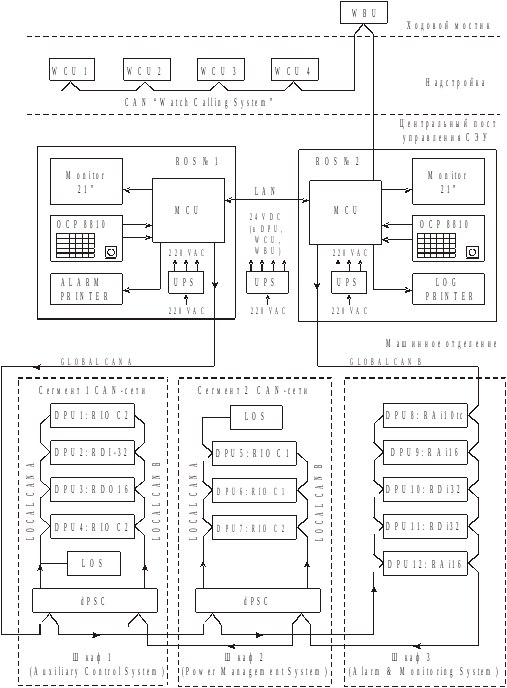
Рис. 1. Схема МПСУ
«Data
chief—С20«
Блок
MCU
по комплектации аналогичен персональному
компьютеру (РС).
Панель
управления OCP
содержит клавиатуру, трекбол и элементы
сигнализации. Этот блок аналогичен
блоку OCP,
используемому в МПСУ «Data
chief-7/2000«.
Блок питания UPS
обеспечивает переменным питающим
напряжением 220 В (220 VAC)
блоки ROS.
При исчезновении входного питающего
напряжения переменного тока 220 В, он
преобразует постоянное напряжение
встроенного в него аккумулятора в
переменное 220 VAC,
обеспечивая, тем самым, бесперебойное
питание.
Для
обеспечения безвахтенного обслуживания
СЭУ система DC-С20
укомплектована блоками сигнализации
и вызова вахтенного (WCU),
расположенными в каютах механиков и
местах нахождения членов машинной
команды. Блок WCU
выполнен на основе жидкокристаллического
цифрового дисплея). Эти блоки, а также
блок аналогичного назначения, расположенный
на ходовом мостике (WВU)
объединены в отдельную локальную CAN
–сеть, подключенную к ROS
№2, образуя систему вызова вахтенного
– «Watch
Calling
System«.
Эта часть оборудования обеспечивает
функции СЦК.
Блоки
DPU
являются наиболее многочисленным
компонентом системы DC-С20.
Они являются управляющими ЭВМ,
непосредственно воспринимающими сигналы
датчиков, обрабатывающие их в соответствии
с заложенным в их программу алгоритмом
работы и формирующими выходные управляющие
воздействия. Имеется более 10 типов
блоков DPU,
каждый их которых специализирован под
конкретные типы входных и выходных
сигналов.
В
отличие от управляющих ЭВМ, использованных
в системах «Data
chief-7/2000«,
блоки DPU
не имеют собственной панели управления
и поэтому автономно функционировать
не могут, только в составе системы.
Общими отличительными особенностями
блоков DPU
являются:
-
отсутствие
органов настройки, обслуживаемых в
эксплуатации и сменных компонентов (в
эксплуатационных условиях блоки DPU
не ремонтируются); -
все
настроечные параметры изначально
записаны в модуль и могут быть изменены
только программным путем, через локальную
сеть; -
каждый
модуль DPU
имеет два порта для подключения к двум
независимым CAN-сетям,
а также дополнительный последовательный
интерфейс RS422
или RS485; -
состояние
модуля, входные и выходные сигналы,
режимы его работы индицируются
светодиодами (LED); -
обеспечивается
самодиагностика.
Блоки
DPU
объединены в систему и связаны с ROS
через CAN-сеть.
Для обеспечения надежности это подключение
реализовано в виде двух независимых
сетей (рис. 1) – GLOBAL
CAN
A,
замыкающейся на ROS
№1, и GLOBAL
CAN
B,
замыкающейся на ROS
№2. Каждый блок DPU
в своем программном обеспечении содержит
адрес и другую информацию, необходимую
для его идентификации. Когда блок DPU
физически подключается к сети, например,
взамен отказавшего, программа, работающая
в ROS,
по этой информации автоматически его
распознает. таким
образом, от обслуживающего персонала
не требуется никаких специальных
действий по вводу блока в действие,
достаточно лишь указать его номер.
Данный принцип в компьютерной технике
именуется «plug
and
play»
– подключай и работай. Питание блоков
DPU,
а также WCU
и WВU
осуществляется напряжением 24 В постоянного
тока (24 VDC)
от блока бесперебойного питания UPS
(рис. 1).
Через
CAN-сеть
станции ROS
получают информацию от блоков DPU,
передают в них команды управления
оборудованием, осуществляют изменение
их настроечных параметров, калибровку
и т.д. Программное обеспечение станции
ROS
контролирует связь через сеть с каждым
DPU
и при ее потере формирует сообщение о
неисправности.
Каждый
блок DPU
также имеет средства самоконтроля –
контролируется температура внутри
блока, работоспособность его запоминающего
устройства, состояние CAN-сети.
Кроме этого, каждый блок DPU
имеет так называемый «сторожевой
таймер»
— «Watch
Dog
Timer
(WDT)».
Это отдельное устройство в составе DPU,
контролирующее его общую работоспособность.
Пока управляющая программа в блоке DPU
работает правильно, она периодически
подает импульсы в WDT,
удерживающие его в исходном состоянии.
Если в управляющей программе DPU
произошел сбой, эти импульсы прекращают
поступать в WDT
и по прошествии определенного времени
WDT
срабатывает. При этом он формирует
сигнал сброса (reset),
останавливающий микроЭВМ блока DPU.
Это предотвращает появление и развитие
опасных ситуаций в системе управления,
где используется блок DPU.
Срабатывание WDT
сигнализируется светодиодом.
В
условиях судна блоки DPU
сгруппированы в шкафах по функциональному
признаку, обеспечивая в составе DC—C20
функции ряда локальных систем автоматизации
(см. рис. 1):
-
система
автоматизации вспомогательного
оборудования (Auxiliary
Control
System)
– насосы, компрессоры и др.; -
система
автоматизации судовой электростанции
(Power
Management
System)
– дизель-генераторы, валогенератор; -
система
централизованного контроля (Alarm
and
Monitoring
System)
и др.
Для
реализации функций этих систем
используются соответствующие типы
блоков DPU.
Ряд таких подсистем могут функционировать
и самостоятельно, без связи со станцией
ROS.
В этом случае они дополнительно
комплектуются местными станциями
управления (LOS)
(рис. 1).
С
помощью станций LOS,
которые при наличии ROS
рассматриваются как дополнительные,
резервные панели управления, могут
выполняться операции по управлению
оборудованием, наблюдению за процессами,
настройке параметров блоков DPU,
имитации их входных и выходных сигналов,
проверке диагностических сообщений и
др.
Блоки
DPU,
сгруппированные по видам подсистем
автоматизации, подключаются к общей
CAN-сети
(глобальной – Global)
не напрямую, а через блоки расширения
типа dpsc
(см. рис. 1). Тем самым в пределах подсистемы,
шкафа образуется местная, локальная
CAN-сеть
(Local
CAN),
являющаяся сегментом общей сети.
Необходимо отметить, что на рис. 1
представлены лишь типы блоков DPU,
которыми комплектуются подсистемы.
Конкретное же их количество определяется
объемом автоматизации конкретного
судна и значительно превышает
представленное на рис. 1.
Ниже
дана краткая характеристика некоторых
типов блоков DPU:
-
RAI-16
(Remote
Analogue
Input)
– блок ввода 16 аналоговых сигналов; -
RDI-32
(Remote
Digital
Input)
– блок ввода 32 дискретных входных
сигналов от контактных датчиков; -
RDI-32A
(Remote
Digital
Input)
– блок ввода 32 дискретных сигналов
переменного тока или постоянного тока
24 В; -
RAI-10tc
(Remote
Analogue
Input)
– блок ввода 10 сигналов от термопар; -
RDO-16
(Remote
Digital
Output)
– блок вывода 16 дискретных, формируемых
с помощью реле сигналов, имеется выход
импульсного сигнала; -
RAO-8
(Remote
Analogue
Output)
– блок вывода 8 аналоговых сигналов в
диапазоне 10
В или 0…20 мА; -
RIO-C1
(Remote
Input/Output)
– многоцелевой комбинированный блок
ввода/вывода входных/выходных сигналов,
в том числе: 6 выходных дискретных
сигналов; 2 входных импульсных сигнала;
2 входных сигнала 0…30 VAC
и один входной сигнал 0…1 А переменного
тока; 4 аналоговых или дискретных входных
сигнала и др.; -
RIO—C2
(Remote
Input/Output)
– комбинированный блок ввода 8 дискретных
и вывода 8 дискретных сигналов.
Блоки
типов RAI
и RDI
используются в основном для реализации
функций СЦК (рис. 1).
Для
управления вспомогательными механизмами
и дизель-генераторами используются
блоки типов RIO—C2
и RIO—C1
(рис. 1). В частности, блок RIO—C2
применяется для управления насосами,
клапанами, пуска, остановки и защиты
дизель-генератора и т.д. Через блок
RIO—C1
обеспечивается управление автоматическими
выключателями генераторов, синхронизация
подключаемого генератора, он способен
выполнять функции ПИД-регулятора и т.д.
Алгоритмы
обработки сигналов в блоках DPU
реализованы в виде программ, работающих
в этих блоках, и определяются их
функциональным назначением. Так,
например, обработка поступающих от
датчиков аналоговых сигналов в блоке
RAI-16
предусматривает выполнение следующих
операций:
-
преобразование
в АЦП аналогового сигнала в 16-разрядный
цифровой код; -
фильтрацию этого
сигнала в фильтре нижних частот второго
порядка (Баттерворта), фильтр реализован
в виде расчетной формулы; -
преобразование
цифрового сигнала к диапазону входного
параметра, выраженному в физических
единицах или в процентах; -
расчет скорости
изменения параметра; -
сравнение
измеренного значения с четырьмя
заданными значениями уставок на
сигнализацию: LL
(Low
Low)
– предельно низкое, L
(Low)
– низкое, H
(High)
– высокое, HH
(High
High)
– предельно высокое и формирование
временных задержек сигнализации; -
формирование и
ведение хронологической записи сигналов
тревоги; -
проверка
достоверности входного сигнала с
формированием сообщения об ошибке,
если он более чем на 5 % вышел за верхний
или нижний предел диапазона, в котором
должен находиться; -
и др.
Фирмой
Kongsberg
разработана также МПСУ «Auto
chief–C20«,
по сравнению с МПСУ «Auto
chief–4»
являющаяся новым поколением системы
дистанционного автоматизированного
управления (ДАУ) главным судовым
двигателем (МОД). В ней реализованы те
же основные принципы построения, что и
в системе DC—C20
– блоки DPU,
CAN-сеть
и др.
Соседние файлы в предмете [НЕСОРТИРОВАННОЕ]
- #
- #
- #
- #
- #
- #
- #
- #
- #
- #
- #

Геннадий Гоголев
Эксплуатация современных судовых дизельных установок
![]()
Геннадий Гоголев
Эксплуатация современных судовых дизельных установок
Геннадий Вениаминович Гоголев
Эксплуатация современных судовых дизельных установок
Рецензенты:
В. М. Величко – механик I разряда ДВС, суперинтендант компании Primerose Shipping Co.Ltd.
Е. А. Трофимов – механик I разряда ДВС.
В книге изложены особенности эксплуатации современных судовых дизельных энергетических установок. Рассмотрены характеристики пропульсивного комплекса, конструкция и эксплуатация ВРШ, области допустимых эксплуатационных режимов главных двигателей, особенности их технического использования в особых условиях, эксплуатация современных двигателей с электронным управлением,
Описаны современные технические средства и системы наддува для эффективной эксплуатации ГД на малых и экономичных ходах, влияние внешних и эксплуатационных условий, особенности технического использования ГД, в том числе и в особых условиях.
Даны сведения о современных валогенераторных установках малооборотных ГД типа PTO/RCF и PTO/CFE, позволяющих обеспечивать электроснабжение судна на режимах частичных нагрузок, об особенностях использования в судовых дизельных установках низкосернистых топлив типа ULSFO (0,10 % S), VLSFO (0,50 % S).
Подробно рассмотрены системы автоматического управления современными ГД (WECS-9520, Norcontrol AutoСhief III, UNIC) и пропульсивным комплексом (AutoChief C20, AutoChief® 600, DENIS-9520, BERG Propulsion), описано оборудование, типовые неисправности, методы контроля технического состояния и диагностирования элементов судовых дизельных установок.
Рассмотрены конструкции современных гидропневматических электронных регуляторов частоты вращения дизелей, методы их настройки, типовые неисправности. Обобщен зарубежный опыт по созданию, компановке и эксплуатации автоматических систем управления пропульсивным комплексом.
Предназначено для специалистов, эксплуатирующих судовые дизельные установки, а также полезна учащимся морских учебных заведений.
Предисловие
Дизельные энергетические установки, отличающиеся высокой экономичностью, надежностью и управляемостью, наиболее широко используются в современных судовых пропульсивных комплексах (ПК).
СДЭУ эксплуатируются при различных внешних, эксплуатационных условиях в широком диапазоне режимных параметров. Эффективная и безопасная эксплуатация обеспечивается во многом за счет технически грамотного обслуживания оборудования СДЭУ, что позволяет избежать необоснованную работу судового энергетического оборудования при чрезмерных механических и тепловых нагрузках.
Конфигурации допустимых областей эксплуатационных режимов современных двигателей, работающих на винты как фиксированного, так и регулируемого шагов, с валогенератором (ВГ) и без него, достаточно разнообразны.
Современные валогенераторные установки малооборотных ГД позволяют обеспечивать электроснабжение судна и на основных эксплуатационных, и на режимах частичных нагрузок. Используются ВГ с постоянным передаточным числом (PTO/GCR), с постоянной частотой вращения (PTO/RCF), с постоянной электрической частотой (PTO/CFE).
Современные технические средства и системы наддува, позволяют безопасно и достаточно эффективно эксплуатировать ГД на малых и экономичных ходах за счет байпасирования ГТН (Exhaust Gas Bypass, сокращенно EGB), регулируемого поворотного соплового аппарата турбины, сокращенно VTA; отключения ГТН (TC Cut-Out System).
Эксплуатация ГД при пуске, разгоне, реверсировании, на аварийных режимах, а также в ледовых, штормовых и других особых условиях имеет свои особенности и требует особого внимания. Безопасная эксплуатация во время шторма предотвращает аварии и крушения судов, которые, к сожалению, еще происходят. Сравнительно недавние крушения таких судов как лайнер «Эстония», танкеры «Эрика», «Престиж», контейнеровоз «Мол Комфорт», а также произошедшие уже в двадцатые годы потери танкера «Китус», грузовых судов «Unit K» и «Хейва Мару», судна ро-ро «Daha», рыболовецкого судна «Восток», сухогруза «Luno» и др. С ноября 2020 года в штормовых условиях произошло 6 инцидентов с потерей груза. Ежегодно в море теряется порядка 1,5 тысяч контейнеров.
Изложены сведения о современных измерительных приборах, комплексах и методах диагностики. Характерный вид индикаторных диаграмм при различных неисправностях позволяет быстро идентифицировать последние. Использование современных высокотехнологичных конструкций и систем управления ВРШ обеспечивают необходимую повышенную надежность и безопасность мореплавания.
Реализация тех или иных режимов работы связана с техническим использованием дистанционных автоматических систем управления. Установившиеся, а тем более неустановившиеся режимы работы СДУ, обеспечиваются автоматизированными системами управления главным двигателем и движением судна, знания о структуре, составе, регулировочных настройках и возможных неисправностях которых необходимы для успешной безаварийной эксплуатации судовых ДЭУ.
Актуальной проблемой остается получение более полных знаний по особенностям работы и надежной эксплуатации дизельных двигателей и систем автоматического управления современными пропульсивными установками. Достаточно подробное рассмотрение вопросов, касающихся конструкции, обслуживания, настройки, поиска неисправностей как новых, так и уже не новых систем регулирования частоты вращения дизелей будет полезно эксплуатирующим их специалистам.
Особое внимание уделено современным высокотехнологичным двигателям с электронным управлением Wärtsilä типа Sulzer RT-flex с системой управления WECS-9520 и двигателям международной компании «MAN Diesel & Turbo» типов ME, ME-C, ME-B, CR. Изложены сведения по системам управления движением AutoChief C20, AutoChief® 600, DENIS-9520, Alphatronic 2000.
Актуальной проблемой в настоящих экономических условиях (необходимость более широкого освоения северного морского пути) является обеспечение успешной и безопасной эксплуатации современных высокоэкономичных ГД в условиях ледового плавания (работа с “облегченым” винтом, арктический перепуск наддувочного воздуха, подогрев охлаждающей воды, рекомендации по пуску и нагружению, расчет времени предварительного подогрева).
Актуальным и необходимым является рассмотрение свойств и особенностей применения низкосернистых топлив ULSFO (0,10 % S), VLSFO (0,50 % S), процедуры проверки их совместимости, обеспечения смазывающей способности и вопросы подготовки и модернизации топливных систем.
Подробное рассмотрение принципов действия, функций, конструктивных особенностей различных гидравлических и электронных регуляторов частоты вращения, методов их настройки и типовых неисправностей способствует их более эффективному использованию.
Рассмотрено влияние гидрометеорологических условий плавания и методы приведения мощности и расхода топлива к стандартным условиям согласно
ГОСТ Р 52517–2005 (ИСО 3046–1:2002).
Автор настоящей книги доцент, к.т.н., имеющий опыт работы на различных судах и длительный опыт преподавательской работы в морских высших учебных заведениях, при написании книги использовал значительное количество технической литературы и документации, прибегал к консультациям специалистов, непосредственно занимающихся эксплуатацией современных диэельных установок. Автор выражает особую благодарность суперинтендантам Величко В. М. (компания Primerose Shipping Co.Ltd.), Оверко В. С., Тимченко Р. И. (компания Laskaridis Shipping Co.Ltd.), старшему механику Трофимову Е. А., капитану дальнего плавания Величко А. В. и инженеру Слободянюку В. Л. за оказанную помощь, высказанные рекомендации и замечания.
В условиях непрерывного сокращения объема часов, выделяемых на изучение ключевых дисциплин, необходимых для успешного проектирования и эксплуатации судовых энергоустановок, как, впрочем, и других технических объектов, необходимо наличие доступной, современной технической литературы (как в печатной, так и электронной форме), описывающей особенности эксплуатации как широко известного, так и нового оборудования.
Технологическое отставание в двигателестроении можно ликвидировать на основе развития собственных разработок и тщательного изучения и анализа зарубежного опыта и достижений. Подробная информация по современным зарубежным разработкам будет полезна инженерам создателям отечественной техники.
В монографии не рассматриваются типовые отказы и вопросы эксплуатации систем СДУ, так как они достаточно изложены в предыдущей книге [9] и другой известной литературе.
Китайское “экономическое чудо” основано на творческой переработке передового опыта, технологий, создании собственного интеллектуального потенциала нации за счет действительно эффективной системы образования на всех уровнях. Те, кто были в Китае, наверное, обратили внимание на отсутствие детей на улицах. Они с утра до 8 часов вечера в школах. В результате мы с удивлением наблюдаем непривычно трудолюбивых, упорных китайских студентов и специалистов, которые, кстати, в отличие от многих других уверены, что у них будет работа по специальности.
Повсеместное увлечение наспех организованными дистанционными методами обучения с сокращенным объемом, с целью экономии средств и затрат на образование, не заменят работу с опытными преподавателями и современной учебной технической литературой, которой очень мало.
Целью изложенных материалов и рекомендаций, является прежде всего помощь судовым механикам и выпускникам морских учебных заведений. В издании рассмотрен ряд специальных, достаточно узких вопросов, связанных с эксплуа – тацией и дистанционным автоматическим управлением судовых дизельных энергоустановок в обычных и особых условиях. Книга полезна учащимся морских учебных заведений для приобретения современных профессиональных знаний.
Список сокращений
АЭРН – автоматический электронный регулятор нагрузки;
АПС – аварийно-предупредительная сигнализация;
ВГ – валогенератор;
ВДГ – вспомогательный дизель-генератор;
ВМТ – верхняя мертвая точка;
ВН вспомогательный нагнетатель
ВПУ – валоповоротное устройство;
ВРК – винторулевая колонка
ВРЧВ – всережимный регулятор частоты вращения
ВРШ – винт регулируемого шага;
ВФШ – винт фиксированного шага
ГОС – гибкая обратная связь шага;
ГД – главный двигатель;
ГТК – Газотурбокомпрессор
ДАУ – дистанционное автоматическое управление;
ECS – системауправления двигателем;
ЖОС – жесткая обратная связь;
МИШ – механизм изменения шага;
МО – машинное отделение
ПК – пропульсивный комплекс
ПКВ – угол поворота коленчатого вала;
ПТЭ – правила технической эксплуатации;
РПУ – реверсивно-пусковое устройство;
САУ – системами автоматического управления
СДЭУ – судовая энергетическая установка;
СОД – среднеоборотный дизель;
СТС – судовое техническое средство;
МОД – малооборотный двигатель;
ТИ – техническое использование;
ТИ – техническое использование;
ТНВД – топливный насос высокого давления;
ТО – техническое обслуживание
ЦПУ – центральный пост управления;
ЧЭ – чувствительный элемент
Раздел 1. Пропульсивный комплекс сдэу и его эксплуатация
1.1. Состав и типы судовых дизельных энергетических установок
В состав СЭУ входят главная энергетическая установка (ГЭУ) и вспомогательные установки. Главная (пропульсивная) энергетическая установка (пропульсивный комплекс) обеспечивает движение судна. Главные энергетические установки дизельных судов классифицируются по следующим признакам [1]:
– по типу главных двигателей (МОД, СОД, ВОД и комбинированные (чаще всего это дизель-газотурбинные установки).
– по типу передачи мощности на движитель (прямая непосредственная передача на ГВ, механическая, электрическая, гидравлическая и комбинированные передачи).
– по типу движителя (гребные винты фиксированного шага, гребные винты регулируемого шага, соосные винты противоположного вращения, винторулевые колонки с механической и электрической передачей мощности на винт, крыльчатые и водометные движители).
– по способу обеспечения реверса (с реверсивным ГД, с нереверсивным ГД и реверсивной муфтой, с нереверсивным ГД и ВРШ, с винторулевыми колонками.
По степени автоматизации, способу управления и обслуживания СДЭУ бывают:
1. Неавтоматизированные и частично автоматизированные с местным постом управления и постоянной вахтой в МО.
2. Автоматизированные СДЭУ с ДАУ без постоянного присутствия обслуживающего персонала в МО. Несение вахты осуществляется одним механиком в ЦПУ (степень автоматизации А2, А3).
3. Автоматизированные СДЭУ с ДАУ без постоянного присутствия обслуживающего персонала в МО и ЦПУ (степень автоматизации А1).
ДЭУ с прямой передачей на мощности на винт (ВФШ) являются наиболее распространенными. ГД при этом может быть соединен с гребным валом через жесткую фланцевую муфту, через разобщительную муфту, через реверсивную муфту или через ВРШ (с валогенератором и без него).
Установки с ВФШ обеспечивают достаточно высокие значения пропульсивного КПД, надежны и устойчивы в работе. Они применяются на крупнотоннажных судах Двухвальные СДЭУ применяются на паромах, буксирах. пассажирских и речных судах. Трехвальные установки примененияются редко.
Широко применяются дизель-редукторные установки (ДРУ). Существуют схемы ДРУ с отбором мощности и с различными исполнениями редукторных передач [1,2].
На судах относительно небольшой мощности специального назначения находят широкое применение винторулевые колонки (ВРК) объединяющие движительный и рулевой комплекс в одном агрегате.
Они значительно расширяют эксплуатационные возможности и маневренные характеристики ПК.
Производителями главных ВРК являются зарубежные фирмы «Aquamaster», «Steerprop Ltd», «Schottel Gmbh», «Niigata» и др. В России ВРК выпускает завод
«Сапфир» в Большом Камне и НПО «Винт» [3]. Главные винторулевые колонки (ГВРК) выпускаются с одиночными и соосными винтами противоположного вращения и гребными винтами в направляющих насадках. ССК «Звезда» освоила выпуск судов снабженцев ледового класса.
1.2. Характеристики пропульсивного комплекса
Пропульсивный (propulsive – движущий) комплекс является системой взаимодействующих элементов, обеспечивающих движение, маневрирование и остановку судна с обеспечением высокой степени надежности в различных эксплуатационных условиях. Дизельная энергетическая установка входит в состав ПК и режимы ее работы будут во многом определяться характеристиками конкретного ПК
В состав ПК входят: главный двигатель или двигатели (если их несколько), передача (редуктор, соединительные муфты, валопровод), гребной винт (ГВ), корпус судна.
На транспортных судах чаще всего применяют ПК с малооборотными двухтактными двигателями (МОД) и прямой передачей мощности на гребной винт. Используются СДУ как с прямой передачей, так и с ВРШ. Применение дизель-редукторных установок (ДРУ) с среднеоборотными двигателями (СОД) позволяет сократить размеры МО по высоте и облегчить отбор мощности на ВГ. Находят применение различные компоновочные и схемные решения [1,2,4,28].
Совмещение характеристик корпуса и винта определяет необходимую мощность ГД. Рассмотрим взаимодействие и условия работы элементов ПК.
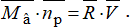
Взаимодействие гребного с водой и корпусом судна характеризуется создаваемым винтом упором P, вращающим моментом поглощаемым винтом, частотой вращения винта np, скоростью воды, поступающей на лопасти Va, (из-за наличия попутного потока она меньше скорости движения судна V), поступью гребного винта hp и в конечном итоге к.п.д. винта ηp.
Схема судового пропульсивного комплекса и описание взаимодействия его элементов приведены в источнике [2].
Гребной винт встречает воду не со скоростью движения судна V, а со скоростью Va уменьшенной на величину скорости попутного потока, который вызван трением воды вдоль сторон корпуса и увеличивает упор винта.
Va = V–Vп
Наличие попутного потока улучшает работу ПК, его влияние учитывается коэффициентом попутного потока.

Кроме того, в процессе работы ГВ засасывает воду из под кормы, отбрасывая ее назад и уменьшая давление воды на кормовую часть. Возникающая сила засасывания, отнесенная к упору винта, называется коэффициентом засасывания.
Обводы, размеры и состояние корпуса и кормовой части, расположение и режимы нагрузки гребного винта влияют на пропульсивные качества и оцениваются коэффициентом влияния корпуса.

где ω – коэффициент попутного потока, ω = 0,2…0,45;
t – коэффициент засасывания, t = 0,12…0,3;
i – коэффициент, учитывающий неравномерность поля скоростей в диске винта, i = 0,95…1,03.
Буксировочная мощность расходуется на преодоление сопротивления движению судна.
Nб = R ∙ V = Pе ∙ V
Осевая скорость винта относительно воды Vp незначительно отличается от скорости Va.
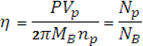
Пропульсивный коэффициент – это отношение буксировочной мощности к мощности подводимой к винту NB.
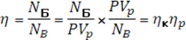
Пропульсивный коэффициент характеризует гидромеханические потери на ГВ при его взаимодействии с корпусом.
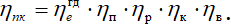
Помимо этих потерь следует учитывать потери в редукторной передаче ηn (при ее наличии), валопроводе ηB и потери в ГД.
Тогда К. П. Д. пропульсивного комплекса представляется в виде:
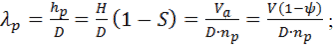
Поступь винта hp – это путь, пройденный винтом в воде за один оборот. Относительная поступь – это поступь, отнесенная к диаметру винта D.
Если бы гребной винт вращался в твердой среде, как штопор в пробке, то за один оборот он бы прошел расстояние, равное шагу винта H без скольжения.
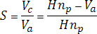
Скольжение S – безразмерная величина, определяемая как отношение скорости скольжения Vc = (H × np – Va) к осевой скорости винта в «твердой среде», равной H × np
В реальных условиях скольжение винта относительно воды является условием создания упора винта. Винт отбрасывает воду назад и создает упор. Без скольжения не будет и упора винта.
Упор ГВ зависит прямо пропорционально от массы и скорости отбрасываемой воды, а потери энергии с отбрасываемой частью воды пропорциональны произведению массы на скорость воды во второй степени, поэтому КПД винта будет увеличиваться при увеличении диаметра D и снижении частоты вращения винта np. Масса отбрасываемой воды будет возрастать при увеличении диаметра ГВ, а обороты винта np при этом можно снизить. КПД винта зависит от относительной поступи, а также от обводов корпуса и имеет для ВФШ ярко выраженное оптимальное значение при определенном λp.
На рисунке 1.1. приведены кривые действия геометрически подобных винтов фиксированного и регулируемого шага [2].
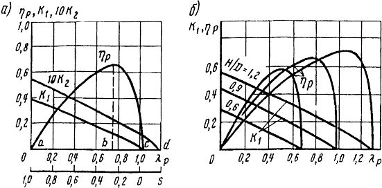
Рис 1.1. Кривые действия гребных винтов:
а) – ВФШ; б) – ВРШ [2].
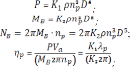
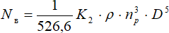
Соответствующие зависимости для упора, момента, мощности и КПД винта при упрощающем допущениях, что MB~n2p, NB~n3p выражаются формулами:
Из анализа зависимостей КПД на рисунке 1.1а и 1.1б видно, что ВРШ обеспечивает работу с высоким КПД в широком диапазоне режимов. Изменения величин λp и S происходит при значительных воздействиях на сопротивление движению судна (разгон, торможение, работа во льдах). ВРШ широко применяются в установках, где часто меняются режимы работы.
Пропульсивный комплекс должен обеспечить не только заданную спецификационную скорость движения судна за счет создания тяги Pe и подведение к винту мощности NB, но и обеспечить надежную работу в определенном диапазоне скоростей и частот вращения.
Для анализа совместной работы гребного винта, корпуса судна и ГД используют ходовые или паспортные диаграммы судна. Они представляются в виде зависимостей R = f (V) и NB f (V).
Паспортную (ходовую) диаграмму судна первоначально представляют в виде зависимостей сопротивления движению R от скорости судна V при различных условиях плавания и при различных постоянных частотах вращения гребного винта np.
R(PB) = f (V, np, условия плавания)
Затем эту паспортную диаграмму можно перестроить в диаграмму зависимости мощности, потребляемой гребным винтом, от возможной скорости движения судна при различных сопротивлениях движению судна по условиям плавания или зависимости от значений относительных поступей винта λp при различных частотах его вращения np.
NB = f (V, np, λp).
Для построения кривых, представленных на рис. 1.2, можно использовать следующие уравнения.
Мощность буксировки судна с заданной скоростью на свободном ходу:
NR = R ∙ V.
Мощность, потребляемая гребным винтом:
NB = MB ∙ ωB,
где MB – крутящий момент, потребляемый гребным винтом;
ωB – угловая скорость вращения гребного винта, 1/с.
Зная экспериментальные значения коэффициентов упора K1 и момента K2 для гребного винта выбранной серии, можно определить зависимости упора винта и потребляемой винтом мощности от скорости судна, по приведённым выше формулам [2] или по формулам [5].

где KC = K1(1 – t)i – коэффициент тяги.
Паспортные диаграммы (графики Pe = f(np,V) и Nb = f'(np, V)) позволяют определить для установившихся режимов судна взаимосвязи между мощностью, подводимой к винту, частотой вращения винта и скоростью судна.
Эти диаграммы потом уточняются по результатам ходовых испытаний.
Общая конфигурация последней паспортной диаграммы с учетом ограничения по мощности ГД представлена на рисунке 1.2.
Если перенести кривые мощности, потребляемой винтом 2 в координаты NeГД = f(nГД), учитывая, что частоты ГВ и ГД равны или связаны через величину передаточного числа редуктора, то получим широко распространенную диаграмму скоростной характеристики двигателя Ne = f(n), которая является паспортной диаграммой пропульсивного комплекса «корпус – движитель – двигатель».
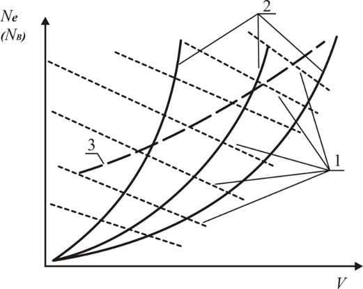
Рис. 1.2. Паспортная диаграмма судна с пропульсивной установкой с ВРШ:
1 – n=const; 2 – λp= const; 3 – ограничительная характеристика по эффективной мощности.
Согласование характеристик «корпус-винт» с характеристиками двигателя графически представлено на рисунках 1.3 [5]. Нанося предельные характеристики двигателя на характеристики комплекса «корпус-винт», получим в левой части рисунка 1.8 паспортную диаграмму пропульсивного комплекса «корпус-движитель—двигатель».
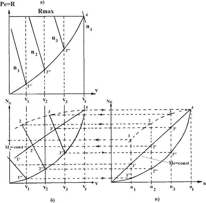
Рис. 1.3. Характеристики и паспортная диаграмма пропульсивного комплекса [5]
Для анализа работы ГД по винтовой характеристике наносится кривая потребляемой винтом мощности. Для этого точки 1”– 2”-3”-4” на кривой зависимости потребляемой винтом мощности от скорости судна переносятся на правый график при тех же частотах вращения двигателя и, соединив их плавной кривой, получим винтовую характеристику двигателя.
Динамические качества ПК будут зависеть от ряда факторов. Определим факторы, влияющие на скорость движения судна.
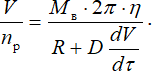
Буксировочная мощность Nб зависит от мощности, подводимой к винту и пропульсивного коэффициента
Nб = R∙V = NB∙η = 2π∙MB∙np∙η.
Отсюда скорость движения судна
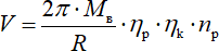
Буксировочная мощность Nб зависит от мощности, подводимой к винту и пропульсивного коэффициента
Nб = R∙V = NB∙η = 2π∙MB∙np∙η.
Отсюда скорость движения судна

На стационарных режимах работы при неизменных внешних факторах скорость судна будет пропорциональна частоте вращения винта.
При постоянстве пропульсивного КПД η будет соблюдаться равенство относительных величин
Это значит, что в относительных координатах характеристика винта  и корпуса
  будут одинаковыми. Таким образом, на стационарных режимах соблюдается условие автомодельности характеристик сопротивления корпуса и винта. Это позволяет моделировать эксплуатационные режимы СЭУ и судна.
При переходных режимах (разгон, торможение, реверсирование, работа на волнении) будут дополнительно возникать инерционные силы и моменты движущихся масс
R’ = D(dV/dτ)
и вращающихся масс
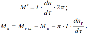
Тогда отношение скорости судна к частоте вращения винта выразится
Все величины, кроме водоизмещения, будут переменными. Инерционной составляющей линии валопровода I∙(dω/dτ) можно пренебречь.
Анализ зависимости отношения V/np показывает, что на участках ускоренного движения судна рост скорости судна будет отставать от роста частоты винта, а при торможении, наоборот, инерция массы судна D(dV/dτ) будет отрицательная и будет способствовать поддержанию скорости судна.
Кроме того, следует отметить, что изменение частоты вращения при изменении уставки регулятора также будет происходить неравномерно, особенно при пуске ГД и использовании регуляторов без функций ограничения по нагрузке и давлению наддува (типа UG-40) [6].
Забросы топливоподачи могут быть значительным, что ведет к повышенным термическим напряжениям. Если используются регуляторы, реализующие ограничительную характеристику (типа UG-40TL и электронные), то забросы топливоподачи будут значительно меньше.
От настройки изодромной связи зависит многое. В современных электронных регуляторах (DGU 8800) в память микропроцессора занесена вся необходимая информация о двигателе, включая и момент инерции вращающихся масс, что позволяет автоматически мгновенно вычислять реальный вращающий момент двигателя с учетом инерционной составляющей на любом режиме и автоматически изменять характеристики (настройки) изодромной связи регулятора, обеспечивающие оптимальную по расходу топлива и по износу динамику работы двигателя (см. пункт 6.2.3.5).
Динамические качества пропульсивной установки будут зависеть от соотношения влияния перечисленных факторов (величины крутящего момента, пропульсивного коэффициента, инерционной силы движущихся масс судна, заданий регулятора).
Дизельная энергетическая установка входит в состав ПК и режимы ее работы будут во многом определяться характеристиками конкретного ПК.
Модераторы: Breeze, Soarer
- Активные темы
- На страницу 1 2 3 4 5 След.
STRUJA 26 май 2010, 08:59 |
|
|
Доброго времени суток!! Очень нужен совет от тех кто работал с Kongsberg Auto Chief 20, вопрос в том как вводится адрес в модули этой системы??? |
Откуда: Регион 25 Репутация: 2 |

dmk 13 июн 2010, 06:48 |
|
|
STRUJA, по-моему у Конгсберга официальная позиция не предоставлять конечному пользователю такую возможность. El pueblo unido jamás será vencido! |
Откуда: Архангельск Должность: Электромеханик Тип судов: Оффшор: платформы Репутация: 1046 |

hlu386 27 июн 2010, 15:40 |
|
|
Фирмачи много чего не хотят. Но в центр океана сервис на вертолёте не прилетит Механик-танкерист |
Откуда: Novorossiysk / Russia Должность: Третий механик Тип судов: Нефтяные танкера Репутация: 154 |
 .
.

Karmor 06 сен 2010, 18:11 |
|
|
Не знаю, у меня в последнее время попадались поновее, Kongsberg Auto Chief 4. Но в обще, в самой этой системе Propulsion Control System, менялись на моей памяти только PCB для управления VIT-актуаторв новой модификации. Никаких адресов не вгонял, менял только уставки для VIT и FQS (fuel quality settings) на DENIS 6. Да и воевал немного уставкой вых. напряжения на блоках питания для SSU8100, AutoChief 4 and DGS 8800 (особенно здесь, и чаще всего!) — выходил аларм переодически Low control voltage на панелях. Прикольное, что потенциометр регулировки в таком недоступном месте, что только используя смятый наконечник для провода, можно подобраться без отключения питания. И то, не видя его а только «ощупью». В этом Kongsberg не доглядел конечно. И выставлял только 4.9 V, не более, но и не менее. Иначе опять повторяется всё. |
Откуда: Россия Должность: Электромеханик Тип судов: Контейнеровозы Репутация: 5 |

scat69 24 мар 2011, 18:48 |
|
|
У кого есть мануал к ECP? Sehd please |
Должность: Электромеханик Тип судов: Автомобилевозы Репутация: 0 |
Efin 23 май 2011, 01:43 |
|
|
Спрашивал в другой ветке,ещё здесь попробую: |
Efin корабельный секретарь
Откуда: WWW.leningrad.spb.ru Репутация: 40 |

dmk 23 май 2011, 05:50 |
||||||||||
Какого хрена по всем темам одно и тоже постить? Посетители Морехода, в своем большинстве, не читают какую-то одну тему, а просматривают почти все. Не надо думать, что Ваш вопрос не заметили. Вы зачем вообще в этой-то теме написали? Потому что тоже Конгсберг, г-н не ведущий? Разницу между Auto Chief и Data Chief знаете? Давайте скриншот в студию, название вашей IAS, а не только производителя, и порядок действий при переводе сигнализации. El pueblo unido jamás será vencido! |
Откуда: Архангельск Должность: Электромеханик Тип судов: Оффшор: платформы Репутация: 1046 |
Efin 23 май 2011, 14:01 |
|||||||||||||||||||
Зачем столько нервов на ровном месте?И без того работа нервная…Разницу не знаю,уважаемый профессор.Название моей системы K-Chief 500 Alarm and system monitoring.Переводится из ЦПУ путём нажатия на нужного инженера в окне выбора инженера,которого нужно поставить на вахту |
Efin корабельный секретарь
Откуда: WWW.leningrad.spb.ru Репутация: 40 |
dmk 23 май 2011, 15:02 |
|
|
Efin, будете обзываться профессором — буду ругаться. Скажите, на Watch Calling Mimic Display (2 of 2), напротив выбранного вахтенного меха, в столбце Qualifications, что написано? Должно быть Engine. El pueblo unido jamás será vencido! |
Откуда: Архангельск Должность: Электромеханик Тип судов: Оффшор: платформы Репутация: 1046 |

Efin 23 май 2011, 19:51 |
|
|
Должно быть Engine.[/quote] |
Efin корабельный секретарь
Откуда: WWW.leningrad.spb.ru Репутация: 40 |
dmk 24 май 2011, 09:05 |
||||||||||
Efin, это первая страница Watch Calling Mimic Display, то есть (1 of 2), и на ней напротив выбранного меха должно быть Е и Е в столбцах Qaual. и Duty. А что на второй? El pueblo unido jamás será vencido! |
Откуда: Архангельск Должность: Электромеханик Тип судов: Оффшор: платформы Репутация: 1046 |
Efin 25 май 2011, 00:02 |
||||||||||
|
Efin корабельный секретарь
Откуда: WWW.leningrad.spb.ru Репутация: 40 |
 Просмотров: 7912")
dmk 26 май 2011, 13:22 |
|
|
Efin, на второй странице, в левой части, напротив BRIDGE, в столбце Qualifications у вас выбрано None. El pueblo unido jamás será vencido! |
Откуда: Архангельск Должность: Электромеханик Тип судов: Оффшор: платформы Репутация: 1046 |
|
|
|
вопрос в том как вводится адрес в модули этой системы? |
Откуда: Latvija, Riga Должность: Второй механик Тип судов: Газовозы Репутация: 5 |

Efin 27 май 2011, 13:46 |
||||||||||
Пробывал-таже проблема |
Efin корабельный секретарь
Откуда: WWW.leningrad.spb.ru Репутация: 40 |
dmk 27 май 2011, 20:48 |
|
|
Efin El pueblo unido jamás será vencido! |
Откуда: Архангельск Должность: Электромеханик Тип судов: Оффшор: платформы Репутация: 1046 |
Efin 28 май 2011, 00:56 |
||||||||||
Вот это мы делаем очень часто на переходе ,когда уходим из машины на ночь.Да,похоже проблема гораздо глубже.Но вам ,DMK,все равно спасибо за участие.Будем трясти сам великий конгсберг,мать его… |
Efin корабельный секретарь
Откуда: WWW.leningrad.spb.ru Репутация: 40 |
|
||||||||||
Стесняюсь за банальность, но все-же, вы при переводе вахты на каюту механика активируете функцию bridge watch или нет? Если нет, то мои вам сожаления, если-да, то , описывайте проблемму и шлите масагу в техникал департмент. Они запросят мэйкера о возможной проблемме. Мэйкер пораскинет мозгами и, скорее всего, пришлет вам почтой файл, который надо будет перезаписать в компьютере AMS. Приложат и инструкцию как это сделать. |
Откуда: Nakhodka Должность: Электромеханик Тип судов: Нефтяные танкера Репутация: 125 |
Efin 28 май 2011, 17:48 |
|||||||||||||||||||
Когда на переходе -активируем,когда в порту-просто ставим нужного меха.И в том и в другом случаях ловим палубные алармы в каюте.То есть хотите сказать,что конгсберг может прислать рекомендации бесплатно?Тогда будем пробывать… |
Efin корабельный секретарь
Откуда: WWW.leningrad.spb.ru Репутация: 40 |
|
|
|
Возвращаясь к началу… Если нужен пароль для изменения параметров настройки, то при Ну и что, что я на работу опаздываю, зато ухожу с нее раньше. |
Откуда: Vladivostok Должность: Электромеханик Тип судов: Контейнеровозы Репутация: 187 |

|
|
|
подскажите пожалуйста где найти описания Norcontrol AutoChief, на руском языке |
Должность: Электромеханик Тип судов: Балкеры Репутация: 0 |
|
|
|
В машине и на мосту стоит по компу MCU 8625. Машинный иногда перегружается, потом требует поднастройки. На мосту висит на стадии загрузки ПО. Что там за ПО? Компики то по виду древние, типа 386-х пней. Где можно нарыть документашку на компы и ПО, хоть на английском? |
Откуда: Mariupol, UA Должность: Электромеханик Тип судов: Контейнеровозы Репутация: 280 |

Scorik 09 янв 2015, 20:54 |
|
|
Кто нибудь может подсказать, как правильно перегрузить компы ROS Norcontrol (Kongsberg) AutoChief ?? |
Должность: Электромеханик Тип судов: Газовозы Репутация: 9 |
|
||||||||||
( точно не помню описание) вводишь пароль потом заходишь в меню-там будет ros1 ros2 жмёшь стоп ros1 потом опять старт…и ros 2 потом аналогично. не останавливай обе станции на ходу. в порту можно-но нежелательно. а лучше и проще…перезапускай комп Alt +f4 и жми перезагрузить.после рестарта компа-система автоматом запустится. |
Должность: Электромеханик Тип судов: Балкеры Репутация: 48 |

|
||||||||||
Нажимаешь на OCP кнопку (operating control console) (это клавиатура ROS-remote operation station) System info display, открывается меню. В этом меню находишь позицию Start Service Console, заходим, выбираешь станцию которую хотим перезагрузить (левое верхние окно, у меня их 5) и нажимаем Stop Station. После на выбранной станции видим что программа остановилась, скорей всего выйдет сигнал CAN NETWORKING A AND B Alarm (у меня выходит). И в этомже меню нажимаем Start Station. Перезагрузка произошла.Удачи. |
Должность: Электромеханик Тип судов: Нефтяные танкера Репутация: 12 |
Code 15 янв 2015, 00:25 |
||||||||||
|
Code действительный тайный советник
Репутация: 904 |
 Поскольку все крутится под виндой полный перезапуск необходимость ибо такова ось.
Egoriy 15 янв 2015, 00:40 |
|
|
386-й — это не пень, а пень — это не 386-й! Помню, в 1994, купил практически, последний, перед ПНЁМ, 386-DX4-100, настольная машинка… По сути — г—- полное, диск на 850 мег. Но, тем не менее, какое то время, работал (о). Мужчина, в жизни, должен посадить дом, воспитать дерево, построить сына. |
Откуда: Находка, пыль да водка! Должность: Электромеханик Тип судов: Продуктовозы Репутация: 1500 |

|
|
|
В загрузке вроде отображается Pentium S 120 MHZ. Что-то в последнее время машинный комп стал часто перезагружаться. Уже воткнул в корпус каютный фан, не помогает. Похоже, деградация кремниевых элементов в чипах. Может электролиты, но с виду вроде дутых нет. Суперинтендант даёт отписки, что мол поставьте ещё один фан, замена компьютера будет очень дорого стоить. Месяц назад приходил представитель консберга по поводу неполадок ДГ. Взглянул на комп и сказал, что необходимо менять целиком. Я сперва думал, что хочет бабла скосить. Я надеялся, что дело в термопасте. Но замена не помогла (там её и не было, а стояла резиновая прокладка между процом и радиатором. В моём родном городе я бы спокойно нашёл замену такой матери. Но греки говорят, что в Пирее найти замену нереально. Ещё есть вариант, что гонит не мать, а БП, там ведь тоже электролиты. Кстати, жёсткий уже замнен на SSD. На мосту стоит такая же система, её юзает старпом только лишь для того, чтобы катать балласт. Я уже думал попробовать БП оттуда махнуть. Да и в крайнем случае можно и мамки махнуть, балласт старпом и в машине может покатать. Система работает из под ДОСа. Я так понимаю, что при замене идентичных матерей ничего переустанавливать не нужно. Сейчас система перезагружается пару раз в сутки. Стоим на рейде, завтра может пришлют техника из консберга, посмотрим, что он наколдует. |
Откуда: Mariupol, UA Должность: Электромеханик Тип судов: Контейнеровозы Репутация: 280 |
|
|
|
гугль по запросу MCU 8625 ничего толкового не даёт. Комп утром опять перегрузился. Я посмотрел параметры компа во время загрузки, там указана мать aopen ap5t http://www.motherboards.org/mobot/mothe … Open/AP5T/ Приходил вчера супер, сказал менять платы по очереди с мостиковым компом. Там всего три платы — видюха, сетевуха и плата соединения с контроллером. Но у меня больше подозрения на БП и мать, возможно проц, но врядле. |
Откуда: Mariupol, UA Должность: Электромеханик Тип судов: Контейнеровозы Репутация: 280 |
|
|
|
Накрылся AC4 Bridge Unit, не горит панель вообще, только среди Warning один индикатор FailSafe светится, управляем главным с ЦПУ. Траблешутинг отработал, все в порядке с напряжениями и прочим. Processor Card выдергивал с реверсографа (с переустановкой EEPROM и программного пакета конечно), ничего не изменилось. Через супера технишены прислали рекомендации те же, что и в мануале. Есть какие-то недокументированные возможности диагностики, может кому-то дельные советы мейкер присылал? Или все же EEPROMу кирдык? |
Должность: Электромеханик Тип судов: Химовозы Репутация: 1500 |

- Активные темы
- На страницу 1 2 3 4 5 След.
|
Кто сейчас на конференции Сейчас этот форум просматривают: нет зарегистрированных пользователей и гости: 7 |
||

Instruction manual AutoChief® C20
AA-0381-A i
AutoChief C20
Instruction Manual
MAN B&W MC Engines
Fixed Propeller installation

Instruction manual AutoChief® C20
ii AA-0381-A

Instruction manual AutoChief® C20
AA-0381-A iii
Revisions
Written by Checked by Approved by Rev. Date Sign. Date Sign. Date Sign.
A 07.12.04 ØT 04.01-05 DAM 06.01.05 SM B C D
Document history
Issue No. ECO No. Paragraph No. Paragraph Heading / Description of change
A AAE-000157 First Issue
The information contained in this document is subject to change without prior notice. Kongsberg Maritime AS shall not be liable for errors contained herein or for incidental or consequential damages in connection with the furnishing, performance, or use of this document. © 2003 Kongsberg Maritime AS. All rights reserved. No part of this work covered by the copyright hereon may be reproduced or otherwise copied without prior permission from Kongsberg Maritime AS.
Bekkajordet P.O.Box 1009N-3194 Horten,Norway
Kongsberg Maritime AS
Telephone: +47 33 03 20 00Telefax: +47 85 02 80 28www.kongsberg.com

Instruction manual AutoChief® C20
iv AA-0381-A
Table of contents
1 INTRODUCTION …………………………………………………………………………………………………………….1
2 FUNCTIONAL DESCRIPTION………………………………………………………………………………………..2
2.1 REMOTE CONTROL SYSTEM FUNCTIONAL DESCRIPTION……………………………………………………2 2.2 AUTOCHIEF® CONTROL PANEL (ACP)…………………………………………………………………………..5
2.2.1 Display………………………………………………………………………………………………………………….6 2.2.2 Cancel functions …………………………………………………………………………………………………….6 2.2.3 Alarm Acknowledge and in command functions………………………………………………………….7 2.2.4 Multifunctional knob……………………………………………………………………………………………….7
2.3 AUTOCHIEF® COMBINED LEVER AND TELEGRAPH UNIT (LTU) …………………………………………8 2.3.1 Emergency Stop ……………………………………………………………………………………………………..8 2.3.2 Command Transfer functions …………………………………………………………………………………..9 2.3.3 Sub-Telegraph functions………………………………………………………………………………………..10 2.3.4 Lever function………………………………………………………………………………………………………11
2.4 AUTOCHIEF® BRIDGE WING CONTROL UNIT BWU…………………………………………………………12 2.4.1 Emergency Stop ……………………………………………………………………………………………………12 2.4.2 Transfer functions…………………………………………………………………………………………………13 2.4.3 Safety functions…………………………………………………………………………………………………….14 2.4.4 Panel Dimming and lamp test…………………………………………………………………………………15 2.4.5 Lever function………………………………………………………………………………………………………16 2.4.6 Indicators…………………………………………………………………………………………………………….16
2.5 AUTOCHIEF® PUSHBUTTON TELEGRAPH (PBT)…………………………………………………………….17 2.5.1 Command Transfer functions …………………………………………………………………………………18 2.5.2 Sub-Telegraph functions………………………………………………………………………………………..19
2.6 AUTOCHIEF® START/STOP & SPEED-SET LEVER ……………………………………………………………20 2.7 INDICATION PANEL UNIT ……………………………………………………………………………………………21
2.7.1 Engine indicators………………………………………………………………………………………………….21 2.7.2 Auxiliary blower control………………………………………………………………………………………..23
2.8 EMERGENCY CONTROL EL. BOX STANDARD ………………………………………………………………….24 2.8.1 function and indicators………………………………………………………………………………………….24
2.9 DISTRIBUTED PROCESSING UNITS …………………………………………………………………………………25 2.9.1 General ……………………………………………………………………………………………………………….25 2.9.2 Main Engine Interface Unit (MEI) ………………………………………………………………………….27 2.9.3 Engine Safety Unit (ESU) ………………………………………………………………………………………28 2.9.4 Digital Governor Unit (DGU) ………………………………………………………………………………..29 2.9.5 Dual Process Segment Controller (dPSC)………………………………………………………………..30 2.9.6 RPMD Unit (RPMD) …………………………………………………………………………………………….31 2.9.7 Remote Analogue Input (RAi-16)…………………………………………………………………………….32 2.9.8 Remote Digital Input (RDi-32 and RDi-32a)…………………………………………………………….33 2.9.9 Remote Analogue Output (RAo-8) …………………………………………………………………………..33 2.9.10 Remote Digital Output (RDo-16)………………………………………………………………………..34 2.9.11 Process Segment Starcoupler (PSS) ……………………………………………………………………34

Instruction manual AutoChief® C20
AA-0381-A v
2.10 REMOTE CONTROL SYSTEM FUNCTIONS ………………………………………………………………………..35 2.10.1 Start block……………………………………………………………………………………………………….35
2.10.1.1 Engine tripped …………………………………………………………………………………………………………. 35 2.10.1.2 Start air pressure low………………………………………………………………………………………………… 35 2.10.1.3 RPM detector failure ………………………………………………………………………………………………… 35 2.10.1.4 Governor not connected ……………………………………………………………………………………………. 35 2.10.1.5 Start air valve blocked………………………………………………………………………………………………. 35 2.10.1.6 Start air distributor blocked……………………………………………………………………………………….. 35 2.10.1.7 Turning gear engaged……………………………………………………………………………………………….. 36
2.10.2 Starting the main engine ……………………………………………………………………………………36 2.10.2.1 Slow turning……………………………………………………………………………………………………………. 36 2.10.2.2 Normal start…………………………………………………………………………………………………………….. 36 2.10.2.3 Restarting ……………………………………………………………………………………………………………….. 37 2.10.2.4 Starting failure…………………………………………………………………………………………………………. 37 2.10.2.5 Heavy start ……………………………………………………………………………………………………………… 37
2.10.3 RPM limiters……………………………………………………………………………………………………38 2.10.3.1 Manual RPM…………………………………………………………………………………………………………… 38 2.10.3.2 Load program………………………………………………………………………………………………………….. 38 2.10.3.3 Acceleration limiter………………………………………………………………………………………………….. 39 2.10.3.4 Minimum RPM ……………………………………………………………………………………………………….. 39 2.10.3.5 Slow Down……………………………………………………………………………………………………………… 40 2.10.3.6 Barred speed range/Critical RPM limiter …………………………………………………………………….. 41 2.10.3.7 Shaft Generator control mode ……………………………………………………………………………………. 42
2.10.4 Operation modes………………………………………………………………………………………………43 2.10.4.1 Rough sea mode (option) ………………………………………………………………………………………….. 43
2.10.5 Reversing the main engine …………………………………………………………………………………44 2.10.5.1 Reversing ……………………………………………………………………………………………………………….. 44 2.10.5.2 Crash Astern……………………………………………………………………………………………………………. 44
2.10.6 Stopping the main engine…………………………………………………………………………………..44 2.10.7 Remote control system auxiliary functions …………………………………………………………..45
2.10.7.1 Auxiliary blower control MAN B&W…………………………………………………………………………. 45 2.10.7.2 Fuel cam monitoring ………………………………………………………………………………………………… 45 2.10.7.3 VIT control function (option)…………………………………………………………………………………….. 45
2.10.8 Load Change Dependant Cylinder Lubrication Function ………………………………………46 2.10.9 CCO, Cylinder cut out function ………………………………………………………………………….46
2.11 SAFETY SYSTEM FUNCTIONS ……………………………………………………………………………………….47 2.11.1 Safety function Shut down………………………………………………………………………………….47
2.11.1.1 Shut Down Function (1 – 6) ………………………………………………………………………………………. 47 2.11.1.2 Cancellable Shut Down…………………………………………………………………………………………….. 47 2.11.1.3 Emergency Stop function ………………………………………………………………………………………….. 48 2.11.1.4 Over-speed Shut Down …………………………………………………………………………………………….. 48
2.11.2 Safety function Slow Down ………………………………………………………………………………..49 2.11.2.1 Slow Down Function (1 – 20) ……………………………………………………………………………………. 49 2.11.2.2 Cancellable Slow Down……………………………………………………………………………………………. 50
2.11.3 RPM detection …………………………………………………………………………………………………50 2.12 RPM CONTROL FUNCTIONS…………………………………………………………………………………………51

Instruction manual AutoChief® C20
vi AA-0381-A
2.12.1 Constant fuel mode …………………………………………………………………………………………..52 2.12.2 Scavenge air fuel limiting function. …………………………………………………………………….53 2.12.3 Torque fuel limiter function. ………………………………………………………………………………53 2.12.4 System for RPM detection………………………………………………………………………………….53 2.12.5 Fuel start set-point……………………………………………………………………………………………53 2.12.6 External stop from safety system, shut down. ……………………………………………………….54 2.12.7 Slow down function, input from safety system. ……………………………………………………..54 2.12.8 Manual RPM and FUEL limiter functions……………………………………………………………54 2.12.9 Cancel limiters function…………………………………………………………………………………….54 2.12.10 Load change dependent lubricator function (Option)…………………………………………….54 2.12.11 Power loss (black out) ………………………………………………………………………………………54
2.13 RPM MEASUREMENT FUNCTIONS…………………………………………………………………………………55 2.13.1 Dual engine speed detector system ……………………………………………………………………..55
3 OPERATING INFORMATION……………………………………………………………………………………….56
3.1 INTRODUCTION …………………………………………………………………………………………………………56 3.2 SYMBOLS AND CONVENTIONS……………………………………………………………………………………..56 3.3 AUTOCHIEF® CONTROL PANEL (ACP)…………………………………………………………………………57
3.3.1 General operation from bridge……………………………………………………………………………….57 3.3.1.1 Preparing engine for start in ECR ………………………………………………………………………………. 57 3.3.1.2 Transfer control from ECR to Bridge………………………………………………………………………….. 58 3.3.1.3 Start engine ahead ……………………………………………………………………………………………………. 59 3.3.1.4 Crash astern…………………………………………………………………………………………………………….. 61 3.3.1.5 Stop engine……………………………………………………………………………………………………………… 62 3.3.1.6 Start engine astern ……………………………………………………………………………………………………. 62
3.3.2 Operations for Bridge or ECR………………………………………………………………………………..63 3.3.2.1 Cancel SHD…………………………………………………………………………………………………………….. 63 3.3.2.2 Cancel SLD…………………………………………………………………………………………………………….. 64 3.3.2.3 Cancel Limits ………………………………………………………………………………………………………….. 65 3.3.2.4 Sound off………………………………………………………………………………………………………………… 65 3.3.2.5 Alarm acknowledge. ………………………………………………………………………………………………… 66
3.3.3 Operation from the bridge Wing……………………………………………………………………………..67 3.3.3.1 Transfer from bridge to bridge wing …………………………………………………………………………… 67 3.3.3.2 Manoeuvring from the bridge wing…………………………………………………………………………….. 68 3.3.3.3 Transfer from Bridge Wing to Bridge …………………………………………………………………………. 70
3.3.4 General operation from ECR………………………………………………………………………………….71 3.3.4.1 Transfer control from bridge to ECR ………………………………………………………………………….. 71 3.3.4.2 Start engine ahead ……………………………………………………………………………………………………. 72 3.3.4.3 Start engine astern ……………………………………………………………………………………………………. 73 3.3.4.4 Cancel Limiters ……………………………………………………………………………………………………….. 74 3.3.4.5 Cancel safety functions …………………………………………………………………………………………….. 76
3.3.5 General operation from Local Stand, MC Engine……………………………………………………..77 3.3.5.1 Transfer control from ECR to Local stand …………………………………………………………………… 77 3.3.5.2 Declutch electric actuator………………………………………………………………………………………….. 78 3.3.5.3 Start engine ahead from Local Stand…………………………………………………………………………… 78 3.3.5.4 Cancel Shut down from local stand…………………………………………………………………………….. 80

Instruction manual AutoChief® C20
AA-0381-A vii
3.3.5.5 Stop engine from Local Stand ……………………………………………………………………………………. 81 3.3.5.6 Start engine astern from Local Stand ………………………………………………………………………….. 82
3.4 ADVANCED OPERATION FROM BRIDGE AND ECR. ………………………………………………………….83 3.4.1.1 Guide to the Graphic pages ……………………………………………………………………………………….. 83
3.4.2 Dynamic indications “Home” ………………………………………………………………………………..84 3.4.2.1 Fine tuning ……………………………………………………………………………………………………………… 85 3.4.2.2 Control position transfer……………………………………………………………………………………………. 86 3.4.2.3 Engine Limiters……………………………………………………………………………………………………….. 87 3.4.2.4 Misc. menu……………………………………………………………………………………………………………… 89 3.4.2.5 Safety System………………………………………………………………………………………………………….. 96 3.4.2.6 B&W Modes …………………………………………………………………………………………………………. 100
4 MAINTENANCE…………………………………………………………………………………………………………..102
4.1 INTRODUCTION ……………………………………………………………………………………………………….102 4.2 OVERVIEW ……………………………………………………………………………………………………………..102 4.3 UNIT REPLACEMENT…………………………………………………………………………………………………102
4.3.1 Recommended tools and documentation…………………………………………………………………103 4.4 PREVENTIVE MAINTENANCE………………………………………………………………………………………103
4.4.1 General ……………………………………………………………………………………………………………..103 4.4.2 Weekly maintenance ……………………………………………………………………………………………104
4.4.2.1 Distributed Processing Units ……………………………………………………………………………………. 104 4.4.3 3-monthly maintenance………………………………………………………………………………………..104 4.4.4 6-monthly maintenance………………………………………………………………………………………..105 4.4.5 Yearly maintenance …………………………………………………………………………………………….105
4.5 TROUBLESHOOTING …………………………………………………………………………………………………106 4.5.1 Troubleshooting Distributed Processing Units ……………………………………………………….106
4.5.1.1 How to handle Distributed Processing Units error codes ……………………………………………… 106 4.5.1.2 How to handle Distributed Processing Units communication errors ………………………………. 107
4.5.2 Additional Troubleshooting for AutoChief Control Panel (ACP),………………………………110 4.5.3 Troubleshooting the Servo System (DSU and ELACT)……………………………………………..111
4.6 REPLACEMENT OF UNITS ………………………………………………………………………………………….112 4.6.1 How to replace the HMI units of the Autochief Propulsion Control System ………………..112 4.6.2 How to replace Distributed Processing Units, MEI, DGU, ESU, RPMU ……………………113 4.6.3 How to replace the Motor Control Unit in the Digital Servo Unit (DSU)……………………115 4.6.4 How to replace the ELACT…………………………………………………………………………………..116 4.6.5 How to replace printers……………………………………………………………………………………….116
5 AS BUILT CONFIGURATION FROM SEAMATE ……………………………………………………….117


Instruction manual AutoChief® C20
AA-0381-A 1
1 INTRODUCTION This manual is generated through the configuration tool called Seamate. The manual is therefore customised for each system delivery.
The intention with this manual is to explain the functionality for each mayor component and the total system as it’s configured for each delivery.
How to operate the system is described in a manner where we assume that the system is in operation and that normal operations shall be carried out. This manual is not made for advanced troubleshooting.
The manual contains five chapters
Introduction
Functional Description
Operation
Maintenance
As Built Configuration From Seamate.

Instruction manual AutoChief® C20
2 AA-0381-A
2 FUNCTIONAL DESCRIPTION
2.1 Remote Control System Functional Description
The Kongsberg Maritime C20 Marine Automation system consists of, among others the AutoChief® C20 Propulsion Control System. Modular design allows flexibility in configuring the system to individual requirements, covering the whole range from standard propulsion configurations to highly advanced twin or quadruple engine installations with high, medium or low speed engines connected to reduction, reversing gear or variable pitch propellers. This system may be a part of a total integrated ship control system consisting of other sub. Systems such as: • Alarm and monitoring system. • Auxiliary control system. • Power management system. • Ballast automation system. • HVAC (air conditioning). • Management support
The system is based on Kongsberg Maritime unified automation concept, where each individual ship configuration is built up using standard modules communicating on CAN- and local area networks. The C20 system is configurable for all ship types. The AutoChief® C20 Propulsion Control System is designed for remote control of the main engine from the combined telegraph and manoeuvring lever in the wheelhouse. By moving this lever, the system will automatically start, reverse, stop and speed-set the main engine.

Instruction manual AutoChief® C20
AA-0381-A 3
nn.
MainEngine
InterfaceESU
EngineSafetyUnit
Slowdown
RAI16 MEI
BRIDGE
CONTROL ROOM
ENGINE ROOM
PORT WING
Bridge WingManoeuvring Unit
Bridge WingManoeuvring Unit
Bridge Manoeuvring Unit
STB. WINGOrder Printer
Control Room Manoeuvring Unit
Local Control Panelwith Engine Telegraph
RPMDetectors
Dual CAN
Dual CAN
ASTERN
AHEAD
MAN B&W MC
ASTERN
AHEAD
ElectricActuator
DGU
DigitalGovernorUnit
Dual RPMUnits (Including
overspeedsystem)
ServoUnit
Indicating PanelUnit
START AST
STOP
START AHD
10
1
23456789
10
1
23456789
Start/Stopspeedset
Lever

Instruction manual AutoChief® C20
4 AA-0381-A
The main components of the AutoChief® C20 Propulsion Control System are: Control panels Remote control system Engine telegraph system Engine safety system Digital governor system Manoeuvring recorder Distributed processing units
AutoChief® C20 complies with the requirements of IMO, local maritime authorities, IACS, and eleven classification societies. It is designed to meet the classification societies requirements for periodically unmanned engine room operation. The system conforms to all rules and regulations, and all modules are type approved. The system incorporates the latest advances in hardware and software technology. AutoChief®C20 is developed to strict military QA standards

Instruction manual AutoChief® C20
AA-0381-A 5
2.2 AutoChief® Control Panel (ACP)
CancelSHD
CancelSLD
Cancellimits
Incommand
Soundoff
Alarmackn.
20 bar
0 rpm
0 %69 rpm 69 rpm
Running
120-120
-60 60
0ME RPM START AIR PRESS LEVERSETP
FUEL INDEX50
1000
25 75
120967248240
-120-96-72-48-24
HOMEEngine StateSafety System
Misc MenuControl Pos.LimitersAlarms
At Sea Bridge Eng Ready System Ready
400
10 3020
B&W Modes
The control panel is designed for easy operation. An advanced yet simple to use multifunction controller gives access to all system functions. Information is provided only when needed to keep operation simple. A colour display presents key information graphically for easy understanding. Custom designed mimic pictures are available for each engine type, and all main variables such as RPM, start air and scavenging air pressure, engine state etc. are always available. The control panel can be installed into any standard console. To distinguish between user groups several levels of control are available.
functions
• Wrong way
• Bump-less control transfer
• Cancelling of shutdown/slowdown
• Alarm ackn./sound off
• Changing of parameters
Indications
• Analogue RPM and set-point
• Analogue start air pressure
• Current main engine state
• Start blockings
• Shutdown/slowdown
• Control position
• General alarm indication
• Wrong way alarm

Instruction manual AutoChief® C20
6 AA-0381-A
2.2.1 Display
20 bar
0rpm
0 %69 rpm 69 rpm
Running
120-120
-60 600
ME RPMStart air pressure low
400
10 3020 ACT SETP
Fuel index50
1000
25 75
120967248240
-120-96-72-48-24
HOMEEngine StateSafety System
Misc MenuControl Pos.LimitersAlarms
At Sea Bridge Eng Ready
HOMEEngine StateSafety System
Misc MenuControl Pos.LimitersAlarms
Bridge Eng ReadySub Tel Transfer
Start BlockedReady for StartSlow TurningStartingRepeated Start
STATE3 Starts failedStart too longSlow turning fail
START FAIL/BLOCKStart air distributor blockedMain start air valve blockedTurning gear engaged
ENGINE NOT READY
Governor disconnectedStart air pressure lowRpm detector failEngine trippedEngine not ready
RunningCrash AsternStoppingEngine Tripped
The ACP display is used for the mayor interface between the operator and the system to be monitored. All interaction such as monitoring of starting air pressure, main engines RPM and load, adjustment of operational parameters and displaying of safety related and conventional alarms are carried out with the aids of this display.
The information is selected from menus via soft-keys. When a menu is chosen a corresponding mimic picture will appear.
The mimic pictures may consist of textual information, analogue indicators, bar graphs or soft-keys making the operator able to navigate into other related mimics.
However, functions which require direct access, such as, emergency stop, cancel functions and alarm acknowledge / sound off is accessible via pushbuttons on the front of the ACP.
2.2.2 Cancel functions
CancelSHD
CancelSLD
Cancellimits
The cancel functions available on the AutoChief® control panel are:
Cancel SHD, only cancellable Shut Downs will respond to this function.
Cancel SLD, only cancellable Slow Downs will respond to this function.
Cancel limits, used to cancel RPM, fuel and load limiters which are implemented in the remote control system.

Instruction manual AutoChief® C20
AA-0381-A 7
2.2.3 Alarm Acknowledge and in command functions
Incommand
Soundoff
Alarmackn.
The alarm and command functions available on the AutoChief® control panel are:
In Command, indicates with a green LED that the actual ACP is in command
Sound off, used for silencing buzzer when an alarm is active.
Alarm Ackn., used for accepting alarm indications. When the alarm condition has returned to normal state the alarm text will disappear from the display
2.2.4 Multifunctional knob
The multifunctional knob (Rotary Knob):
For navigating through mimic pictures and objects in in the mimic pictures.
To be turned clockwise or counter clockwise, until required field is high-lighted, push the wheel for entering into a new mimic picture or field to be operated.
Change value, move graphic levers or handles or scroll through roll-up menus, press knob for activating required function.
The multifunctional knob may be turned 360o without any restrictions in any direction it’s used by the operator to navigate through available fields in each picture.

Instruction manual AutoChief® C20
8 AA-0381-A
2.3 AutoChief® Combined Lever and telegraph unit (LTU)
Bridge
ECR
Local
At sea
Stand by
FWE
D.Slow AST
EmergencyStop
Essentially, an Engine Telegraph System is designed to control the engine and comprises an AutoChief®C20 Lever Telegraph Unit (LTU) at the following locations:
• Bridge • Control room
The AutoChief®C20 Lever Telegraph Unit (LTU) is a combined telegraph & manoeuvring lever with telegraph handle and emergency stop switch
2.3.1 Emergency Stop
Bridge
ECR
Local
At sea
Stand by
FWE
D.Slow AST
EmergencyStop
Bridge
ECR
Local
At sea
Stand by
FWE
STOP
The emergency stop button in the bridge console is located in the LTU. At the lower part of the lever, a cover marked with emergency stop can be opened. The emergency stop button is located below this cover The emergency stop function activates the emergency stop system in the main engine safety system. Additionally the conventional stop system is activated and the speed order to the rpm control system is set to zero rpm.
Functions • Pushbutton pressed once for emergency stop • Pushbutton pressed twice for reset
Indications • The pushbutton illumination is red. • When active the illumination is enhanced. • The cover has a translucent section, so if it’s closed
the light will show through

Instruction manual AutoChief® C20
AA-0381-A 9
2.3.2 Command Transfer functions
Bridge
ECR
Local
The command transfer section is used for selecting the location for controlling the main engine Bridge The operator on the bridge is controlling the engine via the automatic Remote Control System. The Engine Telegraph System is disabled. ECR The control room personnel have control of the engine. Communication is established between the bridge and engine control room via the telegraph system Local The engine room personnel have control of the engine from the local control system. Communication is established between the bridge and engine room via the telegraph system.
Functions • Pushbutton pressed once for request of command • Pushbutton pressed twice for accept of command
Indications • The pushbutton LED indicator is lit to confirm
control position • The pushbutton LED indicator is flickering when a
control position is requested but not accepted.

Instruction manual AutoChief® C20
10 AA-0381-A
2.3.3 Sub-Telegraph functions
At sea
Stand by
FWE
The sub-telegraph functions are included for informing the engine crew about the subsequent need for propulsive and electric power. At Sea The operator on the bridge is informing that all systems has to be prepared and set-up for seagoing. Stand by The operator on the bridge is informing that all systems have to be prepared for stand by. Engine to be prepared for start. It may also inform the crew that the vessel is entering channel or harbours where special attention has to be made to the machinery or steering plant. FWE ( Finished with engine) The operator on the bridge is informing that there will be no need for propulsive force. The crew will block main start valve and drain the line, Start air distributor will be locked and control air drained. The lamp will flicker until all actions is made to inhibit the engine to start unintentionally. This function is called FWE Loop abnormal.
Functions • Pushbutton pressed for request of mode
Indications • The pushbutton LED indicator is lit to confirm sub-
telegraph mode

Instruction manual AutoChief® C20
AA-0381-A 11
2.3.4 Lever function
Bridge
ECR
Local
At sea
Stand by
FWE
SLOW
EmergencyStop
SLOW
SLOW
The telegraph handle enables an operator on the bridge to be in direct command of the ship by allowing speed and rotation control of the engine. The lever operates in eleven fixed steps, where each step represents an RPM command in ahead or astern direction. The steps are the following: Ahead: D.Slow, Slow, Half, Full, Navigation Full, Stop Astern: D.Slow, Slow, Half, Full, Emergency Astern The lever can be moved between the steps as well for adjusting the rpm command. Additionally it’s possible to use a fine tuning parameter available on the ACP mimic.
Functions • Lever set to required position.
Indications • A corresponding led is lit on each side of the lever. • Above the cover for emergency stop button there are
a digital display which shows textual information, which telegraph position which is selected.
• On the each side of the lever there are a digital display which shows textual information and a arrow indicating the direction of rotation

Instruction manual AutoChief® C20
12 AA-0381-A
2.4 AutoChief® Bridge wing control unit BWU
ASTERN AHEAD
BWU C20BRIDGE WING UNIT
STOP
D.SLOW
SLOW
HALFFULL
NAV.FULL
D.SLOW
SLOW
HALF
FULL
EM.AST.
Command Transfer
Alarm
SHDNONE
CANCEL
SHDCANCEL-
ABLE
SHDACTIVE
OVER-SPEED
PANELDIM
+
SOUNDOFF
CANCELSHD
SLDNONE
CANCEL
SLDCANCEL-
ABLE
SLDACTIVE
EMERG.STOP
CANCELSLD
INCOMMAND
ALARMACK.
CancelSafety
function
LAMPTEST
PANELDIM
—
EMERGENCY STOP
START AIR PRESSURE
0
20
40rpm
-100
0
100
2.4.1 Emergency Stop
EMERGENCY STOP
EMERGENCY STOP
EMERGENCY STOP
The emergency stop button in the bridge wing console is located in the BWU C20. At the lower part of the panel, a cover marked with emergency stop can be opened. The emergency stop button is located under this cover The emergency stop function activates the emergency stop system in the main engine safety system. Additionally the conventional stop system is activated and the speed order to the rpm control system is set to zero rpm.
Functions • Pushbutton pressed once for emergency stop • Pushbutton pressed twice for reset
Indications • The pushbutton illumination is red. • When active the illumination is enhanced. • The cover has a translucent section, so if it’s closed
the light will show through

Instruction manual AutoChief® C20
AA-0381-A 13
2.4.2 Transfer functions
Command Transfer
Alarm
SHDNONE
CANCEL
SHDCANCEL-
ABLE
SHDACTIVE
OVER-SPEED
PANELDIM
+
SOUNDOFF
CANCELSHD
SLDNONE
CANCEL
SLDCANCEL-
ABLE
SLDACTIVE
EMERG.STOP
CANCELSLD
INCOMMAND
ALARMACK.
CancelSafety
function
LAMPTEST
PANELDIM
—
Command Transfer INCOMMAND
The command transfer function is solved by functions in the pushbutton panel at the left side of the BWU (bridge wing unit Port or starboard. Wing control is selected by pressing the “In Command” pushbutton on the wing control station to be put in control. When this is done the indicator lamp “In Command” on the bridge wing will flicker. The system is equipped with an electric shaft system between the levers which makes a bump-less transfer possible. The lever will move to the same position as the lever which is in control. When the levers are matched the control is transferred. The indication lamp “In command” will have a steady green light..
Functions • Pushbutton pressed once for activation
Indications • The pushbutton LED indicator is green.

Instruction manual AutoChief® C20
14 AA-0381-A
2.4.3 Safety functions The Safety functions in the BWU are divided in two sections, Shut Down and Slow Downs.
SHDNONE
CANCEL
SHDCANCEL-
ABLE
SHDACTIVE
CANCELSHD
SLDNONE
CANCEL
SLDCANCEL-
ABLE
SLDACTIVE
CANCELSLD
Shut Down Warning Whether it’s a cancellable or not cancellable shut down individual indicator Led’s will be illuminated. Both shut down functions have a pre-warning time (normally 8 sec.s). The led indicator will flicker during the pre-warning time. Cancel Shut Down The pushbutton, will when activated, cancel shut downs which are predefined as cancellable. Shut Down Active. The Led is lit when the shut down is active.
Slow Down Warning Whether it’s a cancellable or not cancellable slow down individual indicator Led’s will be illuminated. A cancellable function is provided with a pre-warning time, while a not cancellable will activate immediately. The led indicator will flicker during the pre-warning time.
Cancel Slow Down The pushbutton, will when activated, cancel slow downs which are predefined as cancellable. Slow Down Active. The Led is lit when the slow down is active.
Functions • Pushbutton pressed once for activation • Pushbutton pressed twice de-activation
Indications • If the pushbutton is pressed and the cancel function
is activated the LED indicator gets fixed red light. • If the pushbutton is pressed again the cancel
function is switched off and the LED indicator starts flickering if the Safety function is still active but extinguishes if the safety function is not active.

Instruction manual AutoChief® C20
AA-0381-A 15
OVER-SPEED
EMERG.STOP
Over-speed A separate indicator for over-speed is provided. If the engine is over-speeding the safety system will stop the engine. The lever has to be set to stop and the engine has to be manually re-started. Emergency Stop A separate indicator for emergency stop shut down is provided. It indicates that one of the emergency stop switches is active. The manoeuvre lever has to be set to stop, the emergency stop switch active has to be reset and the engine has to be re-started.
Indications • The LED indicator is red and illuminated when the
safety function is active.
2.4.4 Panel Dimming and lamp test
PANELDIM
+
PANELDIM
+
LAMPTEST
The BWU instrumentation and lever do all include background illumination. The intensity can be adjusted by dedicated pushbuttons on the pushbutton panel.
This pushbutton is for increasing background light intensity for the BWU panel
This pushbutton is for decreasing background light intensity for the BWU panel
This button is for checking all indicator lights and Led’s in the BWU panel.
Functions • By pressing “+” button intensity will be enhanced • By pressing “-“ button intensity will be reduced • By pressing “ Lamp Test” the lamp test will run until
lamp test is pressed once more.
Indications • LED indicator is lit as long as pushbutton is pressed.

Instruction manual AutoChief® C20
16 AA-0381-A
2.4.5 Lever function
STOP
D.SLOW
SLOW
HALFFULL
NAV.FULL
D.SLOW
SLOW
HALF
FULL
EM.AST.
The manoeuvre lever on the bridge wing unit has the same divisions as the bridge lever. Each division has a step.
Functions • Lever to be moved to required step • The electric shaft function will move lever in centre
bridge and the other bridge wing accordingly.
Indications • Illuminated scale showing each lever position.
2.4.6 Indicators
START AIR PRESSURE
0
20
40
rpm-100
0
100
The BWU includes indicators for starting air pressure and engine rpm The indicators are always operative whether the wing control station is in command or not.
Indications • Start air pressure, indicates available starting air
pressure
• Engine rpm, indicates the engine rpm in astern or ahead direction. Astern is indicated with negative (-) rpm value and red scale. Ahead is positive and green scale.

Instruction manual AutoChief® C20
AA-0381-A 17
2.5 AutoChief® Pushbutton Telegraph (PBT)
Bridge
ECR
Local
At sea
Stand by
FWE
Nav.full
Full
Half
Slow
DeadSlow
Stop
DeadSlow
Slow
Half
Full
Emerg.Astern
EmergencyStop
Wrong way
LampTest
In addition to the Lever Telegraph Unit, another unit provides a simple sub telegraph system for the engine room. The Push Button Telegraph (PBT) enables an operator to transmit/receive messages between the bridge, control room and engine room. The following standard functions are available as explained above:
• Engine Telegraph Modes: • Engine Telegraph Control Location • Engine Telegraph Status • Emergency Stop
The following telegraph divisions are provided by push buttons with indicators: Ahead: D.Slow, Slow, Half, Full, Navigation Full, Stop Astern: D.Slow, Slow, Half, Full, Emergency Astern
Functions • Pushbuttons activated for accepting and confirming
order received from the bridge • Emergency Stop pushbutton pressed once for
activation and pressed again for reset. • Lamp test pushbutton for testing all indicators and
background illumination.
Indications • A corresponding led is lit on each pushbutton when
activated • Emergency Stop pushbutton, illumination is red.
When active the illumination is enhanced. • Wrong way alarm. • The cover has a translucent section, so if it’s closed
the light will show through

Instruction manual AutoChief® C20
18 AA-0381-A
2.5.1 Command Transfer functions
Bridge
ECR
Local
The command transfer section is used for selecting the location for controlling the main engine Bridge The operator on the bridge has control of the engine via the automatic Remote Control System. The Engine Telegraph System is disabled. ECR The control room personnel have control of the engine. Communication is established between the bridge and engine control room via the telegraph system Local The engine room personnel have control of the engine from the local control system. Communication is established between the bridge and engine room via the telegraph system.
Functions • Pushbutton pressed once for request of command • Pushbutton pressed twice for accept of command
Indications • The pushbutton LED indicator is lit to confirm
control position • The pushbutton LED indicator is flickering when a
control position is requested but not accepted.

Instruction manual AutoChief® C20
AA-0381-A 19
2.5.2 Sub-Telegraph functions
At sea
Stand by
FWE
The sub-telegraph functions are included for informing the engine crew about the subsequent need for propulsive and electric power. At Sea The operator on the bridge is informing that all systems has to be prepared and set-up for seagoing. Stand by The operator on the bridge is informing that all systems has to be prepared for stand by. Engine to be prepared for start. It may also inform the crew that the vessel is entering channel or harbours where special attention has to be made to the machinery or steering plant. FWE ( Finished with engine) The operator on the bridge is informing that there will be no need for propulsive power. The crew will block main start valve and drain the line, Start air distributor will be locked and control air drained. This lamp will flicker until all actions is made to inhibit the engine to start unintentionally. This function is called FWE Loop abnormal.
Functions • Pushbutton pressed for request of mode
Indications • The pushbutton LED indicator is lit to confirm sub-
telegraph mode

Instruction manual AutoChief® C20
20 AA-0381-A
2.6 AutoChief® Start/Stop & Speed-set lever
START AST
STOP
START AHD
10
1
23456789
10
1
23456789
The remote control system is equipped with a semi-automatic control system while operating in control room control. The separate control system consists of a lever which is directly connected to the Main Engine Interface unit. The lever contains switches for Ahead, Astern and Stop. Additionally it includes a potentiometer which provides a speed set signal to the MEI. The following divisions are provided: Ahead: Start Ahead, Speed-set 1 – 10 ahead Stop Astern: Start Astern, Speed-set 1 – 10 astern
Functions • Lever for selecting start ahead or start astern and
setting rpm command by moving the lever within the scale 1 – 10 in ahead or astern direction.

Instruction manual AutoChief® C20
AA-0381-A 21
2.7 Indication Panel Unit
FUEL CAMAHEAD
LIM INGOV.
CANC.
TURNINGGEARENG.
MAINSTART V.SERVICE
GOV.ENGAGED
SLOWDOWNACTIVE
SHUTDOWNACTIVE
FUEL CAMASTERN
SLOWTURNING
TURNINGGEAR
DISENG.
MAINSTART V.BLOCK.
START AIR DISTR.
BLOCK.
SLOWDOWN
CANCEL
SHUTDOWN
CANCEL
LAMPTEST
AUXBLOWER 1.
STARTRUN
AUXBLOWER 2.
STARTRUN
AUXBLOWER 3.
STARTRUN
WARNINGAUX.
BLOWER
AUXBLOWER 1.
STOP
AUXBLOWER 2.
STOP
AUXBLOWER 3.
STOP
LAMPTEST
AUX. BLOWER
STOPAUTOMAN.
IPU C20
BRIDGECONTROL
ECRCONTROL
EMERG.CONTROL
The indication panel unit is located in the engine control room console. The main functions included are direct indication of engine, engine sub-systems and control of auxiliary blowers.
2.7.1 Engine indicators
FUEL CAM AHEAD
Indicates that the fuel cam is positioned for ahead running
FUEL CAM ASTERN
Indicates that the fuel cam is positioned for astern running.
LIM.IN GOV. CANC.
Pushbutton with indicator to cancel limiters in governor in ECR control.
SLOW TURNING
Indicates the slow turning is activated.

Instruction manual AutoChief® C20
22 AA-0381-A
TURNING GEAR ENG.
Indicates that the turning gear is mechanically engaged.
(Start Block condition)
TURNING GEAR DISENGAGED
Indicates that the turning gear is disengaged
MAIN START VALVE IN SERVICE
Indicates that the main start valve is set to service position.
MAIN START VALVE BLOCKED
Indicates that the main start valve is set to blocked position.
(Start Block condition)
GOV. ENGAGED Indicates that the governor is engaged and connected to the fuel linkage.
START AIR DISTR. BLOCKED
Indicates that the start air distributor is set to blocked position. (Start Block condition)
SLOW DOWN ACTIVE
Indicates that slow down is activated.
SLOW DOWN CANCEL
Pushbutton with indicator for cancelling of Slow Down in ECR Control
SHUT DOWN ACTIVE
Indicates that shut down is activated
SHUT DOWN CANCEL
Pushbutton with indicator for cancelling of Shut Down in ECR Control
BRIDGE CONTROL Indicates that the control position is from bridge
ECR CONTROL Indicates that the control position is from the control room.
EMERG. CONTROL Indicates that the control position is from the local control stand.
LAMP TEST The pushbutton “Lamp test” is for testing all Led indicators in the engine indicator field.

Instruction manual AutoChief® C20
AA-0381-A 23
2.7.2 Auxiliary blower control
The auxiliary blowers are controlled from the IPU C20 panel. The selector switch enables the functions for operating the blowers manually or in automatic mode. When operated in auto, pressure switches is controlling the start and stop of the blowers.
STOPAUTOMAN.
AUXBLOWER 1.
STARTRUN
AUXBLOWER 1.
STOP
WARNINGAUX.
BLOWER
LAMPTEST
If the switch is set to “STOP”, the auxiliary blowers are inhibited for operation.
If the switch is set to “MAN”, the auxiliary blowers (1-3) may be started by the dedicated pushbuttons
And they can be stopped with the dedicated pushbuttons.
The indicator Warning Aux. blower, indicates that there is detected a malfunction with one of the blowers, i.e. overload trip.
The pushbutton “Lamp Test” is for testing all Leds in the auxiliary blower section of the panel
.

Instruction manual AutoChief® C20
24 AA-0381-A
2.8 Emergency control El. Box standard
rpm-100
0
100
AHEAD
SHUT DOWN
TURNING GEARENGAGED
AUX. BLOWERRUNNING
ASTERN
BRIDGE
ENGINE ROOMCONTROL
EMERGENCYCONTROL
CANCELSHUT DOWN LAMP TEST
ECU C20
The emergency control el. box is located on the engine local control stand
2.8.1 function and indicators CANCEL
SHUT DOWN
LAMP TEST
There is a pushbutton for cancelling shut down included in the panel
The pushbutton lamp-test is used for checking all leds and indicators
AHEAD
SHUT DOWN
TURNING GEARENGAGED
AUX. BLOWERRUNNING
ASTERN
BRIDGE
ENGINE ROOMCONTROL
EMERGENCYCONTROL
The various indicators covers and combination of information related to engine status, safety and control position.
Turning gear engaged indicates that the engine is not prepared for start.

Instruction manual AutoChief® C20
AA-0381-A 25
2.9 Distributed processing units
2.9.1 General A number of different Distributed Processing Units are available for different tasks. The main functions of the Distributed Processing Units are to monitor analogue or digital sensors and to provide analogue and digital output to different devices. All units have the same mechanical construction and are built using the same electronic design principles. The main characteristics of the Distributed Processing Units are:
LED indicators on the housing for Watch-dog, Run, General information, unit initialised and power polarity.
Three-way isolation between: — I/O and power. — I/O and process-bus. — Power and process-bus. Single printed circuit board design. Easy service replacement without setting trimmers, dip switches,
jumpers or sockets. No additional EMC protection required (only IP).
• Time synchronisation. • Non-volatile memory. • Remote alarms function.
Distributed Processing Units (DPU)

Instruction manual AutoChief® C20
26 AA-0381-A
• Dual CAN-bus interfaces. • Software can be downloaded into the unit. • Built In Self-Test (BIST) monitoring temperature, power
and sensor excitation overload. • All parameters are stored in each unit. • Each unit is remotely configurable. • No serviceable parts inside. • All connections are plugable.
Each Distributed Process Unit contains its own microprocessor. These are programmed for a number of different tasks such as detecting when a monitored signal move outside set limits. Unwanted alarms are inhibited during start-up and shut-down of the machinery. Status information is continuously monitored by the AutoChief®C20 AMS’s Remote Operator Stations through the system network. When an unacceptable condition is detected, the Distributed Process Unit and AutoChief®C20 AMS generates an alarm signal, identifies the responsible sensor, and provides information about the condition. The following gives a short description of each Distributed Processing Unit type:

Instruction manual AutoChief® C20
AA-0381-A 27
2.9.2 Main Engine Interface Unit (MEI) The MEI module is a module with several types of digital and analogue inputs and outputs. All inputs can be used to activate outputs and the values are also reported on CAN. The main features are: 3 channels pot.meter input, 3 wire conn. (4.5V, wiper, 0V). 5 channels current input, 3 wire conn. (24V, current input, 0V) 14 channels digital input with line check 2 channels current/voltage output +/-20mA and +/-10V. 10 channels Solenoid driver with line check (broken only) 2 channels Relay output, changeover contacts. • Scaled in technical units. • Limit check. • Alarm and monitoring for all channels. • Trend. • Time stamp of alarms and events (0.001 seconds). • Self checking. • Sensor excitation power overload. • CAN net status, error handling.

Instruction manual AutoChief® C20
28 AA-0381-A
2.9.3 Engine Safety Unit (ESU) The ESU module is a module with digital inputs and outputs. The module is supplied with two independent power, with automatically changeover. On this module some of the digital inputs are directly connected to the solenoid outputs, if one of these inputs are activated the output immediately. All inputs can be used to activate outputs and the values are also reported on CAN. The main features are: Dual redundant 24VDC input (power) 9 channels digital input (shot down) with line check (broken only) 6 channels digital input with line check 9 channels Solenoid driver with line check (broken only) 4 channels Relay output, changeover contacts. • Scaled in technical units. • Limit check. • Alarm and monitoring for all channels. • Trend. • Time stamp of alarms and events (0.001 seconds). • Self checking. • Sensor excitation power overload.
• CAN net status, error handling.

Instruction manual AutoChief® C20
AA-0381-A 29
2.9.4 Digital Governor Unit (DGU) The DGU module is designed to communicate with external equipment on serial line or CAN, and to communicate with ROS on global CAN. All communication ports on the module are isolated. The main features are: 2 CAN Communication channels 2 CAN Communication channels, global 2 serial lines, RS422/485. • Scaled in technical units. • Limit check. • Alarm and monitoring for all channels. • Trend. • Time stamp of alarms and events (0.001 seconds). • Self checking. • CAN net status, error handling.

Instruction manual AutoChief® C20
30 AA-0381-A
2.9.5 Dual Process Segment Controller (dPSC)
The dual Process Segment Controller (dPSC) is a dual two channel CAN gateway. Its main task is to process messages from the local CAN segment and send them on the global process bus, where they are available for other dPSC’s and the Remote Operator Stations. In most cases the two channels are working in parallel on redundant CAN lines. Commands and downloading of parameters and software from any Remote Operator Station to the Distributed Processing Units connected to the local process bus is handled as well. The main features are:
• Redundant routing of messages between local and global CAN segments.
• Application mastership with active running backup.
• PLC algorithm for controlling I/O-signals connected to the local DPUs.
• Self checking
• Remote configurable
• No serviceable parts
• All connections pluggable
• All parameters stored in module
• Dual redundant 24VDC input (power)

Instruction manual AutoChief® C20
AA-0381-A 31
2.9.6 RPMD Unit (RPMD)
The RPMD module is a module with pickup inputs and digital outputs, two relay output and two solenoid driver output. The value from the pickups can be used to activate the outputs and will be reported on CAN. The main features are: 4 pickup inputs, 2 or 3 wire (NPN or PNP pickup required). 2 Relay output, one changeover contact 2 channels for Solenoid driver • Scaled in technical units. • Limit check. • Alarm and monitoring for all channels. • Trend. • Time stamp of alarms and events (0.001 seconds). • Self checking. • Sensor excitation power overload. • CAN net status, error handling.
RPMD C20

Instruction manual AutoChief® C20
32 AA-0381-A
2.9.7 Remote Analogue Input (RAi-16)
This unit has 16 analogue input channels. Each channel is selectable as voltage, current and resistance input in different ranges and has free technical units scaling. It also incorporates a 5-500Hz counter channel. The main features are: • 16 analogue or digital input channels. • Scaled in technical units. • 1 Counter 5 — 500 Hz. • Limit check. • Alarm and monitoring for all channels. • Trend. • Time stamp of alarms and events (0.001 seconds). • Self checking. • Sensor excitation power overload. • CAN net status, error handling.

Instruction manual AutoChief® C20
AA-0381-A 33
2.9.8 Remote Digital Input (RDi-32 and RDi-32a)
These units have 32 digital input channels/dry contacts and includes LED status indicators. The main features are: • 32 digital input channels with LED status indicators. • Input dry contacts. • Alarm and monitoring for all channels. • Trend. • Time stamp of alarms and events. • Self checking. • Sensor excitation power overload. • CAN net status, error handling.
2.9.9 Remote Analogue Output (RAo-8) This unit has 8 analogue output channels. Each channel is selectable for voltage or current output in different ranges and almost free technical units scaling. This module is suited to drive analogue indicators. By placing the module close to instruments long cables can be avoided. The main features are: • 8 analogue output channels. • ± 10VDC / 0-20 mA. • CAN net status, error handling.

Instruction manual AutoChief® C20
34 AA-0381-A
2.9.10 Remote Digital Output (RDo-16) This unit has 16 digital output channels and includes LED status indicators. The maximum output current for each channel is 3 Amperes (resistive load). Maximum voltage is 230 VAC. The main features are:· 16 digital output channels with LED status indicator. The main features are: • Change over, brake before make relay-contacts. • Pulse on output. • Pulse off output. • CAN net status, error handling.
2.9.11 Process Segment Starcoupler (PSS)
CAN lines are vulnerable against short circuit and un-terminated lines. A short-circuit or a broken line will disable the entire CAN segment. The PSS will protect two sections of a CAN segment from each other. A typical application is to protect CAN segments running across fire- or flood-zones.
• Protection of sections in a single CAN segment
• Extension of bus topology
• No configuration
• No serviceable parts
• All connections pluggable

Instruction manual AutoChief® C20
AA-0381-A 35
2.10 Remote control system functions
2.10.1 Start block
As long as any of the below mentioned conditions is active the engine is inhibited for starting.
2.10.1.1 Engine tripped
Engine has tripped because of a shut down detected and created by the safety system.
Details to be found in the alarm list on the Safety system mimic pages.
2.10.1.2 Start air pressure low
To secure a safe starting of the main engine a minimum starting air pressure is required. The value for minimum starting air pressure allowed is preset in parameters in the remote control system. If the pressure is below this preset level Start Block is activated.
2.10.1.3 RPM detector failure
RPM monitoring is critical for starting and running of the engine, So if the RPM measuring system is experiencing a redundant detector failure the engine is inhibited for starting.
2.10.1.4 Governor not connected
When the engine is operated from the local control stand and fuel control is carried out manually the Electric fuel actuator has to be de-clutched from the fuel linkage system. If the Actuator is not engaged to the fuel linkage, starting is inhibited.
2.10.1.5 Start air valve blocked
For safety reasons, when the main engine is not in use, the main start air valve is mechanically blocked. To be able to start the engine the main start air valve has to be set to service position.
2.10.1.6 Start air distributor blocked
For safety reasons, when the main engine is not in use, the start air distributor is blocked. To be able to start the engine the start air distributor has to be set to service position.

Instruction manual AutoChief® C20
36 AA-0381-A
2.10.1.7 Turning gear engaged
The turning gear is mechanically engaged to the flywheel. The main engine is therefore inhibited from starting.
2.10.2 Starting the main engine
If the engine is prepared for start the engine is started automatically in ahead (or astern) direction from simply by setting the bridge handle from stop to any position in ahead (or astern) direction
2.10.2.1 Slow turning
If the engine has been stopped for a certain time (normally 30 minutes), the first start will include one revolution with slow turning of the main engine. When a start order is given from bridge (by setting the bridge lever from stop to any position ahead (or astern)) the slow turning valve will be activated, and a limited amount of starting air will be supplied to the main engine, the engine will rotate slowly on starting air.
When one revolution is completed, the engine will be started in a normal way. During the slow turning sequence slow turning indication will be shown in the control room and bridge ACP. If one revolution with slow turning is not accomplished within the correct time, alarm «slow turning failure» is released in control room and bridge. Slow turning may be cancelled by operating the «cancel limitation» pushbutton on the ECR and bridge unit. Note ! Some engines may not be equipped by slow turning
valve.
2.10.2.2 Normal start
Starting of the main engine is performed when the bridge lever is moved from stop to any position in ahead (or astern direction). The system will activate the starting air solenoid valve, and starting air is supplied to the engine. System will at the same time give a fixed starting-speed set-point to the governor.

Instruction manual AutoChief® C20
AA-0381-A 37
When the engine speed has reached the start-air / fuel change over level, starting air will be switched off, and fuel will be supplied. The starting-speed set-point will be kept for 6 seconds (adjustable), and then the speed set-point to the governor will be adjusted in accordance with the set-point of the bridge lever.
2.10.2.3 Restarting
If the engine fails to start (run on fuel) after the starting air is switched off, the system will automatically try to restart the engine. Indication for «repeated starts» will show on bridge and ECR. The starting speed set-point to the governor will at the second (and third) starting attempt be higher (heavy start), and the fuel limiters for scavenge air and torque in the governor will be cancelled. If the second start also fails, the system will try a third start. After 3 failed starting attempts, start fail alarm will be released.
2.10.2.4 Starting failure
Starting failure is detected when one of the following conditions occurs, and is indicated on ECR and Bridge ACP. 3 failed starts Start too long Slow turning failure «Start too long» means engine is unable to reach the start-air/fuel-change level within a specific time period.
Start failures are reset by setting the manoeuvring lever to stop
2.10.2.5 Heavy start
Heavy start is a automatic function activated in two segments of the propulsion control system. Firstly in the remote control system as a heavy start RPM set-point, thereafter as a higher pump index set-point to the fuel actuator. The Heavy start function is automatically activated if the crash astern function is activated.

Instruction manual AutoChief® C20
38 AA-0381-A
2.10.3 RPM limiters
For protecting the engine and its accesories against thermal stress and destruction and unnecessary wear and tear some fixed RPM Limiters are included in the system.
2.10.3.1 Manual RPM
This function is also called Chief RPM Limit. It’s a parameter in the remote control system, initiated by the ACP for pre-setting maximum allowed RPM for ahead or astern running. If the RPM command is set higher, the command will be limited to the value inserted in this parameter.
Stop
Rpm
Time
Main engine RPM
Lever CommandChiefRPMLimit.
2.10.3.2 Load program
When setting the bridge handle to Navigation Full position, load program will be activated. This will be indicated as «load up program active» on the ACP. The purpose of this function is to prevent engine internal temperatures i.e liners and pistons, from increasing too fast when higher load is applied. When MCR is obtained (in 30 minutes) the “load up program active” indication will disappear. The same function may also apply for the opposite purpose. When reducing speed from Navigation Full to full ahead the load down function is activated, slowly decreasing the speed to allow the engine to cool down (normally 15 minutes).

Instruction manual AutoChief® C20
AA-0381-A 39
If the bridge lever is set to a position below «full ahead, the program will automatically be cancelled.
Stop
RPM
Time
Main engine RPM
Lever Command
Load Up Start
Load UpTime
Load Down Start
Load downTime
FullNav. Full
It is possible to cancel the load program (both up and down) by operating «cancel limitation” pushbutton on the ACP.
2.10.3.3 Acceleration limiter
The acceleration limiter defines maximum acceleration and retardation in RPM/seconds. The purpose is for limit
RPM
Breakpoint
Seconds
2.10.3.4 Minimum RPM
The minimum RPM limiter defines the lowest RPM possible for running of the main engine. If the manoeuvre lever or fine tuning RPM control is set below this limiter the main engine will be running according to the setting done in this defined parameter.
Stop
MCR
Time
Main engine RPMLever Command
MinimumRPM
Setting

Instruction manual AutoChief® C20
40 AA-0381-A
2.10.3.5 Slow Down
A slow down is caused by a input signal detected by the slow down module. If such a signal is detected, the safety system will send a speed reduction request to the remote control system. The speed set-point will after a pre-warning time be reduced to the predefined slow down level.
Time
RPM
SLD RPMLevel
SLD Active During pre-warning time an alarm «slow down cancellable» or «slow down none cancellable» will be displayed on the ACP.

Instruction manual AutoChief® C20
AA-0381-A 41
2.10.3.6 Barred speed range/Critical RPM limiter
Critical RPM avoidance In order to avoid operation of the main engine in critical (barred) speed areas, there is provided a command limiter function. If bridge command is within this area, the «critical RPM limit» on bridge and in control room ACP will turn up. The system will during acceleration keep the engine running at the lower critical speed until command has reached the upper limit, during de-acceleration it will keep the engine running at the upper limit until command has reached the lower limit. There is possibility for two different critical RPM avoidance areas. Critical RPM alarm If the engine RPM run within the critical (or barred) speed range too long time, indication for «critical RPM» will be shown on the ACP. There are two critical RPM zones available.
Setpoint togovernor
LeverCommand

Instruction manual AutoChief® C20
42 AA-0381-A
2.10.3.7 Shaft Generator control mode
When shaft generator (PTO) is provided with a constant frequency gear (CFR), an optional function in the remote control system is available in order to avoid black out during speed reduction and slow down. An input signal from the generator breaker in the main switchboard «shaft generator connected» should be connected to the remote control system. The remote control system will give the signal «start diesel generator & disconnect shaft generator». When shaft generator is connected to the switchboard, the engine speed should be above a certain level (normally 75% of MCR, adjustable). If speed command is ordered below the lowest working level for shaft generator, from the bridge handle, or because of slow down, the following sequence take place:
• The speed will rapidly be decreased to shaft generator minimum working level.
• «RPM holding» indication in bridge and control room ACP
• Signal «start diesel generator starting & disconnect shaft generator» will be given to the main switchboard.
• Speed will be kept at the shaft generator minimum working level until signal «shaft generator connected» goes off, or maximum 60 seconds (adjustable).
• After the signal «shaft generator in service» extinguish, the speed will be reduced to the required level (bridge handle requirements or slow down level).
• The same sequence applies when STOP or CRASH MANOEUVRING order are given.
For shut down and emergency stop, the system will immediately stop the engine, resulting in a black-out.
Stop
MCR
Time
Main engine RPM
Lever CommandShaft Gen.
HoldingRPM
Shaft Gen.Holding
Time

Instruction manual AutoChief® C20
AA-0381-A 43
2.10.4 Operation modes
2.10.4.1 Rough sea mode (option)
The rough sea mode is optionally provided in order to avoid over-speed trip during rough sea conditions. Selecting rough-sea mode is to be done from the ACP menu. When rough sea mode is selected, and over-speed is detected, the following sequence will take place. • When the engine speed reaches the over-speed level, the
fuel will be cut-off, the engine speed will decrease. • When the engine speed reaches shut down reset level, fuel
will be supplied, and the engine will be running at this level.
• To reset, move speed-set lever back to reset level and move handle to desired RPM.
There is an upper speed limit for this function (adjustable). The upper limit is provided to avoid fluctuation between over-speed, and stop. MAN B&W does not approve this function, however it is provided as an option.
RPM
Time
Main engine RPMFuel actuator index
Rough Sea modeActivated
Overspeed RPM level
Reset RPM level
Stop
Val
ve A
ctiv
e
Stop
Val
ve re
leas
ed
Rou
gh S
ea m
ode
RP
M lim
iter r
eset
by
man
oeuv
re le
ver
Lever Command

Instruction manual AutoChief® C20
44 AA-0381-A
2.10.5 Reversing the main engine
2.10.5.1 Reversing
The engine is reversed automatically to ahead (or astern) direction from bridge by setting the bridge handle from stop to any position in ahead (or astern) direction. Reversing sequence will be carried out prior to the starting sequence. If the engine is running above the brake air level, brake air will be supplied when engine has reached down to brake air level, in order to perform the reversing sequence as fast as possible.
2.10.5.2 Crash Astern
Crash manoeuvring means quick reversing of the engine from ahead to astern. It’s used in emergency situation, when the bridge lever is moved from full ahead to full astern position. • Move the bridge lever from full ahead to full astern
position. • «crash astern» indication on bridge and control room ACP. • Stop signal will be given to main engine. • Engine speed will reduce to brake air level • Engine will be reversed, and start air will be supplied • Heavy start and cancel limiters signals will be given to the
governor. • When the speed reaches the fuel/start air change level in
astern direction, the start air will be switched off, and fuel will be supplied.
2.10.6 Stopping the main engine The engine is stopped automatically by setting the bridge handle to STOP position. The stop solenoid valve is activated, and stop signal is given to governor to set the fuel rack in zero position. As a back up for the stop function, emergency stop switches are provided on the telegraph panel in bridge and control room (and on the engine side control box), hardwired directly to safety system.

Instruction manual AutoChief® C20
AA-0381-A 45
2.10.7 Remote control system auxiliary functions
2.10.7.1 Auxiliary blower control MAN B&W
The system consists of one or three electric blowers mounted on the engine. They are mechanically connected to the common air receiver (Scavenging air receiver). During low load condition or prior to start the auxiliary blower will operate. They can be manually started from a switch in the Indication panel unit or operated in Auto, selected by the same switch. In auto mode the operation of the blowers are controlled by the pressure switch mounted in the scavenging air receiver. The Aux. blowers will automatically be switched of when the scavenging air pressure reaches 0.65 Bar
2.10.7.2 Fuel cam monitoring
The fuel cam monitoring system secures that all fuel cams are properly changed for starting the main engine in the requested direction.
2.10.7.3 VIT control function (option)
The remote control system may as an option control the VIT system (Variable Injection Timing) provided optionally as a replacement off the mechanical VIT system for the MAN B&W engines.

Instruction manual AutoChief® C20
46 AA-0381-A
2.10.8 Load Change Dependant Cylinder Lubrication Function
This function allows for additional cylinder lubrication. The condition to give extra cylinder lubrication is when a distinct and permanent load change is detected.
2.10.9 CCO, Cylinder cut out function
This function’s main purpose is to improve the stability of rpm when the engine is operated at low load and rpm. The system is cutting the operation of cylinders in groups, normally 2. Meaning that during this operation only half of the cylinders will be in operation simultaneously. The operation of the cylinder groups (Group1 and 2) is alternating on a time basis. The reason is to avoid excessive amounts of cylinder lubricating oil as the surplus oil is burned. Another reason is for keeping the same thermal load on all cylinders.
In order to obtain a safe start the cut out system is disabled during the starting period and until the engine is running stable.
If cancel limiters is activated or if the RPM command from the telegraph lever differ from the measured RPM within pre-defined limits the cut out system is disabled and all cylinders will be active.

Instruction manual AutoChief® C20
AA-0381-A 47
2.11 Safety system functions
2.11.1 Safety function Shut down
2.11.1.1 Shut Down Function (1 – 6)
Then engine will automatically shut down (stop), if any of the shut down sensors is activated. The emergency stop solenoid valve will be activated, and the fuel rack to zero order is given to the governor. The engine will then stop. The following inputs for shut down sensors are provided: Shut down 1: (Fixed as over speed) Shut down 2-6: (To be project specified for the actual
project) Custom Shut down 1-5 (To be project specified for the actual
project) The input sensors may be of digital (on/off) or analogue type. The shut downs may be configured as cancellable or non cancellable type. Non cancellable types will stop the engine immediately. Shut down is reset (after the sensor is de-activated) by setting the manoeuvring lever at the control stand in control to stop position. The engine may then be restarted.
2.11.1.2 Cancellable Shut Down
It will be possible, during the pre-warning time, to cancel the shut down by pressing the “Cancel SHD” pushbutton on the ACP unit. There will be time delay on the cancellable shut downs. The delay time may be adjusted individually for each sensor. The cancellable shut-downs may be cancelled individually from the ACP in control room, regardless of control position, it will additionally be possible to cancel all shut-downs from bridge while in bridge control, control room in control room control and from engine side while in emergency control. The indications mentioned will be shown on the LCD display of the ACP unit.

Instruction manual AutoChief® C20
48 AA-0381-A
2.11.1.3 Emergency Stop function
Safety System has possibility for total 5 emergency stop push buttons Normally 3 emergency stop pushbuttons will be used:
Bridge Pushbutton with light with integrated in bridge LTU.
Control Room Pushbutton with light with cover integrated in the ECR LTU
Local Control Pushbutton with light with cover integrated in emergency control PBT.
Bridge Wing (Option)
Pushbutton with light and cover integrated in the BWU
The emergency stop solenoid valve is directly activated through the ESU when one of the pushbuttons is activated. Stop signal is sent to the RCS and zero fuel order is given to the governor. The engine will stop, and an alarm «emergency stop» is activated», Information of which of the emergency stop pushbuttons that are activated will be shown on the ACP. Emergency stop may be activated from all control stands at any time, regardless of the control position. Emergency stop is simply deactivated when the pushbutton is pressed once more.
2.11.1.4 Over-speed Shut Down
Over speed is detected by the RPM detection system, from tacho pick-ups which are mounted towards the engine fly-wheel, when the engine revolution exceeds the over speed level (109% of MCR, adjustable). A hardwired signal from the RPM detection system is connected to a shut down input on the ESU for direct activation of emergency stop solenoid valve. And the RPM detection system will by dual redundant CAN order shut down of engine to RCS, Safety System and Governor System. This will cause the emergency stop solenoid valve to be activated and the fuel rack position moved to zero. The engine will stop and the alarm «over speed» will be shown on the ACP. Over speed is reset by setting the manoeuvring lever at the control stand to stop position. The engine may then be restarted.

Instruction manual AutoChief® C20
AA-0381-A 49
2.11.2 Safety function Slow Down
2.11.2.1 Slow Down Function (1 – 20)
The engine will automatically reduce the speed corresponding to slow (adjustable) if any of the slow down sensors is activated. Slow down signal will be sent to the remote control system and/or the governor, which takes action. Slow down is indicated on the ACP. The inputs for slow down sensors are as follows: Slow down 1-20: (To be project specified for the actual
project) The input sensors may be of digital (on/off) or analogue type. The slow downs may be configured as cancellable or non cancellable type. Non cancellable types will reduce the engine speed immediately; while there will be time delay on the cancellable ones. The delay time may be adjusted individually for each sensor. The cancellable slow-downs may be cancelled individually from the ACP in control room, regardless of control position, it will additionally be possible to cancel all slow-downs from bridge while in bridge control, control room in control room control and from engine side while in emergency control. Slow down is either automatically reset after the sensor is de-activated, or alternatively, it is reset when the sensor is de-activated, and the bridge handle is set below the slow down level. A none cancellable slowdown will activate speed reduction immediately after the time delay has run out. Slow down action is performed as follows:
Bridge Control Automatically by the remote control system.
Control Room Contr. Automatically by the governor or manually by the operator
Local Control: Manually by the local fuel control device.

Instruction manual AutoChief® C20
50 AA-0381-A
2.11.2.2 Cancellable Slow Down
It will be possible during the time delay to cancel the slowdown by pressing the «Cancel SLD» pushbutton on the ACP unit. If not cancelled, the slow down will be activated and be indicated as «slow down activated» and the speed set-point will be reduced to the slow down level, normally corresponding to dead slow (adjustable). It will be possible to adjust main engine speed in the area between minimum run and slow down level. Slow down is reset automatically, when the slow down signal goes off. The indications mentioned will be shown on the LCD display of the ACP unit.
2.11.3 RPM detection The AutoChief®C20 is furnished with two independent RPM measurement systems. These systems will at all time ensure correct reading of the RPM pickups and give alarm in case of irregularities.

Instruction manual AutoChief® C20
AA-0381-A 51
2.12 RPM control functions The figure below shows the basic components for the RPM control system.
GOV
ServoUnit
RPME
ACP
Electric actuator
Pick-ups RPMERPMD
RS422
Notchfilter
Low passfilter
Displayfilter
The governor uses an electric motor connected to a gear as actuator and an electronic regulator. The main functionality of the Digital Governor is: Regulator functions: • Controlling speed of the main engine based on set-point from
lever in control. • Protecting the engine from overload. • Constant fuel mode (Increases the dead band for speed
regulation) • Load dependent cylinder lubrication Actuator functions. • Setting the fuel rack in the correct position based on the order
from the governor unit • In case of major failure, to block fuel in order to maintain
speed and thrust

Instruction manual AutoChief® C20
52 AA-0381-A
Governor management In bridge control, the governor is managed by the remote control system. In control room control, the governor is managed either by the AutoChief®C20 ECR manoeuvre handle or the separate control room manoeuvring handle.
2.12.1 Constant fuel mode
This function is used when the governor system is made by Kongsberg Maritime a.s.
The RPM is continuously measured and when the RPM has remained constant for a predefined time the governor system will be informed that the constant fuel mode shall be engaged. The governor will then lock the fuel actuator output to a fixed fuel index. When the Fuel index is locked the RPM will fluctuate. This function is required in some cases i.e. when indicator diagrams shall be made and similar. During this sequence the RPM is continuously monitored and compared with an upper and lower RPM deviation parameter. If the RPM fluctuates above or below these limits, the fuel actuator output will be unlocked and the RPM is governed back to the set-point requested from the remote control system.
It is also limiters for which rpm areas this function may be used. I.e. it’s not allowed in low rpm areas where the engine may stop if the fuel amount is not controlled continuously or, in high rpm areas where the engine may increase to over speed rpm level.
ZeroFuel
PumpIndex
Time
Main engine RPM
Fuel actuator indexConstantfuel
stabilizingtime
Const.fuel Active
Disengage Upper Limit
Disengage Lower LimitEngage Lower Limit
Engage Upper LimitFuelindexreference
Const.fuel deactivated

Instruction manual AutoChief® C20
AA-0381-A 53
2.12.2 Scavenge air fuel limiting function. The «scavenge air fuel limiter» limits the fuel according to the pressure measured on the scavenging air receiver by a transducer. The limiter curve to be set according to engine makers specification.
%Scavenge Air Limiter
Fuel
2
3
4
1
Pscav (Bar)
100%
0.0
5
2.12.3 Torque fuel limiter function. The «torque fuel limiter» limits the fuel according to the measured RPM. The limiter curve should be set according to engine maker’s specification.
% Torque LimiterFuel
1 2
3 4 5
speed (rpm)
100%
0.0
6
MCR
2.12.4 System for RPM detection The AutoChief®C20 governor system receives the engine actual speed from the AutoChief®C20 RPM detection system on a direct serial communication line RS422, and as back-up from the AutoChief®C20 CAN communication line.
2.12.5 Fuel start set-point
When start is activated from the remote control system the governor will preset the fuel pumps to a fixed pump index. The fuel start set-point is deactivated as soon as the engine passes the start set-point rpm level.

Instruction manual AutoChief® C20
54 AA-0381-A
2.12.6 External stop from safety system, shut down.
Shut-down, over-speed and emergency stop from safety system, is sent by CAN communication line to the governor which forces the fuel actuator to zero fuel position.
2.12.7 Slow down function, input from safety system.
Slow down function is included as standard in the digital governor system. This function is activated when the input signal for slow down from safety system is active, and limits the rpm below the slow down level, which are an adjustable parameter.
2.12.8 Manual RPM and FUEL limiter functions.
Manual rpm and fuel limiting functions is included as standard in the digital governor system. A limit for maximum rpm or maximum pump index allowed may be set by the operator, from the ACP on the bridge or in control room
2.12.9 Cancel limiters function. The fuel limiters for scavenging air and torque may be lifted by 10% from either the remote control system or from the switch in control room console. It will also cancel manual fuel and rpm limiter.
2.12.10 Load change dependent lubricator function (Option)
The governor may as an option control the load change dependent lubricator function provided for the MAN B&W engines. The governor will operate a solenoid valve on the lubricator system, which increases the amount of lubricator oil when a distinct and permanent load change is detected.
2.12.11 Power loss (black out) Fuel rack will be blocked in last position in order to maintain speed and thrust When power is restored the governor will check actual engine speed and speed set point. And then automatically restore normal regulation.

Instruction manual AutoChief® C20
AA-0381-A 55
2.13 RPM measurement functions
2.13.1 Dual engine speed detector system
The AutoChief®C20 governor system receives the engine actual RPM from the AutoChief®C20 RPM detection system on a direct serial communication line RS422, and as back-up from the AutoChief®C20 CAN communication line. A principle diagram of the RPM detector system is shown below:
GOV
RPMEPick-ups RPMERPMD
RS422
Notchfilter
Low passfilter
Displayfilter
MEIESU

Instruction manual AutoChief® C20
56 AA-0381-A
3 OPERATING INFORMATION
3.1 Introduction This chapter describes normal operation from the different control locations for a normal delivery. This covers operation from the following locations:
Bridge
Bridge Wings
Engine Control Room
Local Control Stand
The operational description is built on the case that the engine shall be started ahead, stopped and reversed for starting astern from each control location. Normal events during these operations are described.
3.2 Symbols and Conventions The following symbols found throughout this chapter are used when the operator is advised to consider the consequences by using the described function. The messages are concerning the PERSONNEL, the EQUIPMENT or the PROCESS.
WHEN THIS WARNING SIGN IS USED BE AWARE THAT THE USE OF THIS FUNCTION MAY DAMAGE THE MACHINERY AND CAUSE INJURY TO PERSONNEL
When this warning sign is used be aware the the use of the described function may damage the machinery.
When this sign is used be aware that the machinery is operated in a way which causes abnormal wear and tear.

Instruction manual AutoChief® C20
AA-0381-A 57
3.3 AutoChief® Control Panel (ACP)
3.3.1 General operation from bridge.
3.3.1.1 Preparing engine for start in ECR
Before starting the engine it has to be prepared for start.
1. Use the Rotary knob and scroll to the soft key “Engine State”
2. Press the Rotary knob for activating “Engine State”.
30 bar
0 rpm
0 %0 rpm 0 rpm
Stopped
120-120
-60 600
ME RPM
400
10 3020
50
1000
25 75
120967248240
-120-96-72-48-24
HOMEB&W ModesSafety System
Fine TuningMisc MenuControl Pos.LimitersAlarms
Stand by ECR Eng Ready System ReadySTART AIR PRESS
FUEL INDEX
LEVERSETP
Engine State
3. Observe the start block conditions and act accordingly.
ECR Eng Ready System ReadyStand by
Start BlockedReady for StartDelayed StartPreparing StartStarting
STATEStart failedSTART FAIL/BLOCK
Start air distributor blockedMain start air valve blockedTurning gear engaged
ENGINE STATE ECS
Control air vented
Start air pressure low
Start blockedEngine tripped
Engine blockedRepeated StartRunningStoppingEngine Tripped
HOMEEngine LineEngine State
Engine not ready

Instruction manual AutoChief® C20
58 AA-0381-A
4. When none start block conditions is present the engine is ready for start.
ECR Eng Ready System ReadyStand by
Start BlockedReady for StartDelayed StartPreparing StartStarting
STATEStart failedSTART FAIL/BLOCK
Start air distributor blockedMain start air valve blockedTurning gear engaged
ENGINE STATE ECS
Control air vented
Start air pressure low
Start blockedEngine tripped
Engine blockedRepeated StartRunningStoppingEngine Tripped
HOMEEngine LineEngine State
Engine not ready
3.3.1.2 Transfer control from ECR to Bridge
Bridge
ECR
Local
At sea
Stand by
FWE
STOP
EmergencyStop
Bridge
ECR
Local
Bridge
ECR
Local
Incommand
Soundoff
Alarmackn.
1. Press the pushbutton “Bridge” on the LTU in ECR.
2. The led in the pushbutton marked “bridge” flickers, buzzers sounds in ECR and Bridge.
3. The upper section of the ACP mimic “Home”, changes status.
Control transfer Eng Ready System ReadyStand by 4. Press the pushbutton “Bridge” on the LTU on the bridge.
5. The led in the pushbutton marked “ECR” extinguishes.
6. The led in the pushbutton “Bridge turns to steady light. Buzzers on the bridge and in ECR turns off
7. The upper section of the “Home” mimic changes status.
Bridge Eng Ready System ReadyStand by 8. Control station is now bridge, and the led “In Command”
is lit on the ACP

Instruction manual AutoChief® C20
AA-0381-A 59
3.3.1.3 Start engine ahead
Bridge
ECR
Local
At sea
Stand by
FWE
D.SLOW
EmergencyStop
Bridge
ECR
Local
At sea
Stand by
FWE
FULL
EmergencyStop
1. Move the bridge lever from “Stop” to any position ahead.
2. Observe the ACP mimic.
26 bar
24 rpm
12 %24 rpm 24 rpm
Running
120-120
-60 600
ME RPMSTART AIR PRESS
400
10 3020 LEVERSETP
FUEL INDEX50
1000
25 75
120967248240
-120-96-72-48-24
HOMEEngine StateSafety System
Misc MenuControl Pos.LimitersAlarms
Bridge Eng Ready System ReadyStand by
3. The engines rpm, fuel index, available starting air. press.
are displayed.
4. Increase to full speed by moving the lever to requested position.
26 bar
58 rpm
48 %58 rpm 96 rpm
Running
120-120
-60 600
ME RPMSTART AIR PRESS
400
10 3020 LEVERSETP
FUEL INDEX50
1000
25 75
120967248240
-120-96-72-48-24
HOMEEngine StateSafety System
Misc MenuControl Pos.LimitersAlarms
Bridge Eng Ready System ReadyStand by
Man RPM Lim.
5. Observe that the lever command is set to Full and 96 RPM. The graph SETP indicates 58 rpm, this means that a limiter is active.

Instruction manual AutoChief® C20
60 AA-0381-A
6. To inspect which limiter that is active, use the rotary knob and navigate to the “Limiters” page and press the knob for activation.
Control Pos.LimitersAlarms
7. This picture indicates which limiter that is active.
58 rpm 96 rpm
LEVERSETP120967248240
-120-96-72-48-24
HOMELoad ProgramShow LimitersLim. CurvesSet Limiter
Bridge Eng Ready System ReadyStand by
SlowdownStart Setpoint LimitManual RPM LimitLoad ProgramAcceleration Limit
RPM LimitersTorque LimiterScav Air LimiterManual Fuel Limiter
Fuel Limiters
Critical RPM Setpoint
8. To be able to increase the rpm, this limiter has to be adjusted to a higher value.

Instruction manual AutoChief® C20
AA-0381-A 61
3.3.1.4 Crash astern
Bridge
ECR
Local
At sea
Stand by
FWE
FULL
EmergencyStop
Bridge
ECR
Local
At sea
Stand by
FWE
HALF
EmergencyStop
1 Move the bridge lever from “Full” directly to any position astern.
2 Observe that the message “Crash Astern “ appears on the ACP and that fuel index is set to zero, RPM moving to zero.
26 bar
30 rpm
0 %0 rpm -72 rpm
Running
120-120
-60 600
ME RPMSTART AIR PRESS
400
10 3020 LEVERSETP
FUEL INDEX50
1000
25 75
120967248240
-120-96-72-48-24
Bridge Eng Ready System ReadyAt Sea
Crash Astern
3 At a preset level starting air for start astern will cut in for
reducing the RPM ahead as fast as possible. As soon as the rotation of the engine ahead is stopped and the engines rpm astern is brought up to the start air/fuel change-over level fuel will be applied. Heavy start set-point is used and fuel and rpm limiters will be automatically cancelled.
4 When engine has started astern rpm will increase to requested command.
18 bar
-72 rpm
68 %-72 rpm -72 rpm
Running
120-120
-60 600
ME RPMSTART AIR PRESS
400
10 3020 LEVERSETP
FUEL INDEX50
1000
25 75
120967248240
-120-96-72-48-24
Bridge Eng Ready System ReadyAt Sea

Instruction manual AutoChief® C20
62 AA-0381-A
3.3.1.5 Stop engine
Bridge
ECR
Local
At sea
Stand by
FWE
STOP
EmergencyStop
1 Move the bridge lever to “Stop” position.
2 The RPM will be reduced according to preset limiters in the system such as load program, acceleration limiter and critical RPM limiter.
36 bar
0 rpm
0 %0 rpm 0 rpm
Stopped
120-120
-60 600
ME RPMSTART AIR PRESS
400
10 3020 SETP
FUEL INDEX50
1000
25 75
120967248240
-120-96-72-48-24
Bridge Eng Ready System ReadyAt Sea
LEVER
3.3.1.6 Start engine astern
Bridge
ECR
Local
At sea
Stand by
FWE
D.SLOW
EmergencyStop
1 Move the bridge lever to any position in astern direction.
2 The start sequence will be activated. As the lever command is lower than the required start set point the engines rpm will, during the start sequence, increase above the requested rpm. This is just during the start sequence.
28 bar
30 rpm
40 %-30 rpm -24 rpm
Starting
120-120
-60 600
ME RPMSTART AIR PRESS
400
10 3020 SETP
FUEL INDEX50
1000
25 75
120967248240
-120-96-72-48-24
Bridge Eng Ready System ReadyAt Sea
LEVER
Start setpoint limit
3 As soon as the start sequence is ready the engines rpm will
stabilize according to the request initiated by the manoeuvre lever.

Instruction manual AutoChief® C20
AA-0381-A 63
3.3.2 Operations for Bridge or ECR.
3.3.2.1 Cancel SHD
CancelSHD
CancelSLD
Cancellimits
CancelSHD
CancelSLD
Cancellimits
During normal operation a shutdown message will appear like the figure below. It’s stated whether the SHD is cancellable or not. If it’s cancellable and if it is required to keep ships speed follow the instructions below.
26 bar
72 rpm
45 %72 rpm 72rpm
Running
120-120
-60 600
ME RPMSTART AIR PRESS
400
10 3020 LEVERSETP
FUEL INDEX50
1000
25 75
120967248240
-120-96-72-48-24
Bridge Eng Ready System ReadyAt Sea
SHUT DOWN
SHUT DOWN ACTIVE
Engine will be stopped
SHUTDOWN ALARM, CANCELLABLE
1 Between detection and activation of a shut down there is a
time delay. Shut down should be cancelled before it’s activated.
2 Press the pushbutton “Cancel SHD” on the ACP.
3 Engine will keep on running
4 Press “Cancel SHD” pushbutton again and the shut down goes active.
26 bar
38 rpm
0 %0 rpm 72rpm
STOPPING
120-120
-60 600
ME RPMSTART AIR PRESS
400
10 3020 LEVERSETP
FUEL INDEX50
1000
25 75
120967248240
-120-96-72-48-24
SHUT DOWN ACTIVEJACKET COOLING W. TEMP HIGH
Bridge Eng Ready System ReadyAt Sea
SHUT DOWN
Note!
It’s possible to cancel the shut down also after it’s activated. As long as the engine does rotate with a speed above what’s obtainable on starting air, the stop valve will be released and fuel applied to the engine.

Instruction manual AutoChief® C20
64 AA-0381-A
3.3.2.2 Cancel SLD
CancelSHD
CancelSLD
Cancellimits
CancelSHD
CancelSLD
Cancellimits
During normal operation a slow down message will appear like the figure below. It’s stated whether the SLD is cancellable or not. If it’s cancellable and if it is required to keep ships speed follow the instructions below.
26 bar
72 rpm
45 %72 rpm 72rpm
Running
120-120
-60 600
ME RPMSTART AIR PRESS
400
10 3020 LEVERSETP
FUEL INDEX50
1000
25 75
120967248240
-120-96-72-48-24
Bridge Eng Ready System ReadyAt Sea
SLOW DOWN
SLOW DOWN ACTIVE
Engine speed will be reduced
SLOWDOWN ALARM, CANCELLABLE
1 Between detection and activation of a slow down there is
a time delay. Slow down should be cancelled before it’s activated.
2 Press the pushbutton “Cancel SLD” on the ACP.
3 Engine will keep the requested rpm.
4 Press “Cancel SLD” pushbutton again and the slow down goes active.
26 bar
38 rpm
25 %38 rpm 72rpm
Running
120-120
-60 600
ME RPMSTART AIR PRESS
400
10 3020 LEVERSETP
FUEL INDEX50
1000
25 75
120967248240
-120-96-72-48-24
SLOW DOWN ACTIVETHRUST PAD HIGH TEMP, SLDN
Bridge Eng Ready System ReadyAt Sea
SLOW DOWN
Note!
It’s possible to cancel the slow down function also when no function is active, this is normal i.e. during maintenance work

Instruction manual AutoChief® C20
AA-0381-A 65
3.3.2.3 Cancel Limits
CancelSHD
CancelSLD
Cancellimits
CancelSHD
CancelSLD
Cancellimits
1 Press the pushbutton “Cancel Limits” on the ACP.
2 The led indicator is lit and the text “Limits cancelled from ACP” will appear in the ACP display.
26 bar
96 rpm
80 %96 rpm 120 rpm
Load program active
120-120
-60 600
ME RPMSTART AIR PRESS
400
10 3020 LEVERSETP
FUEL INDEX50
1000
25 75
120967248240
-120-96-72-48-24
LIMITS CANCELLED FROM ACP
Bridge Eng Ready System ReadyAt Sea
Running
3 Press the pushbutton “Cancel Limits” once more and the
function is disabled.
3.3.2.4 Sound off
Incommand
Soundoff
Alarmackn.
Incommand
Soundoff
Alarmackn.
1 Press the pushbutton “Sound Off” on the ACP for silencing of buzzer.
2 The led indicator is lit until pushbutton is pressed.

Instruction manual AutoChief® C20
66 AA-0381-A
3.3.2.5 Alarm acknowledge.
Incommand
Soundoff
Alarmackn.
Incommand
Soundoff
Alarmackn.
26 bar
72 rpm
45 %72 rpm 72rpm
Running
120-120
-60 600
ME RPMSTART AIR PRESS
400
10 3020 LEVERSETP
FUEL INDEX50
1000
25 75
120967248240
-120-96-72-48-24
JACKET COOLING WATER TEMP. HIGH
HOMEEngine StateSafety System
Misc MenuControl Pos.LimitersAlarms
Bridge Eng Ready System ReadyAt Sea
SLOW DOWN
SLOW DOWN ACTIVE
Engine speed will be reduced
SLOWDOWN ALARM, CANCELLABLE
1 Press the pushbutton “Alarm Ackn.” on the ACP for
Accepting alarm.
2 The Led indicator beside the softkeys “Alarms” and “Safety System” is lit.
HOMEB&W ModesSafety System
Fine TuningMisc MenuControl Pos.LimitersAlarms
Engine State
3 Use the rotary knob to navigate to the page “Alarm”, press the knob for activating the picture
4 Observe the Alarm page and verify which alarm conditions that are present.
Al.Summary
HOMEGovernor FailI/O FailSys. Non-Crit.Sys. Critical
At Sea Bridge Eng Ready System ReadyDescription Value Alarm
JACKET COOLING WATER TEMP. HIGH HIGH HIGH
JACKET COOLING WATER PRESS. LOW LOW LOW
Tags in alarm:

Instruction manual AutoChief® C20
AA-0381-A 67
3.3.3 Operation from the bridge Wing.
3.3.3.1 Transfer from bridge to bridge wing
Before manoeuvring from the bridge wing is possible the control has to be transferred from bridge to bridge wing.
ASTERN AHEAD
BWU C20BRIDGE WING UNIT
STOP
D.SLOW
SLOW
HALFFULL
NAV.FULL
D.SLOW
SLOW
HALF
FULL
EM.AST.
Command Transfer
Alarm
SHDNONE
CANCEL
SHDCANCEL-
ABLE
SHDACTIVE
OVER-SPEED
PANELDIM
+
SOUNDOFF
CANCELSHD
SLDNONE
CANCEL
SLDCANCEL-
ABLE
SLDACTIVE
EMERG.STOP
CANCELSLD
INCOMMAND
ALARMACK.
CancelSafety
function
LAMPTEST
PANELDIM
—
EMERGENCY STOP
START AIR PRESSURE
0
20
40rpm
-100
0
100
Command Transfer INCOMMAND
STOP
D.SLOW
SLOW
HALFFULL
NAV.FULL
D.SLOW
SLOW
HALF
FULL
EM.AST.
Command Transfer INCOMMAND
1 Press the pushbutton “In Command” on the BWU C20 panel for control take over.
2 The led indicator will flash until transfer is ready.
3 The lever will start to move to match position with the bridge lever. This is an automatic function.
4 The led indicator in the “In Command” pushbutton will turn to steady light when the control is transferred.

Instruction manual AutoChief® C20
68 AA-0381-A
3.3.3.2 Manoeuvring from the bridge wing
The control position is now the bridge wing. The operation is the same whether the port or starboard wing is selected.
ASTERN AHEAD
BWU C20BRIDGE WING UNIT
STOP
D.SLOW
SLOW
HALFFULL
NAV.FULL
D.SLOW
SLOW
HALF
FULL
EM.AST.
Command Transfer
Alarm
SHDNONE
CANCEL
SHDCANCEL-
ABLE
SHDACTIVE
OVER-SPEED
PANELDIM
+
SOUNDOFF
CANCELSHD
SLDNONE
CANCEL
SLDCANCEL-
ABLE
SLDACTIVE
EMERG.STOP
CANCELSLD
INCOMMAND
ALARMACK.
CancelSafety
function
LAMPTEST
PANELDIM
—
EMERGENCY STOP
START AIR PRESSURE
0
20
40rpm
-100
0
100
STOP
D.SLOW
SLOW
HALFFULL
NAV.FULL
D.SLOW
SLOW
HALF
FULL
EM.AST.
STOP
D.SLOW
SLOW
HALFFULL
NAV.FULL
D.SLOW
SLOW
HALF
FULL
EM.AST.
rpm-100
0
100
AHEADASTERN
1 Use the lever for selecting required rpm and direction of thrust. The bridge lever will follow the bridge wing lever.
2 Stop Engine by moving the lever to “Stop” position.
3 The rpm is monitored on the rpm indicator.

Instruction manual AutoChief® C20
AA-0381-A 69
STOP
D.SLOW
SLOW
HALFFULL
NAV.FULL
D.SLOW
SLOW
HALF
FULL
EM.AST.
rpm-100
0
100
AHEADASTERN
Command Transfer
Alarm
SHDNONE
CANCEL
SHDCANCEL-
ABLE
SHDACTIVE
OVER-SPEED
PANELDIM
+
SOUNDOFF
CANCELSHD
SLDNONE
CANCEL
SLDCANCEL-
ABLE
SLDACTIVE
EMERG.STOP
CANCELSLD
INCOMMAND
ALARMACK.
CancelSafety
function
LAMPTEST
PANELDIM
—
EMERGENCY STOP
EMERGENCY STOP
4 Start engine astern by moving the lever to any position in astern direction.
5 Observe that the engine start and run astern.
Safety functions are divided in cancellable and not cancellable. If a cancellable safety function appears follow the description below. A none cancellable safety function will appear like this:
SHDNONE
CANCEL
SHDCANCEL-
ABLE
SHDACTIVE
OR
SLDNONE
CANCEL
SLDCANCEL-
ABLE
SLDACTIVE
6 To cancel Safety functions use the dedicated pushbuttons.
CANCELSHD
OR
CANCELSLD
7 To Activate Emergency Stop, lift the protection cover
8 Press the pushbutton, and emergency stop is activated.
9 To reset emergency stop the pushbutton has to be pressed once more. Manoeuvre lever in command to be set to stop, then engine can be started again

Instruction manual AutoChief® C20
70 AA-0381-A
3.3.3.3 Transfer from Bridge Wing to Bridge
Bridge Wing Control is a sub mode of bridge control. To take the control back from bridge wing the following procedure has to be used
CancelSHD
CancelSLD
Cancellimits
Incommand
Soundoff
Alarmackn.
36 bar
0 rpm
0 %0 rpm 0 rpm
Stopped
120-120
-60 60
0ME RPM START AIR PRESS LEVERSETP
FUEL INDEX50
1000
25 75
120967248240
-120-96-72-48-24
HOMEEngine StateSafety System
Misc MenuControl Pos.LimitersAlarms
At Sea Bridge Eng Ready System Ready
400
10 3020
B&W Modes
Incommand
Soundoff
Alarmackn.
Incommand
Soundoff
Alarmackn.
The upper section of the ACP page “Home” indicates that the Bridge Wing control station is in control.
Port Wing Eng Ready System ReadyAt Sea 1. Press the pushbutton “In Command” on the ACP on the
bridge
2. The led in the pushbutton marked “In Command”, indicates that the bridge main operation station is in control
3. The upper section of the ACP mimic “Home”, changes status.
Bridge Eng Ready System ReadyAt Sea

Instruction manual AutoChief® C20
AA-0381-A 71
3.3.4 General operation from ECR.
When the engine is operated from control room, orders for rpm and direction of thrust is given from the bridge. The telegraph system is active by transmitting orders from bridge to control room. The order is confirmed in control room by moving the lever to the position that is requested from bridge.
3.3.4.1 Transfer control from bridge to ECR
Bridge
ECR
Local
At sea
Stand by
FWE
STOP
EmergencyStop
Bridge
ECR
Local
Bridge
ECR
Local
Incommand
Soundoff
Alarmackn.
1. Press the pushbutton “ECR” on the LTU in the bridge.
2. The led in the pushbutton marked “ECR” flickers, buzzers sounds in ECR and Bridge.
3. The upper section of the ACP mimic “Home”, changes status.
Control transfer Eng Ready System ReadyStand by 4. Press the pushbutton “ECR” on the LTU in the ECR.
5. The led in the pushbutton marked “bridge” extinguishes.
6. The led in the pushbutton “ECR” turns to steady light. Buzzers on the bridge and in ECR turns off
7. The upper section of the “Home” mimic changes status.
ECR Eng Ready System ReadyStand by 8. Control station is now ECR, and the led “In Command” is
lit on the ACP in the control room.

Instruction manual AutoChief® C20
72 AA-0381-A
3.3.4.2 Start engine ahead
D.SLOW
Bridge
ECR
Local
At sea
Stand by
FWE
D.SLOW
EmergencyStop
START AST
STOP
START AHD
10
1
23456789
10
1
23456789
1. Command given from bridge. Buzzer will sound in bridge and in control room
2. Accept by moving telegraph lever to requested position. Buzzer is silenced on the bridge and in the control room.
3. Start engine by the separate Start/Stop/Reversing Lever
START AST
STOP
START AHD
10
1
23456789
10
1
23456789
4. When the engine has reached a sufficient speed running on
starting air, move the lever to the running area and adjust the speed according to the request from bridge.
26 bar
24 rpm
48 %24 rpm 24 rpm
Running
120-120
-60 600
ME RPMSTART AIR PRESS
400
10 3020 LEVERSETP
FUEL INDEX50
1000
25 75
120967248240
-120-96-72-48-24
HOMEEngine StateSafety System
Misc MenuControl Pos.LimitersAlarms
ECR Eng Ready System ReadyAt Sea

Instruction manual AutoChief® C20
AA-0381-A 73
3.3.4.3 Start engine astern
SLOW
Bridge
ECR
Local
At sea
Stand by
FWE
SLOW
EmergencyStop
START AST
STOP
START AHD
10
1
23456789
10
1
23456789
START AST
STOP
START AHD
10
1
23456789
10
1
23456789
1. Command given from bridge. Buzzer will sound in bridge and in control room
2. Accept by moving telegraph lever to requested position. Buzzer is silenced on the bridge and in the control room.
3. Stop engine by the separate Start/Stop Lever
START AST
STOP
START AHD
10
1
23456789
10
1
23456789
4. When the engine has stopped, start the engine astern
according to previous procedure.
26 bar
-48 rpm
48 %-48 rpm -48 rpm
Running
120-120
-60 600
ME RPMSTART AIR PRESS
400
10 3020 LEVERSETP
FUEL INDEX50
1000
25 75
120967248240
-120-96-72-48-24
HOMEEngine StateSafety System
Misc MenuControl Pos.LimitersAlarms
ECR Eng Ready System ReadyAt Sea
5. Adjust engine speed according to request from bridge.

Instruction manual AutoChief® C20
74 AA-0381-A
3.3.4.4 Cancel Limiters
When the engine is operated from control room, the conventional remote control system is not in operation. Limiters such as Acceleration limiter and load program will not be active. However limiters in the speed control system (Governor) will work. Use the following procedure to cancel limiters in control room control.:
FULL
START AST
STOP
START AHD
10
1
23456789
10
1
23456789
Command given from bridge
1. When the RPM is adjusted and it’s not possible to obtain requested rpm.
2. Observe the “Home” page.
26 bar
48 rpm
38 %48 rpm 96 rpm
Running
120-120
-60 600
ME RPMSTART AIR PRESS
400
10 3020 LEVERSETP
FUEL INDEX50
1000
25 75
120967248240
-120-96-72-48-24
HOMEEngine StateSafety System
Misc MenuControl Pos.LimitersAlarms
ECR Eng Ready System ReadyAt Sea

Instruction manual AutoChief® C20
AA-0381-A 75
L IM ING O V .
C A N C .
3. Select the Page “Limiters”
48 rpm 96 rpm
LEVERSETP120967248240
-120-96-72-48-24
HOMELoad ProgramShow LimitersLim. CurvesSet Limiter
ECR Eng Ready System ReadyAt Sea
SlowdownStart Setpoint LimitManual RPM LimitLoad ProgramAcceleration Limit
RPM LimitersTorque LimiterScav Air LimiterManual Fuel Limiter
Fuel Limiters
Critical RPM Setpoint
4. Observe that the Manual Fuel limiter is active.
5. To cancel this limitation, press the pushbutton “Limiters in governor cancel” on the IPU Panel.
FUEL CAMAHEAD
LIM INGOV.
CANC.
TURNINGGEARENG.
MAINSTART V.SERVICE
GOV.ENGAGED
SLOWDOWNACTIVE
SHUTDOWNACTIVE
FUEL CAMASTERN
SLOWTURNING
TURNINGGEAR
DISENG.
MAINSTART V.BLOCK.
START AIR DISTR.
BLOCK.
SLOWDOWN
CANCEL
SHUTDOWN
CANCEL
LAMPTEST
AUXBLOWER 1.
STARTRUN
AUXBLOWER 2.
STARTRUN
AUXBLOWER 3.
STARTRUN
WARNINGAUX.
BLOWER
AUXBLOWER 1.
STOP
AUXBLOWER 2.
STOP
AUXBLOWER 3.
STOP
LAMPTEST
AUX. BLOWER
STOPAUTOMAN.
IPU C20
BRIDGECONTROL
ECRCONTROL
EMERG.CONTROL

Instruction manual AutoChief® C20
76 AA-0381-A
3.3.4.5 Cancel safety functions
When the main engine is operated from control room Cancelling of safety functions is done as follows:
S H U TD O W N
C A N C E L
S L O WD O W N
C A N C E L
FUEL CAMAHEAD
LIM INGOV.
CANC.
TURNINGGEARENG.
MAINSTART V.SERVICE
GOV.ENGAGED
SLOWDOWNACTIVE
SHUTDOWNACTIVE
FUEL CAMASTERN
SLOWTURNING
TURNINGGEAR
DISENG.
MAINSTART V.BLOCK.
START AIR DISTR.
BLOCK.
SLOWDOWN
CANCEL
SHUTDOWN
CANCEL
LAMPTEST
AUXBLOWER 1.
STARTRUN
AUXBLOWER 2.
STARTRUN
AUXBLOWER 3.
STARTRUN
WARNINGAUX.
BLOWER
AUXBLOWER 1.
STOP
AUXBLOWER 2.
STOP
AUXBLOWER 3.
STOP
LAMPTEST
AUX. BLOWER
STOPAUTOMAN.
IPU C20
BRIDGECONTROL
ECRCONTROL
EMERG.CONTROL
1. Press ”Shut Down Cancel” to inhibit cancellable shut downs to go active, or for cancelling before engine has stopped
2. Press ”Slow Down Cancel” to inhibit cancellable slow downs to go active, or for cancelling after the slow down is activated.
3. To deactivate the functions press the pushbuttons once more.

Instruction manual AutoChief® C20
AA-0381-A 77
3.3.5 General operation from Local Stand, MC Engine
3.3.5.1 Transfer control from ECR to Local stand
Operation of the main engine from local control stand is done by the engine builders pneumatic or mechanical control facilities. This equipment may vary between the different engine types. The illustrations used in this description may differ from the real equipment on your vessel.
REMOTE LOCAL
Bridge
ECR
Local
Bridge
ECR
Local
1. Turn the pneumatic change-over valve from remote to local, on the local control stand.
2. The led in the pushbutton marked “Local” flickers, buzzers sounds in ECR Bridge and on local stand
3. The upper section of the ACP mimic “Home”, changes status.
Control transfer Eng Ready System ReadyStand by
4. Press the pushbutton “Local” on the PBT on the local control stand.
5. The led in the pushbutton marked “ECR” extinguishes.
6. The led in the pushbutton “Local” turns to steady light. Buzzers on the bridge, ECR and on local stand turns off
7. The upper section of the “Home” mimic on the ACP on the bridge and in ECR changes status.
LOCAL Eng Ready System ReadyStand by
8. Control station is now Local Control Stand.

Instruction manual AutoChief® C20
78 AA-0381-A
3.3.5.2 Declutch electric actuator
1. Declutch the electric actuator and clutch in the manual fuel control hand wheel.
2. The manual fuel control wheel is for adjusting the fuel level according to requested rpm.
3.3.5.3 Start engine ahead from Local Stand
When the engine is operated from the local control stand, orders for rpm and direction of thrust is given from the bridge. The telegraph system is active by transmitting orders from bridge to the local control stand. The order is confirmed at the local control stand by pressing the pushbutton representing the order requested from bridge. The panels involved in operating the main engine from local stand is the Emergency control El.box and the pushbutton telegraph unit.
ETU
Bridge
ECR
Local
At sea
Stand by
FWE
Nav.full
Full
Half
Slow
DeadSlow
Stop
DeadSlow
Slow
Half
Full
Emerg.Astern
EmergencyStop
rpm-100
0
100
AHEAD
SHUT DOWN
TURNING GEARENGAGED
AUX. BLOWERRUNNING
ASTERN
BRIDGE
ENGINE ROOMCONTROL
EMERGENCYCONTROL
CANCELSHUT DOWN LAMP TEST
ECU C20
Wrong way
LampTest

Instruction manual AutoChief® C20
AA-0381-A 79
Slow
ASTERN AHEAD
START
1. Command given from bridge. Buzzer will sound in bridge and at local stand.
2. Accept by pressing the pushbutton “Slow” at the PBT at Local Stand. Buzzers on bridge and bell at local stand will be silenced.
3. Select engine to be started ahead by the pneumatic reversing lever
4. Adjust the manual fuel wheel to a sufficient start index.
5. Press the pneumatic pushbutton for manual start. Starting air is applied.
6. Release button when the engine has reached a sufficient rpm.
7. Adjust the manual fuel wheel until requested rpm is obtained. The actual rpm value is monitored on the Emergency control El. Box.
rpm-100
0
100

Instruction manual AutoChief® C20
80 AA-0381-A
3.3.5.4 Cancel Shut down from local stand
rpm-100
0
100
AHEAD
SHUT DOWN
TURNING GEARENGAGED
AUX. BLOWERRUNNING
ASTERN
BRIDGE
ENGINE ROOMCONTROL
EMERGENCYCONTROL
CANCELSHUT DOWN LAMP TEST
ECU C20
SHUT DOWN
CANCELSHUT DOWN
1. If a shut down condition is detected it will be indicated on the Emergency Control El. Box. If it is a cancellable shut down, it may be cancelled by the Cancel Shut Down function.
2. Press the pushbutton “Cancel shut down” for inhibiting engine to stop
3. For resetting the function press once more and shut down will go active.

Instruction manual AutoChief® C20
AA-0381-A 81
3.3.5.5 Stop engine from Local Stand
STOP
STOP
rpm-100
0
100
1. Command given from Bridge. Bell sounds on local stand
2. Accept by pressing the pushbutton “Stop” at the PBT at Local Stand. Buzzers on bridge and bell at local stand will be silenced.
3. Adjust the manual fuel wheel to minimum pump index.
4. Press the pneumatic pushbutton “Stop”.
5. Observe that the engines rpm moves to zero and stop.

Instruction manual AutoChief® C20
82 AA-0381-A
3.3.5.6 Start engine astern from Local Stand
SLOW
ASTERN AHEAD
START
1. Command given from Bridge. Bell sounds on local stand
2. Accept by pressing the pushbutton “Slow” at the PBT at Local Stand. Buzzers on bridge and bell at local stand will be silenced.
3. Select the engine to be started astern by setting the pneumatic reversing lever to “Astern”
4. Adjust the manual fuel wheel to a sufficient pump index for starting
5. Press the pneumatic pushbutton “Start”
6. Release the pushbutton when the engine has reached a sufficient rpm.
7. Adjust the manual fuel wheel until requested rpm is obtained. The actual rpm value is monitored on the Emergency control El. Box.
rpm-100
0
100

Instruction manual AutoChief® C20
AA-0381-A 83
3.4 Advanced operation from Bridge and ECR.
3.4.1.1 Guide to the Graphic pages
To find the required page for monitoring or adjusting parameters the following illustration may be used.
HOME
FineTuningLimiters Control
Pos.EngineState
B&WModes
Lim.Curves
ShowLimiters
LoadProgram HomeSet
Limiter
EngineState
EngineLine Home
MiscMenu
Palettemenu
Date&Time
InvalidTags
UserAccessNodes Lamp
TestAlarmTest
B&WECS Home
DayPalette
DawnPalette
NightPalette
AutoDimming Home
SafetySystem
ResetSLD
EMG.Stop
RPMDetector
ShutDown HomeSlow
Down
Alarms
Sys .Non-Crit I/O Fail Governor
FailAl.
SummarySys.
Critical Home

Instruction manual AutoChief® C20
84 AA-0381-A
3.4.2 Dynamic indications “Home”
This illustration shows all the different messages which may appear in the picture “Home”
START AIR PRESSHOMECancel SLTB&W ModesSafety System
Fine TuningMisc MenuControl Pos.LimitersAlarms
Engine State
Constant fuel
50
1000
25 75
At Sea
Stand By
ECR
Local
Port Wing
Stbd. Wing
Eng N. Ready System N. ReadyRunning
Starting
Stopping
Slow Turning
Start Too Long
Slow Turn. Fail.
1st repeat Start
2nd repeat Start
3 fail starts
Crash Astern
Engine tripped
Sudden Stop
Slow Down
Shut Down
Emergency Stop
Overspeed
Shaft Gen. Hold.
Man. Rpm Lim.
Rough Sea Li.
Load Up
Load Down
Accel. Lim.
Start setpt. L.
Crit. Rpm Lim.
Scaw Air Lim.
Torque Lim.
Man Fuel Lim.
Canc. Lim.Gov.
START AIR PRESS
30 bar
48 rpm
35 %48 rpm 48 rpm
120-120
-60 600
ME RPM
400
10 3020
50
1000
25 75
120967248240
-120-96-72-48-24
START AIR PRESS
FUEL INDEX
LEVERSETP
Running
Slow Down
Torque Lim.
Rough SeaFWE Bridge Eng Ready System Ready
SLD Cancelled
SHD Cancelled
SHD/SLD Canc.
System Simulate
Dead Band
Cylinder Cut Out
The grey field below the analogue instruments is the status bar for indicating alarms.
JACKET COOLING WATER PRESS.LOW
The field may contain more than one alarm
JACKET COOLING WATER TEMP. HIGHJACKET COOLING WATER PRESS.LOW
When the alarm condition is acknowledged the field returns to normal with a grey background only.

Instruction manual AutoChief® C20
AA-0381-A 85
The lower section of the page is the menu where the operator does the selection of other pages related to handling alarms, adjustments of limiters, fine tuning etc. To navigate through the different alternatives use the multifunctional knob.
The soft keys or operational fields in the picture will be highlighted as the operator use the rotary knob
3.4.2.1 Fine tuning
1. Select the “Fine Tuning “ Page.
Control Pos.LimitersAlarms Fine TuningMisc Menu
The fine tuning function will appear on the “Home” page
30 bar
48 rpm
35 %48 rpm 48 rpm
Running
120-120
-60 600
ME RPM
400
10 3020
50
1000
25 75
120967248240
-120-96-72-48-24
START AIR PRESS
FUEL INDEX
LEVERSETP
2. Use the rotary knob and navigate to the potentiometer
field.
3. Press the knob, the fine tuning potentiometer is now active
30 bar
48 rpm
35 %48 rpm 52 rpm
Running
120-120
-60 600
ME RPM
400
10 3020
50
1000
25 75
120967248240
-120-96-72-48-24
START AIR PRESS
FUEL INDEX
LEVERSETP
4. Use the bargraph “Lever” to adjust the required rpm

Instruction manual AutoChief® C20
86 AA-0381-A
3.4.2.2 Control position transfer.
1. Select the “Control Pos.“ page.
Control Pos.LimitersAlarms Fine TuningMisc Menu
The control position page will appear on the screen.
48 rpm 48 rpm
120967248240
-120-96-72-48-24
HOMEB&W ModesSafety System
Fine TuningMisc MenuControl Pos.LimitersAlarms
At Sea Bridge Eng Ready System Ready
Bridge
LEVERSETP
Engine State
ECR
Forced Local
Stbd. wingPort wing
2. Use the rotary knob and navigate to control position to be
selected.
3. Press the knob, the control transfer is now active

Instruction manual AutoChief® C20
AA-0381-A 87
3.4.2.3 Engine Limiters
4. Select the “Limiters“ page.
Control Pos.LimitersAlarms Fine TuningMisc Menu
The “Limiters” page will appear on the screen
48 rpm 48 rpm
LEVERSETP120967248240
-120-96-72-48-24
HOMELoad ProgramShow LimitersLim. CurvesSet Limiter
Bridge Eng Ready System ReadyAt Sea
SlowdownStart Setpoint LimitManual RPM LimitLoad ProgramAcceleration Limit
RPM LimitersTorque LimiterScav Air LimiterManual Fuel Limiter
Fuel Limiters
Critical RPM Setpoint
5. Use the rotary knob and navigate to “Lim. Curves”
At Sea Bridge Eng Ready System ReadyFuel Index / Scav. air Fuel Index / rpm
0.0
— 100
.00
0.0 — 4.0 Bar
0.0
— 100
.00
0 — 120 rpm
HOMELoad ProgramShow LimitersLim. CurvesSet Limiter
6. The actual Scavenging air and torque limiter curve can be
monitored.
7. Select the soft key “Load Program”

Instruction manual AutoChief® C20
88 AA-0381-A
At Sea Bridge Eng Ready System Ready
90.0
— 11
2.00
0.0 — 76.0 Min
HOMELoad ProgramShow LimitersLim. CurvesSet Limiter
Load Program
8. The actual rpm limiter, the load program can be monitored.
9. Select the soft key “Home” to return to the home page.
HOMELoad ProgramShow LimitersLim. CurvesSet Limiter

Instruction manual AutoChief® C20
AA-0381-A 89
3.4.2.4 Misc. menu
1. Select the “Misc. menu“ page.
Control Pos.LimitersAlarms Fine TuningMisc Menu
The lower section of the Home page will change to the misc. menu bar.
HOMEB&W ECSDate & TimeAlarm TestLamp TestUser Access
Invalid TagsDate & TimePalette MenuNodes
2. Select the “Palette” page.
HOMEB&W ECSDate & TimeAlarm TestLamp TestUser Access
Invalid TagsDate & TimePalette MenuNodes
At Sea Bridge Eng Ready System Ready
HOMENight PaletteDawn PaletteDay Palette
Limits:Night/Dawn Dawn/Day
Y1 Y2 Y3 Y4 Y5 Y6
Light Measurement
Screen Backlight
Automatic Lightadjustment
3. The palettes available are:
Night PaletteDawn PaletteDay Palette
4. By using the rotary knob each palette can be selected manually.
5. The other potentiometer is for limit setting and individual adjustment within each palette.

Instruction manual AutoChief® C20
90 AA-0381-A
6. Select the “Date & Time“ page.
HOMEB&W ECSDate & TimeAlarm TestLamp TestUser Access
Invalid TagsDate & TimePalette MenuNodes
At Sea Bridge Eng Ready System Ready
Volume20 june 2004 22:09:39
Current Time
Adjust date & time20 June 2004
22 09 39 Time:
Set Time
HOMEB&W ECSDate & TimeAlarm TestLamp TestUser Access
Invalid TagsDate & TimePalette MenuNodes
Analog Input 0: 688Analog Input 1: 692Analog Input 2: 686Analog Input 3: 696
7. By using the rotary knob each field for adjusting date and
time can be selected
8. When the soft key “Set Time” is selected the adjustments is made active.

Instruction manual AutoChief® C20
AA-0381-A 91
— —
— -Commissioning
Super User- -User
ACTIVECommissioning
1. Select the “User Access“ page.
HOMEB&W ECSDate & TimeAlarm TestLamp TestUser Access
Invalid TagsDate & TimePalette MenuNodes
At Sea Bridge Eng Ready System Ready
Change PasswordTimeout1 min.
1 min.
1 min.
Change
Change
Change
Commissioning
Super User
User
— —
— -Commissioning
Super User- -User
ActiveMonitoring
HOMEB&W ECSDate & TimeAlarm TestLamp TestUser Access
Invalid TagsDate & TimePalette MenuNodes
2. By using the rotary knob the entrance level can be selected,
by activating one of the following fields: At Sea Bridge Eng Ready System Ready
Change PasswordTimeout1 min.
1 min.
1 min.
Change
Change
Change
Commissioning
Super User
User
— —
— -Commissioning
Super User- -User
— -Monitoring
HOMEB&W ECSDate & TimeAlarm TestLamp TestUser Access
Invalid TagsDate & TimePalette MenuNodes
Password InputEnter password for commissioning level
! » # ¤ % & / ( ) = ? * «
A B C D E F G H I J K L M N *
O P Q R S 0 1 2 3 4 5
6 7 8 9 T U V W X Y Z DELETECANCEL
OK
3. Dependant of whom entrance level that is selected a
dedicated password is required.
4. To enter the password a Pop-up appears, use the rotary knob to enter the password for the requested user access.
5. Press OK in the dialog box. The status field beside the access level changes to “Active”
6. When the access level is accepted the other fields on the “User Access” page is available for adjustments.

Instruction manual AutoChief® C20
92 AA-0381-A
Change PasswordCommissioning
Super User
User
LNPU
1. To change the password individually for each access level select one of the access levels in the field “Change password. At Sea Bridge Eng Ready System Ready
Change PasswordTimeout1 min.
1 min.
1 min.
Change
Change
Change
Commissioning
Super User
User
— —
ActiveCommissioning
Super User- -User
— -Monitoring
HOMEB&W ECSDate & TimeAlarm TestLamp TestUser Access
Invalid TagsDate & TimePalette MenuNodes
Enter new passwordWrite the new password for commissiong level
! » # ¤ % & / ( ) = ? * «
A B C D E F G H I J K L M N *
O P Q R S 0 1 2 3 4 5
6 7 8 9 T U V W X Y Z DELETECANCEL
OK
2. Type the new password in the dialog box. The input
provided may be monitored in the lower left section of the dialog box.
3. When the new password for the selected access level is entered select “OK” in the dialog box.

Instruction manual AutoChief® C20
AA-0381-A 93
Timeout1 min.
1 min.
1 min.
Change
Change
Change
1 min.30 sec.1 Hour
Timeout1 Hour
1 min.
1 min.
Change
Change
Change
— -Monitoring
ActiveMonitoring
1. To change the “Timeout” parameters select one of the access level timeout parameter. In this case the timeout for commissioning level is selected. At Sea Bridge Eng Ready System Ready
Change PasswordTimeout1 min.
1 min.
1 min.
Change
Change
Change
Commissioning
Super User
User
— —
ActiveCommissioning
Super User- -User
— -Monitoring
HOMEB&W ECSDate & TimeAlarm TestLamp TestUser Access
Invalid TagsDate & TimePalette MenuNodes
Access timeout commissiong levelENTER VALUE
1 min.
CANCELOK
2. The pop-up makes the operator able to enter a new
Timeout value, press OK when a new value is entered
3. The new value will be visible in the “Timeout” Field
4. To return to normal monitoring mode select the field “Monitoring” At Sea Bridge Eng Ready System Ready
Change PasswordTimeout1 min.
1 min.
1 min.
Change
Change
Change
Commissioning
Super User
User
— —
— -Commissioning
Super User- -User
ActiveMonitoring
HOMEB&W ECSDate & TimeAlarm TestLamp TestUser Access
Invalid TagsDate & TimePalette MenuNodes

Instruction manual AutoChief® C20
94 AA-0381-A
1. Select the soft key “Lamp Test“.
HOMEB&W ECSDate & TimeAlarm TestLamp TestUser Access
Invalid TagsDate & TimePalette MenuNodes
2. All lamps in the ACP panel will be lit for test purposes.
CancelSHD
CancelSLD
Cancellimits
Incommand
Soundoff
Alarmackn.
3. When the soft key “Lamp Test” is activated once more the
lamp test function is turned off.
4. Select the soft key “Alarm Test”
HOMEB&W ECSDate & TimeAlarm TestLamp TestUser Access
Invalid TagsDate & TimePalette MenuNodes
5. This is for testing the alarm function in the ACP and
connected systems.
HOMEB&W ModesSafety System
Fine TuningMisc MenuControl Pos.LimitersAlarms
Engine State
JACKET COOLING WATER PRESS.LOW
6. Alarm shall be handled according to normal procedure.
7. Activate the soft key once more for turning the function off.

Instruction manual AutoChief® C20
AA-0381-A 95
1. Select the “Nodes“ page.
HOMEB&W ECSDate & TimeAlarm TestLamp TestUser Access
Invalid TagsDate & TimePalette MenuNodes
At Sea Bridge Eng Ready System Ready
HOMEB&W ECSDate & TimeAlarm TestLamp TestUser Access
Invalid TagsDate & TimePalette MenuNodes
2/1.00.21 RPMU 5.00p01 Ready Active CAN A Hot Back-up CAN B3/1.00.22 RPMU 5.00p01 Ready Active CAN A Hot Back-up CAN B4/1.00.23 DGU 5.00p01 Ready Active CAN A Hot Back-up CAN B5/1.00.24 MEI 5.00p01 Ready Active CAN A Hot Back-up CAN B6/1.00.25 LTU 5.00p01 Ready Active CAN A Hot Back-up CAN B7/1.00.26 LTU 5.00p01 Ready Active CAN A Hot Back-up CAN B8/1.00.27 PBT 5.00p01 Ready Active CAN A Hot Back-up CAN B9/1.00.28 MPP 5.00p01 Ready Active CAN A Hot Back-up CAN B
10/1.00.29 ACP 5.00p01 Ready Active CAN A Hot Back-up CAN B
1/1.00.20 ESU 5.00p01 Ready Active CAN A Hot Back-up CAN B
2. This page is just informing the operator about the status for
each connected node in the system.
3. Scroll down the list by selecting the scroll bar on the right side of the information field.
4. Select the “Invalid Tags“ page.
HOMEB&W ECSDate & TimeAlarm TestLamp TestUser Access
Invalid TagsDate & TimePalette MenuNodes
At Sea Bridge Eng Ready System Ready
HOMEB&W ECSDate & TimeAlarm TestLamp TestUser Access
Invalid TagsDate & TimePalette MenuNodes
Current Invalid tags: (1)
Description Value Alarms
Revolution counter INVALID
5. This page is just informing the operator about which tags
that is not active in the system.

Instruction manual AutoChief® C20
96 AA-0381-A
3.4.2.5 Safety System
6. Select the “Safety System“ page.
HOMEB&W ModesSafety System
Fine TuningMisc MenuControl Pos.LimitersAlarms
Engine State The Home page will remain but the lower section provides a different set of soft keys.
30 bar
48 rpm
35 %48 rpm 48 rpm
Running
120-120
-60 600
ME RPM
400
10 3020
50
1000
25 75
120967248240
-120-96-72-48-24
EMG. Stop
HOMEReset SLDSlow downShut Down
At Sea Bridge Eng Ready System ReadySTART AIR PRESS
FUEL INDEX
LEVERSETP
RPM Detector 7. Use the rotary knob and navigate to “Shut Down” soft
key, and press the knob once.
EMG. Stop
HOMEReset SLDSlow downShut Down
At Sea Bridge Eng Ready System Ready
RPM Detector
Description Value AlarmsActive Cancelled Loopfail
8. A list of all Shut Down inputs which is active are
displayed.

Instruction manual AutoChief® C20
AA-0381-A 97
9. If the Shut Down soft key is pressed twice the list of all
shut downs connected to the system is displayed.
EMG. Stop
HOMEReset SLDSlow downShut Down
At Sea Bridge Eng Ready System Ready
RPM Detector
Description Value AlarmsActive Cancelled Loopfail
SHUT DOWN OUTPUT OPENENGINE TRIPPED 0LUB OIL INLET FOR NO.1 T/C NORMAL
JACKET COOLING WATER INLET NORMALTHRUST BEARING TEMP. HIGH NORMAL
LUB OIL INLET FOR NO.2 T/C NORMAL
SHD CANCELLABLE EICU A NORMALSHD CANCELLABLE EICU B NORMALOVERSPEED FROM RPM UNIT NORMALMAIN LUB OIL INLET LOW PRESS NORMAL
1. Select the “Slow Down“ page.
EMG. Stop
HOMEReset SLDSlow downShut Down
RPM Detector
2. If no slow downs are active the page is empty.
EMG. Stop
HOMEReset SLDSlow downShut Down
At Sea Bridge Eng Ready System Ready
RPM Detector
Description Value AlarmsActive Cancelled Loopfail

Instruction manual AutoChief® C20
98 AA-0381-A
3. Press slow down twice.
EMG. Stop
HOMEReset SLDSlow downShut Down
RPM Detector
EMG. Stop
HOMEReset SLDSlow downShut Down
At Sea Bridge Eng Ready System Ready
RPM Detector
Description Value AlarmsActive Cancelled Loopfail
SLOW DOWN ACTIVE OPENMAIN LUB OIL INLET LOW PRESS 0PISTON COOL OIL INLET LOW PRESS NORMAL
AXIAL VIBRATION HIGH NORMALOIL MIST DETECTION HIGH NORMAL
JAC. COOL WATER INLET LOW PRESS NORMAL
THRUST PAD TEMP. HIGH NORMALSEA WATER PRESS LOW NORMAL
4. A list of all slow down inputs is displayed.
1. Select the “RPM Detector“ page.
EMG. Stop
HOMEReset SLDSlow downShut Down
RPM Detector The RPM detector page will appear on the screen.
EMG. Stop
HOMEReset SLDSlow downShut Down
At Sea Bridge Eng Ready System Ready
RPM Detector
RPM detector system 1
78,8 rpm
Pickup 1
78,8 rpm
Pickup 2
Fail Fail
RPM detector system 2
78,8 rpm
Pickup 1
78,8 rpm
Pickup 2
Fail Fail
78,8 rpm
Engine RPM
78,8 rpm
Overspeed Level
Overspeed Test

Instruction manual AutoChief® C20
AA-0381-A 99
2. Observe status on the individual pick-ups on this page.
3. By selecting the soft key “Over-speed test” and pressing the knob the system will simulate over-speed and the engine will stop.
EMG. Stop
HOMEReset SLDSlow downShut Down
At Sea Bridge Eng Ready System Ready
RPM Detector
RPM detector system 1
78,8 rpm
Pickup 1
78,8 rpm
Pickup 2
Fail Fail
RPM detector system 2
78,8 rpm
Pickup 1
78,8 rpm
Pickup 2
Fail Fail
78,8 rpm
Engine RPM
78,8 rpm
Overspeed Level
Overspeed Test
1. Select the soft key “EMG. Stop”.
EMG. Stop
HOMEReset SLDSlow downShut Down
RPM Detector
EMG. Stop
HOMEReset SLDSlow downShut Down
At Sea Bridge Eng Ready System Ready
RPM Detector
Description Value AlarmsActive Loopfail
SHUT DOWN OUTPUT NORMAL
EMERGENCY STOP BRIDGE NORMALEMERGENCY STOP CTRL ROOM NORMAL
EMERGENCY STOP LOCAL NORMAL
2. The status of all emergency stop switches is displayed. If
a loop failure occurs, or the emergency stop switch is activated a red indicator is lit.

Instruction manual AutoChief® C20
100 AA-0381-A
3.4.2.6 B&W Modes
3. Select the “B&W modes.“ page.
HOMEB&W ModesSafety System
Fine TuningMisc MenuControl Pos.LimitersAlarms
Engine State The B&W Modes page will appear on the screen.
At Sea Bridge Eng Ready System Ready
Engine Running Mode
Emmission Mode
HOMEB&W ModesSafety System
Fine TuningMisc MenuControl Pos.LimitersAlarms
Engine State
Prepare Start
Economy Mode
Spare
Spare
Preparing Start
Start Blocked
4. Use the rotary knob and navigate to the operation mode to
be selected. At Sea Bridge Eng Ready System Ready
Engine Running Mode
Emmission Mode
HOMEB&W ModesSafety System
Fine TuningMisc MenuControl Pos.LimitersAlarms
Engine State
Prepare Start
Economy Mode
Spare
Spare
Preparing Start
Start Blocked
5. Press the knob, the indicating field beside the soft key will
get green colour. The operation mode selected is now active.

Instruction manual AutoChief® C20
AA-0381-A 101
1. Navigate to the field “Prepare Start”. At Sea Bridge Eng Ready System Ready
Engine Running Mode
Emmission Mode
HOMEB&W ModesSafety System
Fine TuningMisc MenuControl Pos.LimitersAlarms
Engine State
Prepare Start
Economy Mode
Spare
Spare
Preparing Start
Start Blocked
2. Use the rotary knob and select the soft key “Preparing
Start”. This feature will help the operator to make the engine ready for start. When all operation required is carried out the field below the preparing Start will change the text to “Ready for start” At Sea Bridge Eng Ready System Ready
Engine Running Mode
Emmission Mode
HOMEB&W ModesSafety System
Fine TuningMisc MenuControl Pos.LimitersAlarms
Engine State
Prepare Start
Economy Mode
Spare
Spare
Preparing Start
Ready for Start

Instruction manual AutoChief® C20
102 AA-0381-A
4 MAINTENANCE
4.1 Introduction This chapter explains how to keep the system in good working order and what to do if the system fails. The following subjects are covered:
• Overview
• Unit replacement
• Preventive maintenance
• Troubleshooting of all parts of the system
4.2 Overview This maintenance chapter is intended for trained maintenance technicians or engineers with experience of electronic and digital circuits, computers and electro mechanical design. The level of information is based on Kongsberg Maritime maintenance philosophy: The onboard technical personnel shall, with the help of the documentation and the system’s built-in test functions, be able to identify malfunctions, locate the fault, and replace major parts, modules and components on a “Line Replaceable Unit” (LRU) level. He/she will however not attempt to repair the LRUs.
Note Cleaning with abrasive material or strong chemical cleaning solutions is not recommended as these may damage the system.
4.3 Unit replacement
Warning Turn power off before replacing any parts!
Note AutoChief C20 units are not field repairable. Any attempt will void the warranty.
Package faulty units using the box from the replacement unit and send it to Kongsberg Maritime for repair. Refer to page NO TAG for information on how to get in touch with us.

Instruction manual AutoChief® C20
AA-0381-A 103
4.3.1 Recommended tools and documentation
Drawings of the installation. Digital multimeter. Sensor simulator. Screwdriver for wire terminals: Flat 3 x 0.7 mm. Screwdriver for screen termination board: Flat 7 x 1.0 mm. Screwdriver Pozidriv: POZI #1. Cable ties.
4.4 Preventive maintenance
4.4.1 General Kongsberg Maritime recommends the following preventive maintenance routine for the AutoChief C20 Propulsion Control system with process control and power management: Weekly: Clean all operator panels with a dry cloth, and run
the on-line lamp and unit function tests. Clean all filters for units equipped with fans.
3-Monthly: Check rpm pickups 6-Monthly: Check cables and cable entrances, electrical screw-
terminals, fuse connections and plug connections. Yearly: Check and if necessary calibrate the input sensors
and output actuators according to the manufacturer’s instructions.
The Classification Societies and/or the Ship’s Maintenance Plan (or Site’s Maintenance Plan) should be referred to for obtaining a recommended preventive maintenance schedule for test of measuring-points and the alarm-system.

Instruction manual AutoChief® C20
104 AA-0381-A
Kongsberg Maritime recommends that the operation of each unit and its functions is checked after any major maintenance. By major maintenance is understood the removing, testing, calibrating and re-installing or replacement of pressure sensors, temperature sensors etc. After this type of maintenance, we recommend each unit to be re-commissioned according to the instruction given in this manual.
4.4.2 Weekly maintenance This maintenance routine applies to units equipped with lamp and/or function test buttons. Pushing function test buttons will not interrupt normal system operation.
AutoChief Control Panel (ACP), Lever Telegraph Unit (LTU), Pushbutton Telegraph (PBT), Multiple Purpose Panel (MPP) and the multiple Purpose display (MPD) Each week do the following for each of these Units:
1 Clean the surface of the units. Wipe the surfaces with a clean damp cloth. For heavier cleaning, use a clean, damp cloth which has been dipped in a solution of a mild dish detergent and water. Wring out firmly before wiping the unit. Never use cleaning solutions containing spirit or alcohol.
2 Push LAMP TEST. − All LED’s should be lit for about five seconds. − if the test fails, refer to the trouble shooting section.
4.4.2.1 Distributed Processing Units The distributed processing units do not require weekly maintenance.
4.4.3 3-monthly maintenance
Visual inspection of system parts is recommended to prevent malfunctions and to ensure safe operation. For rpm pick-ups : Remove dirt and check distance, while engine is stopped

Instruction manual AutoChief® C20
AA-0381-A 105
4.4.4 6-monthly maintenance Where applicable; check the following parts of the system each 6-month period:
1 Check cables and cable entrances for damage to the cable.
2 Tighten all electrical screw-terminals.
3 Tighten all plug connections.
4.4.5 Yearly maintenance Visual inspection of system parts is recommended to prevent malfunctions and to ensure safe operation. Each year, check and if necessary calibrate the input sensors and output actuators according to the manufacturer’s instructions. In general, it is not necessary to re-calibrate sensors if the input signal is correct. Compare the input signal to this system, with the input signals on other systems or local gauges.
In particular for the fuel rack : check max fuel position on the fuel pumps, and adjust max fuel in governor parameter, while engine is stopped Refer to the Classification Societies and/or the Ship’s Maintenance Plan (or Site’s Maintenance Plan) for obtaining a recommended preventive maintenance schedule for test of measuring-points and the alarm-system. The societies normally recommend a 3-monthly to 6-monthly schedule.

Instruction manual AutoChief® C20
106 AA-0381-A
4.5 Troubleshooting
4.5.1 Troubleshooting Distributed Processing Units
4.5.1.1 How to handle Distributed Processing Units error codes
All Distributed Processing Units have Built In Self-Test. These report errors to the AutoChief Control Panel on the system channel.
The following table gives an overview of the error codes and appropriate actions:
Error
code
Error description Action
49 RAM fail Replace module
48 Transmitter Overcurrent Check all channels for high current load
47 Fuse fail Check all inputs
46 CPU Board temperature high
Check ambient temperature
45 Parameter Flash fail Reset module and try again, if fail again, replace module
CAN 1 — plug X8:
40 CAN controller busoff
39 CAN controller error status set
38 CAN controller overrun
37 Rx queue overrun Check CAN connections
36 HP Tx queue overrun
35 LP Tx queue overrun
34 Transmit fault
CAN 2 — plug X9:
30 CAN controller busoff
29 CAN controller error status set
28 CAN controller overrun
27 Rx queue overrun Check CAN connections
26 HP Tx queue overrun
25 LP Tx queue overrun
24 Transmit fault

Instruction manual AutoChief® C20
AA-0381-A 107
4.5.1.2 How to handle Distributed Processing Units communication errors
When a communication error occurs for one of the Distributed Processing Units, then do the following:
1 Locate the Distributed Processing Unit.
2 Check LED power and status indicators.
Green indicates that power is available and red that the power has wrong polarity.

Instruction manual AutoChief® C20
108 AA-0381-A
3 Read the status for each indicator above and check it
against the table below.
LED indicators
Fault type: Run Watch
dog
Info. End
Init.
Power
Normal operation Green Dark Flashing
yellow
Green Green
No application loaded Dark Red Dark Green Green
Not initialised Dark Red Dark Dark Green
Application stopped Dark Red Dark Green Green
Power has wrong
polarity
Dark Dark Dark Dark Red
No power Dark Dark Dark Dark Dark
4 Follow the action for the fault you found as described below.
Normal operation
Indicators lit: Run (Green), Info. (flashing yellow), End Init. (green) and Power (green).
— The unit seems to be working OK.
1 Check the cabling.
2 Restart the unit by turning power off and then on again.
3 It the Remote Operator Station is still reporting an error replace the module. See procedure below.

Instruction manual AutoChief® C20
AA-0381-A 109
No application loaded
Indicators lit: Watch Dog (red), End Init. (green) and Power (green).
1 Indicates that the distributed processing unit has boot software installed, but no basic software. Use the Rioload program to install the appropriate software.
Not initialised
Indicators lit: Watch Dog (red) and Power (green)
1 Return the item to us.
Application stopped
Indicators lit: Watch Dog (red) and End Init (green)
1 Restart the unit by turning power off and then on again.
2 If the WatchDog indicator is still lit replace the module. See procedure below.
Power connected with wrong polarity
Indicators lit: Power (red)
1 Correct the power polarity and check again.
2 If the Power indicator is still red, replace the module. See procedure below.
No power
Indicators lit: None
1 Check power supply and wiring.
2 If the power supply and wiring is OK, replace the module.

Instruction manual AutoChief® C20
110 AA-0381-A
4.5.2 Additional Troubleshooting for AutoChief Control Panel (ACP),
Troubleshooting checklist Symptom Check Remedy
No picture on display screen.
Check that the supply voltage is between 10 – 32 VDC.
Faultfind supply voltage.
Check fuse in power cable fuse holder.
Replace fuse. Use slow type 4.0A slow.
Picture appears on the display screen, but image is too dark or too bright.
Adjust light/ contrast.
No normal picture or key operation.
Disconnect power and connect power again.
Replace unit.

Instruction manual AutoChief® C20
AA-0381-A 111
4.5.3 Troubleshooting the Servo System (DSU and ELACT)
How to handle Servo system error codes
The DSU and ELACT have Built In Self-Test. Failure messages is decoded by use of the dedicated OMRON User manuals.
For reference check:
OMRON Operation Manual
MCW151 Series Motion Control Option Board
Models: R88A-MCW151-E and R88A-MCW151-DRT-E
Revision March 2003
OMRON USER’S MANUAL
MODELS R88M-W_ (AC Servomotors)
MODELS R88D-WT_ (AC Servo Drivers)
AC SERVOMOTORS/SERVO DRIVERS
Revision March 2003

Instruction manual AutoChief® C20
112 AA-0381-A
4.6 Replacement of Units
4.6.1 How to replace the HMI units of the Autochief Propulsion Control System
This chapter cover the replacement of
• AutoChief Control Panels (ACP)
• Lever Telegraph Unit (LTU)
• Pushbutton Telegraph (PBT)
• Multiple Purpose Panel (MPP)
• Multiple Purpose display (MPD)
WARNING These Units are sealed and contains no user serviceable parts. Opening the units will void the warranty.
Do the following:
1 Remove the mounting screws.
2 Lift the unit up.
3 Disconnect the power cable and then the data cable.
4 Place the new unit in the place of the old one.
5 Connect the data cables and then the power cable.
6 Put the unit back in it’s place.
7 Mount the screws securely.
8 Test that the unit is working correctly.

Instruction manual AutoChief® C20
AA-0381-A 113
4.6.2 How to replace Distributed Processing Units, MEI, DGU, ESU, RPMU
Note! Never replace more than one Unit at a time!
All DPUs look very similar. Make sure the replacement unit is of exactly the same type as the failed unit. Type specification is available on the label for each unit. Do the following:
1. Remove the screws for the termination bracket. 2. Disconnect all connectors. 3. Remove the mounting screws.
Electrical disconnection.

Instruction manual AutoChief® C20
114 AA-0381-A
Mechanical disconnection.
4. Install the replacement unit. 5. On the ACP push System Info Display. 6. Use the up/down arrow keys to select Replace Modules
and push Enter. 7. The prompt Enter Password is displayed. 8. Type in the password: ***** 9. Under DPUs with COMM error, select the failed unit
and push Install Replacement DPU. 10. After a few moments the system indicates Successfully
Replaced DPU. The alarm related to the failing unit disappears.
11. Confirm that the DPU is working correctly.

Instruction manual AutoChief® C20
AA-0381-A 115
4.6.3 How to replace the Motor Control Unit in the Digital Servo Unit (DSU) The application and communication network are affected when (part of) a Motor Control Unit (MC) is faulty, so a faulty Unit must be repaired or replaced quickly. We recommend having a spare Unit available to restore operation as quickly as possible.
Precautions Observe the following precautions when replacing a faulty Unit. • After replacement be sure that there are no errors with the
new Unit. • When returning a faulty Unit for repair, make a detailed
record of the problem and return the Unit to your nearest sales representative.
• If there is a faulty contact, put some industrial alcohol on a clean cotton cloth and wipe the surface.
Use the following procedure when it is necessary to replace a MC Unit.
1. Make a note of the switch settings of the MC Unit to be replaced.
2. Turn OFF the system power supply. 3. Replace the MC Unit, and reconnect the wiring as before. 4. Set the switch settings for the MC Unit. 5. Turn ON the system power supply.

Instruction manual AutoChief® C20
116 AA-0381-A
4.6.4 How to replace the ELACT
Perform the following procedure
1. Replace the ELACT
2. Perform origin teaching (if using position control). • When replacing the ELACT, the ELACT specific origin
position (Z-phase) may slip, so be sure to perform origin teaching.
• Refer to the manual for the position controller you use for how to perform origin teaching.
3. Set up the absolute encoder (ABS). • If using ELACT with an absolute encoder, when
replacing the ELACT, the absolute data in the absolute encoder will be cleared, so you need to set up the data again. Also, the rotation limit data will be different from before you replaced the ELACT, so initialize the Motion Control Unit settings.
• For further reference, Check OMRON USER’S MANUAL MODELS R88M-W_ (AC Servomotors) MODELS R88D-WT_ (AC Servo Drivers)AC SERVOMOTORS/SERVO DRIVERS, Revision March 2003
4.6.5 How to replace printers It is recommended that the replacement printer is of the same make and model as the old one. Do the following:
1 Make sure the printer is turned off.
2 Disconnect the power cable and then the data cable.
3 Remove the printer.
4 Place the new printer in the place of the old one.
5 Connect the data cable and then the power cable.
6 Turn the printer on.
7 Print any log.
8 Confirm that the printer is working correctly.

Instruction manual AutoChief® C20
AA-0381-A 117
5 AS BUILT CONFIGURATION FROM SEAMATE
C2
MARINE AUTOMATION — HORTENKONGSBERG MARITIME a.s AutoChief C20Propulsion Control System for MAN B&W
Standard ACC20 for MAN B&W MC
BRIDGE
CONTROLROOM
ENGINEROOM
PORT BRIDGE WING STB. BRIDGE WINGRPM Indicators
Order Printer
Local Control Panelwith Engine Telegraph
Main Engine MAN B&W MC
M.E.Interface& Contr.
FixedPropeller
(FPP)
ElectricActuator
ESU
EngineSafetyUnit
Dual overspeed Lines (Hardwired)
RPMDetectors
Em
.sto
p lin
e(H
ardw
ired)
Aux.Blower
Interface
DualLAN
DataChief C20Remote Operating Stations (ROS)
Global CAN
PSS
PSS:CANStar
Couplers
Dual CAN
dPSCdPSC
DPU
DPU
DPU
DPU
dPSC
DPU
DPU
DPU
DPU
ControlSegment
No. 1Power
Management
ControlSegment
No. 2Auxillary
Machinery
ControlSegment
No. 3Propulsion
Control
Dual CAN
Important note:This area of the drawing show how the AutoChiefC20 system can be integrated with, and be a self-
contained part of the DataChief C20 integratedautomation system.
This is an example only, the DataChief C20 isNOT a part of the correspondig quotation.
PSS
Slowdown
RAI16 MEI
Control Room Manoeuvring Unit(with Engine Telegraph) Indicating PanelRPM (and other)
Indicators
PSS
RPM Indicators RPM Indicators
Dual RPM Units (withoverspeed system)
DGU
ServoUnit
DigitalGovernorUnit
START AST
STOP
START AHD
10
1
23456789
10
1
2
3456789
Start/Stopspeedset
Lever
EmergencyStop Line
(Hardwired)
PSS