- Manuals
- Brands
- Mocom Manuals
- Laboratory Equipment
- millennium B
- Service manual
-
Contents
-
Table of Contents
-
Troubleshooting
-
Bookmarks
Quick Links
Related Manuals for Mocom millennium B
Summary of Contents for Mocom millennium B
-
Page 1
Rev. 1… -
Page 2: Table Of Contents
· UTILIZATION· ·· CONNECTING AN EXTERNAL WATER FILLING TANK GENERAL…………..3 CONNECTING DEMINERALIZER MILLDROP APPLICABLE EUROPEAN DIRECTIVES CONNECTING AN EXTERNAL DRAIN TANK SYMBOLS USED THROUGH THE MANUAL DIRECT CONNECTION TO A CENTRALIZED DRAINING POINT GENERAL NOTES ACQUISITION AND UPDATING THE AMBIENT PRESSURE VALUES 20 INTENDED USE CONFIGURATION GENERAL WARNINGS…
-
Page 3: Table Of Contents
Emptying the external tank…………….58 ACTIVATING CONFIGURATION OPTIONS – SERVICE MENU Device Test…………………..44 MAINTENANCE …………. 59 Test cycles ………………….45 GENERAL MOCOM………………….46 ORDINARY MAINTENANCE PROGRAM H2O circuit ………………….46 Counter reset ………………..46 Maintenance schedule ………………59 Factory Data …………………47 General notes………………..60 Technical report ………………..47…
-
Page 4: General
GENERAL APPLICABLE EUROPEAN DIRECTIVES The product described in this manual is manufactured in accordance with the highest safety standards and doesn’t represent any danger for the operator if used according to the following instructions. The product is in accordance with the following European Directive as applicable: 73/23/CEE, for the approximation to the legislation of the Members States related to low voltage equipment (and following modifications).
-
Page 5: Intended Use
INTENDED USE The product described in this manual is exclusively intended for the sterilization of solid and hollow re-usable instruments and porous materials. THE DEVICE MUST ONLY BE USED BY QUALIFIED PERSONNEL. IT MAY NOT BE USED OR HANDLED BY INEXPERT AND/OR UNAUTHORIZED PERSONNEL FOR ANY REASON.
-
Page 6: M.o.com. Customer Service
M.O.COM. Ltd. Co. is completely available to customers to provide any technical information about the product as well as to offer suggestions and advice on steam sterilization procedures. In this regard, please refer to the following address: M.O.COM. Srl Customer Support Via delle Azalee, 1 20090 Buccinasco (MI) ITALY Tel. (+39) 02-45701505 (+39) 02-45701258 e-mail at@mocom.it Rev.1 Page 1-…
-
Page 7: Product Overview
Please refer to the chapter, “Setting” for more detail. Finally, Millennium B has one of the most complete, sophisticated and advanced safety systems available today to protect users in the case of any electrical, mechanical, thermal or biological operating anomaly.
-
Page 8: Front View
FRONT VIEW Sterilization chamber Door micro-switch LCD display and control panel Motorized door- closing system Door Bacteriological filter on/off switch RS232 serial port Service Millflash interface compartment access panel Built-in printer Printer paper (option) output slot (option) Service compartment open Used water drain quick connector Distilled water fill quick connector Water drain filter…
-
Page 9: Rear View
REAR VIEW Jack for Milldrop Start/Stop cable Distilled water tank vent hole Safety valve Heat exchanger Distilled water tank draining point (maintenance) Jack socket for the external tank level sensor (option) Connection for automatically filling the distilled water tank Connection for directly draining the used water tank Band heating element safety thermostat and manual rearm Steam generator safety thermostat and manual rearm Power cord…
-
Page 10: Control Panel
CONTROL PANEL LCD DISPLAY 4 lines of 20 characters Liquid Crystal Display (LCD) Illuminated icons Cycle Start/Stop key (Enter, confirmation of Alarm the value/option Setup status selected) Process status Sterilization cycle selection key (Value Door status increment / Forward Water level scroll of the menu options) Test cycle selection key…
-
Page 11: Technical Characteristics
TECHNICAL CHARACTERISTICS Temperature: +15°C ÷ +40°C Equipment Steam sterilizer Environmental operating Relative Humidity: max 80%, Classification (as per conditions non condensing 93/42/CEE) Altitude: max 3000 m (a.s.l.) Manufacturer M.O.COM. S.r.l. approx. 50 kg (empty) Via delle Azalee, 1 approx. 55 kg (empty, with trays and 20090 BUCCINASCO (MI) — ITALY support)
-
Page 12: Safety Devices
SAFETY DEVICES – Mechanized door lock mechanism with electromechanical protection (pressure The sterilizer is equipped with the following safety devices for which we provide a switch) brief description of their function: Protection against accidental opening of the door (even in a blackout). Action: prevents accidental opening of the door during a program.
-
Page 13
CHARACTERISTICS OF THE FILLING WATER DESCRIPTION WATER SUPPLY VALUES IN VALUES CONDENSATE DRY RESIDUE < 10 mg/l < 1 mg/l SILICON OXIDE SiO < 1 mg/l < 0,1 mg/l IRON < 0,2 mg/l < 0,1 mg/l CADMIUM < 0,005 mg/l <… -
Page 14: Installation
INSTALLATION GENERAL The first and fundamental step in achieving good sterilizer operation, long life and complete use of its features is a correct, careful installation. Moreover, this precaution will avoid the danger of physical injury or property damage, not to mention malfunctions and damage to the machine. So, please follow the instructions in this chapter scrupulously.
-
Page 15: Packing Content
PACKING CONTENT Content Dimensions and weight Height 610 mm Width 690 mm Depth 560 mm Total weight ab. 67 kg Check the integrity of the package upon receipt. Once the package is opened, check that: the supply matches the specifications of the order (see the accompanying document);…
-
Page 16: Handling The Product
HANDLING THE PRODUCT Where possible, the packaged product must be handled using suitable mechanical means (forklift truck, transpallet, etc.) and following the instructions shown on the package. In the case of manual handling, the product must be lifted by two persons using the handles cut in the side of the box. Once removed from the box, the sterilizer must be lifted by two persons and transported on a cart or other similar device.
-
Page 17: General Installation Precautions
GENERAL INSTALLATION PRECAUTIONS Obey the following warnings for the correct operation of the device and/or to avoid risky situations: – Install the sterilizer on a flat surface; if necessary, adjust the leveling feet to compensate for an irregular surface and to slightly tilt lower the front part of the sterilizer.
-
Page 18: Electrical Connections
ELECTRICAL CONNECTIONS The sterilizer’s must be connected to a socket of the electrical system of adequate capacity for the device’s absorption and ground provided, in conformity with current laws and/or standards. The socket must be suitably protected by breakers having the following characteristics: –…
-
Page 19: Connecting An External Water Filling Tank
CONNECTING AN EXTERNAL WATER FILLING TANK (OPTIONAL, automatic filling function) To avoid having to periodically fill the water tank (see First start-up), it is possible to connect the sterilizer to an external filling tank (supplied as an option), that the user will periodically fill, or to a commercially-available, reverse-osmosis water purification system with accumulation tank. In that case, when the internal water tank reaches the MIN level, the autoclave activates a pump that automatically fills the internal tank.
-
Page 20: Connecting Demineralizer Milldrop
CONNECTING DEMINERALIZER MILLDROP (OPTIONAL, automatic filling option) The sterilizer can be connected to MILLDROP (water treatment reverse osmosis system) warranting the automatic reservoir filling with high quality demineralized water. Refer to MILLDROP operating manual for the installation instructions: – Connect the supplied water filling tube to the rear fitting point; lock with clip. –…
-
Page 21: Connecting An External Drain Tank
CONNECTING AN EXTERNAL DRAIN TANK (OPTIONAL, external drain function) An external drain tank (supplied as an option) can be used to avoid having to periodically empty the internal used water tank, which is then manually emptied or connected to central drain system. Check that the drain silencer is correctly installed inside the tank, corresponding to connection “A”…
-
Page 22
To avoid having to periodically empty the draining tank, it is possible to connect it directly to a central drain. – Insert the screw plug in place of the free vent hose union on the side connector of the draining tank; –… -
Page 23: Direct Connection To A Centralized Draining Point
DIRECT CONNECTION TO A CENTRALIZED DRAINING POINT Follow the instructions shown below for a correct direct connection to a centralized draining point: – Insert the silicone tube (provided) or other suitable plastic tube on hose union A; push the tube all the way on and lock with the plastic tie or other means; –…
-
Page 24: Acquisition And Updating The Ambient Pressure Values
ACQUISITION AND UPDATING THE AMBIENT PRESSURE VALUES The sterilizer measures the ambient pressure for the correct operation of several auxiliary devices. Whenever the difference between the value read and that previously stored (see the Chapter, “Configuring the Device — Acquisition the ambient pressure) is higher than a set value, the system automatically updates the stored value after a brief delay.
-
Page 25: Configuration
General Millennium B offers personalization options never previously seen on any steam sterilizer. Users may configure the device to meet their own needs. For example, the device’s performance may be adapted on the basis of the type of activity, the type of material to be sterilized or its frequency of use.
-
Page 26: Meaning Of The Keys In Setup Mode
Meaning of the keys in Setup mode In SETUP mode the control panel keys have different functions than in normal mode. ↵ Symbol unction ENTER, confirm the selected option or value Symbol Increase the value /scroll down Symbol Decrease the value /scroll up the menu items Symbol ESC, exit the selected menu option Rev.1…
-
Page 27: Setup Flow Diagram
Setup flow diagram MILLENNIUM SETUP 2nd LEVEL 3rd LEVEL sample NOTES to continue visualization MENU’ MENU’ dd/mm/yyyy to exit +/- to set When the EXIT command is activated you return to the to enter previous menu (the ESC key on the keyboard has the to exit ITALIANO same effect of the EXIT command).
-
Page 28: Menu Items
See paragraph Exiting the SETUP mode) COMPONENT TEST BASIC menu TEST CYCLES The Basic menu (basic options) consists of the items: MOCOM (only for the manufacturer) H2O CIRCUIT LANGUAGE (language setting) DATE SETTING (setting the current date); COUNTER RESET…
-
Page 29: Activating Configuration Options – Basic Menu
ACTIVATING CONFIGURATION OPTIONS – BASIC MENU Setting the language (LANGUAGE on the BASIC menu) Select LANGUAGE using the ↵ key. The following screen will appear : → I T A L I A N O E N G L I S H ↑…
-
Page 30: Setting The Time
Setting the Time (TIME SETTING on the BASIC menu) When TIME SETTING is selected with the ↵ key, you will see: h h : m m : s s + / — t o s e t e n t e r ↵…
-
Page 31
Entering a password provides more controlled use of the product but, at the same time, inevitably makes it more cumbersome. So as not to overly complicate using the device, we recommend only activating this option when it is really needed. When the ANY POWER-ON or ANY CYCLE START options are selected, the following screen is displayed: I N S E R T P A S S W O R D… -
Page 32: Activating Configuration Options – Advanced Menu
ACTIVATING CONFIGURATION OPTIONS – ADVANCED MENU Setting the sterilization programs (PROGRAMMES on the ADVANCED menu) The program setting and their storing in four pre-set positions is achieved in various steps using several menus in sequence. Each pre-set position can be associated to a standard or user configurable cycle (CUSTOM). Let’s look at the two cases separately.
-
Page 33
3. Confirm the selection with the ↵ key. When the PRION program is selected, you will go to a screen for selecting the sterilization time. T I M E : m i n + / — t o s e t e n t e r ↵… -
Page 34
It is possible to select STANDARD (default setting), INTELLIGENT (automatic drying that adjusts its duration longer or shorter than standard drying on the basis of the volume and/or quantity and type of load) or EXTRA (drying extended by a selectable value, recommended for critical loads). -
Page 35
To define the CUSTOM program to associate to one of the pre-set position (1, 2, 3 or 4) proceed as follows: 1. Select PROGRAMS, select the program number to which the program is to be associated (see the previous description) and then select CUSTOM in the next screen;… -
Page 36
Select FRACTION. to perform a fractionated vacuum (indispensable for sterilizing hollow bodies and porous materials), or SINGLE for a single preliminary vacuum phase (solid instruments). Move using the + and — keys and confirm with the ↵ key. 4. At this point, you come to another menu where you set the drying mode: →… -
Page 37
T H I S P R O G R A M A L R E A D Y P R E S E T The selection can be changed at any time by following the procedure described above. The list of available programs, their screens and the characteristics of sterilizable materials (in relation to the programs) are reported in the section 2. -
Page 38: Setting The Stand-By Modes
Setting the STAND-BY modes (STAND-BY OPTIONS on the ADVANCED menu) Based on the equipment’s frequency of use, or other considerations, it is possible to select the heating level during the STAND-BY (preheating) phase and the time beyond which STAND-BY is deactivated. When you select STAND-BY OPTIONS with the ↵…
-
Page 39
T I M E O U T : X X X m i n + / — s e t e n t e r ↵ e x i t It is possible to set a value between 0 and 300 minutes (in 30-minute increments), after which the heating elements are turned off (a condition analogous to STAND-BY OFF), avoiding the useless consumption of electricity. -
Page 40: Setting The Printer Mode
Setting the Printer mode (PRINT OPTIONS on the ADVANCED menu) When the sterilizer is equipped with a printer (option) for recording sterilization program data; it is necessary to set the parameters required for its proper operation: 1. Select PRINT OPTIONS using the ↵ key and the following menu appears: →…
-
Page 41
Select Type 1 for the model 1 of the printer installed. Select Type 2 for the model 2 of the printer installed. If, on the other hand, you choose EXTERNAL, the data will be printed on an external peripheral. Following this selection, another menu opens: →… -
Page 42
Select item PRINTOUT MODE to chose the mode the data are printed: The following options appear: → C Y C L E E N D S T E P S T E P ↑ E X I T ↓ Select AT CYCLE END to print the report al the end of the cycle. Select STEP BY STEP to print the data at each phase of the cycle, as result in the normal printout (see Printed report examples). -
Page 43: Setting The Tank Filling Mode
If the last cycle completed correctly (or was interrupted by MANUAL STOP) it will be possible to reprint it in either NORMAL or EXTENDED mode. If the last cycle was interrupted by an alarm (MANUAL STOP excluded) it only the EXTENDED mode will be available.
-
Page 44: Setting The Water Draining Mode
Setting the Water Draining mode (DRAIN OPTIONS from the ADVANCED menu) The water used for the sterilization cycle can be collected into either the internal tank (standard configuration) or an external tank of greater capacity (offered as an option – see chapter “Installation”) so as to reduce the frequency of used water draining. After DRAIN OPTIONS is selected, the following menu appears: →…
-
Page 45: Activating Configuration Options – Special Menu
ACTIVATING CONFIGURATION OPTIONS – SPECIAL MENU Acquisition of the ambient pressure (AMBIENT PRESSURE on the SPECIAL menu) The first time the sterilizer is used and after any reinstallation, the sterilizer must acquire the ambient pressure. This operation is necessary or the correct operation of several of the device’s auxiliary systems. When AMBIENT PRESSURE is activated, the following screen appears: A C Q U I S I T I O N T H E…
-
Page 46: Adjusting The Contrast Of The Liquid Crystal Display
Type the code + + _ _ + + _ _ by using the relevant symbol keys. SERVICE menu includes the following options: DEVICE TEST COUNTER RESET TEST CYCLES FACTORY DATA MOCOM TECHNICAL REPORT H2O CIRCUIT PT1 CORRECTION EXIT Rev.1…
-
Page 47
The layout of this option tree is shown in the figure. SERVICE AUTOMATIC DEVICE TEST MANUAL LOCKING DEVICE TEST CYCLES TEST CYCLE OFF MOCOM EXIT SPECIAL CYCLE Manual filling of the H2O CIRCUIT CONTINUOUS CYCLE hydraulic circuit COUNTER RESET Reset… -
Page 48: Device Test
Device Test (DEVICE TEST item on the SERVICE menu) Through this option it is possible to check any device of the sterilizer. The following display is shown: → A U T O M A T I C M A N U A L ↑…
-
Page 49: Test Cycles
Test cycles (TEST CYCLES item on the SERVICE menu) Through this option it is possible to set different test procedures according the technician needs. The following display is shown: → T E S T C Y C L E O F F S P E C I A L C Y C L E ↑…
-
Page 50: Mocom
MOCOM (MOCOM item on the SERVICE menu) This item is only accessible and available to the manufacturer: H2O circuit (H2O CIRCUIT item on the SERVICE menu) This option allows the check of the hydraulic circuit and water filling operation. The following display is shown:…
-
Page 51: Factory Data
Factory Data (FACTORY DATA item on the SERVICE menu) This option allows to re-enter the default data in the case of data lost or damaged memory. Technical report (TECHNICAL REPORT item on the SERVICE menu) This option allows to obtain the data printout of the history register stored in the sterilizer memory. PT1 correction (PT1 CORRECTION item on the SERVICE menu) This option allows to set the Ohm value of the internal probe replaced after a repair action.
-
Page 52: Data Review
DATA REVIEW The Data Review displays a summary of the device’s current settings, allowing users to verify their correctness. It has the following screens (shown by way of example). 1 s t P R E S E T M I L L E N N I U M D A T E E x x x x / B M y y y y y y d d / m m / y y y y…
-
Page 53: Exit The Setup Mode
EXIT THE SETUP MODE Completed the sterilizer configuration, proceed as follows to return in normal mode:: – Go to the first-level menu (see SETUP layout). To return to the first level from any current menu level, just select item EXIT of the current menu and confirm by ↵ key. Alternatively, you can press ↑…
-
Page 54: Preparing The Material To Be Sterilized
PREPARING THE MATERIAL TO BE STERILIZED General The sterilization process can be considered effective, reliable and repeatable so long as the material is suitably treated first and then correctly arranged in the sterilization chamber in an orderly manner. In fact, it should be emphasized that organic residues or deposits of substances used in medical practice are the inevitable receptacles of microorganisms and may obstruct contact between the steam and the walls of the instrument, deactivating, at least locally, the lethal process that sterilization normally provides.
-
Page 55
An effective cleaning consists of the following: Rinse the instruments under running water immediately after use; Separate metal instruments by type of material (carbon steel, stainless steel, brass, aluminum, chromium, etc.), to avoid electrolytic oxidation-reduction; Wash in an ultrasound cleaner using a mixture of water and germicidal solution, carefully following the manufacturer’s recommendations. For best results, use a detergent specifically designed for ultrasound washing, with a neutral pH. -
Page 56: Arranging The Load
Arranging the load Follow the instructions below for the most efficient sterilization process, preserve the material and increase its useful life. General notes for positioning on trays. – Arrange instruments made of different metals (stainless steel, tempered steel, aluminum, etc.) on different trays or well separated from each other. –…
-
Page 57
Notes for packets and packages – Arrange packages side-by-side, suitably spaced and absolutely not piled, to avoid their coming in contact with the walls of the chamber. – Whenever it is necessary to wrap particular objects, always use suitably porous material (sterilization paper, muslin napkins, etc.), closing the wrapping with autoclave adhesive tape. -
Page 58: Storing Sterilized Material
STORING STERILIZED MATERIAL General The sterilized material must be adequately treated and stored to maintain its sterility over time, until its use. Inadequate storage can cause rapid recontamination. This leads to problems regardless of what you do since you will either be using recontaminated material (most of the time unconsciously), placing the user and patient at risk, or you will have to run the sterilization cycle again, with an inevitable waste of time and resources.
-
Page 59: First Start-Up
FIRST START-UP Turning on Once the sterilizer has been correctly installed, it may be turned on and prepared for use. Turn on the equipment by the main (luminous) switch located on the right side of the machine. Do this with the sterilizer’s door open. Initial automatic test When turned on, the control panel lights up and beeps so you can visually check its correct operation.
-
Page 60: Stand-By Mode
Stand-by mode After the initial test, the sterilizer goes to STAND-BY mode and the display shows: C o u n t e r x x x x x / y y y y y S t a n d — b y H I G H 2 3 .
-
Page 61: Filling Distilled Water
Filling distilled water Manual filling The first time the sterilizer is used, and later when the MIN water level indicator comes on, you will have to fill, or top-off, the internal distilled water tank. With reference to the figure (and with the door open), proceed as follows: 1.
-
Page 62: Max Level In The Internal/ External Drain Tank
MAX level in the internal/ external drain tank When the water level in the internal or external used water tank reaches the MAX level, the LCD display alternatively lights the MAX and MIN icons. In this condition the unit will generate an alarm indication as you attempt to launch a sterilization cycle. In this case, empty the internal or external draining tank.
-
Page 63: Maintenance
MAINTENANCE GENERAL For better quality maintenance, supplement ordinary checks with regular periodic examinations by the service department (see Appendix Z). It is also fundamental to perform a periodic sterilizer validation, i.e., a check of the thermodynamic parameters of the process, comparing them with the reference values provided with suitably calibrated instruments.
-
Page 64: General Notes
General notes – Do not wash the sterilizer with direct jets of water, either under pressure or sprinkled. Seepage into electrical and electronic components could damage the functioning of the device or its internal parts, even irreparably; – Do not use abrasive cloths, metal brushes (or other aggressive materials) or metal-cleaning products, whether solids or liquids, to clean the device or sterilization chamber;…
-
Page 65: Clean Sterilization Chamber And Accessories
Clean sterilization chamber and accessories Clean the sterilization chamber, support and trays (and internal surfaces in general) with a clean cotton cloth soaked in water and, possibly, the addition of a small amount of neutral detergent. Carefully rinse with distilled water, taking care not to leave any type of residue in the chamber or on accessories.
-
Page 66: Safety Valve Maintenance
Safety valve maintenance Access the safety valve located on the rear of the machine. Loosen the knurled locking ring with your fingers (or a suitable tool inserted in the two holes in the ring itself), turning counter-clockwise until it reaches the end and turns loosely. Retighten the locking ring and repeat the operation a couple of times .
-
Page 67: Replace Bacteriological Filter
Replace bacteriological filter When it is due to be changed, or when you notice visible clogging of the filter (indicated by a color markedly tending towards gray) unscrew the bacteriological filter from its support and replace it with a new one by screwing it all the way down on the connector on the front of the machine. A replacement bacteriological filter is supplied with the device.
-
Page 68: Periodic Sterilizer Validation
Periodic sterilizer validation As happens with all equipment, it is possible, and sometimes inevitable, to have a decrease in performance and the effectiveness of components along its lifespan, in a period of time dependent on its frequency of use. To guarantee the safety of the process over time, it is periodically (possibly annually) necessary to verify the thermodynamic process parameters (pressure and temperature), to check if they continue to remain within allowed limits or not.
-
Page 69
· OPERATION· ·· PRINT OF THE CYCLE REPORT THE PROGRAMS AVAILABLE ……2 PRINT REPORT EXAMPLES GENERAL TEST PROGRAMS ……….30 PROGRAM SUMMARY TABLE SELECTING THE STERILIZATION PROGRAM GENERAL RUNNING THE STERILIZATION PROGRAM HELIX/BD TEST General …………………..6 VACUUM TEST Starting the program ……………….7 CYCLE DIAGRAMS………. -
Page 70
THE PROGRAMS AVAILABLE GENERAL The steam sterilizer is appropriate for almost all materials and instruments, so long as they are able to tolerate, without damage, a minimum temperature of 121 °C (otherwise, you will need to use other low-temperature sterilization systems). The following material can normally be sterilized with steam: –… -
Page 71
PROGRAM SUMMARY TABLE BASIC PARAMETERS OF THE BASIC PROGRAM NOMINAL VALUES STERILIZABLE MATERIAL NOMINAL VALUES STERILIZABLE MATERIAL PROGRAM PARAMETERS NOTES NOTES TYPE TYPE Porous, unpackaged 1,00 0,30 0,30 Unpackaged 121°C material hollow 6,00 1,20 0,50 Porous material in HOLLOW 0,75 0,25 0,25 instruments… -
Page 72
Fractionated = pre-vacuum with three vacuum pulses Single = pre-vacuum with single vacuum pulse Long = 10 minutes vacuum drying (typical of POROUS and WRAPPED cycles) Short = 4 minutes vacuum drying (typical of HOLLOW and SOLID cycles) Access to a CUSTOM cycle does not require a password. None of the combinations possible in the customization phase create any risks or dangers of injury to the operator or damage tot he device Rev. -
Page 73
SELECTING THE STERILIZATION PROGRAM Program selection is fundamental for a successful sterilization process. Since each instrument, or material in general, has different shape, consistency and properties, it is important to identify the most suitable program for it, both for preserving its physical characteristics (avoiding or, at any rate, limiting alterations) as well to guarantee the most effective sterilization. -
Page 74
After a brief interval, the display changes and shows the temperature and pressure values of the chamber, with the current date and time. 1 3 4 ° C P O R O U S N O R M A L D R Y I N G 1 0 1 . -
Page 75
Starting the program After placing the load in the sterilization chamber (with the precautions explained in the Chapter, “Preparing the material to be sterilized”) and selecting the desired program, close the door until you hear the click . The Door Status icon flashes (door closed). -
Page 76
If Millflash is connected Dependent on the device connected, the equipment checks also the presence of the Compact Flash card. If not plugged in, the display shows: W A R N I N G C A R D M I S S I N G c o n t i n u e ↵… -
Page 77
Door locking The equipment locks the door. The door status icon remains steady on (door locked). When START is pushed, and for the entire sterilization cycle, the lower lines of the display will show the following parameters: Pressure of the sterilization chamber (bar) Temperature of the sterilization chamber (°C) Progressive time of the sterilization cycle (mm:ss) 1 3 4 °… -
Page 78
SEQUENCE OF THE PROCESS It follows the description of the sterilization cycle, phase by phase. As example, we will use the most complete and meaningful cycle, i.e. the cycle relating the program 134°C POROUS (preset 1 on the control panel), provided with fractionated pre-vacuum. Standby status C o u n t e r x x x x x / y y y y y… -
Page 79
Warmup When the START button is pressed, the first phase is WARMUP, which brings the chamber to temperature required for starting the cycle. The display shows the following: 1 3 4 ° C P O R O U S W A R M U P 2 3 . -
Page 80
vacuum pulse – PV1 When the optimum temperature is reached, the first vacuum phase (1st VACUUM PULSE) is started and brings the chamber pressure down to the established value. The display shows : 1 3 4 ° C P O R O U S V A C U U M P U L S E 8 4 . -
Page 81
pressure pulse – PP1 When the pre-set vacuum value is reached, steam is injected and the pressure begins to rise (1st PRESSURE PULSE), until the established value is reached. 1 3 4 ° C P O R O U S P R E S S U R E P U L S E 1 0 8 . -
Page 82
vacuum pulse- PV2 At the end of the pressure rise, the steam, mixed with residual air, is discharged and the second emptying of the sterilization chamber begins (2nd VACUUM PULSE). 1 3 4 ° C P O R O U S V A C U U M P U L S E 9 3 . -
Page 83
pressure pulse – PP2 After the second vacuum phase, steam is again injected into the sterilization chamber, with a relative rise in pressure (2nd PRESSURE PULSE. 1 3 4 ° C P O R O U S P R E S S U R E P U L S E 1 1 . -
Page 84
vacuum pulse – PV3 At the end of the second pressure rise, there is another discharge and the last vacuum phase begins (3rd VACUUM PULSE). 1 3 4 ° C P O R O U S V A C U U M P U L S E 8 9 . -
Page 85
pressure pulse – PP3 After the last vacuum phase, the pressure in the sterilization chamber must rise to the value set for the sterilization process (3rd PRESSURE PULSE), always through the injection of steam. 1 3 4 ° C P O R O U S P R E S S U R E P U L S E 1 2 8 . -
Page 86
Thermodynamic equilibration When the pressure and temperature values for the selected program have been reached, it is a good idea to wait a moment to allow the temperature in the chamber and the load to stabilize (EQUILIBRATION). The liquid crystal display shows: 1 3 4 °… -
Page 87
Process When the thermodynamic parameters are balanced, the actual sterilization phase of the materials begins (HOLDING TIME). Thanks to continuous monitoring of the thermodynamic parameters and sophisticated management of the plumbing circuit, the pressure and temperature are maintained constant within the limits required by the program. The display shows the following. A countdown begins of the sterilization time. -
Page 88
Steam discharge At the end of the sterilization phase, the steam is released from the sterilization chamber (STEAM DISCHARGE). The liquid crystal display shows: 1 3 4 ° C P O R O U S D E P R E S S U R I Z A T I O N 1 2 3 . -
Page 89
Drying After the steam under pressure is released, its forced removal begins with the vacuum pump (DRYING): for this purpose, low pressure is created in the sterilization chamber to facilitate the evaporation of the steam and its consequent elimination. As a function of the type of drying set, one of the following screens will appear: 1 3 4 °… -
Page 90
Ventilation When the drying phase is finished, it is followed by a VENTILATION phase in which fresh sterile air is injected, while maintaining a vacuum in the chamber, to eliminate condensate and cool the load: 1 3 4 ° C P O R O U S V E N T I L A T I O N 8 4 . -
Page 91
Levelling At the end of the ventilation phase, the chamber is brought back to atmospheric pressure (LEVELLING) by injecting sterile outside air to allow the opening of the door and the retrieval of the load: 1 3 4 ° C P O R O U S L E V E L L I N G 8 6 . -
Page 92
Completion of the cycle When the pressure in the sterilization chambers returns within the pre-set safety limits, the door lock system is released. As a consequence, the door status icon flashes. At the same time, it also beeps. 1 3 4 ° C P O R O U S C Y C L E C O M P L E T E… -
Page 93
MANUAL CYCLE INTERRUPTION The operator can manually interrupt the cycle at any time by pressing the START/STOP key for three seconds. The command generates the error E999, given that the cycle did not finish correctly. As a consequence, until safe conditions are reached, the display shows, along a beep: M A N U A L S T O P… -
Page 94
To RESET the system, hold down, for at least three seconds, the PROGRAM SELECTION key until you hear the confirming beep. When the door is opened, the report for the sterilization cycle executed is produced, including the error code (E999). Check the report, initial it in the space provided and file it in a suitable place. -
Page 95
PRINT OF THE CYCLE REPORT (optional printer) However, it is a good practice to check that the print report issued at the end of the sterilization program, also specifies a positive outcome. At the end of the cycle, the salient data for the thermodynamic parameters of the sterilization, temperature and pressure (°C and bar), and time (minutes) of the sterilization cycle, with particular attention to the sterilization phase true and proper, is printed by simply opening the door. -
Page 96
PRINT REPORT EXAMPLES Normal program report Extended program report (required by operator) Model MILLENNIUM B CYCLE START 19/11/02 Model MILLENNIUM B 21:04 … 047.1 -0.80 151.0 122.5 113.5 02 BM 0001 09:52 02 BM 0001 23:31 … 042.3 -0.89 153.3 122.0… -
Page 97
Report following a Report following a Report following an HELIX/BD TEST VACUUM TEST Manual Stop Black-out Alarm program report program report Model MILLENNIUM B Model MILLENNIUM B Model MILLENNIUM B Model MILLENNIUM B Model MILLENNIUM B 02 BM 0001 02 BM 0001… -
Page 98
GENERAL To protect the safety of users and patients, a fundamental process like sterilizing medical devices should be periodically checked. In this regard, Millennium B offers the possibility of, simply and automatically, executing two distinct test programs: • Helix/BD Test •… -
Page 99
The device and chemical indicators for running the Helix/BD Test program are not supplied with the device. To request information in this regard M.O.COM.’s Customer Support department. Place the device on the device’s central tray, approximately in the middle. Do not put any other material inside the chamber. Close the door and start the program with the START key. -
Page 100
VACUUM TEST To select the VACUUM TEST program, press the Test Selection key one or two times until the display reads: V A C U U M T E S T — 0 . 8 0 b a r The Vacuum Test program is run with the sterilization chamber empty, and only the trays and their supports. Run the Vacuum Test as the first cycle after powering-on the equipment. -
Page 101
If a password has been set with the ANY CYCLE START option (see chapter Setting the Password), you will be asked to enter the access code. I N S E R T P A S S W O R D ↵… -
Page 102
When the wait phase ends, the pressure verification phase, true and proper, begins (LEAKAGE PERIOD), with a duration of 10 minutes: V A C U U M T E S T L E A K A G E P E R I O D 1 0 : 0 0 — 0 . -
Page 103
CYCLE DIAGRAMS 121° POROUS 134° POROUS & PRION Pressure (bar) Pressure (bar) PROGRAM PROGRAM 121c POROUS 134c POROUS PROCESS 121°c — 20’00» 134°C — 4′ 00» 2.10 PROGRAM 2.00 134c PRION 134°C — 18′ 00» PROCESS 1.10 1.00 1.00 Time (min) Time (min) 0.00 0.00… -
Page 104
134° HOLLOW 121° HOLLOW Pressure (bar) Pressure (bar) PROGRAM PROGRAM 134c HOLLOW 121c HOLLOW 134°C — 4’00» PROCESS 121°c — 20’00» 2.10 2.00 PROCESS 1.10 1.00 1.00 Time (min) Time (min) 0.00 0.00 -0.80 SHORT DRYING -1.00 -1.00 PRE-VACUUM FRACTIONATED PRE-VACUUM SHORT DRYING Rev. -
Page 105
134° WRAPPED 121° WRAPPED Pressure (bar) Pressure (bar) PROGRAM PROGRAM 121c WRAPPED 134c WRAPPED 121°C — 20’00» PROCESS 134°C — 4’00» 2.10 2.00 PROCESS 1.10 1.00 1.00 Time (min) Time (min) 0.00 0.00 -1.00 -1.00 ONE SHOT PRE-VACUUM LONG DRYING ONE SHOT PRE-VACUUM LONG DRYING Rev. -
Page 106
134° SOLID 134° SOLID PROGRAM PROGRAM Pressure (bar) Pressure (bar) 121c SOLID 134c SOLID 121°C — 20’00» 134°C — 4’00» PROCESS 2.10 2.00 PROCESS 1.10 1.00 1.00 Time (min) Time (min) 0.00 0.00 -1.00 -1.00 ONE SHOT PRE-VACUUM SHORT DRYING ONE SHOT PRE-VACUUM SHORT DRYING Rev. -
Page 107
134° EMERGENCY XXX° CUSTOM PROGRAM Pressure (bar) Pressure (bar) PROGRAM XXXc CUSTOM 134c EMERGENCY 134°C — da 4’00» a 30’00» 134°C — 3’00» PROCESS 121°C — da 20’00» a 30’00’ 2.10 2.10 2.00 2.00 SETUP Temperature: 134°C 121°C SETUP 4’÷30’ (134°C) Time: 20’÷30’… -
Page 108
HELIX B/D TEST VACUUM TEST PROGRAM Pressure (bar) PROGRAM Pressure (bar) VACUUM TEST (VT) HELIX TEST (HT) -0.80 bar 134°C — 3’00» PROCESS 2.10 2.00 1.00 1.00 Intermediate condition for End condition for the continuation of the test positive test result (P 2 -P 1 ) <… -
Page 109
· TROUBLESHOOTING AND REPAIR · ·· A 040 (continue) ………………..31 TROUBLESHOOTING……….3 A 101 ………………….. 32 GENERAL A 102 ………………….. 33 A 103 ………………….. 35 ALARM INTERVENTION A 104 ………………….. 36 Alarm during a cycle ………………4 A 111 ………………….. 37 Alarm outside the cycle………………5 A 112 ………………….. -
Page 110
H 403 …………………..62 H 404 …………………..63 H 405 …………………..64 H 406 …………………..65 H 410 …………………..66 H 990 …………………..67 H 991 …………………..68 H 992 …………………..69 H 993 …………………..70 REPAIR PROCEDURES ……..71 GROUP 1 ELECTRONIC DEVICES AND ASSEMBLIES GROUP 2 ELECTROVALVES GROUP 3 PUMPS GROUP 4… -
Page 111
TROUBLESHOOTING GENERAL Every time an anomalous condition occurs during the operation of the sterilizer, an alarm is generated, identified by a specific code (consisting of a letter followed by a 3-digit number). Alarm codes are divided into three categories: • E ERROR Wrong maneuver and/or use, or a cause external to the device. -
Page 112
Alarm during a cycle If the alarm intervenes during a program, the display will show the message: Depending on the alarm ( A l a r m M e s s a g e ) L E V E L L I N G . . . Alarm code 1 1 4 . -
Page 113
Once the door is open, the user is finally asked to reset the system: ( A l a r m M e s s a g e ) R E S E T S Y S T E M 9 5 . 5 ° C X X X X 0 . -
Page 114
which is automatically transformed to the message: ( A l a r m M e s s a g e ) R E S E T S Y S T E M 8 0 . 5 ° C X X X X 0 . -
Page 115
ERROR LIST — “E” CODES ERROR DESCRIPTION LCD INDICATION RESET MODE CODE E 000 BLACK-OUT Blackout E 010 Door open DOOR OPEN Exceeded timeout for activating door lock DOOR UNLOCKED E 020 system (closing) Exceeded timeout for activating door lock DOOR LOCKED E 021 system (opening) -
Page 116
ALARM LIST — “A” CODES CODE ALARM DESCRIPTION LCD INDICATION RESET MODE System door lock microswitches failed LOCKING PROBLEM A 022 (OFF-OFF) System door lock microswitches failed LOCKING PROBLEM A 023 (ON-ON) System door lock microswitches failed LOCKING PROBLEM A 024 (ON-OFF) A 032 Sensor-level problem… -
Page 117
CODE ALARM DESCRIPTION LCD INDICATION RESET MODE 1st vacuum pulse not reached within A 250 PV1 TIMEOUT timeout 1st rise to ambient pressure not reached A 251 ATM1 TIMEOUT within timeout 1st pressure pulse not reached within A 252 PP1 TIMEOUT timeout 2nd vacuum pulse not reached within A 253… -
Page 118
HAZARD ALARM LIST — “H” CODES CODE ALARM DESCRIPTION LCD INDICATION RESET MODE H 150 MPX pressure sensor broken MPX BROKEN Turning off the MPX pressure sensor short-circuited/not MPX SHORTCIRCUIT equipment H 160 connected Ratio P /T not balanced (P >T) P/T PROBLEM conv… -
Page 119
E 000 LCD INDICATION Alarm description Effect/Signaling Proposed solution Possible cause / Check Wait for electricity to return, open the door and follow the BLACK-OUT Black-out Mains voltage < 160V Sudden power failure (black-out) instructions on the LCD. Reset the alarm and repeat the sterilization cycle. Switch on the equipment, open the door and follow the Accidentally turning-off the main switch instructions on the LCD. -
Page 120
LCD INDICATION Alarm description Effect/Signaling Possible cause / Check Proposed solution Check the steam generator cartridge. One or both the steam generator cartridges failed Replace the failed cartridge – see card Gr1-19. Check the band heater. Band heater in short-circuit. replace the band heater –… -
Page 121
E 010 LCD INDICATION Alarm description Effect/Signaling Possible cause / Check Proposed solution The door micro-switch is not DOOR OPEN Door open activated and remains in OFF Door not properly closed. Explain the proper procedure on closing and opening the door. position Check the positioning pin. -
Page 122
E 020 LCD INDICATION Alarm description Effect/Signaling Proposed solution Possible cause / Check If the door locking mechanism operates correctly and the LCD DOOR Exceeded the timeout At the start of the cycle the Push on the door micro-switch pin, start the displays the message “WARMUP”: for the operation of door locking mechanism… -
Page 123
LCD INDICATION Alarm description Effect/Signaling Possible cause / Check Proposed solution Check for possible loosening of the motor mounting screws. — Fasten the motor. — Replace the motor — see card Gr6-6. Do not use any sealant on these screws. Check for the correct power supply during the motor operation. -
Page 124
LCD INDICATION Alarm description Effect/Signaling Possible cause / Check Proposed solution — Adjust the micro-switch. Check manually the operation of the locking micro-switch pin. — Replace the micro-switch- see card Gr6-5. — Replace the fuse (same value). Check with a tester the 1,25 A fuse — Replace the electronic board — see card Gr1-1. -
Page 125
E 021 LCD INDICATION Alarm description Effect/Signaling Proposed solution Possible cause / Check The door opens: DOOR LOCKED Exceeded the timeout At the end of the cycle the Use the procedure to open the door. for the operation of door locking mechanism Check for the free turning of the fork bushes. -
Page 126
E 030 LCD INDICATION Alarm description Effect/Signaling Proposed solution Possible cause / Check Water at minimum Cycle started with water level under the Fill-up the tank until the MAX icon comes on (or at least until WATER MIN The cycle does not start. level in the main tank minimum threshold. -
Page 127
E 031 LCD INDICATION Alarm description Effect/Signaling Proposed solution Possible cause / Check Water at maximum Cycle started with water level over the EXHAUST MAX level in the recovery The cycle does not start Empty completely the recovery tank. maximum threshold. tank . -
Page 128
E 041 LCD INDICATION Alarm description Effect/Signaling Proposed solution Possible cause / Check FILLING Automatic tank filling Two automatic fillings every 2 Fill the tank and switch on the sterilizer to enable the Check for water in the external tank. PROBLEM too frequent. -
Page 129
E 900 LCD INDICATION Alarm description Effect/Signaling Proposed solution Possible cause / Check Advise to carry out the Vacuum test at the beginning of the Pressure change over the Check that the Vacuum test was not TEST FAILED Vacuum test failed working day, with chamber empty and temperature lower than limit of 0,02 bar. -
Page 130
E 901 LCD INDICATION Alarm description Effect/Signaling Proposed solution Possible cause / Check Vacuum test failed Dry carefully the chamber , reset the alarm, start a new Pressure rising over the value Too much humidity in the sterilization TEST FAILED during the waiting Vacuum test. -
Page 131
E 902 LCD INDICATION Alarm description Effect/Signaling Proposed solution Possible cause / Check Replace the vacuum pump — see card Gr3-3 Vacuum test failed as the maximum vacuum Vacuum -.80 not reached TEST FAILED Vacuum pump not started regularly. is not reached within within 4’. -
Page 132
LCD INDICATION Alarm description Effect/Signaling Possible cause / Check Proposed solution Find and clean the valve Leakage from a valve. Replace the valve — see cards Gr2 Leakage from the heat exchanger. Replace the heat exchanger — see card Gr4-3 Remove and connect again the pipe on the pressure Leakage from the pressure transducer pipe. -
Page 133
E 999 LCD INDICATION Alarm description Effect/Signaling Proposed solution Possible cause / Check START/STOP key pushed for Advice the user to do not use the manual stop function when Manual interruption of MANUAL STOP more than 3» during the cycle The user pushed the START/STOP key. -
Page 134
A 022 LCD INDICATION Alarm description Effect/Signaling Possible cause / Check Proposed solution LOCKING Failure on the micro- During the initial self test the At the switching on with door open, the Replace the micro-switch — see card Gr6-5 PROBLEM switches (OFF-OFF) two micro-switches are ON micro-switch is broken. -
Page 135
A 023 LCD INDICATION Alarm description Effect/Signaling Proposed solution Possible cause / Check LOCKING Failure on the micro- During the initial self test the Blackout during the opening PROBLEM switches (ON-ON). two micro-switches are OFF Go to Attachment H or Attachment I Power supply problem during the opening . -
Page 136
A 024 LCD INDICATION Alarm description Effect/Signaling Possible cause / Check Proposed solution Failure on the micro- During the initial self test the Locking mechanism fuse burned during a Replace the fuse — see card Gr1-16 LOCKING switches (ON-OFF). closing micro-switch is ON cycle and the opening micro-switch PROBLEM… -
Page 137
A 032 LCD INDICATION Alarm description Effect/Signaling Proposed solution Possible cause / Check Problems of the water Lighting of both MIN and MAX Wiring of the water level floats LEVEL PROBLEM level floats on the main Restore the connection and check the signals on the wires. signaling Led’s . -
Page 138
A 040 LCD INDICATION Alarm description Effect/Signaling Proposed solution Possible cause / Check The MlN level signaling is not Fail of the automatic FILLING turned off within 2’ from the Fill the external tank, reset the alarm and let the sterilizer’s filling from the Check for water into the external filling tank. -
Page 139
A 040 (continue) LCD INDICATION Alarm description Effect/Signaling Proposed solution Possible cause / Check The MlN level signaling is not Replace the fuse — see card Gr1-16 Fail of the automatic FILLING turned off within 2’ from the filling from the Water pump not powered. -
Page 140
A 101 LCD INDICATION Alarm description Effect/Signaling Proposed solution Possible cause / Check The temperature detected by PT1 BROKEN PT1 faulty PT1 broken Replace the PT1 — see card Gr1-8 the PT1 is higher than 250°C PT1 uncalibrated. Perform the calibration – see Attachment N If = the room temperature: — turn off and on the sterilizer more times;… -
Page 141
A 102 LCD INDICATION Alarm description Effect/Signaling Proposed solution Possible cause / Check The temperature detected by PT2 BROKEN PT2 faulty PT2 broken Replace PT2 — see card Gr1-9 the PT2 is higher than 250°C PT2 uncalibrated. Perform the calibration – see Attachment N Replace lower section of the steam generator — see card Gr4-6 Steam generator clogged. -
Page 142
LCD INDICATION Alarm description Effect/Signaling Possible cause / Check Proposed solution Perform the PT2 calibration– see Attachment M. Check the calibration. Complete sterilizer calibration – see Attachment N Replace the CPU board – see card Gr1-1 Reset and calibrate CPU board – see Attachment N Reset or failure on the data memory. -
Page 143
A 103 LCD INDICATION Alarm description Effect/Signaling Proposed solution Possible cause / Check Fault in the PT3 The temperature detected by PT3 BROKEN PT3 broken Replace the PT3 — see card Gr1-10 the PT3 is higher than 250°C PT3 uncalibrated. Perform the calibration –… -
Page 144
A 104 LCD INDICATION Alarm description Effect/Signaling Proposed solution Possible cause / Check Fault in the PT4 The temperature detected by PT4 BROKEN the PT44 is higher than PT4 broken Replace the PT4 — see card Gr1-11 250°C PT4 uncalibrated. Perform the calibration –… -
Page 145
A 111 LCD INDICATION Alarm description Effect/Signaling Proposed solution Possible cause / Check The PT1 probe reads a Short-circuit in the PT1 Unstable connection of the PT1 wiring. Restore the wiring connection. temperature lower than 1°C SHORTCIRCUIT probe PT1 wiring out from the board connector. Restore the wiring connection on the board. -
Page 146
A 112 LCD INDICATION Alarm description Effect/Signaling Proposed solution Possible cause / Check The PT2 probe reads a Short-circuit in the PT2 Unstable connection of the PT2 wiring. Restore the wiring connection. temperature lower than 1°C SHORTCIRCUIT probe PT2 wiring out from the board connector. Restore the wiring connection on the board. -
Page 147
A 113 LCD INDICATION Alarm description Effect/Signaling Proposed solution Possible cause / Check The PT3 probe reads a Short-circuit in the PT3 Unstable connection of the PT3wiring. Restore the wiring connection. temperature lower than 1°C SHORTCIRCUIT probe PT3 wiring out from the board connector. Restore the wiring connection on the board. -
Page 148
A 114 LCD INDICATION Alarm description Effect/Signaling Proposed solution Possible cause / Check The PT4 probe reads a Short-circuit in the PT4 Unstable connection of the PT4 wiring. Restore the wiring connection. temperature lower than 1°C SHORTCIRCUIT probe PT4 wiring out from the board connector. Restore the wiring connection on the board. -
Page 149
Fault in the board Replace the board — see card Gr1-1 CPU board uncalibrated Send the sterilizer to the Mocom Service department Software release before E0008 / BP00320 Update the software – see Attachment K Lack of water during the previous cycle… -
Page 150
A 250 LCD INDICATION Alarm description Effect/Signaling Proposed solution Possible cause / Check vacuum pulse Wipe carefully the chamber, reset the alarm and restart the (from 0.00 to -.88) not vacuum pulse not Excessive humidity into the sterilization PV1 TIMEOUT cycle;… -
Page 151
Unplug and plug again the pipe correctly on the pressure transducer transducer, reset the alarm and restart the Vacuum test Pressure transducer uncalibrated Send the sterilizer to the Mocom Service department Preset values changed Check the water drain hole into the chamber Clean by using compressed air. -
Page 152
LCD INDICATION Alarm description Effect/Signaling Possible cause / Check Proposed solution Air leakage from fitting Seal the fitting Check the integrity of the chamber Replace the sterilization chamber Rev. 1 Page 3-… -
Page 153
Different distilled water must be used Fault in the board Replace the board — see card Gr1-1 CPU board uncalibrated Send the sterilizer to the Mocom Service department Check the continuity of the steam generator Replace the failed cartridge cartridge Rev. -
Page 154
Fault in the CPU board Replace the CPU board — see card Gr1-1 CPU board uncalibrated Send the sterilizer to the Mocom Service department Check the continuity of the steam generator Replace the failed cartridge — see card Gr1-19 cartridge… -
Page 155
A 253 LCD INDICATION Alarm description Effect/Signaling Proposed solution Possible cause / Check vacuum pulse Wipe carefully the chamber, reset the alarm and restart the (from +1.00 to -.80 vacuum pulse not Excessive humidity into the sterilization PV2 TIMEOUT cycle; verify that the temperature in the sterilization chamber bar) not performed performed within 7’… -
Page 156
Pressure transducer uncalibrated Send the sterilizer to the Mocom Service department Advice the user on loading and arranging the Check the type and the mass of the load material in the chamber as indicated on the… -
Page 157
Different distilled water must be used Fault in the board Replace the board — see card Gr1-1 CPU board uncalibrated Send the sterilizer to the Mocom Service department Check the continuity of the steam generator Replace the failed cartridge — see card Gr1-19 cartridge Rev. -
Page 158
Different distilled water must be used Fault in the board Replace the board — see card Gr1-1 CPU board uncalibrated Send the sterilizer to the Mocom Service department Check the continuity of the steam generator Replace the failed cartridge — see card Gr1-19 cartridge… -
Page 159
A 256 LCD INDICATION Alarm description Effect/Signaling Proposed solution Possible cause / Check vacuum pulse Wipe carefully the chamber, reset the alarm and restart the (from +1.00 to -.80 vacuum pulse not Excessive humidity into the sterilization PV3 TIMEOUT cycle; verify that the temperature in the sterilization chamber bar) not performed performed within 7’… -
Page 160
Pressure transducer uncalibrated Send the sterilizer to the Mocom Service department Advice the user on loading and arranging the Check the type and the mass of the load material in the chamber as indicated on the… -
Page 161
Fault in the CPU board Replace the CPU board — see card Gr1-1 CPU board uncalibrated Send the sterilizer to the Mocom Service department Check the continuity of the steam generator Replace the failed cartridge — see card Gr1-19 cartridge Rev. -
Page 162
Different distilled water must be used Fault in the board Replace the CPU board — see card Gr1-1 CPU board uncalibrated Send the sterilizer to the Mocom Service department Check the continuity of the steam generator Replace the failed cartridge — see card Gr1-19 cartridge… -
Page 163
— see card Gr4-6 Steam generator clogged Different distilled water must be used Fault in the board Replace the CPU board — see card Gr1-1 CPU board uncalibrated Send the sterilizer to the Mocom Service department Rev. 1 Page 3-… -
Page 164
A 260 LCD INDICATION Alarm description Effect/Signaling Proposed solution Possible cause / Check Depressurization not Problem on switching the PROCESS TIMEOUT performed within the valves during the steam EV3 interrupted Replace the EV3 shaft — see card Gr2-3 preset time discharge EV3 Shaft blocked Clean or replace the shaft — see card Gr2-3… -
Page 165
2.35 transducer to board Replace the pressure transducer — see card Gr1-4 Fault in the pressure transducer Steam leakage from the pressure transducer Pressure transducer uncalibrated Send the sterilizer to the Mocom Service department Rev. 1 Page 3-… -
Page 166
Fault in the pressure transducer Replace the pressure transducer — see card Gr1-4 Pressure transducer uncalibrated Send the sterilizer to the Mocom Service department Set the jumper on its position Reset the data memory and calibrate the CPU board Check for the jumper X21 on the CPU board –… -
Page 167
Fault in the board Replace the CPU board — see card Gr1-1 Stored calibration values changed Send the sterilizer to the Mocom Service department Steam leakage from the door gasket Replace the door gasket — see card Gr6-1 Clean the hydraulic circuit… -
Page 168
— see card Gr4-6 Steam generator clogged Different distilled water must be used Stored calibration values changed Send the sterilizer to the Mocom Service department Clean the gasket Steam leakage from the door gasket Replace the door gasket- see card Gr6-1… -
Page 169
Replace the CPU board — see card Gr1-1 Steam leakage from a valve Replace the valve causing the problem Stored calibration values changed Send the sterilizer to the Mocom Service department PT1 failure Replace PT1 — see card Gr1-8 Rev. 1… -
Page 170
Steam leakage from a pipe Replace the pipe causing the problem Stored calibration values changed Send the sterilizer to the Mocom Service department Advice the user on loading and arranging the Check the type and the mass of the load… -
Page 171
H 404 LCD INDICATION Alarm description Effect/Signaling Proposed solution Possible cause / Check Temperature Difference between PT1max Clean properly gasket and parabola board fluctuating around the and PT1min greater than 2°C Steam leakage from the door gasket FLUCTUATING threshold during the Replace the door gasket — see card Gr6-1 process phase Identify the valve and clean it… -
Page 172
121 or phase 134°C) Stored calibration values changed Send the sterilizer to the Mocom Service department Clean the valve Discharge valve does not open correctly Replace the valve — see cards Gr2 Pressure transducer uncalibrated… -
Page 173
Steam leakage from the hydraulic circuit Replace the component causing the problem Stored calibration values changed Send the sterilizer to the Mocom Service department Advice the user to use one special tray per cycle and arrange Special trays in the chamber it on the middle area. -
Page 174
H 410 LCD INDICATION Alarm description Effect/Signaling Possible cause / Check Proposed solution Wrong hold time Countdown time mismatches TIMER PROBLEM during the process the setpoint value CPU board failed Replace the CPU board — see card Gr1-1 phase Rev. 1 Page 3-… -
Page 175
Replace the CPU board — see card Gr1-1 sterilization chamber 2.32 bar Fault in the pressure transducer Replace the pressure transducer — see card Gr1-4 Stored calibration values changed Send the sterilizer to the Mocom Service department Rev. 1 Page 3-… -
Page 176
Fault in the pressure transducer Replace the pressure transducer — see card Gr1-4 Stored calibration values changed Send the sterilizer to the Mocom Service department Fault in the PT1 Replace PT1 — see card Gr1-8 Check the wiring connecting the external… -
Page 177
Fault in the pressure transducer Replace the pressure transducer — see card Gr1-4 Replace the lower section of the steam generator Steam generator clogged — see card Gr4-6 Stored calibration values changed Send the sterilizer to the Mocom Service department Rev. 1 Page 3-… -
Page 178
Replace the CPU board- see card Gr1-1 value greater than 160°C Fault in the pressure transducer Replace the pressure transducer — see card Gr1-4 Stored calibration values changed Send the sterilizer to the Mocom Service department Rev. 1 Page 3-… -
Page 179
REPAIR PROCEDURES The repair procedures consist of cards grouped as follows: GROUP 1 ELECTRONIC DEVICES AND ASSEMBLIES GROUP 2 ELECTROVALVES GROUP 3 PUMPS GROUP 4 PLUMBING CIRCUIT GROUP 5 WIRINGS GROUP 6 DOOR LOCKING MECHANISM GROUP 7 COVERS ATTACHMENTS Rev. 1 Page 3-… -
Page 180
ELECTRONIC BOARDS (GAM VERSION) ELECTRONIC BOARDS (TROLL VERSION) LCD BOARD KEYBOARD PRESSURE TRANSDUCER PRESSURE SWITCH FIRMWARE/FLASH EPROM TRANSFORMER PT1 PROBE GROUP 1 PT2 PROBE ELECTRONIC COMPONENTS AND ASSEMBLIES PT3 PROBE PT4 PROBE STEAM GENERATOR THERMOSTAT CHAMBER HEATER THERMOSTAT MAINS FUSE HOLDERS MAINS FUSES ON-BOARD PCB FUSES MAIN SWITCH… -
Page 181
ELECTRONIC BOARD ASSEMBLY (GAM VERSION) A#5BP5410000 PRINTER POWER SUPPLY BOARD C#5BP1430000 MAINS FILTER BOARD C#5BP1420000 POWER SUPPLY BOARD C#5BP1400000 MAINS FILTER CPU BOARD BOARD PRINTER A#5BP1410000 BOARD MEMORY BOARD Ground wire Before servicing, switch off the equipment and unplug the power supply cable from the mains socket. -
Page 182
ELECTRONIC BOARD ASSEMBLY (TROLL VERSION) A#0BM4760000 PRINTER POWER SUPPLY BOARD C#5BM1430000 MAINS FILTER BOARD C#5BM1420000 BASIC BOARD A#5BM1400000 PRINTER Before servicing, switch off the equipment and unplug the power BOARD supply cable from the mains socket. Ground wire 1. Remove the covers (see card Gr7-1 2. -
Page 183
LCD BOARD C#5BP1230000 Before servicing, switch off the equipment and unplug the power supply cable from the mains socket. Unlock the fixing pins of the front cover and move it as much as possibile from the frame (see card Gr7-3); Remove the interface connector from CPU board;… -
Page 184
KEYBOARD C#6BM1630000 Before servicing, switch off the equipment and unplug the power supply cable from the mains socket. 1. Remove the covers (see card Gr7-1); 2. Remove the keyboard flat cable from the CPU board; 3. Detach carefully the keyboard (1); 4. -
Page 185
PRESSURE TRANSDUCER 431#00080000 Before servicing, switch off the equipment and unplug the power supply cable from the mains socket. 1. Remove the covers ((see card Gr7-1); 2. Remove the pressure transducer wiring from the CPU board; 3. Withdraw the pipe from the pressure transducer; 4. -
Page 186
PRESSURE SWITCH 431#00060000 Before servicing, switch off the equipment and unplug the power supply cable from the mains socket 1. Remove the covers (see card Gr7-1); 2. Remove the wiring from the pressure switch; 3. Remove the two screws fixing the pressure switch to the plate; 4. -
Page 187
FIRMWARE EPROM 440#00300000 FLASH EPROM 440#00290000 Before servicing, switch off the equipment and unplug the power supply cable from the mains socket 1. Remove the covers (see card Gr7-1); 2. Remove carefully the two EPROM’s; EPROMFfirmware 3. Replace EPROM’s observing the mounting orientation; EPROM Flash 4. -
Page 188
TRANSFORMER ASSEMBLY A#0BP3060000 TRANSFORMER 412#00040000 Before servicing, switch off the equipment and unplug the power supply cable from the mains socket 1. Remove the covers (see card Gr7-1); 2. Remove the transformer wiring from the boards; 3. Remove the grid (1) from the rear frame to access the mounting screws of the transformer bracket;… -
Page 189
PT1 PROBE 430#00190000 Before servicing, switch off the equipment and unplug the power supply cable from the mains socket 1. Remove the covers (see card Gr7-1); 2. Remove the PT1 wiring from the CPU board; 3. Remove the cable marker no. 1 to be used on the new probe; 4. -
Page 190
PT2 PROBE 430#00180000 Before servicing, switch off the equipment and unplug the power supply cable from the mains socket 1. Remove the covers (see card Gr7-1 2. Remove the PT2 wiring from the CPU board; 3. Remove the cable marker no. 2 to be used on the new probe; 4. -
Page 191
PT3 PROBE 430#00180000 Before servicing, switch off the equipment and unplug the power supply cable from the mains socket 1. Remove the covers (see card Gr7-1 2. Remove the PT3 wiring from the CPU board; 3. Remove the cable marker no. 3 to be used on the new probe; 4. -
Page 192
PT4 PROBE 430#00180000 Before servicing, switch off the equipment and unplug the power supply cable from the mains socket 1. Remove the covers (see card Gr7-1 2. Remove the PT4 wiring from the CPU board; 3. Remove the cable marker no. 4 to be used on the new probe; 4. -
Page 193
STEAM GENERATOR THERMOSTAT 430#00150000 Before servicing, switch off the equipment and unplug the power supply cable from the mains socket 1. Remove the covers (see card Gr7-1 2. Remove the water pump from the base frame (see card Gr3-1); 3. Remove the steam generator (see card Gr4-6); 4. -
Page 194
CHAMBER HEATER THERMOSTAT 430#00140000 Before servicing, switch off the equipment and unplug the power supply cable from the mains socket 1. Remove the covers (see card Gr7-1 2. Unscrew the cap (1) and the screws from the rear frame; 3. Access to the left side of the frame and withdraw the cable up to the probe; 4. -
Page 195
MAINS FUSE HOLDERS 417#00060000 Before servicing, switch off the equipment and unplug the power supply cable from the mains socket 1. Remove the covers (see card Gr7-1 2. Remove the clamp (1) from the sheath (2) of the fuse holder; move the sheath to access the wiring, then disconnect it from the fuse holder;… -
Page 196
MAINS FUSES 417#00040000 Before servicing, switch off the equipment and unplug the power supply cable from the mains socket 1. Remove the cap (1) by using a flat screwdriver; 2. Remove the fuse (2); 3. Replace the fuse (same type and rating); 4. -
Page 197
ON-BOARD PCB FUSES Before servicing, switch off the equipment and unplug the power supply cable from the mains socket 1. Remove the cover (see card Gr7-1); 2. Refer to the figure and remove the burned fuse; 3. Mount the new fuse (same type and rating), and assembly all items proceeding in reverse order as above;… -
Page 198
MAIN SWITCH 420#00070000 Before servicing, switch off the equipment and unplug the power supply cable from the mains socket 1. Remove the covers (see card Gr7-1 2. Remove the wiring (1) from the switch; 3. Remove the mains switch (2); 4. -
Page 199
BAND CHAMBER HEATER 410#00140000 Before servicing, switch off the equipment and unplug the power supply cable from the mains socket 1. Remove the covers (see card Gr7-1); 2. Remove the reservoir assembly – see card G4-1; 3. Unscrew the central rail (1); 4. -
Page 200
CARTRIDGE RESISTORS 410#00130000 Before servicing, switch off the equipment and unplug the power supply cable from the mains socket 1. Remove the covers (see card Gr7-1 2. Remove the water pump from the base frame (see card Gr3-1); 3. Remove the cartridge wiring from the power board; 4. -
Page 201
CUSTOM PRINTER UNIT C#5BP4630000 FENIX PRINTER UNIT C#5BP2550000 Before servicing, switch off the equipment and unplug the power supply cable from the mains socket 1. Remove the covers (see card Gr7-1 2. Remove the power (1) and interface (2) wiring from the printer unit; 3. -
Page 202
EV1 VALVE EV2 VALVE EV3 VALVE EV4 VALVE GROUP 2 EV5 VALVE ELECTROVALVES Rev. 1 Gr2 INDEX… -
Page 203
EV1 VALVE / COIL / SHAFT 401#00240000 EV1 ASSEMBLY A#0BP2820000 Before servicing, switch off the equipment and unplug the power supply cable from the mains socket Remove the covers (see card Gr7-1 Remove the wiring and the sheathed pipes from the valve; Remove the rear screws and the EV1 assembly;… -
Page 204
EV2 VALVE / COIL / SHAFT 401#00030000 EV2 ASSEMBLY A#0BP2910000 EV2 – EV3 ASSEMBLY A#0BP2830000 Before servicing, switch off the equipment and unplug the power supply cable from the mains socket Remove the covers (see card Gr7-1 Remove the wiring and the sheathed pipes from the valve; Remove the group EV2/EV3 from the support;… -
Page 205
EV3 VALVE / COIL / SHAFT 401#00230000 EV3 ASSEMBLY A#0BP2910000 EV2 – EV3 ASSEMBLY A#0BP2830000 Before servicing, switch off the equipment and unplug the power supply cable from the mains socket 1. Remove the covers (see card Gr7-1 2. Remove the wiring and the sheathed pipes from the valve; 3. -
Page 206
EV4 VALVE / COIL / SHAFT 401#00260000 EV4 ASSEMBLY A#0BP2840000 Before servicing, switch off the equipment and unplug the power supply cable from the mains socket 1. Remove the covers (see card Gr7-1 2. Remove the wiring and the sheathed pipes from the valve; 3. -
Page 207
EV5 VALVE / COIL / SHAFT 401#00240000 EV5 ASSEMBLY A#0BP2850000 Before servicing, switch off the equipment and unplug the power supply cable from the mains socket 1. Remove the covers (see card Gr7-1 2. Remove the wiring and the sheathed pipes from the valve; 3. -
Page 208
STEAM GENERATOR WATER PUMP AUTOMATIC WATER FILLING PUMP VACUUM DOUBLE PUMP GROUP 3 PUMPS Rev. 1 Gr3 INDEX… -
Page 209
STEAM GENERATOR WATER PUMP ASSEMBLY A#0BP2860000 STEAM GENERATOR WATER PUMP 400#00220000 WATER PUMP VALVE (EV6) 401#00030000 Before servicing, switch off the equipment and unplug the power supply cable from the mains socket Remove the covers (see card Gr7-1 Empty the main reservoir by removing the bottom plug; Remove the transparent and sheathed pipes (1 and 2);… -
Page 210
AUTOMATIC WATER FILLING PUMP ASSEMBLY A#0BP2870000 AUTOMATIC WATER FILLING PUMP 400#00200000 Before servicing, switch off the equipment and unplug the power supply cable from the mains socket Remove the covers (see card Gr7-1 Remove the pipes and the wiring from the automatic water feeding pump; Remove the screws fixing the water pump assembly to the rear frame;… -
Page 211
VACUUM DOUBLE PUMP ASSEMBLY A#0BM3100000 VACUUM DOUBLE PUMP 400#00290000 CENTRAL GASKET 400#00150000 MEMBRANE 400#00240000 “VITON” SHUTTERS 400#00180000 VACUUM PUMP HEAD 400#00120000 Before servicing, switch off the equipment and unplug the power supply cable from the mains socket Guarnizione centrale Central gasket Remove the covers (see card Gr7-1 Remove, from the bottom frame, the screws fixing the vacuum pump;… -
Page 212
WATER TANK WATER LEVEL PROBES HEAT EXCHANGER ELECTRIC FAN HEAT EXCHANGER STEAM GENERATOR GROUP 4 BACTERIOLOGICAL FILTER SAECO FILTER PLUMBING CIRCUIT LP1 FILTER PIPES AND FITTINGS SAFETY VALVE Rev. 1 Gr4 INDEX… -
Page 213
WATER TANK ASSEMBLY A#0BP2900000 WATER TANK C#3BP1700000 Before servicing, switch off the equipment and unplug the power supply cable from the mains socket Remove the covers (see card Gr7-1 Empty both reservoirs; Remove the wiring from the water level probes and the rear pipes from the reservoirs;… -
Page 214
MIN AND MAX WATER LEVEL PROBES (DISTILLED WATER TANK) 432#00050000 MAX WATER LEVEL PROBE (USED WATER TANK) 432#00060000 Before servicing, switch off the equipment and unplug the power supply cable from the mains socket FLOAT MAX (RECOVERY RESERVOIR) Remove the covers (see card Gr7-1 Remove the wiring of the water level probe from the CPU board;… -
Page 215
HEAT EXCHANGER C#1BP1600000 Before servicing, switch off the equipment and unplug the power supply cable from the mains socket Remove the covers (see card Gr7-1 Remove the rear grid (1); Move out the group as possible and remove the sheathed pipes; Separate the heat exchanger (3) from the its frame (2);… -
Page 216
ELECTRIC FAN 404#00030000 Before servicing, switch off the equipment and unplug the power supply cable from the mains socket Remove the covers (see card Gr7-1 Remove the rear grid (1); Move out the group as possible and remove the sheathed pipes and the fan wiring from the CPU board;… -
Page 217
HEAT EXCHANGER ASSEMBLY A#1BP1640000 Before servicing, switch off the equipment and unplug the power supply cable from the mains socket Remove the covers (see card Gr7-1 Remove rear grid (1); Move out the group (2) as possible and remove the sheathed pipes and the fan wiring from the CPU board;… -
Page 218
STEAM GENERATOR ASSEMBLY A#0BP2810000 BOTTOM SECTION C#0XP007000P O-RING 481#00080000 Before servicing, switch off the equipment and unplug the power supply cable from the mains socket Remove the covers (see card Gr7-1 Empty both reservoirs; Remove the water pump assembly — see card Gr3-1;… -
Page 219
BACTERIOLOGICAL FILTER 472#00010000 Before servicing, switch off the equipment and unplug the power supply cable from the mains socket 1. Open the service door; 2. Unscrew the bacteriologic filter; 3. Replace with a new filter. Rev. 1 Card Gr4-… -
Page 220
SAECO FILTER ON THE WATER PUMPS 472#00020000 Before servicing, switch off the equipment and unplug the power supply cable from the mains socket Remove the covers (see card Gr7-1 Empty the distilled water reservoir; Cut the nylon clamp on the Saeco filter (1) and remove it; Mount the new filter, assembly all items and restore connections proceeding in reverse order as above;… -
Page 221
FILTER HOLDER 286#00290000 LP1 FILTER 472#00030000 Before servicing, switch off the equipment and unplug the power supply cable from the mains socket For cleaning (or replace) the filter, open the door of the sterilizer and remove the nut (1) with a hexagonal wrench n. 14. Then remove the fitting (2) and the filter (3). -
Page 222
PIPES AND FITTINGS TRANSPARENT PIPES – 6×12 sheathed 110#000005W0 – 6×10 transparent 110#000003W0 The replacement of transparent pipes should be performed by taking care to follow the previous pipe path in order to not change its performance. – 4X7 transparent 110#000011W0 Fasten the pipe with plastic clips. -
Page 223
SAFETY VALVE ASSEMBLY A#0BS0520000 SAFETY VALVE 470#00020000 Before servicing, switch off the equipment and unplug the power supply cable from the mains socket Remove the covers (see card Gr7-1 Remove the sheathed pipe from the safety valve fitting; Remove the safety valve assembly (1); Remove the safety valve (2) from the assembly;… -
Page 224
WATER PUMPS ………………1 VACUUM PUMP ………………2 DOOR MICROSWITCH …………….3 ELECTROVALVES ………………4 GROUP 5 PRINTER ………………..5 WIRING MOTOR AND PRESSURE SWITCH …………6 STEAM GENERATOR GROUND WIRE…………. 7 CHAMBER GROUND WIRE…………… 8 MAINS SWITCH………………9 POWER SUPPLY ………………10 THERMOSTAT ……………… -
Page 225
WATER PUMPS A#2BP2270000 Before servicing, switch off the equipment and unplug the power supply cable from the mains socket 1. Remove the covers (see card Gr7-1 2. Disconnect the wiring from the water pumps and power board; 3. Replace the wiring, restore connections and assembly all items proceeding in reverse order as above;… -
Page 226
VACUUM PUMP A#2BP4030000 Before servicing, switch off the equipment and unplug the power supply cable from the mains socket 1. Remove the covers (see card Gr7-1 2. Disconnect the wiring from the vacuum pump and power board; 3. Replace the wiring, restore connections and assembly all items proceeding in reverse order as above;… -
Page 227
DOOR MICROSWITCH A#2BP2220000 Before servicing, switch off the equipment and unplug the power supply cable from the mains socket 1. Remove the covers (see card Gr7-1 2. Disconnect the wiring from the micro-switches and power board; 3. Replace the wiring, restore connections and assembly all items proceeding in reverse order as above;… -
Page 228
ELECTROVALVES A#2BP2280000 Before servicing, switch off the equipment and unplug the power supply cable from the mains socket 1. Remove the covers (see card Gr7-1 2. Disconnect the wiring from the electro-valves and power board; 3. Replace the wiring, restore connections and assembly all items proceeding in reverse order as above;… -
Page 229
PRINTER SIGNAL A#2BP2570000 PRINTER POWER SUPPLY A#2BP2580000 Before servicing, switch off the equipment and unplug the power supply cable from the mains socket 1. Remove the covers (see card Gr7-1 2. Disconnect the signal and power supply wirings from the printer, CPU board and printer board;… -
Page 230
MOTOR AND PRESSURE SWITCH A#2BG3520000 Before servicing, switch off the equipment and unplug the power supply cable from the mains socket 1. Remove the covers (see card Gr7-1 2. Remove the cover plate under the frame to access the ratio-motor; 3. -
Page 231
STEAM GENERATOR GROUND WIRE A#2BP2310000 Before servicing, switch off the equipment and unplug the power supply cable from the mains socket 1. Remove the covers (see card Gr7-1 2. Remove the steam generator (see card Gr4-6 3. Disconnect the grounding wire from the steam generator and frame; 4. -
Page 232
CHAMBER GROUND WIRE A#2BP2300000 Before servicing, switch off the equipment and unplug the power supply cable from the mains socket 1. Remove the covers (see card Gr7-1 2. Disconnect the grounding wire from the mounting bracket of the chamber and frame;… -
Page 233
MAINS SWITCH A#2BP22400000 Before servicing, switch off the equipment and unplug the power supply cable from the mains socket 1. Remove the covers (see card Gr7-1 2. Disconnect the wire from the mains switch, fuse and mains filter board; 3. Replace the wiring, restore connections and assembly all items proceeding in reverse order as above;… -
Page 234
POWER SUPPLY A#2BP22900000 Before servicing, switch off the equipment and unplug the power supply cable from the mains socket 1. Remove the covers (see card Gr7-1 2. Disconnect the wire from the power and filter boards; 3. Replace the wiring, restore connections and assembly all items proceeding in reverse order as above;… -
Page 235
THERMOSTAT A#2BP22300000 Before servicing, switch off the equipment and unplug the power supply cable from the mains socket 1. Remove the covers (see card Gr7-1 2. Disconnect the wire from the thermostat devices and power board; 3. Replace the wiring, restore connections and assembly all items proceeding in reverse order as above;… -
Page 236
DOOR GASKET PARABOLA GROUP 6 DOOR FORK/BUSH & PIN DOOR POSITIONER DOOR-LOCKING MECHANISM DOOR MICROSWITCHES GEAR-MOTOR Rev. 1 Gr6 INDEX… -
Page 237
DOOR GASKET 480#00050000 Before servicing, switch off the equipment and unplug the power supply cable from the mains socket 1. Open the door; 2. Remove the gasket by hands; 3. Clean the gasket seat; 4. Arrange the new gasket as shown in the figure (top/bottom, left/right, intermediate points);… -
Page 238
PARABOLA A#1BP027000Y Before servicing, switch off the equipment and unplug the power supply cable from the mains socket 1. Open the door and remove the plastic door cover (1) (see card Gr7-2); 2. Remove the insulating panel (2); 3. Remove the screw-plug (3) at the center of the door and the parabola fixing screw (4);… -
Page 239
DOOR BUSH 490#00050000 DOOR FORK AND PIN C#0BP0500000 DOOR NITRIDED FORK C#0BP060000Z Before servicing, switch off the equipment and unplug the power supply cable from the mains socket 1. Open the door; Bushes / Pin 2. Remove the Seiger (1) from the bottom of the pin; 3. -
Page 240
DOOR POSITIONER 251#000003K0 Before servicing, switch off the equipment and unplug the power supply cable from the mains socket Remove the covers (see card Gr7-1 Access from the top and unscrew the nut (1) and remove the positioner (2); Mount the new positioner, assembly all items proceeding in reverse order as above;… -
Page 241
DOOR-CLOSED SWITCH 433#00010000 DOOR-UNLOCKED SWITCH 433#00010000 DOOR-LOCKED SWITCH 433#00040000 Before servicing, switch off the equipment and unplug the power supply cable from the mains socket 1. Remove the left-side and top covers (see card Gr7-1 2. Remove the wiring of the switch involved; A) Door-closed switch;… -
Page 242
GEAR-MOTOR 403#00010000 232#A03L25K0 Before servicing, switch off the equipment and unplug the power supply cable from the mains socket 1. Remove the covers (see card Gr7-1 2. Empty both reservoirs; 3. Turn on the left side the unit and remove the ratio-motor access plate (1) from the bottom frame;… -
Page 243
FRAME COVER DOOR COVER GROUP 7 FRONT FRAME COVERS SERVICE DOOR Rev. 1 Gr7 INDEX… -
Page 244
LEFT-SIDE COVER C#1BP1660001 TOP COVER C#1BP1650001 SINGLE COVER C#1BH0060001 Before servicing, switch off the equipment and unplug the power supply cable from the mains socket Remove the screws of the left-side cover (1); Remove the screws of the top cover (2) Attach new adhesive strips (3);… -
Page 245
DOOR COVER C#3BP1850000 Before servicing, switch off the equipment and unplug the power supply cable from the mains socket 1. Open the door; 2. Unscrew the five rear screws fixing the plastic front cover; 3. Remove the plastic cover; 4. Mount the new cover; 5. -
Page 246
FRONT FRAME ASSEMBLY A#0BP3000000 PLASTIC FRONT FRAME C#3BP1830000 Before servicing, switch off the equipment and unplug the power supply cable from the mains socket 1. Remove the covers (see card Gr7-1 2. Remove plastic door cover (see card Gr7-2); 3. Remove the printer unit (see card Gr1-20); 4. -
Page 247
SERVICE DOOR C#3BP1840000 Before servicing, switch off the equipment and unplug the power supply cable from the mains socket 1. Open the service cover and remove the two pins (1); 2. Replace the cover, mount the pins and seal them; 3. -
Page 248
Attachment A — Adjust Door Positioner…………… 1 Attachment B — Adjust Parabola …………….. 2 Attachment C — Replace Printer Paper Roll…………..3 Attachment D — Install Printer Kit …………….. 5 Attachment E — Reset Print Queue …………….6 Attachment F — Check Printer Paper Feeding …………7 ATTACHMENTS Attachment G — Start-Up Steam Generator ………….. -
Page 249
ATTACHMENT A — ADJUST DOOR POSITIONER Before servicing, switch off the equipment and unplug the power supply cable from the mains socket Remove the covers (see card Gr7-1); Open and close the door to check its operation; In case the door does not remain close (no click at the stroke end), loosen the nut (1) and turn clockwise the positioner (2);… -
Page 250
ATTACHMENT B — ADJUST PARABOLA Before servicing, switch off the equipment and unplug the power supply cable from the mains socket 1. Open the door; 2. Remove the plastic door cover (see card Gr7-2); 3. Remove the insulating panel (1); 4. -
Page 251
ATTACHMENT C — REPLACE PRINTER PAPER ROLL Before servicing, switch off the equipment and unplug the power supply cable from the mains socket Fenix type 1. open the service compartment door (1) to access the printer; 2. push the button (2) to open the printer door and access the paper compartment;… -
Page 252
Custom type 1. open the service compartment door (1) to access the printer; 2. push the central button (2) to open the printer door and access the paper compartment; 3. remove the empty roll and place a new one so that the paper unrolls off the top;… -
Page 253
ATTACHMENT D — INSTALL PRINTER KIT PRINTER POWER SUPPLY BOARD Before servicing, switch off the equipment and unplug the power supply cable from the mains socket Voltage output 1. Remove the covers (see card Gr7-1); 2. Use the printer power supply board (1) of the printer kit and mount it on the support of the electronic boards;… -
Page 254
ATTACHMENT E — RESET PRINT QUEUE Before servicing, switch off the equipment and unplug the power supply cable from the mains socket Remove the covers (see card Gr7-1 Remove the jumper X21 on the CPU board; Press the hidden key on the control panel, switch-on the unit and release the key only when the message “LOCKING DEVICE”… -
Page 255
ATTACHMENT F — CHECK PRINTER PAPER FEEDING Before servicing, switch off the equipment and unplug the power supply cable from the mains socket Fenix type Remove the covers (see card Gr7-1 Fenix type Custom type Switch on the sterilizer; Press the red key located rear the printer unit, and check that the paper moves forward the slot;… -
Page 256
ATTACHMENT G — START-UP STEAM GENERATOR Before servicing, switch off the equipment and unplug the power supply cable from the mains socket Perform this procedure when: The sterilizer remains unused for more one month; The sterilizer was stored at a temperature below 0°C; Water pump is replaced;… -
Page 257
ATTACHMENT H — RELEASE DOOR LOCKING MECHANISM VIA SOFTWARE- red push- pulsante button rosso Before servicing, switch off the equipment and unplug the power supply cable from the mains socket Remove the covers (see card Gr7-1); Remove the jumper X21 of the CPU board; Press the hidden key on the control panel, switch-on the unit and release the key only when the message “LOCKING DEVICE”… -
Page 258
ATTACHMENT I — RELEASE DOOR LOCKING MECHANISM MANUALLY Before servicing, switch off the equipment and unplug the power supply cable from the mains socket Remove the covers (see card Gr7-1); Empty both reservoirs, and turn left side the unit Remove the ratio-motor access plate (1) from the bottom frame; Remove the motor wiring and the motor itself;… -
Page 259
ATTACHMENT J — RECOVER DEFAULT DATA Before servicing, switch off the equipment and unplug the power supply cable from the mains socket Remove the covers (see card Gr7-1 Remove jumper X21 of the CPU board; Push on the three left keys and switch-on the unit; LCD appears completely empty;… -
Page 260
ATTACHMENT K — UPDATE SOFTWARE Before servicing, switch off the equipment and unplug the power supply cable from the mains socket GAM electronic boards Remove the covers (see card Gr7-1 Unplug jumper X21 of the CPU board; Replace the old EPROM’s with the new ones ; Switch-on the unit;… -
Page 261
TROLL electronic boards (use of Millprog device) Follow the instructions reported on the Millprog Operating Manual Install the Millprog application on the PC; Connect to PC the Millprog device and download the last release software; Connect the Millprog device to the sterilizer Connect the Millprog device to the sterilizer;… -
Page 262
ATTACHMENT L — RELEASE ALARM A022 — DOOR LOCKED Before servicing, switch off the equipment and unplug the power supply cable from the mains socket Remove the covers (see card Gr7-1 Unplug jumper X21 of the CPU board; Push the key Start and switch-on the unit; LCD will show the message “SETUP”;… -
Page 263
ATTACHMENT M — CHECK CALIBRATION Before servicing, switch off the equipment and unplug the power supply cable from the mains socket Remove the covers (see card Gr7-1 Unplug jumper X21 of the CPU board; Remove the wirings of any PT probes; Plug-in the sample connector provided with the pin for checking value 000,0;… -
Page 264
This procedure must be performed by skilled technicians and using the ref 15. Continue with the MPx calibration at ambient pressure; use the left-side connector. Otherwise MOCOM Ltd won’t be responsible for the wrong key to approach the value to the reference one, and the key + to set the servicing. -
Page 265
reference one; use key + and – to increase or decrease the value up to TROLL electronic boards match the reference one; wait a few seconds to check its stability; Remove the covers (see card Gr7-1 15. Push again the key Start for the MPx calibration at -.90 bar; remove the air Unplug jumper X21 of the CPU board;… -
Page 266
ATTACHMENT O — TEST THE UNIT THROUGH CONTINUOUS CYCLES Use this procedure in case you need to test continuously the sterilizer for a lot of time and be sure that this test will be normally concluded. WARNING The sterilizer is not normally provided with a water filling device and the number of cycles is so limited. -
Page 267
· DIAGRAMS, ESPLODED VIEWS, SPARE PARTS · ·· DIAGRAMS………….. 2 CIRCUIT DIAGRAM (GAM version) CIRCUIT DIAGRAM (TROLL version) HYDRAULIC DIAGRAM EXPLODED VIEWS……….5 TABLE 1 TABLE 2 TABLE 3 TABLE 4 TABLE 5 TABLE 6 TABLE 7 SPARE PARTS…………12 Rev. -
Page 268
DIAGRAMS CIRCUIT DIAGRAM (GAM version) DOOR SWITCH SEC. TANK MAX LEVE L PROBE JACK FOR MAX LEV EL PROBE CO NNECTIO N ON EXTERNAL TANK (OPTION) MAINS FILTER FAN 24V Rev. 1 Page 4-… -
Page 269
CIRCUIT DIAGRAM (TROLL version) JACK FOR MAX LEVEL PROBE CONNECTION TO EXTERNAL WATER DRAIN TANK (OPTION) RESERVOIRS USED WATER FAN 24V DISTILLED WATER Flowmeter Door Door lock Motor lock EC output ELECTRONIC BOARD RS232 TYPE “T” Flash/serial 3.15A T 6.3A T AC-LPT S-trafo P-trafo… -
Page 270
HYDRAULIC DIAGRAM Main tank CHAMBER HEAT EXCHANGER Rev. 1 Page 4-… -
Page 271
EXPLODED VIEWS TABLE 1 Rev. 1 Page 4-… -
Page 272
TABLE 2 Rev. 1 Page 4-… -
Page 273
TABLE 3 Rev. 1 Page 4-… -
Page 274
TABLE 4 Rev. 1 Page 4-… -
Page 275
TABLE 5 Rev. 1 Page 4-… -
Page 276
TABLE 6 Rev. 1 Page 4-… -
Page 277
TABLE 7 POWER B OA RD POWER B OA RD VAC UUM PUMP POWER BOARD H EAT ER TH ERMOSTAT MAINS SWIT CH DOOR UNL OCKED SWITCH STEA M GEN ERATOR T HERMOSTAT DOOR LOCKED SWIT CH F USE HOLDER A UTOMATIC F EED ING PUMP PR ESSU RE SWITCH… -
Page 278
Thermal printer “Fenix type” C#5BP4630000 Thermal printer “Custom type” S#CBP0010000 Thermal paper roll C#3BP1840000 Printer box cover 230#B04L14K0 Pin 4×20 420#00070000 Main switch C#3BP1830000 Plastic front frame C#5BP1230000 LCD Display C#6BM1630000 Keyboard C#6BM1890100 Millennium B adhesive label Rev. 1 Page 4-… -
Page 279
Description Ref. Exploded view C#3BP2790000 Plastic plug 472#00010000 Bacteriological filter C#1BP153000M Left bar C#1BP152000M Right bar C#4BP2740000 Thermal insulating panel C#0BP260000P Aluminum die-casting door C#7BP2640000 Spring C#0BP060000Z Nitrided fork 490#00050000 Bush C#0BP0500000 Fork pin 203#C06L30K0 Screw 6×30 C#0BP079000N Door adjustment screw-sleeve C#4BP2160000 Thermal insulating disk A#1BP027000Y… -
Page 280
Description Ref. Exploded view C#0BP0590000 Hook 433#00010000 Micro-switch 433#00010000 Micro-switch 433#00040000 Micro-switch (wheel pin) 286#00160000 Thermal probe bush 286#0014000N Thermal probe nut 430#00190000 Thermal probe PT1000 410#00140000 Band heating resistor 1700W 430#00180000 Thermal probe PT1000 430#00140000 Thermostat C#4BP2140100 Chamber thermal insulating panel C#4BP2150000 Rear thermal insulating panel A#0BP2900000… -
Page 281
Description Ref. Exploded view A#5BP5410000 Board assembly (GAM version) C#5BP1410000 CPU board (GAM version) C#5BP1400000 Power board (GAM version) C#5BP1420000 Filter board (GAM version) C#5BP1430000 Printer power supply board (GAM version) A#5BM4760000 Board assembly (TROLL version) C#5BM1400000 Basic board (TROLL version) 61ab C#5BM1420000 Filter board (TROLL version) -
Page 282
Description Ref. Exploded view C#1BP150000M Chassis A#0BP2860000 Water pump assembly 400#00220000 Water pump 401#00030000 Electrovalve 2-way (EV6) 261#000009MN Angle pipe fitting 472#00020000 Filter “Saeco” 111#000006W0 Adhesive mousse 256#00000800 Shock absorber 400#00050000 Water pump wire bracket A#0BP2810000 Steam generator assembly C#1BP136000M Steam generator bracket C#0BP1310000 Thermal insulating spacer… -
Page 283
Description Ref. Exploded view 400#00150000 Vacuum pump head central gasket 400#00170000 Vacuum pump hole membrane 400#00240000 Vacuum pump recessed-screw membrane 400#00180000 Vacuum pump head shutters 400#00120000 Vacuum pump head C#1BP151000M Rear chassis A#0BS0520000 Safety valve assembly (TUV) C#1BS020000P Safety valve bracket 470#00020000 Safety valve A#1BP1640000… -
Page 284
Description Ref. Exploded view 401#00260000 EV4 3-way electrovalve C#1BP173000M EV2/EV3/EV4 bracket 5 / 6 A#0BP2870000 Automatic water filling pump assembly 400#00220000 Automatic water filling pump 472#00020000 Filter “Saeco” 417#00060000 Fuse holder 417#00040000 Fuse F16A 6,3×32 261#000014V0 Plastic T-type fitting A#2BP2630000 External tank level probe cable 277#00001400 Cable tight… -
Page 285
Description Ref. Exploded view A#2BP4030000 Vacuum pump cable A#2BG3520000 Gear-motor / pressure switch cable A#2BP2270000 Water pump cable A#2BP2280000 EV1÷EV6 electrovalves cable A#2BP2290000 Power board cable A#2BP2300000 Chamber ground wire A#2BP2310000 Steam generator ground wire A#2BP3070000 Rear chassis ground wire A#2BP2580000 Printer power supply cable A#2BP2570000…
Millennium B – это прибор нового тысячелетия от компании MOCOМ. Он отвечает всем стандартам безопасности и является технической новинкой в области автоклавов небольшого размера.
Millennium B – усовершенствованное оборудование, которое легко используется. Благодаря широким возможностям конфигурации и выбора циклов стерилизации прибор может выполнять различные задачи.
С помощью этого прибора можно быстро стерилизовать любой вид инструментов и материалов. Все операции контролируются микропроцессором.
Millennium B, благодаря легкости применения, небольшим размерам и хорошему дизайну, является идеальным помощником для максимально безопасной стерилизации, отвечающей профессиональным требованиям.
Millennium B – микропроцессорный автоклав с камерой стерилизации 17 литров.
Он отличается фракционированной современной вакуумной системой для полного удаления воздуха. Эффективная вакуумная сушка удаляет любой остаток конденсации с загрузки.
Уникальная система парообразования, в сочетании с электронным управлением и датчиками высокой точности, гарантирует быстрое протекание процесса стерилизации и стабильность его термодинамических параметров.
Millennium B имеет 5 программ, предназначенных для эффективной и быстрой стерилизации различных инструментов и материалов, используемых в медицине, а особенно в стоматологии.
Кроме программ стерилизации автоклав имеет выбор режимов предварительного нагревания (STAND-BY), в зависимости от частоты использования прибора, и режимов в зависимости от типа выбранной программы.
Автоклав стоматологический Millennium B оснащен новейшей и усовершенствованной системой безопасности.
Преимущества:
Полностью микропроцессорное управление
ЖК мультиязычный дисплей
Система мгновенной генерации пара
2 тестовые программы: Helix/Bowie & Dick и Вакуумный тест
2 резервуара для воды (для дистиллированной и отработанной)
Бактериологический фильтр
Возможность подключения к источнику воды и к канализации (для слива отработанной воды)
Возможность подключения к принтеру и к ПК
Технические характеристики:
Класс B
Объем (л) 17
Камера (мм) ø 250 x 350
Максимальная загрузка инструментов (кг) 6
Комплектация:
Автоклав
Лотки из нержавеющей стали (3 шт.)
Держатель для лотков
Заливной бачок с 2-мя шлангами
Бактериалогический и водяной фильтр
Автоматический автоклав с вакуумной сушкой — наличие, предварительным вакумированием — наличие, полностью управляемый микропроцессором паровой стерилизатор;
Предназначен для стерилизации упакованных и неупакованных твердых, пористых и полых материалов медицинских, стоматологических, ортопедических инструментов;
Объем стерилизационной камеры – не более 18л;
Стерилизатор класса «В»;
Материал стерилизационной камеры – нержавеющая сталь – наличие;
Жидкокристаллический дисплей – наличие;
Автономная вакуумная система с полным удалением воздуха, в том числе из упакованных материалов – наличие;
Удаление влаги из загрузки на завершающим этапе сушки – наличие;
Система мгновенной генерации пара – наличие;
Возможность подключения к источнику воды и канализации – наличие;
Бактериологический фильтр – наличие;
Возможность подключения к принтеру и персональному компьютеру – наличие;
Резервуар для дистиллированной воды и отработанной воды – наличие;
Наличие не менее 11 программ стерилизации;
Паровой и вакуумный тест – наличие;
Тест работы устройства при стерилизации полых материалов и инструментов – наличие;
Тест, имитирующий работу устройства при стерилизации пористых материалов – наличие;
Встроенные предохранители, отключающие электричество при неисправности нагревательных элементов – наличие;
Защита от перегрева двигателя вакуумного насоса – наличие;
Предохранительный клапан защиты от избыточного давления в камере стерилизации;
Защита от перегрева парового генератора – наличие;
Защита от случайного открытия дверцы, в том числе при отключении питания – наличие;
Автоматическое восстановление давления в камере стерилизации в случае ручного прерывания цикла, аварийного сигнала или отключения питания – наличие;
Непрерывная проверка параметров процесса стерилизации управляемая микропроцессором – наличие;
Генерация аварийных сообщений в случае неисправности с возможным прерыванием цикла – наличие;
Напряжение – не более 230В;
Номинальная мощность – не более 2300 Вт.;
Частота – не более 50 Гц;
Высота – не более 500мм;
Ширина – не более 500 мм.;
Глубина – не более 600мм;
Вес – не более 60 кг.;
Время предварительного нагрева – не более 10 мин.;
Размер камеры стерилизатора:
Ширина – не более 250 мм.
Глубина – не более 350 мм.
Уровень шума – не более 65 дБ;
Программы стерилизации: пористый 134 ºС стандартная сушка, полый 134 ºС стандартная сушка, твердый 134 ºС стандартная сушка, 134 ºС – ускоренная сушка, 134 ºС упакованный, 134 ºС – прион, пористый 121 ºС, полый 121 ºС, твердый 121 ºС, 121 ºС упакованный – наличие;
нет в наличии
Автоклав Милленниум B2 22л, вакуумной сушкой и предварительным вакумированием, полностью микропроцессорное управление, ЖК дисплей, система мгновенной генерации пара, 2 тестовые программы: Helix/Bowie & Dick и вакуумный тест.
В данной модели использована совремаенная система фракционного вакуума, позволяющая полностью устранить воздух из полостей и пористых материалов и провести заключительную фазу сушки с полным вакуумом, что обеспечивает удаление следов влаги из любого загруженного материал.
Гарантия: 2 года, имеет сертификат и регистрационное удостоверение..
- Описание
- Характеристики
- Комплектация
- Документы
- Рецензии
Использованная в устройстве эксклюзивная система генерации пара, эффективная водопроводная система и электронное управление (дополненное высокоточными датчиками) гарантируют высокую скорость выполнения процессов и полную стабильность термодинамических параметров. Более того, Система оценки обработки производит постоянный мониторинг всех «жизненных» параметров устройства в реальном времени, что гарантирует абсолютную безопасность и великолепные результаты.
Описание
- Millennium B2 22 л с вакуумной сушкой и предварительным вакумированием,
- полностью микропроцессорное управление,
- ЖК мультиязычный дисплей,
- система мгновенной генерации пара,
- 2 тестовые программы: Helix/Bowie & Dick и Вакуумный тест,
- 2 резервуара для воды (для дистилированной и отработанной),
- бактериологический фильтр,
- возможность подключения к источнику воды и к канализации (для слива отработанной воды),
- возможность подключения к принтеру и к ПК.
- Режимы стерилизации
Пользователю предлагается 11 программ стерилизации (из которых одна является полностью программируемой), все они оборудованы полностью настраиваемой оптимизированной функцией сушки для быстрой эффективной стерилизации различных типов загружаемых материалов и инструментов, используемых в медицинской практике. Четыре из них можно выбрать прямо с панели управления, которая имеет современный упрощенный дизайн:
- 134°С пористый (стандартная сушка)
- 134°С полый (стандартная сушка)
- 134°С твердый (стандартная сушка)
- 134°С СРОЧНО (ускоренная сушка)
Neutra MB? предлагает персонализированные опции, которые никогда ранее не использовались для автоклавов. Пользователь имеет возможность конфигурировать устройство в соответствии со своими потребностями. Например, работу устройства можно адаптировать к характеру операций, типу материала, который должен быть стерилизован, или к частоте использования.
Таким образом можно выбрать программы
- 134°С пористый
- 134°С полый
- 134°С твердый
- 134°С СРОЧНО
- 134°С упаковынный
- 134°С прион
- 121°С пористый
- 121°С полый
- 121°С твердый
- 121°С упаковынный
- специальный (заказ пользователя)
| Размеры товара (мм) | 480 х 420 х 660 |
| Уровень шума (дбА) | низкий |
| Максимальное рабочее давление (бар) | 2.1 |
| Минимальное рабочее давление (бар) | -0.8 |
| Температуры стерилизации | 121°C, 134°C |
| Обем заливаемой воды в автоклав (л) | 4 |
| Смазка наконечников | нет |
| Кол-во программ стерилизации | 11 |
| Диаметр и глубина камеры (мм) | 250 x 450 |
| Класс | В |
| Объем камеры (л) | 22 |
Базовая комплектация
| Кол-во лотков | 3 |
| Захват | 1 |
| Сетевой кабель | 1 |
| Сливная трубка | 1 |
| Запасное уплотнительное кольцо для двери | 1 |
| Бактериалогический и водяной фильтр | 1 |
Рецензии
Еще нет отзывов об этом товаре.
![]()
Компания Penzadent на рынке стоматологического оборудования с 2014г. Мы точно знаем, как правильно, открывать стоматологическую клинику.
О компании
Информация
Выгода
Для покупателя
Вверх
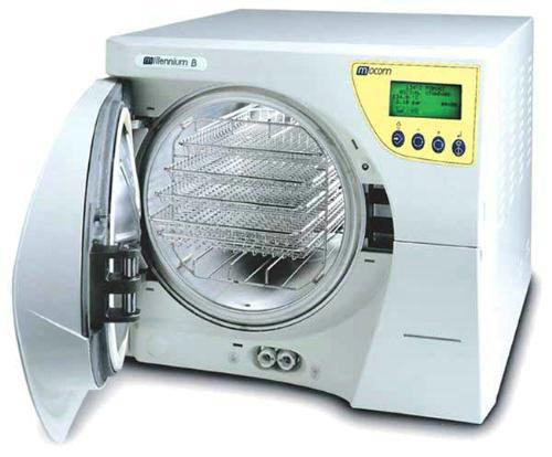
Поставщики и цены:
Автоклав MILLENNIUM B
Автоклав MILLENNIUM B — Высокотехнологичный паровой автоклав для использования в стоматологических кабинетах и медицинских учреждениях. Стерилизатор отвечает всем стандартам безопасности.
С помощью автоклава MILLENNIUM B можно быстро стерилизовать любой вид инструментов и материалов.
Автоклав имеет большое число опций и запатентованных деталей.
— Электронное микропроцессорное управление;
— Система мгновенной генерации пара;
— Многоязычное программное обеспечение;
— Встроенный принтер;
— 11 циклов стерилизации;
— Фракционная вакуумная система полностью удаляет воздух из камеры;
— Вакуумная сушка удаляет остаток конденсата в камере и позволяет полностью высушивать содержимое загрузки
— Выбор режимов предварительного нагрева в зависимости от частоты использования прибора и режимов в зависимости от типа выбранной программы;
— Наполнение внутреннего резервуара дистиллированной водой как автоматически, так и в ручном режиме
— Возможность подключения к ПК для считывания сервисных и пользовательских данных.
Автоклав MILLENNIUM B Технические характеристики
— Напряжение: 220/240 В
— Мощность: 2300Вт
— Внешние размеры: 480х420х560мм
— Вес: 54 кг
— Водный резервуар: 6 – 10 циклов;
— Размеры камеры: 250 – 350 мм;
— Объем камеры: 17 литра.
Назначение оборудования — Автоклав MILLENNIUM B
Автоклавы371 наименование, 47 производителей, 3 спецпредложения
Стерилизаторы515 наименований, 70 производителей, 2 спецпредложения