
IFILE No.
SERVICE MANUAL
High-pressureSleamSlerilizer
MODEL NO.
Labo Autoclave
MLS-37S1 Ll3781 L
~--
ITEM NAME PLATE
• Model No.indication
R""N,r:; LABEL
+Model No. and rated power
supply voltage are indicated here.
Model No.
Rated Voltage
Plug
Productcord No.
MLS·3751L
AC 120V
131699501
MLS·3751L
AC230V
131699502
MLS·3781L
AC230V
131699401
MLS·3781L
AC230V
131699402
Photo: MLS-3751 L
INDEX
1. Safety Precautions in Servicing Work .................................................... ·············1
2. Specifications
...................................................... ·········································2
3. Outside Dimensions ...............................•...........•...........•........................... 3"""4
4. Names of Parts and Operations ...................................................... ··············5-6
5. Construction and Functions ....................................................................... 7 . . . . . 10
6. Piping Diagram and Wiring Diagram ...........•...........•...........•.................. ·····11~12
7. Process Flow and Operations .................................................................. ··13~21
8. About Various Modes .. · .. · .. · .. · .. · .. · .. · .. · .. · .. · .. · .. · .. · .. · .. · .. · .. ···· .. · .. · .... · .. · .. · .. ·· .. 22 . . . . . 27
9. Temperature and Pressure Adjustment and Checking .................................... ··28 . . . . . 32
10. Thermistor Temperature Characteristics /
Altitude. Atmospheric Pressure and Boiling Point in Standard Atmosphere················ 33
11. Circuit Diagram ...................................................... ······································34
12. Troubleshooting ...................................................... ································35~44
13. Disassembling Procedure .............•...........•...........•...........•...................... ··45~50
14. Instruction Manual .. · .. · .. · .. · .. · .. · .. · .. · .. · .. · .. · .. · .. · .. · .. · .. · .. · .. · .. · .. · .. · .... · .. · .. · .. ·· .. 51 . . . . . 63
15. Parts List .......................................................•...........•...................... ··64~71
16. Instruction Manual of Works for Optional Parts ··· .. · .. · .. · .. · .. · .. · .. · .. · .... · .. · .. · .. ·· .. 72 . . . . . 79
REFERENCE No. SM6610004
1. Safety Precautions in Servicing Work
Please read the "Safety Precautions" section carefully to prevent any accidents during service repair and provide a safe product.
• Loss or damage which may result from failing to heed these precautions and degree of their urgency, the precaution
have been classified ioto the three categories
&Danger
&Warning
&Caution
This indication shows the content of the result in the death or serious injure of the operator or
other persons.
This iodicates a potentially hazardous sitoation arisiog from the mishandliog or mis-operation
of the unit which, if not avoided, could result io the death orserious iojury of the operator or
other persons.
This iodicates a potentially hazardous sitoation arisiog from the mishandliog or mis-operation
of the unit which, if not avoided, may result io mioor iojury of the operator or other persons
and property damage .
• The figure sign classifies the contents that must be heeded, and is explaioed. (The followiog sign is an example.)
6.
1bis symbol calls attention to a danger, warning or caution, so please take care.
0
This symbol calls attention to an action which the operator is prohibited from performiog,
so take care .
•
This symbol calls attention to an action which must be performed or which the operator is
iostructed to perform, so tske care.
&
Warning
Always unplug thc;unit when carrying out inspection or repairs.
C
PI_pull 0lIl: a
Pl""=' fUIlPly phi'
• Always unplug the unit from. the outlet when assembling,
disassembling. inspecting, or replacing parts.Failure to
observe the above could lead to electric shock. or injury.
6)
Always return the wiring to its original condition after carrying
out inspection or repairs on the unit.
&
• Tighten the lead holden so that the lead wires do not
touch revolving parts, high-temperature parts,
high-pressure parts, or edges (sides) of parts. Contact
could lead to ma1fimctions, electric shock, or tire.
~
Take sufficient care of electric shocks.
c.utiowl of 1111
6)
• Take sufficient care of electric shocks from the charged
parts '" lead temllnals.
electric: shock
Always use specified parts when repairing.
0
0
• Parts marked with it are safety parts.These parts are
important in maintaining safety. While replacing, always
use the specified parts.
0
0
• Do not splice the power cord, plug it into an extension
cord. or use it with multiple plugs in a single outlet.
Failure to observe the above could result:in electric
shocks, heating '" fue.
• Always replace damaged or worn power cord or lead
wires.Failure to observe the above could result in electric
shock, beating or tire.
• Confirm that there is no dust and that the plug is secure,
inserting it all the way in. Dust or bad connection could
result in electric shock or tire.
Caution
Beware of burns due to high _perature.
• Take care, as after operation the chamber door, chamber,
and piping sections are extremely hot.
Always wear gloves when repejring or inspecting.
&
power cord, heating. or pulling it could result in damage.
• When repajring, always use the part listed on service parts table for the appropriate model and appropriate tools.
Also, under no circumstances are modifications to the unit to be carried out.
Failun: to observe the above could result in electric shock, heating or fire.
&
@
_,_
• Do not damage or change the power cord .This may lead
to electric shocks or fire.Placing heavy objects on the
• Use gloves to avoid injury from. the edge ofmeta11ic
surface.
&
&
-1-
• Measure the insulation resistance after repe:irs and
con:fum that is at least 5M (1 .
A problem in the insulation can lead to electronic
shock.
• Confirm that the position of attached parts, condition
of the wiring, and soldering, or crimp connections are
normal.An abnormality can lead to heating, :fire or
electric shock.
2. Specifications
Product Designation
Labo Autoclave (High-pressure Steam Sterilizer)
Model Designation
MlS-3751/3751 l
MlS-3781/3781l
Power supply
120V unit: 120VAC ( 50/60Hz ), 15.BA
220V unit: 220VAC (50/60Hz), 9.1A
230V unit: 230VAC ( 50/60Hz ), B.7A
220V unit: 220VAC ( 50/60Hz), lB.2A
230V unit: 230VAC (50/60Hz), 17.4A
Power Consumption
1.9kW ( 120V only), 2kW
4kW
External Dimensions
47B(W) x 632(D) x 74B(H) mm
47B(W) x 632(D) x 965(H) mm
Weight
Approx. 61 kg
Approx. 71 kg
Internal Capacity
57l
BOl
Effective Internal Capacity
50l
75l
Chamber Dimensions
370 (dia.) x 415(D)
(Effective depth including cover: 463) mm
370 (dia.) x630(D)
(Effective depth including cover: 6BB) mm
Chamber Material
SUS304 (Austenitic stainless steel)
Sterilization Temperature
115°C - 135°C
Melting Temperature
60°C - 114°C
Heat-retention Temperature
45°C - 60°C
Thermometer
Thermistor, digital display (25°C - 141°C)
Safety Valve Releasing Pressure
240kPa (34.Bpsi, 2.4bar)
Pressure Gauge Range
-0.1 - 0.4 MPa
Timer
Sterilization
1 min. - 5 hrs.
Melting
1 min. - 5 hrs.
Heat-retent
Timer
72 hrs. fixed
1 week (Designation: Year, month, day, hour and minute)
2 liter Polyethylene tank
Exhaust Tank
Warning and Safety Functions
Pressure safety valve, overheat prevention device, dry-scorch prevention,
cover interlock, excessive pressure prevention, earth leakage breaker
Max. 75dB (A)
Sound Pressure level
Stainless steel baskets - Large: 1, small: 1
Accessories
Stainless steel baskets - Large: 2, small: 1
Drain hose: 1
Exhaust tank (1), exhaust tank at rear side (1), tank mounting bracket (1) and tip-resistant metals (2)
Optional Accessories
Object temperature sensor, external temperature sensor,
printer, stainless steel basket (large), stainless steel basket (small),
punching basket, sterilization can
·Please consult us about the model number, price, delivery date, etc.
including other optional accessories than shown as above .
• The specifications may be subject to change for improvement without prior notice.
-2-
I Front Side I
Lateral Side
•
I
eN
-..j
0'1
<1~
oc::
en
o
1
CD
r

1
I
I
-
~
~
c-
r~ :a
I
1
II
100
=W
~
1159
420
678
=
=
=
=.
l:: II}
g
en
1
C/I
en

C/I
c)"
:::J
;..c:1
---,
.
.
·
.
~
426
607
673
689
766
:::J
o
CD
:::J
9
'-
100
CD
=
=
=
=
==
==
=
=
=
=
=
=
=
ill ·· 1c::::::J1
D
~
r-

~J
l
3
c:
1
I.
o
CD
3
1
I
75
t-
en
0..
632
~
......
......
1
478
oc
~
~
'"
""
""
g
71 66
~
3
3
~
:::J
I Front Side I
Lateral Side I
•
w
-4~
1;-1
632

D
=
=
=
1!1
['II
•
00
......
r
oc::
c:
CD
!if
I
I
I
75
..--
-..j
g
3
CD
::::I
CJl
c)'
::::I
CJl
=
=
=
=
=
=
=
==
==
=
·
· 1c:::::J1
r""
'--..J
=
=
=
=.
~~
.
.
·
~9
.
~
426
607
673
689
766
171 66
o.n
...,
...,
<=>
~
4. Names of Parts and Operations
»
Rear.lde
~"
~
+-__~~
~~=~~2r~~~~pno~'~U~~~~IW~~~+-______________________
Steam is discharged through
this port if pressure in the
chamber rises abnonnally.
•••
•
MOVIIbie handl.
pulling toward you.
---=c-::::-----,I
r
Handle
Use for opening/closing the
cover.
P.....UNa.ua.
Indicates the pressure inside
the chamber.
Exhaust tank
Exhaust tank ,---J~
on the rear side
•
•
. . / - 1- -....._ _ _ _- .
~
I
"
~j:-l::::;;:;;;::';'7V~/t11C;;;;;~;;;;;C~0YII~r;;;;;;;;,,"~
~r-~~
~
~
C' 0
-l / ~
CQllllllr to shut the chamber tight.
It is lined with silicon rubber
pecking.
~
mn
I~
~!
-
@
II
~
G~p
...
oH)~-~c-::~r'lch~
L rJ
f-Co-nd-e-'n."e"."'."'tea=m"e"m"';H'-ed--+-J.~
.l;"",J] J
from the chamber.
~
•
Control panel
Used for unlocking the cover.
The covar can be unlock8d by
pressing this handle down and
~
=
'8
If
~v
V
•
_
.
.,...
R""""" thO """,r to ",nnee! th.
optional printer to the product.
-••-......JI---C~~
Tankcua
Encases the exhaust tank.
•
'Ii
C ••tar
.
Exhau.thOH
Sends steam and air in the
chamber to the exhaust tank.
"
:
~J-</
C==~~~==~--Rtfr~4
~.~!.!
Packing.
Hose in tank
'
Ii.
f-::-------'====----c-+---t+
,,"f+; p.f!
Converts steam discharged
from the chamber Into water.
Exhu.t valve
Manually opening/cloeing valve
uaed for draining heating water
from Ihe Ohamber.
Drain outlet
~~
~
-5-
Heating water III drained from the
Ohamber Ihrough this outlet.
Connecl: the included drain hoee
to drain heating water.
Control panel
Cover lock lamp
II
IndicaN hi _ tim., rem .... ing
IndicaN hi nlu. of the currvnt
proce. with • flitbring bar.
tm., llerilizdon qd8, exhawt
U~ "" wIIIIn opI~on.aart.
with . . COlIer locked.
!D, cautionary m~ .rror
mMIIIIgIIl, dIIte IIIId voice ~id.
Mltting.
,bulla" .
WhIll1 the optlona' obfect
tlImperlltUre .,".or I, In.lalled
and thl' object templll'&lure
button '- preMed, the I~ IIglU
up and the llerlllzatlon tllTlllr II
controlled by !he ~rature of
Indicates Iha _18cIed lblrilizRliDn
cycle with • Iii limp.
I
...,.ratu. .,
IndicaN hi currtlnt
llerilizdon Nt I8mpendur.,
mIIlting MI temperature, IIIhBUII:
IIIIrling templill1llUre, date,
hourimllUlM and voice guide
MIttIng.
obfMD to be .....lIzed.
,lamp
LIghts up wh8l'l the chamber 'Intemally undlr prusure.
Thlllllmp Ilghtl up whln thll
button '- pl'UMd.
. IBBI
...
IBBB
I
v-~ ~
,-
fo :
lo, •
~-
BAtI'tD
~~
~~
~
''';
.:-:
Timer I
s_ thallma untiliha liar! of
operation.
' bUtton
Indates changa 01 MIllIngs and
MIllIngs 01 CUlTlll'lt op8l'llllDn on
II1II digital dilplays'lnd II.
lJMd Ibr IlItIIng and dlRnglng the
sIIIr1llz1lllon tempM'atul1l,
sItIr1llz1lllon 1m., nwllng
I8mpllllLlure, rnellng Ima, hINt....ntion tamperw.tul'8, 1IIChI.u.t
I8mperalure, sIIIrt timer and
..,.ust rate.
Stop I
Stope operdon and cancelli
tilnllr Htting. and hINd-l'lMntion.
lJMd In engage the cooling modi!
clnlng IIXhaulilng.
Start button
StarIti opaIW.tlon and IIm.._
operation.
Time I
Current Ilmlli5 DlICUld on
clgital dllplay I.
Model No.
SIIIIIca .ny 013 progran-.1IIId <4cydIII (toIII1 121111111c101ll).
-6-
r
5. Construction and Functions
_Names of parts and functions are common to Series 3751 U3781 L. The photo shows Model MLS-3781 L.
. Part name may be
I
I
list when you place an order.
1
2
3
7
4
,
No.
Part Name
1 Pressure gauge
2 Tank
3 Front panel
4
5
6
7
8
9
10
Richt side Danel
Side panel. R
Left side panel
Side panel, L
Safety valve cover
Back side Danel
Handle, frame
Function
Bourdon tube pressure gauge for displaying pressure in the chamber
Tank for exhausting air in the chamber
Front side frame constituting the appearance of the temperature
detector
Constitutina the richt side appearance of the unit cover
Right side frame constituting the appearance of the unit
Constitutin the left side appearance of the unit cover
Left side frame constituting the appearance of the unit
Plate to block steam blOW'ing out when the safety valve is actuated
Richt side frame constitutina the appearance of the unit
Handle for moving the unit
-7-
1
13
12
14
2
15
11
16
17
Right Side
No.
11
12
13
14
Part Name
Valve assembly, 1/28
Fan motor
Chamber set
Chassis
15
Caster
Function
Manual valve for draining the water for heating the chamber inside
Air blowin~ fan for coolina the chamber
Chamber to seal UD steam and Derform sterilization
Base plate to fIX the arrangement component parts and support
them
16 Pressure sensor
17 Thermistor assembly
Caster for moving the unit. 4 casters are used. Equipped with lock
function
Semiconductor sensor for detecting the pressure in the chamber
Sensor for temperature detection
-8-
20
21
18
22
19
23
24
25
26 (The operational
unit body is in
this unit.)
i i
II
-9-
27
28
No.
Part Name
27 Packina, chamber
28
29
30
31
32
33
34
Lid set, chamber
Heater cover
Packing, panel
Sheathed heater set
Lock shaft.
Panel
Circuit breaker
Function
Fitted to the lid by sealine oackina for sealing the chamber
Chamber see line lid which can be ooened and closed Quicklv
stand on which sterilization object to be put In the chamber Is placed
Packing to seal the gab between the dlamber and the panel
Heat source heater to generate sterilizing steam
Part for locking to seal and fix the chamber and the cover
Panel to vertically oartition the chamber and the cover
Electric pert to shut down the power supply circuit in case of an
over-current in the unit
-10 -
6. Piping Diagram and Wiring Diagram
• Piping Diagram
HOSE EXHAUST
I JOIN'[ L R1I4 x G1I4 FLARED
SAFETY VALVE
AS~
(560)
r::V~
PIPE
HOSE TANK
JOINT, ORIFICE ()1.8
/
AS~
SAFETY VAlVE

.~
HEATER
AS~
ELECTROMAGNETIC VALVE NC
PIPE, EXHAUST
PIPE COOLING
rs
PIPE ASSf,
PRESSURE GAUGE
'"
SENSOR, PRSSURE
NSK -BAOI OB -092
HOSE, IN TANK
PRESSUR GAUGE, 350P
PIPE ASSf,
PRESSURE SENSOR
JOINT T VACUUM
JOINT T CHAMBER
TANK, MLS -3781
VALVE, VC12B1-F
VALVE ASSY DRAIN 3781
PIPE ASSY,FREX .l250
- 11 -
• Wiring Diagram
11iERMOSTAT
HEATER
(MANUAL RE1IIRN)
=
51: Rl
16 C
3
P
---D
81: OJ
51:R2
81: Q2
J
lIiERMO
1
HEATER
PIISSURE
1 BREAKER
10
L,J
81 :Ql
I
-
U=:::J L----D ltj I
SW
Q
,--------~
I PS
3
gmj
un n;; lli®l:'":.ECT TEMP
81'~' ~ e!
SENSOR
51:'
14 ~13
LCNlLJ LOOfiJ
IDl'TIDNJ
J.d 13 r!d 1
~
3
~
2 NC ,
0--0 n-
51:W
,
81: V CN9
~
"
I
'~ RELAY ~
7 5
~ 8
3
4Wli
B
I
U~1
auo32
I
B.<m11Y
FOR COCK
I
P.C.B.ASSY ,CONTROL CE
~l9~f+tirB:3t1fCN7
~H 1 r
g
~.-----,'
CN5
A3781CE ~ ~
1378ICE
OPllONAL PRINTIR CONNECllON
WR
~n
,
- , - - - - - H CN3
,
2
'=5
~
~
[iiiii]
C-UD-:-~
F.~137~81~~~~tf~"l"
INC,
1 5
HANDLE LOCK SOLENOID
mt 1
NC
§]
EXHAUST VALVE
n--------n1
~SP
LOCK SHMT
cd
S"""R
C
51:Rl
SClENDID
CN201 Il=~SPPCB ,,JL,',f)"D7S1CE
P,C.O. Am, DISPlAY 3781
aRCUIT
3
D DS -PCB OS
CN103rl~~=
CN10l
DD
DD
TERM~L
BLOCK
"---_L--=~+I:TlI--t=
L=h
sLilllill
I
~II I
I
1
5
'~-
'1Qj!J 3 ,
MU'ER ~D-,~+t~f2~~~~;;~~tt"~~~'·~·IT17~"~=r5F~3n;'C~E-rIl-----~
"", •• ,.,
~c::Jl
~
22OY: 8220 3781
~vn
llIANSFORMER
~
.,
~-~~
~SA
~--~
COOLING FAN
FQ
l'1!.N:Bl2G 3751
22OY: IWG 3781
nov: Bl3Q 3781
I
51: P.C.8,ASSY, EM0l51 CE
81: P.C.8,ASSY, EMeJ781 CE
11OV: 03751 CE
11OV,13OV: N3781 CE
2A
37S1L(12OV),3781L(23OV ENTElA):
I
Cl7811N1RA
one! MOOEl5: (3781 CE
POWER
TRANSFORMER
*
Note) 51 in the figure shows MLS-3751 L, and 81 shows MLS-3781 L
- 12-
7. Process Flow and Operations
(OOperations and displays
IOperations and Process!
Digital Display I
Turn ON the power.
STAND-BY
I
Digital Display II
Bar display "- - -" is displayed for the
Boiling point setting temperature is
displayed for the first 4 sec. Thereafter,
first 4 sec. Thereafter, the display
the display changes to stand-by display. f - - changes to stand-by display.
~
Put sterilizing object
and close the cover.
Setting temperature is displayed.
f-However, The temperature in the
chamber is displayed by pressing the
"... " + "T" buttons at the same time. If
the temperature is lower than 25"C, "La"
is disolaved.
Setting time and cycle are displayed
alternately. However, the water heating
temperature is displayed by pressing the
"..... + "..... buttons at the same time. If
the temperature is lower than 25"C, "La"
is disolaved.
I
Press the start
button.
"COVER LOCK
" lights up and the process monitors flicker.
Temparature in the chamber is
f-displayed. However, if the temperature
is lower than 25"C, "La" is displayed.
HEAT
f--
STERI (MELT )
r--
Temperature in the chamber is
displayed.
r--
r--
Temperature in the chamber is
displayed.
r--
Kemalnlng smnllzatlon orne IS CISPISyeC. However,
I
EXHAUST
1""---------
Nothing is displayed. However, the water heating
temperature is displayed by pressing the ~ ... ~ + "....
buttons at the same tima. If the temperature is lower
than 25"C. ·Lo~ is displayed.
the water heating temperature is displayed by
pressing the""'~ + ..... ~ buttons at the same time.
NOlmng IS cisplaye~. nowever, me WSIer eaung
temperature is displayed by pressing the" ..... +
....... buttons at the same time.
_._._._._._._._._._._._._._._._._._._._._._._._._._._._._._._._._._._._._._._._._._._._._._._._._._----
KEEP WARM
Temperature in the chamber is
displayed.
f--
f--
Elapsed keep-warm time is displayed_ However, the
water heating temperature is displayed by pressing
the tt... w + ~ ...u buttons at the same time_ By pressing
the ttRESERV" + ~ .... at the same Ume, the elapsed
keep-warm time is displayed in minute_
STERI/KEEP WARM MELT/KEEP WARM
---------- -------------------------------------------------------------------------------------------------------COMPLETE
r--
Temperature in the chamber is
displayed. However, if the temperature
is lower than 25"C, "La" is displayed.
I
I
pen me cover ana
take out sterilized
obiectCs).
I
STAND-BY
~
"COVER LOCK
r--
Bar display"
" is displayed. However, the
water heating temperature is displayed by
pressing the .... " + MT" buttons at the same
time. If the temperature is lower than 25"C,
"Le" is displayed.
"goes out and the all process monitors light up and the "COMPLETE"
flickers.
Setting temperature is displayed_ However,
the temperature in the chamber is displayed
by pressing the ... " + MT" buttons at the
same time. If the temperature is lower than
25"C, "Lo" is displayed.
Setting time and cycle are displayed
alternately_ However, the water heating
temperature is displayed by pressing the ... +
"T- buttons at the same time_ If the
temperature is lower than 25"C, "Lo· is
D
f--
displayed.
- 13-
.....1 '0)
• Liqyid Sterilization (]-1 1-2 and 1-3)
Te
"". --
~
"",powLIW.
'"
IS.--
Sterilization settinlte~ Exhaustsettinlte~. -
~
~
....
'I
'I
Lid !ION
f------- - - - - - - - - -
•
~
-.
'I
...
~
,
Sterilization
,
Coolilll
OFF at boiling
r...J!.Ol!!!;+7'C __
.....
_
~
---------
CD
---------t
-=n
--------1-_
,
0'
:E
n
:::r
.,II....
~
--------~~
~f-----
• •••
Exhault valve (NO
Handesolenoid
(Unlocked bypower-ON)
F~
Dilital c:isplay 1
Dilital c:isplay 2
Processmonitor
,-
...,
~..
...
ShortBeep
... ~ I"
~"
I
~.,(1";m••
;
Rllmainilll starilizatian
,~
!
H..ti"lll
H. .ting2
Exh.uat 1
Sterilization
""
,-
...
Temp. in Chamber (Displayed lit hillher than 25'C)
"',-
n
1/1
1/1
Heater relay
Speaker
.,"tI
o
-to
i
.... ---__
i
.'
----------,
,,"
;,
." ..."..............-"- - - - - - - - - - -
••
~
,
SteriliZlltionutl:imll
- f----- --- ---------
HeaterTriack
'I
"',-
Udapen
------ --- ------f----- --- ---------
r-.
~
Corq,letion
R""chi..-
- - - - - - - - - - - - - - - f - -Imin.
---
65"C- - - - - - - - - - - - -
0""'"-
Heatilll
Boiling point
A
BoilinlPoint-
,
Airpurp=
Heatilll
"',-
i
!
~
Corq,Iet;ion
>
nStorilization/Koep Warm (2-1 2-2 and 2-3)
Heatin
1 'I
Temp.
Lid OIOM
•
•
,
'I
Start
•
Sterilization
'I
Reaohinl
set. temp.
Boilinl point
Press.
Sterilization settingtemp. --- ---------------
Heatin
•
,
•
,
,
Cooli
Compllftion
Stand-by
'I
,
Lid open
Ster1IIZ11tloneettlme
--------------- ----------------
== • • • • • • • • • • • • . ~:~~• • • • • • • ·.~~==:7~'~h~,:.===!1- -___
i"---------I-ot.I'.
--1------ __.+__
~~
i
----~~
....;...........
i
._.L ""------------------------- ------------------------ ------------------i----"r-t-----'--+---1
~
••
HeaterTriack
/
,~
••••
i
••••
Heater relay
Exhaust valve (NO)
Handesolenoid
(Unlocked bypower-ON)
Fon
___________~__.k_.'~~~~~~.i~~~i:~~~·~~~~~~~~~~~~~~~~~..~~~~~~~k"
Digital display 1
,,-
. nemaininl sterilization
...;.r-_"l
Digital diSPlay21....._ _...
...;."~...
Process monitor
i"(1'''m~
It Stand-by >
I...---...
-"-....;.r=--;--'TV'-----"T"-----"T"---"T"--T
..
...
...;.-._;"_"'
__
"""._'~(D_;..i-'...
;...d_"_h..
;;..._'_"_._"_25""..;.)...,-...,--------...,----~..T....----..;.-~"
I
Heatl1'll'2
Starlllzation
Keep-wann elapsed
time
Exhaust 1
I"
KellJlwann
Stand-by
Comph!ll:lon
>
• Melting/Keep Warm (3-1 3 - 2 and
3-3>
When the mettlna: temp ....ture II Ht at hl&her than l05"C, flXhault. aperatlan II performed for 8 mlm..t boIllna: pHrt + 5"C .fter heatlna:.
T.
m,.--
pJr_.
'"
p~ ss.--
Meltingsettingtemp. --
Keep-wannsettingtime ---
0 .... --
•
""-
He.tinl
Meltinl
~lhina:
'" ....
1 '1
Lid clo..
•
Start
•
,
•
"',,-
,
•
,
'I
•
""-
,
~
""""-
>
72 hra.
". r------------_._-----_._-----_._-----_._--- "',
-----------
••••••
-r-
------_._-----_._-----_._--
r------- --
............... J-.--
Heater relay
•
Meltinl Ht time
--------------- -------- ---_.- ----_._- ---_._-----_._-----_._-----_._---
Hem:erTrieck
Completion
Lid open
---------------- ------- ----------------
----- ---
Coolinl
•••••
Exhaust valve (NO)
Handesolenoid
(Unlocked bypower-ON)
Fon
....
.~
Speaker
Digital display 1
Digital display2
Proc8samonitor
""""-
I
....
....
~
ShortB.ep
• ."dBo,P
~
lieP(lOtim..>
T.....,. in Chaniler (Displayed at hilher then 25"C)
RemIIininl meltina: time
HtNrtina:l
W
Meltinl
Koap-warrn elapsed time
Elchauat 1
It
"'''-
W
Completion
>
.Instrument Sterilization (4=1 4-2 and 4=3)
T."" -Press. - -
.,L
a<
--
lJd~
•
:!..
•
Heating
Air pu ....
'I
•
,
H..ti
-.
Sterilization
'I
Boiling point
•
,
•
,
'I
Udopen
Reaohing
...
Sterilizationsettingtemp. -- ---------------- ------- ---------------- --------------OFF::ilinr
point +1"C
•
~Ietion
--
•
,
--
>
Sterilization_time
/i
---------.,.,li _________....
:
BoilinSpont--- --------------- --------
)--------- ....
/
OM.,
~
/'
:'
....
....
" ....
-+---+-+--,--£'. ~~~. ;:--+---------------.. ."'!----+---.-I
••
HeaterTriack
Heater relay
:
Exhaust valve (NC)
Handesolenoid
(Unlocked bypower-ON)
..
~,
Speaker
Digital display 1
1'--~-;;;;;~-.;;;,r--'II'----...,-----...,--~T.~m~'.,;;;"~c~..~""~w~(D~;-;;;;~.~d~.~'~h;;"',W~"";;;;"~"~"~};..._...-----T"----,/T.......---;;;;;~-~--.>"
I
Digital display 2
Processmonitor
~.ep('Otim",
1'-----;-1-
k
:
,. . ,---_.1....-""''',',....
momalnlna: sten IlAtion
St:.nd-by
Heatinl'
']
Heatinl 2
~
Sterilization
..
']
Exhaust ,
Exhaust 2
~Ietion
(3)Descriptions of process operation
G)Set the exhaust tank to the unit.
Fill the exhaust tank with water up to the "LOW" level and set the tank to the unit.
~Turn "ION" the power switch.
For the first 4 sec., the boiling point setting temperatura is displayed on the IDigital Display II and the bar
display "- - -" appears on the IDigital Display III ' and then the set temperature, set time or the cycle is
displayed.
Press down the handlij and pull the Imovable handleltoward you to open the cover. Fill the chamber with
water until the end of the water level metal of the heater cover is immersed in the water. Put object(s) to be
sterilized in the attached stainless-steel basket, set it in the chamber and close the cover.
@Heating process (Process monitor lamp: "Heating" flickers.)
After checking the detail of the cycle and settings, press the ISTART buttonl. Then, "Beep Beep" sound is
heard and the power to the ~terilization heate~ is turned ON to heat the heating water and generate steam.
At this time, the air in the chamber is driven out by steam. The steam at that time is discharged into the
exhaust tank where it is condensed to water. Also, excess steam which could not be condensed enough
flows into the back side exhaust tank at the back side of the unit.
After the completion of air exhausting process, closing of the c-x-;h:-:a-us-:-;t-v-::a~lvCle fills the chamber with steam
and raises the pressure. After starting, the COVER LOCK lam lights up and the cover can not be opened
due to interlock function.
@Sterilization process (Process monitor lamp: "Sterilization" flickers.)
When the temperature in the chamber reaches the sterilization temperature, the Isterilization time~ starts
working. During sterilization, the tern erature in the chamber is detected by the lateral thermistor (THI) and
the power supply to the sterilization heate is controlled by microcomputer. The temperature can be set
every i'C between 115'C and 135'C.
When the set sterilization time elapses, the sterilization process ends and goes to the next exhaust process.
@Melting process (Process monitor lamp: "Melting" flickers.)
This process is for melting culture medium, etc. The temperature in the chamber is detected by the lateral
thermistor (TH I) and the power supply to the ~terilization heate~ is controlled by microcomputer. The
temperature can be set every I'C between 60·C and 114"C.
@Exhaust process (Process monitor lamp: "Exhaust" flickers.)
<For INSUMENT STERI>
By shutting down the power supply to the ~terilization heate~ and opening the lexhaust valvij, steam in the
chamber is discharged into the exhaust tank to perform cooling.
This process is to be performed when the sterilization object is instrument, etc.
<For other than INSUMENT STERI>
Shut down the power supply to the ~terilization heate~ and keep the lexhaust valve ~Iosed so that the
temperature in the chamber is cooled naturally. When the tern erature in the chamber lowers down to the
preset exhaust temperature (initial value or boiling pint), th exhaust valv opens.
This process is performed when the sterilization object is liquid such as culture medium, etc. The
sterilization object is prevented from spilling out due to burst boiling.
(l)Keep-warm process (Process monitor lamp: "Keep Work" flickers.)
The temperature of sterilization object such as melted culture medium or sterilized culture medium can be
set and maintained every I·C between 45"C and 60·C and the sterilization object can be kept warm for 72
hours. (The keep-warm process can be completed by pressing the !lTOP buttonl.) The temperature in the
chamber is detected by the lateral thermistor (TH I) and the power supply to the Isterilization heate~ is
controlled by microcomputer.
@Completion process
<LIQUID STERI cycle/INSTRUMENT STERI cycle> (Process monitor lamp: "Completion" flickers.)
When the temperature in the chamber lowers down to a certain level, the buzzer sound "Beep" is issued ten
times, and the bar display"- - -" appears on the IDigital Display III to inform the completion of operation.
<Sterilization/Keep-warm cycle· Melting/Keep-warm cycle> (Process monitor lamp: "Completion" flickers.)
After the completion of keep-warm cycle, the buzzer sound "Beep" is issued ten times, and the bar display
"- - -" appears on thel Digital Display III to inform the completion of operation.
- 18-
(4)Descriptions of safety device actuation
eCaution sions
Caution Sian
Lid
Disolav Condition
Cover is not closed comDletelv.
When the START button is pressed, the
Cause/Checkina/Remedv
Press down the handle by force.
Press the START button after the temperature in
Hot
temperature in the chamber is higher than the
nreset temnerature.
Due to bending or clogging of the exhaust hose,
the chamber has lowered.
HOSE
abnormal pressure was detected more than 7
times durin" heatin"
(j)Operation is started without opening the cover
immediately after power-ON.
®Trouble with the lock shaft detection switch
door
Pull put the exhaust tank and correct
the bending of hose. Check the exhaust circun
for anv cloaaino.
(j)()nce open the cover and start the operation.
®Replace the lock shaft detection switch.
eError sians
El
Enror Sian
Lateral thermistor (TH1)
Open
E2
Bottom thermistor (TH3)
Open
E3
Lateral thermistor (TH1)
Abnormal temp.
E4
Object temp. sensor
Disolav Condition
Lower than 21"C Smin. after the bottom
thermistor becomes 90·C.
Lower than 21'C for 2min. after starting
and 2 min elapsing.
Higher than 139'C
Higher than 140'C
(TH2) Abnormal temp.
'
'
,
'
'
'
'
'
Cause/CheckinaiRemedv
Check the thermistor (TH1).
Check the thermistor (TH1) connector.
Check the thermistor (TH3).
Check the thermistor (TH3) connector.
Check the thermistor (TH1).
Check the Triack.
Check the thermistor (TH2).
Check whether or not the tip of the
object temp. sensor lips down into
the heater unit.
E5
Bottom thermistor (TH3)
Abnonnal tamp
• Higher than 110'C in heating I,
keep-warm process.
• Higher than 120'C in heating 2,
exhaust process.
E6
Unlocking of the movable
handle is impossible.
E7
Locking of the movable
handle' cover is
impossible.
E8
Abnormally high
pressure
E9
Low pressure
El0 EEPROM communication
error
• Higher than 140'C in heating 3, heating
4, sterilization process.
• Or, higher than set temp.+30·C
The detection switch is not turned OFF
even when the power supply to the
solenoid is turned ON and the solenoid is
unlocked.
• The detection switch is not turned ON
even when the power supply to the
solenoid is turned OFF and the
solenoid is locked.
• Lid detection switch is turned OFF
during operation.
• Lock shaft detection switch is turned
OFF durina oDeration.
• Pressure in the chamber is higher than
about O.33MPa.
• Pressure in the chamber is O.04MPa
higher than the saturated steam
pressure in the temperature of the
lateral thermistor at heating 4 and
sterilization processes.
• Pressure in the chamber is O.04MPa
lower than the saturated steam
pressure in the temperature of the
lateral thermistor at heating 3 ,heating
4 and sterilization processes.
Nothing can be read out or written from
or on EEPROM.
- 19-
• Check the thermistor (TH3).
• Check whether or not the exhaust port
is blocked with sterilization object.
• Isn't the amount of heating water
reduced and isn't the chamber is
heated wnhout water?
• Check for leakage of steam or water.
• Doesn't the lock pin catch?
• Check the cover swoch.
• Doesn't the lock pin catch?
• Check the cover swnch.
• Check the lock shaft switch.
• Sterilization object which makes the
exhaust difficult.
• Exhaust circuit is clogged.
• Exhaust port is blocked with the
sterilization bag.
• Deep sterilization can is used.
• Shortage of heating water.
• Exhaust circuit is blocked.
• Check and replace PCB.
-Hard limiter
When the temperature in the chamber which was detected by the lateral thermistor (TH1) rises to higher
than 140'C, the Triack and the relay control circuit is controlled directly by TH1 temperature detection and
the power supply to the heater is shut down.
This circuit is not controlled via micro-computer and it is reset automatically when the temperature lowers.
(Actuated in all processes.)
- Pressure safety valve
This valve opens to exhaust steam in the chamber and prevent abnormal pressure rise so that the pressure
in the chamber should not exceed O.25MPa.
(5) Functions of specific parts and cautions
<Deaver interlock
This is a safety device to prevent the user from opening the cover by mistake when the pressure in the
chamber is higher than the atmospheric pressure.
In order to check seating tightness between the lid and the chamber, micro-switches are mounted to their
lock shafts.
Also, 1 micro-switch is mounted for detection of the position of the solenoid for the movable handle lock and
2 micro-switches to the lid for detection of lid open/close status.
-When the cover is closed, the 2 micro-switches mounted to the lock shaft and the lid detects that the
solenoid is in the specified position, and "Beep" sound is issued and the operation turns to stand-by status.
- When the START button is pressed, the live solenoid becomes non-live and the end of the solenoid enters
the hole of the movable handle. By so doing, the movable handle is fixed and at the same time, the
micro-switch is pushed by the end of the solenoid and the position of solenoid is detected to start the
operation.
(Cautions)
If the START button is pressed with the cover lock being incomplete, the caution sign "Lid'"
appears on the digital display of the control panel and the buzzer sounds. This is to inform that the
lid is not closed up to the normal position. Therefore, the cover handle must be pushed down until
the buzzer sound "Short Beep" is heard .
• When the "Lid'" display appears, the following causes are taken account.
• Handle is not pushed down completely.
Since the temperature in the chamber is high, repulsive force (force to open the lid) of the
chamber lid packing is too strong to push down the handle .
• The chamber lid packing is removed and the lid bites a part of it.
®About the "door" display
Lock shaft is closed when the cover is open (detection switch "ON"), the lock shaft opens once as the cover
closes (detection switch "OFF"), and it closes again (detection switch "ON") when the cover closes.
In order to detect adherence to ON of the lock shaft switch, it is checked by microcomputer that the lock
shaft opens and then closes (detection switch turns OFF and ON.), and if it was not detected that the switch
is OFF, "door" is displayed.
(Cautions)
If the START button is pressed without opening the lid immediately after the power is turned ON,
the "door" display appears, but this is not due to any trouble. Close the cover once and then press
the START button to start the operation.
- 20-
@Back side exhaust tank
When the water temperature in the exhaust lank rises to make it impossible to condense steam to water,
the steam is exhausted into the back side exhaust lank.
It is the back side exhaust lank that recovers the steam.
(Cautions)
When connecting the exhaust hose to the back side exhaust lank, be sure to insert it so that its end
reaches near the bottom of the back side exhaust lank.
The water in the back side exhaust lank returns from the back side exhaust lank to the exhaust
lank. In case of incomplete connection of hose, water remains in back side exhaust lank and the
water may splash in all directions in the exhaust process.
@Thermostat
This is the final safety device to prevent abnormal temperature rise due to heating of empty chamber by
heater. The power supply is shut down when this device works. The thermoslat is of manual reset type. The
actuating temperature is 145°C±5°C.
The thermoslat is mounted to the bottom of the chamber. To reset it, remove the unit side panel and the
reset button must be pressed directly.
(Caution)
Since the thermoslat can not be rest at a high temperature, rest it when the chamber is cooled well.
@Chamber lid packing
Timing of the chamber lid packing replacement is 1 year as slandard. If deterioration of the edge, hardening,
remarkable deformation or lowering of elasticity is found, it must be replaced.
When replacing, tum OFF the power supply and then remove the chamber lid packing from the chamber
lid.
Make sure that no foreign matters such as dirt, etc. are sticking to the new lid packing and the lid before
mounting the packing to the chamber lid.
-21-
8. About Various Modes
Models MLS-3751 U3781 L are equipped with the following modes. As for the detail, refer to the pages of
respective modes.
Setting mode: Display of processing frequency, history of errors, etc. and settings. etc.
Test mode: Display of temperature and pressure in the chamber, adjustment of thermistors,
pressure sensors, etc.
Demonstration mode: Display of actual operation status and demonstration of operation, etc.
-How to enter into the setting mode
1. Tum ON the power switch.
2. When the ".A. "+ "SET/CONFIRM" buttons are pressed for
about 2 sec. while pressing the "START" button, "Short Beep
x 3" sound is heard and at the same time the decimal point on
sterilization
the Digital Display I flickers. (See the right figure.)
3. After the status has become such as in 2, when the "START"
button is pressed within 5 sec. while pressing the ".A."+ "T"
buttons, "Beep· sound is heard, and at the same time the
mode becomes the setting mode and model name and speech
language are displayed.
flicker
"c
1- 1
-How to cancel the setting mode
When the power switch is turned OFF, the setting mode is cancelled. Or, when the "STOP" button is
pressed to enter into the test mode and the operation in the "How to cancel the test mode· is performed,
the setting mode reset to the normal mode.
-How to enter into the test mode
Light-up Sterilization
A. In stand-by display
Enter into the setting mode according to the procedure in the Flicker
51e
"How to enter into the setting mode" and press the "STOP"
button. Then, "Beep" sound is heard and at the same the
mode changes to the test mode. The difference from the
normal mode is such that the decimal point on the Digital
Display I lights up. (See the right figure.)
B. In operation
When the procedure in the "How to enter into the setting
mode" is performed during operation, "Beep· sound is heard
and at the same time the mode changes to the test mode.
I
.lizati~
12 1
0:2'1
"c
Time
-How to cancel the test mode
When the power switch is turned OFF, the test mode is cancelled. Or, when the "START" button is pressed
for about 2 sac. while pressing the ".A."+ "SET/CONFIRM" buttons, "Short Beep X3" sound is heard and
at the same time the test mode returns to the normal mode.
-How to enter into the demonstration mode
1. Turn ON the power switch.
2. Start the reservation operation.
3. When the "Cycle selection" + "STOP" buttons is pressed within 5 sec. after starting the reservation
operation, "Beep Beep Beep· sound is heard and at the same time the stand-by is displayed and the
mode changes to the demonstration mode.
-How to cancel the demonstration mode
When the power switch is tumed OFF, the demonstration mode is cancelled.
- 22-
(1)About the setting mode
In the selling mode, product infonmation, factory setting, processing frequency, history of errors, boiling point
setting, exhaust setting, address, option I, option 2 and channel display frequency setting and checking can be
perfonmed.
II
Mode
II
II
Operation
II
I
Display
II
3 18
E n 9'
(j)Product
infonmation
Preset model name and
speech language is
I""""--==--"""""-:=::::-idisplayed.
(In factory. English has been
sel for 3751 or 3781.)
:::~[:::L~:~~r~:I'CLr"
I~FactOry setting
is displayed.
o...
@Processing
frequency
F'_',-,L""",-,L"""......,=alProcesSing frequency
is displayed.
'------""""
[email protected] of errors
@Boiling point
setting
When the "SELECT"
button is pressed,
the mode progress
(j)....~ ••• @)....(j).
IE
"""~
I:!.
01
_ _ _- - ' ' ' ' ' ' ' ' ' ' .
bP
100
RPe;
8 1
SR
[email protected]
IClJAddress
History of errors is
displayed.
Preset boiling point is
displayed. (In factory,
boiling point has been
set at 100"(;.)
Preset air purge time and
heater OFF temperature
are displayed. (In factory,
they have been set 8 min.
and 7"C, respectively.)
0
OP ,
1FbO
OP2
FFbO
[email protected] 1
[email protected]
[H
@)CH display
frequency
Preset CH frequency is
displayed. (In factory,
he frequency has
been set at 3000
imes.)
3000:
- 23-
(2) About sub-mode
(j»roduct information
Mode
II
II
Operation
II
II
Display
II
3 18
IQ)Model name and
speech language
display
II
"3781" or "3751" is
displayed. "JPn" or
r .......E
...i-n
"""'"-_
g
~·Eng. is displayed.
!
Time button
Preparation date
display (Note)
'
2001
"200703. 13" is
displayed. (March 13,
~~~~"""'"--3~2007) or fen is
!
Time button
3 ersion display
(Note)
O3•
U":-I.-""E..' r
f---....
!
operated.
"VEr 1.19" is
displayed.
,=-'-g=l (Version 1. 19)
Time button
"Model name can be changed by pressing the· ...·or "T" button during
CD the model name and speech
language display.
"Speech language can be changed by pressing the ·SET/CONFIRM" button and the" ...·or "T" button
during
CD the model name and speech language display. When the "SET/CONFIRM" buttons are
pressed again. the model name can be changed ...
"When the ·START" button is pressed while pressing the ·SET/CONFIRM" button, the content of the
change is written in non-volatile memory.
"When the "TIME· button is pressed, the mode changes in the order CD-+®[email protected]+CD"".
"When the "OBJECT TEMp· button is pressed during the product information display, all the LEOs are
light up.
«Note»
® Preparation date and @ Version display are altered depending on the specification charge.
~actory setting
"When the "START" button is pressed while pressing the "SET/CONFIRM" button, the alarm sound ·Beep
Beep Beep" is issued, and the setting is defaulted to the factory setting. When the "START" button is
pressed again while pnessing "SET/CONFIRM" button, the setting is defaulted to factory setting.
The following items ane subject to the factory setting:
(1 )Setting values for each cycle (sterilization temperature, sterilization time, etc.)
(2)Error information and frequency
(3)processing fnequency
(4)Boiling point and air purge settings
(S)Address
(6)CH display fnequency
- 24-
@Processing frequency
Total frequency
In the process frequency display, the total frequency of all cycles
and the processing frequency of each cycle are displayed.
• Each time when the "TIME" button is pressed, the processing
frequency of each cycle are displayed.
Processing
frequency
··ALL" stands for the total frequency, and "cSl" for LlQUD STERI,
"cS2" for STERI KEEP WARM, "cS3" for MERT/KEEP WARM
and "cS4" for INSTRUMENT STERI, respectively.
C cle-wise
·When the "START" button is pressed while pressing the
"--r--I~Cycl~e---.J1
·SET/CINFIRM" buttons, the total processing frequency and
1"""''--''......_..0.....,=1
operation frequency of each cycle are cleared.
R
S ,
C
--=''-' 'O.....,H ~~c:~~ I
L -_ _ _
@Hlstory of errors
Error No., error code and error occurring process No. are displayed.
The latest error data is displayed in the first place.
• The error No. is changed by pressing the" ...·or .... " button and
the history of errors can be checked.
The error No. can be recorded for 8 in number at the maximum.
If more than 9 errors occur, the oldest error is deleted and new
error is recorded instead.
·When the "START" button is pressed while pressing the
I Error code
·SET/CONFIRM" button, the error data is deleted.
(Total errors are not deleted.)
E
t
2 +-t
6 04--
Error No.
I
Error occurring
process No.
I
.Error Codes.
1 : Lateral thermistor (TH1) Open
6 : Movable handle Unlock impossible
2 : Bottom thermistor (TH3) Open
7 : Movable handle and lid Lock impossible
3: Lateral thermistor Abnormal temperature
8: Abnormally high pressure
4 : Object temperature sensor (TH2) Abnormal temperat 9: Low pressure
5: Bottom thermistor Abnormal temperatura
10: EEPROM communication error
< Error
occurring process Nos.>
Description
Process No Error Occurring Process
Process No Error Occurring Process
0
Stand-by
6
Heating 4
1
Reservation
SterilizationlMelting
2
Up to 90"C
3
Heating 1
Heating 2
7
8
From 90<>C to boiling poin1
9
Cooling 1
Cooling 2
4
Exhaust
10
Keep warm
11
Completion
5
Heating 3
THl
temp. rises up to
the preset temp.
Description
TH2 temp. rises up to
the preset temp.
Down to boiling point
Before cooling point
@Boiling Poing setting
Change the boiling point temperature according to the altitude of
the place for installation by pressing the" ...·or ..... button.
·When the 'START" button is pressed while pressing the
~OH Set temperature I
·SET/CONFIRM" button, the content of the change is written in
the non-volatile memory.
(The boiling temperature has been set at 100"C in the factory.)
• When setting the boiling point, refer to the table (P__ ) of the altitude and atmospheric pressure in the
standard atmosphere and the boiling point of water.
bP
,
- 25-
@Exhaust setting
-Heater OFF temperature can be changed by pressing the" ."
or "T" button.
(Heater ON temperature is fixed at the boiling point temp.+1 "C.)
-When the" ."or "T" button is pressed while pressing the
"SET/CONFIRM" button, the exhaust time can be changed.
-When the "START" button is pressed while pressing the
"SET/CONFIRM" button, the content of the change is written
in the non-volatile memory.
RP[j1
B 1
<!lAddress
-Address can be changed by pressing the" ."or "T" button.
This address is used for connection of the MTR system.
-When the "START" button is pressed while pressing the
"SET/CONFIRM" button, the content of the change is written
in the non-volatile memory.
@Option 1
-Change bit is selected by pressing the" • "or "T" button.
-Preset value can be changed by pressing the "TIMER" button
-When the "START" button is pressed while pressing the
"SET/CONFIRM" button, the content of the change is written
in the non-volatile memory.
SR
i
«Note» Do not set 9999.
- 26-
I Change bit I
OP2
FFbO
i
I Preset value I
@lCH display ferquency
CH display frequency is set. (CH is displayed when the total
processing frequency exceeds the CH display frequency.)
4 kinds of frequency of 1000 .. 2000 .. 3000 (Factory setting)
.. 9999.4 can be selected.
-When the "T" button is pressed, the frequency decreases and
when the"." button is pressed, the frequency increases.
-When the "START" button is pressed while pressing the
"SET/CONFIRM" button, the content of the change is written
in the non-volatile memory.
o
OP ,
lFbO
I Preset value I
@Optlon 2
-Change bit is selected by pressing the" • "or "T" button.
-Preset value can be changed by pressing the "TIMER" button
-When the "START" button is pressed while pressing the
"SET/CONFIRM" button, the content of the change is written
in the non-volatile memory.
Heater OFF temp.
11..)-_---,
IChange bit I
[H
3000
(3) Functions of test mode
1. Minute temperature display
When displaying the current temperature, the
value after the decimal point is also displayed.
1Displays 112.3"C. 1- ,
L
12°31
I
2. Expansion of temperature setting range
I
Temperature can be set from 20"C to 150"C.
Error is prohibited by the sterilization limiter.
Set value can be changed even after heating process.
3. Remaining time display in exhaust process
Exhaust remaining time is displayed on the Digital Display II. (in min.)
4. Pressure/Saturated steam pressure display
By pressing the "TIMER" button, the current pressure is the Digital Display I. (in kPa)
5. Forced exhaust
By pressing the "A" and 'STOP" buttons at the same time during stand-by, the exhaust valve opens.
The forced exhaust can be cancelled by pressing the "STOP" button.
6. TImer 60-time speed operation
While the "TIMER" and the "SET/CONFIRM" button at the same time, the reservation timer, process
timer and sterilization timer operate in 60-time speed. (It is preferable to perfonn the exhaust fast.)
7. sterilization process starUcompletion signal output
Buzzer sounds at the start and completion of the sterilization process.
(4)Functions of demonstration mode
1. Power is not supplied to the heater.
2. Process timer and sterilization timer operate in 60-time speed.
3. When the power is supplied to the heater, the temperature on the Digital Display rises automatically.
4. When the power is not supplied to the heater, the temperature on the Digital Display lowers automatically.
(For safety sake, however, the temperature does not lower than the actual temperature of TH1.)
5. Pressure Abnonnal is not detected.
- 27-
9.Temperature and Pressure Adjustment and Checking
(1)Adjustment of thermistors
The temperatures of the lateral thermistor, object temperature sensor and botlom thermistor can be
corrected manually. The temperature of the lateral thermistor has been corrected in the factory in advance.
Use the displays if the correction of temperature is necessary for validation,etc. The correction of
temperature is performed at 3 points, namely, 105"C, 121"C and 135"C.
For prevention of heating without water, check the heating water amount.
*Instrument to be prepared*
Thermometer that has been calibrated by temperature recording meter, etc.
Since the temperature is corrected on the basis of the temperature indicated by the thermometer, prepare
an accurate thermometer. The correction of temperature is performed as minute as 0.1 OC.
II
Operation
I
Enter into the test mode.
I
+
Select the instrument sterilization
cycle and set the sterilization
ISet the cycle, sterilization temp.
land time.
temp. to 105'C and set the
sterilization time at 1 hour.
t
Press the START button
Description
I
l
:like~
in the normal operation, heating,
and exhaust processes are
rmed.
I
I
I
II
~ EXSmple of normal diliPlay1
NO"
LEFT
0: ,yl
I
Release. ~
ISelect the thermistor you want to I
ladjust. (See the right figure.)
I
r
Press.
TIMER
IL
button
'-==
.....1.
Example of
oom>cIIon
The correction of temperature is
+
I tO 5EI~
Reaching 105'C and sterilization process
displayed only while the TIMER
I
Display
Lateral thermistor
button is pressed. When the
SELECT button is pressed while
pressing it, the display changes
in the order of -Lateral sensorObject temp. sensor-Bottom
sensor-Press. sensor. Select
the thermistor which you want to
adjust.
Obj ••, '.mp.
sensor
+
Press the •......or· A" button
while pressing the TIMER button,
and adjust the temperature so
I
Adjust at 105"C.
(Correction)
that it becomes the same
I
NO"
I
wi SELECT button I
to YBloc
001
TIMERI 3
temperature as the value
indicated on the thennometer.
+
When the START button is
pressed while pressing the
TIMER button. the corrected
Bottan
thermistor
Adjust at 105"C.
(Writing-in)
NO"
~
value is written in.
I
~ SELECT button
to 6 'Sloe
3) 001
EXHAUST: lateral thermistor
TIMER: Object temp. sensor
LEFT: Bottom thermistor
- 28-
I
3 : 105"c
4 : 121"c
5 : 135"c
1
Press the SETLCONF I RII button
to set the sterilization temp. at
121''c.
Set the sterilization temp.
Example of the lateral thermistor correction
display (in 121"C correction)
Reaching 121 "C and sterilization process
Perform the 121"C correction in
the same manner as the
correction at 105"C.
Press the SETLCONF I RII button
Adjust the temp. to 121 "C after
going to the 121 etc sterilization.
Set the sterilization temp.
to set the sterilization temp. at
135"C.
Reaching 135"C and sterilization process
Perform the 1350C correction in
the same manner as the
correction at 105"C.
Adjust the temp. to 135"C after
going to the 135"C sterilization.
- 29-
NO"
I
[2 IEloc
""'""111 021
(2) Adjustment of pressure sensors
Pressure correction of the pressure sensor can be performed manually.
Pressure correction is performed at 2 points, namely, in the status with the lid being opened and at 135 DC.
For prevention of heating without water, check the heating water amount.
I
Operation
I
I
Enter into the test mode .
I
..
I
Description
II
I
I
Display
Fix the 2 shafts found at the back
side of the cover by tape, etc.
and set it to ON status.
t
Close the lid once and then open
it.
..
Press the START button with
the cover being opened.
For adjusting the pressure when
the pressure is 0 (cover 'Open').
Normal display
The correction of pressure is
displayed only while the
reservation button is oressed.
When the cycle selection
button is pressed while pressing
it, the display changes in the
order of -Lateral sensor-Object
Selection of the pressure
correction display
(See the right figure.)
Release.
of ]
Raserv.
button
Press.
Example
nannal display
Cycle selection
button
temp. sensor-Bottom sensor-
~
Press. sensor. Select the
pressure correction display.
Lateral thermistor correction
display
( Cycle selection
button
Press the ~or "a" button
while pressing the reservation
buttu I and adjust the pressure
I Object temp. correction display
Pressure adjustment
(Correction)
[ Cycle selection
button
so that the pressure display valu
becomes 'P. 0'.
When the START button is
pressed while pressing the
reservatm buttu i, the
corrected value is written in.
1
J
Bottom thermistor correction
display
Pressure adjustment
Example of pressure
correction display
(Writing-in)
'-
e.1 rn
(j
Press the STOP butIpn and
Cycle selection
button
]

remove the tape from the shaft.
/
Pressure display value
- 30-

Corrected value
J
Select the instrument sterilization
cycle and set the sterilization
temperature at 135'C and the
sterilization time at 30 min. Close
the cover and press the STRAT
Set the cycle, sterilization temp.
and time.
~.
Reaching 135OC and sterilization process
Nonmal display
Release.
Press the "V"or ",6." button
while pressing the
SETlCONFIRM button
and
adjust the pressure so that the
pressure display becomes same
as the value on the pressure
gauge of the product.
When the START button is
pressed While pressing the
SET /DISPLA Y button the
corrected value is written in.
SET/COFIRM
Pressure adjustment
(Correction)
(See the Mght figure.)
The pressure gauge of the
product shows the pressure in
MPa and the pressure display
value in kPa.
button
Example of pressure
correction display
Pressure adjustment
(WMting-in)
Pressure
I
display value
-31-
Corrected
value
Press
(3)01ecklna the safety valve operation
'Checking procedure of the safety velve operation
I. Enter into the telt mo'" As for the .ntwirllllMlthod. _ ttl. PIIP d.scribirc th. wit mod •.
2. S.I.ct the in.tn.n.nt .t.iliution cycI.. ..t th • .twiliution w~nrtlnl .t 140"C .nd the .u.riliution tim.
at 10 min . ..,d ltart th. opwGon.
3. Wh.n th ........It p___ is owr. th • ..r.ty wI¥. i••ctu.t.d at.bout l4O"C1O.2tlMP. to b.lch.w.m from
*k
th,
IIidI.
4. Wh,n th, QOI'Ifimation if; cornplmd.•.t the ltlriliz.tion temp,r.tu ... at 135'C ..,d th, .t.ilization tim, .t
1 min.
5. Wh,n th, proeM, i. complil'tlld thelL,," the ,xhaLllt prac... IftIr ttl. complfiion of the ItlriliDiion pl'OCOlu.
tum OFF th, ~ to oomplm the confimlltion.
(4)Conformatlon of the THl and TH3 temperature.
When the '''''and ..... butlDns 818 pnIIIslKI at the same time,
the TH1 temperature ill displayed on the Digital Display I end
the TH3temperature ill displayed on the Digital Display II.
- 32-
-~NOW
12
12
I
I
I
I
"
10. Thermistor Temperature Characteristics /
Altitude,Atmospheric Pressure and Boiling Point in standard Atmosphere
-Thermistor temperature characteristics
Th1·Th3
Standard
Temp.
"C
Resistance
Standard
"C
Temp.
Resistance
Value M?
-10
-5
0
5
10
15
20
25
Temp.
"C
Value k?
9.71
7.17
5.33
4.01
3.03
2.32
1.78
1.39
1085
854
676
539
433
349
283
231
30
35
40
45
50
55
60
65
70
75
80
85
90
95
100
105
Standard
Resistance
Value k?
Standard
"C
Temp.
Resistance
Value k?
189.2
155.9
129
107.3
89.57
75.12
63.26
53.48
110
115
120
125
130
135
140
145
45.3t
38.6f
33.04
28.34
24.35
21.0f
18.2
15.84
- Altitude, atmospheric pressure and The Boiling point of water in standard atmosphere
Atmospheric Pressu ..
Altitude
(hPa)
-382
-300
-200
-100
o
100
200
300
400
500
61
1060
1049.0
1037.
1025.2
1013.
1001.4
989.5
977.6
966.
954.
943.
Altitude
(nmHg)
(
795.0
786.7
777.8
768.9
760.0
751.1
742.2
733.3
724.6
716.1
707.5
"C)
(m)
101.27
100.99
100.66
100.33
100.00
99.67
99.34
99.01
98.67
98.34
l8.
Atmospheric Pressu..
(hPa)
1900
2000
2100
2200
2300
2400
2500
2600
2700
2800
2900
(nmHg)
805.2
795.0
785.4
775.8
766.2
756.6
746.9
737.
728.5
719.3
7'
MO
~.
603.9
596.3
589.1
581.9
574.7
567.5
560.2
553.3
546.4
539.5
532.'
IBoil!n_!! Point
( "C)
93.72
93.39
93.06
92.73
92.40
92.07
91.74
91.41
91.08
90.75
5
320
825.
815.
.5
l4.)5
4000
,.4
47 .
46..
46..
!7.
• Environmental conditions for use of equipment
Atmospheric pressure 701.1 - 1013.3hPa
-As for the conversion of the atmospheric pressure(hPa(mba) and mmHg), see the following formula:
1mmHg=13.5951 X980.665X1 O"'hPa(mba)
-As for the calculation of the boiling point, see the following formula:
Boiling point =100+0.0367(P-760)-0.000023(P-760)2
P: mmHg
- 33-
CD
~
I
®
nnnn
_
~
t~
=
®
@
-*-iY
I
-
~o--
uuuu
=
--
:1
limiter
I
CD Power cord
@Triac
® Tanninal block
® Power switch
® Power relay
0) Power transfonner
® Protective grounding tenninal
@Coil
®
I
I
I
-
EMCPCB
Current fuaa x 2
'5OV SA
----j Ud switch
Fan
I
AC power IlUpply ~
datecIIon circuit
I
;M
'!'i'
"''''''>A
...
Main relay
control circuit
MlcrocompulBr abno
detection circuit
12V
I
all Hard limiter
Fan control
circuit
I
I
IComm~onll
h
5
pea
Circuit
Sound
circuit
I
I
III Sol~'"
S<>Ieoo;d
control circuit
wlw
control circuit
1
DC88V
I
6: 120V
3: 110V
2: OV
II T_
_ II To~"""~
d'cult
circuit
I
Microcomputer & Control Section
-
8:23OV
4 :22OV
3 :200V
2: OV
TH3
I ILateral
temp. II Low temp.
sensor
sensor
L~ OV
~ I,
. - =1 Co~=on
·" ·"
kef'
I
CommutaUon
circuit
.- -
··, ··,
ITriKk~""'"
circuli
DCpower E'! 5V
IlUpply circuli
-'!.5V
I
Ud_h I
TH1
Heater detection
circuit
.-
--
PCB
--1
'-""<ow
Voltage drop
detection cirtlUit
7
•" •"
I
Display·Operation
-
0)"
22OV123OV
,-
I
I
1Commutation 1ComrTMJtation
circuit
circuit
I
I
Lid detection
circuit
l
Control PCB
I
I SolenoKj I I ~:st I
Commutation 1
circuit
Printer
0 ptio
n
~
I I PrMeurecircuit
dIlecIion
11
Tamp. dllectlon
circuit
"'all, I
'-""< SY!Ich
delecllon
'-""<
"all, I I Psensor
....,.. I I Objed tomp_
sensor
del8clion swim
Option
TH'
11.Citcuit Diagram
Sterilization heater
1900W : 3751 L(12OV)
2000W : 3751,3751 L(230V)
"~400OW:3781,3781L
12.Troubleshooting
is not
when the
is turned ON.
(1)
main power billa• .
If the breaker Is OFF, tum nON.
(2) Check the power cord for any breakage.
If broken, replace the power cord.
Checking point by
tea..,
i
the P0'NW5Upply.
Tum OFF the main power supply and turn ON the power
switch of the unit, and check the conductivity.
If not conductive, replace tha power switch.
(2) Check the lead wire for removal or looseness.
(1)
Check the conductivity
ENTERA (or CE).
F....
;
Check tha lead wire for breakaga.
• od<el of
housing set
- 35-
(2) iIIILid" appears on the dsplay and procesl doe. not start.
1) Check the 2 shafts mounted to the nd.
Shafts
2) Check the position of the both lock shah.
Lock shafts
Push the shafts to make sure that they slide In and out
smoothly.
If the shafts do not slide smoothly,
(1) Check the springs lItted to the shalls.
(2) Apply grease to the shaft sliding perl
When the cover is opened,
(1) Check if the shalls are in due position
On just about vertical position).
(2) Check if the lock shafts open when pushlld outward and
they retum to the original position by spring force when
relaased.
If they can not move normally,
(1) Remove any foreign matter which is pinched and jams the
.hall
(2) Replace the spring, etc. If In trouble.
(3) Apply grease to the shaft sliding perl
- 36-
i.,.,,;~ awIlch Is not conductive
housing set M.
ON, replace the
Detection switch
;
lead wire for breakage.
Socket of the
housing H1:
replace the
housing set OS.
Between Black 1 and 2
Conductivity checking
positions
• Detection switch 1
Between Black 1 and
2
• Detection switch 2
Between While 1 and
Black 3
• Wire Nos. are
Indicated on the
Between Black 3 and White 1
connectors.
- 37-
Check that the housings in the same color are connected.
Check. the
connection.
(3) "___ ..,.,..,.. on the _
even when the cover Is closed.
1) Check the Items 2) and 3) of "L.Jd" appears on the display
and
does not start
2) Check. the conductivity the switch when the both lock shafts
(5) _
is
Correct Kif In trouble.
Since the switch is turned OFF when the lock shafts open, the
switch Is not conductive.
If the switch is conductive, rwplace the housing set M.
not .. "".... to tho twater.
1) Check the exhaust hose.
2) Check the hose in the exhaust tank.
3) Check if the exhaust hole i, blocked with any sterilization
otfect or sterilization bag.
Check. if the hose is bent or clogged in the product when
exhaust 'lank Is Installed. Correct Kif bent or clogged.
Check if the hose is bent or clogged.
Correct Kif bent or clogged.
Remove it if the exhaust hole is blocked.
- 38-
(1) Since
does not operate in spite that the voltage
is applied, replace the exhaust valve.
If the voltage is OV,
(1) Check the connection of the housing set W or V.
(2) Replace the "PCB set, controlTH set".
7.6Qfor 3751 L (12OV), 13.2Qfor 3781L
26.5Qfor 3751L (230V) and 3751.
If not, replace the heeler.
Check the resistance
value bet¥Men the
terminal block 1 and
relay- 6.
..
(1) C;;eck.1~' ~)",;"g"' "'b'y I 3781 CE for connection and
breakage.
(2) Replace the relay.
OV.
''''''''
(1) Check the housing assemblyB120 3751
8230 3781 for conneclion or breakage.
(2) Replace the Triac.
(3) Replace the "PCB set, controlTH set".
1 and D.
chamber.
It can be restored If a "Click" sound Is heard.
,,-f-
Press hera.
(8) ''!me" "-""" on tho _ .
Check the Item. 1) - "') of ·Power is not not .upplied to the
heeler."
If any trouble, correct it
- 39-
or 8220 3781 or
(7) Steam leaks from the periphery of the chal'l"tter.
1) Check the chamber lid packing and the chamber hard top
(1) Clean the contact pari of the packing and chambertop.
(2) Clean the contact pari of the packing and chamber lid.
(3) If the chamber lid packing Is deter1orated, replace It.
(8) Steam leaks from pipe and joint.
1) Check the heater mounting pari (lower side of the chamber)
for steam leakage.
If nuts are Iooeened, retighten them.
Checking positions
2) Check the pipe connection
(1) If the connection Is loosened, retighten It.
2 If the hose band is loosened,
lace it.
(St) Open error (E1) occ...., at the lateral thermistor (TH1).
Abnonnal tern erature rise of the lateral thermistor E3 occurs.
1) Check the connector connection
2) Check the resistance value of the lateral thermistor (THl)
(1) Check if the socket is inserted completely.
2 Check the lead wire for brea 8.
Remove the connectors from the "PCB _, control
completion" and check the resistanoe value beiw8en the
terminals of connector side.
Resistance range (90 - Ilot):About SO.O-
41.60)
Checking points
bvtester
3 Trouble with the "PCB set, conIroI TH set.
(10) Abnormal t.
Re lace the "PCB aet, control TH set".
.ratur. of the ob".ct t.m .rat..... s.nsor (TH2) (E4.occurs.)
1) Check the resistance value If the object temperature sensor
Remove the connectors from the "PCB set, control
completion" and check the resistance value between the
terminals of connector side.
Resistance range (90 - Ilot):About SO.O -41.60)
Checking points
bv .....
2 Trouble with the "PCB set control TH set"
Re ace the "PCB
- 40-
control TH set".
(11) Abnonnal teQJerature of the bottom thennlstor (TH3) (E5 occurs.)
1 Check the heBlin water amount in the chamb...
2 Check. the nem of "steam leaks from
I e and oint."
If the heati
Re
water In the chamber is d .... Bled, re enish it
Ir the steam leakl
rl
I
.,....+-
(1) Check connector insertion of the housing set X+ U(3751)
or D + T(3781). If not completely Inserted, correct n.
(2) Check the resistance value between the terminals of the
solenoid.
Range of resistance value: 160 - 1852
In cue of short-an::uit or breakage, replace the solenoid.
(3) Check. If the lock pin Is caught. Apply grease.
SolenoId
incomplete
connection.
Housing set DS
short-circuited with
housing
Detection switch
Conductivity checking
posilions
• DetecUon switch 1
Between White 2
.oo 3
* Wire Nos. are
indicated on the
Between White 2 and 3
connectors.
- 41 -
set DS.
lever being retumed, replace the
Movable handle and lid lock is not
r
;
for engagement of the lid. If not caught,
(1) Remove any foreign matter, which maybe sticking.
(2) If the lock shall retum spring is weakened, replace it
(3) If the lock shaft does not move smoothly, apply grease.
Checking position
is closed. If
Check the condudivity of the switch when
no conductivity,
(1) Adjust the switch mounting poaition.
(2) If no conductivity is found ever when the lever is pushed,
replace the housing set M.
Detecllon switch
If no conductivity,
(1) Adjust the switch mounting position.
(2) If no conductivity Is found ever when the lever Is pushed,
replace the housing set OS.
Conductivity checking
poanlons
• Detection switch 1
Between Black 1
and 2
• Detection switch 2
Between WhKe 1
and Black 3
• Wire Nos. are
Indicated on the
BeIw'I!Ien White 1 and Black 3
connect0r5
- 42-
4) Check the housing
Check the housing set Y(3751) or (3781), housing set
X+U(3751) or D+T(3781) fo~ connection and breakage. If
Incomplete connecUon or breaKaae Is found, correct n.
Re ace the "PCB set, control TH set".
Re lace the "PCB set, dis I
aet.
5 Trouble with the "PCB set, conlrOl TH ser
dis la
e Trouble with the "PCB s
..nSOl'".
'--+-
Pressure sensor
(15) Pressure is low. (E9 occurs.)
I
1) Check the Items 2) and 3) of "Abnormally high pressure".
I
1) Trouble with the "PCB set, conlrOl TH set.
I If any trouble Is found, correct It.
(18) Data can not be read from and written in memory. (E10 occurs.)
I
Replaoethe "PCB set, control TH set".
which connects
,l,.....,.p,...+-
Voltage (DC)
incompl&la
(2) Check the voltage between "+V" and
of the power
supply unit to make sure that about W is outputted. If not,
raplace the po'W'8I" supply unn.
Voltage (Ae)
,correct it.
Checking point
Checking point
- 43-
(18) No sound Is Issued.
If it is set at sound waming mode, change the
to ~Loud" or "Medium" to check that the sound
1) Check the lKlund setting.
2) Check the resistance value of the speaker.
Checking point by tester
3) Check the housing set.
4) Trouble with the "PCB set, control TH set"
lKlund volume
is issued, and
tell the customer that the sound Is not luued In sound warning
mode duri normal 0 eration.
Check that the resislance value at the both ends of connector
isabout8Q.
If short-circuit or wire breakage Is found, replace the speaker.
Check the housing set X+U(3751) or D+T(3781) for
incompleted connection and wire breakage. If any trouble is
found, correct it.
Replace the ~PCB set, control TH set".
Date and time~a~re~re~.~e~t~.------I~Oal~~~r"~"'!"'!'"!'''hli'"'iiiOiiTW.Tci8diLl
If lowar than
Ie pushi ng the
- 44-
13. Disassembling Procedure
.. ThIo p/'IcIII)t 1n .... 1Igurw ..... ,iPIIf) .... MocIaI MLS-37B1L which may dif'fwtcrn ....
Model MLS-3751Llnh m.mber~Ia'IMS.
&'CAUTION
1M.... .....
""-"",,,,,.L
&
WIwI ,
lie PIOM:t. De ..-e wunpkig the
GOld hili . . will
(1) ~ tM pacldnl; fIf the churDer
...
_ ...............
&'CAUTlON
•.
.
~ lie produr:t, ~ .I s OA. ncJt
kl9111 ~ by ftrp ...... edgiI. w.r
-
Packi"g of
CD IJiarnaurf: the paddng of .... chember. (~ .-1 )
..
&. CAUTION
CheQ the coating of adhMiYe before
mounting••pply adhutve (KE-44T) If
""'0'«1. Apply the adh..~ to all over the
edge gf'OCMt. (See FiII.-2) (Drying time: 12
hou...l
(J) DlIftIOIIItInc the PC-bovd uaentiy
101' control
(Flg.-8)
CD DIk:onnec:t .... connectors connedecllo l'Ie
PC-boiIrd auembly for amtrd.
I%l Dismount the board from the boerd mounting
lpaoerl.
(4) DI~tlna the PCB aneriJly for EYC (FiII.-6)
CD DiK:onnect the connectonJ connllded to l'Ie PCB
....mbly for EMC.
I%l DisIllOUli the board frtliTl the boerd mounting SpllCeri.
- 45 -
[~~5'
(I) Dlsmol6ltln. the ct-ah valve auentlly
(Flg •. -7 end-8)
(]) Disconnect the connectors connected to the
drain valve aaembly.
® I...oOIIIIn the hose band end disconnect it.
<3l Remove the orifice 1.8 joint.
® Dismount the solenoid vai'M set together with
the T chamber joinL
(I) Dlsmol6ltlnc the . .athad hntar
<D Tum the tube counl8rclockMae to move it.
® Remove the ~r winsa, loosen the mounting
nutl end dismount the healer from the
chember. (See Flgs.-9 and -10.)
(7) Dlsmol6ltln. the lateral thennlrior (TH1)(Fig.-11)
<D L.ooNn the thermistor mounting BCI'8WI and dismount
the thermistor end rubber ring.
(I) Dlsmol6ltln. the bottom thannlrior (THS)(Fig.-12)
<D I...oOIIIIn the thermistor mounting nuls and di.mount
the thermistor end rubber ring.
(I) Dlsmol6ltlnc the SV camp. valve ....,-DIy (FIg.-13) ~~§:
<D Loosen the mounting nut to dismount the SV compo
valva assembly.
- 46-
;
I
(10) Dismounting the pressure sensor (Fig-14)
CD Cut off the binding band and dismount the
connectors from the board.
® Loosen the mounting nut and dismount the
pressure sensor.
(11) Dlsmountln. the front panel (Fig.-15)
CD Make sure that the chamber is not filled with water.
(%l Tum the lever of the water drain to ·Open-.
@ Remove the 8 front panel mounting screws.
®
Dismount the front panel, paying attention to
the switch cover.
*·0· shows the saew position.
(12) Dlsmountln. the lock shaft switch
(M Housing assembly)
(Figs.-16 and -17)
CD Disconnect the connectors connected to
the switch.
(%) Remove each 1 saew which ftxes the switch.
;«CWhen dismounting the switch, pay
attention
not to allow a tool or finger(s) to hit the
ectuator of the micro-switch. Otherwise, the
(13) Dismounting the pressure gauge (Figs.-18 and -19)
CD Remove the cap nut for piping of the pressure gauge.
(%) Remove the saews (3 pes.) which fIX the pressure
Cap nut
gauge.
*
Pay attention not to lose the O-ring (P5)
which is
inserted between the pressure gauge and the
pipe. Also, do not tighten the cap nut too much
(14) Dismountin. the breaker (Fig.-20)
CD Remove the 4 wires.
(%) Remove the 2 breaker mounting screws.
- 47-
s.......
(15) Dismounting the fan motor (Fig.-21)
CD Remove the power supply connectors which are connected.
(2) Remove the 2 motor mounting screws.
(16) Dismounting the chllJTi)er cover plate
(Figs.-22 and -23)
CD Remove the 12 cover chamber lid mounting screws.
(2 screws are found at the back side.)
(17) Dismounting the ..,e.ke. (Figs.-24 and -25)
<D Remove the 1 speaker cover plate mounting
screw.
(%) Remove the plastic lugs and dismount the
speaker.
Screw
(18) Dlsmountlna: the top plate
CD Remove the 6 mounting screws at the back side.
(Fig.-26)
(%) Remove the 4 screws at the both sides. (Fig.-27)
(19) Dlsmountlna: the operation body
CD Remove the 6 handle cover mounting
screws. (Fig.-28)
(%) Remove the 2 mounting screws at the
back side. (Fig.-28)
(The mounting screw at the right side
is tightened together with the speaker.)
@ Remove the 3 mounting screws at the
screw position.
top plate side. (Fig.-29)
@ Since the wires are connected, tum
them over on the top plate.
@ Remove the connectors which are
connected.
*
If the body is opened with the wires being connected to it.
wires of the speaker. etc. may be broken. Pay attention to the
- 48-
..... iIt)
CD FWnove the 5 board coni.
mounting sa'eWII.
cover_
(FIg.-30)
CZl RemCMil the 5 display P~aard • ...."bly
mounting 8CI8W1I. (Fill.-31)
(J) Remove the plastic lup. (FIII.-31)
(21) R•• 1CMnc the braD ~
(J) RfImcwe the 2 tnb Igt*"*'ll- .-III
cIiImounl the bi'ab
upper I'iand bIwJtat.
(Flg...32)
!%l L.Doaen and nirT10Ye the 2 brake mounting
Icrewt;.
(n)
(Flg...33)
Rernr:mn. the rW1t and left t'*w;. IDf"Inp
(J) RMIoYe the heIoagoIlIIlCI'WIIlI'I'IictI
lad: Ow spdngL (See Aga.-34 .-III 35.)
I%l RernCMiI!tIe" hind bracIwt iIPI1nII mounIIng
right and IIrft ~.
(J) Remove the I'eanhaft look ring.
!&) Fully open IhIlkllUid pullout th.....1' ltuttt.
(J) Remove !tie " top . . 1tIng .,.... mcu'ltftg
~
(F1g.-38)
(2) PuI 0I.t the bush tom the ....... oedor. (Fig.-38)
(Jl RfIrnoye the 2 look st.lllCllYale
pl. mounting 8CI8WS. (FIII.-37)
® Mlllumly unlock the lock shaft and dismount
theloc:k sl'lRl't actlYa pi... (FIQ.-37)
($) FWnove the " KI'8WS at the batI 8idee d
!hi hIncII support plele ...mbt;. (Ag .-3B)
- 49-
~ Ranowt the 04
.... Ibid Ib1I pate mounting....-.
(Rg.-38)
C%l RarrIclw.IM 2 solenoid mounIng a.cr-.. (Flg....tO)
!II CUt 011' the binding bene!.
(Flg.CO)
!II: When dismounting the eoIenoid menuelly,
p.y .tt.nUon not to allow tool and ftngar(l) Ie
hit tha aoillnoid switch actuator. Otherwillll,
tIMI ec:tJator may be 1WFTIOWd.
(M) DbmcurtInI the .... Md twttch and lei twitch
(Ie '-II,.. ..... 1')
(Flg. .... 1)
cr> Ranowt the 1 .... 00 IWIt!;h mounting 1ICI8W.
(%l RemOlll'e the 2 aaews of each of the IWItch ftttIng plate.
C!l Ramova aad11
lid switch mounting Icr.w.
tal Cut orr 1M binding band.
!II: 'It'hen diImounting the .... 00 awik::l'l a'ld lid bOik:h.
~ ata.ntIon not to allow 01 and tngar(1) to ~ the
aoIenoid B'IIII'i1UI Jduator. othIII ...., the actuar may
IM_nowel
- 50-
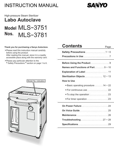
30.10.2014
•
Views
Share
Embed
Flag
MLS-3781L Instructions Manual — Medical
MLS-3781L Instructions Manual — Medical
SHOW MORE
SHOW LESS
ePAPER READ
DOWNLOAD ePAPER
- TAGS
- sterilization
- exhaust
- display
- digital
- cycle
- melting
- objects
- heating
- observe
- caution
- manual

s3.medicalproductsofamerica.com
You also want an ePaper? Increase the reach of your titles
YUMPU automatically turns print PDFs into web optimized ePapers that Google loves.
START NOW
-
More documents
-
Recommendations
-
Info


INSTRUCTION MANUAL High-pressure Steam Sterilizer Labo Autoclave Model Nos. <strong>MLS</strong>-3751 <strong>MLS</strong>-3781 Thank you for purchasing a Sanyo Autoclave. • Please read this instruction manual carefully before using the product. After reading this manual, store it in a readily accessible place along with the warranty card. • Please pay particular attention to the Safety Precautions section on page 1 to 6. Contents Page Safety Precautions . . . . . . . . . . . . . . . 1 ~ 6 Precautions in Use . . . . . . . . . . . . . . . . . . . 7 Before Using the Product . . . . . . . . . . . . . . 8 Names and Functions of Part . . . . . . . 9 ~ 10 Explanation of Label . . . . . . . . . . . . . . . . . 11 Sterilization Objects . . . . . . . . . . . . . 12 ~ 13 Model No. indication How to Use • Basic operating procedure . . . . . . 14 ~ 22 • For continuous use . . . . . . . . . . . . . . . 22 • To stop the operation . . . . . . . . . . . . . . 23 • For timer operation . . . . . . . . . . . . . . . . 23 On Power Failure . . . . . . . . . . . . . . . . . . . . 24 On Voice Guide . . . . . . . . . . . . . . . . . . . . . 25 Maintenance . . . . . . . . . . . . . . . . . . . . . . . . 26 Troubleshooting . . . . . . . . . . . . . . . . 27 ~ 28 Specifications . . . . . . . . . . . . . . . . . . . . . . 29
- Page 2 and 3: Safety Precautions These precaution
- Page 4 and 5: Safety Precautions WARNING Do not s
- Page 6 and 7: Safety Precautions CAUTION Be caref
- Page 8 and 9: Precautions in Use Use purified or
- Page 10 and 11: Names and Functions of Parts Rear s
- Page 12 and 13: Explanation of Labels Rating label
- Page 14 and 15: Sterilization Objects Sterilization
- Page 16 and 17: How to Use 1. Install the exhaust t
- Page 18 and 19: How to Use 4. Pour the heating wate
- Page 20 and 21: How to Use 8. Change the settings
- Page 22 and 23: How to Use To stop operation See pa
- Page 24 and 25: How to Use To stop the operation 1)
- Page 26 and 27: On Voice Guide The voice guide of t
- Page 28 and 29: Troubleshooting If any trouble aris
- Page 30 and 31: Specifications Product Designation
- Page 32: 3RF6P10304500 SANYO Electric Co., L
Delete template?
Are you sure you want to delete your template?
Save as template?
Title
Description
no error
![]()
products
- FREE
- adFREE
- WEBKiosk
- APPKiosk
- PROKiosk
Resources
- Blog
- API
- Help & Support
- Status
- tuxbrain.com
- ooomacros.org
- nubuntu.org
Company
- Contact us
- Careers
- Terms of service
- Privacy policy
- Cookie policy
- Cookie settings
- Imprint
Terms of service
Privacy policy
Cookie policy
Cookie settings
Imprint
![]() Change language
Change language
Made with love in Switzerland
© 2023 Yumpu.com all rights reserved
I
FILE No.
SERVICE MANUAL
High-pressureSleamSlerilizer
Labo Autoclave
MODEL NO.
MLS-37S1 Ll3781 L
Photo: MLS-3751 L
INDEX
~—
ITEM NAME PLATE
• Model No.indication
R»»N,r:; LABEL
+Model No. and rated power
supply voltage are indicated here.
Model No.
Rated
Voltage
Plug
MLS·3751L
AC 120V
MLS·3751L
AC230V
MLS·3781L
AC230V
MLS·3781L
AC230V
Productcord No.
131699501
131699502
131699401
131699402
1. Safety Precautions in Servicing Work ……………………………………………. ·············1
2. Specifications ……………………………………………… ·········································2
3. Outside Dimensions ………………………….•………..•………..•……………………… 3″»»4
4. Names of Parts and Operations ……………………………………………… ··············5-6
5. Construction and Functions …………………………………………………………….. 7 . . . . . . . . . . 10
6. Piping Diagram and Wiring Diagram ………..•………..•………..•………………
·····11~12
7. Process Flow and Operations …………………………………………………………
··13~21
8. About Various Modes
.. · .. · .. · .. · .. · .. · .. · .. · .. · .. · .. · .. · .. · .. · .. · .. · .. ···· .. · .. · …. · .. · .. · .. ·· .. 22 . . . . . . . . . . 27
9. Temperature and Pressure Adjustment and Checking ……………………………… ··28 . . . . . . . . . . 32
10. Thermistor Temperature Characteristics /
Altitude. Atmospheric Pressure and Boiling Point in Standard Atmosphere················ 33
11. Circuit Diagram ……………………………………………… ······································34
12. Troubleshooting ………………………………………………
································35~44
13. Disassembling Procedure ………….•………..•………..•………..•………………….
··45~50
14. Instruction Manual .. · .. · .. · .. · .. · .. · .. · .. · .. · .. · .. · .. · .. · .. · .. · .. · .. · .. · .. · .. · .. · …. · .. · .. · .. ·· .. 51 . . . . . . . . . . 63
15. Parts List ……………………………………………….•………..•………………….
··64~71
16. Instruction Manual of
Works
for Optional Parts ··· .. · .. · .. · .. · .. · .. · .. · .. · …. · .. · .. · .. ·· .. 72 . . . . . . . . . . 79
REFERENCE No. SM6610004
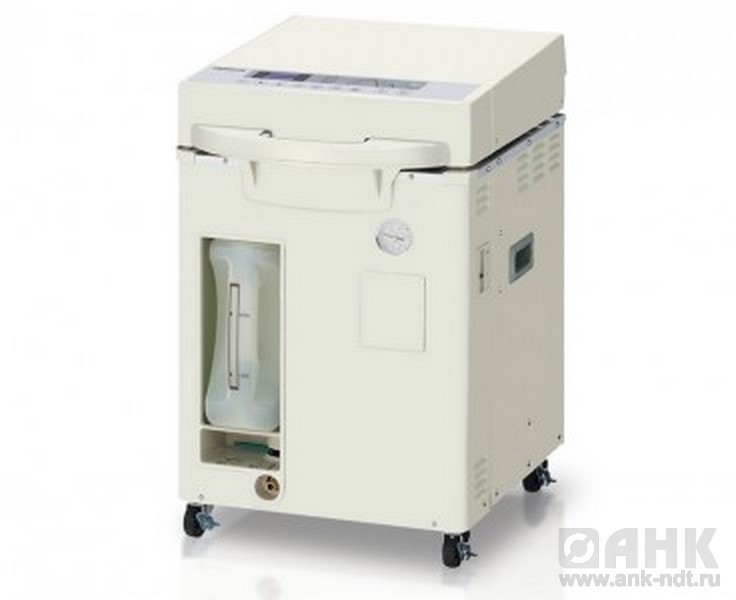
Наличие уточняйте у менеджера
![]()
Уточнить наличие
Нашли дешевле? Снизим цену!

Доставка в г. Ростов-на-Дону

Самовывоз
Малиновского ул., 3

Время доставки
от 2-х дней при наличии на складе
Наши преимущества

Бесплатная доставка
по всей территории России

Гарантия низкой цены
на все оборудование

Гарантия производителя
от 1 года до 5 лет

Официальный дилер
в наличии все сертификаты
Описнание автоклава SANYO MLS-3781L (75 литров)
Автоклав с вертикальной загрузкой SANYO (Panasonic) MLS-3781L поставляется на территорию России компанией АналитПромПрибор. Автоклав является автономным устройством с простым управлением, которое обеспечивает надежую и безопасную стерилизацию паром под давлением. Этот надежный и экономичный автоклав подходит для использования в самых разных областях.
Преимущества
— Большая вместимость камеры.
— Удобный доступ к образцам.
— Микропроцессорный контроль.
— Надежный в эксплуатации.
— Компактный дизайн.
— Низкое потребление электроэнергии.
— Эргономичный дизайн.
Автоклавы MLS-3781L – это автоматические программируемые вертикальные автоклавы, оснащенные системой микропроцессорного контроля.
Микропроцессорное управление автоклава гарантирует точное поддержание заданной температуры, регулируемый температурный диапазон составляет от 105 °C до 135 °C.
В этом диапазоне точность контроля установленной температуры составляет +2°C/-0°C.
Автоклавы MLS-3781L удобно эксплуатировать, они занимают небольшую площадь в лаборатории, корзины для стерилизации удобно загружать и выгружать.
Камера автоклава имеет диаметр 370 мм и рассчитана на три корзины для стерилизации, при этом в одной корзине размещаются 4 колбы объемом 1000 мл.
В одной корзине также могут быть расположены два 50-местных штатива для пробирок.
Верхняя крышка на петлях откидывается вверх, упрощая доступ к камере и стерилизационным корзинам.
Для удобства работы оператора контрольная панель расположена сверху.
Резервуар для воды легко заполнять, сливной шланг оснащен защелкой.
Для стерилизации, а также приготовления и поддержания культуральных сред предусмотрены 4 основных программы (каждая программа имеет 3 разновидности):программа стерилизации жидкостей,программа плавления/поддержания в нагретом состоянии,программа стерилизации/поддержания в нагретом состоянии, программа стерилизации стекла и др. лабораторного оборудования.
Технические характеристики автоклава SANYO (Panasonic) MLS-3781L (75 литров):
|
Модель |
MLS 3781L |
|
Тип |
вертикальный, программируемый, автоматический |
|
Полезный объем, л |
75 |
|
Размеры камеры, мм |
370х630 |
|
Внешние размеры, мм |
478х632х965 |
|
Вес, кг |
71 |
|
Температура стерилизации |
От 105° до 135°C |
|
Температура плавления культуральных сред |
От 60° до 100°C |
|
Мощность, кВт |
4 |
|
Электроподключение |
230 В, 50 Гц |
|
Максимальное давление |
0,235 МПа |
|
Поддержание теплой температуры |
От 45° до 60°C |
|
Таймер стерилизации |
От 1 до 250 мин, программа стерилизации инструментов до 72 ч |
|
Таймер плавления |
От 0 до 250 мин, (расширение до 72 ч) |
|
Таймер поддержания температуры |
Задержка до 72 ч, автоматическое выключение |
|
Программный таймер |
От 1 до 99 ч |
|
Материал камеры |
нержавеющая сталь SUS404 |
|
Системы безопасности |
Клапан безопасности давления, предохраняющее от ожогов покрытие, защита от перегрева, ограничитель давления, дверной замок, плавкий предохранитель |
|
Аксессуары |
Корзины из нержавеющей стали, 3 шт. |
Автоклав с вертикальной загрузкой SANYO (Panasonic) MLS-3781L поставляется на территорию России компанией АналитПромПрибор. Автоклав является автономным устройством с простым управлением, которое обеспечивает надежую и безопасную стерилизацию паром под давлением. Этот надежный и экономичный автоклав подходит для использования в самых разных областях.
Преимущества
— Большая вместимость камеры.
— Удобный доступ к образцам.
— Микропроцессорный контроль.
— Надежный в эксплуатации.
— Компактный дизайн.
— Низкое потребление электроэнергии.
— Эргономичный дизайн.
Автоклавы MLS-3781L – это автоматические программируемые вертикальные автоклавы, оснащенные системой микропроцессорного контроля.
Микропроцессорное управление автоклава гарантирует точное поддержание заданной температуры, регулируемый температурный диапазон составляет от 105 °C до 135 °C.
В этом диапазоне точность контроля установленной температуры составляет +2°C/-0°C.
Автоклавы MLS-3781L удобно эксплуатировать, они занимают небольшую площадь в лаборатории, корзины для стерилизации удобно загружать и выгружать.
Камера автоклава имеет диаметр 370 мм и рассчитана на три корзины для стерилизации, при этом в одной корзине размещаются 4 колбы объемом 1000 мл.
В одной корзине также могут быть расположены два 50-местных штатива для пробирок.
Верхняя крышка на петлях откидывается вверх, упрощая доступ к камере и стерилизационным корзинам.
Для удобства работы оператора контрольная панель расположена сверху.
Резервуар для воды легко заполнять, сливной шланг оснащен защелкой.
Для стерилизации, а также приготовления и поддержания культуральных сред предусмотрены 4 основных программы (каждая программа имеет 3 разновидности):программа стерилизации жидкостей,программа плавления/поддержания в нагретом состоянии,программа стерилизации/поддержания в нагретом состоянии, программа стерилизации стекла и др. лабораторного оборудования.
Технические характеристики автоклава SANYO (Panasonic) MLS-3781L (75 литров):
| Модель | MLS 3781L |
| Тип | вертикальный, программируемый, автоматический |
| Полезный объем, л | 75 |
| Размеры камеры, мм | 370х630 |
| Внешние размеры, мм | 478х632х965 |
| Вес, кг | 71 |
| Температура стерилизации | От 105° до 135°C |
| Температура плавления культуральных сред | От 60° до 100°C |
| Мощность, кВт | 4 |
| Электроподключение | 230 В, 50 Гц |
| Максимальное давление | 0,235 МПа |
| Поддержание теплой температуры | От 45° до 60°C |
| Таймер стерилизации | От 1 до 250 мин, программа стерилизации инструментов до 72 ч |
| Таймер плавления | От 0 до 250 мин, (расширение до 72 ч) |
| Таймер поддержания температуры | Задержка до 72 ч, автоматическое выключение |
| Программный таймер | От 1 до 99 ч |
| Материал камеры | нержавеющая сталь SUS404 |
| Системы безопасности | Клапан безопасности давления, предохраняющее от ожогов покрытие, защита от перегрева, ограничитель давления, дверной замок, плавкий предохранитель |
| Аксессуары | Корзины из нержавеющей стали, 3 шт. |
Дополнительные материалы
Загруженных файлов нет
Как купить?
Сделать заказ через интернет-магазин в нашем каталоге продукции
В течение рабочего дня Вам будет выставлен счет на оплату, в котором будет указано наименование
товара, цена, количество и срок отгрузки в Ваш адрес.
Направить нам заявку по электронной почте, указанной на странице
выбранного Вами товара.
В заявке необходимо указать наименование и количество нужного Вам товара, а также реквизиты
организации плательщика.
Посетить наш офис, сделать заявку и получить счет на оплату в отделе
продаж
В выставочном зале Вы можете ознакомиться с предлагаемыми нами оборудованием, а технические
специалисты помогут Вам выбрать нужную продукцию.
Доставка
Мы имеем возможность доставки товара в любую точку России, интересующей транспортной компанией или
курьерской службой:
Товар можно доставить как до терминала транспортной компании, так и, непосредственно, до двери.
Стоимость доставки рассчитывается специалистами логистической службы нашей компании в кратчайшие
сроки
в необходимое место по желанию заказчика.
Уточнить условия и стоимость доставки Вы можете, связавшись со специалистами нашей компании.
Оплата
Юридическим лицам
С юридическими лицами отношения регламентируются договором, счетом на оплату, товарной накладной,
счет-фактурой (УПД) и безналичным переводом денежных средств из банка Покупателя на расчетный счет
Продавца.
Физическим лицам
Физическое лицо также может произвести оплату на наш расчетный счет банковским переводом или
наличными средствами. При получении товара передается пакет документов: оригинал счета на оплату
продукции, товарная накладная и счет-фактура (УПД).
Похожие товары
Наши услуги
Узнайте цену
Для получения цены заполните форму, наши менеджеры обязательно с Вами свяжутся
Уточнить наличие
Для уточнения наличия заполните форму, наши менеджеры обязательно с Вами свяжутся
Получить скидку в компании «АНК»
Для получения скидки заполните форму, наши менеджеры обязательно с Вами свяжутся
Задать вопрос специалистам компании «АНК»
Задайте вопрос по интересующему Вас оборудованию и в ближайшее время наши специалисты с Вами свяжутся.
Остались вопросы?
Получите бесплатную консультацию у наших менеджеров!


MLS-3751L
MLS-3781L
Top-Loading
Portable
Autoclaves
Features:
•Compact, portable design allows for models to conveniently be moved from one lab to another.
•Delivers high pressure steam with speed, efficiency and reliability
Panasonic… the new name for SANYO
www.panasonic.com/biomedical
 Loading…
You can only view or download manuals with
Sign Up and get 5 for free
Upload your files to the site. You get 1 for each file you add
Get 1 for every time someone downloads your manual
Buy as many as you need