- Manuals
- Brands
- baltur Manuals
- Burner
- BTG 15P
- Instructions manual
-
Bookmarks
Quick Links
— Istruzioni per bruciatori modello
— Instruction for burners model
— Instrucciónes para quemadores modelos
— Mode d’emploi bruleûr
IT-GB-SP-FR
IT-GB-SP-FR
BTG 15P
BTG 20P
BTG 28P
0006080895_200702
0006080895_200702
Related Manuals for baltur BTG 15P
Summary of Contents for baltur BTG 15P
-
Page 1
IT-GB-SP-FR IT-GB-SP-FR — Istruzioni per bruciatori modello BTG 15P — Instruction for burners model BTG 20P — Instrucciónes para quemadores modelos — Mode d’emploi bruleûr BTG 28P 0006080895_200702 0006080895_200702… -
Page 3
IT — Prima di iniziare a usare il bruciatore leggere attentamente quanto esposto nell’ouscolo “AVVERTENZE PER L’UTENTE, PER L’USO IN SICUREZZA DEL BRUCIATORE” presente a corredo del manuale istruzioni, che costituisce parte integrante ed essenziale del prodotto. — Leggere attentamente le istruzioni prima di mettere in funzione il bruciatore o di eseguire la manutenzione. -
Page 4
Dichiarazione di Conformità Statement of Conformity Statement of Conformity Dichiariamo, sotto la Nostra responsabilità, hereby declare under che i Nostri prodotti contrassegnati “CE” responsibility, that our “CE” marked products Serie: Series: Sparkgas…; BTG…; BGN…; TBG…; Sparkgas…; BTG…; BGN…; TBG…; Minicomist…; Comist…; RiNOx…, BT…; Minicomist…;… -
Page 5
Declaración de Conformidad Déclaration de conformité Declaramos bajo nuestra responsabilidad Nous déclarons, sous notre responsabilité, que nuestros productos identifi cados con el que nos produits portant la marque “CE” marcado “CE” Serie: Séries : Sparkgas…; BTG…; BGN…; TBG…; Sparkgas…; BTG…; BGN…; TBG…; Minicomist…;… -
Page 6
INDICE / INDEX / ÍNDICE / SOMMAIRE INDICE / INDEX / ÍNDICE / SOMMAIRE ITALIANO ———————————————————————————————————————————————————————17 AVVERTENZE PER L’UTENTE PER L’USO IN SICUREZZA DEL BRUCIATORE ————————————————————————-6 CARATTERISTICHE TECNICHE — CAMPO DI LAVORO ———————————————————————————————————14 APPLICAZIONE DEL BRUCIATORE ALLA CALDAIA — DESCRIZIONE DEL FUNZIONAMENTO —————————————————-17 ACCENSIONE E REGOLAZIONE A GAS METANO —————————————————————————————————————18 REGOLAZIONE DELL’ARIA SULLA TESTA DI COMBUSTIONE ———————————————————————————————19 REGOLAZIONE COMBUSTIONE — SCHEMA REGOLAZIONE TESTA DI COMBUSTIONE ————————————————————20… -
Page 7
INDICE / INDEX / ÍNDICE / SOMMAIRE INDICE / INDEX / ÍNDICE / SOMMAIRE ESPAÑOL ———————————————————————————————————————————————————————51 ADVERTENCIAS DIRGIDAS AL USUARIO ————————————————————————————————————————-10 CARACTERISRICAS TECNICAS —————————————————————————————————————————————14 APLICACIÓN DEL QUEMADOR A LA CALDERA — DESCRIPCIÓN DEL FUNCIONAMIENTO ——————————————————-51 ENCENDIDO Y REGULACIÓN CON GAS NATURAL ————————————————————————————————————52 REGULACIÓN DEL AIRE EN EL CABEZAL DE COMBUSTIÓN — REGULACIÓN DE LA COMBUSTIÓN ——————————————53 REGULACIÓN DEL CABEZAL DE COMBUSTIÓN — ESQUEMA DE DISPOSICIÓN DE LOS ELECTRODOS ————————————54 ESQUEMA DE MONTAJE DEL VENTILADOR — USO DEL QUEMADOR ———————————————————————————-56… -
Page 8
Rivolgersi esclusivamente a personale professionalmente qualifi cato. L’eventuale riparazione dei prodotti dovrà essere effettuata solamente da un centro di assistenza autorizzato dalla BALTUR utilizzando esclusivamente ricambi originali. Il mancato rispetto di quanto sopra, può BALTUR utilizzando esclusivamente ricambi originali. Il mancato rispetto di quanto sopra, può… -
Page 9
AVVERTENZE PER L’UTENTE PER L’USO IN SICUREZZA DEL BRUCIATORE ALIMENTAZIONE ELETTRICA • La sicurezza elettrica dell’apparecchio è raggiunta soltanto quando lo stesso è corretamente collegato a un’effi cace impianto di messa a terra, eseguito come previsto dalle vigenti norme di sicurezza. E’ necessario verifi care questo fondamentale requisito di sicurezza. In caso di dubbio, richiedere un controllo accurato dell’impianto elettrico da parte di personale professionalmente qualifi… -
Page 10
• If there is any fault or if the equipment is not working properly, de-activate the equipment and do not attempt to repair it or tamper with it directly. In such case get in touch with only qualifi ed technicians. Any product repairs must only be carried out by BALTUR authorised assistance centres using only original spare parts. -
Page 11
WARNING NOTES FOR THE USER HOW TO USE THE BURNER SAFELY ELECTRICAL SUPPLY • The equipment is electrically safe only when it is correctly connected to an effi cient ground connection carried out in accordance with current safety regulations. It is necessary to check this essential safety requirement. If in doubt, call for a careful electrical check by a qualifi ed technicians, since the manufacturer will not be liable for any damage caused by a poor ground connection. -
Page 12
Diríjase exclusivamente a personal cualifi cado profesionalmente. La eventual reparación de los aparatos tiene que hacerla solamente un centro de asistencia autorizado por BALTUR utilizando exclusivamente repuestos originales. Si no se respeta lo anteriormente se puede comprometer la seguridad del aparato. Para garantizar la efi cacia del aparato y para que funcione correctamente es indispensable que el personal cualifi… -
Page 13
ADVERTENCIAS DIRIGIDAS AL USUARIO PARA USAR EL QUEMADOR EN CONDICIONES DE SEGURIDAD PRELIMINARES QUEMADOR EN CONDICIONES DE SEGURIDAD PRELIMINARES ALIMENTACIÓN ELÉCTRICA • La seguridad eléctrica del aparato se consigue solo cuando el mismo está conectado correctamente a una buena instalación de puesta a tierra, realizado tal y como establecen las normas de seguridad vigentes. -
Page 14
S’adresser exclusivement à du personnel professionnellement qualifi é. L’éventuelle réparation des produits doit être effectuée par un centre de service après-vente agréé par BALTUR en utilisant exclusivement des pièces détachées d’origine. Le non-respect de cette recommandation peut compromettre la sécurité de l’appareil. Pour garantir l’effi cience de ce dernier et pour que son fonctionnement soit correct, il est indispensable de faire effectuer l’entretien périodique par du personnel professionnellement qualifi… -
Page 15
RECOMMANDATIONS A L’ATTENTION DE L’UTILISATEUR POUR UN USAGE DU BRULEUR EN TOUTE SECURITE INTRODUCTION ALIMENTATION ELECTRIQUE • La sécurité électrique de l’appareil est atteinte uniquement lorsque ce dernier est correctement raccordé à une installa- tion de mise à la terre effi cace, exécutée comme prévu par les normes de sécurité en vigueur. Cette condition requise de sécurité… -
Page 16
CARATTERISTICHE TECNICHE / TECHNICAL DATA / CARACTERISTIQUES TECHNIQUES / CARACTERISTICAS TECNICAS BTG 15P BTG 20P BTG 28P PORTATA GAS NATURALE / NATURAL GAS FLOW RATE / 16,1 20,6 28,2 CAUDAL GAS NATURAL / DEBIT GAZ NATUREL / PORTATA G.P.L. / L.P.G. FLOW RATE / CAUDAL GPL / DÉBIT GPL… -
Page 17
CARATTERISTICHE TECNICHE / TECHNICAL DATA / CARACTERISTIQUES TECHNIQUES / CARACTERISTICAS TECNICAS CAMPO DI LAVORO / OPERATING RANGE / CAMPO DE TRABAJO / N° 0002922481 PLAGE D’ULISATION Rev.16/11/2006 — Nota: I campi di lavoro sono stati ottenuti in conformità alle Normative EN 676 — The work fi… -
Page 18
CARACTERISTIQUES TECHNIQUES / CARACTERISTICAS TECNICAS N° 0002470992 Rev.24/08/2006 MOD. min max Ø Ø min max BTG 15P 303 150 280 126 114 135 M10 170 210 BTG 20P 303 150 300 127 114 135 M10 170 210 BTG 28P 303 150 300… -
Page 19
BRUCIATORE DI GAS BISTADIO N° 0002934100 APPLICAZIONE DEL BRUCIATORE ALLA CALDAIA Rev. 10/02/2004 La tubazione di adduzione gas deve essere dimensionata in funzione della lunghezza e della erogazione di gas secondo norma UNI; deve essere perfettamente ermetica ed adeguatamente provata prima del collaudo del bruciatore. -
Page 20
BRUCIATORE DI GAS BISTADIO ACCENSIONE E REGOLAZIONE A GAS METANO (per l’utilizzo di gas GPL vedere l’apposito capitolo) Per procedere all’accensione occorre verifi care, se il bruciatore è trifase, che il senso di rotazione del motore sia corretto. E’ indispensabile, se non è già stato fatto all’atto del collegamento del bruciatore alla tubazione del gas, con le cautele del caso e con porte e fi… -
Page 21
N.B. Per agevolare la regolazione della testa di combustione, si consiglia di vedere le tabelle ( dis. 0002935000 per BTG 15P, dis. 0002934171 per BTG 20P e dis. 0002935180 per BTG 28P). Riducendo il passaggio dell’aria sulla testa di combustione, occorre evitarne la chiusura completa che potrebbe determinare un eccessivo riscaldamento della testa con conseguente rapido deterioramento. -
Page 22
(0 = MIN 3 = MAX per BTG 20P) (0 = MIN 4 = MAX per BTG 28P) N° 0002935000 SCHEMA REGOLAZIONE TESTA DI COMBUSTIONE BTG 15P Rev.25/08/2006 X = Distanza testa/disco. Min. Max. BTG 15P 20 / 88 0006080895 ed 2007/02… -
Page 23
BRUCIATORE DI GAS BISTADIO N° 0002934171 SCHEMA REGOLAZIONE TESTA DI COMBUSTIONE BTG 20P Rev.22/10/2004 Entrata gas Elettrodo accensione Flangia attacco caldaia X = Distanza testa/disco. Min. Max. BTG 20P X = Distanza testa/disco. NOTA: Diminuendo la distanza “X” diminuisce il valore di emissione di NOx. -
Page 24
BRUCIATORE DI GAS BISTADIO SCHEMA DISPOSIZIONE ELETTRODI BTG 15P — BTG 20P — BTP 28P Elettrodo ionizzatore Elettrodo accensione Disco fi amma Miscelatore Tubo mandata gas BTG 15P BTG 20P 2÷3 BTG 28P 2÷3 N° 0002934540 SCHEMA DI MONTAGGIO VENTOLA Rev.04/04/2005… -
Page 25
BRUCIATORE DI GAS BISTADIO MANUTENZIONE Il bruciatore non ha bisogno di particolare manutenzione, sarà comunque bene controllare periodicamente che il fi ltro del gas sia pulito e l’elettrodo di ionizzazione effi ciente. Occorre anche verifi care che la scintilla dell’elettrodo di accensione avvenga esclusivamente tra tra lo stesso ed il disco di lamiera forata.Può… -
Page 26
BRUCIATORE DI GAS BISTADIO APPARECCHIATURA DI COMANDO E CONTROLLO PER BRUCIATORI A GAS LME 21… Diagramma di collegamento e sequenza di controllo LME 21 Diagramma di collegamento e sequenza di controllo LME 21 (quando si utilizza in collegamento con degli attuatori, è necessario osservare i requisiti EN 676) Legenda Trasformatore per l’accensione Messaggio di errore (allarme) -
Page 27
BRUCIATORE DI GAS BISTADIO APPARECCHIATURA DI COMANDO E CONTROLLO PER BRUCIATORI A GAS LME 21… Indicazione Durante l’avviamento, l’indicazione dello stato avviene secondo la seguente tabella: stato operativo Tabella codici colore per indicatore luminoso multicolore (LED) Stato Stato Stato Stato Codice colore Codice colore Codice colore… -
Page 28
BRUCIATORE DI GAS BISTADIO APPARECCHIATURA AUTOMATICA DI CONTROLLO PER BRUCIATORI A GAS mono o bistadio a fl usso forzato SCHEMA CIRCUITI E DI TEMPORIZZAZIONE DLG 976 Descrizione Interruttore principale Interruttore controlo aria Interruttore controllo gas Segnale di blocco esterno Termostato limite max. -
Page 29
BRUCIATORE DI GAS BISTADIO Visualizzazione della sequenza di programmazione Il microprocessore incorporato controlla non solo la sequenza di programmazione ma anche il sistema informativo. Le singole fasi della sequenza di programmazione vengono visualizzate sotto forma di codice di lampeggio. E’ possibile distinguere i seguenti messaggi: Attesa messaggio Codice lampeggio per interr. -
Page 30
BRUCIATORE DI GAS BISTADIO Blocco e risettaggio L’unità può essere risettata o bloccata in due modi diversi: Interno In caso di blocco l’unità può essere risettata premendo il pulsante incorporato. Viene così eseguito un nuovo ciclo di avviamento. Esterno Invece di utilizzare il pulsante di blocco incorporato è possibile ottenere la stessa funzione con un pulsante esterno che collega il terminale 9 ad A (vedere anche schema dei circuiti e schema a blocchi). -
Page 31
BRUCIATORE DI GAS BISTADIO N° 0002910311 VALVOLA GAS COMBINATA DUNGS (monoblocco) REV.:13/01/2004 MOD. MB-ZRDLE…B01 collegamenti elettrici collegamenti elettrici presa di pressione in uscita valvola presa di pressione in uscita valvola fl angia uscita senso del fl usso senso del fl usso fl… -
Page 32
BRUCIATORE DI GAS BISTADIO VALVOLA GAS COMBINATA DUNGS N° 0002910311 (monoblocco) MOD. MB-ZRDLE…B01 REV.:13/01/2004 Il monoblocco DUNGS modello MB-ZRDLE..è costituito da: a) Pressostato di minima pressione gas (3) b) Filtro gas (6) c) Regolatore (stabilizzatore) di pressione (2) d) Valvola di sicurezza (incorporata nel regolatore di pressione) ad apertura e chiusura rapida (4) e) Valvola principale a due posizioni (l°… -
Page 33
BRUCIATORE DI GAS BISTADIO PRECISAZIONI SULL’USO DEL PROPANO (G.P.L.) Riteniamo utile portare a Vostra conoscenza alcune considerazioni circa l’uso del gas liquido propano (G.P.L.). 1) Valutazione, indicativa, del costo di esercizio a) 1 m di gas liquido in fase gassosa ha un potere calorifi co inferiore, di circa 22.000 kcal. b) Per ottenere 1 m di gas occorrono circa 2 kg di gas liquido che corrispondono a circa 4 litri di gas liquido. -
Page 34
BRUCIATORE DI GAS BISTADIO BT 8721/2 SCHEMA DI PRINCIPIO PER RIDUZIONE PRESSIONE GPL A DUE SALTI PER BRUCIATORE OPPURE CALDAIA REV. 26/05/2004 PRESSOSTATO ARIA Eseguire la regolazione del pressostato aria dopo aver effettuato tutte le altre regolazioni del bruciatore con il pressostato aria regolato a inizio scala. -
Page 35
IRREGOLARITÀ DI FUNZIONAMENTO IRREGOLARITA IRREGOLARITA IRREGOLARITA IRREGOLARITA CAUSA POSSIBILE CAUSA POSSIBILE CAUSA POSSIBILE CAUSA POSSIBILE RIMEDIO RIMEDIO RIMEDIO RIMEDIO Il bruciatore non si avvia. 1) Mancanza di energia 1) Controllare i fusibili della linea di alimentazio- elettrica. ne. Controllare i fusibili dell’apparecchiatura elettrica. -
Page 36
TWO-STAGE GAS BURNERS N° 0002934100 INSTALLING ON BOILER Rev. 10/02/2004 The di mensions of the gas adduction pipeline should be in function with it’s length and with gas delivery according to UNI re gu la tions; It must be per fe ctly hermetic and ade qua tely tested be fore the burner is general in spection. It is indispensable to install a suitable pi pe union in the pipeline, in proximity to the burner, to allow for easy di sas- sembly of the burner and opening of the boiler door. -
Page 37
TWO-STAGE GAS BURNERS NATURAL GAS STARTING UP AND REGULATION (for LPG operation see the relative chapter) In order to proceed with starting up, it’s necessary, if the burner is three-phase, to check that the sense of rotation of the motor is correct. If not already done so at the moment of connecting the burner to the gas pipeline, it’s indi- spensable to carry a purge of the air contained in the pipeline. -
Page 38
(0002934190) so as to have a suitable air fl ow for the output, with suction air regulation damper sensibly open. N.B. To facilitate the combustion head regulation, see tables (n° 0002935000 for BTG 15P, 0002934171 for BTG 20P and 0002935180 for BTG 28P). -
Page 39
TWO-STAGE GAS BURNERS N° 0002935000 COMBUSTION HEAD ADJUSTMENT DIAGRAM BTG 15P Rev.25/08/2006 Gas inlet Ignition electrode Ignition electrode Burner fi xing fl ange Burner fi xing fl ange X = Disk / head distance Min. Max. BTG 15P N° 0002934171 COMBUSTION HEAD ADJUSTMENT DIAGRAM BTG 20P Rev.22/10/2004… -
Page 40
Gas inlet Ignition electrode X = Disk / head distance. Burner fi xing fl ange Min. Max. BTG 28P BTG 15P — BTG 20P ELECTRODES ADJUSTMENT DIAGRAM Ionisation electrode Ignition electrode Flame disk Gas diffuser Gas delivery pipe BTG 15P BTG 20P 2÷3… -
Page 41
TWO-STAGE GAS BURNERS BTG 28P ELECTRODES ADJUSTMENT DIAGRAM Ionisation electrode Ignition electrode Flame disk Gas diffuser Gas delivery pipe BTG 28P 2÷3 N° 0002934540 FAN ASSEMBLY DIAGRAM Rev.04/04/2005 — Observe the measurements indicated in the diagram when fi tting the fan. USE OF THE BURNER The burner operates fully automatically, therefore it is non necessary to carry out any kind at adjustment during its operating. -
Page 42
TWO-STAGE GAS BURNERS MAINTENANCE The burner does not require special maintenance, but it is good practice to check periodically that the gas fi lter is clean and that the ignition electrode is effi cient. It is also necessary to verify that the ignition electrode’s spark is produced between the same electrode and the disk. -
Page 43
TWO-STAGE GAS BURNERS LME 21… GAS BURNER CONTROL DEVICE Legend Time Error message (alarm) Limit thermostat / pressure switch Unit fuse Ignition transformer BV… Fuel valve Start command (switching on by «R») EK… Remote lockout reset button (inter- B-B´ Interval for establishment of fl ame nal) Operating position of burner reached Ionization probe… -
Page 44
TWO-STAGE GAS BURNERS GAS BURNER CONTROL DEVICE GAS LME 21… Operational status During startup, status indication takes place according to the following table: indication Color code table for multicolor signal lamp (LED) Status Color code Color Waiting time «tw», other waiting states …….. -
Page 45
TWO-STAGE GAS BURNERS GAS BURNER SAFETY CONTROL CIRCUIT AND TIMING DIAGRAM DLG 976 Description Mains switch Solenoid valve, 2 -stage Gas proving switch Air proving switch Limit thermostat External lock out signal Control thermostat max. reaction time for air proving switch External reset and lock out button Supervised pre-purge time Ionisation probe… -
Page 46
TWO-STAGE GAS BURNERS The built-in microprocessor controls not only the programming sequence but the information system too. The individual phases of the programming sequence are displayed as Flash-Code. The following messages can be distinguished: Message Flash-Code Description waiting for air proving switch I I . -
Page 47
TWO-STAGE GAS BURNERS Lock out and reset The unit can be reset or brought into lock out mode in two different ways: Internal In the lock out case the unit can be reset by pushing the built in button meaning a new start-up cycle is performed. -
Page 48
TWO-STAGE GAS BURNERS COMBINED DUNGS GAS VALVE (monobloc) N° 0002910311 MOD. MB-ZRDLE…B01 REV.:13/01/2004 electrical connections electrical connections pressure tap at valve exit pressure tap at valve exit exit fl ange fl ow direction fl ow direction entry fl ange plug pressure stabilizer pressure stabilizer bleed 1 Locking screw for 1st and 2nd fl… -
Page 49
TWO-STAGE GAS BURNERS COMBINED DUNGS GAS VALVE (monobloc) N° 0002910311 MOD. MB-ZRDLE…B01 REV.:13/01/2004 The monobloc DUNGS Model MB-ZRDLE is made up of: a) Minimum gas pressure switch (3) and maximum gas pressure (12) b) Gas fi lter (6) c) Pressure regulator (stabilizer) (2) d) Safety valve (incorporate in the pressure regulator) which opens and closes rapidly (4) e) Principle valve with two positions (lst fl… -
Page 50
TWO-STAGE GAS BURNERS NOTES ON USE OF PROPANE (L.P.G.) We think it would be useful to inform you on a few points regarding use of liquid propane gas (L.P.G.). 1) Approximate evaluation of running costs a) 1 m of liquid gas in gaseous state has heating power inferior by about 22.000 kcal. b) to obtain 1 m of gas about 2 kg of liquid gas are required. -
Page 51
TWO-STAGE GAS BURNERS N° 8721/2/GB GENERAL DIAGRAM FOR TWO-STAGE L.P.G. PRESSURE Rev. 21/03/90 REDUCTION FOR BURNER OR BOILER AIR PRESSURE SWITCH Regulate the air pressure switch after fi rst carrying out all the other burner adjustments with the air pressure switch adjusted to the start of the scale. With the burner operating at the requested power level, slowly turn the central screw clockwise until the burner locks out. -
Page 52
TWO-STAGE GAS BURNERS OPERATING ANOMALY TYPE OF IRREGULARITY TYPE OF IRREGULARITY TYPE OF IRREGULARITY TYPE OF IRREGULARITY PROBABLE CAUSE PROBABLE CAUSE PROBABLE CAUSE PROBABLE CAUSE RIMEDY RIMEDY RIMEDY RIMEDY The burner does not 1) Lack of currente. 1) Check the fuses of the feed line. Check the start. -
Page 53
QUEMADORES DE GAS NATURAL DE DOS ETAPAS APLICACIÓN DEL QUEMADOR A LA CALDERA La tubería de abastecimiento del gas tiene que estar dimensionada en función de la longitud y del suministro del gas según la norma UNI; y tiene que ser totalmente hermética y haber sido probada antes de la prueba de ensayo del quemador. -
Page 54
QUEMADORES DE GAS NATURAL DE DOS ETAPAS ENCENDIDO Y REGULACIÓN CON GAS NATURAL (para utilizar gas GPL véase el capítulo correspondiente) Antes de arrancar hay que verifi car que el quemador sea trifásico y que el sentido de rotación del quemador sea correcto. -
Page 55
NOTA: para facilitar la regulación del cabezal de combustión se aconseja consultar la tabla (ver diseño n° 0002935000 para BTG 15P — 0002934171 para BTG 20P y 0002935180 para BTG 28P). NOTA: controlar si el encendido se produce regularmente porque cuando el regulador se desplaza hacia adelante la velocidad del aire puede ser excesiva e impedir que el quemador se encienda. -
Page 56
QUEMADORES DE GAS NATURAL DE DOS ETAPAS N° 0002935000 REGULACIÓN DEL CABEZAL DE COMBUSTIÓN BTG 15P Rev.25/08/2006 Entrada del gas Electrodo de encendido Arandela de conexión a la caldera = Distancia cabezal/disco = Distancia cabezal/disco Min. Max. BTG 15P N° 0002934171 REGULACIÓN DEL CABEZAL DE COMBUSTIÓN BTG 20P… -
Page 57
Electrodo de encendido X = Distancia cabezal/disco Arandela de conexión a la caldera Min. Max. BTG 28P ESQUEMA DE DISPOSICIÓN DE LOS ELECTRODOS BTG 15P — BTG 20P Electrodo ionizador Electrodo de encendido Disco llama Mezclador Tubo de salida del gas… -
Page 58
QUEMADORES DE GAS NATURAL DE DOS ETAPAS ESQUEMA DE DISPOSICIÓN DE LOS ELECTRODOS BTG 28P Electrodo ionizador Electrodo de encendido Disco llama Mezclador Tubo de salida del gas BTG 28P 2÷3 N° 0002934540 ESQUEMA DE MONTAJE DEL VENTILADOR Rev.04/04/2005 Verifi car durante la fase de montaje del ventilador que se respete la medida indicada en la fi… -
Page 59
QUEMADORES DE GAS NATURAL DE DOS ETAPAS MANTENIMIENTO El quemador no necesita un mantenimiento especial, pero es aconsejable que se controle periódicamente que el fi ltro del gas esté limpio y que el electrodo de ionización sea efi ciente. Hay que verifi car también que la chispa del electrodo de encendido se dé… -
Page 60
QUEMADORES DE GAS NATURAL DE DOS ETAPAS CONTROL DE SEGURIDAD PARA QUEMADORE DE GAS LME 21… Diagrama de conexión y secuencia de control LME 21 Diagrama de conexión y secuencia de control LME 21 (cuando se utiliza en conexión con actuadores hay que respetar los requisitos EN 676) Leyenda Mensaje de error (alarma) Termostato de límite / presostato… -
Page 61
CAJAS DE MANDO Y CONTROL PARA QUEMADORES DE GAS LME 21… Indicación Durante la puesta en marcha, la indicación del estado tiene lugar según la tabla siguiente: del estado operativo Tabla de los códigos de color para el indicador luminoso multicolor (LED) Estado Código color Código color… -
Page 62
QUEMADORES DE GAS NATURAL DE DOS ETAPAS Control de Seguridad para Quemador de Gas CIRCUITO DE CABLEADO Y SECUENCIA DLG 976 Descrizione Interruptor principal Válvula solenoide 2da etapa Interruptor de prueba de gas Interruptor de fl ujo de aire limite Alarma Control Tiempo max. -
Page 63
QUEMADORES DE GAS NATURAL DE DOS ETAPAS Despliegue de secuencia de Programa El microprocesador incorporado controla la secuencia de programa y el sistema de información. Las fases individuales de la secuencia de programa es desplegada como un código de parpadeos. Mensaje Código de parpadeo Descripción… -
Page 64
QUEMADORES DE GAS NATURAL DE DOS ETAPAS Bloqueo y rearme La unidad puede ser rearmada o llevada a modo de bloqueo de dos formas diferentes: Interna En caso de bloqueo la unidad puede ser rearmada presionando el botón incorporado lo que hace que un nuevo ciclo de partida sea ejecutado. -
Page 65
QUEMADORES DE GAS NATURAL DE DOS ETAPAS VÁLVULA GAS COMBINADA (monobloque) N°0002910311 DUNGS MOD. MB-ZRDLE…B01 REV.13/01/2004 conexiones eléctricas conexiones eléctricas toma de presión a la salida de la válvula toma de presión a la salida de la válvula brida salida sentido del fl… -
Page 66
QUEMADORES DE GAS NATURAL DE DOS ETAPAS VÁLVULA GAS COMBINADA (monobloque) N°0002910311 DUNGS MOD. MB-ZRDLE…B01 REV.13/01/2004 El monobloque DUNGS modelo MB-ZRDLE… está formado por: a) Presóstato de mínima presión del gas (3) y máxima presión del gas (12) b) Filtro del gas (6) c) Regulador (estabilizador) de presión (2) (sólo para la versión B01) d) Válvula de seguridad (incorporada en el regulador de presión) de apertura y cierre rápido (4) e) Válvula principal con dos posiciones (1ª… -
Page 67
QUEMADORES DE GAS NATURAL DE DOS ETAPAS PUNTUALIZACIONES SOBRE EL USO DEL PROPANO (G.L.P.) Según nuestra opinión es útil poner en su conocimiento algunas consideraciones acerca del uso del gas líquido propano (G.L.P.). 1) ESTIMACIÓN INDICATIVA DEL COSTE DE UTILIZACIÓN a) 1 m de gas líquido en fase gaseosa tiene un poder calorífi… -
Page 68
QUEMADORES DE GAS NATURAL DE DOS ETAPAS N° BT 8721/2 ESQUEMA DE PRINCIPIO PARA REDUCIR LA PRESIÓN G.L.P. CON DOS SALTOS PARA QUEMADOR O PARA CALDERA Rev. 21/03/90 PRESOSTATO DEL AIRE Regular el presostato del aire tras haber realizado las demás regulaciones del quemador con el presostato del aire regulado al inicio de la escala. -
Page 69
QUEMADORES DE GAS NATURAL DE DOS ETAPAS IRREGULARIDADES EN EL FUNCIONAMIENTO DEFECTO DEFECTO DEFECTO CAUSA CAUSA CAUSA SOLUCIÓN SOLUCIÓN SOLUCIÓN El quemador no arranca. 1) Falta energía eléctrica. 1) Controlen los fusibles de la línea de alimenta- ción. Controlen los fusibles del programador. Controlen la línea de los termostatos y del presóstato del gas;… -
Page 70
BRÛLEUR GAZ NATUREL DEUX ALLURES N° 0002934100 APPLICATION DU BRULEUR A LA CHAUDIERE Rev. 10/02/2004 Le tuyau d’adduction gaz doit être de dimension adaptée à la longueur et à la distribution du gaz selon la norme UNI, il doit être parfaitement hermétique et testé avant la certifi cation de bon fonctionnement du brûleur. Sur ce tuyau, il est indispensable d’installer, à… -
Page 71
BRÛLEUR GAZ NATUREL DEUX ALLURES ALLUMAGE ET REGLAGE POUR LE GAZ NATUREL (en ce qui concerne l’utilisation de gaz GPL, consulter le chapitre approprié) Pour procéder à l’allumage, il est nécessaire de vérifi er, lorsque le brûleur est triphasé, que le sens de rotation du moteur soit correct. -
Page 72
N.B. Pour faciliter le réglage de la tête de combustion, il est conseillé de consulter le tableau (des. n° 0002935000 pour BTG 15P 0002934171 pour BTG 20P et 0002935180 pour BTG 28P). N.B. Contrôler que l’allumage s’effectue régulièrement car, en cas de déplacement du régulateur en avant; il se peut que la vitesse de l’air en sortie soit trop élevée, ce qui entraîne des diffi… -
Page 73
BRÛLEUR GAZ NATUREL DEUX ALLURES N° 0002935000 SCHEMA REGLAGE TETE DE COMBUSTION BTG 15P Rev.25/08/2006 Arrivée de gaz Arrivée de gaz Electrode d’allumage Distance tête/disque Bride de fi xation chaudière Min. Max. BTG 15P N° 0002934171 SCHEMA REGLAGE TETE DE COMBUSTION BTG 20P Rev.22/10/2004… -
Page 74
Arrivée de gaz Electrode d’allumage Distance tête/disque Bride de fi xation chaudière Min. Max. BTG 28P SCHEMA DISPOSITION DES ELECTRODES BTG 15P — 20P Electrode d’ionisation Electrode d’allumage Disque fl amme Mélangeur Tuyau de départ gaz BTG 15P BTG 20P 2÷3… -
Page 75
BRÛLEUR GAZ NATUREL DEUX ALLURES SCHEMA DISPOSITION DES ELECTRODES BTG 28P Electrode d’ionisation Electrode d’allumage Disque fl amme Mélangeur Tuyau de départ gaz BTG 28P 2÷3 N° 0002934540 SCHEMA DE MONTAGE VENTILATEUR Rev.04/04/2005 Lors de la phase de montage, vérifi er que la mesure indiquée sur la fi… -
Page 76
BRÛLEUR GAZ NATUREL DEUX ALLURES MANUTENTION Le brûleur ne nécessite pas d’entretien particulier, dans tous les cas, il convient de contrôler périodiquement que le fi ltre soit propre et l’électrode de ionisation en bon état. Il est aussi nécessaire que l’étincelle de l’électrode d’allumage ait lieu exclusivement entre celle-ci et le disque de tôle perforée. -
Page 77
BRÛLEUR GAZ NATUREL DEUX ALLURES BOÎTIER DE COMMANDE ET DE CÔNTROLE POUR BRÛLEUR À GAZ LME 21… Diagramme de branchement et séquence de contrôle LME 21 Diagramme de branchement et séquence de contrôle LME 21 (en cas de connexion avec des actionneurs, il est nécessaire de respecter les normes EN 676) Légende Message d’erreur (alarme) Temps… -
Page 78
BOÎTIER DE COMMANDE ET DE CÔNTROLE POUR BRÛLEUR À GAZ LME 21… Indication Durant le démarrage, l’indication de l’état s’effectue selon le tableau suivant : Tableau des codes couleur pour l’indicateur lumineux multicolore (LED) Etat Code couleur Code couleur Couleur Couleur Temps d’attente “tw”, autres états d’attente Eteint… -
Page 79
BRÛLEUR GAZ NATUREL DEUX ALLURES Coffret de contrôle automatique pour brûleurs au gaz SANS SERVOMOTEUR DE VOLET D’AIR DLG 976 Descrizione Electrovanne 2éme allure Interrupteur principal Contrôleur air Contrôleur gaz Voyant de dérangement externe Thermostat de sécurité Temps de réaction max. du contrôleur d’air Thermostat de régulation Temps de préventilation surveillé… -
Page 80
BRÛLEUR GAZ NATUREL DEUX ALLURES Signal de visualisation du programme Le microprocesseur contrôle non seulement le déroulement du programme, mais aussi le système d’information. Les différentes phases du programme peuvent être distinguées grâce à un code clignotant. Les messages suivants peuvent être distingués : Message Code clignotant Description… -
Page 81
BRÛLEUR GAZ NATUREL DEUX ALLURES Mise en dérangement et réarmement L’appareil peut être mis en dérangement ou réarmé de deux manières: Interne: En appuyant sur le bouton de réarmement lors d’une mise en dérangement, le coffret effectue un nouveau cycle de démarrage. -
Page 82
BRÛLEUR GAZ NATUREL DEUX ALLURES N°0002910311 VANNE GAZ COMBINEE (monobloc) DUNGS MOD. MB-ZRDLE…B01 REV.:13/01/2004 branchements electriques branchements electriques prise de pression en sortie vanne prise de pression en sortie vanne bride sortie sens du fl ux bride entree bouchon purge du stabilisateur de pression purge du stabilisateur de pression stabilisateur de pression 1 Vis de blocage régulateurs 1ère et 2ème fl… -
Page 83
BRÛLEUR GAZ NATUREL DEUX ALLURES N°0002910311 VANNE GAZ COMBINEE (monobloc) DUNGS MOD. MB-ZRDLE…B01 REV.:13/01/2004 Le monobloc DUNGS modèle MB-ZRDLE… est constitué des éléments suivants : a) Pressostat de pression de gaz minimum (3) et pression de gaz maximum (12) b) Filtre gaz (6) c) Régulateur (stabilisateur) de pression (2) d) Vanne de sécurité… -
Page 84
BRÛLEUR GAZ NATUREL DEUX ALLURES PRECISIONS CONCERNANT L’UTILISATION DU PROPANE (G.P.L.) Vous trouverez ci-après quelques remarques utiles concernant l’utilisation du gaz liquide propane (G.P.L.). 1) EVALUATION INDICATIVE DU COUT DE FONCTIONNEMENT a) 1 m de gaz liquide en phase gazeuse a un pouvoir calorifi que inférieur d’environ 22.000 kcal. b) Pour obtenir 1 m de gaz, environ 2 kg de gaz liquide sont nécessaires, ce qui correspond à… -
Page 85
BRÛLEUR GAZ NATUREL DEUX ALLURES BT 8721/2 SCHEMA DE PRINCIPE POUR REDUCTION DE PRESSION G.P.L. A DEUX RESSAUTS POUR BRULEUR OU CHAUDIERE 21/03/90 PRESSOSTAT D’AIR Effectuer le réglage du pressostat d’air après avoir effectué tous les au- tres réglages du brûleur avec le pressostat d’air réglé en début d’échelle. Lorsque le brûleur fonctionne à… -
Page 86
BRÛLEUR GAZ NATUREL DEUX ALLURES IRRÉGULARITÉS DE FONCTIONNEMENT DEFAUT DEFAUT DEFAUT CAUSE CAUSE CAUSE REMEDE REMEDE REMEDE Le brûleur ne démarre pas. 1) Absence d’énergie électrique. 1)Contrôler les fusibles de la ligne d’alimenta- tion. Contrôler les fusibles du boîtier électri- que. -
Page 87
SCHEMA D’IMPIANTO CON VAPORIZZATORE / LAYOUT DIAGRAM WITH VAPORISATION / SCHEMA D’INSTALLATION AVEC VAPORISATEUR / ESQUEMA DE LA INSTALACIÓN CON VAPORIZADOR eventuale collegamento fase gas di emergenza vaporizzatore / vaporizer / vaporisateur / eventual emergency gas phase connection vaporizador eventuel branchement d’urgence à la phase gas eventual conexión de emergencia a la fase gas gruppo riduzione 1°… -
Page 88
SERVOMOTORE REG. ARIA “STA 13B0.36/8” PREVENTILAZIONE IN 1° FIAMMA REGULATION SERV. “STA13B0.36/8” WITH PREVENTILATION IN 1 FLAME N° 0002934230 REGULACIÓN SERV. “STA13B0.36/8” CON PREVENTILACION EN 1° LLAMA REV. 21/07/2004 REGULATION SERV. “STA13B0.36/8” AVEC PREVENTIL. EN 1 FLAME 1 — SCHEMA ELETTRICO / ELECTRIC DIAGRAM / SCHEMA ELECTRIQUE / ESQUEMA ELÉCTRI- 2 — VITE DI REGOLAZIONE / ADJUSTING SCREWS/ VIS DE REGLAGE /… -
Page 89
SCHEMA ELETTRICO BTG 15P — 20P — 28P / BTG 15P — 20P — 28P ELECTRIC DIAGRAM / SCHEMA ELECTRIQUE BTG 15P — 20P — 28P / DIAGRAMA DE CONEXION BTG 15P — 20P — 28P N° 0002411080 COLLEGAMENTI ELETTRICI / ELECTRIC CONNECTIONS / INSTALACION ELECTRICA / CONNEXIONS ELECTRIQUES REV. -
Page 90
SCHEMA ELETTRICO BTG 20P CON DLG 976 / BTG 20P WITH DLG 976 ELECTRIC DIAGRAM / SCHEMA ELECTRIQUE BTG 20P AVEC DLG 976 / DIAGRAMA DE CONEXION BTG 20P CON DLG 976 N° 0002411040 COLLEGAMENTI ELETTRICI / ELECTRIC CONNECTIONS / INSTALACION ELECTRICA / CONNEXIONS ELECTRIQUES REV. -
Page 92
Il presente catalogo riveste carattere puramente indicativo. La casa, pertanto, si riserva ogni possibilità di modifica dei dati tecnici e quant’altro in esso riportato. Technical data in this brochure are given as information only. Baltur reserves the right to change specification, without notice.
Двухступенчатая газовая горелка Baltur BTG 15 P с диапазоном мощности 50 — 160 кВт, и подходит ко всем котлам отопления имеющим присоединительные размеры евростандарт. Полное сжигание топлива за счёт регулирования соотношения количества воздуха и газа (ручная регулировка). Устройство автоматического перекрытия доступа в топку. Корпус газовой горелки Baltur изготовлен из алюминия. В комплекте: фланец крепления с прокладкой, семиштырьковый разъём. Купить горелку Baltur BTG 15 P стоит для котла отопления мощностью до 150 кВт.
Внимание! Газовая рампа в комплект поставки не входит, но ее можно купить в нашем магазине.
Характеристики
| Артикул | BTG15P |
| Вес | 18.00 кг |
| Мощность горелки | 160 – 50 кВт |
| Вид топлива | Магистральный газ |
| Гарантия | 2 лет |
| Питание | 220 |
| Потребляемая мощность | 0.18 кВт/час |
| Производство | Италия |
| Тип горелки | Двухступенчатая |
| Типоразмер газовой линии | без рампы |
-
Описание
-
Видео
-
Файлы для скачивания
-
Отзывы
Двухступенчатая газовая горелка Балтур котла отопления мощностью 150 кВт.
Комплект поставки газовой горелки Baltur:
— горелочное устройство
— фланец присоединительный с прокладкой,
— семиштырьковый разъём для подключения к автоматике отопительного котла и четырехштырьковый разъём второй ступени.
Диапазон регулировки мощности горелки Baltur от 50 до 160 кВт.
Газовая линия (рампа) для горелки Baltur BTG 15 P:
Горелки Балтур в штатной комплектации поставляются без газовой арматуры. Клапан у вас уже может быть в наличии, и вам не стоит переплачивать за лишнее дорогостоящее оборудование.
Газовая рампа — это устройство включающее в себя клапан рабочий и безопасности, регулятор давления, фильтр, патрубок присоединения, и так далее. Комплектация линии зависит от её типоразмера. Он же в свою очередь определяется из условий эксплуатации. На это влияет противодавление, мощность теплообменника, входящее давление газа перед клапаном и многое другое.
Подобрать газовую горелку к котлу. Мощность газовой горелки должна быть немного выше чем у котла отопления. Также нужно учитывать аэродинамическое сопротивление по дымовому тракту. Для более точного подбора необходимо обратиться к специалистам нашего специализированного магазина.
Купить газовые горелки Baltur в Москве.
Магазин Gorelki.ru находится в Москве. Доставка горелок Балтур возможна в любой регион страны через транспортные компании, по самой доступной, низкой цене. На нашем сайте часто проводятся акции, и цена на газовые горелки Baltur у нас со скидкой.
Отзывы о товаре
Отзывов об этом товаре еще нет. Вы можете стать первым, кто оставит отзыв!
Получите дисконтную карту при первой покупке.
Есть наша дисконтная карта?
Тогда мы можем предложить нужное вам оборудование по выгодной для вас цене!
С вами свяжется ваш персональный менеджер.
Просто оставьте свой номер телефона или электронную почту и укажите номер карты.
<div id=»elements_block»><div class=»art-Post la_element la_element_file_upload» id=»element_3097258″><div class=»art-postmetadataheader»><h2 class=»art-PostHeader art-postheader la_element_title»><span id=»element_3097258″ class=»element_handle»>Инструкция по эксплуатации горелки серии BTG 3</span></h2></div><div id=»element_3097258_own_content» class=»la_element_content art-PostContent art-postcontent»><address class=»la_download_link la_preview_1 la_ext_pdf»><a href=»/f1/s/16/557/basic/1500/104/Instruktsiya_po_ekspluatatsii_gorelki_modeli_BTG_3.pdf?t=1483020180″ target=»_blank»>Скачать файл: Инструкция по эксплуатации горелки серии BTG 3</a>(2.2 МБ)</address><br><img style=»display:none;» src=»/viewer?url=http%3A%2F%2Ffile.lact.ru%2Ff1%2Fs%2F16%2F557%2Fbasic%2F1500%2F104%2FInstruktsiya_po_ekspluatatsii_gorelki_modeli_BTG_3.pdf%3Ft%3D1483020180%3F1483020180&embedded=true» height=»625″ frameborder=»0″ width=»100%»></div><div class=»cleared la_before_attached»></div><div style=»clear:both id=element_footer_3097258″ class=»element_footer»><small class=»la_f_block la_element_footer_date»><span>Обновлено 10 июня 2014</span></small><small class=»la_f_block la_element_permalink»><a href=»/e/3097258-instruktsiya-po-ekspluatatsii-gorelki-serii-btg-3″></a></small><span class=»la_f_block la_element_comments_link»><a href=»/e/3097258-instruktsiya-po-ekspluatatsii-gorelki-serii-btg-3#comments»></a></span></div><div class=»cleared la_element_finish»></div></div><hr noshade=»noshade»><div class=»art-Post la_element la_element_file_upload» id=»element_3097265″><div class=»art-postmetadataheader»><h2 class=»art-PostHeader art-postheader la_element_title»><span id=»element_3097265″ class=»element_handle»>Инструкция по эксплуатации горелки серии BTG 6, 11</span></h2></div><div id=»element_3097265_own_content» class=»la_element_content art-PostContent art-postcontent»><address class=»la_download_link la_preview_1 la_ext_pdf»><a href=»/f1/s/16/557/basic/1500/111/Instruktsiya_po_ekspluatatsii_gorelki_serii_BTG_6__11.pdf?t=1483020199″ target=»_blank»>Скачать файл: Инструкция по эксплуатации горелки серии BTG 6, 11</a>(1.9 МБ)</address><br><img style=»display:none;» src=»/viewer?url=http%3A%2F%2Ffile.lact.ru%2Ff1%2Fs%2F16%2F557%2Fbasic%2F1500%2F111%2FInstruktsiya_po_ekspluatatsii_gorelki_serii_BTG_6__11.pdf%3Ft%3D1483020199%3F1483020199&embedded=true» height=»625″ frameborder=»0″ width=»100%»></div><div class=»cleared la_before_attached»></div><div style=»clear:both id=element_footer_3097265″ class=»element_footer»><small class=»la_f_block la_element_footer_date»><span>Обновлено 10 июня 2014</span></small><small class=»la_f_block la_element_permalink»><a href=»/e/3097265-instruktsiya-po-ekspluatatsii-gorelki-serii-btg-6-11″></a></small><span class=»la_f_block la_element_comments_link»><a href=»/e/3097265-instruktsiya-po-ekspluatatsii-gorelki-serii-btg-6-11#comments»></a></span></div><div class=»cleared la_element_finish»></div></div><hr noshade=»noshade»><div class=»art-Post la_element la_element_file_upload» id=»element_3097266″><div class=»art-postmetadataheader»><h2 class=»art-PostHeader art-postheader la_element_title»><span id=»element_3097266″ class=»element_handle»>Инструкция по эксплуатации горелки серии BTG 6P, 11P</span></h2></div><div id=»element_3097266_own_content» class=»la_element_content art-PostContent art-postcontent»><address class=»la_download_link la_preview_1 la_ext_pdf»><a href=»/f1/s/16/557/basic/1500/112/Instruktsiya_po_ekspluatatsii_gorelki_serii_BTG_6P__11P.pdf?t=1483020204″ target=»_blank»>Скачать файл: Инструкция по эксплуатации горелки серии BTG 6P, 11P</a>(2 МБ)</address><br><img style=»display:none;» src=»/viewer?url=http%3A%2F%2Ffile.lact.ru%2Ff1%2Fs%2F16%2F557%2Fbasic%2F1500%2F112%2FInstruktsiya_po_ekspluatatsii_gorelki_serii_BTG_6P__11P.pdf%3Ft%3D1483020204%3F1483020204&embedded=true» height=»625″ frameborder=»0″ width=»100%»></div><div class=»cleared la_before_attached»></div><div style=»clear:both id=element_footer_3097266″ class=»element_footer»><small class=»la_f_block la_element_footer_date»><span>Обновлено 10 июня 2014</span></small><small class=»la_f_block la_element_permalink»><a href=»/e/3097266-instruktsiya-po-ekspluatatsii-gorelki-serii-btg-6p-11p»></a></small><span class=»la_f_block la_element_comments_link»><a href=»/e/3097266-instruktsiya-po-ekspluatatsii-gorelki-serii-btg-6p-11p#comments»></a></span></div><div class=»cleared la_element_finish»></div></div><hr noshade=»noshade»><div class=»art-Post la_element la_element_file_upload» id=»element_3097267″><div class=»art-postmetadataheader»><h2 class=»art-PostHeader art-postheader la_element_title»><span id=»element_3097267″ class=»element_handle»>Инструкция по эксплуатации горелки серии BTG 15, 20, 28</span></h2></div><div id=»element_3097267_own_content» class=»la_element_content art-PostContent art-postcontent»><address class=»la_download_link la_preview_1 la_ext_pdf»><a href=»/f1/s/16/557/basic/1500/113/Instruktsiya_po_ekspluatatsii_gorelki_serii_BTG_15__20__28.pdf?t=1483020210″ target=»_blank»>Скачать файл: Инструкция по эксплуатации горелки серии BTG 15, 20, 28</a>(2.3 МБ)</address><br><img style=»display:none;» src=»/viewer?url=http%3A%2F%2Ffile.lact.ru%2Ff1%2Fs%2F16%2F557%2Fbasic%2F1500%2F113%2FInstruktsiya_po_ekspluatatsii_gorelki_serii_BTG_15__20__28.pdf%3Ft%3D1483020210%3F1483020210&embedded=true» height=»625″ frameborder=»0″ width=»100%»></div><div class=»cleared la_before_attached»></div><div style=»clear:both id=element_footer_3097267″ class=»element_footer»><small class=»la_f_block la_element_footer_date»><span>Обновлено 10 июня 2014</span></small><small class=»la_f_block la_element_permalink»><a href=»/e/3097267-instruktsiya-po-ekspluatatsii-gorelki-serii-btg-15-20-28″></a></small><span class=»la_f_block la_element_comments_link»><a href=»/e/3097267-instruktsiya-po-ekspluatatsii-gorelki-serii-btg-15-20-28#comments»></a></span></div><div class=»cleared la_element_finish»></div></div><hr noshade=»noshade»><div class=»art-Post la_element la_element_file_upload» id=»element_3097269″><div class=»art-postmetadataheader»><h2 class=»art-PostHeader art-postheader la_element_title»><span id=»element_3097269″ class=»element_handle»>Инструкция по эксплуатации горелки серии BTG 15P, 20P, 28P</span></h2></div><div id=»element_3097269_own_content» class=»la_element_content art-PostContent art-postcontent»><address class=»la_download_link la_preview_1 la_ext_pdf»><a href=»/f1/s/16/557/basic/1500/115/Instruktsiya_po_ekspluatatsii_gorelki_serii_BTG_15P__20P__28P.pdf?t=1483020220″ target=»_blank»>Скачать файл: Инструкция по эксплуатации горелки серии BTG 15P, 20P, 28P</a>(4.4 МБ)</address><br><img style=»display:none;» src=»/viewer?url=http%3A%2F%2Ffile.lact.ru%2Ff1%2Fs%2F16%2F557%2Fbasic%2F1500%2F115%2FInstruktsiya_po_ekspluatatsii_gorelki_serii_BTG_15P__20P__28P.pdf%3Ft%3D1483020220%3F1483020220&embedded=true» height=»625″ frameborder=»0″ width=»100%»></div><div class=»cleared la_before_attached»></div><div style=»clear:both id=element_footer_3097269″ class=»element_footer»><small class=»la_f_block la_element_footer_date»><span>Обновлено 10 июня 2014</span></small><small class=»la_f_block la_element_permalink»><a href=»/e/3097269-instruktsiya-po-ekspluatatsii-gorelki-serii-btg-15p-20p-28p»></a></small><span class=»la_f_block la_element_comments_link»><a href=»/e/3097269-instruktsiya-po-ekspluatatsii-gorelki-serii-btg-15p-20p-28p#comments»></a></span></div><div class=»cleared la_element_finish»></div></div><hr noshade=»noshade»><div class=»art-Post la_element la_element_file_upload» id=»element_3097268″><div class=»art-postmetadataheader»><h2 class=»art-PostHeader art-postheader la_element_title»><span id=»element_3097268″ class=»element_handle»>Инструкция по эксплуатации горелки серии BTG 15ME, 20ME, 28 ME</span></h2></div><div id=»element_3097268_own_content» class=»la_element_content art-PostContent art-postcontent»><address class=»la_download_link la_preview_1 la_ext_pdf»><a href=»/f1/s/16/557/basic/1500/114/Instruktsiya_po_ekspluatatsii_gorelki_serii_BTG_15ME__20ME__28_ME.pdf?t=1483020215″ target=»_blank»>Скачать файл: Инструкция по эксплуатации горелки серии BTG 15ME, 20ME, 28 ME</a>(1.8 МБ)</address><br><img style=»display:none;» src=»/viewer?url=http%3A%2F%2Ffile.lact.ru%2Ff1%2Fs%2F16%2F557%2Fbasic%2F1500%2F114%2FInstruktsiya_po_ekspluatatsii_gorelki_serii_BTG_15ME__20ME__28_ME.pdf%3Ft%3D1483020215%3F1483020215&embedded=true» height=»625″ frameborder=»0″ width=»100%»></div><div class=»cleared la_before_attached»></div><div style=»clear:both id=element_footer_3097268″ class=»element_footer»><small class=»la_f_block la_element_footer_date»><span>Обновлено 10 июня 2014</span></small><small class=»la_f_block la_element_permalink»><a href=»/e/3097268-instruktsiya-po-ekspluatatsii-gorelki-serii-btg-15me-20me-28-me»></a></small><span class=»la_f_block la_element_comments_link»><a href=»/e/3097268-instruktsiya-po-ekspluatatsii-gorelki-serii-btg-15me-20me-28-me#comments»></a></span></div><div class=»cleared la_element_finish»></div></div><hr noshade=»noshade»><div class=»art-Post la_element la_element_file_upload» id=»element_3097271″><div class=»art-postmetadataheader»><h2 class=»art-PostHeader art-postheader la_element_title»><span id=»element_3097271″ class=»element_handle»>Инструкция по эксплуатации горелки серии BTG 20LX</span></h2></div><div id=»element_3097271_own_content» class=»la_element_content art-PostContent art-postcontent»><address class=»la_download_link la_preview_1 la_ext_pdf»><a href=»/f1/s/16/557/basic/1500/117/Instruktsiya_po_ekspluatatsii_gorelki_serii_BTG_20LX.pdf?t=1483020229″ target=»_blank»>Скачать файл: Инструкция по эксплуатации горелки серии BTG 20LX</a>(1.6 МБ)</address><br><img style=»display:none;» src=»/viewer?url=http%3A%2F%2Ffile.lact.ru%2Ff1%2Fs%2F16%2F557%2Fbasic%2F1500%2F117%2FInstruktsiya_po_ekspluatatsii_gorelki_serii_BTG_20LX.pdf%3Ft%3D1483020229%3F1483020229&embedded=true» height=»625″ frameborder=»0″ width=»100%»></div><div class=»cleared la_before_attached»></div><div style=»clear:both id=element_footer_3097271″ class=»element_footer»><small class=»la_f_block la_element_footer_date»><span>Обновлено 10 июня 2014</span></small><small class=»la_f_block la_element_permalink»><a href=»/e/3097271-instruktsiya-po-ekspluatatsii-gorelki-serii-btg-20lx»></a></small><span class=»la_f_block la_element_comments_link»><a href=»/e/3097271-instruktsiya-po-ekspluatatsii-gorelki-serii-btg-20lx#comments»></a></span></div><div class=»cleared la_element_finish»></div></div><hr noshade=»noshade»></div>
Опыт
С 2009 года оказываем комплекс услуг и оборудования широкого спектра
Профессионалы
Сертифицированные специалисты
Объем
1950 отгрузок за 2021 год
Доверие
Более 1000 выигранных тендеров
Клиенты
Более 100 постоянных клиентов
Сертификаты и лицензии
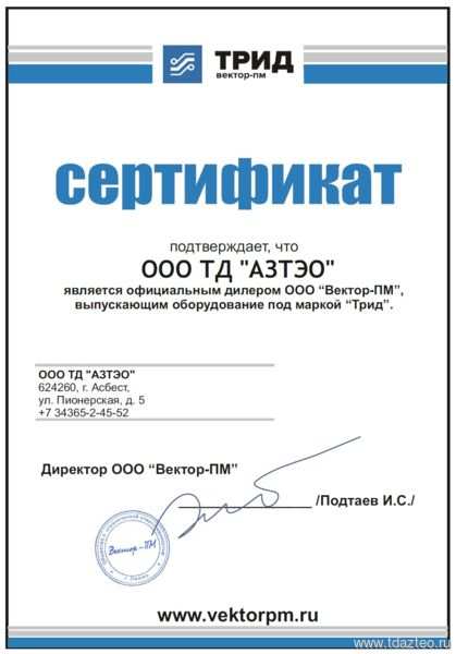
Сертификат Вектор-ПМ
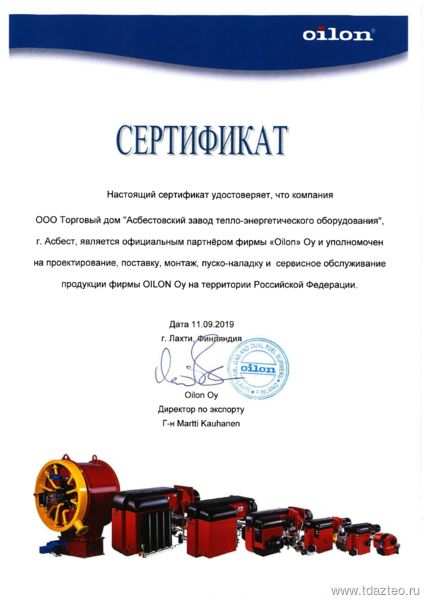
Сертификат OILON
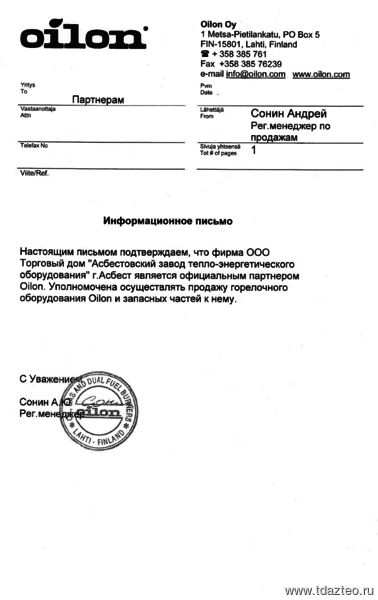
Информационное письмо
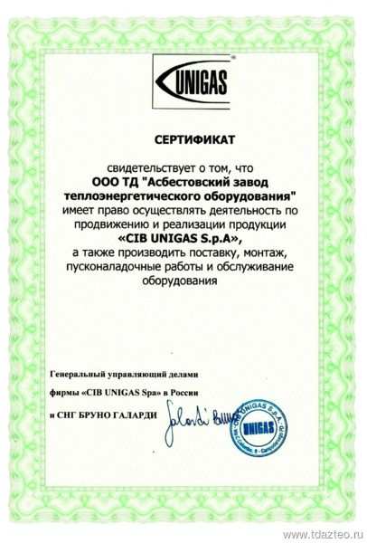
Сертификат CIB UNIGAS S.p.A
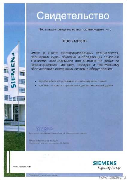
Свидетельство специалистов
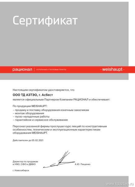
Сертификат РАЦИОНАЛ
Свидетельство BALTUR
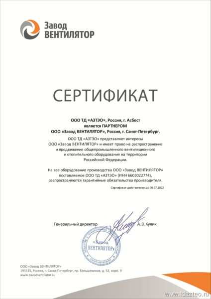
Сертификат «Завод Вентилятор»
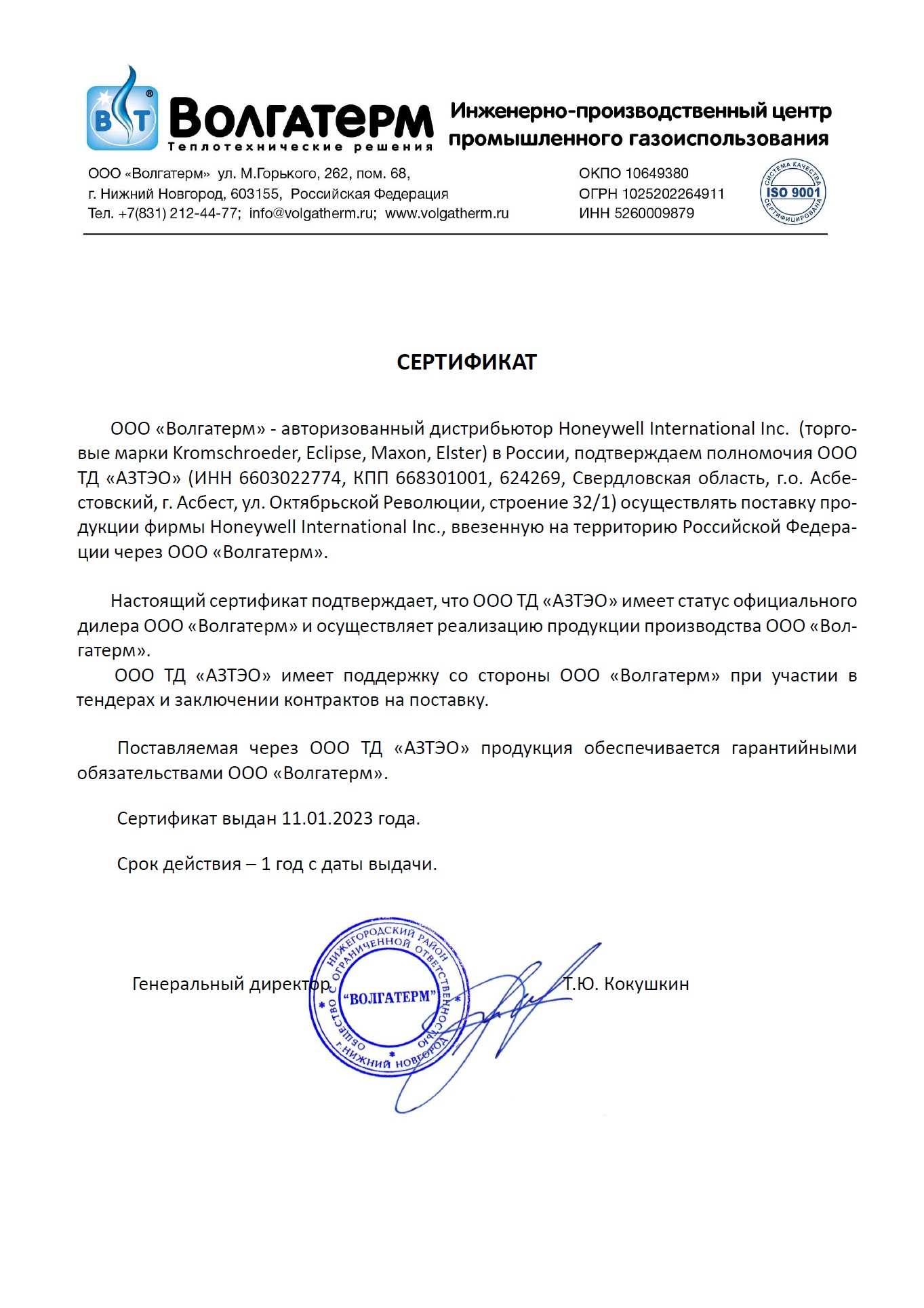
Сертификат ООО «Волгатерм»
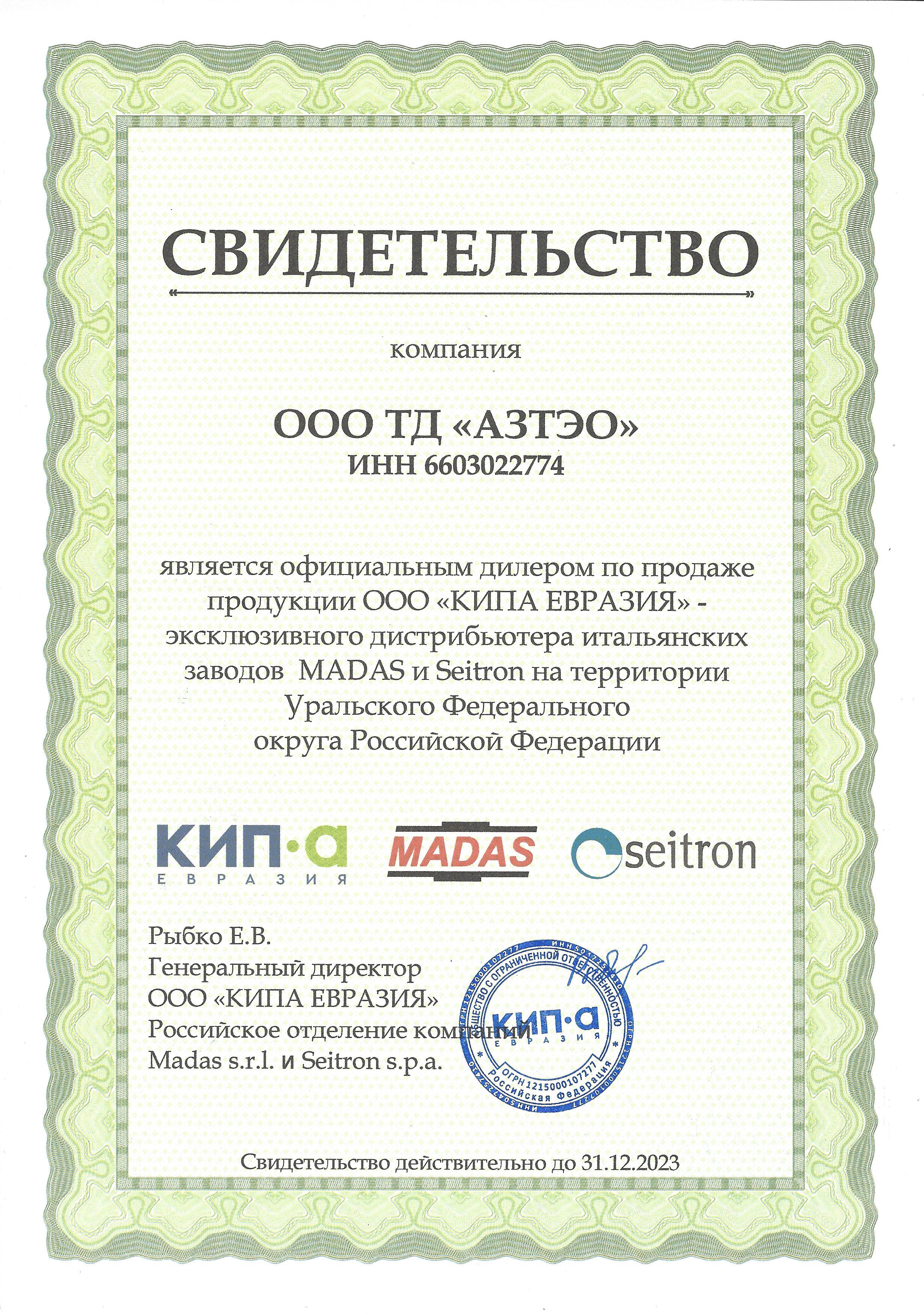
Свидетельство ООО «КИП Еврвзия»
Услуги
Оплата и доставка
Оплата товара производится по выставленному счету от нашей организации.
Самовывоз.
г. Асбест, ул. Октябрьской революции, 32/1,
время работы: 8:00-17:00
Отгрузка курьерскими службами СДЭК, DPD и др.
Отгрузка транспортными компаниями Деловые Линии, КИТ и др.
Доставка до курьерских и транспортных компаний бесплатная.
Производители продукции
Видео о товаре
x
Контакты
Общество с ограниченной ответственностью
Торговый дом «Асбестовский завод тепло-энергетического оборудования»
Адрес:
624260, Российская Федерация, Свердловская область, город Асбест, ул. Октябрьской революции, 32/1
Телефоны для связи:
- +7 (34365) 2-45-52 — коммерческий отдел
- td@azteo.ru
- +7 (34365) 2-87-74 — отдел сбыта
- zakaz@azteo.ru
ОГРН 1096603000636
ИНН 6603022774
Коптелов Андрей Павлович
Директор
Задайте вопрос
Наши специалисты ответят на любой интересующий Вас вопрос
Задать вопрос
Мы на карте:
Specifications:1060/1060344-btg_15.pdf file (20 May 2023) |
Accompanying Data:
baltur BTG 15 Burner PDF User Manual Manual (Updated: Saturday 20th of May 2023 09:13:30 AM)
Rating: 4.2 (rated by 2 users)
Compatible devices: GI Series, TBG 45 PN-V, TBG 2000 ME, btg 15 me, TBG 45 P, SPARK 35LX, TBML 450LX ME, GI 1000 LX.
Recommended Documentation:
Text Version of User Manual Manual
(Ocr-Read Summary of Contents of some pages of the baltur BTG 15 Document (Main Content), UPD: 20 May 2023)
-
80, 78 / 87 0006080876 ed 2007/02 BRÛLEUR GAZ NATUREL UNE ALLURE Signal de visualisation du programme Le microprocesseur contrôle non seulement le déroulement du programme, mais aussi le système d’information. Les différentes phases du programme peuvent être distinguées grâce à un code clignotant. Les …
-
86, baltur BTG 15 84 / 87 0006080876 ed 2007/02 BRÛLEUR GAZ NATUREL UNE ALLURE IRRÉGULARITÉS DE FONCTIONNEMENT 1)Contrôler les fusibles de la ligne d’alimenta- tion. Contrôler les fusibles du boîtier électri- que. Contrôler la ligne des thermostats et du pressostat du gaz. 2)Contrôler l’ouverture des dispositifs…
-
9, 7 / 87 0006080876 ed 2007/02 AVVERTENZE PER L’UTENTE AVVERTENZE PER L’UTENTE PER L’USO IN SICUREZZA DEL BRUCIATORE PER L’USO IN SICUREZZA DEL BRUCIATORE ALIMENTAZIONE ELETTRICA • La sicurezza elettrica dell’apparecchio è raggiunta soltanto quando lo stesso è corretamente colle…
-
70, baltur BTG 15 68 / 87 0006080876 ed 2007/02 BRÛLEUR GAZ NATUREL UNE ALLURE Le brûleur est équipé d’une bride de fi xation coulissante sur la tête de combustion. Lors de l’application du brûleur sur la chaudière, il est nécessaire de positionner correctement cette bride afi n que la tê…
-
36, 34 / 87 0006080876 ed 2007/02 ONE STAGE NATURAL GAS BURNERS The burner is equipped with a moun ting fl ange which slips on the burner head. When applying the burner to the boiler, it is necessary to correctly po sition the fl ange so that the burner head enters the furnace to the e…
-
44, baltur BTG 15 42 / 87 0006080876 ed 2007/02 ONE STAGE NATURAL GAS BURNERS GAS BURNER CONTROL DEVICE GAS LME 21… Legend …. Steady on p Red Off Yellow Yellow Green Green Color code table for multicolor signal lamp (LED) Status Color code Color Waiting time «tw», other…
-
74, 72 / 87 0006080876 ed 2007/02 BRÛLEUR GAZ NATUREL UNE ALLURE X = X = Distance tête/disque X Min. Max. BTG 28 40 68 SCHEMA REGLAGE TETE DE COMBUSTION BTG 28 N° 0002935180 Rev.18/12/2006 Electrode d’allumage Bride de fi xation chaudière Arrivée de gaz 1 Electrode d’ionisation …
-
35, 33 / 87 0006080876 ed 2007/02 BRUCIATORE DI GAS MONOSTADIO IRREGOLARITÀ DI FUNZIONAMENTO 1) Controllare i fusibili della linea di alimentazio- ne. Controllare i fusibili dell’apparecchiatura elettrica. Controllare la linea termostati e del pres sostato del gas. 2) Controllare l’apertu…
-
baltur BTG 15 User Manual
-
baltur BTG 15 User Guide
-
baltur BTG 15 PDF Manual
-
baltur BTG 15 Owner’s Manuals
Recommended: 200 MkII, Lucra, EX350
-
Viessmann Vitoflame 100
VitoflameĂ100 oil burnerfitted to VitoplexĂ100Service instructionsfor heating engineersVitoflameĂ100Oil pressure jet burner (typeĂVEĂIII)for VitoplexĂ100Rated output 90 to 210ĂkWSee notes on applicability, pageĂ2.VITOFLAME 1005692Ă533ĂGBăăă5/2003Please keep safe …
Vitoflame 100 52
-
ILVE T906 LMP
Combining the latest in cook top technology with ILVE’s versatile ovens, you’ll nd yourself running out of things to cook with ILVE’s Titanium cooking range. Italian design and the superior quality synonymous with all ILVE products ensure this is no ordinary kitchen appliance.Choose from 3 different cooking su …
T906 LMP 2
-
LAMBORGHINI ECO 14/2
BRUCIATORICALDAIE MURALI E TERRA A GASGRUPPI TERMICI IN GHISA E IN ACCIAIOGENERATORI DI ARIA CALDATRATTAMENTO ACQUACONDIZIONAMENTO03/2006Cod. 97.00158.0/1LAMBORGHINI CALOR S.p.A.VIA STATALE, 34244040 DOSSO (FERRARA) ITALIATEL. ITALIA 0532/359811 — EXPORT 0532/359913FAX ITALIA 0532/359952 — EXPORT 0532/35 …
ECO 14/2 13
-
Empire Comfort Systems VFSE-18-1
INSTALLATION INSTRUCTIONS AND OWNER’S MANUALUNVENTED GAS LOG HEATERMODELSINTERMITTENT MODELSVFSE-(18,24,30)-1Vent-Free Burner- …
VFSE-18-1 24
Additional Information:
Popular Right Now:
Operating Impressions, Questions and Answers:
Table of Contents for baltur BTG 15:
-
66 / 87 0006080876 ed 2007/02 QUEMADOR DE GAS NATURAL DE UNA ETAPA ESQUEMA DE PRINCIPIO PARA REDUCIR LA PRESIÓN G.L.P. CON DOS SALTOS PARA QUEMADOR O PARA CALDERA PRESOSTATO DEL AIRE Regular el presostato del aire tras haber realizado las demás regulaciones del quemador con el presostato del aire regulado al inicio de la escala. Cuando el quemador funciona con la potencia requerida, girar lentamente el tornillo central en el sentido de las agujas del reloj hasta que se bloquee el quemador. A continuación girar media vuelta el tornillo en el se
-
48 / 87 0006080876 ed 2007/02 ONE STAGE NATURAL GAS BURNERS NOTES ON USE OF PROPANE (L.P.G.) We think it would be useful to inform you on a few points regarding use of liquid propane gas (L.P.G.). 1) Approximate evaluation of running costs a) 1 m 3 of liquid gas in gaseous state has heating power inferior by about 22.000 kcal. b) to obtain 1 m 3 of gas about 2 kg of liquid gas are required. This is equal to about 4 litres o
-
54 / 87 0006080876 ed 2007/02 QUEMADOR DE GAS NATURAL DE UNA ETAPA REGULACIÓN DEL CABEZAL DE COMBUSTIÓN BTG 15 Entrada del gas Arandela de conexión a la caldera X = Distanciacabezal/disco = Distanciacabezal/disco Electrodo de encendido N° 0002934171 Rev.26/05/2004 X = Distanciacabezal/disco REGULACIÓN DEL CABEZAL DE COMBUSTIÓN BTG 20 X X Min. Min. Max. Max. BTG 15P 59 75 N° 0002935000 Rev.25/08/2006 X Min. Max. BTG 20 5 13 N° 0002934171 Rev.22/10/2004 NOTA: Disminuyendo la dist
-
56 / 87 0006080876 ed 2007/02 QUEMADOR DE GAS NATURAL DE UNA ETAPA Verifi car durante la fase de montaje del ventilador que se respete la medida indicada en la fi gura. ESQUEMA DE MONTAJE DEL VENTILADOR USO DEL QUEMADOR El quemador tiene un funcionamiento completamente automático y por ello no hacen falta maniobras de regulación durante su funcionamiento. La posición de “bloqueo” es una posición de seguridad en la que el quemador se pone automáticamente cuando algún componente del quemado
-
10 / 87 0006080876 ed 2007/02 Estas advertencias tienen la fi nalidad de contribuir a la seguridad cuando se utilizan las partes que se usan en instalaciones de calefacción de uso civil y producción de agua caliente para uso sanitario, indicando qué hay que hacer y las medidas que hay que adoptar para evitar que sus características originarias de seguridad dejen de serlo por una eventual instalación incorrecta, un uso erróneo, impropio o inadecuado. La difusión de las advertencias suministradas en esta
-
76 / 87 0006080876 ed 2007/02 Tableau des codes d’erreur Code clignotement rouge de l’indicateur (LED) “AL” à term. 10 Cause possible 2 clignotements Allumé Aucune présence de fl amme à la fi n du “TSA” (temps de sécurité à l’allumage) — Vannes combustible défectueuses ou sales — Détecteur de fl amme défectueux ou sale — Mauvais ré
-
39 / 87 0006080876 ed 2007/02 ONE STAGE NATURAL GAS BURNERS — Observe the measurements indicated in the diagram when fi tting the fan. FAN ASSEMBLY DIAGRAM USE OF THE BURNER The burner operates fully automatically, therefore it is non necessary to carry out any kind at adjustment during its operating. The “block” position is a safety position reached by the burner automatically w
-
19 / 87 0006080876 ed 2007/02 BRUCIATORE DI GAS MONOSTADIO
Quando il bruciatore è acceso occorre verifi care, come esposto precedentemente, l’erogazione di gas e la combustione con gli appositi strumenti. In funzione dei rilievi effettuati si procede variando, se necessario, l’erogazione del gas e della relativa aria di combustione per adeguare l’erogazione al valore desiderato per il caso specifi co (potenza caldaia) ovviamente occorre anche verifi care che i valori della CO 2
-
49 / 87 0006080876 ed 2007/02 ONE STAGE NATURAL GAS BURNERS GENERAL DIAGRAM FOR TWO-STAGE L.P.G. PRESSURE REDUCTION FOR BURNER OR BOILER AIR PRESSURE SWITCH Regulate the air pressure switch after fi rst carrying out all the other burner adjustments with the air pressure switch adjusted to the start of the scale. With the burner operating at the requested power level, slowly turn the central screw clockwise until the burner locks out. Then give the screw a ha
-
46 / 87 0006080876 ed 2007/02 ONE STAGE NATURAL GAS BURNERS COMBINED DUNGS VALVE (monobloc) mod.MB-DLE…B01 1 — Acces to stabilizer regulating screw 2 — Acces knob for manoeuvring ignition output regulator 3 — Regulating knob for maximum delivery 4 — Locking screw for regulating knob 5 — Principle valve (2-stage opening) 6 — Safety valve (rapid) 7 — Pressure tap (to control pre
Questions, Opinions and Exploitation Impressions:
You can ask a question, express your opinion or share our experience of baltur BTG 15 device using right now.





 Quando il bruciatore è acceso occorre verifi care, come esposto precedentemente, l’erogazione di gas e la combustione con gli appositi strumenti. In funzione dei rilievi effettuati si procede variando, se necessario, l’erogazione del gas e della relativa aria di combustione per adeguare l’erogazione al valore desiderato per il caso specifi co (potenza caldaia) ovviamente occorre anche verifi care che i valori della CO 2