
Be2K-Plus OEM’s Manual V200 — August — 014 page 1
1
Be2K-Plus Genset Controller Manual —
Consult Section 17.0 for software upgrades & revisions The information in this document may be subject to change without notice. No part of this document may be copied or reproduced in any form or any means without the prior written consent of Bernini Design Company. Bernini Design assumes no responsibility for any errors which may appear in this instruction manual or in the wiring diagrams. Although Bernini Design has taken all possible steps to ensure that the User Manual is complete, bug free and up-to-date, we accept that errors may occur. If you encounter problems with this instruction manual, please complete this form and send it back to us. FAX Message (++39 0386 31657), From:________________________________________ Name:_____________Company:_____________________Tel/Fax:___________________ I would like to report the following error: _______________________________________ __________________________________________________________________________ Customer Support BERNINI DESIGN SRL ITALY e-mail: [email protected] mobile: ++40 721 241 361. Tel:++39 0386-31445 (fax 31657). Warranty Bernini Design SRL (hereinafter «BD») warrants that Be2K-Plus shall be free from defect in material or workmanship for a period of 3 years from the BD delivery date. BD shall, at its discretion, repair or replace the product without charge. BD shall return the Be2K-Plus to the buyer with the Default parameters at no extra charge. The buyer shall furnish sufficient information on any alleged defects in the product, so as to enable BD to determine their cause and existence. If the Be2K-Plus is not defective, or the product is defective for reason other than covered by this warranty, the buyer will be charged accordingly. This warranty shall not apply if the Be2K-Plus has not been used in accordance with the User Manual and other operating instruction, particularly if any defects are caused by misuse, improper repair attempts, negligence in use or handling. This purchase is non-refundable.
This equipment complies with the EMC protection requirements
!! WARNING !!
High voltage is present inside the Be2K-Plus. To avoid electric-shock hazard, operating personnel must not remove the protective cover. Do not disconnect the grounding connection. The Be2K-Plus can
start the engine at anytime. Do not work on equipment, which is controlled by the Be2K-Plus. When servicing the engine, disconnect the battery and battery charger. We recommend that warning signs be
placed on equipment indicating the above.

Be2K-Plus OEM’s Manual V200 — August — 014 page 2
2
Alphabetic index Air conditioner monitoring ………. 7.03,13.09, 12.11B Alternator Failure ……………………. 12.02B,13.04 Alarms…………………………………….. 13.0, 5.05 Alarm (Horn) TIME-OUT……………. 12.06 Alarm bypass (after start) ………… 12.03A Alarm 1-2 ………………………………… 13.02, 12.10 Auto mode ………………………………. 2.3 Automatic Periodic Test …………… 7.00 Auxiliary Temperature ……………… 12.03C Battery (engine) Alarms …………… 13.03 Battery (telecom) Alarms …………. 7.03 Belt break ………………………………. 13.03 Choke, control …………………………. 12.03A Calibration ………………………………. 5.07 CAN BUS ………………………………… 12.12, 13.01 Characteristics ………………………… 16.0 Charger Alternator/Failure ……….. 14.0/13.03 Clock setting …………………………… 6.00 Clock setting, error ………………….. 6.00 13.01 Clear the memory ……………………. 9.00 Contactors (use) ……………………… 2.21 Connectors, Plugs …………………… 22.0 Connections list ………………………. 22.0 Configurable inputs ………………… 12.10 Configurable outputs ………………. 12.11 Cooling down time …………………… 12.03A Current/Warning/SD……… …………. 12.02A,13.04 Current measurements……… …….. 5.01 Crank timing ……………………………. 12.03A Current Transformer ………………… 12.02B
Defaults…………………………………… 12.13 Dimensions …………………………….. 21.0 Display & Messages ………………… 3.1, 4.0 Droop settings ……………………….. 12.04 Dual set Generator control ……….. 18.20 Earth Failure ……………………………. 12.02B, 13.04 Engine Running ………………………. 14.0 Engine Alarms Bypass …………….. 12.03A Engine Parameters ………………….. 12.03A-B-C-D Energy counter (clear) ……………… 9.00 Emergency (Alarm2) ………………… 12.10 Event history …………………………… 5.06 Events (clear) ………………………….. 9.00 Fail to Start /Stop …………………….. 13.03 Front Panel ……………………………… 1.0 Figure 1 Front Panel Emergency ……………. 13.02A Frequency (Mains/Gen) ……………. 12.01, 12.02 Fuel Level & Alarms ………………… 12.05, 13.06
Generator control …………………… 12.02 A-B Generator Voltage/Hz ………………. 12.02A,13.04 Generator Failure …………………… 12.02B,13.04 Glow Plugs ……………………………… 12.03 Hour Counter ………………………….. 12.06 Horn Programming …………………. 12.06 Idle time …………………………………. 12.04 Idle speed ………………………………. 12.04 Inputs (Programmable) ……………. 12.10 Inputs 1—5 Alarm ……………………. 13.02 kW,kVA (Max,Min) …………………… 5.03, 12.02B,13.04 KM-KG Failure ………………………… 13.04 Language selection ………………… 11.0 Lamp Test, LEDs …………………….. 3.0 Low Battery voltage ………………… 13.03 Locked by remote control ……….. 13.02B Mains Failure/Restore ……………… 12.01 Maximum run time …………………… 13.08, 7.02 Mains Simulated ……………………… 12.10 Measurements ………………………… 5.0 Menu (parameter) …………………… 12.00 Maintenance Timers ………………… 8.0, 13.08 Memory and Memory Error ………. 9.00, 13,01 Memory (clear) ………………………… 9.00 Manual mode ………………………….. 2.20 Modem settings ……………………… 10.02 NFPA-110 ………………………………. 12.06, 18.30

Be2K-Plus OEM’s Manual V200 — August — 014 page 3
3
OEM Password ……………………….. 9.13 Oil pressure ……………………………. 12.03B,13.07 Oil temperature page ………………. 12.03B Outputs (programmable) ………….. 12.11 Operating modes …………………….. 2.0 Over Current ……………………………. 12.02A Over Speed ……………………………… 12.04,13.03 Overload (option [29])………………. 12.10,13.04 Over Frequency/Voltage…………… 12.02A,13.04 Panel emergency …………………….. 13.02 Parameters ……………………………… 4.00, 12.00 Parameter error ……………………….. 13.01 Parameters reading …………………. 9.00 Password(s) ……………………………. 4.00, 9.10, 9.13 Periodic test (automatic) ………….. 7.00 Pick-up (error) …………………………. 12.04, 13.03 Program, Programming ……………. 12.00 Pre Glow …………………………………. 12.03A Power Supply ………………………….. 16.00 Push buttons …………………………… 1.0 Pump fuel (tank) ………………………. 12.05,13.06 Rest time…………………………………. 12.03A Read Parameters …………………….. 4.00, 12.00 Reverse Power ………………………… 12.02B, 13.04 Rental settings ………………………… 7.00, 13.08 Remote Engine test …………………. Table 12.10 [25] Remote Lock …………………………… 13.02B Rental Genset test …………………… Table 12.10 [26] Run Timeout ……………………………. 7.02, 13.08 R.P.M……………………………………….12.04 RS485 …………………………………….. 10.01
Settings (Parameters) ……………… 12.00 Shutdowns (alarms) ………………… 13.00 Speed settings ………………………… 12.04 Speed indications ……………………. 5.04 Sensors …………………………………. 12.07-08-09 Service & Maintenance ……………. 8.00 Serial number …………………………. 10.00 Sequence Error……………………….. 13.04 Single Phase operation ……………. 18.10 Specifications …………………………. 16.00 Software upgrade ……………………. 17.00 Short circuit ……………………………. 13.04 Start ……………………………………….. 2.20 Start Attempts…………………………. 12.03A Starting Failure ……………………….. 13.03 Stop, Stop solenoid …………………. 12.03A Tank Empty …………………………….. 12.05 TCP-IP …………………………………… 10.0 Temperature alarms ………………… 12.03B, 13.05 Telecom application ………………… 7.02 Test, Remote Test …………………… 22.00 Test (periodic) Test Failure ……… 13.01 Test mode ………………………………. 2.40 Terminal description ……………….. 22.00 Tooth count…………………………….. 12.04 Transformer, Current ………………. 12.02B Troubleshooting ……………………… 15.00 Under Voltage / Frequency ………. 12.02A, 13.04 Under Speed ………………………….. 13.03 User password ……………………….. 9.13 Voltage measurements ……………. 5.01, 5.02 Warm-Up time …………………………. 12.03A Wiring diagram ……………………….. 20.00 Warnings (alarms) …………………… 13.00

Be2K-Plus OEM’s Manual V200 — August — 014 page 4
4
Be2K-Plus OEM’s Manual — Contents 1.0 Introduction ……………………………………………… page 5 2.00 Selecting an Operational Mode ……………….. page 6 2.10 OFF mode ……………………………………………… page 7 2.20 MANUAL mode ………………………………………. page 7 2.21 MANUAL control of the contactors ……………. page 7 2.30 AUTO mode …………………………………………… page 8 2.40 TEST mode ……………………………………………. page 8 3.0 LEDs indicators ……………………………………….. page 8 3.01 LED Display description …………………………. page 9 4.0 GRAPHIC DISPLAY…………………………………… page 9 5.0 Measurements & Events …………………………… page 9 5.01 Generating Set ………………………………………. page 10 5.02 Mains …………………………………………………… page 10 5.03 Power & Energy …………………………………….. page 10 5.04 Engine & Fuel ……………………………………….. page 10 5.05 Alarm Messages ……………………………………. page 11 5.06 Event History ………………………………………… page 12 5.07 Calibration …………………………………………….. page 12 5.08 Calibration Table……………………………………. page 13
6.0 Clock Settings ………………………………………….. page 13 7.0 Test & Rental Program ……………………………… page 14 8.0 Maintenance Timers …………………………………. page 15 9.0 Memory & Passwords ………………………………. page 15 10.0 Communications & Serial interfaces ……….. page 16 10.01 Node address ……………………………………… page 16 10.02 Modem & Phonebook …………………………… page 17 10.03 TCP-IP settings……………………………………. page 17 11.0 Display & Languages ……………………………… page 17 12.0 Programming & Automation Parameters … page 18 12.01 Mains Control ………………………………………. page 19 12.02 Generator Parameters …………………………. page 20 12.03 Engine Parameters ……………………………… page 21 12.04 Speed Parameters ………………………………. page 23 12.05 Fuel Settings ………………………………………. page 23 12.06 Miscellaneous …………………………………….. page 24 12.07 Oil sender Table (Ohm-mA-V) ………………. page 24 12.08 Coolant sender Table (Ohm-mA-V) ……….. page 24 12.09 Fuel sender Table (Ohm-mA-V) ……………. page 24 12.10 Configurable Inputs …………………………….. page 25 12.11 Configurable Outputs …………………………… page 26 12.12 Can Bus settings…………………………………. page 27 12.13 Restore Default …………………………………… page 27

Be2K-Plus OEM’s Manual V200 — August — 014 page 5
5
13.0 Alarms, Warnings & Shutdowns ……………… page 28 13.01 Clock & Periodic test alarm ………………….. page 28 13.02 Emergency alarm & Shutdowns ……………. page 28 13.03 Miscellaneous engine alarms ……………….. page 29 13.04 Alternator & Contactors alarms ……………. page 29 13.05 Temperature alarms …………………………….. page 30 13.06 Fuel Level alarms…………………………………. page 30 13.07 Oil Pressure alarms ……………………………… page 31 13.08 Maintenance and Rental alarms ……………. page 31 14.0 Engine Running /charger alternator page .. page 31
15.0 Troubleshooting guide …………………………… page 32 15.01 Testing the inputs ………………………………… page 33 15.02 Testing the pushbuttons ………………………. page 33 15.03 Testing the outputs ……………………………… page 34 15.04 Testing the analogue input …………………… page 34 15.05 Testing the measurements …………………… page 34 16.0 General Specifications …………………………… page 35 17.0 Software Upgrades & Revisions …………….. page 35 18.0 Application Notes ………………………………….. page 36 19.0 Panel builder notes………………………………… page 38 20.0 Typical application wiring ……………………….. page 39 21.0 Rear view and Dimensions …………………….. page 40 22.0 Terminal description ……………………………… page 41, 42
SECTION 1.0 — INTRODUCTION
!! WARNING !!
The Be2K-Plus can start the engine at anytime. Do not work on equipment, which
is controlled by the Be2K-Plus. When servicing the engine, disconnect the battery and battery charger. We recommend that warning signs be placed on
equipment indicating the above.

Be2K-Plus OEM’s Manual V200 — August — 014 page 6
6
The Be2K-Plus integrates a 3-Phase Automatic Mains Failure (A.M.F.) module, an Automatic Transfer Switch controller (A.T.S.) and a Generating Set controller. The Be2K-Plus provides visual indication by means of LEDs and Displays for all parameters and alarms. The Be2K-Plus features programmable settings and complies with NFP110 CAN/CSA-C282-M89 regulations. It provides RS485, RS232 and CAN-BUS (J1939) interfaces. Figure 1 illustrates the layout of the front panel.
Figure 1: Front Panel layout
SECTION 2.0 — SELECTING AN OPERATIONAL MODE The mode of operation is selected by pushbuttons and indicated by means of green LEDs:
NOTE: If the Be2K-Plus was in TEST or AUTO prior to power down, when you switch on the power supply, the Be2K-Plus enters the AUTO mode. In the other cases, the Be2K-Plus will enter the OFF mode. The following sections describe the modes
of operation

Be2K-Plus OEM’s Manual V200 — August — 014 page 7
7
2.10 OFF mode Push the [OFF] pushbutton: you clear the fault alarms and you are allowed to program the parameters (sections 9.00 &12.0 ). The Display and LEDs are turned off; a dot on the display will blink slowly. Push one of the pushbuttons on the front panel to turn on the Be2K-Plus. 2.20 MANUAL mode The MANUAL mode allows you to manually control the Engine and Contactors.
2.21 Manual Control of the Contactors To control the contactors follow the instructions:
! ! WARNING ! !
LINE VOLTAGE IS EXPOSED WITHIN THE Be2K-Plus AND ANCILLARY CIRCUITRY EVEN WHEN THE GREEN LEDs ARE TOTALLY OFF
START Pushbutton
Manual Engine Control
STOP Pushbutton
Engine Running green LED
Instructions
Push the [MAN] pushbutton to select the MANUAL mode. Push the [START] pushbutton until engine starts; the display will automatically open the ‘ENGINE STATUS PAGE’ with information about the start sequence (see section 5.04). When the engine is running, the green LED, on the engine drawing, turns on. To stop the engine, push the [STOP] pushbutton until the [STOPPING] message appears on the display. If the engine has already stopped, it is possible to reset the STOP sequence by pressing the [STOP] pushbutton.
Instructions
Select the MANUAL mode, start the engine (see above) and wait until the green LED ‘Generator Available’ turns on. Push the [ KG ] pushbutton to close the contactor of the Generator. To transfer the Load to the Mains wait for the Green Light ‘Mains available’ and push the [ KM] pushbutton: the KG will open and KM will close after a 2-seconds delay; the programmable changeover timer works only in AUTO mode.
To open a contactor, push the [ O ]
pushbutton at anytime.

Be2K-Plus OEM’s Manual V200 — August — 014 page 8
8
2.30 AUTO mode
!! WARNING !!
The Be2K-Plus can start the engine at anytime. Do not work on equipment, which is controlled by the Be2K-Plus. When servicing the engine, disconnect the battery and battery charger. We recommend that
warning signs be placed on equipment indicating the above. Push the [AUTO] pushbutton until the green LED illuminates. The engine starts when the Be2K-Plus detects a Mains failure (section 12.01). The contactor of the Mains opens after the ‘MAINS BREAKER’ timing. After the ‘WARM UP’ time if the voltage and frequency are within the settings, the contactor of the Generator will close (section 12.02A). If the Mains restores, the KG will open. The KM will close following a programmed ‘KM CHANGEOVER’ timing. The engine will stop after a ‘COOL DOWN’ time. If the engine shuts down, the KM closes independently of the Mains status if the NFPA-110 is on (sections 12.06 & 18.30), otherwise the KM will close only if the parameters of the Mains are within the programmed settings. In AUTO mode, the Be2K-Plus will periodically test the engine if the periodic test is correctly programmed (section 7.01). During the test, the green LED of the AUTO mode will continue to blink. In AUTO mode, the Be2K-Plus can start and stop the engine if a remote control is activated (Table 12.10 options [25] or [26]). You can stop the engine at anytime by selecting the MAN mode. (*)NOTE 2.40 TEST mode Push and hold the [AUTO] pushbutton until the green LED starts to blink. The Be2K-Plus will start the engine and transfer the load to the Generator only in case of Mains failure (if not otherwise programmed by the parameter ‘KG TEST CONTROL’ in section 7.02). To exit the TEST mode, push the [AUTO] pushbutton shortly or select an another mode of operation. (*)NOTE
(*)NOTE: If you push the [STOP] pushbutton when the Be2K-Plus is in AUTO or TEST, the ‘FRONT PANEL EMERGENCY’ alarm will energize (section 13.02A). To clear the alarm, select the OFF mode.
SECTION 3.00 — LEDS INDICATORS The table describes the LEDs functions on the front panel (section 1, figure 1). To test the LEDs, select the OFF mode, push and hold the [←F2] and [F3→] pushbuttons simultaneously. For NFPA 110, program an input with option [14] and connect an external pushbutton (see application note on section 18.30).
LED(s) Note LED(s) Note
Indicators of Voltages and Contactor status (Vac, KM, KG….)
4 Leds (Green color). See section 2.21 for the description.
Manual Mode
MAN
Green LED: it turns on indicating the MANUAL mode
Engine Alarm Indicators
4 Led indicators (red) for: -Oil pressure shutdown -Temperature shutdown -Tank Empty shutdown -Generator shutdown
Auto Mode
Green LED: it turns on indicating the AUTO Mode. It will blink in TEST Mode.
RED YELLOW
Red Led indicator: it turns on in case of a shutdown. Yellow Led indicator: it turns on in case of a warning. The display will indicate all details of the alarm(s).
Engine Running (see Fig.1)
Green LED: it turns on when the engine is running.
Current Mode & Voltage Mode (section1, Fig.1)
2 yellow LEDs indicate the mode of operation of the LED display (Voltage or Current). Push [ACK-F1] to toggle the display Mode.

Be2K-Plus OEM’s Manual V200 — August — 014 page 9
9
Section 3.01 LED DISPLAY description The red LEDs Display consists of 3 groups of 4 digits. The display on the TOP indicates Voltage or Current of Phase L1, the display on the MIDDLE the Phase L2 and the display on the BOTTOM, the Phase L3. Two yellow LEDs indicate the mode of the display (Voltage Mode and Current Mode). Push the [ACK-F1] button to toggle the display mode; the other yellow LED will illuminate. See figure 1 in section 1.00.
SECTION 4.00 GRAPHIC DISPLAY MAIN MENU Push the [OFF] to select the OFF mode and push [F2 ←]; the following Main Menu will appear:
MAIN MENU LIST Section Use [ ↑ ] or [ ↓ ] to select a Menu and [→] to enter the Menu
MEASUREMENTS & EVENTS CLOCK SETTINGS TEST & RENTAL MAINTENANCE TIMERS READ PARAMETERS COMMUNICATIONS DISPLAY & LANGUAGE
5.00 6.00 7.00 8.00
12.00 10.00 11.00
Indicates all measurements and events Allows you to set the Clock Automatic Test, Rental and Telecom dedicated functions Programming of scheduled service You can read all parameters and setting Used to broadcast alarms and information Display settings and language selection
PROGRAM PARAMETERS 12.00 Allows you full access to the memory for programming
CLEAR MEMORY CLEAR EVENTS CLEAR ENERGY COUNTER CLEAR N° OF STARTS
9.00
Allows you to clear a particular area of the memory.
USER PASSWORD OEM PASSWORD
9.10 Allows you to set the OEM and USER password
After 30 seconds without operating the [ ↑ ][ ↓ ][ ←][ →] pushbuttons, the display will shutdown.
SECTION 5.00 — MEASUREMENTS & EVENTS Use [ ↑ ] or [ ↓ ] to select this Menu from the MAIN MENU LIST (section 4.0) and push [→].
Display Indication Section Instructions
GENERATING SET MAINS MONITORING POWER & ENERGY ENGINE & FUEL ALARMS STATUS EVENT HISTORY CALIBRATION
5.01 5.02 5.03 5.04 5.05 5.06
5.07-08
Use [ ↑ ] or [↓ ] to select a sub-menu and [→] to enter the submenu.
Push [←] to return back.
ABOUT BE2K-PLUS It provides miscellaneous information about the controller: — Software Version and Release — Engine Model and ECU Type (in case of J1939 use, see also the Be2k-J1939 User Manual)

Be2K-Plus OEM’s Manual V200 — August — 014 page 10
10
Section 5.01 GENERATING SET This Sub-menu indicates the following measurements:
Use [ ↑ ] or [ ↓ ] to select a page, use [ ← ] to return
L1-L2 (V) [XXXX] L2-L3 (V) [XXXX] L1-L3 (V) [XXXX]
CURRENT 1 [XXXX] CURRENT 2 [XXXX] CURRENT 3 [XXXX]
L1-N (V) [XXXX] L2-N (V) [XXXX] L3-N (V) [XXXX]
FREQUENCY [XX.X] SEQUENCE [CW/CCW] CONTACTOR [ON/OFF] EARTH FAULT [X.XX] SIMULATED (+) [ON/OFF]
(+) see option [11] in the table 12.10. It indicates that the Generator presence is simulated
Section 5.02 MAINS MONITORING This Sub-menu indicates the following measurements:
Use [ ↑ ] or [ ↓ ] to select a page, use [ ← ] to return
R — S (V) [XXXX] S — T (V) [XXXX] T — R (V) [XXXX]
R — N (V) [XXXX] S — N (V) [XXXX] T — N (V) [XXXX]
FREQUENCY [XX.X] SEQUENCE [CW/CCW] CONTACTOR [ON/OFF] SIMULATED (++) [ON/OFF] TELECOM VDC (+++) [XX.X]
(++) see option [12] in the table 12.10. It indicates that the Mains presence is simulated
(+++) it indicates the voltage of the Telecom battery pack (in a range 8-60Vdc)
Section 5.03 POWER & ENERGY This Sub-menu indicates the following measurements:
Use [ ↑ ] or [ ↓ ] to select a page, use [ ← ] to return
KVA 1 [XXXX] KVA 2 [XXXX] KVA 3 [XXXX]
KVAR 1 [XXXX] KVAR 2 [XXXX] KVAR 3 [XXXX]
KW 1 [XXXX] KW 2 [XXXX] KW 3 [XXXX]
PF 1 [X.XX] PF 2 [X.XX] PF 3 [X.XX]
TOTAL KW [XXXX] TOTAL KVA [XXXX] TOTAL KVAr [XXXX]
PF TOTAL [X.XX] ENERGY KWH [XXXXXXXXX]
Section 5.04 ENGINE & FUEL This Sub-menu contains information about the status of the engine.
ENGINE STATUS PAGE push the [ ↓ ] to browse all the other pages related to the engine
ENGINE STATUS
[MESSAGE 1]
[MESSAGE 2]
COUNTING [XXXX]
DATE [XX.XX] TIME [XX:XX]
HOUR RUN
[XXXXXXXX]
This page can indicate two messages that describe the status of the engine and the status of the active timer (COUNTING). Possible messages are:
RUNNING NOT RUNNING RUNNING ON LOAD
REST PRELUBE STARTING CRANKING
STOPPING COOLING WARM UP
IDLE SPEED PREGLOW PERIODIC TEST
MAINS BREAKER DELAY MAINS FAILURE DELAY REMOTE TEST
MAINS RESTORE DELAY TELECOM INHIBIT
The engine run hours and Date / Time are also indicated

Be2K-Plus OEM’s Manual V200 — August — 014 page 11
11
Use [ ↑ ] or [ ↓ ] to select a page, use [ ← ] to return
SPEED [XXXX] OIL PRESSURE [XX.X] COOLANT °C [XXX]
FUEL LEVEL [XX] TRANSFER PUMP [ON-OFF] V BATTERY [XX.X] ALTERNATOR V [XX.X] N° / STARTS [XXXXXXXX]
RENTAL H (! ) [XXXX] MAINTEN. 1 (!) [XXXX] MAINTEN. 2 (!) [XXXX] MAINTEN. 3 (!) [XXXX]
( ! ) It indicates the remaining hours before expiring the Maintenance timers and Rental contract (see sections 7.01 & 8.0). If the engine is connected by means of SAE-J1939 (Can Bus), additional pages are available:
Use [ ↑ ] or [ ↓ ] to select a page, use [ ← ] to return
OIL °C [XXX] AUXILIARY °C [XXX]
OIL °C [XXX] SPN 175 OIL LEVEL [XX.X] SPN 98 OIL PRESSURE [XX.X] SPN 100
WATER IN FUEL [ON/OFF] SPN 97 FUEL °C [XXX] SPN 174 FUEL BAR [XXX] SPN 94
FUEL RATE [XXX] SPN 183 PEDAL % [XXXX] SPN 91 TURBO BAR [XX.X] SPN 102
Use [ ↑ ] or [ ↓ ] to select a page, use [ ← ] to return
EXHAUST [XXXX] SPN 173 BAROMETRIC P. [XXXX] SPN 108
COOLANT °C [XXX] SPN 110 COOLANT % [XX.X] SPN 111 COOLANT BAR[XXXX] SPN 109
CRANKCASE BAR [XXXX] SPN 101 BOOST °C [XXXX] SPN 105 INTAKE BAR [XXXX] SPN 106
DEMANDE TORQUE [XXXX] SPN 512 ACTUAL TORQUE [XXXX] SPN 513 LOAD [XXXX] SPN 92
NOTE: Additional information from J1939 will be displayed using the coding of the engine manufacturer (see the engine’s OEM manual). Section 5.05 ALARM STATUS This Sub-menu can contain 10 pages of active alarms together with real time clock indication and alarm information. A typical alarm page is indicated below (see section 13.0 for the list of all alarms):
Instructions
ALARMS PAGE 1 OF 10 OIL PRESSURE WARNING VALUE: 0,8 BAR DD:MM:YY HH:MM:SS
Use [ ↑ ] or [ ↓ ] to browse the content of the pages This page opens automatically in case of alarm(s). The alarm status is
also recorded in the Memory Events register. To return to the MEASUREMENTS pages, push the [ ← ] pushbutton.

Be2K-Plus OEM’s Manual V200 — August — 014 page 12
12
In case of alarms detected via CAN-BUS (J1939), the Be2K-Plus will decode the CAN BUS information. Consult the user manual of the engine manufacturer for further details.
ALARMS PAGE 1 OF 10 [DESCRIPTION OF ALARM] SPNXXX FMI XX DD:MM:YY HH:MM:SS
This page opens automatically in case of alarm(s). The alarm status is also recorded in the Memory Events register (see 5.06). To return to the MEASUREMENTS pages, push the [ ← ] pushbutton.
Section 5.06 EVENT HISTORY This submenu displays 70 pages providing Date & Time information for about 200 Events of: Warnings, Shutdowns, switching of the Contactors and changing of Operating Modes.
Instructions
EVENT HISTORY 1 / 70 EMERGENCY DD:MM:YY HH:MM:SS
Push [ ↑ ] or [ ↓ ] to browse the list of the events. To return to MEASUREMENTS, push the [ ← ] pushbutton. (see section 13.0 for the description of the alarms)
Note: in order to cancel the EVENT HISTORY, use the CLEAR EVENTS menu described in section 9.0. Section 5.07 Calibration Use [ ↑ ] or [ ↓ ] to select this Menu from the MEASUREMENTS & EVENTS Menu. Push [MAN] to select the Manual mode and push [→] to enter the menu. If the function is Password protected, type the password (see section 9.10). If password is valid, the list indicated in TABLE 5.08 will appear.
To calibrate, follow the instructions: ( A ) — Start the engine (if necessary) and wait for the generator to stabilize. ( B ) — Select a parameter by using the [ ↑ ] or [ ↓ ] button. ( C ) — Push the [→] button to enter the numerical field of the parameter. ( D ) — Be sure that the reference measurement is stable and within the recommended range (Table 5.08). ( E ) — Modify the indication of the display, using [ ↑ ] or [ ↓ ], until the display matches the reference. ( F ) — Exit the numerical field using the [←] pushbutton. ( G ) — Select an other function to calibrate or exit using the [←] pushbuttons; you have 3 options:
Push F1 to Save and Exit / < Push F2 to Exit / > Push F3 to Return back ( H ) — Stop the engine, remove the Vdc supply for a minute; connect the Vdc supply. ( I ) — Start the engine and verify the measurement that you calibrated. If necessary repeat the entire procedure. Note: in case of doubt, it is possible to restore the factory calibration by using the [RESTORE] function. After that the Be2K-Plus will ask to choose one of the options : Save, Exit or Return back.

Be2K-Plus OEM’s Manual V200 — August — 014 page 13
13
Table 5.08 Calibration table
Display indication Description & numerical
Field
Unit
Range
Display indication Description & numerical Field
Unit
Range
VOLTAGE L1-N XXX
Volt
200 -250
AUX. TEMP °C XXX Degree Celsius
90 -100
VOLTAGE L2-N XXX OIL TEMPERATURE XXX
VOLTAGE L3-N XXX COOLANT °C XXX
VOLTAGE R-N XXX OIL PRESSURE XX.X Bar 2 — 6
VOLTAGE S-N XXX FUEL LEVEL XX % 70 — 80
VOLTAGE T-N XXX BATTERY XX.X Volt 12 -26
CURRENT L1 XXX Ampere
3 – 5
FREQUENCY XX.X Hertz 48 — 65
CURRENT L2 XXX SPEED XXXX RPM 1300 up to 1500
CURRENT L3 XXX
RESTORE This function allows you to restore the factory calibration. Push [→] to enter the function and follow the instruction that will appear on the display.
SECTION 6.00 — CLOCK SETTINGS
Use [ ↑ ] or [ ↓ ] to select this Menu from the MAIN MENU list (section 4.0) and push [→] to enter the menu. Setting of Clock is allowed in OFF mode only.
Display Indication Instructions
CLOCK DAY 1 CLOCK MONTH 1 CLOCK YEAR 2000 CLOCK HOUR 0 CLOCK MINUTE 0
Use [ ↑ ] or [ ↓ ] to select a function. Push [→] to enter the numerical field. Push [ ↑ ] or [ ↓ ] to set a value. Push [←] to return to the function. After setting the clock, push [ ↓ ] to select the [PUSH F3 TO SET CLOCK] function (see below) in order to start the clock.
DATE FORMAT DD:MM:YY
Select the function, push [→] and [ ↑ ] or [ ↓ ] to select the option MM:DD:YY (Month:Day: Year) instead of DD:MM:YY (Day:Month:Year).
PUSH F3 TO SET CLOCK Push [F3 →] to start up the Be2k-Plus at the proper moment (use an external clock reference)
SECTION 7.00 — TEST & RENTAL PROGRAM ( ‘USER password’ is required for programming ) 7.01: Periodic Test Settings Use [ ↑ ] or [ ↓ ] to select this Menu from the MAIN MENU list (section 4.0) and push [→] to enter the menu.
Display Indication Description
TEST DAY TEST MONTH TEST YEAR TEST HOUR TEST MINUTE
1 1
2008 0 1
Periodic Test setting. You can set the date of the Periodic Test. The engine will run for the [TEST DURATION] time. The Be2k-Plus will repeat the test every [TEST REPEAT] days. After a test, the DATE is automatically updated to inform you about the date of the next TEST attempt. In order to program correctly, make sure not to set the scheduled date at a time that has already occured. Instructions: Use [ ↑ ] or [ ↓ ] to select a function. Push [→] to enter the numerical field. Push [ ↑ ] or [ ↓ ] to set a value. Push [←] to return to the function. After setting date and time, push [ ↓ ] to select the TEST DURATION. Automatic Test works in AUTO mode. The green LED blinks during the Test, and
output with option [55] turns on)
TEST DURATION OFF Duration of the test (1-60 minutes, or OFF to disable the TEST).
TEST REPEAT OFF Repetition rate of the test (1-60 days, or OFF to disable the TEST). Push [←] to return to the function. The Be2k-Plus will start to count-up the time.

Be2K-Plus OEM’s Manual V200 — August — 014 page 14
14
7.02: Rental, EJP (France), Test Mode & Dual Set mode
Display Indication Description
RENTAL CONTRACT OFF You can set up to 9999 hours of rent contract. When the remaining hours drop to less than 48, the ‘RENTAL WARNING’ alarm sets off. At ‘ZERO’ hours, the engine will shutdown. You are required to re-program the timer.
EJP 5” (Effacement des Jours de Pointe).
(Range 1sec — 99 minutes). This timer delays the switching of the contactor of the Generator (KG) if the engine has been started using the EJP (see table 12.10, option [13]).
KG TEST CONTROL OFF Options: [ON or OFF]. The option ON will transfer the Load to the Generator if you select the TEST mode from the front panel. The option OFF will allow you to run the engine without switching the Load. Mains Failure overrides the option [OFF].
RUN TIMEOUT OFF Maximum time allowed for running the engine (up to 24 hours). The option OFF disables the time-out and the engine will run until a stop is required. The counter works in Manual mode also, but it will not shut down the engine. Before selecting AUTO mode, push the OFF button.
2XGEN. + MAINS OFF 1minute up to 24h. See application note described in section 18.20
7.03: Battery monitoring, Telecom Battery monitoring, Room temperature monitoring
Display Indication Description
LOW BATT. START OFF (8-30V).The engine will start when the Battery Voltage (of the engine) falls under the LOW setting. The engine will stop when the voltage rises above the HIGH setting. A delay of 2 minutes prevents a false trigger of the function. Battery voltage is detected on supply input JI1-2-3.
HIGH BATT. STOP OFF
H AUX °C START OFF (Range 0-60°C).The engine will start when the Auxiliary temperature rises above the HIGH setting. The engine will stop when the Auxiliary temperature falls below the LOW setting. A delay of 2 minutes prevents false trigger of the function (see 12.03C for setting the input).
L AUX °C STOP OFF
TELECOM BATT. OFF
Telecom Battery & Room monitoring. You can set the HIGH limit of the Room temperature (use Auxiliary temperature input, see 12.03C) and the LOW limit of the Telecom Battery Pack (8-60Vdc, input JM6) in order to inhibit the start of the Generator in case of Mains failure. Program an output with the option Telecom Room Monitoring ([71]) connected to an input programmed with Mains Simulated option ([12]). In case of Mains Failure, the engine will not start if the temperature is low and the Battery Voltage is above the setting. You can disable one function (BATTERY or TEMPERATURE) by choosing the option OFF.
TELECOM °C OFF
TELECOM V LOW OFF
These parameters allow you to set a warning if the Battery voltage of the TELECOM equipment is low or high. A bypass delay of 2 minutes cancels a false trigger of the warning. The analog input dedicated to this function is the terminal JM6 (8-60Vdc).
TELECOM V HIGH OFF
TELECOM °C LOW OFF
These parameters allow you to set a warning if ambient temperature is low or high . A bypass delay of 2 minutes is added. You can program the analog input in the AUX TEMPERATURE PAGE (section 12.03C) and an output with the option [79] (Table 12.11).
TELECOM °C HIGH OFF

Be2K-Plus OEM’s Manual V200 — August — 014 page 15
15
SECTION 8.0 — MAINTENANCE TIMERS Use [ ↑ ] or [ ↓ ] to select this Menu from the MAIN MENU list (section 4.00) and push [→] to enter the menu. These functions are ‘User password’ protected.
Display Indication Section Instructions
MAINTENANCE 1 OFF MAINTENANCE 2 OFF MAINTENANCE 3 OFF
Use [ ↑ ] or [ ↓ ] to select a function. Push [→] to select the numerical field. Push [ ↑ ] or [ ↓ ] to set a value. Push [←] to return to the function. The timers 1, 2 and 3 set the hours of Maintenance time out. Maintenance 1 and 2 will generate a warning alarm. Maintenance 3 will shutdown the engine. The remaining time is indicated in the ENGINE page (see 5.04). When a timer expires, enter this screen and exit (push [←]). The timer will restart automatically. Restarting of timer(s) is not allowed by remote (e.g. by computer or Modbus).
SECTION 9.00 — MEMORY & PASSWORD Enter the OFF mode, select the function you require from the Main Menu list (see section 4.0). Push [→] to enter the function.
Display Indication Instructions
CLEAR MEMORY (Total cancellation of the memory and restoration of factory settings) CLEAR EVENTS (It cancels the Event History, see section 5.06) CLEAR ENERGY COUNTER (It cancels the counter of the Energy, see 5.03) CLEAR N° OF STARTS (It cancels the number of starts, see 5.04)
To enter the functions listed on the left, you have to provide a correct password as indicated in section 9.10.
Note: some functions indicated on the left, will require a confirmation as indicated below
Push the [ ↓ ] button to select ‘PUSH F3 TO CONFIRM’ and [F3 →] to trigger the operation (figure 9.1). The message [DONE] will appear (figure 9.2).
Figure 9.1 Figure 9.2
PUSH F3 TO EXIT
PUSH F3 TO CONFIRM
DONE
9.10: Password programming 9.11 User or OEM password selection: Enter the OFF mode, select the function you require from the Main Menu list (see section 4.0). Push [→] to enter the function.
Display Indication Instructions
USER PASSWORD OEM PASSWORD
Use [ ↑ ] or [ ↓ ] to select a function and push [→] to enter the function; the following screen will appear (section 9.12 describes an example)

Be2K-Plus OEM’s Manual V200 — August — 014 page 16
16
9.12 User or Oem passwords programming (example for ‘User’):
Display Indication Instructions
ENTER USER PASSWORD CANCEL — — — — OK SELECT OK TO CONFIRM
A) — Use [←] or [→] to select a digit of the password. B) — Push [ ↑ ] or [ ↓ ] to edit the digit (Number or Upper case letter). C) — Repeat steps A) and B) in order to edit the 4-digit password. D) — Select OK using the [→] button (the OK highlights when selected). E) — Push the [→] button to confirm the password.
9.13 User or Oem passwords options:
Display Indication Instructions
CHANGE USER PASSWORD CLEAR USER PASSWORD CHANGE OEM PASSWORD CLEAR OEM PASSWORD
Once you’ve entered the correct password, the Be2k-Plus presents the options to change or to clear the User / OEM password.
A) — Push [ ↑ ] or [ ↓ ] to select the function B) — Push [→] to enter the function C) — Follow menu-driven instructions to complete the task
SECTION 10.0 — COMMUNUCATIONS & SERIAL INTERFACES Use [ ↑ ] or [ ↓ ] to select this Menu from the MAIN MENU list (section 4.0) and push [→] to enter the menu. Additional information is described in the BE-2KPLUS communication User Manual. NOTE: By means of software, provided by us, you are allowed to write into Be2K-Plus the Serial Number and Name of the Location or Plant.
Display Indication Section Instructions
RS485 NODE 1 10.01 Use [ ↑ ] or [ ↓ ] to select a function. Push [→] to select the numerical field. Push [ ↑ ] or [ ↓ ] to set a value. Push [←] to return back.
MODEM SETTINGS 10.02
TCP/IP SETTTINGS 10.03
Section 10.01: RS485 node Push [→] to select the numerical field. Push [ ↑ ] or [ ↓ ] to set a value. Push [←] to return back. The range of the Node address is in between 1 to 127. In order to establish a communication with Be2k-Plus, the Node Address must match the calling device node address.

Be2K-Plus OEM’s Manual V200 — August — 014 page 17
17
Section 10.02: Modem settings The details of these functions are described in the BE-2KPLUS communication User Manual Section 10.03: TCP-IP settings The details of these functions are described in the BE-2KPLUS communication User Manual
SECTION 11.0 — DISPLAY & LANGUAGE
Use [ ↑ ] or [ ↓ ] to select this Menu from the MAIN MENU list (section 4.00) and push [→] to enter the menu.
Display Instructions
LANGUAGE A) — Use [F3 →] button to enter the selection of the language. Choose the language using [ ↑ ] or [ ↓ ]. B) — Push the [ F2 ← ] twice; the display will indicate the 3 options: — EXIT by pushing [ F2 ← ] — SAVE (the selection of the language) by pushing [F1] — RETURN BACK (to selection language) by pushing [F3 →] Languages available are ENGLISH-ITALIAN-FRENCH-GREEK-SPANISH-RUSSIAN
CONTRAST 75% You can optimize the text-readability of the display: — Push [F3 →] button to enter; push [ ↑ ] or [ ↓ ] to choose 25%, 50% ,75% or 100% — Push [←] to return BACK
SECTION 12.00 — PROGRAMMING PARAMETERS
We recommend that you use the software Be2K-Plus SCADA for programming the controller (see the Be2K-Plus SCADA software guide). Be2K-Plus however, allows programming using the push buttons on the front panel. Follow the instructions: ( 1 ) – Preliminary operation: Push OFF pushbutton to enter the OFF mode. Select the PROGRAM PARAMETERS Menu from the Main Menu list (section 4.00) ( 2 ) – Password: If a password was inserted, the Be2k-Plus will present a screen to enter the password (see below)
Display Indication Note
ENTER USER PASSWORD CANCEL — — — — OK SELECT OK TO CONFIRM
A) — Use [←] or [→] to select a digit of the password. B) — Push [ ↑ ] or [ ↓ ] to edit the digit (Number or Upper case letter). C) — Repeat steps A) and B) in order to edit the 4-digit password. D) — Select OK using the [→] button (the OK highlights when selected). E) — Push the [→] button to confirm the password. If the password is correct, the message [PASSWORD OK] will be displayed

Be2K-Plus OEM’s Manual V200 — August — 014 page 18
18
( 3 ) – Parameters Menu: If entered a proper password, the Be2k-Plus presents the menu of the programmable parameters:
PARAMETER MENU
See Section:
PARAMETER MENU
See Section:
MAINS PARAMETERS GENERATOR PARAMETERS ENGINE PARAMETERS SPEED PARAMETERS FUEL SETTINGS MISCELLANEOUS AUXILIARY °C INPUT OIL °C INPUT
12.01 12.02 A-B 12.03 A-B-C 12.04 12.05 12.06 12.08 (Table) 12.08 (Table)
OIL PRESSURE INPUT COOLANT °C INPUT FUEL LEVEL INPUT CONFIGURABLE INPUTS CONFIGURABLE OUTPUTS CAN BUS SETTINGS RESTORE DEFAULTS
12.07 (Table) 12.08 (Table) 12.09 (Table) 12.10 12.11 12.12 12.13
( 4 ) – Select the programmable parameters: Choose the MENU that requires programming by using the [ ↑ ] or [ ↓ ] buttons and push [→]. The list of the parameters will appear on the display ( 5 ) – Programming:
5 A — Select a parameter by using the [ ↑ ] or [ ↓ ] buttons (see sections 12.01——12.13) 5 B — Push the [→] button to enter the numerical field of the parameter
5 C — Modify the parameter using [ ↑ ] or [ ↓ ] 5 D — Exit the numerical field using the [←] pushbutton. 5 E — You can modify an other parameter by repeating the steps 5A-B-C-D 5 F — Use the [←] pushbutton to return. The Be2K-Plus will provide you 3 options:
Push F1 to Save / < Push F2 to Exit / > Push F3 to Return back
5 G — Choose the proper option; disconnect the supply, re-apply the supply and verify that the modifications have been saved in a way that Be2K-Plus operates according to your need.
Reading Parameters Instructions To read the parameters without entering the programming, follow the instructions: ( 1 ) – Push the [OFF] button to enter the OFF mode; push [←F2] ( 2 ) – Select from the MAIN MENU LIST (see section 4.0), the function [READ PARAMETERS]; push [F3→] The PARAMETERS MENU will appear on the screen of the display (see below). ( 3 ) – Choose one Menu from the PARAMETERS MENU list by using the [ ↑ ] or [ ↓ ] buttons and push [F3→] to enter the Menu. Push [F4 ↑ ] or [F5 ↓ ] to browse the parameters. Push [←F2] to return.

Be2K-Plus OEM’s Manual V200 — August — 014 page 19
19
Section 12.01 MAINS PARAMETERS submenu note: (“) stands for seconds, (‘) stands for minutes
Display Indication Min Max Options Note
MAINS BREAKER 5”
0
59’
—
In case of Mains failure, the [MAINS BREAKER] timer will delay the opening of the contactor.
MAINS FAILURE 5” MAINS RESTORE 5”
0 0
23h,59” 23h,59”
— —
These two timers will delay the start and stop of the engine in order to cancel false Mains Failure/Restore conditions.
KM CHANGEOVER 2.0 0.1” 15.0” — Dead time between the switching of the contactors.
UNDER VOLTAGE 320 OVER VOLTAGE 500
60 60
9990 9990
OFF OFF
Define operating limits for the Mains. If a parameter is out of limits, a Mains failure condition will occur.
UNDER HZ 47.0 OVER HZ 53.0
20.0 20.0
70.0 70.0
OFF OFF
PHASE MODE 3 PH 1PHASE, 3PH, 3PH+CW or 3 CCW
1 = Single phase, 3 = 3 Phases without sequence control. The option CW/CCW controls the requested sequence of Phases. In case of reverse sequence, a Mains failure condition will occur. (Section 18.10 for single Ph mode)
PHASE UNBALANCE
OFF
10 999 OFF If the difference between phases rises above the setting, a Mains failure condition will take place. The option [OFF] disables the monitoring.
VAC RATIO 1.0 1.0 15.0 — It allows the use of voltage transformer extending the reading up to 9990Vac.
Section 12.02A GENERATOR CONTROL submenu note: (“) stands for seconds, (‘) stands for minutes
Display Indication Min Max Options Note
UNDER VOLTAGE 320 BYPASS DELAY 6”
60 1”
9990 15”
OFF —
Define operating limits for the Generator. If a parameter is out of the limits, the Be2k-Plus triggers the alarm and stops the engine. Under V & Under Hz works only if the contactor of the Generator is closed. The option ON in the [ALTERNATOR FAIL] parameter, will shutdown the engine if the parameters of the Generator are outside of the operating range for at least 300 seconds from engine start.
OVER VOLTAGE 500 BYPASS DELAY 6”
60 1”
9990 15”
OFF —
UNDER HZ 47.0 BYPASS DELAY 6”
20.0 1”
70.0 15”
OFF —
OVER HZ 53.0 BYPASS DELAY 6”
20.0 1”
70.0 15”
OFF —
WARNING CURRENT OFF BYPASS DELAY 6”
1 1”
9990 15’
OFF —
OVER CURRENT OFF BYPASS DELAY 6”
1 1”
9990 15’
OFF —
SHORT CIRCUIT OFF BYPASS DELAY 0,5”
1 0.0”
9990 15.0”
OFF —
ALTERNATOR FAIL OFF
ON or OFF
PHASE MODE 3 PH (Section 18.10 for single Ph
mode)
1PHASE, 3PH, 3PH+CW or 3 CCW
1= single Phase, 3=3 Phases without sequence control. The option CW/CCW controls the requested sequence of Phases. In case of reverse sequence, the engine will shutdown (‘PHASE SEQUENCE ERROR’, section 13.04).

Be2K-Plus OEM’s Manual V200 — August — 014 page 20
20
Section 12.02B GENERATOR CONTROL submenu note: (“) stands for seconds, (‘) stands for minutes
Display Indication Min Max Options Note
MAX KW LIMIT OFF BYPASS DELAY 30”
10 1”
9990 59’
OFF —
To monitor the KW, you can program two outputs with option [10] and [11] (see Table 12.10). The outputs energize if KW is outside limits and reset if KW is within limits. A bypass delay should be programmed according to the characteristics of the LOAD.
MIN KW LIMIT OFF BYPASS DELAY 30”
10 1”
9990 59’
OFF —
KVA SHUT DOWN OFF BYPASS DELAY 30”
10 1”
9990 59’
OFF
—
If the power rises above the [KVA SHUT DOWN] limit for at least the [BYPASS DELAY] time, the Be2K-Plus opens the contactor and shuts down the engine, The [OFF] setting (>9990KVA) disables the alarm.
REVERSE POWER OFF BYPASS DELAY 1”
10 1”
9990 15”
OFF —
If kW1 (or 2, 3) becomes negative and exceeds the limit, the KG opens and the engine will shutdown after a cooling down time.
EARTH FAULT OFF BYPASS DELAY 1.0”
0.1 0.3”
99.9 10”
OFF —
Provides Earth Fault current (or Differential Protection) Monitoring.
CT SIZE EARTH 5 VAC RATIO 1.0
5
1.0
9990
15.0
— —
It defines the size of the CT for the Earth Current
It extends the reading range of the Vac up to 9990Vac
PHASE UNBALANCE OFF BYPASS DELAY 15”
10 1
999
59”
OFF If the difference of voltage between phases rises above the setting, the KG opens and the engine will shutdown after a cooling down time. The option [OFF] disables the Unbalance monitoring.
CT SIZE L1 L2 L3 500 5
9990
— It defines the sizes of the CT for the phases L1-2-3 of the Generator.
Section 12.03 A ENGINE PARAMETERS submenu note: (“) stands for seconds, (‘) stands for minutes
Display Indication Min Max Options Note
PRE-LUBE TIME 2”
1”
15”
It energizes the Pre-lube pump (option [63], section 12.11) or it delays the crank if necessary (option [46]).
CRANK TIME 5” CRANK REST TIME 5” START ATTEMPTS 3
1” 3”
3
15” 15” 15
These parameters define the start sequence of the engine.
PREGLOW TIME OFF PREGLOW MODE 1
1” —
15’ —
OFF 1-2-3-4
See Figure 12.03A in order to choose the proper working logic of Output JC1.
CRANK TERMINATION CHARGER VOLTAGE 8.0 GENERATOR VAC 60 GENERATOR HZ 25.0 SPEED RPM 300 CANBUS OFF
CRANK TERMINATION programming These parameters allow you to terminate the crank when the engine starts to run.
3.0 30.0 OFF Charger alternator voltage (input #JC10)
60 9990 OFF Generator Voltage Line to Neutral (inputs #JA5-6-7-8)
20.0 70.0 OFF Generator Frequency (inputs #JA5-6-7-8)
100 800 OFF Pick-up or ‘W’ (you are required to program the TOOTH COUNT as indicated in section 12.04.
1 60 OFF CAN BUS. You can set the number of times that Be2k-Plus detects a true engine running condition.
GAS PURGE 1”
1”
15”
OFF
It allows you to use a GAS fuelled engine; (Program an output with option [47], see table 12.11).
WARM UP 15”
0
59’
—
The Generator Contactor will close after [WARM UP].

Be2K-Plus OEM’s Manual V200 — August — 014 page 21
21
COOL DOWN TIMER 15”
0
59’
—
The will run engine run Off-Load.
STOP SOLENOID 15”
1”
15’
—
Energized to stop solenoid timing (Output #JC4)
BELT BREAK VDC 8.0
3.0
30.0
OFF
Setting to detect Charger Alternator Failure
ALARM BYPASS 10”
2”
99”
—
Bypass timing for Oil, Temperature and Alarm 1 alarms.
FAIL TO STOP OFF ON or OFF You can disable the FAIL to Stop alarm.
Figure 12.03A: Preglow-modes timing diagram
Starting Motor Total rest timing
Pre-glow mode 1
Pre-glow mode 2
Pre-glow mode 3
(Crank pilot) Out-JC6
Out-JC1
Out-JC1
Out-JC1
Out-JC1Pre-glow mode 4 (Choke)
Total rest timing
Crank termination (the engine starts to run) Section 12.03B ENGINE PARAMETERS submenu note: (“) stands for seconds, (‘) stands for minutes
Display Indication Min Max Options Note
OIL PRESSURE PAGE LOW BAR WARNING OFF LOW BAR SHUT. OFF ANALOG INPUT OFF ANALOG MODE (*) [OHM]
0.1 0.1
20.0 20.0
OFF OFF
It allows you to monitor the Oil Pressure (BAR). You can set a Low Oil Pressure warning or a Low Oil Pressure shutdown. The alarm is ignored during By-pass timing.
[1] to [5] select the analog input. The setting [OFF] disables the input; the display will indicate dashes instead of a BAR.
[OHM] for sensor input [3] to [5]. [4-20MA]/[0-10V]/[0-5V] for inputs [1] & [2]. The [J1939] detects Oil Pressure form CAN-BUS.
OIL TEMPERATURE PAGE HIGH °C WARNING OFF HIGH °C SHUTDOWN OFF ANALOG INPUT OFF ANALOG MODE (*) [OHM]
1 1
250 250
OFF OFF
It allows you to monitor the Oil Temperature. The alarm is ignored during By-pass timing.
[1] to [5] select the analog input JM1 — — 5. The setting [OFF] disables the input; the display will indicate dashes instead of °C degree.
[OHM] for sender input [3] to [5]. [4-20MA]/[0-10V]/[0-5V] for inputs [1] & [2]. The [J1939] detects Oil Temperature form CAN-BUS.
(*) The functions mA/Bar, V/Bar, mA/°C or V/°C are indicated in tables 12.07-08-09 .

Be2K-Plus OEM’s Manual V200 — August — 014 page 22
22
Section 12.03C ENGINE PARAMETERS submenu note: (“) stands for seconds, (‘) stands for minutes
Display Indication Min Max Options Note
COOLANT PAGE HIGH °C WARNING OFF LOW °C WARNING OFF HIGH SHUTDOWN OFF ANALOG INPUT OFF ANALOG MODE (*) [OHM]
1 1 1
250 250
250
OFF OFF OFF
It allows you to monitor the Coolant Temperature. You can set a Low / High limit. The alarms are ignored during By-pass timing.
[1] to [5] select the analog input JM1 — — 5. The setting [OFF] disables the input; the display will indicate dashes instead of °C degree.
[OHM] for sensor input [3] to [5]. [4-20MA]/[0-10V]/[0-5V] for inputs [1] & [2]. [J1939] detects Coolant Temperature form CAN-BUS.
AUX TEMPERATURE PAGE HIGH WARNING OFF HIGH SHUTDOWN OFF ANALOG INPUT OFF ANALOG MODE (*) [OHM]
1 1
250 250
OFF OFF
It allows you to monitor an auxiliary Temperature (Canopy or Room temperature for example). You can set warnings or shutdowns. Refer to section 7.03 for Room Temperature monitoring and alarm settings.
[1] to [5] select the analog input JM1- — 5. The setting [OFF] disables the input; the display will indicate dashes instead °C degree.
[OHM] for sender input [3] to [5]. [4-20MA]/[0-10V]/[0-5V] for inputs [1] & [2]. The [J1939] option is a non valid selection.
(*) The functions mA/Bar, V/Bar, mA/°C or V/°C are indicated in tables 12.07-08-09 .
Section 12.04 SPEED PARAMETERS submenu note: (“) stands for seconds, (‘) stands for minutes
Display Indication Min Max Options Note
TOOTH COUNT OFF UNDER SPEED OFF BYPASS DELAY 6” OVERSPEED OFF BYPASS DELAY 1”
10.0 100 1”
100 1”
500.0 4000 15”
4000 15”
OFF OFF
— OFF
—
The tooth count is programmed in steps of 0.1 allowing you to obtain a correct speed indication in case of use of Charging Alternator (‘W’). The overspeed setting is automatically increased 5 %, during ALARM BYPASS (section 12.0A)
IDLE TIME OFF 1” 59’ OFF Program the option [60] on one digital output. The output will remain activated for [IDLE TIME] after engine start. You can preset the speed externally.
IDLE SPEED OFF 100 4000 RPM Used only in case the Be2k-Plus interfaces with an ECU
NOMINAL SPEED OFF 100 4000 RPM
DROOP SETTING OFF 0.1 10.0 %
NUMBER OF POLES 4 2 4 OFF It calculates the speed using the frequency of the Generator voltage.

Be2K-Plus OEM’s Manual V200 — August — 014 page 23
23
Section 12.05 FUEL SETTINGS submenu note: (“) stands for seconds, (‘) stands for minutes
Display Indication Min Max Options Note
TANK EMPTY OFF 1% 99% OFF Be2k-Plus shuts down the engine if the level drops below the limit for the [TANK EMPTY DELAY] time (see below).
TANK EMPTY DELAY 5’ 15” 59’ OFF Be2k-Pus shutdowns the engine if a low fuel condition (level switch or analog input) persists for more than [TANK EMPTY DELAY]. Option [OFF] provides an immediate Shutdown.
LOW FUEL WRN OFF HIGH FUEL WRN OFF
1% 1%
99% 99%
OFF OFF
It monitors the Fuel Sensor providing an alarm warning (Bypass=15 seconds).
ANALOG INPUT OFF
[1] to [5] select the analog input JM1- — 5. The setting [OFF] disables the input; the display will indicate dashes instead of a level %.
ANALOG MODE (*) [OHM]
[OHM] for sensor and [4-20MA]/[0-10V]/[0-5V] for transmitter (*). The [J1939] option, detects Fuel Level from the CAN-BUS
PUMP START OFF PUMP STOP OFF PUMP TIMEOUT OFF
1% 1% 15”
99% 99% 59’
OFF OFF
—
Program option [32] for driving a pump to fill the tank. A delay of 15 seconds for start and stop is provided. The PUMP TIMEOUT alarm disables the output and triggers the alarm. The pump is disabled in OFF mode. We recommend that you provide an external On-Off-Auto switch to control the pump manually.
(*) The functions mA/Bar, V/Bar, mA/°C or V/°C are indicated in tables 12.07-08-09 .
Section 12.06 MISCELLANEOUS submenu note: (“) stands for seconds, (‘) stands for minutes
Display Indication Min Max Description
NFPA 110 ON ON or OFF See application note in section 18.30
HORN TIMEOUT 20” 5” 59’ The Horn (output #JC2) will automatically shutdown after time out. Program the option [OFF] in order to disable timeout; the only way to silence it is by using the [ACK-F1] button.
HOUR COUNT SET 0 0 65534 You can preset the Hour counter overwriting the old value. To cancel the Counter, put [ 0 ]

Be2K-Plus OEM’s Manual V200 — August — 014 page 24
24
Table 12.07 PRESSURE INPUT Table 12.08 TEMPERATURE INPUT (*) Table 12.09 FUEL INPUT
POINT 1 BAR 0 OHM 10
You are allowed to edit 6 value for the Oil pressure in the range
0-20.0Bar and 6 value for the
resistance (OHM units) up to 1000
OHM
POINT 1 °C 128 OHM 19
You are allowed to edit 6 value for the Temperature in the range 0-250°C and
6 value for the resistance
(OHM units) up to 1000
OHM
(* Note)
POINT 1 LEVEL 0 OHM 10
You are allowed to edit 6 value for the Fuel Level in the range 0-99% and 6 value for
the resistance (in OHM units) up to
1000 OHM
POINT 2 BAR 2.0 OHM 51
POINT 2 °C 115 OHM 26
POINT 2 LEVEL 0 OHM 10
POINT 3 BAR 4.0 OHM 86
POINT 3 °C 90 OHM 46
POINT 3 LEVEL 0 OHM 10
POINT 4 BAR 6.0 OHM 122
POINT 4 °C 80 OHM 67
POINT 4 LEVEL 0 OHM 10
POINT 5 BAR 8.0 OHM 152
POINT 5 °C 70 OHM 95
POINT 5 LEVEL 50 OHM 95
POINT 6 BAR 10.0 OHM 180
POINT 6 °C 40 OHM 287
POINT 6 LEVEL 99 OHM 180
4MA BAR 0.0 20MA BAR 10.0
You can edit the
correspondent value for mA
or Volt.
4MA °C 0 20MA °C 200
You can edit the
correspondent value for mA
or Volt.
4MA LEVEL 0 20MA LEVEL 99
You can edit the correspondent value for mA or
Volt. 0V BAR 0.0
10V BAR 10.0 0V °C 0
10V °C 200 0V LEVEL 0
10V LEVEL 99
(*) Be2K-Plus supports 3 different response curve for: Aux Temperature, Oil Temperature & Coolant Temperature.
Section 12.10 [CONFIGURABLE INPUTS] submenu
Display Indication Options Note
INPUT 1 OPTION 0 INPUT 1 POLARITY N.O
See the table 12.10 for the available options. You can select N.O. (normally open) or N.C. (normally closed).
Terminal #JF2
INPUT 2 OPTION 0 INPUT 2 POLARITY N.O
Terminal #JF4
INPUT 3 OPTION 0 INPUT 3 POLARITY N.O.
Terminal #JF6
INPUT 4 OPTION 0 INPUT 4 POLARITY N.O
Terminal #JF7
INPUT 5 OPTION 0 INPUT 5 POLARITY N.O.
Terminal #JF10
ALARM 1 CONTACT N.O. Normally open or closed. Alarm 1 (Input #JF1) is ignored during the ALARM BYPASS timing (Section 12.03A). Alarm 2 (Input #JF8) is always active. We recommend that you use this input for EMERGENCY stop. ALARM 2 CONTACT N.O.

Be2K-Plus OEM’s Manual V200 — August — 014 page 25
25
Table 12.10: List of options for [CONFIGURABLE INPUTS]
Option Description Option Description
[ 0 ] Disables the input [ 18 ] External Display [ ↑ ] Pushbutton
[ 1 ] Immediate Stop [ 19 ] External Display [ ↓ ] Pushbutton
[ 2 ] Bypass and Stop (Note 4) [ 20 ] KG Status (feedback form the contactor of the Generator)
[ 3 ] Cooling and Stop [ 21 ] KM Status (feedback form the contactor of the Mains)
[ 4 ] Bypass + Cooling and Stop [ 22 ] KG Control (it closes the contactor overriding all controls)
[ 5 ] Warning only (Note 1) [ 23 ] KM Control (it closes the contactor overriding all controls)
[ 6 ] Bypass and Warning [ 24 ] IDLE SPEED (it holds the engine at IDLE speed)
[ 7 ] Remote Manual Mode (Note 2) [ 25 ] Remote engine Start (It starts the engine only)
[ 8 ] Remote Auto Mode (Note 2) [ 26 ] Remote Genset Start (It starts and transfer the Load)
[ 9 ] Remote Off Mode (Note 2) [ 27 ] Reserve Generator Section 18.20 (application Note) [ 10 ] Remote LOCK (see 13.02B) [ 28 ] Master Generator
[ 11 ]
Generator simulated ON. It simulates the presence of the Generator
[ 29 ]
Overload (it opens the KG and shuts down the engine after a cooling down time).
[ 12 ] Mains Simulated ON [ 30 ] KG feedback in Dual Set Mode
[ 13 ] EJP function (Note 3) [ 31 ] [ START ] External pushbutton (works only in manual mode)
[ 14 ] Remote Lamp test for NFPA-110 (see 18.30)
[ 32 ] [ STOP ] External pushbutton (always active)
[ 15 ] Horn Silence
[ 16 ] Display [→] Pushbutton
[ 17 ] Display [←] Pushbutton
(Note 1) The Be2K-Plus detects the alarm if the engine is running. (Note 2) We recommend that you use an AUTO-OFF-MAN switch. (Note 3) When the input is activated, the Be2K-Plus starts the engine. After a programmable time (see section 7.02), the KG will close. When the input is opened, the KG opens after a programmable time and the engine will stop after cooling down time. (Note 4) For the programming of the BYPASS timing, see section 12.03A. Section 12.11 [CONFIGURABLE OUTPUTS] submenu
Display Indication Terminal Options Display Indication Terminal Options
OUTPUT 1 0 OUTPUT 2 0 OUTPUT 3 0
#JB1 #JB2 #JB3
[ 0 ] — [79] see table
12.11
OUTPUT 4 0 OUTPUT 5 0
#JB4 #JB5
[ 0 ] — [79] see table
12.11

Be2K-Plus OEM’s Manual V200 — August — 014 page 26
26
Table 12.11A List of the options for [CONFIGURABLE OUTPUTS]
Option & description
Option & description
[ 0 ] The Output is disabled [ 28 ] Fuel Reserve (Switch / Sensor)
[ 1 ] Under Speed Shutdown [ 29 ] High / Low Fuel Warning (Sensor)
[ 2 ] Over Speed Shutdown [ 30 ] Tank Empty shutdown
[ 3 ] Pick-up Failure Shutdown [ 31 ] Sensor Failure Warning
[ 4 ] Common speed alarms [ 32 ] Transfer Pump Output
[ 33 ] Common fuel alarms
[ 5 ] Under Frequency Shutdown [ 34 ] Maintenance SERVICE 1,2 and 3
[ 6 ] Over Frequency Shutdown [ 35 ] Alarm 1: shutdown (see 12.10)
[ 7 ] Over Current / Short Circuit Shutdown [ 36 ] Alarm 2: shutdown (see 12.10)
[ 8 ] Over Current Warning
[ 9 ] Over KVA Shutdown [ 37 ] Auxiliary Alarm 1——5: Shutdown
[ 10 ] Minimum KW Warning See 12.02B [ 38 ] Auxiliary Alarm 1——5: Warning
[ 11 ] Maximun KW Warining [ 39 ] Common Sensor Failure (JM1 — 2 — 3 — 4 — 5)
[ 12 ] Phase Sequence Error Shutdown [ 40 ] Common input alarm ([37]+[38]+[39])
[ 13 ] Reverse Power Shutdown
[ 14 ] Over / Under Voltage Shutdown [ 41 ] Presence of Nominal Mains Parameters
[ 15 ] Overload (input option [29] Shutdown) [ 42 ] Presence of nominal Generator paramters
[ 16 ] Alternator Failure Shutdown/Earth Failure [ 43 ] Mains Restore Timing / Mains Failure timing
[ 17 ] Common Generator alarms [ 44 ] KG Contactor of the Generator closed
[ 45 ] KM Contactor of the Mains closed
[ 18 ] Low Oil Pressure Warning /Sender Failure [ 46 ] Crank Delay (Start Warning)
[ 19 ] Low Oil Pressure Shutdown (Switch input JF9 or from analog Input)
[ 47 ] PURGE (gas engine valve control)
[ 20 ] Common Oil Pressure alarms [ 48 ] Cooling Timing
[ 49 ] Warm up Timing
[ 21 ] High Temperature Shutdown (Switch input JF3)
[ 22 ] High Temperature Shutdown (Analog input: Oil / Coolant / Auxiliary)
[ 50 ] RENT Warning (<48h ) or Rent expired
[ 23 ] Low / High Temperature Warning (Analog input: Oil / Coolant / Auxiliary)
[ 51 ] Engine Running Status
[ 24 ] Temperature Sensor Open (Oil / Coolant / Auxiliary)
[ 52 ] Be2K-Plus in OFF MODE (Status)
[ 25 ] Common Coolant Temperature alarms [ 53 ] Be2K-Plus in MANUAL MODE (Status)
[ 54 ] Be2K-Plus in AUTO MODE (Status)
[ 26 ] High – Low Battery Voltage Warning [ 55 ] Be2K-Plus in TEST MODE (Status)
[ 27 ] Fuel Pump Timeout Warning [ 56 ] Be2K-Plus in LOCK MODE (input option [10])
( * ) For the programming of the BYPASS timing for the engine alarms, see section 12.03A.

Be2K-Plus OEM’s Manual V200 — August — 014 page 27
27
Table 12.11B [CONFIGURABLE OUTPUTS OPTIONS] submenu
Option & description
Option & description
[ 57 ] Fail to Start Shutdown [ 69 ] Mains Simulated Output (Section 18.20)
[ 58 ] Fail To STOP Shutdown [ 70 ] Reserve Output (Section 18.20)
[ 59 ] Engine Belt Break Shutdown [ 71 ] Telecom Room Monitoring
[ 60 ] Idle Speed Control (to Governor) [ 72 ] Crank Output repeat
[ 61 ] Parameter or Memory Error [ 73 ] ECU enable 2 (Active in Manual, Auto, Test modes and during the stop solenoid time)
[ 62 ] Clock Error or Periodic Test Error [ 74 ] KM Pulse to Close
[ 63 ] Pre-Lube Pump or Start Delay Timing [ 75 ] KM Pulse to Open
[ 64 ] ECU Enable 1 (Active when Fuel solenoid and Stop are activated)
[ 76 ] KG Pulse to Close
[ 77 ] KG Pulse to Open
[ 65 ] ECU STOP command [ 78 ] Telecom Battery HIGH/LOW
[ 66 ]
CAN-BUS RED LAMP
[ 79 ]
Room Temperature HIGH/LOW. See section 7.03 to set the ‘ROOM °C LOW’ and ‘ROOM °C HIGH’ limits. A bypass delay of 2 minutes is provided.
[ 67 ] CAN-BUS YELLOW LAMP
[ 68 ] CAN-BUS Communication Failure
Section 12.12 CAN BUS SETTING This command allows you to interface with an ECU equipped engine. Once you enable the J1939, use the configuration software in order to install the driver for your engine (see the Be2k-J1939 User Manual).
Display Indication Instructions
MODEL OF ENGINE
[ — — — — — — — — — — ]
PUSH F3 TO EXIT PUSH F3 TO CONFIRM
A) — Use [ ↑ ] or [ ↓ ] to select the [CAN BUS SETTING] function B) — Push the [F3 →] button to enter the selection box [ — — ] (^). C) — Push the [ ↑ ] or [ ↓ ] button to choose the model according to your need (Perkins, Volvo and so on). D) — Push the [F3 →] to trigger the operation. The message [DONE] will appear. (^) You can push [F3 →] again if you want to quit the function.
NOTE: REMOVE THE SUPPLY AND RESTART THE Be2K-Plus WHEN PROGRAMMING THE MODEL OF ENGINE
DONE
Section 12.13 RESTORE DEFAULTS (Factory settings)
Display Indication Instructions (see section 12.00 for PARAMETER MENU)
PUSH F3 TO EXIT PUSH F3 TO CONFIRM
A) — Use [ ↑ ] or [ ↓ ] to select the [RESTORE DEFAULT] function B) — Push the [F3 →] button to enter the operation (^). C) — Push the [ ↓ ] button to confirm the operation D) — Push the [F3 →] to trigger the operation. The message [DONE] will appear. (^) You can push [F3 →] again if you want to quit the function.
DONE

Be2K-Plus OEM’s Manual V200 — August — 014 page 28
28
SECTION 13.0 — ALARMS, WARNINGS AND SHUTDOWNS The Be2K-Plus features: A) – a yellow LED that turns on in case of a warning and a red LED that turns on in case of a shutdown B) — symbols and red LED, on the front panel, indicating the alarms of the engine (see figure 1) C) — configurable Horn output (°) and specific outputs for indication of alarms D) — descriptive messages for alarms with date, time and measurement information E) — event history capable of recording 200 alarms and events (see section 5.06) F) — a pushbutton to silence the Horn ([ACK-F1]) (°) The terminal JC-2 drives an external HORN. To silence the HORN, push the [ACK-F1] pushbutton or wait for the [HORN TIMEOUT] to expire (see section 12.06). If the [HORN TIMEOUT] is set to [OFF], the only way to silence the Horn is by using the [ACK-F1] pushbutton.
Instructions in case of alarm(s):
1) Look at the front fascia and take note of RED indicators and messages on display. 2) Some alarms, in order to cool down the engine, shutdown the engine after a programmable delay. We
recommend that you wait the complete stop of the engine 3) Push the [ACK-F1] pushbutton in order to acknowledge the alarm. Push the [OFF] button 4) Consult the following sections for further information 5) Remove the cause of the alarm 6) Restart the engine (see section 2.0)
Displayed messages
Description LED Section
13.01 — Clock and periodic test alarms
CLOCK ERROR Real time clock failure or wrong programming
Yellow
6.0
AUTOMATIC TEST FAILED Automatic Periodic Test Fault or wrong programming
7.0
PARAMETER ERROR Error in a parameter 12.00
MEMORY ERROR Failure of the memory 18.40
CAN BUS ERROR Failure of the CAN-BUS communication 12.12
13.02A — Emergency alarms & Shutdowns
FRONT PANEL EMERGENCY
This alarm takes place if you push the [STOP] button when the Be2k-Plus is in AUTO
Red 1.0 Figure 1.0
ALARM 1 SHUTDOWN ALARM 1 Shutdown: it stops after by-pass timing (input #JF-1)
Red
12.10
ALARM 2 SHUTDOWN ALARM 2 Shutdown: it stops immediately (input #JF-8)
INPUT 1 WARNING (SHUTDOWN)
Input 1 Warning or Shutdown (input #JF-2) Note (°) Red or Yellow INPUT 2 WARNING
(SHUTDOWN) Input 2 Warning or Shutdown (input #JF-4) Note (°)
Note (°) : you can trigger a programmable output by programming options [37], [38] or [40]

Be2K-Plus OEM’s Manual V200 — August — 014 page 29
29
13.02B — Emergency alarms & Shutdowns
INPUT 3 WARNING (SHUTDOWN)
Programmable Input 3 Warning or Shutdown (input #JF-6) Note (°)
Red or Yellow
INPUT 4 WARNING (SHUTDOWN)
Programmable Input 4 Warning or Shutdown (input #JF-7) Note (°)
INPUT 5 WARNING (SHUTDOWN)
Programmable Input 5 Warning or Shutdown (input #JF-10) Note (°)
REMOTE LOCK
An input programmed with option [10] is active. The Be2K-Plus shuts down the engine if running. When you deactivate the input, the alarm resets automatically and Be2K-Plus will operate normally.
Red
Note (°) : you can trigger a programmable output by programming options [37], [38] or [40]
13.03 — Miscellaneous engine alarms
LED
Section
PICK UP FAILURE Failure in detecting the signal from Pick-up (shutdown) Red
12.04 OVER SPEED SHUTDOWN [*]
Over Speed shutdown
UNDER SPEED SHUTDOWN [*]
Under Speed shutdown
LOW BATTERY WARNING [*]
Low Battery Voltage warning: 11,8 for 12V battery and 23,6 for 24V battery.
Yellow
—
HIGH BATTERY WARNING [*]
High Battery Voltage warning:15V for 12V battery and 30V for 24V battery.
FAIL TO START Starting Failure shutdown Red
12.03A FAIL TO STOP Fail to stop shutdown
ENGINE BELT BREAK Engine Belt break shutdown (Charger Failure)
13.04 — Alternator and Contactors alarms
OVERLOAD SHUTDOWN Overload shutdown (input with option [29])
12.02A 12.02B
SHORT CIRCUIT [*] Short circuit shutdown UNDER VOLTAGE [*] Under Voltage shutdown
OVER VOLTAGE [*] PHASE UMBALANCE [*]
Over Voltage shutdown Phase unbalance shutdown
UNDER FREQUENCY [*] Under Frequency shutdown OVER FREQUENCY [*] Over Frequency shutdown
OVER KVA SHUTDOWN [*] Over Apparent power shutdown
PHASE SEQUENCE ERROR Generator Phase sequence shutdown
OVER CURRENT WARNING [*] Over Current warning Yellow
OVER CURRENT SHUTDOWN [*]
Over Current shutdown
ALTERNATOR FAIL Alternator Failure shutdown
EARTH FAILURE Earth Failure shutdown REVERSE POWER [*] Reverse Power Shutdown
KM FAILURE The Mains contactor failed to work Yellow
Options [20][21] (Table 12.10) KG FAILURE The Generator contactor failed to work

Be2K-Plus OEM’s Manual V200 — August — 014 page 30
30
[*] Note: the display records the value of the measurement in the moment the parameter triggers the alarm.
13.05 — Temperature alarms
LED
Section
TEMPERATURE SWITCH Temperature input #JF-3. The engine stuts down in case of high engine temperature.
Red
or
Yellow
—
HIGH COOLANT WARNING [*] Coolant alarm. Monitoring of Low temperature is active even if the engine is not running. High temperature monitoring works only if engine is running. (see option 21—25 for programmable outputs)
12.03B
&
12.03C
LOW COOLANT WARNING [*]
COOLANT °C SHUTDOWN [*]
OIL °C WARNING [*] Abnormal Temperature of the OIL; Warning or / and Shutdown. OIL °C SHUTDOWN [*]
AUX °C WARNING [*]
Abnormal Auxiliary Temperature. (Room temperature or other); Warning or / and Shutdown. AUX °C SENDER SHUTDOWN [*]
COOLANT SENDER OPEN Indicate the failure of a temperature sensor. Yellow OIL °C SENDER OPEN
AUX °C SENDER OPEN
[*] Note: the display records the value of the measurement in the moment the parameter triggers the alarm.
13.06 — Fuel Level alarms
Led
Section
LOW FUEL WARNING [*]
Low Level Fuel warning. Yellow
12.05
HIGH FUEL WARNING [*]
High Level Fuel warning.
FUEL RESERVE SWITCH
Level Low Warning (from level switch input JF5)
FUEL RESERVE SENDER
Level Low Warning (from level sender)
TANK EMPTY SWITCH Be2k-Plus shuts down the engine if the level drops (level switch) below the limit for more than the programmed time.
Red
TANK EMPTY SENDER Be2k-Plus shuts down the engine if the level drops (level sensor) below the limit for more than the programmed time.
PUMP TIMEOUT WARNING
This warning energizes if the PUMP to fill the tank remains activated for more than the programmed time.
Yellow
FUEL SENDER OPEN Failure of the Fuel Sensor (warning)
[*] Note: the display records the value of the measurement in the moment the parameter triggers the alarm.

Be2K-Plus OEM’s Manual V200 — August — 014 page 31
31
13.07 — Oil Pressure alarms
LOW OIL BAR WARNING [*] Low Oil Pressure Warning Yellow
12.03B LOW OIL BAR SHUDTOWN [*] Low Oil Pressure Shut down
LOW OIL JF9 SHUTDOWN Low Oil Pressure Shut down (Switch input #JF9)
PRESSURE SENDER OPEN Failure of the Oil Pressure sender. Yellow
13.08 — Service and Rent Contract alarms
LED
Section
MAINTENANCE TIMER 1
Maintenance 1 & 2 provide a warning after timeout. Maintenance 3 provides a shutdown after timeout. To cancel the alarm, reprogram the Maintenance or simply enter & exit the MAINTENENCE menu to restart the count.
Yellow
8.0 MAINTENANCE TIMER 2
MAINTENANCE TIMER 3 Red
RENTAL WARNING Less than 48 hours remaining before engine shutdown. Yellow
7.02
RENTAL EXPIRED
Rental period termination. To cancel the alarm, reprogram the RENTAL or simply enter & exit the TEST & RENTAL program menu to restart the count
Red MAX RUN TIME Time expired. This timer allows the engine to run a
limited number of hours. If case of alarm, verify the general status of the engine, cancel the alarm and restart the engine. In MAN mode the timeout is disabled and the engine runs for unlimited time. Before entering the AUTO mode select the OFF mode to reset the timer.
13.09 — Telecom alarms (Room ambient temperature e Battery voltage)
TELECOM °C LOW These alarms allow you to monitor the Room Temperature (section 12.03C for analogue input programming ) and voltage of the TELECOM equipment (section 7.03). You can set the output option [79] for temperature and [78] for Telecom Battery monitoring.
Yellow
Table 12.10 sections 12.03C 7.00
TELECOM °C HIGH
TELECOM V HIGH
TELECOM V LOW
SECTION 14.0 — ENGINE RUNNING DETECT
The B2K-Plus inhibits the starter motor when the engine starts running. When the engine is not running, voltage in the terminal D+/WL of the charger alternator (input JC-10) is 0V. When the engine starts running, the voltage of the D+/WL terminal increases; the range to disconnect the starter motor is between 6V to 10V. The default parameter of [CHARGER VOLTAGE] (section 12.03A) is 8.0V. For 24V batteries, we recommend that you set the threshold to 16V. For a safe use, be sure that the green ‘ENGINE RUNNING’ LED on the front panel is off during all of the starting attempts. The Charger Alternator voltage can be displayed in the ‘Engine menu’ as indicated in the section 5.04. In addition, Be2K-Plus monitors the Generator for disconnecting the crank motor. The insertion of switches or breakers in series to terminals #JA6-7-8 is not recommended; the Be2K-Plus will not detect the engine running condition from the Generator Voltage or Frequency (see CRANK TERMINATION in section 12.03A).

Be2K-Plus OEM’s Manual V200 — August — 014 page 32
32
NOTE: THE ‘ENGINE RUNNING’ LED MUST BE LIT WHEN THE ENGINE RUNS. USING THE ENGINE WITHOUT THIS SIGNAL MAY BE DANGEROUS.
SECTION 15.00 — TROUBLESHOOTING GUIDE Troubleshooting for Be2k-Plus is performed by selectively isolating the failure of the various circuit sections. We recommend that you disconnect the unit from the panel and set up the troubleshooting application circuit as indicated in section 15.01. This procedure should be carried out by qualified personnel only.
! ! W A R N I N G ! ! High voltage is present inside this instrument. To avoid electric-shock hazard, operating personnel must
not remove the protective cover. Do not disconnect the grounding connection. Any interruption of the grounding connection can create an electric shock hazard. Before making external connections, always
ground the Be2K-Plus first by connecting the control panel to ground.
Section 15.01 Troubleshooting Set up Circuit
Vdc Power Supply 8Vdc — 30Vdclimited currentoutput (max 1A)
1 2 3
1 1 110 1097 8 5 5 64321
JB JM
JA
JF
JI JG JN JH
JC
Supply36Vdc max
DB9
RS232MODEM
JLJP
CTs Inputs
Earth Fault Sensor
L2
L1L3
COM.
Serial n°
1 2 3 4 5 6
L1L2L3N N RST

Be2K-Plus OEM’s Manual V200 — August — 014 page 33
33
15.01 Testing the Pushbuttons
Follow the instructions:
A) — Remove the battery power supply; disconnect all connectors B) — Push and hold the [ACK-F1] pushbutton, apply the Vdc power supply. C) — Release the button; the message [KEYS TEST] will be displayed on the screen. D) — Push the pushbuttons on the front panel one by one. The display will show a message according to Table 15.01. As soon as you release a button, the message disappears (no buttons activated) Table 15.01: Pushbuttons true table
Pushbutton Display Message Pushbutton Display Message
[ START ] START [AUTO] AUTO
[ STOP ] STOP [ACK-F1] ACK
[ I — KG ] KG [F2 ←] LEFT
[ O ] OPEN [F3 → ] RIGHT
[ I — KM ] KM [F4 ↑ ] UP
[ MAN ] MANUAL [F5 ↓ ] DOWN
[OFF ] OFF —
To exit the troubleshooting remove the Vdc power supply at anytime
15.02 Testing the Inputs
D) – Push [ACK-F1] pushbutton until the message [INPUT TEST] appears on display. Plug the connector JF. Connect to the battery minus, one by one, the inputs. For each input, a code will be displayed (see Table 15.02). If some inputs are connected simultaneously (in case of short circuit for example), the display will indicate the inputs that are activated together. When all inputs are disconnected the display must indicate only the message [INPUT TEST] NOTE — At this stage, with all inputs disconnected, if the display indicates one of the codes contained in
Table 15.02, the Be2K-Plus is damaged and should be returned to Bernini Design for repair.
Table 15.02
Terminal number (Function) Display Code
Terminal number (Function) Display Code
#JF-1 (Alarm1) ALARM 1 #JF-6 (Programmable 3) INPUT 3
#JF-2 (Programmable 1) INPUT 1 #JF-7 (Programmable 4) INPUT 4
#JF-3 (Temperature ) TEMP #JF-8 (Alarm 2) ALARM 2
#JF-4 (Programmable 2) INPUT 2 #JF-9 (Oil Pressure) OIL
#JF-5 (Fuel Reserve) FUEL #JF-10 (Programmable 5) INPUT 5
To exit the troubleshooting remove the Vdc power supply at anytime

Be2K-Plus OEM’s Manual V200 — August — 014 page 34
34
15.03 Testing the Outputs
A) — Push the [ACK-F1] pushbutton, for about 10 seconds, until the message [OUTPUT TEST] appears. B) — Plug the connectors JC, JB as indicated in the section 15.01. At this stage, if a lamp turns on, the Be2K-Plus is damaged and should be returned for service. C) — Push in sequence, the pushbuttons as indicated in the Table 15.03. A message will indicate that the output is activated: the lamp connected should activate as long as you push and hold the button. Table 15.03: Output true table Indicates the correspondence for each message. If a lamp fails to turn on or always remains activated, the Be2K-Plus is damaged and should be returned for service.
Pushbutton Message Output Pushbutton Message Output
[ START ] PREGLOW JC1 [AUTO] OUTPUT1 JB1
[ STOP ] HORN JC2 [F2 ←] OUTPUT2 JB2
[ I — KG ] KG JC5 [F3 → ] OUTPUT3 JB3
[ O ] STOP SOLENOID JC4 [F4 ↑ ] OUTPUT4 JB4
[ I — KM ] KM JC3 [F5 ↓ ] OUTPUT5 JB5
[ MAN ] CRANK JC6
[OFF ] FUEL SOLENOID JC8 —
15.04 Testing the Sensors A) — Push the [ACK-F1] pushbutton, for about 10 seconds, until the page of analog measurements appears. B) — Set the dip-switch for INPUT1 & 2 to 0 — 10 Vdc mode (OFF-OFF-ON). C) — Compare the indication with an external instruments. If the value indicated by the display is more than 3% (or less than 3%), the Be2K-Plus is damaged and should be returned for service.
Table 15.04 Analog measurements
Terminal number
Indication of the Display (°) Recommended values for testing the measurements
#JM-1 IN 1: [XX.X] V 8 …. 10 Vdc
#JM-2 IN 2: [XX.X] V 8 …. 10 Vdc
#JM-3 IN 3: [XXXX] OHM 100-1000 Ohm
#JM-4 IN 4: [XXXX] OHM 100-1000 Ohm
#JM-5 IN 5: [XXXX] OHM 100-1000 Ohm
#JM-6 IN 6: [XX.X] V 8 …. 10 Vdc
#JC-10 ALTERNATOR V [XX.X] 12…. 24 Vdc
#JI1-2-3 BATTERY V [XX.X] 12 …. 24 Vdc
(°) Note [X—X] indicates a numerical field.
15.05 Testing the PICK UP Input follow the instructions: A) — Push the [ACK-F1] pushbutton, for about 10 seconds, until the message [HZ-SPEED] will appear. B) — Apply a signal with a known frequency to PICK-UP input (300 up to 5000 Hz) C) – The display should indicate the frequency (Hz) with a maximum error of about 1%
To exit the troubleshooting remove the Vdc power supply at anytime

Be2K-Plus OEM’s Manual V200 — August — 014 page 35
35
SECTION 16.00 — GENERAL SPECIFICATIONS Supply voltage: 5.5Vdc to 36Vdc, 50-150mA Protection: internal 700mA thermal fuse. Dimensions: 250mm X 185mm X 67mm. Panel Cut-out: 239mm X 171mm, indoor operation Operating temperature range: -30 deg C up to +70 deg C. Humidity range: 5% up to 95% non-condensing. Weight: 1400 gr. General design: ECC 89/336, 89/392, 73/23, 93/68, IEC 68-2-6 Certification: CE Static outputs characteristics Output Current: 300mA/100Vdc short circuit proof. Logic: negative. Supply output for relays (terminal JC7): Max 1A at V battery minus 1Vdc (short circuit proof). Mains and Generator voltage Nominal Voltage input: 70 Vac-600Vac. Over voltage: 2KVac phase to neutral. Measurement precision: +/- 2%. Input impedance: 2 Mega Ohm Mains and Generator Frequency Nominal Frequency input: 20-99Hz. Precision & Accuracy : 0.5% Current transformer input size: 10/5Aac up to 9900/5Aac. Maximum admissible permanent current: 7Aac Measurement precision: +/- 2%. Internal resistance: 0.05 Ohm Digital inputs: Open circuit voltage: Battery voltage minus 2V — Trigger level: < 2Vdc (max 15mA). Pick-up inputs: 0.5-60Vac / 0-15.000Hz. Reading accuracy +/-1% (0-4000RPM). Sensor inputs: Open circuit voltage: max 5V/max 15mA. Reading accuracy +/- 2%. (0-2000 Ohms). Charger alternator monitoring: Operating voltage up to 36Vdc/3W. Vdc reading accuracy +/- 2%. Measurements methods: True-RMS, Intelligent Average (DC), S.A.R., maximum error +/-2%.
Hour Run Counter & Timers: internal Quartz Crystal oscillator 5.00Mhz. Resolution 10mS; precision 0,10%
SECTION 17.00 — SOFTWARE UPGRADES & REVISIONS
Firmware Versions
Date User manual
Description
1.00
Jan. 09 V200 CanBus upgrade-first release

Be2K-Plus OEM’s Manual V200 — August — 014 page 36
36
SECTION 18.00 — APPLICATION NOTES
18.10 — Single Phase operation
A) — Program the parameter PHASE MODE for the Mains (section 12.01) to [1PHASE]. B) — Program the PHASE MODE for the Generator (section12.02A) to [1PHASE]. C) — Connect Mains Live to #JA-1 and neutral to #JA-4. D) — Connect Generator Live to #JA-5 and neutral to #JA-8. You are required to adjust the parameters Over/Under voltage according to your requirements. The indication of the Voltage L1-N will be displayed in the top part of the 7-segment red display (V1) Note:Be2K-Plus allows mixed selections: Three-Phase Mains and Single Phase Generator or viceversa.
18.20 – Dual-Set Stand-by Generators
This configuration consists of two generators in stand by to Mains. You can set, by means of a switch, a ‘Master Generator’ or ‘Reserve Generator’. When Mains fails, the ‘Master Generator’ starts and supplies the Load. After a programmed [DUAL SET RUN TIME] (section 7.02), Reserve Generator will start and supply the Load; Master Generator’ will stop after a cooling down time. In case of failure, the other set will start immediately. Figure 18.20 illustrates the concept. You are required to wire the controllers as indicated in the figure 18.20 and program the parameters as follows:
INPUT OPTION PROGRAMMING OUTPUT OPTION PROGRAMMING
INPUT 1 [28] Master Generator OUTPUT 1 [70] Output Reserve Generator
INPUT 2 [27] Reserve Generator OUTPUT 2 [69] Mains Simulated
INPUT 3 [12] Mains simulated Note: select the Master and Reserve Generator and
enter the AUTO mode on each controller
INPUT 4 [30] KG Feedback (dual set Mode)
Note: for a proper working of ‘Dual Set Mode’ we recommend that you program the parameters [MAINS BREAKER], [MAINS FAILURE] and [MAINS RESTORE] over 5 seconds (see section 12.01)

Be2K-Plus OEM’s Manual V200 — August — 014 page 37
37
Figure 18.20 – Dual-Set Standby Generators wiring diagram

Be2K-Plus OEM’s Manual V200 — August — 014 page 38
38
18.30 – NFPA110 MODE, BASIC INFORMATION
To comply with the NFPA110 standard, the ON option in the parameter [NFPA 110 ] (see section 12.06) needs to be enabled. It is then required to perform the following basic operations: — Install an external 3-position switch RUN-OFF-AUTO for selecting the Mode of operation — Connect the ‘RUN’ terminal of the switch to a programmable input with option [ 26 ] (Remote Genset start) — Connect the ‘AUTO’ terminal of the switch to a programmable input with option [ 8 ] (Remote Auto Mode) — Connect the ‘OFF’ terminal of the switch a programmable input with option [ 9 ] (Remote Off Mode). — Connect the other side of the RUN,OFF and AUTO contacts to the battery minus. — Connect a relay to the terminal #JB1 (Programmable output 1) in order to drive a lamp. The lamp turns on if the Be2k-Plus is NOT IN AUTO MODE (use the normally closed contact of the relay) — Program the Output 1 with the option [54] (See Table 12.11, Be2K-Plus in AUTO mode status) — Program one input with option [14] (Remote Lamp test) and connect an external pushbutton. — Consult the NFPA110 documentation and verify if other settings are required.
18.40 – MEMORY ERROR
The message [MEMORY ERROR] indicates a failure of the Memory or DATA corruption. In order to clear the alarm, follow the instructions below: ( A ) – Remove the power supply for a minute. ( B ) – Reconnect the power supply. If the message disappears you can continue using the controller without problem. If the message persists on the display, follow these instructions ( C ) – Push the [ACK-F1] pushbutton in order to cancel the alarm ( D ) – Enter the Programming (see section 9.0) ( E ) – Select the function CLEAR MEMORY. If the message [DONE] appears, you can reprogram the controller. If the Be2k-Plus returns the message [MEMORY ERROR], the controller is damaged and should be returned to Bernini Design for service
SECTION 19.00 — PANEL & GEN-SET BUILDERS NOTES

Be2K-Plus OEM’s Manual V200 — August — 014 page 39
39
SECTION 20.00 — TYPICAL APPLICATION
RS485E.C.UJ1939 RS232
to JA1-2-3-4
KM KG
KMKG
MAINS GEN
600V 600VKM-AUX KG-AUX
L1
L2
8 7 6 5 4 3 2 11111 2222 3333 44 12
L3
N N
R
S
T
Fuel Solenoid
Starter
If you use W,connect # 8 to Plus and # 9 to W.
Starter Pilot
Charger Alternator
KSP 40ARated
KFS D+
W
B+
KH(**)
ENGINE ALARMS
Analog Inputs 0-1000 OHM4-20mA / 0-10V
4-20 mA
0-10 V
PICK UP
12-24V
30AFuse
2A Fuse
KSP
KFS (**)
(**)
KMAUX
KGAUX
Battery negativemust be grounded
(**)Relays connected to the Be2K-PLUS mustbe suppressed using flywheel diodes
Horn
KH
LOAD
+VB
+VB
JB JM
JA
JF
JI JG JN JH
JC
Supply36Vdc max
DB9
RS232MODEM
JLJP
CTs Inputs
Earth Fault Sensor
L2
L1L3
COM.
Serial n°
1 2 3 4 5 6
L1L2L3N N RST

Be2K-Plus OEM’s Manual V200 — August — 014 page 40
40
SECTION 21.00 — REAR VIEW AND DIMENSIONS

Be2K-Plus OEM’s Manual V200 — August — 014 page 41
41
25
0 M
M
23
5 M
M
Re
com
men
ded
pa
nel cu
t ou
t: 1
71
MM
X 2
39
MM
169 MM
22
MM
45 M
M
JB
JMJ
A
JF
JI
JG
JN
JH
JC
Su
pply
36V
dc
max
DB
9
RS
23
2M
OD
EM
JL
JP
CTs I
np
uts
Eart
h F
au
lt
Se
nsor
L2
L1
L3
CO
M.
Se
ria
l n
°
1 2 3 4 5 6
L1
L2
L3
NN
RS
T

Be2K-Plus OEM’s Manual V200 — August — 014 page 42
42
SECTION 22.00 — TERMINAL DESCRIPTION
!! WARNING !! ANY INTERRUPTION OF THE PROTECTIVE GROUND OR DISCONNECTION OF THE PROTECTIVE
EARTH IS LIKELY TO MAKE THE Be2K-Plus DANGEROUS
Terminal Description & Notes
#JA-1 Mains
voltage 600Vac
R Inputs for Mains and Generator monitoring up to 600Vac. Neutral connection is not a mandatory requirement (but provides improved measurement precision) For Single Phase operation use terminals R/Neutral for the Mains and L1/Neutral for the Generator (see also section 18.10)
#JA-2 S
#JA-3 T
#JA-4 Neutral
#JA-5 Generator
voltage 600Vac
L1
#JA-6 L2
#JA-7 L3
#JA-8 N
#JB-1….5 Programmable Out 1….5. All outputs are solid state battery negative (max300MA). The options for these outputs are listed in the table 12.10.
#JC-1 Preglow output See section 12.03A and Figure 12.03A for programming
#JC-2 Common alarms output [HORN TIMEOUT] programmable time (see 12.06)
#JC-3 Contactor of the Mains output It drives the Auxiliary relay of the KM (see 20.00)
#JC-4 Stop Solenoid output Energized to stop. See12.03A for programming
#JC-5 Contactor Generator output It drives the Auxiliary relay of the KG (see 20.00)
#JC-6 Crank Pilot output It drives the Starting Motor. See [CRANK TIME] on section 12.03A.
#JC-7 Output supply for external relays.
It provides supply for the common of the output relays (max current 1A). The voltage is V Battery minus 0,5V.
#JC-8 Fuel Solenoid output Energized to run output for Fuel solenoid and ancillary circuitry.
#JC-9 Alternator Excitement output Connect JC9 and JC10 together with D+/W.L. of Charging Alternator (See section 12.03A). #JC-10 D+ /W.L. (monitoring input)
See section 12.10 and Table 12.10 for the available options for the following digital inputs (switch to negative)
#JF-1 Alarm 1 It triggers after the ALARM BYPASS (*) and stops the engine after a cooling down time.
#JF-2 Auxiliary Input [ 1 ]
Programmable input. Default: [ 0 ] = Not used
#JF-3 Temperature Switch It triggers after the ALARM BYPASS(*) and stops the engine immediately.
#JF-4 Auxiliary Input [ 2 ] Programmable input. Default: [ 0 ] = Not used
#JF-5 Fuel Reserve Switch
This input activates the Fuel reserve warning. It can stop the engine after a programmable time (see 13.06).
#JF-6 Auxiliary Input [ 3 ]
Programmable input. Default: [ 0 ] = Not used
#JF-7 Auxiliary Input [ 4 ]
Programmable input. Default: [ 0 ] = Not used
#JF-8 Alarm 2 Alarm 2 stops the engine immediately. It can be used as Emergency Stop.
#JF-9 Low Oil Pressure Switch Oil Pressure Switch with normally closed contact. It triggers after the engine ALARM BYPASS(*) timing.
#JF-10 Auxiliary Input [ 5 ]
Programmable input. Default: [ 0 ] = Not used
(*) To program the engine [ALARM BYPASS] timing see section 12.03A.

Be2K-Plus OEM’s Manual V200 — August — 014 page 43
43
#JG-1 Termination 120 OHM RS485 serial interface.
Consult the Be2K-Plus communications User Manual for further information.
#JG-2 SIGNAL A
#JG-3 SIGNAL B
#JG-4 Common Ground
#JH-1-8-9 Not used
RS232C interface. 9 Poles Sub-D MALE
Consult the Be2K-Plus communications User Manual for further information.
#JH-2 RX Line
#JH-3 TX Line
#JH-4 DRT output
#JH-5 Common Ground
#JH-6 DSR Input
#JH-7 Internal Pull-UP
#JI-1 +24V Battery Vdc supply An internal Electronic 500mA Thermal Protection is provided. Terminals 1 or 3 supplies the common of relays for the static outputs (terminal #JC7)
#JI-2 Battery minus connection
#JI-3 +12V Battery Vdc supply
#JL-1 Current Transformer L1 (S2) Inputs for the Current Transformers. The nominal Current is 5A. See also the sections 22.0, 12.02A, 12.02B
#JL-2 Current Transformer L2 (S2)
#JL-3 Current Transformer L3 (S2)
#JL-4 Current Transformer Common S1 terminal of each CT must be grounded
#JM-1 Analog Input 1 Senders, 4-20mA or 0-5V, 0-10V
In case of floating sender, connect the signal return to terminal #JM 7. You can connect, mA or V transmitters to INPUT 1 and 2 (see 12.03B and 12.05). You are required to set the switch according to the programming option (OHM / mA or 0-5/10V) for each input as follow:
Note: #JM6 mode is 0-60Vdc for Telecom Battery Monitoring.
Refer also to www.bernini-design.com support area and application notes.
#JM-2 Analog Input 2
#JM-3 Analog Input 3 Senders #JM-4 Analog Input 4
#JM-5 Analog Input 5
#JM-6 Analog Input 6 (0-60VDC, see section 7.02)
#JM-7 Analog ground for 2-wires sender. Example:
Sensor ‘1’ is one wire sender and Sensor ‘2’ is a 2-wires sender
#JM-8 Pick-Up (+) signal ‘high’ input In case of ‘W’, connect the Pick-Up (+) input to the Battery plus and connect ‘W’ to pick-Up (-). You are required to set the tooth count (see section 12.04)
#JM-9 Pick-Up (-) signal ‘low’ or ‘W’
#JM-10 Connection for the shield
#JN-1 TERMINATION CAN BUS serial interface. Consult the Be2K-Plus CAN-BUS User Manual for
further information.
#JN-2 CAN BUS H
#JN-3 CAN BUS L
#JN-4 CAN BUS Ground
#JP-1 Current transformer for Earth Fault sensing See section 12.02B
#JP-2
Be2K-PLUS User’s Manual V200 — March — 010 page 1
Be2K-Plus USER Manual
The information contained in this document is subject to revision and change without notice.
No part of this document may be copied or reproduced in any form or by any means without the prior written consent of the
Bernini Design Company. Bernini Design assumes no responsibility for any errors that may appear in this instruction manual or in the wiring diagrams. Although Bernini Design has taken all possible steps to ensure that the User Manual is complete, accurate and up-to-date, we accept that errors may occur. If you encounter problems with this instruction manual, please complete this form and send it back to us.
FAX Message (++39 0386 31657), From:________________________________________
Name:_____________Company:_____________________Tel/Fax:___________________
I would like to report the following error: _______________________________________
__________________________________________________________________________
Customer Support BERNINI DESIGN SRL ITALY
e-mail:
[email protected]
mobile: ++40 721 241 361 or ++39 335 7077 148.
Warranty
Bernini Design SRL (hereinafter «BD») warrants that Be2K-Plus shall be free from failure due to components or manufacturing over a period of 3 years from the BD delivery date. Upon any return by the customer BD shall, at its discretion, either repair or replace the product without charge. BD will then return the Be2K-Plus to the buyer, reset to the factory default settings at no extra charge.
The buyer shall furnish sufficient information on any alleged defects in the product, so as to enable BD to determine their cause and existence. If the Be2K-Plus is not defective, or the product is defective for reason other than that covered by this warranty, then the buyer will be charged accordingly.
Warranty cover will not apply if the Be2K-Plus has been used in contravention of the User Manual or other applicable operating instruction, particularly if such defects are caused by misuse, improper repair attempts or negligence in use or handling. This purchase is non-refundable.
This equipment complies with the EMC protection requirements.
!! IMPORTANT WARNINGS !!
High voltages are present inside the Be2K-Plus. To avoid the risk of electric-shock, operating personnel must not remove the protective cover. Do not disconnect the Earth (safety ground) connection!
The Be2K-Plus can and will start the engine at anytime. Do not work on equipment, which is controlled by the Be2K-Plus without isolating it first. When servicing the engine, always disconnect the battery and battery charger. We recommend that warning signs be placed on equipment indicating the above.
1
Be2K-PLUS User’s Manual V200 — March — 010 page 2
Alphabetic Index
Alternator Failure …………13.04
Alarms…………………………..13.00, 5.05
Alarm (Horn) …………………13.00
Alarm inputs 1-2- — -……….13.02
Automatic ……………………..2.3
Aux Temperature…………..13.05
Battery, Alarms ……………..13.03
Belt break …………………….13.03
Can Bus error ………………..13.01
Charger Failure ……………..13.03
Contactor ………………………2.21
Coolant………………………….13.05
Clock Error ……………………13.01
Current Warning ……………13.04
Current Shutdown …………13.04
Display ………………………….3.1, 4.0
Display Messages …………4.0
Earth Failure………………….13.04
Emergency input……………13.02
Event history…………………5.06
Fail to Start ……………………13.03
Fail to Stop ……………………13.03
Front Panel……………………1.0 Figure 1
Frequency …………………….13.04
Fuel Level ……………………..13.06
Fuel Level ……………………..13.06
Fuel Reserve …………………13.06
Fuel Sensor …………………..13.06
Generator Voltage………….13.04
Generator Frequency…….13.04
Generator Failure …………13.04
Hour Counter ………………..5.04
High Fuel ………………………13.06
Inputs 1-2-3-4-5……………..13.02
Kva alarm ……………………..13.04
KG-KM…………………………..13.04
LED, LEDs……………………..3.0
Lamp Test……………………..3.0
Low Fuel ……………………….13.06
Low Oil Pressure …………..13.07
Low Battery voltage……….13.03
Measurements ………………5.0
Maintenance Timers………8.0, 13.08
Memory error…………………13.01
Manual …………………………….2.20
Memory Events………………..5.05
Oil pressure/Temperature. 13.05
OIL T (Temperature) ………..13.05
Operating modes……………..2.0
Overload………………………….13.04
Over Frequency……………….13.04
Over Voltage ……………………13.04
Over Speed ……………………..13.03
Panel emergency……………..13.02
Parameters error ……………..13.01
Parameters reading …………11.00
Periodic test…………………….7.00
Power & Energy……………….5.03
Pressure Switch ………………13.07
Pressure Sensor………………13.07
Pick up Failure…………………13.03
Pump Timeout …………………13.06
Push buttons …………………..1.0
Remote lock…………………….13.02
Read Parameters……………..12.00
Rent…………………………………13.08
Reverse Power ………………..13.04
R.P.M (Speed)………………….5.04
Settings (Parameters)………12.00
Sequence error ……………….13.04
Service & Maintenance…….8.00
Sensor Failure …………………13.05/6/7
Short circuit …………………….13.04
Start & Stop……………………..2.20
Stop & Start……………………..2.20
Starting Failure………………..13.03
Tank Empty ……………………..13.06
Temperature Switch…………13.05
Temperature Sensor ………..13.05
Test (periodic) …………………7.00
Test mode ………………………2.40
Under Voltage …………………13.04
Under Frequency……………..13.04
Under Speed …………………..13.03
Voltage measurements…….5.01, 5.02
2
Be2K-PLUS User’s Manual V200 — March — 010 page 3
Be2K-Plus User’s Manual — Contents
Quickstart guide ! How to……….
How to………….
start the engine stop the engine cancel alarm select a mode of operation display Voltage & Current
See section..
2.20, 2.30
2.20, 2.30
13.00
2.0
How to………….
cancel an alarm set the clock use the display read parameters
See section..
13.00
6.00
4.00
12.00
15.00
For issues not included in the above list, we recommend that you consult the Alphabetical index (page 2)
1.0 Introduction……………………………………………… page 4
2.00 Selecting an operational Mode………………… page 4
2.10 OFF mode …………………………………………………….. page 5
2.20 MANUAL mode ……………………………………………… page 5
2.21 MANUAL control of the LOAD………………………….. page 5
2.30 AUTO mode ………………………………………………….. page 6
2.40 TEST mode …………………………………………………… page 6
3.0 LEDs indicators ……………………………………….. page 6
3.01 LED Display description …………………………. page 7
4.0 Main Menu List………………………………………… page 7
5.0 Measurements & Events …………………………… page 7
5.01 Generating Set …………………………………………….. page 7
5.02 Mains Monitoring ………………………………………….. page 8
5.03 Power & Energy …………………………………………… page 8
5.04 Engine & Fuel………………………………………………. page 8
5.05 Alarm Status………………………………………………… page 9
5.06 Event History……………………………………………….. page 9
6.0 Clock Settings………………………………………….. page 10
7.0 Test & Rental Settings ……………………………… page 10
8.0 Maintenance Timers …………………………………. page 11
9.0 Programming & Password………………………… page 11
11.0 Display & Languages ……………………………… page 12
12.0 Read Parameters ………………………………….. page 12
13.0 Alarms, Warnings & Shutdowns ……………… page 13
13.01 Clock & Periodic test alarm………………………….. page 13
13.02 Emergency alarm & Shutdowns……………………. page 14
13.03 Miscellaneous Engine Alarms………………………. page 14
13.04 Alternator & Contactors Alarms……………………. page 15
13.05 Temperature Alarms ……………………………………. page 15
13.06 Fuel Level Alarms………………………………………… page 16
13.07 Oil Pressure Alarms …………………………………….. page 16
13.08 Service and Rental Contract Alarms …………….. page 16
13.09 TELECOM equipment Alarms ………………………. page 17
14.0 Panel builder notes ……………………………….. page 17
15.0 Support & Help………………………………………. page 17
Please work with us
Our policy is to support our customers. We have endeavoured to make this user manual friendly and simple to use. If you have any proposals for improving the quality of the document, or to modify the equipment in order for it to respond better to yours or your customer requirements, please contact us at: [email protected]
3
Be2K-PLUS User’s Manual V200 — March — 010 page 4
Section: 1.0 Introduction
The Be2K-Plus integrates a 3-Phase Automatic Mains Failure module and a Generating Set controller. The Be2K-Plus provides visual indication by means of LEDs and Displays for Engine environment, Electrical parameters and Alarms. The
Be2K-Plus is pre-programmed by your Panel or Genset manufacturer. Figure 1 illustrates the layout of the front panel
.
Figure 1: Front Panel layout
Low Oil
Pressure shutdown
5 x Red
LEDs
HighEngine
Temperature
shutdown
No fuel in
the Tank
shutdown
Alternator
(Generator)
shutdown
Emergency
Alarm or
J1939/Red lamp
Warning Alarm
or J1939
Amber lamp
[ACK-F1]
Alarm
acknowledge,
horn silence &
Volt / Ampere
selection
pushbutton
V1
F1
A1
Yellow
LED
4-digits
LED
Display
V2
A2
128X64
Graphic
Display
F2 F4
Pushbuttons for the control
of the LCD
Display
F3 F5
Current
Mode
Voltage
Mode
Engine
Running green LED
Engine
start pushbutton
V3
START
A3
STOP
TEST
MAN
AUTO
TEST F6
OFF
AUTO or TEST
pushbutton
(green LED)
Contactor of the MAINS
green LED
MAINS
Voltage green LED
Engine stop
pushbutton
Generator Vac
& Contactor status indicators
Contactor of
the Generator
pushbutton
Pushbutton
to open
Contactors
Section 2.0: Selecting an Operational Mode
Contactor of
the Mains
pushbutton
The mode of operation is selected by pushbuttons and indicated by means of green LEDs:
MANUAL mode
pushbutton
with Green LED
Engine stop,
OFF mode
selection
pushbutton
NOTE: If the BE2K-PLUS was in TEST or
AUTO prior to power down (battery supply), when you switch on the power supply, the
Be2K-Plus enters the AUTO mode. In all other cases, the Be2K-Plus will enter the OFF mode.
The following sections describe the modes
of operation.
4
Be2K-PLUS User’s Manual V200 — March — 010 page 5
2.10 OFF mode
This mode clears the fault alarms (see section 13.00) and allows the parameters to be read (see section 12.0).
The display indicates the MAIN MENU LIST (see section 4.00). The Display and LEDs are turned off after 30 seconds without a button press operation and a dot on the display will blink slowly. Press one of the pushbuttons on the front panel to return to the display.
2.20 MANUAL mode
The MANUAL mode allows you to manually control the Engine and LOAD (see 2.21). Follow the instructions:
Manual Engine Control
START
Pushbutton
Engine Running
green LED
STOP
Pushbutton
In case of presence of alarms, consult section 13.00 first
Push the [MAN] pushbutton to select the MANUAL mode. Push the [START] pushbutton until the engine starts; the display will automatically open a page with information about the start sequence: Preglow, Starting……. (see section 5.04)
When the engine is running, the green LED ‘ENGINE RUNNING’ turns on. To stop the engine, push the [STOP] pushbutton until the [STOP] message appears on the display. If the engine has already stopped, it is possible to reset the STOP sequence by pressing the [STOP] pushbutton.
2.21 Manual Control of the LOAD
To control the contactors manually, follow the instructions:
Instructions
Select the MANUAL mode, start the engine (see
2.20) and wait until the green LED ‘Generator
Presence’ turns on. Push the [ KG ] pushbutton to close the contactor of the
Generator. To transfer the Load to the Mains, wait for the green LED Mains Presence and push the
[ KM ] pushbutton: the KG will open and KM will close after a 2-seconds delay. The displays
(section 3.01 & 5.00) indicate all parameters.
To switch off the LOAD, push the [ O ] pushbutton at anytime.
! ! WARNING ! !
LINE VOLTAGE IS EXPOSED WITHIN THE BE2K-PLUS, THE LOAD OR ANCILLARY CIRCUITRY EVEN
WHEN THE GREEN LEDs ARE TOTALLY OFF
5
Be2K-PLUS User’s Manual V200 — March — 010 page 6
2.30 AUTO mode
!! WARNING !!
The Be2K-Plus can start the engine at anytime without warning. Do not work on equipment, which is under the live control of the Be2K-Plus. When servicing the engine, disconnect the battery, the battery charger and all sources of Voltage and Current. We recommend that warning signs be placed on equipment indicating the above.
If alarms are already displayed, consult section 13.00 first
Push the [AUTO] pushbutton until the green LED illuminates. The engine will start in the case of a preexisting Mains failure. After the warm-up time and if the Voltage and Frequency are within the correct settings, the contactor of the GENERATOR will close to supply your LOAD. The displays (section 3.01 &
5.00) indicate all parameters. If the Mains restores, the KG will open. The KM will then close following the pre-programmed changeover timing. The Engine will stop after an idling cooling down time. If the engine shuts down, the KM can close independently of the Mains status depending on the setting of Be2k-Plus, otherwise the KM will close only if the parameters of the Mains are within the programmed settings. In
AUTO mode, the Be2K-Plus will periodically test the engine if the parameters PERIODIC TEST are correctly programmed (section 7.01). During the PERIODIC TEST, the green LED of the AUTO mode will continue to blink. In AUTO mode, the Be2K-Plus can start and stop the engine if a remote control is activated. You can stop the engine at anytime by selecting the MAN mode.
(*)SEE NOTE
2.40 TEST mode
Push and hold the [AUTO] pushbutton until the green LED starts to blink. The Be2K-Plus will start the engine and transfer the LOAD to the generator only in the case of Mains Failure (if not otherwise programmed by your
Panel supplier). To exit the TEST, push the [AUTO] pushbutton shortly or select another mode of operation.
(*)NOTE: If you push the [STOP] pushbutton when the Be2K-Plus is in AUTO or TEST, the ‘PANEL
EMERGENCY’ alarm will energize (see section 13.02).
Section: 3.00 LEDs indicators
The table explains the function of the LEDs (solid state lamps) on the front panel (see section 1, Figure 1). To test the
LEDs, push the [OFF] pushbutton to enter the OFF MODE. Push and hold the [←] and [→] pushbuttons simultaneously or push the external TEST LAMP pushbutton (if provided by your panel manufacturer).
LED(s) Note LED(s) Note
Indicators of Voltages and
Contactor status. See
4 Leds (Green color). See section 2.21 for the
Manual Mode section 2.21.
(Vac, KM, KG….) description.
MAN
Green LED: it turns on indicating the MANUAL mode
Auto Mode 4 Led indicators (red) for:
-Oil pressure shutdown
-Temperature shutdown
-No Fuel shutdown
-Generator shutdown
Green LED: it turns on indicating the AUTO Mode. It will blink in
TEST Mode.
RED YELLOW
Red Led indicator: it turns on in event of a shutdown.
Yellow Led indicator: it turns on in case of a warning.
The Graphic display will indicate all details of the alarm(s).
Engine Running
(see Fig.1)
Current Mode &
Voltage Mode
(see section1, Fig.1)
Green LED on the drawing of the engine: it turns on when the engine is running.
2 yellow LEDs indicate the display mode (Voltage or
Current). Push [ACK-F1] to toggle the display indication.
6
Be2K-PLUS User’s Manual V200 — March — 010 page 7
Section 3.01 LED DISPLAY description
The red LEDs Display consists of 3 groups of 4 digits. The display on the TOP indicates the electrical parameters of Phase
L1, the display on the MIDDLE the Phase L2 and the display on the BOTTOM, the Phase L3. Two yellow LEDs indicate the mode of the display (Voltage Mode or Current Mode). Push the [ACK-F1] button to toggle the display mode; the other yellow
LED will illuminate. See figure 1 in section 1.00. The display indicates the parameters of the Generator only.
Section 4.00 Main Menu List
Push the [OFF] to select the OFF mode and push [ ←]; the following Main Menu will appear:
MAIN MENU LIST
MEASUREMENTS & EVENTS
CLOCK SETTINGS
TEST & RENTAL
MAINTENANCE TIMERS
READ PARAMETERS
COMMUNICATIONS
DISPLAY & LANGUAGE
PROGRAM PARAMETERS
CLEAR MEMORY
CLEAR EVENTS
CLEAR ENERGY COUNTER
CLEAR N° OF STARTS
USER PASSWORD
OEM PASSWORD
Section
5.00
6.00
7.00
8.00
12.00
10.00
11.00
9.00
Use [ ↑ ] or [ ↓ ] to select a Menu and [→] to enter the Menu
Accesses various Measurements and Events
Allows you to set the Clock
Miscellaneous functions and Automatic Test
Shows the status of the Maintenance timers
All parameters and settings can be read
Used to broadcast alarms and information
Display settings and language selection
Function reserved to the Panel Builder. Consult your supplierfor details
The MAIN MENU LIST appears in the OFF mode (see 2.10). After 30 seconds without operating the [ ↑ ][ ↓ ][ ←][ →] pushbuttons, the Display will shut down. To turn on the display push any of the button on the front panel.
Section 5.00: MEASUREMENTS & EVENTS
Use [ F4 ↑ ] or [ F5 ↓ ] to select this Menu from the MAIN MENU LIST (section 4.0) and push [ → ]. The submenu includes the indications of all parameters of the Engine and Generator.
Display Indication
GENERATING SET
MAINS MONITORING
POWER & ENERGY
ENGINE & FUEL
ALARM STATUS
EVENT HISTORY
See Section…
5.01
5.02
5.03
5.04
5.05
5.06
Note
Use [F4 ↑ ] or [F5↓ ] to select a sub-menu and [→] to enter the submenu.
Push [←] to return back.
CALIBRATION
ABOUT BE2K-PLUS
Function reserved to the Panel Builder
Provides miscellaneous information about the controller:
— Software Version and Release
— Engine Manufacturer & Model
Section 5.01 GENERATING SET
This Sub-menu indicates the following measurements:
Use [ ↑ ] or [ ↓ ] to select a page, use [ ← ] to return
L1-L2 (V)
[XXX]
L2-L3 (V)
[XXX]
L1-L3 (V)
[XXX]
CURRENT 1
[XXXX]
CURRENT 2
[XXXX]
CURRENT 3
[XXXX]
L1-N (V)
[XXX]
L2-N (V)
[XXX]
L3-N (V)
[XXX]
FREQUENCY [XX.X]
SEQUENCE [CW/CCW]
CONTACTOR [ON/OFF]
EARTH FAULT [X.XX]
SIMULATED [ON/OFF]
7
Be2K-PLUS User’s Manual V200 — March — 010 page 8
Section 5.02 MAINS MONITORING
This Sub-menu indicates the following measurements:
Use [ ↑ ] or [ ↓ ] to select a page, use [ ← ] to return
R — S (V) [XXX]
S — T (V) [XXX]
T — R (V) [XXX]
R — N (V) [XXX]
S — N (V) [XXX]
T — N (V) [XXX]
FREQUENCY [XX.X]
SEQUENCE [CW/CCW]
CONTACTOR [ON/OFF]
SIMULATED [ON/OFF]
TELECOM VDC [XX.X]
Section 5.03 POWER & ENERGY
This Sub-menu indicates the following measurements:
Use [ ↑ ] or [ ↓ ] to select a page, use [ ← ] to return
KVA 1 [XXXX]
KVA 2 [XXXX]
KVA 3 [XXXX]
KVAR 1 [XXXX]
KVAR 2 [XXXX]
KVAR 3 [XXXX]
KW 1 [XXXX]
KW 2 [XXXX]
KW 3 [XXXX]
PF 1 [X.XX]
PF 2 [X.XX]
PF 3 [X.XX]
TOTAL KW [XXXX]
TOTAL KVA [XXXX]
TOTAL KVAR [XXXX]
PF TOTAL [X.XX]
ENERGY KWH [XXXXXXXX]
Section 5.04 ENGINE & FUEL
ENGINE STATUS PAGE push the [ ↓ ] to browse all the other pages related to the engine
This page can indicate two messages that describe the status of the engine and the status of the active timer (COUNTING). Possible messages are:
ENGINE STATUS
[MESSAGE 1]
[MESSAGE 2]
COUNTING [XXXX]
DATE [XX.XX]
TIME [XX:XX]
HOUR RUN
[XXXXXXXX]
RUNNING
IDLE SPEED
MAINS BREAKER DELAY
MAINS RESTORE DELAY
NOT RUNNING
PREGLOW
MAINS FAILURE DELAY
RUNNING ON LOAD
PERIODIC TEST
REMOTE TEST
TELECOM INHIBIT
The engine run hours and Date / Time are also indicated push the
[ ↓ ] to browse all the other pages related to the engine
Use [ ↑ ] or [ ↓ ] to select a page, use [ ← ] to return
SPEED RPM [XXXX]
OIL PRESSURE [XX.X]
COOLANT °C [XXX]
FUEL LEVEL [XX]
TRANSFER PUMP [ON-OFF]
V BATTERY [XX.X ]
ALTERNATOR V [XX.X ]
N° / STARTS [XXXXXX]
RENTAL H ( ! ) [XXXXX]
MAINTEN. 1 ( ! ) [XXXXX]
MAINTEN. 2 ( ! ) [XXXXX]
MAINTEN. 3 ( ! ) [XXXXX]
( ! )
This indicates the remaining hours before expiry of the Maintenance Timers and Rental contract (see sections 7.01 &
8.0)
8
Be2K-PLUS User’s Manual V200 — March — 010 page 9
If your engine is equipped with an Electronic Control Unit, additional pages will appear as indicated below. The indication may change according to the model of engine (consult your supplier or the user manual of the engine for further details) :
Use [ ↑ ] or [ ↓ ] to select a page, use [ ← ] to return
OIL °C [XXX]
AUXILIARY °C [XXX]
OIL °C [XXX]
SPN 175
OIL LEVEL [XX.X]
SPN 98
OIL PRESSURE [XX.X]
SPN 100
WATER IN FUEL[ON/OFF]
SPN 97
FUEL °C [XXX]
SPN 174
FUEL BAR [XXX]
SPN 94
FUEL RATE [XXX]
SPN 183
PEDAL % [XXXX]
SPN 91
TURBO BAR [XX.X]
SPN 102
EXSAUST °C [XXXX]
SPN 173
BAROMETRIC P [XXXX]
SPN108
Use [ ↑ ] or [ ↓ ] to select a page, use [ ← ] to return
COOLANT °C [XXX]
SPN 110
COOLANT % [XX.X]
SPN 111
COOLANT BAR [XXXX]
SPN 109
CRANKCASE BAR
[XXXX] SPN 101
BOOST °C [XXXX]
SPN 105
INTAKE BAR [XXXX]
SPN 106
DEMANDE TORQUE [XXXX]
SPN 153
ACTUAL TORQUE [XXXX]
SPN 513
LOAD [XXXX]
SPN 92
Section 5.05 ALARM STATUS
This Sub-menu indicates the active alarms together with real time clock indication and general alarm information. A typical alarm screen is as follows (see section 13.00 for the list of the alarms):
Use [ ↑ ] or [ ↓ ] to browse the content of the pages
ALARMS PAGE 1 OF 10
OIL PRESSURE WARNING
0,8 BAR
DD:MM:YY HH:MM:SS
This page opens automatically in the case of alarm(s). The Alarm status is also recorded in the Memory Events register. To return to the MEASUREMENTS pages, push the [ ← ] pushbutton
.
In case of alarms detected from an Electronically Controlled engine, the Be2K-Plus will provide additional information.
Consult the user manual of the engine manufacturer for further details.
ALARMS PAGE 1 OF 10
[DESCRIPTION OF ALARM]
SPN XX FM1XX
DD:MM:YY HH:MM:SS
This page opens automatically in the case of alarm(s). The Alarm status is also recorded in the Memory Events register. To return to the MEASUREMENTS pages, push the [ ← ] pushbutton.
Section 5.06 EVENT HISTORY
This submenu displays the last 200 events providing Date & Time information. The Events History captures: Warnings,
Shutdowns, switching of the Contactors, Start & Stop sequences and changing of Operating Modes. The display can indicates 70 pages (3 alarms for each page)
Use [ ↑ ] or [ ↓ ] to browse the content of the pages
EVENT HISTORY 1 / 70
EMERGENCY
DD:MM:YY HH:MM:SS
Push [ ↑ ] or [ ↓ ] to browse the list of the events. To return to
MEASUREMENTS, push the [ ← ] pushbutton.
(see section 13.0 for the list of the alarms)
9
Be2K-PLUS User’s Manual V200 — March — 010 page 10
Section 6.00: Clock Settings
Use [ ↑ ] or [ ↓ ] to select this Menu from the MAIN MENU LIST (section 4.0) and push [→] to enter the menu.
Display Indication
CLOCK DAY 1
CLOCK MONTH 1
CLOCK YEAR 2000
CLOCK HOUR 0
CLOCK MINUTE 0
Section Note
Use [ ↑ ] or [ ↓ ] to select a function. Push [→] to enter the numerical field.
Push [ ↑ ] or [ ↓ ] to set a value. Push [←] to return to the function.
After setting the clock, push [ ↓ ] to select the [PUSH F3 TO SET CLOCK] function (see below) in order to start the clock.
DATE FORMAT DD:MM:YY
PUSH F3 TO SET CLOCK
Section 7.00: Test & Rental Program
7.01: Periodic Test Settings
Use [ ↑ ] or [ ↓ ] to select this Menu from the MAIN MENU list (section 4.0) and push [→] to enter the menu.
Display Indication
TEST DAY
TEST MONTH
TEST YEAR
TEST HOUR
TEST MINUTE
1
1
2008
0
1
TEST DURATION OFF
Description
Automatic test setting. You can set the date of the Periodic Test. The engine will run for the [TEST DURATION] time. The Be2k-Plus will repeat the test every [REPEAT RATE] days. After a test, the DATE is automatically updated to inform you about the date of the next TEST attempt. In order to program correctly, make sure not to set the scheduled date at a time that has already occurred.
Instructions:
Use [ ↑ ] or [ ↓ ] to select a function. Push [→] to enter the numerical field.
Push [ ↑ ] or [ ↓ ] to set a value. Push [←] to return to the function.
After setting date and time, push [ ↓ ] to select the TEST DURATION
.
Duration of the test (1-60 minutes, or OFF to disable the TEST).
TEST REPEAT OFF
RENTAL CONTRACT OFF
EJP 5”
KG TEST CONTROL OFF
RUN TIMEOUT OFF
2XGEN. + MAINS OFF
LOW BATT. START OFF
HIGH BATT. STOP OFF
H AUX °C START OFF
L AUX °C STOP OFF
TELECOM BATT. OFF
TELECOM °C OFF
Select the function, push [→] and [ ↑ ] or [ ↓ ] to select the option
MM:DD:YY (MONTH:DAY:YEAR) instead of DD:MM:YY
(DAY:MONTH:YEAR).
Select this functions and push [ →] to start up the Be2k-Plus clock at the proper moment (use an external clock reference)
Repetition rate of the test (1-60 days, or OFF to disable the TEST).
Push [←] to return to the function. The Be2k-Plus will start to count-up the time.
It indicates the hours of your Rental contract. The remaining time is indicated in the ENGINE & FUEL menu (see 5.04)
(Effacement des Jours de Pointe).
TELECOM V LOW OFF
TELECOM V HIGH OFF
TELECOM °C LOW OFF
TELECOM °C HIGH OFF
These functions are reserved to the Panel Manufacturer.
10
Be2K-PLUS User’s Manual V200 — March — 010 page 11
Section 8.0: Maintenance Timers
Use [ ↑ ] or [ ↓ ] to select this Menu from the MAIN MENU list (section 4.00) and push [→] to enter the menu. These functions are password protected.
Display Indication
MAINTENANCE 1 OFF
MAINTENANCE 2 OFF
MAINTENANCE 3 OFF
Section Note
MAINTENANCE 1(2)(3) indicates the setting of the SCHEDULED
Maintenance. The remaining time is indicated in the ENGINE PAGE (see section 5.04). Note: when a timer expires, the MAINTENANCE alarm triggers (see section 13.08). Consult your Genset supplier or the Engine user manual in order to carry out the scheduled MAINTENANCE.
Section 9.0: Programming & Password
The programming of the controller is reserved to the Panel or Genset Manufacturer. The programming instructions are indicated in the OEM user manual and are Password protected. Consult your supplier for further details. You are allowed to set a User password in order to restrict the access for the following functions:
— TEST & RENTAL PROGRAM
— COMMUNICATIONS
User or Oem password selection:
Display Indication
USER PASSWORD
Note
Use [ ↑ ] or [ ↓ ] to select a function and push [→] to enter the function; the following screen will appear (see below)
User password programming:
Display Indication
ENTER USER PASSWORD
CANCEL — — — — OK
SELECT OK TO CONFIRM
Note
A) — Use [←] or [→] to select a digit of the password.
B) — Push [ ↑ ] or [ ↓ ] to edit the digit (Number or Upper case letter).
User password available options:
Display Indication
C) — Repeat steps A) and B) in order to edit the 4-digit password.
D) — Select OK using the [→] button (the OK highlights when selected).
E) — Push the [→] button to confirm the password.
If the password is correct, the message [PASSWORD OK] will be displayed
Note
CHANGE USER PASSWORD
CLEAR USER PASSWORD
Once you’ve entered the correct password, the Be2k-Plus presents the options to change or to clear the USER password.
Push
B) — [→] to enter the function
C) – Follow menu-driven instructions to complete the task
Section 10.0: COMMUNICATIONS
Use [ ↑ ] or [ ↓ ] to select this Menu from the MAIN MENU list (section 4.0) and push [→] to enter the menu.
Additional information is described in the BE-2KPLUS communication User Manual if provided by your supplier.
Display Indication
RS485 NODE 1
MODEM SETTINGS
TCP/IP SETTTINGS
Section
These functions are reserved to the Panel Manufacturer.
11
Be2K-PLUS User’s Manual V200 — March — 010 page 12
Section 11.0: Display & Language
Use [ ↑ ] or [ ↓ ] to select this Menu from the MAIN MENU list (section 4.00) and push [→] to enter the menu.
Display Instructions
LANGUAGE
A) — Use [→] button to enter the selection of the language. Choose the language using the
[ ↑ ] / [ ↓ ] pushbuttons
B) — Push the [← ] twice; the display will indicate the 3 options:
— EXIT by pushing [ ← ]
— SAVE (the selection of the language) by pushing [ACK-F1]
— RETURN BACK (to selection language) by pushing [ →]
Languages available are ENGLISH-ITALIAN-FRENCH-GREEK-SPANISH-RUSSIAN
CONTRAST 25% You can optimize the text-readability of the display:
— Push the [→] button to enter the selection, and [ ↑ ] or [ ↓ ] to choose 25%, 50% or 100%
— Push [←] to return BACK.
Section 12.0: Read Parameters
To read the parameters, follow the instructions:
( 1 ) – Push the [OFF] button to enter the OFF mode; push [←]
( 2 ) – Select, from the MAIN MENU LIST (see section 4.0), the function [READ PARAMETERS]; push [→] The
PARAMETERS MENU will appear on the screen of the display (see below).
( 3 ) – Choose one Menu from the
PARAMETERS MENU
list by using the [ ↑ ] or [ ↓ ] buttons and push [→] to enter the Menu. Push [ ↑ ] or [ ↓ ] to browse the parameters. Push [←] to return. You have no access to the programming of the parameters (consult your panel manufacturer).
PARAMETERS MENU PARAMETERS MENU
MAINS PARAMETERS
GENERATOR PARAMETERS
ENGINE PARAMETERS
SPEED PARAMETERS
FUEL SETTINGS
MISCELLANEOUS
AUXILIARY °C INPUT
OIL °C INPUT
OIL PRESSURE INPUT
COOLANT °C INPUT
FUEL LEVEL INPUT
CONFIGURABLE INPUTS
CONFIGURABLE OUTPUTS
CAN BUS SETTINGS
12
Be2K-PLUS User’s Manual V200 — March — 010 page 13
Section 13.0: Alarms, Warnings and Shutdowns
The Be2K-Plus features:
A) — A yellow LED that turns on in case of a warning, a red LED that turns on in case of a shut down and a pushbutton to silence the Horn ([ACK-F1]) as indicated below:
B) — Symbols with red LED, on the front panel, indicating the alarms of the engine (see figure 1, section 1.0)
C) — Display messages describing all alarms including Date, Time and Measurements (see examples in section 5.05).
D) — Event history capable of recording 200 alarms and events (see section 5.06)
Instructions in case of Alarms:
1) Look at the front fascia and take note of RED indicators and MESSAGES indicated on the display.
2) Some alarms shut down the engine after a programmable delay in order to cool down the engine. We recommend that you wait for the complete stop of the engine
3) Push the [ACK-F1] pushbutton in order to acknowledge the alarm. Push the [OFF] button
4) Consult the following sections for further information and if in doubt ask for support of your supplier
5) Remove the cause of the alarm
6) Restart the engine (see section 2.0)
!!! WARNING !!! Always consult your supplier or the user manual of the engine. A short
description of the alarm follows below. Recommendations for solving the problem are also indicated.
Displayed messages
CLOCK ERROR
AUTOMATIC TEST
FAILED
Description LED
13.01 — Clock and Periodic Test Alarms
Real time clock failure or wrong programming (Re-program the clock,
see section 6.00)
Automatic Periodic Test Fault or wrong programming. (Re-program the
periodic test, section 7.01)
Yellow
PARAMETER ERROR
MEMORY ERROR
Error in a parameter or Failure of the memory
In order to clear the alarm, follow the instructions:
( A ) – Disconnect the power supply for a minute (a switch is provided)
CAN BUS ERROR
( B ) – Reconnect the power supply. If the message disappears you can continue using the controller without problem. If the error persists, consult your supplier. Assistance will be required.
Failure of the CAN-BUS communication
( !!!! )
( !!!! ): CONSULT YOUR SUPPLIER IMMEDIATELY
13
Be2K-PLUS User’s Manual V200 — March — 010 page 14
13.02 — Emergency Alarms & Shutdowns
LED
FRONT PANEL EMERGENCY
ALARM 1 SHUTDOWN
ALARM 2 SHUTDOWN
INPUT 1 WARNING
INPUT 1 SHUTDOWN
INPUT 2 WARNING
INPUT 2 SHUTDOWN
INPUT 3 WARNING
INPUT 3 SHUTDOWN
INPUT 4 WARNING
INPUT 4 SHUTDOWN
INPUT 5 WARNING
INPUT 5 SHUTDOWN
REMOTE LOCK
This alarm takes place if you push the [STOP] button when the
Be2k-Plus is in AUTO mode (cancel the alarm, see 13.00)
ALARM 1 and 2 stops the engine
NOTE (^)
Programmable Input 1 (2,3,4 or 5) can provide
Warning (audible and optical) or it can stop the engine.
NOTE (^)
Red
Red
Red or
Yellow
Indication of Remote Lock because a remote switch holds the system inoperative,
NOTE (^)
Red
NOTE (^) Remove the cause of the alarm, cancel the alarm and restart the engine
13.03 — Miscellaneous Engine Alarms
Pick Up Failure shutdown
( !!!! )
LED
Indicator
PICK UP FAILURE
OVER SPEED SHUTDOWN
[X- — X ]
UNDER SPEED SHUTDOWN
[X- — X ]
HIGH BATTERY WARNING
LOW BATTERY WARNING
Over Speed shutdown
Under Speed shutdown
NOTE (^)
High Battery Voltage warning:11,8/15V for 12V battery and
23,6/30V for 24V battery (the battery requires maintenance)
Red
Yellow
FAIL TO START
FAIL TO STOP
Starting Failure shutdown NOTE (^)
Fail to stop shutdown
( !!!! )
Red
ENGINE BELT BREAK
Engine Belt break shutdown or Charger Failure
( !!!! )
[X- — X ] Note: the display records the value of the measurement in the moment the parameter triggers the alarm.
( !!!! ): CONSULT YOUR SUPPLIER IMMEDIATELY
14
Be2K-PLUS User’s Manual V200 — March — 010 page 15
13.04 — Alternator and Contactors Alarms
OVERLOAD SHUTDOWN
SHORT CIRCUIT [X- — X]
UNDER VOLTAGE [X- — X]
OVER VOLTAGE [X- — X]
PHASE UMBALANCE [X- — X]
UNDER FREQUENCY [X- — X]
OVER FREQUENCY [X- — X]
OVER KVA SHUTDOWN [X- — X]
PHASE SEQUENCE ERROR
OVER CURRENT WARNING
[X- — X]
OVER CURRENT SHUTDOWN
[X- — X]
ALTERNATOR FAIL
Overload alarm
Short circuit alarm
Under Voltage alarm
Over Voltage alarm
Phase unbalance shutdown
Under Frequency alarm
Over Frequency alarm
Over Apparent Power alarm
Phase Sequence alarm
Over Current alarm
Alternator Failure alarm
(These alarms trigger when the Load connected to the
Generator causes the alternator to attempt to work outside it’s limits.
Cancel the alarm and restart. If the problem persists consult your supplier or an electrician)
EARTH FAILURE
REVERSE POWER [X- — X]
Earth Failure alarm
Reverse Power alarm
LED
Indicator
Yellow
KM FAILURE
KG FAILURE
The Mains or Generator contactor failed to operate
( !!!! )
Yellow
( !!!! ): CONSULT YOUR SUPPLIER IMMEDIATELY
13.05 — Temperature Alarms
High Engine Temperature
LED
TEMPERATURE SWITCH
LOW COOLANT WARNING [X- -X ]
HIGH COOLANT WARNING [X- -X ]
COOLANT °C SHUTDOWN
[X- -X ]
OIL °C WARNING [X- — X ]
COOLANT SENDER OPEN
OIL °C SENDER OPEN
AUX °C SENDER OPEN
Abnormal Temperature of the
COOLANT of the engine.
Abnormal OIL Temperature;
Warning and / or Shutdown.
(These alarms trigger in the case of High
Temperature. Cancel the alarm and wait for a natural cooling of the affected condition.
Identify and then rectify the cause of the over temperature. If the problem persists consult
your supplier)
Yellow
Red
OIL °C SHUTDOWN [X- — X ]
AUX °C WARNING [X- — X ]
AUX °C SENDER SHUTDOWN
[X- — X ]
Abnormal Auxiliary
Temperature (Room temperature for example);
Warning and / or Shutdown.
Indicates a failure of the temperature sensor used for measurement of this
Temperature
( !!!! )
.
Yellow
[X- — X ] Note: the display records the value of the measurement in the moment the parameter triggers the alarm.
( !!!! ): CONSULT YOUR SUPPLIER IMMEDIATELY
15
Be2K-PLUS User’s Manual V200 — March — 010 page 16
13.06 — Fuel Level Alarms
LOW FUEL WARNING
[X- — X ]
HIGH FUEL WARNING
[X- — X ]
FUEL RESERVE SENDER
FUEL RESERVE SWITCH
TANK EMPTY SENDER
TANK EMPTY SWITCH
Low Level Fuel warning
High Level Fuel warning
Fuel Reserve warning
Be2k-Plus shuts down the engine if the level drops below the limit for the programmed time or if the Reserve
Switch remains closed for more than the programmed time.
(These alarms trigger in case of problems regarding Fuel. Verify the status of the tank and consult the user manual of the engine. Cancel the alarm and restart the engine. If the problem persists consult your supplier)
PUMP TIMEOUT
WARNING
FUEL SENDER OPEN
This warning energizes if the PUMP to fill the tank remains activated for more than the programmed time.
Failure of the Fuel Sensor.
( !!!! )
Led
Yellow
Yellow
[X- — X ] Note: the display records the value of the measurement at the moment the parameter triggers the alarm.
13.07 — Oil Pressure Alarms
Yellow
LOW OIL BAR WARNING
[X- — X ]
LOW OIL BAR SHUTDOWN
[X- — X ]
LOW OIL JF9 SHUTDOWN
Low Oil Pressure Warning
Low Oil Pressure Shut down
Low Oil Pressure Shut down
(Pressure Switch )
PRESSURE SENDER OPEN
Failure of the Oil Pressure sensor or failure of the
Transmitter of the
Oil pressure
( !!!! )
(These alarms trigger in the case of lubrication problems. Cancel the alarm, Verify the cause of the fault and consult the user manual of the engine. If the problem
persists consult your supplier)
Yellow
( !!!! ): CONSULT YOUR SUPPLIER IMMEDIATELY
MAINTENANCE TIMER 1
MAINTENANCE TIMER 2
MAINTENANCE TIMER 3
RENTAL WARNING
RENTAL EXPIRED
MAX RUN TIME
13.08 — Service and Rental Contract alarms
These alarms indicate that you are required to perform scheduled Maintenance on the engine (consult your
Genset supplier or the Engine manufacturer’s user manual). The MAINTENANCE 3 alarm shuts down the engine.
This informs you that the Rental contract is about to expire (<48h).
Rental period termination. The engine shuts down.
Timer ‘RUN Timeout’ expiry. This timer allows the generator to run in AUTO or TEST mode for a limited time. Ask your supplier for the setting. If this alarm takes place, verify the general status of the engine (Fuel level & Oil according to the Engine User Manual), cancel the alarm (section 13.0) and restart the engine.
LED
Yellow
Red
Yellow
Red
Red
16
Be2K-PLUS User’s Manual V200 — March — 010 page 17
13.09 — Telecom alarms (Room ambient temperature e Battery voltage of the TELECOM equipment)
TELECOM °C LOW
TELECOM °C HIGH
TELECOM V HIGH
These alarms allow you to monitor the Room Temperature and voltage of the TELECOM equipment.
Consult your supplier for further details
Yellow
TELECOM V LOW
14.00 — Panel or Gen-set Builders Notes
_________________________________________________________________
_________________________________________________________________
_________________________________________________________________
_________________________________________________________________
_________________________________________________________________
_________________________________________________________________
_________________________________________________________________
_________________________________________________________________
15.0 — SUPPORT
For help/advice regarding any problem in the use of the Be2k-Plus controller, email: [email protected]
24h/24h service world wide: +40-721 241 361 or +39 335 7077148
17
Контроллер BE2K-PLUS разработан компанией Bernini Design. Модуль Be2K-PLUS — это трехфазный автоматический блок, служащий для коммутации питающего напряжения, управления коммутацией электрических цепей без разрыва питания, управления генераторными установками и контроля за их рабочими параметрами. Его отличают быстрота программирования, а также индикация всех параметров, аварийных сигналов и выполняемых функций с помощью экрана высокой светимости размерами 128*64, работающего в диапазоне температур от -30 C до +70 C.
Для покупки товара в нашем интернет-магазине выберите понравившийся товар и добавьте его в корзину. Далее перейдите в Корзину и нажмите на «Оформить заказ» или «Быстрый заказ».
Когда оформляете быстрый заказ, напишите ФИО, телефон и e-mail. Вам перезвонит менеджер и уточнит условия заказа. По результатам разговора вам придет подтверждение оформления товара на почту или через СМС. Теперь останется только ждать доставки и радоваться новой покупке.
Оформление заказа в стандартном режиме выглядит следующим образом. Заполняете полностью форму по последовательным этапам: адрес, способ доставки, оплаты, данные о себе. Советуем в комментарии к заказу написать информацию, которая поможет курьеру вас найти. Нажмите кнопку «Оформить заказ».
Оплачивайте покупки удобным способом. В интернет-магазине доступно 3 варианта оплаты:
- Наличные при самовывозе или доставке курьером. Специалист свяжется с вами в день доставки, чтобы уточнить время и заранее подготовить сдачу с любой купюры. Вы подписываете товаросопроводительные документы, вносите денежные средства, получаете товар и чек.
- Безналичный расчет при самовывозе или оформлении в интернет-магазине: карты Visa и MasterCard. Чтобы оплатить покупку, система перенаправит вас на сервер системы ASSIST. Здесь нужно ввести номер карты, срок действия и имя держателя.
- Электронные системы при онлайн-заказе: PayPal, WebMoney и Яндекс.Деньги. Для совершения покупки система перенаправит вас на страницу платежного сервиса. Здесь необходимо заполнить форму по инструкции.
Экономьте время на получении заказа. В интернет-магазине доступно 4 варианта доставки:
- Курьерская доставка работает с 9.00 до 19.00. Когда товар поступит на склад, курьерская служба свяжется для уточнения деталей. Специалист предложит выбрать удобное время доставки и уточнит адрес. Осмотрите упаковку на целостность и соответствие указанной комплектации.
- Самовывоз из магазина. Список торговых точек для выбора появится в корзине. Когда заказ поступит на склад, вам придет уведомление. Для получения заказа обратитесь к сотруднику в кассовой зоне и назовите номер.
- Постамат. Когда заказ поступит на точку, на ваш телефон или e-mail придет уникальный код. Заказ нужно оплатить в терминале постамата. Срок хранения — 3 дня.
- Почтовая доставка через почту России. Когда заказ придет в отделение, на ваш адрес придет извещение о посылке. Перед оплатой вы можете оценить состояние коробки: вес, целостность. Вскрывать коробку самостоятельно вы можете только после оплаты заказа. Один заказ может содержать не больше 10 позиций и его стоимость не должна превышать 100 000 р.
На чтение 18 мин Просмотров 11 Опубликовано 7 апреля 2023 Обновлено 7 апреля 2023
Содержание
- Контроллеры
- Контроллер DKG-112 Datakom
- Контроллер DKG-105 Datakom
- BE22 контроллер Bernini
- BE46 (ВЕ23) — Многофункциональное устройство автозапуска для электростанций от BERNINI
- Ве23а gen set control схема подключения
Контроллеры
Контроллер DKG-112 Datakom
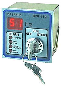
Контроллер DKG-112 Datakom является цифровым микропроцессорным устройством, предназначенным для ручного управления электрогенератором с двигателем внутреннего сгорания.
Обеспечивает контроль параметров напряжения и частоты, в случае отклонения автоматически отключает питание.
Система индикации аварийных ситуаций включается с задержкой в 4 секунды с момента включения электрогенератора.
В случае возникновения аварийной ситуации, происходит отключение двигателя, загорается соответствующий индикатор на панели устройства и активируется выход сигнализации аварийной ситуации.
Пределы корректной частоты генератора установлены от 30 до 57 Гц.
Задержка на отключение генератора при отклонении частоты за установленные пределы составляет 3 секунды.
Для работы напряжением питания 12 и 24 В. Используются различные модели устройств.
- Цифровая индикация частоты;
- Защита от перегрева двигателя;
- Защита от низкого давления масла
- защита от отклонения частоты генерируемого напряжения
- Дополнительный аварийный вход
- выход сигнализации аварийной ситуации
- Напряжение генератора: 40-250 В.
- Верхняя / Нижняя граница частоты: 57 — 30 Гц.
- DKG-112/12V 9-18 В.
- DKG-112/24V 17-33 В.
- Температурный диапазон / влажность: от -10 °С до +60 °С / 95%.
- Размеры и вес:72х72х70 mm / 400г.
- Материал корпуса: стальной корпус с поликарбонатной передней панелью.
- Соответствие (требования ЕС).
Контроллер DKG-105 Datakom
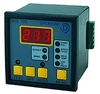
Панель ручного управления электрогенератором DKG-105 является цифровым микропроцессорным устройством, предназначенным для автоматического управления электрогенератором с двигателем внутреннего сгорания и обеспечивает все необходимые для этого функции.
Кроме того выполняет традиционные функции управления электростанцией и контроля параметров двигателя и генератора с выдачей сигнализаций критических и аварийных режимов.
В автоматическом режиме работ, устройство контролирует состояние 3х фаз сетевого напряжения и производит автоматический старт, остановку и переключение нагрузки генератора. В процессе работы генератора устройство контролирует внутренние защитные параметры и внешние аварийные входы.
Устройство содержит широкий спектр цифровых таймеров и пороговых триггеров.Программируемая конфигурация внутренних реле обеспечивает возможность работы с различными типами двигателей включая бензиновые. Все параметры могут быть изменены непосредственно с панели устройства.
На экране устройства могут быть отражены следующие параметры:
- Напряжение внешней сети для каждой из фаз L1-N, L2-N, L3-N
- Генерируемое напряжение L1-N;
- Частота генератора в Гц.
Устройство работает с двигателями, имеющими напряжение бортовой сети 12 и 24 В.
- автоматическое контроль состояние сетевого напряжения;
- режим тестирования и ручного управления;
- вывод на экран сетевых напряжений, генерируемого напряжения и его частоты;
- режим охлаждения двигателя перед отключением;
- возможность управлять свечами накала и воздушной заслонкой;
- контроль программируемого верхнего и нижнего порога сетевого/генерируемого напряжения;
- контроль программируемого верхнего и нижнего порога частоты генератора;
- программируемое время задержки сигнализации превышения и понижения частоты генератора;
- программируемое значение сигнализации верхнего предела напряжения аккумулятора;
- широкий спектр программируемых таймеров;
- блокировка режима программирования.
- Напряжение сети: 220/380 В.
- Напряжение генератора: 220-380 В.
- Частота генератора: 0 -100 Гц.
- Напряжение питания (по постоянному току): 9-3,3В 4-3,3В (в моменты запуска двигателя)
- Температурный диапазон и влажность: от — 10°С до + 60°С / 95%
- Размеры и вес: 72х72х76 mm / 240г
- Напряжение: 2% + 1В
- частота +/-0,5 Гц
- Материал корпуса: огнеустойчивая, высокотемпературная ABS (UL94-V0, 110 C)
- Соответствие (требования ЕС):
BE22 контроллер Bernini
Лицевая панель контроллера BE22 Bernini BE22 контроллер обеспечивает выполнение функции контроля параметров основной сети по одной из фаз (A.M.F) с выдачей сигнала на подключение нагрузки к исправному источнику электроэнергии.
Кроме этого выполняет традиционные функции управления электростанцией и контроля параметров двигателя и генератора с выдачей сигнализаций критических и аварийных режимов.
Контроллер построен на базе микропроцессора и обеспечивает точность измерений характерную современным цифровым устройствам.
Контроллер BE22 Bernini Пользовательский интерфейс включает 6 кнопок , 24 светодиодных индикатора, 4 -х позиционный цифровой дисплей.
Обмен информацией между контроллером и управляемыми устройствами осуществляется через 6 релейных выходов , 8 цифровых и 5 аналоговых входов.
К тому же контроллер имеет 28 программируемых параметров , счетчик моточасов, цифровую калибровку входных сигналов, 8 режимов отображения информации на дисплее и 14 стандартных сообщений.
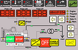
И наконец обеспечивает работу в 4-х основных режимах . Основные технические характеристики контроллера:
- Напряжение питания: Батарея питания электростанции 12-24V пост.тока / максимальное потребление 250mA
- Диапазон входного сетевого и генераторного напряжения: от 24V до 5OOV перем.тока
- Диапазон рабочих температур и влажность: от -30°C до +70°C , влажность 0-95% без образования конденсата.
- Установочный размер: 190 mm x 93 mm
- Максимальный ток релейных выходов постоянного тока: 4A постоянного тока (при соблюдении рекомендованного напряжения питания).
- Максимальный ток релейных выходов переменного тока: 8A переменного тока / при 250V (обязательно использовать плавкий предохранитель 1A)
BE46 (ВЕ23) — Многофункциональное устройство автозапуска для электростанций от BERNINI
BERNINI Универсальные устройства автоматизации и защиты двигателей и генераторных устройств.
Устройство заключено в корпус стандартного размера 96х96 мм и реализует все функции контроля и управления электростанцией в ручном или автоматическом режимах.
Устройство имеет 8 кнопок мембранного типа, 12 светодиодных индикаторов и 4 семисегментных индикатора на передней панели, создавая удобный интерфейс для пользователя.
Его программирование не представляет сложностей, и большинство параметров и сигнализаций индицируются на дисплее. ВЕ46 (ВЕ23) обеспечивает связь с аналоговыми датчиками и датчиком оборотов.
Измерение параметров включает измерение Vac, Iac, Vdc, kVA, kVar, kW, cosФ, Hz, часы, частоту вращения, давление масла, температуру охлаждающей жидкости.
Возможно программирование через ПК.
Основные технические данные:
- Установочные размеры ДхШ: 96х96
- Рабочий диапазон температуры: — 30 /+70° C
- Входы — 6, Выходы -6, Управляемые аналоговые выходы — 7
- Батарея питания электростанции 12-24V пост.тока / максимальное потребление 250mA
- Диапазон входного сетевого и генераторного напряжения: От 24V до 5OOV перем.тока
- Влажность 0-95% без образования конденсата.
- Максимальный ток релейных выходов постоянного тока: 4As постоянного тока (при соблюдении рекомендованного напряжения питания).
- Максимальный ток релейных выходов переменного тока: 8A переменного тока / при 250V (обязательно использовать плавкий предохранитель 1A)
Источник
Ве23а gen set control схема подключения
По причине проведения политики постоянного улучшения продукции, информация, упомянутая в данном руководстве, может быть изменена без предупреждения.
Бернини Дизайн SRL гарантирует , что Ве-46 не содержит дефектов в материалах и конструкции и безотказную работу в течении 3 лет с момента поставки . Условия исполнения гарантийных обязательств соответствуют международной гарантии.
1. Описание передней панели.
2. Инструкции по работе в ручном режиме
2.2 Ручной останов
3. Инструкция по работе в автоматическом режиме
3.1 Выбор режима автоматической работы
3.2 Использование возможности дистанционного запуска
3.3 Использование функции задержанного пуска.
4. Инструкция по режиму «выключено»
5. Описание сигнализаций
6. Передняя панель и схема подключения.
1. 1Описание передней панели.
Передняя панель Ве-46 включает 8 нажимных кнопок:
^ и ^ чтобы выбирать меню ALARM –Сигнализаций , Program- Программирования,
Power-Мощности , V/A/Hz/h – Напряжения /Тока/Частоты/Моточасов, Engine-Двигателя.
чтобы просматривать информацию внутри меню.
АСК чтобы подтверждать сигнализацию и отображать имя параметра.
AUTO-MAN , START-ON, STOP-OFF чтобы управлять двигателем и рабочими режимами.
^ 1.2 Индикаторные лампы.
Be-46 содержит 12 индикаторных ламп выполненных из цветных светодиодов.
OIL –красная – сигнализация по давлению масла.
TEMPERATURE – красная – сигнализация по высокой высокой температуре охлаждающей жидкости.
^ BATTERY- красная – высокое или низкое напряжение батареи.
FUEL- красная – сигнализация по низкому уровню топлива.
EXT – красная – сигнализация дистанционного останова.
SPEED –красная – сигнализация по превышению оборотов.
^ AUTO- зеленая – отображает включение автоматического режима.
ALARM- красная – отображает включение меню . содержащее информацию о сигнализациях.
PROGRAM –желтый – отображает включение режима программирования.
POWER-желтый – отображает включение режима мощность.
^ V/A/Hz/h – желтый –отображает включение меню электрических параметров.
ENGINE- желтый –отображает выбор меню двигатель.
Детальная информация о сигнализациях в разд.5.
Дисплей имеет четырехпозиционный буквенно-цифровой индикатор и пять светодиодов, характеризующих включение режимов работы.
Каждое меню отображается включением своего желтого светодиода.
^ 1.4 Меню ENGINE –двигатель.
Меню двигателя выдает оперативные сообщения и измерения параметров двигателя.
Включение меню сопровождается горением желтого индикатора , который мерцает при работе двигателя. Кнопками выбираются оперативные сообщения либо измерения параметров двигателя.
^ Оперативные сообщения . Ве-46 обновляет и снимает сообщения автоматически в соответствии с внутренней работой устройства.
[ t.on] AMF вход активирован Ве-46 ожидает истечение задержки запуска.
[t.off] AMF вход отключен Ве-46 отсчитывает задержку пред остановом.
[Cool] Контактор генератора отключен Ве-46 отсчитывает время охлаждения.
[Stop] Ве-46 отсчитывает время запитывания стоп-соленоида.
[Heat] Ве-46 отсчитывает время предпускового подогрева.
[TgEn] Индицирует время прогрева двигателя пред включением контактора.
[Sta] Сообщение информирует о том . что запитан выход стартера.
[load] Сообщение информирует . что генераторный контактор включен.
[—] Ве-46 в ожидании , все процедуры исполнены.
[Cr.de.] Сообщение перед пуском двигателя.
[Test] Активирован тест двигателя.
Измерения параметров двигателя.
Каждый раз при нажатии кнопок кратковременно загорается имя параметра и затем его величина. Нажатием кнопки АСК можно вернуть имя параметра на дисплей.
[rPM] – отображение оборотов двигателя до 4000 об/мин.
[OIL]- индикация давления масла до 20 Бар.
[tEmP]-температура двигателя до 200С.
[batt]- напряжение батареи до 36В.
[Fuel]- индикация уровня топлива.
^ 1.5 Меню PROGRAM – программирования.
Список программируемых параметров приводится ниже.
Первый символ , заключенный в скобки , отображает название параметра. С правой стороны указаны заводские значения параметров , которые могут быть модифицированы производителем генераторных установок.
^ Мы рекомендуем записать те параметры , которые отличаются от заводских установок , это поможет в случае сбоев в Ве-46.
Различные временные интервалы.
(horn) 20 сек. Время работы выхода сирены от 5 до 59 сек и от 1 до 15мин. Свыше 15 код обеспечивает ручной сброс выхода сигнализации (#27) и пользователь должен нажать АСК кнопку, чтобы сбросить выход сирены;
(t.on) 10 сек. Задержка запуска устройства 0 сек без задержки от 0 до 59 сек и от 1 до 15 мин. Этот таймер управляет задержкой запуска по AМF вход 2′;
(t.off) 10 сек. Задержка остановки двигателя 0 сек без задержки до 60 сек и от1 мин до 9 мин. Этот таймер управляет остановом по AМF вход 2′;
(сооl) 10 сек. Время охлаждения перед выключением 0 сек без задержки до 59 сек и от 1 до 15 мин. Эта задержка обеспечивает некоторую термостабилизацию частей двигателя;
(stop) 10 сек. Запитка стопового соленоида от 10 до 99 сек. Таймер чтобы управлять
выходом #31 стопового соленоида;
(heat) 0 сек Обеспечение подогрева от 1 мин до 99 мин. Таймер, чтобы контролировать выход #32 подогрев. Код 0 делает таймер неактивным.
(t.gen) 10 мин. Двигатель запущен генератор без нагрузки. От 0 до 59 сек. И от l до 15 мин. это время позволяет прогреть генераторное устройство до закрытия выходного контактора.
Различные защиты и установки.
(Ct r) 500 А Предел токового трансформатора от 0А до 2000А шаг изменения 10 А . От 2000 до 9000А шаг изменения 100А;
(Hi 1) — Точка превышения тока устройства. — мониторинг отключен. от 10А до 2000 А шаги изменения 10А и 100А от 2000 до 9000А;
(Lo U) 200V Заниженное напряжение от lv до 999 v ,— монитор выключен;
(Hi U) 420 V Превышение напряжения от 0v до 999v;
(PНAS) 3рh/ Выбор количества фаз: 3 фазы (3-ph) или 1 фаза (1-ph);
(Vас r) 1. Фактор считывания напряжения Хl или Х2;
(Hi р) — kV А Предел мощности, — монитор выключен или от 10 до 9900 kVA.
Защиты по скорости и частоте.
(Lo Fr) 45 Нz. Занижена частота от 1 до 99 Нz. — монитор выключен;
(Нi Fr) 55 Нz. Завышена частота 0-98 нz монитор выключен;
(Lo Sp) — Занижение скорости об/мин. от 10 до 4000, — монитор выключен;
(Hi Sp) — Завышение скорости об/мин. от 10 до 4000, — монитор выключен;
(Сг Sp) 300. Отсоединение стартера об/мин. от 300 до 800, — монитор выключен;
(Pic R) — Число от 1 до 500 зубцов маховика, — монитор выключен.
Установка предупреждений по работе двигателя.
(Lo Рг) — Предупреждение низкое давление масла от 0.1 до 20.0 Ваr, —монитор выключен;
(Hi С) —о Предупреждение по температуpе от 1 до 199 °С, — монитор выключен.
Программируемые выходы.
(Out 1) О . Выход l’ (#29) .Выбор сигнализации кодируется от 0 до 13 см. ниже имеющуюся опцию;
(Out 2) О. Выход 2′ (#30). Выбор сигнализации кодируется от 0 до 13 см. ниже имеющуюся опцию;
2 Флаг статуса работающего двигателя;
^ 3. Предварительная сигнализация по маслу/температуре;
4. Сигнализация выключателя давления масла / двигатель остановлен;
5. Сигнализация выключателя температуры по входу 1′;
6. Сигнализация о высоком/низком напряжении батареи;
^ 7. Предварительная сигнализация по топливу, останов двигателя;
8. Вход 3′ внешний останов, остановка двигателя;
9. Сигнализация по скорости и по частоте, остановка двигателя;
10. Сигнализация по напряжению генератора, остановка двигателя;
^ 11. Сигнализация по перегрузке , остановка двигателя;
12. Отказ при запуске, остановка двигателя;
13.Сигнализация повреждения ремня, остановка двигателя.
Программируемые входы:
(In 1) N.O. Действие выключателя температуры по входу l’ , нормально открыт или закрыт;
(In 2) N.O. Действие выключателя AМF вход 2′ , нормально открыт или закрыт; (In 3) N.O. Действие выключателя внешний останов по входу 3′ , нормально открыт или закрыт;
(In 4) N.O. Действие выключателя дополнительная сигнализация по входу 4′, нормально открыт или закрыт. Для того чтобы останавливать двигатель или режим входа по топливу, чтобы обеспечить связь с датчиком уровня топлива.
Связь топливного датчика.
Если режим входа по топливу выбран, то появятся следующие дополнительные параметры:
(FUEL) — Установка предупреждения низкого уровня топлива от 1 до 25%,-монитор отключен;
(F 00) 00%. Точка калибровки уровня топлива в Ом — 320 (от 7 до 483 Ом);
(F 25) 25%. Точка калибровки уровня топлива в Ом — 200 (от 7 до 483 Ом);
(F 50) 50%. Точка калибровки уровня топлива в Ом — 110 (от 7 до 483 Ом);
(FI00) 99%. Точка калибровки уровня топлива в Ом — 007 (от 7 до 483 Ом).
диапазон в Ом должен быть от 7 до 483 Ом. Другие величины могут быть обеспечены комбинациями внешних резисторов.
Связь с датчиком давления.
Шесть точек взаимосвязи Ваг (до 20) и Ом (до 483). В скобках отображены величины и сообщения.
| ^ Сообщение Значение Величина | Сообщение Значение Величина | ||||
| (r1 р) | Ом | 10 | Рl | Ваг | 0 |
| (г2 р) | Ом | 51 | р2 | Ваг | 2 |
| (г3 р) | Ом | 86 | р3 | Ваг | 4 |
| (г4 р) | Ом | 122 | р4 | Ваг | 6 |
| (г5 р) | Ом | 152 | р5 | Ваг | 8 |
| (гб р) | Ом | 180 | р6 | Ваг | 10 |
| Связь с датчиком температуры. | |||||
| ^ Шесть точек связи между температурой и величиной в Ом * — отображает | |||||
| заводские величины. Диапазон в Ом должен быть от 8 до 483 Ом. Другие | |||||
| величины могут быть получены в комбинации внешних резисторов. Величины | |||||
| температуры от О до 200 С. | |||||
| Сообщение | Значение Величина | ^ Сообщение Значение | Величина | ||
| (гl Т) | Ом | 19 | Т1 | С | 128 |
| (г2 Т) | Ом | 26 | Т2 | С | 115 |
| (гЗ Т) | Ом | 95 | Т3 | С | 70 |
| (г4 Т) | Ом | 287 | Т4 | С | 40 |
| (г5 Т) | Ом | 287 | Т5 | С | 40 |
| (гб Т) | Ом | 287 | Тб | С | 40 |
^ 1.6 Меню POWER -мощность.
Это меню показывает полную мощность (UA) величина в kVА единицах ( от 0 до 9990 kVА) к тому же активную мощность (Act.p) от 0-9990 kVА, реактивная мощность (UAr) от 0-9990 kVА и фактор мощности (PF) от 0 до 1.0.
^ 1.7 Меню V/A/Hz/h- электрических параметров.
Это меню показывает следующие параметры (UAC) 3-х фазное напряжение индицируется горизонтальными тире на левой позиции дисплея: верхнее тире — фазы L 1 и L2 в диапазоне 80 Vас до 500 Vас ( 1000 Vас в соответствии с (Vас, r)). Среднее тире: фаза L2 и L3. Нижнее тире L1 и L3.
^ Ве 23 способно читать напряжение в соответствие сХ1 и X2 фактором (см. параметр Vас, r).
Если сделан выбор одной фазы (phas), чтение означает напряжение L1 и N.
(Сurr) Измерение тока в пределах четырехпозиционного поля до 9990 Аас и указывает только ток в одной фазе.
(Fr Eq) Частота имеет 0.lНz разрешение (от 0 до 99.0).
(Hour) Счетчик часов может записать до 9990 часов с одночасовым разрешением на дисплее и 5-минутным разрешением на счетчике внутренней памяти. В любой момент нажатием кнопки «АСК» , название параметра размещается на дисплее чтобы помочь пользователю.
(U L-n) –3-х фазное генераторное напряжение поочередно по одной фазе с помощью тире в правой части дисплея.
^ 1.8 Меню ALARM- сигнализаций.
Это меню перечисляет коды сигнализаций, которые не имеют индикации на светодиоды передней панели.
Если одна из следующих сигнализаций активируется, запитывается красный светодиод «АLARМ» .Он будет мигать чтобы привлечь внимание пользователя. Он прекратит мигать после очистки сигнализации описанной в разделе 6.
(Hi L) — превышение тока, останов (Нi Р) — полная мощность, останов
(Lo Р2) — предупреждение низкое давление масла (F Р2) –предупреждение
(Hi С) — предупреждение по температуре (F С) — предупреждение отказ
(Hi F2)-превышение частоты, останов. (Lo f2)-низкая частота
(F Аl) -генератор отказ, останов. (Вelt) -разрыв ремня
(F Pi) -отказ датчика оборотов (F Cr) -отказ при запуске,
(Lo Sp)- низкая скорость ,останов. (Нi U)-превышение
(Lo U) -низкое напряжение, останов. (Fuel) -низкий уровень
Внимание: рекомендуется проверить , что заводская программа удовлетворяет характеристикам двигателя и генератора которые вы используете.
Первоначальные установки.
Нажмите кнопку START/ON в течение 2-х сек. Тест ламп будет происходит в течение 3-х сек. В конце светодиод AUТO/МAN не будет светиться индицируя ручной режим работы.
Дисплейное меню автоматически переходит в положение ENGINE давая возможность показать рабочие сообщения. Четыре тире сообщают о том что Ве 46 находится в режиме ГОТОВ.
^ В случае сомнения воздействие на кнопку АСК выведет на дисплей описание сообщения параметра выведенного на дисплей.
Сейчас пользователь может выбрать;
— установить Ве 46 в OFF путем нажатия кнопки STOP/OFF /
— установить Ве46 в AUTO нажатием кнопки AUTO/MAN/
— запустить или остановить двигатель используя START/ON и STOP/OFF кнопки.
— Просмотреть 5 видов меню 4-х позиционного дисплея.
Нажмите кнопку START до тех пор пока не начнется запуск двигателя. Для того чтобы обеспечить этот цикл память сигнализаций должна быть пустой. Чтобы информировать о наличии записей сигнализаций существует красный светодиод ALARМ. Все сигнализации на передней панели должны быть погашены. Чтобы очистить память от сигнализации нажмите OFF и затем повторите первоначальные установки. Если производится STOP цикл подождите конца этого цикла или нажав кнопку STOP/OFF очистите STOP цикл.
^ Сообщение(SТА) отображается во время цикла раскрутки двигателя в меню ENGINE .
Желтый светодиод мерцает ENGINE если один источник запущенного двигателя опознается как правильный. В этот момент любые воздействия на кнопку START/ON не имеют эффекта.
Если функция подогрева подключена в меню конфигурации генераторного устройства (НЕАТ) сообщение появится во время цикла подогрева. Как мера безопасности топливный соленоид отключается если не произошел правильный пуск в течение 20 сек. Или если пользователь нажал кнопку так быстро когда двигатель еще не готов к запуску и забыл использовать STOP/OFF кнопку.
В ручном режиме все сигнализации контролируются кроме «занижена частота» и «занижено напряжение».
^ 2.2 Ручной останов.
Нажмите STOP/OFF до появления сообщения (STOP) в меню ENGINE. Топливный соленоид отключен, а стоповый соленоид срабатывает в запрограммированное время.
В конце STOP цикла дальнейшее воздействие на кнопку STOP/OFF включает Ве 46 в режим OFF . Этот режим малого потребления энергии индицируется посредством децимальной точки возле самой малой цифры дисплея.
^ 3.0 Инструкция по работе в режиме AUТO.
Внимание проверьте , что заводская программа
удовлетворяет характеристикам генератора.
3.1 Автоматический режим.
A) Нажмите START/ON кнопку в течение 2-х сек. Будет иметь место тест
ламп в течение 2-х сек. в конце светодиод AUТO/МAN гореть не будет, что означает ручной режим. Меню автоматически перейдет в меню ENGINE для
отражения рабочих сообщений.
Б) Нажмите AUTO/МAN в течение одной сек. Как подтверждение включения
автоматического режима зеленый светодиод в верхней части кнопки загорится. Сейчас старт и стоп устройства связан с выключателем дистанционного пуска останова или компьютером.
Если существует одна или более сигнализаций внутренний контроль Ве 46 запрещает переход из ручного режима в автоматический. Убедитесь, что все сигнализации сняты должным образом. Если память сигнализаций не пуста красный светодиод АLARМ мигает или один из светодиодов сигнализации горит.
^ 3.2 Использование возможности дистанционного запуска.
Когда выключатель дистанционного пуска –останова становиться активным , Ве 46 начинает запуск
двигателя и затем переведет нагрузку на генератор .
Когда дистанционный стоп контакт открывается, нагрузка предварительно
переводится на сеть и двигатель останавливается.
^ 3.3 Использование функции задержанного пуска
Пользователь может запустить и остановить устройство заземлением на корпус AMF входа. Этот вход имеет приоритет над дистанционным стартом и включает важные временные интервалы такие как запуск с задержкой, подогрев, охлаждение, останов с задержкой. При пуске отображается (t.on) , при останове (t.off).
^ 3.4 Останов устройства в режиме АUTO.
В любой момент пользователь может остановить генераторное устройство.
Самый простой путь перевести в ручной режим и нажать кнопку STOP/OFF/
Когда система перейдет в режим MAN, все автоматические запросы, сделанные на входные клеммы, очищаются. Использование кнопки STOP/OFF активизирует сигнализацию ЕХТ и пользователь должен будет снять эту сигнализацию перед следующим пуском Ве 46.
^ 4.0 Режим OFF отображается децимальной точкой и приводится В действие нажатием кнопки STOP/OFF/.
5.0 Описание сигнализаций.
Сигнализации индицируются посредством красных светодиодов и особым сообщением на дисплее в меню ALARМ .
Красный светодиод мигает до тех пор пока оператор не нажмет кнопку АСК и затем останется гореть. Выход сигнализации — о6есточивается нажатием кнопки АСК или посредством истечения времени параметра СИРЕНА.
^ Если код (cont) запрограммирован на (horn) выход сигнализация не о6есточивается автоматически.
Сообщение дисплея и светодиоды очищаются только посредством кнопки STOP/OFF. Сигнализацию можно очистить только при неработающем двигателе (желтый светодиод ENGINE не мигает).
^ Сообщение Err отображает отказ процедуры записи или самой памяти. Пользователь должен следовать следующим путем:
— Нажмите кнопку АСК, чтобы очистить сигнализацию.
— Введите режим программирования .
— Проверьте установки всех параметров в соответствие с первоначальным программированием.
— Сохраните установки как описано в разделе программирование.
— Если Err сообщение не исчезло, сдайте блок в ремонт.
6.0 Передняя панель и схема подключения
Источник
80,00 $ — 100,00 $/ шт. |1 шт./шт.(Мин. заказ)
- Преимущества:
- Быстрый возврат средств по заказам на сумму менее 1000 USDПолучить сейчас
Сведения о покупке
Защита с помощью
Транспортировка:
Связаться с поставщиком для согласования деталей доставки
Для вас Гарантия своевременной отправки
Платежи:
Шифрование и повышенная безопасность платежей Подробнее
Возврат товаров и возмещение средств
Для невыполненных заказов, недостач и других проблем с товаром Подробнее
Для получения информации касательно цен, индивидуальных заказов и других вопросов:

Manufacturer,Trading Company,Agent
 CN
CN
7