
PT
RU
DE
PL
IT
NL
GR
SE
DK
FI
IMPORTANTE: Leia este documento
antes de utilizar o produto. Deseja mais
informação acerca deste produto?
Consulte o verso deste folheto.
ВНИМАНИЕ: Прочитайте этот
документ перед использованием
устройства. Дополнительную
информацию об устройстве вы
найдете на обратной стороне этого
буклета.
WICHTIG: Lesen sie dieses Dokument,
bevor Sie das Produkt verwenden.
Weitere Informationen zu diesem
Produkt finden Sie auf der Rückseite
dieser Broschüre.
WAŻNE: Przeczytaj niniejszy dokument
przed przystąpieniem do użytkowania.
Szczegółowe informacje dotyczące tego
produktu znajdziesz na odwrocie broszury.
IMPORTANTE: Prima di utilizzare
il prodotto, leggere il presente
documento. Desiderate ricevere
maggiori informazioni su questo
prodotto? Vi rimandiamo al retro del
presente libretto.
BELANGRIJK: lees dit document goed
door voordat u het product in gebruik
neemt. Wilt u meer informatie over dit
product? Kijk dan op de achterpagina
van dit boekje.
ΣΗΜΑΝΤΙΚΟ: Διαβάστε αυτό το έντυπο
πριν από τη χρήση του προϊόντος.
Θέλετε περισσότερες πληροφορίες για
αυτό το προϊόν; Ανατρέξτε στην πίσω
πλευρά του φυλλαδίου.
VIKTIGT: Läs det här informationen
innan produkten används. Önskas mer
information om produkten? Se baksidan
på den här broschyren.
VIGTIGT! Læs dette dokument, før
produktet tages i brug. Vil du have flere
oplysninger om produktet? Se bagsiden
af denne folder.
TÄRKEÄÄ: Lue tämä asiakirja ennen
tuotteen käyttöä. Haluatko lisätietoja
tuotteesta? Katso vihon takasivu.
Instruções de
funcionamento/
segurança
Инструкция по
эксплуатации
и технике
безопасности
Bedienungs-/
Sicherheits-
hinweise
Wskazówki
obsługi/
bezpieczeństwa
Istruzioni di
funzionamento /
sicurezza
Bedienings-/
veiligheids-
voorschriften
Οδηγίες
λειτουργίας/
ασφαλείας
Drifts-/säkerhets-
instruktioner
Betjenings-
og sikkerheds-
instruktioner
Käyttö- ja
turvallisuusohjeet
www.behringer.comA50-00000-00969
X1222USB
X1832USB
Introduction
FBQ Feedback Detection System
The FBQ Feedback Detection System, integrated into the graphic equalizer, is one of the most outstanding characteristics of this mixing console. This ingenious circuitry lets you immediately recognize and eliminate feedback frequencies. The FBQ Feedback Detection System uses the LEDs in the frequency band faders of the graphic EQ to indicate the critical frequencies. This way, what once used to be a labor-intensive search for feedback frequencies is now an activity that even a child could master.
The microphone channels feature high-end XENYX Mic Preamps that compare well with costly outboard preamps in terms of sound quality and dynamics and boast the following features:
- 130 dB dynamic range for an incredible amount of headroom
- A bandwidth ranging from below 10 Hz to over 200 kHz for crystal-clear reproduction of even the finest nuances
- The extremely low-noise and distortion-free circuitry guarantees absolutely natural and transparent signal reproduction
- They are perfectly matched to every conceivable microphone with up to 60 dB gain and +48 volt phantom power supply
- They enable you to use the greatly extended dynamic range of your 24-bit/192 kHz HD recorder to the full, thereby maintaining optimal audio quality
«British EQ»
The equalizers used for the XENYX Series are based on the legendary circuitry of top-notch consoles made in Britain, which are renowned throughout the world for their incredibly warm and musical sound character. Even with extreme gain settings these equalizers ensure outstanding audio properties.
Multi-effects processor
Additionally, your XENYX mixing console has an effects processor with 24-bit A/D and D/A converters included, which gives you 16 presets producing first-class reverb, delay and modulation effects plus numerous multi-effects in excellent audio quality.
The XENYX mixing consoles are equipped with a state-of-the-art switched-mode power supply (SMPS). Unlike conventional circuitry an SMPS provides an optimum supply current regardless of the input voltage. And thanks to its considerably higher efficiency a switched-mode power supply uses less energy than conventional power supplies.
We would like to draw your attention to the fact that extreme volumes may damage your hearing and/or your headphones or loudspeakers. Turn the MAIN MIX faders and the PHONES control in the main section fully down before you switch on the unit. Always be careful to set the appropriate volume.
General mixing console functions
A mixing console fulfils three main functions:
- Signal processing:
Preamplification
Microphones convert sound waves into voltage that has to be amplified several-fold; then, this voltage is turned into sound that is reproduced in a loudspeaker. Because micro phone capsules are very delicate in their construction, output voltage is very low and therefore susceptible to interference. Therefore, mic signal voltage is amplified directly at the mixer input to a higher signal level that is less prone to interference. This higher, interference-safe signal level has to be achieved through amplification using an amplifier of the highest quality in order to amplify the signal and add as little noise to it as possible. The XENYX Mic Preamp performs this role beautifully, leaving no traces of noise or sound coloration. Interference that could take place at the preamplification level could affect signal quality and purity, and would then be passed on to all other devices, resulting in inaccurate sounding program during recording or playback.
Level-setting
Signals fed into the mixer using a DI-box (Direct Injection) or the output of a sound card or a keyboard, often have to be adjusted to the operating level of your mixing console.
Frequency response correction
Using the equalizers found in each channel strip, you can simply, quickly and effectively adjust the way a signal sounds.
Effects mixing
In addition to the effects processor contained in your mixer, using the insert connectors on the mono channels and both aux busses lets you insert additional signal processors into your signal path. - Signal distribution:
Individual signals adjusted at each channel strip are laid out at the aux sends and returns, and are either fed into external effects processors or fed back to the internal effects processor. Then, the signals are brought back into the main mix either via the aux return connectors or via direct internal wiring. The mix for the on-stage musicians is also created using the aux sends (monitor mix). Similarly, for example, signals for recording equipment, power ampli fiers, headphones and 2-track outputs can also be taken. - Mix:
All other mixing console functions fall under this vital category. Creating a mix means primarily adjusting the volume levels of individual instruments and voices to one another as well as giving them the appropriate weight within the overall frequency spectrum. Likewise, you’ll have to sensibly spread individual voices across the stereo image of a signal. At the end of this process, adjusting the level of the entire mix to other equipment in the signal path is required (e.g. recorder/crossover/amplifier). The interface of BEHRINGER mixing consoles is optimized for these tasks, enabling you to easily keep track of the signal path.
The user’s manual
The user’s manual is designed to give you both an overview of the controls, as well as detailed information on how to use them. In order to help you understand the links between the controls, we have arranged them in groups according to their function.
Before you get started
Shipment
Your mixing console was carefully packed in the factory to guarantee safe transport. Nevertheless, we recommend that you carefully examine the packaging and its contents for any signs of physical damage, which may have occurred during transit.
- If the unit is damaged, please do NOT return it to us, but notify your dealer and the shipping company immediately, otherwise claims for damage or replacement may not be granted.
Initial operation
Be sure that there is enough space around the unit for cooling purposes and to avoid over-heating. Please do not place your mixing console on high-temperature devices such as radiators or power amps. The console is connected to the mains via the supplied power cable. The console meets the required safety standards. Blown fuses must only be replaced by fuses of the same type and rating.
- Please note that all units must be properly grounded. For your own safety, you should never remove any ground connectors from electrical devices or power cables, or render them in operative.
- Please ensure that only qualified people install and operate the mixing console. During installation and operation, the user must have sufficient electrical contact to earth, otherwise electrostatic discharges might affect the operation of the unit.
Online registration
Please do remember to register your new BEHRINGER equipment right after your purchase by visiting behringer.com (alternatively behringer.de) and kindly read the terms and conditions of our warranty carefully.
Should your BEHRINGER product malfunction, our goal is to have it repaired as quickly as possible. To arrange for warranty service, please contact the retailer from whom the equipment was purchased. Should your BEHRINGER dealer not be located in your vicinity, you may directly contact one of our subsidiaries. Corresponding contact information is included in the original equipment packaging (Global Contact Information/European Contact Information). Should your country not be listed, please contact the distributor nearest you. A list of distributors can be found in the support area of our website (behringer.com).
Registering your purchase and equipment with us helps us process your repair claims quicker and more efficiently.
Thank you for your cooperation!
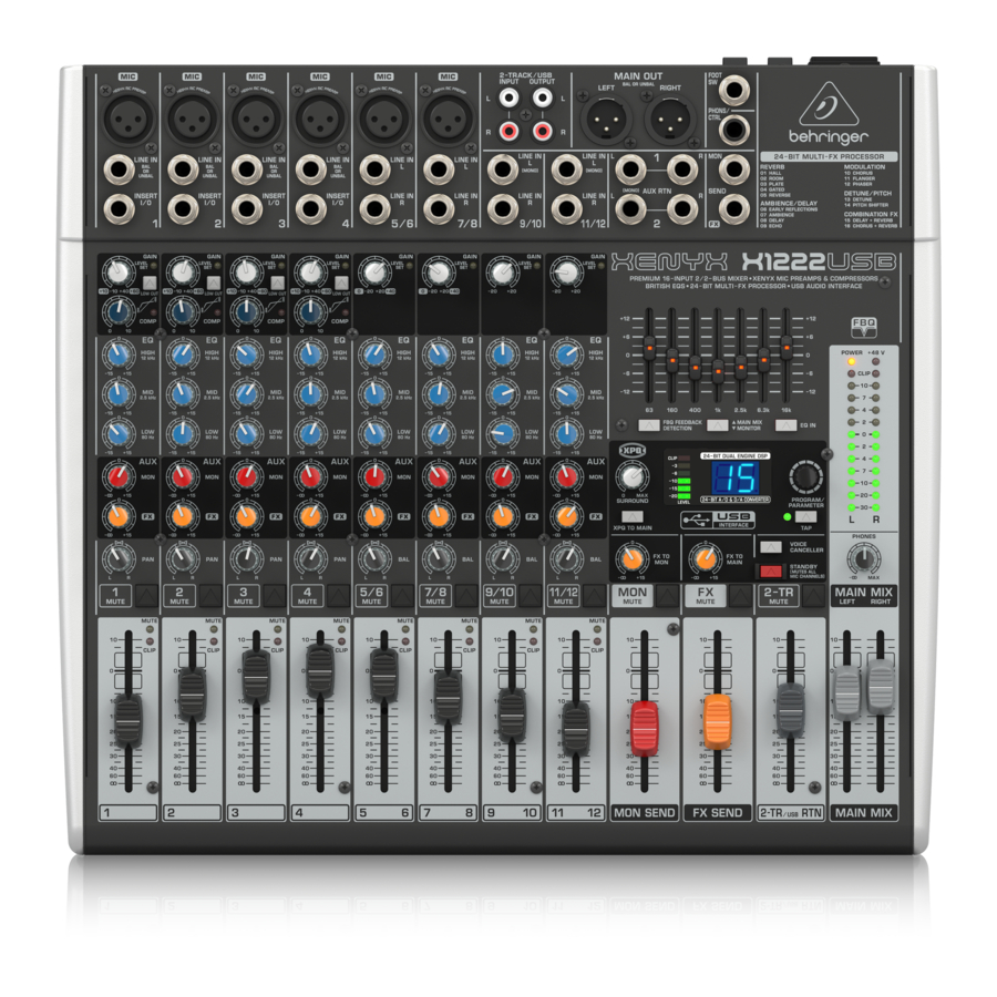
Control Elements and Connectors
This chapter describes the various control elements of your mixing console. All controls, switches and connectors will be discussed in detail.
Mono channels
Microphone and line inputs

MIC
Each mono input channel offers a balanced microphone input via the XLR connector and also features switchable +48 V phantom power supply for condenser microphones. The XENYX preamps provide undistorted and noise-free gain as is typically known only from costly outboard preamps.
- Please mute your playback system before you activate the phantom power supply to prevent switch-on thumps being directed to your loud speakers. Please also note the instructions in chapter 2.5 «Rear view of X1222USB».
LINE IN
Each mono input also features a balanced line input on a ¼» connector.
Unbalanced devices (mono jacks) can also be connected to these inputs.
- Please remember that you can only use either the microphone or the line input of a channel at any one time. You can never use both simultaneously!
INSERT
Insert points enable the processing of a signal with dynamic processors or equalizers. They are sourced pre-fader, pre-EQ and pre-aux send. Unlike reverb or other effects devices, whose signals are usually added to the dry signal, dynamic processors are most effective on the complete signal. In this case, aux send paths are a less-than-perfect solution. It is better to interrupt the signal path and insert a dynamic processor and/or equalizer. After processing, the signal is routed back to the console at precisely the same point it left. However, the channel signal path is interrupted only if a plug is inserted into the corresponding jack (stereo phone plug: tip = signal output; ring = return input). All mono input channels are equipped with inserts.
Inserts can also be used as pre-EQ direct outputs, without interrupting the signal path. To this end, you will need a cable fitted with mono phone plugs on the tape machine or effects device end, and a bridged stereo phone plug on the console side (tip and ring connected).
LOW CUT
The mono channels of the mixing consoles have a high-slope LOW CUT filter for eliminating unwanted, low-frequency signal components (80 Hz, 18 dB/octave).
GAIN
Use the GAIN control to adjust the input gain. This control should always be turned fully counter-clockwise whenever you connect or disconnect a signal source to one of the inputs.
The scale has 2 different value ranges: the first value range (+10 to +60 dB) refers to the MIC input and shows the amplification for the signals fed in there.
The second value range (+10 to -40 dB) refers to the line input and shows its sensitivity. The settings for equipment with standard line-level signals (-10 dBV or +4 dBu) look like this: While the GAIN control is turned all the way down, connect your equipment. Set the GAIN control to the external devices’ standard output level. If that unit has an output signal level display, it should show 0 dB during signal peaks. For +4 dBu, turn up GAIN slightly, for -10 dBV a bit more. Tweaking is done using the LEVEL SET LED.
LEVEL SET
This LED lights up when the optimum operating signal level is achieved. During normal use, this LED should only light up during signal peaks.
COMPRESSOR
Each mono channel features a built-in compressor which lowers the dynamic range of the signal and increases its perceived loudness. The loud peaks are squashed down and the quiet sections are boosted.
Turn the COMP knob clockwise to add more compression effect. The adjacent LED with light when the effect is engaged.
Equalizer
All mono input channels include a 3-band equalizer. All bands provide boost or cut of up to 15 dB. In the central position, the equalizer is inactive.
The circuitry of the British EQs is based on the technology used in the best-known top-of-the-line consoles and providing a warm sound without any unwanted side effects. The result are extremely musical equalizers which, unlike simple equalizers, cause no side effects such as phase shifting or bandwidth limitation, even with extreme gain settings of ±15 dB.
The upper (HIGH) and the lower band (LOW) are shelving filters that increase or decrease all frequencies above or below their cut-off frequency. The cut-off frequencies of the upper and lower band are 12 kHz and 80 Hz respectively. The mid band is configured as a peak filter with a center frequency of 2.5 kHz. Unlike shelving filters, the peak filter processes a frequency range that extends upwards and downwards around its middle frequency.
Aux sends (MON and FX)

Aux sends take signals via a control from one or more channels and sum these signals to a so-called bus. This bus signal is sent to an aux send connector and then routed, for example, to an active monitor speaker or an external effects device. The return from an external effects device can then be brought back into the console via the aux return connectors.
For situations that require effects processing, the aux sends are usually switched post-fader so that the effects volume in a channel corresponds to the position of the channel fader. If this were not the case, the effects signal of the channel would remain audible even when the fader is turned to zero.
When setting up a monitor mix, the aux sends are generally switched to pre-fader; i.e. they operate independently of the position of the channel fader. Both aux sends are mono, are sourced after the equalizer and offer up to +15 dB gain.
- If you press the MUTE switch of the respective channel, aux sends and returns (MON and FX) are not being muted.
MON
In the X1222USB, aux send 1 (MON) is wired pre-fader and is thus particularly suitable for setting up monitor mixes.
FX
The aux send labeled FX is for feeding external effects devices and is thus set up to be post-fader.
In the X1222USB, the FX send is routed directly to the built-in effects processor. To make sure that the effects processor receives an input signal, you shouldn’t turn this control all the way to the left (-oo). Don’t have the FX MUTE switch pressed, and you should also not have the FX SEND fader pulled down.
Pan, mute switch and channel fader

PAN
The PAN control determines the position of the channel signal within the stereo image. This control features a constant-power characteristic, which means the signal is always maintained at a constant level, irrespective of position in the stereo panorama.
MUTE
Use the MUTE switch to mute the channel. This means that the channel signal is no longer present in the main mix. However, the aux sends (MON and FX) remain active.
MUTE LED
The MUTE LED indicates that the relevant channel is muted.
CLIP LED
The CLIP LED lights up when the input signal is driven too high. In this case, lower apparent frequency increase on the channel EQ to avoid distortion. For example, lower the mids and the highs somewhat to emphasize the bass. If you don’t wish to change the EQ settings under any circumstances, try lowering the GAIN control somewhat (counterclockwise).
If you inserted an external effects processor via the insert connector (e.g. a dynamic processor), then you should also control its output signal level. It should not be higher than its input signal level (0 dB).
The channel fader determines the level of the channel signal in the main mix.
Attention: Since the aux path for the effect processor is connected post-fader, the channel fader has to be turned up in order to get this channel’s signal to the effects processor!
Stereo channels
Channel inputs

Each stereo channel features two line-level inputs on ¼» connectors for left and right channels. Channels 9/10 and 11/12 can also be used in mono if you only use the connector labeled «L.»
Both channels 5/6 and 7/8 feature an additional balanced XLR input for microphones with available +48 V phantom power.
All stereo channel strips have a GAIN control for level setting. In those channels in which a mic input is present in the channel, the GAIN control has two scales: just like in the mono channels, there is a 0 to +40 dB scale that shows the preamplification of the mic signal; the +20 to -20 dB scale shows the sensitivity for the corresponding input level that is applied to the line input.
Both inputs can also be used with balanced or unbalanced connectors.
Equalizer stereo channels
The equalizer of the stereo channels is, of course, stereo. The filter characteristics and crossover frequencies are the same as those of the mono channels. A stereo equalizer is always preferable to two mono equalizers if frequency correction of a stereo signal is needed. There is often a discrepancy between the settings of the left and the right channels when using separate equalizers.
Aux sends stereo channels
In principle, the aux sends of the stereo channels function in just the same way as those of the mono channels. As aux send paths are always mono, the signal on a stereo channel is first summed to mono before it reaches the aux bus.
Balance, mute switch and channel fader
BAL
The function of the BAL(ANCE) control corresponds to the PAN control in the mono channels.
The balance control determines the relative proportion between the left and right input signals before both signals are routed to the main stereo mix bus.
The MUTE switch, MUTE LED, CLIP LED and channel fader function in the same way as the mono channels.
Connector panel and main section
Whereas it was useful to trace the signal flow from top to bottom in order to gain an understanding of the channel strips, we now look at the mixing console from left to right. The signals are, so to speak, collected from one point on each of the channel strips and then routed to the main section all together.
Monitor send and FX send channels

A channel signal is routed to the MON(ITOR) send bus if the MON control is turned up on the corresponding channel.
MON SEND
The aux send control MON SEND acts as master control for the monitor bus and determines the level of the summed signal that is taken from the mixer via the MON SEND connector and that can for example be fed to an amplifier for monitor purposes.
Using the audio signal from this output, you can also feed a subwoofer if you don’t require stage monitors. To this end, you should implement a crossover in your signal path pre-subwoofer and pre-amplifier, so that only low frequencies are fed into the subwoofer. You can achieve the same effect by using the built-in graphical equalizer. Lower all frequencies above 160 Hz and assign the equalizer to «Monitor».
- When you use the MAIN MIX fader to reduce the overall volume, keep in mind that the subwoofer is still receiving a signal!
FX TO MON
You can use this control to insert an effects signal from the built-in effects processor to your monitor mix. Of course, to do this, your effects processor must first receive a signal, i.e. the FX controls in the channel strips must be turned up, and the FX SEND fader (see fig. 2.6) hast to be open.
MON MUTE
If the MON MUTE switch is pressed, the monitor bus is muted, i.e. there is no signal at the MON SEND connector.
FX SEND
The FX SEND fader determines the overall level of the effects bus. Both external effects processors (via the FX SEND connector) and the built-in processor only receive an input signal if this control is open.
FX TO MAIN
Use the FX TO MAIN control to feed the effects signal into the main mix.
If the control is turned all the way to the left, no effects signal can be heard.
FX MUTE
If the FX MUTE switch is pressed, the effects channel is muted, i.e. no signal is present at the FX SEND connector and the effects processor no longer receives an input signal.
Monitor send and FX send connector

MON SEND
Connect the input of your monitor power amp or an active monitor system here to make the monitor mix audible to the musicians on the stage. The signal mix is created using the channels’ MON controls.
FX SEND
The FX SEND connector outputs the signal you picked up from the individual channels using the FX controls. You can connect this to the input of an external effects device in order to process the FX bus’ master signal. Once an effects mix is created, the processed signal can then be routed from the effects device outputs back into the AUX RETURN connectors.
- If the connected effects processor receives no input signal, the FX MUTE switch is probably pressed and/or the FX SEND control is too low. This also goes for the built-in effects processor.
- Adjust your external effects processor to 100% wet (effects signal only), because the effects signal is added to the main mix along with the «dry» channel signals.
Aux return connectors

AUX RETURN 1
The AUX RETURN 1 connectors generally serve as the return path for the effects mix generated using the FX send. This is where you connect the output signal of the external effects device. If only the left connector is used, the aux return 1 automatically operates in mono.
- You can also use these connectors as additional line inputs.
AUX RETURN 2
The AUX RETURN 2 connectors are used exactly the same way as the AUX RETURN 1 connectors. If these connectors already function as additional inputs, you can route the effects signal back into the console via a different stereo channel, with the added benefit that the channel EQ can be used to adjust the frequency response of the effects return signal.
- In this instance, the FX control of the channel being used as an effects return should be turned fully counter-clockwise, otherwise feedback problems can occur!
CD/tape return channel, voice canceller and connection socket

This channel, intended especially for connecting stereo signal sources (CD players, DAT recorders or even sound cards) features a particularly practical feature: the VOICE CANCELLER.
VOICE CANCELLER
Here, you have a filter circuitry that lets you almost entirely remove the vocal portion of a recording. The filter is constructed in such a way that voice frequencies are targeted without majorly affecting the rest of the signal. Additionally, the filter seizes only the middle of the stereo image, exactly there where the vocals are typically located.
Possible applications for the Voice Canceller are obvious: you can very simply stage background music for Karaoke events. Of course, you can also do this at home or at your rehearsal room before you hit the stage. Singers with their own band can practice singing difficult parts using a complete playback from a tape player or a CD, thus minimizing rehearsal time.
STANDBY
If the STANDBY switch is pressed, all input channels with a mic connector (XLR connector) are muted. During breaks or stage conversion, you can prevent noise from entering the sound system via the microphones. Such noise can in the worst-case scenario even irreparably damage loudspeaker membranes. The cool thing about this is that the main mix faders can remain open, so that you can play music from a CD at the same time. Similarly, the faders for the muted channels can also remain in their position.
To bring in other sound sources, you can use the CD/tape inputs, stereo input channels 9 to 12 and the aux return inputs.
CD/TAPE MUTE
Using this switch, the input signal from the CD/tape inputs is muted.
CD/TAPE RET(URN)
This stereo fader assigns the input signal from the CD/tape inputs into the main mix.
CD/TAPE INPUT
The CD/TAPE INPUT RCA connectors are provided for connecting a 2-track machine (e.g. DAT recorder) or also a CD player. They can also be used as stereo line input.
Alternatively, the output signal of a second XENYX or BEHRINGER ULTRALINK PRO MX882 can also be connected. If you connect a hi-fi amplifier with a source selection switch to the CD/TAPE INPUT, you can easily switch between additional sources (e.g. cassette recorder, MD player, sound card etc.).
Using the voice canceller function, you can process all signals being brought into your mixing console via these connectors.
CD/TAPE OUTPUT
These connectors are wired pre graphic EQ and pre XPQ surround function.
They carry the main mix signal (unbalanced), effects mix included. Connect the CD/TAPE OUTPUT to the inputs of your recording device. If you wish to use your mixer solely for recording purposes, the main outputs are also an alternative.
Main mix, main out connectors and headphone connector
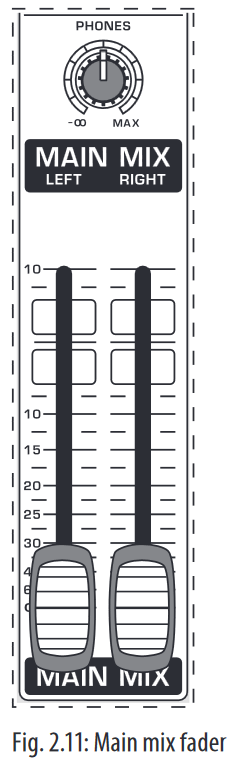
MAIN MIX
Use the high-precision quality faders to control the output level of the main mix.
MAIN OUT
The MAIN outputs carry the MAIN MIX signal and are on balanced XLR connectors with a nominal level of +4 dBu. Depending on how you wish to use your mixer and which gear you own, you can connect the following equipment:
Live PA systems:
A stereo dynamics processor (optional), stereo equalizer (optional) and the stereo power amplifier for full-range loud-speakers with passive crossovers.
If you wish to use multi-way loudspeaker systems without an integrated crossover, you have to use an active crossover and several power amplifiers. Often, limiters are already built into active crossovers (e.g. BEHRINGER SUPER-X PRO CX2310 and ULTRADRIVE PRO DCX2496). Active crossovers are implemented directly before the power amplifier, and they divide the frequency range into several segments that are first amplified in the amplifiers and then passed onto the corresponding loudspeakers.
Recording:
For mastering, using a stereo compressor such as the COMPOSER PRO-XL MDX2600 can be recommended. Use it to custom-tailor the dynamic characteristics of your signal to the dynamic range of the recording equipment you are using. The signal is in this case passed on from the compressor into the recorder.
PHONES
The PHONES control adjusts the volume of the headphones connected to the PHONS/CTRL connector. If you connect active monitors or an amplifier, use this connector to adjust the output signal level.
- We would like to draw your attention to the fact that extreme volumes may damage your hearing and/or your headphones or loudspeakers. Turn the MAIN MIX faders and the PHONES control in the main section fully down before you switch on the unit. Always be careful to set the appropriate volume.

PHONS/CTRL connector
You can connect headphones to this ¼» TRS connector. The connector can also be used for feeding active monitor loudspeakers (or an amplifier) in your control room. For this purpose, the signal is taken directly before it is passed on to the main mix faders.
Level meter and level setting
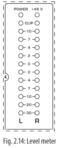
POWER
The blue POWER LED indicates that the device is switched on.
+48 V
The red «+48 V» LED lights up when the phantom power supply is switched on. The phantom power supply is necessary for condenser microphones and is activated using the corresponding switch on the rear of the device.
- Connect microphones before you switch on the phantom power supply. Please do not connect microphones to the mixer (or the stagebox/wallbox) while the phantom power supply is switched on. In addition, the monitor/PA loudspeakers should be muted before you activate the phantom power supply. After switching on, wait approx. one minute to allow for system stabilization.
LEVEL METER/CLIP
The high-precision level meter accurately displays the appropriate signal level.
LEVEL SETTING:
When recording to a digital device, the recorder’s peak meter should not exceed 0 dB. This is because, unlike analog recordings, slightly excessive levels can create unpleasant digital distortion.
When recording to an analog device, the VU meters of the recording machine should reach approx. +3 dB with low-frequency signals (e.g. kick drum). Due to their inertia VU meters tend to display too low a signal level at frequencies above 1 kHz. This is why, for example, a Hi-Hat should only be driven as far as -10 dB. Snare drums should be driven to approx. 0 dB.
- The peak meters of your XENYX display the level virtually independent of frequency. A recording level of 0 dB is recommended for all signal types.
USB input/output

The XENYX mixer line has built-in USB connectivity, allowing stereo signals to be sent to and from the mixer and a computer. The audio sent from the mixer to a computer is identical to the MAIN MIX. Audio being sent to the mixer from a computer can be routed to the main mix with the 2-TR/USB TO MAIN button.
Connect the USB type B plug into the USB jack on the mixer, and the other end into a free USB port on your computer. There are no required drivers, but we recommend that PC users install the included ASIO driver. The driver can also be downloaded from behringer.com.
Graphic 7-band equalizer

The graphic stereo equalizer allows you to tailor the sound to the room acoustics.
FBQ FEEDBACK DETECTION
The switch turns on the FBQ Feedback Detection System. It uses the LEDs in the frequency band faders to indicate the critical frequencies. On a per-need basis, lower the frequency range in question somewhat in order to avoid feedback. The graphic stereo equalizer has to be turned on in order to use this function.
- Logically, at least one (ideally several) microphone channels have to be open for feedback to occur at all!
Feedback is particularly common when stage monitors («wedges») are concerned, because monitors project sound in the direction of microphones. Therefore, you can also use the FBQ Feedback Detection for monitors by placing the equalizer in the monitor bus (see MAIN MIX/MONITOR).
EQ IN
Use this switch to activate the graphic equalizer. When activated, the fader LEDs will illuminate.
MAIN MIX/MONITOR
This toggles the graphic equalizer between the main mix and the monitor mix. With the switch up (not depressed), the equalizer is active in stereo on the main mix, and inactive on the monitor mix.
When the switch is depressed the equalizer is active in mono on the monitor mix, and inactive on the main mix.
Rear view of X1222USB

FUSE HOLDER/IEC MAINS RECEPTACLE
The console is connected to the mains via the cable supplied, which meets the required safety standards. Blown fuses must only be replaced by fuses of the same type and rating. The mains connection is made via a cable with IEC mains connector. An appropriate mains cable is supplied with the equipment.
POWER
Use the POWER switch to power up the mixing console. The POWER switch should always be in the «Off» position when you are about to connect your unit to the mains.
To disconnect the unit from the mains, pull out the main cord plug. When installing the product, ensure that the plug is easily accessible. If mounting in a rack, ensure that the mains can be easily disconnected by a plug pull or by an all-pole disconnect switch on or near the rack.
Attention: The POWER switch does not fully disconnect the unit from the mains. Unplug the power cord completely when the unit is not used for prolonged periods of time.
PHANTOM
The PHANTOM switch activates the phantom power supply for the XLR microphone inputs, which is required to operate condenser microphones. The red +48 V LED lights up when phantom power is on. As a rule, dynamic microphones can still be used with phantom power switched on, provided that they are wired in a balanced configuration. In case of doubt, contact the microphone manufacturer!
- Connect microphones before you switch on the phantom power supply. Please do not connect microphones to the mixer (or the stagebox/ wallbox) while the phantom power supply is switched on. In addition, the monitor/PA loudspeakers should be muted before you activate the phantom power supply. After switching on, wait approx. one minute to allow for system stabilization.
You must never use unbalanced XLR connectors (PIN 1 and 3 connected) on the MIC input connectors if you want to use the phantom power supply.
SERIAL NUMBER
Please note the important information on the serial number.
Digital Effects Processor and XPQ Surround Function
Digital effects processor

24-BIT MULTI-EFFECTS PROCESSOR
Here you can find a list of all presets stored in the multi-effects processor. This built-in effects module produces high-grade standard effects such as reverb, chorus, flanger, delay and various combination effects. The integrated effects module has the advantage of requiring no wiring. This way, the danger of creating ground loops or uneven signal levels is eliminated at the outset, completely simplifying the handling.
These effect presets are designed to be added to dry signals. If you move the FX TO MAIN control, you mix the channel signal (dry) and the effect signal.
This also goes for mixing effects signals with the monitor mix. The main difference is that the mix ratio is adjusted using the FX TO MON control. Of course, a signal has to be fed into the effects processor via the FX control in the channel strip for both applications.
FOOTSWITCH
Connect a standard footswitch to the footswitch connector; use this to switch the effects processor on and off. A flashing dot at the bottom of the display indicates if the effects processor is muted via the footswitch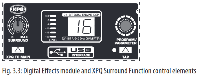
LEVEL
The LED level meter on the effects module should display a sufficiently high level. Take care to ensure that the clip LED only lights up at peak levels. If it is lit constantly, you are overloading the effects processor and this could cause unpleasant distortion. The FX SEND fader determines the level that reaches the effects module.
PROGRAM
You can select the effect preset by turning the PROGRAM control. The display flashes the number of the current preset. To recall the selected preset, press the button; the flashing stops. You can also recall the selected preset using the footswitch.
XPQ surround function
The surround function can be enabled/disabled with the XPQ TO MAIN switch. This is a built-in effect that widens the stereo width, thus making the sound more lively and transparent. Use the SURROUND control to determine the intensity of this effect.
Installation
Rack mounting
The packaging of your mixing console contains two 19″ rack mount brackets which can be installed on the side panels of the console.
Before you can attach the rack mount brackets to the mixing console, you need to remove the screws holding the left and right side panels. Use these screws to fasten the two brackets onto the console, being careful to note that each bracket fits a specific side. With the rack mount brackets installed, you can mount the mixing console in a commercially available 19″ rack. Be sure to allow for proper air flow around the unit, and do not place the mixing console close to radiators or power amps, so as to avoid overheating.
- Only use the screws holding the mixing console side panels to fasten the 19″ rack mounts.
Cable connections
You will need a large number of cables for the various connections to and from the console. The following illustrations show the wiring of these cables. Be sure to use only high-grade cables.
Audio connections
Please use commercial RCA cables to wire the 2-track inputs and outputs.
You can, of course, also connect unbalanced devices to the balanced input/ outputs. Use either mono plugs, or ensure that ring and sleeve are bridged inside the stereo plug (or pins 1 & 3 in the case of XLR connectors).
You must never use unbalanced XLR connectors (pins 1 and 3 connected) on the MIC inputs if you intend to use the phantom power supply.


Specifications
| Mono Inputs | |
| Microphone Inputs (XENYX Mic Preamp) | |
| Type | XLR, electronically balanced, discrete input circuitry |
| Mic E.I.N. (20 Hz — 20 kHz) | |
| @ 0 Ω source resistance | -134 dB / 135.7 dB A-weighted |
| @ 50 Ω source resistance | -131 dB / 133.5 dB A-weighted |
| @ 150 Ω source resistance | -129 dB / 130.5 dB A-weighted |
| Frequency response | <10 Hz — 150 kHz (-1 dB), <10 Hz — 200 kHz (-3 dB) |
| Gain range | +10 to +60 dB |
| Max. input level | +12 dBu @ +10 dB Gain |
| Impedance | approx. 2.6 k Ω balanced |
| Signal-to-noise ratio | 110 dB / 112 dB A-weighted (0 dBu In @ +22 dB Gain) |
| Distortion (THD + N) | 0.005% / 0.004% A-weighted |
| Line Input | |
| Type | ¼» TRS connector, electronically balanced |
| Impedance | approx. 20 kΩ balanced approx. 10 kΩ unbalanced |
| Gain range | -10 to +40 dB |
| Max. input level | +22 dBu @ 0 dB Gain |
| Fade-Out Attenuation (Crosstalk Attenuation) | |
| Main fader closed | 98 dB |
| Channel muted | 85 dB |
| Channel fader muted | 85 dB |
| Frequency Response | |
| Microphone input to main out | |
| <10 Hz — 90 kHz | +0 dB / -1 dB |
| <10 Hz — 160 kHz | +0 dB / -3 dB |
| Stereo Inputs | |
| Channels 5/6, 7/8 | |
| Microphone input | |
| Type | XLR microphone connector, electronically balanced |
| Impedance | approx. 2.6 k Ω balanced |
| Gain range | 0 dB to +40 dB |
| Max. input level | +2 dBu |
| Channels 9/10, 11/12 | |
| Stereo line inputs | |
| Type | 2 x ¼» TRS connector, unbalanced |
| Impedance | approx. 40 kΩ @ 0 dB Gain |
| Gain range | -20 dB to +20 dB |
| Max. input level | +22 dBu @ 0 dB Gain |
| CD/Tape In | |
| Type | RCA connectors |
| Impedance | approx. 10 kΩ |
| Max. input level | +22 dBu |
| EQ Mono Channels | |
| Low | 80 Hz / ±15 dB |
| Mid | 2.5 kHz / ±15 dB |
| High | 12 kHz / ±15 dB |
| Low cut | 80 Hz, 18 dB/oct. |
| EQ Stereo Channels | |
| Low | 80 Hz / ±15 dB |
| Mid | 2.5 kHz / ±15 dB |
| High | 12 kHz / ±15 dB |
| MON/FX Send | |
| Type | ¼» TS connector, unbalanced |
| Impedance | approx. 120 Ω |
| Max. output level | +22 dBu |
| Aux Returns | |
| Type | ¼» TRS connector, unbalanced |
| Impedance | approx. 10 k Ω |
| Max. input level | +22 dBu |
| Main Outputs | |
| Type | XLR, electronically balanced |
| Impedance | approx. 240 Ω balanced approx. 120 Ω unbalanced |
| Max. output level | +28 dBu |
| Headphone Output | |
| Type | ¼» TRS connector, unbalanced |
| Max. output level | +19 dBu / 150 Ω (+25 dBm) |
| CD/Tape Out | |
| Type | RCA connectors |
| Impedance | approx. 1 kΩ |
| Max. output level | +22 dBu |
| DSP | Texas Instruments |
| Converter | 24-bit Sigma-Delta 64/128-times oversampling |
| Sampling rate | 40 kHz |
| USB | |
| Audio | Stereo In/Out |
| Connector | Type B |
| Converter | 16-bit |
| Sample Rate | 48 kHz |
| Main Mix System Data | |
| Noise | |
| Main mix @ -∞, Channel fader -∞ |
-99 dB -101 dB A-weighted |
| Main mix @ 0 dB, Channel fader -∞ |
-84 dB -87 dB A-weighted |
| Main mix @ 0 dB, Channel fader @ 0 dB |
-80 dB -82 dB A-weighted |
| Power Supply | |
| Mains Voltage | 100 — 240 V~, 50 — 60 Hz |
| Power consumption | 40 W |
| Fuse | T 1.6 A H 250 V |
| Mains connection | Standard IEC receptacle |
| Physical | |
| Dimensions (H x W x D) | approx. 3 7/8 x 13 18/32 x 13 5/32″ approx. 97 x 345 x 334 mm |
| Weight (net) | approx. 8.38 lbs. approx. 3.80 kg |
Measuring conditions:
- 1 kHz rel. to 0 dBu; 20 Hz — 20 kHz; line input; main output; unity gain.
- 20 Hz — 20kHz; measured at main output. Channels 1 — 4 unity gain; EQ flat; all channels on main mix; channels 1/3 as far left as possible, channels 2/4 as far right as possible. Reference = +6 dBu.
BEHRINGER is constantly striving to manintain the highest professional standards. As a result of these efforts, modifications may be made from time to time to existing products without prior notice. Specifications and appearance may differ from those listed or illustrated.
Here you can download full pdf version of manual, it may contain additional safety instructions, warranty information, FCC rules, etc.
PT
RU
DE
PL
IT
NL
GR
SE
DK
FI
IMPORTANTE: Leia este documento
antes de utilizar o produto. Deseja mais
informação acerca deste produto?
Consulte o verso deste folheto.
ВНИМАНИЕ: Прочитайте этот
документ перед использованием
устройства. Дополнительную
информацию об устройстве вы
найдете на обратной стороне этого
буклета.
WICHTIG: Lesen sie dieses Dokument,
bevor Sie das Produkt verwenden.
Weitere Informationen zu diesem
Produkt finden Sie auf der Rückseite
dieser Broschüre.
WAŻNE: Przeczytaj niniejszy dokument
przed przystąpieniem do użytkowania.
Szczegółowe informacje dotyczące tego
produktu znajdziesz na odwrocie broszury.
IMPORTANTE: Prima di utilizzare
il prodotto, leggere il presente
documento. Desiderate ricevere
maggiori informazioni su questo
prodotto? Vi rimandiamo al retro del
presente libretto.
BELANGRIJK: lees dit document goed
door voordat u het product in gebruik
neemt. Wilt u meer informatie over dit
product? Kijk dan op de achterpagina
van dit boekje.
ΣΗΜΑΝΤΙΚΟ: Διαβάστε αυτό το έντυπο
πριν από τη χρήση του προϊόντος.
Θέλετε περισσότερες πληροφορίες για
αυτό το προϊόν; Ανατρέξτε στην πίσω
πλευρά του φυλλαδίου.
VIKTIGT: Läs det här informationen
innan produkten används. Önskas mer
information om produkten? Se baksidan
på den här broschyren.
VIGTIGT! Læs dette dokument, før
produktet tages i brug. Vil du have flere
oplysninger om produktet? Se bagsiden
af denne folder.
TÄRKEÄÄ: Lue tämä asiakirja ennen
tuotteen käyttöä. Haluatko lisätietoja
tuotteesta? Katso vihon takasivu.
Instruções de
funcionamento/
segurança
Инструкция по
эксплуатации
и технике
безопасности
Bedienungs-/
Sicherheits-
hinweise
Wskazówki
obsługi/
bezpieczeństwa
Istruzioni di
funzionamento /
sicurezza
Bedienings-/
veiligheids-
voorschriften
Οδηγίες
λειτουργίας/
ασφαλείας
Drifts-/säkerhets-
instruktioner
Betjenings-
og sikkerheds-
instruktioner
Käyttö- ja
turvallisuusohjeet
www.behringer.comA50-00000-00969
X1222USB
X1832USB
-
Contents
-
Table of Contents
-
Bookmarks
Quick Links
User Manual
X1222
Premium 16-Input 2/2-Bus Mixer with XENYX Mic Preamps
& Compressors, British EQs, 24-Bit Multi-FX Processor and
USB/Audio Interface
Related Manuals for Behringer XENYX X1222USB
Summary of Contents for Behringer XENYX X1222USB
- Page 1
User Manual X1222 Premium 16-Input 2/2-Bus Mixer with XENYX Mic Preamps & Compressors, British EQs, 24-Bit Multi-FX Processor and USB/Audio Interface… -
Page 2: Table Of Contents
4.2 Cable connections …………13 5. Specifications …………14 Thank you Congratulations! In purchasing the BEHRINGER XENYX you have acquired a mixer whose small size belies its incredible versatility and audio performance. The XENYX Series represents a milestone in the development of mixing console technology.
-
Page 3: Important Safety Instructions
A list of authorized resellers can dangerous voltage inside the moving the cart/apparatus be found on BEHRINGER’ s website behringer. com under enclosure — voltage that may be suffi cient to constitute a combination to avoid “Where to Buy”, or you can contact the MUSIC Group offi ce risk of shock.
-
Page 4: Limitation Of Liability
XENYX X1222USB User Manual • connection or operation of the unit in any way “Support” at behringer. com. If your country is not (3) This warranty does not detract from the seller’ s listed, please check if your problem can be dealt with…
-
Page 5: Introduction
(e.g. recorder/crossover/amplifier). may damage your hearing and/or your headphones or loudspeakers. The interface of BEHRINGER mixing consoles is optimized for these tasks, Turn the MAIN MIX faders and the PHONES control in the main section enabling you to easily keep track of the signal path.
-
Page 6: The User’s Manual
Please remember that you can only use either the microphone or the line Should your BEHRINGER dealer not be located in your vicinity, you may directly input of a channel at any one time. You can never use both simultaneously! contact one of our subsidiaries.
-
Page 7: Pan, Mute Switch And Channel Fader
XENYX X1222USB User Manual LOW CUT 2.1.3 Aux sends (MON and FX) The mono channels of the mixing consoles have a high-slope LOW CUT filter for eliminating unwanted, low-frequency signal components (80 Hz, 18 dB/octave). GAIN Use the GAIN control to adjust the input gain. This control should always be turned fully counter-clockwise whenever you connect or disconnect a signal Fig.
-
Page 8: Stereo Channels
XENYX X1222USB User Manual All stereo channel strips have a GAIN control for level setting. In those channels in which a mic input is present in the channel, the GAIN control has two scales: The PAN control determines the position of the channel signal within the stereo just like in the mono channels, there is a 0 to +40 dB scale that shows the image.
- Page 9
XENYX X1222USB User Manual MON SEND ◊ If the connected effects processor receives no input signal, the FX MUTE switch is probably pressed and/or the FX SEND control The aux send control MON SEND acts as master control for the monitor bus is too low. -
Page 10: Main Mix
The MAIN outputs carry the MAIN MIX signal and are on balanced XLR connectors Alternatively, the output signal of a second XENYX or BEHRINGER ULTRALINK with a nominal level of +4 dBu. Depending on how you wish to use your mixer PRO MX882 can also be connected.
-
Page 11: Graphic 7-Band Equalizer
XENYX X1222USB User Manual Recording: ◊ Connect microphones before you switch on the phantom power supply. Please do not connect microphones to the mixer (or the For mastering, using a stereo compressor such as the COMPOSER PRO-XL MDX2600 stagebox/wallbox) while the phantom power supply is switched on.
-
Page 12: Rear View Of X1222Usb
XENYX X1222USB User Manual FBQ FEEDBACK DETECTION PHANTOM The switch turns on the FBQ Feedback Detection System. It uses the LEDs in the The PHANTOM switch activates the phantom power supply for the XLR microphone frequency band faders to indicate the critical frequencies. On a per-need basis, inputs, which is required to operate condenser microphones.
-
Page 13: Xpq Surround Function
XENYX X1222USB User Manual FOOTSWITCH ¼» TS footswitch connector Connect a standard footswitch to the footswitch connector; use this to switch the strain relief clamp effects processor on and off. A flashing dot at the bottom of the display indicates sleeve if the effects processor is muted via the footswitch.
-
Page 14: Specifications
XENYX X1222USB User Manual 5. Specifications Balanced ¼» TRS connector strain relief clamp Mono Inputs sleeve ring Microphone Inputs (XENYX Mic Preamp) Type XLR, electronically balanced, discrete input circuitry Mic E.I.N. (20 Hz — 20 kHz) sleeve ground/shield source resistance -134 dB / 135.7 dB A-weighted…
- Page 15
1/3 as far left as possible, channels 2/4 as far right as possible. Reference = +6 dBu. Max. output level +28 dBu BEHRINGER is constantly striving to manintain the highest professional standards. As a result of these efforts, Headphone Output modifications may be made from time to time to existing products without prior notice. Specifications and Type ¼»… - Page 16
XENYX X1222USB User Manual FEDERAL COMMUNICATIONS COMMISSION COMPLIANCE INFORMATION XENYX X1222USB MUSIC Group Services US Inc. Responsible Party Name: 18912 North Creek Parkway, Address: Suite 200 Bothell, WA 98011, Phone: +1 425 672 0816 Phone/Fax No.: Fax: +1 425 673 7647 XENYX X1222USB complies with the FCC rules as mentioned in the following paragraph:… - Page 17
We Hear You…
Behringer
XENYX QX1222USB Брошюра
Популярность:
6547 просмотры
Подсчет страниц:
18 страницы
Тип файла:
Размер файла:
5.23 Mb
12-канальный микшер XENYX QX1222USB – это простое решение для сложной звукооператорской работы. Совместимый с электросетями напряжения 100 — 240 V, интуитивно понятный в использовании и надёжный в эксплуатации, этот пульт обеспечивает гибкую маршрутизацию сигнала, поэтапное наложение эффектов и оперативное компьютерное редактирование без подключения дополнительных устройств. Поэтому XENYX QX1222USB позволяет не только получить звук высокого качества, но и многократно уменьшить затраты времени, сил и средств.
Основные секции консоли
В канальной секции пульта расположено 12 канальных разъёмов – 4 монофонических и 4 пары стереофонических, 4 основных микрофонных входа и 2 дополнительных, подключенных к стереоканалам. При использовании специальных wireless-переходников к пульту можно подключить два беспроводных микрофона. Хорошее качество входящего сигнала на микрофонных разъёмах обеспечивается предусилителями, а совместимость с микрофонами различного типа возможна благодаря отключаемому источнику фантомного питания 48 V. Насыщенный и громкий звук в моноканалах достигается использованием настраиваемых компрессоров студийного качества.
Коррекция частотной диаграммы сигнала осуществляется трёхполосными «британскими» эквалайзерами, расположенными на каждом из каналов. Сигналы можно заглушать и подключать динамически, при помощи канальных кнопок mute и solo. Уровень входящих сигналов задаётся логарифмическими фейдерами.
Настройка итогового микса также возможна – для этого предусмотрен семиполосный эквалайзер и фейдеры громкости правого и левого канала. Независимо от них работают фейдеры уровня сигнала на выходах Mon, FX send, USB/2-Track. Для отслеживания статуса главных выходов в главной секции консоли имеется 11-уровневая светодиодная индикация громкости.
Внутри и снаружи
XENYX QX1222USB позволяет значительно модифицировать исходный сигнал как собственными встроенными средствами, так и путём подключения дополнительных устройств. Для редактирования звука первым методом в корпус микшера установлен эффект-процессор KLARK TEKNIK. Он позволяет изменять и сохранять настройки шестнадцати программ с использованием функции Tap, причём для удобства управления эффектами рядом с главной секцией пульта расположен LCD-дисплей. Отдельно вынесены функции детектирования обратной связи, настройки трёхмерного звучания и подавления вокала.
Внешние устройства для редактирования подключаются к разъёмам FX send, Foot SW и 2-Track. Обратно сигнал поступает по входам 2-Track и двум стереофоническим AUX returns. Наконец, редактирование любой сложности можно осуществлять на компьютере, для подключения к которому микшер имеет USB-интерфейс.
CD/TAPE INPUT
The CD/TAPE INPUT RCA connectors are provided for connecting a 2-track machine (e.g. DAT recorder) or also a CD player. They can also be used as stereo line input.
Alternatively, the output signal of a second XENYX or BEHRINGER ULTRALINK PRO MX882 can also be connected. If you connect a hi-fi amplifier with a source selection switch to the CD/TAPE INPUT, you can easily switch between additional sources (e.g. cassette recorder, MD player, sound card etc.).
Using the voice canceller function, you can process all signals being brought into your mixing console via these connectors.
CD/TAPE OUTPUT
These connectors are wired pre graphic EQ and pre XPQ surround function.
They carry the main mix signal (unbalanced), effects mix included. Connect the CD/TAPE OUTPUT to the inputs of your recording device. If you wish to use your mixer solely for recording purposes, the main outputs are also an alternative.
Main mix, main out connectors and headphone connector
MAIN MIX
Use the high-precision quality faders to control the output level of the main mix.
MAIN OUT
The MAIN outputs carry the MAIN MIX signal and are on balanced XLR connectors with a nominal level of +4 dBu. Depending on how you wish to use your mixer and which gear you own, you can connect the following equipment:
Live PA systems:
A stereo dynamics processor (optional), stereo equalizer (optional) and the stereo power amplifier for full-range loud-speakers with passive crossovers.
If you wish to use multi-way loudspeaker systems without an integrated crossover, you have to use an active crossover and several power amplifiers. Often, limiters are already built into active crossovers (e.g. BEHRINGER SUPER-X PRO CX2310 and ULTRADRIVE PRO DCX2496). Active crossovers are implemented directly before the power amplifier, and they divide the frequency range into several segments that are first amplified in the amplifiers and then passed onto the corresponding loudspeakers.
Recording:
For mastering, using a stereo compressor such as the COMPOSER PRO-XL MDX2600 can be recommended. Use it to custom-tailor the dynamic characteristics of your signal to the dynamic range of the recording equipment you are using. The signal is in this case passed on from the compressor into the recorder.
PHONES
The PHONES control adjusts the volume of the headphones connected to the PHONS/CTRL connector. If you connect active monitors or an amplifier, use this connector to adjust the output signal level.
- We would like to draw your attention to the fact that extreme volumes may damage your hearing and/or your headphones or loudspeakers. Turn the MAIN MIX faders and the PHONES control in the main section fully down before you switch on the unit. Always be careful to set the appropriate volume.
PHONS/CTRL connector
You can connect headphones to this ¼» TRS connector. The connector can also be used for feeding active monitor loudspeakers (or an amplifier) in your control room. For this purpose, the signal is taken directly before it is passed on to the main mix faders.
Level meter and level setting
POWER
The blue POWER LED indicates that the device is switched on.
+48 V
The red «+48 V» LED lights up when the phantom power supply is switched on. The phantom power supply is necessary for condenser microphones and is activated using the corresponding switch on the rear of the device.
- Connect microphones before you switch on the phantom power supply. Please do not connect microphones to the mixer (or the stagebox/wallbox) while the phantom power supply is switched on. In addition, the monitor/PA loudspeakers should be muted before you activate the phantom power supply. After switching on, wait approx. one minute to allow for system stabilization.
LEVEL METER/CLIP
The high-precision level meter accurately displays the appropriate signal level.
LEVEL SETTING:
When recording to a digital device, the recorder’s peak meter should not exceed 0 dB. This is because, unlike analog recordings, slightly excessive levels can create unpleasant digital distortion.
When recording to an analog device, the VU meters of the recording machine should reach approx. +3 dB with low-frequency signals (e.g. kick drum). Due to their inertia VU meters tend to display too low a signal level at frequencies above 1 kHz. This is why, for example, a Hi-Hat should only be driven as far as -10 dB. Snare drums should be driven to approx. 0 dB.
- The peak meters of your XENYX display the level virtually independent of frequency. A recording level of 0 dB is recommended for all signal types.
USB input/output
The XENYX mixer line has built-in USB connectivity, allowing stereo signals to be sent to and from the mixer and a computer. The audio sent from the mixer to a computer is identical to the MAIN MIX. Audio being sent to the mixer from a computer can be routed to the main mix with the 2-TR/USB TO MAIN button.
Connect the USB type B plug into the USB jack on the mixer, and the other end into a free USB port on your computer. There are no required drivers, but we recommend that PC users install the included ASIO driver. The driver can also be downloaded from behringer.com.
Graphic 7-band equalizer
The graphic stereo equalizer allows you to tailor the sound to the room acoustics.
FBQ FEEDBACK DETECTION
The switch turns on the FBQ Feedback Detection System. It uses the LEDs in the frequency band faders to indicate the critical frequencies. On a per-need basis, lower the frequency range in question somewhat in order to avoid feedback. The graphic stereo equalizer has to be turned on in order to use this function.
- Logically, at least one (ideally several) microphone channels have to be open for feedback to occur at all!
Feedback is particularly common when stage monitors («wedges») are concerned, because monitors project sound in the direction of microphones. Therefore, you can also use the FBQ Feedback Detection for monitors by placing the equalizer in the monitor bus (see MAIN MIX/MONITOR).
EQ IN
Use this switch to activate the graphic equalizer. When activated, the fader LEDs will illuminate.
MAIN MIX/MONITOR
This toggles the graphic equalizer between the main mix and the monitor mix. With the switch up (not depressed), the equalizer is active in stereo on the main mix, and inactive on the monitor mix.
When the switch is depressed the equalizer is active in mono on the monitor mix, and inactive on the main mix.
Rear view of X1222USB
FUSE HOLDER/IEC MAINS RECEPTACLE
The console is connected to the mains via the cable supplied, which meets the required safety standards. Blown fuses must only be replaced by fuses of the same type and rating. The mains connection is made via a cable with IEC mains connector. An appropriate mains cable is supplied with the equipment.
POWER
Use the POWER switch to power up the mixing console. The POWER switch should always be in the «Off» position when you are about to connect your unit to the mains.
To disconnect the unit from the mains, pull out the main cord plug. When installing the product, ensure that the plug is easily accessible. If mounting in a rack, ensure that the mains can be easily disconnected by a plug pull or by an all-pole disconnect switch on or near the rack.
Attention: The POWER switch does not fully disconnect the unit from the mains. Unplug the power cord completely when the unit is not used for prolonged periods of time.
PHANTOM
The PHANTOM switch activates the phantom power supply for the XLR microphone inputs, which is required to operate condenser microphones. The red +48 V LED lights up when phantom power is on. As a rule, dynamic microphones can still be used with phantom power switched on, provided that they are wired in a balanced configuration. In case of doubt, contact the microphone manufacturer!
- Connect microphones before you switch on the phantom power supply. Please do not connect microphones to the mixer (or the stagebox/ wallbox) while the phantom power supply is switched on. In addition, the monitor/PA loudspeakers should be muted before you activate the phantom power supply. After switching on, wait approx. one minute to allow for system stabilization.
You must never use unbalanced XLR connectors (PIN 1 and 3 connected) on the MIC input connectors if you want to use the phantom power supply.
SERIAL NUMBER
Please note the important information on the serial number.
Digital Effects Processor and XPQ Surround Function
Digital effects processor
24-BIT MULTI-EFFECTS PROCESSOR
Here you can find a list of all presets stored in the multi-effects processor. This built-in effects module produces high-grade standard effects such as reverb, chorus, flanger, delay and various combination effects. The integrated effects module has the advantage of requiring no wiring. This way, the danger of creating ground loops or uneven signal levels is eliminated at the outset, completely simplifying the handling.
These effect presets are designed to be added to dry signals. If you move the FX TO MAIN control, you mix the channel signal (dry) and the effect signal.
This also goes for mixing effects signals with the monitor mix. The main difference is that the mix ratio is adjusted using the FX TO MON control. Of course, a signal has to be fed into the effects processor via the FX control in the channel strip for both applications.
FOOTSWITCH
Connect a standard footswitch to the footswitch connector; use this to switch the effects processor on and off. A flashing dot at the bottom of the display indicates if the effects processor is muted via the footswitch
LEVEL
The LED level meter on the effects module should display a sufficiently high level. Take care to ensure that the clip LED only lights up at peak levels. If it is lit constantly, you are overloading the effects processor and this could cause unpleasant distortion. The FX SEND fader determines the level that reaches the effects module.
PROGRAM
You can select the effect preset by turning the PROGRAM control. The display flashes the number of the current preset. To recall the selected preset, press the button; the flashing stops. You can also recall the selected preset using the footswitch.
XPQ surround function
The surround function can be enabled/disabled with the XPQ TO MAIN switch. This is a built-in effect that widens the stereo width, thus making the sound more lively and transparent. Use the SURROUND control to determine the intensity of this effect.
Installation
Rack mounting
The packaging of your mixing console contains two 19″ rack mount brackets which can be installed on the side panels of the console.
Before you can attach the rack mount brackets to the mixing console, you need to remove the screws holding the left and right side panels. Use these screws to fasten the two brackets onto the console, being careful to note that each bracket fits a specific side. With the rack mount brackets installed, you can mount the mixing console in a commercially available 19″ rack. Be sure to allow for proper air flow around the unit, and do not place the mixing console close to radiators or power amps, so as to avoid overheating.
- Only use the screws holding the mixing console side panels to fasten the 19″ rack mounts.
Cable connections
You will need a large number of cables for the various connections to and from the console. The following illustrations show the wiring of these cables. Be sure to use only high-grade cables.
Audio connections
Please use commercial RCA cables to wire the 2-track inputs and outputs.
You can, of course, also connect unbalanced devices to the balanced input/ outputs. Use either mono plugs, or ensure that ring and sleeve are bridged inside the stereo plug (or pins 1 & 3 in the case of XLR connectors).
You must never use unbalanced XLR connectors (pins 1 and 3 connected) on the MIC inputs if you intend to use the phantom power supply.
Specifications
| Mono Inputs | |
| Microphone Inputs (XENYX Mic Preamp) | |
| Type | XLR, electronically balanced, discrete input circuitry |
| Mic E.I.N. (20 Hz — 20 kHz) | |
| @ 0 Ω source resistance | -134 dB / 135.7 dB A-weighted |
| @ 50 Ω source resistance | -131 dB / 133.5 dB A-weighted |
| @ 150 Ω source resistance | -129 dB / 130.5 dB A-weighted |
| Frequency response | <10 Hz — 150 kHz (-1 dB), <10 Hz — 200 kHz (-3 dB) |
| Gain range | +10 to +60 dB |
| Max. input level | +12 dBu @ +10 dB Gain |
| Impedance | approx. 2.6 k Ω balanced |
| Signal-to-noise ratio | 110 dB / 112 dB A-weighted (0 dBu In @ +22 dB Gain) |
| Distortion (THD + N) | 0.005% / 0.004% A-weighted |
| Line Input | |
| Type | ¼» TRS connector, electronically balanced |
| Impedance | approx. 20 kΩ balanced approx. 10 kΩ unbalanced |
| Gain range | -10 to +40 dB |
| Max. input level | +22 dBu @ 0 dB Gain |
| Fade-Out Attenuation (Crosstalk Attenuation) | |
| Main fader closed | 98 dB |
| Channel muted | 85 dB |
| Channel fader muted | 85 dB |
| Frequency Response | |
| Microphone input to main out | |
| <10 Hz — 90 kHz | +0 dB / -1 dB |
| <10 Hz — 160 kHz | +0 dB / -3 dB |
| Stereo Inputs | |
| Channels 5/6, 7/8 | |
| Microphone input | |
| Type | XLR microphone connector, electronically balanced |
| Impedance | approx. 2.6 k Ω balanced |
| Gain range | 0 dB to +40 dB |
| Max. input level | +2 dBu |
| Channels 9/10, 11/12 | |
| Stereo line inputs | |
| Type | 2 x ¼» TRS connector, unbalanced |
| Impedance | approx. 40 kΩ @ 0 dB Gain |
| Gain range | -20 dB to +20 dB |
| Max. input level | +22 dBu @ 0 dB Gain |
| CD/Tape In | |
| Type | RCA connectors |
| Impedance | approx. 10 kΩ |
| Max. input level | +22 dBu |
| EQ Mono Channels | |
| Low | 80 Hz / ±15 dB |
| Mid | 2.5 kHz / ±15 dB |
| High | 12 kHz / ±15 dB |
| Low cut | 80 Hz, 18 dB/oct. |
| EQ Stereo Channels | |
| Low | 80 Hz / ±15 dB |
| Mid | 2.5 kHz / ±15 dB |
| High | 12 kHz / ±15 dB |
| MON/FX Send | |
| Type | ¼» TS connector, unbalanced |
| Impedance | approx. 120 Ω |
| Max. output level | +22 dBu |
| Aux Returns | |
| Type | ¼» TRS connector, unbalanced |
| Impedance | approx. 10 k Ω |
| Max. input level | +22 dBu |
| Main Outputs | |
| Type | XLR, electronically balanced |
| Impedance | approx. 240 Ω balanced approx. 120 Ω unbalanced |
| Max. output level | +28 dBu |
| Headphone Output | |
| Type | ¼» TRS connector, unbalanced |
| Max. output level | +19 dBu / 150 Ω (+25 dBm) |
| CD/Tape Out | |
| Type | RCA connectors |
| Impedance | approx. 1 kΩ |
| Max. output level | +22 dBu |
| DSP | Texas Instruments |
| Converter | 24-bit Sigma-Delta 64/128-times oversampling |
| Sampling rate | 40 kHz |
| USB | |
| Audio | Stereo In/Out |
| Connector | Type B |
| Converter | 16-bit |
| Sample Rate | 48 kHz |
| Main Mix System Data | |
| Noise | |
| Main mix @ -∞, Channel fader -∞ |
-99 dB -101 dB A-weighted |
| Main mix @ 0 dB, Channel fader -∞ |
-84 dB -87 dB A-weighted |
| Main mix @ 0 dB, Channel fader @ 0 dB |
-80 dB -82 dB A-weighted |
| Power Supply | |
| Mains Voltage | 100 — 240 V~, 50 — 60 Hz |
| Power consumption | 40 W |
| Fuse | T 1.6 A H 250 V |
| Mains connection | Standard IEC receptacle |
| Physical | |
| Dimensions (H x W x D) | approx. 3 7/8 x 13 18/32 x 13 5/32″ approx. 97 x 345 x 334 mm |
| Weight (net) | approx. 8.38 lbs. approx. 3.80 kg |
Measuring conditions:
- 1 kHz rel. to 0 dBu; 20 Hz — 20 kHz; line input; main output; unity gain.
- 20 Hz — 20kHz; measured at main output. Channels 1 — 4 unity gain; EQ flat; all channels on main mix; channels 1/3 as far left as possible, channels 2/4 as far right as possible. Reference = +6 dBu.
BEHRINGER is constantly striving to manintain the highest professional standards. As a result of these efforts, modifications may be made from time to time to existing products without prior notice. Specifications and appearance may differ from those listed or illustrated.
Here you can download full pdf version of manual, it may contain additional safety instructions, warranty information, FCC rules, etc.
PT
RU
DE
PL
IT
NL
GR
SE
DK
FI
IMPORTANTE: Leia este documento
antes de utilizar o produto. Deseja mais
informação acerca deste produto?
Consulte o verso deste folheto.
ВНИМАНИЕ: Прочитайте этот
документ перед использованием
устройства. Дополнительную
информацию об устройстве вы
найдете на обратной стороне этого
буклета.
WICHTIG: Lesen sie dieses Dokument,
bevor Sie das Produkt verwenden.
Weitere Informationen zu diesem
Produkt finden Sie auf der Rückseite
dieser Broschüre.
WAŻNE: Przeczytaj niniejszy dokument
przed przystąpieniem do użytkowania.
Szczegółowe informacje dotyczące tego
produktu znajdziesz na odwrocie broszury.
IMPORTANTE: Prima di utilizzare
il prodotto, leggere il presente
documento. Desiderate ricevere
maggiori informazioni su questo
prodotto? Vi rimandiamo al retro del
presente libretto.
BELANGRIJK: lees dit document goed
door voordat u het product in gebruik
neemt. Wilt u meer informatie over dit
product? Kijk dan op de achterpagina
van dit boekje.
ΣΗΜΑΝΤΙΚΟ: Διαβάστε αυτό το έντυπο
πριν από τη χρήση του προϊόντος.
Θέλετε περισσότερες πληροφορίες για
αυτό το προϊόν; Ανατρέξτε στην πίσω
πλευρά του φυλλαδίου.
VIKTIGT: Läs det här informationen
innan produkten används. Önskas mer
information om produkten? Se baksidan
på den här broschyren.
VIGTIGT! Læs dette dokument, før
produktet tages i brug. Vil du have flere
oplysninger om produktet? Se bagsiden
af denne folder.
TÄRKEÄÄ: Lue tämä asiakirja ennen
tuotteen käyttöä. Haluatko lisätietoja
tuotteesta? Katso vihon takasivu.
Instruções de
funcionamento/
segurança
Инструкция по
эксплуатации
и технике
безопасности
Bedienungs-/
Sicherheits-
hinweise
Wskazówki
obsługi/
bezpieczeństwa
Istruzioni di
funzionamento /
sicurezza
Bedienings-/
veiligheids-
voorschriften
Οδηγίες
λειτουργίας/
ασφαλείας
Drifts-/säkerhets-
instruktioner
Betjenings-
og sikkerheds-
instruktioner
Käyttö- ja
turvallisuusohjeet
www.behringer.comA50-00000-00969
X1222USB
X1832USB
-
Contents
-
Table of Contents
-
Bookmarks
Quick Links
User Manual
X1222
Premium 16-Input 2/2-Bus Mixer with XENYX Mic Preamps
& Compressors, British EQs, 24-Bit Multi-FX Processor and
USB/Audio Interface
Related Manuals for Behringer XENYX X1222USB
Summary of Contents for Behringer XENYX X1222USB
- Page 1
User Manual X1222 Premium 16-Input 2/2-Bus Mixer with XENYX Mic Preamps & Compressors, British EQs, 24-Bit Multi-FX Processor and USB/Audio Interface… -
Page 2: Table Of Contents
4.2 Cable connections …………13 5. Specifications …………14 Thank you Congratulations! In purchasing the BEHRINGER XENYX you have acquired a mixer whose small size belies its incredible versatility and audio performance. The XENYX Series represents a milestone in the development of mixing console technology.
-
Page 3: Important Safety Instructions
A list of authorized resellers can dangerous voltage inside the moving the cart/apparatus be found on BEHRINGER’ s website behringer. com under enclosure — voltage that may be suffi cient to constitute a combination to avoid “Where to Buy”, or you can contact the MUSIC Group offi ce risk of shock.
-
Page 4: Limitation Of Liability
XENYX X1222USB User Manual • connection or operation of the unit in any way “Support” at behringer. com. If your country is not (3) This warranty does not detract from the seller’ s listed, please check if your problem can be dealt with…
-
Page 5: Introduction
(e.g. recorder/crossover/amplifier). may damage your hearing and/or your headphones or loudspeakers. The interface of BEHRINGER mixing consoles is optimized for these tasks, Turn the MAIN MIX faders and the PHONES control in the main section enabling you to easily keep track of the signal path.
-
Page 6: The User’s Manual
Please remember that you can only use either the microphone or the line Should your BEHRINGER dealer not be located in your vicinity, you may directly input of a channel at any one time. You can never use both simultaneously! contact one of our subsidiaries.
-
Page 7: Pan, Mute Switch And Channel Fader
XENYX X1222USB User Manual LOW CUT 2.1.3 Aux sends (MON and FX) The mono channels of the mixing consoles have a high-slope LOW CUT filter for eliminating unwanted, low-frequency signal components (80 Hz, 18 dB/octave). GAIN Use the GAIN control to adjust the input gain. This control should always be turned fully counter-clockwise whenever you connect or disconnect a signal Fig.
-
Page 8: Stereo Channels
XENYX X1222USB User Manual All stereo channel strips have a GAIN control for level setting. In those channels in which a mic input is present in the channel, the GAIN control has two scales: The PAN control determines the position of the channel signal within the stereo just like in the mono channels, there is a 0 to +40 dB scale that shows the image.
- Page 9
XENYX X1222USB User Manual MON SEND ◊ If the connected effects processor receives no input signal, the FX MUTE switch is probably pressed and/or the FX SEND control The aux send control MON SEND acts as master control for the monitor bus is too low. -
Page 10: Main Mix
The MAIN outputs carry the MAIN MIX signal and are on balanced XLR connectors Alternatively, the output signal of a second XENYX or BEHRINGER ULTRALINK with a nominal level of +4 dBu. Depending on how you wish to use your mixer PRO MX882 can also be connected.
-
Page 11: Graphic 7-Band Equalizer
XENYX X1222USB User Manual Recording: ◊ Connect microphones before you switch on the phantom power supply. Please do not connect microphones to the mixer (or the For mastering, using a stereo compressor such as the COMPOSER PRO-XL MDX2600 stagebox/wallbox) while the phantom power supply is switched on.
-
Page 12: Rear View Of X1222Usb
XENYX X1222USB User Manual FBQ FEEDBACK DETECTION PHANTOM The switch turns on the FBQ Feedback Detection System. It uses the LEDs in the The PHANTOM switch activates the phantom power supply for the XLR microphone frequency band faders to indicate the critical frequencies. On a per-need basis, inputs, which is required to operate condenser microphones.
-
Page 13: Xpq Surround Function
XENYX X1222USB User Manual FOOTSWITCH ¼» TS footswitch connector Connect a standard footswitch to the footswitch connector; use this to switch the strain relief clamp effects processor on and off. A flashing dot at the bottom of the display indicates sleeve if the effects processor is muted via the footswitch.
-
Page 14: Specifications
XENYX X1222USB User Manual 5. Specifications Balanced ¼» TRS connector strain relief clamp Mono Inputs sleeve ring Microphone Inputs (XENYX Mic Preamp) Type XLR, electronically balanced, discrete input circuitry Mic E.I.N. (20 Hz — 20 kHz) sleeve ground/shield source resistance -134 dB / 135.7 dB A-weighted…
- Page 15
1/3 as far left as possible, channels 2/4 as far right as possible. Reference = +6 dBu. Max. output level +28 dBu BEHRINGER is constantly striving to manintain the highest professional standards. As a result of these efforts, Headphone Output modifications may be made from time to time to existing products without prior notice. Specifications and Type ¼»… - Page 16
XENYX X1222USB User Manual FEDERAL COMMUNICATIONS COMMISSION COMPLIANCE INFORMATION XENYX X1222USB MUSIC Group Services US Inc. Responsible Party Name: 18912 North Creek Parkway, Address: Suite 200 Bothell, WA 98011, Phone: +1 425 672 0816 Phone/Fax No.: Fax: +1 425 673 7647 XENYX X1222USB complies with the FCC rules as mentioned in the following paragraph:… - Page 17
We Hear You…
Behringer
XENYX QX1222USB Брошюра
Популярность:
6547 просмотры
Подсчет страниц:
18 страницы
Тип файла:
Размер файла:
5.23 Mb
12-канальный микшер XENYX QX1222USB – это простое решение для сложной звукооператорской работы. Совместимый с электросетями напряжения 100 — 240 V, интуитивно понятный в использовании и надёжный в эксплуатации, этот пульт обеспечивает гибкую маршрутизацию сигнала, поэтапное наложение эффектов и оперативное компьютерное редактирование без подключения дополнительных устройств. Поэтому XENYX QX1222USB позволяет не только получить звук высокого качества, но и многократно уменьшить затраты времени, сил и средств.
Основные секции консоли
В канальной секции пульта расположено 12 канальных разъёмов – 4 монофонических и 4 пары стереофонических, 4 основных микрофонных входа и 2 дополнительных, подключенных к стереоканалам. При использовании специальных wireless-переходников к пульту можно подключить два беспроводных микрофона. Хорошее качество входящего сигнала на микрофонных разъёмах обеспечивается предусилителями, а совместимость с микрофонами различного типа возможна благодаря отключаемому источнику фантомного питания 48 V. Насыщенный и громкий звук в моноканалах достигается использованием настраиваемых компрессоров студийного качества.
Коррекция частотной диаграммы сигнала осуществляется трёхполосными «британскими» эквалайзерами, расположенными на каждом из каналов. Сигналы можно заглушать и подключать динамически, при помощи канальных кнопок mute и solo. Уровень входящих сигналов задаётся логарифмическими фейдерами.
Настройка итогового микса также возможна – для этого предусмотрен семиполосный эквалайзер и фейдеры громкости правого и левого канала. Независимо от них работают фейдеры уровня сигнала на выходах Mon, FX send, USB/2-Track. Для отслеживания статуса главных выходов в главной секции консоли имеется 11-уровневая светодиодная индикация громкости.
Внутри и снаружи
XENYX QX1222USB позволяет значительно модифицировать исходный сигнал как собственными встроенными средствами, так и путём подключения дополнительных устройств. Для редактирования звука первым методом в корпус микшера установлен эффект-процессор KLARK TEKNIK. Он позволяет изменять и сохранять настройки шестнадцати программ с использованием функции Tap, причём для удобства управления эффектами рядом с главной секцией пульта расположен LCD-дисплей. Отдельно вынесены функции детектирования обратной связи, настройки трёхмерного звучания и подавления вокала.
Внешние устройства для редактирования подключаются к разъёмам FX send, Foot SW и 2-Track. Обратно сигнал поступает по входам 2-Track и двум стереофоническим AUX returns. Наконец, редактирование любой сложности можно осуществлять на компьютере, для подключения к которому микшер имеет USB-интерфейс.
5
XENYX X1222USB User Manual
1.2 The user’s manual
The user’s manual is designed to give you both an overview of the controls, as
well as detailed information on how to use them. In order to help you understand
the links between the controls, we have arranged them in groups according to
their function.
1.3 Before you get started
1.3.1 Shipment
Your mixing console was carefully packed in the factory to guarantee safe
transport. Nevertheless, we recommend that you carefully examine the
packaging and its contents for any signs of physical damage, which may have
occurred during transit.
◊
If the unit is damaged, please do NOT return it to us, but notify your
dealer and the shipping company immediately, otherwise claims for
damage or replacement may not be granted.
1.3.2 Initial operation
Be sure that there is enough space around the unit for cooling purposes and to
avoid over-heating. Please do not place your mixing console on high-temperature
devices such as radiators or power amps. The console is connected to the mains
via the supplied power cable. The console meets the required safety standards.
Blown fuses must only be replaced by fuses of the same type and rating.
◊
Please note that all units must be properly grounded. For your own
safety, you should never remove any ground connectors from electrical
devices or power cables, or render them in operative.
◊
Please ensure that only qualified people install and operate the
mixing console. During installation and operation, the user must have
sufficient electrical contact to earth, otherwise electrostatic discharges
might affect the operation of the unit.
1.3.3 Online registration
Please do remember to register your new BEHRINGER equipment right after your
purchase by visiting behringer.com (alternatively behringer.de) and kindly read
the terms and conditions of our warranty carefully.
Should your BEHRINGER product malfunction, our goal is to have it repaired as
quickly as possible. To arrange for warranty service, please contact the retailer
from whom the equipment was purchased. Should your BEHRINGER dealer not
be located in your vicinity, you may directly contact one of our subsidiaries.
Corresponding contact information is included in the original equipment
packaging (Global Contact Information/European Contact Information).
Should your country not be listed, please contact the distributor nearest
you. A list of distributors can be found in the support area of our website
(behringer.com).
Registering your purchase and equipment with us helps us process your repair
claims quicker and more efficiently.
Thank you for your cooperation!
2. Control Elements and Connectors
This chapter describes the various control elements of your mixing console.
All controls, switches and connectors will be discussed in detail.
2.1 Mono channels
2.1.1 Microphone and line inputs
Fig. 2.1: Connectors and controls of mic/line inputs
MIC
Each mono input channel offers a balanced microphone input via the XLR
connector and also features switchable +48 V phantom power supply for
condenser microphones. The XENYX preamps provide undistorted and noise-free
gain as is typically known only from costly outboard preamps.
◊
Please mute your playback system before you activate the phantom
power supply to prevent switch-on thumps being directed to your
loud speakers. Please also note the instructions in chapter 2.5
“Rear view of X1222USB”.
LINE IN
Each mono input also features a balanced line input on a ¼» connector.
Unbalanced devices (mono jacks) can also be connected to these inputs.
◊
Please remember that you can only use either the microphone
or the line input of a channel at any one time. You can never use
both simultaneously!
INSERT
Insert points enable the processing of a signal with dynamic processors or
equalizers. They are sourced pre-fader, pre-EQ and pre-aux send. Unlike reverb
or other effects devices, whose signals are usually added to the dry signal,
dynamic processors are most effective on the complete signal. In this case,
aux send paths are a less-than-perfect solution. It is better to interrupt the
signal path and insert a dynamic processor and/or equalizer. After processing,
the signal is routed back to the console at precisely the same point it left.
However, the channel signal path is interrupted only if a plug is inserted into the
corresponding jack (stereo phone plug: tip = signal output; ring = return input).
All mono input channels are equipped with inserts.
Inserts can also be used as pre-EQ direct outputs, without interrupting the signal
path. To this end, you will need a cable fitted with mono phone plugs on the tape
machine or effects device end, and a bridged stereo phone plug on the console
side (tip and ring connected).
Смотреть руководство для Behringer Xenyx X1222USB ниже. Все руководства на ManualsCat.com могут просматриваться абсолютно бесплатно. Нажав кнопку «Выбор языка» вы можете изменить язык руководства, которое хотите просмотреть.
Страница: 1
XENYX X1222USB/X1832USB • pg 2
www.behringer.com
PT
RU
DE
XENYX X1222USB/X1832USB • pg 3
www.behringer.com
PT
RU
DE
Aviso!
Terminais marcados com o símbolo
carregam corrente elétrica de magnitude
suficiente para constituir um risco de choque elétrico.
Use apenas cabos de alto-falantes comercialmente
disponíveis de alta qualidade com pluguesTS de ¼» pré-
instalados.Todas as outras instalações e modificações
devem ser efetuadas por pessoas qualificadas.
Este símbolo, onde quer que o encontre,
alerta-o para a leitura das instruções de
manuseamento que acompanham o
equipamento. Por favor leia o manual de instruções.
Atenção
De forma a diminuir o risco de choque
eléctrico, não remover a cobertura (ou
a secção de trás). Não existem peças substituíveis por
parte do utilizador no seu interior. Para esse efeito
recorrer a um técnico qualificado.
Atenção
Para reduzir o risco de incêndios ou
choques eléctricos o aparelho não deve ser
exposto à chuva nem à humidade. Além disso, não deve
ser sujeito a salpicos, nem devem ser colocados em cima
do aparelho objectos contendo líquidos, tais como jarras.
Atenção
Estas instruções de operação devem ser
utilizadas, em exclusivo, por técnicos de
assistência qualificados. Para evitar choques eléctricos
não proceda a reparações ou intervenções, que não as
indicadas nas instruções de operação, salvo se possuir as
qualifi-cações necessárias. Para evitar choques eléctricos
não proceda a reparações ou intervenções, que não as
indicadas nas instruções de operação. Só o deverá fazer
se possuir as qualificações necessárias.
Leia estas instruções.
1.
Guarde estas instruções.
2.
Preste atenção a todos os avisos.
3.
Siga todas as instruções.
4.
Não utilize este dispositivo perto de água.
5.
Limpe apenas com um pano seco.
6.
Não obstrua as entradas de ventilação. Instale de
7.
acordo com as instruções do fabricante.
Não instale perto de quaisquer fontes de calor tais
8.
como radiadores, bocas de ar quente, fogões de sala
ou outros aparelhos (incluindo amplificadores) que
produzam calor.
Não anule o objectivo de segurança das fichas
9.
polarizadas ou do tipo de ligação à terra. Uma ficha
polarizada dispõe de duas palhetas sendo uma mais
larga do que a outra. Uma ficha do tipo ligação à terra
dispõe de duas palhetas e um terceiro dente de ligação à
terra. A palheta larga ou o terceiro dente são fornecidos
para sua segurança. Se a ficha fornecida não encaixar na
sua tomada, consulte um electricista para a substituição
da tomada obsoleta.
Proteja o cabo de alimentação de pisadelas ou
10.
apertos, especialmente nas fichas, extensões, e no
local de saída da unidade. Certifique-se de que o cabo
eléctrico está protegido.Verifique particularmente nas
fichas, nos receptáculos e no ponto em que o cabo sai
do aparelho.
O aparelho tem de estar sempre conectado à rede
11.
eléctrica com o condutor de protecção intacto.
Se utilizar uma ficha de rede principal ou uma
12.
tomada de aparelhos para desligar a unidade de
funcionamento, esta deve estar sempre acessível.
Utilize apenas ligações/acessórios especificados
13.
pelo fabricante.
Utilize apenas com
14.
o carrinho, estrutura,
tripé, suporte, ou mesa
especificados pelo
fabricante ou vendidos
com o dispositivo. Quando
utilizar um carrinho,
tenha cuidado ao mover
o conjunto carrinho/dispositivo para evitar danos
provocados pela terpidação.
Desligue este dispositivo durante as trovoadas
15.
ou quando não for utilizado durante longos períodos
de tempo.
Qualquer tipo de reparação deve ser sempre
16.
efectuado por pessoal qualificado. É necessária uma
reparação sempre que a unidade tiver sido de alguma
forma danificada, como por exemplo: no caso do cabo
de alimentação ou ficha se encontrarem danificados; na
eventualidade de líquido ter sido derramado ou objectos
terem caído para dentro do dispositivo; no caso da
unidade ter estado exposta à chuva ou à humidade; se
esta não funcionar normalmente, ou se tiver caído.
Correcta eliminação deste
17.
produto: este símbolo indica que
o produto não deve ser eliminado
juntamente com os resíduos
domésticos, segundo a Directiva
REEE (2002/96/CE) e a legislação
nacional. Este produto deverá
ser levado para um centro de recolha licenciado para a
reciclagem de resíduos de equipamentos eléctricos e
electrónicos (EEE). O tratamento incorrecto deste tipo
de resíduos pode ter um eventual impacto negativo
no ambiente e na saúde humana devido a substâncias
potencialmente perigosas que estão geralmente
associadas aos EEE. Ao mesmo tempo, a sua colaboração
para a eliminação correcta deste produto irá contribuir
para a utilização eficiente dos recursos naturais. Para
mais informação acerca dos locais onde poderá deixar
o seu equipamento usado para reciclagem, é favor
contactar os serviços municipais locais, a entidade
de gestão de resíduos ou os serviços de recolha de
resíduos domésticos.
Предупреждение
Входы и выходы, обозначенные
символом, находятся под
напряжением, которое способно привести к
поражению электрическим током. Используйте
только качественный серийный акустический
кабель с готовым ¼»TS-штекером. Другие работы по
установке или модификации оборудования должен
выполнять только квалифицированный персонал.
Этот символ указывает на важную
информацию в сопроводительной
документации, касающуюся
эксплуатации и обслуживания устройства.
Пожалуйста, ознакомьтесь с инструкцией по
эксплуатации.
Внимание
Во избежание поражения
электрическим током запрещено
снимать крышку или заднюю панель устройства.
Внутри устройства нет элементов, которые
пользователь может отремонтировать
самостоятельно. Ремонтные работы должны
выполняться только квалифицированным
персоналом.
Внимание
Во избежание возникновения пожара
или поражения электрическим током
необходимо защищать устройство от воздействия
дождя или влаги, а также от попадания внутрь
капель воды или других жидкостей. Не ставьте
на устройство заполненные жидкостью сосуды,
например, вазы.
Внимание
Все сервисные указания
предназначены исключительно для
квалифицированного персонала. Во избежание
поражения электрическим током не выполняйте
ремонтных работ, не описанных в инструкции
по эксплуатации. Ремонтные работы должны
выполняться только квалифицированными
специалистами.
Прочтите эти указания.
1.
Сохраните эти указания.
2.
Придерживайтесь этих указаний.
3.
Соблюдайте все указания по эксплуатации.
4.
Не пользуйтесь устройством в
5.
непосредственной близости от воды.
Протирайте устройство только сухой тряпкой.
6.
Не загораживайте вентиляционные отверстия.
7.
При установке устройства руководствуйтесь
указаниями фирмы-производителя.
Не устанавливайте устройство вблизи
8.
источников тепла, таких как радиаторы, плиты
PT Instruções de Segurança
Importantes RU Важные указания по
ехнике безопасности
и другие излучающие тепло приборы (в том
числе усилители).
Ни в коем случае не удаляйте
9.
предохранительное устройство с двухполюсных
или заземленных штекеров. Двухполюсный
штекер имеет два контакта различной ширины.
Заземленный штекер имеет два сетевых контакта
и дополнительный контакт заземления. Широкий
контакт или дополнительный контакт заземления
служат для Вашей безопасности. Если поставляемый
формат штекера не соответствует формату Вашей
розетки, попросите электрика заменить розетку.
Прокладывайте сетевой кабель так, чтобы
10.
на него нельзя было наступить, чтобы он не
соприкасался с острыми углами и не мог быть
поврежден. Обратите особое внимание на то, чтобы
удлинительный кабель, участки рядом с вилкой и
место крепления сетевого кабеля к устройству были
хорошо защищены.
Устройство должно быть подключено к
11.
электросети через сетевую розетку с исправным
заземлением.
Если сетевая вилка или штепсельная розетка
12.
устройства служат для отключения устройства от
сети, они должны быть легко доступными.
Используйте только рекомендованные
13.
производителем дополнительные устройства и
принадлежности.
Пользуйтесь
14.
только стойками,
штативами, тележками,
креплениями или
подставками,
рекомендованными
изготовителем или
входящими в комплект
поставки устройства. Если для перемещения
устройства используется тележка, будьте осторожны
чтобы не споткнуться и не получить травму.
Отключайте устройство от сети во время грозы
15.
или при длительных перерывах в эксплуатации.
Поручайте выполнение всех работ по ремонту
16.
устройства только квалифицированному сервисному
персоналу. Ремонт требуется при повреждении
устройства (например, при повреждении штекера
или сетевого кабеля), если внутрь устройства
попали посторонние предметы или жидкость,
если устройство находилось под дождем или во
влажной среде, если устройство упало на пол или
плохо работает.
Правильная утилизация
17.
устройства: Этот символ
указывает на то, что устройство
должно быть утилизировано
отдельно от бытовых
отходов, в соответствии
с ДирективойWEEE
(2002/96/EC) и национальным законодательством
вашего государства. Это устройство должен
быть передано на авторизованный сборочный
пункт для утилизации отходов электрического и
электронного оборудования (ЭЭО). Неправильное
обращение с такого рода отходами может оказать
негативного воздействия на окружающую среду и
здоровье человека из-за потенциально опасных
веществ, которые обычно имеются в ЭЭО. В то же
время, ваше содействие правильной утилизации
данного продукта способствует эффективному
использованию природных ресурсов. Для получения
более подробной информации о том, где можно
утилизировать вышедшее из использования
оборудование, пожалуйста, свяжитесь с местным
органами управления, уполномоченным органом по
сбору мусора или службой сбора бытовых отходов.
DE Wichtige
Sicherheitshinweise
Vorsicht
Die mit dem Symbol markierten
Anschlüsse führen so viel Spannung,
dass die Gefahr eines Stromschlags besteht.
Verwenden Sie nur hochwertige, im Handel
erhältliche Lautsprecherkabel mit vorinstallierten
6,3 mmTS-Steckern. Alle anderen Installationen
oder Modifikationen sollten nur von qualifiziertem
Fachpersonal ausgeführt werden.
Achtung
Um eine Gefährdung durch Stromschlag
auszuschließen, darf die Geräteabdeckung
bzw. Geräterückwand nicht abgenommen werden. Im
Innern des Geräts befinden sich keine vom Benutzer
reparierbarenTeile. Reparaturarbeiten dürfen nur von
qualifiziertem Personal ausgeführt werden.
Achtung
Um eine Gefährdung durch Feuer bzw.
Stromschlag auszuschließen, darf dieses
Gerät weder Regen oder Feuchtigkeit ausgesetzt werden
noch sollten Spritzwasser oder tropfende Flüssigkeiten
in das Gerät gelangen können. Stellen Sie keine mit
Flüssigkeit gefüllten Gegenstände, wie z. B.Vasen, auf
das Gerät.
Achtung
Die Service-Hinweise sind nur durch
qualifiziertes Personal zu befolgen. Um
eine Gefährdung durch Stromschlag zu vermeiden,
führen Sie bitte keinerlei Reparaturen an dem Gerät
durch, die nicht in der Bedienungsanleitung beschrieben
sind. Reparaturen sind nur von qualifiziertem
Fachpersonal durchzuführen.
Lesen Sie diese Hinweise.
1.
Bewahren Sie diese Hinweise auf.
2.
Beachten Sie alleWarnhinweise.
3.
Befolgen Sie alle Bedienungshinweise.
4.
BetreibenSiedasGerätnichtinderNähevonWasser.
5.
Reinigen Sie das Gerät mit einem trockenenTuch.
6.
Blockieren Sie nicht die Belüftungsschlitze.
7.
Beachten Sie beim Einbau des Gerätes die
Herstellerhinweise.
Stellen Sie das Gerät nicht in der Nähe von
8.
Wärmequellen auf. SolcheWärmequellen sind z. B.
Heizkörper, Herde oder andereWärme erzeugende
Geräte (auchVerstärker).
Entfernen Sie in keinem Fall die
9.
Sicherheitsvorrichtung von Zweipol- oder geerdeten
Steckern. Ein Zweipolstecker hat zwei unterschiedlich
breite Steckkontakte. Ein geerdeter Stecker hat zwei
Steckkontakte und einen dritten Erdungskontakt.
Der breitere Steckkontakt oder der zusätzliche
Erdungskontakt dient Ihrer Sicherheit. Falls das
mitgelieferte Steckerformat nicht zu Ihrer Steckdose
passt, wenden Sie sich bitte an einen Elektriker, damit
die Steckdose entsprechend ausgetauscht wird.
Verlegen Sie das Netzkabel so, dass es vorTritten
10.
und scharfen Kanten geschützt ist und nicht beschädigt
werden kann. Achten Sie bitte insbesondere im
Bereich der Stecker,Verlängerungskabel und an der
Stelle, an der das Netzkabel das Gerät verlässt, auf
ausreichenden Schutz.
Das Gerät muss jederzeit mit intaktem Schutzleiter
11.
an das Stromnetz angeschlossen sein.
Sollte der Hauptnetzstecker oder eine
12.
Gerätesteckdose die Funktionseinheit zum Abschalten
sein, muss diese immer zugänglich sein.
Verwenden Sie nur Zusatzgeräte/Zubehörteile, die
13.
laut Hersteller geeignet sind.
Verwenden
14.
Sie nurWagen,
Standvorrichtungen,
Stative, Halter oder
Tische, die vom
Hersteller benannt oder
im Lieferumfang des
Geräts enthalten sind.
Falls Sie einenWagen benutzen, seien Sie vorsichtig
beim Bewegen derWagen-Gerätkombination, um
Verletzungen durch Stolpern zu vermeiden.
Ziehen Sie den Netzstecker bei Gewitter oder wenn
15.
Sie das Gerät längere Zeit nicht benutzen.
Lassen Sie alleWartungsarbeiten nur von
16.
qualifiziertem Service-Personal ausführen. Eine
Wartung ist notwendig, wenn das Gerät in irgendeiner
Weise beschädigt wurde (z. B. Beschädigung des
Netzkabels oder Steckers), Gegenstände oder Flüssigkeit
in das Geräteinnere gelangt sind, das Gerät Regen
oder Feuchtigkeit ausgesetzt wurde, das Gerät nicht
ordnungsgemäß funktioniert oder auf den Boden
gefallen ist.
Korrekte Entsorgung
17.
dieses Produkts: Dieses Symbol
weist darauf hin, das Produkt
entsprechend derWEEE
Direktive (2002/96/EC) und der
jeweiligen nationalen Gesetze
nicht zusammen mit Ihren
Haushaltsabfällen zu entsorgen. Dieses Produkt sollte
bei einer autorisierten Sammelstelle für Recycling
elektrischer und elektronischer Geräte (EEE) abgegeben
werden.Wegen bedenklicher Substanzen, die
generell mit elektrischen und elektronischen Geräten
inVerbindung stehen, könnte eine unsachgemäße
Behandlung dieser Abfallart eine negative Auswirkung
auf Umwelt und Gesundheit haben. Gleichzeitig
gewährleistet Ihr Beitrag zur richtigen Entsorgung dieses
Produkts die effektive Nutzung natürlicher Ressourcen.
Страница: 2
XENYX X1222USB/X1832USB • pg 10
www.behringer.com
XENYX X1222USB/X1832USB • pg 11
www.behringer.com
Produtosquenãocumpremcomostermosdesta
[9]
garantialimitadaserãoconsertadossobdespesado
comprador.BEHRINGERouseucentrodeserviçoautorizado
informaráocompradordetalcircunstância.Casoo
compradorfalteemenviarumpedidodereparoporescrito
dentrode6semanasapósanotificação,BEHRINGER
devolveráaunidadecompagamentonaentregacom
umafaturaseparadaparaofreteeembalagem.Taiscustos
tambémestarãoinclusosemfaturasseparadasquandoo
compradortiverenviadoopedidodereparoporescrito.
Fornecedores autorizados BEHRINGER não vendem
[10]
produtos novos diretamente em leilões online. Compras
feitas através de leilões online estão sob os cuidados do
comprador. Confirmações e recibos de compra de leilões
online não são aceitos para verificação de garantia e a
BEHRINGER não consertará ou trocará qualquer produto
comprado através de leilões online.
Transferência de Garantia
§ 5
A presente garantia limitada é estendida exclusivamente
ao comprador original (cliente de um distribuidor
autorizado) e não é transferível a qualquer um que
possa subseqüentemente comprar este produto.
Nenhuma outra pessoa (distribuidor, etc.) deverá ser
intitulada a dar alguma promessa de garantia em nome
da BEHRINGER.
Processo de indenização
§ 6
Sujeita somente à operação de leis obrigatórias de
aplicação local, a BEHRINGER não terá qualquer
obrigação financeira ao comprador pela presente
garantia por qualquer perda consecutiva ou indireta
ou danos de qualquer espécie. De forma alguma deve
a obrigação financeira da BEHRINGER sob a presente
garantia exceder o valor total da fatura do produto.
Limitação de responsabilidade
§ 7
legal
A presente garantia limitada é a garantia completa e
exclusiva entre você e a BEHRINGER. Ela substitui todas
as outras comunicações escritas ou faladas relacionadas
a este produto. A BEHRINGER não oferece outras
garantias a este produto.
Direitos de outra garantia e
§ 8
lei nacional
Apresentegarantialimitadanãoexcluioulimita
[1]
osdireitoslegaisdocompradorcomoumconsumidorde
nenhumaforma.
Osregulamentosdagarantialimitadaaqui
[2]
mencionadossãoaplicadosaomenosqueosmesmos
constituamumainfraçãoàsleisobrigatóriasde
aplicaçãolocal.
Estagarantianãodiminuiasobrigaçõesdovendedor
[3]
noqueconcerneaqualquerfaltadeconformidadeao
produtoouqualquerdefeitoescondido.
Emenda
§ 9
As condições de serviço de garantia estão sujeitas a
mudança sem aviso prévio. Para os últimos termos
e condições e informações adicionais com respeito à
garantia limitada da BEHRINGER, favor consultar os
detalhes completos online em www.behringer.com.
* BEHRINGER Macao Commercial Offshore Limitada de Rue de
Pequim No. 202-A, Centro Financeiro de Macau 9/J, Macau, incluindo
todo o grupo BEHRINGER de companhias
Ограниченная гарантия
Гарантия
§ 1
Настоящаягарантиядействительнатолько
[1]
вслучаепокупкипродукцииBEHRINGERу
авторизированногодилеравстране,гдекуплентовар.
Списокавторизованныхдилеровможнонайтина
сайтеBEHRINGER:www.behringer.comнастранице
“Гдекупить”(WheretoBuy)илиузнатьвближайшем
офисекомпанииBEHRINGER.
КомпанияBEHRINGER*предоставляетгарантию
[2]
навсемеханическиеиэлектронныедеталиустройства
приусловиинадлежащегоиспользованиясроком
наодин(1)годсодняпокупки(см.положения§4
настоящейГарантии),еслиподействующемуместному
законодательствунепредусмотренболеедлительный
гарантийныйсрок.Есливтечениегарантийногосрока
будутобнаруженынеисправности,возникшиепо
причинам,неуказаннымв§4,компанияBEHRINGER
либозаменитустройствоновым,либоотремонтирует
егопосвоемуусмотрениюспомощьюновыхили
отремонтированныхдеталей.ЕсликомпанияBEHRINGER
решитзаменитьпродуктновым,срокгарантиина
новыйтоваростанетсябезизменений,т.е.один(1)год
(либоинойминимальныйустановленныйгарантийный
период)содняпокупкипервогоизделия.
Приобоснованныхгарантийныхтребованиях
[3]
отремонтированныйилизамененныйтоварбудет
возвращенпользователюзасчеткомпанииBEHRINGER.
Иныегарантийныеуслугинеоказываются.
[4]
ПОЖАЛУЙСТА, СОХРАНИТЕ ТОВАРНЫЙ ЧЕК. ОН
ЯВЛЯЕТСЯ ДОКАЗАТЕЛЬСТВОМ ГАРАНТИЙНОЙ
ПОКУПКИ. БЕЗ ЧЕКА ДАННАЯ ГАРАНТИЯ
НЕДЕЙСТВИТЕЛЬНА.
Регистрация онлайн
§ 2
Не забудьте зарегистрировать Ваше новое
устройство BEHRINGER на странице“Поддержка”
(Support) на сайте www.behringer.com сразу после
покупки, а также, пожалуйста, внимательно
прочтите гарантийные условия. Регистрация покупки
и прибора на нашем сайте поможет облегчить
процедуру оформления гарантийного случая.
Благодарим Вас за сотрудничество!
Номер RMA (разрешения на
§ 3
возврат)
Дляполучениягарантийногообслуживания
[1]
свяжитесьспродавцом,укоторогоВыприобрели
данноеустройство.ЕсливВашемрегионенетдилера
BEHRINGER,Выможетеобратитьсякдистрибьютору
компанииBEHRINGERпостране(см.списокстран
настранице“Поддержка”(Support))поадресу
www.behringer.com.ЕслиВашейстранынетв
списке,Выможетепопытатьсярешитьпроблемус
помощьюСлужбыподдержкиBEHRINGERнастранице
“Поддержка”(Support)поадресуwww.behringer.com.
Впротивномслучае,ПРЕЖДЕЧЕМвозвращатьтовар,
направьте,пожалуйста,своюпретензиюпогарантии
черезИнтернетпоадресуwww.behringer.com.
Всезапросыдолжнысопровождатьсяописанием
неисправностисуказаниемсерийногономератовара.
Послепроверкидействительностигарантиинатовар
наоснованиитоварногочекакомпанияBEHRINGER
присваиваетНомерразрешениянавозврат(RMA).
Послеэтогоизделиедолжнобытьотправлено
[2]
воригинальнойзаводскойупаковкесуказанием
номераразрешениянавозвратпоадресу,указанному
компаниейBEHRINGER.
Посылки,подлежащиеоплатеполучателем,
[3]
непринимаются.
Исключения по гарантии
§ 4
Настоящаягарантиянераспространяетсяна
[1]
расходныематериалы,включая,помимопрочего,
предохранителиибатареи.Всоответствующихслучаях
компанияBEHRINGERпредоставляетгарантиюна
материалирабочеесостояниелампиизмерительных
прибороввкомпоновкеустройствасрокомна
девяносто(90)днейсдатыпокупки.
Даннаягарантиянераспространяетсянаслучаи
[2]
модификацииэлектронныхилимеханических
деталейустройства.Еслитребуетсяизменение
конструкцииизделиядляобеспечениясоответствия
государственнымилилокальнымстандартам,в
любойстране,неявляющейсястраной,длякоторой
данноеизделиебылоразработаноипроизведено,это
небудетсчитатьсянеисправностьюилидефектом.
Даннаягарантиянераспространяетсянаизменения/
усовершенствованиятакогохарактера,независимо
отправильностиихосуществления.Согласно
условиямданнойгарантии,компанияBEHRINGERне
несетматериальнойответственностизаподобные
изменения/усовершенствования.
Даннаягарантияраспространяетсятолько
[3]
нааппаратноеобеспечениеустройства.Онане
распространяетсянинатехническуюподдержкув
целяхэксплуатацииаппаратногоилипрограммного
обеспечения,нинапрограммныепродукты,
независимооттого,входятлионивкомплектпоставки
устройства.Любоеподобноепрограммноеобеспечение
поставляется“КАКЕСТЬ”,еслииноенеоговариваетсяв
гарантииприлагаемогопрограммногообеспечения.
Еслизаводскойномеризделияизмененили
[4]
удален,даннаягарантиясчитаетсянедействительной.
Даннаягарантиянераспространяетсянаремонт/
[5]
обслуживаниеизделий,еслинеисправностивозникли
ввидуненадлежащегоиспользованияизделия.Это
такжеотноситсяикнеисправностям,связаннымс
обычнымизносомбыстроизнашивающихсядеталей,в
частностифейдеров,кросс-фейдеров,потенциометров,
кнопок/клавиш,ламп,гитарныхструн,осветительных
приборовииныханалогичныхкомпонентов.
Гарантиянераспространяетсянаповреждения/
[6]
дефекты,возникшиеприследующихобстоятельствах:
ненадлежащееиспользование,небрежное
•
обращениесизделиемилинесоблюдение
положенийиправилинструкцийпоэксплуатацииили
техническомуобслуживаниюпродукцииBEHRINGER;
нарушениепринятыхвстранеиспользования
•
товараправилтехникибезопасностипри
подключенииилиэксплуатации;
повреждения/дефекты,полученныеврезультате
•
действиянепреодолимойсилы(несчастный
случай,пожар,наводнениеидр.)либоподругой
причине,независящейоткомпанииBEHRINGER.
Любойнеавторизированныйремонтиливскрытие
[7]
приборапостороннимилицами,включаяпользователя,
будетозначатьотменугарантийныхобязательств.
Еслипослеобследованияизделияспециалистами
[8]
BEHRINGERокажется,чтогарантиянадефектне
распространяется,клиентобязаноплатитьуслугипо
проверкеизделия.
Изделия,накоторыегарантиянераспространяется,
[9]
ремонтируютсяисключительнозасчётпокупателя.
КомпанияBEHRINGERилиееавторизованный
сервисныйцентрпроинформируетпокупателяпри
возникновениитакихобстоятельств.Еслипокупательне
оплатитзаказвтечение6недельпослеуведомления,
компанияBEHRINGERвозвратитизделиеналоженным
платежомсотдельнымсчетомзадоставкуиупаковку.
Еслипокупательнаправилписьменныйзаказнаремонт,
такиезатратытакжевключаютсявотдельныйплатёж.
Авторизованные дилеры продукции BEHRINGER
[10]
не продают новые товары с интерактивных
аукционов. Товары на интерактивном аукционе
продаются “под ответственность покупателя”.
Товарные чеки и документы, подтверждающие
покупку на интерактивном аукционе, не
считаются обоснованием для действия гарантии,
и компания BEHRINGER не будет осуществлять
ремонт либо замену товара, приобретенного через
интерактивный аукцион.
Передача гарантии
§ 5
Данная гарантия распространяется исключительно
на первоначального покупателя (клиента
авторизованного розничного дилера) и не подлежит
передаче другим лицам, приобретающим у
такого покупателя данный товар. Другие лица
(розничные дилеры и т.д.) не могут принимать
на себя гарантийные обязательства от имени
компании BEHRINGER.
Требование о возмещении
§ 6
ущерба
КомпанияBEHRINGERненесетобязательствперед
покупателемпонастоящейгарантиивотношении
каких-либокосвенныхубытковилиущерба,если
иноенепредусмотренодействующимместным
законодательством.Влюбомслучае,размер
обязательствкомпанииBEHRINGERподаннойгарантии
неможетпревышатьфактурнуюстоимостьизделия.
Ограничение ответственности
§ 7
Положения данной гарантии являются
окончательными и распространяются исключительно
на покупателя и компанию BEHRINGER. Они
отменяют все письменные и устные договоренности,
касающиеся данного товара. Компания BEHRINGER не
предоставляет иных гарантий к данному изделию.
Другие гарантийные права и
§ 8
внутригосударственное право
Даннаягарантиянеотменяетинеограничивает
[1]
законныеправапокупателя.
Положениягарантии,содержащиесявданном
[2]
документе,действительнывтомслучае,если
онинепротиворечатдействующемуместному
законодательству.
Даннаягарантиянеотменяетобязательства
[3]
продавцавотношениинесоответствийлибоскрытых
дефектовтовара.
Внесение изменений и
§ 9
дополнений
Условия гарантийного обслуживания могут
изменяться без предварительного уведомления.
Последняя редакция гарантийных условий, а
также дополнительная информация о гарантии,
предоставляемой компанией BEHRINGER, доступна
на сайте www.behringer.com.
* BEHRINGER Macao Commercial Offshore Limited of Rue de Pequim
No. 202-A, Macau Finance Centre 9/J, Macau, включая все компании
группы BEHRINGER
Eingeschränkte Garantie
Garantie
§ 1
DieseeingeschränkteGarantieistnurgültig,wenn
[1]
SiedasProduktvoneinemautorisiertenBEHRINGER
HändlerimEinkaufslanderworbenhaben.EineListemit
autorisiertenHändlernfindenSieaufBEHRINGERsWebsite
www.behringer.comunter„WheretoBuy“oderSie
kontaktiereneineBEHRINGERNiederlassunginIhrerNähe.
BEHRINGER*garantiertfürdenZeitraumeines
[2]
(1)JahresabDatumdesErstkaufs,sofernkeine
längereMindestgarantiezeitvongeltendenörtlichen
Gesetzengefordertist,dassdiemechanischenund
elektronischenBauteiledesGerätesfreivonMaterial-und
Verarbeitungsfehlernsind,wenndasGerätunternormalen
Betriebsbedingungeneingesetztwird(sieheBedingungen
dereingeschränktenGarantiein§4unten).Wenndas
ProduktwährendderfestgelegtenGarantiezeiteinenDefekt
aufweistunddieserDefektnichtunter§4ausgeschlossen
ist,wirdBEHRINGERnachihremErmessendasProdukt
mittelsgeeigneterneueroderaufbereiteterProdukte
oderBauteileentwederersetzenoderreparieren.Sollte
BEHRINGERsichentschließen,dasProduktkomplettzu
ersetzen,wirddieseeingeschränkteGarantiefürdieDauer
derverbleibendenursprünglichenGarantiezeit,d.h.ein(1)
Jahr(odereineandereanwendbareMindestgarantiezeit)ab
DatumdesErstkaufsaufdasErsatzproduktangewandt.
BeiberechtigtenGarantieansprüchenwirddas
[3]
reparierteoderersetzteProduktfrachtfreivonBEHRINGERan
denKundenzurückgesandt.
AnderealsdievorgenanntenGarantieleistungen
[4]
werdennichtgewährt.
BITTE BEWAHREN SIE IHREN KASSENZETTEL
SORGFÄLTIG AUF. ER DIENT ALS KAUFBELEG UND
GARANTIEBERECHTIGUNG. OHNE KAUFBELEG HABEN SIE
KEINEN GARANTIEANSPRUCH.
Online Registrierung
§ 2
Registrieren Sie bitte Ihr neues BEHRINGER
Gerät möglichst direkt nach dem Kauf unter
www.behringer.com in der Rubrik“Support”und
lesen Sie aufmerksam die Bedingungen unserer
eingeschränkten Garantie. Nach der Registrierung
Ihres Kaufs und Geräts bei uns können wir Ihre
Reparaturansprüche wesentlich schneller und effizienter
bearbeiten.Viele Dank für Ihre Mitarbeit!
Reparaturnummer
§ 3
UmGarantieleistungenzuerhalten,setzenSie
[1]
sichbittemitdemHändlerinVerbindung,beidemSie
dasGerätgekaufthaben.SolltesichIhrBEHRINGER
HändlernichtinIhrerNähebefinden,könnenSieauch
denBEHRINGERVertriebIhresLandeskontaktieren,der
unterwww.behringer.cominderRubrik„Support“
aufgelistetist.WennIhrLandnichtaufgeführtist,können
SieauchdenBEHRINGERCustomerServicekontaktieren,
derebenfallsunterwww.behringer.cominderRubrik
„Support“zufindenist.AlternativreichenSiebitteIhren
Garantieanspruchonlineunterwww.behringer.comein,
BEVORSiedasProduktzurücksenden.AlleAnfragenmüssen
ergänztwerdenvoneinerBeschreibungdesProblems
undderSeriennummerdesProdukts.NachPrüfungdes
GarantieanspruchsanhanddesursprünglichenKaufbelegs
stelltBEHRINGEReineReparaturnummer(“RMA”)aus.
DasGerätmussanschließendimOriginalkarton
[2]
zusammenmitderReparaturnummerandievon
BEHRINGERgenannteAdressegeschicktwerden.
UnfreieSendungenwerdennichtangenommen.
[3]
Garantieausschluss
§ 4
DieseeingeschränkteGarantiegiltnichtfür
[1]
Verschleißteile,wieSicherungenundBatterien.Wo
anwendbar,gewährtBEHRINGERfürneunzig(90)
TageabKaufdatumdieGarantie,dassdieimProdukt
enthaltenenRöhrenoderAnzeigenfreivonMaterial-und
Verarbeitungsfehlernsind.
DieseeingeschränkteGarantiegiltnichtfürProdukte,
[2]
dieaufirgendeineWeiseelektronischodermechanisch
modifiziertwurden.WenneinProduktverändertoder
angepasstwerdenmuss,damitesineinemLand,fürdas
esursprünglichnichtentwickeltoderhergestelltwurde,
dengeltendentechnischenodersicherheitstechnischen
StandardsaufnationaleroderlokalerEbeneentspricht,
istdieseVeränderung/AnpassungnichtalsMaterial-oder
Verarbeitungsfehleranzusehen.Dieseeingeschränkte
GarantieumfasstnichtderartigeVeränderungen/
Anpassungenunabhängigdavon,obdieseordnungsgemäß
durchgeführtwurdenodernicht.BEHRINGERübernimmtim
RahmendieserGarantiefürderartigeVeränderungenauch
keineKosten.
DieseeingeschränkteGarantiegiltnurfürdie
[3]
HardwaredesProdukts.Sieschließtkeinetechnische
UnterstützungfürdieAnwendungderHard-oderSoftware
einundsiegiltnichtfürSoftware-Produkte,gleichgültig
obsieimProduktenthaltensindodernicht.DieSoftware
wirdim„IST-ZUSTAND“geliefert,sofernihrkeinebesondere
eingeschränkteSoftware-Garantiebeiliegt.
DieseeingeschränkteGarantieerlischt,wenndie
[4]
imWerkangebrachteSeriennummerverändertoder
entferntwurde.
DieseeingeschränkteGarantieberechtigtnicht
[5]
zurkostenlosenInspektionundWartung/Reparaturdes
Geräts,insbesonderewenndieDefekteaufunsachgemäße
Benutzungzurückzuführensind.DieGarantiegiltauch
nichtfürDefektedurchnormaleAbnutzung,besonders
beiFadern,Crossfadern,Potentiometern,Tasten,Röhren,
Gitarrensaiten,LeuchtmittelnundähnlichenTeilen.
UnterdieseeingeschränkteGarantiefallenauchkeine
[6]
Schäden/Defekte,dieverursachtwurdendurch:
unsachgemäßeHandhabung,Nachlässigkeitoder
•
FehlgebrauchdesGerätesentgegendenHinweisen,
dieindenBedienungs-oderWartungsanleitungender
FirmeBEHRINGERaufgeführtsind;
denAnschlussoderGebrauchdesProduktsin
•
einerWeise,diedengeltendentechnischenoder
sicherheitstechnischenAnforderungenindemLand,in
demdasGeräteingesetztwird,nichtentspricht;
Страница: 3
XENYX X1222USB/X1832USB • pg 42
www.behringer.com www.behringer.com
PT
RU
DE
PL
IT
NL
GR
SE
DK
FI
XENYX X1222USB/X1832USB • pg 43
XENYX X1222USB/X1832USB
TechnischeDaten
ТехническиеДанные
Monoeingänge X1222USB X1832USB
Mikrofoneingänge(XENYX
Mikrofon-Vorverstärker)
6 6
Typ
XLR-Anschluss,
elektronisch symmetrierte,
diskreteEingangsschaltung
XLR-Anschluss,
elektronisch symmetrierte,
diskrete Eingangsschaltung
MicE.I.N.1(20Hz-20kHz)
bei0ΩQuellwiderstand
-134 dB 135,7 dB
A-gewichtet
-134 dB 135,7 dB
A-gewichtet
bei50ΩQuellwiderstand
-131 dB 133,3 dB
A-gewichtet
-131 dB 133,3 dB
A-gewichtet
bei150ΩQuellwiderstand
-129 dB 130,5 dB
A-gewichtet
-129 dB 130,5 dB
A-gewichtet
Frequenzgang(–1dB) <10 Hz — 150 kHz (-1 dB) <10 Hz — 150 kHz (-1 dB)
Frequenzgang(–3dB) <10 Hz — 200 kHz (-3 dB) <10 Hz — 200 kHz (-3 dB)
Verstärkungsbereich +10 dB bis +60 dB +10 dB bis +60 dB
Max.Eingangspegel
+12 dBu bei +10 dB
Verstärkung
+12 dBu bei +10 dB
Verstärkung
Impedanz 2,6 kΩ symmetrisch 2,6 kΩ symmetrisch
Rauschabstand
110 dB A-gewichtet
(0 dBu In bei +22 dB
Verstärkung)
110 dB A-gewichtet
(0 dBu In bei +22 dB
Verstärkung)
Verzerrungen(THD+N)
0,005 % / 0,004 %
A-gewichtet
0,005 % / 0,004 %
A-gewichtet
Phantomleistung Zuschaltbar, +48 V Zuschaltbar, +48 V
Line-Eingang
Typ
6,3-mm-Stereoklinke,
elektronisch symmetriert
6,3-mm-Stereoklinke,
elektronisch symmetriert
Impedanz
20 kΩ symmetrisch,
10 kΩ unsymmetrisch
20 kΩ symmetrisch,
10 kΩ unsymmetrisch
Verstärkungsbereich -10 dB bis +40 dB -10 dB bis +40 dB
Max.Eingangspegel 30 dBu 30 dBu
Frequenzgang
(MikrofoneingangzuMainOut)
<10Hz-90kHz +0 dB / -1 dB +0 dB / -1 dB
<10Hz-160kHz +0 dB / -3 dB +0 dB / -3 dB
Stereoeingänge
Typ
4 x 6,3-mm-Stereoklinke,
zweifach symmetrisch
4 x 6,3-mm-Stereoklinke,
zweifach symmetrisch
Impedanz
20 kΩ symmetrisch,
10 kΩ unsymmetrisch
20 kΩ symmetrisch,
10 kΩ unsymmetrisch
Verstärkungsbereich -20 dB bis +20 dB -20 dB bis +20 dB
Max.Eingangspegel +22 dBu +22 dBu
2-TRACK/USB-Eingang
Typ RCA-Anschluss RCA-Anschluss
Impedanz 10 kΩ 10 kΩ
Max.Eingangspegel +22 dBu +22 dBu
Equalizer3-Band
Equalizer 3-Band
semi-parametrisch
LOW 80 Hz / ±15 dB 80 Hz / ±15 dB
MID 2,5 kHz / ±15 dB
Variabel: 100 Hz — 8 kHz /
± 15 dB
HIGH 12 kHz / ±15 dB 12 kHz / ±15 dB
Equalizer4-Bandfest
LOW – 80 Hz / ±15 dB
LOWMID – 500 Hz / ±15 dB
HIGHMID – 3 kHz / ±15 dB
HIGH – 12 kHz / ±15 dB
Kanal-Einschleifpunkte
Typ
4 x 6,3-mm-Stereoklinke,
unsymmetrisch
6 x 6,3-mm-Stereoklinke,
unsymmetrisch
Max.Eingangspegel +22 dBu +22 dBu
Моносигнал X1222USB X1832USB
Микрофонныйввод(микрофонный
предусилительXENYX)
6 6
Тип
Разъем XLR, электронно-
симметричный, дискретный
входной сигнал
Разъем XLR, электронно-
симметричный, дискретный
входной сигнал
МикрофонE.I.N.1(20Гц-20кГц)
присопротивленииисточника
0Ω
эквив.уровеньшума
-134дБ135,7дБ,A-weighted
эквив.уровеньшума
-134дБ135,7дБ,A-weighted
присопротивленииисточника
50Ω
эквив.уровеньшума
-131дБ133,3дБ,A-weighted
эквив.уровеньшума
-131дБ133,3дБ,A-weighted
присопротивленииисточника
150Ω
эквив.уровеньшума
-129дБ130,5дБ,A-weighted
эквив.уровеньшума
-129дБ130,5дБ,A-weighted
Частотнаяхарактеристика
(–1дБ)
<10 Гц — 150 кГц (-1 дБ) <10 Гц — 150 кГц (-1 дБ)
Частотнаяхарактеристика
(–3дБ)
<10 Гц — 200 кГц (-3 дБ) <10 Гц — 200 кГц (-3 дБ)
Диапазонусиления от +10 дБ до +60 дБ от +10 дБ до +60 дБ
Макс.входнойуровень
+12 dBu при усилении
+10 дБ
+12 dBu при усилении
+10 дБ
Сопротивление 2,6 кОм, симметричное 2,6 кОм, симметричное
Соотношениеуровнейсигнал-
шум
эквив. уровень шума
110 дБ, A-weighted
(0 dBu на входе при
усилении +22 дБ)
эквив. уровень шума
110 дБ, A-weighted
(0 dBu на входе при
усилении +22 дБ)
Искажение(THD+N)
эквив.уровеньшума
0,005%/0,004%,A-weighted
эквив.уровеньшума
0,005%/0,004%,A-weighted
Фантомноепитание Переключаемое, +48 В Переключаемое, +48 В
Линейныйвход
Тип
¼» TRS, электронно-
симметричный
¼» TRS, электронно-
симметричный
Сопротивление
20 кОм, симметричное;
10 кОм, несимметричное
20 кОм, симметричное;
10 кОм, несимметричное
Диапазонусиления от -10 дБ до +40 дБ от -10 дБ до +40 дБ
Макс.входнойуровень 30 dBu 30 dBu
Частотнаяхарактеристика
(микрофонныйвход-основнойвыход)
<10Гц-90кГц +0 дБ / -1 дБ +0 дБ / -1 дБ
<10Гц-160кГц +0 дБ / -3 дБ +0 дБ / -3 дБ
Стереосигнал
Тип
4 двойных ¼» TRS,
симметричные
4 двойных ¼» TRS,
симметричные
Сопротивление
20 кОм, симметричное;
10 кОм, несимметричное
20 кОм, симметричное;
10 кОм, несимметричное
Диапазонусиления от -20 дБ до +20 дБ от -20 дБ до +20 дБ
Макс.входнойуровень +22 dBu +22 dBu
Входдвухканальный/USB
Тип разъем RCA разъем RCA
Сопротивление 10 кОм 10 кОм
Макс.входнойуровень +22 dBu +22 dBu
Трехполосныйэквалайзер
Трехполосныйэквалайзер
полупараметрический
НИЗКИЕ 80 Гц / +- 15 дБ 80 Гц / +- 15 дБ
СРЕДНИЕ 2,5 кГц / +- 15 дБ
Переменная 100 Гц — 8 кГц
/ +- 15 дБ
ВЫСОКИЕ 12 кГц / +- 15 дБ 12 кГц / +- 15 дБ
Фиксированный
четырехполосныйэквалайзер
НИЗКИЕ — 80 Гц / +- 15 дБ
НИЗКИЕСРЕДНИЕ — 500 Гц / +- 15 дБ
ВЫСОКИЕСРЕДНИЕ — 3 кГц / +- 15 дБ
ВЫСОКИЕ — 12 кГц / +- 15 дБ
Гнездаканалов
Тип 4 x ¼»TRS, несимметричные 6 x ¼»TRS, несимметричные
Макс.входнойуровень +22 dBu +22 dBu
AUXSends
Typ
2 x 6,3-mm-Monoklinke,
unsymmetrisch
3 x 6,3-mm-Monoklinke,
unsymmetrisch
Impedanz 120 Ω 120 Ω
Max.Ausgangspegel +22 dBu +22 dBu
AUXReturns
Typ
2 x 6,3-mm Stereoklinke,
zweifach, symmetrisch
2 x 6,3-mm Stereoklinke,
zweifach, symmetrisch
Impedanz
20 kΩ symmetrisch
10 kΩ unsymmetrisch
20 kΩ symmetrisch,
10 kΩ unsymmetrisch
Max.Eingangspegel +22 dBu +22 dBu
Main-Ausgänge
Typ
XLR, elektronisch
symmetriert
XLR, 6,3-mm, elektronisch
symmetriert
Impedanz
240 Ω symmetrisch,
120 Ω unsymmetrisch
240 Ω symmetrisch,
120 Ω unsymmetrisch
Max.Ausgangspegel +28 dBu +28 dBu
Regieraum-Ausgang
Typ
6,3-mm-Klinke,
unsymmetrisch
6,3-mm-Klinke,
unsymmetrisch
Impedanz 120 Ω 120 Ω
Max.Ausgangspegel +22 dBu +22 dBu
Kopfhörerausgang
Typ
6,3-mm-Stereoklinke,
unsymmetrisch
6,3-mm-Stereoklinke,
unsymmetrisch
Max.Ausgangspegel
+19 dBu / 150 Ω
(+25 dBm)
+19 dBu / 150 Ω
(+25 dBm)
2-TRACK/USB-Ausgang
Typ RCA-Anschluss RCA-Anschluss
Impedanz 1 kΩ 1 kΩ
Max.Ausgangspegel +22 dBu +22 dBu
DSP
Wandler
24-Bit Delta-Sigma 24-Bit Delta-Sigma
64/128-faches
Oversampling
64/128-faches
Oversampling
Abtastrate 40 kHz 40 kHz
MainMix-Systemdaten(Rauschen)
MainMixbei-∞,Kanal-Faderbei-∞
-105 dB / -108 dB
A-gewichtet
-105 dB / -108 dB
A-gewichtet
MainMixbei0dB,Kanal-Faderbei-∞ -95 dB / -97 dB A-gewichtet -95 dB / -97 dB A-gewichtet
MainMixbei0dB,Kanal-Faderbei0dB
-82,5 dB / -85 dB
A-gewichtet
-82,5 dB / -85 dB
A-gewichtet
Stromversorgung
Netzspannung 100 — 240 V~, 50/60 Hz 100 — 240 V~, 50/60 Hz
Leistungsaufnahme 40 W 50 W
Sicherung(100–120V~,50/60Hz) T 1,6 A H 250 V T 1,6 A H 250 V
Sicherung(220-230V~,50/60Hz) T 1,6 A H 250 V T 1,6 A H 250 V
Netzstecker
Standard-
Kaltgeräteanschluss
Standard-
Kaltgeräteanschluss
USB
Audio Stereo In/Out Stereo In/Out
Anschluss Typ B Typ B
Wandler 16-Bit 16-Bit
Abtastrate 48 kHz 48 kHz
Abmessungen/Gewicht
Maße(HxBxT)
90 mm x 370 mm x
330 mm (3,54″ x 14,57″
x 13″)
90 mm x 430 mm x
355 mm (3,54″ x 16,93″
x 14″)
Gewicht 8,16 lbs / 3,7 kg 10,22 lbs / 4,64 kg
КаналыAUXSend
Тип
2 x ¼» монофонических
разъема, несимметричные
3 x ¼» монофонических
разъема, несимметричные
Сопротивление 120 Ом 120 Ом
Макс.выходнойуровень +22 dBu +22 dBu
КаналыAUXReturn
Тип
2 двойных ¼» TRS,
симметричные
2 двойных ¼» TRS,
симметричные
Сопротивление
20 кОм, симметричное
10 кОм, несимметричное
20 кОм, симметричное;
10 кОм, несимметричное
Макс.входнойуровень +22 dBu +22 dBu
Основныевыводы
Тип
XLR, электронно-
симметричный
XLR, ¼», электронно-
симметричный
Сопротивление
240 Ом, симметричное;
120 Ом, симметричное
240 Ом, симметричное;
120 Ом, симметричное
Макс.выходнойуровень +28 dBu +28 dBu
Выводвкомнату
звукорежиссера
Тип ¼» TS, несимметричный ¼» TS, несимметричный
Сопротивление 120 Ом 120 Ом
Макс.выходнойуровень +22 dBu +22 dBu
Выводдлянаушников
Тип ¼» TRS, несимметричный ¼» TRS, несимметричный
Макс.выходнойуровень
+19 dBu / 150 Ом
(+25 дБм)
+19 dBu / 150 Ом
(+25 дБм)
Выходдвухканальный/USB
Тип разъем RCA разъем RCA
Сопротивление 1 кОм 1 кОм
Макс.выходнойуровень +22 dBu +22 dBu
DSP
Преобразователь
24-битный, Delta-Sigma 24-битный, Delta-Sigma
Избыточная
дискретизация
в 64/128 раз
Избыточная
дискретизация
в 64/128 раз
Скоростьдискретизации 40 кГц 40 кГц
Системныеданныеобщего
микса(шум)
Общиймикспри-∞,
микшерканалапри-∞
эквив. уровень шума
-105 дБ / 108 дБ,
A-weighted
эквив. уровень шума
-105 дБ / 108 дБ,
A-weighted
Общиймикспри0дБ,
микшерканалапри-∞
эквив. уровень шума
-95 дБ / 97 дБ, A-weighted
эквив. уровень шума
-95 дБ / 97 дБ, A-weighted
Общиймикспри0дБ,микшер
каналапри0дБ
эквив. уровень шума
-82,5 дБ / 85 дБ,
A-weighted
эквив. уровень шума
-82,5 дБ / 85 дБ,
A-weighted
Питание
Напряжениепитания 100 — 240 В~, 50/60 Гц 100 — 240 В~, 50/60 Гц
Потреблениепитания 40 Вт 50 Вт
Предохранитель(100-230В~,50/60Гц) T 1,6 А H 250 В T 1,6 А H 250 В
Предохранитель(220-230В~,50/60Гц) T 1,6 А H 250 В T 1,6 А H 250 В
Разъемпитания Розетка стандарта IEC Розетка стандарта IEC
USB
Аудио Стереовход/Выход Стереовход/Выход
Разъем Тип B Тип B
Преобразователь 16-битный 16-битный
Скоростьдискретизации 48 кГц 48 кГц
Габариты/вес
Размеры(ВxШxГ)
90 мм x 370 мм x 330 мм
(3,54″ x 14,57″ x 13″)
90 мм x 430 мм x 355 мм
(3,54″ x 16,93″ x 14″)
Вес 3,7 кг 4,64 кг