В представленном списке руководства для конкретной модели Лобзика — Bosch PST 850 PE. Вы можете скачать инструкции к себе на компьютер или просмотреть онлайн на страницах сайта бесплатно или распечатать.
В случае если инструкция на русском не полная или нужна дополнительная информация по этому устройству, если вам нужны
дополнительные файлы: драйвера, дополнительное руководство пользователя (производители зачастую для каждого
продукта делают несколько различных документов технической помощи и руководств), свежая версия прошивки, то
вы можете задать вопрос администраторам или всем пользователям сайта, все постараются оперативно отреагировать
на ваш запрос и как можно быстрее помочь. Ваше устройство имеет характеристики:Потребляемая мощность: 620 Вт, Частота движения пилки: 500 — 3100 ходов/мин, Длина хода: 25 мм, Глубина пропила дерева: 85 мм, Глубина пропила стали: 8 мм, Маятниковый ход: есть, 4 ступени, полные характеристики смотрите в следующей вкладке.
Для многих товаров, для работы с Bosch PST 850 PE могут понадобиться различные дополнительные файлы: драйвера, патчи, обновления, программы установки. Вы можете скачать онлайн эти файлы для конкретнй модели Bosch PST 850 PE или добавить свои для бесплатного скачивания другим посетителями.
Если вы не нашли файлов и документов для этой модели то можете посмотреть интсрукции для похожих товаров и моделей, так как они зачастую отличаются небольшим изменениями и взаимодополняемы.
Обязательно напишите несколько слов о преобретенном вами товаре, чтобы каждый мог ознакомиться с вашим отзывом или вопросом. Проявляйте активность что как можно бльше людей смогли узнать мнение настоящих людей которые уже пользовались Bosch PST 850 PE.

Александр
2018-01-05 11:36:13
Отличный лобзик
Сергей
2018-03-12 23:42:56
Класс!
Отличный!!
Михаил
2019-12-08 11:32:15
Хороший лобзик, справляется со своей задачей на ура!
Михаил
2019-12-08 11:34:38
Хороший лобзик, справляется со своей задачей на ура
Афанасий
2020-08-16 05:22:16
Достался по наследству. Только знакомлюсь
Основные и самые важные характеристики модели собраны из надежных источников и по характеристикам можно найти похожие модели.
| Производительность | |
| Потребляемая мощность | 620 Вт |
| Частота движения пилки | 500 — 3100 ходов/мин |
| Длина хода | 25 мм |
| Глубина пропила дерева | 85 мм |
| Глубина пропила стали | 8 мм |
| Режимы работы | |
| Маятниковый ход | есть, 4 ступени |
| Регулировка частоты хода | есть |
| Плавный пуск | есть |
| Конструкция | |
| Рукоятка | скобовидная, обрезиненная |
| Быстрозажимное крепление пилки | есть |
| Очистка места реза | сдув опилок, подключение пылесоса |
| Подошва | литая |
| Наклон подошвы | есть, 45? |
| Антивибрационная система | есть |
| Питание | |
| Работа от аккумулятора | нет |
| Дополнительно | |
| Футляр/кейс | есть в базовой комплектации |
| Защитный щиток | есть |
| Комплектация | три пилки, противоскольный вкладыш, накладка на опорную плиту |
| Вес | 2.4 кг |
Здесь представлен список самых частых и распространенных поломок и неисправностей у Лобзиков. Если у вас такая поломка то вам повезло, это типовая неисправность для Bosch PST 850 PE и вы можете задать вопрос о том как ее устранить и вам быстро ответят или же прочитайте в вопросах и ответах ниже.
| Название поломки | Описание поломки | Действие |
|---|---|---|
| Откручиваются Винты Крепления Пилок | ||
| Поломка Опорного Ролика | ||
| Поломка Узла Фиксации Полотна | ||
| Повреждение Деталей Редуктора | ||
| Излом Или Изгиб Опорного Штока | ||
| Облом Зубьев На Цанге Лобзика | ||
| Преждевременный Износ Червячной Передачи Якоря | ||
| Болтается,Шток,Для,Пилки | ||
| Не Включаеться | Хотел Расспелить Доску Нажал Кнопку Пуска Проработал 2 Сек. И Замолчал, Ни Какого Запаха Горелого Не Почувствовал .Попробовал Еще Несколько Раз Бесполезно, Разабрал Визуальным Осмотром Ни Чего Не Обнаружил Все Провода И Двегатель В Норме. Щетки Хорошие. Р | |
| Пилки Не Входят В Держатель | Пилки Других Производителей (Кроме Тех Что Идут В Комплекте) Не Входят В Держатель По Толщине!!! | |
| Нет Регулировки Оборотов | ||
| Laser Einhell Bpsl 750 | Не Функционирует Laser | |
| Выключатель Работает Наоборот | При Нажатии Клавиши Аппарат Выключается И Наоборот | |
| Двигатель Вращается А Пилка Стоит На Месте |
В нашей базе сейчас зарегестрированно 18 353 сервиса в 513 города России, Беларусии, Казахстана и Украины.

ABSOLUTSERVIS
⭐
⭐
⭐
⭐
⭐
Адресс:
Новослободская 48.
Телефон:
79689573019
Сайт:
n/a
Время работы
Время работы не указано
ОЛИМП
⭐
⭐
⭐
⭐
⭐
Адресс:
Краснобоготырская д.2
Телефон:
74993902898
Сайт:
n/a
Время работы
Будни: с 1000 до 1900
Суббота: с 1000 до 1700
Воскресенье: выходной
ЧЕРТАНОВО-БЫТ
⭐
⭐
⭐
⭐
⭐
Адресс:
ул. Академика Янгеля д.14 к.5 стр.2
Телефон:
74956422423
Сайт:
n/a
Время работы
Будни: с 1000 до 1900
Суббота: с 1000 до 1400
Воскресенье: выходной
БАРКАС
⭐
⭐
⭐
⭐
⭐
Адресс:
вешки дом 24
Телефон:
Сайт:
n/a
Время работы
Время работы не указано
ЛУЧШИЙ ДВИГАТЕЛЬ
⭐
⭐
⭐
⭐
⭐
Адресс:
Строительный проезд д.7ак30
Телефон:
74959989788
Сайт:
n/a
Время работы
Будни: с 1000 до 1800
Суббота: с 1000 до 1500
Воскресенье: выходной

Bedienungsanleitung
Operating instructions
Instructions d’emploi
Instrucciones de servicio
Manual de instruções
Istruzioni d’uso
Gebruiksaanwijzing
Betjeningsvejledning
Bruksanvisning
Brukerveiledningen
Käyttöohje
Οδηγία χειρισµού
Kullan∂m k∂lavuzu
Deutsch
English
Français
Español
Português
Italiano
Nederlands
Dansk
Svenska
Norsk
Suomi
Eλληvικά
Türkçe
PST 650 PE
PST 750 PE
PST 850 PE
3
2
1
4
13
1
5
7
9
12
10
11
PST 850 PE
B
A
14
9
15
C
PST 650 PE
PST 750 PE
D
PST 850 PE
16
17
5
18
E
PST 650 PE
PST 750 PE
21
F
17
20
19
22
G
H
22
[W]
[W]
[min-1]
[mm]
PST 650 PE
0 603 381 7..
470
280
500–3100
23
●
●
PST 750 PE
0 603 382 7..
600
360
500–3100
23
●
●
PST 850 PE
0 603 383 7..
620
370
500–3100
23
●
●
68
15
4
0–45
1,9
/ II
75
18
6
0–45
2,4
/ II
85
18
8
0–45
2,4
/ II
2 609 932 299 • (03.03) T
■
■
■
■
■
■
■
■
■
■
■
■
■
■
■
■
■
A
2 609 932 299 • (03.03) T
■
■
Staub-/Späneabsaugung
■
■
2 609 932 299 • (03.03) T
C
D
Tipps
B
2 609 932 299 • (03.03) T
Konformitätserklärung
2 609 932 299 • (03.03) T
Dr. Eckerhard Strötgen
Head of Product
Certification
Product Specifications
Jigsaw
Order number
Rated input power
[W]
Output power
[W]
Stroke rate at no load
[per min]
Stroke
[mm]
Stroke rate selection
Pendelum action
Maximum cutting depth
in wood
[mm]
in aluminium
[mm]
in non-alloyed steel
[mm]
Bevel cuts (left/right)
[°]
Weight without mains cable approx.
[kg]
Protection class
PST 650 PE
0 603 381 7..
470
280
500–3100
23
●
●
PST 750 PE
0 603 382 7..
600
360
500–3100
23
●
●
PST 850 PE
0 603 383 7..
620
370
500–3100
23
●
●
68
15
4
0–45
1.9
/ II
75
18
6
0–45
2.4
/ II
85
18
8
0–45
2.4
/ II
Please observe the order number of your machine. The trade names of the individual machines may vary.
Noise/Vibration Information
Measured values determined according to EN 50 144.
The A-weighted sound pressure levels of the machines are typically:
PST 650 PE
82 dB(A)
PST 750 PE/PST 850 PE
84 dB(A)
The noise level when working can exceed 85 dB(A).
Wear ear protection!
PST 650 PE: The typically weighted acceleration is
5 m/s2.
PST 750 PE/PST 850 PE: The typical hand-arm vibration is below 2.5 m/s2.
Intended Use
The machine is intended for making separating cuts
and cutouts in wood, plastic, metal, ceramic plates
and rubber while resting firmly on the workpiece. It is
suitable for straight and curved cuts with bevel angles
to 45°. The saw blade recommendations are to be observed.
1 Stroke rate selection thumbwheel
2
3
4
5
6
7
8
9
10
11
12
13
14
15
16
17
18
19
20
21
22
On/off switch
Locking button for on/off switch
Blow-out opening/Vacuum hose*
Clamping lever for base plate (PST 850 PE)
Base plate
Lever for pendulum stroke adjustment
Switch for sawdust blowing device
(PST 750 PE/PST 850 PE)
SDS lever for saw blade release
Guide roller
Saw blade*
Contact protector
Dust cover for vacuuming
Stroke rod
Splintering protector*
Cutting angle scale
Screw
Protractor**
Threaded hole
Front cut-out
Retainer
Parallel Guide/Circle Cutter*
* Optional accessories
** Commercially available (not included in the delivered
items)
Not all the accessories illustrated or described are included in standard delivery.
2 609 932 299 • (03.03) T
English–1
For Your Safety
■
■
■
■
■
■
■
■
■
■
■
■
■
■
■
■
■
A
Working safely with this machine is
possible only when the operating
and safety information are read
completely and the instructions
contained therein are strictly followed.
In addition, the general safety
notes in the enclosed booklet must
be observed.
Before using for the first time, ask
for a practical demonstration.
If the cable is damaged or cut through while working, do not touch the cable but immediately pull the
mains plug. Never use the machine with a damaged cable.
Connect machines that are used in the open via a
residual current device (RCD) with an actuating
current of 30 mA maximum. Do not operate the
machine in rain or moisture.
Wear safety glasses.
Working with material containing asbestos is not
permitted.
Always direct the cable to the rear away from the
machine.
Secure the workpiece. A workpiece clamped
with clamping devices or in a vice is held more secure than by hand.
Apply the machine to the workpiece only when
switched on.
When working, never place a hand or fingers in
front of the saw blade.
The cutting path must be free of obstacles both
above and below.
When sawing, the complete surface of the base
plate 6 must be in secure contact.
For the working of smaller or thin workpieces, use
a stable foundation or a saw table (accessory).
Use only sharp, flawless saw blades. Replace immediately cracked, bent or dull saw blades.
When the cut is completed, switch off the machine
and then pull the saw blade out of the cut only after
it has come to a standstill (danger of kick-back).
Always switch the machine off and wait until it has
come to a standstill before placing it down.
After switching off, do not brake the saw blade to a
stop by applying side pressure.
Never allow children to use the machine.
Bosch is able to ensure flawless functioning of the
machine only if the original accessories intended
for it are used.
2 609 932 299 • (03.03) T
■
■
Inserting/
Changing the Saw Blade
Before any work on the machine itself, pull the
mains plug.
For inserting or changing the saw blade 11, the
wearing of protective gloves is recommended.
Inserting the Saw Blade
Insert the saw blade (teeth in the cutting direction) into
the stroke rod 14 until it latches. The SDS clamping
lever 9 springs to the rear and locks the saw blade.
Take care when inserting the saw blade that the rear
edge of the saw blade rests in the groove of the guide
roller 10.
Ejecting the Saw Blade
To eject the saw blade, turn the SDS lever 9 to the
front in the insertion position. The saw blade is released and ejected.
Dust/Chip Vacuuming
■
■
Dust produced while working can be detrimental to
health, inflammable or explosive. Suitable protection measures are required.
Examples: Some dusts are considered to be carcinogenic. Use suitable dust/chip extraction and
wear a dust protection mask.
Light metal dust can burn or explode. Always keep
the work place clean since material mixtures are
especially dangerous.
Cover Guard
When using a vacuum cleaner, always mount the dust
cover 13 and slide it completely downward.
Attaching: Insert the cover guard from above into
the guide and slide downward until it
latches.
Removing: Take hold of the cover guard on the sides
and pull off in the upward direction.
Connection for a Vacuum Cleaner
(Accessory pages)
Connect the vacuuming hose (19 mm dia., accessory)
directly to the blow-out opening 4.
The vacuum cleaner must be suitable for the material
to be worked.
When vacuuming dry dust that is especially detrimental to health or carcinogenic, use a special vacuum
cleaner.
English–2
Putting into Operation
Ensure that the mains voltage is correct!
The voltage of the power source must agree with the
value given on the nameplate of the machine. Machines designated for 230 V can also be operated with
220 V.
Switching On/Off
To switch on the machine, press the on/off switch 2.
Lock the depressed on/off switch 2 by pressing the
lock-on button 3.
To switch off the machine, release the on/off switch
2 or push and then release it.
Continuously Variable Stroke Rate Adjustment
Light application of pressure on the on/off switch 2 results in a low stroke rate. Increasing pressure results in
a higher stroke rate.
Stroke Rate Preselection
The required stroke rate can be preselected (also during operation) using the thumbwheel 1.
The required stroke rate is dependent on the material
and the working conditions and can be determined by
a practical trial.
Sawdust Blower (PST 750 PE/PST 850 PE)
With the air stream of the sawdust blowing device 8,
the cutting line can be kept free of dust.
Blower effect switched on:
For working with wood, plastic and
other materials that produce large
amounts of dust.
Blower effect switched off:
For working with metals and when
cooling or lubricating agents are
used.
Pendelum Action Setting
The pendulum action that is adjustable in four steps
makes possible the optimum adaptation of cutting
speed and performance as well as cutting pattern to
the material being worked.
The pendulum action can be set with the adjustment
lever 7 (also when the machine is running).
Step 0:
Step I:
Step II:
Step III:
2 609 932 299 • (03.03) T
It is recommended that:
– The finer and cleaner the cut edge should be, the
smaller the pendulum action step selected should
be or the pendulum action switched off.
– The pendulum action be switched off for working
with thin materials such as sheet metal, for example.
– The small pendulum action step be used in hard
materials such as steel, for example.
– In soft materials and for cuts in the direction of the
grain, the maximum pendulum action be used.
The optimal setting can be determined in practice.
C
/ D Adjusting the Cutting Angle
PST 650 PE/PST 750 PE
Loosen the screw 17 and slide the base plate 6 forward somewhat in the direction of the saw blade. The
base plate can be swung to both sides by 45°.
Any cutting angle can be set exactly with a
protractor 18.
For the setting of precise bevel angles, the base plate
has a scale 16 with detent points in 15° steps. Slide
the rotated base plate in the direction of the blow-out
opening until it latches.
After adjusting, retighten the screw 17.
PST 850 PE
Swing the clamping lever 5 out of the base plate 6 and
loosen the base plate by turning the clamping lever
anti-clockwise.
Then slide the base plate 6 somewhat in the direction
of the saw blade. The base plate can be swung to
both sides by 45°.
Any cutting angle can be set exactly with a
protractor 18.
For the setting of precise bevel angles, the base plate
has a scale 16 with detent points in 15° steps. Slide
the rotated base plate in the direction of the blow-out
opening until it latches.
Retighten the clamping lever 5 by turning clockwise
and swing back into the base plate. Take care that the
clamping lever is completely sunk into the base
plate 6.
No pendulum action
Small pendulum action
Medium pendulum action
Large pendulum action
English–3
D
/ E Offsetting the Foot Plate
Tips
For sawing close to edges, the foot plate can be offset
to the rear.
– With the base plate repositioned, the cutting angle
cannot be changed.
– The circle cutter/parallel guide 22 as well as the
splintering protector 15 cannot be used.
PST 650 PE/PST 750 PE
Unscrew the screw 17 completely. Lift off the base
plate and reposition so that the screw 17 with the retainer 21 fits in the front cut-out 20 of the base plate
and can be screwed into the threaded hole 19.
Before tightening the screw 17, press the base plate
to the rear until it latches.
PST 850 PE
Swing the clamping lever 5 out of the base plate 6 and
loosen the base plate by turning the clamping lever
anti-clockwise.
Slide the base plate 6 to the stop in the direction of the
blow-out opening.
Retighten the clamping lever 5 by turning clockwise
and swing back into the base plate. Take care that the
clamping lever is completely sunk into the base
plate 6.
B
After working for a long period with a low stroke rate,
allow the machine to cool by running for approx.
3 minutes without a saw blade and at maximum stroke
rate.
For narrow curves, use a thin saw blade.
When sawing metal or similar material, apply a cooling
or lubricating agent along the cutting line.
F /G
Parallel Guide/Circle Cutter
(Accessory)
Maximum material thickness: 30 mm
H
Plunge Sawing
Plunge cutting may be used only on soft materials such as wood, aerated concrete, gypsum
plaster boards, etc.!
Use only short saw blades.
Place the front edge of the base plate on the workpiece and switch on. Press the machine firmly against
the workpiece and plunge the saw blade slowly into
the workpiece.
As soon as the complete surface of the base plate
rests on the work piece, continue to saw along the
cutting line.
Splintering Protector
To prevent the splintering of the surface when sawing
wood, insert the splintering protector into the base
plate 6 from below.
The splintering protector can be used only with certain
types of saw blades.
2 609 932 299 • (03.03) T
English–4
Maintenance and Cleaning
Environmental Protection
Before any work on the machine itself, pull the
mains plug.
■
For safe and efficient working, always keep the machine and the ventilation slots clean.
To avoid malfunctions, do not work with materials that
produce large amounts of dust from below or overhead. Clean the saw blade holder regularly, for example, by lightly tapping the machine on a flat surface.
■
In extreme working conditions, conductive dust
can accumulate in the interior of the machine when
working with metal. The protective insulation of the
machine can be degraded. The use of a stationary
extraction system is recommended in such cases
as well as the frequent blowing out of the ventilation
slots and the installation of a residual current circuit
breaker (RCD).
Lubricate the guide roller 10 from time to time with a
drop of oil and check for wear. If it is worn, it must be
replaced.
■
WARNING
Important instructions for connecting a new 3pin plug to the 2-wire cable.
The wires in the cable are coloured according to the
following code:
Strain relief
Live = brown
Recycle raw materials instead of disposing as
waste.
The machine, accessories and packaging should be
submitted for environment-friendly recycling.
These instructions are printed on recycled paper manufactured without chlorine.
The plastic components are labelled for categorised
recycling.
Declaration of Conformity
We declare under our sole responsibility that this product is in conformity with the following standards or
standardization documents:
EN 50 144 according to the provisions of the directives 89/336/EEC, 98/37/EC.
Dr. Egbert Schneider
Senior Vice President
Engineering
Dr. Eckerhard Strötgen
Head of Product
Certification
To be fitted
by qualified
professionals only
Do not connect the blue or brown wire to the earth terminal of the plug.
Important: If the plug on the cable of this machine
must be replaced, dispose of the old plug to prevent
misuse.
Specification subject to alteration without notice
If the machine should fail despite the care taken in
manufacture and testing, repair should be carried out
by an authorised customer services agent for Bosch
power tools.
For all correspondence and spare parts orders, always
include the 10-digit order number of the machine.
2 609 932 299 • (03.03) T
English–5
PST 750 PE
0 603 382 7..
600
360
500–3100
23
●
●
PST 850 PE
0 603 383 7..
620
370
500–3100
23
●
●
75
18
6
0–45
2,4
/ II
85
18
8
0–45
2,4
/ II
2 609 932 299 • (03.03) T
■
■
■
■
■
■
■
■
■
■
■
■
■
2 609 932 299 • (03.03) T
■
■
A
■
■
Mise en place/changement de
lame
■
C
D
B
2 609 932 299 • (03.03) T
Dr. Eckerhard Strötgen
Head of Product
Certification
2 609 932 299 • (03.03) T
[W]
[W]
[min-1]
[mm]
PST 650 PE
0 603 381 7..
470
280
500–3100
23
●
●
PST 750 PE
0 603 382 7..
600
360
500–3100
23
●
●
PST 850 PE
0 603 383 7..
620
370
500–3100
23
●
●
68
15
4
0–45
1,9
/ II
75
18
6
0–45
2,4
/ II
85
18
8
0–45
2,4
/ II
2 609 932 299 • (03.03) T
A
2 609 932 299 • (03.03) T
■
■
■
C
2 609 932 299 • (03.03) T
D
B
2 609 932 299 • (03.03) T
2 609 932 299 • (03.03) T
Dr. Eckerhard Strötgen
Head of Product
Certification
[W]
[W]
[min-1]
[mm]
PST 650 PE
0 603 381 7..
470
280
500–3100
23
●
●
PST 750 PE
0 603 382 7..
600
360
500–3100
23
●
●
PST 850 PE
0 603 383 7..
620
370
500–3100
23
●
●
68
15
4
0–45
1,9
/ II
75
18
6
0–45
2,4
/ II
85
18
8
0–45
2,4
/ II
2 609 932 299 • (03.03) T
A
■
■
■
■
■
■
■
■
■
■
■
■
■
■
■
■
2 609 932 299 • (03.03) T
■
■
Introduzir/substituir lâmina
de serra
■
C
2 609 932 299 • (03.03) T
D
B
2 609 932 299 • (03.03) T
Dr. Eckerhard Strötgen
Head of Product
Certification
2 609 932 299 • (03.03) T
[W]
[W]
[min-1]
[mm]
PST 650 PE
0 603 381 7..
470
280
500–3100
23
●
●
PST 750 PE
0 603 382 7..
600
360
500–3100
23
●
●
PST 850 PE
0 603 383 7..
620
370
500–3100
23
●
●
68
15
4
0–45
1,9
/ II
75
18
6
0–45
2,4
/ II
85
18
8
0–45
2,4
/ II
2
3
4
5
6
7
8
9
10
11
12
13
14
15
16
17
18
19
20
21
22
2 609 932 299 • (03.03) T
■
2 609 932 299 • (03.03) T
■
■
■
■
■
2 609 932 299 • (03.03) T
C
D
B
/ E Spostamento del piedino
2 609 932 299 • (03.03) T
Dr. Eckerhard Strötgen
Head of Product
Certification
2 609 932 299 • (03.03) T
PST 750 PE
0 603 382 7..
600
360
500–3100
23
●
●
PST 850 PE
0 603 383 7..
620
370
500–3100
23
●
●
75
18
6
0–45
2,4
/ II
85
18
8
0–45
2,4
/ II
2 609 932 299 • (03.03) T
■
■
■
■
■
■
■
■
■
■
■
■
■
■
■
2 609 932 299 • (03.03) T
■
■
A
■
■
Stof- en spanenafzuiging
■
■
2 609 932 299 • (03.03) T
Geen pendelbeweging
Kleine pendelbeweging
Gemiddelde pendelbeweging
Grote pendelbeweging
C
/ D Zaaghoek instellen
D
B
2 609 932 299 • (03.03) T
Onderhoud en reiniging
Dr. Eckerhard Strötgen
Head of Product
Certification
2 609 932 299 • (03.03) T
[W]
[W]
[min-1]
[mm]
PST 650 PE
0 603 381 7..
470
280
500–3100
23
●
●
PST 750 PE
0 603 382 7..
600
360
500–3100
23
●
●
PST 850 PE
0 603 383 7..
620
370
500–3100
23
●
●
68
15
4
0–45
1,9
/ II
75
18
6
0–45
2,4
/ II
85
18
8
0–45
2,4
/ II
2
3
4
5
6
7
8
9
10
11
12
13
14
15
16
17
18
19
20
21
22
2 609 932 299 • (03.03) T
■
■
■
■
■
■
■
■
■
■
■
■
■
■
■
■
■
A
■
■
■
2 609 932 299 • (03.03) T
C
2 609 932 299 • (03.03) T
D
■
Miljøbeskyttelse
Dr. Eckerhard Strötgen
Head of Product
Certification
[W]
[W]
[min-1]
[mm]
PST 650 PE
0 603 381 7..
470
280
500–3100
23
●
●
PST 750 PE
0 603 382 7..
600
360
500–3100
23
●
●
PST 850 PE
0 603 383 7..
620
370
500–3100
23
●
●
68
15
4
0–45
1,9
/ II
75
18
6
0–45
2,4
/ II
85
18
8
0–45
2,4
/ II
Ljud-/vibrationsdata
2 609 932 299 • (03.03) T
■
■
■
■
■
■
■
■
■
■
■
■
■
■
■
■
■
A
2 609 932 299 • (03.03) T
■
■
Damm-/spånutsugning
■
■
2 609 932 299 • (03.03) T
C
D
F /G
Dr. Eckerhard Strötgen
Head of Product
Certification
[W]
[W]
[min-1]
[mm]
PST 650 PE
0 603 381 7..
470
280
500–3100
23
●
●
PST 750 PE
0 603 382 7..
600
360
500–3100
23
●
●
PST 850 PE
0 603 383 7..
620
370
500–3100
23
●
●
68
15
4
0–45
1,9
/ II
75
18
6
0–45
2,4
/ II
85
18
8
0–45
2,4
/ II
Måleverdier funnet i samsvar med EN 50 144.
Maskinens typiske A-bedømte lydtrykknivå er:
2
3
4
5
6
7
8
9
10
11
12
13
14
15
16
17
18
19
20
21
22
2 609 932 299 • (03.03) T
For din sikkerhet
■
■
■
■
■
■
■
■
■
■
■
■
■
■
■
■
■
A
2 609 932 299 • (03.03) T
■
■
■
C
2 609 932 299 • (03.03) T
D
Tips
B
2 609 932 299 • (03.03) T
Samsvarserklæring
Vi overtar ansvaret for at dette produktet er i overenstemmelse med følgende standarder eller standarddokumenter: EN 50 144 i samsvar med bestemmelsene i direktivene 89/336/EØF, 98/37/EF.
Dr. Egbert Schneider
Senior Vice President
Engineering
Dr. Eckerhard Strötgen
Head of Product
Certification
2 609 932 299 • (03.03) T
[W]
[W]
[min-1]
[mm]
PST 650 PE
0 603 381 7..
470
280
500–3100
23
●
●
PST 750 PE
0 603 382 7..
600
360
500–3100
23
●
●
PST 850 PE
0 603 383 7..
620
370
500–3100
23
●
●
68
15
4
0–45
1,9
/ II
75
18
6
0–45
2,4
/ II
85
18
8
0–45
2,4
/ II
2 609 932 299 • (03.03) T
■
■
■
■
■
■
■
■
■
■
■
■
■
■
■
■
■
A
2 609 932 299 • (03.03) T
■
■
■
2 609 932 299 • (03.03) T
C
D
F /G
B
2 609 932 299 • (03.03) T
Dr. Eckerhard Strötgen
Head of Product
Certification
2 609 932 299 • (03.03) T
[W]
[W]
[min-1]
[mm]
PST 650 PE
0 603 381 7..
470
280
500–3100
23
●
●
PST 750 PE
0 603 382 7..
600
360
500–3100
23
●
●
PST 850 PE
0 603 383 7..
620
370
500–3100
23
●
●
68
15
4
0–45
1,9
/ II
75
18
6
0–45
2,4
/ II
85
18
8
0–45
2,4
/ II
2 609 932 299 • (03.03) T
■
2 609 932 299 • (03.03) T
■
■
■
A
■
■
■
2 609 932 299 • (03.03) T
C
B
D
2 609 932 299 • (03.03) T
2 609 932 299 • (03.03) T
Dr. Eckerhard Strötgen
Head of Product
Certification
Robert Bosch GmbH, Geschäftsbereich Elektrowerkzeuge
Επιφυλασσµεθα για τυχν αλλαγές
[W]
[W]
[1/dak]
[mm]
PST 650 PE
0 603 381 7..
470
280
500–3100
23
●
●
PST 750 PE
0 603 382 7..
600
360
500–3100
23
●
●
PST 850 PE
0 603 383 7..
620
370
500–3100
23
●
●
68
15
4
0–45
1,9
/ II
75
18
6
0–45
2,4
/ II
85
18
8
0–45
2,4
/ II
2 609 932 299 • (03.03) T
■
■
■
■
■
■
■
■
■
■
■
■
■
■
■
■
■
A
2 609 932 299 • (03.03) T
■
■
Toz ve talaµ emme
■
■
2 609 932 299 • (03.03) T
C
D
B
Talaµ koruma tertibat∂
2 609 932 299 • (03.03) T
Çevre koruma
Dr. Eckerhard Strötgen
Head of Product
Certification
2 609 932 299 • (03.03) T
Australia
Robert Bosch Australia L.t.d.
RBAU/SBT2
1555 Centre Road
P.O. Box 66 Clayton
3168 Clayton/Victoria
✆ . . . . . . . . . . . . . . . . . . . . . +61 (0)1/800 804 777
Fax . . . . . . . . . . . . . . . . . . . . +61 (0)1/800 819 520
www.bosch.com.au
E-Mail: [email protected]
New Zealand
Robert Bosch Limited
14-16 Constellation Drive
Mairangi Bay
Auckland
New Zealand
✆ . . . . . . . . . . . . . . . . . . . . . . . +64 (0)9/47 86 158
Fax . . . . . . . . . . . . . . . . . . . . . . +64 (0)9/47 82 914
✆ Service:. . . . . . . . . . . . . . . . . .+41 (0)1/847 16 16
Fax . . . . . . . . . . . . . . . . . . . . . . .+41 (0)1/847 16 57
. . . . . . . . . . . . . . 0 800 55 11 55
Service and Customer Advice
Service Après-Vente
www.bosch-pt.com
France
Information par Minitel 11
Nom : Bosch Outillage
Localité : Saint Ouen
Département : 93
Robert Bosch France S.A.
Service Après-vente Outillage
B.P. 67-50, Rue Ardoin
93402 St. Ouen Cedex
www.bosch-pt.com
Great Britain
Robert Bosch Ltd. (B.S.C.)
P.O. Box 98
Broadwater Park
North Orbital Road
Denham-Uxbridge
Middlesex UB 9 5HJ
✆ Service . . . . . . . . . . . . . . .+44 (0) 18 95/83 87 82
✆ Advice line. . . . . . . . . . . . .+44 (0) 18 95/83 87 91
✆ Service conseil client . . . . . . . . . . .
Fax . . . . . . . . . . . . . . . . . . . .+44 (0) 18 95/83 87 89
Ireland
Beaver Distribution Ltd.
Greenhills Road
Tallaght-Dublin 24
✆ Service . . . . . . . . . . . . . . . . .+ 353 (0)1/414 9400
Fax . . . . . . . . . . . . . . . . . . . . . .+ 353 (0)1/459 8030
2 609 932 299 • (03.03) T
1
Serviço
www.bosch-pt.com
Portugal
Robert Bosch LDA
Avenida Infante D. Henrique
Lotes 2E-3E
1800 Lisboa
2 609 932 299 • (03.03) T
Technische dienst en
klantenservice
www.bosch-pt.com
Nederland
✆ . . . . . . . . . . . . . . . . . . . . . . +31 (0)23/56 56 613
Fax . . . . . . . . . . . . . . . . . . . . . +31 (0)23/56 56 621
E-mail: [email protected]
België
✆ . . . . . . . . . . . . . . . . . . . . . . . +32 (0)2/525 51 43
Fax . . . . . . . . . . . . . . . . . . . . . . +32 (0)2/525 54 20
E-mail: [email protected]
2
Huolto
www.bosch-pt.com
Robert Bosch OY
Ansatie 6 a C
01740 Vantaa
✆
. . . . . . . . . . . . . . . . . . . . . . . +358 (0)9/43 59 91
Fax . . . . . . . . . . . . . . . . . . . . . +358 (0)9/8 70 23 18
www.bosch-pt.com
. . . . . . . . . . . . . . . . . . . . . . . +46 (0) 20 41 44 55
Fax: . . . . . . . . . . . . . . . . . . . . . . +46 (0) 11 18 76 91
✆
ABZ Service
✆
✆
. . . . . . . . . . . . . . . . . . +30 (0) 210/57 70 081-83
. . . . . . . . . . . . . . . . . +30 (0) 210/57 01 375-378
FAX. . . . . . . . . . . . . . . . . . . . +30 (0) 210/57 73 607
Tamir Servisi
Service og kundekonsulent
www.bosch-pt.com
Bosch San. ve Tic. A.S.
Ahi Evran Cad. No:1 Kat:22
Polaris Plaza
80670 Maslak/Istanbul
✆ . . . . . . . . . . . . . . . . . . . . . . +90 (0)212/335 06 00
Faks . . . . . . . . . . . . . . . . +90 (0)212/346 00 48–49
www.bosch-pt.com
Robert Bosch A/S
Trollaasveien 8
Postboks 10
1414 Trollaasen
✆ Kundekonsulent . . . . . . . . . . . . . +47 66 81 70 00
Fax . . . . . . . . . . . . . . . . . . . . . . . . . +47 66 81 70 97
2 609 932 299 • (03.03) T
3
2 607 001 201
2 607 001 069
2 602 317 031
(1,4 m)
MT 300 WP
0 603 037 103
PST 650 PE: 2 605 438 429
PST 750 PE/
PST 850 PE: 2 605 438 430
2 600 306 005
2 607 010 079
(5x)
PAS 10-20
PAS 850
1 609 390 474
![]()
Bedienungsanleitung Operating instructions Instructions d’emploi Instrucciones de servicio Manual de instruções Istruzioni d’uso Gebruiksaanwijzing Betjeningsvejledning Bruksanvisning Brukerveiledningen Käyttöohje
δηγία ειρισµ ύ
Kullan∂m k∂lavuzu
Deutsch
English
Français
Español
Português
Italiano
Nederlands
Dansk
Svenska
Norsk
Suomi
Eλληvικά
Türkçe
PST 650 PE PST 750 PE PST 850 PE
3
2
1
A
PST 650 PE
PST 750 PE
|
5 |
1 |
||
|
6 |
|||
|
7 |
|||
|
8 |
|||
|
9 |
|||
|
12 |
10 |
||
|
PST 850 PE |
11 |
||
|
A |
B |
||
|
14 |
9 |
||
|
15 |

|
C |
PST 650 PE |
|
PST 750 PE |
|
|
16 |
|
|
17 |
|
|
18 |
|
E |
|||
|
PST 650 PE |
|||
|
PST 750 PE |
|||
17
21
20
19

Gerätekennwerte
|
Stichsäge |
PST 650 PE |
PST 750 PE |
PST 850 PE |
|||||||
|
Bestellnummer |
0 603 381 7.. |
0 603 382 7.. |
0 603 383 7.. |
|||||||
|
Nennaufnahmeleistung |
[W] |
470 |
600 |
620 |
||||||
|
Abgabeleistung |
[W] |
280 |
360 |
370 |
||||||
|
Leerlaufhubzahl |
[min-1] |
500–3100 |
500–3100 |
500–3100 |
||||||
|
Hub |
[mm] |
23 |
23 |
23 |
||||||
|
Hubzahlvorwahl |
● |
● |
● |
|||||||
|
Pendelung |
● |
● |
● |
|||||||
|
max. Schnitttiefe |
||||||||||
|
in Holz |
[mm] |
68 |
75 |
85 |
||||||
|
in Aluminium |
[mm] |
15 |
18 |
18 |
||||||
|
in Stahl, unlegiert |
[mm] |
4 |
6 |
8 |
||||||
|
Schrägschnitte (links/rechts) |
[°] |
0–45 |
0–45 |
0–45 |
||||||
|
Gewicht ohne Netzkabel ca. |
[kg] |
1,9 |
2,4 |
2,4 |
||||||
|
Schutzklasse |
/ II |
/ II |
/ II |
Bitte die Bestellnummer Ihres Gerätes beachten, die Handelsbezeichnungen einzelner Geräte können variieren.
Geräusch-/Vibrationsinformation
Messwerte ermittelt entsprechend EN 50 144.
Der A-bewertete Schalldruckpegel des Gerätes beträgt typischerweise:
|
PST 650 |
PE |
82 dB(A) |
|
PST 750 |
PE/PST 850 PE |
84 dB(A) |
Der Geräuschpegel beim Arbeiten kann 85 dB(A) überschreiten.
Gehörschutz tragen!
PST 650 PE: Die bewertete Beschleunigung beträgt typischerweise 5 m/s2.
PST 750 PE/PST 850 PE: Die Hand-Arm-Vibration ist typischerweise niedriger als 2,5 m/s2.
Bestimmungsgemäßer Gebrauch
Das Gerät ist bestimmt, bei fester Auflage Trennschnitte und Ausschnitte in Holz, Kunststoff, Metall, Keramikplatten und Gummi auszuführen. Es ist geeignet für gerade und kurvige Schnitte mit Gehrungswinkel bis 45°. Die Sägeblattempfehlungen sind zu beachten.
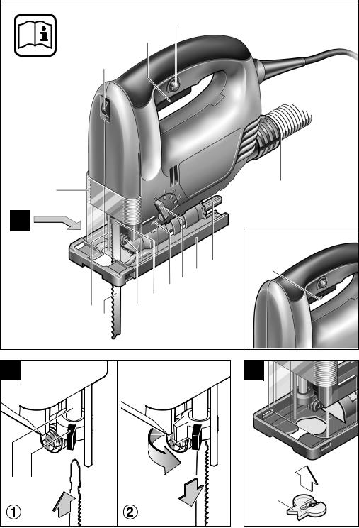
Geräteelemente
1Stellrad Hubzahlvorwahl
2Ein-Aus-Schalter
3Feststellknopf für Ein-Aus-Schalter
4Ausblasöffnung/Absaugschlauch*
5Spannhebel für Fußplatte (PST 850 PE)
6Fußplatte
7Hebel für Pendelhub-Einstellung
8Schalter für Späneblasvorrichtung (PST 750 PE/PST 850 PE)
9SDS-Hebel für Sägeblattentriegelung
10Führungsrolle
11Sägeblatt*
12Berührungsschutz
13Abdeckhaube für Absaugung
14Hubstange
15Spanreißschutz*
16Skala Schnittwinkel
17Schraube
18Winkelmesser**
19Gewindebohrung
20Vordere Aussparung
21Halterung
22Parallelanschlag/Kreisschneider*
*Zubehör
**handelsüblich (nicht im Lieferumfang enthalten) Abgebildetes oder beschriebenes Zubehör gehört teilweise nicht zum Lieferumfang.
|
2 609 932 299 • (03.03) T |
Deutsch–1 |

Zu Ihrer Sicherheit
Gefahrloses Arbeiten mit dem Gerät ist nur möglich, wenn Sie die Bedienungsanleitung und die Sicherheitshinweise vollständig lesen und die darin enthaltenen Anweisungen strikt befolgen.
Zusätzlich müssen die allgemeinen Sicherheitshinweise im beigefügten Heft befolgt werden.
Lassen Sie sich vor dem ersten Gebrauch praktisch einweisen.
■Wird bei der Arbeit das Netzkabel beschädigt oder durchtrennt, Kabel nicht berühren und sofort den Netzstecker ziehen. Gerät niemals mit beschädigtem Kabel benutzen.
■Geräte, die im Freien verwendet werden, über einen Fehlerstrom-(FI-)Schutzschalter mit maximal 30 mA Auslösestrom anschließen. Das Gerät nicht bei Regen oder Nässe verwenden.
■Schutzbrille tragen.
■Asbesthaltiges Material darf nicht bearbeitet werden.
■Kabel immer nach hinten vom Gerät wegführen.
■Sichern Sie das Werkstück. Ein mit Spannvorrichtungen oder Schraubstock festgehaltenes Werkstück ist sicherer gehalten als mit Ihrer Hand.
■Das Gerät nur eingeschaltet gegen das Werkstück führen.
■Beim Arbeiten nie Hand oder Finger vor dem Sägeblatt führen.
ASägeblatt einsetzen/wechseln
■Vor allen Arbeiten am Gerät Netzstecker ziehen.
■Zum Einsetzen und Wechseln des Sägeblattes 11 wird das Tragen von Schutzhandschuhen empfohlen.
Sägeblatt einsetzen
Sägeblatt (Zähne in Schnittrichtung) bis zum Einrasten in die Hubstange 14 einschieben. Der SDS-Spannhe- bel 9 springt nach hinten, und das Sägeblatt wird verriegelt.
Beim Einsetzen des Sägeblattes darauf achten, dass der Sägeblattrücken in der Rille der Führungsrolle 10 liegt.
Sägeblatt auswerfen
Zum Auswerfen des Sägeblattes den SDS-Hebel 9 nach vorn in die Aufnahmeposition drehen. Das Sägeblatt wird gelöst und ausgeworfen.
Staub-/Späneabsaugung
■Beim Arbeiten entstehende Stäube können gesundheitsschädlich, brennbar oder explosiv sein. Geeignete Schutzmaßnahmen sind erforderlich.
Zum Beispiel: Manche Stäube gelten als Krebs erregend. Geeignete Staub-/Späneabsaugung verwenden und Staubschutzmaske tragen.
■Leichtmetallstaub kann brennen oder explodieren. Arbeitsplatz stets sauber halten, weil Materialmischungen besonders gefährlich sind.
Abdeckhaube
■Die Schnittbahn muss oben und unten frei sein von Hindernissen.
■Beim Sägen muss die Fußplatte 6 auf ganzer Fläche sicher aufliegen.
■Beim Bearbeiten kleiner oder dünner Werkstücke stabile Unterlage bzw. Sägetisch verwenden (Zubehör).
■Nur scharfe, einwandfreie Sägeblätter verwenden. Rissige, verbogene oder unscharfe Sägeblätter sofort auswechseln.
■Nach Beendigung des Arbeitsvorganges Gerät ausschalten und Sägeblatt erst dann aus dem Schnitt ziehen und ablegen, wenn dieses zum Stillstand gekommen ist (Rückschlaggefahr).
■Das Gerät vor dem Ablegen immer ausschalten und warten, bis das Gerät zum Stillstand gekommen ist.
■Sägeblätter nach dem Ausschalten nicht durch seitliches Gegendrücken abbremsen.
■Niemals Kindern die Benutzung des Gerätes gestatten.
■Bosch kann nur dann eine einwandfreie Funktion des Gerätes zusichern, wenn das für dieses Gerät vorgesehene Original-Zubehör verwendet wird.
Bei Einsatz der Staubabsaugung die Abdeckhaube 13 immer montieren und ganz nach unten schieben.
Aufsetzen: Abdeckhaube von oben in die Führung einsetzen und bis zum Einrasten nach unten schieben.
Abnehmen: Abdeckhaube seitlich fassen und nach oben abziehen.
Anschluss eines Staubsaugers
(Zubehörseiten)
Den Absaugschlauch (Ø 19 mm, Zubehör) direkt an der Ausblasöffnung 4 anschließen.
Der Staubsauger muss für den zu bearbeitenden Werkstoff geeignet sein.
Beim Absaugen von besonders gesundheitsgefährdenden, Krebs erzeugenden, trockenen Stäuben ist ein Spezialsauger zu verwenden.
In Deutschland werden für Holzstäube auf Grund TRGS 553 geprüfte Absaugeinrichtungen gefordert, die interne Absaugeinrichtung darf im gewerblichen Bereich nicht verwendet werden. Für andere Materialien muss der gewerbliche Betreiber die speziellen Anforderungen mit der zuständigen Berufsgenossenschaft klären.
|
2 609 932 299 • (03.03) T |
Deutsch–2 |
Inbetriebnahme
Netzspannung beachten!
Die Spannung der Stromquelle muss mit den Angaben auf dem Typenschild des Gerätes übereinstimmen. Mit 230 V gekennzeichnete Geräte können auch an 220 V betrieben werden.
Ein-Aus-Schalten
Zur Inbetriebnahme des Gerätes den Ein-Aus- Schalter 2 drücken.
Zum Feststellen den Ein-Aus-Schalter 2 in gedrücktem Zustand mit dem Feststellknopf 3 arretieren.
Zum Ausschalten des Gerätes den Ein-Aus-Schalter 2 loslassen bzw. drücken und loslassen.
Stufenlose Hubzahlregulierung
Leichter Druck auf den Ein-Aus-Schalter 2 bewirkt eine kleine Hubzahl. Mit zunehmendem Druck wird die Hubzahl erhöht.
Hubzahlvorwahl
Mit dem Stellrad 1 lässt sich die erforderliche Hubzahl (auch während des Laufes) vorwählen.
Die erforderliche Hubzahl ist vom Werkstoff und den Arbeitsbedingungen abhängig und kann durch praktischen Versuch ermittelt werden.
Späneblasvorrichtung (PST 750 PE/PST 850 PE)
Mit dem Luftstrom der Späneblasvorrichtung 8 kann die Schnittlinie von Spänen frei gehalten werden.
Späneblasvorrichtung ein:
Für Arbeiten in Holz, Kunststoff u.Ä. mit großem Spanabtrag.
Späneblasvorrichtung aus:
Für Arbeiten in Metall und Verwendung von Kühlund Schmierflüssigkeit.
Pendelung einstellen
Die in vier Stufen einstellbare Pendelung ermöglicht eine optimale Anpassung von Schnittgeschwindigkeit, Schnittleistung und Schnittbild an das zu bearbeitende Material.
Die Pendelung kann mit dem Einstellhebel 7 (auch bei laufender Maschine) eingestellt werden.
|
Stufe 0: |
keine Pendelung |
|
Stufe I: |
kleine Pendelung |
|
Stufe II: |
mittlere Pendelung |
|
Stufe III: |
große Pendelung |
Es wird empfohlen:
–die Pendelstufe umso kleiner zu wählen bzw. die Pendelung abzuschalten, je feiner und sauberer die Schnittkante werden soll,
–bei der Bearbeitung von dünnen Werkstoffen wie z.B. Blechen die Pendelung auszuschalten,
–in harten Werkstoffen wie z.B. Stahl mit kleiner Pendelung zu arbeiten,
–in weichen Materialien und beim Schnitt in Faserrichtung mit maximaler Pendelung zu arbeiten.
Die optimale Einstellung kann durch praktischen Versuch ermittelt werden.
C / D Schnittwinkel einstellen
PST 650 PE/PST 750 PE
Die Schraube 17 lösen, und die Fußplatte 6 leicht in Richtung Sägeblatt schieben. Die Fußplatte ist beidseitig um 45° schwenkbar.
Beliebige Schnittwinkel lassen sich mit einem Winkelmesser 18 exakt einstellen.
Für die Einstellung präziser Gehrungswinkel besitzt die Fußplatte eine Skala 16 mit Einrastpunkten in 15°- Schritten. Die geschwenkte Fußplatte bis zum Einrasten in Richtung Ausblasöffnung schieben.
Die Schraube 17 anschließend wieder festziehen.
PST 850 PE
Den Spannhebel 5 aus der Fußplatte 6 herausschwenken und die Fußplatte durch Linksdrehen des Spannhebels lösen.
Danach die Fußplatte 6 leicht in Richtung Sägeblatt schieben. Die Fußplatte ist beidseitig um 45° schwenkbar.
Beliebige Schnittwinkel lassen sich mit einem Winkelmesser 18 exakt einstellen.
Für die Einstellung präziser Gehrungswinkel besitzt die Fußplatte eine Skala 16 mit Einrastpunkten in 15°- Schritten. Die geschwenkte Fußplatte bis zum Einrasten in Richtung Ausblasöffnung schieben.
Den Spannhebel 5 anschließend durch Rechtsdrehen wieder festziehen und zurück in die Fußplatte schwenken. Darauf achten, dass der Spannhebel vollständig in der Fußplatte 6 versenkt ist.
|
2 609 932 299 • (03.03) T |
Deutsch–3 |

D / E Fußplatte versetzen
Für randnahes Sägen kann die Fußplatte nach hinten versetzt werden.
–Mit versetzter Fußplatte kann der Schnittwinkel nicht verändert werden.
–Der Kreisschneider/Parallelanschlag 22 sowie der Spanreißschutz 15 können nicht verwendet werden.
PST 650 PE/PST 750 PE
Die Schraube 17 vollständig herausdrehen. Die Fußplatte abheben und so versetzen, dass die Schraube 17 mit der Halterung 21 in die vordere Aussparung 20 der Fußplatte eingesetzt und wieder in die Gewindebohrung 19 eingedreht werden kann.
Vor dem Festziehen der Schraube 17 die Fußplatte bis zum Einrasten nach hinten drücken.
PST 850 PE
Den Spannhebel 5 aus der Fußplatte 6 herausschwenken und die Fußplatte durch Linksdrehen des Spannhebels lösen.
Die Fußplatte 6 bis zum Anschlag in Richtung Ausblasöffnung verschieben.
Den Spannhebel 5 anschließend durch Rechtsdrehen wieder festziehen und zurück in die Fußplatte schwenken. Darauf achten, dass der Spannhebel vollständig in der Fußplatte 6 versenkt ist.
Tipps
Nach längerem Arbeiten mit kleiner Hubzahl die Maschine ohne Sägeblatt zur Abkühlung ca. 3 Minuten mit maximaler Hubzahl im Leerlauf drehen lassen.
Für enge Kurven schmale Sägeblätter verwenden.
Beim Sägen von Metall o.Ä. entlang der Schnittlinie Kühlbzw. Schmiermittel auftragen.

 /
/
 Parallelanschlag/Kreisschneider (Zubehör)
Maximale Materialstärke: 30 mm
Tauchsägen
Es dürfen nur weiche Werkstoffe wie Holz, Gasbeton, Gipskarton o.Ä. im Tauchsägeverfahren bearbeitet werden!
Nur kurze Sägeblätter verwenden.
Das Gerät mit der vorderen Kante der Fußplatte auf das Werkstück aufsetzen und einschalten. Das Gerät fest gegen das Werkstück drücken, und das Sägeblatt langsam in das Werkstück eintauchen.
Sobald die Fußplatte ganzflächig aufliegt, entlang der Schnittlinie weitersägen.
B Spanreißschutz
Um das Ausreißen der Oberfläche beim Sägen von Holz zu verhindern, den Spanreißschutz von unten in die Fußplatte 6 einsetzen.
Der Spanreißschutz kann nur für bestimmte Sägeblatttypen verwendet werden.
|
2 609 932 299 • (03.03) T |
Deutsch–4 |

Wartung und Reinigung
■Vor allen Arbeiten am Gerät Netzstecker ziehen.
■Gerät und Lüftungsschlitze stets sauber halten, um gut und sicher zu arbeiten.
Um Funktionsstörungen zu vermeiden, stark stauberzeugende Materialien nicht von unten bzw. über Kopf bearbeiten. Die Sägeblattaufnahme regelmäßig reinigen, z.B. durch leichtes Ausklopfen des Gerätes auf einer ebenen Fläche.
■Bei extremen Einsatzbedingungen kann sich bei der Bearbeitung von Metallen leitfähiger Staub im Innern des Gerätes absetzen. Die Schutzisolierung des Gerätes kann beeinträchtigt werden. Es empfiehlt sich in solchen Fällen die Verwendung einer stationären Absauganlage, häufiges Ausblasen der Lüftungsschlitze und das Vorschalten eines Fehler- strom-Schutzschalters (FI).
Die Führungsrolle 10 gelegentlich mit einem Tropfen Öl schmieren und auf Abnutzung überprüfen. Ist sie abgenutzt, muss sie erneuert werden.
Sollte das Gerät trotz sorgfältiger Herstellund Prüfverfahren einmal ausfallen, ist die Reparatur von einer autorisierten Kundendienststelle für Bosch-Elektro- werkzeuge ausführen zu lassen.
Bei allen Rückfragen und Ersatzteilbestellungen bitte unbedingt die 10-stellige Bestellnummer laut Typenschild des Gerätes angeben.
Konformitätserklärung
Wir erklären in alleiniger Verantwortung, dass dieses Produkt mit den folgenden Normen oder normativen Dokumenten übereinstimmt:
EN 50 144 gemäß den Bestimmungen der Richtlinien 89/336/EWG, 98/37/EG.
|
Dr. Egbert Schneider |
Dr. Eckerhard Strötgen |
|
Senior Vice President |
Head of Product |
|
Engineering |
Certification |
Robert Bosch GmbH, Geschäftsbereich Elektrowerkzeuge
Änderungen vorbehalten
Umweltschutz
Rohstoffrückgewinnung statt Müllentsorgung
Gerät, Zubehör und Verpackung sollten einer umweltgerechten Wiederverwertung zugeführt werden.
Diese Anleitung ist aus chlorfrei gefertigtem RecyclingPapier hergestellt.
Zum sortenreinen Recycling sind Kunststoffteile gekennzeichnet.
In Deutschland können nicht mehr gebrauchsfähige Geräte zum Recycling beim Handel abgegeben oder (ausreichend frankiert) direkt eingeschickt werden an:
Recyclingzentrum Elektrowerkzeuge
Osteroder Landstr. 3
37589 Kalefeld
|
2 609 932 299 • (03.03) T |
Deutsch–5 |

Product Specifications
|
Jigsaw |
PST 650 PE |
PST 750 PE |
PST 850 PE |
|||||||
|
Order number |
0 603 381 7.. |
0 603 382 7.. |
0 603 383 7.. |
|||||||
|
Rated input power |
[W] |
470 |
600 |
620 |
||||||
|
Output power |
[W] |
280 |
360 |
370 |
||||||
|
Stroke rate at no load |
[per min] |
500–3100 |
500–3100 |
500–3100 |
||||||
|
Stroke |
[mm] |
23 |
23 |
23 |
||||||
|
Stroke rate selection |
● |
● |
● |
|||||||
|
Pendelum action |
● |
● |
● |
|||||||
|
Maximum cutting depth |
||||||||||
|
in wood |
[mm] |
68 |
75 |
85 |
||||||
|
in aluminium |
[mm] |
15 |
18 |
18 |
||||||
|
in non-alloyed steel |
[mm] |
4 |
6 |
8 |
||||||
|
Bevel cuts (left/right) |
[°] |
0–45 |
0–45 |
0–45 |
||||||
|
Weight without mains cable approx. |
[kg] |
1.9 |
2.4 |
2.4 |
||||||
|
Protection class |
/ II |
/ II |
/ II |
Please observe the order number of your machine. The trade names of the individual machines may vary.
Noise/Vibration Information
Measured values determined according to EN 50 144.
The A-weighted sound pressure levels of the machines are typically:
|
PST 650 |
PE |
82 dB(A) |
|
PST 750 |
PE/PST 850 PE |
84 dB(A) |
The noise level when working can exceed 85 dB(A).
Wear ear protection!
PST 650 PE: The typically weighted acceleration is 5 m/s2.
PST 750 PE/PST 850 PE: The typical hand-arm vibration is below 2.5 m/s2.
Intended Use
The machine is intended for making separating cuts and cutouts in wood, plastic, metal, ceramic plates and rubber while resting firmly on the workpiece. It is suitable for straight and curved cuts with bevel angles to 45°. The saw blade recommendations are to be observed.
Product Elements
1Stroke rate selection thumbwheel
2On/off switch
3Locking button for on/off switch
4Blow-out opening/Vacuum hose*
5Clamping lever for base plate (PST 850 PE)
6Base plate
7Lever for pendulum stroke adjustment
8Switch for sawdust blowing device (PST 750 PE/PST 850 PE)
9SDS lever for saw blade release
10Guide roller
11Saw blade*
12Contact protector
13Dust cover for vacuuming
14Stroke rod
15Splintering protector*
16Cutting angle scale
17Screw
18Protractor**
19Threaded hole
20Front cut-out
21Retainer
22Parallel Guide/Circle Cutter*
*Optional accessories
**Commercially available (not included in the delivered items)
Not all the accessories illustrated or described are included in standard delivery.
|
2 609 932 299 • (03.03) T |
English–1 |

For Your Safety
Working safely with this machine is possible only when the operating and safety information are read completely and the instructions contained therein are strictly followed.
In addition, the general safety notes in the enclosed booklet must be observed.
Before using for the first time, ask for a practical demonstration.
■If the cable is damaged or cut through while working, do not touch the cable but immediately pull the mains plug. Never use the machine with a damaged cable.
■Connect machines that are used in the open via a residual current device (RCD) with an actuating current of 30 mA maximum. Do not operate the machine in rain or moisture.
■Wear safety glasses.
■Working with material containing asbestos is not permitted.
■Always direct the cable to the rear away from the machine.
■Secure the workpiece. A workpiece clamped with clamping devices or in a vice is held more secure than by hand.
■Apply the machine to the workpiece only when switched on.
■When working, never place a hand or fingers in front of the saw blade.
■The cutting path must be free of obstacles both above and below.
■When sawing, the complete surface of the base plate 6 must be in secure contact.
■For the working of smaller or thin workpieces, use a stable foundation or a saw table (accessory).
■Use only sharp, flawless saw blades. Replace immediately cracked, bent or dull saw blades.
■When the cut is completed, switch off the machine and then pull the saw blade out of the cut only after it has come to a standstill (danger of kick-back).
■Always switch the machine off and wait until it has come to a standstill before placing it down.
■After switching off, do not brake the saw blade to a stop by applying side pressure.
■Never allow children to use the machine.
■Bosch is able to ensure flawless functioning of the machine only if the original accessories intended for it are used.
AInserting/
Changing the Saw Blade
■Before any work on the machine itself, pull the mains plug.
■For inserting or changing the saw blade 11, the wearing of protective gloves is recommended.
Inserting the Saw Blade
Insert the saw blade (teeth in the cutting direction) into the stroke rod 14 until it latches. The SDS clamping lever 9 springs to the rear and locks the saw blade.
Take care when inserting the saw blade that the rear edge of the saw blade rests in the groove of the guide roller 10.
Ejecting the Saw Blade
To eject the saw blade, turn the SDS lever 9 to the front in the insertion position. The saw blade is released and ejected.
Dust/Chip Vacuuming
■Dust produced while working can be detrimental to health, inflammable or explosive. Suitable protection measures are required.
Examples: Some dusts are considered to be carcinogenic. Use suitable dust/chip extraction and wear a dust protection mask.
■Light metal dust can burn or explode. Always keep the work place clean since material mixtures are especially dangerous.
Cover Guard
When using a vacuum cleaner, always mount the dust cover 13 and slide it completely downward.
Attaching: Insert the cover guard from above into the guide and slide downward until it latches.
Removing: Take hold of the cover guard on the sides and pull off in the upward direction.
Connection for a Vacuum Cleaner
(Accessory pages)
Connect the vacuuming hose (19 mm dia., accessory) directly to the blow-out opening 4.
The vacuum cleaner must be suitable for the material to be worked.
When vacuuming dry dust that is especially detrimental to health or carcinogenic, use a special vacuum cleaner.
|
2 609 932 299 • (03.03) T |
English–2 |
![]()
Putting into Operation
Ensure that the mains voltage is correct!
The voltage of the power source must agree with the value given on the nameplate of the machine. Machines designated for 230 V can also be operated with 220 V.
Switching On/Off
To switch on the machine, press the on/off switch 2.
Lock the depressed on/off switch 2 by pressing the lock-on button 3.
To switch off the machine, release the on/off switch 2 or push and then release it.
It is recommended that:
–The finer and cleaner the cut edge should be, the smaller the pendulum action step selected should be or the pendulum action switched off.
–The pendulum action be switched off for working with thin materials such as sheet metal, for example.
–The small pendulum action step be used in hard materials such as steel, for example.
–In soft materials and for cuts in the direction of the grain, the maximum pendulum action be used.
The optimal setting can be determined in practice.
|
Continuously Variable Stroke Rate Adjustment |
C |
/ |
D |
Adjusting the Cutting Angle |
||
|
Light application of pressure on the on/off switch 2 re- |
PST 650 PE/PST 750 PE |
|||||
|
sults in a low stroke rate. Increasing pressure results in |
||||||
|
Loosen the screw 17 and slide the base plate 6 for- |
||||||
|
a higher stroke rate. |
||||||
|
ward somewhat in the direction of the saw blade. The |
||||||
|
base plate can be swung to both sides by 45°. |
Stroke Rate Preselection
The required stroke rate can be preselected (also during operation) using the thumbwheel 1.
The required stroke rate is dependent on the material and the working conditions and can be determined by a practical trial.
Sawdust Blower (PST 750 PE/PST 850 PE)
With the air stream of the sawdust blowing device 8, the cutting line can be kept free of dust.
Blower effect switched on:
For working with wood, plastic and other materials that produce large amounts of dust.
Blower effect switched off:
For working with metals and when cooling or lubricating agents are used.
Pendelum Action Setting
The pendulum action that is adjustable in four steps makes possible the optimum adaptation of cutting speed and performance as well as cutting pattern to the material being worked.
The pendulum action can be set with the adjustment lever 7 (also when the machine is running).
Any cutting angle can be set exactly with a protractor 18.
For the setting of precise bevel angles, the base plate has a scale 16 with detent points in 15° steps. Slide the rotated base plate in the direction of the blow-out opening until it latches.
After adjusting, retighten the screw 17.
PST 850 PE
Swing the clamping lever 5 out of the base plate 6 and loosen the base plate by turning the clamping lever anti-clockwise.
Then slide the base plate 6 somewhat in the direction of the saw blade. The base plate can be swung to both sides by 45°.
Any cutting angle can be set exactly with a protractor 18.
For the setting of precise bevel angles, the base plate has a scale 16 with detent points in 15° steps. Slide the rotated base plate in the direction of the blow-out opening until it latches.
Retighten the clamping lever 5 by turning clockwise and swing back into the base plate. Take care that the clamping lever is completely sunk into the base plate 6.
|
Step 0: |
No pendulum action |
|
Step I: |
Small pendulum action |
|
Step II: |
Medium pendulum action |
|
Step III: |
Large pendulum action |
|
2 609 932 299 • (03.03) T |
English–3 |

|
D |
/ |
E |
Offsetting the Foot Plate |
Tips |
||
For sawing close to edges, the foot plate can be offset to the rear.
–With the base plate repositioned, the cutting angle cannot be changed.
–The circle cutter/parallel guide 22 as well as the splintering protector 15 cannot be used.
PST 650 PE/PST 750 PE
Unscrew the screw 17 completely. Lift off the base plate and reposition so that the screw 17 with the retainer 21 fits in the front cut-out 20 of the base plate and can be screwed into the threaded hole 19.
Before tightening the screw 17, press the base plate to the rear until it latches.
PST 850 PE
Swing the clamping lever 5 out of the base plate 6 and loosen the base plate by turning the clamping lever anti-clockwise.
Slide the base plate 6 to the stop in the direction of the blow-out opening.
Retighten the clamping lever 5 by turning clockwise and swing back into the base plate. Take care that the clamping lever is completely sunk into the base plate 6.
After working for a long period with a low stroke rate, allow the machine to cool by running for approx. 3 minutes without a saw blade and at maximum stroke rate.
For narrow curves, use a thin saw blade.
When sawing metal or similar material, apply a cooling or lubricating agent along the cutting line.

 /
/
 Parallel Guide/Circle Cutter (Accessory)
Maximum material thickness: 30 mm
Plunge Sawing
Plunge cutting may be used only on soft materials such as wood, aerated concrete, gypsum plaster boards, etc.!
Use only short saw blades.
Place the front edge of the base plate on the workpiece and switch on. Press the machine firmly against the workpiece and plunge the saw blade slowly into the workpiece.
As soon as the complete surface of the base plate rests on the work piece, continue to saw along the cutting line.
B Splintering Protector
To prevent the splintering of the surface when sawing wood, insert the splintering protector into the base plate 6 from below.
The splintering protector can be used only with certain types of saw blades.
|
2 609 932 299 • (03.03) T |
English–4 |
Maintenance and Cleaning
■Before any work on the machine itself, pull the mains plug.
■For safe and efficient working, always keep the machine and the ventilation slots clean.
To avoid malfunctions, do not work with materials that produce large amounts of dust from below or overhead. Clean the saw blade holder regularly, for example, by lightly tapping the machine on a flat surface.
■In extreme working conditions, conductive dust can accumulate in the interior of the machine when working with metal. The protective insulation of the machine can be degraded. The use of a stationary extraction system is recommended in such cases as well as the frequent blowing out of the ventilation slots and the installation of a residual current circuit breaker (RCD).
Lubricate the guide roller 10 from time to time with a drop of oil and check for wear. If it is worn, it must be replaced.
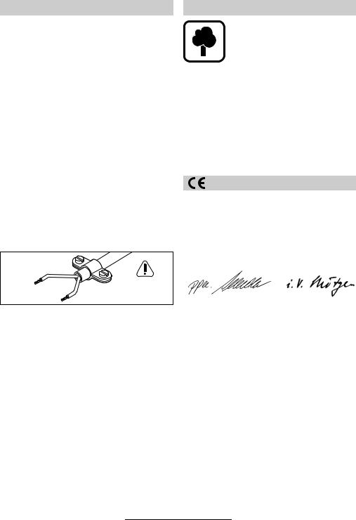
WARNING
Important instructions for connecting a new 3- pin plug to the 2-wire cable.
The wires in the cable are coloured according to the following code:
Strain relief
Live = brown
|
To be fitted |
|
|
by qualified |
|
|
Neutral = blue |
professionals only |
Do not connect the blue or brown wire to the earth terminal of the plug.
Important: If the plug on the cable of this machine must be replaced, dispose of the old plug to prevent misuse.
If the machine should fail despite the care taken in manufacture and testing, repair should be carried out by an authorised customer services agent for Bosch power tools.
For all correspondence and spare parts orders, always include the 10-digit order number of the machine.
Environmental Protection
Recycle raw materials instead of disposing as waste.
The machine, accessories and packaging should be submitted for environment-friendly recycling.
These instructions are printed on recycled paper manufactured without chlorine.
The plastic components are labelled for categorised recycling.
Declaration of Conformity
We declare under our sole responsibility that this product is in conformity with the following standards or standardization documents:
EN 50 144 according to the provisions of the directives 89/336/EEC, 98/37/EC.
|
Dr. Egbert Schneider |
Dr. Eckerhard Strötgen |
|
Senior Vice President |
Head of Product |
|
Engineering |
Certification |
Robert Bosch GmbH, Geschäftsbereich Elektrowerkzeuge
Specification subject to alteration without notice
|
2 609 932 299 • (03.03) T |
English–5 |

Caractéristiques techniques
|
Scie sauteuse |
PST 650 PE |
PST 750 PE |
PST 850 PE |
|||||||
|
Référence |
0 603 381 7.. |
0 603 382 7.. |
0 603 383 7.. |
|||||||
|
Puissance absorbée |
[W] |
470 |
600 |
620 |
||||||
|
Puissance débitée |
[W] |
280 |
360 |
370 |
||||||
|
Cadence de coupe à vide |
[min-1] |
500–3100 |
500–3100 |
500–3100 |
||||||
|
Course |
[mm] |
23 |
23 |
23 |
||||||
|
Présélection de la cadence de coupe |
● |
● |
● |
|||||||
|
Mouvement pendulaire |
● |
● |
● |
|||||||
|
Profondeur de coupe max. |
||||||||||
|
dans le bois |
[mm] |
68 |
75 |
85 |
||||||
|
dans l’aluminium |
[mm] |
15 |
18 |
18 |
||||||
|
dans l’acier, non allié |
[mm] |
4 |
6 |
8 |
||||||
|
Coupes biaises (gauche/droite) |
[°] |
0–45 |
0–45 |
0–45 |
||||||
|
Poids sans cordon d’alimentation, env. |
[kg] |
1,9 |
2,4 |
2,4 |
||||||
|
Catégorie de protection |
/ II |
/ II |
/ II |
Faire attention au numéro de référence de la machine. Les désignations commerciales des différentes machines peuvent varier.
Bruits et vibrations
Valeurs de mesures obtenues conformément à la norme européenne 50 144.
Typiquement, le niveau de pression acoustique pondéré A s’élève :
|
PST 650 |
PE |
82 dB(A) |
|
PST 750 |
PE/PST 850 PE |
84 dB(A) |
Le niveau sonore en fonctionnement peut dépasser 85 dB(A).
Se munir d’un casque anti-bruit !
PST 650 PE: L’accélération réelle mesurée est 5 m/s2.
PST 750 PE/PST 850 PE: La vibration de l’avant-bras est inférieure à 2,5 m/s2.
Utilisation conforme
L’appareil est conçu pour effectuer, sur un support rigide, des découpes et coupes dans le bois, les matières plastiques, le métal, le caoutchouc et les plaques en céramique. Il est approprié pour des coupes droites et curvilignes avec des angles d’onglet jusqu’à 45°. Respecter les recommandations relatives aux lames de scie appropriées.
Eléments de l’appareil
1Molette de réglage de la cadence de coupe
2Interrupteur Marche/Arrêt
3Bouton de verrouillage de l’interrupteur Marche/Arrêt
4Tubulure de soufflage/Tuyau flexible d’aspiration*
5Levier de blocage pour plaque de base (PST 850 PE)
6Plaque de base
7Levier pour réglage du mouvement pendulaire
8Commutateur pour dispositif de soufflerie (PST 750 PE/PST 850 PE)
9Levier SDS pour déverrouillage de la lame de scie
10Guide-lame à rouleau
11Lame de scie*
12Protège-mains
13Capot pour aspiration
14Porte-lame
15Pare-éclats*
16Echelle graduée, pour découpes en onglets
17Vis
18Rapporteur**
19Filetage
20Evidement avant
21Fixation
22Butée parallèle/Butée pour coupe circulaire*
*Accessoires
**Disponible dans le commerce (non fourni avec l’appareil)
Les accessoires reproduits ou décrits ne sont pas tous compris dans les fournitures.
|
2 609 932 299 • (03.03) T |
Français–1 |

Pour votre sécurité
Pour travailler sans risque avec cet appareil, lire intégralement au préalable les instructions de service et les remarques concernant la sécurité. Respecter scrupuleusement les indications et les consi-
gnes qui y sont données. Respecter en plus les indications générales de sécurité se trouvant dans le cahier ci-joint. Avant la première mise en service, laisser quelqu’un connaissant bien cet appareil vous instruire de la manière de s’en servir.
■Si le cordon d’alimentation électrique est endommagé ou rompu pendant le travail, ne pas y toucher. Extraire immédiatement la fiche du cordon d’alimentation hors de la prise électrique. Ne jamais utiliser un appareil dont le cordon d’alimentation est endommagé.
■Brancher les appareils qui sont utilisés à l’extérieur sur un disjoncteur différentiel avec un courant de déclenchement maximal de 30 mA. Ne pas utiliser l’appareil par temps de pluie ni dans un endroit humide.
■Porter des lunettes de protection.
■Ne jamais travailler de matériau contenant de l’amiante.
■Toujours ramener les câbles à l’arrière de l’appareil.
■Bloquer la pièce à travailler. Une pièce à travailler serrée par des dispositifs de serrage ou dans un étau est fixée de manière plus sûre que lorsqu’elle est immobilisée à la main.
■N’appliquer l’appareil contre la pièce à usiner que lorsque celui-ci est en marche.
■Ne jamais passer la main ou le doigt devant la lame tant que celle-ci est en mouvement.
■La ligne de coupe doit être exempte d’obstacles sur le plan supérieur comme sur le plan inférieur.
■Pendant le sciage, la plaque de base 6 de l’appareil doit reposer de façon sûre sur toute sa surface.
■Pour travailler de petites pièces ou des pièces minces, utiliser un support stable ou une table de sciage (accessoire).
■N’utiliser que des lames de scie affûtées et en parfait état. Remplacer immédiatement les lames de scie fissurées, tordues ou mal affûtées.
■Après avoir terminé une passe de découpe, commencer par arrêter l’appareil. Ne retirer la lame de scie hors du trait de coupe qu’après avoir attendu son immobilisation complète (risque de contreréaction violente).
■Avant de déposer l’appareil, toujours le mettre hors fonctionnement et attendre l’arrêt total de l’appareil.
■Après avoir commuté l’interrupteur principal sur la position « Arrêt », ne pas tenter de précipiter l’immobilisation de la lame de scie par pression latérale.
■Ne jamais laisser des enfants utiliser cet appareil.
■Bosch ne peut garantir un fonctionnement impeccable que si les accessoires Bosch d’origine prévus pour cet appareil sont utilisés.
AMise en place/changement de lame
■Avant toute intervention sur l’appareil proprement dit, toujours extraire la fiche du cordon d’alimentation hors de la prise électrique.
■Pour mettre en place ou changer de lame 11, il est recommandé d’enfiler des gants de protection.
Montage de la lame de scie
Enfoncer à fond la lame de scie (les dents étant orientées dans la direction de coupe) dans le porte-lame 14. Le levier SDS 9 est repoussé vers l’arrière et la lame est verrouillée.
Lors de la mise en place de la lame de scie, veiller à ce que le dos de la lame prenne place dans la rainure du guide-lame à rouleau 10.
Ejection de la lame de scie
Pour sortir la lame de scie, tourner le levier SDS 9 vers l’avant dans la position de réception. La lame est débloquée et expulsée.
Aspiration des poussières et copeaux
■Les poussières produites pendant le travail peuvent être nocives, inflammables ou explosives. Prendre les conditions de protection qui s’imposent.
Exemple : certaines poussières sont réputées cancérigènes. Utiliser un dispositif approprié d’aspiration des poussières et des copeaux et porter un masque anti-poussières.
■Les poussières de métaux légers peuvent brûler ou exploser. Toujours maintenir propre le poste de travail, les mélanges de matériaux étant particulièrement dangereux.
Capot
En cas d’utilisation du système d’aspiration, toujours mettre en place et repousser le capot 13 vers le bas.
Montage : Monter le capot par le haut dans le guidage et le pousser vers le bas jusqu’à ce qu’il s’encliquette.
Démontage : Prendre le capot par les côtés et le retirer vers le haut.
|
2 609 932 299 • (03.03) T |
Français–2 |

Raccordement d’un aspirateur
(pages d’accessoires)
Raccorder le tuyau flexible d’aspiration (Ø 19 mm, accessoire) directement sur la tubulure de soufflage 4.
L’aspirateur doit être approprié au matériau à travailler.
Pour l’aspiration de poussières particulièrement nocives, cancérigènes ou sèches, utiliser des aspirateurs spéciaux.
Mise en service
Tenir compte de la tension du secteur !
La tension de la source de courant doit correspondre aux indications figurant sur la plaque signalétique de l’appareil. Les appareils fonctionnant sous 230 V peuvent également être exploités sous 220 V.
Mise en marche/Arrêt
Afin de mettre l’appareil en fonctionnement, appuyer sur l’interrupteur Marche/Arrêt 2.
Afin de bloquer l’interrupteur Marche/Arrêt 2 en position « Marche », appuyer sur le bouton de marche permanente 3.
Afin d’arrêter l’appareil, relâcher l’interrupteur Marche/ Arrêt 2 ou appuyer sur l’interrupteur et le relâcher.
Réglage en continu de la vitesse de coupe
Une légère pression sur l’interrupteur Marche/Arrêt 2 permet d’obtenir une vitesse de coupe faible. Une augmentation de la pression entraîne l’accélération de la vitesse.
Présélection de la vitesse de coupe
La mollette 1 sert à présélectionner la vitesse de la lame. Le réglage peut également être effectué pendant le travail.
La vitesse de travail dépend du matériau à travailler et des conditions de travail et peut être déterminée par des essais pratiques.
Dispositif de soufflerie (PST 750 PE/PST 850 PE)
Le jet d’air commandé par le commutateur pour dispositif de soufflerie 8 permet de maintenir la ligne de coupe libre de copeaux.
Mettre le dispositif de soufflerie en fonctionnement :
Pour les travaux sur bois ou plastiques caractérisés par une production importante de copeaux.
Déconnecter le dispositif de soufflerie :
Pour les travaux de sciage dans le métal et lorsqu’on utilise des agents de refroidissement et de graissage.
Réglage du mouvement pendulaire
Le mouvement pendulaire peut être réglé sur quatre positions, ce qui permet d’adapter toujours au mieux la vitesse, la puissance et le type de coupe au matériau sur lequel le travail est effectué.
Le mouvement pendulaire peut être réglé via le levier de réglage 7 alors même que la machine fonctionne déjà.
Position 0: Sans mouvement pendulaire Position I: Petit mouvement pendulaire Position II: Mouvement pendulaire moyen Position III: Mouvement pendulaire important
Il est recommandé :
–de sélectionner un réglage du mouvement pendulaire d’autant plus faible ou bien de le désactiver à chaque fois que la ligne de coupe doit être plus fine et propre,
–lors du travail sur des matériaux peu épais (tôles, par exemple) de désactiver complètement le mouvement pendulaire,
–sur les matériaux durs (acier, par exemple), de travailler avec un mouvement pendulaire de faible amplitude,
–sur les matériaux plus tendres ainsi que sur les découpes dans le sens des fibres, de travailler avec un mouvement pendulaire maximal.
Trouver le réglage optimal en effectuant des essais pratiques.
C / D Réglage de l’angle de coupe
PST 650 PE/PST 750 PE
Débloquer la vis 17 et déplacer légèrement la plaque de base 6 en direction de la lame de scie. La plaque de base peut pivoter latéralement de 45° des deux côtés.
Un rapporteur 18 permet de régler les angles de coupe quelconques de manière précise.
Pour le réglage précis des découpes à onglets, la plaque de base possède une échelle graduée 16 avec des positions préréglées tous les 15°. Repousser la plaque de base bien pivotée en direction de la tubulure de soufflage, jusqu’à verrouillage.
Ensuite, resserrer la vis 17.
|
2 609 932 299 • (03.03) T |
Français–3 |

PST 850 PE
Basculer le levier de blocage 5 hors de la plaque de base 6. Libérer la plaque de base par une simple rotation vers la gauche (dans le sens inverse des aiguilles d’une montre) du levier de blocage.
Repousser ensuite légèrement la plaque de base 6 en direction de la tubulure de souffage. La plaque de base peut pivoter latéralement de 45° des deux côtés.
Un rapporteur 18 permet de régler les angles de coupe quelconques de manière précise.
Pour le réglage précis des découpes à onglets, la plaque de base possède une échelle graduée 16 avec des positions préréglées tous les 15°. Repousser la plaque de base bien pivotée en direction de la tubulure de soufflage, jusqu’à verrouillage.
Rebloquer le levier 5 par une simple rotation vers la droite (dans le sens des aiguilles d’une montre) puis le basculer dans la plaque de base. Veiller à ce que le levier de blocage soit bien complètement rabattu dans la plaque de base 6.
D / E Déplacement de la plaque de base
Pour un sciage près du bord, il est possible de reculer la plaque de base.
–Une fois la plaque de base déplacée, il n’est plus possible de modifier l’angle de coupe.
–La butée parallèle / butée pour coupe circulaire 22 ainsi que le pare-éclats 15 ne peuvent plus être utilisés.
PST 650 PE/PST 750 PE
Dévisser complètement la vis 17. Soulever la plaque de base et la déplacer de telle manière à ce que la vis 17 et la fixation 21 se retrouvent au niveau de l’évidement avant 20 de la plaque de base et que la vis puisse prendre place dans le filetage 19.
Avant de rebloquer la vis 17, repousser la plaque de base à fond vers l’arrière.
PST 850 PE
Basculer le levier de blocage 5 hors de la plaque de base 6. Libérer la plaque de base par une simple rotation vers la gauche (dans le sens inverse des aiguilles d’une montre) du levier de blocage.
Repousser la plaque de base 6 à fond en direction de la tubulure de soufflage.
Rebloquer le levier 5 par une simple rotation vers la droite (dans le sens des aiguilles d’une montre) puis le basculer dans la plaque de base. Veiller à ce que le levier de blocage soit bien complètement rabattu dans la plaque de base 6.
B Pare-éclats
Pour prévenir l’éclatement de la surface lors du sciage de morceaux de bois, mettre en place le pare-éclats sur la face inférieure de la plaque de base 6.
Le pare-éclats ne peut être mis en place qu’avec certains types de lames de scie.
Conseils
Après un travail assez long à une cadence plutôt faible, laisser fonctionner l’appareil à vide, sans lame de scie, pendant 3 minutes environ à la cadence maximale afin de mieux le refroidir.
Pour découper selon des rayons de courbure réduits, utiliser des lames de scie étroites.
Lors du sciage de métaux ou assimilés, déposer ou amener un peu de liquide de refroidissement ou d’huile de coupe le long de la ligne de découpe.

 /
/
 Butée parallèle/Butée pour coupe circulaire (Accessoire)
Epaisseur maximale du matériau : 30 mm
Sciage en plongée
Le sciage profond ne doit être pratiqué que sur des matériaux tendres (bois, béton cellulaire, placoplâtre ou matériaux assimilés, etc.)!
N’utiliser que des courtes lames de scie.
Positionner l’appareil avec le bord avant de la plaque de base sur la pièce à travailler et mettre l’appareil en fonctionnement. Avec l’appareil exercer une pression contre la pièce et plonger lentement la lame de scie dans la pièce.
Reprendre le sciage le long de la ligne de découpe dès que la plaque de base repose complètement sur la surface.
|
2 609 932 299 • (03.03) T |
Français–4 |

Maintenance et nettoyage
■Avant toute intervention sur l’appareil proprement dit, toujours extraire la fiche du cordon d’alimentation hors de la prise électrique.
■Pour obtenir un travail satisfaisant et sûr, nettoyer régulièrement l’appareil ainsi que ses ouïes de refroidissement.
Pour éviter les dysfonctionnements, ne pas travailler les matériaux générant beaucoup de copeaux par le dessous ou par-dessus la tête. Nettoyer régulièrement la fixation de la lame de scie en frappant légèrement un nombre limité de fois l’appareil sur une surface plane, par exemple.
■Dans certaines conditions d’exploitation délicates, pendant l’usinage de métaux, de la poussière conductrice d’électricité peut se déposer à l’intérieur de l’appareil et ainsi altérer l’isolation de protection de l’appareil. Dans un tel cas de figure, Bosch recommande l’emploi d’un dispositif d’aspiration stationnaire, de souffler fréquemment dans les ouïes de refroidissement et de monter en amont un disjoncteur à courant de défaut (F1).
Lubrifier de temps à autres le guide-lame à rouleau 10 avec une goutte d’huile et contrôler son usure. S’il est trop usé, il doit être remplacé.
Si, malgré tous les soins apportés à la fabrication et au contrôle de l’appareil, celui-ci devait avoir un défaut, la réparation ne doit être confiée qu’à une station de service après-vente pour outillage Bosch agréée.
Pour toute demande de renseignement ou commande de pièces de rechange, nous préciser impérativement le numéro de référence à dix chiffres de la machine.
Instructions de protection de l’environnement
Récupération des matières premières plutôt qu’élimination des déchets
Les machines, comme d’ailleurs leurs accessoires et emballages, doivent pouvoir suivre chacun une voie de recyclage appropriée.
Ce manuel d’instructions a été fabriqué à partir d’un papier recyclé blanchi en l’absence de chlore.
De même, nos pièces plastiques ont été marquées en vue d’un recyclage sélectif des différents matériaux.
Déclaration de conformité
Nous déclarons sous notre propre responsabilité que ce produit est en conformité avec les normes ou documents normalisés :
EN 50 144 conformément aux termes des réglementations 89/336/CEE, 98/37/CE.
|
Dr. Egbert Schneider |
Dr. Eckerhard Strötgen |
|
Senior Vice President |
Head of Product |
|
Engineering |
Certification |
Robert Bosch GmbH, Geschäftsbereich Elektrowerkzeuge
Sous réserve de modifications
|
2 609 932 299 • (03.03) T |
Français–5 |

Características técnicas
|
Sierra de calar |
PST 650 PE |
PST 750 PE |
PST 850 PE |
|||||||
|
Número de pedido |
0 603 381 7.. |
0 603 382 7.. |
0 603 383 7.. |
|||||||
|
Potencia absorbida nominal |
[W] |
470 |
600 |
620 |
||||||
|
Potencia útil |
[W] |
280 |
360 |
370 |
||||||
|
Número de carreras en vacío |
[min-1] |
500–3100 |
500–3100 |
500–3100 |
||||||
|
Carrera |
[mm] |
23 |
23 |
23 |
||||||
|
Preajuste del número de carreras |
● |
● |
● |
|||||||
|
Movimiento pendular |
● |
● |
● |
|||||||
|
máx. profundidad de corte |
||||||||||
|
en madera |
[mm] |
68 |
75 |
85 |
||||||
|
en aluminio |
[mm] |
15 |
18 |
18 |
||||||
|
en acero, no aleado |
[mm] |
4 |
6 |
8 |
||||||
|
Cortes oblicuos (izquierda/derecha) |
[°] |
0–45 |
0–45 |
0–45 |
||||||
|
Peso sin cable, aprox. |
[kg] |
1,9 |
2,4 |
2,4 |
||||||
|
Clase de protección |
/ II |
/ II |
/ II |
Preste atención al nº de pedido de su máquina. Las denominaciones comerciales en ciertas máquinas pueden variar.
Información sobre ruido y vibraciones
Determinación de los valores de medición según norma EN 50 144.
El nivel de sonido típico es de:
|
PST 650 |
PE |
82 dB(A) |
|
PST 750 |
PE/PST 850 PE |
84 dB(A) |
El nivel de ruido, con el aparato trabajando, podrá sobrepasar circunstancialmente 85 dB(A).
¡Usar protectores auditivos!
PST 650 PE: La aceleración típica corresponde a 5 m/s2.
PST 750 PE/PST 850 PE: El nivel de vibraciones típico en la mano/brazo es menor de 2,5 m/s2.
Utilización reglamentaria
El aparato ha sido proyectado para efectuar cortes y recortes sobre una base firme en madera, materiales sintéticos, planchas cerámicas y caucho. Es adecuado para efectuar cortes rectos y en curva con ángulos de inglete hasta 45°. Prestar atención a las hojas de sierra que se recomiendan.
Elementos del aparato
1Rueda para preselección del número de carreras
2Interruptor de deconexión/desconexión
3Botón de enclavamiento para interruptor de conexión/desconexión
4Conexión para aspiración de polvo/manguera de aspiración*
5Palanca de fijación para placa base (PST 850 PE)
6Placa base
7Palanca para ajuste del nivel de movimiento pendular
8Interruptor para soplador de virutas (PST 750 PE/PST 850 PE)
9Palanca SDS para desenclavamiento de la hoja de sierra
10Rodillo guía
11Hoja de sierra*
12Protección contra contacto
13Caperuza para aspiración
14Émbolo portaútiles
15Protección para cortes limpios*
16Escala de ángulo de corte
17Tornillo
18Transpotador de ángulos**
19Rosca
20Ranura delantera
21Soporte
22Tope paralelo/cortador de círculos*
*Accesorios
**Usual en el comercio (no incluido en el material que se adjunta)
Los accesorios ilustrados o descritos pueden no corresponder al material suministrado de serie con el aparato.
|
2 609 932 299 • (03.03) T |
Español–1 |

Para su seguridad
Vd. solamente puede trabajar sin peligro con el aparato si lee íntegramente las instrucciones de manejo y las indicaciones de seguridad, ateniéndose estrictamente a las indicaciones allí comprendidas.
Adicionalmente deberán respetarse las instrucciones de seguridad generales comprendidas en el folleto adjunto.
Déjese instruir prácticamente en el manejo antes de su primer empleo.
■Si llega a dañarse o cortarse el cable de red durante el trabajo, no tocar el cable, sino extraer inmediatamente el enchufe de red. No usar jamás el aparato con un cable deteriorado.
■Conectar los aparatos utilizados en la intemperie a través de un fusible diferencial con una corriente de disparo máxima de 30 mA. No exponer el aparato a la lluvia o humedad.
■Llevar gafas de protección.
■No deben trabajarse materiales que contengan amianto.
■Mantener el cable siempre detrás del aparato.
■Asegure la pieza de trabajo. Una pieza de trabajo fijada con unos dispositivos de sujeción, o en un tornillo de banco, se mantiene sujeta de forma mucho más segura que con la mano.
■Aproximar el aparato a la pieza solamente estando conectado.
■Al trabajar no mantener nunca la mano o los dedos delante de la hoja de sierra.
■La trayectoria de corte debe encontrarse libre de obstáculos en su parte superior e inferior.
■Al aserrar asentar firmemente la placa base 6 en toda su superficie.
■Al trabajar piezas de tamaño reducido o muy delgadas, debe utilizarse una base de asiento estable o una mesa de aserrar (accesorio).
■Emplear únicamente hojas de sierra afiladas y en perfecto estado. Sustituir de inmediato las hojas de sierra fisuradas, deformadas o melladas.
■Al terminar el trabajo, desconectar el aparato y esperar a que se detenga la hoja de sierra antes de extraerla de la ranura de corte y de depositarla (peligro de rebote).
■Siempre desconectar y esperar a que se detenga el aparato, antes de depositarlo.
■No frenar las hojas de sierra después de la desconexión ejerciendo una presión lateral.
■Jamás permita que niños utilicen el aparato.
■Bosch solamente puede garantizar el funcionamiento correcto del aparato si se utilizan los accesorios originales previstos.
AMontaje/cambio de la hoja de sierra
■Antes de cualquier manipulación en el aparato extraer el enchufe de red.
■Para montar o sustituir la hoja de sierra 11 se recomienda ponerse guantes de protección.
Montaje de la hoja de sierra
Insertar hasta el tope la hoja de sierra (con los dientes orientados en el sentido de corte) en el émbolo del portaútiles 14. La palanca de fijación SDS 9 salta hacia atrás quedando enclavada la hoja de sierra.
Al introducir la hoja de sierra, prestar atención a que su lomo penetre en la ranura del rodillo guía 10.
Desmontaje de la hoja de sierra
Para expulsar la hoja de sierra girar hacia adelante la palanca SDS 9 a la posición de inserción. Con ello se libera y expulsa la hoja de sierra.
Aspiración de polvo y virutas
■El polvo producido al trabajar puede ser combustible, explosivo o nocivo para la salud. Por ello se precisan unas medidas de protección adecuadas. Por ejemplo: el polvo de ciertos materiales es cancerígeno. Emplear un dispositivo para aspiración de polvo y virutas adecuado, y colocarse una mascarilla antipolvo.
■El polvo de aleaciones ligeras puede llegar a incendiarse o explotar. Mantener siempre limpio el puesto de trabajo, ya que en caso de mezclarse materiales de diferente tipo, ello resulta especialmente peligroso.
Caperuza
Al aplicar un equipo para aspiración de polvo montar siempre la caperuza 13 y desplazarla completamente hacia abajo.
Montaje: insertar la caperuza desde arriba en la guía y empujarla hacia abajo hasta enclavarla.
Desmontaje: sujetar la caperuza por ambos lados y empujarla hacia arriba.
Conexión de un aspirador
(páginas con accesorios)
Conectar directamente a la conexión 4 la manguera de aspiración (Ø 19 mm, accesorio especial).
El aspirador deberá ser adecuado para el material a trabajar.
Al aspirarse polvo seco cancerígeno, o nocivo para la salud, deberá emplearse un aspirador especial.
|
2 609 932 299 • (03.03) T |
Español–2 |
![]()
Puesta en funcionamiento
¡Cerciorarse de que la tensión de la red sea correcta!
La tensión de la fuente de energía debe coincidir con las indicaciones en la placa de características del aparato. Los aparatos marcados con 230 V pueden funcionar también a 220 V.
Conexión y desconexión
Para la puesta en marcha del aparato presionar el interruptor de conexión/desconexión 2.
Para enclavar el interruptor de conexión/desconexión 2 mantenerlo apretado, y presionar el botón de enclavamiento 3.
Para desconectar el aparato soltar, o presionar y soltar si estuviese enclavado, el interruptor de conexión/ desconexión 2.
Regulación continua del número de carreras
Presionando suavemente sobre el interruptor 2 se consigue un número de carreras reducido. Al aumentar la presión, aumenta el número de carreras.
Preselección del número de carreras
Con la rueda de ajuste 1 puede preajustarse el número de carreras deseado (incluso también durante la operación de la máquina).
El número de carreras requerido depende del material y de las condiciones de trabajo, siendo recomendable, por ello, determinarlo probando.
Soplador de virutas (PST 750 PE/PST 850 PE)
El aire proveniente del soplador de virutas 8 permite mantener despejada la línea de corte.
Soplador de virutas conectado:
Al trabajar madera, plástico, etc. con un gran arranque de virutas.
Soplador de virutas desconectado:
Al trabajar metales y al emplear líquidos refrigerantes y lubricantes.
Ajuste del movimiento pendular
El movimiento pendular, ajustable en cuatro niveles, permite adaptar de forma óptima la velocidad, rendimiento y calidad de corte al tipo de material a trabajar.
La magnitud del movimiento pendular puede ajustarse con la palanca selectora 7 (incluso con la máquina en marcha).
Nivel 0: Movimiento pendular nulo Nivel I: Movimiento pendular ligero Nivel II: Movimiento pendular mediano Nivel III: Movimiento pendular grande
Se recomienda:
–seleccionar un nivel del movimiento pendular menor, o incluso nulo, cuanto más fino o limpio deba resultar el corte.
–desconectar el movimiento pendular, al trabajar materiales delgados como, p.ej., chapas,
–seleccionar un movimiento pendular reducido en materiales duros como, p.ej., el acero,
–trabajar ajustando el movimiento pendular al nivel máximo en materiales blandos y al realizar cortes en el sentido de la fibra.
Se recomienda determinar probando el ajuste óptimo.
C / D Ajuste del ángulo de corte
PST 650 PE/PST 750 PE
Aflojar el tornillo 17 y desplazar levemente la placa base 6 hacia la hoja de sierra. La placa base puede girarse 45° hacia cada lado.
Es posible ajustar exactamente cualquier ángulo de corte con un transportador de ángulos 18.
La placa base dispone de una escala 16 con muescas cada 15°, que permiten ajustar con exactitud los ángulos de inglete. Una vez girada la placa base, desplazarla hacia la boca de expulsión hasta enclavarla.
Apretar seguidamente el tornillo 17.
PST 850 PE
Sacar la palanca de fijación 5 fuera de la placa base 6 y aflojar ésta girando a izquierdas la palanca de fijación.
Seguidamente tirar de la placa base 6 hacia la hoja de sierra. La placa base puede girarse 45° hacia cada lado.
Es posible ajustar exactamente cualquier ángulo de corte con un transportador de ángulos 18.
La placa base dispone de una escala 16 con muescas cada 15°, que permiten ajustar con exactitud los ángulos de inglete. Una vez girada la placa base, desplazarla hacia la boca de expulsión hasta enclavarla.
A continuación, apretar la palanca de fijación 5 girándola a derechas y abatirla dentro de la placa base. Observar que la palanca de fijación quede completamente inmersa en la placa base 6.
|
2 609 932 299 • (03.03) T |
Español–3 |

D / E Desplazamiento de la placa base
Para aserrar muy cerca de los bordes puede desplazarse hacia atrás la placa base.
–Con la placa base desplazada no es posible modificar el ángulo de corte.
–No es posible emplear el cortador de círculos/tope paralelo 22 ni la protección para cortes limpios 15.
PST 650 PE/PST 750 PE
Desenroscar completamente el tornillo 17. Alzar la placa base y desplazarla de forma que el tornillo 17 con el soporte 21 pueda insertarse por la ranura delantera 20 de la placa base para volver a enroscarse en el taladro roscado 19.
Antes de apretar el tornillo 17, presionar hacia atrás la placa base hasta enclavarla.
PST 850 PE
Sacar la palanca de fijación 5 fuera de la placa base 6 y aflojar ésta girando a izquierdas la palanca de fijación.
Desplazar hasta el tope la placa base 6 hacia la boca de expulsión.
A continuación, apretar la palanca de fijación 5 girándola a derechas y abatirla dentro de la placa base. Observar que la palanca de fijación quede completamente inmersa en la placa base 6.
B Protección para cortes limpios
Para evitar que se astille la superficie al aserrar madera, montar desde abajo la protección para cortes limpios en la placa base 6.
La protección para cortes limpios solamente puede emplearse para ciertos tipos de hojas sierra.
Consejos prácticos
Después de haber trabajado prolongadamente con un número de carreras reducido dejar funcionar la máquina sin la hoja de sierra montada aprox. 3 minutos en vacío a revoluciones máximas para refrigerarla.
Para cortes en curva con radios pequeños emplear hojas de sierra estrechas.
Al aserrar metales, o materiales similares, aplicar un medio refrigerante o lubricante a lo largo de la línea de corte.

 /
/ Tope paralelo/cortador de círculos (accesorio)
Grosor máximo del material: 30 mm
Aserrado por inmersión
¡Solamente pueden aserrarse materiales blandos como madera, hormigón gaseado, placas de cartón-yeso o similares por el procedimiento de aserrado por inmersión!
Únicamente emplear hojas de sierra cortas.
Apoyar el canto delantero de la placa base inclinando el aparato hacia arriba, y conectarlo. Presionar firmemente el aparato contra la pieza de trabajo e irlo descendiendo lentamente para que la hoja de sierra vaya penetrando en la pieza de trabajo.
En el momento en que la placa base alcance a asentar sobre toda su superficie, continuar aserrando a lo largo de la línea de corte.
|
2 609 932 299 • (03.03) T |
Español–4 |
 Loading…
| Language | Type | Pages | |
|---|---|---|---|
| English | User Manual | 72 | > Go to the manual |
| German | User Manual | 72 | Go to the manual |
| Dutch | User Manual | 72 | Go to the manual |
| Danish | User Manual | 72 | Go to the manual |
| French | User Manual | 72 | Go to the manual |
| Italian | User Manual | 72 | Go to the manual |
| Portuguese | User Manual | 72 | Go to the manual |
| Swedish | User Manual | 72 | Go to the manual |
| Turkish | User Manual | 72 | Go to the manual |
| Spanish | User Manual | 72 | Go to the manual |
| Norwegian | User Manual | 72 | Go to the manual |
| Finnish | User Manual | 72 | Go to the manual |
473390
Report abuse
Libble takes abuse of its services very seriously. We’re committed to dealing with such abuse according to the laws in your country of residence. When you submit a report, we’ll investigate it and take the appropriate action. We’ll get back to you only if we require additional details or have more information to share.
Product: Bosch PST 850PE
Forumrules
To achieve meaningful questions, we apply the following rules:
- First, read the manual;
- Check if your question has been asked previously;
- Try to ask your question as clearly as possible;
- Did you already try to solve the problem? Please mention this;
- Is your problem solved by a visitor then let him/her know in this forum;
- To give a response to a question or answer, do not use this form but click on the button ‘reply to this question’;
- Your question will be posted here and emailed to our subscribers. Therefore, avoid filling in personal details.
Your question has been posted on this page
Would you like to receive an email when new answers and questions are posted? Please enter your email address.
Универсальный лобзик BOSCH PST

Общие предупреждения о безопасности при работе с электроинструментом
- Прочтите все предупреждения по технике безопасности и все инструкции.
- Несоблюдение предупреждений и инструкций может привести к поражению электрическим током, возгоранию и / или серьезным травмам.
- Сохраните все предупреждения и инструкции для использования в будущем.
- Термин «электроинструмент» в предупреждениях относится к вашему сетевому (проводному) электроинструменту или аккумуляторному (беспроводному) электроинструменту.
Безопасность на рабочем месте
- Следите за чистотой и хорошим освещением рабочего места. Загроможденные или темные места могут стать причиной несчастных случаев.
- Не работайте с электроинструментом во взрывоопасной атмосфере, например, в присутствии легковоспламеняющихся жидкостей, газов или пыли. Электроинструменты создают искры, которые могут воспламенить пыль или пары.
- Не подпускайте детей и посторонних лиц при работе с электроинструментом. Отвлечение внимания может привести к потере контроля.
Электрическая безопасность
- Вилки электроинструмента должны соответствовать розетке. Ни в коем случае не модифицируйте вилку. Не используйте переходные вилки с заземленными электроинструментами. Неизмененные вилки и подходящие розетки снизят риск поражения электрическим током.
- Избегайте контакта тела с заземленными или заземленными поверхностями,
таких как трубы, радиаторы, плиты и холодильники. Существует повышенный риск поражения электрическим током, если ваше тело заземлено или заземлено. - Не подвергайте электроинструменты воздействию дождя или влаги.
- Попадание воды в электроинструмент увеличивает риск поражения электрическим током.
- Не злоупотребляйте шнуром. Никогда не используйте шнур для переноски, тяги или отключения электроинструмента. Держите шнур вдали от источников тепла, масла, острых краев и движущихся частей. Поврежденные или запутавшиеся шнуры увеличивают риск поражения электрическим током.
- При работе с электроинструментом на открытом воздухе используйте удлинитель, подходящий для использования на открытом воздухе. Использование кабеля, подходящего для использования на открытом воздухе, снижает риск поражения электрическим током.
- Если вы используете электроинструмент в рекламеamp Если этого нельзя избежать, используйте источник, защищенный устройством защитного отключения (УЗО). Использование УЗО снижает риск поражения электрическим током.
Личная безопасность
- Будьте бдительны, следите за своими действиями и руководствуйтесь здравым смыслом при работе с электроинструментом. Не пользуйтесь электроинструментом, если вы устали, находитесь под действием наркотиков, алкоголя или лекарств. Момент невнимательности при работе с электроинструментом может привести к серьезным травмам.
- Используйте средства индивидуальной защиты. Всегда надевайте защитные очки. Защитное снаряжение, такое как респиратор, нескользящая защитная обувь, каска или средства защиты органов слуха, используемые в соответствующих условиях, уменьшат количество травм.
- Предотвратить непреднамеренный запуск. Убедитесь, что переключатель находится в выключенном положении, прежде чем подключать к источнику питания и / или аккумуляторной батарее, поднимать или переносить инструмент.
- Переноска электроинструмента, держа палец на переключателе, или включение электроинструмента, у которого переключатель включен, может привести к несчастным случаям.
- Перед включением электроинструмента извлеките регулировочный ключ или гаечный ключ. Гаечный ключ или ключ, оставленный на вращающейся части электроинструмента, может привести к травме.
- Не переусердствуйте. Всегда стойте на ногах и сохраняйте равновесие. Это позволяет лучше контролировать электроинструмент в непредвиденных ситуациях.
- Одевайтесь правильно. Не носите свободную одежду или украшения.
- Держите волосы, одежду и перчатки подальше от движущихся частей. Свободная одежда, украшения или длинные волосы могут попасть в движущиеся части.
- Если предусмотрены устройства для подключения пылеуловителей и пылеуловителей, убедитесь, что они подключены и используются надлежащим образом. Использование пылесборника может снизить опасность, связанную с пылью.
Использование и уход за электроинструментом
- Не применяйте силу к электроинструменту. Используйте соответствующий электроинструмент. Правильный электроинструмент будет выполнять работу лучше и безопаснее с той скоростью, для которой он был разработан.
- Не используйте электроинструмент, если переключатель не включает и не выключает его. Любой электроинструмент, которым нельзя управлять с помощью переключателя, опасен и подлежит ремонту.
- Отключите вилку от источника питания и / или аккумулятор от электроинструмента перед выполнением любых регулировок, сменой принадлежностей или хранением электроинструмента. Такие превентивные меры безопасности снижают риск случайного запуска электроинструмента.
- Храните неиспользуемые электроинструменты в недоступном для детей месте и не позволяйте лицам, не знакомым с электроинструментом или данными инструкциями, работать с электроинструментом. Электроинструменты опасны в руках неподготовленных пользователей.
- Обслуживайте электроинструменты. Проверьте, нет ли перекоса или заедания движущихся частей, поломки частей и любых других условий, которые могут повлиять на работу электроинструмента. В случае повреждения отремонтируйте электроинструмент перед использованием. Многие несчастные случаи вызваны плохо обслуживаемым электроинструментом.
- Держите режущие инструменты острыми и чистыми. Правильно обслуживаемые режущие инструменты с острыми режущими кромками менее подвержены заеданию и их легче контролировать.
- Используйте электроинструмент, принадлежности, насадки и т. Д. В соответствии с данными инструкциями, принимая во внимание условия работы и выполняемую работу.
- Использование электроинструмента для операций, отличных от предполагаемых, может привести к опасной ситуации.
Использование и уход за аккумуляторным инструментом
- Заряжайте только зарядным устройством, указанным производителем. Зарядное устройство, подходящее для одного типа аккумуляторной батареи, может создать риск возгорания при использовании с другим аккумуляторным блоком.
- Используйте электроинструменты только со специально предназначенными аккумуляторными батареями. Использование любых других батарейных блоков может создать риск травмы или возгорания.
- Когда аккумуляторная батарея не используется, держите ее подальше от других металлических предметов, таких как канцелярские скрепки, монеты, ключи, гвозди, шурупы или другие мелкие металлические предметы, которые могут соединить один терминал с другим. Замыкание клемм аккумулятора вместе может вызвать ожоги или возгорание.
- При неправильных условиях из аккумулятора может вытечь жидкость; избежать контакта. При случайном контакте промойте водой. Если жидкость попала в глаза, дополнительно обратитесь за медицинской помощью. Вытекающая из аккумулятора жидкость может вызвать раздражение или ожоги.
Сервис
Для обслуживания вашего электроинструмента обратитесь к квалифицированному специалисту по ремонту с использованием только идентичных запасных частей. Это обеспечит безопасность электроинструмента.
Предупреждения о безопасности для лобзика
- Держите электроинструмент за изолированные поверхности для захвата при выполнении операций, при которых режущий инструмент может задеть скрытую проводку или собственный шнур.
- Прикосновение режущего инструмента к «находящемуся под напряжением» проводу может сделать открытые металлические части электроинструмента «под напряжением» и стать причиной поражения оператора электрическим током.
- Держите руки подальше от пильного полотна. Не лезьте под заготовку. Контакт с пильным полотном может привести к травмам.
- Прикладывайте станок к заготовке только во включенном состоянии. В противном случае существует опасность отдачи при застревании режущего инструмента в заготовке.
- Обратите внимание на то, чтобы опорная плита 6 надежно прилегала к материалу во время пиления. Заклинивший пильный диск может сломаться или привести к отдаче.
- По завершении распила выключите станок и вытащите пильный диск из распила только после того, как он остановится. Таким образом, вы сможете избежать отдачи и надежно опустить машину.
- Используйте только неповрежденные пильные полотна в идеальном состоянии. Погнутые или затупившиеся полотна пилы могут сломаться, негативно повлиять на резку или вызвать отдачу.
- Не тормозите пильный диск до упора боковым давлением после выключения. Пильное полотно может быть повреждено, сломано или вызвать отдачу.
- Используйте подходящие детекторы, чтобы определить, скрыты ли инженерные коммуникации в рабочей зоне, или обратитесь за помощью в местную коммунальную компанию. Контакт с электрическими линиями может привести к возгоранию и поражению электрическим током. Повреждение газопровода может привести к взрыву. Попадание в водопровод может привести к повреждению имущества или поражению электрическим током.
- Закрепите заготовку. Заготовка clamped с clampУстройства или тиски удерживаются в большей безопасности, чем вручную.
- Всегда ждите, пока машина полностью остановится, прежде чем опускать ее. Вставка инструмента может застрять и привести к потере контроля над электроинструментом.
- Товары, продаваемые только в Великобритании: Ваш продукт оснащен электрической вилкой, соответствующей стандарту BS 1363/A, с внутренним предохранителем (сертификация ASTA по стандарту BS 1362). Если вилка не подходит для ваших розеток, ее следует отрезать и установить на ее место соответствующую вилку с помощью уполномоченного агента по обслуживанию клиентов. Сменная вилка должна иметь тот же номинал предохранителя, что и оригинальная вилка. Отрезанную вилку необходимо утилизировать, чтобы избежать возможной опасности поражения электрическим током, и ни в коем случае нельзя вставлять ее в сетевую розетку в другом месте. Продукты, продаваемые только в Австралии и Новой Зеландии: используйте устройство защитного отключения (УЗО) с номинальным током утечки не более 30 мА.
Описание продукта и технические характеристики
Прочтите все предупреждения по технике безопасности и все инструкции.
Несоблюдение предупреждений и инструкций может привести к поражению электрическим током, возгоранию и / или серьезным травмам.
Предполагаемое использование
Станок предназначен для выполнения отрезных пропилов и вырезов в древесине, пластике, металле, керамических пластинах и резине с упором на заготовку. Он подходит для прямых и криволинейных пропилов с углами скоса до 45°. Соблюдайте рекомендации по выбору пильного диска.
Особенности товара:


Нумерация показанных компонентов относится к изображению электроинструмента на графических страницах.
- Кнопка блокировки для включения / выключения
- Вкл / Выкл
- Вакуумный шланг*
- Вакуумное соединение
- Хранение пильных полотен (PST Universal+)
- Базовая плита
- Регулировочный рычаг для орбитального действия
- Переключатель устройства сдува опилок
- Пылезащитный чехол для пылесоса (PST Universal+)
- База «Cut Control» (PST Universal+)
- «Контроль надреза» viewокно (PST Universal+)
- Ручка (изолированная поверхность захвата)
- Держатель пильного диска
- Направляющий ролик
- Лезвие пилы*
- Защита от осколков*
- Держатель для аксессуаров
- Защита контактов
- Винт
- Шкала угла скоса
- Метка резки, 0°
- Метка резки, 45°


Технические данные
Информация о шуме/вибрации Значения уровня шума определены в соответствии с EN 60745-2-11. Обычно А-взвешенные уровни шума изделия составляют: Уровень звукового давления 85 дБ(А); Уровень звуковой мощности 96 дБ(А). Погрешность K =3 дБ.
Используйте средства защиты органов слуха!
Суммарные значения вибрации ah (векторная сумма по трем осям) и неопределенность K определены в соответствии с EN 60745: Разделочная доска: ah=13 м/с2, K=3 м/с2, Резка листового металла: ah=7 м/с2, K=1.5 м/с2. Уровень вибрации, указанный в этом информационном листе, был измерен в соответствии со стандартными испытаниями, приведенными в EN 60745, и может использоваться для сравнения одного инструмента с другим. Его можно использовать для предварительной оценки воздействия. Заявленный уровень вибрации отражает основные области применения инструмента. Однако, если инструмент используется для других целей, с другими принадлежностями или инструментами для вставки или плохо обслуживается, уровень вибрации может отличаться. Это может значительно увеличить уровень воздействия в течение всего рабочего периода. Оценка уровня воздействия вибрации должна также учитывать время, когда инструмент выключен или когда он работает, но фактически не выполняет работу. Это может значительно снизить уровень воздействия в течение всего рабочего периода. Определите дополнительные меры безопасности для защиты оператора от воздействия вибрации, такие как: техническое обслуживание инструмента и принадлежностей, держите руки в тепле, организация рабочих схем.
Декларация соответствия
Мы заявляем под свою исключительную ответственность, что продукт, описанный в разделе «Технические данные», соответствует всем применимым положениям директив 2011/65/ЕС, до 19 апреля 2016 г.: 2004/108/ЕС, с 20 апреля 2016 г.: 2014/ 30/EU, 2006/42/EC, включая их поправки, и соответствует следующим стандартам: EN 60745-1, EN 60745-2-11, EN 50581.
сборка
- Перед любыми работами на самой машине выньте вилку из розетки. Замена/установка пильного диска
- При установке пильного диска надевайте защитные перчатки. Опасность травмы при прикосновении к пильному диску.
Выбор пильного полотна
Болееview рекомендуемых пильных полотен можно найти в конце данной инструкции. Используйте только пильные полотна с Т-образным хвостовиком или пильные полотна с универсальным хвостовиком 1/4″ (U-образным хвостовиком). Пильный диск не должен быть длиннее, чем требуется для предполагаемого реза. Используйте тонкую пилу для узких криволинейных разрезов.
Установка пильного диска
Очистите хвостовик пильного диска перед его установкой. Нечистый хвостовик невозможно надежно закрепить. При необходимости снимите пылезащитный чехол 9 (см. «Пылезащитный чехол»). Сдвиньте держатель пильного диска 13 вверх в направлении, указанном стрелкой. Вставьте пильный диск 15 (зубья в направлении резки) до упора в держатель пильного диска. При установке пильного диска обратите внимание на то, чтобы задняя часть пильного диска находилась в канавке направляющего ролика 14.
Проверьте плотность посадки пильного диска.
Незакрепленное полотно пилы может выпасть и стать причиной травм.
Снятие пильного диска
Сдвиньте держатель пильного диска 13 вверх в направлении стрелки и снимите пильный диск 15. Если пильный диск заклинило или заклинило при извлечении, установите регулировочный рычаг 7 на максимальное вращательное движение и слегка нажмите на держатель пильного диска 13 вперед. (макс. 2 мм). Хранение пильных полотен (PST Universal+) В хранилище пильных полотен можно хранить до шести пильных полотен длиной до 110 мм. 5. Вставьте пильные полотна с Т-образным хвостовиком в предназначенное для этого углубление в хранилище пильных полотен. Можно разместить до трех пильных полотен друг над другом. Закройте отсек для пильного диска и вставьте его до упора в отверстие опорной плиты 6.
Осколочный страж
Противоскольный вкладыш 16 (принадлежность) может предотвратить истирание поверхности при пилении древесины. Противоскольный вкладыш можно использовать только для определенных типов пильных полотен и только при угле резания 0°. При распиловке с защитой от сколов нельзя отодвигать опорную плиту 6 для пропилов, близких к краю. Вдавите противоскольный вкладыш 16 снизу в опорную пластину 6.
«Контроль резки» (PST Universal+)
«Cut Control» позволяет точно вести электроинструмент вдоль линии реза, отмеченной на заготовке. В комплект «Контроль резки» входит viewокошко 11 с метками для резки и основание 10 для крепления к электроинструменту.
Крепление «Cut Control» к базовой пластине 
Clamp «Контроль резки viewвставьте окно ” 11 в держатели основания Cut Control 10. Затем слегка сожмите основание и дайте ему зафиксироваться в держателе принадлежностей 17 опорной плиты.
Удаление пыли / стружки
- Пыль от таких материалов, как свинецсодержащие покрытия, некоторые породы дерева, минералы и металлы, может быть опасной для здоровья. Прикосновение к пыли или вдыхание пыли может вызвать аллергические реакции и/или привести к респираторным инфекциям у пользователя или окружающих. Некоторые виды пыли, такие как пыль дуба или бука, считаются канцерогенными, особенно в сочетании с добавками для обработки древесины (хромат, консервант для древесины). С материалами, содержащими асбест, могут работать только специалисты.
- По возможности используйте систему пылеудаления, подходящую для данного материала.
- Обеспечьте хорошую вентиляцию рабочего места.
- Рекомендуется носить респиратор с фильтром P2. Соблюдайте соответствующие правила вашей страны в отношении обрабатываемых материалов.
Не допускайте скопления пыли на рабочем месте. Пыль легко воспламеняется.
Пылезащитный чехол (см. рис. E–F) (PST Universal+)
Установите пылезащитную крышку 9 перед подключением машины к системе пылеудаления. Установите пылезащитную крышку 9 на машину таким образом, чтобы центральный держатель зацепился за защиту контактов 18, а два внешних держателя вошли в отверстия на корпусе. Снимите пылезащитную крышку 9 для работы без пылеудаления, а также при выполнении косых пропилов. Для этого сдвиньте пылезащитную крышку вместе с двумя внешними держателями и потяните ее вперед.
Подключение пылеудаления
Наденьте вакуумный шланг 3 (принадлежность) на вакуумный патрубок 4. Соедините вакуумный шланг 3 с пылесосом (принадлежность). Болееview для подключения различных пылесосов можно найти в конце данной инструкции. Выключайте сдуватель опилок при подключении системы пылеудаления (см. «Устройство сдува опилок»).
Эксплуатация
Перед началом любых работ на машине выдерните вилку из розетки.
Настройки орбитального действия
- Четыре настройки орбитального действия обеспечивают оптимальную адаптацию скорости резания, производительности резания и схемы резания к распиливаемому материалу.
- Орбитальное действие можно регулировать с помощью регулировочного рычага 7 даже во время работы.
- Оптимальную настройку орбитального действия для соответствующего приложения можно определить путем практических испытаний. Применяются следующие рекомендации:
- Выберите более низкую настройку орбитального действия (или выключите ее) для получения более тонкой и чистой режущей кромки.

- Для тонких материалов, таких как листовой металл, выключите орбитальное действие.
- Для твердых материалов, таких как сталь, работайте с низкоорбитальным действием.
- Для мягких материалов и при пилении по направлению волокон работайте с максимальным вращательным движением.

Регулировка угла резки
Опорная плита 6 может поворачиваться на 45° влево или вправо для косых пропилов. Пылезащитный чехол 9 и защита от осколков 16 не могут использоваться при резке под углом. При необходимости снимите пылезащитный кожух 9 (см. «Пылезащитный чехол», стр. 15) и снимите противоскольный вкладыш 16 (см. «Защитный кожух», стр. 15). Вытяните держатель пильного диска 5 из опорной плиты 6 (PST Universal+). Ослабьте винт 19 и слегка сдвиньте опорную плиту 6 к вакуумному патрубку 4. Для точной регулировки угла наклона опорная плита имеет регулировочные пазы слева и справа на 0°, 22.5° и 45°. Поверните опорную плиту 6 в желаемое положение по шкале 20. Другие углы скоса можно отрегулировать с помощью транспортира. Затем сдвиньте опорную плиту 6 до упора в направлении пильного диска 15. Снова затяните винт 19.
Управление резкой для резки со скосом (PST Universal+)
Для управления линией реза косых пропилов, «Cut Control» viewОкно 11 имеет отметку 21 для разреза под прямым углом 0° и отметку 22 для разреза с наклоном влево или вправо под углом 45° в соответствии со шкалой 20. Отметка разреза для разреза под углом от 0° до 45° получается пропорционально. Его можно дополнительно нарисовать на «Контроле резки». viewпокрасьте окно 11 непостоянным маркером и легко удалите его снова. Для точной работы лучше всего провести пробный рез.
Смещение базовой пластины
Для пиления близко к краям опорная плита 6 может быть смещена назад. Ослабьте винт 19 и сдвиньте опорную плиту 6 к вакуумному штуцеру 4 до упора. Снова затяните винт 19. Пиление со смещенной опорной пластиной 6 возможно только при угле скоса 0°. Кроме того, «Cut Control» нельзя использовать вместе с основанием 10, а также с защитой от осколков 16.
Устройство для выдувания опилок
Воздушная струя устройства для обдува опилок 8 позволяет очищать линию реза от пыли и стружки. Включение устройства для сдувания опилок: Для резки материалов с высокой производительностью съема, таких как дерево, пластик и т. д., сдвиньте переключатель 8 в сторону вакуумного патрубка. Выключение устройства для сдувания опилок: Для резки металла и при подключенной системе пылеудаления сдвиньте переключатель 8 в сторону пильного диска.

Начало работы
Соблюдайте правильную сетевую громкость.tagе! Объемtagе источника питания должно соответствовать объемуtagе указано на паспортной табличке машины. Электроинструменты с маркировкой 230 В также могут работать от 220 В.
Включение и выключение
- Чтобы запустить машину, нажмите кнопку включения/выключения 2.
- Чтобы заблокировать выключатель 2, удерживайте его нажатым и нажмите кнопку блокировки 1 вправо или влево.
- Чтобы выключить машину, отпустите выключатель 2. Когда выключатель 2 заблокирован, сначала нажмите его, а затем отпустите.
- В целях экономии энергии включайте электроинструмент только во время его использования.
Контроль частоты гребков
- Увеличение или уменьшение давления на выключатель 2 обеспечивает бесступенчатую регулировку частоты хода включенной машины.
- Когда переключатель Вкл./Выкл. 2 заблокирован, уменьшить частоту хода невозможно.
- Требуемая частота хода зависит от материала и условий работы и может быть определена практическим путем. Уменьшение частоты хода рекомендуется при контакте пильного диска с материалом, а также при пилении пластика и алюминия.
- После длительных периодов работы с низкой частотой ходов машина может значительно нагреться. Снимите пильный диск со станка и дайте станку остыть, включив его прибл. 3 минуты при максимальной частоте гребков.
Рабочий совет
- Перед началом любых работ на машине выдерните вилку из розетки.
- При работе с небольшими или тонкими заготовками всегда используйте устойчивую опору или станок для пилы (Bosch PLS 300). Пилите с умеренным давлением для достижения оптимальных и точных результатов резки.
При длинных и прямых пропилах в толстой древесине (> 40 мм) линия пропила может стать неточной. В этом случае рекомендуется использовать циркулярную пилу Bosch для получения точных резов. Погружная резка (см. рис. H) - Врезные пропилы можно выполнять только на мягких материалах, таких как дерево, гипсокартонные плиты и т. д.! Для погружной резки используйте только короткие пилы. Врезная резка возможна только при установке угла скоса на 0°. Установите станок передним краем опорной плиты 6 на заготовку так, чтобы пильный диск 15 не касался заготовки, и включите его. Для машин с контролем частоты хода выберите максимальную частоту хода. Крепко прижмите станок к заготовке и, наклонив станок, медленно погрузите пильный диск в заготовку. Когда опорная плита 6 полностью ляжет на заготовку, продолжайте пиление по нужной линии реза.
Охлаждающая жидкость/смазка
При пилении металла охлаждающую жидкость/смазку следует наносить вдоль линии реза из-за нагрева материала.
Техническое обслуживание и очистка
- Для безопасной и правильной работы всегда содержите машину и вентиляционные отверстия в чистоте.
- Очищайте инструмент для нанесения, держатель инструмента, вентиляционные отверстия электроинструмента и вентиляционные отверстия аккумулятора каждый раз после использования.
Послепродажное обслуживание и сервисное обслуживание
Наша служба послепродажного обслуживания ответит на ваши вопросы, касающиеся обслуживания и ремонта вашего продукта, а также запасных частей. Взорвался views и информацию о запасных частях также можно найти в разделе:
www.bosch-pt.com Служба прикладного обслуживания Bosch с радостью ответит на вопросы, касающиеся наших продуктов и их принадлежностей. При переписке и заказе запасных частей всегда указывайте 10-значный артикул, указанный на паспортной табличке машины.
Великобритания
- Роберт Бош Лтд. (BSC)
- Почтовый ящик 98
- Бродуотер Парк
- Северная Орбитальная дорога
- Денхэм
- Uxbridge
- УБ 9 5HJ
- At www.bosch-pt.co.uk Вы можете заказать запасные части или организовать вывоз товара, нуждающегося в обслуживании или ремонте.
- Тел. Сервис: (0344) 7360109
- E-Mail: boschservicecentre@bosch.com
Ирландия
- Ориго Лтд.
- Блок 23 Magna Drive
- Бизнес-парк Magna
- Город Запад
- Дублин 24
- Тел. Сервис: (01) 4666700
- Факс: (01) 4666888
- Австралия, Новая Зеландия и острова Тихого океана
- Роберт Бош Австралия Pty. Ltd.
- Электроинструмент
- Запертая сумка 66
- Клейтон Саут Виктория 3169
- Центр обслуживания клиентов
Внутри Австралии:
- Телефон: (01300) 307044
- Факс: (01300) 307045
- Внутри Новой Зеландии:
- Телефон: (0800) 543353
- Факс: (0800) 428570
- За пределами Австралии и Новой Зеландии:
- Телефон: + 61 3 95415555
- www.bosch.com.ua
- Южно-Африканская Республика
- Отдел обслуживания клиентов
- Горячая линия: (011) 6519600
- Гаутенг — Сервисный центр BSC
- Ул. Ропера 35, Новый Центр
Йоханнесбург
- Тел .: (011) 4939375
- Факс: (011) 4930126
- E-Mail: bsctools@icon.co.za
- KZN — Сервисный центр BSC
- Блок E, Центр Алмара
- 143 Кромптон-стрит
Pinetown
- Тел .: (031) 7012120
- Факс: (031) 7012446
- E-Mail: bsc.dur@za.bosch.com
- Западный Кейп — Сервисный центр BSC
- Демократия Путь, Парк процветания
Milnerton
- Тел .: (021) 5512577
- Факс: (021) 5513223
- E-Mail: bsc@zsd.co.za
- Главный офис Bosch
- Мидранд, Гаутенг
- Тел .: (011) 6519600
- Факс: (011) 6519880
- E-Mail: rbsa-hq.pts@za.bosch.com
Транспорт
Содержащиеся литий-ионные батареи подпадают под действие Законодательства об опасных грузах. Пользователь может перевозить аккумуляторы по дороге без дополнительных требований. При транспортировке третьими лицами (например, авиатранспортом или экспедиторской компанией) необходимо соблюдать особые требования к упаковке и маркировке. Для подготовки отгружаемого предмета требуется консультация специалиста по опасным материалам. Отправляйте аккумуляторы только в том случае, если корпус не поврежден. Заклейте или замаскируйте открытые контакты и упакуйте аккумулятор таким образом, чтобы он не мог перемещаться в упаковке. Пожалуйста, соблюдайте, возможно, более подробные национальные правила.
Распоряжение
- Устройство, аккумуляторные батареи, аксессуары и упаковка должны быть отправлены на экологически безопасную переработку.
- Не выбрасывайте электроинструменты и батарейки / аккумуляторы вместе с бытовым мусором!
Только для стран ЕС:
В соответствии с Европейской директивой 2012/19/ЕС электроинструменты, которые больше не пригодны для использования, и согласно Европейской директиве 2006/66/ЕС, неисправные или использованные аккумуляторные блоки/батареи должны собираться отдельно и утилизироваться экологически безопасным способом. способ. Аккумуляторы, которые больше не пригодны для использования, можно вернуть напрямую по адресу:
Великобритания
- Роберт Бош Лтд. (BSC)
- Почтовый ящик 98
- Бродуотер Парк
- Северная Орбитальная дорога
- Денхэм
- Uxbridge
- УБ 9 5HJ
- At www.bosch-pt.co.uk Вы можете заказать запасные части или организовать вывоз товара, нуждающегося в обслуживании или ремонте.
- Тел. Сервис: (0344) 7360109
- E-Mail: boschservicecentre@bosch.com