- Manuals
- Brands
- Briggs & Stratton Manuals
- Engine
- Power Built 900 Series
Manuals and User Guides for Briggs & Stratton Power Built 900 Series. We have 6 Briggs & Stratton Power Built 900 Series manuals available for free PDF download: Operator’s Manual, Operating And Maintenance Instructions Manual, Operating & Maintenance Instructions, Operating And Maintenance Instruction Manual

Технические характеристики
- Тип двигателя
- 4-тактный
- Объем двигателя
- 205 куб. см
- Номинальная мощность
- 6,00 л.с.
- Объем топливного бака
- 3,6 л
- Емкость маслянного картера
- 0,6 л
- Частота вращения
- 3600 об/мин
- Диаметр выходного вала
- 19 мм
- Направление вращения
- против часовой
- Количество цилиндров
- 1
- Диаметр цилиндра
- 68 мм
- Ход поршня
- 56 мм
- Система смазки
- разбрызгиванием
- Смазочное масло
- SAE 10W40
- Тип запуска
- ручной стартер
- Система зажигания
- электронное
- Система охлаждения
- воздушное
- Длина
- 276 мм
- Ширина
- 376 мм
- Высота
- 420 мм
- Вес
- 16,7 кг
Магазины, где можно купить двигатель и его аналоги
Общая информация
Бензиновый 4-тактный двигатель Briggs & Stratton I/C 6.0 с горизонтальным коленвалом и верхнеклапанным механизмом (OHV) в алюминиевом блоке с чугунной гильзой.
Прочие технические характеристики
| Номер модели | 20000 (1210) |
| Серия | 900 |
| Тип вала | горизонтальный |
| Длина вала | 58,5 |
| Фильтр | двойной фильтрующий элемент |
| Электронная система зажигания | магнетрон |
| Ресурс | 1200 моточасов |
Инструкция по эксплуатации
Скачать руководство по эксплуатации Briggs & Stratton I/C 6.0
Читать инструкцию онлайн:
Фото-галерея
Подборка видео
![]() Загрузка…
Загрузка…
Предложите, как улучшить StudyLib
(Для жалоб на нарушения авторских прав, используйте
другую форму
)
Ваш е-мэйл
Заполните, если хотите получить ответ
Оцените наш проект
1
2
3
4
5
- Manuals
- Brands
- Briggs & Stratton Manuals
- Engine
- 10A900 Series
Manuals and User Guides for Briggs & Stratton 10A900 Series. We have 2 Briggs & Stratton 10A900 Series manuals available for free PDF download: Operating & Maintenance Instructions, Illustrated Parts List
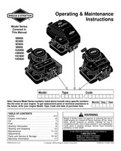
Briggs & Stratton 10A900 Series Operating & Maintenance Instructions (21 pages)
Brand: Briggs & Stratton
|
Category: Engine
|
Size: 0.5 MB
Table of Contents
-
Hazard Symbols and Meanings
3
-
Engine Parts
6
-
Tune-Up Specifications
6
-
Oil Capacity
7
-
Checking and Adding Oil
7
-
Adding Fuel
8
-
Starting and Stopping
10
-
To Start Engine
10
-
To Stop Engine
10
-
Maintenance
11
-
Emission Control
11
-
Changing Oil
11
-
Air Cleaner
12
-
Throttle Adjustment
14
-
Carburetor Adjustment
14
-
Service & Storage
15
Advertisement
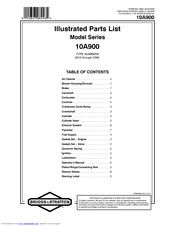
Briggs & Stratton 10A900 Series Illustrated Parts List (16 pages)
Snapper Air Cleaner Parts List
Brand: Briggs & Stratton
|
Category: Engine
|
Size: 0.66 MB
Advertisement
Related Products
-
Briggs & Stratton 100000 650 Series
-
Briggs & Stratton 100000 675 Series
-
Briggs & Stratton 100000 Q 550 Series
-
Briggs & Stratton 100000 LX 500 Series
-
Briggs & Stratton 100000 Q550 series
-
Briggs & Stratton Vanguard 10V000
-
Briggs & Stratton 1000000
-
Briggs & Stratton 10B900
-
Briggs & Stratton 10C900
-
Briggs & Stratton 10D900
Briggs & Stratton Categories
Engine
Portable Generator
Pressure Washer
![]()
Lawn Mower
Inverter
More Briggs & Stratton Manuals
Краткое содержание страницы № 8
21B900 521 187 187A 601 601 240A 1054 240 356 187B 387 385A 356A 527 387A 788 387A 601 356B 385 527A 385 187C 356C 601 729 972 187B 957 789 601 187D 789A 601 789B 958 670 918 601 729 601A 334 333 851 203 920 205 616 227 404 614 505 621 507 520 359 373 562 188 222 268 269 270 216 209 271 265 216A 559 267 559A 202 232 Illustrations cover a range of engines. Parts shown without corresponding text may not be used on your specific engine. 5036—8 Assemblies include all parts shown in frames. 03/23/20
Краткое содержание страницы № 9
21B900 DUAL TRI 10 — 16AMP DC ONLY CIRCUIT CIRCUIT 474A 1059 474B 1059 474C 1059 474D 1059 877A 877B 877C 877 578 578 578 878 526A 526A 526B 526B 501B 501D 501C 501A NOTE: All stators use a No. 1119mounting screw. NOTE: Theproperflywheelpartnumberand/orthealternatormagnetsizewill determine the alternator type oroutput. Seerepair instructionmanual for additional information. Illustrations cover a range of engines. Parts shown without corresponding text may not be used on your specific engine. 50
Краткое содержание страницы № 10
21B900 REF. PART REF. PART REF. PART NO. NO. DESCRIPTION NO. NO. DESCRIPTION NO. NO. DESCRIPTION 1 697377 Cylinder Assembly 5 796183 Head—Cylinder 23A 693555 Flywheel 2 399265 Kit—Bushing/Seal 7 273280S Gasket—Cylinder Head (Rewind Starter) (Magneto Side) 9 697109 Gasket—Breather Used on Type No(s). 3 391086S Seal—Oil 0015, 0016, 0117, (Used Before Code (Magneto Side) 0142. Date 07071900). 4 697106 Sump—Engine ———— Note ———— (After Date Code Use (Used After Code Date 698283
Краткое содержание страницы № 11
21B900 REF. PART REF. PART REF. PART NO. NO. DESCRIPTION NO. NO. DESCRIPTION NO. NO. DESCRIPTION 37 697352 Guard—Flywheel 78 691003 Screw 117 796079 Jet—Main 37A 697626 Guard—Flywheel (Flywheel Guard) (Standard)(Nikki) (Electric Start) 78A 690364 Screw Used on Type No(s). Used on Type No(s). (Flywheel Guard) 0205, 0206. 0015, 0016, 0020, (Electric Start) ———— Note ———— 0022, 0114, 0116, Used on Type No(s). 796079 Jet—Main 0117, 0121, 0142, 0015, 0016, 0020, (Standard)(Nikki)
Краткое содержание страницы № 12
21B900 REF. PART REF. PART REF. PART NO. NO. DESCRIPTION NO. NO. DESCRIPTION NO. NO. DESCRIPTION 794352 Jet—Main 699897 Jet—Main 0136, 0137, 0139, (Standard)(Nikki) (Standard)(Nikki) 0146, 0147, 0149, 0153, 0155, 0159, (Used Before Code (Used Before Code Date 08121500 and Date 07011500). 0163, 0164, 0183, After Code Date Used on Type No(s). 0190, 0192, 0193, 07030400). 0020, 0110, 0114, 0195, 0198, 0203. Used on Type No(s). 0116, 0117, 0119, 791405 Jet—Main 0015E1, 0016E1, 0120, 0121, 0123, (
Краткое содержание страницы № 13
21B900 REF. PART REF. PART REF. PART NO. NO. DESCRIPTION NO. NO. DESCRIPTION NO. NO. DESCRIPTION 791405 Jet—Main 125A 796078 Carburetor 794653 Carburetor (High Altitude)(Nikki) (Nikki With Solenoid) (Nikki Without Solenoid) (Used Before Code Used on Type No(s). Date 08121500 and 0205, 0206. (Used Before Code After Code Date ———— Note ———— Date 08121500 and 07011400). 796077 Carburetor After Code Date Used on Type No(s). (Nikki Without 07030400). 0020, 0117, 0124, Solenoid) Used
Краткое содержание страницы № 14
21B900 REF. PART REF. PART REF. PART NO. NO. DESCRIPTION NO. NO. DESCRIPTION NO. NO. DESCRIPTION 791266 Carburetor 137 281165S Gasket—Float Bowl 202 691841 Link—Mechanical (Nikki Without (Walbro) Governor Solenoid) 137A 698781 Gasket—Float Bowl 203 691381 Crank—Bell (Used Before Code Used on Type No(s). (Nikki) Date 07011500). 0020, 0028. 141 790902 Kit—Choke Shaft Used on Type No(s). 205 691693 Screw (Walbro) 0020, 0110, 0114, (Bell Crank) 141A 698778 Kit—Choke Shaft 0116, 0117, 0119, 209
Краткое содержание страницы № 15
21B900 REF. PART REF. PART REF. PART NO. NO. DESCRIPTION NO. NO. DESCRIPTION NO. NO. DESCRIPTION 240 298090S Filter—Fuel 300A 796001 Muffler 311 497608 Brush Set (Red, 150 Microns) (Used After Code Date 333 795315 Armature—Magneto Used on Type No(s). 08071300). 334 691061 Screw 0110. Used on Type No(s). (Magneto Armature) ———— Note ———— 0110, 0116, 0120, 337 491055S Plug—Spark 394358Ss Filter—Fuel 0123, 0124, 0138, ———— Note ———— (White, 75 Microns) 0141, 0146
Краткое содержание страницы № 16
21B900 REF. PART REF. PART REF. PART NO. NO. DESCRIPTION NO. NO. DESCRIPTION NO. NO. DESCRIPTION 431 697122 Elbow—Intake 501A 794360 Regulator 525 697184 Tube—Dipstick (5 To 9 Amp Used on Type No(s). 445 698413 Filter—Air Cleaner Regulated) 0110, 0114, 0116, Cartridge 0120, 0121, 0123, Used on Type No(s). (Non Washable) 0110, 0119, 0123, 0126, 0130, 0136, 455 695113 Cup—Flywheel 0127, 0130, 0136, 0137, 0139, 0146, Used on Type No(s). 0155, 0156, 0195, 0147, 0149, 0153, 0015, 0016, 0020, 0155
Краткое содержание страницы № 17
21B900 REF. PART REF. PART REF. PART NO. NO. DESCRIPTION NO. NO. DESCRIPTION NO. NO. DESCRIPTION 562 691119 Bolt 614 691620 Pin—Cotter 757 697607 Link—Counterweight (Governor Control 616 692012 Crank—Governor 758 697391 Counterweight Lever) 617 692138 Seal—O Ring (Used After Code Date 563 695449 Screw (Intake Manifold) 05100200). (Debris Screen Guard) 621 692310 Switch—Stop ———— Note ———— 578 692306 Wire Assembly Used on Type No(s). 795940 Counterweight 579 691029 Nut 0119,
Краткое содержание страницы № 18
21B900 REF. PART REF. PART REF. PART NO. NO. DESCRIPTION NO. NO. DESCRIPTION NO. NO. DESCRIPTION 847 790442 Dipstick/Tube 878 398661 Harness—Alternator 977 690192 Gasket Set—Carburetor Assembly 883 692236 Gasket—Exhaust (Walbro) Used on Type No(s). 914 691108 Screw 987 691326 Seal—Throttle Shaft 0110, 0114, 0116, (Rocker Cover) 987A 698777 Seal—Throttle Shaft 0120, 0121, 0123, 918 791851 Hose—Vacuum 1005 796082 Fan—Flywheel 0126, 0130, 0136, (Molded) (Used After Code Date 0137, 0139, 0146
Краткое содержание страницы № 19
21B900 REF. PART REF. PART REF. PART NO. NO. DESCRIPTION NO. NO. DESCRIPTION NO. NO. DESCRIPTION 1051 691265 Ring—Retaining 1090 691293 Retainer—Brush 1266A 697123 Seal—O Ring 1054 280275 Tie—Cable 1091 691333 Cap—Limiter (Intake Elbow) 1058 276344 Operator’s Manual 1095 691581 Gasket Set—Valve 1267 697419 Latch—Blower Housing 1059 698516 Kit—Screw/Washer 1119 691183 Screw (Black) 1070 690372 Screw (Alternator) ———— Note ———— (Flywheel Fan) 1127 695407 Screw 697424 Latch-
Краткое содержание страницы № 20
Not for Reproduction
Краткое содержание страницы № 1
FORM MS—5036—03/23/2009
REPLACES FORM MS—5036—06/18/2008
FILE IN SECT. 2 OF SERVICE MANUAL
21B900
IllustratedPartsList
ModelSeries
21B900
TYPE NUMBERS
0015 through 0206.
TABLEOFCONTENTS
AirCleaner ……………………. 6
Alternator …………………….. 9
BlowerHousing………………… 6
Camshaft ……………………… 3
Carburetor…………………….. 5
Controls ………………………. 8
Crankshaft…………………….. 3
Cylinder ……………………….
Краткое содержание страницы № 2
21B900 1319 WARNING LABEL 1058 OPERATOR’S MANUAL REQUIREDwhenreplacingparts with warning labels affixed. 1 2 11 10 584 850 9 1264 1263 552 691 718 4 4A 306 1017 12 12 307 22 15 20 20 415 1027 1024A 239 965 943 750 Illustrations cover a range of engines. Parts shown without corresponding text may not be used on your specific engine. 5036—2 Assemblies include all parts shown in frames. 03/23/2009 2 Not for Reproduction
Краткое содержание страницы № 3
21B900 25 27 26 28 27 29 847 32 523 842 16 46 24 525 45 146 357 524 741 43 758 1270 759 757 Illustrations cover a range of engines. Parts shown without corresponding text may not be used on your specific engine. 5036—3 Assemblies include all parts shown in frames. 03/23/2009 3 Not for Reproduction
Краткое содержание страницы № 4
21B900 45 13 1026 5 34 42 868 36 238 33 42 42 337 7 883 635 35 383 1022 1034 51 617 830 1029 850 51A 192 1022 914 654 50 186 1023 14 53 51A 51 415 705 617 54 358 ENGINE GASKETSET 1095 VALVE GASKETSET 1022 7 1022 51 7 12 51A 3 943 883 868 868 524 9 51 617 1266 883 691 51A 1266A 842 20 Illustrations cover a range of engines. Parts shown without corresponding text may not be used on your specific engine. 5036—4 Assemblies include all parts shown in frames. 03/23/2009 4 Not for Reproduction
Краткое содержание страницы № 5
21B900 125A 141A 141 NIKKI 131 131A 217 108A 130A 130 634A 95A 634 95 108 987A 98A 987 118 93 117 98 94A 1091 51 94 51 105A 127A 133A 104A 143 1091 142 135A LMT/ PART 127 NUMBER 106 137A LOCATIONS 105 975A 133 104 137A 975 1127 137 947A 141C 276A 276 652 WALBRO 950 This Illustration Represents Several Carburetors. Parts Shown May Not Be Included In All Kits. 121 CARBURETOR OVERHAULKIT 121ACARBURETOR OVERHAULKIT 137A 137A 137A 137A 51 98A 987 51 137 104 1266 105 1266A 95A 1266 617 142 987A 93 106
Краткое содержание страницы № 6
21B900 1036 EMISSIONS LABEL 304 1139 1040A 773 305A 643 967 305 445 1040 1267 187D 187A 601 601 968 431 1266A 1266 676 676A 677 677 300B 300A 883 883 613A 613B 864 864 883 883 81 613 613 81 823 Illustrations cover a range of engines. Parts shown without corresponding text may not be used on your specific engine. 5036—6 Assemblies include all parts shown in frames. 03/23/2009 6 Not for Reproduction
Краткое содержание страницы № 7
21B900 73A 949 415A 1005A 493 563 75 74 1070A 78 73 1005 37 1044 1070 455 1005B 363 23 1051 783 23A 78A 37A 729B 608 65 729A 697 55 309 801 58 1051 57 60 510 56 783 310 513 459 689 1090 311 456 579 797 597 802 Illustrations cover a range of engines. Parts shown without corresponding text may not be used on your specific engine. 5036—7 Assemblies include all parts shown in frames. 03/23/2009 7 Not for Reproduction