Краткое содержание страницы № 1
SERVICE
MANUAL
REVISION 0
FY8-13FB-000
AUG. 1998
COPYRIGHT © 1998 CANON INC. CANON NP7161/NP7160 REV.0 AUG. 1998 PRINTED IN JAPAN (IMPRIME AU JAPON)
Краткое содержание страницы № 2
IMPORTANT THIS DOCUMENTATION IS PUBLISHED BY CANON INC., JAPAN, TO SERVE AS A SOURCE OF REFERENCE FOR WORK IN THE FIELD. SPECIFICATIONS AND OTHER INFORMATION CONTAINED HEREIN MAY VARY SLIGHTLY FROM ACTUAL MACHINE VALUES OR THOSE FOUND IN ADVERTISING AND OTHER PRINTED MATTER. ANY QUESTIONS REGARDING INFORMATION CONTAINED HEREIN SHOULD BE DIRECTED TO THE COPIER SERVICE DEPARTMENT OF THE SALES COMPANY. THIS DOCUMENTATION IS INTENDED FOR ALL SALES AREAS, AND MAY CONTAIN INFORMATION NOT APPLICABLE TO
Краткое содержание страницы № 3
Краткое содержание страницы № 4
Краткое содержание страницы № 5
INTRODUCTION This Service Manual contains basic facts and figures on the NP7161/NP7160 needed to service the machine in the field. This copier is designed to enable full automatic copying work, and comes with the following systems accessories: 1. ADF-G1* 2. Staper Sorter-L1* 3. MS-C1* 4. Cassette Feeding Module-C1 * NP7161 only. This Service Manual covers the copier only, and consists of the following chapters: Chapter 1 General Description introduces the copier’s features and specifications, sh
Краткое содержание страницы № 6
The following rules apply throughout this Service Manual: 1. Each chapter contains sections explaining the purpose of specific functions and the relationship between electrical and mechanical systems with reference to the timing of operation. In the diagrams, represents the path of mechanical drive—where a signal name accompanies the symbol , the arrow indicates the direction of the electric signal. The expression “turn on the power” means flipping on the power switch, closing the front door
Краткое содержание страницы № 7
System Configuration The copier is designed to accommodate the following accessories: *NP7161 only. ADF-G1* Feeds a stack of original pages to the copyboard page by page. Control Card IV N Controls volumes MS-C1* Stapler Sorter-L1* of copying work. Sorts and groups up to In addition to the functions 10 sets of pages of a 10-bin sorter, staples automatically. sorted pages automatically. Cassette Feeding Module-C1 Provides an additional cassette. COPYRIGHT © 1998 CANON INC. CANON NP7161/NP716
Краткое содержание страницы № 8
iv COPYRIGHT © 1998 CANON INC. CANON NP7161/NP7160 REV.0 AUG. 1998 PRINTED IN JAPAN (IMPRIME AU JAPON)
Краткое содержание страницы № 9
CONTENTS CHAPTER 1 GENERAL DESCRIPTION I. FEATURES ………………………………………. 1-1 IV. OPERATING THE MACHINE ……………. 1-10 II. SPECIFICATIONS …………………………….. 1-2 A. Control Panel……………………………… 1-10 A. Copier …………………………………………. 1-2 B. User Mode …………………………………. 1-12 1. Type ……………………………………… 1-2 1. Outline ………………………………….
Краткое содержание страницы № 10
CHAPTER 3 EXPOSURE SYSTEM I. OUTLINE OF OPERATION ………………… 3-1 1. Outline …………………………………. 3-10 A. Changing the Reproduction Ratio…… 3-1 2. Detection of the Original Size II. LENS DRIVE SYSTEM ………………………. 3-3 by the ADF …………………………… 3-10 A. Driving the Lens …………………………… 3-3 V. DISASSEMBLY/ASSEMBLY …………….. 3-11 1. Outline …………………………………… 3-3 A. Scanner Drive As
Краткое содержание страницы № 11
1. Removing the Drum Unit ……….. 4-28 1. Outline …………………………………. 4-32 2. Cleaning the Photosensitive 2. Stringing the Charging Wires ….. 4-32 Drum ……………………………………. 4-29 3. Adjusting the Height of the Charging Wires …………………….. 4-36 3. Removing the Cleaner G. Developing Assembly………………….. 4-37 Thermistor ……………………………. 4-29 1. Removing the Developing D. Primary Charging Assembly …………
Краткое содержание страницы № 12
CHAPTER 6 FIXING SYSTEM I. OUTLINE OF OPERATION ………………… 6-1 6. Removing the Main Thermistor … 6-12 A. Outline ………………………………………… 6-1 7. Removing the Sub Thermistor … 6-12 B. Controlling the Fixing Temperature … 6-2 8. Removing the Fixing Upper Roller …………………………………… 6-13 C. Error Detection Circuit …………………… 6-5 9. Removing the Fixing Lower 1. Outline …………………………………… 6-5 Roller
Краткое содержание страницы № 13
CHAPTER 8 INSTALLATION I. SELECTING THE SITE………………………. 8-1 IV. INSTALLING THE CONTROL II. UNPACKING AND INSTALLATION …….. 8-2 CARD IV N ……………………………………… 8-13 A. Unpacking …………………………………… 8-2 V. INSTALLING THE REMOTE DIAGNOSTIC DEVICE II …………………….. 8-14 B. Removing the Metal Fixings…………… 8-3 C. Mounting the Drum Unit ………………… 8-4 VI. INSTALLING THE ACCESSORY D. Cleaning the Parts
Краткое содержание страницы № 14
B. Image Fault Samples ………………… 10-28 17. E800 ………………………………….. 10-51 C. Troubleshooting Image Faults ……. 10-29 18. E805 ………………………………….. 10-51 1. The copy is too light. 19. E821 ………………………………….. 10-51 (halftone area only) ……………… 10-29 20. AC power is absent. …………….. 10-52 2. The copy is too light. 21. DC power supply is absent. ….. 10-53 (including solid black area) …… 10-30 2
Краткое содержание страницы № 15
1. DC Controller PCB ………………. 10-77 D. Display Mode [1] ………………………. 10-84 2. Power Supply PCB ……………… 10-80 E. I/O Display Mode [2]………………….. 10-88 3. Lamp Regulator PCB …………… 10-80 F. Adjust Mode [3] ………………………… 10-92 4. High-Voltage Power Supply G. Function Mode [4] …………………….. 10-94 PCB …………………………………… 10-81 H. Option Mode [5] ………………………… 10-95 VII. SER
Краткое содержание страницы № 16
Краткое содержание страницы № 17
CHAPTER 1 GENERAL DESCRIPTION This chapter introduces the copier’s features and specifications, shows how to operate the copier, and explains how copies are made. I. FEATURES ………………………………………. 1-1 A. Control Panel……………………………… 1-10 II. SPECIFICATIONS …………………………….. 1-2 B. User Mode …………………………………. 1-12 A. Copier …………………………………………. 1-2 V. ROUTINE MAINTENANCE III. NAMES
Краткое содержание страницы № 18
Краткое содержание страницы № 19
CHAPTER 1 GENERAL DESCRIPTION I. FEATURES 1. The copier is designed light in weight (about 42 kg), and compact in size (566 mm wide, 541mm deep). 2. The copier turns out as many as 16 copies each minute (A4/LTR). 3. The addition of the Cassette Feeding Module-C1 (accessory) enables a source of paper capable of holding a maximum of 1,050 sheets. 4. The density may be adjusted to 33 different shades, or in automatic mode (AE). 5. The use of a photo mode promises faithful reproduction of halftone
Краткое содержание страницы № 20
CHAPTER 1 GENERAL DESCRIPTION II. SPECIFICATIONS A. Copier 1. Type Body Desktop Copyboard Fixed Light source Halogen lamp (120V:200W/230V:220W) Lens Lens array Photosensitive material OPC (30 dia.) 2. Mechanisms Copying Indirect electrostatic Charging Corona Exposure Slit (moving light source) Copy density adjustment Auto or manual Development Dry (toner projection) Auto Front cassette (1 pc.) Pick-up 2 Manual Multifeeder (5 mm deep approx.; about 50 sheets of 8
-
Страница 1
COPYRIGHT © 1998 CANON INC. CANON NP7161/NP7160 REV.0 AUG. 1998 PRINTED IN JAPAN (IMPRIME AU JAPON) FY8-13FB-000 AUG. 1998 SERVICE MANUAL REVISION 0[…]
-
Страница 2
COPYRIGHT © 1998 CANON INC. CANON NP7161/NP7160 REV.0 AUG. 1998 PRINTED IN JAPAN (IMPRIME AU JAPON) IMPORTANT THIS DOCUMENTATION IS PUBLISHED BY CANON INC., JAPAN, TO SERVE AS A SOURCE OF REFERENCE FOR WORK IN THE FIELD. SPECIFICATIONS AND OTHER INFORMATION CONTAINED HEREIN MAY VARY SLIGHTLY FROM ACTUAL MACHINE VALUES OR THOSE FOUND IN ADVERTISING[…]
-
Страница 3
[…]
-
Страница 4
[…]
-
Страница 5
COPYRIGHT © 1998 CANON INC. CANON NP7161/NP7160 REV.0 AUG. 1998 PRINTED IN JAPAN (IMPRIME AU JAPON) i INTR ODUCTION This Service Manual contains basic facts and figures on the NP7161/NP7160 needed to service the machine in the field. This copier is designed to enable full automatic copying work, and comes with the following systems accessories: 1.[…]
-
Страница 6
COPYRIGHT © 1998 CANON INC. CANON NP7161/NP7160 REV.0 AUG. 1998 PRINTED IN JAPAN (IMPRIME AU JAPON) ii The following rules apply throughout this Service Manual: 1. Each chapter contains sections explaining the purpose of specific functions and the relationship between electrical and mechanical systems with reference to the timing of operation. In […]
-
Страница 7
COPYRIGHT © 1998 CANON INC. CANON NP7161/NP7160 REV.0 AUG. 1998 PRINTED IN JAPAN (IMPRIME AU JAPON) iii System Configuration The copier is designed to accommodate the following accessories: *NP7161 only. ADF-G1* Control Card IV N Feeds a stack of original pages to the copyboard page by page. Stapler Sorter-L1* In addition to the functions of a 10-[…]
-
Страница 8
COPYRIGHT © 1998 CANON INC. CANON NP7161/NP7160 REV.0 AUG. 1998 PRINTED IN JAPAN (IMPRIME AU JAPON) iv[…]
-
Страница 9
COPYRIGHT © 1998 CANON INC. CANON NP7161/NP7160 REV.0 AUG. 1998 PRINTED IN JAPAN (IMPRIME AU JAPON) v CONTENTS CHAPTER 1 GENERAL DESCRIPTION I. FEATURES ………………………………………. 1-1 II. SPECIFICATIONS …………………………….. 1-2 A. Copier …………………………………………. 1-2 1. Type …………..[…]
-
Страница 10
COPYRIGHT © 1998 CANON INC. CANON NP7161/NP7160 REV.0 AUG. 1998 PRINTED IN JAPAN (IMPRIME AU JAPON) vi CHAPTER 3 EXPOSURE SYSTEM I. OUTLINE OF OPERATION ………………… 3-1 A. Changing the Reproduction Ratio …… 3-1 II. LENS DRIVE SYSTEM ………………………. 3-3 A. Driving the Lens …………………………… 3-3 1. Outline […]
-
Страница 11
COPYRIGHT © 1998 CANON INC. CANON NP7161/NP7160 REV.0 AUG. 1998 PRINTED IN JAPAN (IMPRIME AU JAPON) vii 1. Removing the Drum Unit ……….. 4-28 2. Cleaning the Photosensitive Drum ……………………………………. 4-29 3. Removing the Cleaner Thermistor ……………………………. 4-29 D. Primary Charging Assembly ………… […]
-
Страница 12
COPYRIGHT © 1998 CANON INC. CANON NP7161/NP7160 REV.0 AUG. 1998 PRINTED IN JAPAN (IMPRIME AU JAPON) viii CHAPTER 6 FIXING SYSTEM I. OUTLINE OF OPERATION ………………… 6-1 A. Outline ………………………………………… 6-1 B. Controlling the Fixing Temperature … 6-2 C. Error Detection Circuit …………………… 6-5 1. O[…]
-
Страница 13
COPYRIGHT © 1998 CANON INC. CANON NP7161/NP7160 REV.0 AUG. 1998 PRINTED IN JAPAN (IMPRIME AU JAPON) ix CHAPTER 8 INSTALLATION I. SELECTING THE SITE ………………………. 8-1 II. UNPACKING AND INSTALLATION …….. 8-2 A. Unpacking …………………………………… 8-2 B. Removing the Metal Fixings …………… 8-3 C. Mounting th[…]
-
Страница 14
COPYRIGHT © 1998 CANON INC. CANON NP7161/NP7160 REV.0 AUG. 1998 PRINTED IN JAPAN (IMPRIME AU JAPON) x B. Image Fault Samples ………………… 10-28 C. Troubleshooting Image Faults ……. 10-29 1. The copy is too light. (halftone area only) ……………… 10-29 2. The copy is too light. (including solid black area) …… 10-30 3. The cop[…]
-
Страница 15
COPYRIGHT © 1998 CANON INC. CANON NP7161/NP7160 REV.0 AUG. 1998 PRINTED IN JAPAN (IMPRIME AU JAPON) xi 1. DC Controller PCB ………………. 10-77 2. Power Supply PCB ……………… 10-80 3. Lamp Regulator PCB …………… 10-80 4. High-Voltage Power Supply PCB …………………………………… 10-81 VII. SERVICE MODE ……….[…]
-
Страница 16
[…]
-
Страница 17
COPYRIGHT © 1998 CANON INC. CANON NP7161/NP7160 REV.0 AUG. 1998 PRINTED IN JAPAN (IMPRIME AU JAPON) I. FEATURES ………………………………………. 1-1 II. SPECIFICATIONS …………………………….. 1-2 A. Copier …………………………………………. 1-2 III. NAMES OF PARTS ……………………………. 1-8 A. E[…]
-
Страница 18
[…]
-
Страница 19
COPYRIGHT © 1998 CANON INC. CANON NP7160/NP7161 REV.0 AUG. 1998 PRINTED IN JAPAN (IMPRIME AU JAPON) 1–1 CHAPTER 1 GENERAL DESCRIPTION I. FEA TURES 1. The copier is designed light in weight (about 42 kg), and compact in size (566 mm wide, 541mm deep). 2. The copier turns out as many as 16 copies each minute (A4/LTR). 3. The addition of the Casset[…]
-
Страница 20
1–2 COPYRIGHT © 1998 CANON INC. CANON NP7160/NP7161 REV.0 AUG. 1998 PRINTED IN JAPAN (IMPRIME AU JAPON) CHAPTER 1 GENERAL DESCRIPTION II. SPECIFICA TIONS A. Copier 1. Type 2. Mechanisms Body Copyboard Light source Lens Photosensitive material Desktop Fixed Halogen lamp (120V:200W/230V:220W) Lens array OPC (30 dia.) Copying Charging Exposure Copy[…]
-
Страница 21
COPYRIGHT © 1998 CANON INC. CANON NP7160/NP7161 REV.0 AUG. 1998 PRINTED IN JAPAN (IMPRIME AU JAPON) 1–3 CHAPTER 1 GENERAL DESCRIPTION 3. Performance Original type Maximum original size Direct Reduce I Reduce II Reduce III Reduce IV Enlarge I Enlarge II Enlarge III Enlarge IV Zoom Wait time First copy Continuous copying Copy size Cassette Multife[…]
-
Страница 22
1–4 COPYRIGHT © 1998 CANON INC. CANON NP7160/NP7161 REV.0 AUG. 1998 PRINTED IN JAPAN (IMPRIME AU JAPON) CHAPTER 1 GENERAL DESCRIPTION Claws Frame Copy tray Leading edge Trailing edge Left/right Auto clear Auto power-off Auto pre-heat Accessories Used 55 mm deep (500 sheets of 80 g/m 2 paper; 250 sheets if B5) 100 sheets approx. (plain paper ; 64[…]
-
Страница 23
COPYRIGHT © 1998 CANON INC. CANON NP7160/NP7161 REV.0 AUG. 1998 PRINTED IN JAPAN (IMPRIME AU JAPON) 1–5 CHAPTER 1 GENERAL DESCRIPTION 4. Others Specifications subject to change without notice. Temperature Humidity Atmospheric pressure 120V 120V (UL) 127V 230V Maximum Standby Continuous Copying Standby Ozone (8-hr average) Width Depth Height Copy[…]
-
Страница 24
1–6 COPYRIGHT © 1998 CANON INC. CANON NP7160/NP7161 REV.0 AUG. 1998 PRINTED IN JAPAN (IMPRIME AU JAPON) CHAPTER 1 GENERAL DESCRIPTION Size A3 (297 × 420mm) A4 (210 × 297mm) B4 (257 × 364mm) B5 (182 × 257mm) A4R (297 × 210mm) B5R (257 × 182mm) A3 → A4R B4 → B5R B4 → A4R A3 → B4 A4 → B5 A5R → A3 A4R → A3 B5R → B4 A4R → B4 B[…]
-
Страница 25
COPYRIGHT © 1998 CANON INC. CANON NP7160/NP7161 REV.0 AUG. 1998 PRINTED IN JAPAN (IMPRIME AU JAPON) 1–7 CHAPTER 1 GENERAL DESCRIPTION Size 11″ × 17″ (279 × 432mm) LTR (297 × 216mm) LGL (216 × 356mm) LTRR (216 × 297mm) Reproduction mode Copy paper 11″ × 17″ LTR LGL LTRR LTRR LGL LTRR 11″ × 17″ 11″ × 17&q[…]
-
Страница 26
1–8 COPYRIGHT © 1998 CANON INC. CANON NP7160/NP7161 REV.0 AUG. 1998 PRINTED IN JAPAN (IMPRIME AU JAPON) CHAPTER 1 GENERAL DESCRIPTION III. NAMES OF PARTS A. External Vie w Figure 1-301 Figure 1-302 [4] Lower delivery cover [5] Front fixing cover [6] Inside cover [7] Open/close lever [8] Lower inside cover [9] Static eliminator [1] Copy tray [2] […]
-
Страница 27
COPYRIGHT © 1998 CANON INC. CANON NP7160/NP7161 REV.0 AUG. 1998 PRINTED IN JAPAN (IMPRIME AU JAPON) 1–9 CHAPTER 1 GENERAL DESCRIPTION B. Cr oss Section 1. Copier [1] [2] [3] [4] [5] [6] [10] [11] [13] [7] [8] [9] [14] [12] [15] [16] [17] [19] [24] [25] [26] [20] [21] [22] [23] [18] [21] Transfer charging assembly [22] Separation static eliminato[…]
-
Страница 28
1–10 COPYRIGHT © 1998 CANON INC. CANON NP7160/NP7161 REV.0 AUG. 1998 PRINTED IN JAPAN (IMPRIME AU JAPON) CHAPTER 1 GENERAL DESCRIPTION IV . OPERA TING THE MA CHINE A. Contr ol P anel ID 2 3 1 5 6 4 8 9 7 0 C Reset Additional Functions Interrupt Clear Start Stop Energy Saver Auto Zoom % Zoom Paper Select Auto Paper A3/1117 A4/LTR A4/LTR B4/LGL B5[…]
-
Страница 29
COPYRIGHT © 1998 CANON INC. CANON NP7160/NP7161 REV.0 AUG. 1998 PRINTED IN JAPAN (IMPRIME AU JAPON) 1–11 CHAPTER 1 GENERAL DESCRIPTION Ref. Name [15] [16] [17] [18] [19] [20] [21] [22] [23] [24] [25] [26] [27] [28] * Applies to the NP7161 only Description Remarks [10] [11] [12] [13] [14] *Requires an ADF. *Requires an ADF. Flashes when the waste[…]
-
Страница 30
1–12 COPYRIGHT © 1998 CANON INC. CANON NP7160/NP7161 REV.0 AUG. 1998 PRINTED IN JAPAN (IMPRIME AU JAPON) CHAPTER 1 GENERAL DESCRIPTION B. User Mode 1. Outline The copier provides user modes, which may be changed freely by the user. These modes provide the functions shown in the following table. Notation Resetting user mode Changing auto clear ti[…]
-
Страница 31
COPYRIGHT © 1998 CANON INC. CANON NP7160/NP7161 REV.0 AUG. 1998 PRINTED IN JAPAN (IMPRIME AU JAPON) 1–13 CHAPTER 1 GENERAL DESCRIPTION Changing Page Fit mode (ratio) Changing Page Fit mode (centering) Changing Page Fit mode (non-image width) Correcting density Setting special paper mode Drum cleaning mode 93% ON OFF 0 0 OFF U09 U10 U11 U12 U13 U[…]
-
Страница 32
1–14 COPYRIGHT © 1998 CANON INC. CANON NP7160/NP7161 REV.0 AUG. 1998 PRINTED IN JAPAN (IMPRIME AU JAPON) CHAPTER 1 GENERAL DESCRIPTION V . ROUTINE MAINTENANCE (BY THE USER) Instruct the user to clean the following parts at least once a week. 1. Copyboard Glass Wipe with a moist cloth (moistened with water or mild detergent solution); then, dry w[…]
-
Страница 33
COPYRIGHT © 1998 CANON INC. CANON NP7160/NP7161 REV.0 AUG. 1998 PRINTED IN JAPAN (IMPRIME AU JAPON) 1–15 CHAPTER 1 GENERAL DESCRIPTION VI. POINTS T O NO TE (BY THE USER) • Toner Cartridge Instruct the user to dispose of any used (empty) toner cartridge according to governmental guidelines. • Waste Toner Box Instruct the user to keep any wast[…]
-
Страница 34
1–16 COPYRIGHT © 1998 CANON INC. CANON NP7160/NP7161 REV.0 AUG. 1998 PRINTED IN JAPAN (IMPRIME AU JAPON) CHAPTER 1 GENERAL DESCRIPTION VII. IMA GE FORMA TION A. Outline The copier is constructed as shown in Figure 1-701. Copyboard glass Scanning lamp Lens Pre-exposure lamp Fixing assembly Primary charging assembly Blanking exposure lamp Static e[…]
-
Страница 35
COPYRIGHT © 1998 CANON INC. CANON NP7160/NP7161 REV.0 AUG. 1998 PRINTED IN JAPAN (IMPRIME AU JAPON) 1–17 CHAPTER 1 GENERAL DESCRIPTION The copier’s image formation processes consist of the following eight steps: Step 1 Pre-exposure Step 2 Primary charging (negative DC) Step 3 Image exposure Step 4 Development (AC + negative DC) Step 5 Trans[…]
-
Страница 36
[…]
-
Страница 37
COPYRIGHT © 1998 CANON INC. CANON NP7161/NP7160 REV.0 AUG. 1998 PRINTED IN JAPAN (IMPRIME AU JAPON) CHAPTER 2 BASIC OPERATION I. BASIC MECHANISMS ……………………….. 2-1 A. Functional Construction ………………… 2-1 B. Outline of the Electrical Circuitry …….. 2-2 C. Basic Sequence of Operations ………. 2-4 D. Main Motor (M1[…]
-
Страница 38
[…]
-
Страница 39
COPYRIGHT © 1998 CANON INC. CANON NP7161/NP7160 REV.0 AUG. 1998 PRINTED IN JAPAN (IMPRIME AU JAPON) 2–1 CHAPTER 2 BASIC OPERATION I. BASIC MECHANISMS A. Functional Construction The copier can broadly be divided into the following four functional blocks: pick-up, feeding, exposure, image formation, and control. Figure 2-101 Control system Copyboa[…]
-
Страница 40
2–2 COPYRIGHT © 1998 CANON INC. CANON NP7161/NP7160 REV.0 AUG. 1998 PRINTED IN JAPAN (IMPRIME AU JAPON) CHAPTER 2 BASIC OPERATION B. Outline of the Electrical Cir cuitr y The copier’s major electrical mechanisms are controlled by the microprocessor on the DC controller PCB. The ICs on the DC controller PCB are shown below. IC121 (ROM) • C[…]
-
Страница 41
COPYRIGHT © 1998 CANON INC. CANON NP7161/NP7160 REV.0 AUG. 1998 PRINTED IN JAPAN (IMPRIME AU JAPON) 2–3 CHAPTER 2 BASIC OPERATION Figure 2-102 <Control> <Loads> <Sensors> Sensors Switches Toner sensor AE sensor Control panel Thermistors DC controller PCB IC119 (CPU) Cassette relay PCB Motors Fans Clutches Solenoids Counter LEDs[…]
-
Страница 42
2–4 COPYRIGHT © 1998 CANON INC. CANON NP7161/NP7160 REV.0 AUG. 1998 PRINTED IN JAPAN (IMPRIME AU JAPON) CHAPTER 2 BASIC OPERATION C. Basic Sequence of Operations 1. Basic Sequence of Operations at Power-On Figure 2-103 Power switch ON 160 ° C 120 ° C Wait indicator WMUP WMUPR (flashing) Green STBY Sequence Scanner motor (M2) Scanner home posit[…]
-
Страница 43
COPYRIGHT © 1998 CANON INC. CANON NP7161/NP7160 REV.0 AUG. 1998 PRINTED IN JAPAN (IMPRIME AU JAPON) 2–5 CHAPTER 2 BASIC OPERATION WMUP (warm-up) From when the power switch is turned on until the surface temperature of the upper fixing roller reaches 120˚C. Waits until the upper fixing roller warms up. Moves the lens, mirror, and scanner to home[…]
-
Страница 44
2–6 COPYRIGHT © 1998 CANON INC. CANON NP7161/NP7160 REV.0 AUG. 1998 PRINTED IN JAPAN (IMPRIME AU JAPON) CHAPTER 2 BASIC OPERATION 2. Basic Sequence of Operations at Copy Start Figure 2-104 Start key ON Wait indicator STBY Green Orange FW RV STBY LSTR SCRV SCFW SCRV SCFW INTR AER Sequence Scanner motor (M2) Scanner home position sensor (PS1) Fixi[…]
-
Страница 45
COPYRIGHT © 1998 CANON INC. CANON NP7161/NP7160 REV.0 AUG. 1998 PRINTED IN JAPAN (IMPRIME AU JAPON) 2–7 CHAPTER 2 BASIC OPERATION Table 2-102 INTR (initial rotation) From when the Start key is pressed until the scanner starts to move forward. Stabilizes the drum sensitivity in preparation for copying operation. Period Description Remarks AER (AE[…]
-
Страница 46
2–8 COPYRIGHT © 1998 CANON INC. CANON NP7161/NP7160 REV.0 AUG. 1998 PRINTED IN JAPAN (IMPRIME AU JAPON) CHAPTER 2 BASIC OPERATION D . Main Motor (M1) Control Cir cuitr y 1. Outline Figure 2-105 shows the circuit used to control the main motor (M1), and the circuit has the following functions: • Turning on and off the main motor. • Controllin[…]
-
Страница 47
COPYRIGHT © 1998 CANON INC. CANON NP7161/NP7160 REV.0 AUG. 1998 PRINTED IN JAPAN (IMPRIME AU JAPON) 2–9 CHAPTER 2 BASIC OPERATION E. Inputs to the DC Controller 1. Inputs to the DC Controller (1/3) Figure 2-106 DC controller PCB +5V J12 -1 -2 -3 J103 -B3 -B2 -B1 Scanner home position sensor When the scanner is at home position, ‘1’. (W[…]
-
Страница 48
2–10 COPYRIGHT © 1998 CANON INC. CANON NP7161/NP7160 REV.0 AUG. 1998 PRINTED IN JAPAN (IMPRIME AU JAPON) CHAPTER 2 BASIC OPERATION 2. Inputs to the DC Controller (2/3) Figure 2-107 DC controller PCB +5V J48 -3 -1 -2 J107 -B5 -B7 -B6 Right door open sensor RDOPDT PS11 J106 -9 Waste toner sensor When the waste toner box is identified as being full[…]
-
Страница 49
COPYRIGHT © 1998 CANON INC. CANON NP7161/NP7160 REV.0 AUG. 1998 PRINTED IN JAPAN (IMPRIME AU JAPON) 2–11 CHAPTER 2 BASIC OPERATION 3. Inputs to the DC Controller (3/3) Figure 2-108 DC controller PCB +24V +5V J103 -A4 -A3 -A2 -A1 AE sensor See p. 4-21. AE_DATA AE_REF J16 -2 -3 -4 -5 -1 J110 -4 -3 -2 -1 -5 Cassette size switch PCB See p. 5-7. CSTS[…]
-
Страница 50
2–12 COPYRIGHT © 1998 CANON INC. CANON NP7161/NP7160 REV.0 AUG. 1998 PRINTED IN JAPAN (IMPRIME AU JAPON) CHAPTER 2 BASIC OPERATION F . Outputs from the DC Contr oller 1. Outputs from the DC Controller (1/4) Figure 2-109 DC controller PCB Cassette/Drum heater (H2) (accessory) Heater switch (SW1) (accessory) Cassette heater (H4) (accessory) Mirror[…]
-
Страница 51
COPYRIGHT © 1998 CANON INC. CANON NP7161/NP7160 REV.0 AUG. 1998 PRINTED IN JAPAN (IMPRIME AU JAPON) 2–13 CHAPTER 2 BASIC OPERATION 2. Outputs from the DC Controller (2/4) Figure 2-110 DC controller PCB +24V J106 -16 -17 J601 -4 -1 -2 -3 J212 -9 -8 J209 -4 -1 -2 -3 Main motor MM_DR MM_LKDT* See p. 2-8. See p. 3-7. See p. 3-4. See p. 3-4. M1 Power[…]
-
Страница 52
2–14 COPYRIGHT © 1998 CANON INC. CANON NP7161/NP7160 REV.0 AUG. 1998 PRINTED IN JAPAN (IMPRIME AU JAPON) CHAPTER 2 BASIC OPERATION 3. Outputs from the DC Controller (3/4) Figure 2-111 DC controller PCB J104 -B1 -B2 -B3 Cooling fan 1 SCFAN_DT* SCFAN_DR FM1 -3 -2 -1 -1 -2 -3 J14 -B10 -B11 -B12 Exhaust fan 1 EXFAN1_DT* EXFAN1_DR FM2 -3 -2 -1 J20 -B[…]
-
Страница 53
COPYRIGHT © 1998 CANON INC. CANON NP7161/NP7160 REV.0 AUG. 1998 PRINTED IN JAPAN (IMPRIME AU JAPON) 2–15 CHAPTER 2 BASIC OPERATION 4. Outputs from the DC Controller (4/4) Figure 2-112 DC controller PCB +24V J102 -A11 -A10 Total counter TCNT_DR* When ‘0’, CNT1 turns on. CNT1 -1 -2 J33 +24V -A13 -A12 Accessory counter (accessory) OPCNT_D[…]
-
Страница 54
2–16 COPYRIGHT © 1998 CANON INC. CANON NP7161/NP7160 REV.0 AUG. 1998 PRINTED IN JAPAN (IMPRIME AU JAPON) CHAPTER 2 BASIC OPERATION G. Inputs to and Outputs from Accessories (1/1) Figure 2-113 DC controller PCB +5V J104 -A9 -A11 -A10 -A8 To Control Card IV N To ADF CCD* CCDT* -4 -2 -3 -1 -4 -2 -3 -1 J120 -1 -3 -2 -4 J955 -1 -2 -3 -4 See the ADF S[…]
-
Страница 55
COPYRIGHT © 1998 CANON INC. CANON NP7161/NP7160 REV.0 AUG. 1998 PRINTED IN JAPAN (IMPRIME AU JAPON) CHAPTER 3 EXPOSURE SYSTEM I. OUTLINE OF OPERATION ………………… 3-1 A. Changing the Reproduction Ratio …… 3-1 II. LENS DRIVE SYSTEM ………………………. 3-3 A. Driving the Lens …………………………… 3-3 III. SCANNER D[…]
-
Страница 56
[…]
-
Страница 57
COPYRIGHT © 1998 CANON INC. CANON NP7161/NP7160 REV.0 AUG. 1998 PRINTED IN JAPAN (IMPRIME AU JAPON) 3–1 CHAPTER 3 EXPOSURE SYSTEM I. OUTLINE OF OPERA TION A. Changing the Repr oduction Ratio The reproduction ratio in the axial direction of the photosensitive drum is varied by the lens drive system and the mirror drive system, and that in the per[…]
-
Страница 58
3–2 COPYRIGHT © 1998 CANON INC. CANON NP7161/NP7160 REV.0 AUG. 1998 PRINTED IN JAPAN (IMPRIME AU JAPON) CHAPTER 3 EXPOSURE SYSTEM Figure 3-102 Copyboard glass Lens No.4/No.5 mirror unit Photosensitive drum Enlarge Reduse Enlarge/reduce[…]
-
Страница 59
COPYRIGHT © 1998 CANON INC. CANON NP7161/NP7160 REV.0 AUG. 1998 PRINTED IN JAPAN (IMPRIME AU JAPON) 3–3 CHAPTER 3 EXPOSURE SYSTEM II. LENS DRIVE SYSTEM A. Driving the Lens 1. Outline The lens is driven by the lens motor (M3) and the mirror motor (M4). As shown in Figure 3-201, when the lens motor rotates in normal direction, the lens moves in th[…]
-
Страница 60
3–4 COPYRIGHT © 1998 CANON INC. CANON NP7161/NP7160 REV.0 AUG. 1998 PRINTED IN JAPAN (IMPRIME AU JAPON) CHAPTER 3 EXPOSURE SYSTEM 2. Motor Control Circuit The lens motor (M3) and the mirror motor (M4) are 4-phase stepping motors, and are controlled by the motor drive power supply signal (COM) and four drive pulse signals (A, B, A*, B*) generated[…]
-
Страница 61
COPYRIGHT © 1998 CANON INC. CANON NP7161/NP7160 REV.0 AUG. 1998 PRINTED IN JAPAN (IMPRIME AU JAPON) 3–5 CHAPTER 3 EXPOSURE SYSTEM 3. Moving the Lens The lens and the No. 4/ No. 5 mirror unit are moved with reference to the points at which the lens home position sensor (PS2) and the mirror home position sensor (PS3) turn on. The number of pulses […]
-
Страница 62
3–6 COPYRIGHT © 1998 CANON INC. CANON NP7161/NP7160 REV.0 AUG. 1998 PRINTED IN JAPAN (IMPRIME AU JAPON) CHAPTER 3 EXPOSURE SYSTEM III. SCANNER DRIVE SYSTEM A. Outline The scanner is driven by the scanner motor (M2) As shown in Figure 3-301, when the scanner motor rotates in reverse direction, the scanner moves forward by the drive coming through[…]
-
Страница 63
COPYRIGHT © 1998 CANON INC. CANON NP7161/NP7160 REV.0 AUG. 1998 PRINTED IN JAPAN (IMPRIME AU JAPON) 3–7 CHAPTER 3 EXPOSURE SYSTEM B. Scanner Motor Contr ol Circuit The scanner motor (M2) is a 4-phase stepping motor, and is controlled by four pulse signals (SC_A, SC_B, SC_A*, SC_B*) generated by the DC controller PCB. The scanner motor is turned […]
-
Страница 64
3–8 COPYRIGHT © 1998 CANON INC. CANON NP7161/NP7160 REV.0 AUG. 1998 PRINTED IN JAPAN (IMPRIME AU JAPON) CHAPTER 3 EXPOSURE SYSTEM D . Basic Sequence of Operations (scanner) The scanner is moved forward over a distance determined by the microprocessor based on the selected paper size, reproduction ratio, and copying mode. The microprocessor compu[…]
-
Страница 65
COPYRIGHT © 1998 CANON INC. CANON NP7161/NP7160 REV.0 AUG. 1998 PRINTED IN JAPAN (IMPRIME AU JAPON) 3–9 CHAPTER 3 EXPOSURE SYSTEM E. Scanner Movement in P age Separation Mode Figure 3-304 I, II, and III shown in Figure 3-304 are controlled by the microprocessor on the DC controller PCB with reference to the wait position of the scanner. The leng[…]
-
Страница 66
3–10 COPYRIGHT © 1998 CANON INC. CANON NP7161/NP7160 REV.0 AUG. 1998 PRINTED IN JAPAN (IMPRIME AU JAPON) CHAPTER 3 EXPOSURE SYSTEM IV . OTHERS A. Detecting the Original Size 1. Outline The NP7161 is equipped with auto paper selection and auto reproduction selection functions, and these functions require identification of the size of originals. T[…]
-
Страница 67
COPYRIGHT © 1998 CANON INC. CANON NP7161/NP7160 REV.0 AUG. 1998 PRINTED IN JAPAN (IMPRIME AU JAPON) 3–11 CHAPTER 3 EXPOSURE SYSTEM V . DISASSEMBL Y/ASSEMBL Y The copier may be disassembled and assembled as shown here. Pay attention to the copier’s mechanical characteristics along with the steps for disassembly/assembly. Important: 1. Turn o[…]
-
Страница 68
3–12 COPYRIGHT © 1998 CANON INC. CANON NP7161/NP7160 REV.0 AUG. 1998 PRINTED IN JAPAN (IMPRIME AU JAPON) CHAPTER 3 EXPOSURE SYSTEM A. Scanner Drive Assemb ly 1. Removing the Scanner Motor 1) Remove the rear upper cover. 2) Disconnect the connector [1] and the two mounting screws [2]. 3) Slide the scanner motor [3] to the right to detach from the[…]
-
Страница 69
COPYRIGHT © 1998 CANON INC. CANON NP7161/NP7160 REV.0 AUG. 1998 PRINTED IN JAPAN (IMPRIME AU JAPON) 3–13 CHAPTER 3 EXPOSURE SYSTEM Figure 3-503 [3] [1] [2] 2. Removing the Scanner Drive Cable 1) In standby state, press the Reduce key so that the lens and the No.4 /No.5 mirror unit move to 70% reproduction position. 2) Turn off the power switch, […]
-
Страница 70
3–14 COPYRIGHT © 1998 CANON INC. CANON NP7161/NP7160 REV.0 AUG. 1998 PRINTED IN JAPAN (IMPRIME AU JAPON) CHAPTER 3 EXPOSURE SYSTEM [4] [5] [6] [B] [7] [A] [7] Figure 3-504 Figure 3-506 Figure 3-505 [8] [9] [10] 10) Remove the three mounting screws [4], and detach the motor base [5] and the timing belt [6]. Caution: When detaching the motor base,[…]
-
Страница 71
COPYRIGHT © 1998 CANON INC. CANON NP7161/NP7160 REV.0 AUG. 1998 PRINTED IN JAPAN (IMPRIME AU JAPON) 3–15 CHAPTER 3 EXPOSURE SYSTEM 3. Routing the Scanner Drive Cable Route the scanner drive cable following the sequence indicated in Figure 3-507, i.e., [1] through [7]. Be sure to adjust the mirror position and the tension as indicated later after[…]
-
Страница 72
3–16 COPYRIGHT © 1998 CANON INC. CANON NP7161/NP7160 REV.0 AUG. 1998 PRINTED IN JAPAN (IMPRIME AU JAPON) CHAPTER 3 EXPOSURE SYSTEM Figure 3-508a (Rear) Figure 3-508b (Front) [1] [2] [1] [2] Figure 3-509a (Rear) Figure 3-509b (Front) 4. Adjusting the Position of the Mirror Be sure to adjust the position of the mirror as follows after you have mou[…]
-
Страница 73
COPYRIGHT © 1998 CANON INC. CANON NP7161/NP7160 REV.0 AUG. 1998 PRINTED IN JAPAN (IMPRIME AU JAPON) 3–17 CHAPTER 3 EXPOSURE SYSTEM 10mm 10mm Scanner [1] [1] [A] Figure 3-510 Figure 3-511 5. Adjusting the Tension of the Scanner Drive Cable Be sure to adjust the tension as follows after routing the scanner drive cable. 1) Move the scanner to home […]
-
Страница 74
3–18 COPYRIGHT © 1998 CANON INC. CANON NP7161/NP7160 REV.0 AUG. 1998 PRINTED IN JAPAN (IMPRIME AU JAPON) CHAPTER 3 EXPOSURE SYSTEM B. Lens Drive Assemb ly 1. Removing the Lens Drive Motor 1) Remove the copyboard glass. (See p.7-14) 2) Holding the bend [A], slide out the scanner as far as the cut-off [B]. 3) Remove the inside cover and the delive[…]
-
Страница 75
COPYRIGHT © 1998 CANON INC. CANON NP7161/NP7160 REV.0 AUG. 1998 PRINTED IN JAPAN (IMPRIME AU JAPON) 3–19 CHAPTER 3 EXPOSURE SYSTEM 2. Removing the Mirror Motor 1) While the copier is in standby state, press the Enlarge key to move the lens and the No. 4/No. 5 mirror unit to 200% position. 2) Turn off the power switch, and disconnect the power pl[…]
-
Страница 76
3–20 COPYRIGHT © 1998 CANON INC. CANON NP7161/NP7160 REV.0 AUG. 1998 PRINTED IN JAPAN (IMPRIME AU JAPON) CHAPTER 3 EXPOSURE SYSTEM Figure 3-516 [3] [2] [2] [5] [4] Figure 3-517
 Remove the two mounting screws [2], and remove the lens hood [3]. Caution: When mounting the lens hood, take care not to trap the wire. 9) Remove the two mounting scre[…]
 -
Страница 77
COPYRIGHT © 1998 CANON INC. CANON NP7161/NP7160 REV.0 AUG. 1998 PRINTED IN JAPAN (IMPRIME AU JAPON) CHAPTER 4 IMAGE FORMATION SYSTEM I. OUTLINE OF THE PROCESSES ………… 4-1 A. Outline ………………………………………… 4-1 B. Basic Sequence of Operations (image formation system) ……………… 4-2 C. Controlling the Intensit[…]
-
Страница 78
[…]
-
Страница 79
COPYRIGHT © 1998 CANON INC. CANON NP7161/NP7160 REV.0 AUG. 1998 PRINTED IN JAPAN (IMPRIME AU JAPON) 4–1 CHAPTER 4 IMAGE FORMATION SYSTEM I. OUTLINE OF THE PROCESSES A. Outline Figure 4-101 shows the copier’s basic construction in reference to image formation. Image formation consists of the following functions: • Scanning lamp control •[…]
-
Страница 80
CHAPTER 4 IMAGE FORMATION SYSTEM 4–2 COPYRIGHT © 1998 CANON INC. CANON NP7161/NP7160 REV.0 AUG. 1998 PRINTED IN JAPAN (IMPRIME AU JAPON) B. Basic Sequence of Operations (ima ge formation system) Figure 4-102 Start key ON STBY STBY LSTR SCRV SCFW SCRV SCFW INTR AER Sequence Main motor (M1) Primary charging assembly Developing DC bias Developing A[…]
-
Страница 81
COPYRIGHT © 1998 CANON INC. CANON NP7161/NP7160 REV.0 AUG. 1998 PRINTED IN JAPAN (IMPRIME AU JAPON) 4–3 CHAPTER 4 IMAGE FORMATION SYSTEM C. Contr olling the Intensity of the Scanning Lamp 1. Outline Figure 4-103 shows the circuit used to control the intensity of the scanning lamp, and the circuit has the following functions: 1. Turning on/off th[…]
-
Страница 82
CHAPTER 4 IMAGE FORMATION SYSTEM 4–4 COPYRIGHT © 1998 CANON INC. CANON NP7161/NP7160 REV.0 AUG. 1998 PRINTED IN JAPAN (IMPRIME AU JAPON) 2. Operation a. Turning On/Off the Scanning Lamp When the scanning lamp drive signal (LMPDR) is ‘0’, the output of the control circuit goes ‘0’, keeping the drive circuit from turning on and therefore n[…]
-
Страница 83
COPYRIGHT © 1998 CANON INC. CANON NP7161/NP7160 REV.0 AUG. 1998 PRINTED IN JAPAN (IMPRIME AU JAPON) 4–5 CHAPTER 4 IMAGE FORMATION SYSTEM 3. Protection Mechanisms To prevent malfunction of the scanning lamp (LA1), the copier is equipped with a fuse (FU1). If the temperature around the scanning lamp increases abnormally (about 141°C or more) beca[…]
-
Страница 84
CHAPTER 4 IMAGE FORMATION SYSTEM 4–6 COPYRIGHT © 1998 CANON INC. CANON NP7161/NP7160 REV.0 AUG. 1998 PRINTED IN JAPAN (IMPRIME AU JAPON) Figure 4-108 2. Turning On/Off the Primary/Transfer Bias a. When the primary/transfer bias is off, • When HVT_DR is 0, Oscillation control circuit turns off Primary/transfer high-voltage transformer turns off[…]
-
Страница 85
COPYRIGHT © 1998 CANON INC. CANON NP7161/NP7160 REV.0 AUG. 1998 PRINTED IN JAPAN (IMPRIME AU JAPON) 4–7 CHAPTER 4 IMAGE FORMATION SYSTEM E. Controlling the De veloping/Separation Static Eliminator Bias 1. Outline Figure 4-109 shows the circuit used to control the developing/static eliminating bias, and the circuit has the following functions: 1.[…]
-
Страница 86
CHAPTER 4 IMAGE FORMATION SYSTEM 4–8 COPYRIGHT © 1998 CANON INC. CANON NP7161/NP7160 REV.0 AUG. 1998 PRINTED IN JAPAN (IMPRIME AU JAPON) Start key ON STBY STBY LSTR SCRV SCFW SCRV SCFW INTR AER Sequence Developing DC bias Developing AC bias Voltage control Figure 4-110 2. Turning On/Off the Developing DC Bias a. Turning On/Off the Developing DC […]
-
Страница 87
COPYRIGHT © 1998 CANON INC. CANON NP7161/NP7160 REV.0 AUG. 1998 PRINTED IN JAPAN (IMPRIME AU JAPON) 4–9 CHAPTER 4 IMAGE FORMATION SYSTEM 3. Turning On/Off the Developing AC Bias/Separation Eliminator Bias a. Turning On/Off the Developing AC Bias • When DV_AC_DR is 0, control circuit turns off oscillation circuit turns off amplification circuit[…]
-
Страница 88
CHAPTER 4 IMAGE FORMATION SYSTEM 4–10 COPYRIGHT © 1998 CANON INC. CANON NP7161/NP7160 REV.0 AUG. 1998 PRINTED IN JAPAN (IMPRIME AU JAPON) Figure 4-111 F1 F2 F3 F4 F5 F6 F7 F8 F9 -600 Developing DC bias (V) -500 -400 -300 -200 -100 Copy density Darker Lighter 5 1 2 3 4 CPY _ DNS (V) 4. Controlling the Developing DC Bias to a Specific Voltage to S[…]
-
Страница 89
COPYRIGHT © 1998 CANON INC. CANON NP7161/NP7160 REV.0 AUG. 1998 PRINTED IN JAPAN (IMPRIME AU JAPON) 4–11 CHAPTER 4 IMAGE FORMATION SYSTEM Table 4-102 Developing DC bias [V] Copy density CPY _ DNS [V] -110 F1 1.00 -120 F1.25 1.09 -130 F1.5 1.18 -140 F1.75 1.27 -150 F2 1.36 -160 F2.25 1.45 -170 F2.5 1.54 -180 F2.75 1.63 -190 F3 1.72 -200 F3.25 1.8[…]
-
Страница 90
CHAPTER 4 IMAGE FORMATION SYSTEM 4–12 COPYRIGHT © 1998 CANON INC. CANON NP7161/NP7160 REV.0 AUG. 1998 PRINTED IN JAPAN (IMPRIME AU JAPON) Blank exposure lamp (LA3) DC controller PCB +24V BLK _ SD J101 -A6 J551 -10 -A10 -6 -A7 -9 -A8 -8 Control circuit Center (10 pcs) LED circuit (40 pcs) +5V -A9 -7 BLK _ SCK -A11 -5 BLK _ LCK -A12 -4 BLK _ DEN* […]
-
Страница 91
COPYRIGHT © 1998 CANON INC. CANON NP7161/NP7160 REV.0 AUG. 1998 PRINTED IN JAPAN (IMPRIME AU JAPON) 4–13 CHAPTER 4 IMAGE FORMATION SYSTEM 2. Turning On the Blank Exposure Lamp in Reduce Mode While the original is being illuminated in Reduce mode, as many LEDs (both front and rear) as suited to the selected reduction ratio are turned on to blank […]
-
Страница 92
CHAPTER 4 IMAGE FORMATION SYSTEM 4–14 COPYRIGHT © 1998 CANON INC. CANON NP7161/NP7160 REV.0 AUG. 1998 PRINTED IN JAPAN (IMPRIME AU JAPON) II. DEVELOPING ASSEMBL Y/DRUM CLEANER ASSEMBL Y A. Outline The developing assembly and the drum cleaner are rotated by the drive from the main motor (M1) through drive gears. The level of toner inside the deve[…]
-
Страница 93
COPYRIGHT © 1998 CANON INC. CANON NP7161/NP7160 REV.0 AUG. 1998 PRINTED IN JAPAN (IMPRIME AU JAPON) 4–15 CHAPTER 4 IMAGE FORMATION SYSTEM The copier is designed to collect more waste toner than existing models, and is equipped with a paddle at the bottom of the waste toner box. The paddle is linked to the movement of the cassette, and is designe[…]
-
Страница 94
CHAPTER 4 IMAGE FORMATION SYSTEM 4–16 COPYRIGHT © 1998 CANON INC. CANON NP7161/NP7160 REV.0 AUG. 1998 PRINTED IN JAPAN (IMPRIME AU JAPON) B. Detecting and Contr olling the Level of T oner The toner inside the developing assembly is monitored by the toner sensor (TS1). The toner sensor uses a piezoelectric oscillator which oscillates in the absen[…]
-
Страница 95
COPYRIGHT © 1998 CANON INC. CANON NP7161/NP7160 REV.0 AUG. 1998 PRINTED IN JAPAN (IMPRIME AU JAPON) 4–17 CHAPTER 4 IMAGE FORMATION SYSTEM Figure 4-205 DC controller PCB Cleaning blade Waste toner feeding screw Photosensitve drum Flag PS8 Waste toner feeding screw locked detection signal (TRQMLDT) Main motor drive command Gear A M1 Spring clutch […]
-
Страница 96
CHAPTER 4 IMAGE FORMATION SYSTEM 4–18 COPYRIGHT © 1998 CANON INC. CANON NP7161/NP7160 REV.0 AUG. 1998 PRINTED IN JAPAN (IMPRIME AU JAPON) Figure 4-206 DC controller PCB Reference voltage circuit TNFDT Power supply PCB HVT J106 -9 +5V J303 -1 -2 -3 J301 -1 J210 -10 J212 -16 Waste toner sensor (light-emitting unit) Waste toner box Waste toner sens[…]
-
Страница 97
COPYRIGHT © 1998 CANON INC. CANON NP7161/NP7160 REV.0 AUG. 1998 PRINTED IN JAPAN (IMPRIME AU JAPON) 4–19 CHAPTER 4 IMAGE FORMATION SYSTEM When as many as 100 copies (A4) have been made during a pre-waste toner full condition, the DC controller PCB will identify the condition as “waste toner full,” stopping to flash the Waste Toner indicator […]
-
Страница 98
CHAPTER 4 IMAGE FORMATION SYSTEM 4–20 COPYRIGHT © 1998 CANON INC. CANON NP7161/NP7160 REV.0 AUG. 1998 PRINTED IN JAPAN (IMPRIME AU JAPON) Table 4-202 E. Control b y the Cleaner Thermistor The copier is equipped with a thermistor (cleaner thermistor TH3) used to detect overheating of the drum cleaner assembly, and is designed to perform the follo[…]
-
Страница 99
COPYRIGHT © 1998 CANON INC. CANON NP7161/NP7160 REV.0 AUG. 1998 PRINTED IN JAPAN (IMPRIME AU JAPON) 4–21 CHAPTER 4 IMAGE FORMATION SYSTEM F . A uto Density Adjustment (AE) 1. Outline The copier is equipped with an automatic density adjustment mechanism (AE), which controls the developing DC bias to suit the density of originals. As long as the o[…]
-
Страница 100
CHAPTER 4 IMAGE FORMATION SYSTEM 4–22 COPYRIGHT © 1998 CANON INC. CANON NP7161/NP7160 REV.0 AUG. 1998 PRINTED IN JAPAN (IMPRIME AU JAPON) Figure 4-209 shows changes in the developing DC bias in relation to the density of different originals. If the density of the original is higher (darker) than the Test Sheet and lower (lighter) than a newspape[…]
-
Страница 101
COPYRIGHT © 1998 CANON INC. CANON NP7161/NP7160 REV.0 AUG. 1998 PRINTED IN JAPAN (IMPRIME AU JAPON) 4–23 CHAPTER 4 IMAGE FORMATION SYSTEM III. DISASSEMBL Y/ASSEMBL Y The copier may be disassembled and assembled as shown here. Pay attention to the copier’s mechanical characteristics along with the steps for disassembly/assembly. Important: 1[…]
-
Страница 102
CHAPTER 4 IMAGE FORMATION SYSTEM 4–24 COPYRIGHT © 1998 CANON INC. CANON NP7161/NP7160 REV.0 AUG. 1998 PRINTED IN JAPAN (IMPRIME AU JAPON) A. Scanning Lamp Assembl y 1. Removing the Scanning Lamp 1) Remove the copyboard glass. (See .7-14) 2) Holding the bend [A], pull out the scanner as far as the cut-off [B]. 3) Remove the mounting screw [1], an[…]
-
Страница 103
COPYRIGHT © 1998 CANON INC. CANON NP7161/NP7160 REV.0 AUG. 1998 PRINTED IN JAPAN (IMPRIME AU JAPON) 4–25 CHAPTER 4 IMAGE FORMATION SYSTEM 4) Wrap both ends of the scanning lamp [3] with lint-free paper. Then, remove the lamp while pushing toward the rear end. Caution: 1. Do not work if the surface of the scanning lamp is hot. 2. Do not leave fin[…]
-
Страница 104
CHAPTER 4 IMAGE FORMATION SYSTEM 4–26 COPYRIGHT © 1998 CANON INC. CANON NP7161/NP7160 REV.0 AUG. 1998 PRINTED IN JAPAN (IMPRIME AU JAPON) B. Exposure Assembl y 1. Removing the Pre-Exposure/Blank Exposure Lamp Assembly 1) Remove the developing assembly. (See p.4-37) 2) Remove the drum unit. (See p.4-28) 3) Remove the inside over. 4) Disconnect th[…]
-
Страница 105
COPYRIGHT © 1998 CANON INC. CANON NP7161/NP7160 REV.0 AUG. 1998 PRINTED IN JAPAN (IMPRIME AU JAPON) 4–27 CHAPTER 4 IMAGE FORMATION SYSTEM [1] [2] [3] Figure 4-308 Figure 4-309 3. Cleaning the No. 6 Mirror 1) Remove the developing assembly. (See p. 4-37.) 2) Remove the drum unit. (See p. 4-28.) 3) Remove the dust-proofing glass. (See p. 4-26.) 4)[…]
-
Страница 106
CHAPTER 4 IMAGE FORMATION SYSTEM 4–28 COPYRIGHT © 1998 CANON INC. CANON NP7161/NP7160 REV.0 AUG. 1998 PRINTED IN JAPAN (IMPRIME AU JAPON) C. Drum Unit 1. Removing the Drum Unit 1) Open the top unit, release the developing assembly. 2) Remove the thumb screw [1], and slide out the drum unit [2] to the front to remove. Caution: • The photosensit[…]
-
Страница 107
COPYRIGHT © 1998 CANON INC. CANON NP7161/NP7160 REV.0 AUG. 1998 PRINTED IN JAPAN (IMPRIME AU JAPON) 4–29 CHAPTER 4 IMAGE FORMATION SYSTEM 2. Cleaning the Photosensitive Drum If the surface of the photosensitive drum is soiled, wipe it with a flannel cloth coated with toner. Caution: • Do not dry wipe the surface of the photosensitive drum. Do […]
-
Страница 108
CHAPTER 4 IMAGE FORMATION SYSTEM 4–30 COPYRIGHT © 1998 CANON INC. CANON NP7161/NP7160 REV.0 AUG. 1998 PRINTED IN JAPAN (IMPRIME AU JAPON) [3] [1] [2] Figure 4-312 [4] [5] Figure 4-313 D . Primary Charging Assembly 1. Removing the Primary Charging Assembly 1) Remove the drum unit. (See p. 4-28.) 2) Pull the charging wire cleaning lever [1] slight[…]
-
Страница 109
COPYRIGHT © 1998 CANON INC. CANON NP7161/NP7160 REV.0 AUG. 1998 PRINTED IN JAPAN (IMPRIME AU JAPON) 4–31 CHAPTER 4 IMAGE FORMATION SYSTEM [2] [3] [1] [4] Figure 4-314 E. T ransfer Charging Assembl y 1. Removing the Transfer Charging Assembly 1) Open the copier top, and remove the front door. 2) Pull the charging wire cleaning lever [1] slightly […]
-
Страница 110
CHAPTER 4 IMAGE FORMATION SYSTEM 4–32 COPYRIGHT © 1998 CANON INC. CANON NP7161/NP7160 REV.0 AUG. 1998 PRINTED IN JAPAN (IMPRIME AU JAPON) F . Charging Wire 1. Outline As many as two charging wires are located around the photosensitive drum. (These charging wires are 0.06 mm in diameter.) 2. Stringing the Charging Wires Basically, all charging wi[…]
-
Страница 111
COPYRIGHT © 1998 CANON INC. CANON NP7161/NP7160 REV.0 AUG. 1998 PRINTED IN JAPAN (IMPRIME AU JAPON) 4–33 CHAPTER 4 IMAGE FORMATION SYSTEM 2) Remove the sheet (front) [4] and the sheet (rear) [5]. To remove the transfer charging assembly, remove the sheet (front) [c] and the sheet (rear) [d]. 3) Remove the spring [6], and remove the charging wire[…]
-
Страница 112
CHAPTER 4 IMAGE FORMATION SYSTEM 4–34 COPYRIGHT © 1998 CANON INC. CANON NP7161/NP7160 REV.0 AUG. 1998 PRINTED IN JAPAN (IMPRIME AU JAPON) Figure 4-318 A Figure 4-319 4) Free a length of about 5 cm from the charging wire reel (0.06 mm wire). Reference: To form a loop, wind the charging wire around a hex key once, and turn the hex key three to fou[…]
-
Страница 113
COPYRIGHT © 1998 CANON INC. CANON NP7161/NP7160 REV.0 AUG. 1998 PRINTED IN JAPAN (IMPRIME AU JAPON) 4–35 CHAPTER 4 IMAGE FORMATION SYSTEM
Cut the excess charging wire with a nipper. 9) Pick the end of the charging wire tensioning spring with tweezers, and hook it on the charging electrode. Note: Go through the following: • Be sure that the […] -
Страница 114
CHAPTER 4 IMAGE FORMATION SYSTEM 4–36 COPYRIGHT © 1998 CANON INC. CANON NP7161/NP7160 REV.0 AUG. 1998 PRINTED IN JAPAN (IMPRIME AU JAPON) 3. Adjusting the Height of the Charging Wires To adjust each charging wire, turn its respective height adjusting screw. A full turn on the screw will change the height of the primary charging wire by about 0.5[…]
-
Страница 115
COPYRIGHT © 1998 CANON INC. CANON NP7161/NP7160 REV.0 AUG. 1998 PRINTED IN JAPAN (IMPRIME AU JAPON) 4–37 CHAPTER 4 IMAGE FORMATION SYSTEM [2] [1] [3] Figure 4-324 G. De veloping Assembly 1. Removing the Developing Assembly 1) Open the front door, and release the developing assembly. 2) Remove the mounting screw [1], and remove the stopper [2]. 3[…]
-
Страница 116
CHAPTER 4 IMAGE FORMATION SYSTEM 4–38 COPYRIGHT © 1998 CANON INC. CANON NP7161/NP7160 REV.0 AUG. 1998 PRINTED IN JAPAN (IMPRIME AU JAPON) 4) Lift the front of the developing upper cover [6] slightly, and slide it in the direction of the arrow to remove. [6] Figure 4-327 [8] [7] [2] [1] Figure 4-328 Figure 4-329 5) Place a newspaper or the like o[…]
-
Страница 117
COPYRIGHT © 1998 CANON INC. CANON NP7161/NP7160 REV.0 AUG. 1998 PRINTED IN JAPAN (IMPRIME AU JAPON) 4–39 CHAPTER 4 IMAGE FORMATION SYSTEM 3) Remove the grip ring [3], and remove the developing roll [4]. 4) Remove the two mounting screws [5], and remove the bearing holder (front) [6] and the bearing [7]. [3] [4] [5] [6] [7] [5] Figure 4-330 5) Re[…]
-
Страница 118
CHAPTER 4 IMAGE FORMATION SYSTEM 4–40 COPYRIGHT © 1998 CANON INC. CANON NP7161/NP7160 REV.0 AUG. 1998 PRINTED IN JAPAN (IMPRIME AU JAPON) [15] [17] [18] [16] Figure 4-333 9) Remove the two mounting screws [15]; then, remove the bearing holder (rear) [16], bearing [17], and developing roll [18]. Figure 4-334 [19] 10) Remove the developing cylinde[…]
-
Страница 119
COPYRIGHT © 1998 CANON INC. CANON NP7161/NP7160 REV.0 AUG. 1998 PRINTED IN JAPAN (IMPRIME AU JAPON) CHAPTER 5 PICK-UP/FEEDING SYSTEM This chapter explains the principles used from when copy paper is picked up to when a copy is delivered in view of the functions of electrical and mechanical units and in relation to their timing of operation. It als[…]
-
Страница 120
[…]
-
Страница 121
COPYRIGHT © 1998 CANON INC. CANON NP7161/NP7160 REV.0 AUG. 1998 PRINTED IN JAPAN (IMPRIME AU JAPON) 5–1 CHAPTER 5 PICK-UP/FEEDING SYSTEM I. OUTLINE OF OPERA TION The copier uses a center reference feeding method, in which copy paper is moved along the center of the pick-up/feeding path to ensure stable movement. The pick-up system consists of th[…]
-
Страница 122
CHAPTER 5 PICK-UP/FEEDING SYSTEM 5–2 COPYRIGHT © 1998 CANON INC. CANON NP7161/NP7160 REV.0 AUG. 1998 PRINTED IN JAPAN (IMPRIME AU JAPON) II. PICK-UP FR OM THE CASSETTE A. Pic k-Up Operation The pick-up roller and the feed roller are controlled by the pick-up solenoid (SL1). The stack of copy paper inside the cassette is held up by the lifter, an[…]
-
Страница 123
COPYRIGHT © 1998 CANON INC. CANON NP7161/NP7160 REV.0 AUG. 1998 PRINTED IN JAPAN (IMPRIME AU JAPON) 5–3 CHAPTER 5 PICK-UP/FEEDING SYSTEM B. Sequence of Operations (pic k-up/feeding) • A4, 2 Copies Figure 5-202 Start key ON STBY FW RV STBY LSTR SCRV SCFW SCRV SCFW INTR AER Sequence Scanner motor (M2) Scanner home position sensor (PS1) Pick-up s[…]
-
Страница 124
CHAPTER 5 PICK-UP/FEEDING SYSTEM 5–4 COPYRIGHT © 1998 CANON INC. CANON NP7161/NP7160 REV.0 AUG. 1998 PRINTED IN JAPAN (IMPRIME AU JAPON) C. Operation of the Cassette Lifter When the cassette is pushed inside the copier, the lifter stopper will be freed, and the lifter will move up by the force of a spring. At this time, the copy paper will push […]
-
Страница 125
COPYRIGHT © 1998 CANON INC. CANON NP7161/NP7160 REV.0 AUG. 1998 PRINTED IN JAPAN (IMPRIME AU JAPON) 5–5 CHAPTER 5 PICK-UP/FEEDING SYSTEM The copier’s cassette is designed to apply auxiliary pressure on paper of B4 or wider. The auxiliary tension spring acts on the lifter through the cut-off in the bottom of the cassette when the side guide pla[…]
-
Страница 126
CHAPTER 5 PICK-UP/FEEDING SYSTEM 5–6 COPYRIGHT © 1998 CANON INC. CANON NP7161/NP7160 REV.0 AUG. 1998 PRINTED IN JAPAN (IMPRIME AU JAPON) D . Detecting the Size of the Cassette 1. Outline The presence of paper and the size of paper inside the cassette are checked by the cassette size switch PCB mounted to the left of the cassette slot. When the c[…]
-
Страница 127
COPYRIGHT © 1998 CANON INC. CANON NP7161/NP7160 REV.0 AUG. 1998 PRINTED IN JAPAN (IMPRIME AU JAPON) 5–7 CHAPTER 5 PICK-UP/FEEDING SYSTEM 2. Detecting the Cassette Size The AB configuration and the Inch configuration are distinguished by the switch (SW654) on the cassette switching PCB. The size of the paper inside the cassette is identified with[…]
-
Страница 128
CHAPTER 5 PICK-UP/FEEDING SYSTEM 5–8 COPYRIGHT © 1998 CANON INC. CANON NP7161/NP7160 REV.0 AUG. 1998 PRINTED IN JAPAN (IMPRIME AU JAPON) III. PICK-UP FROM THE MUL TIFEEDER A. Pic k-Up Operation The presence/absence of copy paper in the multifeeder is detected by the multifeeder paper sensor (PS7). When the multifeeder is selected and the Start k[…]
-
Страница 129
COPYRIGHT © 1998 CANON INC. CANON NP7161/NP7160 REV.0 AUG. 1998 PRINTED IN JAPAN (IMPRIME AU JAPON) 5–9 CHAPTER 5 PICK-UP/FEEDING SYSTEM B. Detecting the Size of P aper in the Multifeeder When the user sets the slide guide of the multifeeder to the width of copy paper, the multifeeder paper width sensor 1 (PS9) and the multifeeder paper width se[…]
-
Страница 130
CHAPTER 5 PICK-UP/FEEDING SYSTEM 5–10 COPYRIGHT © 1998 CANON INC. CANON NP7161/NP7160 REV.0 AUG. 1998 PRINTED IN JAPAN (IMPRIME AU JAPON) C. Sequence of Operations (pic k-up from m ultifeeder) • A4, 2 Copies Figure 5-303 Start key ON STBY FW RV STBY LSTR SCRV SCFW SCRV SCFW INTR AER Sequence Scanner motor (M2) Scanner home position sensor (PS1[…]
-
Страница 131
COPYRIGHT © 1998 CANON INC. CANON NP7161/NP7160 REV.0 AUG. 1998 PRINTED IN JAPAN (IMPRIME AU JAPON) 5–11 CHAPTER 5 PICK-UP/FEEDING SYSTEM IV . CONTROLLING THE REGISTRA TION CLUTCH The registration clutch exerts the following control so as to match copy paper with the image on the photosensitive drum at a specific location. Copy paper B Copy pape[…]
-
Страница 132
CHAPTER 5 PICK-UP/FEEDING SYSTEM 5–12 COPYRIGHT © 1998 CANON INC. CANON NP7161/NP7160 REV.0 AUG. 1998 PRINTED IN JAPAN (IMPRIME AU JAPON) V . DETECTING JAMS A. Outline The copier is equipped with the following two sensors used to check the movement of copy paper. • Registration paper sensor (PS5) • Delivery paper sensor (PS6) Jams are identi[…]
-
Страница 133
COPYRIGHT © 1998 CANON INC. CANON NP7161/NP7160 REV.0 AUG. 1998 PRINTED IN JAPAN (IMPRIME AU JAPON) 5–13 CHAPTER 5 PICK-UP/FEEDING SYSTEM B. Sequence of Operations (jam detection) 1. Registration Delay Jam Figure 5-502 2. Registration Stationary Jam Start key ON Jam indicator flashed STBY SCFW SCRV SCFW INTR Sequence Pick-up solenoid (SL1) Regis[…]
-
Страница 134
CHAPTER 5 PICK-UP/FEEDING SYSTEM 5–14 COPYRIGHT © 1998 CANON INC. CANON NP7161/NP7160 REV.0 AUG. 1998 PRINTED IN JAPAN (IMPRIME AU JAPON) 3. Delivery Delay Jam Start key ON STBY SCRV SCFW SCRV SCFW INTR Sequence Registration roller clutch (CL1) Main motor (M1) Jam check Delivery paper sensor (PS6) Jam indicator flashed Normal Error approx 2.2sec[…]
-
Страница 135
COPYRIGHT © 1998 CANON INC. CANON NP7161/NP7160 REV.0 AUG. 1998 PRINTED IN JAPAN (IMPRIME AU JAPON) 5–15 CHAPTER 5 PICK-UP/FEEDING SYSTEM VI. DISASSEMBL Y/ASSEMBL Y The copier may be disassembled and assembled as shown here. Pay attention to the copier’s mechanical characteristics along with the steps for disassembly/assembly. Important: 1. Tu[…]
-
Страница 136
CHAPTER 5 PICK-UP/FEEDING SYSTEM 5–16 COPYRIGHT © 1998 CANON INC. CANON NP7161/NP7160 REV.0 AUG. 1998 PRINTED IN JAPAN (IMPRIME AU JAPON) [2] [1] [3] Figure 5-601 [4] Figure 5-602 A. Pic k-Up Assembly 1. Removing the Pick-Up Roller 1) Remove the cassette. 2) Remove the stepped screw [1], and pull the roller support plate [2] to the front to remo[…]
-
Страница 137
COPYRIGHT © 1998 CANON INC. CANON NP7161/NP7160 REV.0 AUG. 1998 PRINTED IN JAPAN (IMPRIME AU JAPON) 5–17 CHAPTER 5 PICK-UP/FEEDING SYSTEM [1] [3] [2] [4] [2] Figure 5-603 [5] [5] [6] Figure 5-604 [1] [2] [2] Figure 5-605 3. Removing the Pick-Up Drive Assembly 1) Remove the registration roller assembly. (See p. 5-23.) 2) Remove the E-ring [1], an[…]
-
Страница 138
CHAPTER 5 PICK-UP/FEEDING SYSTEM 5–18 COPYRIGHT © 1998 CANON INC. CANON NP7161/NP7160 REV.0 AUG. 1998 PRINTED IN JAPAN (IMPRIME AU JAPON) 4) Slide the pick-up assembly [3] to the rear, and remove the hook. 5. Removing the Feed Roller 1) Remove the separation roller assembly. 2) While holding the claw [A], move the feed roller [2] in the directio[…]
-
Страница 139
COPYRIGHT © 1998 CANON INC. CANON NP7161/NP7160 REV.0 AUG. 1998 PRINTED IN JAPAN (IMPRIME AU JAPON) 5–19 CHAPTER 5 PICK-UP/FEEDING SYSTEM [3] Figure 5-612 [5] [4] Figure 5-609 Figure 5-610 [1] [2] 4) Remove the roller cover [3]. 5) Remove the two bushings [4], and remove the two springs [5]. 6) While pushing the claw [A] with a flat- blade screw[…]
-
Страница 140
CHAPTER 5 PICK-UP/FEEDING SYSTEM 5–20 COPYRIGHT © 1998 CANON INC. CANON NP7161/NP7160 REV.0 AUG. 1998 PRINTED IN JAPAN (IMPRIME AU JAPON) Figure 5-613 Figure 5-614 [1] [2] Figure 5-615 [1] [3] [2] B. Multifeeder Assembl y 1. Removing the Multifeeder Tray 1) Open the multifeeder tray, and remove the face cover [1] using a flat-blade screwdriver. […]
-
Страница 141
COPYRIGHT © 1998 CANON INC. CANON NP7161/NP7160 REV.0 AUG. 1998 PRINTED IN JAPAN (IMPRIME AU JAPON) 5–21 CHAPTER 5 PICK-UP/FEEDING SYSTEM Figure 5-616 [3] [2] [1] Figure 5-617 [1] Figure 5-618 [4] [4] [5] [3] The two holes each (upper/lower) are spare holes. 4) Disconnect the two connectors [3], and remove the three mounting screws [4]; then, de[…]
-
Страница 142
CHAPTER 5 PICK-UP/FEEDING SYSTEM 5–22 COPYRIGHT © 1998 CANON INC. CANON NP7161/NP7160 REV.0 AUG. 1998 PRINTED IN JAPAN (IMPRIME AU JAPON) Figure 5-621 [2] [B] [A] [1] [5] [4] [2] [3] Figure 5-620 Figure 5-619 5) Detach the multifeeder separation pad [5] from the holder [4]. 5. Adjusting the Pressure of the Separation Pad If double feeding or pic[…]
-
Страница 143
COPYRIGHT © 1998 CANON INC. CANON NP7161/NP7160 REV.0 AUG. 1998 PRINTED IN JAPAN (IMPRIME AU JAPON) 5–23 CHAPTER 5 PICK-UP/FEEDING SYSTEM [3] [2] [1] Figure 5-622 [5] [5] [4] [6] Figure 5-623 C. Registration Roller Assembl y 1. Removing the Registration Roller Assembly 1) Remove the developing assembly. (See p. 4-37.) 2) Remove the drum unit. (S[…]
-
Страница 144
CHAPTER 5 PICK-UP/FEEDING SYSTEM 5–24 COPYRIGHT © 1998 CANON INC. CANON NP7161/NP7160 REV.0 AUG. 1998 PRINTED IN JAPAN (IMPRIME AU JAPON) D . Cassette Assembly 1. Removing the Cassette Size Switch 1) Remove the cassette. 2) Remove the delivery lower cover. (See p.7-11) 3) Disconnect the connector [1] (J110) of the DC controller PCB, and remove t[…]
-
Страница 145
COPYRIGHT © 1998 CANON INC. CANON NP7161/NP7160 REV.0 AUG. 1998 PRINTED IN JAPAN (IMPRIME AU JAPON) 5–25 CHAPTER 5 PICK-UP/FEEDING SYSTEM •AB •INCH [1] [2] [1] [2] Figure 5-627 [3] [4] [3] [4] •AB •INCH 2. Changing the Cassette Size (AB/ INCH) 1) Slide out the cassette. 2) Loosen the mounting screw [1] on the left side of the cassette; t[…]
-
Страница 146
CHAPTER 5 PICK-UP/FEEDING SYSTEM 5–26 COPYRIGHT © 1998 CANON INC. CANON NP7161/NP7160 REV.0 AUG. 1998 PRINTED IN JAPAN (IMPRIME AU JAPON) 3. Adjusting the Left/Right Registration Turn the adjusting screw [1] until the cassette locking lever plate [2] and the cassette locking lever [3] engage. When the adjusting screw [1] is turned clockwise, the[…]
-
Страница 147
COPYRIGHT © 1998 CANON INC. CANON NP7161/NP7160 REV.0 AUG. 1998 PRINTED IN JAPAN (IMPRIME AU JAPON) CHAPTER 6 FIXING SYSTEM I. OUTLINE OF OPERATION ………………… 6-1 A. Outline ………………………………………… 6-1 B. Controlling the Fixing Temperature … 6-2 C. Error Detection Circuit …………………… 6-5 II. DISAS[…]
-
Страница 148
[…]
-
Страница 149
COPYRIGHT © 1998 CANON INC. CANON NP7161/NP7160 REV.0 AUG. 1998 PRINTED IN JAPAN (IMPRIME AU JAPON) 6–1 CHAPTER 6 FIXING SYSTEM Figure 6-101 I. OUTLINE OF OPERA TION A. Outline The upper roller and the lower roller of the fixing assembly and the delivery roller of the delivery assembly are operated by the drive from the main motor (M1) coming th[…]
-
Страница 150
CHAPTER 6 FIXING SYSTEM 6–2 COPYRIGHT © 1998 CANON INC. CANON NP7161/NP7160 REV.0 AUG. 1998 PRINTED IN JAPAN (IMPRIME AU JAPON) B. Contr olling the Fixing T emperature The copier uses two thermistors mounted at the rear ends of the upper roller to monitor surface temperature. When copies are made continuously using sheets of B4 or less, the temp[…]
-
Страница 151
COPYRIGHT © 1998 CANON INC. CANON NP7161/NP7160 REV.0 AUG. 1998 PRINTED IN JAPAN (IMPRIME AU JAPON) 6–3 CHAPTER 6 FIXING SYSTEM • 182 mm > Paper Width Table 6-104 Temperature detected by thermistor at Start key on Target temperature immediately after Start key on Target temperature during continuous copying (upper limit) Less than 170 ° C […]
-
Страница 152
CHAPTER 6 FIXING SYSTEM 6–4 COPYRIGHT © 1998 CANON INC. CANON NP7161/NP7160 REV.0 AUG. 1998 PRINTED IN JAPAN (IMPRIME AU JAPON) • Power Save Key ON or Auto-Power OFF Figure 6-103 120 ° C 140 ° C 160 ° C 180 ° C 200 ° C 220 ° C *1 Start key ON STBY INTR COPY LSTR STBY Sequence Main motor (M1) Fixing heater (H1) Energy saver indicator *1:V[…]
-
Страница 153
COPYRIGHT © 1998 CANON INC. CANON NP7161/NP7160 REV.0 AUG. 1998 PRINTED IN JAPAN (IMPRIME AU JAPON) 6–5 CHAPTER 6 FIXING SYSTEM C. Error Detection Cir cuit 1. Outline The copier’s error detection circuit is constructed as shown in Figure 6-104, and monitors the following items for an error: • Surface temperature of the upper fixing roller ?[…]
-
Страница 154
CHAPTER 6 FIXING SYSTEM 6–6 COPYRIGHT © 1998 CANON INC. CANON NP7161/NP7160 REV.0 AUG. 1998 PRINTED IN JAPAN (IMPRIME AU JAPON) 2. Surface Temperature of the Fixing Upper Roller The main thermistor (TH1) and the sub thermistor are arranged nearby at the rear of the fixing upper roller, and are used to monitor the difference in voltage between tw[…]
-
Страница 155
COPYRIGHT © 1998 CANON INC. CANON NP7161/NP7160 REV.0 AUG. 1998 PRINTED IN JAPAN (IMPRIME AU JAPON) 6–7 CHAPTER 6 FIXING SYSTEM II. DISASSEMBL Y/ASSEMBL Y The copier may be disassembled and assembled as shown here. Pay attention to the copier’s mechanical characteristics along with the steps for disassembly/assembly. Important: 1. Turn off the[…]
-
Страница 156
CHAPTER 6 FIXING SYSTEM 6–8 COPYRIGHT © 1998 CANON INC. CANON NP7161/NP7160 REV.0 AUG. 1998 PRINTED IN JAPAN (IMPRIME AU JAPON) Figure 6-203 [1] [4] [3] [2] Fulcrum Locking arm Figure 6-201 Figure 6-202 [1] A. Fixing Assembly 1. Construction [1] Upper roller [2] Lower roller [3] Heat discharge roller [4] Delivery roller 2. Locking Mechanism 3. R[…]
-
Страница 157
COPYRIGHT © 1998 CANON INC. CANON NP7161/NP7160 REV.0 AUG. 1998 PRINTED IN JAPAN (IMPRIME AU JAPON) 6–9 CHAPTER 6 FIXING SYSTEM Figure 6-204 Figure 6-205 Figure 6-206 [8] [7] [5] [3] [4] [6] [2] 3) Remove the drum unit. (See p. 4-28.) 4) Remove the delivery upper cover. (See p. 7-11.) 5) Remove the delivery lower cover. (See p. 7-11.) 6) Disconn[…]
-
Страница 158
CHAPTER 6 FIXING SYSTEM 6–10 COPYRIGHT © 1998 CANON INC. CANON NP7161/NP7160 REV.0 AUG. 1998 PRINTED IN JAPAN (IMPRIME AU JAPON) [9] Figure 6-207 12) Lift the front of the fixing assembly [9] slightly to remove. Caution: When removing the fixing assembly, take care not to damage the feeding assembly. Figure 6-208 [2] [3] [1] 4. Removing the Fixi[…]
-
Страница 159
COPYRIGHT © 1998 CANON INC. CANON NP7161/NP7160 REV.0 AUG. 1998 PRINTED IN JAPAN (IMPRIME AU JAPON) 6–11 CHAPTER 6 FIXING SYSTEM Figure 6-210 Figure 6-211 [13] [12] [10] [9] [10] [1 1] 7) Free the harness from the harness retainer [9].
Remove the two mounting screws [10], and detach the heater support plate (rear) [11]. 9) Free the harness fr[…] -
Страница 160
CHAPTER 6 FIXING SYSTEM 6–12 COPYRIGHT © 1998 CANON INC. CANON NP7161/NP7160 REV.0 AUG. 1998 PRINTED IN JAPAN (IMPRIME AU JAPON) [2] [3] Figure 6-213 [1] Figure 6-216 [2] [1] Figure 6-214 [A] Figure 6-215 3) Remove the mounting screw [2], and detach the thermal switch assembly [3]. 6. Removing the Main Thermistor 1) Remove the fixing assembly. ([…]
-
Страница 161
COPYRIGHT © 1998 CANON INC. CANON NP7161/NP7160 REV.0 AUG. 1998 PRINTED IN JAPAN (IMPRIME AU JAPON) 6–13 CHAPTER 6 FIXING SYSTEM Figure 6-218 [2] [3] Figure 6-217 [1] [2] [1] [3] [5] [4] [6] Figure 6-220 [8] [7] [9] [10] Figure 6-219 4) Remove the mounting screw [2]. 5) Free the harness from the harness guide, and remove the sub thermistor [3]. […]
-
Страница 162
CHAPTER 6 FIXING SYSTEM 6–14 COPYRIGHT © 1998 CANON INC. CANON NP7161/NP7160 REV.0 AUG. 1998 PRINTED IN JAPAN (IMPRIME AU JAPON) Figure 6-224 [1] [1] [2] Figure 6-221 [1] [1] [2] [3] Figure 6-223 Figure 6-222 [1] [1] [2] 9. Removing the Fixing Lower Roller 1) Remove the fixing upper roller. (See p. 6- 13.) 2) Remove the bearing [1] and the fixin[…]
-
Страница 163
COPYRIGHT © 1998 CANON INC. CANON NP7161/NP7160 REV.0 AUG. 1998 PRINTED IN JAPAN (IMPRIME AU JAPON) 6–15 CHAPTER 6 FIXING SYSTEM Figure 6-225 Table 6-201 Figure 6-226 Feeding direction a c A3 size Center of copy paper b [1] [1] b I a — c I Dimensions *Be sure both upper and lower rollers are sufficiently warm before taking measurements. 4.8 ± 0[…]
-
Страница 164
CHAPTER 6 FIXING SYSTEM 6–16 COPYRIGHT © 1998 CANON INC. CANON NP7161/NP7160 REV.0 AUG. 1998 PRINTED IN JAPAN (IMPRIME AU JAPON) [2] [A] [1] Figure 6-227 Figure 6-230 [4] [3] [3] Figure 6-228 [5] [6] Figure 6-229 [2] [1] [1] B. Deliver y Assembl y 1. Removing the Upper Separation Claw 1) Remove the fixing assembly. (See p. 6-8.) 2) Remove the st[…]
-
Страница 165
COPYRIGHT © 1998 CANON INC. CANON NP7161/NP7160 REV.0 AUG. 1998 PRINTED IN JAPAN (IMPRIME AU JAPON) 6–17 CHAPTER 6 FIXING SYSTEM Figure 6-232 [2] [1] [3] [1] [2] Figure 6-231 [4] [3] [4] [5] [6] [7] [7] [6] Figure 6-233 3) Detach the spring [3], and detach the lower separation claw [4]. 3. Removing the Delivery Roller 1) Remove the two tension s[…]
-
Страница 166
[…]
-
Страница 167
COPYRIGHT © 1998 CANON INC. CANON NP7161/NP7160 REV.0 AUG. 1998 PRINTED IN JAPAN (IMPRIME AU JAPON) CHAPTER 7 EXTERNALS/AUXILIARY MECHANISMS C. Copyboard Glass ……………………….. 7-14 D. Fans ………………………………………….. 7-15 E. Counter Assembly ………………………. 7-18 F. Main Motor Assembly ………….[…]
-
Страница 168
[…]
-
Страница 169
COPYRIGHT © 1998 CANON INC. CANON NP7160/NP7161 REV.0 AUG. 1998 PRINTED IN JAPAN (IMPRIME AU JAPON) 7–1 CHAPTER 7 EXTERNALS/AUXILIARY MECHANISMS I. FANS The copier is equipped with three fans for cooling and discharging ozone. When a sorter is installed, the vent for the exhaust fan (FM2, FM4) is blocked, preventing discharge of ozone to the lef[…]
-
Страница 170
CHAPTER 7 EXTERNALS/AUXILIARY MECHANISMS 7–2 COPYRIGHT © 1998 CANON INC. CANON NP7160/NP7161 REV.0 AUG. 1998 PRINTED IN JAPAN (IMPRIME AU JAPON) The exhaust fan (FM2) and the sorter kit fan (FM5) are rotated at half speed during standby to prevent heating inside the machine. If the reading of the cleaner thermistor (TH3) is 50°C or more (38°C […]
-
Страница 171
COPYRIGHT © 1998 CANON INC. CANON NP7160/NP7161 REV.0 AUG. 1998 PRINTED IN JAPAN (IMPRIME AU JAPON) 7–3 CHAPTER 7 EXTERNALS/AUXILIARY MECHANISMS If the heat exhaust fan rotation detection signal (FM2ROT) is not detected 0.5 sec after the exhaust fan (FM2, FM4) starts to rotate, error code E805 will be indicated on the control panel.[…]
-
Страница 172
CHAPTER 7 EXTERNALS/AUXILIARY MECHANISMS 7–4 COPYRIGHT © 1998 CANON INC. CANON NP7160/NP7161 REV.0 AUG. 1998 PRINTED IN JAPAN (IMPRIME AU JAPON) II. PO WER SUPPL Y A. Outline of P ower Supply Figure 7-201 is a block diagram showing distribution of power inside the machine. Figure 7-201 Cassette/Drum heater Accessory cassette heater Mirror heater[…]
-
Страница 173
COPYRIGHT © 1998 CANON INC. CANON NP7160/NP7161 REV.0 AUG. 1998 PRINTED IN JAPAN (IMPRIME AU JAPON) 7–5 CHAPTER 7 EXTERNALS/AUXILIARY MECHANISMS B. P ower Supply Cir cuitr y 1. AC Power Supply AC power is supplied to the power supply PCB when the power plug is connected and the front door switch (DS1) is turned on. 2. DC Power Supply The power s[…]
-
Страница 174
CHAPTER 7 EXTERNALS/AUXILIARY MECHANISMS 7–6 COPYRIGHT © 1998 CANON INC. CANON NP7160/NP7161 REV.0 AUG. 1998 PRINTED IN JAPAN (IMPRIME AU JAPON) 3. Mirror Heater, Cassette/Drum Heater, and Accessory Cassette Heater The following three heaters are made available as accessories to the copier, designed to prevent condensation of the scanner and the[…]
-
Страница 175
COPYRIGHT © 1998 CANON INC. CANON NP7160/NP7161 REV.0 AUG. 1998 PRINTED IN JAPAN (IMPRIME AU JAPON) 7–7 CHAPTER 7 EXTERNALS/AUXILIARY MECHANISMS C. Protection Mechanisms of the P o wer Supply Cir cuitr y The copier’s power supply PCB is equipped with a circuit breaker (CB1, CB2) and a fuse (FU1, FU2) on its AC input side. To protect against ov[…]
-
Страница 176
CHAPTER 7 EXTERNALS/AUXILIARY MECHANISMS 7–8 COPYRIGHT © 1998 CANON INC. CANON NP7160/NP7161 REV.0 AUG. 1998 PRINTED IN JAPAN (IMPRIME AU JAPON) III. DISASSEMBL Y/ASSEMBL Y The copier may be disassembled and assembled as shown here. Pay attention to the copier’s mechanical characteristics along with the steps for disassembly/assembly. Importan[…]
-
Страница 177
COPYRIGHT © 1998 CANON INC. CANON NP7160/NP7161 REV.0 AUG. 1998 PRINTED IN JAPAN (IMPRIME AU JAPON) 7–9 CHAPTER 7 EXTERNALS/AUXILIARY MECHANISMS A. External Cover s [1] Front cover [2] Right door (5) [3] Upper right cover (2) [4] Right cover (2) [5] Rear cover (5) [6] Upper rear cover (4) [7] Upper left cover (2) [8] Delivery lower cover (2) [9][…]
-
Страница 178
CHAPTER 7 EXTERNALS/AUXILIARY MECHANISMS 7–10 COPYRIGHT © 1998 CANON INC. CANON NP7160/NP7161 REV.0 AUG. 1998 PRINTED IN JAPAN (IMPRIME AU JAPON) Remove the appropriate covers as follows when cleaning, checking, or repairing the inside of the copier. Covers which may be detached by mere removal of mounting screws are omitted from the discussions[…]
-
Страница 179
COPYRIGHT © 1998 CANON INC. CANON NP7160/NP7161 REV.0 AUG. 1998 PRINTED IN JAPAN (IMPRIME AU JAPON) 7–11 CHAPTER 7 EXTERNALS/AUXILIARY MECHANISMS Figure 7-306 [2] [1] Figure 7-307 [2] Figure 7-308 3. Removing the Upper Left Cover 1) Remove the copyboard glass. 2) Remove the two mounting screws [1], and detach the upper left cover [2]. 4. Removin[…]
-
Страница 180
CHAPTER 7 EXTERNALS/AUXILIARY MECHANISMS 7–12 COPYRIGHT © 1998 CANON INC. CANON NP7160/NP7161 REV.0 AUG. 1998 PRINTED IN JAPAN (IMPRIME AU JAPON) 6. Removing the Lower Inside Cover 1) Remove the front door and the transfer charging assembly. 2) Slide out the registration knob [1] to the front. 3) Remove the mounting screw [2]. 4) Loosen the two […]
-
Страница 181
COPYRIGHT © 1998 CANON INC. CANON NP7160/NP7161 REV.0 AUG. 1998 PRINTED IN JAPAN (IMPRIME AU JAPON) 7–13 CHAPTER 7 EXTERNALS/AUXILIARY MECHANISMS [2] [1] [5] [3] [4] Figure 7-311 Figure 7-312 Figure 7-310 B. Contr ol P anel 1. Removing the Control Panel 1) Open the copyboard cover, and remove the two mounting screws [1]; then, detach the two ADF[…]
-
Страница 182
CHAPTER 7 EXTERNALS/AUXILIARY MECHANISMS 7–14 COPYRIGHT © 1998 CANON INC. CANON NP7160/NP7161 REV.0 AUG. 1998 PRINTED IN JAPAN (IMPRIME AU JAPON) [1] [2] Figure 7-313 Figure 7-314 [4] [5] [3] C. Copyboard Glass 1. Removing the Copyboard Glass 1) Remove the two mounting screws [1], and detach the glass retainer (right) [2]. 2) Slide the copyboard[…]
-
Страница 183
COPYRIGHT © 1998 CANON INC. CANON NP7160/NP7161 REV.0 AUG. 1998 PRINTED IN JAPAN (IMPRIME AU JAPON) 7–15 CHAPTER 7 EXTERNALS/AUXILIARY MECHANISMS D . Fans 1. Removing the Scanner Cooling Fan 1) Remove the two mounting screws [1], and detach the filter [2]. [2] [1] [3] [4] Figure 7-316 Figure 7-315 2) Disconnect the connector [3], and remove the […]
-
Страница 184
CHAPTER 7 EXTERNALS/AUXILIARY MECHANISMS 7–16 COPYRIGHT © 1998 CANON INC. CANON NP7160/NP7161 REV.0 AUG. 1998 PRINTED IN JAPAN (IMPRIME AU JAPON) [1] Figure 7-317 [2] [3] Figure 7-318 [4] [5] Figure 7-319 2. Removing the Exhaust Fan 1) Remove the developing assembly, drum unit, inside cover, and delivery upper cover. 2) Disconnect the two connec[…]
-
Страница 185
COPYRIGHT © 1998 CANON INC. CANON NP7160/NP7161 REV.0 AUG. 1998 PRINTED IN JAPAN (IMPRIME AU JAPON) 7–17 CHAPTER 7 EXTERNALS/AUXILIARY MECHANISMS 3. Remove the Ozone Filter 1) Open the top unit. 2) Shift down the lever [1], and remove the ozone filter assembly [2]. 3) Remove the ozone filter [3]. [2] [1] Figure 7-320 [3] Figure 7-321[…]
-
Страница 186
CHAPTER 7 EXTERNALS/AUXILIARY MECHANISMS 7–18 COPYRIGHT © 1998 CANON INC. CANON NP7160/NP7161 REV.0 AUG. 1998 PRINTED IN JAPAN (IMPRIME AU JAPON) [4] [3] [5] [2] [1] Figure 7-322 [4] [2] [1] [3] Figure 7-323 E. Counter Assembly 1. Removing the Counter Assembly 1) Remove the control panel. 2) Remove the two mounting screws [1], and remove the mag[…]
-
Страница 187
COPYRIGHT © 1998 CANON INC. CANON NP7160/NP7161 REV.0 AUG. 1998 PRINTED IN JAPAN (IMPRIME AU JAPON) 7–19 CHAPTER 7 EXTERNALS/AUXILIARY MECHANISMS G. DC Contr oller PCB 1. Removing the DC Controller PCB 1) Remove the delivery lower cover. 2) Disconnect all connectors of the DC controller PCB; then, free the harness from the harness guide. 3) Remo[…]
-
Страница 188
CHAPTER 7 EXTERNALS/AUXILIARY MECHANISMS 7–20 COPYRIGHT © 1998 CANON INC. CANON NP7160/NP7161 REV.0 AUG. 1998 PRINTED IN JAPAN (IMPRIME AU JAPON) Figure 7-325 [4] [3] [1] [2] H. Remo ving the P ower Supply PCB 1. Removing the Power Supply PCB 1) Remove the rear cover. 2) Disconnect the fixing heater connector [1]. 3) Disconnect all connectors of[…]
-
Страница 189
COPYRIGHT © 1998 CANON INC. CANON NP7160/NP7161 REV.0 AUG. 1998 PRINTED IN JAPAN (IMPRIME AU JAPON) 7–21 CHAPTER 7 EXTERNALS/AUXILIARY MECHANISMS [2] [3] [1] Figure 7-327 J. Lamp Regulator PCB 1. Removing the Lamp Regulator PCB 1) Remove the rear cover. 2) Disconnect the two connectors [1] of the lamp regulator PCB. 3) Remove the three locking s[…]
-
Страница 190
[…]
-
Страница 191
COPYRIGHT © 1998 CANON INC. CANON NP7161/NP7160 REV.0 AUG. 1998 PRINTED IN JAPAN (IMPRIME AU JAPON) CHAPTER 8 INSTALLATION This chapter introduces requirements for the site of installation, and shows how the copier may be installed using step-by-step instructions. I. SELECTING THE SITE ………………………. 8-1 II. UNPACKING AND INSTALLATIO[…]
-
Страница 192
[…]
-
Страница 193
COPYRIGHT © 1998 CANON INC. CANON NP7161/NP7160 REV.0 AUG. 1998 PRINTED IN JAPAN (IMPRIME AU JAPON) 8–1 CHAPTER 8 INSTALLATION I. SELECTING THE SITE Check the site of installation against the following requirements. If possible, visit the site in advance of the delivery of the machine. 1. There must be a dedicated power outlet for exclusive use […]
-
Страница 194
CHAPTER 8 INSTALLATION 8–2 COPYRIGHT © 1998 CANON INC. CANON NP7161/NP7160 REV.0 AUG. 1998 PRINTED IN JAPAN (IMPRIME AU JAPON) Step Work Checks/remarks Open the shipping box, and take out the two cardboard boxes. 1 Check to make sure that none of the following is missing: • copy tray • power cord • drum unit • User’s Manual • waste t[…]
-
Страница 195
COPYRIGHT © 1998 CANON INC. CANON NP7161/NP7160 REV.0 AUG. 1998 PRINTED IN JAPAN (IMPRIME AU JAPON) 8–3 CHAPTER 8 INSTALLATION B. Remo ving the Metal Fixings Step Work Checks/remarks Remove the packing tape, cushioning material, protective sheet of the copyboard glass, and protective sheet of the size index. Slide out the cassette, and remove th[…]
-
Страница 196
CHAPTER 8 INSTALLATION 8–4 COPYRIGHT © 1998 CANON INC. CANON NP7161/NP7160 REV.0 AUG. 1998 PRINTED IN JAPAN (IMPRIME AU JAPON) Turn the toner supply lever counterclockwise to unlock the developing assembly. Remove the thumb screw, and remove the dummy drum. (You will be using the thumb screw when mounting the drum unit. Store away the dummy drum[…]
-
Страница 197
COPYRIGHT © 1998 CANON INC. CANON NP7161/NP7160 REV.0 AUG. 1998 PRINTED IN JAPAN (IMPRIME AU JAPON) 8–5 CHAPTER 8 INSTALLATION Fill out the label that came with the drum unit, and attach the label to the front cover of the drum unit. 5 Step Work Checks/remarks Turn the toner supply lever clockwise to lock the developing assembly in place; then, […]
-
Страница 198
CHAPTER 8 INSTALLATION 8–6 COPYRIGHT © 1998 CANON INC. CANON NP7161/NP7160 REV.0 AUG. 1998 PRINTED IN JAPAN (IMPRIME AU JAPON) Clean the charging wire using the primary charging wire cleaning lever. 1 Clean the charging wire using the transfer charging wire leaning lever. 2 Clean as if to sweep the inside of the groove of the static eliminator. […]
-
Страница 199
COPYRIGHT © 1998 CANON INC. CANON NP7161/NP7160 REV.0 AUG. 1998 PRINTED IN JAPAN (IMPRIME AU JAPON) 8–7 CHAPTER 8 INSTALLATION Take out the dust-proofing glass (1 screw), and dry wipe it with lint-free paper. Then, mount it back to the copier. 5 Mount the inside cover. 6 Turn the toner supply lever counterclockwise to unlock the developing assem[…]
-
Страница 200
CHAPTER 8 INSTALLATION 8–8 COPYRIGHT © 1998 CANON INC. CANON NP7161/NP7160 REV.0 AUG. 1998 PRINTED IN JAPAN (IMPRIME AU JAPON) E. Checking the Images/Operations and User Mode Connect the power cord to the copier, and connect the power plug to the outlet. 1 Step Work Checks/remarks • This mode lasts about 4 min. • While this mode is effective[…]
-
Страница 201
COPYRIGHT © 1998 CANON INC. CANON NP7161/NP7160 REV.0 AUG. 1998 PRINTED IN JAPAN (IMPRIME AU JAPON) 8–9 CHAPTER 8 INSTALLATION Step Work Checks/remarks When drum unit installation mode has been executed, press the Reset key to end service mode. 7 While the toner is being stirred, perform the following: 1) Set the cassette size to suit the needs […]
-
Страница 202
CHAPTER 8 INSTALLATION 8–10 COPYRIGHT © 1998 CANON INC. CANON NP7161/NP7160 REV.0 AUG. 1998 PRINTED IN JAPAN (IMPRIME AU JAPON) F . Supplying T oner Open the front door. 1 Holding the toner cartridge horizontal, shake it left and right several times. 4 Put the toner cartridge over the developing assembly, and push it in fully to the rear. 5 Hold[…]
-
Страница 203
COPYRIGHT © 1998 CANON INC. CANON NP7161/NP7160 REV.0 AUG. 1998 PRINTED IN JAPAN (IMPRIME AU JAPON) 8–11 CHAPTER 8 INSTALLATION The toner cartridge will detach itself from the developing assembly when the grip of the developing assembly is pushed in to its initial position. Slide the developing assembly into the copier, and turn the toner supply[…]
-
Страница 204
CHAPTER 8 INSTALLATION 8–12 COPYRIGHT © 1998 CANON INC. CANON NP7161/NP7160 REV.0 AUG. 1998 PRINTED IN JAPAN (IMPRIME AU JAPON) Make a copy in Direct. Take out all copy paper from the cassette. Excute ‘403’ in service mode. The scanner, lens, and No.4/No.5 mirror unit move to the position for transportation. Turn off the power switch, and di[…]
-
Страница 205
COPYRIGHT © 1998 CANON INC. CANON NP7161/NP7160 REV.0 AUG. 1998 PRINTED IN JAPAN (IMPRIME AU JAPON) 8–13 CHAPTER 8 INSTALLATION Figure 8-402 Figure 8-403 3) Lead out the harness, and disconnect the shorting connector [4]; then, connect the connector [5] of the Control Card IV N to the copier’s connector [6]. 4) Push in the harness and the conn[…]
-
Страница 206
CHAPTER 8 INSTALLATION 8–14 COPYRIGHT © 1998 CANON INC. CANON NP7161/NP7160 REV.0 AUG. 1998 PRINTED IN JAPAN (IMPRIME AU JAPON) V . INST ALLING THE REMO TE DIA GNOSTIC DEVICE II Keep the following in mind when installing the Remote Diagnostic Device II to the copier: 1. Be sure to observe the relevant laws and regulations of the country. 2. Be s[…]
-
Страница 207
COPYRIGHT © 1998 CANON INC. CANON NP7161/NP7160 REV.0 AUG. 1998 PRINTED IN JAPAN (IMPRIME AU JAPON) 8–15 CHAPTER 8 INSTALLATION [1] [1] [2] [4] [3] Figure 8-502 Figure 8-501 [5] [6] Figure 8-503 1) Remove the two screws [1], and detach the top cover [2]. 2) Connect the connector [3] of the power supply unit to the connector [4] as shown. 3) Remo[…]
-
Страница 208
CHAPTER 8 INSTALLATION 8–16 COPYRIGHT © 1998 CANON INC. CANON NP7161/NP7160 REV.0 AUG. 1998 PRINTED IN JAPAN (IMPRIME AU JAPON) [11] [7] [8] Figure 8-504 Figure 8-506 Figure 8-505 4) Lead the harness through the opening in the rear cover made by cutting off the face plate in step 3), and connect the connector [7] and the copier’s connector [8][…]
-
Страница 209
COPYRIGHT © 1998 CANON INC. CANON NP7161/NP7160 REV.0 AUG. 1998 PRINTED IN JAPAN (IMPRIME AU JAPON) 8–17 CHAPTER 8 INSTALLATION LED1 LED2 LED3 2 1 LED5 LED6 LED4 IC6 SW1 SW4 SW3 6 1 BAT1 CN4 1 2 CN3 CN2 12345678 [12] SW2 Figure 8-507 LED1 LED2 LED3 2 1 LED5 LED6 LED4 IC6 SW1 SW4 SW3 6 1 BAT1 CN4 1 2 CN3 CN2 12345678 SW2 [13] [14] Setting AII OFF[…]
-
Страница 210
CHAPTER 8 INSTALLATION 8–18 COPYRIGHT © 1998 CANON INC. CANON NP7161/NP7160 REV.0 AUG. 1998 PRINTED IN JAPAN (IMPRIME AU JAPON) LED1 LED2 LED3 2 1 LED5 LED6 LED4 IC6 SW1 SW4 SW3 6 1 BAT1 CN4 1 2 CN3 CN2 SW2 [16] Figure 8-510 LED1 LED2 LED3 2 1 LED5 LED6 LED4 IC6 SW1 SW4 SW3 6 1 BAT1 CN4 1 2 CN3 CN2 12345678 SW2 [17] [18] [19] SW2 bits SW2-1 SW2-[…]
-
Страница 211
COPYRIGHT © 1998 CANON INC. CANON NP7161/NP7160 REV.0 AUG. 1998 PRINTED IN JAPAN (IMPRIME AU JAPON) 8–19 CHAPTER 8 INSTALLATION LED1 LED2 LED3 2 1 LED5 LED6 LED4 IC6 SW1 SW4 SW3 6 1 BAT1 CN4 1 2 CN3 CN2 12345678 SW2 [17] [18] [19] Figure 8-512 LED1 LED2 LED3 2 1 LED5 LED6 LED4 IC6 SW1 SW4 SW3 6 1 BAT1 CN4 1 2 CN3 CN2 12345678 SW2 [20] Figure 8-5[…]
-
Страница 212
CHAPTER 8 INSTALLATION 8–20 COPYRIGHT © 1998 CANON INC. CANON NP7161/NP7160 REV.0 AUG. 1998 PRINTED IN JAPAN (IMPRIME AU JAPON) LED1 LED2 LED3 2 1 LED5 LED6 LED4 IC6 SW1 SW4 SW3 6 1 BAT1 CN4 1 2 CN3 CN2 SW2 [22] [21] Figure 8-514 LED1 LED2 LED3 2 1 LED5 LED6 LED4 IC6 SW1 SW4 SW3 6 1 BAT1 CN4 1 2 CN3 CN2 SW2 [23] Figure 8-515 14) Connect the tele[…]
-
Страница 213
COPYRIGHT © 1998 CANON INC. CANON NP7161/NP7160 REV.0 AUG. 1998 PRINTED IN JAPAN (IMPRIME AU JAPON) 8–21 CHAPTER 8 INSTALLATION LED1 LED2 LED3 2 1 LED5 LED6 LED4 IC6 SW1 SW4 SW3 6 1 BAT1 CN4 1 2 CN3 CN2 SW2 [18] [24] [25] Figure 8-516 17) Check if the device is capable of ringing up the computer at the service station. Press the push switch [18][…]
-
Страница 214
CHAPTER 8 INSTALLATION 8–22 COPYRIGHT © 1998 CANON INC. CANON NP7161/NP7160 REV.0 AUG. 1998 PRINTED IN JAPAN (IMPRIME AU JAPON) 20) Attach the switch settings label [28] on the device, and record the settings of each switch. 21) Secure the top cover [29] in place with two screws [30]. At this time, check to make sure that the cable is fixed in p[…]
-
Страница 215
COPYRIGHT © 1998 CANON INC. CANON NP7161/NP7160 REV.0 AUG. 1998 PRINTED IN JAPAN (IMPRIME AU JAPON) 8–23 CHAPTER 8 INSTALLATION [1] [2] Figure 8-601 Figure 8-602 [3] [4] Figure 8-603 VI. INST ALLING THE ACCESSOR Y COUNTER 1) Open the front door; then, remove the inside cover, and cut off the face plate [1]. 2) Remove the delivery lower cover, an[…]
-
Страница 216
CHAPTER 8 INSTALLATION 8–24 COPYRIGHT © 1998 CANON INC. CANON NP7161/NP7160 REV.0 AUG. 1998 PRINTED IN JAPAN (IMPRIME AU JAPON) SW102-5 OFF ON OFF ON OFF Accessory counter not connected. Uses the accessory counter as a small-size copy counter. Uses the accessory counter as a large-size copy counter. Not used OFF ON ON SW102-6 Settings Table 8-60[…]
-
Страница 217
COPYRIGHT © 1998 CANON INC. CANON NP7161/NP7160 REV.0 AUG. 1998 PRINTED IN JAPAN (IMPRIME AU JAPON) 8–25 CHAPTER 8 INSTALLATION Figure 8-701 VII. INST ALLING THE ACCESSOR Y HEA TER A. Installing the Heater Switch 1) Remove the rear cover, and cut off the face plate [1]. [1] Figure 8-702 [2] [3] 2) Mount the heater switch [2] with two screws [3].[…]
-
Страница 218
CHAPTER 8 INSTALLATION 8–26 COPYRIGHT © 1998 CANON INC. CANON NP7161/NP7160 REV.0 AUG. 1998 PRINTED IN JAPAN (IMPRIME AU JAPON) B. Mounting the Cassette/ Drum Heater 1) Remove the front door, drum unit, developing assembly, transfer charging assembly, and cassette. 2) Engage the two hooks [1] of the cassette/ drum heater on the cut-off, and slid[…]
-
Страница 219
COPYRIGHT © 1998 CANON INC. CANON NP7161/NP7160 REV.0 AUG. 1998 PRINTED IN JAPAN (IMPRIME AU JAPON) 8–27 CHAPTER 8 INSTALLATION [2] [1] C. Installing the Mirror Heater 1) Mount the inside cover and the delivery upper cover. 2) Mount the mirror heater [1] with two screws [2]. 3) Lead the mirror heater harness [3] through the harness guide, and co[…]
-
Страница 220
[…]
-
Страница 221
COPYRIGHT © 1998 CANON INC. CANON NP7161/NP7160 REV.0 AUG. 1998 PRINTED IN JAPAN (IMPRIME AU JAPON) CHAPTER 9 MAINTENANCE AND SERVICING I. PERIODICALLY REPLACED PARTS ….. 9-1 A. Copier …………………………………………. 9-1 II. CONSUMABLES AND DURABLES …….. 9-2 A. Copier …………………………………………. 9-2 II[…]
-
Страница 222
[…]
-
Страница 223
COPYRIGHT © 1998 CANON INC. CANON NP7161/NP7160 REV.0 AUG. 1998 PRINTED IN JAPAN (IMPRIME AU JAPON) 9–1 CHAPTER 9 MAINTENANCE AND SERVICING I. PERIODICALL Y REPLA CED PARTS Some of the parts of the copier need to be replaced on a periodical basis to ensure a specific level of performance (regardless of external appearance or presence/absence of […]
-
Страница 224
CHAPTER 9 MAINTENANCE AND SERVICING 9–2 COPYRIGHT © 1998 CANON INC. CANON NP7161/NP7160 REV.0 AUG. 1998 PRINTED IN JAPAN (IMPRIME AU JAPON) II. CONSUMABLES AND DURABLES Some of the parts of the copier may need to be replaced once or more because of wear or damage over the period of machine warranty. Replace them when they fail. A. Copier Parts n[…]
-
Страница 225
COPYRIGHT © 1998 CANON INC. CANON NP7161/NP7160 REV.0 AUG. 1998 PRINTED IN JAPAN (IMPRIME AU JAPON) 9–3 CHAPTER 9 MAINTENANCE AND SERVICING III. SCHEDULED SER VICING CHART Note: 1. As a rule, provide scheduled servicing every 60,000 copies. 2. Before setting out for a visit, check the Servicing Book, and take parts for which replacement is expec[…]
-
Страница 226
CHAPTER 9 MAINTENANCE AND SERVICING 9–4 COPYRIGHT © 1998 CANON INC. CANON NP7161/NP7160 REV.0 AUG. 1998 PRINTED IN JAPAN (IMPRIME AU JAPON) 10 11 12 13 14 15 Clean the copyboard cover and the copyboard glass. Make test copies. Make sample copies. Put the sample copies in order, and clean up the area around the machine. Record the latest counter […]
-
Страница 227
COPYRIGHT © 1998 CANON INC. CANON NP7161/NP7160 REV.0 AUG. 1998 PRINTED IN JAPAN (IMPRIME AU JAPON) 9–5 CHAPTER 9 MAINTENANCE AND SERVICING IV . SCHEDULED SER VICING TABLE A. Copier Caution: 1. Do not use solvents/oils other than those mentioned herein. 2. Keep the following in mind when cleaning/checking each charging assembly: • Do not use a[…]
-
Страница 228
CHAPTER 9 MAINTENANCE AND SERVICING 9–6 COPYRIGHT © 1998 CANON INC. CANON NP7161/NP7160 REV.0 AUG. 1998 PRINTED IN JAPAN (IMPRIME AU JAPON) Others Transfer charging wire Static eliminator Unit Item Remarks every 60,000 every 120,000 every 180,000 yearly Intervals[…]
-
Страница 229
COPYRIGHT © 1998 CANON INC. CANON NP7161/NP7160 REV.0 AUG. 1998 PRINTED IN JAPAN (IMPRIME AU JAPON) CHAPTER 10 TROUBLESHOOTING This chapter provides tables of maintenance/inspection, standards/adjustments, and identification of problems (image fault/malfunction). A. Sensors and Switches ………………. 10-70 B. Motors, Fans, Clutches, and Sole[…]
-
Страница 230
[…]
-
Страница 231
COPYRIGHT © 1998 CANON INC. CANON NP7161/NP7160 REV.0 AUG. 1998 PRINTED IN JAPAN (IMPRIME AU JAPON) CHAPTER 10 TROUBLESHOOTING 10–1 I. GUIDE T O TR OUBLESHOO TING TABLES The troubleshooting tables in this chapter are based on more commonly used troubleshooting flow charts. Study the following for an idea of how you may take advantage of the tabl[…]
-
Страница 232
CHAPTER 10 TROUBLESHOOTING COPYRIGHT © 1998 CANON INC. CANON NP7161/NP7160 REV.0 AUG. 1998 PRINTED IN JAPAN (IMPRIME AU JAPON) 10–2 YES NO Yes/No Actions Connect the power plug. Is the power plug connected to the power outlet? Checks Rest omitted Step 1 YES NO Close the door properly. Is the front door closed properly? 2 YES NO This is not the c[…]
-
Страница 233
COPYRIGHT © 1998 CANON INC. CANON NP7161/NP7160 REV.0 AUG. 1998 PRINTED IN JAPAN (IMPRIME AU JAPON) 10–3 Pre-Checks Density Slope Adjustment Solid Black Density Adjustment Optimum Exposure Adjustment Clean the charging wires. Is there a difference in density between front and rear? Make two to three copies of the Test Sheet (NA-3). Make a copy. […]
-
Страница 234
COPYRIGHT © 1998 CANON INC. CANON NP7161/NP7160 REV.0 AUG. 1998 PRINTED IN JAPAN (IMPRIME AU JAPON) 10–4 B. P oints to Note for Scheduled Servicing Part Lens Blower brush Cleaning Copyboard glass Alcohol Cleaning Scanner rail Lubricant Lubricate Reflecting plate Blower brush Cleaning No. 1 to 3 mirrors Blower brush; or, alcohol and lint-free pap[…]
-
Страница 235
COPYRIGHT © 1998 CANON INC. CANON NP7161/NP7160 REV.0 AUG. 1998 PRINTED IN JAPAN (IMPRIME AU JAPON) CHAPTER 10 TROUBLESHOOTING 10–5 II. ST AND ARDS AND ADJUSTMENTS A. Mechanical 1. Leading Edge Non-Image Width (blank exposure lamp off timing) Select No. 306 in service mode. Make adjustments so that non-image width on copies made of the Test Shee[…]
-
Страница 236
CHAPTER 10 TROUBLESHOOTING COPYRIGHT © 1998 CANON INC. CANON NP7161/NP7160 REV.0 AUG. 1998 PRINTED IN JAPAN (IMPRIME AU JAPON) 10–6 [3] [1] [2] Figure 10-203 0 2 4 6 8 10 (-) (+) Figure 10-204 3. Left/Right Registration (cassette) Make adjustments by moving the horizontal registration adjusting screw of the cassette so that the distance between […]
-
Страница 237
COPYRIGHT © 1998 CANON INC. CANON NP7161/NP7160 REV.0 AUG. 1998 PRINTED IN JAPAN (IMPRIME AU JAPON) CHAPTER 10 TROUBLESHOOTING 10–7 B. Exposure System 1. Routing the Scanner Drive Cable Route the cable following steps [1] through [7], and perform the steps under “Adjusting the Tension of the Cable” and “Adjusting the Position of the Mirror[…]
-
Страница 238
CHAPTER 10 TROUBLESHOOTING COPYRIGHT © 1998 CANON INC. CANON NP7161/NP7160 REV.0 AUG. 1998 PRINTED IN JAPAN (IMPRIME AU JAPON) 10–8 2. Adjusting the Position of the Mirror Be sure to adjust the position of the mirror as follows after you have mounted the scanner drive cable. 1) Keep the mirror positioning tool nearby. Arrange the mirror position[…]
-
Страница 239
COPYRIGHT © 1998 CANON INC. CANON NP7161/NP7160 REV.0 AUG. 1998 PRINTED IN JAPAN (IMPRIME AU JAPON) CHAPTER 10 TROUBLESHOOTING 10–9 3. Adjusting the Tension of the Scanner Drive Cable Be sure to adjust the tension as follows after routing the scanner drive cable. 1) Move the scanner to home position. 2) Pull the center of the scanner drive cable[…]
-
Страница 240
CHAPTER 10 TROUBLESHOOTING COPYRIGHT © 1998 CANON INC. CANON NP7161/NP7160 REV.0 AUG. 1998 PRINTED IN JAPAN (IMPRIME AU JAPON) 10–10 C. Image Formation System 1. Outline As many as two charging wires are located around the photosensitive drum. (These charging wires are 0.06 mm in diameter.) 2. Stringing the Charging Wires Basically, all charging[…]
-
Страница 241
COPYRIGHT © 1998 CANON INC. CANON NP7161/NP7160 REV.0 AUG. 1998 PRINTED IN JAPAN (IMPRIME AU JAPON) CHAPTER 10 TROUBLESHOOTING 10–11 3) Remove the spring [6], and remove the charging wire [7]. To remove the transfer charging assembly, remove the spring [e], and remove the charging wire [f]. • Primary Charging Assembly Figure10-212a • Transfe[…]
-
Страница 242
CHAPTER 10 TROUBLESHOOTING COPYRIGHT © 1998 CANON INC. CANON NP7161/NP7160 REV.0 AUG. 1998 PRINTED IN JAPAN (IMPRIME AU JAPON) 10–12 Figure 10-215 11) Mount the sheet (front) and the sheet (rear). 12) Mount the stopper and the grid plate. For the transfer charging assembly, mount the guide wire plate. 10) Wipe the charging wire with lint-free pa[…]
-
Страница 243
COPYRIGHT © 1998 CANON INC. CANON NP7161/NP7160 REV.0 AUG. 1998 PRINTED IN JAPAN (IMPRIME AU JAPON) CHAPTER 10 TROUBLESHOOTING 10–13 • Transfer Charging Assembly • Primary Charging Assembly Figure 10-217 Height adjusting screw Height adjusting screw Height adjusting screw Height adjusting screw Figure 10-218b Figure 10-218a 3. Adjusting the […]
-
Страница 244
CHAPTER 10 TROUBLESHOOTING COPYRIGHT © 1998 CANON INC. CANON NP7161/NP7160 REV.0 AUG. 1998 PRINTED IN JAPAN (IMPRIME AU JAPON) 10–14 Figure 10-219 Figure 10-220 •AB •INCH [1] [2] [1] [2] 2. Changing the Cassette Size (AB/INCH) 1) Slide out the cassette. 2) Loosen the mounting screw [1] on the left side of the cassette; then, slide the size s[…]
-
Страница 245
COPYRIGHT © 1998 CANON INC. CANON NP7161/NP7160 REV.0 AUG. 1998 PRINTED IN JAPAN (IMPRIME AU JAPON) CHAPTER 10 TROUBLESHOOTING 10–15 3) Remove the mounting screw [3]; then, slide the size switching lever [4] to the desired size position, and fix it in place. Figure 10-221 [3] [4] [3] [4] •AB •INCH[…]
-
Страница 246
CHAPTER 10 TROUBLESHOOTING COPYRIGHT © 1998 CANON INC. CANON NP7161/NP7160 REV.0 AUG. 1998 PRINTED IN JAPAN (IMPRIME AU JAPON) 10–16 E. Fixing System 1. Adjusting the Height of the Fixing Assembly Inlet Guide 1) Loosen the two adjusting screws [1], and adjust the height of the fixing assembly inlet guides [2]. [1] [1] [2] 2. Adjusting the Pressu[…]
-
Страница 247
COPYRIGHT © 1998 CANON INC. CANON NP7161/NP7160 REV.0 AUG. 1998 PRINTED IN JAPAN (IMPRIME AU JAPON) CHAPTER 10 TROUBLESHOOTING 10–17 Caution: a and c represent points 10 mm from both ends of copy paper. Figure 10-224 Feeding direction a c A3 size Center of copy paper b b I a — c I Dimensions *Be sure both upper and lower rollers are sufficiently[…]
-
Страница 248
CHAPTER 10 TROUBLESHOOTING COPYRIGHT © 1998 CANON INC. CANON NP7161/NP7160 REV.0 AUG. 1998 PRINTED IN JAPAN (IMPRIME AU JAPON) 10–18 F . Electrical System 1. Obtaining Optimum Exposure You can adjust the intensity of the scanning lamp (LA1) at F5 as follows (effective for both AE and manual): 1) Set the setting of ‘U12’ (density correction) […]
-
Страница 249
COPYRIGHT © 1998 CANON INC. CANON NP7161/NP7160 REV.0 AUG. 1998 PRINTED IN JAPAN (IMPRIME AU JAPON) CHAPTER 10 TROUBLESHOOTING 10–19 2. AE Adjustment If copies of a newspaper are foggy or if you have replaced the scanning lamp (LA1), AE sensor, or DC controller PCB, perform the following: (Be sure that the image is an optimum image before starti[…]
-
Страница 250
CHAPTER 10 TROUBLESHOOTING COPYRIGHT © 1998 CANON INC. CANON NP7161/NP7160 REV.0 AUG. 1998 PRINTED IN JAPAN (IMPRIME AU JAPON) 10–20 b. AE Scanning Intensity Adjustment If an optimum image cannot be obtained by executing ‘301’ (AE auto adjustment) in service mode, perform the following: 1) Place a white background original on the copyboard g[…]
-
Страница 251
COPYRIGHT © 1998 CANON INC. CANON NP7161/NP7160 REV.0 AUG. 1998 PRINTED IN JAPAN (IMPRIME AU JAPON) CHAPTER 10 TROUBLESHOOTING 10–21 c. AE Slope Adjustment If an optimum image cannot be obtained by executing ‘301’ (AE auto adjustment) in service mode, perform the following: 1) Place a newspaper on the copyboard glass, and select AE and Direc[…]
-
Страница 252
CHAPTER 10 TROUBLESHOOTING COPYRIGHT © 1998 CANON INC. CANON NP7161/NP7160 REV.0 AUG. 1998 PRINTED IN JAPAN (IMPRIME AU JAPON) 10–22 3. After Replacing the DC Controller PCB 1) Set the DIP switch (SW102) on the new DC controller PCB so that its settings are the same as the old DC controller PCB. 2) Mount the new DC controller PCB. 3) Press the U[…]
-
Страница 253
COPYRIGHT © 1998 CANON INC. CANON NP7161/NP7160 REV.0 AUG. 1998 PRINTED IN JAPAN (IMPRIME AU JAPON) CHAPTER 10 TROUBLESHOOTING 10–23 4. Checking the Photointerrupters The copier allows you to use its service mode when checking its photointerrupters. (You may also use a conventional meter.) a. Using a Meter 1) Put the copier in standby state. 2) […]
-
Страница 254
CHAPTER 10 TROUBLESHOOTING COPYRIGHT © 1998 CANON INC. CANON NP7161/NP7160 REV.0 AUG. 1998 PRINTED IN JAPAN (IMPRIME AU JAPON) 10–24 Sensor PS1 Scanner home position sensor PS2 Lens home position sensor PS3 Mirror home position sensor PS4 Cassette paper sensor PS5 Registration paper sensor PS6 Delivery paper sensor PS7 Multi paper sensor PS8 Was[…]
-
Страница 255
COPYRIGHT © 1998 CANON INC. CANON NP7161/NP7160 REV.0 AUG. 1998 PRINTED IN JAPAN (IMPRIME AU JAPON) CHAPTER 10 TROUBLESHOOTING 10–25 III. IMA GE FA UL TS A. Initial Checks 1. Checking the Site Environment a. The power outlet must be exclusive, and must provide the rated voltage. (The power plug must remain connected throughout day and night.) b.[…]
-
Страница 256
CHAPTER 10 TROUBLESHOOTING COPYRIGHT © 1998 CANON INC. CANON NP7161/NP7160 REV.0 AUG. 1998 PRINTED IN JAPAN (IMPRIME AU JAPON) 10–26 4. Checking the Charging Assembly a. Check each charging assembly for soiling and a fault on its charging wire (scratches). b. Clean the charging wire and shield plate of each charging assembly. (If dirt cannot be […]
-
Страница 257
COPYRIGHT © 1998 CANON INC. CANON NP7161/NP7160 REV.0 AUG. 1998 PRINTED IN JAPAN (IMPRIME AU JAPON) CHAPTER 10 TROUBLESHOOTING 10–27[…]
-
Страница 258
CHAPTER 10 TROUBLESHOOTING COPYRIGHT © 1998 CANON INC. CANON NP7161/NP7160 REV.0 AUG. 1998 PRINTED IN JAPAN (IMPRIME AU JAPON) 10–28 B. Image Fault Samples not available[…]
-
Страница 259
COPYRIGHT © 1998 CANON INC. CANON NP7161/NP7160 REV.0 AUG. 1998 PRINTED IN JAPAN (IMPRIME AU JAPON) CHAPTER 10 TROUBLESHOOTING 10–29 Step Checks Actions 1 2 3 4 5 End. End. Check the developing assembly locking lever. Check the developing assembly. End. Replace the DC controller PCB. Cause Perform the Image Adjustment Basic Procedure. Is the pro[…]
-
Страница 260
CHAPTER 10 TROUBLESHOOTING COPYRIGHT © 1998 CANON INC. CANON NP7161/NP7160 REV.0 AUG. 1998 PRINTED IN JAPAN (IMPRIME AU JAPON) 10–30 1 2 3 4 5 6 7 8 9 Perform the Image Adjustment Basic Procedure. Is the problem corrected? Turn off the power switch in the middle of copying operation. Then, open the front door, and open the top unit. Is the toner[…]
-
Страница 261
COPYRIGHT © 1998 CANON INC. CANON NP7161/NP7160 REV.0 AUG. 1998 PRINTED IN JAPAN (IMPRIME AU JAPON) CHAPTER 10 TROUBLESHOOTING 10–31 4. The copy has uneven density. (front side dark) 5. The copy has uneven density. (front side light) Developing assembly Scanner Pre-scanning lamp (LA2) Developing assembly Charging assembly, Copy paper 1 2 3 4 5 P[…]
-
Страница 262
CHAPTER 10 TROUBLESHOOTING COPYRIGHT © 1998 CANON INC. CANON NP7161/NP7160 REV.0 AUG. 1998 PRINTED IN JAPAN (IMPRIME AU JAPON) 10–32 6. The copy is foggy. (overall) Scanner Pre-exposure lamp (LA2), DC controller PCB Developing roll Developing cylinder Scanner lamp (LA1) High-voltage power supply PCB Lamp regulator PCB DC controller PCB 1 2 3 4 5[…]
-
Страница 263
COPYRIGHT © 1998 CANON INC. CANON NP7161/NP7160 REV.0 AUG. 1998 PRINTED IN JAPAN (IMPRIME AU JAPON) CHAPTER 10 TROUBLESHOOTING 10–33 7. The copy is foggy. (vertical) 8. The copy has black lines. (vertical, fuzzy, thick) Primary charging assembly Scanner Pre-exposure lamp (LA2) Developing assembly Fixing assembly 1 2 3 4 Clean the primary chargin[…]
-
Страница 264
CHAPTER 10 TROUBLESHOOTING COPYRIGHT © 1998 CANON INC. CANON NP7161/NP7160 REV.0 AUG. 1998 PRINTED IN JAPAN (IMPRIME AU JAPON) 10–34 10. The copy has white spots. (vertical) 11. The copy has white lines. (vertical) Fixing assembly Primary charging assembly Developing assembly Copy paper Photosensitive drum Blank exposure lamp (LA3), DC controlle[…]
-
Страница 265
COPYRIGHT © 1998 CANON INC. CANON NP7161/NP7160 REV.0 AUG. 1998 PRINTED IN JAPAN (IMPRIME AU JAPON) CHAPTER 10 TROUBLESHOOTING 10–35 12. The copy has white spots. (vertical) Developing assembly Photosensitive drum Copy paper Scanner rail, Scanner cable Charging wire 1 2 3 4 Is the problem noted at intervals of about 3.2 cm? (scratch on the devel[…]
-
Страница 266
CHAPTER 10 TROUBLESHOOTING COPYRIGHT © 1998 CANON INC. CANON NP7161/NP7160 REV.0 AUG. 1998 PRINTED IN JAPAN (IMPRIME AU JAPON) 10–36 13. The back of the copy is soiled. Developing assembly Drum cleaner assembly Fixing assembly Delivery assembly 1 2 3 Turn off the power switch while the copy paper is moving through the feeding assembly. At this t[…]
-
Страница 267
COPYRIGHT © 1998 CANON INC. CANON NP7161/NP7160 REV.0 AUG. 1998 PRINTED IN JAPAN (IMPRIME AU JAPON) CHAPTER 10 TROUBLESHOOTING 10–37 14. The copy has faulty fixing. Fixing roller (upper/ lower) Fixing heater (H1) Fixing lower heater pressure Copy paper 1 2 3 Is the problem noted vertically? Does the fixing heater (H1) turn on immediately after p[…]
-
Страница 268
CHAPTER 10 TROUBLESHOOTING COPYRIGHT © 1998 CANON INC. CANON NP7161/NP7160 REV.0 AUG. 1998 PRINTED IN JAPAN (IMPRIME AU JAPON) 10–38 15. 16. The copy has a displaced leading edge. 17. Original page Copy paper Pick-up roller Leading edge margin Registration clutch (CL1), Registration roller DC controller PCB 1 2 3 4 5 6 Is the original page place[…]
-
Страница 269
COPYRIGHT © 1998 CANON INC. CANON NP7161/NP7160 REV.0 AUG. 1998 PRINTED IN JAPAN (IMPRIME AU JAPON) CHAPTER 10 TROUBLESHOOTING 10–39 18. The copy has a blurred image. Scanner cable Scanner rail Photosensitive drum Developing gear Drum drive system 1 2 3 4 Does the cable wind on the cable pulley in layers while the scanner is moving? Move the No.[…]
-
Страница 270
CHAPTER 10 TROUBLESHOOTING COPYRIGHT © 1998 CANON INC. CANON NP7161/NP7160 REV.0 AUG. 1998 PRINTED IN JAPAN (IMPRIME AU JAPON) 10–40 20. The copy has poor sharpness. Copyboard glass Mirror Scanner Lens drive assembly, No. 4/No. 5 mirror drive assembly Photosensitive drum 1 2 3 4 Is the copyboard glass soiled with oil or the like? Is the horizont[…]
-
Страница 271
COPYRIGHT © 1998 CANON INC. CANON NP7161/NP7160 REV.0 AUG. 1998 PRINTED IN JAPAN (IMPRIME AU JAPON) CHAPTER 10 TROUBLESHOOTING 10–41 21. The copy is blank. Drum unit Developing assembly Primary charging assembly Developing assembly DC controller PCB Scanning lamp (LA1) Connector High-voltage cord High-voltage power supply (primary/ transfer) 1 2[…]
-
Страница 272
CHAPTER 10 TROUBLESHOOTING 10–42 COPYRIGHT © 1998 CANON INC. CANON NP7161/NP7160 REV.0 AUG. 1998 PRINTED IN JAPAN (IMPRIME AU JAPON) Main thermistor (TH1) Sub thermistor (TH2) Thermistor (TH1, TH2) Thermistor (TH1, TH2) Operating environment DC controller PCB Execute service mode ‘412’ (error clear) to clear E000. Open the front door and the[…]
-
Страница 273
COPYRIGHT © 1998 CANON INC. CANON NP7161/NP7160 REV.0 AUG. 1998 PRINTED IN JAPAN (IMPRIME AU JAPON) CHAPTER 10 TROUBLESHOOTING 10–43 2. E001 Thermistor (TH1, TH2) DC controller PCB Triac DC controller PCB 1 2 3 Execute service mode ‘412’ (error clear) to clear E001. Open the front door and the top unit, and let the fixing roller cool suffici[…]
-
Страница 274
CHAPTER 10 TROUBLESHOOTING 10–44 COPYRIGHT © 1998 CANON INC. CANON NP7161/NP7160 REV.0 AUG. 1998 PRINTED IN JAPAN (IMPRIME AU JAPON) 3. E002/E003 1 2 3 4 5 6 Execute service mode ‘412’ (error clear) to clear E002 or E003. Open the front door and the top unit, and let the fixing roller cool sufficiently. Turn on the power switch. Does any of […]
-
Страница 275
COPYRIGHT © 1998 CANON INC. CANON NP7161/NP7160 REV.0 AUG. 1998 PRINTED IN JAPAN (IMPRIME AU JAPON) CHAPTER 10 TROUBLESHOOTING 10–45 4. E004 Fixing heater (H1) Triac DC controller PCB 1 2 NO YES NO Execute service mode ‘412’ (error clear) to clear E004. Turn on the power switch. Does the fixing heater turn on? Replace the power supply PCB. I[…]
-
Страница 276
CHAPTER 10 TROUBLESHOOTING 10–46 COPYRIGHT © 1998 CANON INC. CANON NP7161/NP7160 REV.0 AUG. 1998 PRINTED IN JAPAN (IMPRIME AU JAPON) 6. E013 Waste toner feeding screw Waste toner feeding screw locked sensor (PS8) DC controller PCB 1 2 NO NO YES Is the flag of the waste toner feeding screw locked sensor rotating when the main motor is rotating? I[…]
-
Страница 277
COPYRIGHT © 1998 CANON INC. CANON NP7161/NP7160 REV.0 AUG. 1998 PRINTED IN JAPAN (IMPRIME AU JAPON) CHAPTER 10 TROUBLESHOOTING 10–47 8. E031 Accessory counter (CNT2) Accessory counter (CNT2) DC controller PCB 1 2 NO YES NO Turn off the power switch, and disconnect J102 from the DC controller PCB. Set the meter range to 1 K Ω , and connect the […]
-
Страница 278
CHAPTER 10 TROUBLESHOOTING 10–48 COPYRIGHT © 1998 CANON INC. CANON NP7161/NP7160 REV.0 AUG. 1998 PRINTED IN JAPAN (IMPRIME AU JAPON) 10. E208 Mirror home position sensor (PS3) DC controller PCB 1 2 NO NO YES Does the mirror move when the power switch is turned on? Is the mirror home position sensor normal? (See the instructions on how to check t[…]
-
Страница 279
COPYRIGHT © 1998 CANON INC. CANON NP7161/NP7160 REV.0 AUG. 1998 PRINTED IN JAPAN (IMPRIME AU JAPON) CHAPTER 10 TROUBLESHOOTING 10–49 12. E220 Lamp regulator PCB DC controller PCB 1 2 YES NO YES Does the scanning lamp (LA1) remain off? Set the meter range to 30 VDC, and connect the probes to J211-2 (+) and J211-1 (-) on the DC controller PCB. Is […]
-
Страница 280
CHAPTER 10 TROUBLESHOOTING 10–50 COPYRIGHT © 1998 CANON INC. CANON NP7161/NP7160 REV.0 AUG. 1998 PRINTED IN JAPAN (IMPRIME AU JAPON) 15. E712 Malfunction Connector ADF PCB DC controller PCB 1 2 3 YES NO YES NO Turn off and then on the power switch. Is the problem corrected? Is the connector (J754) used between the ADF and the copier connected se[…]
-
Страница 281
COPYRIGHT © 1998 CANON INC. CANON NP7161/NP7160 REV.0 AUG. 1998 PRINTED IN JAPAN (IMPRIME AU JAPON) CHAPTER 10 TROUBLESHOOTING 10–51 17. E800 Malfunction Power supply PCB DC controller PCB 1 2 YES YES NO Turn off and then on the power switch. Is the problem corrected? Replace the power supply PCB. Is the problem corrected? End. End. Check the wi[…]
-
Страница 282
CHAPTER 10 TROUBLESHOOTING 10–52 COPYRIGHT © 1998 CANON INC. CANON NP7161/NP7160 REV.0 AUG. 1998 PRINTED IN JAPAN (IMPRIME AU JAPON) 20. AC power is absent. 1 2 3 4 5 6 7 8 9 10 11 12 NO NO NO NO YES YES YES NO YES NO NO NO YES NO Is the power cord connected to the copier? Is the power plug connected to the power outlet? Is the rated AC voltage […]
-
Страница 283
COPYRIGHT © 1998 CANON INC. CANON NP7161/NP7160 REV.0 AUG. 1998 PRINTED IN JAPAN (IMPRIME AU JAPON) CHAPTER 10 TROUBLESHOOTING 10–53 21. DC power supply is absent. AC power supply Fuse (power supply PCB) Wiring, DC load Power supply PCB 1 2 3 NO YES YES NO Is the rated voltage present between J204-1 and J204-3 on the DC power supply PCB? Is the […]
-
Страница 284
CHAPTER 10 TROUBLESHOOTING 10–54 COPYRIGHT © 1998 CANON INC. CANON NP7161/NP7160 REV.0 AUG. 1998 PRINTED IN JAPAN (IMPRIME AU JAPON) 22. The scanner fails to move. Belt, Cable Scanner path Scanner motor (M2) DC controller PCB 1 2 3 NO NO YES NO Are the scanner drive belt and cable routed correctly? Is the scanner rail free of soiling and object,[…]
-
Страница 285
COPYRIGHT © 1998 CANON INC. CANON NP7161/NP7160 REV.0 AUG. 1998 PRINTED IN JAPAN (IMPRIME AU JAPON) CHAPTER 10 TROUBLESHOOTING 10–55 Step Checks Actions 1 2 3 NO NO YES NO Cause 23. The lens fails to move. Yes/No Bolt Lens path Lens motor (M3) DC controller PCB Is the lens drive belt routed correctly? Is the lens path free of dirt and foreign ob[…]
-
Страница 286
CHAPTER 10 TROUBLESHOOTING 10–56 COPYRIGHT © 1998 CANON INC. CANON NP7161/NP7160 REV.0 AUG. 1998 PRINTED IN JAPAN (IMPRIME AU JAPON) 25. The scanning lamp fails to turn on. 1 2 3 4 5 NO NO NO YES NO NO Is the scanning lamp mounted correctly? Disconnect the power plug from the power outlet, and remove the thermal fuse. Is there electrical continu[…]
-
Страница 287
COPYRIGHT © 1998 CANON INC. CANON NP7161/NP7160 REV.0 AUG. 1998 PRINTED IN JAPAN (IMPRIME AU JAPON) CHAPTER 10 TROUBLESHOOTING 10–57 26. The pre-exposure lamp fails to turn on. Pre-exposure lamp (LA2) DC controller PCB 1 YES NO Set the meter range to 30 VDC, and connect the probes to J104-A6 (+) and J104-7 (-) on the DC controller PCB. Does the […]
-
Страница 288
CHAPTER 10 TROUBLESHOOTING 10–58 COPYRIGHT © 1998 CANON INC. CANON NP7161/NP7160 REV.0 AUG. 1998 PRINTED IN JAPAN (IMPRIME AU JAPON) 28. Pick-up fails. (cassette) 1 2 3 4 5 6 NO NO YES YES NO NO YES Actions Checks Step Cause Yes/No Copy paper Right door Pick-up roller Registration clutch (CL1), Feeding clutch (CL2) Pick-up solenoid (SL1) DC cont[…]
-
Страница 289
COPYRIGHT © 1998 CANON INC. CANON NP7161/NP7160 REV.0 AUG. 1998 PRINTED IN JAPAN (IMPRIME AU JAPON) CHAPTER 10 TROUBLESHOOTING 10–59 YES YES NO YES NO Yes/No 29. Pick-up operation fails. (multifeeder) Multifeeder solenoid (SL2) DC controller PCB Multifeeder roller clutch (CL3) DC controller PCB 1 2 3 Is the leading edge of copy paper as far as t[…]
-
Страница 290
CHAPTER 10 TROUBLESHOOTING 10–60 COPYRIGHT © 1998 CANON INC. CANON NP7161/NP7160 REV.0 AUG. 1998 PRINTED IN JAPAN (IMPRIME AU JAPON) 31. The fixing heater fails to turn on. Thermal switch (TSW1) Fixing heater (H1) DC controller PCB Wiring 1 2 3 NO NO NO YES Turn off the power switch, and remove the fixing assembly. Set the meter range to “ Ω[…]
-
Страница 291
COPYRIGHT © 1998 CANON INC. CANON NP7161/NP7160 REV.0 AUG. 1998 PRINTED IN JAPAN (IMPRIME AU JAPON) CHAPTER 10 TROUBLESHOOTING 10–61 33. The Add Toner indicator fails to turn off. Connector Toner sensor (TS1) DC controller PCB 1 2 3 YES NO YES NO Open and close the front door. Does it turn off? Are the connector J15 of the toner sensor, relay co[…]
-
Страница 292
CHAPTER 10 TROUBLESHOOTING 10–62 COPYRIGHT © 1998 CANON INC. CANON NP7161/NP7160 REV.0 AUG. 1998 PRINTED IN JAPAN (IMPRIME AU JAPON) 35. The Waste Toner Box Full indicator fails to turn off. Waste toner box Waste toner box Connector Waste toner sensor DC controller PCB 1 2 3 4 5 NO YES YES NO YES NO Is the waste toner box mounted? Is the waste t[…]
-
Страница 293
COPYRIGHT © 1998 CANON INC. CANON NP7161/NP7160 REV.0 AUG. 1998 PRINTED IN JAPAN (IMPRIME AU JAPON) CHAPTER 10 TROUBLESHOOTING 10–63 37. The Add Paper indicator fails to turn off. Cassette Sensor (PS4, PS7) DC controller PCB 1 2 NO NO YES Is the cassette set correctly? Are the following sensors normal? (See the instructions on how to check the p[…]
-
Страница 294
CHAPTER 10 TROUBLESHOOTING 10–64 COPYRIGHT © 1998 CANON INC. CANON NP7161/NP7160 REV.0 AUG. 1998 PRINTED IN JAPAN (IMPRIME AU JAPON) 39. The Jam indicator fails to turn off. Sensor DC controller PCB 1 2 3 NO YES NO Has all paper been removed from inside the copier? Execute service mode ‘101’ (jam type display) to find out which sensor detect[…]
-
Страница 295
COPYRIGHT © 1998 CANON INC. CANON NP7161/NP7160 REV.0 AUG. 1998 PRINTED IN JAPAN (IMPRIME AU JAPON) CHAPTER 10 TROUBLESHOOTING 10–65 41. The Set Control Card indicator fails to turn off. Control card DC controller PCB Control Card IV N 1 2 YES YES NO Is the Control Card set correctly? Can copies be made? Set the control card correctly. Replace t[…]
-
Страница 296
CHAPTER 10 TROUBLESHOOTING 10–66 COPYRIGHT © 1998 CANON INC. CANON NP7161/NP7160 REV.0 AUG. 1998 PRINTED IN JAPAN (IMPRIME AU JAPON) V . TR OUBLESHOO TING FEEDING PR OBLEMS A. Copy Jams The copier may be divided into the following in terms of where copy paper tends to jam. [1] Pick-up/feeding assembly [2] Fixing/delivery assembly The instruction[…]
-
Страница 297
COPYRIGHT © 1998 CANON INC. CANON NP7161/NP7160 REV.0 AUG. 1998 PRINTED IN JAPAN (IMPRIME AU JAPON) CHAPTER 10 TROUBLESHOOTING 10–67 1. Pick-Up/Feeding Assembly 1 2 3 4 5 6 7 8 9 10 11 12 13 14 15 NO NO YES YES YES NO YES YES YES NO YES NO YES NO YES NO Does the jam occur when paper is picked up from the cassette? Is the cassette set in the copi[…]
-
Страница 298
CHAPTER 10 TROUBLESHOOTING 10–68 COPYRIGHT © 1998 CANON INC. CANON NP7161/NP7160 REV.0 AUG. 1998 PRINTED IN JAPAN (IMPRIME AU JAPON) 2. Fixing/Delivery Assembly Cause Step Checks Actions Separation claw (delivery assembly) 1 2 3 4 5 6 7 8 YES YES YES NO YES NO NO NO YES 1. Replace the separation claw. 2. If dirt is found, clean it. Replace the r[…]
-
Страница 299
COPYRIGHT © 1998 CANON INC. CANON NP7161/NP7160 REV.0 AUG. 1998 PRINTED IN JAPAN (IMPRIME AU JAPON) CHAPTER 10 TROUBLESHOOTING 10–69 B. Faulty Feeding 1. Double Feeding 1 2 YES NO YES NO Is the separation pad deformed, worn, or soiled? Is the separation roller deformed, worn, or soiled? Replace the separation pad. Push up the separation pad, and[…]
-
Страница 300
CHAPTER 10 TROUBLESHOOTING 10–70 COPYRIGHT © 1998 CANON INC. CANON NP7161/NP7160 REV.0 AUG. 1998 PRINTED IN JAPAN (IMPRIME AU JAPON) VI. ARRANGEMENT AND FUNCTIONS OF ELECTRICAL PAR TS A. Sensors and Switches Figure 10-601 PS11 PS7 PS4 PS5 PS6 PS9 PS10 TS1 PS1 DS1 SW1 PS8 PS2 PS3[…]
-
Страница 301
COPYRIGHT © 1998 CANON INC. CANON NP7161/NP7160 REV.0 AUG. 1998 PRINTED IN JAPAN (IMPRIME AU JAPON) 10–71 CHAPTER 10 TROUBLESHOOTING Symbol Name Notation Description Toner sensor Photointerrupter Switch TS1 PS1 PS2 PS3 PS4 PS5 PS6 PS7 PS8 PS9 PS10 PS11 SW1 DS1 Developing assembly toner level detection Scanner home position detection Lens home po[…]
-
Страница 302
CHAPTER 10 TROUBLESHOOTING 10–72 COPYRIGHT © 1998 CANON INC. CANON NP7161/NP7160 REV.0 AUG. 1998 PRINTED IN JAPAN (IMPRIME AU JAPON) Figure 10-602 B. Motors, Fans, Clutches, and Solenoids SL2 SL1 CL3 CL2 M4 M2 M1 CL1 FM1 FM2 FM4 FM5 M3[…]
-
Страница 303
COPYRIGHT © 1998 CANON INC. CANON NP7161/NP7160 REV.0 AUG. 1998 PRINTED IN JAPAN (IMPRIME AU JAPON) 10–73 CHAPTER 10 TROUBLESHOOTING Symbol Name Notation Description Motor Fan Clutch Solenoid M1 M2 M3 M4 FM1 FM2 FM4 FM5 CL1 CL2 CL3 SL1 SL2 Main drive Scanner drive Lens drive No. 4/No. 5 mirror drive Cooling Heat discharge Heat discharge Heat dis[…]
-
Страница 304
CHAPTER 10 TROUBLESHOOTING 10–74 COPYRIGHT © 1998 CANON INC. CANON NP7161/NP7160 REV.0 AUG. 1998 PRINTED IN JAPAN (IMPRIME AU JAPON) Figure 10-603 C. Heaters, Lamps, and Others RL1 TH3 TH2 TH1 TP1 VZ1 H1 H2 H3 LA3 LA2 LA1 FU1 CNT1 CNT2[…]
-
Страница 305
COPYRIGHT © 1998 CANON INC. CANON NP7161/NP7160 REV.0 AUG. 1998 PRINTED IN JAPAN (IMPRIME AU JAPON) 10–75 CHAPTER 10 TROUBLESHOOTING Symbol Name Notation Description H1 H2 H3 LA1 LA2 LA3 CNT1 CNT2 RL1 FU1 TSW1 TH1 TH2 TH3 VZ1 Fixing heater Cassette/drum heater (accessory) Mirror heater (accessory) Scanning lamp Pre-exposure lamp Blank exposure l[…]
-
Страница 306
CHAPTER 10 TROUBLESHOOTING 10–76 COPYRIGHT © 1998 CANON INC. CANON NP7161/NP7160 REV.0 AUG. 1998 PRINTED IN JAPAN (IMPRIME AU JAPON) D . PCBs 4 6 5 9 1 8 2 7 3 Figure 10-604 Ref. Description Sequence control Control key/control display Original density detection Scanning lamp on voltage control Power supply High-voltage output Waste toner full d[…]
-
Страница 307
COPYRIGHT © 1998 CANON INC. CANON NP7161/NP7160 REV.0 AUG. 1998 PRINTED IN JAPAN (IMPRIME AU JAPON) 10–77 CHAPTER 10 TROUBLESHOOTING E. V ariable Resistors, Light-Emitting Diodes, and Chec k Pins by PCB Of the variable resistors (VR), light-emitting diodes (LD), and check pins used in the copier, those needed for servicing work in the field are […]
-
Страница 308
CHAPTER 10 TROUBLESHOOTING 10–78 COPYRIGHT © 1998 CANON INC. CANON NP7161/NP7160 REV.0 AUG. 1998 PRINTED IN JAPAN (IMPRIME AU JAPON) A-configuration (2R2E) Ratio 200% A4 → A3 A3 → A4 50% 200.0% 141.4% 100% 100.0% 70.7% 50.0% Inch-configuration (4R3E) Ratio 200% LTR → 11″ × 17″ LGL → 11″ × 17″ 100% LGL → LTR 11&quo[…]
-
Страница 309
COPYRIGHT © 1998 CANON INC. CANON NP7161/NP7160 REV.0 AUG. 1998 PRINTED IN JAPAN (IMPRIME AU JAPON) 10–79 CHAPTER 10 TROUBLESHOOTING Table 10-608 Table 10-609 AB/Inch-configuration (4R4E) Ratio 200% A4/LTR → A3, B5 → B4 A4/LTR → B4 A3 → B4, A4/LTR → B5 B4 → A4/LTR A3 → A4/LTR, B4 → B5 50% 200.0% 141.4% 122.4% B4 → A3, B5 → A4[…]
-
Страница 310
CHAPTER 10 TROUBLESHOOTING 10–80 COPYRIGHT © 1998 CANON INC. CANON NP7161/NP7160 REV.0 AUG. 1998 PRINTED IN JAPAN (IMPRIME AU JAPON) 2. Power Supply PCB J503 5 1 1 6 J501 VR1 VR2 Figure 10-606 Figure 10-607 3. Lamp Regulator PCB 1 4 J209 1 5 J208 J211 71 10 1 J210 J212 1 3 J204 4 1 J206 21 J203[…]
-
Страница 311
COPYRIGHT © 1998 CANON INC. CANON NP7161/NP7160 REV.0 AUG. 1998 PRINTED IN JAPAN (IMPRIME AU JAPON) 10–81 CHAPTER 10 TROUBLESHOOTING 4. High-Voltage Power Supply PCB J305 J302 3 1 2 1 J303 4 1 J304 2 1 J301 10 1 VR82 VR141 J306 VR52 3 1 VR83 VR81 VR52 Figure 10-608[…]
-
Страница 312
10–82 COPYRIGHT © 1998 CANON INC. CANON NP7161/NP7160 REV.0 AUG. 1998 PRINTED IN JAPAN (IMPRIME AU JAPON) CHAPTER 10 TROUBLESHOOTING VII. SER VICE MODE A. Outline The copier’s service mode is divided into the following seven: Table 10-701 DISPLAY Description No. [ 1 ] I/O DISPLAY [ 2 ] ADJUST [ 3 ] FUNCTION [ 4 ] OPTION [ 5 ] COUNTER [ 6 ] APP[…]
-
Страница 313
COPYRIGHT © 1998 CANON INC. CANON NP7161/NP7160 REV.0 AUG. 1998 PRINTED IN JAPAN (IMPRIME AU JAPON) 10–83 CHAPTER 10 TROUBLESHOOTING C. Using Adjust Mode and Function Mode In adjust mode and function mode, the copier stores the settings made on the control panel in the RAM on the DC controller PCB and use them to simulate the functions of conven[…]
-
Страница 314
10–84 COPYRIGHT © 1998 CANON INC. CANON NP7161/NP7160 REV.0 AUG. 1998 PRINTED IN JAPAN (IMPRIME AU JAPON) CHAPTER 10 TROUBLESHOOTING Indicates the type of jam. (See Table 10-702.) Indicates the code of the fan that caused E805. “01: exhaust fan at rear (FM2) “02: exhaust fan at fount (FM4) “03: sorter kit fan (FM5) Indicates the most recen[…]
-
Страница 315
COPYRIGHT © 1998 CANON INC. CANON NP7161/NP7160 REV.0 AUG. 1998 PRINTED IN JAPAN (IMPRIME AU JAPON) 10–85 CHAPTER 10 TROUBLESHOOTING Indicates the release number of the ROM of the ADF. Indicates the type of jam in the sorter. Indicates the tray warning for the sorter. Indicates the stapling alarm for the sorter. Indicates the version of the ROM […]
-
Страница 316
10–86 COPYRIGHT © 1998 CANON INC. CANON NP7161/NP7160 REV.0 AUG. 1998 PRINTED IN JAPAN (IMPRIME AU JAPON) CHAPTER 10 TROUBLESHOOTING Guide to ADF Jam History (No. 115) and ADF Jam Type (No. 117) • The type of jam is indicated using the following codes in the 10’s and 1’s places. In the case of the history, the number corresponding to the k[…]
-
Страница 317
COPYRIGHT © 1998 CANON INC. CANON NP7161/NP7160 REV.0 AUG. 1998 PRINTED IN JAPAN (IMPRIME AU JAPON) 10–87 CHAPTER 10 TROUBLESHOOTING Guide to Sorter Tray Warning (No. 122) Description Code 01 02 03 04 05 06 07 08 09 0A Stapler down Staple Stapler safety protection Edging fault Stapling overstacking Staple stacking limit Mixed paper sizes (breadt[…]
-
Страница 318
10–88 COPYRIGHT © 1998 CANON INC. CANON NP7161/NP7160 REV.0 AUG. 1998 PRINTED IN JAPAN (IMPRIME AU JAPON) CHAPTER 10 TROUBLESHOOTING No. Description Remarks 201 202 203 204 205 206 207 208 209 216 219 220 221 222 223 224 225 Not used. Indicates digit 4. Indicates digit 5. Indicates digit 6. Indicates digit 7. Indicates the voltage of the fixing […]
-
Страница 319
COPYRIGHT © 1998 CANON INC. CANON NP7161/NP7160 REV.0 AUG. 1998 PRINTED IN JAPAN (IMPRIME AU JAPON) 10–89 CHAPTER 10 TROUBLESHOOTING Guide to Nos. 202, 203, 204, 205, 219, 220, 222, and 223 1a 1g 1b 1c 1f 1e 1d 2a 2b 2c 2d Figure 10-702 Detects the presence/absence of the total copy counter. ON: present. Description Connector Notation Signal Rem[…]
-
Страница 320
10–90 COPYRIGHT © 1998 CANON INC. CANON NP7161/NP7160 REV.0 AUG. 1998 PRINTED IN JAPAN (IMPRIME AU JAPON) CHAPTER 10 TROUBLESHOOTING Table 10-709b Description Connector Notation Signal Remarks No. LED DSW102-1 setting ON: on. 205 1a DSW102-2 setting ON: on. 1b DSW102-3 setting ON: on. 1c DSW102-4 setting ON: on. 1d DSW102-8 setting ON: on. 2a ?[…]
-
Страница 321
COPYRIGHT © 1998 CANON INC. CANON NP7161/NP7160 REV.0 AUG. 1998 PRINTED IN JAPAN (IMPRIME AU JAPON) 10–91 CHAPTER 10 TROUBLESHOOTING Table 10-709c Description Connector Notation Signal Remarks No. LED Waste toner box full detection Main heater triac short circuit detection ON: full. 222 1a ON: on. 1b – – 1c Scanning lamp on detection ON: on.[…]
-
Страница 322
10–92 COPYRIGHT © 1998 CANON INC. CANON NP7161/NP7160 REV.0 AUG. 1998 PRINTED IN JAPAN (IMPRIME AU JAPON) CHAPTER 10 TROUBLESHOOTING F . Adjust Mode [3] • To select an item, use the keypad. • To execute an item, press the Start key. • To change a setting, use the keypad or the +/- Zoom key. • To enter a value, press the Start key. • To[…]
-
Страница 323
COPYRIGHT © 1998 CANON INC. CANON NP7161/NP7160 REV.0 AUG. 1998 PRINTED IN JAPAN (IMPRIME AU JAPON) 10–93 CHAPTER 10 TROUBLESHOOTING 450 – 660 (120V model) 0 – 390 (230V model) 0 – 200 0 – 400 0 – 3 0 – 3 0 – 999 0 – 999 No. Description Remarks Settings 326 327 328 329 330 331 332 Adjusts the activation voltage of the scanning la[…]
-
Страница 324
10–94 COPYRIGHT © 1998 CANON INC. CANON NP7161/NP7160 REV.0 AUG. 1998 PRINTED IN JAPAN (IMPRIME AU JAPON) CHAPTER 10 TROUBLESHOOTING Stirs toner. Releases the multifeeder holding plate. Drum unit installation mode. Execute this mode at the time of drum unit installation or replacement. Checks the fixing nip. Checks the activation of the scanning[…]
-
Страница 325
COPYRIGHT © 1998 CANON INC. CANON NP7161/NP7160 REV.0 AUG. 1998 PRINTED IN JAPAN (IMPRIME AU JAPON) 10–95 CHAPTER 10 TROUBLESHOOTING See Table 10-710. See Table 10-710. 0: Disable drum cleaning (standard). 1: Execute drum cleaning for every 50 copies (standard in Chinese mode). 2: Execute drum cleaning for every 25 copies. 3: Execute drum cleani[…]
-
Страница 326
10–96 COPYRIGHT © 1998 CANON INC. CANON NP7161/NP7160 REV.0 AUG. 1998 PRINTED IN JAPAN (IMPRIME AU JAPON) CHAPTER 10 TROUBLESHOOTING 0: Make a retry (standard). Indicates the Jam message in response to the second registration delay jam. 1: Do not make a retry. Indicates the Jam message in response to the first registration delay jam. 0: Incremen[…]
-
Страница 327
COPYRIGHT © 1998 CANON INC. CANON NP7161/NP7160 REV.0 AUG. 1998 PRINTED IN JAPAN (IMPRIME AU JAPON) 10–97 CHAPTER 10 TROUBLESHOOTING No. Description Remarks 601 602 603 604 605 606 Large copy counter Small copy counter Total copy counter ADF large original page counter ADF small original page counter Count clear A press on the Start key will ini[…]
-
Страница 328
10–98 COPYRIGHT © 1998 CANON INC. CANON NP7161/NP7160 REV.0 AUG. 1998 PRINTED IN JAPAN (IMPRIME AU JAPON) CHAPTER 10 TROUBLESHOOTING J. Application Mode [7] • To select an item, use the keypad. • To execute an item, use the Start key. • To change the value, use the keypad or the + and — Zoom keys. • To store settings, use the Start key. […]
-
Страница 329
COPYRIGHT © 1998 CANON INC. CANON NP7161/NP7160 REV.0 AUG. 1998 PRINTED IN JAPAN (IMPRIME AU JAPON) 10–99 CHAPTER 10 TROUBLESHOOTING VIII. SELF DIA GNOSIS The microprocessor on the copier’s DC controller PCB is equipped with a function that checks the condition of the machine (especially the condition of sensors). It runs checks at such times […]
-
Страница 330
10–100 COPYRIGHT © 1998 CANON INC. CANON NP7161/NP7160 REV.0 AUG. 1998 PRINTED IN JAPAN (IMPRIME AU JAPON) CHAPTER 10 TROUBLESHOOTING • The main motor lock detection signal (MM_LKDT*) is detected for 1 sec continuously while the main motor is being driven. • The waste toner feedscrew lock detection signal (TRQMLDT) does not switch for 0.5 se[…]
-
Страница 331
COPYRIGHT © 1998 CANON INC. CANON NP7161/NP7160 REV.0 AUG. 1998 PRINTED IN JAPAN (IMPRIME AU JAPON) 10–101 CHAPTER 10 TROUBLESHOOTING • IC114 (IPC) on the DC controller PCB cannot be initialized at power -on. • An IPC communication error has been detected twice or more within 1 sec at power-on. • A communication error with the ADF controll[…]
-
Страница 332
10–102 COPYRIGHT © 1998 CANON INC. CANON NP7161/NP7160 REV.0 AUG. 1998 PRINTED IN JAPAN (IMPRIME AU JAPON) CHAPTER 10 TROUBLESHOOTING Note: 1. When the diagnostic function has turned on, the copier can be reset by turning it off once. This, however, does not apply to E000, E001, E002, E003, or E004. This is to prevent the user from resetting the[…]
-
Страница 333
COPYRIGHT © 1998 CANON INC. CANON NP7161/NP7160 REV.0 AUG. 1998 PRINTED IN JAPAN (IMPRIME AU JAPON) 10–103 CHAPTER 10 TROUBLESHOOTING B. ADF • Exchange of data with the copier has a fault. • The separation motor does not rotate. • The crescent sensor is faulty. • The belt motor does not rotate. • The belt clock is faulty. • The feed […]
-
Страница 334
10–104 COPYRIGHT © 1998 CANON INC. CANON NP7161/NP7160 REV.0 AUG. 1998 PRINTED IN JAPAN (IMPRIME AU JAPON) CHAPTER 10 TROUBLESHOOTING C. Sor ter • Exchange of data with the copier is faulty. • The feed motor does not rotate. • The feed motor rotates too slowly. • The tandem path motor does not rotate. • The stack motor does not rotate.[…]
-
Страница 335
COPYRIGHT © 1998 CANON INC. CANON NP7161/NP7160 REV.0 AUG. 1998 PRINTED IN JAPAN (IMPRIME AU JAPON) APPENDIX A. GENERAL TIMING CHART ……………. A-1 B. SIGNALS AND ABBREVIATIONS …… A-2 C. GENERAL CIRCUIT DIAGRAM ………. A-5 D. SPECIAL TOOLS LIST …………………… A-7 E. SOLVENTS AND OILS …………………… A-8[…]
-
Страница 336
[…]
-
Страница 337
COPYRIGHT © 1998 CANON INC. CANON NP7161/NP7160 REV.0 AUG. 1998 PRINTED IN JAPAN (IMPRIME AU JAPON) A–1 A. GENERAL TIMING CHART Power switch ON Start key ON Leading edge of 1st page 160 ° C 120 ° C Power switch OFF Wait indicator Main motor (M1) Pre-exposure lamp (LA2) Fixing heater (H1) Primary charging assembly Transfer charging assembly Dev[…]
-
Страница 338
COPYRIGHT © 1998 CANON INC. CANON NP7161/NP7160 REV.0 AUG. 1998 PRINTED IN JAPAN (IMPRIME AU JAPON) A–2 B. SIGNALS AND ABBREVIA TIONS 1. Signals 5V_ON 5VU ON signal AC_24V_ON AC AND 24V ON signal [AE_DATA] AE SENSOR OUTPUT signal [AE_REF] AE SENSOR REFERENCE signal BLK_CNDR* BLANK EXPOSURE LAMP CENTER DRIVE command BLK_DEN* BLANK EXPOSURE LAMP D[…]
-
Страница 339
COPYRIGHT © 1998 CANON INC. CANON NP7161/NP7160 REV.0 AUG. 1998 PRINTED IN JAPAN (IMPRIME AU JAPON) A–3 AER AE ROTATION INTR INITIAL ROTATION LSTR LAST ROTATION SCFW SCANNER FORWARD SCRV SCANNER REVERSE STBY STANDBY WMUP WARM-UP WMUPR WARM-UP ROTATION 2. Abbreviations[…]
-
Страница 340
APPENDIX A–4 COPYRIGHT © 1998 CANON INC. CANON NP7161/NP7160 REV.0 AUG. 1998 PRINTED IN JAPAN (IMPRIME AU JAPON)[…]
-
Страница 341
A–5 COPYRIGHT © 1998 CANON INC. CANON NP7161/NP7160 REV.0 AUG. 1998 PRINTED IN JAPAN (IMPRIME AU JAPON) 876543 21 A B C D E F 1234 1 J754 FG J750 J752 234 1234 1234 1234 1234 1 2 3 123 123 123 1 2 3 3 2 1 3 4 2 1 5 6 7 8 9 10 11 12 1234 321 1 5432 5 1234 2 12 1 2 1 2 1 2 4 3 1 1 3 2 5678 1234 1234 123 3 2 1 123456789 1 0 123456789 123456789 1 0 […]
-
Страница 342
APPENDIX A–6 COPYRIGHT © 1998 CANON INC. CANON NP7161/NP7160 REV.0 AUG. 1998 PRINTED IN JAPAN (IMPRIME AU JAPON)[…]
-
Страница 343
APPENDIX COPYRIGHT © 1998 CANON INC. CANON NP7161/NP7160 REV.0 AUG. 1998 PRINTED IN JAPAN (IMPRIME AU JAPON) A–7 D . SPECIAL TOOLS LIST Front door Point of use No. Tool description Tool No. Shape Notation Remarks 1 Door switch TKN-0093 A 2 Mirror positioning tool FY9-3009 B For adjusting the No. 1/No. 2 mirror position (front/rear as a pair)[…]
-
Страница 344
APPENDIX A–8 COPYRIGHT © 1998 CANON INC. CANON NP7161/NP7160 REV.0 AUG. 1998 PRINTED IN JAPAN (IMPRIME AU JAPON) E. SOL VENTS AND OILS No. Description Use Composition Description 1 Ethyl alcohol (Etanol) Isopropyl alcohol (Isopropanol) Cleaning: e.g., glass, plastic, rubber parts; external covers C2H5O (CHZ3)2 CHOH • Do not bring near open fir[…]
-
Страница 345
Prepared by OFFICE IMAGING PRODUCTS TECHNICAL SUPPORT DEPT. 1 OFFICE IMAGING PRODUCTS TECHNICAL SUPPORT DIV. CANON INC. Printed in Japan REVISION 0 (AUG. 1998) [23715] 5-1, Hakusan 7-chome, Toride-shi, Ibaraki 302-8501, Japan[…]
-
Страница 346
0998S0.7-1 This publication is printed on 70% reprocessed paper . PRINTED IN JAPAN (IMPRIME AU JAPON)[…]
 Remove the two mounting screws [2], and remove the lens hood [3]. Caution: When mounting the lens hood, take care not to trap the wire. 9) Remove the two mounting scre[…]
- Manuals
- Brands
- Canon Manuals
- Copier
- NP7161
Manuals and User Guides for Canon NP7161. We have 2 Canon NP7161 manuals available for free PDF download: Service Manual
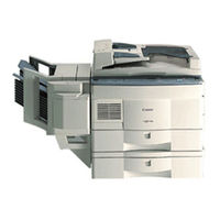
Canon NP7161 Service Manual (395 pages)
Brand: Canon
|
Category: Copier
|
Size: 10.07 MB
Table of Contents
-
Introduction
3
-
System Configuration
5
-
Contents
7
-
Features
17
-
Specifications
18
-
Copier
18
-
Type
18
-
Mechanisms
18
-
Performance
19
-
Cassette Feeding Module — C1
24
-
Names of Parts
25
-
External View
25
-
Cassette Feeding Module
26
-
Cross Section
27
-
Operating the Machine
29
-
Control Panel
29
-
User Mode
31
-
Outline
31
-
Routine Maintenance (by the User)
34
-
Points by Note (by the User)
35
-
Image Formation
36
-
Static Latent Image Formation Block
37
-
Basic Operation
41
-
Basic Mechanisms
41
-
Functional Construction
41
-
Outline of the Electrical Circuitry
42
-
Basic Sequence of Operations at Power-On
44
-
Basic Sequence of Operations at Copy Start
46
-
Main Motor (M1) Control Circuitry
48
-
Operation
48
-
Detecting an Error
48
-
Inputs to the DC Controller
49
-
Outputs from the DC Controller
52
-
Inputs to and Outputs from Accessories
56
-
Exposure System
59
-
Outline of Operation
59
-
Changing the Reproduction Ratio
59
-
Lens Drive System
61
-
Driving the Lens
61
-
Motor Control Circuit
62
-
DC Controller PCB
62
-
Moving the Lens
63
-
Scanner Drive System
64
-
Scanner Motor Control Circuit
65
-
Relationship between Scanner Sensor and Signals
65
-
Basic Sequence of Operations (Scanner)
66
-
Scanner Movement in Page Separation Mode
67
-
Detecting the Original Size
68
-
Detection of the Original Size by the ADF
68
-
Document Size Detection by Document Sensor (NP7210 Only)
69
-
Document Size
72
-
Disassembly/Assembly
73
-
Scanner Drive Assembly
74
-
Removing the Scanner Motor
74
-
Removing the Scanner Drive Cable
75
-
Routing the Scanner Drive Cable
77
-
Adjusting the Position of the Mirror
78
-
Adjusting the Tension of the Scanner Drive Cable
79
-
Lens Drive Assembly
80
-
Removing the Lens Drive Motor
80
-
Removing the Mirror Motor
81
-
Image Formation System
85
-
Outline of the Processes
85
-
Basic Sequence of Operations (Image Formation System)
86
-
NP7161/NP7160 (A4, 2 Copies)
86
-
NP7210 (A4, 2 Copies)
86
-
Controlling the Intensity of the Scanning Lamp
87
-
Protection Mechanisms
89
-
Controlling the Primary/Transfer Bias
90
-
Controlling the Developing/Separation Static Eliminator Bias
91
-
Turning On/Off the Developing DC Bias
92
-
Turning On/Off the Developing AC Bias/Separation Eliminator Bias
93
-
Controlling the Developing DC Bias to a Specific Voltage to Suit Copy Density
94
-
Controlling the Blank Exposure Lamp
96
-
Turning on the Blank Exposure Lamp in Reduce Mode
97
-
Turning on the Blank Exposure Lamp in Direct/Enlarge Mode
97
-
Turning on the Blank Exposure Lamp in Multifeeder Mode
97
-
Developing Assembly/Drum Cleaner
98
-
Detecting and Controlling the Level of Toner
100
-
Monitoring the Waste Toner Feeding Screw
101
-
Monitoring the Waste Toner Box
102
-
Control by the Cleaner Thermistor
104
-
Copying Speed down Sequence
104
-
Auto Density Adjustment (AE)
105
-
Measuring the Density of the Original
105
-
Scanning Lamp Assembly
108
-
Removing the Scanning Lamp
108
-
Mounting the Scanning Lamp
109
-
Removing the Thermal Fuse
109
-
Exposure Assembly
110
-
Removing the Pre-Exposure/Blank Exposure Lamp Assembly
110
-
Removing the Dust-Proofing Glass
110
-
Cleaning the no 6 Mirror
111
-
Drum Unit
112
-
Removing the Drum Unit
112
-
Cleaning the Photosensitive Drum
113
-
Removing the Cleaner Thermistor
113
-
Primary Charging Assembly
114
-
Removing the Primary Charging
114
-
Transfer Charging Assembly
115
-
Removing the Transfer Charging Assembly
115
-
Charging Wire
116
-
Stringing the Charging Wires
116
-
Adjust the Height of the Charging Wires
120
-
Developing Assembly
121
-
Removing the Developing Assembly
121
-
Removing the Developing Blade
121
-
Removing the Developing Cylinder
122
-
Pick-Up/Feeding System
127
-
Pick-Up from the Cassette
128
-
Pick-Up Operation
128
-
Sequence of Operations (Pick-Up/Feeding)
129
-
NP7210 Vertical Path Paper Control (A4, 2 Sheets)
130
-
Operation of the Cassette Lifter
131
-
Detecting the Size of the Cassette
133
-
Detecting the Cassette Size
134
-
Pick-Up from the Multifeeder
135
-
Detecting the Size of Paper in the Multifeeder
136
-
Sequence of Operation (Pick-Up from Multifeeder)
137
-
Controlling the Registration Clutch
138
-
Sequence of Operations (Jam Detection)
140
-
Registration Delay Jam
140
-
Registration Stationary Jam
140
-
Delivery Delay Jam
141
-
Delivery Stationary Jam
141
-
Pick-Up Assembly
143
-
Removing the Pick-Up Roller
143
-
Mounting the Pick-Up Roller
143
-
Removing the Pick-Up Drive Assembly
144
-
Removing the Pick-Up Assembly
144
-
Removing the Feed Roller
145
-
Removing the Separation Roller
145
-
Mounting the Separation Roller
146
-
Multifeeder Asseembly
147
-
Removing the Multifeeder Tray
147
-
Removing the Multifeeder Assembly
147
-
Removing the Multifeeder Pick-Up Roller
148
-
Removing the Separation Pad
148
-
Adjusting the Pressure of the Separation Pad
149
-
Removing the Registration Roller Assembly
150
-
Cassette Assembly
151
-
Removing the Cassette Size Switch
151
-
Changing the Cassette Size (AB/INCH)
152
-
Adjusting the Left/Right Registration
153
-
Fixing System
157
-
Controlling the Fixing Temperature
158
-
Copy Speed Reducing Sequence (NP7210 Only)
161
-
Error Detection Circuit
164
-
Surface Temperature of the Fixing Upper Roller
165
-
Activation of the Fixing Heater (H1)
165
-
Fixing Assembly
169
-
Construction
169
-
Locking Mechanism
169
-
Removing the Fixing Assembly
169
-
Removing the Fixing Heater
171
-
Removing the Thermal Switch Assembly
172
-
Removing the Main Thermistor
173
-
Removing the Sub Thermistor
173
-
Removing the Fixing Upper Roller
174
-
Removing the Fixing Lower Roller
175
-
Removing the Heat Discharge Roller
175
-
Adjusting the Height of the Fixing Inlet Guide
175
-
Adjusting the Nip
176
-
Measuring the Nip
176
-
Delivery Assembly
177
-
Removing the Upper Separation Claw
177
-
Removing the Lower Separation Claw
177
-
Removing the Delivery Roller
178
-
Removing the Upper Left Cover
191
-
Removing the Delivery Lower Cover
191
-
Removing the Delivery Upper Cover
191
-
Removing the Lower Inside Cover
192
-
Control Panl
193
-
Removing the Control Panel
193
-
Copyboaed Glass
194
-
Removing the Copyboard Glass
194
-
Fans
195
-
Removing the Scanner Cooling Fan
195
-
Removing the Exhaust Fan
196
-
Remove the Ozone Filter
197
-
Counter Assembly
198
-
Main Motor Assembly
198
-
Removing the Counter Assembly
198
-
Removing the Main Motor Assembly
198
-
Removing the DC Controller PCB
199
-
Points to Note When Replacing the DC Controller PCB
199
-
Removing the Power Supply PCB
200
-
Removing the High-Voltage Power Supply PCB
200
-
Lamp Regulator PCB
201
-
Removing the Lamp Regulator PCB
201
-
Inputs to and Outputs from Cassette Relay PCB
205
-
Cassette Feeding
206
-
Cassette Motor Control Circuit
207
-
Pick-Up/Feeding Sequence
208
-
Vertical Path Paper Control of NP7161 and NP7160
209
-
Vertical Path Paper Control of NP7210
210
-
Waste Toner Swing Control
211
-
Jam Detection
212
-
Jam Detection Sequence
213
-
External Cover
215
-
Removing the Upper Front Cover
215
-
Drive Assembly
216
-
Removing the Cassette Motor
216
-
Removing the Pick-Up Rollers
217
-
Installing the Pick-Up Rollers
217
-
Removing the Feed Rollers
219
-
Removing the Separation Rollers
219
-
Installing the Separation Rollers
220
-
Cassette Size Switch Assembly
221
-
Cassette Relay PCB
223
-
Removing the Cassette Relay PCB
223
-
Installation
227
-
Selecting the Site
227
-
Unpacking and Installation
228
-
Removing the Metal Fixings
229
-
Mounting the Drum Unit
230
-
Cleaning the Parts and Making Checks
232
-
Checking the Images/Operations and User Mode
234
-
Supplying Toner
236
-
Relocating the Machine
238
-
Installing the Control Card IV N
239
-
Installing the Remote Diagnostic Device II
240
-
Installing the Accessory Counter
249
-
Procedure for Installing the Accessory Heater
251
-
Installing the Heater Switch
251
-
Installing the Cassette/Drum Heater
253
-
Installing the Mirror Heater
255
-
Installing the Cassette Heater
256
-
Maintenance and Service
261
-
Periodically Replaced Parts
261
-
Consumables and Durables
262
-
Scheduled Servicing Chart
264
-
Scheduled Servicing Table
266
-
Guide to Troubleshooting Tables
271
-
Standards and Adjustments
275
-
Mechanical
275
-
Leading Edge Non-Image Width (Blank Exposure Lamp off Timing)
275
-
Image Leading Edge Margin (Registration on Timing)
275
-
Left/Right Registration (Cassette)
276
-
Routing the Scanner Drive Cble
277
-
Adjusting the Height of the Charging Wires
283
-
Adjusting the Height of the Fixing Assembly Inlet Guide
286
-
Adjusting the Pressure of the Lower Roller
286
-
Electrical System
288
-
Obtaining Optimum Exposure
288
-
AE Adjustment
289
-
After Replacing the DC Controller PCB
292
-
Checking the Photointerrupters
293
-
Image Faults
297
-
Initial Checks
297
-
Checking the Site Environment
297
-
Checking the Originals
297
-
Checking the Charging Assembly
298
-
Checking the Developing Assembly
298
-
Checking the Paper
298
-
Checking the Periodically Replaced Parts
298
-
Troubleshooting Image Faults
301
-
The Copy Is too Light (Halftone Area Only)
301
-
The Copy Has Uneven Density (Front Side Dark)
303
-
The Copy Has Uneven Density (Front Side Light)
303
-
The Copy Is Foggy (Overall)
304
-
The Copy Is Foggy (Vertical)
305
-
The Copy Has Black Lines (Vertical, Fuzzy, Thick)
305
-
The Copy Has Black Lines (Vertical, Thin)
305
-
The Copy Has White Spots (Vertical)
306
-
The Copy Has White Lines (Vertical)
306
-
The Back of the Copy Is Soiled
308
-
The Copy Has Faulty Fixing
309
-
The Copy Has a Displaced Leading Edge
310
-
The Copy Has a Blurred Image
311
-
The Copy Is Foggy (Horizontally)
311
-
The Copy Has Poor Sharpness
312
-
The Copy Is Blank
313
-
The Copy Is Solid Black
313
-
Troubleshooting Malfunctions
314
-
E000
314
-
E001
315
-
E002/E003
316
-
E004
317
-
E010
317
-
E013
317
-
E030
318
-
E031
318
-
E202 (the Keys on the Control Panel Fail to Operate)
318
-
E208
319
-
E210
319
-
E220
319
-
E261
320
-
E710/E711
320
-
E712
320
-
E717
320
-
E800
321
-
E805
321
-
E821
321
-
AC Power Is Absent
322
-
DC Power Supply Is Absent
323
-
The Scanner Fails to Move
324
-
The Lens Fails to Move
325
-
The Mirror Fails to Move
325
-
The Scanning Lamp Fails to Turn on
326
-
The Pre-Exposure Lamp Fails to Turn on
327
-
The Blank Exposure Lamp Fails to Turn on
327
-
Pick-Up Fails (Cassette)
328
-
Pick-Up Operation Fails (Multifeeder)
329
-
The Registration Roller Fails to Rotate
329
-
The Fixing Heater Fails to Mturn on
330
-
The Add Toner Indicator Does Not Flash/Turn on
330
-
The Add Toner Indicator Fails to Turn off
331
-
The Waste Toner Box Full Indicator Fails to Flash/Turn on
331
-
The Waste Toner Box Full Indicator Fails to Turn off
332
-
The Add Paper Indicator Fails to Flash
332
-
The Add Paper Indicator Fails to Turn off
333
-
The Jam Indicator Fails to Flash
333
-
The Jam Indicator Fails to Turn off
334
-
The Set Control Card Indicator Fails to Turn on
334
-
The Set Control Card Indicator Fails to Turn off
334
-
E904
335
-
Fails to Pick up
336
-
Load Paper Indicator Fails to Flash
337
-
Load Paper Indicator Fails to Extinguish
337
-
Troubleshooting Feeding Problems
338
-
Copy Jams
338
-
Pick-Up /Feeding Assembly
339
-
Fixing/Delivery Assembly
340
-
Faulty Feeding
341
-
Double Feeding
341
-
Wrinkles
341
-
Arrangement and Functions of Electrical Parts
342
-
Motors, Fans,Clutches and Solenoids
344
-
Heater, Lamps and Others
346
-
Pcbs
348
-
Variable Resistors, Light-Emitting Diodes and Check Pins by PCB
350
-
Power Supply PCB
353
-
High-Voltage Power Supply PCB
354
-
Service Mode
355
-
Using Service Mode
355
-
Starting Service Mode
355
-
Selecting Service Mode
355
-
Using Adjust Mode and Function Mode
356
-
Display Mode
357
-
Guide to Jam Types and Jam History
358
-
Guide to ADF Jam History and ADF Jam Type
359
-
Guide to ADF Warning
359
-
Guide to Sorter Jam History and Sorter Jam Type
359
-
Guide to Sorter Tray Warning
360
-
Checking the Control Panel Keys
360
-
How to Read no 127 Document Size Indicator (NP7210 Only)
361
-
I/O Display Mode
362
-
Guide to Nos 202, 203, 204, 205, 219, 220, 221, 222 and 223
363
-
Adjust Mode
366
-
Function Mode
368
-
Option Mode
369
-
Paper Sizes Available under no 505/506
371
-
Counter Mode
372
-
Application Mode
373
-
Self Diagnosis
374
-
Adf
378
-
Sorter
379
-
Special Tools List
391
-
Solvents and Oils
392
Advertisement
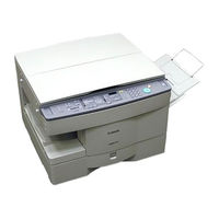
Canon NP7161 Service Manual (346 pages)
Brand: Canon
|
Category: Printer
|
Size: 2.66 MB
Table of Contents
-
Table of Contents
9
-
System Configuration
7
-
General Description
17
-
Chapter 1 General Description
19
-
Features
19
-
Specifications
20
-
Copier
20
-
Mechanisms
20
-
Type
20
-
Performance
21
-
Others
23
-
-
-
Names of Parts
26
-
External View
26
-
Cross Section
27
-
Copier
27
-
-
Operating the Machine
28
-
Control Panel
28
-
User Mode
30
-
-
Routine Maintenance (by the User)
32
-
VII.image Formation
34
-
Outline
34
-
-
-
-
Chapter 2 Basic Operation
37
-
Basic Operation
37
-
Basic Mechanisms
39
-
Functional Construction
39
-
Outline of the Electrical Circuitry
40
-
Power-On
41
-
Basic Sequence of Operations at
42
-
-
Basic Sequence of Operations
42
-
Basic Sequence of Operations at Copy Start
44
-
Main Motor (M1) Control Circuitry
46
-
Detecting an Error
46
-
Operation
46
-
-
Outline
46
-
Inputs to the DC Controller
47
-
Inputs to the DC Controller (3/3)
49
-
Outputs from the DC Controller
50
-
Outputs from the DC Controller (1/4)
50
-
Outputs from the DC Controller (2/4)
51
-
-
-
Chapter 3 Exposure System
55
-
Outline of Operation
57
-
Changing the Reproduction Ratio
57
-
-
Lens Drive System
59
-
Driving the Lens
59
-
Outline
59
-
Motor Control Circuit
60
-
Moving the Lens
61
-
-
-
Scanner Drive System
62
-
Outline
62
-
Scanner Motor Control Circuit
63
-
Relationship between Scanner Sensor and Signals
63
-
Basic Sequence of Operations (Scanner)
64
-
Scanner Movement in Page Separation Mode
65
-
-
Others
66
-
Detecting the Original Size
66
-
Detection of the Original Size by the ADF
66
-
Disassembly/Assembly
67
-
Scanner Drive Assembly
68
-
Removing the Scanner Drive Cable
69
-
Routing the Scanner Drive Cable
71
-
Adjusting the Position of the Mirror
72
-
Adjusting the Tension of the Scanner Drive Cable
73
-
Lens Drive Assembly
74
-
Removing the Lens Drive Motor
74
-
-
-
-
Chapter 4 Image Formation System
77
-
Image Formation System
77
-
Outline of the Processes
79
-
Outline
79
-
Basic Sequence of Operations (Image Formation System)
80
-
Controlling the Intensity of the Scanning Lamp
81
-
Outline
81
-
Operation
82
-
Protection Mechanisms
83
-
-
Controlling the Primary/Transfer Bias
84
-
Outline
84
-
Turning On/Off the Primary/Transfer Bias
84
-
-
Controlling the Developing/Separation Static Eliminator Bias
85
-
Outline
85
-
Turning On/Off the Developing
86
-
Turning On/Off the Developing DC Bias
86
-
AC Bias/Separation Eliminator Bias
87
-
Controlling the Developing
88
-
-
Controlling the Blank Exposure Lamp
90
-
Outline
90
-
Turning on the Blank Exposure Lamp in Direct/Enlarge Mode
91
-
Turning on the Blank Exposure Lamp in Reduce Mode
91
-
Motor
92
-
Outline
92
-
-
-
Developing Assembly/Drum Cleaner Assembly
92
-
Detecting and Controlling the Level of Toner
94
-
Monitoring the Waste Toner Feeding Screw
95
-
Monitoring the Waste Toner Box
96
-
Control by the Cleaner Thermistor
98
-
Copying Speed down Sequence
98
-
-
Auto Density Adjustment (AE)
99
-
Measuring the Density of the Original
99
-
Outline
99
-
-
-
Disassembly/Assembly
101
-
Scanning Lamp Assembly
102
-
Removing the Scanning Lamp
102
-
Mounting the Scanning Lamp
103
-
Removing the Thermal Fuse
103
-
-
Exposure Assembly
104
-
Removing the Dust-Proofing Glass
104
-
Removing the Pre-Exposure/Blank Exposure Lamp Assembly
104
-
Cleaning the No. 6 Mirror
105
-
-
Drum Unit
106
-
Removing the Drum Unit
106
-
Cleaning the Photosensitive Drum
107
-
Removing the Cleaner Thermistor
107
-
-
Primary Charging Assembly
108
-
Removing the Primary Charging Assembly
108
-
-
Transfer Charging Assembly
109
-
Removing the Transfer Charging Assembly
109
-
-
Charging Wire
110
-
Stringing the Charging Wires
110
-
Adjusting the Height of the Charging Wires
114
-
-
Developing Assembly
115
-
Removing the Developing Blade
115
-
Removing the Developing Cylinder
116
-
-
-
-
Chapter 5 Pick-Up/Feeding System
119
-
Outline of Operation
121
-
Pick-Up from the Cassette
122
-
Pick-Up Operation
122
-
Sequence of Operations (Pick-Up/Feeding)
123
-
Operation of the Cassette Lifter
124
-
Detecting the Size of the Cassette
126
-
Outline
126
-
Detecting the Cassette Size
127
-
-
-
Pick-Up from the Multifeeder
128
-
Pick-Up Operation
128
-
Detecting the Size of Paper in the Multifeeder
129
-
Sequence of Operations (Pick-Up from Multifeeder)
130
-
-
Controlling the Registration Clutch
131
-
Detecting Jams
132
-
Outline
132
-
Sequence of Operations (Jam Detection)
133
-
Registration Delay Jam
133
-
Registration Stationary Jam
133
-
Delivery Delay Jam
134
-
Delivery Stationary Jam
134
-
-
-
Disassembly/Assembly
135
-
Pick-Up Assembly
136
-
Removing the Pick-Up Roller
136
-
Assembly
137
-
-
Removing the Pick-Up Drive
137
-
Assembly
140
-
-
-
Multifeeder Assembly
140
-
Removing the Multifeeder Tray
140
-
Removing the Multifeeder Assembly
140
-
Removing the Multifeeder
140
-
Removing the Separation Pad
141
-
Adjusting the Pressure of the Separation Pad
142
-
-
Registration Roller Assembly
143
-
Removing the Registration Roller Assembly
143
-
-
Cassette Assembly
144
-
Removing the Cassette Size Switch
144
-
Changing the Cassette Size (AB/INCH)
145
-
Adjusting the Left/Right Registration
146
-
-
-
Chapter 6 Fixing System
147
-
Fixing System
147
-
Outline of Operation
149
-
Outline
149
-
Controlling the Fixing Temperature
150
-
Error Detection Circuit
153
-
Outline
153
-
Activation of the Fixing Heater (H1)
154
-
Surface Temperature of the Fixing Upper Roller
154
-
-
-
Disassembly/Assembly
155
-
Fixing Assembly
156
-
Construction
156
-
Locking Mechanism
156
-
Removing the Fixing Assembly
156
-
Removing the Fixing Heater
158
-
Assembly
159
-
Removing the Thermal Switch
159
-
-
Removing the Main Thermistor
160
-
Removing the Sub Thermistor
160
-
Removing the Fixing Upper Roller
161
-
Adjusting the Height of the Fixing Inlet Guide
162
-
Removing the Fixing Lower Roller
162
-
Removing the Heat Discharge Roller
162
-
-
Adjusting the Nip
163
-
Delivery Assembly
164
-
Removing the Lower Separation Claw
164
-
Removing the Upper Separation Claw
164
-
-
Removing the Delivery Roller
165
-
-
-
Chapter 7 Externals/Auxiliary Mechanisms
167
-
Fans
169
-
Power Supply
172
-
Outline of Power Supply
172
-
Power Supply Circuitry
173
-
AC Power Supply
173
-
DC Power Supply
173
-
ADF and Sorter
174
-
Mirror Heater, Cassette/Drum Heater, and Accessory Cassette Heater
174
-
-
Protection Mechanisms of the Power Supply Circuitry
175
-
-
Disassembly/Assembly
176
-
External Covers
177
-
Removing the Right Door
178
-
Removing the Upper Right Cover
178
-
Inside Cover
179
-
Removing the Delivery Lower Cover
179
-
Removing the Delivery Upper Cover
179
-
Removing the Upper Left Cover
179
-
Removing the Lower Inside Cover
180
-
Control Panel
181
-
Removing the Control Panel
181
-
-
Copyboard Glass
182
-
Removing the Scanner
183
-
Fans
183
-
Removing the Counter Assembly
186
-
-
Main Motor Assembly
186
-
Removing the Main Motor Assembly
186
-
Counter Assembly
186
-
-
DC Controller PCB
187
-
Removing the DC Controller PCB
187
-
Points to Note When Replacing
187
-
The DC Controller PCB
187
-
-
-
Removing the High-Voltage Power Supply PCB
188
-
Removing the High-Voltage
188
-
-
Removing the Power Supply PCB
188
-
Power Supply PCB
188
-
-
Lamp Regulator PCB
189
-
Removing the Lamp Regulator PCB
189
-
-
-
Chapter 8 Installation
191
-
Selecting the Site
193
-
Unpacking and Installation
194
-
Unpacking
194
-
Removing the Metal Fixings
195
-
Mounting the Drum Unit
196
-
Cleaning the Parts and Making Checks
198
-
Checking the Images/Operations and User Mode
200
-
Supplying Toner
202
-
-
Relocating the Machine
204
-
IV. Installing the Control Card IV N
205
-
Installing the Remote Diagnostic Device II
206
-
Installing the Accessory Counter
215
-
VII.installing the Accessory Heater
217
-
Installing the Heater Switch
217
-
Mounting the Cassette/Drum Heater
218
-
Installing the Mirror Heater
219
-
-
-
-
Chapter 9 Maintenance and Servicing
221
-
Periodically Replaced Parts
223
-
Copier
223
-
-
Consumables and Durables
224
-
Copier
224
-
Scheduled Servicing Chart
225
-
Scheduled Servicing Table
227
-
Copier
227
-
-
-
-
Chapter 10 Troubleshooting
229
-
Guide to Troubleshooting Tables
231
-
Image Adjustment Basic Procedure
233
-
Points to Note for Scheduled Servicing
234
-
Standards and Adjustments
235
-
Mechanical
235
-
Image Leading Edge Margin (Registration on Timing)
235
-
Leading Edge Non-Image Width (Blank Exposure Lamp off Timing)
235
-
Width (Blank Exposure Lamp off Timing)
235
-
Left/Right Registration (Cassette)
236
-
-
Exposure System
237
-
Routing the Scanner Drive Cable
237
-
Adjusting the Position of the Mirror
238
-
Adjusting the Tension of the Scanner Drive Cable
239
-
-
Image Formation System
240
-
Outline
240
-
Stringing the Charging Wires
240
-
Adjusting the Height of the Charging Wires
243
-
-
Pick-Up/Feeding System
244
-
Adjusting the Pressure of the Separation Pad
244
-
Changing the Cassette Size
244
-
Adjusting the Height of the
246
-
Adjusting the Pressure of the Lower Roller (Nip)
246
-
Fixing System
246
-
-
Electrical System
248
-
Obtaining Optimum Exposure
248
-
AE Adjustment
249
-
After Replacing the DC Controller PCB
252
-
Checking the Photointerrupters
253
-
-
-
Image Faults
255
-
Initial Checks
255
-
Checking the Copyboard Cover and Copyboard Glass
255
-
Checking the Originals
255
-
Checking the Site Environment
255
-
Checking the Charging Assembly
256
-
Checking the Developing Assembly
256
-
Checking the Paper
256
-
Checking the Periodically Replaced Parts
256
-
Others
256
-
-
Image Fault Samples
258
-
Troubleshooting Image Faults
259
-
The Copy Is too Light
259
-
-
Troubleshooting
259
-
The Copy Is too Light
260
-
The Copy Has Uneven Density
261
-
The Copy Is Foggy. (Overall)
262
-
The Copy Has Black Lines
263
-
The Copy Is Foggy. (Vertical)
263
-
The Copy Has White Lines
264
-
The Copy Has White Spots
264
-
The Copy Has White Spots
265
-
The Back of the Copy Is Soiled
266
-
The Copy Has Faulty Fixing
267
-
Leading Edge
268
-
The Copy Has a Displaced Leading Edge
268
-
The Copy Has a Blurred Image
269
-
The Copy Is Foggy
269
-
The Copy Has Poor Sharpness
270
-
The Copy Is Blank
271
-
The Copy Is Solid Black
271
-
-
-
Troubleshooting Malfunctions
272
-
IV. Troubleshooting Malfunctions
272
-
Copier
272
-
E000
272
-
E001
273
-
E002/E003
274
-
E004
275
-
E010
275
-
E013
276
-
E030
276
-
E031
277
-
E202 (the Keys on the Control Panel Fail to Operate.)
277
-
E208
278
-
E210
278
-
E220
279
-
E261
279
-
E710/E711
279
-
E712
280
-
E717
280
-
E800
281
-
E805
281
-
E821
281
-
AC Power Is Absent
282
-
DC Power Supply Is Absent
283
-
The Scanner Fails to Move
284
-
The Lens Fails to Move
285
-
The Mirror Fails to Move
285
-
The Scanning Lamp Fails to Turn on
286
-
The Blank Exposure Lamp Fails to Turn on
287
-
The Pre-Exposure Lamp Fails to Turn on
287
-
Pick-Up Fails. (Cassette)
288
-
Pick-Up Operation Fails
289
-
The Registration Roller Fails to Rotate
289
-
The Add Toner Indicator Does Not Flash/Turn on
290
-
The Fixing Heater Fails to Turn on
290
-
The Add Toner Indicator Fails to Turn off
291
-
The Waste Toner Box Full Indicator Fails to Flash/Turn on
291
-
The Add Paper Indicator Fails to Flash
292
-
The Waste Toner Box Full Indicator Fails to Turn off
292
-
The Add Paper Indicator Fails to Turn off
293
-
The Jam Indicator Fails to Flash
293
-
The Jam Indicator Fails to Turn off
294
-
The Set Control Card Indicator Fails to Turn on
294
-
The Set Control Card Indicator Fails to Turn off
295
-
-
-
Troubleshooting Feeding Problems
296
-
Copy Jams
296
-
Pick-Up/Feeding Assembly
297
-
Fixing/Delivery Assembly
298
-
-
Faulty Feeding
299
-
Double Feeding
299
-
Wrinkles
299
-
-
-
Arrangement and Functions of Electrical Parts
300
-
Sensors and Switches
300
-
Motors, Fans, Clutches, and Solenoids
302
-
Heaters, Lamps, and Others
304
-
Pcbs
306
-
Variable Resistors, Light-Emitting Diodes, and Check Pins by PCB
307
-
DC Controller PCB
307
-
Lamp Regulator PCB
310
-
Power Supply PCB
310
-
High-Voltage Power Supply PCB
311
-
-
-
Service Mode
312
-
Outline
312
-
Using Service Mode
312
-
Selecting Service Mode
312
-
Starting Service Mode
312
-
-
Using Adjust Mode and Function Mode
313
-
Display Mode [1]
314
-
I/O Display Mode [2]
318
-
-
F. Adjust Mode [3]
322
-
Function Mode [4]
324
-
Option Mode [5]
325
-
Counter Mode [6]
327
-
Application Mode [7]
328
-
-
Self Diagnosis
329
-
A. Copier
329
-
-
B. Adf
333
-
Sorter
334
-
Cassette Feeding Module
334
-
-
Appendix
335
-
Special Tools List
343
-
Solvents and Oils
344
-
-
Advertisement
Related Products
-
Canon NP7160
-
Canon NP7210
-
Canon NP-70
-
Canon NP6350
-
Canon NP6251
-
Canon NP-2120
-
Canon NP6551
-
Canon NP6016
-
Canon NP6012
-
Canon NP6212
Canon Categories
![]()
Printer
![]()
Digital Camera
![]()
All in One Printer
![]()
Camcorder
![]()
Scanner
More Canon Manuals
Руководстве по эксплуатации Canon NP7161 — вам приходилось его терять? Поскольку вы попали сюда, наверняка с вами это случилось. Но вы не единственный человек, сталкивающийся с проблемами с хранением руководства по эксплуатации всех домашних устройств. Ниже несколько советов, касающихся того, зачем собирать руководства по эксплуатации.
Руководстве по эксплуатации Canon NP7161 это определенный вид технической документации, являющейся неразлучным элементом каждого устройства, которое мы приобретаем. Они отличаются между собой количеством информации, которую можно найти на тему данного устройства: напр. Canon NP7161. Конечно же, если производитель считает что необходимо передать нам большее количество информации, касающейся устройства Canon NP7161, то стоит ее хоть раз прочитать — в начале, сразу же после покупки данной вещи. Однако мы считаем, что инструкции должны заключать самую важную, наиболее необходимую информацию о Canon NP7161, так, чтобы не отнимать желания пользователя прочесть ее уже в самом начале. Несомненно, если устройство Canon NP7161 имеет много продвинутых функций, неизбежно большое количество информации в содержании этого документа.
Które из информации в инструкции Canon NP7161 необходимо обязательно прочитать?
- Информацию, касающуюся правильного использования и ухода за устройством Canon NP7161 — нам необходимо ознакомиться с основными правилами, чтобы в случае проблем с устройством сервисный центр не отказал нам в гарантийном обслуживании, из-за неправильного использования
- Информация, касающаяся самых частых проблем с Canon NP7161 и способы их решения
- Информация, касающаяся гарантии устройства Canon NP7161 и ближайших сервисных центров, способных починить устройство в соответствии с рекомендациям производителя Canon
Как хранить инструкции дома?
Хорошей идеей является предназначение одного ящика, в котором бы хранилась инструкция Canon NP7161 а также всех других домашних устройств которыми мы пользуемся. Тогда значительно легче вам будет ее найти, чем искать в родных коробках, которые наверняка уже выбросили вы, или другие домочадцы. Раз в год достаточно просмотреть ящик и выбросить инструкции, которые касаются устройств, которыми вы уже не пользуетесь. Таким образом вы избежите хранения ненужных документов, а останутся только актуальные. Вы можете также скачать и распечатать инструкцию Canon NP7161 чтобы разместить ее в своем ящике.
Похожие инструкции
Скачать
COPYRIGHT © 1998 CANON INC.
CANON NP7161/NP7160 REV.0 AUG. 1998 PRINTED IN JAPAN (IMPRIME AU JAPON)
FY8-13FB-000
AUG. 1998
SERVICE
MANUAL
REVISION 0
Download Service Manual And Resetter Printer at http://printer1.blogspot.com