Specifications:805/805712-pgd1.pdf file (11 Dec 2022) |
Accompanying Data:
Carel PGD1 Monitor PDF Install Instructions (Updated: Sunday 11th of December 2022 09:09:34 PM)
Rating: 4.7 (rated by 61 users)
Compatible devices: PGD1000N00, Pro Lite E1902S-1, pGD2, CQ-VD7005W, PGD1000I00, PGD1000F00, SP2309WFP, PGD0000F00.
Recommended Documentation:
Text Version of Manual, Install Instructions
(Ocr-Read Summary of Contents of some pages of the Carel PGD1 Document (Main Content), UPD: 11 December 2022)
-
1, Carel PGD1 ECCIII RIU Install Instructions SUPERSEDES: none FORM NO: RPW02-PGD1RIU-20140711 1 of 2 PGD1 Remote Interface Unit (RIU) Installation PoolPak Part #: 24-0145 Manufacturer: Carel PPK Models: PoolComPak (ECCPCP), RoofPak (ECCPCP), PoolPak MPK (ICC) INTRODUCTION The Remote Inter…
-
2, ECCIII RIU Install Instructions SUPERSEDES: none FORM NO: RPW02-PGD1RIU-20140711 2 of 2 WIRING Proper polarity and connection is essential for correct operation of the RIU. Improper wiring can cause permanent damage. See below for the correct cable to connect the RIU (plug in…
-
Carel PGD1 User Manual
-
Carel PGD1 User Guide
-
Carel PGD1 PDF Manual
-
Carel PGD1 Owner’s Manuals
Recommended: COMP-61, D3902464, LER6914


-
Siemens SIMATIC HMI series
___________________ ___________________ ___________________ ___________________ ___________________ ___________________ ___________________ ___________________ ___________________ ___________________ ___________________ ___________________ ___________________ ___________________ ___________________ SIMATIC HM …
SIMATIC HMI series 288
-
Samsung UN49MU7600
7 SERIES7 SÉRIEThank you for purchasing this Samsung product.To receive more complete service, please register your product at www.samsung.com/registerModel Serial No. If you have any questions, please call us at 1 …
UN49MU7600 48
-
Honeywell 7800 SERIES
INSTALLATION INSTRUCTIONS32-00209-03SIL3CapableRM7898A7800 SERIES Valve Proving Primary Relay ModulesAPPLICATIONThe RM7898 is a microprocessor-based integrated burner control for automatically fired gas, oil or combination fuel single burner applications. The RM7898 system consist of a relay module, …
7800 SERIES 32
-
VarTech Systems VT420D
VT420D Large Screen Desktop User’s Guide Read these instructions completely before attempting to operate your new Color Display USER MANUAL Solutions for Demanding ApplicationsIndustrial CRT and Flat Panel Displays VARTECH S Y S T E M S I N C. …
VT420D 24
Additional Information:
Popular Right Now:
Operating Impressions, Questions and Answers:

ECCIII RIU Install Instructions
SUPERSEDES:
none
FORM NO:
RPW02-PGD1RIU-20140711
PGD1 Remote Interface Unit (RIU) Installation
PoolPak Part #: 24-0145
Manufacturer: Carel
PPK Models: PoolComPak (ECCPCP), RoofPak (ECCPCP), PoolPak MPK (ICC)
INTRODUCTION
The Remote Interface Unit (RIU) is the main user interface for the ECCPCP and ICC control
systems. It can be installed at the PoolPak unit or in another convenient location up to 1000 feet
away. Each PoolPak supports connection to as many as three RIUs. All status, set points and
configuration points are available through the RIU.
MOUNTING
The RIU should be mounted in a convenient location, outside the natatorium, that is protected
from splashing pool water and corrosive air. The ambient temperature of the mounting location
must always be greater than 32°F. The maximum distance from the PoolPak control panel is
1,000 feet. For distances greater than 1,000 feet, contact the factory.
Warning!
Failures due to mounting the keypad inside the pool room will not be covered under warranty.
The wall mounting of the terminal first requires the back piece (A) of the RIU assembly. The RIU
is designed to fit a single gang, extra-deep electrical box mounted horizontally in the wall. The
RJ25 jack and most of the black cable should be placed inside the box before installing the
mounting bracket. A ¾” hole must be drilled for the 6-conductor cable which connects the
remote interface unit to the PoolPak unit. See figure below and detailed instructions.
1. Fasten the back piece (A) to the gang box
using the rounded-head screws supplied in
the packaging. Use the screws that come
with the box to secure the bracket.
2. Thread the 6-conductor cable through the
back piece (A) and connect to the back of
front panel (B).
3. Rest the front panel (B) on the back piece
A and fasten the parts together using the
flush-head screws supplied in the packaging.
4. Finally, fit the click-on frame (C).
1 of 2
ECCIII RIU Install Instructions
SUPERSEDES:
none
FORM NO:
RPW02-PGD1RIU-20140711
WIRING
Proper polarity and connection is essential for correct operation of the RIU. Improper wiring can
cause permanent damage. See below for the correct cable to connect the RIU (plug in back)
with each model controller. At minimum, cable must be 6-conductor (three twisted pairs), 16-20
AWG.
Controller
ECCPCP
ICC
Type of Cable
RJ-12 Black Crossover
RJ-12 Black Crossover
Control Connection
Plug J10 at ECCPCP Ctrl
Plug J10 CMI
For hard-wiring the RIU to the controller, refer to the field wiring diagram in the Installation and
Operation Manual specific to your unit.
CONFIGURATION
The RIU network address is set by pressing the UP, DOWN, and ENTER buttons
simultaneously and holding them down for approximately 5 seconds. The display will show
“Display address setting”. Press ENTER to move the cursor to the current address field. Use the
UP and DOWN buttons to change the address to either 10, 11, or 12 and press ENTER.
To configure the PGD1 RIU addresses, press the UP, DOWN, and ENTER buttons
simultaneously and hold them down for approximately 5 seconds. The display will show “Display
address setting”. Press the ENTER four times to move the cursor past the screens showing
“Display address setting”, “I/O Board address” and “Terminal config” Press ENTER to continue.
Use the keypad to enter the RIU configuration as follows:
P: 0x
Trm1
Trm2
Trm3
Adr
10
11
12
Priv/Shared
(x = CM1 I/O address)
Sh
Sh
Sh
Ok? Y
When prompted “OK?”, select “Y” to save the configuration and to exit. The RIU will go blank
and then beep several times before bringing up the normal status display.
If you have any questions, please call the PoolPak Service department. (800) 959-7725
2 of 2
Was this manual useful for you?
Yes
No
Thank you for your participation!
* Your assessment is very important for improving the workof artificial intelligence, which forms the content of this project
PGD1*
Общие характеристики
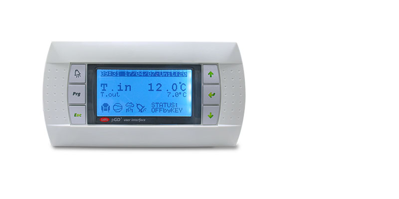
Графические терминалы pGD1/pGD Evolution, представленные в рамках терминалов для контроллеров серии pCO, наиболее универсальны и могут индивидуально настраиваться под собственные предпочтения. В процессе разработки данных терминалов специалисты компании CAREL особое внимание уделили простоте настройки и функциональности, сохранив при этом привлекательный внешний вид. Терминал комплектуется дисплеем с подсветкой и разрешением 132×64 пикселя зеленого или белого цвета и 6 кнопками.
На кнопках терминала pGD1 нанесены символы, которые показываются на встроенном дисплее контроллера серии pCO2/3, а на кнопках терминала pGDE — такие же символы как на кнопках контроллера серии pCO5/5+/c.pCO.
Дисплеи терминалов поддерживают графические объекты разного размера и основные международные буквенно-цифровые символы. Терминалы можно индивидуально настраивать под собственные предпочтения, что является основополагающим принципом всех устройств CAREL семейства pCO, поэтому они идеально подойдут в качестве оптимального варианта всем, кто заинтересован в приобретении современных терминалов по конкурентоспособной стоимости, пусть и в ограниченном количестве. Терминал подсоединяется к контроллеру pCO по сети RS485, работающей по протоколу pLAN.
Документация
Technical
-
2D/3D модели
Код Описание Язык Дата * Выпуск Код
2d-3d pGD1 panelОписание
2D-3D drawingsЯзык
ALLДата
14/01/2014
Выпуск
R0
-
Инструкции по применению
Код Описание Язык Дата * Выпуск Код
+030220335Описание
pCO sistema: Manuale generaleЯзык
ITAДата
17/04/2013
Выпуск
1.6
Код
+030220336Описание
pCO sistema: General manualЯзык
ENGДата
17/04/2013
Выпуск
1.6
Код
+03C220336Описание
pCO sistema 通用手册Язык
CHIДата
11/05/2007
Выпуск
1.0
-
Руководства по эксплуатации
Код Описание Язык Дата * Выпуск Код
+050001050Описание
PGD1000F*0/PGD1000W* 0 / PGD1010YW0 pCO display grafico / pCO Graphic DisplayЯзык
ENG
ITAДата
15/12/2011
Выпуск
1.3
Код
+050001051Описание
PGD1000F*0/PGD1000W* 0 / PGD1010YW0 pCO afficheur graphique / pCO-GrafikdisplayЯзык
FRE
GERДата
15/12/2011
Выпуск
1.3
Код
+050001059Описание
PGD1000F*0/PGD1000W* 0 / PGD1010YW0 Графический дисплей pCO / pCO Graphic DisplayЯзык
ENG
RUSДата
15/12/2011
Выпуск
1.3
Код
+05C001450Описание
PGDE000F*0/PGDE000W*0 pCO 图形显示手操器 / pCO Graphic DisplayЯзык
CHI
ENGДата
18/05/2010
Выпуск
1.0
Код
+050001450Описание
PGDE000F*0/PGDE000W* 0 pCO display grafico / pCO Graphic DisplayЯзык
ENG
ITAДата
18/05/2010
Выпуск
1.0
Код
+050001069Описание
PGD0000N00/PGD1000N*0 Графический дисплей pCO / pCO graphic displayЯзык
ENG
RUSДата
13/10/2008
Выпуск
1.2
Код
+05C001050Описание
PGD1000F* 0/PGD1000W*0 pCO 图形显示手操器 / pCO Graphic DisplayЯзык
CHI
ENGДата
13/10/2008
Выпуск
1.2
Код
+050001055Описание
PGD1000I00 pCO display grafico / pCO Graphic DisplayЯзык
ENG
ITAДата
13/10/2008
Выпуск
1.2
Код
+050001060Описание
PGD0000N00/PGD1000N*0 pCO display grafico / pCO graphic displayЯзык
ENG
ITAДата
13/10/2008
Выпуск
1.2
Код
+05C001060Описание
PGD0000N00/PGD1000N*0 pCO 图形显示手操器 / pCO graphic displayЯзык
CHI
ENGДата
13/10/2008
Выпуск
1.2
Commercial
-
Брошюра
Код Описание Язык Дата * Выпуск Код
+302240373Описание
Retail sistema…the one solutionЯзык
GERДата
09/06/2010
Выпуск
4.0
Код
+3000021SVОписание
integrerade lösningar för högpresterande enheterЯзык
SWEДата
01/03/2010
Выпуск
1.0
Код
+3000021DEОписание
PCO SISTEMA+Язык
GERДата
01/03/2010
Выпуск
1.0
Код
+3000021ENОписание
PCO SISTEMA+Язык
ENGДата
01/03/2010
Выпуск
1.0
Код
+3000021ITОписание
PCO SISTEMA+Язык
ITAДата
01/03/2010
Выпуск
1.0
Код
+302240480Описание
retail sistema: soluzione integrata per il controllo e il risparmio energetico nella refrigerazione commercialeЯзык
ITAДата
01/03/2008
Выпуск
1.1
Код
+302240481Описание
retail sistema integrated solution for control and energy savings in commercial refrigerationЯзык
ENGДата
01/03/2008
Выпуск
1.1
Код
+30C240481Описание
retail sistema
商业制冷中
控制与节能的
整体解决方案Язык
CHIДата
01/03/2008
Выпуск
1.1
Код
+302240374Описание
Retail sistema…the one solutionЯзык
SPAДата
07/02/2007
Выпуск
4.1
Код
+302240375Описание
retail sistema…the one solutionЯзык
PORДата
07/02/2007
Выпуск
4.1
Код
+302240377Описание
retail… the one solutionЯзык
RUSДата
07/02/2007
Выпуск
4.1
Код
+302240370Описание
Retail Solutions… the one solutionЯзык
INDДата
09/10/2006
Выпуск
4.0
Код
+302240371Описание
Retail sistema…the one solutionЯзык
ENGДата
09/10/2006
Выпуск
4.0
Код
+302239450Описание
Soluzioni integrate per rooftopЯзык
ITAДата
01/10/2006
Выпуск
1.0
Код
+302239451Описание
Integrated solutions for rooftop unitsЯзык
ENGДата
01/10/2006
Выпуск
1.0
Код
+302239381Описание
precision and shelter unitsЯзык
ENGДата
01/03/2006
Выпуск
1.0
Код
+302238321Описание
pCO sistema: programmable controllersЯзык
ENGДата
15/02/2006
Выпуск
1.0
Код
+302238320Описание
pCO sistema: controlli programmabiliЯзык
ITAДата
15/02/2006
Выпуск
1.0
Код
+302238323Описание
pCO sistema: Programmierbare SteuerungenЯзык
GERДата
15/02/2006
Выпуск
1.0
Код
+30C238321Описание
pCO sistema 可编程控制器Язык
CHIДата
15/02/2006
Выпуск
1.0
Код
+302238301Описание
pCO sistema: Programmable graphic displaysЯзык
ENGДата
10/10/2005
Выпуск
1.0
Код
+302238300Описание
pCO sistema: Display grafici programmabiliЯзык
ITAДата
10/10/2005
Выпуск
1.0
Код
+30C238301Описание
pCO sistema: 可编程图形化显示器Язык
CHIДата
10/10/2005
Выпуск
1.0
Код
+302235350Описание
Soluzioni di controllo per panificazione e abbattitoriЯзык
ITAДата
01/10/2005
Выпуск
1.0
Images
-
High resolution images
Код Описание Язык Дата * Выпуск Код
PH11LPG30G-pGD1Описание
pGD1-CAREL-TerminalsUnit-TerminalsЯзык
ALLДата
01/09/2021
Выпуск
R.0
Код
PH11LPG30F-pGD1Описание
pGD1-CARELT-erminals-UnitTerminalsЯзык
ALLДата
01/09/2021
Выпуск
R.0
Код
PH11LPG30A-pGDeОписание
pGDe-CAREL-Terminals-Unit TerminalsЯзык
ALLДата
01/09/2021
Выпуск
R.0
- Home
- Brands
- Carel Manuals
- Monitor
- PGD1
Types of Manuals:
The main types of Carel PGD1 instructions:
- User guide — rules of useing and characteristics
- Service manual — repair, diagnostics, maintenance
- Operation manual — description of the main functions of equipment
Monitor User Guides by Carel:
Similar to Carel PGD1 Manuals, User Guides and Instructions:
-
Ikegami HDL-20
Advanced TechnologyFull Digital Small and Smart HDTV CameraThe HDL-20 is a high performance full digital camera with a small, smartly-designed body for various applications, such as POV, Helicopter-Gyroscope Coverage, Industrial Inspection and Medical-related Operations, where our accumulated HDTV camera technologies a …
HDL-20 Monitor, 2
-
Elo TouchSystems 15A2
Revision BP/N E071795Installing the CF Card for the 17A2/15A22008 Tyco Electronics.North AmericaElo TouchSystems301 Constitution Drive,Menlo Park, CA 94025www.elotouch.comEurope Tel +32 (0)16 35 21 00Fax +32 (0)16 35 21 [email protected] +81 (45) 478-2161Fax +81 (45) 478-2180www.tps.co.jpLatin Amer …
15A2 Monitor, 1
-
Elecrow MF156S
ELECROW 15.6” 1920*1080 IPS Portable MonitorModel: MF156SUSER MANUALCustomer Support: Should there be any questions, please feel free to let us know and contact us with your purchase order number at [email protected]. …
MF156S Monitor, 12
-
Wisper SW102
Page 1 SW102 Display technical specifications Product Name: Intelligent OLED display Part Number:SW102 Amps Electric bike Ltd, A7 Chaucer Business Park, Kemsing, Kent, TN15 6PW Wisperbikes.com …
SW102 Monitor, 20
There are various types of user terminals, which differ in terms of:
•
dimensions;
•
liquid crystal display (LCD);
•
number of buttons;
•
number of LEDs;
3.1 pGD0/pGD1, pGD2/pGD3 graphic terminals
3.1.1
3.1.1
pGD0 0 0 0 and pGD
pGD
and pGD1 1 1 1 graphic displays
graphic displays
3.1.1
3.1.1
pGD
pGD
and pGD
and pGD
graphic displays
graphic displays
These are terminals, compatible with the previous PCOI/PCOT, which ensure complete management of the graphics by displaying icons (defined during the
development of the application program) and the management of international fonts in two sizes: 5×7 and 11×15 pixels. The terminal does not require any additional
software.
PGD0: is a monochromatic LCD graphic terminal with 120×32 pixel resolution and LED backlighting;
pGD1: is a monochromatic LCD graphic terminal with 132×64 pixel resolution and LED backlighting.
Built-in or panel version
Wall-mounted version
Built-in or panel version
Wall-mounted version
Built-in or panel version – white backlighting
Built-in or panel version — white backlighting with buzzer
Wall-mounted version – white backlighting
Wall-mounted version- white backlighting with buzzer
Panel installation
Panel installation (in PCOI case)
Panel installation — white backlighting (in PCOI case)
3.1.2
3.1.2
pGD2 2 2 2 and pGD
pGD
and pGD3 3 3 3 graphic displays
graphic displays
3.1.2
3.1.2
pGD
pGD
and pGD
and pGD
graphic displays
graphic displays
These are electronic devices designed as the user interface for the pCO family controllers (contact CAREL to find out the most suitable controller that supports the
PGD2/3 for the specific application).
2 2 2 2
pGD
pGD
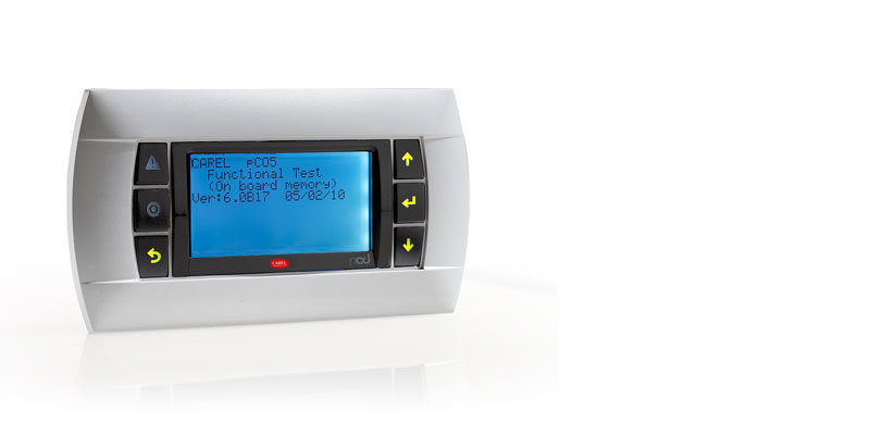
is a monochromatic (blue/white) LCD graphic terminal with 320×240 pixel resolution (code PGD2*******) and LED backlighting.
pGD
pGD
3 3 3 3
pGD
pGD
pGD
pGD
is a 256-colour LCD graphic terminal with 320×240 pixel resolution (code PGD3*******) and CCFL fluorescent backlighting.
Version
Version
Version
Version
Panel installation
Wall-mounting
Panel installation
Wall-mounting
3.1.3
3.1.3
PGD0000F00 terminal (built- — — — in/panel)/PGD0000W00 pCO graphic display (wall)
PGD0000F00 terminal (built
3.1.3
3.1.3
PGD0000F00 terminal (built
PGD0000F00 terminal (built
Fig. 3.a
Fig. 3.a
Fig. 3.a
Fig. 3.a
Code: +030220336 — rel. 1.5 — 22/12/10
Versio
Version n n n
Versio
Versio
PGD2
PGD2
PGD3
PGD3
in/panel)/PGD0000W00 pCO graphic display (wall)
in/panel)/PGD0000W00 pCO graphic display (wall)
in/panel)/PGD0000W00 pCO graphic display (wall)
Display
Display
Display
Display
Type:
Backlighting:
Graphic resolution:
Text modes:
Character height:
Size of the active area:
Size of the display area:
LEDs on keypad
LEDs on keypad
LEDs on keypad
LEDs on keypad
— 2 programmable by «application program», red and orange (Prg and Alarm buttons);
— 4 green, for backlighting the LCD (↑ ↓ Enter and Esc buttons).
Power supply
Power supply
Power supply
Power supply
Voltage: power supply from pCO via telephone connector or from external source
18/30 Vdc protected by 250 mAT external fuse.
Maximum power input: 0.8 W.
PGD
PGD
PGD
PGD
PGD0
PGD0000F00
PGD0
PGD0000W00
PGD1
PGD1000F00
PGD1
PGD1000W00
PGD1
PGD1000FW0
PGD1
PGD1000FX0
PGD1
PGD1000WW0
PGD1
PGD1000WX0
PGD0
PGD0000I00
PGD1
PGD1000I00
PGD1
PGD1000IW0
PGD
PGD
Model codes
Model codes
PGD
PGD
Model codes
Model codes
PGD200*F0*
PGD200*W0*
PGD300*F0*
PGD300*W0*
FSTN graphic
green LEDs (managed by «application program»)
120×32 pixels
4 rows x 20 columns (5×7 and 11×15 pixel fonts)
2 rows x 10 columns (11×15 pixel fonts)
or mixed modes
4.5 mm (5×7 pixel fonts)
9 mm (11×15 pixel fonts)
71.95×20.75 mm
76×25.2 mm
27
Model codes
Model codes
Model codes
Model codes
Instruction sheet
Instruction sheet
Instruction sheet
Instruction sheet
+050001040
+050001050
+050001050
+050001050
+050001045
+050001055
Instruction sheet
Instruction sheet
Instruction sheet
Instruction sheet
+050001041
pCO Sistema
Tab. 3.a
Tab. 3.a
Tab. 3.a
Tab. 3.a
Tab. 3.b
Tab. 3.b
Tab. 3.b
Tab. 3.b