инструкцияCarel SmartCella

High Efficiency Solutions
SmartCella
NO POWE
& SIGNAL
CABLES
TOGETHE
READ CAREFULLY IN THE TEXT!
Электронный контроллер
Руководство пользователя
Посмотреть инструкция для Carel SmartCella бесплатно. Руководство относится к категории без категории, 1 человек(а) дали ему среднюю оценку 8.5. Руководство доступно на следующих языках: русский. У вас есть вопрос о Carel SmartCella или вам нужна помощь? Задайте свой вопрос здесь
Нужна помощь?
У вас есть вопрос о Carel а ответа нет в руководстве? Задайте свой вопрос здесь Дай исчерпывающее описание проблемы и четко задайте свой вопрос. Чем детальнее описание проблемы или вопроса, тем легче будет другим пользователям Carel предоставить вам исчерпывающий ответ.
Количество вопросов: 0

Главная
Не можете найти ответ на свой вопрос в руководстве? Вы можете найти ответ на свой вопрос ниже, в разделе часто задаваемых вопросов о Carel SmartCella.
Инструкция Carel SmartCella доступно в русский?
Не нашли свой вопрос? Задайте свой вопрос здесь
-
Contents
-
Table of Contents
-
Bookmarks
Quick Links
SmartCella/SmartCella 3PH
Electronic controllers for cold rooms
User manual
NO POWER
& SIGNAL
CABLES
TOGETHER
READ CAREFULLY IN THE TEXT!
H i g h
E f f i c i e n c y
S o l u t i o n s
Related Manuals for Carel SmartCella 3PH
Summary of Contents for Carel SmartCella 3PH
-
Page 1
SmartCella/SmartCella 3PH Electronic controllers for cold rooms User manual NO POWER & SIGNAL CABLES TOGETHER READ CAREFULLY IN THE TEXT! H i g h E f f i c i e n c y S o l u t i o n s… -
Page 3
The technical specifi cations shown in the manual may be changed without prior warning. The liability of CAREL in relation to its products is specifi ed in the CAREL general contract conditions, available on the website www.CAREL.com and/or by specifi c agreements with customers;… -
Page 5: Table Of Contents
Content 1. INTRODUCTION 9. TECHNICAL SPECIFICATIONS Main features …………………..7 Technical specifi cations ………………42 Accessories ……………………8 SmartCella 3PH wiring diagrams …………..44 Connections for pump down operation managed 2. INSTALLATION by Smartcella ………………….48 Dimensions (mm) ………………..9 10. APPENDIX 1: VPM (VISUAL PARAMETER Wall mounting ………………….9…
-
Page 7: Introduction
(stopping the compressor), heater, hot gas; • advanced defrost functions; Fig. 1.a • automatic recognition of the network protocol: Carel or Modbus®; • parameter selection simplifi ed by diff erent icons according to the Single-phase version part numbers category;…
-
Page 8: Accessories
Description WP00B47B20 Smartcella 3PH 7.5HP 6.3-10A motor protector 3PH 9kW defrost 3PH 2kW evaporator fans 1PH 800W condenser fans 1PH 800W light WP00B57B20 Smartcella 3PH 7.5HP 10-16A motor protector 3PH 9kW defrost 3PH 2kW evaporator fans 1PH 800W condenser fans 1PH 800W light Tab.
-
Page 9: Installation
2. INSTALLATION 2.1 Dimensions (mm) 2.2 Wall mounting Single-phase version Single-phase version 47,5 Ø32 47,5 Remove the faceplates (1 and 2) and unscrew the screws to open the control Fig. 2.a Three-phase version Release fl at connector to remove frontal panel a.
-
Page 10: Wiring Diagram
Arm the circuit breakers and the motor protector Three-phase version Close the front panel using the six screws Layouts and components Power the panel on (WP00B34A10, WP00B24A10, WP00B14A10) Arm the main switch (yellow/red) Warning • separate the power cables (power supply, loads) from the signal cables (probes, digital inputs) and the serial cable •…
-
Page 11
Code Description Smartcella Power light Evaporator light Compressor light Alarm light Defrost light Evaporator fan contactor Compressor contactor Defrost heater contactor Alarm relay Evaporator/condenser fan/defrost heater circuit breaker Auxiliary circuit breaker Compressor motor protector Main disconnect switch Auxiliary terminal block Power terminal block Terminal block WP00B44A10, WP00B34A10, WP00B24A10, WP00B14A10… -
Page 12
Code WP00B57B20, WP00B47B20 Terminal block XP1 Terminal block XA1 Fig. 2.i Terminal block Number Description Type Terminal block Number Description Type LP pressure switch Input Evaporator fan Output Valve Output Condenser fan Output Fan thermal protector Input Safety thermostat Input Defrost heaters Output Inside lights… -
Page 13: Installation
2.4 Installation 2.5 Programming key IROPZKEY00/A0 To install the controller, proceed as follows, with reference to the wiring The programming key can load up to 7 diff erent parameter confi gurations diagrams shown in the previous paragraphs: onto the controller (the controller operating parameters plus 6 sets connect the probes and power supply: the probes can be installed up of customisable default parameters).
-
Page 14: Remote Display Connection
The system allows a maximum of 207 units, with a maximum length of 1000 m. Connection requires the standard accessories (RS485- USB converter, CAREL P/N CVSTDUMOR0) and a 120 Ω terminating resistor to be installed on the terminals of the last connected controller. Connect the RS485 converter to the controllers and make the connections as shown in the fi…
-
Page 15: User Interface
3. USER INTERFACE The front panel contains the display and the keypad, made up of 4 buttons that, when pressed alone or combined with other buttons, are used to program the controller. The optional remote display is used to display the temperature measured by a second probe. 3.1 Display The user terminal display shows temperature in range -50 to +150°C.The temperature is displayed with resolution to the tenths between –19.9…
-
Page 16: Signal Leds
3.3 Signal LEDs Icon Colour Function Status Notes Green POWER Auxiliary circuit powered Auxiliary circuit not powered LED on depending on the status (ON) of circuit breaker QF2 and disconnect switch QS1 Yellow COMPRESSOR Power available at compressor No power at compressor power LED on depending on the status (ON) of motor power terminals terminals…
-
Page 17
Power up the controller holding the Prg/mute button, until the • the code of parameter d/1 is displayed fl ashing; message “Std” or “Bn0“ (on SmartCella 3PH) are shown on the display, • continue holding the buttons until the value measured by the defrost after 5 s. -
Page 18
3.4.12 Minimum and maximum temperature monitoring The controller can record the minimum and maximum temperature measured by the control probe over a period of up to 999 hours (more than 41 days). To enable monitoring: • enter programming mode as explained in the corresponding paragraph;… -
Page 19: Commissioning
4. COMMISSIONING 4.1 Confi guration Example: in the case of bottle coolers, typically used in supermarkets where the doors are opened frequently, due to the greater thermal The confi guration parameters are set when commissioning the controller, inertia of the liquids compared to the air (and the fact that the probe and involve: is positioned in the air and not directly on the products), the controller •…
-
Page 20: Loading The Sets Of Parameters
Functions that can be disabled on the keypad 4.2 Loading the sets of parameters Up to 6 sets of custom parameters can be selected on the controller, after Important: if setting H2 ≠ 1, 3, the type F parameters cannot be set, having been loaded using the VPM programming tool (Visual Parameter but rather only their values can be displayed.
-
Page 21: Functions
5. FUNCTIONS 5.1 Probes (analogue inputs) Par. Description Def Min Max UOM /A3 Probe 3 confi guration (S3) The SmartCella platform controllers feature a maximum of 5 analogue inputs, which are used for NTC, high temperature NTC (NTC Enhanced 0 Digital input 1 (DI1) 1 Product (display only) Range) or PTC temperature sensors (see the note below).
-
Page 22
The following parameters are involved in the explanation of the settings 3 = Enable defrost for A4, A5 and A9. Application: any defrosts called when the contact is open remain pending until the contact closes. The various possibilities are shown below. Par. -
Page 23
Case 1: light off when opening the door Note: If the door is opened with the light OFF: • if the light was previously switched on manually, when the door is • the compressor and the evaporator fans are switched off ; closed for the second time, it is automatically switched off… -
Page 24
9 = Door switch with fan off only CMP/FAN CMP/FAN DI OPEN DI CLOSED Same as for option “A4”=5, with the diff erence being that when opening the door only the evaporator fan is switched off . 10 = Direct/reverse operation Important: when A4 = 10, the status of digital input has priority DIRECT Fig. -
Page 25: Digital Outputs
• 12 = Auxiliary output c0: when the controller is powered on, the compressor, evaporator Set H1 and/or H5 = 2 to activate the auxiliary output. fans and auxiliary relay in neutral zone control (‘H1’=11) are started after a delay (in minutes) equal to the value assigned to this parameter. See the table at the start of this paragraph for details on the activation/ The delay is used to protect the compressor against repeated starts in deactivation logic.
-
Page 26: Control
6. CONTROL Switching the controller On/Off 6.3 Set point The controller can be switched ON/OFF from a number of sources; The reference output is the compressor output (CMP). keypad, supervisor and digital input. In this operating mode, the display The controller can operate in 3 diff erent modes, as selected by parameter will be show the temperature selected for parameter /tI, alternating with •…
-
Page 27: Pump Down
r3=0,1 CMP Compressor Low pressure switch Condenser Filter-drier Liquid receiver Evaporator Thermostatic expansion valve Liquid gauge PDV Pump down valve Pump down can be selected: • by pressure (pressure switch required): when the pump down valve rn/2 rn/2 closes, the compressor continues operating until the pressure switch measures the defi…
-
Page 28: Continuous Cycle
6.7 Anti-sweat heater CMP, When the unit is powered on, the compressor is activated in cooling mode and the AUX and light outputs are disabled until the control probe measures a value less than St + Hdh. The aim is to prevent the light or the heater connected to the AUX output from adding heat and contrasting the work done by the compressor.
-
Page 29: Defrost
Par. Description Def Min Max UOM Par. Description Def Min Max UOM Output switched with scheduler d0 Type of defrost 0 = Heater by temperature 0 = Light; 1= AUX 1 = Hot gas by temperature Set point variation with scheduler 2 = Heater by time (Ed1, Ed2 not shown) 0/1 = no/yes 3 = Hot gas by time (Ed1, Ed2 not shown)
-
Page 30
1. Heater defrost (d0 = 0, 2, 4): duty cycle Note: the defrost output (DEF) is used to control the hot gas valve V_def. The duty cycle refers to the default values of parameters F2 and F3. REFRIG PUMP DRIP POST REFRIG DOWN… -
Page 31: Evaporator Fans
6.10 Evaporator fans Note: The evaporator fans can be managed according to the temperature • if dI expires when the controller is OFF, a defrost will be performed measured by the defrost and control probes. The deactivation threshold when next switched on; is equal to the value of parameter F1, and the hysteresis is equal to the •…
-
Page 32: Condenser Fans
6.12 Duty setting (par. c4) Par. Description Def Min Max UOM dd Dripping time after defrost (fans off ) If alarm “rE” (virtual control probe fault) is activated, this parameter is F2 Evaporator fans with compressor off used to ensure operation of the compressor until the fault is resolved. 0 = See F0 As the compressor is no longer able to operate based according to the 1 = Always off…
-
Page 33: Parameter Table
7. PARAMETER TABLE Models U-M. Type Min. Max. Def. Symbol Code Parameter Password WE00S%, WE00C% e WP% Measurement stability WE00S%, WE00C% e WP% Probe display stability WE00S%, WE00C% e WP% Virtual probe composition WE00S%, WE00C% e WP% Temperature unit of measure (0: °C ,1: °F) WE00S%, WE00C% e WP% fl…
-
Page 34
Models U-M. Type Min. Max. Def. Symbol Code Parameter Typo of defrost WE00S%, WE00C% e WP% fl ag 0: Electric heater by temperature 1: Hot gas by temperature 2: Electric heater by time (Ed1, Ed2 not shown) 3: Hot gas by time (Ed1, Ed2 not shown) 4: Electric heater by time with temperature control (Ed1, Ed2 not shown) MAximum time between consecutive defrosts… -
Page 35
Models U-M. Type Min. Max. Def. Symbol Code Parameter Evaporator fan management WE00C% e WP% fl ag 0: always on 1: Activation based on Sd-Sv ( diff erence between virtual probe and evaporator temperature) 2: Activation based on Sd (evaporator temperature) Fan activation temperature (only if F0= 1 or 2) WE00C% e WP% °C/°F… -
Page 36: Variables Only Accessible Via Serial Connection
Minute min. Tab. 7.a 7.14 Variables only accessible via serial connection Description Type CAREL SVP Modbus Virtual probe Probe 1 reading Probe 2 reading Probe 3 reading Probe 4 reading Number of parameter sets available Digital input 1 status…
-
Page 37: Signals And Alarms
8. SIGNALS AND ALARMS 8.1 Signals 8.3 Reset alarms Signals are messages shown on the display to notify the user of the All the alarms with manual reset can be cleared by pressing Prg/mute and control procedures in progress (e.g. defrost) or confi rm the controls from UP together for more than 5 seconds.
-
Page 38
To display the HA and HF alarms: • enter the HACCP menu by pressing • scroll the list of alarms by pressing UP and DOWN; • press Set to select the required alarm (HA, HA1, HA2/HF, HF1, HF2); • use UP or DOWN to see the description of the alarm: year, month, day, hours, minutes and duration in minutes of the selected alarm;… -
Page 39
“SmartCella manual” +0300084EN — rel. 1.2 — 28.03.2017… -
Page 40: Alarm Parameters
8.5 Alarm parameters 8.6 HACCP alarm parameters and monitoring Alarm parameters and activation AAL (AH) is used to determine the activation threshold for the low (high) HA alarms temperature alarm LO (HI). The value set for AL (AH) is continuously The alarm queue can be displayed by accessing parameters HA to compared against the value measured by the control probe.
-
Page 41: High Condenser Temperature Alarm
8.8 Frost protection alarm The frost protection alarm is only active if a probe has been set as the frost protection probe. If this probe measures a temperature less than the threshold ALF for a time greater than AdF, the alarm “AFr” (manual reset) is shown.
-
Page 42: Technical Specifications
Probe type 10 kΩ a 25 °C, range –50T90 °C Std. Carel NTC measurement 1 °C in the range -50T50 °C 3 °C in the range 50T90 °C error: 50 kΩ…
-
Page 43
Three-phase version Specifi cations WP00B14A10 WP00B24A10 WP00B34A10 WP00B44A10 WP00B47B20 WP00B57B20 Power supply 400V 3~ +N+E 50/60Hz Max compressor power 5.5HP 7.5HP Protectors Power Disconnect switch Evaporator, condenser and Circuit defrost protection breaker Compressor protection Adjustable motor 1.6-2.5A 2.5-4A 4-6.3A 6.3-10A 10-16A protector Auxiliary circuit protection Circuit… -
Page 44: Smartcella 3Ph Wiring Diagrams
9.2 SmartCella 3PH wiring diagrams 9.2.1 Power circuit WP00B44A10, WP00B34A10, WP00B24A10, WP00B14A10) Fig. 9.a “SmartCella manual” +0300084EN — rel. 1.2 — 28.03.2017…
-
Page 45
9.2.2 Power circuit WP00B57B20, WP00B47B20) Fig. 9.b “SmartCella manual” +0300084EN — rel. 1.2 — 28.03.2017… -
Page 46
9.2.3 Auxiliary circuit Fig. 9.c “SmartCella manual” +0300084EN — rel. 1.2 — 28.03.2017… -
Page 47
Fig. 9.d “SmartCella manual” +0300084EN — rel. 1.2 — 28.03.2017… -
Page 48: Connections For Pump Down Operation Managed By Smartcella
(KM2) remains on until the pressure switch measures low pressure (terminals 101-102) Fig. 9.h Note: do not enable pump down on Smartcella 3PH (check that c7=0, H1≠5). Fig. 9.f Note: as the pressure switch is connected to terminals 101-102, do not enable pump down on Smartcella 3PH (check that c7=0, H1≠5).
-
Page 49
(terminals 110-111, AUX1 output on Smartcella) opens, while the compressor (KM2) operates for the time defi ned by parameter C7 Fig. 9.j Note: do not enable pump down on Smartcella 3PH (check that c7=0, H1≠5). Fig. 9.l “SmartCella manual” +0300084EN — rel. 1.2 — 28.03.2017… -
Page 50: Appendix 1: Vpm (Visual Parameter Manager)
10. APPENDIX 1: VPM (VISUAL PARAMETER MANAGER) • 10.1 Installation Select the key connection port using the guided procedure (Wizard); Go to http://ksa.carel.com and select the following path: Software & Support Confi guration & Updating Softwares Parametric controller software then select Visual Parametric Manager.
-
Page 51: Modify A Parameter
At the end, the list of parameters read is displayed. Note: • on the controller, Set0, Set1, …, Set6 are named bn0 to bn6 respectively; • Set0 is the default set on the controller, i.e. the default confi guration. When loading a diff erent set (Set1…Set6), Set0 is overwritten with the new set and is consequently erased.
-
Page 52: Appendix 2: Advanced Functions
11. APPENDIX 2: ADVANCED FUNCTIONS This algorithm is used to determine whether the shorter duration of a Possible operating sequence (for example, if d12 = 2): defrost allows subsequent defrosts to be skipped. To enable the function, Start count Skip count Current count Defrost Outcome set d12 = 2 or 3.
-
Page 53: Defrost With 2 Evaporators
DEFROST BY TEMPERATURE 11.9 Defrost with 2 evaporators Defrost probe / evap. Situation Eff ect Up to 3 defrost probes and up to 2 evaporator outputs can be confi gured. output confi g. The controller recognises the basic confi guration shown in the table Probe 2 defrost output 1 No probe Defrost ends by timeout below (probe 1 is the control probe and cannot be confi…
-
Page 54
EXAMPLE 3 REQ1 REQ2 rd/2 rd/2 Fig. 11.c Virtual probe Compressor 2 CP1 Compressor 1 Diff erential time Set point Examples of operation: Fig. 11.f EXAMPLE 1 EXAMPLE 4 REQ1 REQ1 REQ2 REQ2 Fig. 11.d Fig. 11.g EXAMPLE 2 REQ1 compressor 1 call compressor 1 REQ1… -
Page 56
Agenzia / Agency: CAREL INDUSTRIES S.p.A. Via dell’Industria, 11 — 35020 Brugine — Padova (Italy) Tel. (+39) 049.9716611 — Fax (+39) 049.9716600 e-mail: carel@carel.com — www.carel.com…
WE00*
Общие характеристики
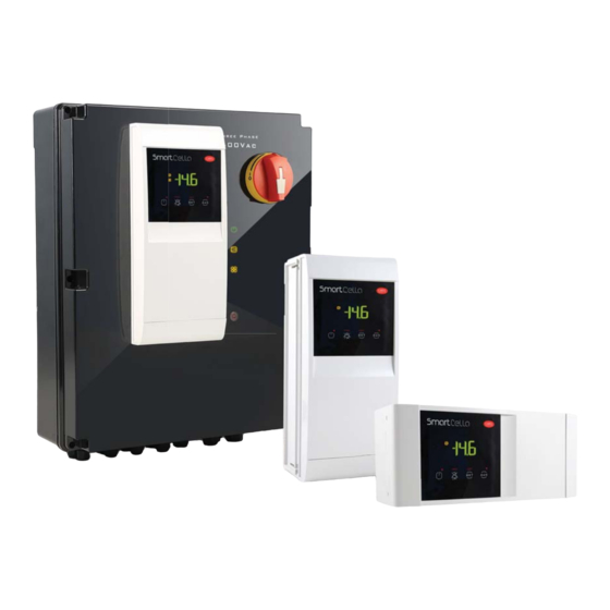
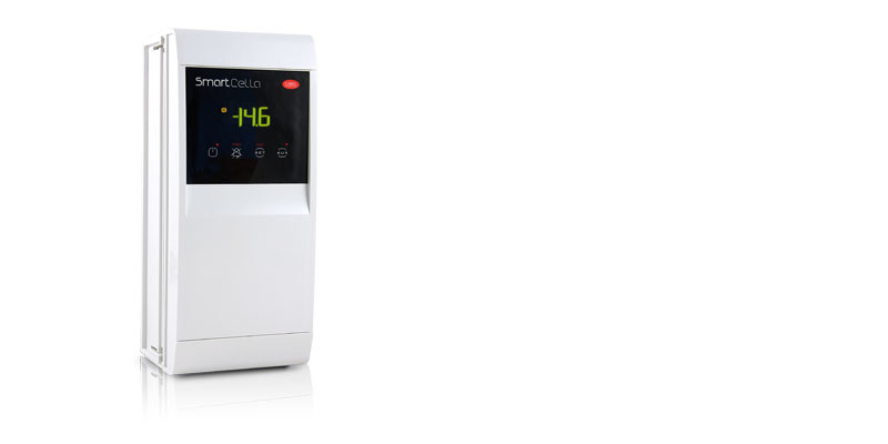
В основе контроллера SmartCella лежит стандартный электронный контроллер, размещенный в корпусе класса защиты IP65. Данный контроллер дополняет контроллеры серий UltraCella и MasterCella от компании CAREL, предназначенные для управления морозильными камерами. У моделей разные коды, но только у двух моделей отличия заключаются напрямую в количестве подключаемых нагрузок, поддерживаемых датчиках и функциях, необходимых для управления морозильными камерами: модель с 1 релейным выходом для управления среднетемпературными морозильными камерами и модель с 4 релейными выходами для управления низкотемпературными морозильными камерами.
Входы и выходы:
- до 4 релейных выходов (выход управления компрессорами 16A/2лс в зависимости от модели, оттайкой 16A, вентиляторами испарителя 8A и дополнительный выход 8A для дополнительных функций)
- 5 аналоговых входов (2 x NTC + 3 x NTC / цифровые входы)
- 1 последовательный порт с поддержкой и автоматическим распознаванием протоколов CAREL / Modbus (ведомый)
- Контроллеры SmartCella удовлетворяют всем требованиям по управлению морозильными камерами на всех этапах: от момента установки и электромонтажа до ввода в эксплуатацию и дальнейшей каждодневной работы
На этапе установки для специалистов по монтажу:
- Быстрый и простой монтаж на DIN-рейку
- Плата ввода/вывода контроллера ir33 под монтаж на DIN-рейку удобней для установки внутри электрощитка, чем стандартный контроллер
- Стандартная и привычная схема электрического монтажа контроллера ir33 под монтаж на DIN-рейке
- Контроллер SmartCella легко вводится в эксплуатацию и далее используется в каждодневной работе:
- Такой же, как у контроллера ir33+ принцип регулирования, алгоритмы управления, параметры и навигация
- Простое и удобное управление тачпадом и крупными кнопками. Функциональное назначение кнопок такое же, как у контроллера ir33+
Большой и яркий дисплей (на 30% больше и ярче дисплея контроллера ir33), в процессе навигации по которому показываются подсказки.
Возможности контроллера SmartCella легко наращиваются установкой дополнительных устройств, которые прекрасно помещаются в корпусе UltraCella. Кроме класса защиты IP65 и единообразного внешнего вида со всеми контроллерами семейства UltraCella, корпус предусматривает возможность установки внутри следующих устройств:
- внешние реле
- контакторы
- дополнительные клеммы
и другие дополнительные внешние модули семейства UltraCella:
- модуль привода Ultra EVD
- модуль питания Ultra Power
Контроллеры SmartCella соответствуют всем международным требованиям стандарта ХАССП, устанавливающего требования по безопасности пищевых продуктов, и это первый пример подобного электронного устройства в Италии, предназначенного для применения в составе холодильного оборудования, что только подтверждает идеальную пригодность такого контроллера для гарантированной сохранности пищевых продуктов.
Преимущества
- Современный вариант на базе контроллера ir33+
- Простое и удобное управление
- Корпус класса защиты IP65 с возможностью установки дополнительных компонентов
- Поддержка и автоматическое распознавание протоколов Modbus и Carel
- Быстрый и простой монтаж на DIN-рейку
Документация
Technical
-
2D/3D модели
Код Описание Язык Дата * Выпуск Код
2d-3d SmartCellaОписание
2D-3D drawingsЯзык
ALLДата
10/11/2015
Выпуск
R0
-
Инструкции по применению
Код Описание Язык Дата * Выпуск Код
+0300084FRОписание
SmartCella/SmartCella 3PH
Contrôle électronique pour chambres froidesЯзык
FREДата
24/09/2020
Выпуск
1.3
Код
+0300084DEОписание
SmartCella/SmartCella 3PH
Elektronische Steuergeräte für KühlräumeЯзык
GERДата
24/09/2020
Выпуск
1.3
Код
+0300084ENОписание
SmartCella/SmartCella 3PH
Electronic controllers for cold roomsЯзык
ENGДата
24/09/2020
Выпуск
1.3
Код
+0300084ITОписание
SmartCella/SmartCella 3PH
Controlli elettronici per celle frigorifereЯзык
ITAДата
24/09/2020
Выпуск
1.3
Код
+0300084ESОписание
SmartCella/SmartCella 3PH
Controladores electrónicos para cámaras frigoríficasЯзык
SPAДата
24/09/2020
Выпуск
1.3
Код
+0300084RUОписание
SmartCella
Электронный контроллерЯзык
RUSДата
05/02/2015
Выпуск
1.1
-
Руководства по эксплуатации
Код Описание Язык Дата * Выпуск Код
+0500091IEОписание
SmartCella — Controllo elettronico per celle frigorifere/Electronic controller for cold roomsЯзык
ENG
ITAДата
20/05/2020
Выпуск
1.4
Код
+0500090MLОписание
SmartCella — Controllo elettronico per celle frigorifere/Electronic controller for cold roomsЯзык
ENG
FRE
GER
ITA
POR
SPAДата
20/05/2020
Выпуск
1.3
Код
+0500091FDОписание
SmartCella — Commande électroniques pour chambres froides / Elektronische Steuerung für KühlräumeЯзык
FRE
GERДата
20/05/2020
Выпуск
1.4
Commercial
-
Other related documentation
Код Описание Язык Дата * Выпуск Код
+3000192ITОписание
Cella Range
Soluzioni per celle frigorifereЯзык
ITAДата
02/10/2019
Выпуск
2.0
Код
+3000192ENОписание
Cella Range
Solutions for cold roomsЯзык
ENGДата
02/10/2019
Выпуск
2.0
Код
+3000192DEОписание
Cella Range Lösungen für KühlräumeЯзык
GERДата
02/10/2019
Выпуск
2.0
Код
+3000192ESОписание
Cella Range Soluciones para cámaras frigoríficasЯзык
SPAДата
02/10/2019
Выпуск
2.0
-
Брошюра
Код Описание Язык Дата * Выпуск Код
+3000192PLОписание
Linia Cella Rozwiązania dla chłodniЯзык
POLДата
02/10/2019
Выпуск
2.0
Код
+3000088DEОписание
SmartCella
Die unabdingbare Lösung für Ihre kleinen KühlräumeЯзык
GERДата
24/07/2014
Выпуск
1.0
Код
+3000088ENОписание
SmartCella
The essential solution for your small cold roomsЯзык
ENGДата
24/07/2014
Выпуск
1.0
Код
+3000088ITОписание
SmartCella
La soluzione essenziale per le tue piccole celle frigorifereЯзык
ITAДата
24/07/2014
Выпуск
1.0
Код
+30Z0088ENОписание
SmartCella The essential solution for your small cold roomsЯзык
ENGДата
24/07/2014
Выпуск
1.0
Код
+3000088PTОписание
SmartCella — A solução essencial para as suas pequenas celasЯзык
PORДата
24/07/2014
Выпуск
1.0
Код
+3000088RUОписание
SmartCellaЯзык
RUSДата
27/04/2014
Выпуск
1.0
-
История успеха
Код Описание Язык Дата * Выпуск Код
+4000057NLОписание
Energiebesparing in koelcellenЯзык
DUTДата
20/04/2017
Выпуск
1.0
Код
+4000057ENОписание
Energy savings in cold roomsЯзык
ENGДата
20/04/2017
Выпуск
1.0
Код
+4000057ITОписание
Risparmio energetico nelle celle frigoЯзык
ITAДата
20/04/2017
Выпуск
1.0
Код
+4000057DEОписание
Energie sparen bei KühlräumenЯзык
GERДата
20/04/2017
Выпуск
1.0
Код
+4000057FRОписание
Économie d’énergie dans les cellules frigorifiquesЯзык
FREДата
20/04/2017
Выпуск
1.0
Код
+4000057ESОписание
Ahorro energético en las cámaras frigoríficasЯзык
SPAДата
20/04/2017
Выпуск
1.0
Images
-
High resolution images
Код Описание Язык Дата * Выпуск Код
PH14LWE301-smartcellaОписание
CAREL-Refrigeration Parametric Controls-Cella Range-SmartCellaЯзык
ALLДата
21/09/2021
Выпуск
R.0
- Холодильное оборудование
- Контроллеры


| Артикул | WE00C2HN00 |
| id товара | 8270 |
| Страна | Италия  |
| Минимальный заказ | 1 шт |
| В наличии на складах | 0 шт |
Общее описание
Контроллер SmartCella WE00C2HN00 производства Carel — это однофазный электрощит управления для низкотемпературных холодильных камер на базе контроллера Carel ir33+.Имеет 4 релейных выхода (для управления компрессором (16А), оттайкой испарителя(16А), вентиляторами воздухоохладителя (8А), и дополнительный выход 8A для дополнительных функций).5 аналоговых входов (2 x NTC + 3 x NTC / цифровые входы). 1 последовательный порт с поддержкой и автоматическим распознаванием протоколов CAREL / Modbus (ведомый). Возможности контроллера SmartCella легко наращиваются установкой дополнительных устройств, которые прекрасно помещаются в корпусе UltraCella. Кроме класса защиты IP65 и единообразного внешнего вида со всеми контроллерами семейства UltraCella, корпус предусматривает возможность установки внутри следующих устройств: внешние реле контакторы, дополнительные клеммы и другие дополнительные внешние модули семейства UltraCella: модуль привода Ultra EVD, модуль питания Ultra Power.
SmartCella контроллер Carel — это модель из серии «Серия Cella». Компания «Стандарт Климат» — официальный дилер Carel в России. Мы осуществляем поставку, монтаж и сервисное обслуживание оборудования Carel.
Доставка по Москве — бесплатная. Оплата возможна наличным или безналичным расчетом, банковской картой.
«Стандарт Климат» готова реализовать комплексное решение любой вашей задачи по инженерному оборудованию «под ключ». Скидку до 20% на оборудование Carel мы обсуждаем индивидуально.
Звоните:
+7 (499) 350-94-14
. Как получить коммерческое предложение?
Описание
В основе контроллера SmartCella лежит стандартный электронный контроллер, размещенный в корпусе класса защиты IP65. Данный контроллер дополняет контроллеры серий UltraCella и MasterCella от компании CAREL, предназначенные для управления морозильными камерами. У моделей разные коды, но только у двух моделей отличия заключаются напрямую в количестве подключаемых нагрузок, поддерживаемых датчиках и функциях, необходимых для управления морозильными камерами: модель с 1 релейным выходом для управления среднетемпературными морозильными камерами и модель с 4 релейными выходами для управления низкотемпературными морозильными камерами.
Входы и выходы:
- до 4 релейных выходов (выход управления компрессорами 16A/2лс в зависимости от модели, оттайкой 16A, вентиляторами испарителя 8A и дополнительный выход 8A для дополнительных функций)
- 5 аналоговых входов (2 x NTC + 3 x NTC / цифровые входы)
- 1 последовательный порт с поддержкой и автоматическим распознаванием протоколов CAREL / Modbus (ведомый)
- Контроллеры SmartCella удовлетворяют всем требованиям по управлению морозильными камерами на всех этапах: от момента установки и электромонтажа до ввода в эксплуатацию и дальнейшей каждодневной работы
На этапе установки для специалистов по монтажу:
- Быстрый и простой монтаж на DIN-рейку
- Плата ввода/вывода контроллера ir33 под монтаж на DIN-рейку удобней для установки внутри электрощитка, чем стандартный контроллер
- Стандартная и привычная схема электрического монтажа контроллера ir33 под монтаж на DIN-рейке
- Контроллер SmartCella легко вводится в эксплуатацию и далее используется в каждодневной работе:
- Такой же, как у контроллера ir33+ принцип регулирования, алгоритмы управления, параметры и навигация
- Простое и удобное управление тачпадом и крупными кнопками. Функциональное назначение кнопок такое же, как у контроллера ir33+
Большой и яркий дисплей (на 30% больше и ярче дисплея контроллера ir33), в процессе навигации по которому показываются подсказки.
Возможности контроллера SmartCella легко наращиваются установкой дополнительных устройств, которые прекрасно помещаются в корпусе UltraCella. Кроме класса защиты IP65 и единообразного внешнего вида со всеми контроллерами семейства UltraCella, корпус предусматривает возможность установки внутри следующих устройств:
- внешние реле
- контакторы
- дополнительные клеммы
и другие дополнительные внешние модули семейства UltraCella:
- модуль привода Ultra EVD
- модуль питания Ultra Power
Контроллеры SmartCella соответствуют всем международным требованиям стандарта ХАССП, устанавливающего требования по безопасности пищевых продуктов, и это первый пример подобного электронного устройства в Италии, предназначенного для применения в составе холодильного оборудования, что только подтверждает идеальную пригодность такого контроллера для гарантированной сохранности пищевых продуктов.
Преимущества
- Современный вариант на базе контроллера ir33+
- Простое и удобное управление
- Корпус класса защиты IP65 с возможностью установки дополнительных компонентов
- Поддержка и автоматическое распознавание протоколов Modbus и Carel
- Быстрый и простой монтаж на DIN-рейку
О производителе Carel

Оборудование CAREL для увлажнения воздуха получило признание во всем мире. Увлажнители компании установлены в музеях, где они помогают защитить бесценные произведения искусства; в цехах по производству мобильных телефонов и компьютеров, где требуются особые условия влажности; в банках и медицинских центрах, разбросанных по всему миру. Производители вина и пищевых продуктов используют увлажнители CAREL для обеспечения качества своей продукции. Системы увлажнения воздуха CAREL можно увидеть в цехах по производству машин массового спроса и гоночных автомобилей Формулы 1. Ведущие самолетостроительные компании устанавливают увлажнители CAREL в самых современных летательных аппаратах.
Для работы в жилых и офисных помещениях компанией CAREL разработаны увлажнители серии homeSteam. Созданные с учетом последних достижений в этой области, увлажнители homeSteam отличаются простотой монтажа и эксплуатации, высокой надежностью работы.
Отправьте заявку и получите КП
Подберем оборудование, удешевим смету, проверим проект, доставим и смонтируем в срок.