Americas Headquarters
Cisco Systems, Inc.
170 West Tasman Drive
San Jose, CA 95134-1706
USA
http://www.cisco.com
Tel:
408 526-4000
800 553-NETS (6387)
Fax: 408 527-0883
Cisco, Cisco Systems, the Cisco logo, and the Cisco Systems logo are registered trademarks or trademarks of Cisco Systems, Inc. and/or its affiliates in the
United States and certain other countries. All other trademarks mentioned in this document or Website are the property of their respective owners. The use of the
word partner does not imply a partnership relationship between Cisco and any other company. (0705R)
© 2011 Cisco Systems, Inc. All rights reserved.
78-19956-01
Cisco IP PTZ Dome Camera Models
CIVS-IPC-2911, CIVS-IPC-2916, CIVS-IPC-2930,
CIVS-IPC-2935
Q
UICK
S
TART
G
UIDE
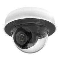
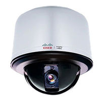
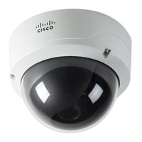
Поворотная видеокамера Cisco CIVS-IPC-2935 имеет CCD-матрицу EXview HAD компании Sony, WDR 128x и подвижный ИК-фильтр для работы в режимах «день/ночь». Cisco 2935 обеспечивает одну или двухпотоковую трансляцию видео в форматах H.264, MPEG-4 и M-JPEG с разрешением D1 при 25 к/с, поддерживает двунаправленную аудиосвязь и электронную стабилизацию изображения.
В отличие от другой поворотной модели Cisco серии 2900, которая предназначена для установки внутри помещений на любой потолок, включая навесные и фальшпотолки, купольная IP-видеокамера Cisco 2935 выпускается в уличном исполнении и рассчитана на подвесной монтаж на кронштейн. У обеих моделей серии имеется ряд общих ключевых характеристик, в дополнение к которым поворотная видеокамера 2935 имеет еще несколько показателей, среди которых мощный 35-кратный трансфокатор и функция электронной стабилизации и улучшения видеоизображения. Кроме того, за счет наличия кожуха с IP66, обогревателем, вентилятором и солнцезащитным козырьком, уличная модель эффективно работает в широком температурном диапазоне и в сложных условиях видеонаблюдения.
Cisco 2935 оптимально подходит для видеонаблюдения на больших по площади объектах и позволяет заменить несколько неподвижных видеокамер, поскольку использует высокоскоростное поворотное устройство с диапазоном углов поворота/наклона до 360°/+2º — -92º и точностью позиционирования ±0,1°. Для постоянного видеомониторинга объекта поворотная видеокамера предусматривает программирование до 256 пресетов и 8 туров автопатрулирования. При переходе по предустановкам скорость панорамирования видеокамеры может достигать 400°/с, а наклона – 200°/с, тогда как в ручном режиме управления эти показатели составляют 80°/с и 40°/с, соответственно.
В отличие от многих уличных видеокамер, Cisco 2935 может работать в более широком диапазоне внешних температур от -51° до +60°С и поддерживает функцию электронной стабилизации изображения, которая компенсирует «дрожание» видео при вибрациях корпуса, вызванных, например, порывами ветра или проезжающим автотранспортом. Кроме того, эта поворотная видеокамера оснащена аудио- входом/выходом для подключения внешнего микрофона и динамика, и позволяет организовать двунаправленную аудиосвязь с объектом видеонаблюдения в режиме полу- или полный дуплекс, используя для сжатия звука кодек G.711.
Осуществлять видеонаблюдение за удаленными объектами позволяет мощный 35-кратный трансфокатор с автофокусировкой, которым оснащены новые видеокамеры Cisco. Диапазон фокусных расстояний трансфокатора составляет 3,4 – 119 мм, а угол обзора варьируется от 55,8 до 1,7. При этом оптическое увеличение может быть дополнено 12-кратным цифровым зумом, за счет чего поворотная видеокамера обеспечивает общее увеличение до 420-крат. Более того, эта поворотная модель имеет расширенный динамический диапазон х128 и соотношение «сигнал-шум» 50 дБ, благодаря которым она формирует более детализированное изображение объектов в режиме цифрового увеличения изображения.
Способность передавать как аналоговый, так и цифровой видеосигнал отличает новые поворотные камеры от многих аналогов. В качестве чувствительного элемента Cisco 2935 использует 1/4-дюймовую CCD-матрицу Sony EXview HAD с возможностью выбора чересстрочной либо прогрессивной развертки, поэтому может транслировать аналоговое изображение с разрешением 540 ТВЛ или 1/2 потока цифрового видео с разрешением до 704х576 пикс. и фреймрейтом до 25 к/с в форматах H.264, MPEG-4 и M-JPEG. Кроме того, каждая поворотная видеокамера серии оснащена отключаемым ИК-фильтром и способна передавать цветное/монохромное видео при минимальных освещенностях 0,015/0,00015 лк, а также поддерживает функцию LowLight для компенсации недостаточной освещенности сцены наблюдения.
Выполнять настройку рабочих параметров новой видеокамеры и ее последующее администрирование можно локально или удаленно с ПК через веб-браузер Internet Explorer 8.0 или средствами специализированного программного обеспечения. Каждая поворотная видеокамера 2935-серии имеет встроенное ПО с открытой архитектурой, совместима с системой Cisco Video Surveillance Manager (VMS) и программным обеспечением таких производителей, как Lenel, Pelco, Milestone и др. Для управления поворотным механизмом Cisco 2935 поддерживают протоколы телеметрии Coaxitron, Pelco D и Pelco P.
Функциональные особенности камеры Cisco CIVS-IPC-2935:
Поддержка электронной стабилизации изображения
Скорость электронного затвора Cisco CIVS-IPC-2935 можно настраивать в пределах 1/1,5-1/30 000 с, что позволяет изменять время экспозиции видеокамеры в зависимости от условий освещенности и скорости ее поворота, также и вручную. Отличительная особенность этой уличной модели – поддержка функции электронной стабилизации изображения, при помощи которой поворотная видеокамера обеспечивает формирование четкого и чистого изображения без эффекта «дрожания» даже при постоянных вибрациях и порывах ветра. Тем самым, купольные IP-видеокамеры Cisco CIVS-IPC-2935 оптимально подходят для видеонаблюдения за дорожным движением, например, на автомагистралях.
Три видеокодека и два потока Real time видео
Сетевые видеокамеры Cisco серии 2900 поддерживают три алгоритма видеосжатия – передовой H.264, а также MPEG-4 и M-JPEG, и обеспечивают двухпотоковую передачу видео по сети. Независимо от выбранного алгоритма сжатия, Cisco 2935 позволяет сконфигурировать видеопотоки с различным разрешением, частотой кадров, битрейтом и структурой GOP (Group of Pictures). В процессе инсталляции поворотная видеокамера предоставляет оператору возможность настроить параметры первого потока произвольно, например, установить максимальное разрешение D1 (704х576) и фреймрейт – 25 к/с, а параметры второго потока скорректировать в зависимости от первого.
Аудиоканал, тревожный интерфейс и охранные функции Cisco 2935
Уличная IP-видеокамера «день-ночь» этой серии оснащена аудио- входом и выходом, использует аудиокодек G.711 и позволяет оператору центра мониторинга не только видеть все происходящее в секторе ее обзора (в том числе, управляя поворотным устройством), но и общаться с находящимися там людьми при подключении внешнего микрофона и динамика. Наряду с этим, поворотная видеокамера оснащена видеодетектором движения и имеет 7 тревожных входов и 2 выхода, которые предназначены для подключения внешних охранных датчиков и исполнительных устройств охранной системы.
Администрирование видеокамеры средствами ПО Cisco VSM
Наглядное экранное меню Cisco 2935 позволяет инсталлятору легко настроить параметры ее работы, например, через веб-браузер Internet Explorer. Удаленно управлять потоками видео, программировать предустановленные позиции наклонно-поворотного устройства IP-видеокамеры и др. можно не только с веб-браузера, но и при помощи программного обеспечения компании Cisco для сетевых систем видеонаблюдения – Video Surveillance Manager (CVSM). Это программное обеспечение предоставляет оператору все функции управления видеосистемой, в частности, просмотра «живого» видео, которое передает поворотная видеокамера, записи и поиска видеоданных в архиве и др. Если Cisco 2935 будет работать в составе видеосистемы, включающей охранное оборудование различных марок, она может быть интегрирована в ПО других известных разработчиков.
- Единица измерения: 1 шт
- Габариты (мм): 293x293x5
- Масса (кг): 2935.00
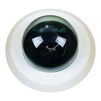
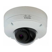
Комплект Cisco CIVS-IPC-2935 – набор для уличной поворотной камеры, используемый для круглосуточного визуального контроля за территориями. Модель поддерживает цветной и черно-белый режимы съемки, способна функционировать в условиях низкой освещенности. Оптический зум позволяет приближать изображение в 35 раз, за счет чего удается получать не только общие планы, но и отдельные детали.
Фокусное расстояние объектива составляет 3.4-119 мм, а максимальное разрешение кадра равняется 704х576 пикселей. Прозрачный купол защищает оборудование от попадания жидкости, ветра и механических ударов. Модель выдерживает перепады температур, способна работать в 50-градусный мороз.
| Артикул | 159603 |
| Гарантия | 12 месяцев. |
| Страна производства | Китай |
| Инструкция | В комплекте. |
| Сертификат | Посмотреть |
Технические характеристики:
- Поддерживаемые видеокодеки: H.264, MJPEG, MPEG-4
- Поддерживаемые аудиокодеки: G.711/PCM 8-bit, 8 KHz mono 64 kbit/s
- Порт Ethernet:10/100 Мбит/с
- Тип установки: Настенное/потолочное
- Тип питания: AC 18-32В/DC 22-27В
- Гарантия: 90 дней Cisco Limited Warranty
- Блок питания в комплекте: Нет
- Потребляемая мощность номинальная/максимальная: 23/73 Ватт (с подогревом)
* Информация о технических характеристиках, комплекте поставки, стране изготовления, внешнем виде и цвете товара в
интернет-магазине Борн носит справочный характер и основывается на последних доступных к моменту публикации сведениях.
Overview
The Cisco video surveillance encoders, models CIVS-SENC-4P and CIVS-SENC-8P, convert analog video into high quality digital video, and set a new standard in encoder security. The CIVS-SENC-4P and CIVS-SENC-8P models contain the following key features:
•![]() Allow 4-CH or 8-CH high resolution video capture with a high frame rate.
Allow 4-CH or 8-CH high resolution video capture with a high frame rate.
•![]() Use the H.264 compression format, resulting in greatly reduced video file sizes, and conserving valuable bandwidth and storage space.
Use the H.264 compression format, resulting in greatly reduced video file sizes, and conserving valuable bandwidth and storage space.
•![]() The 4 port model, CIVS-SENC-4P, supports simultaneous dual streams, while the 8 port model, CIVS-SENC-8P, supports single stream to be transmitted in H.264, MPEG-4, and MJPEG formats. The video stream can also be individually configured with frame rates, resolution, and image quality to meet different platforms or bandwidth constraints.
The 4 port model, CIVS-SENC-4P, supports simultaneous dual streams, while the 8 port model, CIVS-SENC-8P, supports single stream to be transmitted in H.264, MPEG-4, and MJPEG formats. The video stream can also be individually configured with frame rates, resolution, and image quality to meet different platforms or bandwidth constraints.
•![]() Use motion detection.
Use motion detection.
•![]() Upgrade the security level of the associated IP surveillance system with the HTTPS network security protocol.
Upgrade the security level of the associated IP surveillance system with the HTTPS network security protocol.
•![]() Compatible with Cisco Video Surveillance Manager Version 6.3.2 and later software, providing scalability and easy-to-use operation.
Compatible with Cisco Video Surveillance Manager Version 6.3.2 and later software, providing scalability and easy-to-use operation.
•![]() Designed as a rack mount solution for easy installation. (Needs optional accessory kit.)
Designed as a rack mount solution for easy installation. (Needs optional accessory kit.)
These features make the CIVS-SENC-4P and CIVS-SENC-8P models easy to install and integrate with an existing analog camera. As a highly innovative video encoder series, the CIVS-SENC-4P and CIVS-SENC-8P models allow you to easily upgrade to a full-featured, high-end, IP surveillance solution.
Read Before Use
It is important to verify that all contents received are complete according to the package contents list (see the «Package Contents» section). Take note of the warnings in the Quick Start Guide before installing the encoder; then carefully read and follow the instructions in the Network Deployment section of this guide (see the «Network Deployment» section) to avoid damage during installation.
The encoder is a network device, and it is designed for various applications, including video sharing, general security/surveillance, and so on. The Configuration chapter (see the «Configuration» section) suggests ways to make best use of the encoder, and to ensure proper operation.
Package Contents
The Cisco video surveillance encoder package includes these items:
•![]() CIVS-SENC-4P (4 channel) or CIVS-SENC-8P (8 channel) encoder (qty. 1)
CIVS-SENC-4P (4 channel) or CIVS-SENC-8P (8 channel) encoder (qty. 1)
•![]() Power adapter (qty. 1)
Power adapter (qty. 1)
•![]() General I/O terminal blocks for CIVS-SENC-4P (10 pins x 3 pieces) or CIVS-SENC-8P (16 pins x 3 pieces) (qty. 3)
General I/O terminal blocks for CIVS-SENC-4P (10 pins x 3 pieces) or CIVS-SENC-8P (16 pins x 3 pieces) (qty. 3)
•![]() Warranty card (qty. 1)
Warranty card (qty. 1)
Physical Description
CIVS-SENC-4P Front and Back View
Figure 1-1 shows the front view of the CIVS-SENC-4P encoder. The top row is comprised of four video input slots, and the bottom row is comprised of four audio input slots.
Figure 1-1 CIVS-SENC-4P Front View

|
|
BNC video inputs (qty. 4) |
|
|
RCA audio inputs (qty. 4) |
Figure 1-2 shows the back view of the CIVS-SENC-4P encoder.
Figure 1-2 CIVS-SENC-4P Back View

|
|
BNC video inputs (qty. 4) |
|
|
RCA audio inputs (qty. 4) |
Figure 1-2 shows the back view of the CIVS-SENC-4P encoder.
Figure 1-2 CIVS-SENC-4P Back View
|
|
Ethernet 10/100/1000 RJ45 port |
|
SD/SDHC card slot. While the SD/SDHC slot is on the device, it is not currently supported by Cisco. |
|
|
In encoders that support USB, press this button before removing the USB device. |
|
In encoders that support SD/SDHC, press this button before removing the SD/SDHC device. |
|
|
Status LEDs. For more information, see the «Status LED» section. |
|
Reset button (recessed). For more information, see the «Hardware Reset» section. |
|
|
USB port. While the USB port is on the device, it is not currently supported by Cisco. |
|
Power input |
|
|
General I/O terminal block. For more information, see the «General I/O Terminal Block» section. |

Note ![]() Where enabled, the USB port is for maintenance purposes only.
Where enabled, the USB port is for maintenance purposes only.
CIVS-SENC-8P Front and Back View
Figure 1-3 shows the front view of the CIVS-SENC-8P encoder. The top row is comprised of eight video input slots, and the bottom row is comprised of eight audio input slots.
Figure 1-3 CIVS-SENC-8P Front View

|
|
BNC video inputs (qty. |
|
|
RCA audio inputs (qty. |

Figure 1-4 shows the back view of the CIVS-SENC-8P encoder.
Figure 1-4 CIVS-SENC-8P Back View

|
|
BNC video inputs (qty. |
|
|
RCA audio inputs (qty. |
Figure 1-4 shows the back view of the CIVS-SENC-8P encoder.
Figure 1-4 CIVS-SENC-8P Back View
|
|
Ethernet 10/100/1000 RJ45 port |
|
SD/SDHC card slot. While the SD/SDHC slot is on the device, it is not currently supported by Cisco. |
|
|
In encoders that support USB, press this button before removing the USB device. |
|
In encoders that support SD/SDHC, press this button before removing the SD/SDHC device. |
|
|
Status LEDs. For more information, see the «Status LED» section. |
|
Reset button (recessed). For more information, see «Hardware Reset» section. |
|
|
USB port. While the USB port is on the device, it is not currently supported by Cisco. |
|
Power input |
|
|
General I/O terminal block. For more information, see «General I/O Terminal Block» section. |
Note ![]() Where enabled, the USB port is for maintenance purposes only.
Where enabled, the USB port is for maintenance purposes only.
General I/O Terminal Block
This encoder provides a general I/O terminal block which is used to connect external input /output devices. For information about the pin definitions, see the «Pin Definitions of the General I/O Terminal Blocks» section.
Pin Definitions of the General I/O Terminal Blocks
Figure 1-5 shows the pin locations on the back panel of the CIVS-SENC-4P encoder, and Table 1-1 provides definitions for each of the pins.l
Figure 1-5 CIVS-SENC-4P Pin Locations

|
GND |
N/A |
CH 4 GND |
CH 4 DI |
CH 3 GND |
CH 3 DI |
CH 2 GND |
CH 2 DI |
CH 1 GND |
CH 1 DI |
|
GND |
N/A |
CH 4 GND |
CH 4 DO |
CH 3 GND |
CH 3 DO |
CH 2 GND |
CH 2 DO |
CH 1 GND |
CH 1 DO |
|
CH 4 Audio out |
CH 3 Audio out |
CH 2 Audio out |
CH 1 Audio out |
RS 485- |
RS 485+ |
24V AC |
24V AC |
GND |
DC 12V |
Figure 1-6 shows the pin locations on the back panel of the CIVS-SENC-8P encoder, and Table 1-2 provides definitions for each of the pins.
Figure 1-6 CIVS-SENC-8P Pin Locations

|
GND |
N/A |
CH 4 GND |
CH 4 DI |
CH 3 GND |
CH 3 DI |
CH 2 GND |
CH 2 DI |
CH 1 GND |
CH 1 DI |
|
GND |
N/A |
CH 4 GND |
CH 4 DO |
CH 3 GND |
CH 3 DO |
CH 2 GND |
CH 2 DO |
CH 1 GND |
CH 1 DO |
|
CH 4 Audio out |
CH 3 Audio out |
CH 2 Audio out |
CH 1 Audio out |
RS 485- |
RS 485+ |
24V AC |
24V AC |
GND |
DC 12V |
Figure 1-6 shows the pin locations on the back panel of the CIVS-SENC-8P encoder, and Table 1-2 provides definitions for each of the pins.
Figure 1-6 CIVS-SENC-8P Pin Locations
|
CH 8 GND |
CH 8 DI |
CH 7 GND |
CH 7 DI |
CH 6 GND |
CH 6 DI |
CH 5 GND |
CH 5 DI |
CH 4 GND |
CH 4 DI |
CH 3 GND |
CH 3 DI |
CH 2 GND |
CH 2 DI |
CH 1 GND |
CH 1 DI |
|
CH 8 GND |
CH 8 DO |
CH 7 GND |
CH 7 DO |
CH 6 GND |
CH 6 DO |
CH 5 GND |
CH 5 DO |
CH 4 GND |
CH 4 DO |
CH 3 GND |
CH 3 DO |
CH 2 GND |
CH 2 DO |
CH 1 GND |
CH 1 DO |
|
GND |
GND |
CH 8 Audio out |
CH 7 Audio out |
CH 6 Audio out |
CH 5 Audio out |
CH 4 Audio out |
CH 3 Audio out |
CH 2 Audio out |
CH 1 Audio out |
RS 485- |
RS 485+ |
24V AC |
24V AC |
GND |
DC 12V |
DI/DO Diagram
Figure 1-7 shows the connections necessary to set up the encoder with various external devices.
Figure 1-7 DI/DO Connections

Note ![]()
Note ![]() The following guidelines should be observed:
The following guidelines should be observed:
•![]() External alarms or other devices that connect to the digital outputs require an external power supply, for example, DC power from a power adapter.
External alarms or other devices that connect to the digital outputs require an external power supply, for example, DC power from a power adapter.
•![]() 12V Ground should connect to the encoder ground terminal block. For detailed pin definitions, see the «Pin Definitions of the General I/O Terminal Blocks» section.
12V Ground should connect to the encoder ground terminal block. For detailed pin definitions, see the «Pin Definitions of the General I/O Terminal Blocks» section.
•![]() It is recommended that you keep the current running through each of the DO lines under 1A.
It is recommended that you keep the current running through each of the DO lines under 1A.
Status LED
The LED indicates the status of the encoder. Table 1-3 describes the different status levels of the Yellow (SD), Green (Network), and Red (Power) LEDs.
|
|
|
|
|---|---|---|
|
SD |
Steady yellow |
SD card is present and functioning normally |
|
Blinking yellow |
SD card is present yet problems occurred with data access |
|
|
Yellow LED off |
No SD card in the slot |
|
|
Network |
Blinking green every 1 sec. |
Network activity (heartbeat) |
|
Green LED off |
Network failed |
|
|
Power |
Steady red |
Power on and during system boot |
|
Red LED off |
Power off |
Table 1-4 describes LED blinking states.
|
|
|
|---|---|
|
Blinking green every 2 sec. |
Audio mute (heartbeat) |
|
Blinking red every 0.15 sec. and blinking green every 1 sec. |
Upgrading firmware |
|
Blinking red every 0.15 sec. and blinking green every 0.15 sec. |
Restoring default |
Hardware Reset
See Figure 1-2 (CIVS-SENC-4P) or Figure 1-4 (CIVS-SENC-8P) for the location of the hardware reset button on your encoder. The reset button is used to reset the system or to restore the factory default settings. Sometimes, if your encoder is experiencing a problem, resetting the system can return the encoder to normal operation. If, after performing a reset, the problem remains, restore the factory settings and install the system again.
Use one of the following methods to reset or restore the settings:
•![]() Reset—Press and release the recessed reset button using a straightened paper clip. Wait for the encoder to reboot.
Reset—Press and release the recessed reset button using a straightened paper clip. Wait for the encoder to reboot.
•![]() Restore—Press and hold the reset button down until the status LED blinks rapidly. It takes about 30 seconds. Note that all settings are restored to factory default. When the system has been restored successfully, the status LED blinks green and red during normal operation.
Restore—Press and hold the reset button down until the status LED blinks rapidly. It takes about 30 seconds. Note that all settings are restored to factory default. When the system has been restored successfully, the status LED blinks green and red during normal operation.
Network Deployment
Setting up the Encoder on the Network
To connect the encoder to the camera and the network, follow these steps:
Procedure
Step 1 ![]() Connect the video out slot on the camera to a BNC video input slot on the encoder. See Figure 1-8.
Connect the video out slot on the camera to a BNC video input slot on the encoder. See Figure 1-8.
Step 2 ![]() Connect the line-out audio source on the camera to an RCA audio input slot on the encoder.
Connect the line-out audio source on the camera to an RCA audio input slot on the encoder.
Figure 1-8 Video and Audio Connections

Step 3 ![]()
Step 3 ![]() Connect the encoder to a switch using an Ethernet cable. See Figure 1-9.
Connect the encoder to a switch using an Ethernet cable. See Figure 1-9.
Step 4 ![]() Connect the encoder to a power outlet using the power cable.
Connect the encoder to a power outlet using the power cable.
Step 5 ![]() If you have external devices, such as sensors or alarms, connect them to the general I/O terminal block. For detailed pin definitions, see the «Pin Definitions of the General I/O Terminal Blocks» section.
If you have external devices, such as sensors or alarms, connect them to the general I/O terminal block. For detailed pin definitions, see the «Pin Definitions of the General I/O Terminal Blocks» section.
Figure 1-9 Network, Power, and External Device Connections

Step 6 ![]()
Step 6 ![]() You can set up the encoder on the network in any of the following ways:
You can set up the encoder on the network in any of the following ways:
•![]() Set up the encoder behind a router. For more information, see the «Setting up the Encoder Behind a Router» section.
Set up the encoder behind a router. For more information, see the «Setting up the Encoder Behind a Router» section.
•![]() Use a static IP address. For more information, see the «Setting up the Encoder Using a Static IP Address» section.
Use a static IP address. For more information, see the «Setting up the Encoder Using a Static IP Address» section.
•![]() Use PPPoE. For more information, see the «Ready to Use» section.
Use PPPoE. For more information, see the «Ready to Use» section.
Setting up the Encoder Behind a Router
To set up the encoder behind a router, perform the following procedure:
Before you begin
•![]() Make sure you have a router.
Make sure you have a router.
•![]() Find out the public IP address of your router provided by your ISP (Internet Service Provider).
Find out the public IP address of your router provided by your ISP (Internet Service Provider).
Procedure
Step 1 ![]() Connect your encoder behind a router. For information on how to obtain your IP address, see the «Accessing the Encoder» section.
Connect your encoder behind a router. For information on how to obtain your IP address, see the «Accessing the Encoder» section.
Step 2 ![]() In this case, if the Local Area Network (LAN) IP address of your encoder is 192.168.0.3, forward the following ports for the encoder on the router:
In this case, if the Local Area Network (LAN) IP address of your encoder is 192.168.0.3, forward the following ports for the encoder on the router:
•![]() HTTP port
HTTP port
•![]() RTSP port
RTSP port
•![]() RTP port for audio
RTP port for audio
•![]() RTCP port for audio
RTCP port for audio
•![]() RTP port for video
RTP port for video
•![]() RTCP port for video
RTCP port for video
If you have changed the port numbers on the Network window, open the ports accordingly on your router. For information on how to forward ports on the router, refer to the user manual for your router.
Step 3 ![]() Use the public IP address of your router and the secondary HTTP port to access the encoder from the Internet. For more information, see the «Network Type Settings» section.
Use the public IP address of your router and the secondary HTTP port to access the encoder from the Internet. For more information, see the «Network Type Settings» section.
Setting up the Encoder Using a Static IP Address
Choose this connection type if you are required to use a static IP address for the encoder. For more information, see the «LAN Settings» section.
Enabling Authentication
Cisco recommends that you use the following procedure to enable authentication on the encoder via its Web-based user interface.
Procedure
Step 1 ![]() On the home window of the encoder user interface, choose Configuration > Security.
On the home window of the encoder user interface, choose Configuration > Security.
For more information about accessing the encoder user interface, see the «Accessing the Encoder» section.
Step 2 ![]() Set a root password and then confirm it.
Set a root password and then confirm it.
Note ![]() These encoders allow up to 20 user accounts plus the root account. The default passwords are blank for both users and the root. For user names and all passwords, the minimum length is one character and the maximum length allowed is 64 characters. The root, user names, and their passwords can include the following characters: a-z, A-Z, 0-9, !, $, %, -, . , ^, _, ~, @
These encoders allow up to 20 user accounts plus the root account. The default passwords are blank for both users and the root. For user names and all passwords, the minimum length is one character and the maximum length allowed is 64 characters. The root, user names, and their passwords can include the following characters: a-z, A-Z, 0-9, !, $, %, -, . , ^, _, ~, @
Step 3 ![]() In the Manage Privilege area, ensure that the Allow Anonymous Viewing checkbox is unchecked.
In the Manage Privilege area, ensure that the Allow Anonymous Viewing checkbox is unchecked.
Step 4 ![]() Click Save.
Click Save.
Step 5 ![]() Click HTTPS in the left-hand pane, ensure that the Enable HTTPS secure connection checkbox is unchecked, and click Save.
Click HTTPS in the left-hand pane, ensure that the Enable HTTPS secure connection checkbox is unchecked, and click Save.
HTTPS is not supported by VSM.
Step 6 ![]() Click Network in the left-hand pane and do the following:
Click Network in the left-hand pane and do the following:
•![]() In the HTTP area, choose Basic on the Authentication drop-down menu, and ensure that the HTTP port is 80.
In the HTTP area, choose Basic on the Authentication drop-down menu, and ensure that the HTTP port is 80.
•![]() In the RTSP Streaming area, choose Basic on the Authentication drop-down menu. The digest mode is not supported.
In the RTSP Streaming area, choose Basic on the Authentication drop-down menu. The digest mode is not supported.
•![]() Click Save.
Click Save.
Note ![]() The credentials you set up here should also be used when the encoder is added in Video Surveillance Manager Server (VSMS) and Video Surveillance Operations Manager (VSOM).
The credentials you set up here should also be used when the encoder is added in Video Surveillance Manager Server (VSMS) and Video Surveillance Operations Manager (VSOM).
Ready to Use
When you have completed setup, you are ready to access the encoder. For more information, see the «Accessing the Encoder» section.
- Manuals
- Brands
- Cisco Manuals
- Security Camera
ManualsLib has more than 55 Cisco Security Camera manuals
Click on an alphabet below to see the full list of models starting with that letter:
2
3
4
5
6
7
8
C
M
N
P
S
T
V
W
Popular manuals
82 pages
4300 User Manual

66 pages
WVC80N User Manual
2 pages
WVC210 Quick Start Manual
19 pages
Meraki MV32 Installation Manual
147 pages
PVC2300 Administration Manual

8 pages
WVC80N Quick Installation Manual
85 pages
WVC210 — Small Business Wireless-G PTZ Internet Video Camera Administration Manual

88 pages
8020 Reference Manual

8 pages
Meraki MV12 Installation Manual
7 pages
Meraki MV12 Installation Manual
85 pages
WVC210 Reference Manual
2 pages
CIVS-IPC-2911 Quick Start Manual
2 pages
CIVS-IPC-2521V Quick Start Manual

32 pages
TelePresence MX700 Installation Manual
13 pages
5010 Quick Start Manual
108 pages
VC 220 Administration Manual
4 pages
CIVS-IPC-5010 User Manual
90 pages
CIVS-IPC-2611 User Manual
48 pages
6020 Installation Manual
100 pages
8620 Reference Manual
Models
Document Type
2
253 Series

Quick Start Manual
2600 Series
Manual • Installation Manual • Release Notes • Manual • Manual • Configuration • Hardware Installation Manual • Configuration Manual • Software Configuration Manual • Hardware Installation Manual • Hardware Installation Manual • Application Note • Safety Information Manual • Datasheet • Quick Reference Manual • Quick Reference Manual • Appendix • Hardware Installation Manual • Operation Manual • Installation Manual • Overview • Quick Start Manual • Manual • Getting Started Manual
2630 IP
Datasheet
2630V
Datasheet
2830
Installation Manual
2835
Installation Manual
3
3530
Product Overview • Installation Manual
3630
Installation Manual
4
4300
User Manual
4300E
User Manual
5
5011
Datasheet • Quick Start Manual • User Manual
6
6020
Product Overview • Installation Manual
6930
Installation Manual
7
7030E
Datasheet
8
8020
Reference Manual
8030
Reference Manual
8620
Reference Manual
8630
Reference Manual
C
Catalyst 4500 Series
Solution Manual • Installation Note • Installation Manual • Frequently Asked Questions Manual • Description • Datasheet • Supplementary Manual • Release Notes • Supplementary Manual • Datasheet • Manual • Software Manual • Switch Manual • Command Reference Manual • System Message Manual • Datasheet • User Manual • Installation Manual • Command Reference Manual • Quick Reference Manual • Overview • Reference Manual • Message Manual • Command Reference Manual • Installation Manual • Configuration Manual • Administration Manual • Configuration Manual • Software Configuration Manual • Replacement Manual • Manual • Upgrade Manual
Catalyst 4500e Series
User Manual • Installation Manual
CIVS-IPC-2520V
Quick Start Manual
CIVS-IPC-2521V
Quick Start Manual
CIVS-IPC-2530V
Quick Start Manual
CIVS-IPC-2531V
Quick Start Manual
CIVS-IPC-2600
User Manual • Quick Start Manual
CIVS-IPC-2611
User Manual
CIVS-IPC-2911
Quick Start Manual
CIVS-IPC-2916
Quick Start Manual
CIVS-IPC-2930
Quick Start Manual
CIVS-IPC-2935
Quick Start Manual
CIVS-IPC-3421V
Quick Start Manual
CIVS-IPC-3520
Quick Start Manual
CIVS-IPC-5010
User Manual
CIVS-IPC-5011
User Manual
M
Meraki MV12
Installation Manual • Installation Manual
Meraki MV21
Installation Manual
Meraki MV32
Installation Manual
Meraki MV63
Installation Manual
Meraki MV93 Series
Installation Manual
N
Nexus 5010
Datasheet • Quick Start Manual • User Manual
P
PTZ
Installation Manual
PVC2300 — Small Business Internet Video Camera
Datasheet • Administration Manual • Reference Manual • Installation And Administration Manual
PVC300 — Small Business Pan Tilt Optical Zoom Internet Camera Network
Administration Manual • Quick Start Manual • Installation And Administration Manual
S
Small Business VC220
Datasheet • Quick Start Manual • Administration Manual • Installation And Administration Manual
Small Business VC240
Quick Start Manual • Datasheet
T
TelePresence MX700
Installation Manual • Quick Start Manual • User Manual • Installation Manual • User Manual • Administrator’s Manual • Installation Manual • Reference Manual • Installation Manual • Reference Manual • Quick Reference Manual • Manual • Manual • Installation Manual • Quick Reference Manual • Quick Reference Manual
V
VC 220
Administration Manual
Video Surveillance 3520
Installation Manual • Datasheet • Quick Start Manual
W
Wireless Service Module 2
Getting Started Manual
WVC200 — Wireless-G PTZ Internet Camera
Administration Manual • Release Note • Datasheet
WVC210 — Small Business Wireless-G PTZ Internet Video Camera
Quick Start Manual • Administration Manual • Administration Manual • Datasheet • Datasheet • Reference Manual
WVC2300 — Small Business Wireless-G Internet Video Camera
Datasheet • Administration Manual • Reference Manual • Installation And Administration Manual
WVC80N
User Manual • Quick Installation Manual