Посетил недавно очередной раз наш местный супермаркет. Когда я проходил мимо отдела с автомобильным барахлом, в глаза бросилась небольшая коробка с зарядным устройством для автомобильных аккумуляторов. Решил присмотреться, что ж за зверь такой. Называется Battery Charger Compact 2500. Взял распечатанный блок и сквозь щели попытался рассмотреть, что у него внутри. На вес зарядное оказалось довольно легким. Внутри просматривался обычный силовой трансформатор и какие-то провода. Так как есть простой трансформатор, то зарядное скорее всего обычный стабилизатор напряжения. Платы видно не было. Больших сглаживающих электролитов тоже.
Цена этого «чудо-прибора» была всего 490 руб! Ну как тут не взять?.. Хотя бы ради корпуса и трансформатора. Считай по себестоимости. Ну и решил я его взять. Особо, конечно на него никаких надежд не возлагал. Кетай — он и в Африке кЕтай. Но то что я увидел внутри — это шок!
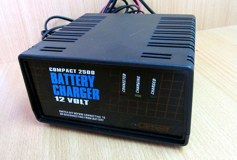
Выглядит эта поделка так:
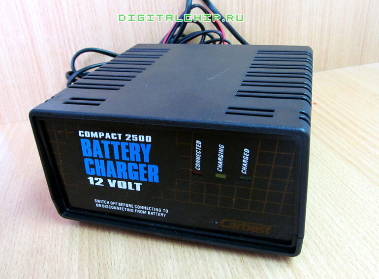
Зарядное устройство для стартерных батарей Compact 2500
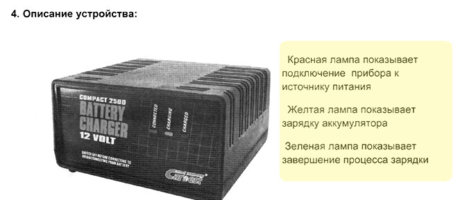
На передней панели размещены три индикатора: «Connected», «Charging», «Charged». И все. Все просто. Но про них дальше.
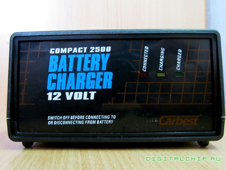
Зарядное устройство для стартерных батарей Compact 2500. Передняя панель.
Сзади зарядник выглядит так:
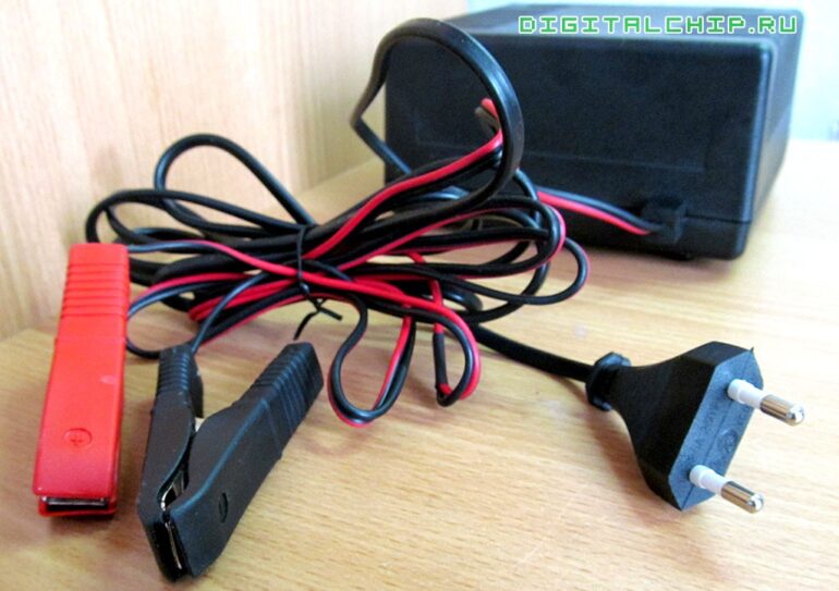
Зарядное устройство для стартерных батарей Compact 2500. Вид сзади.
Все нормально, но провода какие то хиленькие и вилка, ведь обещают зарядный ток 2.5А.
Сверху и по бокам размещены щели вентиляции (через которые я рассматривал внутренности).
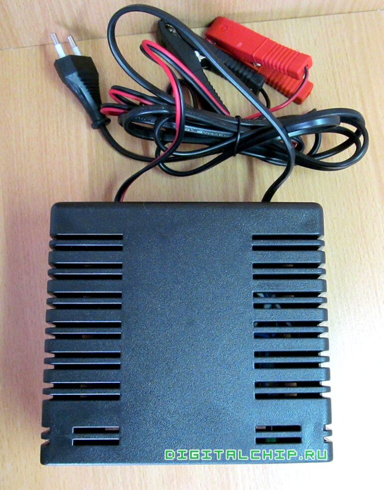
Зарядное устройство для стартерных батарей Compact 2500. Щели вентиляции.
Ладно, вскроем его!
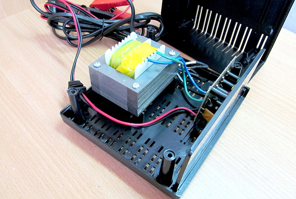
Вот они, внутренности… Да-с-с-с… Чего-то негусто…
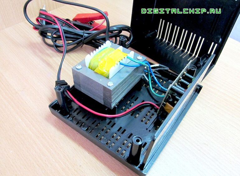
Зарядное устройство для стартерных батарей Compact 2500. Вскрытие.
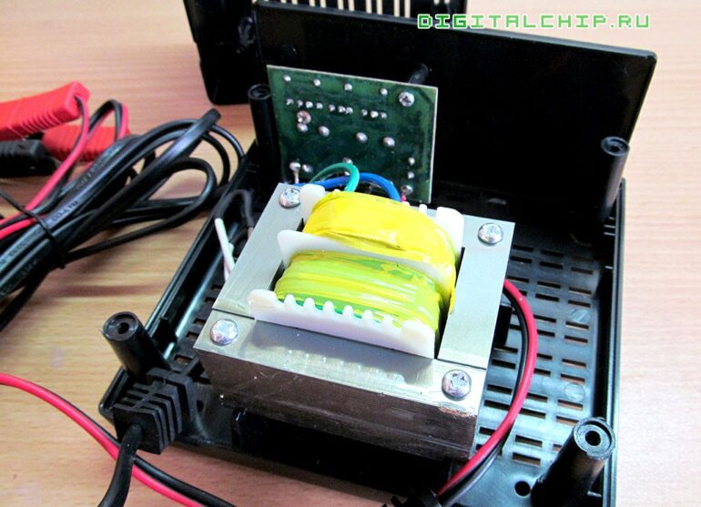
Зарядное устройство для стартерных батарей Compact 2500. Вскрытие. Другой вид.
Да-с-с-с… Но продолжим…
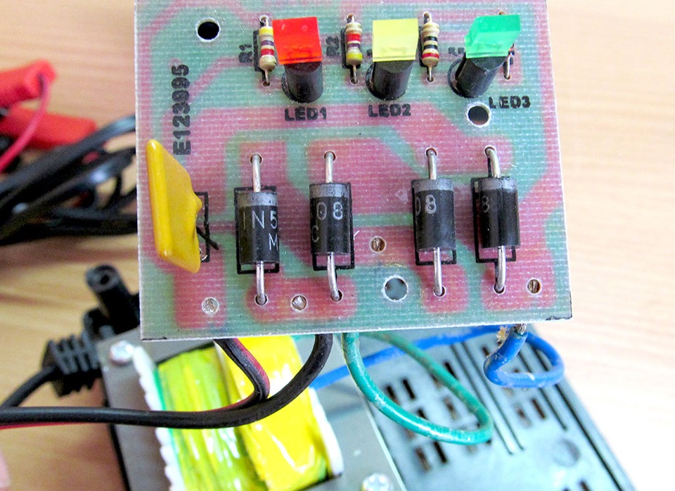
Вся плата в неотмытом флюсе и липкая. Один саморез уже полностью ржавый, на одном коррозия только началась. Провода, которые идут от платы и к трансформатору припаяны прямо к дорожкам. Хотя для них предусмотрены отверстия.
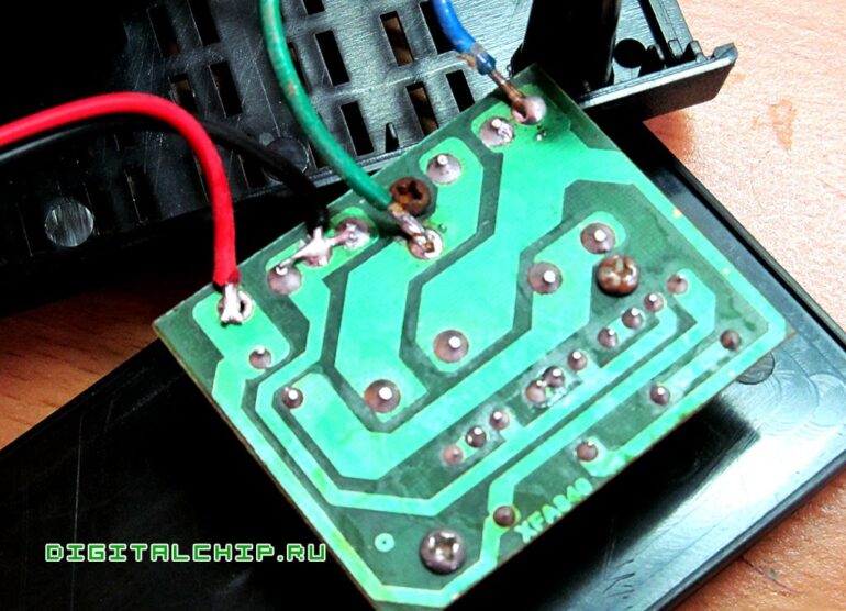
Зарядное устройство для стартерных батарей Compact 2500. Плата зарядника.
Смотрим на плату и офигеваем. Простой диодный мост и все! Даже сглаживающих конденсаторов нет! О каком тут стабилизаторе может идти речь!
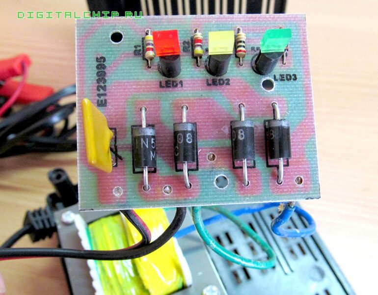
Зарядное устройство для стартерных батарей Compact 2500. Вид на плату.
Вот. Схема всего этого безобразия выглядит так:
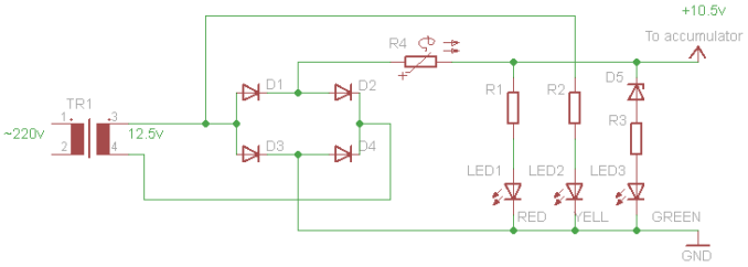
Зарядное устройство для стартерных батарей Compact 2500. Схема.
Как вам? Просто супер интеллектуальная схема! Да…
Кстати, на схеме обозначен терморезистор R4. На самом деле это я ошибся. Это восстанавливающийся предохранитель. Я такие не применял, поэтому по нему ничего не скажу. Выглядит он вот так:

Зарядное устройство для стартерных батарей Compact 2500. Самовосстанавливающийся предохранитель.
Дела…
Но после этого решил еще инструкцию к этому «чуду» почитать. Ржал еще больше. Товарищи «писают в уши» совсем никого не стесняясь. Пишут откровенную лажу. Не поленился и отсканировал инструкцию (скачать можно в конце поста). Выделил места, где поржать можно. Вот например:

Вы вилку видели на фото выше? Какое заземление?..

Почему это мне нельзя вскрывать? Я купил устройство и могу делать с ним что хочу.
А вот характеристики устройства:

Просто интересно, как эта поделка может зарядить 12-вольтовый 80Ач кислотный аккумулятор, если на выходе у него пульсирующее напряжение без нагрузки всего 10 вольт? Если включить нагрузку, так и вообще напряжение очень хорошо просаживается. И насчет максимальных 4 ампер я ой как сильно сомневаюсь… А «защитные устройства» — это, я как понимаю, и есть тот самовосстанавливающийся предохранитель…
Так ли работает индикация как сказано в инструкции?

Если батарею заряжать такой поделкой, то она никогда не зарядится! Никогда! Не надо ля-ля! Завести автомобиль хватит заряда, но не более. Видать товарищи рассчитывают на то, что человек, якобы зарядив батарею, ставит ее в автомобиль, заводит его, и дальше заряд идет уже за счет генератора автомобиль. Пользователь даже и не догадывается, какое же устройство заряжает его аккумулятор.

Про это выше сказал. Насчет 80Ач аккумулятора…

Какое перенапряжение? Вы что? Тут колоссальный недостаток напряжение, а вы про перезаряд…

Какого предохранителя? Плавкого? Так такого в этом «чудо-приборе» не обнаружено…
В инструкции нигде не указан производитель сего девайса. Вообще. Есть только на самом девайсе упоминание, что произведено в Китае по заказу какого-то ООО из Питера. Ни контактов, ни телефонов, ничего.
Ну и так далее. Ржал от души.
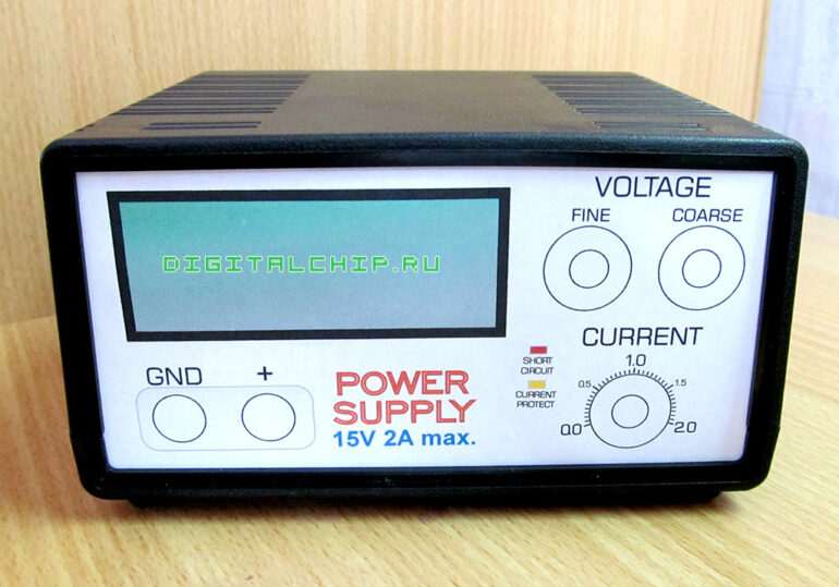
Естественно, я не враг свей батарее и применять по назначению я его ни в коем случае не буду. А вот как источник деталек, а в частности, трансформатора и корпуса, я его использую. Хочу сделать простенький регулируемый блок питания. Примерно вот такой:
Накидайте ссылок или схем, кто в теме по питанию. Буду крайне благодарен.
А за сим откланиваюсь.
Посетил недавно очередной раз наш местный супермаркет. Когда я проходил мимо отдела с автомобильным барахлом, в глаза бросилась небольшая коробка с зарядным устройством для автомобильных аккумуляторов. Решил присмотреться, что ж за зверь такой. Называется Battery Charger Compact 2500. Взял распечатанный блок и сквозь щели попытался рассмотреть, что у него внутри. На вес зарядное оказалось довольно легким. Внутри просматривался обычный силовой трансформатор и какие-то провода. Так как есть простой трансформатор, то зарядное скорее всего обычный стабилизатор напряжения. Платы видно не было. Больших сглаживающих электролитов тоже.
Цена этого «чудо-прибора» была всего 490 руб! Ну как тут не взять? Хотя бы ради корпуса и трансформатора. Считай по себестоимости. Ну и решил я его взять. Особо, конечно на него никаких надежд не возлагал. Кетай — он и в Африке кЕтай. Но то что я увидел внутри — это шок!
Выглядит эта поделка так:
Ладно, вскроем его!
Вот они, внутренности… Да-с-с-с… Чего-то негусто…
Смотрим на плату и офигеваем. Простой диодный мост и все! Даже сглаживающих конденсаторов нет! О каком тут стабилизаторе может идти речь!
Просто интересно, как эта поделка может зарядить 12-вольтовый 80Ач кислотный аккумулятор, если на выходе у него пульсирующее напряжение без нагрузки всего 10 вольт? Если включить нагрузку, так и вообще напряжение очень хорошо просаживается. И насчет максимальных 4 ампер я ой как сильно сомневаюсь…
Если батарею заряжать такой поделкой, то она никогда не зарядится! Никогда! Завести автомобиль хватит заряда, но не более. Видать товарищи рассчитывают на то, что человек, якобы зарядив батарею, ставит ее в автомобиль, заводит его, и дальше заряд идет уже за счет генератора автомобиль. Пользователь даже и не догадывается, какое же устройство заряжает его аккумулятор.
Посетил недавно очередной раз наш местный супермаркет. Когда я проходил мимо отдела с автомобильным барахлом, в глаза бросилась небольшая коробка с зарядным устройством для автомобильных аккумуляторов. Решил присмотреться, что ж за зверь такой. Называется Battery Charger Compact 2500. Взял распечатанный блок и сквозь щели попытался рассмотреть, что у него внутри. На вес зарядное оказалось довольно легким. Внутри просматривался обычный силовой трансформатор и какие-то провода. Так как есть простой трансформатор, то зарядное скорее всего обычный стабилизатор напряжения. Платы видно не было. Больших сглаживающих электролитов тоже.
Цена этого «чудо-прибора» была всего 490 руб! Ну как тут не взять?.. Хотя бы ради корпуса и трансформатора. Считай по себестоимости. Ну и решил я его взять. Особо, конечно на него никаких надежд не возлагал. Кетай — он и в Африке кЕтай. Но то что я увидел внутри — это шок!
Выглядит эта поделка так:
Зарядное устройство для стартерных батарей Compact 2500
На передней панели размещены три индикатора: «Connected», «Charging», «Charged». И все. Все просто. Но про них дальше.
Зарядное устройство для стартерных батарей Compact 2500. Передняя панель.
Сзади зарядник выглядит так:
Зарядное устройство для стартерных батарей Compact 2500. Вид сзади.
Все нормально, но провода какие то хиленькие и вилка, ведь обещают зарядный ток 2.5А.
Сверху и по бокам размещены щели вентиляции (через которые я рассматривал внутренности).
Зарядное устройство для стартерных батарей Compact 2500. Щели вентиляции.
Ладно, вскроем его!
Вот они, внутренности… Да-с-с-с… Чего-то негусто…
Зарядное устройство для стартерных батарей Compact 2500. Вскрытие.
Зарядное устройство для стартерных батарей Compact 2500. Вскрытие. Другой вид.
Да-с-с-с… Но продолжим…
Вся плата в неотмытом флюсе и липкая. Один саморез уже полностью ржавый, на одном коррозия только началась. Провода, которые идут от платы и к трансформатору припаяны прямо к дорожкам. Хотя для них предусмотрены отверстия.
Зарядное устройство для стартерных батарей Compact 2500. Плата зарядника.
Смотрим на плату и офигеваем. Простой диодный мост и все! Даже сглаживающих конденсаторов нет! О каком тут стабилизаторе может идти речь!
Зарядное устройство для стартерных батарей Compact 2500. Вид на плату.
Вот. Схема всего этого безобразия выглядит так:
Зарядное устройство для стартерных батарей Compact 2500. Схема.
Как вам? Просто супер интеллектуальная схема! Да…
Кстати, на схеме обозначен терморезистор R4. На самом деле это я ошибся. Это восстанавливающийся предохранитель. Я такие не применял, поэтому по нему ничего не скажу. Выглядит он вот так:
Зарядное устройство для стартерных батарей Compact 2500. Самовосстанавливающийся предохранитель.
Дела…
Но после этого решил еще инструкцию к этому «чуду» почитать. Ржал еще больше. Товарищи «писают в уши» совсем никого не стесняясь. Пишут откровенную лажу. Не поленился и отсканировал инструкцию (скачать можно в конце поста). Выделил места, где поржать можно. Вот например:
Вы вилку видели на фото выше? Какое заземление?..
Почему это мне нельзя вскрывать? Я купил устройство и могу делать с ним что хочу.
А вот характеристики устройства:
Просто интересно, как эта поделка может зарядить 12-вольтовый 80Ач кислотный аккумулятор, если на выходе у него пульсирующее напряжение без нагрузки всего 10 вольт? Если включить нагрузку, так и вообще напряжение очень хорошо просаживается. И насчет максимальных 4 ампер я ой как сильно сомневаюсь… А «защитные устройства» — это, я как понимаю, и есть тот самовосстанавливающийся предохранитель…
Так ли работает индикация как сказано в инструкции?
Если батарею заряжать такой поделкой, то она никогда не зарядится! Никогда! Не надо ля-ля! Завести автомобиль хватит заряда, но не более. Видать товарищи рассчитывают на то, что человек, якобы зарядив батарею, ставит ее в автомобиль, заводит его, и дальше заряд идет уже за счет генератора автомобиль. Пользователь даже и не догадывается, какое же устройство заряжает его аккумулятор.
Про это выше сказал. Насчет 80Ач аккумулятора…
Какое перенапряжение? Вы что? Тут колоссальный недостаток напряжение, а вы про перезаряд…
Какого предохранителя? Плавкого? Так такого в этом «чудо-приборе» не обнаружено…
В инструкции нигде не указан производитель сего девайса. Вообще. Есть только на самом девайсе упоминание, что произведено в Китае по заказу какого-то ООО из Питера. Ни контактов, ни телефонов, ничего.
Ну и так далее. Ржал от души.
Естественно, я не враг свей батарее и применять по назначению я его ни в коем случае не буду. А вот как источник деталек, а в частности, трансформатора и корпуса, я его использую. Хочу сделать простенький регулируемый блок питания. Примерно вот такой:
Накидайте ссылок или схем, кто в теме по питанию. Буду крайне благодарен.
А за сим откланиваюсь.
Посетил недавно очередной раз наш местный супермаркет. Когда я проходил мимо отдела с автомобильным барахлом, в глаза бросилась небольшая коробка с зарядным устройством для автомобильных аккумуляторов. Решил присмотреться, что ж за зверь такой. Называется Battery Charger Compact 2500. Взял распечатанный блок и сквозь щели попытался рассмотреть, что у него внутри. На вес зарядное оказалось довольно легким. Внутри просматривался обычный силовой трансформатор и какие-то провода. Так как есть простой трансформатор, то зарядное скорее всего обычный стабилизатор напряжения. Платы видно не было. Больших сглаживающих электролитов тоже.
Цена этого «чудо-прибора» была всего 490 руб! Ну как тут не взять? Хотя бы ради корпуса и трансформатора. Считай по себестоимости. Ну и решил я его взять. Особо, конечно на него никаких надежд не возлагал. Кетай — он и в Африке кЕтай. Но то что я увидел внутри — это шок!
Выглядит эта поделка так:
Ладно, вскроем его!
Вот они, внутренности… Да-с-с-с… Чего-то негусто…
Смотрим на плату и офигеваем. Простой диодный мост и все! Даже сглаживающих конденсаторов нет! О каком тут стабилизаторе может идти речь!
Просто интересно, как эта поделка может зарядить 12-вольтовый 80Ач кислотный аккумулятор, если на выходе у него пульсирующее напряжение без нагрузки всего 10 вольт? Если включить нагрузку, так и вообще напряжение очень хорошо просаживается. И насчет максимальных 4 ампер я ой как сильно сомневаюсь…
Если батарею заряжать такой поделкой, то она никогда не зарядится! Никогда! Завести автомобиль хватит заряда, но не более. Видать товарищи рассчитывают на то, что человек, якобы зарядив батарею, ставит ее в автомобиль, заводит его, и дальше заряд идет уже за счет генератора автомобиль. Пользователь даже и не догадывается, какое же устройство заряжает его аккумулятор.
Большая часть автолюбителей заблаговременно готовятся к наступлению зимы, сдавая отработанные батареи скупщикам, взамен, приобретая новые, однако есть и те, которые стараются подзарядить и использовать батарею и дальше.
Зарядное устройство для аккумулятора автомобиля
Перед приобретением ЗУ (зарядное устройство), определяют тип АКБ:
- Для свинцовых и гелиевых — специальные ЗУ.
- Для остальных — универсальные ЗУ.
Затем определяются с емкостью аккумулятора, измеряемой в А*ч. Чем она больше, тем дольше придется заряжать батарею. И тем более мощный нужно приобретать ЗУ, чтобы зарядка не растянулась на сутки.
Тут учитывается следующее:
- Большая доля зарядных устройств — с током зарядки 6 А. Данный показатель подойдет для АКБ, чья емкость в пределах 60-70 А*ч.
- Если у вас внедорожник, большегрузное ТС, потребуется ЗУ уже с током 18 А.
Опытные автолюбители предпочитают ЗУ с плавающим регулированием, которое позволяет в автоматическом режиме по мере зарядки снижать ток вдвое. Когда же батарея заряжается на все сто, зарядник самостоятельно отключается. Такая мера не только ускоряет процедуру, но и позволяет восстановить заряд полностью — до 100%.
Если функции автоматического снижения тока нет, то владельцу придется самому следить за процессом, чтобы исключить возможность перезарядки.
Можно выделить также характеристики «идеального» ЗУ для автомобиля:
- 12 или 24 В. Для легкового достаточно 12 В.
- Наличие автоматического режима.
- Пуско-зарядное устройство, способное запустить двигатель даже в отсутствие АКБ.
- Универсальность — возможность зарядки гелиевых, кальциевых и серебряных батарей.
- Возможность проверки как емкости, так и работоспособности АКБ.
- Включение режима десульфатации.
- Возможность программируемой зарядки.
Техника безопасности при зарядке автомобильного аккумулятора.
Безопасность имеет первостепенное значение всегда, когда вы обслуживаете или эксплуатируете свой автомобиль. Начните с того, что наденьте защитные очки, которые защитят вас от попадания искр или аккумуляторной жидкости. Также советуется использовать перчатки.

Согласно принятым нормам работы с ЗУ и электроприборами, зарядка аккумулятора требует выполнения таких правил:
- АКБ заряжается только при положительной температуре и в хорошо проветриваемом помещении;
- подключать ЗУ к АКБ в комнате, где находятся дети или другие люди, нельзя;
- ни в коем случае не курите, не занимайтесь сварочными работами, не используйте никакие источники открытого пламени вблизи АКБ;
- не разрешается делать зарядку в помещениях с высокой влажностью;
- соединять клеммы и зажимы с ЗУ можно только тогда, когда зарядное устройство не подключено к розетке;
- даже если АКБ необслуживаемая, работать следует в защитных очках и перчатках;
- под рукой всегда держите раствор соды.
Определение степени заряда аккумулятора
Самый первый и простой способ – проверка напряжения мультиметром. Переведите устройство в режим контроля постоянного напряжения, и прислоните черный щуп к минусовой клемме, а красный – к плюсовой. Показания прибора необходимо сравнить со следующей таблицей:
| Степень заряженности | Батарея 12В | Батарея 24В | Плотность электролита |
| 100 | 12.70 | 25.40 | 1.265 |
| 95 | 12.64 | 25.25 | 1.257 |
| 90 | 12.58 | 25.16 | 1.249 |
| 85 | 12.52 | 25.04 | 1.241 |
| 80 | 12.46 | 24.92 | 1,233 |
| 75 | 12.40 | 24.80 | 1.225 |
| 70 | 12.36 | 24.72 | 1.218 |
| 65 | 12.32 | 24.64 | 1.211 |
| 60 | 12.28 | 24.56 | 1.204 |
| 55 | 12.24 | 24.48 | 1.197 |
| 50 | 12.20 | 24.40 | 1.190 |
| 40 | 12.12 | 24.24 | 1.176 |
| 30 | 12.04 | 24.08 | 1.162 |
| 20 | 11.98 | 23.96 | 1.148 |
| 10 | 11.94 | 23.88 | 1.134 |
 Второй и чуть более сложный способ – проверка плотности электролита. Выполняется данная процедура только на обслуживаемых аккумуляторах, у которых есть доступ внутрь. Необходимый прибор – ареометр, продается в любом автомагазине и стоит недорого.
Необходимо свериться с показателями данной таблицы:
| Климатические районы и время года при замере плотности электролита | Плотность электролита, г/см куб | |||
| Батарея заряжена | Батарея разряжена | |||
| на 25% | на 50% | |||
| Очень холодный с температурой от -50 до -30 градусов. | Зима | 1,30 | 1,26 | 1,22 |
| Лето | 1,28 | 1,24 | 1,20 | |
| Холодный с температурой января -30 до -15 градусов | 1,28 | 1,24 | 1,20 | |
| Умеренный с температурой января от -15 до -8 градусов | 1,28 | 1,24 | 1,20 | |
| Теплый влажный с температурой января от 0 до +4 град. | 1,23 | 1,19 | 1,15 | |
| Жаркий сухой с температурой января от -15 до +4 град. | 1,23 | 1,19 | 1,15 |
Если при применении какого-либо из данных способов выяснилось, что аккумулятор разряжен, необходимо его зарядить и лучше всего это сделать с помощью зарядного устройства или, например, трансформатора ЛАТР.
Оптимальный ток и время зарядки
Расчетное значение тока заряда для кислотных АКБ и на первом этапе заряда гелевых и AGM-аккумуляторов выбирают приблизительно 10% от характеристики емкости батареи в ампер-часах. Например, если емкость аккумуляторной батареи составляет 50 Ампер*часов, номинальную величину устанавливают на уровне приблизительно 5 Ампер. Если для заряда берется глубоко подсевший аккумулятор, нетрудно подсчитать, что при этом он полностью подзарядится за 10 часов. В крайних случаях допускается увеличить номинальный ток, но не более чем на 5%. Например, если необходимо полностью зарядить севшую АКБ емкостью 100 Ампер*часов за ночь, то есть, 8 часов, ее можно заряжать 100/8=12,5 Амперами. Следует учитывать, что зарядное устройство должно быть рассчитано на такую величину.
Как часто необходимо заряжать аккумулятор
Частота зарядки АКБ – величина, зависящая от множества факторов и определяемая индивидуально. Автомобильный аккумулятор состоит из шести банок, состоящих из электродов в виде свинцовых пластин. В банки заливается химический реактив – состоящий из воды и серной кислоты электролит. Именно их взаимодействие и позволяет накапливать необходимый заряд и в случае нужды отдавать его.
К сожалению, аккумулятор не вечен, а его ресурс даже при правильной эксплуатации ограничен несколькими годами. По мере эксплуатации ёмкость АКБ снижается, чему способствуют следующие обстоятельства:
- загрязнение электролита, существенно ухудшающее его способность взаимодействовать с электродами;
- испарения электролита вследствие перезаряда;
- сульфатация и осыпание свинцовых пластин.
Чем ниже ёмкость батареи, тем чаще её нужно подзаряжать, хотя при этом время, необходимое для достижения максимальной плотности электролита, снижается. Современные необслуживаемые батареи критичны к полной разрядке – двух таких циклов достаточно, чтобы аккумулятор уже нельзя было использовать. Вот почему так важно периодически проверять вольтаж источника питания, и при необходимости восполнять заряд.
Допускается летом использовать АКБ, степень заряда которой составляет 50% и выше, но зимой этот показатель должен быть не менее 75%. Работники СТО рекомендуют выполнять процедуру полной зарядки автомобильных аккумуляторов хотя бы дважды в год, причем перед наступлением холодов это обязательно. Рекомендация касается всех АКБ, независимо от их текущего состояния.
Инструкция по зарядке
- Проверяем и доливаем уровень электролита до необходимого.
- Пробки банок должны быть сняты.
- Подсоединяем клеммы зарядного устройства к аккумулятору и включаем «зарядник» в сеть. Не наоборот. Ток, выставляемый на зарядном устройстве, должен составлять примерно 10-ю часть от ёмкости вашей батареи. Если, например, ёмкость 60а/ч, то ток устанавливается на 6 ампер.
- Во время зарядки вы должны наблюдать, что стрелка амперметра клонится к нулю. Это значит, что АКБ заряжается.
- После зарядки аккумулятора проверяем уровень и плотность электролита, и при необходимости доливаем дистиллированную воду.
Если вы приобретаете сухозаряженную батарею, то ей также необходима частичная зарядка. Разница в том, что в сухозаряженный аккумулятор вы должны долить электролит и дать ему постоять 2-3 часа. Затем замерить напряжение и, как правило, всегда произвести зарядку АКБ.
Зарядка необслуживаемых аккумуляторов также возможна. Но, эксперты рекомендуют производить подзарядку необслуживаемых АКБ профессионально на сервисе.
Теперь вы знаете как проверить и зарядить автомобильный аккумулятор. И даже если вам эти знания не понадобятся, они не будут лишними. Автомобиль иногда преподносит сюрпризы своему владельцу, и лучше быть к ним готовым.
Методы зарядки АКБ
Зарядка АКБ постоянным током
Как понятно из названия, с помощью регулируемого зарядного устройства устанавливают значение зарядного тока, равное 10% от емкости аккумуляторной батареи. При этом значение напряжения будет в процессе зарядки изменяться.
- Значение тока устанавливается на уровне 1/10 номинальной емкости батареи. Стандартная емкость составляет 55 или 60 ампер*час. Это означает, что сила тока на ЗУ не должна превышать 5,5-6 А соответственно. Вручную выставив данное значение на зарядном устройстве, необходимо продолжать зарядку до тех пор, пока напряжение, измеряемое на клеммах, не достигнет 14,4 В (допустимая погрешность — 0,1 В).
- При глубоком разряде АКБ следует заряжать его не номинальным, а минимальным током (1,5-2 А). Это позволит избежать сильного электролиза воды и постепенно увеличить плотность электролита за счет разложения сульфата свинца.
- По достижении указанного значения U следует снизить ток до 1/20 емкости. При 60 А*ч он соответствует 3 А. Снижение интенсивности зарядки позволяет снизить скорость нагрева реактива и продолжить дозарядку до максимума.
- Когда U достигнет 14,5-15 В, необходимо снова снизить I вдвое. На финальной стадии процесса нужно заряжать батарею до тех пор, пока оба параметра заряда (I, U) не обретут постоянное значение. Конечное значение I должно находиться в пределах 0,2 А, что соответствует саморазряду батареи. Весь процесс занимает от 8 до 12 часов.
Зарядка АКБ постоянным напряжением
Другой метод заряжания — с установлением постоянного напряжения на зарядном устройстве. Это значение зависит от типа аккумуляторной батареи. В момент подключения аккумулятора к зарядному устройству значение тока будет максимальным (и оно будет тем больше, чем больше разряжена батарея). Как правило, зарядные устройства имеют схемные решения, которые принудительно ограничивают ток зарядки пределами около 20…25 Ампер. Это делается для сохранения работоспособности как зарядного устройства, так и аккумулятора. По мере заряжания значение напряжения на клеммах аккумулятора приближается к выдаваемому зарядным устройством, а значение тока приближается к нулю. Происходит это по экспоненциальному закону.
Для зарядки при постоянном U необходимо:
- Установить напряжение на номинальный зарядный уровень — 14,4 В (допустимая погрешность — 0,1 В). Строгий контроль напряжения необходим при зарядке необслуживаемых батарей.
- Наблюдать за величиной тока. Она должна составить около 0,1 емкости (для обслуживаемых батарей) или 0,05-0,1 емкости (для необслуживаемых). I более 20% емкости является вредным для АКБ.
- При глубоком разряде начинать восстановление нужно с U не более 12-13 В. Значение I при этом не должно превышать 5% от емкости аккумулятора. Если I повышается, то напряжение нужно снизить еще сильнее
Ускоренная зарядка АКБ
Для быстрой зарядки АКБ нужно подать на нее I в 10-15 А, что соответствует 20-25% емкости устройства. За 15-20 минут интенсивного восстановления батарея приобретет достаточный заряд, чтобы завести авто. Регулярно пользоваться данным способом зарядки вредно, т.к. высокий ток ЗУ сокращает срок эксплуатации аккумулятора.
Полный разряд АКБ
Частой причиной глубокого разряда АКБ является банальная невнимательность. Зачастую достаточно оставить автомобиль с включенными габаритами или фарами, салонным освещением или магнитолой на 6-12 часов, после чего аккумулятор оказывается полностью разряженным. По этой причине многих автовладельцев интересует вопрос, можно ли восстановить полностью разряженный аккумулятор.
Как известно, полный разряд аккумулятора сильно влияет на срок службы батареи, особенно если говорить о необслуживаемом аккумуляторе. Производители автомобильных аккумуляторов указывают, что даже одного полного разряда бывает достаточно для выхода АКБ из строя. На практике относительно новые аккумуляторы удается восстановить как минимум 1 или 2 раза после их полного разряда без существенной потери эксплуатационных свойств.
Полностью посаженный аккумулятор заряжается таким током не менее 14-16 часов. Для примера рассмотрим зарядку аккумулятора с емкостью 60 Ампер-часов. В этом случае ток заряда должен быть в среднем от 3 А (медленнее) до 6 А (быстрее). Полностью разряженную автомобильную аккумуляторную батарею правильно заряжать самым малым током, причем как можно дольше (около суток).
Когда напряжение на клеммах аккумулятора больше не увеличивается на протяжении 60 мин. (при условии подачи одинакового зарядного тока), тогда аккумулятор полностью заряжен. Необслуживаемые аккумуляторы при полной зарядке предполагают величину напряжения на отметке 16.2±0.1 В. Следует учитывать, что такая величина напряжения является стандартом, но при этом имеется зависимость от показателя емкости АКБ, тока заряда, плотности электролита в аккумуляторе и т.д. Для замера подойдет любой вольтметр независимо от погрешности прибора, так как необходимо замерить постоянное, а не точное напряжение.
“Прикуривание”
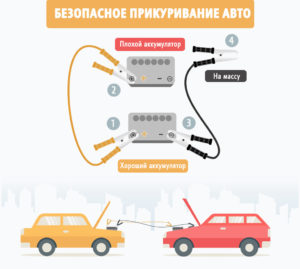 Самым простым способом зарядки АКБ является запуск автомобиля методом «прикуривания» от другого авто, после чего нужно двигаться на автомобиле около 20-30 минут. Для эффективности зарядки от генератора предполагается либо динамичная езда на повышенных передачах, либо движение на «низах».
Главным условием является поддержание оборотов коленвала на отметке около 2900-3200 об/мин. На указанных оборотах генератор обеспечит необходимый ток, который позволит подзарядить батарею. Отметим, что данный способ подходит только при условии частичного, а не глубокого разряда АКБ. Также после поездки все равно потребуется реализовать полный заряд аккумулятора.

Как заряжать аккумулятор — этот вопрос рано или поздно встает перед любым автомобилистом, и наиболее часто это происходит в зимний период с приходом холодов и возросшей нагрузкой на аккумулятор.
Аккумулятор – это химический источник тока, состоящий из нескольких источников, собранных в батарею. Один элемент (еще одно название — банка) имеет напряжение 2,1 В. Они объединяются последовательно в количестве 6 штук. За счет объединения нескольких элементов в одну батарею получается напряжение 12.6 В. При запуске автомобиля стартером на него подается напряжение 12,6 вольта, но большого тока. Это дает возможность провернуть стартером коленвал двигателя.
Какие бывают аккумуляторы

Аккумуляторные батареи за более чем 150 лет со времени изготовления первой постоянно совершенствовались, но конструкция и принцип работы остались неизменными. Сегодня можно встретить различные виды, у которых различный состав электролита и материалы электродов.
Виды аккумуляторов:

1. Свинцовые:
- свинцовые. Самые первыми стали выпускаться аккумуляторные батареи свинцовые с серной кислотой в качестве электролита. Они обладают возможностью выдать большой ток для запуска автомобиля. Такие аккумуляторы используются до сих пор. Но в связи с тем, что свинец очень мягкий материал, то сейчас производят легирование его различными материалами.
- Сурмянистые — свинцовые с добавлением сурьмы. Для улучшения качеств свинца в него стали добавлять сурьму. Сурьмянистыми называются аккумуляторы, которые имеют в составе электродов больше 5% сурьмы. Этот материал активизирует процесс электролиза, во время которого происходит разложение воды в электролите на кислород и водород, что выглядит как закипание электролита. Большое испарение воды приводит к оголению пластин электродов и их разрушению. Поэтому в такие АКБ приходится подливать воду. Из-за этого их еще называют обслуживаемыми. Такие аккумуляторы в современных автомобилях не используются. Они применяются в стационарных источниках питания, где требуется неприхотливость батарей.
- Малосурьмянистые свинцовые батареи – те в которых используется меньше 5% сурьмы. В такие аккумуляторы уже не требуется слишком часто заливать воду. Но потери электролита все равно присутствуют, и воду в них заливать все равно требуется.
- Кальциевые свинцовые аккумуляторы получают добавлением в свинец кальция вместо сурьмы. Использование этого вещества снижает интенсивность электролиза, и испарение воды в них практически отсутствует. Добавление серебра в такие батареи также улучшает КПД и увеличивает емкость батареи. Главным минусом кальциевых батарей является потеря их свойств при сильном разряжении. Несколько случаев глубокого разряда приводит к тому, что емкость аккумулятора сильно и необратимо падает.
- Гибридные свинцовые. Гибридные аккумуляторные батареи – это те, в которых используются сразу две технологии: сурьма для положительного электрода и кальций для отрицательного. Такие батареи имеют средние характеристики: надо чаще подливать воду, но они более устойчивы к глубокому разряду.
- Свинцовые AGM и гелиевые – представляют собой свинцовые аккумуляторы, у которых электролит связан и не может вытечь при опрокидывании. В AGM используется пористое стекловолокно, которое пропитывается электролитом. Гелевые АКБ получаются добавлением соединений кремния. Такие аккумуляторы устойчивы к вибрации и имеют низкий саморазряд. Выдают пусковой ток вне зависимости от заряда батареи практически до полного разряда. После разряда полностью восстанавливают свою емкость и выдерживают большое количество разрядов-зарядов (около 200).

2. Щелочные:
Щелочные АКБ имеют в качестве электролита щелочь. В стартерных аккумуляторных батареях применяются крайне редко.
Щелочные батареи бывают:
- никель-кадмиевые. Они имеют положительный электрод с покрытием гидроксидом, метагидроксидом или гидратом окиси никеля. Минусовой электрод покрыт железом с кадмием. В качестве электролита используется едкий калий.
- Литий-ионные. Это весьма перспективные аккумуляторные батареи, используемые в качестве дополнительных источников тока. У них в качестве минусового электрода — литий или литий-ферро-фосфатные сплавы. Плюсовой электрод — оксид лития с марганцем и кобальтом. Такие аккумуляторы имеют большую удельную емкость и низкую степень саморазряда. Из недостатков – чувствительны к отрицательным температурам, имеют низкое число зарядов-разрядов.
Зарядные устройства для аккумулятора

Основное назначение зарядного устройства — зарядить аккумулятор. Зарядных устройств на рынке автотоваров много, нужно выбрать наиболее подходящее по функциям и стоимости.
По конструкции зарядные устройства подразделяются на группы:
- пуско-зарядные устройства, которые помогут моментально завести машину, когда нет времени заряжать аккумулятор. Они отдают кратковременный импульс большой мощности, который помогает прокрутить двигатель.
- Трансформаторные – устаревшие модели, сейчас не выпускаются, но стабильные и долговечные.
- Импульсные – в них ток подается по мере зарядки; они предназначены для постепенной зарядки аккумулятора.

Зарядные устройства для аккумуляторов бывают:
- автоматические. Автоматические зарядники не могут заряжать сильно убитые аккумуляторы, поскольку не воспринимают нагрузку на своих клеммах, и не начинают их заряжать. Они хороши для полного цикла зарядки, поскольку автоматически регулируют подачу тока и плавно снижают зарядный ток по мере набора заряда аккумулятором и сами отключаются при полном заряде. Такие зарядники можно оставить работать на всю ночь без присмотра.

- Зарядники с ручной регулировкой тока. В продаже есть много недорогих моделей зарядников с ручной регулировкой, которые смогут зарядить даже сильно и длительно разряженные аккумуляторы, подавая вначале ток крайне слабой силы. Он подает ток постоянной силы, и за таким зарядником нужно постоянно следить, так как возможен взрыв из-за резкого «закипания» электролита.

По выходному напряжению бывают:
- 6 В — обычно применяются для зарядки АКБ скутеров и мотоциклов;
- 12 В — используются для зарядки АКБ легковых автомобилей;
- 24 В — заряжают АКБ сельхозтехники.

Также зарядные устройства различаются по:
- мощности, она должна быть больше чем емкость аккумулятора;
- току зарядки. Еще один параметр, который обязательно должен контролироваться и регулироваться зарядным устройством. Для зарядки ток не должен превышать 10% от емкости аккумулятора. Для АКБ емкостью 55 А-ч его величина должна быть 5,5 А. Максимальный ток, который может выдавать зарядное устройство – должно быть в 2-3 раза выше номинального требуемого для зарядки.
Для зарядки гелевых аккумуляторов требуется наличие у ЗУ специального режима. Кроме этих параметров зарядные устройства снабжают схемами защиты от перегрева, неправильного подсоединение клемм к выводам, интеллектуальными системами управления зарядкой.
Зарядка аккумуляторов

Чтобы правильно зарядить аккумулятор, делать это нужно в помещении, где есть вытяжка и желательно при комнатной температуре, так как при минусовой температуре процесс зарядки идет хуже. Было бы неплохо проводить полную зарядку два раза в год – осенью и весной. После долгого простоя в холодное время года — это обязательно, если вы заботитесь о долговечности работы своего аккумулятора.
Удобнее заряжать аккумулятор зарядным устройством, позволяющим регулировать напряжение и ток зарядки. Иначе на 100% зарядить батарею очень трудно. Если ваш зарядник не имеет специальных режимов, то придется самостоятельно регулировать ток зарядки и контролировать появления газов в конце процесса.
Для обеспечения полного заряда при достижении напряжения в 14,4 В ток снижается на половину и продолжается зарядка до тех пор, пока не начнется выделение газов. В современных аккумуляторах при достижении напряжения зарядки до 15 В полезно уменьшить зарядный ток еще в два раза.
Полностью заряженным считается аккумулятор, у которого ток зарядки и напряжение не будут меняться в течении 1-2 часов. У необслуживаемых АКБ состояние полной зарядки наступает при напряжении 16,3- 16,4 В.
У автоматических зарядников не требуется часто контролировать ток и напряжение заряда. Когда процесс зарядки батареи подходит к концу, будет увеличиваться внутреннее сопротивление батареи и соответственно будет снижаться ток заряда. При падении тока зарядки до 200 мА процесс останавливается полностью.
Как определить заряжен или разряжен аккумулятор

Это можно сделать двумя способами:
- Измерить плотность электролита с помощью ареометра. Зная температуру окружающей среды и плотность электролита можно определить степень разряда АКБ по таблице.
Узнать подробнее о том что такое плотность электролита, какой она должна быть, как ее измерить, как правильно ее корректировать вы можете в нашей статье Плотность электролита в аккумуляторе
- Измерить напряжение на клеммах аккумулятора — для измерения напряжения на клеммах аккумулятора используют нагрузочную вилку или цифровой мультиметр. Напряжение на клеммах аккумулятора 12,6 В и выше означает полностью заряженную аккумуляторную батарею, напряжение 11,6 В и ниже означает, что аккумуляторная батарея полностью разряжена.
Узнать подробнее о том что такое нагрузочная вилка, как ее использовать для проверки состояния аккумулятора, ознакомиться со списком 10 лучших нагрузочных вилок вы можете в нашей статье Нагрузочная вилка для аккумулятора
Правила безопасности при зарядке аккумулятора

При зарядке аккумулятора нужно соблюдать требования техники безопасности:
- не рекомендуется заряжать в непроветриваемом помещении по причине выделения смеси водорода и кислорода, образующихся при электролизе;
- рядом с заряжающимся аккумулятором нельзя курить и выполнять работы с открытым огнем и искрообразованием;
- сначала подключают клеммы, а потом включают в сеть;
- отключение в обратном порядке – сначала отключают от сети, потом отключают клеммы;
- в обслуживаемых аккумуляторах выкручивают пробки.
Как зарядить аккумулятор

Пошаговая инструкция как зарядить аккумулятор:
- отсоединить и снять аккумулятор;
- занести его в помещение, имеющее вытяжку и плюсовую температуру, дать отстояться;
- очистить клеммы от окисной пленки;
- очистить от грязи корпус АКБ;
- осмотреть на предмет отсутствия повреждений корпуса и утечки электролита;
- подсоединить зарядное устройство учитывая полярность;
- настроить зарядное устройство: установить ток и напряжение зарядки в зависимости от емкости и типа АКБ.

У обслуживаемых аккумуляторов перед подсоединением зарядника следует выполнить следующие действия:
- Выкрутить пробки банок и проверить уровень электролита
- Долить дистиллированную воду в банки так, чтобы электролит полностью закрывал пластины
- Проверить плотность электролита (при 25оC его плотность должна быть в пределах 1,16 – 1,25 г/см3)
Узнать подробнее о плотности электролита в аккумуляторе, выборе плотности электролита в зависимости от региона эксплуатации автомобиля, о том как проверить и откорректировать плотность электролита вы можете в нашей статье Плотность электролита в аккумуляторе
- Закрыть отверстия пробками, но не закручивать, чтобы грязь не попала внутрь.
Как заряжать постоянным током
Для зарядки постоянным током используется зарядные устройства с возможностью постоянной поддержки тока зарядки. Используются две ступени зарядки.
Первая ступень – ток зарядки равен 10% от емкости батареи (если емкость 60 А-ч – ток зарядки – 6А). Вторая ступень – ток зарядки 5% от емкости батареи. Она используется для устранения негативных факторов, которые возникают при зарядке близкой к 100%.
Время зарядки составляет 10 – 12 часов. Если есть возможность использовать ареометр для контроля плотности, то замеряя плотность, можно определить степень зарядки по плотности электролита.
Как заряжать постоянным напряжением
Для зарядки постоянным напряжением используется источник с выходным напряжением 14,4-15 В при зарядки аккумулятора выдающего 12,6 В. Для батареи, выдающей 6,3 В, используется блок питания с выходным напряжением 7,2–7,5 В.
Основным недостатком такого способа является большой ток зарядки в начале процесса, что может привести к перегреву электролита. В случае зарядки при низкой температуре окружающей среды в АКБ возникает большое внутреннее сопротивление, и заряд таким способом затруднен.
При возможности регулировки тока зарядки его выставляют в размере 95% от емкости. Процесс при таком способе получается быстрым без перегрева и сильного выделения газов. Другим недостатком такого способа является не полный заряд аккумулятора, что снижает срок его службы.
Сколько времени необходимо заряжать аккумулятор
Строго определенного времени сколько надо заряжать аккумулятор нет.
Время на зарядку разное и зависит от:
- емкости батареи и степени ее разряда;
- температуры окружающей среды;
- возраста и степени сульфатации пластин.
Кроме тока, который регулируют при зарядке важно выставить напряжение:
- При выходном напряжении ЗУ — 14,4 В — в течении суток батарея зарядится на 80%.
- При выходном напряжении ЗУ — 15,0 В — в течении суток батарея зарядится на 90%.
- При выходном напряжении ЗУ — 16,0 В — в течении суток батарея зарядится на 100%. Важен и ток зарядки. В современных устройствах он регулируется автоматически.
Время на зарядку аккумулятора высчитывают по простой формуле:
t= C/I +10%, где:
- t — время зарядки;
- С – емкость аккумулятора;
- I — мощность ЗУ;
- 10% — потери энергии на тепло.
Как заряжать необслуживаемые АКБ

Большинство современных аккумуляторов — необслуживаемые. В них нет пробок для добавления электролита, крышка плотно зафиксирована. Сверху или сбоку имеется индикатор заряда, по которому можно узнать о состоянии АКБ. Для зарядки необслуживаемых аккумуляторов рекомендуется использовать автоматические зарядные устройства, которые которые лучше остальных справляются с этой задачей.
Выбрав нужный режим и поставив аккумулятор на зарядку, можно не волноваться о необходимости контроля и регулировки режимов. Устройство сделает все само. Если у вашей зарядки нет таких режимов, то следует заряжать в щадящем режиме при токе зарядки – 3-5 А. Будет заряжаться дольше, но срок службы аккумулятора тоже увеличится.
Как часто надо подзаряжать аккумулятор

Часто подзаряжать не следует. Рекомендуется зарядить аккумулятор перед морозами и второй раз – весной. Низкий заряд АКБ в зимнее время упадет еще ниже при низкой температуре. При высоких летних температурах низкий заряд батареи приведет к усилению сульфатации пластин и росту кристаллов сернокислого свинца, которые не смогут раствориться даже когда АКБ заряжен полностью.
Хорошо проверять напряжения АКБ с помощью цифрового мультиметра. Если напряжения на клеммах аккумулятора не меньше 12,6 В, то можно не волноваться. При напряжении ниже 12,6 В требуется подзарядка.
Можно ли заряжать аккумулятор, не снимая его с автомобиля

Не рекомендуется проводить зарядку, не снимая его с автомобиля. В процессе зарядки используются высокие токи и повышенные напряжения. Современный автомобиль буквально напичкан электроникой, и просто заглушив мотор, нет гарантии, что все электронные устройства автомобиля будут отключены от АКБ. Заряжая его повышенным напряжением и током можно вывести из строя электронику.
Как заряжать АКБ при редких поездках

Если вы ездите на машине достаточно редко, и поездки короткие, то аккумулятор не успевает за время поездки подзарядиться от генератора. В таких случаях аккумулятор быстро разряжается, поскольку он испытывает нагрузку, когда вы заводите автомобиль и не подпитывается в поездке, что особенно заметно в зимний период.
В таком случае автовладельцы подключают зарядные устройства и подпитывают АКБ постоянно. Такое режим не является правильным и сокращает срок службы батарей. Лучше заряжать автомобиль привычным способом – от генератора после пуска мотора или от зарядного устройства.
Если вы совсем не ездите на машине зимой, то перед установкой автомобиля на хранение, батарею следует полностью зарядить и не одевать минусовую клемму.
Выводы
- Для сохранения и увеличения срока службы аккумулятора нужно следить за зарядом АКБ, своевременно его обслуживать, соблюдать инструкцию при зарядке и купить правильные зарядного устройства.
- Задачей зарядного устройства является подзарядить батарею достаточно для запуска автомобиля, чтобы генератор смог зарядить ее полностью.
- В случае глубокого разряда заряд обязательно производить на минимальных токах и постоянном напряжении, чтобы можно было восстановить емкость батареи до нормальной.
- При сильных морозах желательно иметь плотность электролита выше 1,3 г/см3 – это не даст электролиту замерзнуть.
- В жару плотность электролита лучше иметь меньше 1,25 г/см3 — это снизит скорость коррозии пластин.
- Нормальная температура для заряда аккумулятора от 0 до 25оC. Поэтому место нахождения аккумулятора (под капотом, в салоне, в багажнике или снаружи) влияет на вероятность восстановления температуры электролита и состояние батареи.
Product description
Genuine Arlec Battery Charger PRO 12 Volt 2.5 Amp Auto Car Bike with Led and Circuit Protection Genuine Arlec branded, the name you know you can trust. Charges 12 volt batteries, continuous charging. Perfect for Charging the battery overnight 12-15 hours. For ease of operation all the indicators are mounted on the front panel of the charger. The output leads are fitted with coloured battery clips for easy identification of polarity. The charger is protected internally by a thermal overload switch. Compact unit stores easily, always on hand when you need it. Comes complete includes battery leads and clips. Easily accessible 2 metre leads fitted with battery clips. Ideal for cars, caravans, campervans, 4-wheel drives, boats, motorcycles and ride-on mowers. Specifications: Brand: Genuine Arlec Charges: 12 Volt Overload Switch: Yes
OWNER’S MANUAL
FLEET POWER
INVERTER/BATTERY CHARGERS
FLEET POWER 1000
FLEET POWER 2000
FLEET POWER 2500
C
U
®
L
KKK
Fleet Power 1000 & 2000 models are certified by UL to comply with FED spec-KKK-A1822, SAE spec-SAE-JRR1, for emergency vehicle application. All models UL and C-UL Listed for Canadian use.
90-0115-00
10/97 Fltman.pm65
INTRODUCTION
General safety information for installation and operation is contained throughout this manual where it applies and are not included in this summary.
Warnings Warning statements identify conditions or practices which could result in personal injury, loss of life, damage to equipment or other property.
Fuse Replacement For continued protection against the possibility of fire, replace the fuse only with a fuse of the specified voltage, current and type rating.
Power Source To avoid damage, operate the equipment only within the specified AC (line) and DC (battery) voltages.
Servicing To reduce the risk of electric shock do not open this unit. There are no user serviceable parts inside. Refer all servicing to qualified personnel.
The statements, specifications and instructions in this publication are believed to be correct. No warranty is made, expressed or implied by the seller or manufacturer with respect to any results or lack thereof from the use of information in this publication and no liability is assumed for any direct or consequential damages, personal loss or injury. All statements made herein are strictly to be used or relied on at the user’s risk.
© 1997 Heart Interface Corporation. All rights reserved.
2
90-0115-00
10/97 Fltman.pm65
TABLE OF CONTENTS
Introduction . . . . . . . . . . . . . . . . . . . . . . . . . . 4
Things You Should Know . . . . . . . . . . . . . . . 5
Circuit Breaker Protection
Electronic Protection
Power Sharing
Power Switch
Remote Control Programming
Operation . . . . . . . . . . . . . . . . . . . . . . . . . . . . 6
Remote Control Panel . . . . . . . . . . . . . . . . . . 7
Remote Power Switch
System Status LEDs
DC Volts Bargraph
DC Amps Bargraph
Dip Switches
Equalize or 3-Stage Charging
Battery Type
Auto Range
Power Sharing
Dip Switch Status
Remote Control Wiring
Link 2000 Remote Control
Status LEDs . . . . . . . . . . . . . . . . . . . . . . . . . 10
Dip Switch Programming . . . . . . . . . . 11
Batteries . . . . . . . . . . . . . . . . . . . . 12
Battery Types
Battery Interconnection
Battery Bank Ratings and Sizing
Battery Charging . . . . . . . . . . . . . . . . . . 16
Conventional Battery Chargers
Fleet Power Battery Charger
Charging Over-Discharged Batteries
Battery Charger Voltage Table . . . . . . . . . . 21
Installation Precautions . . . . . . . . . . . . . . . 22
Installation . . . . . . . . . . . . . . . . . . . . . . . 23
Key Installation Points
Location
Grounding
Neutral Bonding
AC Wiring
Ground Fault Circuit Interrupters
Remote Control Wiring
DC Wiring
Battery Cable Fusing
Installation Options . . . . . . . . . . . . . . . . . . 29
DC Wiring Options . . . . . . . . . . . . . . . . . . . 32
Troubleshooting . . . . . . . . . . . . . . . . . . . . . .34
Glossary . . . . . . . . . . . . . . . . . . . . . . . . . 36
Specifications . . . . . . . . . . . . . . . . . . . 38
Warranty . . . . . . . . . . . . . . . . . . . . . . 40
3
90-0115-00
10/97 Fltman.pm65
INTRODUCTION
This owner’s manual describes the
Fleet Power Inverter/Chargers from Heart
Interface. These units perform three distinct functions:
1. DC to AC power inverting.
2. Automatic transfer switching between
inverter power and incoming AC power.
3. Automatic 3-Stage Battery charging plus
manual battery equalizing.
4. AC to DC power converter.
• The inverters provide regulated 120 Volt
AC power and crystal controlled frequency at 60Hz from a deep cycle battery bank in specified watts:
FP 1000-12…………….1000 watts
FP 2000-12…………….2000 watts
FP 2500-12…………….2500 watts
The output is a modified sinewave and is compatible with appliances, tools and other 120 VAC equipment. Momentary surge power of three times the inverter rating is available for starting electric motors. High efficiency insures the longest possible battery life between recharges.
• The transfer switch allows the Fleet Power
Inverter/Chargers to be connected to an external AC source and transfer the source through to the loads. When disconnected, the transfer switch allows automatic switching back to the inverter.
Fleet Power Inverter/Chargers operate as self-contained backup power systems, just add batteries.
• Fleet Power battery chargers are electronically controlled and rated:
FP 1000-12………………50 Amps DC
FP 2000-12…………….100 Amps DC
FP 2500-12…………….130 Amps DC
They are designed to rapidly and optimally recharge either wet* or gel* cell deep-cycle batteries. Battery charging is accomplished in 3 automatic stages: Bulk Charge, Acceptance Charge and Float Charge. In addition, using the remote control, a manually-engaged Equalizing Charge cycle is possible.
With an external AC source connected, the Fleet Power charger also serves the functions of a AC to DC converter to supply all of the DC loads which are connected to the battery.
Simple, automatic operation is made possible by the microprocessor in the Fleet
Power Inverter/Chargers. In most cases, the unit is left on and no attention or maintenance is required.
*Adustable with optional remote
4
90-0115-00
10/97 Fltman.pm65
THINGS YOU SHOULD KNOW
The optional Fleet Power Remote
Control Panel provides a power switch, system status LEDs, DC Volts and DC Amps
LED bargraphs. On the back of the remote is a set of dip switches which allow adjustment of the following:
• Manual Initiation of Equalize Charging
• Ambient Battery Temperature
• Battery Type
• Charger Mode (Auto or Controlled)
• Power Sharing
Circuit Breaker Protection
Fleet Power Inverter/Chargers are circuit breaker protected.
The Fleet Power 1000 has a 12 Amp
INV/CHG circuit breaker on the front of the unit that protects against sustained inverter overloads over 1440 watts and the AC input to the battery charger. The 15 Amp INPUT circuit breaker on the unit protects the incoming AC circuit which is transferred through to the loads via the GFCI.
The Fleet Power 2000 has a 25 Amp
INV/CHG circuit breaker that protects against sustained inverter overloads over
3000 watts and the AC input to the battery charger. .
The Fleet Power 2500 has a 30 Amp
OUTPUT circuit breaker on the unit that protects against sustained inverter overloads over 3600 watts. The 30 Amp circuit breaker protects the incoming AC leg which feeds the battery charger.
The 30 Amp TRANSFER circuit breaker on the units protect the incoming AC circuit which is transferred through to the loads connected by the hardwire output.
The 15 Amp circuit breaker protects the
GFCI outlet on the Fleet Power 1000 and
2000 models. When a circuit breaker trips, the circuit breaker is reset by pushing the button back in.
Electronic Protection
Fast acting electronic circuits protect the inverter from extreme overloads and short circuits. Other protection includes a low and high battery cutoff and automatic shutdown if over temperature occurs. The fault condition must be eliminated before reset will occur. Example: remove overload, recharge batteries or allow to cool.
Reset by cycling the power switch OFF/ON.
Power Sharing
When connected to shorepower or using a generator, the battery charger and transfer functions are engaged. A unique power sharing feature automatically reduces the AC consumption of the battery charger allowing necessary AC power to the load.
This prevents the circuit breaker from tripping. This feature can be adjusted using the remote control panel. This feature is set at the transfer rating of each unit by default.
INPUT
INV/CHG
GFCI
Fleet Power 2000 shown.
5
90-0115-00
10/97 Fltman.pm65
OPERATION
Power Switch
The Power Switch is located on the front panel. This switch controls ON/OFF and RESET for the inverter. Expect a 3 second delay when the power switch is turned ON before the unit is activated.
If the unit is connected to external AC power, the battery charger and transfer switch will continue to function, regardless of the position of the switch.
When external AC power is removed and the power switch is in the ON position, the inverter will automatically be ON. If the switch is in the OFF position and external
AC power is removed, the inverter will be
OFF.
Inverter overload protection, transfer switching, power sharing and battery charger regulation will all function automatically.
If installed with the remote control panel, the power switch on the unit should be left in the OFF position. Refer to Remote Control Panel, page 7.
Power Switch
Fleet Power 1000 shown.
6
90-0115-00
10/97 Fltman.pm65
REMOTE CONTROL PANEL
An optional remote control panel is available which offers several features not found on the unit. The remote control panel provides LED bargraphs which show system status, battery voltage, and DC Amps in both inverter and charge modes. These bargraphs can also display dip switch positions and shut down conditions.
Volts bargraph will stop indicating battery voltage and display the dip switch settings.
It will return to indicating battery voltage only after the unit has been reset.
DC Amps Bargraph
These LEDs approximate DC input current in inverter mode and DC output current in battery charger mode. Two ranges are used — below 50 Amps each segment represents a 10 Amp increment, above 50 Amps each segment represents a
20 Amp increment. Above 130 Amps, a flashing LED segment indicates the value displayed plus 100 Amps (flashing 50 LED is equal to 50 + 100 or 150 Amps DC).
If a shutdown occurs, the DC Amps bargraph will stop indicating DC Amps and will indicate the type of problem . Each LED segment indicates a different problem as described in the troubleshooting section on page 34.
Remote Power Switch
The switch on the remote is used to control the inverter and can also be used to control the battery charger function. When a remote control is used, the power switch on the inverter should be left in the OFF position.
System Status LEDs
These 4 LEDs monitor the system as described in the table on page 10.
DC Volts Bargraph
These LEDs indicate battery voltage as measured inside the unit. Each LED segment indicates .5 Volts. If an overload occurs and the unit shuts down, the DC
7
90-0115-00
10/97 Fltman.pm65
REMOTE CONTROL PANEL
Dip Switches
On the back of the Fleet Power remote control panel is a set of 8 dip switches which are used to make several adjustments. On the switch block, each switch is numbered . . .1 through 8 and the ON position is indicated. The switch settings can be changed at any time, even while the unit is operating. Following is a discussion of each adjustment. Refer to the table on page 11 for dip switch programming.
BACK VIEW
Fleet Power Remote Control Panel
SWITCH 1 —
Manual Equalizing Cycling this switch ON for 1 second, then OFF, will initiate an equalizing charge cycle. The battery charger must be engaged before cycling the switch. The dip switch must
always be returned to the OFF position.
If it is left ON, an equalizing charge cycle will initiate every time the charger is engaged — this could cause battery damage.
The equalizing cycle is timed to last 8 hours from the time the switch is cycled, at which point the charger resumes normal charging in the float stage.
The battery LED blinks when equalizing. See page 18 for a discussion of the theory and procedure for battery equalizing.
SWITCH #2 & #3 —
Battery Type Gel cell and wet cell batteries have slightly different charge voltage requirements. Optimum battery charging is temperature dependent.
For these reasons, the dip switches allow four different battery charger voltage set points, depending on battery type and ambient temperature:
Cool Wet Cell
Warm Wet Cell
Cool Gel Cell
Warm Gel Cell
< 80 degrees F.
> 80 degrees F.
< 80 degrees F.
> 80 degrees F.
Refer to the table on page 21 for the specific voltages for each setting.
SWITCH #4 —
Auto Charge With the switch in the OFF position, the remote panel ON/
OFF switch only controls the inverter operation. With the switch turned ON, it allows the power ON/OFF switch on the front of the remote to control the battery charger as well as the inverter.
SWITCH #5 & #6 — Not used for adjustments.
SWITCH #7 & #8 —
Power Sharing These switches should be set to match the value of the circuit breaker which protects the incoming AC power. They may also limit the output current from the battery charger.
8
90-0115-00
10/97 Fltman.pm65
REMOTE CONTROL PANEL
Use the 5 Amp setting for small generators, or for charging deeply discharged batteries.
Dip Switch Status
You can check the position of the dip switches by quickly cycling the power switch
OFF/ON twice. The DC Volts bargraph will cease to display battery voltage and will indicate the settings of each dip switch. In this mode the bottom LED will illuminate if switch 1 is on; the second LED will illuminate if switch 2 is on, etc. Dip switch settings are indicated for 10 seconds after which time the display returns to indicating battery voltage.
Factory default settings for all dip switches are in the Off position.
Remote Control Wiring
The remote control panel is supplied with 25 or 50 ft. of telephone cable. The cable supplied may be 6 conductor, however, only 4 conductor is required. You may buy standard 4 conductor telephone cable and run up to 50 ft., if desired. Use only a single length of telephone wire, do not splice.
Refer to page 11 for the Dip Switch
Programming chart.
9
90-0115-00
10/97 Fltman.pm65
STATUS LEDs
Status LED Purpose
INV/CHRG
(Inverter/Charg
Power on light. It will be illuminated whenever the power switch is on (inverter on) or when there is incoming AC power and the charger comes on.
AC Input
Steady
Overload
Blinking
Overload
Illuminates when incoming AC power has been applied and the transfer relays have engaged.
There is a 7-12 second delay from the time the AC is applied and this LED illuminates.
Indicates an over-temperature condition, the unit is shut down. It will reset automatically after cooling.
Inverter mode- Shutdown, diagnose problem using
DC Amps bar graph. Charger mode- Thermal shutdown, after cooling reset by cycling power switch.
Steady Battery
This is a High/Low Battery warning condition.
Inverter mode: Battery > 15.25 or < 10.50 volts
Charger mode: Battery > 15.25 or < 10.00 volts
Blinking
Battery
Indicates either a shutdown or equalizing.
Battery > 15.50 volts, will auto-reset at 15.25.
Inverter mode: Battery < 10.00 volts, will auto reset at charger float voltage or upon AC input.
Charger mode: Battery < 8.00 volts for 1 minute, remove all DC loads and manually reset by cycling
10
90-0115-00
10/97 Fltman.pm65
DIP SWITCH PROGRAMMING
Feature
Equalize or
3 Stage
Charging
Battery
Type
Off
On
Off
4
Off
2
On
1
Switch
Number
Toggle
On/Off
Set Point
Equalize (Do not leave on.)
3 Stage Charging*
3
On Warm Gel Cell (>80 deg. F.)
On Cool Gel Cell (<80 deg. F.)
Off Warm Wet Cell (>80 deg. F.)
Off Cool Wet Cell (<80 deg. F.)*
Auto
Charge
Power
Sharing
On
Off
5
7
On
Off
On
Off
Disable: Charger responds to On/Off switch.
Enable: Charger on when AC connected.*
Not used.
6
8
1000
On 2.5 Amps
2000
5 Amps
2500
5 Amps
On 5 Amps
Off 10 Amps
15 Amps
20 Amps
20 Amps
30 Amps
Off 15 Amps* 30 Amps* Disabled*
*indicates factory default setting.
11
90-0115-00
10/97 Fltman.pm65
BATTERIES
BATTERY TYPES
Use only deep-cycle batteries with your
Fleet Power Inverter/Charger. These fall into two broad categories, wet cell and gel cell.
Wet Cell Batteries
True deep-cycle wet cell batteries are characterized by relatively thick plates that are alloyed with antimony.
Common marine/RV deep-cycle
batteries are acceptable. However, golf
cart batteries have better performance and life. They are 6 Volt batteries that must be used in series pairs. High quality marine
deep-cycle batteries offer good perfor-
mance and are available in a wide variety of sizes. Floor sweeper, fork lift or large 2
Volt cells can also offer excellent performance, if their large size can be accommodated.
It should be noted that high antimony deep-cycle batteries will give off gas as a natural result of charging and will experience some water loss. It is very important
that the electrolyte level be checked
frequently and topped off with distilled water when necessary. Never allow the tops of the plates to be exposed to air, as contamination of the cell will result. Keeping the tops of batteries clean will reduce self-discharging. Always provide ventilation for the battery storage compartment.
Do not use car batteries or engine starting batteries of any kind with your inverter/charger. Beware of any battery that is rated in Cold Cranking Amps (CCA). This is a rating which applies only to engine starting batteries. In general, most wet cell batteries that are described as hybrid batteries, suitable for either engine starting or deep-cycle applications, are a compromise and will give limited life if deeply discharged.
Beware of 8-D starting batteries that are commonly used for starting diesel engines. These batteries are not deep-cycle.
12
90-0115-00
10/97 Fltman.pm65
BATTERIES
Beware of so-called maintenance-
free batteries. These batteries have calcium alloyed with the lead and hold the liquid electrolyte in a sponge-like material.
They are sealed and water cannot be added. Do no confuse them with true gel cell batteries, they will not hold up to deep discharging.
Gel Cell Batteries
Gel cell batteries are lead-acid batteries similar in many ways to the common wet cell battery, but differences in the chemistry and construction provide some unique features.
No Maintenance — There is no need to add water and the tops of the batteries stay clean. Also, the batteries can be used in any position and may be used without a battery box.
Low Self-Discharging — Unlike wet cell batteries, the gel cell will hold its charge for months if left sitting with no load and no float charge. They can be stored without a constant float charge and without fear of freezing.
Low Internal Resistance — The result of low internal resistance is a higher battery voltage under load, which will result in better inverter performance on demanding high power loads. In addition, this allows the gel cell to accept a high rate of charge, a plus for rapid recharging.
The features of the gel cell batteries solve many common problems. Cycle life is high, even under constant deep discharging.
BATTERY INTERCONNECTION
In most cases you will be using a bank of two or more batteries with your inverter/ charger. You may connect batteries together in two configurations, series and parallel.
Series
Connecting 2 batteries in series will double the voltage of the battery bank. For instance, two 6 Volt batteries connected in series will produce 12 Volts. The Amp-hour capacity of the battery bank will be the same as each individual battery. Example, two 6 Volt 220 Amp-hour batteries in series will produce on 12 Volt 220 Amp-hour battery bank.
—
—
+
+
Series
13
90-0115-00
10/97 Fltman.pm65
BATTERIES
Parallel
Connecting 2 batteries in parallel will double the Amp-hour rating of the battery bank, while the voltage will be the same as each individual battery. Example, two 12
Volt 105 Amp-hour batteries in parallel will produce one 12 Volt 210 Amp-hour battery bank.
+
+
—
—
Parallel
Only similar batteries should be
connected together in one bank. Do not connect old and new batteries together or wet and gel cell batteries together. In the above drawing, the load is connected to the positive terminal of the first battery and the negative terminal of the last battery. This practice helps to balance the battery bank and is called cross connecting the battery bank.
Always use proper terminals for your interconnecting battery cables which are appropriate to handle the current.
Battery Bank Ratings and Sizing
Deep-cycle batteries are usually rated in Amp-hours. The Amp-hour rating is based on a 20 hour discharge cycle, therefore, a 100 Amp-hour battery can deliver 5
Amps for 20 hours. If the discharge rate is greater than 5 Amps, the available Amphours are decreased. If the load is increased to 100 Amps, only about 45 Amphours will be available at this rate of discharge.
Another common rating is reserve
capacity expressed in minutes. This is derived by placing a 25 Amp load on the battery and measuring the time until the battery voltage reaches 10.5 Volts.
Deep-cycle batteries can be discharged about 80% before permanent damage occurs, though shallower cycling will result in much longer battery life. 50% cycling is generally considered to be a good compromise between long battery life and a reasonably sized battery bank.
14
90-0115-00
10/97 Fltman.pm65
BATTERIES
To achieve 50% cycling you should calculate your Amp-hour consumption between charging cycles and use a battery bank with twice that capacity.
To calculate Amp-hour consumption first look at the rating plate on your AC appliance or tools. Each appliance or tool will be rated in either AC Amps or AC watts or AC
VA (Volts-Amps) apparent power. Use one of the following formulas to calculate the DC
Amp-hour draw for a 12 Volt system:
(AC Amps x 10) x 1.1 x hours of operation = DC Amp-hours
(AC watts/12) x 1.1 x hours of operation
= DC Amp-hours
(AC VA/12) x 1.1 x hours of operation =
DC Amp-hours
In all formulas, 1.1 is the factor for inverter efficiency.
Calculate the above for every AC appliance or tool you intend to use on your inverter. This will give you the total number of Amp-hours used between recharges.
Size your battery bank using this number as a guideline. A good rule to follow is to size the battery bank about 2 times larger than your total Amp-hour load requirement. Plan on recharging when 50% discharged.
Typical PowerConsumption
Loads
On-Board Computers
Quartz Halogen Flood
0.2 HP Bench Grinder
Hammer Drill
3/8″ Electric Drill Motor
Sawzall
0.5 HP Bench Grinder
1.0 HP Tile Saw
0.5 HP Skil
®
Saw
2.0 HP Radial Arm Saw
2.5 HP Chain Saw
Hand Blower/Vacuum
Quartz Halogen Flood
11 gal. Air Compressor
Chain Saw
20 gal. Air Compressor
10″ Table Saw
10″ Miter Saw
Planer
Coring System
Watts
1200
1200
1200
1450
1500
1600
1700
1800
1800
1800
1800
2000
200
300
300
500
500
500
750
800
Many electric motors have momentary starting requirements well above their operational rating. Start up watts are listed where appropriate. Individual styles and brands of appliances may vary.
15
90-0115-00
10/97 Fltman.pm65
BATTERY CHARGING
Battery Charging
Completely recharging wet cell deepcycle batteries requires the battery voltage to be raised beyond what is known as the gassing point. This is the voltage at which the battery begins to bubble and gas is given off. If charging stops short of this point, sulfate is left on the plates and deterioration of the battery begins. The gassing point will vary with battery temperature.
Gel cell batteries must not be charged to their gassing point. In fact, high voltage charging which gasses these batteries is harmful to them. They typically require a lower bulk charge voltage and a higher float voltage. Consult the battery manufacturer for specifications.
Conventional Battery Chargers
Most conventional battery chargers are single-stage constant voltage chargers.
They must stop short of the gassing point or they will overcharge the battery bank.
Therefore, most 12 volt battery chargers bring the battery voltage up to about 13.8
Volts.
This presents two problems. First, since the battery voltage does not reach the gassing point, sulfate is left on the plates.
Second, 13.8 volts is close enough to the gassing point that some gas will escape, and the wet cell battery will need to be frequently topped off with distilled water.
Conventional battery chargers also suffer from another inherent characteristic of design, which is a tapering output. While they will deliver their rated current into a deeply discharged battery, as the battery becomes charged and the voltage rises, the output current of the charger tapers down.
This taper continues as the battery is charged, taking a very long time to reach an acceptable recharge.
Fleet Power Battery Chargers
Fleet Power battery chargers are designed to overcome the limitations of conventional chargers by utilizing 3 distinct stages, each designed for optimal recharging of both wet cell and gel cell deep-cycle batteries.
16
90-0115-00
10/97 Fltman.pm65
BATTERY CHARGING
NOTE: Fleet Power battery chargers are on whenever there is AC power connected to the charger input, regardless of the condition of the On/Off switch. This feature can be disabled by setting the dip switch #4
(back of the remote) to «On» so that the charger will also be controlled by the On/Off switch.
Each time the battery charger is engaged, the 3 stages proceed automatically, resulting in an efficient, complete recharge and safe battery maintenance. Use of the remote control provides the ability to periodically apply an 8-hour timed equalizing charge.
The battery charger stages are:
Stage 1 —
Bulk Charge During the bulk charge stage most of the charge current is delivered to the battery bank. This phase is engaged as soon as the battery charger is activated. Full rated charger current is delivered to the battery bank until the bulk charge voltage limit is reached. This results in a relatively rapid recharge.
Generally, a wet cell battery bank should not be charged up to the gassing point at a rate which exceeds 25% of its capacity. In other words, a 12 volt battery bank of 520 Amp-hours should not be charged at over 130 Amps.
17
90-0115-00
10/97 Fltman.pm65
BATTERY CHARGING
Gel cell batteries can accept a higher rate of charge. Consult the manufacturer for specifications.
Stage 2 —
Acceptance Charge The acceptance stage immediately follows the bulk charge stage. During this stage the battery voltage is held constant at the bulk charge voltage limit and the current gradually ramps down. During this stage the battery is accepting its final amount of charge current and the last of the sulfate on the plates is removed.
The acceptance stage lasts until the charge current reaches about 6-7 Amps. A timer will terminate the acceptance stage if this current level is not reached. This timer is set automatically when the dip switches for battery type are set. Maximum acceptance time is 1 hour for wet cells and 3 hours for gel cells. Gel cell acceptance time can be increased because the battery is not gassing. Expect wet cell batteries to gas somewhat during acceptance, this is a necessary part of the charging process.
Stage 3 —
Float Charge When the acceptance stage is terminated, either because the charge current ramped down to
6-7 Amps or the timer engaged, battery charger current will shut off. The unit monitors the battery voltage while it drifts down from the bulk charge voltage limit. When it reaches the float voltage set point, the float charge stage is engaged.
The float charge stage holds the battery voltage at a lower level, where it is safe for long term battery maintenance. During the float charge stage, the full output current of the battery charger is available to operate any DC appliances that may be on the system, while constantly maintaining the float charge voltage.
The battery charger remains in the float charge stage indefinitely until the charger is disconnected from incoming AC power.
Stage 4 —
Equalizing Charge This is the only battery charger stage which is not engaged automatically. It must be manually initiated each time it is necessary to equalize using a dip switch on the back of the remote control. Applying an equalizing charge is not possible without the use of a remote.
Periodic equalizing is recommended by most wet cell deep-cycle battery manufacturers. There are no firm rules for how often an equalizing charge should be applied, but once a month is a good rule of thumb for batteries which are regularly cycled, less often for systems in only occasional use.
The equalizing charge is a timed, 8hour cycle. If desired, it can be ended by interrupting the AC power to the charger at any time during the cycle. Equalizing should be engaged after the batteries have been fully charged by a normal battery
18
90-0115-00
10/97 Fltman.pm65
BATTERY CHARGING
charging cycle. The battery voltage will increase to 16.3 using the cool temperature wet cell setting. This will cause the battery bank to gas profusely and will accomplish the following:
1. Removal of residual sulfate. Each time a battery is cycled (discharged and recharged), a small amount of sulfate is left on the plates. Over time, this gradual build-up of sulfate will compromise the performance of the battery. By applying an equalizing charge, the sulfate is returned back to the electrolyte, raising the specific gravity and fully exposing the active material of the plates.
2. Bring all cells to the same potential.
All lead-acid batteries are made up of individual 2 Volt cells. As the battery bank is cycled, slight differences in the cells result in different cell voltages, affecting the overall charge effectiveness. Equalizing brings all cells up to the same voltage and the electrolyte in each cell to the same specific gravity.
3. Mixing up of the electrolyte. Electrolyte in battery cells tend to separate into layers of acid and water. The vigorous boiling action of the battery during equalizing serves to physically mix the electrolyte.
Equalizing is not required on gel cell batteries. You will note that if the dip switches are set in one of the two gel cell positions, the equalizing charge voltage is the same as the bulk charge voltage, therefore, equalizing is equivalent to an 8-hour acceptance stage and is not harmful.
To limit the DC current during equalizing to less than 15 Amps, turn on dip switches 7 and 8 before starting the equalize charge. Do not operate AC loads that are on the output of the inverter/charger when equalizing.
Charging Over-Discharged Batteries
Charging into a battery bank with a terminal voltage of less than 8 Volts presents a special problem for the unit. If this situation arises, the unit will attempt to charge for 1 minute. If the inverter senses excessive ripple voltage, it will shut down to protect itself.
To successfully charge an overdischarged battery, you must remove as
much DC load as possible. Set dip switches 7 and 8 to the ON position to limit the amount of charge current and the resulting ripple voltage. After the battery voltage has reached 10 Volts, these switches can be set to their previous positions.
19
90-0115-00
10/97 Fltman.pm65
BATTERY CHARGING
WARNINGS
1. Do not equalize gel cell batteries with the remote programmed for wet cells.
2. Always monitor the equalize
charge. Provide proper ventilation for battery fumes. Do not allow any sparks during equalizing. If one or more cells begin to overflow, terminate the equalize charge.
3. Check and top off the battery electrolyte both before and after the
equalizing charge. Do not expose the battery plates to air. Leave the battery caps on while equalizing.
4. Remove all loads from the DC sys-
tem before equalizing. Some DC loads may not tolerate the high charge voltage.
5. Do not leave the equalize dip
switch in the ON position. It must be cycled OFF and left in the OFF position.
If left ON, the unit will engage the equalizing cycle every time the battery charger is engaged.
Note: If a continuous DC load in excess of the charge rate is placed on the battery bank, eventually the battery voltage will drop below 8 Volts and the battery charger will shut off. This load must be significantly reduced and the power to the charger cycled to resume charging.
Blinking of the battery LED on the remote control while charging is a warning that an over-discharge is imminent and that the DC load should be reduced.
NOTE: Equalize only after a regular charge cycle.
20
90-0115-00
10/97 Fltman.pm65
BATTERY CHARGER VOLTAGE SETTINGS
B a t t e r y T y p e a n d
T e m p e r a t u r e
B u l k V o l t a g e /
M a x T i m e
W
1 2 a r
V m o l t W e t C e ll
T e m p e r a t u r e
C
1 2 o o l
V o l t W e t C e ll
T e m p e r a t u r e
W
1 2 a r
V m o l t G e l C e ll
T e m p e r a t u r e
C
1 2 o o l
V o l t G e l C e ll
T e m p e r a t u r e
1 4 .
0 / 1 h r
1 4 .
4 / 1 h r
1 3 .
8 / 3 h r
1 4 .
1 / 3 h r
F l o a t
V o l t a g e
1 3 .
1
1 3 .
5
1 3 .
3
1 3 .
6
E q u a l i z e
V o l t a g e
1 5 .
8
1 6 .
3
1 3 .
8
1 4 .
1
21
90-0115-00
10/97 Fltman.pm65
INSTALLATION PRECAUTIONS
CAUTION This equipment is not igni-
tion protected and employs components that tend to produce arcs or sparks. To reduce the risk of fire or explosions, do not install in compart-
ments containing batteries or flam-
mable materials or areas in which ignition-protected equipment is required.
WARNING
For continued protection against risk of electric shock, use only the ground-
fault circuit interrupter (GFCI) type
receptacles detailed in this owner’s manual. Other types may fail to operate properly when connected to this inverter, resulting in a potential shock hazard.
CAUTION
Risk of electrical shock. Both
AC & DC voltage sources are terminated
inside this equipment. Each circuit must be individually opened before servicing.
CAUTION Risk of electrical shock. Do not remove cover, no user serviceable
parts inside. Refer servicing to qualified service personnel.
APPLICATION INFORMATION Provided with
integral electronic protection against AC & DC overloads.
AC Inputs
AC Output
Remote
Jack
CAUTION To reduce the risk of electric shock and prevent premature failure due to corrosion, do not mount where exposed
to rain or spray.
CAUTION To prevent fire, do not obstruct ventilation openings. Do not mount in a zero clearance compartment, overheating may result.
NOTICE The output of this device is not
sinusoidal. It has a maximum total harmonic distortion of 47% and a maximum single harmonic of 34%.
Chassis
Ground
Lug
Fleet Power 2500 shown.
22
90-0115-00
10/97 Fltman.pm65
INSTALLATION
Key Installation Points
The Power Switch must be turned OFF before you begin.
1. Observe proper polarity when connecting batteries. Reverse DC polarity will result in damage to the unit and will void the warranty. Use care when making the
DC connections.
2. Do not back-feed the AC output of
the inverter with incoming AC power. A back-feed occurs when AC power from shore power or generator is connected to the output of the inverter. This will damage the inverter and void the warranty. Remember that incoming AC must be fed only to the AC input and never to the AC output.
Always check for AC voltage before connecting wires to the AC output. Do NOT turn the inverter ON until all AC connections have been made. Back-feeding the inverter voids the warranty.
3. Do not connect the AC input to the
AC output. In effect, this would be plugging the battery charger into the inverter.
This could occur if the unit is connected to the entire leg of a circuit breaker panel, then a circuit breaker on that leg is used to feed the battery charger. This will cause the unit to oscillate ON and OFF when the unit is in inverter mode.
4. Always use proper wire and con-
nectors. The proper battery cable size is critical because considerable amperage flows in the DC circuit. Fusing the positive
DC cable is required. The AC wire size is dependant on potential current in the circuit.
Consult the NEC (National Electric Code) for proper wire gauge.
5. Keep the inverter/charger out of the elements and out of direct contact
with water or spray. Remember that the unit is a piece of electronic equipment and treat it accordingly.
6. Mount the unit as close to the
batteries as possible but not in the presence of flammable fumes or in an enclosed battery compartment.
7. The connectors for the remote control and the chassis ground bonding lug, as well as for the AC wires, are lo-
cated on the bottom of the unit. Be sure to make these connections before bolting the unit down.
8. You may mount the unit horizon-
tally (on a shelf) or vertically (on a wall or bulkhead). If mounted vertically, you must orient the unit so the switch and the circuit breakers are facing up and the fan and battery cables are facing down.
9. Allow several inches of clearance
around the unit and allow for a supply of fresh air to the cooling fan. Do not block any of the vents or louvers. The fan pulls air from outside the unit. It blows air across the internal components, particularly the transformer and heat sinks, then out the side vents.
23
90-0115-00
10/97 Fltman.pm65
INSTALLATION
10. If installing in a system which includes an existing battery charger or converter, make sure these do not operate
from the inverter output AC power. This sets up a power loop which, due to inefficiencies, will quickly drain the batteries.
11. Make sure all wiring conforms to
local and national electrical codes. If in doubt, consult with a qualified electrician.
12. Keep the overall length of each
battery cable less than 10 feet. If needed, attach short extension cables. Do not use frame ground or a ground bonding system as a current carrying conductor. Run the negative cable directly to the battery bank.
If the positive and negative cables run parallel to each other, twist the cables together. This will minimize the adverse effects of inductance.
13. To meet electrical codes, a fuse must be installed in the positive battery cable within 18 inches of the battery post.
This fuse is intended to protect the battery and cables against a dead short circuit.
The inverter is protected internally and will not blow a properly sized fuse.
14. DC wiring is generally very simple, the positive and negative cables from the inverter/charger are connected to the house or auxiliary battery. In the case of multiple batteries the interconnecting jumper cables must be of the same AWG as those supplied with the inverter/charger.
15. If multiple battery banks are to be charged, a battery selector switch can be installed, allowing the banks to be charged either individually or simultaneously. A solenoid can also be used.
WARNING
Do not mount the unit in an enclosed battery compartment. Take precautions to keep road dirt and spray off the unit.
Grounding
For safety purposes, the chassis of
the inverter/charger must be connected
to your AC ground system. The chassis ground bonding lug is located on the bottom of the unit. This connector can accept two wires, the first is used to connect the unit to
AC ground, the second can be used to connect other AC equipment to ground.
Use bare copper insulated wire, solid or stranded. Strip one end and use a screwdriver to secure it to the chassis ground bonding lug. This wire will connect to the ground in your AC electrical system, typically the vehicle chassis. Make sure the connection is clean and tight.
24
90-0115-00
10/97 Fltman.pm65
INSTALLATION
This procedure will connect the chassis of your unit to AC ground. In addition, the
AC input and AC output green wires are connected to chassis ground. It is important to connect these wires to the AC ground bus in the circuit breaker panel.
Note: The battery cables are not connected to ground or the chassis of the unit.
Neutral Bonding
For safety purposes, the Fleet Power inverter/charger unit internally bonds the AC output neutral to the AC ground when the unit is OFF or in the inverter mode. When incoming AC power is applied and the transfer switch is engaged, the internal neutral-to- ground bond is automatically lifted.
This means that when the vehicle is connected to shore power, the grounding system is connected to the shore power ground, where neutral and earth ground are bonded together. This technique insures safety in all conditions and conforms to the requirements of the NEC.
AC Wiring
The AC wires route through the holes in the bottom of the unit. Use a screwdriver to remove the screws which secure the AC wiring compartment cover plate. Inside, the compartment is divided into 2 sections, one labeled AC Input, the other labeled AC
Output. Each side contains 3 pigtails: black, white and green. Six wire nut connectors are also provided.
Black
White
Green
Hot or Line
Neutral
Ground
Conventional metal strain reliefs are provided. These can be replaced by plastic strain reliefs for additional corrosion resistance or 3/4 inch conduit fittings if the wiring will be routed through the conduit.
Use proper wire sizes according to the
NEC.
AC Input (Fleet Power 1000 and Fleet
Power 2000): Feed the 3 conductor AC input wire through the strain relief and into the AC input compartment. You should have 6 inches of individually insulated black, white and green wire. Strip 1/2 inch of insulation off each conductor and connect to the pigtails: black to black, white to white and green to green.
AC Input (Fleet Power 2500): There are 2 options for configuring the AC input to the Fleet Power 2500.
Dual Inputs: The internal battery charger may be fed separately from the transfer input which feeds the AC loads. In this case, connect one 30 Amp feed to the charger pigtails and another 30 Amp feed to the transfer switch input.
Connecting the feeds in this way balances the AC loads when 2 legs of incoming
AC power are available. These two feeds can be in or out of phase. Transfer will only
25
90-0115-00
10/97 Fltman.pm65
INSTALLATION
WARNING
Do not connect incoming AC from any source to the AC output of the inverter/ charger. This is known as back-feeding and will damage the unit and void the warranty.
occur when power is applied to both inputs.
The charger can draw up to 27 Amps on one leg of power and the transfer switch can pass up to 30 Amps from the other leg of power.
Single Input: Both the battery charger and the transfer switch may be fed from the same AC input. In this case, connect both pigtails together, black to black, white to white and green to green.
This allows up to 60 Amps of AC power to be brought in on a single cable. Up to 30
Amps is available to the loads, with the balance available to power the battery charger. A single cable should be protected by a 60 Amp breaker or smaller, and 6 gauge wire should be used.
AC Output: On the Fleet Power 1000,
AC output is available at the GFCI outlet mounted on the unit. On the Fleet Power
2000, AC output is available at both the
GFCI outlet and at the AC output compartment. The AC output for the Fleet Power
2500 is available at the AC output compartment only. When installing the Fleet Power
2000 and 2500, feed the 3 conductor AC output wire through the strain relief and
26
90-0115-00
10/97 Fltman.pm65
connect in the same fashion as the AC input wires.
If you are not connecting the hardwire output wires (Fleet Power 2000 only), make certain they can not cause a short circuit to the wiring compartment. Tug firmly on each connection to make sure they are secure.
Check these connections first if the unit is not operating properly.
Carefully tuck the wires into the AC wiring compartment. Replace cover plate.
Ground Fault Circuit Interrupters
In order to conform to the NEC, certain branch circuits must be equipped with a
Ground Fault Circuit Interrupter (GFCI).
Please consult the code or a qualified electrician for details. Any such branch circuit must be protected by a circuit breaker consistent with the GFCI rating.
Underwriters Laboratories has tested the following GFCI, and its use is recommended. Receptacle Type:
Pass & Seymour
Catalog Number 1591-RW
Rated: 15 Amps at 120 Volts AC
Fleet Power 1000 and 2000 inverter/ chargers provide an integral GFCI outlet which is protected by a circuit breaker. This
GFCI outlet does not protect the hardwire
AC output. The hardwire AC output is protected by a non-GFCI circuit breaker on the Fleet Power 2000 only. The first outlet from the hardwire output should be GFCI protected to comply with applicable codes and standards.
The GFCI Receptacle is designed to protect from line-to-ground shock hazards which could occur from defective power
INSTALLATION
WARNING
Persons with heart problems or other conditions which make them susceptible to electric shock may still be injured by ground faults on circuits protected by the
GFCI Receptacle. No safety devices yet designed will protect against all hazards or carelessly handled or misused electrical equipment or wiring.
tools or appliances operating from this device. It does not prevent line-to-ground electric shock, but does limit the time of exposure to a period considered safe for a normally healthy person. It does not protect persons against line-to-line, or line-toneutral faults.
The GFCI Receptacle does not protect against short circuits or overloads. This is the function of the circuit breaker.
Any line-to-ground fault condition indicated by a tripped GFCI must be corrected. Grounded fault conditions are dangerous to personnel and property.
Should you identify conditions not described in these instructions, contact a qualified electrician.
In the event of power failure which has not affected the breaker, unplug all cordconnected appliances and tools from the
GFCI receptacle, and restore power by pressing in the RESET button on the GFCI receptacle. To test, press the TEST button.
The RESET button will pop out indicating that power is off at the GFCI protected outlets. Push the RESET back in and reconnect the appliances one at a time. A defective appliance which trips the GFCI should be repaired at once.
If the RESET button will not stay in after all appliances have been disconnected from the circuit, the GFCI outlet has failed.
If the RESET button does not pop out when the TEST button is pressed, protection is lost. Do not use.
Test Reminder: For maximum protection against electrical shock hazard, test your ground fault circuit interrupter at least once a month. Test procedure:
1. Push TEST button. The RESET button will pop out. Power is now ON or shore power is ON indicating that the device is functioning properly.
2. If RESET does not pop out when testing, do not use this circuit. Protection is lost.
3. To restore power, push the RESET button.
Remote Control Wiring
The remote control is supplied with a
25 or 50 foot section of telephone cable for connection to the unit. Simply plug one end of the cable into the remote connector on the bottom of the unit labeled remote and the other end into the connector on the back of the remote control panel.
Routing the remote cable away from AC and DC wires will minimize the potential for interference which may affect the LED bargraphs.
27
90-0115-00
10/97 Fltman.pm65
INSTALLATION
The remote control cable can be extended up to 50 feet if required. Use standard 4 or 6 conductor telephone cable. Use a single length cable with no connectors or in-line splices. If phone cable is left over, coil it up and store it in an area away from
AC equipment to prevent electrical interference.
Once the above steps have been completed the unit can be bolted down.
DC Wiring
Two battery cables are provided with the unit. Both are black, the positive cable has a piece of red heat shrink insulation on the end. High current will pass through the
DC wiring. All wires must be properly sized and all connections clean and tight.
It is recommended that the battery cables not be lengthened, however, it is possible to extend the cables if necessary.
Extension cables must be 00 AWG or the same type of wire supplied with the unit, and the total length for each battery cable must not exceed 10 feet.
Make sure the connections to the extension cables are tight and properly insulated. Do not attempt to open the case and replace battery cables.
The negative cable should be connected directly to the negative post of the battery bank or the ground side of a current shunt. Do not use the vehicle frame as the negative conductor. Tighten securely.
The positive battery cable must be fused and connected to the positive post of the battery bank, or through a selector switch to one or more battery banks.
A spark may be generated when the final battery connection is made. This is normal and do not be alarmed, however, do not make the final connection in the presence of flammable fumes.
Battery Cable Fusing
A fuse is required by the NEC to protect the battery and cables. The fuse must be installed in the positive battery cable, within 18 inches of the battery.
Recommended Fuse: Littlefuse Class T JLLN
This fuse with fuse holder is available from your dealer or Heart Interface.
For Fleet Power 1000
200 Amp Fuse & Holder
200 Amp Fuse Only
PN# 84-4158-00
PN# 84-4157-00
For Fleet Power 2000, 2500
300 Amp Fuse & Holder
300 Amp Fuse Only
PN#84-4154-00
PN#84-4151-00
WARNING
Fleet Power inverter/chargers are not protected against DC reverse polarity.
Be very careful to connect the negative and positive cable correctly or damage will result and the warranty will be void.
28
90-0115-00
10/97 Fltman.pm65
+ (red)
INSTALLATION OPTION 1
15, 20 or 30 Amp Shore Power
Inverter Runs Entire Panel
In this system, the shore power is the only external AC power source available. The entire circuit breaker panel is connected to the output of the inverter/charger. Take these things into consideration are:
1. When you unplug from shore power, be sure to turn OFF any appliances or tools that you do not want on the inverter. This will prevent overloading the inverter or a rapid discharge of the battery bank.
2. Power Sharing should be set for the same value as the input shore power breaker.
3. If a converter or battery charger was originally wired into the system, it should be disconnected. Do not allow a converter/charger to operate on the inverter power. This type of power loop will only discharge the batteries.
4. Fleet Power 1000 has 15 Amp transfer only.
5. Use the hardwire output for 30 Amp transfer on the Fleet Power 2000, and
2500.
29
90-0115-00
10/97 Fltman.pm65
INSTALLATION OPTION 2
30 Amp Shore Power and Generator.
Inverter Runs Entire Panel.
This system has 2 sources of AC power, shore power and generator. There is a transfer switch between these two AC sources. The output of this transfer switch is switched to the input of the inverter/ charger where it is passed through to the circuit breaker panel.
The same considerations for Installation 1 apply to this installation.
30
90-0115-00
10/97 Fltman.pm65
INSTALLATION OPTION 3
50 Amp Shore Power/Generator
Inverter Runs 30 Amp Sub-Panel.
In this system the main circuit breaker panel contains many loads that will not operate from the inverter such as air conditioning, stove, water or space heater. The
AC receptacle circuits are removed from the main circuit breaker panel and a 30 Amp sub-panel is installed.
A 30 Amp branch circuit breaker on the main panel feeds the AC input of the inverter/charger, and feeds the sub-panel through the inverter’s internal transfer switch.
31
90-0115-00
10/97 Fltman.pm65
INSTALLATION OPTION 4 (Dual AC Input)
Fleet Power 2500 Only
• 50 Amp 120 Volt Shore Power Service
• Generator
The transfer switch shown, switches, either manually or automatically, between generator and shore power. This switch is unrelated to the transfer switch inside the Fleet Power 2500.
This AC panel has a single 120 volt leg.
The transfer AC input and the Charger AC input are fed from separate 30 Amp circuit breakers. Make sure the wiring between the AC panel and the inverter will safely carry two 30
Amp circuits. Typically, a minimum of 10 AWG wires would be used. 6 each (2 hot, 2 neutral and 2 ground).
Please note that the inverter AC output breakers are isolated from the main panel.
Keeping the inverter loads isolated is
important. Do not back feed the unit by supplying AC from shore or generator to the inverter
AC output. Three inverter breakers are shown in the particular diagram. You are not limited to three breakers.
32
90-0115-00
10/97 Fltman.pm65
DC WIRING OPTIONS
WARNING
For Installations using Battery
Switches NOTE: No other DC loads should be connected to the common on the battery switch. This will prevent their operation directly from charger power when the battery switch is OFF.
DC Wiring #1 — Two Battery* System
Using Manual Battery Switch
This system is simple and effective, providing the user with the ability to choose between either battery for inverter use or charging.
When charging, the battery switch is typically left in the «All» or «Both» position so that both batteries are charged. When using the inverter, the inverter battery should be selected with the battery switch.
The inverter/charger’s negative battery cable should be connected directly to the battery that will normally supply the inverter.
A fuse should be installed in the positive cable within 18 inches of the battery. If the cables to the switch exceed 18 inches, each cable will require a fuse.
DC Wiring #2 — Two Battery* System
Using an Isolator for Charging both
Batteries
This allows charging of both batteries from an alternator, but the inverter can only draw power from the auxiliary battery. This prevents accidental discharge of the engine battery by the inverter. A paralleling solenoid can be used in place of the isolator.
* Each battery shown can represent a battery bank.
33
90-0115-00
10/97 Fltman.pm65
DC WIRING OPTIONS
DC Wiring #3 — Two Auxiliary Batteries* with Battery Switch and One Engine
Battery
This system allows the inverter to use either auxiliary battery. The engine battery can always be charged by the alternator, but cannot be discharged by the inverter. The user can select between the two auxiliary batteries with the battery switch for charging or for inverter operation.
DC Wiring #4 — Three Batteries*
Connected with Battery Switches
This allows any combination of three battery banks to be charged by or selected to run the inverter.
If both switches are on «all», then all batteries are in parallel.
Batteries can be independently added to or removed from the system by selecting the appropriate switch position.
* Each battery shown can represent a battery bank.
34
90-0115-00
10/97 Fltman.pm65
TROUBLESHOOTING
L E D
Number
Indication
LED 1
LED 2
LED 3
LED 4
LED 5
Illuminates if the unit shuts down for any reason.
Over-temperature. Allow to cool.
The unit detected a failure. Call Heart Interface
Technical Support.
Inverter overload caused by too large a load or short circuit. Reset by cycling power switch or plugging in incoming AC power.
Battery overload caused by excessively discharged batteries. Refer to page 40.
LED 6
LED 7
Incoming AC backfeed. Potentially damaging to the unit. Disconnect incoming AC power and correct the situation.
Triac thermal run away. Turn OFF and allow to cool down.
LED 8
High battery voltage shutdown during charge mode.
Check all charging sources for proper voltage.
Reset by cycling the power switch.
LED 9-10 Not used for troubleshooting.
35
90-0115-00
10/97 Fltman.pm65
TROUBLESHOOTING
Problem
No Inverter
Output
Things to Check
1. Battery voltage under load.
2. Battery connections and DC fuse.
3. Circuit breaker on front panel.
4. Thermal condition, high powered loads or inadequate ventilation may cause overheating.
5. Overloads or short circuit, check for excessive loads or bad wiring connections.
6. Reset button oin GFCI outlet.
Low Inverter
Output Voltage
Confirm that your volt meter is a true RMS meter.
Standard volt meters will not accurately read the waveform of the inverter and may read anywhere from 90 to 120 volts. If a true RMS meter is not available, check the brightness of an incandescent light bulb — if it appears normal, the output voltage is properly regulated.
Little or No
Output from
Battery
Charger
Microwave
Oven Cooking
Slow
1. Wiring connections — check both the AC and DC connections.
2. AC input voltage — low voltage input will result in low DC output current. Expect reduced charger output from generators under 3,500 watts.
3. AC reverse polarity — check for voltage between the incoming white and green wires. If 120 volts is measured, this is reverse polarity.
1. Microwave ovens will normally cook slow on inverters due to a slightly low peak AC voltage. 2.
Cooking speed will be determined by battery voltage. Low voltage results in increased cooking time. Support the battery bank with an alternator or other charging source for quicker cooking.
Slow
Digital
Clock
1. Digital clocks either employ an internal time base or derive their time base from the incoming
AC waveform. The frequency is usually well regulated at 60 Hz. The clock either counts the number of peaks in the waveform or the number of times the waveform crosses zero volts. The circuitry to count the zero crossing events is more popular. The longer zero cross time of the inverter’s modified sinewave may cause double clocking, resulting in a faster clock.
36
90-0115-00
10/97 Fltman.pm65
GLOSSARY
Alternating Current (AC) An electric current that reverses direction at regular intervals.
Sources of alternating current are shore power, generator power, inverter power or household current.
Ampere (Amp, A) The unit of measure of electron flow rate of current through a circuit.
Ampere-hour (Amp-Hr., AH) A unit of measure for a battery’s electrical storage capacity, obtained by multiplying the current in amperes by the time in hours of discharge (Example: a battery which delivers 5 amperes for 20 hours delivers 5 amperes times 20 hours, or 100
Amp-Hr. of capacity.)
AH Capacity The ability of a fully charged battery to deliver a specified quantity of electricity (Amp-Hr., AH) at a given rate (Amp, A) over a definite period of time (Hr.). The capacity of a battery depends upon a number of factors such as: active material, weight, density, adhesion to grid, number, design and dimensions of plates, plate spacing design of separators, specific gravity and quantity of available electrolyte, grid alloys, final limiting voltage, discharge rate, temperature, internal and external resistance, age and life of the battery (bank).
AWG (American Wire Gauge) A standard used to measure the size of wire.
Circuit An electric circuit is the path of an electric current. A closed circuit has a complete path. An open circuit has a broken or disconnected path.
Circuit (Series) A circuit which has only one path for the current to flow. Batteries arranged in series are connected with the negative of the first to the positive of the second, negative of the second to the positive of the third, etc. If two 6 volt batteries of 50 ampere-hours capacity are connected in series, the circuit voltage is equal to the sum of the two battery voltages, or
12 volts, and the ampere-hour capacity of the combination is 50 ampere-hours.
Circuit (Parallel) A circuit which provides more than one path for current flow. A parallel arrangement of batteries (of like voltage and capacity) would have all positive terminals connected to a conductor and all negative terminals connected to another conductor. If two 12 volt batteries of 50 ampere-hour capacity each are connected in parallel, the circuit voltage is 12 volts, and the ampere-hour capacity of the combination is 100 ampere-hours.
Current The rate of flow of electricity or the movement rate of electrons along a conductor.
It is comparable to the flow of a stream of water.
The unit of measure for current is ampere.
Cycle In a battery, one discharge plus one recharge equals one cycle.
Dip Switch A series of small switches used for special programming of the Fleet Power inverter/charger. These switches are located on the back of the Fleet Power remote panel.
Direct Current (DC) Current that flows continuously in one direction such as that from batteries, photovoltaics, alternators, chargers and DC generators.
37
90-0115-00
10/97 Fltman.pm65
GLOSSARY
Equalize Charge A controlled overcharge of the batteries which brings all cells up to the same voltage potential, extends the battery life, restores capacity and mixes the electrolyte.
Gel Cell Battery A type of battery that uses a gelled electrolyte solution. These batteries are sealed and are virtually maintenance-free. Not all sealed batteries are the gel cell type.
GFCI (Ground Fault Circuit Interrupter) A protective device that rapidly de-energizes a circuit when current to ground exceeds a predetermined value.
Ground The reference potential of a circuit. In automotive use, the result of attaching one battery cable to the body or frame which is used as a path for completing a circuit in lieu of a direct wire from a component. This method is not suitable for connecting the negative cable of the inverter to ground. Instead, route the cable directly to the negative terminal of the battery.
LED (Light Emitting Diode) Indicator light.
Negative Designating or pertaining to electrical potential. The negative terminal is the point from which electrons flow during discharge.
Ohm A unit for measuring electrical resistance.
Ohm’s Law Expresses the relationship between Voltage (V), Current (I) in an electrical circuit with resistance (R). It can be expressed as follows: V=IR. If any two of the three values are known, the third value can be calculated by using the above formula.
Positive Designating or pertaining to electrical potential; opposite of negative. The positive battery terminal is the point where electrons return to the battery during discharge.
Power Sharing The ability of the charger to reduce its output when the AC power being consumed by the charger and external AC loads connected to the output of the inverter are in excess of the input breaker rating.
Volt The unit of measure for electric potential.
Watt The unit for measuring electrical power, i.e., the rate of doing work, in moving electrons by or against an electric potential.
Watt-Hour (Watt-HR, WH) The unit for measuring electrical energy which equals Watts x
Hours.
Wet Cell Battery A type of battery that uses liquid as an electrolyte. The wet cell battery requires periodic maintenance; cleaning the connections, checking the electrolyte level and performing an equalization cycle.
38
90-0115-00
10/97 Fltman.pm65
SPECIFICATIONS
MODEL
Nominal Battery Voltage
Battery Voltage Range
Low Battery Cutout
AC Input Voltage Range
Frequency Regulation
Inverter Output Power
(Continuous)
Inverter Voltage Regulation
Wave Shape
Surge Power (15 seconds)
Output AC Amps at rated load
Input DC Amps
Power Factors Allowed
Full Load Efficiency
Peak Efficiency
Protection
Transfer Switch
GFCI
Charging Rate
Bulk Charge Voltage
Float Charge Voltage
Equalizing Charge Voltage
Battery Cables
Hardwire
Status Panel
Weight
Dimensions
FP 1000-12
12 VDC
10.0 — 15.5 VDC
10 VDC
90-130 VAC
.05% @ 60 Hz
1000 VA
—
Modified Sine Wave
3000 VA
8.33
100
All
85%
92%
Circuit Breaker,
Electronic, Thermal,
High Battery, Low
Battery, GFCI
Yes
Yes
50 Amps
14.4 VDC*
13.5 VDC*
16.3 VDC*
Yes 3′
No
Optional Remote
31 lbs.
12″ x 9.75″ x 7″
FP 2000-12
12 VDC
10.0 — 15.5 VDC
10 VDC
90-130 VAC
.05% @ 60 Hz
2000 VA
—
Modified Sine Wave
4500 VA
16.67
200
All
84%
93%
Circuit Breaker,
Electronic, Thermal,
High Battery, Low
Battery, GFCI
Yes
Yes
100 Amps
14.4 VDC*
13.5 VDC*
16.3 VDC*
Yes 3′
Yes
Optional Remote
52 lbs.
12″ x 11.5″ x 8.75″
FP 2500-12
12 VDC
10.0 — 15.5 VDC
10 VDC
90-130 VAC
.05% @ 60 Hz
2500 VA
—
Modified Sine Wave
5200 VA
20.83
250
All
86%
94%
Circuit Breaker,
Electronic, Thermal,
High Battery, Low
Battery
Yes
No
130 Amps
14.4 VDC*
13.5 VDC*
16.3 VDC*
Yes 3′
Yes
Optional Remote
56 lbs.
12″ x 11.5″ x 8.75″
FP1000-12 and FP2000-12 models are certified by UL to comply with FED spec-KKK-A1822, SAE spec-SAE-JRR1, for emergency vehicle application. All models are UL and C-UL Listed for Canadian use.
*Indicates adjustable setting with the optional remote control.
39
90-0115-00
10/97 Fltman.pm65
WARRANTY
Your Heart Interface Fleet Power
Inverter/Charger is under limited warranty for a period of 12 months from date of purchase.
Terms of the warranty are detailed on the warranty registration card. Please complete this card and return it to Heart
Interface to register your warranty.
If the unit requires service, contact
Heart Interface by telephone. The service technician will ask for the serial number of your unit. Please have this information ready.
Phone numbers: (253) 872-7225
(800) 446-6180
A return authorization number will be required on all returns. This number is issued by the service technician and should be written on the shipping box.
You must ship the unit to Heart
Interface or a field service center freight prepaid.
Fleet Power
by Heart Interface
®
©1997 Heart Interface Corporation. All rights reserved.
40
90-0115-00
10/97 Fltman.pm65
Heart Interface Corporation
21440 68th Ave. S.
Kent WA 98032-2416
(253) 872-7225
Fax (253) 872-3412
Toll Free (800) 446-6180 www.heartinterface.com