
-
Contents
Table of Contents -
Bookmarks
Quick Links
SIMATIC NET
S7-CPs for Industrial Ethernet
Manual Part B3L
CP 343-1 Lean
6GK7 343−1CX10−0XE0
for SIMATIC S7−300 / C7−300
LED displays
Release 03/2007
C79000-G8976-C198-04
as of hardware version 2, as of firmware version V2.0
TP port:
2 x 8−pin RJ−45 socket
(beneath the front panel)
X = Placeholder for hardware
version
Related Manuals for Siemens CP 343-1
Summary of Contents for Siemens CP 343-1
-
Page 1
SIMATIC NET S7-CPs for Industrial Ethernet Manual Part B3L CP 343-1 Lean 6GK7 343−1CX10−0XE0 for SIMATIC S7−300 / C7−300 LED displays Release 03/2007 C79000-G8976-C198-04 as of hardware version 2, as of firmware version V2.0 TP port: 2 x 8−pin RJ−45 socket… -
Page 2
The CP ships with a factory-set MAC address. To ensure a unique address assignment, we recommend that you use this factory set MAC address when configuring the module! B3L−2 CP 343-1 Lean for Industrial Ethernet / Manual Part B3L Release 03/2007 C79000-G8976-C198-04… -
Page 3: Table Of Contents
……….6.4.1 Interface for Programming on the PROFINET IO Device CP 343-1 Lean for Industrial Ethernet / Manual Part B3L Release 03/2007 C79000-G8976-C198-04 .
-
Page 4
……….CP 343-1 Lean for Industrial Ethernet / Manual Part B3L B3L−28… -
Page 5: Properties / Services
ISO-on-TCP connections and TCP connections; The addressing mode can be configured for FETCH/WRITE access as the S7 or S5 addressing mode. − LOCK/UNLOCK with FETCH/WRITE services; CP 343-1 Lean for Industrial Ethernet / Manual Part B3L Release 03/2007 C79000-G8976-C198-04 B3L−5…
-
Page 6
With the aid of Web diagnostics, you can read out the diagnostic data from a station connected over the CP to a PG/PC with an Internet browser. B3L−6 CP 343-1 Lean for Industrial Ethernet / Manual Part B3L Release 03/2007 C79000-G8976-C198-04… -
Page 7
You will find further information and Internet addresses in the Preface of the General Part of this manual. CP 343-1 Lean for Industrial Ethernet / Manual Part B3L Release 03/2007 C79000-G8976-C198-04 Functions of the CP The range of functions of the CP 343−1 Lean (CX00) can be… -
Page 8: B3L−8
6ES7 313−5BF03−0AB0 6ES7 313−6CE00−0AB0 6ES7 313−6CE01−0AB0 6ES7 313−6CF03−0AB0 6ES7 313−6BE00−0AB0 6ES7 313−6BE01−0AB0 6ES7 313−6BF03−0AB0 6ES7 314−6AE01−0AB0 6ES7 314−6AE02−0AB0 6ES7 314−6AE03−0AB0 6ES7 314−6AE04−0AB0 6ES7 314−1AF10−0AB0 6ES7 314−1AF11−0AB0 6ES7 314−1AG13−0AB0 CP 343-1 Lean for Industrial Ethernet / Manual Part B3L Release 03/2007 C79000-G8976-C198-04…
-
Page 9
CPU 317−2 DP CPU 317−2 PN/DP CPU 317F−2 DP CPU 317F−2 PN/DP CPU 318−2 CPU 319−3 PN/DP CPU 614 CP 343-1 Lean for Industrial Ethernet / Manual Part B3L Release 03/2007 C79000-G8976-C198-04 Order Number 6ES7 314−5AE03−0AB0 6ES7 314−5AE10−0AB0 6ES7 314−6CF00−0AB0 6ES7 314−6CF02−0AB0… -
Page 10
C7−636 Keys C7−636 Touch B3L−10 Order Number 6ES7 613−1CA01−0AE03 6ES7 613−1CA02−0AE3 6ES7 633−2BF02−0AE03 6ES7 635−2EC01−0AE3 6ES7 635−2EC02−0AE3 6ES7 635−2EB01−0AE03 6ES7 635−2EB02−0AE3 6ES7 636−2EC00−0AE03 6ES7 636−2EC00−0AE3 6ES7 636−2EB00−0AE3 CP 343-1 Lean for Industrial Ethernet / Manual Part B3L Release 03/2007 C79000-G8976-C198-04… -
Page 11: Installation And Commissioning
5. The remaining steps in commissioning involve downloading the configuration data. 6. User diagnostics for commissioning and to analyze problems. CP 343-1 Lean for Industrial Ethernet / Manual Part B3L Release 03/2007 C79000-G8976-C198-04 Explanation / Meaning Slots 4 to 11 are permitted for the CP in racks 0 to 3 (connected by IM 360/361).
-
Page 12
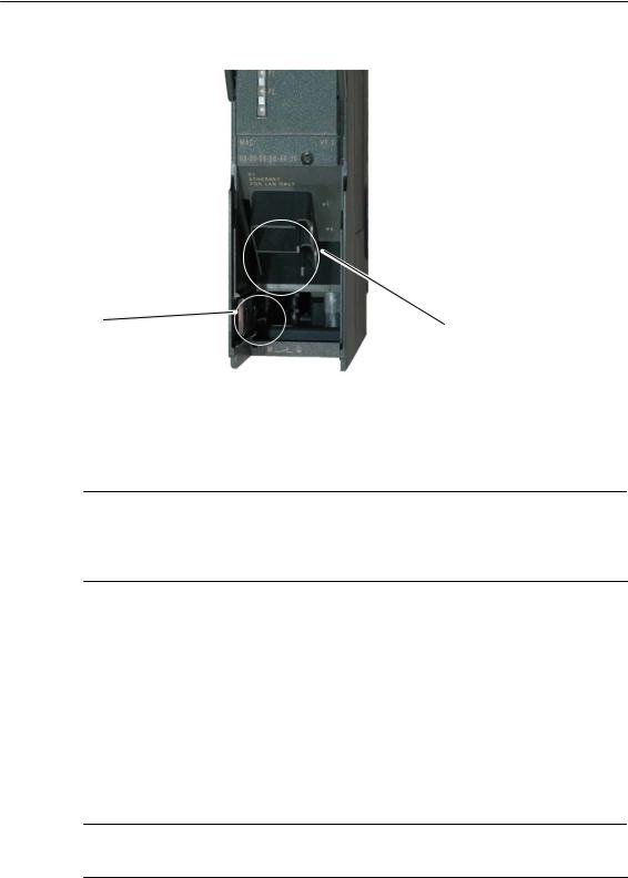
Use a screwdriver to set the slider. Note An Ethernet cable can also be inserted and removed with the power supply on. B3L−12 Attachment to Industrial Ethernet: 2 x 8-pin RJ-45 jack CP 343-1 Lean for Industrial Ethernet / Manual Part B3L Release 03/2007 C79000-G8976-C198-04… -
Page 13
The power unit for supplying the device must comply with NEC Class 2 as described by the National Electrical Code(r) (ANSI/NFPA 70). The power of all connected power units in total must correspond to a limited power source (LPS). CP 343-1 Lean for Industrial Ethernet / Manual Part B3L Release 03/2007 C79000-G8976-C198-04 B3L−13… -
Page 14: Displays
(not relevant for PROFINET IO data) S RUN: RUN mode S STOP: STOP mode S P1 / P2: Link status of Ethernet port 1 / port 2 B3L−14 DC5V RX/TX STOP CP 343-1 Lean for Industrial Ethernet / Manual Part B3L Release 03/2007 C79000-G8976-C198-04…
-
Page 15
SF(red) BF (red) (green) − − − Legend: (colored) on CP 343-1 Lean for Industrial Ethernet / Manual Part B3L Release 03/2007 C79000-G8976-C198-04 STOP CP Operating Mode (yellow) Starting up after power “ON” Stopped (STOP) with errors In this state, the CPU or intelligent modules in the rack remain accessible using PG functions. -
Page 16
Continuous data transfer at the port over Industrial Ethernet (for example PROFINET IO). (colored) flashing CP 343-1 Lean for Industrial Ethernet / Manual Part B3L Meaning “−” any Release 03/2007 C79000-G8976-C198-04… -
Page 17: Performance Data
Operator control and monitoring functions (HMI) S7 connections configured at one end LAN interface − data record length per protocol unit sending receiving CP 343-1 Lean for Industrial Ethernet / Manual Part B3L Release 03/2007 C79000-G8976-C198-04 Explanation / Values 12 maximum…
-
Page 18: Characteristics Of The Send/Receive Interface
<1 ms at <= 240 bytes per AG_SEND block call: <0.8 ms at <= 240 bytes CP 343-1 Lean for Industrial Ethernet / Manual Part B3L per AG_RECV block call: <1 ms at <= 240 bytes per AG_RECV block call: <0.8 ms at <= 240 bytes…
-
Page 19: Characteristic Data For Profinet Io
Execution time on the CPU 315−2DP (6ES7 315−2EG10−0AB0) Execution time on the CPU 317−2PN/DP (6ES7 317−2EJ10−0AB0) CP 343-1 Lean for Industrial Ethernet / Manual Part B3L Release 03/2007 C79000-G8976-C198-04 Explanation / Values per PNIO_SEND block call: < 1 ms at 240 bytes per PNIO_SEND block call: <…
-
Page 20: Configuring And Programming The Cp As A Profinet Io Device
B3L−20 Programming Write the user program for the PROFINET IO device SIMATIC S7 and download it to the SIMATIC S7 CPU. See Section 6.4 Commissioning CP 343-1 Lean for Industrial Ethernet / Manual Part B3L C79000-G8976-C198-04 Release 03/2007…
-
Page 21: Principle Of Data Exchange Over Profinet Io
In the CPU of the device, the IO data areas for input data and output data are transferred as an entire area to or from one of the data areas (DB, bit memory) including any gaps. CP 343-1 Lean for Industrial Ethernet / Manual Part B3L Release 03/2007 C79000-G8976-C198-04…
-
Page 22: Configuration
1. Take the required CP from the hardware catalog and insert the module in the SIMATIC 300 station. Figure 6-2 Inserting the CP in a SIMATIC Station in HW Config B3L−22 CP 343-1 Lean for Industrial Ethernet / Manual Part B3L Release 03/2007 C79000-G8976-C198-04…
-
Page 23
6. Select the option “Enable PROFINET IO device operation”. Figure 6-3 Setting the Device Name and the PROFINET IO Device Mode 7. Download the configuration data to the SIMATIC 300 station. CP 343-1 Lean for Industrial Ethernet / Manual Part B3L Release 03/2007 C79000-G8976-C198-04 B3L−23… -
Page 24: Assigning The Profinet Io Device To A Profinet Io Controller
2. If no PROFINET IO system exists, select the PROFINET IO controller (for example CP 343−1 EX30/GX21, CP 443−1 EX41, CPU 317−2 PN/DP) and insert a PROFINET IO system (menu “Insert” B3L−24 “PROFINET IO System”). » CP 343-1 Lean for Industrial Ethernet / Manual Part B3L Release 03/2007 C79000-G8976-C198-04…
-
Page 25
(O address). Figure 6-4 SIMATIC Station with PROFINET IO System with the CP as Device with Input (DI) and Output Modules (DO) CP 343-1 Lean for Industrial Ethernet / Manual Part B3L Release 03/2007 C79000-G8976-C198-04 “CP 343−1 Lean”. -
Page 26
IP address assigned by the PROFINET IO controller. If it is overwritten, any configured connections (S7, ISO-on-TCP, TCP) will no longer be established. B3L−26 CP 343-1 Lean for Industrial Ethernet / Manual Part B3L Release 03/2007 C79000-G8976-C198-04… -
Page 27: Programming
You will find the precise syntax of the FCs and the meaning of the block parameters in the chapter on FCs in the general part of the manual or in the online help for the block library in STEP 7. CP 343-1 Lean for Industrial Ethernet / Manual Part B3L Release 03/2007 C79000-G8976-C198-04…
-
Page 28: Initialization And Configuration
During initialization, the data of PNIO_SEND (FC11) is not evaluated and the data of PNIO_RECV (FC12) is initialized with default values. FC11 and FC12 transfer valid data only following the subsequent calls. B3L−28 CP 343-1 Lean for Industrial Ethernet / Manual Part B3L Release 03/2007 C79000-G8976-C198-04…
-
Page 29
FC11 and FC12 each have their own watchdog. Depending on the average CPU cycle time, the connection to the PROFINET IO controller is terminated if one of the two blocks is no longer called following the initialization phase. CP 343-1 Lean for Industrial Ethernet / Manual Part B3L Release 03/2007 C79000-G8976-C198-04… -
Page 30: B3L−30
Configuration of a PROFINET IO device in HW Config B3L−30 PNIO_SEND Output area: − Length: 7 bytes − available in DB11 − transferred with FC12 PNIO_RECV CP 343-1 Lean for Industrial Ethernet / Manual Part B3L Release 03/2007 C79000-G8976-C198-04 PNIO_RECV…
-
Page 31
M 70.1 STATUS := MW 72 CHECK_IOCS := M 70.2 SEND P#DB10.DBX0.0 BYTE 20 CP 343-1 Lean for Industrial Ethernet / Manual Part B3L Release 03/2007 C79000-G8976-C198-04 Explanation //PNIO_SEND block call //(transfer inputs to IO controller) //Module address from hardware configuration //No. -
Page 32
//Address for return parameter NDR //Address for return parameter ERROR //Address for return parameter STATUS //Address for return parameter CHECK_IOPS //Received data in DB11 (7 bytes) //Diagnostic information CP 343-1 Lean for Industrial Ethernet / Manual Part B3L Release 03/2007 C79000-G8976-C198-04… -
Page 33: Web Diagnostics
2. Start the Internet browser and enter the following address in the address line of your Internet browser: http:\<IP address of the CP> Web diagnostics opens with the “Start Page”. CP 343-1 Lean for Industrial Ethernet / Manual Part B3L Release 03/2007 C79000-G8976-C198-04 “Temporary Internet Files” group box «…
-
Page 34: Diagnostics Pages Of The Cp
Below the title bar of the start page, you can see the CP type (here: CP 343−1 CX10). Above the navigation panel to the left, you can see the module type (here: “SIMATIC S7 CP”). B3L−34 CP 343-1 Lean for Industrial Ethernet / Manual Part B3L Release 03/2007 C79000-G8976-C198-04…
-
Page 35: Start Page
Module type Name of the module type Status Operating mode Current mode of the CP: Starting RUN (CP in productive mode) Stopping STOP Stopped with error CP 343-1 Lean for Industrial Ethernet / Manual Part B3L Release 03/2007 C79000-G8976-C198-04 Function B3L−35…
-
Page 36: Identification
The “write data record” function is explained in detail in the general part A of the manual in the description of the FCs for PROFINET IO. B3L−36 Function CP 343-1 Lean for Industrial Ethernet / Manual Part B3L Release 03/2007 C79000-G8976-C198-04…
-
Page 37: Rack Configuration
The last column “LED Status” contains more information. Module name Name of the module configured in HW Config Order number Order number of the module CP 343-1 Lean for Industrial Ethernet / Manual Part B3L Release 03/2007 C79000-G8976-C198-04 Function B3L−37…
-
Page 38
The number of type of the LEDs depends on the particular module type. You will find an explanation of the significance of the LEDs in the documentation for the particular module. B3L−38 Function CP 343-1 Lean for Industrial Ethernet / Manual Part B3L Release 03/2007 C79000-G8976-C198-04… -
Page 39: Diagnostic Buffer
Displays the diagnostic buffer entry (entries only in English) Details: “no. of the event” Event ID Event ID of the diagnostic buffer entry Text of the event entry CP 343-1 Lean for Industrial Ethernet / Manual Part B3L Release 03/2007 C79000-G8976-C198-04 Function B3L−39…
-
Page 40: Industrial Ethernet
Displays the current network properties (transmission rate and direction). Possible values: 10 Mbps half duplex 10 Mbps full duplex 100 Mbps half duplex 100 Mbps full duplex B3L−40 Function CP 343-1 Lean for Industrial Ethernet / Manual Part B3L Release 03/2007 C79000-G8976-C198-04…
-
Page 41
Number of the port used for the UDP connection Partner port Number of the port on the partner used for the UDP connection CP 343-1 Lean for Industrial Ethernet / Manual Part B3L Release 03/2007 C79000-G8976-C198-04 Function Function Function B3L−41… -
Page 42: Profinet Io
PROFINET IO mode of the CP (here: PROFINET IO device): PROFINET IO controller PROFINET IO device No PROFINET IO configuration Device name Device name IP address IP address of the device B3L−42 Function CP 343-1 Lean for Industrial Ethernet / Manual Part B3L Release 03/2007 C79000-G8976-C198-04…
-
Page 43
(the blocks are not called or not correctly called) Assigned PNIO controller Device name Device name of the assigned controller IP address IP address of the controller CP 343-1 Lean for Industrial Ethernet / Manual Part B3L Release 03/2007 C79000-G8976-C198-04 Function B3L−43… -
Page 44: Compatibility With Predecessor Products
For new user programs, please make sure that you always use the latest block versions. You will find information on the latest block version and links to download the current blocks on the Internet: http://www4.ad.siemens.de/WW/news/en/8797900 B3L−44 CP 343-1 Lean for Industrial Ethernet / Manual Part B3L Release 03/2007 C79000-G8976-C198-04…
-
Page 45
When replacing an older module with the module described here, keep to the steps outlined below: Table 8-1 Originally configured module 6GK7 343−1CX00−0XE0 CP 343-1 Lean for Industrial Ethernet / Manual Part B3L Release 03/2007 C79000-G8976-C198-04 Configuration Steps Case a: Configuration unchanged… -
Page 46: Further Notes On Operation
In STEP 7 / NCM Diagnostics with Operating Mode S Factory defaults reset In STEP 7 / NCM Diagnostics with Operating Mode Defaults B3L−46 Clear/Reset » Clear/Reset Module » Reset to Factory » CP 343-1 Lean for Industrial Ethernet / Manual Part B3L C79000-G8976-C198-04 Release 03/2007…
-
Page 47: Working With Fast Ethernet − Automatic Switchover
CP, “Port Parameters” tab. Autocrossing The automatic setting also includes an “autocrossing” mechanism. With autocrossing, you can connect network components and end devices using either crossover or straight−through cables. CP 343-1 Lean for Industrial Ethernet / Manual Part B3L Release 03/2007 C79000-G8976-C198-04 B3L−47…
-
Page 48
“100 Mbps − half duplex”. Reason: Due to the fixed setting, no autonegotiation response is possible; the connected partner recognizes the 100 Mbps with autosensing but nevertheless remains in half duplex. B3L−48 CP 343-1 Lean for Industrial Ethernet / Manual Part B3L Release 03/2007 C79000-G8976-C198-04… -
Page 49: Snmp Agent
S Write access is permitted only for the following MIB objects: sysContact, sysLocation and sysName; For security reasons, only read access is permitted for all other MIB objects. S Traps are not supported by the CP. CP 343-1 Lean for Industrial Ethernet / Manual Part B3L Release 03/2007 C79000-G8976-C198-04 B3L−49…
-
Page 50: Possible Security Gaps On Standard It Interfaces / Preventing Illegal Access
If you have questions on the use of firewall systems and IT security, please contact your local Siemens office or representative. You will find the address in the SIMATIC catalog IK PI or on the Internet at http://www.automation.siemens.com/net…
-
Page 51: B3L−51
The following local port numbers are reserved; You should not use these for other purposes in the connection configuration. Table 9-1 Reserved Port Numbers Protocol CP 343-1 Lean for Industrial Ethernet / Manual Part B3L Release 03/2007 C79000-G8976-C198-04 Port number 20, 21…
-
Page 52: Restart After Detection Of A Duplicate Ip Address In The Network
GSDML file You will find the GSDML file for the CP described here on the Internet under the following entry ID: http://support.automation.siemens.com/WW/view/en/19698639/133100 B3L−52 > “FAQ” tab CP 343-1 Lean for Industrial Ethernet / Manual Part B3L Release 03/2007 C79000-G8976-C198-04…
-
Page 53: 10 How To Load New Firmware
In this case, turn the station off and on again and repeat the download. CP 343-1 Lean for Industrial Ethernet / Manual Part B3L Release 03/2007 C79000-G8976-C198-04…
-
Page 54: B3L−54
CL. 1, Zone 2, GP.IIC. T.. Ta:.. AS/NZS 2064 (Class A). EN 61000−6−2, EN 61000−6−4 (replaces EN 50081−2) EN60079−15 II 3 G EEx nA II T.. KEMA 03 ATEX 1228 X CP 343-1 Lean for Industrial Ethernet / Manual Part B3L C79000-G8976-C198-04 Release 03/2007…
-
Page 55
Data” /1/ in the chapter “General Technical Specifications” applies to the CP. S Electromagnetic compatibility S Transportation and storage conditions S Mechanical and climatic ambient conditions S Insulation tests, class of protection and degree of protection CP 343-1 Lean for Industrial Ethernet / Manual Part B3L Release 03/2007 C79000-G8976-C198-04 B3L−55… -
Page 56: Release 03/2007 C79000-G8976-C198-04
11 Technical Specifications CP 343-1 Lean for Industrial Ethernet / Manual Part B3L B3L−56 Release 03/2007 C79000-G8976-C198-04…
Краткое содержание страницы № 1
SIMATIC NET
S7-CPs for Industrial Ethernet
Manual Part B3L
CP 343-1 Lean
6GK7 343 −1CX10 −0XE0 as of hardware version 2, as of firmware version V2.0
for SIMATIC S7 −300 / C7 −300
LED displays
TP port:
2 x 8 −pin RJ −45 socket
(beneath the front panel)
X = Placeholder for hardware
version
Release 03/2007
C79000-G8976-C198-04
Краткое содержание страницы № 2
Notes on the Product Notes on the Product Product Names This description contains information on the following product CP 343 −1 Lean Order number 6GK7 343 −1CX10 −0XE0 as of hardware version 2 and firmware version V2.0 for SIMATIC S7 −300 / C7 −300 Note In this document, the term CP is used instead of the full product name. Printed Product Information Supplied with the Product Note All the notices in the Product Information Bulletin shipped with this device must be adhered to. Compatibility w
Краткое содержание страницы № 3
Contents Contents Contents − Part A Ethernet CPs − General information . . . . . . . . . . . . . . . . . . . see general part Note Please remember that Part A of the device manual also belongs to the description of the CP. Among other things, it contains explanations of the safety notices and general information that applies to all S7 CPs for Industrial Ethernet. You will find the references in this Part B of the manual /…/ in the Appendix of the general Part A of the manual. The following ver
Краткое содержание страницы № 4
Contents 6.4.2 Initialization and Configuration . . . . . . . . . . . . . . . . . . . . . . . . . . . . . . . . . B3L −28 6.5 Example of Configuration and Programming . . . . . . . . . . . . . . . . . . . . . B3L −30 7 Web Diagnostics . . . . . . . . . . . . . . . . . . . . . . . . . . . . . . . . . . . . . . . . . . . . . . . . . . . . . . . B3L−33 7.1 Requirements and Use . . . . . . . . . . . . . . . . . . . . . . . . . . . . . . . . . . . . . . . . B3L −33 7.2 Diagnostics Pages of the CP . .
Краткое содержание страницы № 5
1 Properties / Services 1 Properties / Services Application The CP 343 −1 Lean communications processor is designed for operation in a SIMATIC S7-300 programmable logic controller. It allows attachment of the S7 −300 to Industrial Ethernet and supports PROFINET IO. A 2-port switch with autocrossing, autonegotiation and autosensing was integrated in the CP for simple integration in a line or for attaching a further Ethernet device. Services The CP supports the following communication services:
Краткое содержание страницы № 6
1 Properties / Services Time-of-day synchronization over Industrial Ethernet using the following configurable modes: − SIMATIC mode The CP receives MMS time frames and synchronizes its local time and the time of the CPU (accuracy approx. +/ − 1 second); or − NTP mode (NTP: Network Time Protocol) The CP sends time-of-day queries at regular intervals to an NTP server and synchronizes its local time of day and the time of the CPU (accuracy approx. +/ − 1 second). Time of day for the diagnostic
Краткое содержание страницы № 7
1 Properties / Services Configuration It is possible to download the configuration data to the CP over MPI or LAN/Industrial Ethernet. You require STEP 7 with NCM S7 for Industrial Ethernet (NCM IE) with the following version: Table 1-1 Version STEP 7 / NCM IE Functions of the CP V5.2 or higher The range of functions of the CP 343 −1 Lean (CX00) can be configured. V5.4 or higher Requirement for configuring the full functionality of the CP 343 −1 Lean (CX10 with firmware V1.0) including PROFINE
Краткое содержание страницы № 8
2 Requirements for Use 2 Requirements for Use General Operation The CP can be operated in the following device families: S7 −300 stations with the CPU types − Standard − Compact − Modular C7 control systems in C7 packaging system The following tables show the devices with which the CP can be operated with this range of functions: Notice The tables list the CPUs and devices approved at the time of printing this manual. S7-300 CPUs or C7 or C7 control systems approved later and not listed in
Краткое содержание страницы № 9
2 Requirements for Use Table 2-1 Use of the CP with S7 −300 CPU Order Number CPU 314 IFM 6ES7 314 −5AE03 −0AB0 6ES7 314 −5AE10 −0AB0 CPU 314C −2 DP 6ES7 314 −6CF00 −0AB0 6ES7 314 −6CF02 −0AB0 6ES7 314 −6CG03 −0AB0 CPU 314C −2 PtP 6ES7 314 −6BF00 −0AB0 6ES7 314 −6BF01 −0AB0 6ES7 314 −6BF02 −0AB0 6ES7 314 −6BG03 −0AB0 CPU 315 6ES7 315 −1AF03 −0AB0 CPU 315 −2 DP 6ES7 315 −2AF03 −0AB0 6ES7 315 −2AG10 −0AB0 CPU 315 −2 PN/DP 6ES7 315 −2EG10 −0AB0 6ES7 315 −2EH13 −0AB0 CPU 315F −2 DP 6ES7 315 −6FF01 −0
Краткое содержание страницы № 10
2 Requirements for Use Table 2-2 Use of the CP in C7 Control Systems C7 Order Number C7 −613 6ES7 613 −1CA01 −0AE03 6ES7 613 −1CA02 −0AE3 C7 −633 DP 6ES7 633 −2BF02 −0AE03 C7 −635 Keys 6ES7 635 −2EC01 −0AE3 6ES7 635 −2EC02 −0AE3 C7 −635 Touch 6ES7 635 −2EB01 −0AE03 6ES7 635 −2EB02 −0AE3 C7 −636 Keys 6ES7 636 −2EC00 −0AE03 6ES7 636 −2EC00 −0AE3 C7 −636 Touch 6ES7 636 −2EB00 −0AE3 CP 343-1 Lean for Industrial Ethernet / Manual Part B3L B3L −10 Release 03/2007 C79000-G8976-C198-04
Краткое содержание страницы № 11
3 Installation and Commissioning 3 Installation and Commissioning 3.1 Procedure / Steps Step Explanation / Meaning 1. Install the CP on the S7 standard rail. Slots 4 to 11 are permitted for the CP in racks 0 to 3 (connected by IM 360/361). 2. Establish the connection via the enclosed bus connector to the backplane bus. Proceed as in the sections dealing with setup and wiring, described in detail in /1/. Note The CP cannot be used in an extension rack that is connected via the IM 365! Reason: T
Краткое содержание страницы № 12
3 Installation and Commissioning Attachment to Industrial Slider for setting Ethernet: the chassis 2 x 8-pin RJ-45 jack ground contact Figure 3-1 Connectors of a CP 343 −1 Lean with the Front Panel Open Ground/Chassis Ground Concept Notice Please note the instructions regarding the grounding and chassis ground concept in the SIMATIC S7 installation guides; see “SIMATIC S7 Programmable Controller S7 −300 − Installation and Hardware: Installation Manual” /1/. Behind the hinged panel on the left of
Краткое содержание страницы № 13
3 Installation and Commissioning Note The hinged front panel must be kept closed during operation. The module must be installed so that its upper and lower ventilation slits are not covered, allowing adequate ventilation. Warning ! When used under hazardous conditions (zone 2), the devices must be installed in an enclosure. To comply with ATEX100a (EN 60079 −15), this enclosure must meet the requirements of at least IP54 in compliance with EN 60529. WARNING − EXPLOSION HAZARD: DO NOT DISCONNECT
Краткое содержание страницы № 14
4 Displays 4 Displays The display on the front panel consists of 8 LEDs that indicate the operating mode and the communication status. Front panel: SF BF DC5V RX/TX P1 RUN P2 STOP The LEDs have the following meaning: SF: Group error BF: Bus fault PROFINET IO DCV5: DC 5 V power supply via the backplane bus (green = OK) RX/TX: Acyclic data exchange, for example Send/Receive (not relevant for PROFINET IO data) RUN: RUN mode STOP: STOP mode P1 / P2: Link status of Ethernet port 1 / p
Краткое содержание страницы № 15
4 Displays LEDs for displaying the mode The different combinations of the LEDs on the front panel indicate the status: SF(red) BF (red) RUN STOP CP Operating Mode (green) (yellow) Starting up after power “ON” or Stopped (STOP) with errors − In this state, the CPU or intelligent modules in the rack remain accessible using PG functions. Starting up (STOP->RUN) Running (RUN) Stopping (RUN->STOP) Stopped (STOP) In the STOP mode configuring and performing diagnostics on the CP remain possible. −
Краткое содержание страницы № 16
4 Displays LEDs for displaying the CP communication status In addition to the LEDs that signal the CP state, the following LEDs provide information about the status of the CP interface to Industrial Ethernet. Table 4-1 LED Display Meaning RX/TX (green) The CP is sending/receiving over Industrial Ethernet Note: Sending / receiving over PROFINET IO is not signaled here. P1 / P2 Port has no connection to (green / yellow) Industrial Ethernet. green Existing connection over port to Industrial Ethern
Краткое содержание страницы № 17
5 Performance Data 5 Performance Data 5.1 Number of Possible Connections over Ethernet Table 5-1 Characteristic Explanation / Values Permitted number of simultaneous connections in 12 maximum total over Industrial Ethernet Example of Maximum Load You can operate: 4 S7 connections 4 ISO-on-TCP connections 2 TCP connections 2 UDP connections Also: Further TCP connections for Web diagnostics 1 PROFINET connection to a PROFINET IO controller 5.2 Characteristic Data for S7 Communication Table
Краткое содержание страницы № 18
5 Performance Data 5.3 Characteristics of the SEND/RECEIVE Interface Table 5-3 Characteristic Explanation / Values Number of ISO-on-TCP connections + TCP 8 maximum connections + UDP connections in total Notes: All UDP connections are also possible in the multicast mode Free UDP connections are supported by the CP. Max. data length for blocks AG_SEND (V4.0 and AG_SEND and AG_RECV allow the transfer of higher) and AG_RECV (V4.0 and higher) data fields of between 1 and 240 bytes. 1 to 8192
Краткое содержание страницы № 19
5 Performance Data 5.4 Characteristic Data for PROFINET IO CP as PROFINET IO device The CP supports the following maximum configuration as a PROFINET IO device: Table 5-5 Explanation / Values Characteristic Size of the input area of the PROFINET IO device 512 bytes max. Size of the output area of the PROFINET IO device 512 bytes max. Size of the IO data area per submodule in a PROFINET IO device Inputs 240 bytes Outputs 240 bytes Size of the consistency area for a submodule 240 bytes Maximu
Краткое содержание страницы № 20
6 Configuring and Programming the CP as a PROFINET IO Device 6 Configuring and Programming the CP as a PROFINET IO Device “Intelligent” PROFINET IO Device A CP 343 −1 Lean can be configured so that the SIMATIC 300 station can be addressed as a PROFINET IO device. Due to the programmability of SIMATIC 300 stations, they are also known as “intelligent” PROFINET IO devices because: Process data can be processed before it is forwarded to the PROFINET IO controller or after it has been received fro

SIMATIC NET
S7-CPs for Industrial Ethernet
Manual Part B3L
CP 343-1 Lean
6GK7 343−1CX10−0XE0
as of hardware version 2, as of firmware version V2.0
for SIMATIC S7−300 / C7−300
Release 03/2007
C79000-G8976-C198-04
TP port:
2 x 8−pin RJ−45 socket
(beneath the front panel)
LED displays
X = Placeholder for hardware
version

SIMATIC NET
S7-CPs for Industrial Ethernet
Manual Part B3L
CP 343-1 Lean
6GK7 343−1CX10−0XE0 as of hardware version 2, as of firmware version V2.0 for SIMATIC S7−300 / C7−300
LED displays
TP port:
2 x 8−pin RJ−45 socket (beneath the front panel)
X = Placeholder for hardware version
Release 03/2007
C79000-G8976-C198-04

Notes on the Product
Notes on the Product
Product Names
This description contains information on the following product
SCP 343−1 Lean
Order number 6GK7 343−1CX10−0XE0
as of hardware version 2 and firmware version V2.0 for SIMATIC S7−300 / C7−300
Note
In this document, the term CP is used instead of the full product name.
Printed Product Information Supplied with the Product
Note
All the notices in the Product Information Bulletin shipped with this device must be adhered to.
Compatibility with the Previous Version
Note
Due to the increased functionality and restrictions, pay particular attention to the notes in Chapter 8 of this manual.
Address label: Unique MAC address preset for the CP
The CP ships with a factory-set MAC address.
To ensure a unique address assignment, we recommend that you use this factory set MAC address when configuring the module!
—
|
B3L−2 |
CP 343-1 Lean for Industrial Ethernet / Manual Part B3L |
|
Release 03/2007 |
C79000-G8976-C198-04

Contents
Contents
Contents − Part A
Ethernet CPs − General information . . . . . . . . . . . . . . . . . . . see general part
Note
Please remember that Part A of the device manual also belongs to the description of the CP. Among other things, it contains explanations of the safety notices and general information that applies to all S7 CPs for Industrial Ethernet.
You will find the references in this Part B of the manual /…/ in the Appendix of the general Part A of the manual.
The following version of the manual Part A of the manual belongs to this version of Part B: Release 01/2007
You can download the general Part from the Internet:
http://www4.ad.siemens.de/view/cs/en/8777865
Contents − Part B3L
|
1 |
Properties / Services . . . . . . . . . . . . . . . . . . . . . . . . . . . . . . . . . . . . . . . . . . . . . . . . . . . |
B3L−5 |
|
|
2 |
Requirements for Use . . . . . . . . . . . . . . . . . . . . . . . . . . . . . . . . . . . . . . . . . . . . . . . . . . |
B3L−8 |
|
|
3 |
Installation and Commissioning . . . . . . . . . . . . . . . . . . . . . . . . . . . . . . . . . . . . . . . . . |
B3L−11 |
|
|
3.1 |
Procedure / Steps . . . . . . . . . . . . . . . . . . . . . . . . . . . . . . . . . . . . . . . . . . . . |
B3L−11 |
|
|
4 |
Displays . . |
. . . . . . . . . . . . . . . . . . . . . . . . . . . . . . . . . . . . . . . . . . . . . . . . . . . . . . . . . . . . . |
B3L−14 |
|
5 |
Performance Data . . . . . . . . . . . . . . . . . . . . . . . . . . . . . . . . . . . . . . . . . . . . . . . . . . . . . . |
B3L−17 |
|
|
5.1 |
Number of Possible Connections over Ethernet . . . . . . . . . . . . . . . . . . . |
B3L−17 |
|
|
5.2 |
Characteristic Data for S7 Communication . . . . . . . . . . . . . . . . . . . . . . . |
B3L−17 |
|
|
5.3 |
Characteristics of the SEND/RECEIVE Interface . . . . . . . . . . . . . . . . . |
B3L−18 |
|
|
5.4 |
Characteristic Data for PROFINET IO . . . . . . . . . . . . . . . . . . . . . . . . . . . |
B3L−19 |
|
|
6 |
Configuring and Programming the CP as a PROFINET IO Device . . . . . . . . . . |
B3L−20 |
|
|
6.1 |
Overview of the Preparatory Steps . . . . . . . . . . . . . . . . . . . . . . . . . . . . . |
B3L−20 |
|
|
6.2 |
Principle of Data Exchange over PROFINET IO . . . . . . . . . . . . . . . . . . |
B3L−21 |
|
|
6.3 |
Configuration . . . . . . . . . . . . . . . . . . . . . . . . . . . . . . . . . . . . . . . . . . . . . . . . |
B3L−22 |
|
|
6.3.1 |
Installing the CP and Specifying it as PROFINET IO Device . . . . . . . . |
B3L−22 |
|
|
6.3.2 |
Assigning the PROFINET IO Device to a PROFINET IO Controller . . |
B3L−24 |
|
|
6.4 |
Programming . . . . . . . . . . . . . . . . . . . . . . . . . . . . . . . . . . . . . . . . . . . . . . . . |
B3L−27 |
|
|
6.4.1 |
Interface for Programming on the PROFINET IO Device . . . . . . . . . . . |
B3L−27 |
|
|
CP 343-1 Lean for Industrial Ethernet / Manual Part B3L |
B3L−3 |
||
|
Release 03/2007 |
C79000-G8976-C198-04

Contents
|
6.4.2 |
Initialization and Configuration . . . . . . . . . . . . . . . . . . . . . . . . . . . . . . . . . |
B3L−28 |
|
|
6.5 |
Example of Configuration and Programming . . . . . . . . . . . . . . . . . . . . . |
B3L−30 |
|
|
7 |
Web Diagnostics . . . . . . . . . . . . . . . . . . . . . . . . . . . . . . . . . . . . . . . . . . . . . . . . . . . . . . . |
B3L−33 |
|
|
7.1 |
Requirements and Use . . . . . . . . . . . . . . . . . . . . . . . . . . . . . . . . . . . . . . . . |
B3L−33 |
|
|
7.2 |
Diagnostics Pages of the CP . . . . . . . . . . . . . . . . . . . . . . . . . . . . . . . . . . . |
B3L−34 |
|
|
7.2.1 |
Start Page . . . . . . . . . . . . . . . . . . . . . . . . . . . . . . . . . . . . . . . . . . . . . . . . . . . |
B3L−35 |
|
|
7.2.2 |
Identification . . . . . . . . . . . . . . . . . . . . . . . . . . . . . . . . . . . . . . . . . . . . . . . . . |
B3L−36 |
|
|
7.2.3 |
Rack Configuration . . . . . . . . . . . . . . . . . . . . . . . . . . . . . . . . . . . . . . . . . . . |
B3L−37 |
|
|
7.2.4 |
Diagnostic Buffer . . . . . . . . . . . . . . . . . . . . . . . . . . . . . . . . . . . . . . . . . . . . . |
B3L−39 |
|
|
7.2.5 |
Industrial Ethernet . . . . . . . . . . . . . . . . . . . . . . . . . . . . . . . . . . . . . . . . . . . . |
B3L−40 |
|
|
7.2.6 |
PROFINET IO . . . . . . . . . . . . . . . . . . . . . . . . . . . . . . . . . . . . . . . . . . . . . . . |
B3L−42 |
|
|
8 |
Compatibility with Predecessor Products . . . . . . . . . . . . . . . . . . . . . . . . . . . . . . . . |
B3L−44 |
|
|
8.1 |
Extended Functionality . . . . . . . . . . . . . . . . . . . . . . . . . . . . . . . . . . . . . . . . |
B3L−44 |
|
|
8.2 |
Replacing Older Modules / Replacing Faulty Modules . . . . . . . . . . . . . |
B3L−44 |
|
|
9 |
Further Notes on Operation . . . . . . . . . . . . . . . . . . . . . . . . . . . . . . . . . . . . . . . . . . . . . |
B3L−46 |
|
|
9.1 |
Memory Reset . . . . . . . . . . . . . . . . . . . . . . . . . . . . . . . . . . . . . . . . . . . . . . . |
B3L−46 |
|
|
9.2 |
Working with Fast Ethernet − automatic switchover . . . . . . . . . . . . . . . |
B3L−47 |
|
|
9.3 |
SNMP Agent . . . . . . . . . . . . . . . . . . . . . . . . . . . . . . . . . . . . . . . . . . . . . . . . |
B3L−49 |
9.4Possible Security Gaps on Standard IT Interfaces / Preventing
|
Illegal Access . . . . . . . . . . . . . . . . . . . . . . . . . . . . . . . . . . . . . . . . . . . . . . . . |
B3L−50 |
|
|
9.5 |
Influence of MPI on Connections via Industrial Ethernet . . . . . . . . . . . |
B3L−50 |
|
9.6 |
Special Features of IP Configuration . . . . . . . . . . . . . . . . . . . . . . . . . . . . |
B3L−51 |
|
9.7 |
Reserved Port Numbers . . . . . . . . . . . . . . . . . . . . . . . . . . . . . . . . . . . . . . . |
B3L−51 |
|
9.8 |
Restart after Detection of a Duplicate IP Address in the Network . . . . |
B3L−52 |
|
9.9 |
Obtaining the IP Address over DHCP − CP STOP on Expiry of |
|
|
the Lease . . . . . . . . . . . . . . . . . . . . . . . . . . . . . . . . . . . . . . . . . . . . . . . . . . . |
B3L−52 |
|
|
9.10 |
Other information available about the CP . . . . . . . . . . . . . . . . . . . . . . . . |
B3L−52 |
|
10 How to Load New Firmware . . . . . . . . . . . . . . . . . . . . . . . . . . . . . . . . . . . . . . . . . . . . |
B3L−53 |
|
|
11 Technical Specifications . . . . . . . . . . . . . . . . . . . . . . . . . . . . . . . . . . . . . . . . . . . . . . . |
B3L−54 |
|
B3L−4 |
CP 343-1 Lean for Industrial Ethernet / Manual Part B3L |
|
Release 03/2007 |
C79000-G8976-C198-04

1 Properties / Services
1 Properties / Services
Application
The CP 343−1 Lean communications processor is designed for operation in a SIMATIC S7-300 programmable logic controller. It allows attachment of the S7−300 to Industrial Ethernet and supports PROFINET IO.
A 2-port switch with autocrossing, autonegotiation and autosensing was integrated in the CP for simple integration in a line or for attaching a further Ethernet device.
Services
The CP supports the following communication services:
SPROFINET IO device
Integration of the SIMATIC S7−300 programmable controller over the CP as intelligent PROFINET IO device.
SS7 communication and PG/OP communication
−PG functions (including routing)
−Operator control and monitoring functions (HMI)
−Server for data exchange on S7 connections configured at one end only without communication blocks on the S7-300 / C7-300 station
SS5 compatible communication with
−SEND/RECEIVE interface over ISO-on-TCP, TCP and UDP connections
−Multicast over UDP connection
The multicast mode is made possible by selecting a suitable IP address when configuring connections.
−FETCH/WRITE services (server; corresponding to S5 protocol) via ISO-on-TCP connections and TCP connections;
The addressing mode can be configured for FETCH/WRITE access as the S7 or S5 addressing mode.
−LOCK/UNLOCK with FETCH/WRITE services;
|
CP 343-1 Lean for Industrial Ethernet / Manual Part B3L |
B3L−5 |
|
Release 03/2007 |
C79000-G8976-C198-04

1 Properties / Services
STime-of-day synchronization over Industrial Ethernet using the following configurable modes:
− SIMATIC mode
The CP receives MMS time frames and synchronizes its local time and the time of the CPU (accuracy approx. +/− 1 second);
or
−NTP mode (NTP: Network Time Protocol)
The CP sends time-of-day queries at regular intervals to an NTP server and synchronizes its local time of day and the time of the CPU (accuracy approx. +/− 1 second).
STime of day for the diagnostic buffer
If a time master exists (using the NTP or SIMATIC mode), the time for the CP-internal diagnostic buffer is synchronized over the LAN (accuracy approx. +/− 10 ms)
SAddressing using a factory-set MAC address
The CP can be reached over the default MAC address to allow an IP address to be assigned.
SSNMP Agent
The CP supports data queries over SNMP in version V1 (Simple Network Management Protocol) according to the MIB II and LLDP MIB standard.
You will find more information on MIB in the manual “Commissioning PC Stations” on the SIMATIC NET Manual Collection or at the following SIMATIC NET Internet page:
http://support.automation.siemens.com/WW/view/en/15177711
SIP configuration
You can configure how and with which method the CP is assigned the IP address, the subnet mask and the address of a default router.
It is also possible, as an alternative, to assign the connection configuration to the CP using STEP 7 or using a block interface in the user program (FB55: IP_CONFIG) (see /Part A/).
SWeb diagnostics
With the aid of Web diagnostics, you can read out the diagnostic data from a station connected over the CP to a PG/PC with an Internet browser.
|
B3L−6 |
CP 343-1 Lean for Industrial Ethernet / Manual Part B3L |
|
Release 03/2007 |
C79000-G8976-C198-04

1 Properties / Services
Configuration
It is possible to download the configuration data to the CP over MPI or LAN/Industrial Ethernet. You require STEP 7 with NCM S7 for Industrial Ethernet (NCM IE) with the following version:
Table 1-1
|
Version STEP 7 / NCM IE |
Functions of the CP |
|
V5.2 or higher |
The range of functions of the CP 343−1 Lean (CX00) can be |
|
configured. |
|
|
V5.4 or higher |
Requirement for configuring the full functionality of the |
|
CP 343−1 Lean (CX10 with firmware V1.0) including PROFINET |
|
|
IO. |
|
|
V5.4 Service Pack 2 *) |
Requirement for configuring the full functionality of the |
|
CP 343−1 Lean (CX10 with firmware V2.0) including Web |
|
|
diagnostics. |
|
*) To use the CP with V5.4 Service Pack 1, you will need to install Hotfix 2, the corresponding hardware update and a block setup. You will find more information at the following Internet page: http://www4.ad.siemens.de/WW/news/en/24463868
Programming − Using Blocks
For some communications services, there are pre-programmed blocks (FCs/FBs) available as the interface in your STEP 7 user program.
You will find a detailed description of these blocks in the NCM S7 for Ethernet manuals.
Notice
We recommend that you always use the latest block versions for all module types.
You will find information on the latest block version and links to download the current blocks in our Customer Support area on the Internet:
http://www4.ad.siemens.de/WW/news/en/8797900
If you are using older block types, this recommendation only applies if you also have the latest firmware version.
You will find further information and Internet addresses in the Preface of the General Part of this manual.
|
CP 343-1 Lean for Industrial Ethernet / Manual Part B3L |
B3L−7 |
|
Release 03/2007 |
C79000-G8976-C198-04

2 Requirements for Use
2 Requirements for Use
General Operation
The CP can be operated in the following device families:
SS7−300 stations with the CPU types
−Standard
−Compact
−Modular
SC7 control systems in C7 packaging system
The following tables show the devices with which the CP can be operated with this range of functions:
Notice
The tables list the CPUs and devices approved at the time of printing this manual. S7-300 CPUs or C7 or C7 control systems approved later and not listed in the table also support the range of functions described here.
Table 2-1 Use of the CP with S7−300
|
CPU |
Order Number |
|
|
CPU 312 |
6ES7 312−1AD10−0AB0 |
|
|
6ES7 312−1AE13−0AB0 |
||
|
CPU 312C |
6ES7 312−5BD01−0AB0 |
|
|
6ES7 312−5BE03−0AB0 |
||
|
CPU 312 IFM |
6ES7 312−5AC02−0AB0 |
|
|
CPU 313 |
6ES7 313−1AD03−0AB0 |
|
|
CPU 313C |
6ES7 313−5BE00−0AB0 |
|
|
6ES7 313−5BE01−0AB0 |
||
|
6ES7 313−5BF03−0AB0 |
||
|
CPU 313C−2 DP |
6ES7 313−6CE00−0AB0 |
|
|
6ES7 313−6CE01−0AB0 |
||
|
6ES7 313−6CF03−0AB0 |
||
|
CPU 313C−2 PtP |
6ES7 313−6BE00−0AB0 |
|
|
6ES7 313−6BE01−0AB0 |
||
|
6ES7 313−6BF03−0AB0 |
||
|
CPU 314 |
6ES7 314−6AE01−0AB0 |
|
|
6ES7 314−6AE02−0AB0 |
||
|
6ES7 314−6AE03−0AB0 |
||
|
6ES7 314−6AE04−0AB0 |
||
|
6ES7 314−1AF10−0AB0 |
||
|
6ES7 314−1AF11−0AB0 |
||
|
6ES7 314−1AG13−0AB0 |
||
|
B3L−8 |
CP 343-1 Lean for Industrial Ethernet / Manual Part B3L |
|
|
Release 03/2007 |
C79000-G8976-C198-04

2 Requirements for Use
Table 2-1 Use of the CP with S7−300
|
CPU |
Order Number |
|
CPU 314 IFM |
6ES7 314−5AE03−0AB0 |
|
6ES7 314−5AE10−0AB0 |
|
|
CPU 314C−2 DP |
6ES7 314−6CF00−0AB0 |
|
6ES7 314−6CF02−0AB0 |
|
|
6ES7 314−6CG03−0AB0 |
|
|
CPU 314C−2 PtP |
6ES7 314−6BF00−0AB0 |
|
6ES7 314−6BF01−0AB0 |
|
|
6ES7 314−6BF02−0AB0 |
|
|
6ES7 314−6BG03−0AB0 |
|
|
CPU 315 |
6ES7 315−1AF03−0AB0 |
|
CPU 315−2 DP |
6ES7 315−2AF03−0AB0 |
|
6ES7 315−2AG10−0AB0 |
|
|
CPU 315−2 PN/DP |
6ES7 315−2EG10−0AB0 |
|
6ES7 315−2EH13−0AB0 |
|
|
CPU 315F−2 DP |
6ES7 315−6FF01−0AB0 |
|
CPU 315F−2 PN/DP |
6ES7 315−2FH10−0AB0 |
|
6ES7 315−2FH13−0AB0 |
|
|
CPU 316 |
6ES7 316−1AG00−0AB0 |
|
CPU 316−2 DP |
6ES7 316−2AG00−0AB0 |
|
CPU 317−2 DP |
6ES7 317−2AJ10−0AB0 |
|
CPU 317−2 PN/DP |
6ES7 317−2EJ10−0AB0 |
|
6ES7 317−2EK13−0AB0 |
|
|
CPU 317F−2 DP |
6ES7 317−6FF00−0AB0 |
|
6ES7 317−6FF03−0AB0 |
|
|
CPU 317F−2 PN/DP |
6ES7 317−2FJ10−0AB0 |
|
6ES7 317−2FK13−0AB0 |
|
|
CPU 318−2 |
6ES7 318−2AJ00−0AB0 |
|
CPU 319−3 PN/DP |
6ES7 318−3EL00−0AB0 |
|
CPU 614 |
6ES7 614−1AH03−0AB3 |
|
CP 343-1 Lean for Industrial Ethernet / Manual Part B3L |
B3L−9 |
|
Release 03/2007 |
C79000-G8976-C198-04

2 Requirements for Use
Table 2-2 Use of the CP in C7 Control Systems
|
C7 |
Order Number |
|
C7−613 |
6ES7 613−1CA01−0AE03 |
|
6ES7 613−1CA02−0AE3 |
|
|
C7−633 DP |
6ES7 633−2BF02−0AE03 |
|
C7−635 Keys |
6ES7 635−2EC01−0AE3 |
|
6ES7 635−2EC02−0AE3 |
|
|
C7−635 Touch |
6ES7 635−2EB01−0AE03 |
|
6ES7 635−2EB02−0AE3 |
|
|
C7−636 Keys |
6ES7 636−2EC00−0AE03 |
|
6ES7 636−2EC00−0AE3 |
|
|
C7−636 Touch |
6ES7 636−2EB00−0AE3 |
|
B3L−10 |
CP 343-1 Lean for Industrial Ethernet / Manual Part B3L |
|
Release 03/2007 |
C79000-G8976-C198-04
![]()
3 Installation and Commissioning
3 Installation and Commissioning
3.1Procedure / Steps
|
Step |
Explanation / Meaning |
|
|
1. |
Install the CP on the S7 standard rail. |
Slots 4 to 11 are permitted for the CP in racks 0 to 3 |
|
2. |
Establish the connection via the enclosed bus |
(connected by IM 360/361). |
|
connector to the backplane bus. |
Proceed as in the sections dealing with setup and |
|
|
wiring, described in detail in /1/. |
||
Note
The CP cannot be used in an extension rack that is connected via the IM 365! Reason: The required communication bus is not connected to the extension rack via the IM 365.
3. Connect the CP to the power supply.
Notes
Follow the steps as described in detail in /1/ when wiring between the power supply and the CPU.
SThe CPU, CP and IM (if one exists) must be connected to the same power supply.
SOnly wire up the S7-300 / C7-300 with the power switched off!
|
4. Attach the CP to Industrial Ethernet. |
||
|
5. The remaining steps in commissioning involve |
To download the configuration, you can connect |
|
|
downloading the configuration data. |
the PG as follows: |
|
|
S |
via MPI |
|
|
S |
via Industrial Ethernet |
|
|
For further details, refer to the general Part A of |
||
|
this manual: |
||
|
− addressing the first time (IP address |
||
|
assignment / node initialization); |
||
|
− downloading the defined configuration |
||
|
The PG/PC requires a LAN attachment, for |
||
|
example via a CP 1613 or CP 1411 and must have |
||
|
the necessary software (for example the S7-1613 |
||
|
package or SOFTNET IE). The TCP/IP protocol |
||
|
must be installed. The protocol used must then be |
||
|
applied to the S7ONLINE access point. |
||
|
6. User diagnostics for commissioning and to |
The following options are available: |
|
|
analyze problems. |
S |
The LED displays on the CP |
|
S Hardware diagnostics and troubleshooting with |
||
|
STEP 7 |
||
|
S Communication diagnostics with STEP 7 / NCM |
||
|
Diagnostics |
||
|
S Standard information using HW Config |
||
|
S |
Web diagnostics |
|
|
S If applicable, evaluation of the alarm block |
||
|
FB54 in the user program |
||
|
CP 343-1 Lean for Industrial Ethernet / Manual Part B3L |
B3L−11 |
|
|
Release 03/2007 |
C79000-G8976-C198-04
3 Installation and Commissioning
|
Slider for setting |
Attachment to Industrial |
|
|
Ethernet: |
||
|
the chassis |
2 x 8-pin RJ-45 jack |
|
|
ground contact |
||
|
Figure 3-1 |
Connectors of a CP 343−1 Lean with the Front Panel Open |
Ground/Chassis Ground Concept
Notice
Please note the instructions regarding the grounding and chassis ground concept in the SIMATIC S7 installation guides; see “SIMATIC S7 Programmable Controller S7−300 − Installation and Hardware: Installation Manual” /1/.
Behind the hinged panel on the left of the device, you will see a slider with which you can connect or disconnect the chassis ground of the 24 V power supply with reference ground.
SSlider pushed in: chassis and reference ground connected (note: the slider must be felt to lock in place).
SSlider pulled out: No connection between chassis and reference ground. When shipped: Slider pushed in
Use a screwdriver to set the slider.
Note
An Ethernet cable can also be inserted and removed with the power supply on.
|
B3L−12 |
CP 343-1 Lean for Industrial Ethernet / Manual Part B3L |
|
Release 03/2007 |
C79000-G8976-C198-04

3 Installation and Commissioning
Note
The hinged front panel must be kept closed during operation.
The module must be installed so that its upper and lower ventilation slits are not covered, allowing adequate ventilation.
Warning
!When used under hazardous conditions (zone 2), the devices must be installed in an enclosure.
To comply with ATEX100a (EN 60079−15), this enclosure must meet the requirements of at least IP54 in compliance with EN 60529.
WARNING − EXPLOSION HAZARD: DO NOT DISCONNECT EQUIPMENT WHEN A FLAMMABLE OR COMBUSTIBLE ATMOSPHERE IS PRESENT.
Warning
!The device is designed for operation with safety extra-low voltage (SELV). This means that only safety extra-low voltages (SELV) complying with IEC950/EN60950/ VDE0805 may be connected to the power supply terminals.
The power unit for supplying the device must comply with NEC Class 2 as described by the National Electrical Code(r) (ANSI/NFPA 70).
The power of all connected power units in total must correspond to a limited power source (LPS).
|
CP 343-1 Lean for Industrial Ethernet / Manual Part B3L |
B3L−13 |
|
Release 03/2007 |
C79000-G8976-C198-04

4 Displays
4 Displays
The display on the front panel consists of 8 LEDs that indicate the operating mode and the communication status.
|
Front panel: |
SF |
|
|
BF |
||
|
DC5V |
||
|
RX/TX |
P1 |
|
|
RUN |
||
|
STOP |
P2 |
The LEDs have the following meaning:
|
S |
SF: |
Group error |
|
S |
BF: |
Bus fault PROFINET IO |
|
S |
DCV5: |
DC 5 V power supply via the backplane bus (green = OK) |
|
S |
RX/TX: |
Acyclic data exchange, for example Send/Receive |
|
(not relevant for PROFINET IO data) |
SRUN: RUN mode
SSTOP: STOP mode
SP1 / P2: Link status of Ethernet port 1 / port 2
|
B3L−14 |
CP 343-1 Lean for Industrial Ethernet / Manual Part B3L |
|
Release 03/2007 |
C79000-G8976-C198-04
4 Displays
LEDs for displaying the mode
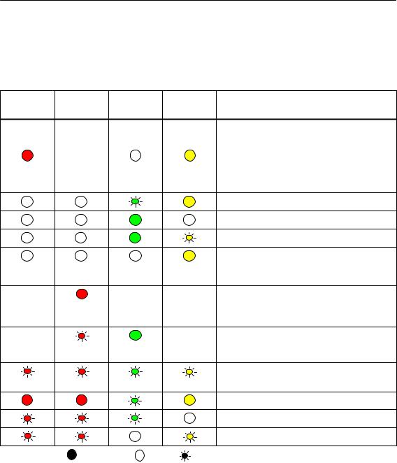
The different combinations of the LEDs on the front panel indicate the status:
|
SF(red) |
BF (red) |
RUN |
STOP |
CP Operating Mode |
|
|
(green) |
(yellow) |
||||
|
S Starting up after power “ON” |
|||||
|
or |
|||||
|
− |
S Stopped (STOP) with errors |
||||
|
In this state, the CPU or intelligent |
|||||
|
modules in the rack remain accessible |
|||||
|
using PG functions. |
|||||
|
Starting up (STOP->RUN) |
|||||
|
Running (RUN) |
|||||
|
Stopping (RUN->STOP) |
|||||
|
Stopped (STOP) |
|||||
|
In the STOP mode configuring and performing |
|||||
|
diagnostics on the CP remain possible. |
|||||
|
− |
− |
− |
S No LAN cable plugged in |
||
|
or |
|||||
|
S Duplicate IP address detected |
|||||
|
− |
− |
− |
The CP is configured as a PROFINET IO |
||
|
device; there is no data exchange with the |
|||||
|
PROFINET IO controller |
|||||
|
Module fault / system error |
|||||
|
Downloading firmware. |
|||||
|
Firmware was successfully downloaded. |
|||||
|
Firmware could not be downloaded. |
|||||
|
Legend: |
(colored) on |
off |
(colored) flashing |
“−” any |
|
CP 343-1 Lean for Industrial Ethernet / Manual Part B3L |
B3L−15 |
|
Release 03/2007 |
C79000-G8976-C198-04

4 Displays
LEDs for displaying the CP communication status
In addition to the LEDs that signal the CP state, the following LEDs provide information about the status of the CP interface to Industrial Ethernet.
Table 4-1
|
LED |
Display |
Meaning |
||||
|
RX/TX (green) |
The CP is sending/receiving over Industrial |
|||||
|
Ethernet |
||||||
|
Note: |
||||||
|
Sending / receiving over PROFINET IO is |
||||||
|
not signaled here. |
||||||
|
P1 / P2 |
Port has no connection to |
|||||
|
(green / yellow) |
Industrial Ethernet. |
|||||
|
green |
Existing connection over port to |
|||||
|
Industrial Ethernet (LINK status). |
||||||
|
green / |
LED flashes yellow (constant light green): |
|||||
|
yellow |
Port sending/receiving over |
|||||
|
Industrial Ethernet or PROFINET IO. |
||||||
|
Note: |
||||||
|
All received / sent frames are signaled for |
||||||
|
each specific port including those simply |
||||||
|
forwarded by the switch. |
||||||
|
P1 / P2 |
yellow |
Continuous data transfer at the port over |
||||
|
(green / yellow) |
Industrial Ethernet (for example |
|||||
|
PROFINET IO). |
||||||
|
Legend: |
(colored) on |
off |
(colored) flashing |
“−” any |
|
B3L−16 |
CP 343-1 Lean for Industrial Ethernet / Manual Part B3L |
|
Release 03/2007 |
C79000-G8976-C198-04

5 Performance Data
5 Performance Data
5.1Number of Possible Connections over Ethernet
Table 5-1
|
Characteristic |
Explanation / Values |
|
Permitted number of simultaneous connections in |
12 maximum |
|
total over Industrial Ethernet |
|
Example of Maximum Load
You can operate:
4 S7 connections
4 ISO-on-TCP connections
2 TCP connections
2 UDP connections Also:
SFurther TCP connections for Web diagnostics
S1 PROFINET connection to a PROFINET IO controller
5.2Characteristic Data for S7 Communication
Table 5-2
|
Characteristic |
Explanation / Values |
||
|
Number of connections for S7 communication on |
4 maximum |
||
|
Industrial Ethernet for |
(the number depends on the CPU type being used. |
||
|
S Operator control and monitoring functions (HMI) |
Please refer to /1/ for the values for your CPU.) |
||
|
S S7 connections configured at one end |
|||
|
LAN interface − data record length per protocol unit |
|||
|
S |
sending |
240 bytes / PDU |
|
|
S |
receiving |
||
|
240 bytes / PDU |
|||
|
CP 343-1 Lean for Industrial Ethernet / Manual Part B3L |
B3L−17 |
|
Release 03/2007 |
C79000-G8976-C198-04
 Loading…