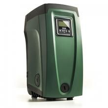
Насосные станции повышения давления DAB E.sybox Mini 3 предназначены для использования на объектах, с максимальным расходом воды не превышающим 4,8 м3/ч. Это могут быть как частные дома, так и предприятия малого бизнеса (автомойки, кафе, бары и т.д.) испытывающие неудобства из-за низкого или неравномерного напора воды. Мини насосная станция не просто повышает давление, а поддерживает его на заданном уровне, вне зависимости от количества одновременно открытых кранов или используемых устройств: посудомоечных и стиральных машин, гидробоксов, сантехнических приборов.
В комплект оборудования входят все необходимые устройства: насос с частотным регулированием, клапана, блок управления, литровая буферная емкость высокого давления, датчики. Автоматика определяет текущие параметры локальной распределительной сети и соответственно повышает или снижает скорость вращения электродвигателя. При резком увеличении расхода вызванного повреждением трубопровода или запорной арматуры, эта бытовая насосная станция самостоятельно прекращает подачу воды, предотвращая затопление помещений.
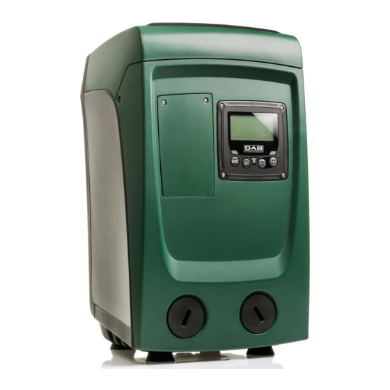
Важным достоинством оборудования является низкий уровень звукового давления, создаваемого при работе. Это практически бесшумная станция водоснабжения, которую можно разместить в любом удобном месте. Монтаж установки допускается производить как в горизонтальном, так и вертикальном положении.
E.sybox мини является идеальным продуктом для решения любых проблем с давлением воды в домашних условиях. Она состоит из самовсасывающего насоса. частотного преобразователя. датчика давления и протока. а также ЖК-дисплея и встроенного расширительного бака объемом 1 л.
ПРЕИМУЩЕСТВА
+ КОМФОРТ:
Постоянное давление воды
Низкий уровень шума
Отсутствие вибрации
+ Универсальность:
Очень компактные размеры
Может быть установлен горизонтально, вертикально или на стене
+ Простота:
Легкое и быстрое подключение
Простая настройка (большой ЖК-дисплей)
Простота обслуживания
+ Энергоэффективный
Встроенный частотный преобразователь (инвертор)
АКСЕССУАРЫ:
E.sybox мини может быть объединен с E.sywall (60161442). кронштейном для настенного монтажа. что позволяет экономить пространство. E.sywall (60161442) подходит. как для E.sybox. так и для E.sybox мини.
- Manuals
- Brands
- DAB Manuals
- Water Pump
- e.sybox mini3
- Instruction for installation and maintenance
-
Bookmarks
Quick Links
INSTRUCTIONS FOR INSTALLATION AND MAINTENANCE
INSTRUCTIONS POUR L’INSTALLATION ET L’ENTRETIEN PARA
LA INSTALACIÓN Y EL MANTENIMIENTO
Related Manuals for DAB e.sybox mini3
Summary of Contents for DAB e.sybox mini3
-
Page 1
INSTRUCTIONS FOR INSTALLATION AND MAINTENANCE INSTRUCTIONS POUR L’INSTALLATION ET L’ENTRETIEN PARA LA INSTALACIÓN Y EL MANTENIMIENTO… -
Page 3
ّ… -
Page 4
ENGLISH INDEX Monitor Menu Warnings Responsibility 1. General Setpoint Menu Manual Menu 2. Installation Installer Menu User Menu Status RS: Rotation speed display VP: Pressure display “BL” “… -
Page 5
ENGLISH “ Wall installation Non-return valve 11. Disposal 12. Guarantee… -
Page 7
ENGLISH SITUATION OF GENERAL DANGER. SITUATION OF ELECTRIC SHOCK HAZARD. Failure to re- Safety WARNINGS Skilled personnel… -
Page 8
ENGLISH 1- GENERAL Applications… -
Page 9
ENGLISH • • 1.2 Integrated Expansion Vessel • • •… -
Page 10
ENGLISH 11 1 7 ELECTRIC POWER SUPPLY 17.5×10.3×9.5 inches STRUCTURAL 30 lbs ( CHARACTERI- STICS 180 ft ( 22 gpm (80L/min) HYDRAULIC 26ft ( PERFORMANCE pressure 110psi ( 104°F (40 WORKING 122°F ( CONDITIONS 14-140°F (… -
Page 11
ENGLISH Constant pressure • • FUNCTIONALITY PROTECTIONS 2- INSTALLATION •… -
Page 12
ENGLISH 0.4″ ( • 0 . 4 » ( • 7.9″ ( • 1″ ( < 1″ (25 > 1″ (25 2.1.2.Loading Operation… -
Page 13
ENGLISH 0 . 4 » ( • 7.9″ ( • 2.2 -… -
Page 14
ENGLISH 2.2.3 Loading Operation • • • • • • 0.2 Gal ( . -
Page 15
ENGLISH Unipolar pulsed Table 0 3 — COMMISSIONING 26ft (… -
Page 16
ENGLISH Pstart = SP – RP Type A Type B Neutral Blue Blue Green Table 0 bis Table 0 tris tory are: • • •… -
Page 17
ENGLISH Operation… -
Page 18
ENGLISH Monitor Warning leds Setpoint • • Manual Menus Installer Access to the menus values Reset MENU NAME HOLD-DOWN TIME User… -
Page 19
ENGLISH Reduced menu (visible) Extended menu (direct access or password) Manual Menu User Menu Monitor Menu Setpoint Menu Installer Menu Main Menu STATO STATUS MAIN for restart Contrast Setpoint pressure Pressure Pressure Type of plant… -
Page 20
ENGLISH HW e SW Reset faults and… -
Page 21
ENGLISH Status Pressure… -
Page 22
ENGLISH Identifying Motor stopped Motor stopped Identifying Plant pressure FAULT Motor stopped… -
Page 23
ENGLISH 5 — MEANING OF THE INDIVIDUAL PARAMETERS 5.1 — User Menu 5.1.11 5.1.12… -
Page 24
ENGLISH 5.1.13 5.1.14 5.1.15 • Italian • • • • • • • • Slovak • • Russian 5.3 — Setpoint Menu 5.2 — Monitor Menu… -
Page 25
ENGLISH For example: SP = 3,0 [bar]; RP = 0,3 [bar]; During normal operation the system is pressurised at 3.0 [bar]. The electropump restarts when the pressure falls belowai 2,7 [bar]. 5.4 — Manual Menu Starting the pump… -
Page 26
ENGLISH 5.4.10 5.5 — Installer Menu Quantity Pressure… -
Page 27
ENGLISH Value 5.6 -… -
Page 28
ENGLISH • •… -
Page 29
ENGLISH 6.1.1 -… -
Page 30
ENGLISH… -
Page 31
ENGLISH Display overload Value Identifying Type of plant… -
Page 32
ENGLISH 8 — PARTICULAR INSTALLATIONS… -
Page 33
ENGLISH 8.2 — Wall installation 9. MAINTENANCE… -
Page 34
ENGLISH 9.3 — Non-return valve… -
Page 35
ENGLISH… -
Page 36
ENGLISH 9.5 — Expansion Vessel Fault Red: off does not Blue: off Red: on does not Blue: off Red: off does not Blue: off Red: off does not Blue: off 10 — TROUBLESHOOTING… -
Page 37
ENGLISH Red: on Setpoint not Blue: off set RM value Red: off delivery Blue: off Red: on Faulty pressure Blue: off Red: off Red: on out utility Faulty non-return Faulty pressure Blue: off Blue: off pressure Red: off Red: on Blue: off Blue: off utility is not… -
Page 38
ENGLISH 11 — DISPOSAL 12 — GUARANTEE… -
Page 39
FRANÇAIS SOMMAIRE Légende Responsabilité 1. Généralités Menu Manuel 2. Installation Menu installateur Menu utilisateur État… -
Page 40
FRANÇAIS “ “ “ “SC” 9. Entretien 11. Mise au rebut 12. Garantie… -
Page 41
FRANÇAIS… -
Page 42
FRANÇAIS LÉGENDE SITUATION DE DANGER GÉNÉRAL. SITUATION DE DANGER D’ÉLECTROCUTION. Le non-res- AVERTISSEMENTS… -
Page 43
FRANÇAIS RESPONSABILITÉ’ 1- GÉNÉRALITÉS Applications… -
Page 44
FRANÇAIS • • 1.2 Vase d’expansion intégré • • •… -
Page 45
FRANÇAIS 11 127 Tension* ALIMENTATION Courant de fuite vers la terre d’appui CARACTÉ- CONSTRUCTIVES Classe d’isolation du… -
Page 46
FRANÇAIS PRESTATIONS CONDITIONS D’EXERCICE • • FONCTIONNALITÉS ET PROTECTIONS • 2- INSTALLATION… -
Page 47
FRANÇAIS 00 mm N P T < 25 > 25 • • •… -
Page 48
FRANÇAIS 2.2 — Installations sur niveau et sous niveau… -
Page 49
FRANÇAIS • • • • • • • •… -
Page 50
FRANÇAIS litres 3 — MISE EN ROUTE Installation sur niveau et sous niveau… -
Page 51
FRANÇAIS Connexion Typologie A Typologie B Marron Marron Neutre Vert Unipolaire Alternatif Continu pulsant Tableau 0 bis Convertisseur Tableau 0 Tableau 0 tris • • •… -
Page 52
FRANÇAIS Pstart = SP – RP ration par défaut Fonctionnement dire:… -
Page 53
FRANÇAIS 4 — LE CLAVIER DE L’ÉCRAN DEL de signalisation • • Menu Accès aux menus… -
Page 54
FRANÇAIS valeurs route de l’appareil teur NOM DU TOUCHES D’ACCÈS DIRECT TEMPS DE PRESSION MENU Utilisateur Point de pa- Manuel Installateur… -
Page 55
FRANÇAIS Menu réduit (visible) Menu étendu (accès direct ou mot de passe) Menu Utilisateur Menu Monitor Menu Setpoint Menu Manuel Menu Installateur STATUT STATUT PRINCIPAL Pression Contraste Pression Pression Type d’installation Courant de Courant de Gain Gain dissipateur Heures de travail dissipateur aspiration en aspiration… -
Page 56
FRANÇAIS HW et SW passe… -
Page 57
FRANÇAIS État:… -
Page 58
FRANÇAIS Pression: Pression de l’installation FAULT sauf RF et PW… -
Page 59
FRANÇAIS 5 — SIGNIFICATION DES DIFFÉRENTS PARAMÈTRES 5.1 — Menu Utilisateur… -
Page 60
FRANÇAIS 5.1.13 — Débit • Italien • • • • • Hollandais • Suédois • • • • Russe 5.2 -… -
Page 61
FRANÇAIS Exemple : SP = 3,0 [bar] ; RP = 0,3 [bar]; Durant le fonctionnement normal, l’installation est pressurisée à 3,0 [bar]. Le redémarrage de l’électropompe a lieu quand la pression descend sous 2,7 [bar]. 5.4 — Menu Manuel Démarrage de la pompe… -
Page 62
FRANÇAIS 5.5 — Menu Installateur appuyer sur SET Valeur Internationale Anglo-saxon Pression… -
Page 63
FRANÇAIS Valeur 5.6 — sur SET… -
Page 64
FRANÇAIS • L’opé- •… -
Page 65
FRANÇAIS l’arrivée aspiration… -
Page 66
FRANÇAIS… -
Page 67
FRANÇAIS 7 — REMISE À ZÉRO ET PARAMÉTRAGES DU CONSTRUCTEUR d’eau Valeur Rappel Installation… -
Page 68
FRANÇAIS 8 — INSTALLATIONS SPÉCIALES Type d’installation aspiration proportionnel étapes suivantes:… -
Page 69
FRANÇAIS 9. ENTRETIEN… -
Page 70
FRANÇAIS 9.3 — Clapet de non-retour… -
Page 71
FRANÇAIS… -
Page 72
FRANÇAIS 9.5 — Vase d’expansion 10 — RÉSOLUTION DES PROBLÈMES Bleu : éteint Bleu : éteint supérieur par rapport Bleu : éteint Fuite de l’instal- Pénétration d’air Bleu : éteint… -
Page 73
FRANÇAIS Le point de para- Profondeur Bleu : éteint d’aspiration Conduit d’aspi- Bleu : éteint Capteur de pres- Rotor ou partie Bleu : éteint Bleu : éteint Fuite de l’instal- utilisateur Clapet de non-re- Bleu : éteint ne le Bleu : éteint La pression de l’eau n’est pas… -
Page 74
FRANÇAIS 11 — MISE AU REBUT 12 — GARANTIE •… -
Page 75
ESPAÑOL ÍNDICE Leyenda Responsabilidad 1. Generalidades… -
Page 76
ESPAÑOL “ “PB” “SC” 12. Garantía… -
Page 78
ESPAÑOL SITUACIÓN DE PELIGRO GENERAL. SITUACIÓN DE PELIGRO DE DESCAR-GA ELÉCTRICA. El ADVERTENCIAS… -
Page 79
ESPAÑOL RESPONSABILIDAD GENERALIDADES Aplicaciones Cara Cara… -
Page 80
ESPAÑOL Cara • • • • •… -
Page 81
ESPAÑOL Donde: ALIMENTACIÓN ELÉCTRICA de apoyo CARACTERÍSTICAS DE CONSTRUCIÓN PRESTACIONES HIDRÁULICAS… -
Page 82
ESPAÑOL CONDICIONES DE FUNCIONAMIENTO • • FUNCIONES Y PROTECCIONES • 2- INSTALACIÓN 2.1 — rios… -
Page 83
ESPAÑOL 2.1.1 < 1″ (25 > 1″ (25 • • •… -
Page 84
ESPAÑOL 2.2 — 2.1.2. • litros •… -
Page 85
ESPAÑOL 2.2.1 2.2.2 • • • • • •… -
Page 86
ESPAÑOL litros 2.2.3 3 — PUESTA EN FUNCIONAMIENTO 3.1 -… -
Page 87
ESPAÑOL Tipología A Tipología B Fase Neutro Celeste Celeste Verde Unipolar Alterna Continua nentes de alta Inversor de • • •… -
Page 88
ESPAÑOL Pstart = SP – RP 3.3 — Cebado Funcionamiento… -
Page 89
ESPAÑOL Led de señalización • • Menú Acceso a los menús… -
Page 90
ESPAÑOL 4.1 A NOMBRE BOTONES DE ACCESO DIRECTO TIEMPO DE PRESIÓN DEL MENÚ Usuario Monitor Setpoint Manual Instalador los valores… -
Page 91
ESPAÑOL Menú reducido ( visible ) Menú ampliado ( acceso directo o contraseña ) PRINCIPAL Menú Usuario Menú Monitor Menú Setpoint Menú Manual Menú Instalador ESTADO Contraste ESTADO Corriente de fase Corriente de fase disipador disipador… -
Page 92
ESPAÑOL HW y SW Leyenda… -
Page 93
ESPAÑOL 4.2 — entra pulsando MODE 4.3 — de la pantalla Estado:… -
Page 94
ESPAÑOL Motor detenido FALLO Motor detenido 4.4 — 4.5 -… -
Page 95
ESPAÑOL 5 — SIGNIFICADO DE CADA PARÁMETRO 5.1 — Menú Usuario 5.1.11 — 5.1.1 — Estado… -
Page 96
ESPAÑOL 5.1.13 — Contraste de la pantalla • Italiano • • • • • Holandés • • • • • Ruso 5.3 — Menú Setpoint 5.2 — Menú Monitor… -
Page 97
ESPAÑOL Puesta en marcha de la bomba SP y a Ejemplo: SP = 3,0 [bar]; RP = 0,3 [bar]; Durante el funcionamiento normal, la instalación está presurizada en 3,0 [bar]. La electrobomba podrá reencenderse cuando la presión desciende por debajo de 2,7 [bar]. 5.4.1 — Estado 5.4 — Menú… -
Page 98
ESPAÑOL IMPORTANTE 5.5 — Menú Instalador Magnitud Caudal… -
Page 99
ESPAÑOL valor Retardo de apagado 5.6 — IMPORTANTE… -
Page 100
ESPAÑOL • •… -
Page 101
ESPAÑOL 6 — SISTEMAS DE PROTECCIÓN pantalla 6.1 — 6.1.1 — “BL” pantalla… -
Page 102
ESPAÑOL 6.1.2 — 6.1.6 — “PB” 6.1.7 — “SC” 6.1.3 — 6.2 — 6.3 -… -
Page 103
ESPAÑOL 7.1 — por el usuario 7.2 — la pantalla 7.3 — Valor… -
Page 104
ESPAÑOL 8 — INSTALACIONES ESPECIALES 8.1 -… -
Page 105
ESPAÑOL 8.2 — en su asiento 9. MANTENIMIENTO 9.1 -… -
Page 106
ESPAÑOL 9.3 — 9.2 — litros si no se… -
Page 107
ESPAÑOL 9.4 -… -
Page 108
ESPAÑOL 9.5 — 10 — SOLUCIÓN DE LOS PROBLEMAS rotura un nivel superior Pérdida en la Rodete o parte Entrada de aire averiado… -
Page 109
ESPAÑOL pantalla Setpoint no profundidad de el valor RM pantalla averiado Rodete o parte La pantalla dido Pérdida en la pantalla Válvula antirretorno pantalla no es en el vaso de… -
Page 110
ESPAÑOL 11 — DESGUACE 12 — GARANTÍA •… -
Page 111
Tel: +27 12 361 3997 Fax: +7 495 122 00 36 Fax: +49 2151 82136-36 :1-843-797-3366 Fax: +27 12 361 3137 DAB PUMPS POLAND SP. z.o.o. DAB UKRAINE DAB PUMPS CHINA Mokotow Marynarska No.40 Kaituo Road, Qingdao Economic & H-8800…
RU
РУССКИЙ
Кнопки + и – позволяют увеличивать и уменьшать давление нагнета-
ния установки.
Для выхода из текущего меню и возврата к главному меню нужно на-
жать на SET. Диапазон регуляции: 1-5.5 бар (14-80 psi).
5.3.1 — SP: Настройка давления уставки
Давление герметизации системы.
Давление повторного пуска насоса связано, помимо задан-
ного давления SP также с RP.
RP выражает снижение давления, относительно «SP», что
приводит к запуску насоса.
Пример: SP = 3,0 [бар]; RP = 0,3 [бар];
Во время нормальной работы установка имеет давление 3,0 [бар].
Повторный пуск электронасоса происходит, когда давление снижа-
ется ниже 2,7 [бар].
Слишком высокая настройка давления (SP) по сравнению с
характеристиками насоса может привести к возникновению
ложной тревоги отсутствия воды BL; в этих случаях нужно
снизить заданное давление.
5.4 — Меню Ручной режим
В ручном режиме сумма давления на входе и максимального
подаваемого давления не должна превышать 6 бар.
В главном меню следует держать одновременно нажатыми кнопки
«SET» и «+» и «-» до появления страницы ручного меню (или использо-
вать меню выбора, нажав на + или — ).
Для выхода из текущего меню и возврата к главному меню нужно на-
жать на SET. Вход в ручной режим при нажатии кнопок SET + — приво-
дит машину в состояние форсированного ОСТАНОВА. Эта функция
может использоваться для остановки машины.
Внутри ручного режима, независимо от показываемого параметра,
всегда возможно выполнить следующие команды:
Временный запуск электронасоса.
Одновременное нажатие кнопок MODE и -+ приводит к запуску насоса
на скорости RI и состояние движения сохраняется до тех пор, пока
две кнопки остаются нажатыми.
207
Когда управление насоса ON или насоса OFF включено, появляется
сообщение на дисплее.
Запуск насоса
Одновременное нажатие кнопок MODE — + в течение 2 S приводит к
запуску насоса на скорости RI. Состояние движения сохраняется до
тех пор, пока не нажимают на кнопку SET. Последующее нажатие на
кнопку SET приводит к выходу из меню ручного режима.
Когда управление насоса ON или насоса OFF включено, появляется
сообщение на дисплее.
В случае работы в данном режиме более 5 минут без гидравлического
расхода машина подает сигнал тревоги из-за перегрева, показывая
ошибку PH. После появления ошибки PH, восстановление происходит
только автоматически. Время восстановления составляет 15 минут;
если ошибка PH появляется более 6 раз подряд, время восстановле-
ния увеличивается до 1 ч. После восстановления после этой ошибки
насос останавливается до тех пор, пока пользователь не запустит его
вновь при помощи кнопок «MODE» «-» «+ .
5.4.1 — Состояние:
Показывает состояние насоса.
5.4.2 — RI: Настройка скорости
Задает скорость двигателя в оборотах в минуту. Позволяет форсиро-
вать число оборотов на заданное значение.
5.4.3 — VP: Визуализация давления
Давление установки, измеренное в [бар] или [пси], в зависимости от
заданной единицы измерений.
5.4.4 — VF: Визуализация расхода
Показывается расход в выбранной единице измерения. Единица-
ми измерения могут быть [л/мин] или [галлон/мин], см. пар. 5.5.3 —
MS: Система измерения.
5.4.5 — PO: Визуализация потребляемой мощности
Потребляемая мощность электронасоса в [кВт].
В случае превышения максимальной допустимой мощности мигает
соответствующий РО.
- Page 1
INSTRUCTIONS FOR INSTALLATION AND MAINTENANCE INSTRUCTIONS POUR L’INSTALLATION ET L’ENTRETIEN… - Page 2
Manual valid for firmware versions 2.x.y-4.x-1.x Manuel valide pour les versions micrologiciel 2.x.y-4.x-1.x… -
Page 3: Table Of Contents
ENGLISH INDEX 5.1.14 VE: Version display 5.1.15 FF: Fault log display 5.2 Monitor Menu Warnings 5.2.1 CT: Display contrast Responsibility 5.2.2 BK: Display brightness 5.2.3 TK: Backlight switch-on time 1. General 5.2.4 LA: Language 1.1 Description of the Integrated Inverter 5.2.5 TE: Dissipator temperature display 1.2 Integrated expansion vessel 5.3 Setpoint Menu…
- Page 4
ENGLISH 6.1.2 “Anti-Cycling (Protection against continuous cycles without utility request) 6.1.3 “Anti-Freeze (Protection against freezing of water in the system) 6.1.4 “BP1” Blockage due to fault of the delivery pressure sensor 6.1.5 “BP2” Blockage due to fault of the suction pressure sensor 6.1.6 “PB”… -
Page 6: Key
ENGLISH It is the responsibility of the installer to make sure that the power supply system is equipped with an efficient grounding system The following symbols have been used in the discussioni: according to the regulations in force. SITUATION OF GENERAL DANGER. Failure to respect the To improve immunity to possible noise radiating to other equip- instructions that follow may cause harm to persons and ment, it is advisable to use separate wiring to power the inverter.
-
Page 7: Responsibility
ENGLISH RESPONSIBILITY Face A: a door allows access to the Technical Compartment. The Manufacturer does not vouch for correct operation of the electropumps or answer for any damage that they may cause if they have been tampered with, modified and/or run outside the recommended work range or in contrast with other indications given in this manual.
-
Page 8: Description Of The Integrated Inverter
ENGLISH Face F: as indicated by the label to be removed, the 1” cap next to the The Inverter control ensures different functions, the most important of word “IN” on face C has a dual function: in the case of horizontal installa- which, for pumping systems, are the maintaining of a constant pressure tion, the outlet that is closed by the cap acts as the system’s loading door value in delivery and energy saving.
-
Page 9: Technical Characteristics
ENGLISH The expansion vessel is preloaded with pressurised air through the valve 1.3 Technical characteristics accessible from the special maintenance compartment (Fig.1, Face F). ³ The preload value with which the expansion vessel is supplied by the man- Topic Parameter e.sybox mini ufacturer is in agreement with the parameters SP and RP set as default, Voltage*…
-
Page 10: Installation
ENGLISH • The electrical connection is made in a dry place, far from any Constant pressure possible flooding. Protection against dry running • The earth system must comply with the regulations. If you are not sure of the absence of foreign bodies in the water to be Antifreeze protection pumped, install a filter on the system intake that is suitable for catching FUNCTIONALITY AND…
-
Page 11: Hydraulic Connections
ENGLISH • The distance of at least 10mm between Face E of the system and any The brass threads are housed in technopolymer seats. When wall is obligatory to ensure ventilation through the grids provided • I f making the connection watertight by adding material (e.g. Teflon, you expect to have to drain the system from its discharge door and hemp,…) ensure that the gasket is not too thick: under the action not from the system, leave a further distance sufficient to manoeuvre…
-
Page 12: Horizontal Configuration
ENGLISH 2.1.1) has been placed close to the system entry door, the quantity of • The distance of at least 10mm between Face B of the system and water with which to fill the system should be 0,9 litres. It is recommended an obstruction is obligatory to let out the power supply cable to the to fit the non-return valve at the end of the suction pipe (foot valve) so as mains socket.
-
Page 13: Loading Operation Installation Above Head And Below Head
ENGLISH Figure 10 2.2.3 Loading Operation Installation above head and below head Figure 9 With reference to its position with respect to the water to be pumped, the instal- lation of the system may be defined “above head” or “below head”. In particular the installation is defined “above head”…
-
Page 14: Commissioning
ENGLISH as to be able to fill it quickly too during the loading operation. In this case the Type of possible fault currents to earth quantity of water necessary for the loading operation will depend on the length of the suction pipe (0,7 litres + …). With high- Unipolar Installation “below head”: if there are no check valves between the water de-…
-
Page 15: Configuration Of The Integrated Inverter
ENGLISH For pumps not supplied with a plug, the correspondence of the colours of Pstart = SP – RP For example: 2.7 – 0.3 = 2.4 bar in the default the leads is as indicated in table 0bis: configuration The system does not work if the utility is at a height higher than the equiva- Connection Type A Type B…
-
Page 16: The Keypad And The Display
ENGLISH in depth in a time of less than 5 minutes. As soon as the product detects The user interface is composed of a keypad with 128×240 pixel LCD dis- a regular flow in delivery, it leaves the priming procedure and starts its play and with POWER, COMM, ALARM warning leds as can be seen in regular work.
-
Page 17: Direct Access With A Combination Of Keys
ENGLISH When the + key or the — key is pressed the selected value is modified and saved immediately in the permanent memory (EE- MENU NAME DIRECT ACCESS KEYS HOLD-DOWN TIME prom). If the machine is switched off, even accidentally, in this phase it does not cause the loss of the parameter that has just been set.
- Page 18
ENGLISH Reduced menu (visible) Extended menu (direct access or password) Manual Menu User Menu Monitor Menu Setpoint Menu Installer Menu Tech. Assist. Menu Main Menu set-minus-plus mode set-minus mode-set mode-set-minus mode-set-plus MAIN STATUS STATUS (Main Page) Contrast Setpoint pressure Decrease pressure Block time for Revs per minute Speed setting… - Page 19
ENGLISH Reset faults and Power histogram warnings Output flow meter Modify Password Information HW e SW Fault & Warning (Log) Table 3: Menu structure Parameters available in version K. Parameters available only in version DV… -
Page 20: Access By Name With A Drop-Down Menu
ENGLISH 4.2 — Access by name with a drop-down menu The selection of the various menus is accessed by name. From the main menu you access menu selection by pressing either of the + or – keys. The names of the menus that can be accessed appear on the menu selec- tion page and one of the menus is highlighted by a bar (see Figure 13-14).
-
Page 21: Blocking Parameter Setting By Password
ENGLISH If the case occurs the following may appear: Fault indications Indications on the status bar at the bottom of each page Warning indications Identifying Specific icons Description code The error conditions are indicated in Table 8. The other displays are indi- Motor stopped cated in Table 4.
-
Page 22: Meaning Of The Individual Parameters
ENGLISH 5.1.6 — C1: Phase current display 5 — MEANING OF THE INDIVIDUAL PARAMETERS Motor phase current in [A]. The inverter makes the system work at constant pressure. This If the maximum allowed current is exceeded, the identification C1 blinks, regulation is appreciated if the hydraulic plant downstream from indicating an imminent tripping of the overload protection.
-
Page 23: Output Flow Meter
ENGLISH In this menu, by pressing the MODE key, the following values are dis- 5.1.13 — Output flow meter played in sequence. The page shows two flow meters. The first shows the total output flow delivered by the machine. The second shows a partial count and can be 5.2.1 — CT: Display contrast reset by the user.
-
Page 24: Sp: Setting The Setpoint Pressure
ENGLISH 5.3.1 — SP: Setting the setpoint pressure Starting the pump Pressure at which the system is pressurised. Holding down the MODE — + keys simultaneously for 2 sec. causes the pump to start at speed RI. The running status remains until the SET key The pump restarting pressure is linked not only to the set pressure is pressed.
-
Page 25: Sv: Tupply Voltage
ENGLISH 5.4.8 — SV: Supply voltage tems. In the presence of swings in pressure that cannot be stabilised by Present only in some models. adjusting the parameters GI and GP, change to mode 2. 5.4.9 — SR: Supply range Present only in some models. IMPORTANT: The regulating parameters GP and GI also change in the Indicates the range of supply voltage found.
-
Page 26: As: Association Of Devices
ENGLISH associated is detected (irrespective of the result of association); if not de- 5.5.4 — AS: Association of devices vice can be seen within the space of 1 minutes, the machine automatically Allows connection/disconnection with the following devices: leaves association status. You can leave the search status for wireless •…
-
Page 27: Technical Assistance Menu
ENGLISH 5.6 — Technical Assistance Menu from those set by the factory. For nearly all plants the factory-set GP and Present only in models with Kiwa function. GI parameters are optimal. However, should any problems occur in adjust- Advanced settings to be made only by skilled personnel or under the direct ment, these settings may be varied.
-
Page 28: Rf: Fault And Warning Reset
ENGLISH Tripping of this function causes the pump to cut out; it may be reset auto- • Make a note of the values of all the parameters, reset the device with matically or manually. The automatic reset requires that, to leave the error the factory values, see paragraph 7.3.
-
Page 29: Description Of Blockages
ENGLISH pump, the automatic restart will try to restart the pump. Blockage conditions If the parameter SP is not correctly set, the protection against Display indication Description water lack may not work correctly. Cutout due to pump overheating 6.1.2 — Anti-Cycling (Protection against continuous cycles without Blockage due to water lack utility request) If there are leaks in the delivery section of the plant, the system starts and…
-
Page 30: Bp1″ Blockage Due To Fault Of The Delivery Pressure Sensor
ENGLISH 6.1.4 — “BP1” Blockage due to fault of the delivery pressure sensor matically starts a test procedure to check whether the machine is really (system pressurisation) left definitively and permanently dry. If during the sequence of operations If the device detects a fault in the delivery pressure sensor the pump re- an attempted reset is successful (for example, the water comes back), the mains blocked and the error signal “BP1”…
-
Page 31: Reset And Factory Settings
ENGLISH 7 — RESET AND FACTORY SETTINGS Language 7.1 — General system reset Setpoint pressure [bar] To reset the system, hold down the 4 keys simultaneously for 2 sec. This Revs per minute in manual 3200 operation is the same as disconnecting the power, waiting for it to close mode [rpm] down completely and supplying power again.
-
Page 32: Particular Installations
ENGLISH 8 — PARTICULAR INSTALLATIONS 7. fill the pump, connect the power supply, start the system. 8.1 — Inhibiting self-priming The product is made and supplied with the capacity of being self-priming. With reference to par. 4, the system is able to prime and therefore oper- ate in whatever installation configuration chosen: below head or above head.
-
Page 33: Wall Installation
With the product, DAB supplies a metal key with a hexagonal section delivery (if not used).
-
Page 34: Non-Return Valve
ENGLISH Though essentially drained, the system is unable to expel all the water that it contains. During handling of the system after emptying it, some small amounts of water may probably leak out from the system. 9.3 — Non-return valve The system has an integrated non-return valve which is necessary for cor- rect operation.
-
Page 35: Expansion Vessel
ENGLISH in starting the pump: after a period of inactivity, perhaps with the system 9.5 — Expansion Vessel drained, the salts dissolved in the water could have settled and formed See paragraph 1.2 for the operations to check and adjust the air pressure calcification between the moving part (motor shaft) and the fixed part of in the expansion vessel and to replace it if it is broken.
- Page 36
ENGLISH Solving typical problemsi 1. As the suction depth increases the hydraulic performance of the product decreases. Check whether the suction depth can Fault Probable Causes Remedies 1. Suction depth too be reduced. Use a suction pipe high. with a larger diameter (but never Red: off 2. -
Page 37: Updating The Firmware
ENGLISH 11 — UPDATING THE FIRMWARE The firmware can be updated with the D-Connect Box via wireless com- 1. No water. 1-2. Prime the pump and check 2. Pump not primed. whether there is air in the pipe. munication. To perform the update, refer to the D-Connect Box manual. The display Red: on 3.
- Page 38
FRANÇAIS SOMMAIRE 5.1.14 VE: Affichage de la version 5.1.15 FF: Affichage pannes et avertissements (historique) Légende 5.2 Menu Écran Avertissements 5.2.1 CT : Contraste écran Responsabilité 5.2.2 BK : Luminosité écran 5.2.3 TK : Temps d’allumage éclairage de fond 1. Généralités 5.2.4 LA : Langue 1.1 Description de l’inverseur intégré… - Page 39
FRANÇAIS 6.1.1 “BL » Anti Dry-Run (protection contre le fonctionnement à sec) 6.1.2 Anti-Cycling (protection contre les cycles continus sans demande de l’utilisateur) 100 6.1.3 “Anti-Freeze (protection contre le gel de l’eau dans le système) 6.1.4 “BP1” Blocage pour panne du capteur de pression à l’arrivée 6.1.5 “BP2”… - Page 40
FRANÇAIS… -
Page 41: Légende
FRANÇAIS LÉGENDE L’installateur a la responsabilité de s’assurer que le système d’a- limentation est équipé d’un système de mise à la terre efficace, Les symboles suivants sont employés dans le présent document: conformément aux réglementations en vigueur. SITUATION DE DANGER GÉNÉRAL. Le non-respect des Afin d’améliorer l’immunité…
-
Page 42: Responsabilité
FRANÇAIS RESPONSABILITÉ’ Pan A: porte d’accès au logement technique. Le constructeur ne répond pas du bon fonctionnement des électropompes ou des dommages éventuels que celles-ci peuvent provoquer si celles-ci sont manipulées, modifiées et/ou si elles fonctionnement en-hors du lieu de travail conseillé…
-
Page 43: Description De L’inverseur Intégré
FRANÇAIS Pan F: comme indiqué sur l’étiquette à retirer, le bouchon de 1” en corres- Le contrôler par le biais de l’inverseur assure différentes fonctionnalités, pondance de la mention « IN » sur le pan C a deux fonctions: pour l’instal- dont les plus importantes sont, pour les systèmes de pompage, le maintien lation horizontale, la bouche qui est fermée par le bouchon est la porte de d’une valeur de pression constante en distribution et l’économie d’énergie.
-
Page 44: Caractéristiques Techniques
FRANÇAIS que la quantité d’eau fournie dépendra également des paramètres SP et L’éventuelle opération de contrôle et/ou de rétablissement de la RP réglables sur le système (parag. 4-5). pression de l’air doit être effectuée à circuit de distribution non Le vase d’expansion est pré-chargé à l’air sous pression à travers la vanne pressurisé…
-
Page 45: Installation
FRANÇAIS Prévalence maximum 55 m Le système ne peut pas être utilisé pour pomper de l’eau salée, Portée maximum 80 l/min du lisier, des liquides inflammables, corrosifs ou explosifs (par PRESTATIONS ex. pétrole, essence, diluants), des graisses, des huiles ou pro- Amorçage <5min a 8m HYDRAULIQUES…
-
Page 46: Configuration Verticale
FRANÇAIS 2.1 — Configuration Verticale la stabilité du système. Le système doit en effet être placé de manière sûre et stable. Il doit garantir la verticalité de l’axe : ne pas le placer sur un Visser les 4 pieds en caoutchouc fournis séparément dans l’emballage des système incliné.
-
Page 47: Opérations De Chargement — Installation Battant Supérieur Et Battant Inférieur
FRANÇAIS En prenant pour référence la position par rapport à l’eau à pomper, l’ins- dépendra de la longueur du conduit d’aspiration (0,9 litres + …). tallation du système peut être définie « sur niveau » ou « sous niveau ». Installation «…
-
Page 48: Raccords Hydrauliques
FRANÇAIS • Il est obligatoire de maintenir une distance d’au moins 10 mm entre le pan B du système et un encombrement, afin d’assurer la sortie du câble d’alimentation vers la prise électrique. • Il est recommandé de garder distance de 200 mm au moins entre le pan A du système et un encombrement, afin de pouvoir retirer la porte d’accès au logement technique.
-
Page 49: Mise En Fonction
FRANÇAIS d’eau nécessaire pour remplir le système doit être de 0,7 litres au moins. Il est conseillé de prédisposer un clapet de non-retour à l’extrémité du conduit d’aspiration (vanne de fond) de façon à pouvoir remplir entièrement ce dernier durant l’opération de chargement. Dans ce cas, la quantité d’eau nécessaire à…
-
Page 50: Configuration De L’inverseur Intégré
FRANÇAIS Il est vivement recommandé d’effectuer l’installation suivant les Pour les pompes dépourvues de fiche électrique la correspondance des indications du manuel conformément aux lois, directives et nor- couleurs des conducteurs est celle qui est indiquée dans le tableau 0bis: mes en vigueur dans le site d’utilisation et en fonction de l’appli- Connexion Typologie A…
-
Page 51: Amorçage
FRANÇAIS La définition des paramètres SP et RP fournit la valeur suivante Appuyer sur « + » pour lancer la procédure d’amorçage : le système com- de la pression à laquelle le système démarre: mence à travailler pendant 5 minutes au maximum, durant lesquelles le blocage de sécurité…
-
Page 52: Le Clavier Et L’écran
FRANÇAIS 4 — LE CLAVIER DE L’ÉCRAN Augmente le paramètre actuel (si un paramètre peut être modifié). Tableau 1: Fonction des touches Une pression prolongée sur la touche « + » ou sur la touche « — » permet d’augmenter/diminuer automatiquement le paramètre sélectionné. Après 3 secondes de pression de la touche «…
-
Page 53: Accès Direct Avec Combinaisons De Touches
FRANÇAIS 4.1 Accès direct avec combinaison de touches Remise à zéro des L’utilisateur accède directement au menu voulu en appuyant simulta- 2 Sec avant la mise en valeurs nément sur la combinaison de touches pendant la durée indiquée (par route de l’appareil du construc- exemple MODE SET pour entrer dans le menu Setpoint) et en faisant teur…
- Page 54
FRANÇAIS Menu réduit (visible) Menu étendu (accès direct ou mot de passe) Menu Principal Menu Utilisateur Menu Monitor Menu Setpoint Menu Manuel Menu Installateur Menu Ass. Technique mode set-moins mode-set set-moins-plus mode-set-moins mode-set-plus PRINCIPAL STATUT STATUT (Page Principale) Contraste Pression Diminution press. - Page 55
FRANÇAIS Histogramme de la Réinitialisation fault & puissance Warning Débit Modification mot de passe Informations HW et SW Panne et Avertissement (Historique) Tableau 3: Structure des menus Légende Paramètres disponibles en version K Paramètres disponibles uniquement dans la version DV… -
Page 56: Accès Par Nom À L’aide Du Menu Déroulant
FRANÇAIS 4.2 — Accès par nom à l’aide du menu déroulant La Figure 14 illustre un schéma de fonctionnement pour la sélection des menus. L’utilisateur peut accéder aux différents menus d’après leur nom. Le menu Les menus se trouvent au centre de la page ; l’utilisateur y accède par la principal permet d’accéder à…
-
Page 57: Blocage Paramètres Par Mot De Passe
FRANÇAIS Pression: valeur en [bar] ou [psi] en fonction de l’unité de mesure paramétrée. Indications dans la barre d’état au bas de chaque page Puissance: valeur en [kW] de la puissance absorbée par le dispositif. Si l’événement a lieu, les mentions suivantes peuvent s’afficher: Identifiant Description Indications de panne…
-
Page 58: Signification Des Paramètres
FRANÇAIS 5.1.6 — C1: Affichage du courant de phase 5 — SIGNIFICATION DES DIFFÉRENTS PARAMÈTRES Courant de phase du moteur en [A]. L’inverseur fait travailler le système à pression constante. Ce En cas de dépassement du courant maximal autorisé, le témoin C1 cli- réglage est apprécié…
-
Page 59: Débit
FRANÇAIS 5.1.13 — Débit ou à l’aide du menu de sélection appuyer sur + ou -. La page représente deux fluxmètres, le premier indique le débit total dis- Dans le menu, appuyer sur la touche MODE pour afficher en séquence les tribué…
-
Page 60: Sp: Réglage De La Pression De Paramétrage
FRANÇAIS 5.3.1 — SP: Réglage de la pression de paramétrage La pression simultanée des touches MODE — + pendant 2 sec. provoque Pression à laquelle l’installation est pressurisée. le démarrage de la pompe à la vitesse RI. L’état de marche reste activé jusqu’à…
-
Page 61: Sv: Tension D’alimentation
FRANÇAIS 5.5.2 — OD: Type d’installation 5.4.8 — SV: Tension d’alimentation Valeurs possibles de 1 et 2 pour une installation rigide et une installation Présent uniquement sur certains modèles. élastique. 5.4.9 -SR: Plage d’alimentation À la sortie de l’atelier du constructeur, le dispositif est paramétré sur la Présent uniquement sur certains modèles.
-
Page 62: As: Association De Dispositifs
FRANÇAIS à associer n’est pas reconnu. Dans ce dernier cas, répéter la procédure 5.5.4 — AS: Association de dispositifs depuis le début. Permet d’entrer en modalité connexion/déconnexion avec les dispositifs L’état de recherche par association reste actif jusqu’au relevage du dispo- suivants: sitif à…
-
Page 63: T1: Temporisation Basse Pression (Fonction De Relevage Basse Pression En Aspiration)
FRANÇAIS 5.5.7 — T1: Temporisation basse pression (fonction de relevage basse 5.6.3 — GP: Coefficient de gain proportionnel Le terme proportionnel doit généralement être augmenté pour les sys- pression en aspiration) tèmes caractérisés par l’élasticité (par exemple des conduits en PVC) et Présent uniquement sur les modèles avec fonctionnalité…
-
Page 64: Af: Habilitation De La Fonction D’antigel
FRANÇAIS 5.6.8 — AF: Habilitation de la fonction d’antigel être modifiés à compter de la dernière pression d’un bouton. Si cette fonction est habilitée, la pompe est automatiquement mise en ro- Pour annuler la temporisation du mot de passe, aller à la page PW et ap- tation lorsque la température atteint des valeurs proches de la température puyer simultanément sur + et — pendant 2’’.
-
Page 65: Description Des Blocages
FRANÇAIS En cas de blocage provoqué par l’une des erreurs internes E18, E19, E20, Fluide chaud E21 il faut attendre 15 minutes avec la machine alimentée pour obtenir le Blocage pour moteur débranché réarmement automatique de l’état de blocage. Blocage pour erreur interne i-ème Alarme de l’historique des pannes Blocage pour tension d’interne i-ème hors-tolérance Indication à…
- Page 66
FRANÇAIS mise à zéro manuelle. Cette condition est communiquée à l’utilisateur par 6.1.6 — « PB » Blocage pour tension d’alimentation hors-spécification l’affichage du DEL rouge « Alarme » et de la mention « ANTICYCLING » à Il a lieu lorsque la tension de ligne à la borne d’alimentation permise prend l’écran. - Page 67
FRANÇAIS 7.2 — Paramètres du constructeur Rétablissements automatiques sur les conditions d’erreur Le dispositif sort de l’atelier du constructeur avec une série de paramètres pré-établis qui peuvent être modifiés selon les exigences de l’utilisateur. Indication à Séquence de rétablissement automa- Tout changement apporté… - Page 68
FRANÇAIS çage automatique n’est pas nécessaire, ou certains lieux interdisent l’utilisa- Réduction de pression pour tion de pompe à amorçage automatique. Durant l’amorçage, la pompe oblige redémarrage [bar] une partie de l’eau déjà sous pression à revenir vers la partie en aspiration Système de mesurage 0 (International)* jusqu’à… - Page 69
8.2 — Installation murale Ce produit est déjà prédisposé pour l’installation murale, à l’aide du kit DAB accompagne le produit d’une clé métallique à section hexagonale accessoire DAB à acheter séparément. L’installation murale se présente (Fig.20) qui permet d’effectuer certaines opérations de maintenance comme à… - Page 70
FRANÇAIS En particulier, utiliser cette clé pour l’opération d’orientation du panneau non-retour intégré dans le système peut s’écouler au moment où le d’interface décrite au parag. 2.2.2 ou pour ouvrir la porte du logement à système est séparé, ou en retirant le bouchon de la seconde distribu- côté… - Page 71
FRANÇAIS cette caractéristique pourrait provoquer des problèmes lors du démarrage de l’électropompe : après une période d’inactivité ou la vidange du sys- tème, les sels dissous dans l’eau pourraient s’être déposés et avoir formé des calcifications entre la partie tournante (l’arbre moteur) et la partie fixe de l’électropompe, augmentant ainsi la résistance au démarrage. - Page 72
FRANÇAIS 9.5 — Vase d’expansion 10 — RÉSOLUTION DES PROBLÈMES Pour les opérations de contrôle et de réglage de la pression de l’air du Avant de commencer la recherche des pannes, couper l’alimen- vase d’expansion et son remplacement en cas de rupture, se reporter au tation électrique de la pompe (extraire la fiche de la prise). - Page 73
FRANÇAIS 1. Manque d’eau. 1-2. Amorcer la pompe et vérifier 1. Lorsque la profondeur d’aspi- 2. Pompe non que le conduit ne contient pas d’air. ration augmente, les presta- amorcée. Rouge : allumé Vérifier que l’aspiration ou les filtres tions hydrauliques du produit L’écran 3. - Page 74
FRANÇAIS 12 — MISE AU REBUT Ce produit ou certaines parties de celui-ci doivent être mis au rebut dans le respect de l’environnement et conformément aux normatives environ- nementales locales. Employer les systèmes locaux, publics ou privés, de récolte des déchets. 13 — GARANTIE Toute utilisation de matériel défectueux ou tout défaut de fabrication de l’appareil sera éliminé… - Page 75
DAB PUMPS S.p.A. Via M. Polo, 14 — 35035 Mestrino (PD) — Italy Tel. +39 049 5125000 — Fax +39 049 5125950 www.dabpumps.com…
Описание
E.SYBOX MINI3 – это компактная автоматическая система повышения давления DAB для бытового водоснабжения. E.SYBOX MINI3 гарантирует постоянное давление (уставка давления регулируется от 1 до 5,5 бар) в системе и энергосбережение благодаря технологии ПЧ. E.SYBOX MINI3 не требует каких-либо дополнительных компонентов для установки.
Технические характеристики
- Рабочий диапазон: расход до 80 л/мин; напор до 55 м.
- Перекачиваемая жидкость: чистая, не содержащая твердых и абразивных включений, невязкая, неагрессивная, некристаллизованная, химически нейтральная.
- Диапазон температуры жидкости: от 0 °C до +35 °C для бытового применения;
от 0 °C до +40 °C для прочих применений. - Максимальная глубина всасывания: 8 м.
- Максимальная температура окружающей среды: +50°C.
- Максимальное рабочее давление: 7,5 бар (750 кПа).
- Степень защиты двигателя: IPX4.
- Класс изоляции: F.
- Монтаж: горизонтально или вертикально в фиксированном положении.
- Специальное исполнение по запросу: другие типы электрического штепселя.
Области применения
Модельный ряд и графики
Конструктивные особенности
Состоит из высокооборотистого самовсасывающего насоса с двумя рабочими колесами, платы управления с ПЧ, датчиков давления и расхода, ЖК-дисплея с высоким разрешением, встроенного расширительного бака на 1 литр и встроенного обратного клапана.
Конструкция гидравлической части обеспечивает возможность вертикальной и горизонтальной установки. Благодаря компактным размерам возможна установка в труднодоступных местах с плохой вентиляцией.
Документация
Подобрать насос


Где купить