-
Contents
-
Table of Contents
-
Troubleshooting
-
Bookmarks
Quick Links
S/M NO.: WF55900200
DAEWOO ELECTRONICS CO., LTD.
612-1, AHYEON-DONG, MAPO-GU,
SEOUL, KOREA.
C.P.O. BOX 8003 SEOUL KOREA
TELEX: DWELEC K28177-8
CABLE:»DAEWOOELEC»
FAX: (02) 364-5588
TEL: (02) 360-7381-7389
PRINTED DATE: NOV. 1995
Programmable Washing Machine
DWF-5590DP
DWF-5590D
Series
Caution
: In this Manual, some parts can be changed for improving, their
performance without notice in the parts list. So, if you need the
latest parts information,please refer to PPL(Parts Price List) in
Service Information Center (http://svc.dwe.co.kr).
DAEWOO ELECTRONICS CO., LTD.
Summary of Contents for Daewoo DWF-5590DP Series
-
Contents
-
Table of Contents
-
Troubleshooting
-
Bookmarks
Quick Links
S/M NO.: WF55900200
Downloaded from
www.Manualslib.com
DAEWOO ELECTRONICS CO., LTD.
612-1, AHYEON-DONG, MAPO-GU,
SEOUL, KOREA.
C.P.O. BOX 8003 SEOUL KOREA
TELEX: DWELEC K28177-8
CABLE:»DAEWOOELEC»
FAX: (02) 364-5588
TEL: (02) 360-7381-7389
PRINTED DATE: NOV. 1995
manuals search engine
Service Manual
Programmable Washing Machine
DWF-5590DP
DWF-5590D
Series
Caution
: In this Manual, some parts can be changed for improving, their
performance without notice in the parts list. So, if you need the
latest parts information,please refer to PPL(Parts Price List) in
Service Information Center (http://svc.dwe.co.kr).
DAEWOO ELECTRONICS CO., LTD.
Summary of Contents for DAEWOO ELECTRONICS DWF-5590DP Series

DAEWOO ELECTRONICS CO., LTD.
612-1, AHYEON-DONG, MAPO-GU, SEOUL, KOREA.
C.P.O. BOX 8003 SEOUL KOREA TELEX: DWELEC K28177-8 CABLE:»DAEWOOELEC»
FAX: (02) 364-5588 TEL: (02) 360-7381-7389
|
S/M NO.: WF55900200 |
PRINTED DATE: NOV. 1995 |
Service Manual
Programmable Washing Machine
DWF-5590DP
DWF-5590D
Series
DAEWOO ELECTRONICS CO., LTD.

TABLE OF CONTENTS
|
1. SPECIFICATIONS………………………………………………………………………………………………………………………………………………… |
2 |
|
2. FEATURE AND TECHNICAL EXPLANATION ……………………………………………………………………………………………………….. |
3 |
|
FEATURE OF THE WASHING MACHINE……………………………………………………………………………………………………………….. |
3 |
|
WATER CURRENTS TO ADJUST THE UNBALANCED LOAD………………………………………………………………………………….. |
3 |
|
FUNCTION FOR SOAK WASH ………………………………………………………………………………………………………………………………. |
3 |
|
AUTOMATIC WATER SUPPLY SYSTEM FOR BLANKET WASH ……………………………………………………………………………… |
3 |
|
PULSATOR SYSTEM…………………………………………………………………………………………………………………………………………….. |
4 |
|
AUTOMATIC DRAINING TIME ADJUSTMENT ………………………………………………………………………………………………………… |
4 |
|
SOFTENER DISPENSER ……………………………………………………………………………………………………………………………………….. |
5 |
|
AUTOMATIC UNBALANCE ADJUSTMENT …………………………………………………………………………………………………………….. |
6 |
|
CIRCULATING-WATER COURSE AND LINT FILTER ………………………………………………………………………………………………. |
6 |
|
RESIDUAL TIME DISPLAY …………………………………………………………………………………………………………………………………….. |
7 |
|
DRAIN MOTOR …………………………………………………………………………………………………………………………………………………….. |
7 |
|
GEAR MACHANISM ASS’Y …………………………………………………………………………………………………………………………………… |
8 |
|
PRINCIPLE OF BUBBLE GENERATOR…………………………………………………………………………………………………………………… |
8 |
|
FUNCTIONAL PRINCIPLE OF BUBBLE WASHING MACHINE…………………………………………………………………………………. |
9 |
|
3. STRUCTURE OF THE WASHING MACHINE ………………………………………………………………………………………………………. |
10 |
|
4. FUNCTION OF THE CONTROL PANEL………………………………………………………………………………………………………………. |
11 |
|
5. DIRECTIONS FOR INSTALLATION AND USE…………………………………………………………………………………………………….. |
13 |
|
HOW TO INSTALL THE WASHING MACHINE ………………………………………………………………………………………………………. |
13 |
|
HOW TO CONNECT THE INLET HOSE ………………………………………………………………………………………………………………… |
14 |
|
HOW TO INSTALL THE DRAIN HOSE (FOR DWF-5590D SERIES, NON-PUMP) …………………………………………………….. |
15 |
|
HOW TO INSTALL THE DRAIN HOSE (FOR DWF-5590DP SERIES, PUMP)……………………………………………………………. |
16 |
|
HOW TO CLEAN DRAIN FILTER (DWF-5590DP SERIES, PUMP ONLY) …………………………………………………………………. |
17 |
|
6. PROCEDURE OF FULL-AUTOMATIC WASHING……………………………………………………………………………………………….. |
18 |
|
7. DIRECTIONS FOR DISASSEMBLY AND ADJUSTMENT…………………………………………………………………………………….. |
20 |
|
GEAR MACHANISM ……………………………………………………………………………………………………………………………………………. |
20 |
|
DRAIN MOTOR …………………………………………………………………………………………………………………………………………………… |
21 |
|
BRAKE ADJUSTMENT ………………………………………………………………………………………………………………………………………… |
21 |
|
8. TROUBLE SHOOTING GUIDE ……………………………………………………………………………………………………………………………. |
22 |
|
CONCERNING WATER SUPPLY………………………………………………………………………………………………………………………….. |
22 |
|
CONCERNING WASHING……………………………………………………………………………………………………………………………………. |
23 |
|
CONCERNING DRAINING …………………………………………………………………………………………………………………………………… |
24 |
|
CONCERNING SPINNING …………………………………………………………………………………………………………………………………… |
25 |
|
CONCERNING OPERATION………………………………………………………………………………………………………………………………… |
26 |
|
9. PRESENTATION OF THE P.C.B. ASS’Y ……………………………………………………………………………………………………………… |
27 |
|
CONCERNING ERROR MESSAGE ………………………………………………………………………………………………………………………. |
27 |
|
CONVENIENT TEST FUNCTION…………………………………………………………………………………………………………………………… |
28 |
|
MINUTE EXPLANATION DIAGRAM FOR EACH PARTS…………………………………………………………………………………………. |
29 |
|
APPENDIX …………………………………………………………………………………………………………………………………………………………….. |
43 |
|
WIRING DIAGRAM (FOR DWF-5590DP SERIES)…………………………………………………………………………………………………… |
43 |
|
WIRING DIAGRAM (FOR DWF-5590D SERIES) …………………………………………………………………………………………………….. |
44 |
|
PARTS LIST (FOR DWF-5590DP SERIES) …………………………………………………………………………………………………………….. |
45 |
|
PARTS DIAGRAM (FOR DWF-5590DP SERIES) ……………………………………………………………………………………………………. |
48 |
|
PARTS LIST (FOR DWF-5590D SERIES) ………………………………………………………………………………………………………………. |
51 |
|
PARTS DIAGRAM (FOR DWF-5590D SERIES)………………………………………………………………………………………………………. |
54 |
|
P.C.B. PARTS LIST ……………………………………………………………………………………………………………………………………………… |
57 |
|
CIRCUIT DIAGRAM …………………………………………………………………………………………………………………………………………….. |
62 |
|
BARE PCB (TOP) ………………………………………………………………………………………………………………………………………………… |
63 |
|
BARE PCB (BOTTOM)…………………………………………………………………………………………………………………………………………. |
64 |
1

1. SPECIFICATIONS
SPECIFICATIONS
|
NO |
ITEM |
SPECIFICATIONS |
|||
|
1 |
POWER SOURCE |
AC 220~240V/50Hz |
AC 110~127V/60Hz |
||
|
2 |
POWER CONSUMPTION |
INPUT: 380W, OUTPUT: 210W |
|||
|
3 |
MACHINE WEIGHT |
38kg (GROSS WEIGHT: 43kg) |
|||
|
4 |
DIMENSION (WxHxD) |
550x885x550 mm |
|||
|
5 |
WASHING COURSE |
FULL AUTOMATIC 8 OF COURSES (SOAK, SPEED, |
|||
|
BLANKET, FUZZY, DRY, SILK, STRONG, NIGHT) |
|||||
|
6 |
WATER CONSUMPTION |
NORMAL 146L |
|||
|
7 |
WATER LEVEL SELECTOR |
HIGH(52L), MID(44L), LOW(36L), E.LOW(28L) |
|||
|
8 |
OPERATING WATER PRESSURE |
0.3~8kg/cm2 (2.9N/cm2~78.4N/cm2) |
|||
|
9 |
REVOLUTION PER MINUTE |
SPIN: 775R.P.M., WASH: 145R.P.M. (FOR 60Hz) |
|||
|
10 |
PULSATOR |
6 WINGS (ø 350mm) |
|||
|
11 |
WATER LEVEL CONTROL |
ELECTRICAL SENSOR |
|||
|
12 |
OUTER CABINET |
PCM(PRE-COATED METAL SHEET) |
|||
|
13 |
ANTI-NOISE PLATE |
§ |
|||
|
14 |
GEAR MACHANISM ASS’Y |
HELICAL GEAR FOR LOW NOISE |
|||
|
15 |
LINT FILTER |
§ |
|||
|
16 |
SOFTENER INLET |
§ |
|||
|
17 |
FUNCTION FOR SOAK WASH |
§ |
|||
|
18 |
ALARM SIGNAL |
§ |
|||
|
19 |
RESIDUAL TIME DISPLAY |
§ |
|||
|
20 |
AUTO. WATER SUPPLY |
§ |
|||
|
21 |
NEW WATER FLOW |
WATER FLOW TO ADJUST THE UNBALANCED LOAD |
|||
|
22 |
TRANSPARENT WINDOW |
§ |
|||
|
23 |
FUNCTION FOR BUBBLE |
§ |
|||
|
24 |
MAXIMUM MASS OF TEXTILE |
5.5kg |
|||
2
2. FEATURE AND TECHNICAL EXPLANATION
FEATURE AND TECHNICAL EXPLANATION
FEATURE OF THE WASHING MACHINE
1)The first air bubble washing system in the world.
2)Quiet washing through the innovational low-noise design.
3)The wash effectiveness in much more enhanced because of the air bubble washing system.
4)The laundry detergent dissolves well in water because of the air bubble washing system.
5)The adoption of the water currents to adjust the unbalanced load.
6)One-touch operation system.
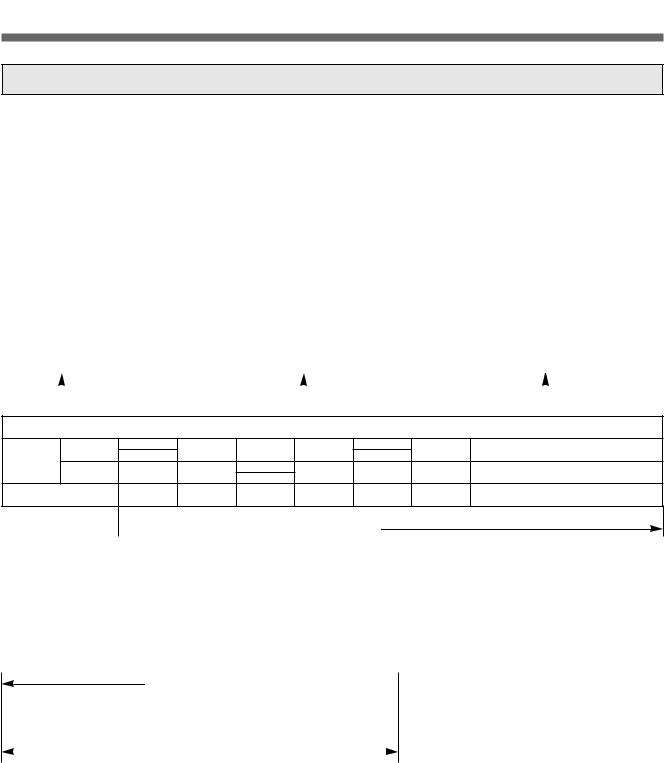
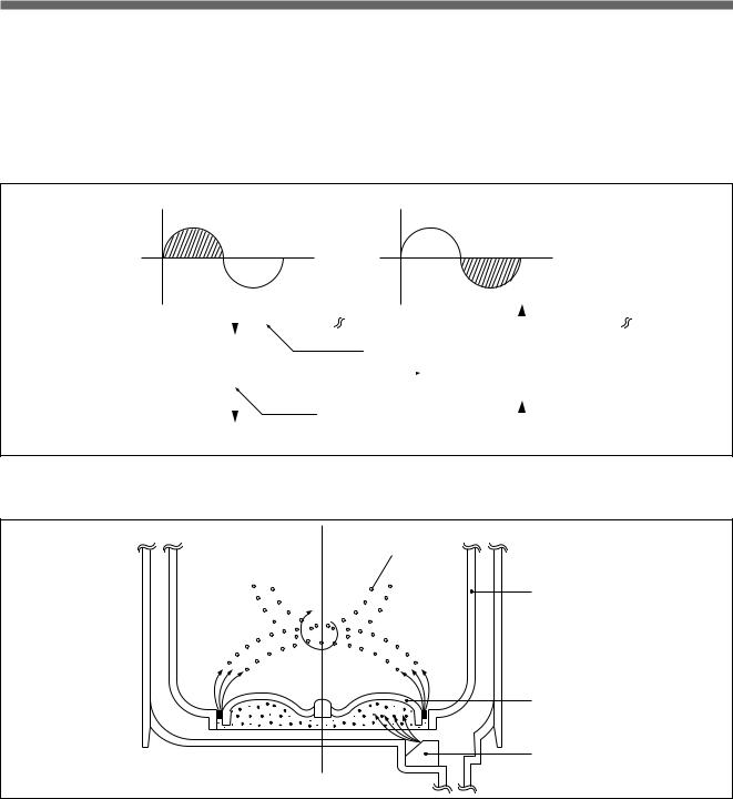
WATER CURRENT TO ADJUST THE UNBALANCED LOAD
It is a function to prevent eccentricity of the clothes after wash by rotating pulsator C.W and C.C.W for 20 seconds. (But, the DRY & SILK course have no operation of the water currents to adjust the unbalanced load.)
EFFECT
It reduces vibration and noise effectively while spinning.
WATER FLOW
|
WASH |
I |
DRAIN |
SPIN |
FILL |
RINSE 1 |
I |
DRAIN |
SPIN |
FILL |
RINSE 2 |
I |
DRAIN |
… |
|||
MOTOR C.W
SIGNAL C.C.W
|
TIME (SEC.) |
0.3 |
0.5 |
0.3 |
0.5 |
0.3 |
0.5 |
 20 SEC. (About 13 Times)
FUNCTION FOR SOAK WASH
DISPLAY THE RESIDUAL TIME
When the SOAK WASH is selected, the total wash time increases because 30 minutes for soak process are added to the time of main process.
PROGRESS
SOAK PROCESS 
 MAIN PROCESS
|
FILL |
WASH |
STOP |
WASH |
STOP |
WASH |
STOP |
|||||||
|
• |
2′ |
I |
8′ |
2′ |
I |
8′ |
2′ |
I |
8′ |
||||
|
30 Minutes |
|||||||||||||
NOTE: ‘ I ’ mark indicates the operation of the water currents to adjust the unbalanced load.
AUTOMATIC WATER SUPPLY SYSTEM FOR BLANKET WASH
The water level would be lowered because the blanket absorbs water at the beginning of washing. Therefore, after 30 seconds, the operation is interrupted to check the water level, and then the water is supplied again until the selected water level is reached.
3
Residual drain time.
The time remembered by micom.
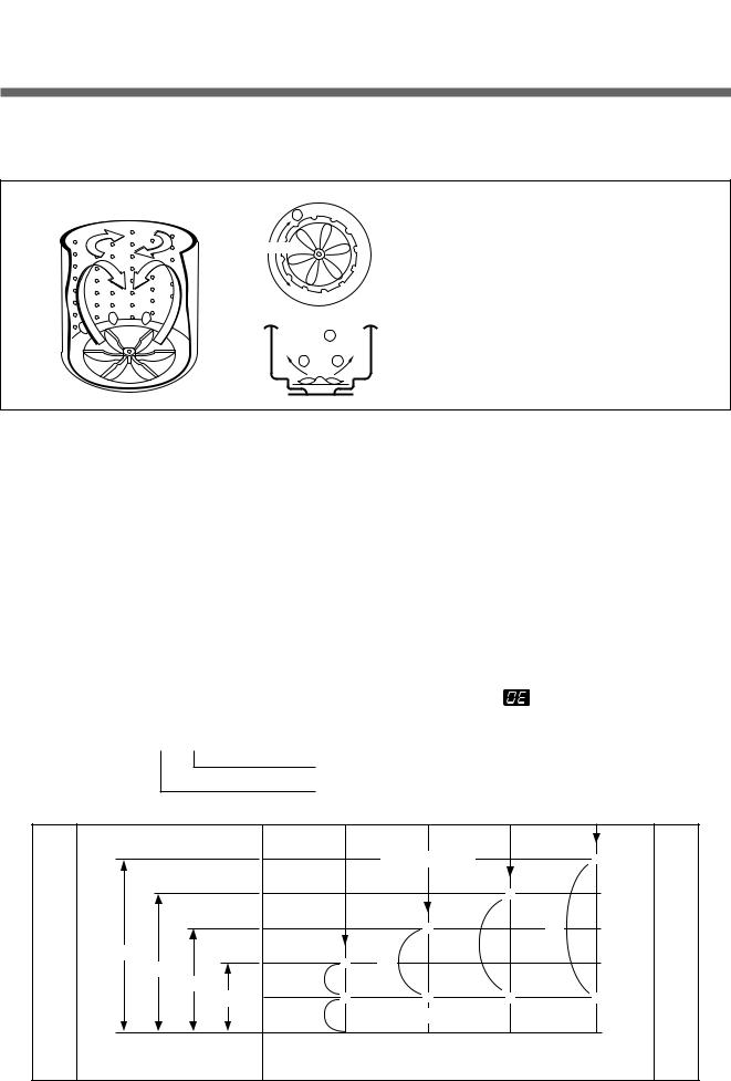
PULSATOR SYSTEM
When the new shaped pulsator is rotated C.W C.C.W at a high speed, it makes the ‘heart-shaped’ water currents as shown below.
C
Rotate
 B
B
A A
WATER CURRENTS
AWater is pushed up near the tub wall by rotation on the pulsator.
BWater is pulled down in the middle of the tub by rotation of the pulsator
CWater currents is generated by rotation of the pulsator.
AUTOMATIC DRAINING TIME ADJUSTMENT
This system adjusts the draining time automatically according to the draining condition.
|
Good draining |
The washer begins spin process after drainage. |
||
|
Draining |
|||
|
Bad draining |
Draining time is prolonged. |
||
|
condition |
|||
|
No draining |
Program is stopped and gives the alarm. |
||
FUNCTIONAL PRINCIPLE
1) The micom can remember the time from the beginning of drain to reset point when the pressure switch reaches to «OFF» point.
|
Drain Time |
Movement of the program |
|
|
Less than 4 minutes |
Continue draining. |
|
|
More than 4 minutes |
Program stops and gives the alarm with the |
blinked on display lamp. |
2) In case of continuous draining, residual drain time is determined by micom. Draining time as a whole=D + 60
(T sec.)
|
D |
(mm) |
W |
||||||
|
TRIP POINTS |
* |
345 |
||||||
|
R |
A |
|||||||
|
A |
* |
290 |
T |
|||||
|
I |
E |
|||||||
|
N |
D4 |
235 |
R |
|||||
|
I |
* |
L |
||||||
|
N |
T4 |
D3 |
||||||
|
G |
* |
D2 |
180 |
E |
||||
|
T3 |
D1 |
|||||||
|
T2 |
V |
|||||||
|
T |
T1 |
* |
* |
* |
* |
60 |
E |
|
|
I |
60 |
RESET POINTS |
L |
|||||
|
M |
0 |
|||||||
|
E |
E. LOW |
LOW |
MED |
HIGH |
T1=D1+60 (Sec.) T2=D2+60 (Sec.) T3=D3+60 (Sec.) T4=D4+60 (Sec.)
4
SOFTENER DISPENSER
This is the device to dispense the softener automatically by centrifugal force.
This is installed inside the auto-balancer.
FUNCTIONAL PRINCIPLE
1)Softener stays in room (A) when poured into softener inlet.
2)Softener moves from (A) to (B) by centrifugal force during intermittent spin process.
3)Softener flows from (B) to (C) during rinse process next to intermittent spin.
4)Softener moves from (C) to (D) by centrifugal force during second intermittent spin. After spin process is finished, the softener is added into the tub through softener outlet.
FLOW OF THE SOFTENER
|
Wash |
Intermittent |
Hold |
Intermittent |
Rinse |
Spin |
|||||||||
|
Spin |
Spin |
|||||||||||||
|
Normal |
Centrifugal |
Flow in |
Centrifugal |
Flow in |
||||||||||
|
force |
force |
|||||||||||||
|
Course |
(A) |
(B) |
(C) |
(D) |
||||||||||
|
FLOW OF THE SOFTENER INSIDE OF THE BALANCER |
||||||||||||||
|
Room inside |
A |
B |
C |
D |
||||||||||
|
the balancer |
||||||||||||||
Centrifugal force  Flowing by weight
NOTE: Softener moves into the next room when r.p.m. of the tub is more than 100 r.p.m.
HOW TO CHECK MOVEMENT
Pour a reasonable amount of «MILK» into softener dispenser and operate the washer with no load. In final rinse cycle, make sure that the milk is added into the tub through softener outlet.
Balancer
Softener
B outlet
D
A C
Softener inlet
5
AUTOMATIC UNBALANCE ADJUSTMENT
This system is to prevent abnormal vibration during intermittent spin and spin process.
FUNCTIONAL PRINCIPLE
1)When the lid is closed, the safety switch contact is «ON» position.
2)In case that wash loads get uneven during spin, the outer tub hits the safety switch due to the serious vibration, and the spin process is interrupted.
3)In case that P.C.B. ASS’Y gets «OFF» signal from the safety switch, spin process are stopped and rinse process is started automatically by P.C.B. ASS’Y.
4)If the safety switch is operated due to the unbalance of the tub, the program is stopped and the alarm is given.
Contact of safety switch Lid closing
Lid opening
|
Contact lever A |
|
|
Position of |
|
|
unbalanced |
|
|
load(OFF) |
Normal(ON) |
NOTE:
The alarm finished when you close the lid after opening it. Check the unbalance of the wash load and the installation condition.
CIRCULATING-WATER COURSE AND LINT FILTER
CIRCULATING-WATER
The washing and rinsing effects have been improved by adopting the water system in which water in the tub is circulated in a designed pattern.
When the pulsator rotates during the washing or rinsing process, the water below the pulsator vanes creates a water currents as shown in figure.
The water is then discharged from the upper part of the tub through the water channel.
About 40L/min. water is circulated at the ‘high’ water level, standard wash load and standard water currents.
Tub
Filter
Outer tub
Water
channel
Pulsator
6
LINT FILTER
Much lint may be obtained according to the kind of clothes to be washed and some of the lint may also sticks to the clothes.
To minimize this possibility a lint filter is provided on the upper part of the tub to filter the wash water as it is discharged from the water channel. It is good to use the lint filter during washing.
|
Bleach inlet |
Filter |
Pulsator |
HOW TO CLEAN THE LINT FILTER
1)Pull the filter frame upward.
2)Turn the lint filter inside out, and wash the lint off with water.
3)Return the filter as it was, and fix the filter frame to the slot.
RESIDUAL TIME DISPLAY
When the START/HOLD button is pressed, the residual time (min.) is displayed on the time indicator, and it will be counted down according to the process.
When operation is finished, the TIME INDICATOR will light up  .
.
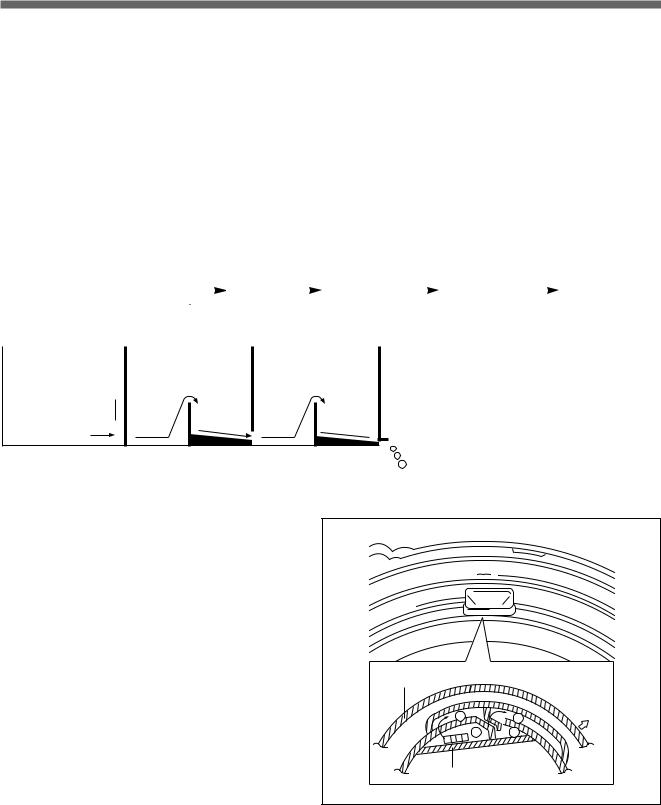
DRAIN MOTOR
STRUCTURE
Pull
Loosen
Pulley
Lever
Inductive ring
Magnet
Coil of motor
Magnet of motor
FUNCTIONAL PRINCIPLE
1)When the DRAIN MOTOR connected to the power source (AC 220V), the DRAIN MOTOR rotates with 900 r.p.m and revolves the pulley by gear assembly for reducing.
2)When the pulley is rotated, the pulley winds the wire to open the drain valve.
3)Therefore, rotation of pulley is changed to the linear moving of wire.
4)The wire pulls the brake lever of Gear Mechanism Ass’y within 5 seconds.
5)After the wire pulled, gear assembly is separated from motor and condition of pulling is held by operation of the lever.
6)When the power is turned off, the drain valve is closed because the wire returns to original position.
7
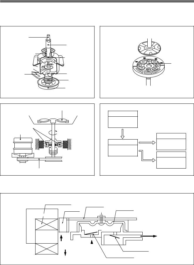
GEAR MECHANISM ASS’Y
The proper water currents is made by the rotation of pulsator at a low speed (about 145 r.p.m) to prevent the damage to the small sized clothes.
Pulsator shaft
|
Spinner shaft |
|
|
Inner clutch spring |
|
|
Planetary gear |
|
|
Brake lever |
Clutch spring |
|
Clutch boss |
|
|
Spinner pulley |
Sun gear
Planetary gear
 Internal gear
Pulsator
|
Planetary |
|
|
Motor |
1 revolution |
5.2 revolutions

 Spinner
pulley
V-belt
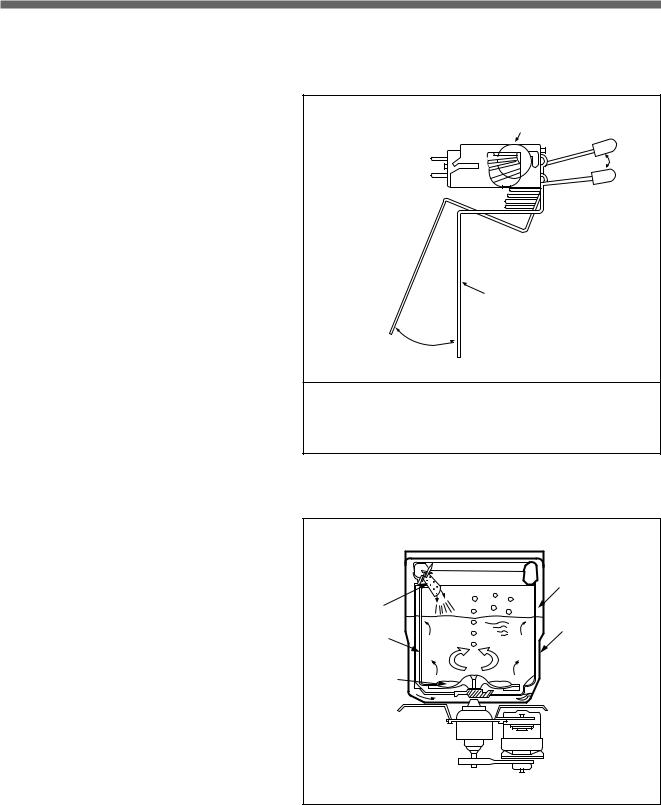
PRINCIPLE OF BUBBLE GENERATOR
STRUCTURE
|
Motor |
||
|
1490 r.p.m. |
||
|
60(Hz) |
||
|
V.belt |
Pulsator |
|
|
Planetary |
||
|
Gear |
||
|
Spinner Pulley |
145 r.p.m. |
|
|
1/5.2 |
||
|
775 r.p.m. |
Tub |
|
|
Directly |
775 r.p.m. |
|
|
Bobbin & coil |
Armature |
|
Magnet |
Bellows |
|
Trans core |
Air out hole
|
Protector A |
|||
|
Air in hole |
|||
|
Protector B |
|||
8
PRINCIPLE OF INTAKE & OUTLET OF THE AIR
INTAKE : ARMATURE moves up, and BELLOWS inhales the air. At the same time, protector B is open and A is close. OUTLET: ARMATURE moves down, and BELLOWS exhausts the air. At the same time, protector B is close and A is
open.
FUNCTIONAL PRINCIPLE OF TRANS & MAGNET
•The phase of A.C electric power changes to 60 cycle/second.
•The magnetic pole of trans core is changed by the change of the phase of A.C electric power.
•The core repeats push and pull (3600 times/min.) of the armature magnet.
|
N |
Pan spring |
N |
||||||||||||
|
NS |
NS |
|||||||||||||
|
Trans core |
||||||||||||||
|
S |
Magnet |
S |
||||||||||||
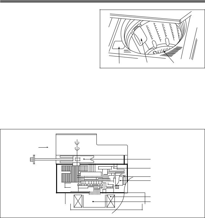
FUNCTIONAL PRINCIPLE OF BUBBLE WASHING MACHINE
CROSS SECTION
Air bubble
Tub
 Outer tub
Pulsator
Nozzle
FUNCTIONAL PRINCIPLE
Bubble generator supplies the air from the bottom of outer tub to the inner space of pulsator, the air is dispersed by the rotation of pulsator. Air-bubble is created by the centrifugal force, and rises up.
9
![]()
3. STRUCTURE OF THE WASHING MACHINE
STRUCTURE OF THE WASHING MACHINE
|
• HOT WATER TAP |
• COLD WATER TAP |
After using the washer, close the water tap and turn off the power.
• SOFTENER INLET
Pour softener into the softener inlet just before wash and it will be added into the tub automatically just before the final rinse.
•BLEACH INLET
•CONTROL PANEL
•SCREW COVER
•TUB
After using the washer, close the water tap and turn off the power.
 • GUIDE
DRAIN HOSE
• POWER SWITCH
• HOOK HOLE
• LINT FILTER
• DRAIN HOSE
• HANDLE
• POWER CORD
•ADJUSTABLE LEGS
ACCESSORIES
|
Inlet Hose |
Water Tap |
Drain Hose |
Hose Fixture |
Drain Hose |
Guide Drain Hose |
|
(2 Pcs) |
Adapter (2 Pcs) |
Clamp |
In case of screw-shaped
inlet hoses, water tap adapters will not be provided.
10

4. FUNCTION OF THE CONTROL PANEL
FUNCTION OF THE CONTROL PANEL
CONTROL PANEL
It has micom sensor.
As the buttons are pressed, the lamps indicating
the selection of you desired washing program will light up.
|
Power Switch |
Cancel Button |
||||
|
• Press this switch to turn the |
• With this button, you can arbitrarily |
||||
|
choose course by proper |
|||||
|
power ON or OFF. |
|||||
|
combination with the right three |
|||||
|
• After turning off the power, |
buttons. |
||||
|
• If you want the washer to operate |
|||||
|
wait for more than 3 |
|||||
|
differently from presetting time or to |
|||||
|
seconds and then turn it on |
|||||
|
POWER |
operate separately among the three |
||||
|
again. |
|||||
|
stages, you first push this button |
|||||
|
and other buttons sequentially. |
|||||
DAEWOO AUTOMATIC
WASHER
AERO FUZZY & AIR POWER
DRY CLEANING EFFECT
CANCEL WASH
Display
•The “TIME” part lamp indicates the residual time and the number of rinsing and spinning times until wash is over.
•The “COURSE”, “TEMP”, and “LEVEL” part lamps are turned on according to the buttons of the control panel.
|
TIME |
COURSE |
TEMP.LEVEL |
|||||
|
SOAK WASH RINS |
SPIN FUZ. |
DRY |
SILK |
SOAK |
HOT H. |
||
|
D |
WARM |
M. |
|||||
|
MIN. TIME |
MIN. |
SPEE |
STRO |
NIGHT |
BLAN |
L. |
|
|
* |
COLD |
||||||
|
D |
S. |
||||||
|
* |
|||||||
|
RINSE |
SPIN |
COURSE WASH |
TEMP |
|||
Start/Hold Button
•Press this button to begin operation or to stop operation temporarily.
•Operation and temporary stop are repeated as it is pressed.
START/HOLD
WATER LEVEL
Wash Selector
•The above three buttons can be used to bring the three washing stages under control.
Course Selection Button
•This button is used to select the washing course according to the type of the clothes being washed.
•You can choose one of the eight courses by pressing this button until your desired course indicator light comes on.
Temperature Selection Button
•This button is used to select the water temperature according to the clothes being washed.
•Press this button until your desired temperature indicator light comes on, and it will repeat following signs:
COLD ¤A WARM ¤A HOT
Water Level Selector
•This selector is used to select the washing water level according to the size of the wash load.
11

5. DIRECTION FOR INSTALLATION AND USE
DIRECTION FOR INSTALLATION AND USE
TO INSTALL THE WASHING MACHINE
SELECTION OF THE INSTALLING PLACE
Install the washer on a horizontal solid floor.
If the washer is installed on an unsuitable floor, it could make considerable noise and vibration.
Never install in these places
•The place where it would be exposed to direct sunlight.
•The place nearby a heater or heat appliance.
•The place where it would be supposed to be frozen in winter.
•The kitchen with coal gas and a damp place like a bathroom.
•The proper installation of the washing machine can increase the wash effectiveness and the life of it.
|
INSTALLATION OF THE UNDER BASE COVER |
After installing the washing machine, close the under-base cover. |
!The packing box opened, there is a under-base cover at the bottom of the back.
@Push the under-base cover into the end, which decreases the noise made by this washer.
HOW TO INSTALL ON AN INCLINED PLACE
If the washer is installed on an unsuitable floor, it could make considerable noise and vibration, and could cause a malfunction.
Use the height adjust rubber to adjust the washing machine so that it sits properly.
|
!Height Setting |
@Check the Horizontal Status |
||||
|
• After controlling the height by |
• Check the position of tub above |
||||
|
turning the adjustable legs, let the |
the center of the washer. |
||||
|
washer put down to the ground. |
|||||
NOTES:
The opening must not be obstructed by carpeting when the washing machine is installed on a carpeted floor.
13
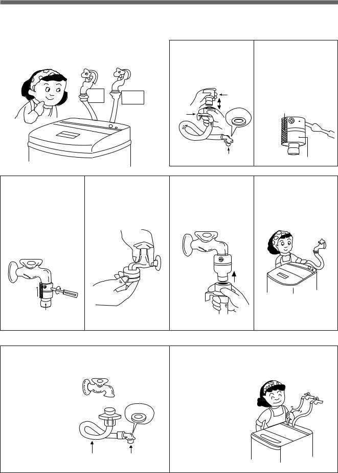
HOW TO CONNECT THE INLET HOSE
IN INSTALLING THE INLET HOSE
Be careful not to mistake in supplying hot and cold water.
In using only one water tap, connect the inlet hose to the cold water inlet.
|
Hot |
Cold |
|
|
Water |
||
|
Water |
||
!Pull down the collar of the inlet hose to separate it from the water tap adapter.
|
Water Tap |
||
|
Adapter |
||
|
Collar |
Rubber |
|
|
packing |
||
Connector C
@Loosen the four screw at the water tap adapter, but don’t loosen the screws until they are separated from the water tap adapter.
Tape
 Connector A
Tap 
Adapter
Connector B
#Connect the water tap adapter to the water tap, and tighten the four screws evenly while pushing up the adapter so that the rubber packing can stick to the water tap tightly.
@
!
Connector B
$Remove the tape, and screw connector B into connector A tightly.
%Connect the inlet hose to the water tap adapter by pulling down the collar of the hose end.
Collar
^Connect the connector C of the inlet hose to the water inlet of the washer by turning it clock-wise to be fixed tightly.
•Please check the rubber packing inside the connector C of the inlet hose.
• FOR SCREW-SHAPED TAP
!Connect the inlet hose to the water tap by screwing the connector D tightly.
Connector D
Hose
Rubber
Packing
Connector C
@Connect the connector C of the inlet hose to the water inlet of the washer by turning it clockwise to be fixed tightly.
•Please check the rubber packing inside the connector C of the inlet hose.
14

HOW TO USE THE DRAIN HOSE (FOR DWF-5590D SERIES)
NOTE IN USING THE DRAIN HOSE
!In case that it goes over a doorsill.
Don’t let the height of the drain hose exceed 20cm from the ground.
@Inhose.case of extending the drain Don’t let the total length exceed 3m.
#Be careful that the end of the drain hose is not immersed in water.
15

HOW TO INSTALL THE DRAIN HOSE (FOR DWF-5590DP SERIES)
NOTE IN USING THE DRAIN HOSE
Never forget to install drain hose before operating this washing machine.
There are a drain hose, a hose clamp, a hose fixture and a hose guide in the washing machine.
|
!Connect the drain hose to the |
@Insert the hose fixture into hook |
|
drain outlet at the back side of |
hole at the side of the body, |
|
the washing machine, and |
and fix the drain hose by |
|
fasten it tightly with the clamp |
inserting it into the hose fixture. |
|
supplied. |
Drain Output
Hook Hole
Drain hose
Hose Fixture
Drain Hose
Hose Clamp
|
$Hook the drain hose to the |
Or, connect the drain hose to a |
|
|
standpipe of a diameter greater than |
||
|
edge of the tub, paying |
||
|
attention that there are no |
that of the drain hose and at a height |
|
|
bends or constractions along |
of min. 70cm. |
|
|
the drain hose. |
70cm min
#Attach the hose guide, included in the accessory kit, to guide the drain hose over the tub or standpipe.
Pull Hose through 
|
Flex. Hose |
55 mox |
|
Guide |
|
|
apart |
%Position the washing machine next to the wall.
MUST be ventilated
NOTES:
1.Keep the drain hose fixed tightly in the hose fixture, or let the highest point of the drain hose be more than 1m above the floor.
If not so, the water in the washer could be drained during operation
2.Be sure that the height of the drain hose must be less than 1.5m above the floor. If not so, the water in the washer could not drain.
3.The hose guide MUST be fitted to the drain hose. The drain hose sould not extend more than 55mm from the end of the hose guide. This is to prevent ‘SYPHONING’.
If necessary the drain hose can be trimmed to length.
16
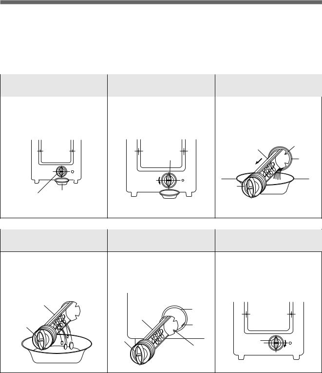
HOW TO CLEAN DRAIN FILTER (FOR DWF-5590DP SERIES)
In this washer machine, the drain filter is equipped at the back side of it.
This drain filter is to screen the foreign stuffs such as threads, coins, pins, buttons etc..
And this should be cleaned frequently (every 5 times of use) for its smooth operation.
Drain problem could be caused if the drain filter is not cleaned at proper time.
Please keep it clean.
In case you clean the drain filter, please follow the instructions as below.
|
!Remove the |
@ Unscrew the cap. |
#Release the filter |
|
|
remained water |
assembly |
||
|
• Put down the remained water in |
• Turn the cap counter clockwise. |
• Pull out the filter assembly off the |
|
|
the hose. And put a container |
case of the main body. |
||
|
under the filter to collect water. |
|||
|
FILTER |
SLIT |
||
|
CAP |
CASE |
||
|
CAP |
|||
|
FILTER CONTAINER |
|
$Remove the |
%Put the filter |
^ Lock the cap. |
|
foreign stuffs |
assembly back |
|
|
• Clean the drain filter removing the |
• Put in the filter along the guiding |
• Turn the cap clockwide tightly. |
|
foreign stuffs. |
prominence of the case. Please |
|
|
note the right position of the filter |
||
|
adjusting the groove to the guide |
||
|
rib. |
||
|
FILTER |
||
|
CASE |
||
|
FILTER |
||
|
CAP |
GUIDE |
|
|
RIB |
||
|
CAP |
CAP |
|
|
SLIT |
NOTES: During the operation, the «OE» signal means drain error can be displayed on the control panel. In this case, the main cause of that problem is the blocking of the drain filter.
If you clean the drain filter following above instructions, you could continue the normal operation of the washing machine to reset the program, please turn the power off and on again.
17
6. PROCEDURE OF FULL-AUTOMATIC WASHING
PROCEDURE OF FULL-AUTOMATIC WASHING
Prepare for washing.
¡Ø
Pressing the power switch
¡Ø
Put the clothes into the tub.
¡Ø
Select the washing course.
|
¤ Full-Automatic |
¤ŁSelect the Course |
¤ØProcedure of |
|||||||||||||||||
|
Pressing the Button |
|||||||||||||||||||
|
BLANKET |
|||||||||||||||||||
|
This selection is effective |
BLANKET |
START/HOLD |
|||||||||||||||||
|
for blanket, curtain, |
|||||||||||||||||||
|
SOAK |
WASH |
RINS |
SPIN |
||||||||||||||||
|
carpet, etc.. |
|||||||||||||||||||
|
* 3 kg’s limitation |
|||||||||||||||||||
|
MIN. |
TIME |
MIN. |
for one-time-wash. |
COURSE |
|||||||||||||||
|
FUZZY |
START/HOLD |
||||||||||||||||||
|
This selection is for |
|||||||||||||||||||
|
FUZZY |
|||||||||||||||||||
|
(SENSOR) |
general washing. |
||||||||||||||||||
|
DRY |
This selection is effective |
DRY |
|||||||||||||||||
|
for delicate clothes. |
Put the exclusive |
||||||||||||||||||
|
SOAK |
WASH |
RINS |
SPIN |
||||||||||||||||
|
* Just follow the washing |
detergent, dryten of |
||||||||||||||||||
|
procedure. |
26g into the tub for |
||||||||||||||||||
|
* 1.5kg’s limitation |
dilution with water. |
||||||||||||||||||
|
MIN. |
TIME |
MIN. |
for one-time-wash. |
COURSE |
|||||||||||||||
|
SILK |
|||||||||||||||||||
|
This selection is effective for |
SILK |
||||||||||||||||||
|
some clothes made of silk. |
Put the exclusive |
||||||||||||||||||
|
SOAK |
WASH |
RINS |
SPIN |
||||||||||||||||
|
* Do not put in the wash marked |
detergent, dryten of |
||||||||||||||||||
|
with ‘dry-cleaning’. |
26g into the tub for |
||||||||||||||||||
|
* 1kg’s limitation for one-time- |
dilution with water. |
||||||||||||||||||
|
MIN. |
TIME |
MIN. |
wash. |
COURSE |
|||||||||||||||
|
STRONG |
STRONG |
START/HOLD |
|||||||||||||||||
|
The selection is effective |
|||||||||||||||||||
|
SOAK |
WASH |
RINS |
SPIN |
for blue-jean, climbing |
|||||||||||||||
|
clothes, ruck-sack, sports |
|||||||||||||||||||
|
MIN. |
TIME |
MIN. |
wear, etc.. |
||||||||||||||||
|
COURSE |
|||||||||||||||||||
|
NIGHT |
NIGHT |
START/HOLD |
|||||||||||||||||
|
This selection is for a |
|||||||||||||||||||
|
SOAK |
WASH |
RINS |
SPIN |
night-washing housewife |
|||||||||||||||
|
who has no opportunity at |
|||||||||||||||||||
|
day time. |
|||||||||||||||||||
|
MIN. |
TIME |
MIN. |
COURSE |
||||||||||||||||
|
SOAK |
|||||||||||||||||||
|
This course is used to |
SOAK |
START/HOLD |
|||||||||||||||||
|
increase the wash effect by |
|||||||||||||||||||
|
SOAK WASH |
RINS |
SPIN |
|||||||||||||||||
|
keeping the clothes soaked |
|||||||||||||||||||
|
sufficiently in the wash |
|||||||||||||||||||
|
MIN. |
TIME |
MIN. |
water. |
COURSE |
|||||||||||||||
|
SPEED |
SPEED |
START/HOLD |
|||||||||||||||||
|
This selection is effective |
|||||||||||||||||||
|
SOAK |
WASH |
RINS |
SPIN |
||||||||||||||||
|
for washing light or less |
|||||||||||||||||||
|
MIN. |
TIME |
MIN. |
dirty wash. |
COURSE |
|||||||||||||||
*As far as putting the power plug out, the selections for hot and cold water are remembered after washing. At next washing time, the remembered lamp will light on.
18
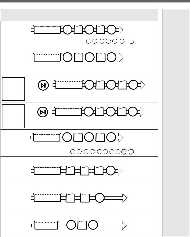
¤ŒProcedure of Washing (Washing machine does it automatically.)
|
Water inlet and |
SPIN |
RINSE |
SPIN |
RINSE |
SPIN |
|||||
|
wash for 14 minutes. |
||||||||||
|
A Blanket course’s water flow is |
R |
R |
L |
L |
R |
L |
||||
|
Water inlet and |
SPIN |
RINSE |
SPIN |
RINSE |
SPIN |
|||||
|
wash for 14 minutes. |
||||||||||
|
Artificial brain computer controls full procedure proper to wash load |
||||||||||
|
automatically. |
||||||||||
|
Buzzer signal to |
START/HOLD |
|||||||||
|
notify you can put |
Water inlet and |
SPIN |
RINSE |
SPIN |
RINSE |
SPIN |
||||
|
the sensible |
wash for 6 minutes. |
|||||||||
|
clothes into the |
||||||||||
|
diluted water with |
A part of dotted line is decreasing rotation velocity. |
|||||||||
|
Dryten. |
Because protect clothes from damage. |
|||||||||
|
Buzzer signal to |
START/HOLD |
|||||||||
|
notify you can put |
Water inlet and |
SPIN |
RINSE |
SPIN |
RINSE |
SPIN |
||||
|
the sensible |
wash for 4 minutes. |
|||||||||
|
clothes into the |
||||||||||
|
diluted water with |
A part of dotted line is decreashing rotation velocity. |
|||||||||
|
Dryten. |
Because protect clothes from damage. |
|||||||||
|
Water inlet and |
SPIN |
RINSE |
SPIN |
RINSE |
SPIN |
|||||
|
wash for 14 minutes. |
||||||||||
|
A strong course’s water flow is R |
L |
R |
L |
R L |
R |
L |
R |
L |
|
Water inlet and |
RINSE |
RINSE |
RINSE |
SPIN |
|
|
wash for 30 minutes. |
|||||
|
Water inlet and |
RINSE |
RINSE |
SPIN |
|
|
wash for 44 minutes. |
||||
|
Water inlet and |
SPIN |
RINSE |
SPIN |
|
|
wash for 10 minutes. |
||||
After Washing: • Close the water tap and separate it from the inlet-hose.
If not so, the autovalve is out of order by the water pressure.
• Take off plug.
End of washing informed by buzzer.
After 10 minutes later from the end of the washing the power switch is turned off
automatically.
19
Table of Contents for DAEWOO ELECTRONICS DWF-5590DP Series:
-
6. PROCEDURE OF FULL-AUTOMATIC WASHING 18 PROCEDURE OF FULL-AUTOMATIC WASHING Prepare for washing. ¡Ø Pressing the power switch ¡Ø Put the clothes into the tub. ¡Ø Select the washing course. BLANKET This selection is effective for blanket, curtain, carpet, etc.. * 3 kg’s limitation for one-time-wash. FUZZY (SENSOR) This selection is for general washing. BLANKET START/HOLD COURSE FUZZY START/HOLD DRY C
-
24 CONCERNING DRAINING PROBLEM CHECK POINT CAUSE SOLUTION THE WASHER DOES NOT DRAIN. YES Close the lid. Safety switch is defective Change the safety switch. Is the connector of P.C.B AS connectsd properly? Change P.C.B ASS’Y. Improper installation YES Install drain hose properly. NO YES Is the lid open? Does the safety switch operate normally? Improper connection of the connector Connect the connector properly. P.C.B ASS’Y is defective Do you put down the drain hose? Does the drain motor operate normally? Drain problem
-
Downloaded from www.Manualslib.com manuals search engine
-
BARE PCB (BOTTOM)BARE PCB (TOP) 6564 Downloaded from www.Manualslib.com manuals search engine
-
21 DRAIN MOTOR BRAKE ADJUSTMENT • Lay the front of the washer on the floor. • Remove three bolts mounting the drain motor. • Take out the wire of drain motor from the link brake. Link brake Wire Drain Motor • Loosen the adjustment bolt and turn the adjustment bolt until the end of the bolt touches to the brake lever. • Tighten the lock nut and apply a small amount of paint-lock. Brake lever Adjustment bolt Gear mechanism ass’y Clutch lever
-
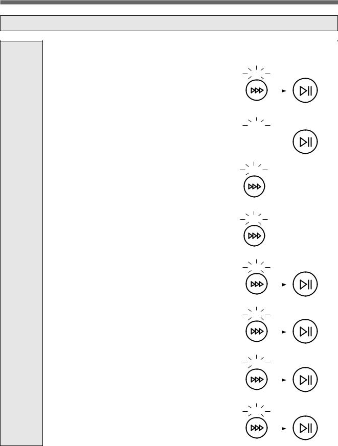
CONVENIENT TEST FUNCTION COURSE 1 Keep pushing three button (WASH, RINSE, SPIN) together and turn on the power switch. COURSE 2 Processing COURSE 1, Push the SPIN button according to table, then you can check each part quickly. 28 DISPLAY FUNCTION A : Display of Load Data 1 B : Display of Model Initial lighting status. 2 LO: display that temparature sensor is not installed. ALL LED light 8 times and go back to 3 first stage. Ti
-
MINUTE EXPLANATION DIAGRAM FOR EACH PARTS MICOM IC (64 DIP) 29 1 2 3 4 5 6 7 8 9 10 11 12 13 14 15 16 17 18 19 21 21 22 23 24 25 26 27 28 29 30 31 32 P10/S00 P11/SI0/SB0 P12/SCK0 P13/S01 P14SI1/SB1 P15/SKC1 P16/BUZ P17/PWM TEST1 RES XT1 XT2 VSS CF1 CF2 VDD P80/AN0 P81/AN1 P82/AN2 P83/NT3 P7/INT0 P71/INT1 P72/INT2/T0IN P73/INT3/T0IN S0/T0 S1/T1 S2/T2 S3/T3 S4/T4 S5/T5 S6/T6 S7/T7 64 63 62 61 60 59 58 57 56 55 54 53 52 51 50 49 48 47 46 45 44 43 42 41 40 39 38 37 36 35 34 33 P07 P06
-
2) DETAIL EXPLANATION OF CIRCUIT ACTION (ACTION OF CW WASH) •In case MICOM terminal No. 31 is ‘H’ and No. 6 is ‘L’, Q14(C3202Y) & Q15 (A1271Y) turn on and control the TRIAC. The resistance, as 62 Ω & 1/2W, of R52 is used to limit the GATE current of the TRIAC. •The resistance R38 (3.9KΩ, 1/4W) and R45 (1KΩ, 1/4W) control the base current of Q14 & Q15 in order as TR forces to turn on sufficiently. •The ceramic conde
-
• The Electrolytic condenser C13(3300µF, 10V) and diode D2 is used in order that at instant power supply failure circuit should remember the contents of the program. It happens that the MICOM terminal No. 16 has instant interruption of electric power, yet the MICOM is not discharged electricity because of the diode D2. • The measurement of voltage 3) CAUTION FOR A/S • Measure the voltage of input terminal REGULATOR I. C. of 7806 with tester. And, compare the measuring value with the voltage table. • Check the condense
-
PARTS LIST (DWF-5590DP SERIES) 45 REF No. PART CODE PART NAME DESCRIPTION Q’TY REMARK P01 3614508200 PLATE T ABS 1 ONLY P02 3614203000 PANEL F ABS 1 ONLY P03 3614207700 PANEL B ABS 1 ONLY P04 3611703401 DOOR B ABS 1 ONLY P05 3611403100 COVER DOOR ABS 1 COMMON 6670 P06 3615500500 WINDOW DISPLAY ABS 1 COMMON 6670 P07 PRESSWEG00 PCB ASSY DWF-5590DPN, DPM 1 PRPSSWGM00 DWF-5590DPT, DPS 5EP4054821 T3-V2F (220-240V/50Hz) P08 5EP4054801 TRANS POWER T3-V2(220-240V/50Hz) 1 5EP4
-
CONCERNING OPERATION 26 PROBLEM CHECK POINT CAUSE SOLUTION THE INDICATOR LAMP (LED) DOES NOT LIGHT UP WHEN THE POWER S/W IS PRESSED NO Connect the plug Press the power switch YES Is the plug connected to electric outlet? Is the power switch pressed? Power switch is defective. Change power switch NO NO Is the condition of power switch good? YES Improper connection of the connector. Connect the connector properly NO Is the connector of the P.C.B. A
-
SOFTENER DISPENSER This is the device to dispense the softener automatically by centrifugal force. This is installed inside the auto-balancer. FUNCTIONAL PRINCIPLE 1) Softener stays in room (A) when poured into softener inlet. 2) Softener moves from (A) to (B) by centrifugal force during intermittent spin process. 3) Softener flows from (B) to (C) during rinse process next to intermittent spin. 4) Softener moves from (C) to (D) by centrifugal f
-
5. DIRECTION FOR INSTALLATION AND USE TO INSTALL THE WASHING MACHINE SELECTION OF THE INSTALLING PLACE Install the washer on a horizontal solid floor. If the washer is installed on an unsuitable floor, it could make considerable noise and vibration. • The proper installation of the washing machine can increase the wash effectiveness and the life of it. INSTALLATION OF THE UNDER BASE COVER After installing the washing machine, close the under-base cover. If the washer is installe
-
15 HOW TO USE THE DRAIN HOSE (FOR DWF-5590D SERIES) NOTE IN USING THE DRAIN HOSE ! In case that it goes over a doorsill. Don’t let the height of the drain hose exceed 20cm from the ground. @ In case of extending the drain hose. Don’t let the total length exceed 3m. 20cm 3m # Be careful that the end of the drain hose is not immersed in water. Downloaded from www.Manualslib.com manuals search engine
-
61 REF NO. PART CODE PART NAME DESCRIPTION REMARK IC8 1UDN2981A- DRIVE IC UDN2981A SW3 5S50101400 SW TACT SKQBAD (KQD-902 1C 1P) SW4 5S50101400 SW TACT SKQBAD (KQB-902 1C 1P) SW5 5S50101400 SW TACT SKQBAD (KQD-902 1C 1P) SW6 5S50101400 SW TACT SKQBAD (KQD-902 1C 1P) SW7 5S50101400 SW TACT SKQBAD (KQD-902 1C 1P) SW8 5S50101400 SW TACT SKQBAD (KQD-902 1C 1P) SW9 5S50101400 SW TACT SKQBAD (KQD-902 1C 1P) SW12 5S50101400 SW TACT SKQBAD (KQD-902 1C 1P) D12 DKN4148— DIODE KN4148 AUTO 26MM PUM
Questions, Opinions and Exploitation Impressions:
You can ask a question, express your opinion or share our experience of DAEWOO ELECTRONICS DWF-5590DP Series device using right now.
-
DeWalt
DXPW3025
If you have questions or comments, contact us.Pour route question ou tout commentaire, nous contacter.Si tiene dudas o comentarios, cont_ctenos.iNSTRUCTiON MANUALGUIDE D’UTILISATIONMANUAL DE INSTRUCCIONESINSTRUCTIVO DE OPERACION, CENTROS DE SERVICIO Y P©LIZA DEGARANT[A. ADVERTENCIA: LEASE ESTE INSTRUCTIVO ANTES D …
DXPW3025 Washer, 67
-
Frigidaire
GLTF1040AS
InstallationInstructionsFull Size Tumble Action WashersBefore beginning installation, carefully read these instructions. This will simplify theinstallation and ensure the washer is installed correctly and safely. Leave these instructionsnear the washer after installation for future reference.NOTE: The electrical servi …
GLTF1040AS Washer, 6
-
Indesit
IWD 51231
GB1ContentsInstallation, 2-3-4-5Unpacking and levellingConnecting the electricity and water suppliesThe first wash cycleTechnical dataDescription of the washing machine and starting a wash cycle, 6-7Control panelIndicator lightsStarting a wash cycleWash cycles, 8Table of wash cyclesPersonalisation, 9Setting the tempera …
IWD 51231 Washer, 16
-
GE
G018
GEAppliances.comSafety Instructions ………. 2,sOperating InstructionsAppliance Communication ……… 9Care and Cleaningof the Washer ……………….. 10Features ……………………… 7Loading and Usingthe Washer …………………… 8Operating instructions ………. 4-6Troubleshooting Tips ….. 11- …
G018 Washer, 48
-
GE
GTWN8250DWS
Write the model and serial numbers here:Model # _____________Serial # ______________You can find them under the lid of the washer.GEAppliances.comOwner’s ManualWashers 49-90458 09-12 GESafety Instructions ……….2, 3Operating InstructionsAppliance Communication ….. 9, 10Care and Cleaning of the Washer .. …
GTWN8250DWS Washer, 32
-
Kenmore
501-40002
Sears, Canada Inc. Get it fixed, at your home or ours!Your HomeIn USA for repair–in your home–of all major brand appliances,lawn and garden equipment, or heating and cooling systems,no matter who made it, no matter who sold it!In Canada, for repair in your home of all major brandappliances, no matter who made …
501-40002 Washer, 44