-
Contents
-
Table of Contents
-
Bookmarks
Quick Links
MAKING MODERN LIVING POSSIBLE
Air handling Seq.
control algorithm
Software version 2.1
REFRIGERATION &
AIR CONDITIONING DIVISION
Danfoss Electronics spa
User manual
Related Manuals for Danfoss MCX08M
Summary of Contents for Danfoss MCX08M
-
Page 1
MAKING MODERN LIVING POSSIBLE Danfoss Electronics spa Air handling Seq. control algorithm Software version 2.1 User manual REFRIGERATION & AIR CONDITIONING DIVISION… -
Page 2: Table Of Contents
12.4| Fans lock Air quality control Alarms 14.1| Actions following an alarm 14.2| Types of reset 14.3| Alarms table Parameters DKRCC.PS.RI.A1.02 / 520H4358 — Air Handling Seq. user manual — V 2.2 Produced by Danfoss Electronics spa Graphic Department, 10-2009…
-
Page 3
17.1| Guide to modifying the application software 17.2| “Parameters” Page 17.3| “Alarms” Page 17.4| “Parameters_x_Model” Page 17.5| I/O configuration pages DKRCC.PS.RI.A1.02 / 520H4358 — Air Handling Seq. user manual — V 2.2 Produced by Danfoss Electronics spa Graphic Department, 10-2009… -
Page 4: Introduction
MMIMYK accessory, select the configuration to download onto the MCX on a case-by-case basis. DKRCC.PS.RI.A1.02 / 520H4358 — Air Handling Seq. user manual — V 2.2 Produced by Danfoss Electronics spa Graphic Department, 10-2009…
-
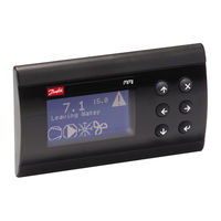
Page 5: User Interface
Passing from OFF to ON turns on the main screen. Activating of the digital and analog outputs is delayed, respectively, by the dOt and AOt times DKRCC.PS.RI.A1.02 / 520H4358 — Air Handling Seq. user manual — V 2.2 Produced by Danfoss Electronics spa Graphic Department, 10-2009…
-
Page 6: Main Screen
The main screen varies depending on whether a LED or LCD display is being used. 2.3.1| LED Display Fig 1_[User interface — LED display] DKRCC.PS.RI.A1.02 / 520H4358 — Air Handling Seq. user manual — V 2.2 Produced by Danfoss Electronics spa Graphic Department, 10-2009…
-
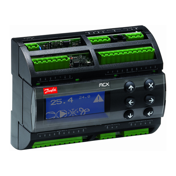
Page 7: Lcd Display
A” and “display B” for the version with LED display); » the symbols of the main active functions (see figure). Fig 2 _ [User interface — LCD display] DKRCC.PS.RI.A1.02 / 520H4358 — Air Handling Seq. user manual — V 2.2 Produced by Danfoss Electronics spa Graphic Department, 10-2009…
-
Page 8: Menu-Based Navigation
Unlock fans Winter Sets the winter operating mode Summer Sets the summer operating mode Tab 3 _ [User interface -Menu-based navigation] DKRCC.PS.RI.A1.02 / 520H4358 — Air Handling Seq. user manual — V 2.2 Produced by Danfoss Electronics spa Graphic Department, 10-2009…
-
Page 9: Displaying And Managing Alarms
The level for a given menu and the parameters is defined through the Configurator software. “ AHU_Interface_vNN.xls”. DKRCC.PS.RI.A1.02 / 520H4358 — Air Handling Seq. user manual — V 2.2 Produced by Danfoss Electronics spa Graphic Department, 10-2009…
-
Page 10: Parameters
If enabled through the Configurator software, makes it possible to access the input/output configuration screens. For each input/output for the instrument, it is possible to set the type, work field, polarity and function performed. DKRCC.PS.RI.A1.02 / 520H4358 — Air Handling Seq. user manual — V 2.2 Produced by Danfoss Electronics spa Graphic Department, 10-2009…
-
Page 11: Utilities
Unlock fans Sub-menu: WIN – Winter Sets the winter operating mode. Sub-menu: SUM – Summer Sets the summer operating mode. DKRCC.PS.RI.A1.02 / 520H4358 — Air Handling Seq. user manual — V 2.2 Produced by Danfoss Electronics spa Graphic Department, 10-2009…
-
Page 12
Heat seq. 2 power Humidification power Cool seq. 1 power Recovery (Mixing) power Tab 5 _ [Menu-based navigation — Screen description] DKRCC.PS.RI.A1.02 / 520H4358 — Air Handling Seq. user manual — V 2.2 Produced by Danfoss Electronics spa Graphic Department, 10-2009… -
Page 13: Configuring The Ahu Software
Define the control type, the control probe and if necessary the PID control parameters. (See “12] Supply and return fans”). DKRCC.PS.RI.A1.02 / 520H4358 — Air Handling Seq. user manual — V 2.2 Produced by Danfoss Electronics spa Graphic Department, 10-2009…
-
Page 14: Input/Output Configuration
Lock Fan Lock/Unlock fans Comf/Eco Comfort/Economy selection FreeHeatCool Freeheat/Freecool changeover Tab 7 _ [Configuring the AHU software — Digital Inputs] DKRCC.PS.RI.A1.02 / 520H4358 — Air Handling Seq. user manual — V 2.2 Produced by Danfoss Electronics spa Graphic Department, 10-2009…
-
Page 15
Controls the ON/OFF valve of coil 3 Valve3Open Controls opening of 3-point valve of coil 3 Valve3Close Controls closing of 3-point valve of coil 3 DKRCC.PS.RI.A1.02 / 520H4358 — Air Handling Seq. user manual — V 2.2 Produced by Danfoss Electronics spa Graphic Department, 10-2009… -
Page 16
Defrost Defrost activation HeatRequest Request of heating CoolRequest Request of cooling Tab 9_ [Configuring the AHU software — Digital Outputs] DKRCC.PS.RI.A1.02 / 520H4358 — Air Handling Seq. user manual — V 2.2 Produced by Danfoss Electronics spa Graphic Department, 10-2009… -
Page 17: Coils Control
As described in detail in “6.2| Heat and cool control sequences”, coils are controlled with heating and cooling control sequences according to the following figure. Fig 5 _ [Coils control — Heat and cool sequeces for coil] DKRCC.PS.RI.A1.02 / 520H4358 — Air Handling Seq. user manual — V 2.2 Produced by Danfoss Electronics spa Graphic Department, 10-2009…
-
Page 18: Coil Output Management
(e.g. electric resistances). In this case there are 3 possible way of control: linear step switch, variable step switch binary step switch. DKRCC.PS.RI.A1.02 / 520H4358 — Air Handling Seq. user manual — V 2.2 Produced by Danfoss Electronics spa Graphic Department, 10-2009…
-
Page 19: Valve Control
4.3.1| ON/OFF and 0/10V valve control Fig 7 _ [Coils control — ON/OFF and 0/10V valve control] DKRCC.PS.RI.A1.02 / 520H4358 — Air Handling Seq. user manual — V 2.2 Produced by Danfoss Electronics spa Graphic Department, 10-2009…
-
Page 20: Point Valve Control
4% position will cause the valve to fully close and a request for 96% will cause it to open all the way. DKRCC.PS.RI.A1.02 / 520H4358 — Air Handling Seq. user manual — V 2.2 Produced by Danfoss Electronics spa Graphic Department, 10-2009…
-
Page 21: Step Control
Linear step control is described in the following figure in case of 2 steps. Up to 3 steps are managed. Fig 8 _ [Coils control — Linear step control] DKRCC.PS.RI.A1.02 / 520H4358 — Air Handling Seq. user manual — V 2.2 Produced by Danfoss Electronics spa Graphic Department, 10-2009…
-
Page 22: Variable Step Switch
1000 17,0 Step 3 ON 1000 50,0 Step 3 OFF 1000 33,0 Tab 15_ [Coils control — Variable step switch] DKRCC.PS.RI.A1.02 / 520H4358 — Air Handling Seq. user manual — V 2.2 Produced by Danfoss Electronics spa Graphic Department, 10-2009…
-
Page 23: Binary Step Switch
Binary Step control is described in the following figure in case of 2 steps. Up to 3 steps are managed. Fig 10 _ [Coils control — Bianry step control] DKRCC.PS.RI.A1.02 / 520H4358 — Air Handling Seq. user manual — V 2.2 Produced by Danfoss Electronics spa Graphic Department, 10-2009…
-
Page 24: Locking Sequences
Heating lock -40,0 100,0 90,0 °C Tab 17_ [Coils control — Locking sequences] Fig 11 _ [Coils control — Locking sequences] DKRCC.PS.RI.A1.02 / 520H4358 — Air Handling Seq. user manual — V 2.2 Produced by Danfoss Electronics spa Graphic Department, 10-2009…
-
Page 25: Pumps Control
The “ice” blinking icon signals this function. Fig 12 _ [Coils control — Pumps winter start] (See “9] Frost protection” for further actions to prevent frost.) DKRCC.PS.RI.A1.02 / 520H4358 — Air Handling Seq. user manual — V 2.2 Produced by Danfoss Electronics spa Graphic Department, 10-2009…
-
Page 26: Single Heat/Cool Coils
Fig 13 _ [Coils control — Comparison between probe HC1 and Setpoint HC2] *Summer/Winter selection has influence over the way of controlling fans. (See “12.1 Type of supply and return fans”). DKRCC.PS.RI.A1.02 / 520H4358 — Air Handling Seq. user manual — V 2.2 Produced by Danfoss Electronics spa Graphic Department, 10-2009…
-
Page 27: Cooling Coil Defrost Control
“HRE – HeatRequest” is ON when the load demand from Heat Sequence 1 or 2 is greater than 0. “HCE – CoolRequest” is ON when the load demand from Cool Sequence 1 is greater than 0. DKRCC.PS.RI.A1.02 / 520H4358 — Air Handling Seq. user manual — V 2.2 Produced by Danfoss Electronics spa Graphic Department, 10-2009…
-
Page 28: Dampers And Energy Recovery Control
External Damper Mixing Damper 0/10V analog output External Damper Tab 23_ [Dampers and Energy recovery control — External and Mixing dampers] DKRCC.PS.RI.A1.02 / 520H4358 — Air Handling Seq. user manual — V 2.2 Produced by Danfoss Electronics spa Graphic Department, 10-2009…
-
Page 29: On/Off Dampers
“CSE — ExtDamp Closed” and “CSR — MixDamp Closed signals that the damper is closed and, at the same time, the damper control is active for at least 3 seconds. DKRCC.PS.RI.A1.02 / 520H4358 — Air Handling Seq. user manual — V 2.2 Produced by Danfoss Electronics spa Graphic Department, 10-2009…
-
Page 30: Energy Recovery
Fig 18 _ [Dampers and Energy recovery control — Energy recovery] (See “4.6] Pumps control” ) for how to control the recovery pump. DKRCC.PS.RI.A1.02 / 520H4358 — Air Handling Seq. user manual — V 2.2 Produced by Danfoss Electronics spa Graphic Department, 10-2009…
-
Page 31: Temperature Control Sequences
See above for possible values. D04: offset of the freecool setpoint. D05: offset of the freeheat setpoint. D06: proportional band for the proportional control. DKRCC.PS.RI.A1.02 / 520H4358 — Air Handling Seq. user manual — V 2.2 Produced by Danfoss Electronics spa Graphic Department, 10-2009…
-
Page 32: Freecooling/Freeheating Selection
For granting a minimum amount of fresh air , it is possible to define a minimum opening of the external damper with D10. DKRCC.PS.RI.A1.02 / 520H4358 — Air Handling Seq. user manual — V 2.2 Produced by Danfoss Electronics spa Graphic Department, 10-2009…
-
Page 33: Heat And Cool Control Sequences
H14, C04, H24: proportional band of the PID control. H15, C05, H25: integral time of the PID control. H16, C06, H26: derivative time of the PID control. DKRCC.PS.RI.A1.02 / 520H4358 — Air Handling Seq. user manual — V 2.2 Produced by Danfoss Electronics spa Graphic Department, 10-2009…
-
Page 34
Fig 21_ [Temperature control sequences — Heat sequence 2] Fig 22_ [Temperature control sequences — Cool sequence] * the previous figures are displayed positive values of the offset. DKRCC.PS.RI.A1.02 / 520H4358 — Air Handling Seq. user manual — V 2.2 Produced by Danfoss Electronics spa Graphic Department, 10-2009… -
Page 35: Connection Of Setpoint Sequences
In the next figure you can see the result of setting D02=FRH: setpoint of Freecool Sequence connected to the Freeheat Sequence. Fig 24_ [Temperature control sequences — Setpoint of Freecool sequence connected to the freeheat Sequence] DKRCC.PS.RI.A1.02 / 520H4358 — Air Handling Seq. user manual — V 2.2 Produced by Danfoss Electronics spa Graphic Department, 10-2009…
-
Page 36: Main Setpoint
By enabling the economy mode, the main temperature setpoint are changed by ES2 and ES3 quantity. The Active Temperature Setpoint (ATS) becomes: ATS=STH+ES2 in heating ATS=STC+ES3 in cooling DKRCC.PS.RI.A1.02 / 520H4358 — Air Handling Seq. user manual — V 2.2 Produced by Danfoss Electronics spa Graphic Department, 10-2009…
-
Page 37: Local Setpoint
Through parameters D02, D03, H12, H22, C12, they can be assigned to the specific sequence, (see “6] Temperature control sequences”). DKRCC.PS.RI.A1.02 / 520H4358 — Air Handling Seq. user manual — V 2.2 Produced by Danfoss Electronics spa Graphic Department, 10-2009…
-
Page 38: Cascade Control
Calculated setpoint are then used by the control sequence to control the supply temperature. Fig 27_ [Cascade Control — SUP Supply Temperature] DKRCC.PS.RI.A1.02 / 520H4358 — Air Handling Seq. user manual — V 2.2 Produced by Danfoss Electronics spa Graphic Department, 10-2009…
-
Page 39: Examples
H11 – control probe = tH1 (preheat probe) H12 – setpoint selection = FRH (connected to the freeheat sequence) Fig 29_ [Examples — Preheating coil] DKRCC.PS.RI.A1.02 / 520H4358 — Air Handling Seq. user manual — V 2.2 Produced by Danfoss Electronics spa Graphic Department, 10-2009…
-
Page 40: Example 2
C11 – control probe = SUP (room/supply control in CASCADE) C12 – setpoint selection = FRC (connected to the freecool sequence) DKRCC.PS.RI.A1.02 / 520H4358 — Air Handling Seq. user manual — V 2.2 Produced by Danfoss Electronics spa Graphic Department, 10-2009…
-
Page 41
Air Handling seq.- user manual Danfoss Electronics spa Fig 32_ [Examples — RET Return Temperature] Fig 33_ [Examples — SUP Supply Temperature] DKRCC.PS.RI.A1.02 / 520H4358 — Air Handling Seq. user manual — V 2.2 Produced by Danfoss Electronics spa Graphic Department, 10-2009… -
Page 42: Frost Protection
OFF FP4 with PI logic. This function acts on both the heat sequences but the heat recovery and the external damper remain closed. DKRCC.PS.RI.A1.02 / 520H4358 — Air Handling Seq. user manual — V 2.2 Produced by Danfoss Electronics spa Graphic Department, 10-2009…
-
Page 43: Controlling The Supply Temperature Limits
Operation in dehumidification mode Limitation is ON/OFF as described in the figure Fig 36_ [Controlling the supply temperature li- Operation in dehumidification mode] DKRCC.PS.RI.A1.02 / 520H4358 — Air Handling Seq. user manual — V 2.2 Produced by Danfoss Electronics spa Graphic Department, 10-2009…
-
Page 44: Supply Temperature Upper Limit
(free-heating) are limited in a manner proportional to amount the supply temperature differs from the limit setpoint. Above the setpoint, the limitation is total Fig 37_ [Controlling the supply temperature li- Supply temperature upper limit] DKRCC.PS.RI.A1.02 / 520H4358 — Air Handling Seq. user manual — V 2.2 Produced by Danfoss Electronics spa Graphic Department, 10-2009…
-
Page 45: Umidity Control
Dehumidification prop. 20,0 band Dehumidification integral 9999 time Dehumidification derivative 9999 time Tab 33_ [Humidity control — Humidity control regulation] DKRCC.PS.RI.A1.02 / 520H4358 — Air Handling Seq. user manual — V 2.2 Produced by Danfoss Electronics spa Graphic Department, 10-2009…
-
Page 46: Control Sequences
HumidPump analog output Humidifier Tab 34_ [Humidity control — Humidifier control] Fig 40_ [Humidity control — Humidifier control] DKRCC.PS.RI.A1.02 / 520H4358 — Air Handling Seq. user manual — V 2.2 Produced by Danfoss Electronics spa Graphic Department, 10-2009…
-
Page 47: Dehumidifier Control
– Dehumidifier “and analog output “DHU – Dehumidifier”. Fig 41_ [Humidity control — Dehumidifier control] activating the cooling coil (see “11.3.1] Cooling coil in dehumidification”). DKRCC.PS.RI.A1.02 / 520H4358 — Air Handling Seq. user manual — V 2.2 Produced by Danfoss Electronics spa Graphic Department, 10-2009…
-
Page 48: Cooling Coil In Dehumidification
If tC1 probe is not present, cooling coil is activated at 100% till there is request of dehumidification Fig 43_ [Humidity control — Cooling coil in dehumidification 2] DKRCC.PS.RI.A1.02 / 520H4358 — Air Handling Seq. user manual — V 2.2 Produced by Danfoss Electronics spa Graphic Department, 10-2009…
-
Page 49: Controlling The Supply Humidity Limits
Band 10,0 Supp. humidity high limit ;NO;YES enable Band 10,0 Tab 37_ [Humidity control — Controlling the supply humidity limits] DKRCC.PS.RI.A1.02 / 520H4358 — Air Handling Seq. user manual — V 2.2 Produced by Danfoss Electronics spa Graphic Department, 10-2009…
-
Page 50: Upper Limit
HL4. The behavior mirrors what follows for the upper supply limit. Fig 47_ [Humidity control — Lower limit] DKRCC.PS.RI.A1.02 / 520H4358 — Air Handling Seq. user manual — V 2.2 Produced by Danfoss Electronics spa Graphic Department, 10-2009…
-
Page 51: Supply And Return Fans
“SFH — SupplyFanHigh. ” – is activated as indicated in the figure (delta contactor) Then the analog output “SUF — Supply Fan” is used, activated in a manner proportional to the demand. DKRCC.PS.RI.A1.02 / 520H4358 — Air Handling Seq. user manual — V 2.2 Produced by Danfoss Electronics spa Graphic Department, 10-2009…
-
Page 52
As with the supply fan, the outputs used to control the return fan are the digital outputs “REF — Return Fan”, “RFL — REt. Fan Low Sp. ” , “RFH — REt. Fan High Sp” and the analog output “REF — Return Fan”. DKRCC.PS.RI.A1.02 / 520H4358 — Air Handling Seq. user manual — V 2.2 Produced by Danfoss Electronics spa Graphic Department, 10-2009… -
Page 53: Fan Speed Configuration
To allow the damper to open, the return fan is activated after a delay RF4 has elapsed after the AHU is started up. Then is delayed of the RF5 time when the unit is turned off. DKRCC.PS.RI.A1.02 / 520H4358 — Air Handling Seq. user manual — V 2.2 Produced by Danfoss Electronics spa Graphic Department, 10-2009…
-
Page 54: Fans And Antifreeze
12.4| Fans lock Is possible to lock/unlock fans through the digital input “LOF-Lock Fan” or through the user interface (see “2.4.5] Utilities”). DKRCC.PS.RI.A1.02 / 520H4358 — Air Handling Seq. user manual — V 2.2 Produced by Danfoss Electronics spa Graphic Department, 10-2009…
-
Page 55: Air Quality Control
A setpoint for CO2 control is defined in P03 with its relative differential P04 and a setpoint for the VOC control is defined in P05 with its relative differential P06. Fig 50_ [Air quality control — Air quality control] DKRCC.PS.RI.A1.02 / 520H4358 — Air Handling Seq. user manual — V 2.2 Produced by Danfoss Electronics spa Graphic Department, 10-2009…
-
Page 56: Alarms
Supply fan alarm “SupFan Alarm” (automatic) External Digital input Supply fan damper locked “ExtDamp (automatic) Closed” and output “External Damper” active DKRCC.PS.RI.A1.02 / 520H4358 — Air Handling Seq. user manual — V 2.2 Produced by Danfoss Electronics spa Graphic Department, 10-2009…
-
Page 57
Probe open or Actuators 5 fault short circuited (automatic) involved Analog Input Probe open or Actuators 6 fault short circuited (automatic) involved DKRCC.PS.RI.A1.02 / 520H4358 — Air Handling Seq. user manual — V 2.2 Produced by Danfoss Electronics spa Graphic Department, 10-2009… -
Page 58
(automatic) involved Analog Input Probe open or Actuators 16 fault short circuited (automatic) involved Tab 40_ [Alarms — Alarms table] DKRCC.PS.RI.A1.02 / 520H4358 — Air Handling Seq. user manual — V 2.2 Produced by Danfoss Electronics spa Graphic Department, 10-2009… -
Page 59: Parameters
The parameter display and modification mode is accessed from the Menu. For a complete description of the user interface, (see ”2] User interface”). 15.1| Parameters table See the Configurator software “AHU_Interface_vNN.xls” for the list of parameters. DKRCC.PS.RI.A1.02 / 520H4358 — Air Handling Seq. user manual — V 2.2 Produced by Danfoss Electronics spa Graphic Department, 10-2009…
-
Page 60: Modbus Communication
External Damper closed ON/OFF ON/OFF Fire Alarm Fire alarm Freeze Alarm Freeze alarm Summer/Winter Summer/Winter selection Supply Flow Supply flow alarm DKRCC.PS.RI.A1.02 / 520H4358 — Air Handling Seq. user manual — V 2.2 Produced by Danfoss Electronics spa Graphic Department, 10-2009…
-
Page 61
Controls step 1 of coil 2 Coil2Step2 Controls step 2 of coil 2 Coil2Step3 Controls step 3 of coil 2 DKRCC.PS.RI.A1.02 / 520H4358 — Air Handling Seq. user manual — V 2.2 Produced by Danfoss Electronics spa Graphic Department, 10-2009… -
Page 62
Freeze alarm 0=OFF, 1=ON Fire alarm 0=OFF, 1=ON Supply air flow alarm 0=OFF, 1=ON Return air flow alarm 0=OFF, 1=ON DKRCC.PS.RI.A1.02 / 520H4358 — Air Handling Seq. user manual — V 2.2 Produced by Danfoss Electronics spa Graphic Department, 10-2009… -
Page 63
0 (0000 0000 0000 0001) -> Digital output 1 bit 15 (1000 0000 0000 0000) -> Digital output 16 DKRCC.PS.RI.A1.02 / 520H4358 — Air Handling Seq. user manual — V 2.2 Produced by Danfoss Electronics spa Graphic Department, 10-2009… -
Page 64
Heat1 Probe Heat2 Probe Cool1 Probe Humid Probe Recovery Req. Power Ext. Damper Req. Power Heat1 Req. Power Heat2 Req. Power DKRCC.PS.RI.A1.02 / 520H4358 — Air Handling Seq. user manual — V 2.2 Produced by Danfoss Electronics spa Graphic Department, 10-2009… -
Page 65
Cascade set heat 16651 Cascade set cool 16652 Reserved 16653-16657 Heating1 Req. Power B1 16658 Heating1 Req. Power B2 16659 DKRCC.PS.RI.A1.02 / 520H4358 — Air Handling Seq. user manual — V 2.2 Produced by Danfoss Electronics spa Graphic Department, 10-2009… -
Page 66
AI Temp Air Return 16697 AI Temp Air Supply 16698 Tab 43_ [Modbus Communication — Table of exported variabiles 2 ] DKRCC.PS.RI.A1.02 / 520H4358 — Air Handling Seq. user manual — V 2.2 Produced by Danfoss Electronics spa Graphic Department, 10-2009… -
Page 67: Appendix – Use Of The Configurator
(“Text Values” column) » it is also possible to have the parameter disappear by writing “K” in the “K” column. DKRCC.PS.RI.A1.02 / 520H4358 — Air Handling Seq. user manual — V 2.2 Produced by Danfoss Electronics spa Graphic Department, 10-2009…
-
Page 68: Alarms
» For the active probes, it indicates the input full scale measurement value. DKRCC.PS.RI.A1.02 / 520H4358 — Air Handling Seq. user manual — V 2.2 Produced by Danfoss Electronics spa Graphic Department, 10-2009…
-
Page 69
If “Filter=1” the analog input measure is not filtered. The measure is faster but less stable. If “Filter=128” filter is at its maximum. Suggested values goes from 1 to 16.. DKRCC.PS.RI.A1.02 / 520H4358 — Air Handling Seq. user manual — V 2.2 Produced by Danfoss Electronics spa Graphic Department, 10-2009… -
Page 70
[Modbus Communication — Table of exported variabiles 2 ] Tab 44_ [APPENDIX — I/O configuration pages e.g.1] Tab 45_ [APPENDIX — I/O configuration pages e.g.2] DKRCC.PS.RI.A1.02 / 520H4358 — Air Handling Seq. user manual — V 2.2 Produced by Danfoss Electronics spa Graphic Department, 10-2009… -
Page 71
[Supply and return fans — Type of supply fans] Fig 49_ [Supply and return fans — Fan speed configuration] Fig 50_ [Air quality control — Air quality control] DKRCC.PS.RI.A1.02 / 520H4358 — Air Handling Seq. user manual — V 2.2 Produced by Danfoss Electronics spa Graphic Department, 10-2009… -
Page 72
Danfoss can accept no responsibility for possible errors in catalogues, brochures and other printed material. Danfoss reserves the right to alter its products without notice. This also applies to products already on order provided that such alternations can be made without subsequential changes being necessary in specifications already agreed.
| Гарантийные обязательства | Гарантийные обязательстваИзготовитель/продавец гарантирует соответствие контроллеров типа MCX и аксессуаров техническим требованиям при соблюдении потребителем условий транспортирования, хранения и эксплуатации.Гарантийный срок эксплуатации и хранения контроллеров – 12 месяцев с даты продажи, указанной в транспортных документах, или 18 месяцев с даты производства.Срок службы оборудования при соблюдении рабочих диапазонов согласно паспорту/инструкции по эксплуатации и проведении необходимых сервисных работ — 7 лет с даты продажи, указанной в транспортных документах. |
| Комплектность | КомплектностьВ комплект поставки входят:-контроллер;-набор клемм;-инструкция. |
| Назначение изделия | Контроллеры программируемые типа MCX – это свободно программируемые контроллеры, позволяющие с помощью соответствующего программного обеспечения управлять различными системами и установками. Разработанное программное обеспечение позволяет управлять системами кондиционирования, чиллерами, тепловыми насосами, крышными кондиционерами, компрессорно-конденсаторными агрегатами. |
| Дисплей | да |
| SSR – полу проводниковое реле | нет |
| Аналоговые входы NTC, 0-1 В, 0-5 B | 4 |
| Аналоговые входы универсальные NTC (10 кОм при 25°С), 0-1 В, 0-5 B, 0-10 B, Pt1000, Вкл/Выкл, 0-20 мА, 4-20 мА | 4 |
| Цифровые входы Сухие контакты | 8 |
| Аналоговые выходы ШИМ, ФИМ | 2 |
| Цифровые выходы SPST реле 8 А | 2 |
| Цифровые выходы SPDT реле 8 А | 4 |
| Изолированное питание | да |
| RTC — часы реального времени | да |
| Порт ключа программирования | да |
| Порт внешнего дисплея | да |
| Звуковой сигнал | да |
| наличие порта RS485 | да |
| CANbus | да |
| Размеры | 8 DIN |
| LCD-ЖК дисплей | да |
| светодиодный дисплей LED | нет |
| Напряжение питания | 20/60 В пост. ток и 24 В перем. ток ± 15% 50/60 Гц |
| диапазон измерений напряжения (0-1 В) | 0-100% |
| пределы допускаемой абсолютной погрешности (0-5 В), мВ | 20 |
| пределы допускаемой приведенной погрешности (0-5 В), % | 0,40% |
| диапазон измерений напряжения (0-10 В) | 0-100% |
| пределы допускаемой абсолютной погрешности (0-10 В), мВ | 10 |
| пределы допускаемой приведенной погрешности (0-10 В), % | 0,10% |
| диапазон измерений силы тока (4-20 мА) | 0-100% |
| пределы допускаемой абсолютной погрешности (4-20 мА), мА | 100 |
| пределы допускаемой приведенной погрешности (4-20 мА), % | 0,63% |
| диапазон измерений температуры (NTC 10K) | -40°C÷40°C |
| пределы допускаемой абсолютной погрешности (NTC 10K), °C | 1 |
| пределы допускаемой приведенной погрешности (NTC 10K), % | 1,25% |
| диапазон измерений температуры (Pt1000) | -40°C÷40°C |
| пределы допускаемой абсолютной погрешности (Pt1000), °C | 1 |
| пределы допускаемой приведенной погрешности (Pt1000), % | 1,25% |
| Условия эксплуатации | -20°C..60°C, отн. вл. 90% |
| пределы допускаемой абсолютной погрешности (0-1 В), мВ | 50 |
| пределы допускаемой приведенной погрешности (0-1 В), % | 5,00% |
| диапазон измерений напряжения (0-5 В) | 0-100% |
| Примечание | клеммные разъемы в комплекте |
| Упаковка | 1 шт |
| Аналоговые выходы 0-10 В | 2 |
| Цифровые выходы SPST реле 16 А | 2 |
| Ethernet | нет |
| ЧРВ | да |
| Modbus | да |
- Manuals
- Brands
- Danfoss Manuals
- Controller
- MCX08M
Manuals and User Guides for Danfoss MCX08M. We have 2 Danfoss MCX08M manuals available for free PDF download: User Manual, Installation Manual
Danfoss MCX08M User Manual (72 pages)
Air handling Seq.
control algorithm
Brand: Danfoss
|
Category: Controller
|
Size: 15.97 MB
Table of Contents
-
Table of Contents
2
-
Introduction
4
-
1 | Introduction
5
-
User Interface
5
-
-
2 | User Interface
6
-
Main Screen
6
-
LCD Display
7
-
Menu-Based Navigation
8
-
Displaying and Managing Alarms
9
-
Parameters
10
-
Utilities
11
-
Configuring the AHU Software
13
-
-
-
-
3 | Configuring the AHU Software
14
-
Input/Output Configuration
14
-
Coils Control
17
-
-
-
4 | Coils Control
18
-
Coil Output Management
18
-
Valve Control
19
-
Point Valve Control
20
-
Step Control
21
-
Variable Step Switch
22
-
Binary Step Switch
23
-
Locking Sequences
24
-
Pumps Control
25
-
Single Heat/Cool Coils
26
-
Cooling Coil Defrost Control
27
-
Dampers and Energy Recovery Control
28
-
-
-
5 | Dampers and Energy Recovery Control
29
-
ON/OFF Dampers
29
-
Energy Recovery
30
-
Temperature Control Sequences
31
-
-
-
6 | Temperature Control Sequences
32
-
Freecooling/Freeheating Selection
32
-
Heat and Cool Control Sequences
33
-
Connection of Setpoint Sequences
35
-
Main Setpoint
36
-
Local Setpoint
37
-
Cascade Control
38
-
Examples
39
-
-
-
7 | Cascade Control
39
-
8 | Examples
40
-
Example 2
40
-
Frost Protection
42
-
-
-
9 | Frost Protection
43
-
Controlling the Supply Temperature Limits
43
-
Supply Temperature Upper Limit
44
-
-
Umidity Control
45
-
Control Sequences
46
-
Dehumidifier Control
47
-
Cooling Coil in Dehumidification
48
-
Controlling the Supply Humidity Limits
49
-
-
Upper Limit
50
-
-
Supply and Return Fans
51
-
Fan Speed Configuration
53
-
Fans and Antifreeze
54
-
-
Air Quality Control
55
-
14 | Alarms
56
-
Alarms
56
-
Parameters
59
-
-
Modbus Communication
60
-
APPENDIX – Use of the Configurator
67
-
Alarms
68
-
Advertisement
Danfoss MCX08M Installation Manual (4 pages)
Rooftop controller
Brand: Danfoss
|
Category: Controller
|
Size: 1.56 MB
Advertisement
Related Products
-
Danfoss MCX15B2
-
Danfoss MCX20B2
-
Danfoss VLT MCD 201
-
Danfoss MCD 201
-
Danfoss MCA 123 POWERLINK
-
Danfoss PLUS+1 MC024-120
-
Danfoss PLUS+1 MC050-112
-
Danfoss VLT MCD 100
-
Danfoss MCV109A
-
Danfoss MCD3030
Danfoss Categories
Controller
DC Drives
Thermostat
Control Unit
Water Pump
More Danfoss Manuals
Danfoss 080G0307 — Программируемый контроллер, 8 реле, MCX08M2
Функция: Программируемый контроллер, Напряжение питания [В] пер. ток: 110 — 230, Тип соединения: CANBUS; MODBUS; RS485, Вариант упаковки: Групповая упаковка, Количество в упаковке: 12
Информация о продукте
| Автоматический прерыватель | ДА |
| Аналоговые входы (AI) [шт.] | 8 pc |
| Аналоговые выходы (AO) [шт.] | 4 pc |
| Вариант упаковки | Групповая упаковка |
| Готовый к эксплуатации | Нет |
| Группа продуктов | Программируемые контроллеры |
| Дополнительные принадлежности для изделия | Electron. control accessories |
| Количество в упаковке | 12 pc |
| Комплект разъемов | 080G0180 |
| Комплект разъемов вкл. | ДА |
| Название продукта | Программируемый контроллер, 8 реле |
| Напряжение питания [В перем. тока] [макс.] | 230 V |
| Напряжение питания [В перем. тока] [мин.] | 110 V |
| Оборудование | |
| Потребляемая мощность [Вт] | 10 W |
| Сертификация | CE, EAC, LLC CDC TYSK, UL |
| Способ монтажа | DIN-рейка |
| Степень защиты, IP | IP40 |
| Тип | MCX08M2 |
| Тип дисплея | ЖК-дисплей |
| Тип соединения | CANBUS, MODBUS, RS485 |
| Функция | Программируемый контроллер |
| Цифровые входы (DI) [шт.] | 8 pc |
| Цифровые выходы (DO) [шт.] | 8 pc |
| Частота [Гц] | 50/60 Гц |
| Часы реального времени | ДА |
| Масса брутто | 0.63 kg |
| Вес нетто | 0.51 kg |
| Европейский Товарный Номер | 5702428945899 |
Сайт продавца продукции Danfoss. Получить дополнительную информацию о стоимости, описании, спецификации и характеристиках позиции 080G0307 вы можете по телефону +7 495 921-67-77 или электронной почте sale@df-russia.ru.
Мы предлагаем следующие способы доставки товара:
Самовывоз из пункта выдачи
Самостоятельное получение заказа в пункте выдачи. Дата и время получения заранее согласуется с менеджером магазина.
Курьерская доставка по Москве
Доставка по адресу покупателя или до пункта приема транспортной компании в г. Москве. Дата и время доставки заранее согласуется с менеджером магазина.
Доставка транспортной компанией по России
Доставка транспортной компанией по России до пункта выдачи транспортной компании или до конечного адреса покупателя.
Мы предлагаем следующие способы оплаты товара:
Оплата наличными
Оплата за наличный расчет для физических и юридических лиц. После внесения денежных средств Покупатель подписывает товаросопроводительные документы и получает кассовый чек.
Безналичная оплата
Мы работаем с физическими и юридическими лицами за безналичный расчёт со 100% предоплатой с оформлением всех предусмотренных законодательством документов. Счёт на оплату направляется Покупателю на электронную почту после запроса счета через форму на сайте либо по электронной почте. Цена на заказанный товар действительна в течение 2 дней с момента оформления Заказа.
Электронные способы
Оплата Заказа электронными способами, в т.ч. банковскими картами. Оплата Заказа данным способом доступна запросом ссылки на оплату у нашего менеджера.
Контакты отдела доставки:
Телефон: +7 495 921-67-77
E-mail: sale@df-russia.ru
Запросить КП / Счет
Вся поставляемая продукция Danfoss имеет официальную гарантию.
Сервис гарантии включает в себя:
- Приемку в сервисном центре для выполнения диагностики дефекта.
- Ремонт.
- Бесплатную доставку клиенту после осуществления диагностики, ремонта или замены товара.
Контакты гарантийного отдела:
Телефон: +7 495 921-67-77
E-mail: sale@df-russia.ru
Запросить КП / Счет
Оставьте заявку в один клик и наш специалист свяжется с вами в кратчайшие сроки:
- Окажет профессиональную консультацию.
- Сообщит цену.
- Сообщит информацию об актуальных акциях и скидках.
- Подскажет ближайшее к вам отделение с наличием нужной продукции.
- Согласует с вами возможное время доставки.
Связаться с отделом продажТелефон: +7 495 921-67-77
E-mail: sale@df-russia.ru
Запросить КП / Счет
14 320 ₴ – 14 860 ₴
Артикул (Single Pack): 080G0029
Комплект разъемов MCX08M: 080G0180
- Поделиться в Twitter
- Поделиться в Facebook
- Прикрепить этот товар
- Поделиться через электронную почту
- Описание
- Дополнительная информация
Описание
Примечание: индивидуальная упаковка (S) включает в себя стандартные клеммные разъемы, промышленная упаковка (I) не включает в себя стандартные клеммные разъемы.
Основные характеристики:
Программируемые входы/выходы общим количеством 21, в том числе:
- Дискретных входов: 8;
- Аналоговых входов: 4;
- Дискретных выходов: 6;
- Аналоговых выходов: 3;
Встроенный LCD-дисплей : Да (128×64 px, 58×29 мм);
Возможность подключения выносного LCD-дисплея 128×64 px: Да;
Интерфейс CANbus: Да;
Интерфейс RS485: Нет;
Часы реального времени: Нет;
Программируемый контроллер Danfoss MCX08M размером 8 DIN модулей. К контроллеру прилагается набор клеммных разъёмов. Минимальный заказ — 1 шт.
Контроллеры Danfoss MCX широко применяются для задач автоматизации вентиляции, кондиционирования, тепло- холодоснабжения зданий. Его отличительные особенности:
● Программируемость;
● Возможность использования универсальных конфигурируемых приложений;
- Вентиляция
- Чиллер с режимом теплового насоса
- Компрессорная централь
- Водяной контур (водоохладители + градирни)
- Крышный кондиционер (руфтоп)
- Прецезионный кондиционер
- Фанкойл
- Управление освещением
| Питание | 20…60 V DC или 24 V AC. Максимальная потребляемая мощность: 6 W или 9 VA. |
| Аналоговые входы | AI1, AI2 | Поддерживаемые типы сигналов:
• NTC10k B3435 |
| AI3, AI4 | Поддерживаемые типы сигналов:
• NTC10k (B3435) Встроенный источник питания 12 V DC для активных датчиков 4-20 mA. Допустимая суммарная нагрузка 50 mA. Встроенный источник питания 5 V DC для активных датчиков 0-5 V. Допустимая суммарная нагрузка 80 mA. |
|
| Дискретные входы | DI1…DI8 | Сигналы типа сухой контакт. |
| Аналоговые выходы | AО1, AО2 | 0-10 V, макс. ток нагрузки 10 mA. |
| AО3 | Импульсный выходной сигнал 0/10 V: • Широтно-импульсная модуляция на частоте 100-500 Hz. • Фазо-импульсная модуляция Минимальное сопротивление нагрузки 1KOhm. |
|
| Дискретные выходы | DO1…DO5 | Нормальноразомкнутые контакты. • Резистивная нагрузка 30 V DC / 250 V AC – макс. ток 5 А, ресурс 100.000 срабатываний. • Индуктивная нагрузка 250 V AC – макс. ток 0,7 А, ресурс 100.000 срабатываний при cosφ = 0,5. |
| DO6 | Перикидной контакт. • Резистивная нагрузка 30 V DC / 250 V AC – макс. ток 8 А, ресурс 100.000 срабатываний. • Индуктивная нагрузка 250 V AC – макс. ток 4 А, ресурс 100.000 срабатываний при cosφ = 0,6. |
Документация:
- MCX08M Datasheet
- MCX08M Instruction
- Каталог контроллеров MCX
- MCX Development System
Больше информации о программировании контроллера и инструкции по универсальным конфигурируемым приложениям вы можете найти на сайте http://www.mcx.support/
Наш канал на Youtube: https://www.youtube.com/channel/UCM2fFhaOZ-xWIFKveC8wU6Q.
Дополнительная информация
| Напряжение питания: |
230V AC |
|---|---|
| Дисплей: |
128х64 |
| Управление электронным ТРВ: |
Нет |
| Кол-во дискретных входов: |
8 |
| Кол-во аналоговых и универсальных входов: |
8 |
| Кол-во релейных выходов: |
8 |
| Кол-во аналоговых выходов: |
4 |
| Часы реального времени: |
Есть |
| Последовательный порт RS-485 (Modbus RTU): |
1 |
| Поддержка SD-карты памяти: |
Нет |
| Ethernet порт и Web-server: |
Нет |
| Прошивка: |
Chiller&HP, VentKeeper, Без прошивки |