-
Contents
-
Table of Contents
-
Bookmarks
Quick Links
BeneHeart D3
Defibrillator/Monitor
Operator’s Manual
Related Manuals for Mindray BeneHeart D3
Summary of Contents for Mindray BeneHeart D3
-
Page 1
BeneHeart D3 Defibrillator/Monitor Operator’s Manual… -
Page 3
© 2010 — 2013 Shenzhen Mindray Bio-Medical Electronics Co., Ltd. All rights reserved. For this Operator’s Manual, the issue date is 2013-09. -
Page 4
Mindray is strictly forbidden. are the trademarks, registered or otherwise, of Mindray in China and other countries. All other trademarks that appear in this manual are used only for informational or editorial purposes. They are the property of their respective owners. -
Page 5
Contents of this manual are subject to change without prior notice. All information contained in this manual is believed to be correct. Mindray shall not be liable for errors contained herein or for incidental or consequential damages in connection with the furnishing, performance, or use of this manual. -
Page 6
Mindray’s obligation or liability under this warranty does not include any transportation or other charges or liability for direct, indirect or consequential damages or delay resulting from the improper use or application of the product or the use of parts or accessories not approved by Mindray or repairs by people other than Mindray authorized personnel. -
Page 7
Preface Manual Purpose This manual contains the instructions necessary to operate the product safely and in accordance with its function and intended use. Observance of this manual is a prerequisite for proper product performance and correct operation and ensures patient and operator safety. This manual is based on the maximum configuration and therefore some contents may not apply to your product. -
Page 8
FOR YOUR NOTES… -
Page 9: Table Of Contents
Contents 1 Safety……………………………… 1-1 1.1 Safety Information………………………………..1-1 1.1.1 Dangers ………………………………….1-2 1.1.2 Warnings …………………………………..1-2 1.1.3 Cautions ………………………………….1-3 1.1.4 Notes ………………………………….1-3 1.2 Equipment Symbols………………………………..1-4 2 The Basics …………………………….2-1 2.1 Overview……………………………………2-1 2.2 Intended Use ………………………………….2-1 2.2.1 AED……………………………………2-2 2.2.2 Manual Defibrillation…………………………….2-2 2.2.3 Noninvasive Pacing ……………………………….2-2 2.2.4 ECG……………………………………2-2 2.2.5 Resp ……………………………………2-2 2.2.6 SpO…
-
Page 10
4 Managing Patients…………………………. 4-1 4.1 Overview ……………………………………4-1 4.2 Editing Patient Information …………………………….. 4-1 5 Alarms…………………………….. 5-1 5.1 Alarm Categories ………………………………… 5-1 5.2 Alarm Levels ………………………………….5-2 5.3 Alarm Indicators………………………………….. 5-2 5.3.1 Alarm Lamps ………………………………..5-2 5.3.2 Audible Alarms ………………………………. 5-3 5.3.3 Alarm Message ………………………………. -
Page 11
6.7.4 Changing Arrhythmia Threshold Settings ……………………..6-10 6.7.5 Initiating Arrhythmia Relearning Manually……………………..6-11 6.7.6 Automatic Arrhythmia Relearn…………………………6-11 6.8 Calibrating ECG…………………………………. 6-11 7 AED ………………………………7-1 7.1 Overview……………………………………7-1 7.2 Safety……………………………………..7-1 7.3 AED View……………………………………7-2 7.4 AED Procedure………………………………….7-3 7.5 Shock Advised………………………………….7-4 7.6 No Shock Advised (NSA)………………………………7-4 7.7 CPR ……………………………………..7-5 7.7.1 CPR Metronome ………………………………7-5 7.8 AED Sound Recording………………………………..7-6… -
Page 12
10.4.2 Changing Resp Wave Settings…………………………10-3 11 Monitoring PR …………………………..11-1 11.1 Overview ……………………………………11-1 11.2 Adjusting Pulse Tone Volume ……………………………..11-1 12 Monitoring SpO …………………………12-1 12.1 Introduction………………………………….12-1 12.2 Safety……………………………………12-2 12.3 Identifying SpO Modules…………………………….12-2 12.4 SpO Monitoring Procedure…………………………….12-2 12.5 Changing SpO Settings ……………………………….12-3 12.5.1 Setting SpO Sensitivity …………………………..12-3 12.5.2 Monitoring SpO… -
Page 13
16 Review …………………………….16-1 16.1 Reviewing Events ………………………………..16-1 16.2 Reviewing Tabular Trends…………………………….16-2 17 Data Management…………………………17-1 17.1 Introduction ………………………………….17-1 17.2 Reviewing Patient Events …………………………….17-2 17.3 Exporting Data ………………………………..17-2 18 Recording …………………………… 18-1 18.1 Using a Recorder………………………………..18-1 18.2 Recording Types……………………………….. -
Page 14
20.2 Installing the Batteries ………………………………20-2 20.3 Battery Alarms………………………………….20-2 20.3.1 No Battery Alarm……………………………….20-2 20.3.2 Low Battery Alarm …………………………….20-2 20.3.3 Battery Aged Alarm…………………………….20-3 20.3.4 Battery Error Alarm…………………………….20-3 20.4 Checking the Batteries………………………………20-3 20.5 Charging batteries………………………………..20-3 20.6 Storing Batteries………………………………..20-4 20.7 Recycling the Batteries………………………………20-4 21 Care and Cleaning…………………………21-1 21.1 General Points ………………………………….21-1 21.2 Cleaning …………………………………….21-2 21.3 Disinfecting ………………………………….21-2… -
Page 15
A.7 Alarm Specifications………………………………..A-10 A.8 Data Management Specifications …………………………..A-11 A.9 Environmental Specifications …………………………….A-11 B EMC………………………………B-1 C BeneHeart Defibrillator Shift Checklist ……………………C-1 D Alarm Messages …………………………..D-1 D.1 Physiological Alarm Messages …………………………….D-1 D.2 Technical Alarm Messages ………………………………D-2 E Electrical Safety Inspection……………………….E-1 E.1 Power Cord Plug…………………………………..E-1 E.2 Device Enclosure and Accessories…………………………..E-1 E.3 Device Labelling…………………………………..E-2… -
Page 16
FOR YOUR NOTES… -
Page 17: Safety
Safety 1.1 Safety Information DANGER Indicates an imminent hazard that, if not avoided, will result in death or serious injury. WARNING Indicates a potential hazard or unsafe practice that, if not avoided, could result in death or serious injury. CAUTION Indicates a potential hazard or unsafe practice that, if not avoided, could result in minor personal injury or product/property damage.
-
Page 18: Dangers
1.1.1 Dangers DANGER The equipment delivers up to 360 J of electrical energy. Unless properly used as described in these Operating Instructions, this electrical energy may cause serious injury or death. Do not attempt to operate this defibrillator unless thoroughly familiar with these operating instructions and the function of all controls, indicators, connectors, and accessories.
-
Page 19: Cautions
For the treatment of patients with implantable pacemakers, place therapy pads or paddles away from internal pacemaker generator if possible to help prevent damage to the pacemaker. To avoid inadvertent disconnection, route all cables in a way to prevent a stumbling hazard. Wrap and secure excess cabling to reduce risk of entanglement or strangulation by patients or personnel.
-
Page 20: Equipment Symbols
1.2 Equipment Symbols Caution (Attention, consult Status indicator accompanying documents) Alternating current Battery indicator Audio paused Alarm off Audio off Alarm paused Marker Lead select Gain select Event summary NIBP start/stop key Graphical recorder Menu Unlocking Network connector Shock button USB connector Input/Output Equipotentiality…
-
Page 21
Fragile Right side up Keep dry Maximum stacks Manufacturer Date of manufacture General symbol for recovery/recyclable Electrostatic sensitive devices Mark of conformity to European Medical Device Directive 93/42/EEC Authorised representative in the European community DEFIBRILLATION-PROOF TYPE CF APPLIED PART DEFIBRILLATION-PROOF TYPE BF APPLIED PART Dispose of in accordance to your country’s requirements… -
Page 22
FOR YOUR NOTES… -
Page 23: The Basics
The Basics 2.1 Overview The BeneHeart (hereinafter called the equipment) is a lightweight and portable defibrillator/monitor. It provides four operating modes: Monitor, Manual Defib, AED and Pacer. In Monitor Mode, the equipment is intended for monitoring, displaying, reviewing, storing and printing multiple physiological parameters and waveforms including ECG, pulse oximetry (SpO ), respiration (Resp), and non-invasive blood pressure (NIBP).
-
Page 24: Aed
2.2.1 AED The AED mode is to be used only on cardio arrest patients who are at least 8 years. The patients must be: Unresponsive Not breathing or not breathing normally 2.2.2 Manual Defibrillation Asynchronous defibrillation is the initial treatment for ventricular fibrillation and ventricular tachycardia in patients that are pulseless and unresponsive.
-
Page 25: Main Unit
2.3 Main Unit 2.3.1 Front View External paddle Handle Alarm lamp Area 1 Area 3 Microphone Area 2 Speaker…
-
Page 26
Area 1 Display screen AC power indicator Illuminated: when AC mains is connected. Off: when AC mains is not connected. Battery indicator Yellow: when the battery is being charged. Green: when the battery is fully charged or the equipment is run on battery. Off: when no battery is installed or battery fails. -
Page 27
Area 2 Lead Select button Press this button to select the lead of the first ECG waveform. Gain select button Press this button to select the size of the first ECG waveform. NIBP button (for equipments configured with NIBP function) Press this button to start or stop NIBP measurements. -
Page 28
Area 3 Mode Select knob Rotate this knob to select the operating mode or turn the equipment off. Energy Select button In Manual Defib mode, press this button to select energy level. Charge button Press this button to charge the defibrillator. Shock button Press this button to deliver a shock to the patient. -
Page 29
Recorder Start/Stop Key Press this key to start a recording or stop the current recording. Indicator Illuminated: when the recorder works correctly. Flashes: when an error occurred to the recorder, or the recorder runs out of paper. Paper outlet Recorder door Latch… -
Page 30: Side View
2.3.2 Side View Therapy port Therapy port is used to connect paddles cable or pads cable. Recorder ECG: ECG cable connector : SpO sensor connector NIBP: NIBP cuff connector…
-
Page 31: Rear View
2.3.3 Rear View Hook Battery Equipotential grounding terminal When the defibrillator/monitor and other devices are to be used together, their equipotential grounding terminals should be connected together to eliminate the potential difference between them. External power input It connects an AC power cord or a DC/AC adapter to run the equipment respectively on the external AC mains or DC power supply.
-
Page 32: External Paddles
2.3.4 External Paddles Sternum paddle Apex paddle Shock button Energy Select button Shock indicator Charge button Shock button 2-10…
-
Page 33: Display Views
2.4 Display Views A typical screen in Manual Defib Mode is shown below. Patient Information area This area shows patient name, patient category, paced status, and current date and time. : indicates that the patient has an implanted pacemaker. Alarm status symbols indicates alarms are paused;…
-
Page 34
Waveform area This area shows measurement waveforms. The waveform label is displayed at the upper left corner of the waveform. Parameter area This area shows measurement parameters. Each measurement module has a parameter block and the parameter name is displayed at the upper left corner. Manual Defib information area This area shows the selected defibrillation energy, shock counter as well as prompt related to manual defibrillation. -
Page 35: Basic Operations And Settings
Basic Operations and Settings 3.1 Installation WARNING The equipment shall be installed by personnel authorized by the manufacturer. The software copyright of the equipment is solely owned by the the manufacturer. No organization or individual shall resort to juggling, copying, or exchanging it or to any other infringement on it in any form or by any means without due permission.
-
Page 36: Environmental Requirements
3.1.2 Environmental Requirements The operating environment of the equipment must meet the requirements specified in this manual. The environment where the equipment is used shall be reasonably free from noises, vibration, dust, corrosive, flammable and explosive substances. If the equipment is installed in a cabinet, sufficient space in front and behind shall be left for convenient operation, maintenance and repair.
-
Page 37: Disconnecting From Power
3.2.3 Disconnecting from Power To disconnect the equipment from the AC power source, follow this procedure: Confirm that the patient monitoring or therapy is completed. Disconnect the patient cables and sensors from the patient. Make sure to save or clear the patient data as required. Turn the Mode Select Knob to Off.
-
Page 38: Adjusting The Screen Brightness
You can also set system time by selecting [Configuration >>]→[View Config]→[General Setup >>]. However, you cannot select date format and time format in this case. After the completion of setting system time, exit the configuration mode, and then the system will restart. 3.4.2 Adjusting the Screen Brightness Press the Main Menu button on the front panel, and then select [Others >>].
-
Page 39: Managing Patients
Managing Patients 4.1 Overview Patient information management function enables you to edit and manage information of the current patient. 4.2 Editing Patient Information You can edit patient information in Monitor, Manual Defib and Pacer mode. To edit patient information, Press the Main Menu button on the front panel, and then select [Patient Demographics >>] and then make changes as desired.
-
Page 40
FOR YOUR NOTES… -
Page 41: Alarms
Alarms Alarms, triggered by a vital sign that appears abnormal or by technical problems of the equipment, are indicated to the user by visual and audible alarm indications. WARNING A potential hazard exists if different alarm presets are used for the same or similar device in any single area, e.g.
-
Page 42: Alarm Levels
5.2 Alarm Levels By severity, alarms can be classified into three categories: high level alarms, medium level alarms and low level alarms. Physiological alarms Technical alarms High level Indicate that your patient is in a life Indicate a severe device malfunction or an improper operation, threatening situation, such as Asystole, which could make it possible that the equipment cannot detect Vfib/Vtac and so forth, and an…
-
Page 43: Audible Alarms
5.3.2 Audible Alarms The equipment uses different alarm tone patterns to match the alarm level: High level alarms triple+double+triple+double beeps. Medium level alarms triple beeps. Low level alarms single beep. 5.3.3 Alarm Message When an alarm occurs, the alarm message will appear in the technical or physiological alarm area. For physiological alarms, the asterisk symbols (*) before the alarm message match the alarm level as follows: High level alarms Medium level alarms…
-
Page 44: Alarm Tone Configuration
5.4 Alarm Tone Configuration 5.4.1 Changing the Alarm Volume → Alm Volume >>]. Press the Main Menu button on the front panel, and then select [Alarm Setup >>] [ Set [Alm Volume] to an appropriate level: If [Audio Off] is enabled, alarm volume can be set to a value between 0 and 10, in which 0 means audio off and 10 the maximum volume level.
-
Page 45: Setting Alarm Properties For All Parameters
5.5.1 Setting Alarm Properties for All Parameters → Para. Alarm >>] to enter the Para. Alarm setup menu, where you can In the main menu, select [Alarm Setup >>] [ review and set alarm limits, alarm switches, alarm level and alarm recordings for all parameters. When a parameter alarm is switched on, the equipment gives alarm indications in accordance with the preset alarm level and stores related waveforms and parameter values.
-
Page 46: Adjusting Alarm Limits Automatically
5.5.2 Adjusting Alarm Limits Automatically The defibrillator/monitor can automatically adjust the patient’s alarm limits according to the measured vital signs. When [Auto Limits] is selected, the equipment automatically calculates alarm limits based on the latest measured parameter values. To enable auto alarm limits, press the Main Menu button on the equipment’s front panel, and then select [Alarm Setup →…
-
Page 47: Pausing Alarms
5.6 Pausing Alarms You can temporarily disable alarm indicators by pressing the hardkey on the equipment’s front. When alarms are paused: For physiological alarms, no alarm indication is shown. New physiological alarm will not be presented. The remaining alarm pause time is displayed in the physiological alarm area. For technical alarms, alarm sounds are paused, but alarm lamps and alarm messages remain presented.
-
Page 48: Pausing Alarm Sounds
5.8 Pausing Alarm Sounds You can press the [Audio Pause] softkey to pause alarm tones. In this case, the symbol will be displayed in the sound symbol area indicating all system sounds are silenced temporarily. In the audio paused status, all alarm indicators except audible alarm tones works properly.
-
Page 49: Latching Alarms
5.11 Latching Alarms The latching setting for physiological alarms defines how alarm indicators behave when you do not acknowledge them. If an alarm is latched, alarm indications remain presented even though alarm conditions end, except that: The parameter reading and violated alarm limit stop flashing. The time when the alarm is last triggered is displayed behind the alarm message.
-
Page 50: When An Alarm Occurs
5.13 When an Alarm Occurs When an alarm occurs, observe the following steps and take proper actions: Check the patient’s condition. Confirm the alarming parameter or alarm category. Identify the alarm source. Take proper action to eliminate the alarm condition. Make sure the alarm condition is corrected.
-
Page 51: Monitoring Ecg
Monitoring ECG 6.1 Overview The electrocardiogram (ECG) measures the electrical activity of the heart and displays it as waveforms and numerics. The equipment enables ECG monitoring through 3-, 5- lead ECG sets, external paddles and multifunction electrode pads. If both ECG sets and paddles/pads are connected, the configured ECG waveforms are displayed in the waveform area. 6.2 Safety WARNING Periodically inspect the electrode application site to ensure skin quality.
-
Page 52: Monitoring View
6.3 Monitoring View You can access Monitor mode by switching the Mode Select knob to the Monitor position. When operating in Monitor mode, the equipment displays up to two ECG waveforms, the heart rate reading, other available parameter values and active alarm settings.
-
Page 53
5-Lead Placement The following is a typical AHA electrode placement for a 5-lead ECG set: RA placement: directly below the clavicle and near the right shoulder. LA placement: directly below the clavicle and near the left shoulder. RL placement: on the right lower abdomen. LL placement: on the left lower abdomen. -
Page 54: Ecg Monitoring With Paddles/Pads
6.4.2 ECG Monitoring with Paddles/Pads Prepare the patient’s skin. Apply the paddles/pads to the patient. If multifunction electrode pads are used, apply pads according to the instructions for use indicated on pads package. Use anterior-lateral placement. If external paddles are used, remove the paddle set from the paddle tray by grasping the handles and pulling them straight up.
-
Page 55: Checking Paced Status
6.4.3 Checking Paced Status It is important to set the paced status correctly when you start monitoring ECG. The paced symbol is displayed in the patient information area when the [Paced] is set to [Yes]. The pace pulse markers “︱” are shown on the ECG wave when the patient has a paced signal.
-
Page 56: Changing Ecg Settings
6.6 Changing ECG Settings 6.6.1 Changing Lead Settings 6.6.1.1 Selecting Lead Type Select the ECG parameter area to enter the [ECG Setup] menu. Select [Lead Set] and toggle between [3-lead] and [5-lead]. You can also set lead type in the configuration mode: →…
-
Page 57: Changing Ecg Wave Settings
6.6.2 Changing ECG Wave Settings You can select the ECG parameter area to enter the [ECG Setup] menu to set ECG cascade and wave speed. You can also select the hot keys above the ECG waveform to change ECG lead, size and filter. You can press the Lead Select button on the equipment’s front panel or use the Navigation knob to select the lead hot key above the first ECG waveform to select a lead.
-
Page 58: Adjusting Heartbeat Volume
6.6.4 Adjusting Heartbeat Volume In the case that ECG alarm is switched on, or both ECG alarm and PR alarm are switched off, heartbeat tone is issued. To adjust the heartbeat volume, → QRS Volume], or Select the ECG parameter window to enter the [ECG Setup] menu, and then select [Others >>] [ →…
-
Page 59: Switching Arrhythmia Analysis On And Off
Arrhythmia event Description Category Bigeminy A dominant rhythm of N, V,N, V, N, V. Trigeminy A dominant rhythm of N, N, V,N, N, V, N, N, V. R ON T R on T detected in normal heartbeats. Missed Beats* No beat detected for 1.75x average R-R interval for HR <120, or No beat for 1 second with HR >120 (for non-paced patients only), or No beat detected for more than the set pause threshold.
-
Page 60: Changing Arrhythmia Alarm Settings
6.7.3 Changing Arrhythmia Alarm Settings To change arrhythmia alarm settings, select the ECG parameter area to enter the [ECG Setup] menu, and then select [Arrhythmia >>]→[Arrh. Alarm] menu, where you can set alarm switch, alarm level and alarm record switch for all the arrhythmia events..
-
Page 61: Initiating Arrhythmia Relearning Manually
6.7.5 Initiating Arrhythmia Relearning Manually Normally arrhythmia relearning allows the equipment to learn new ECG patterns to correct arrhythmia alarms and heart rate value. We suggest you to manually initiate arrhythmia relearning when you suspect the result of arrhythmia analysis. To initiate relearning manually, select the ECG parameter window to enter the [ECG Setup] menu, select [Arrhythmia →…
-
Page 62
FOR YOUR NOTES 6-12… -
Page 63: Aed
7.1 Overview This chapter describes how to operate the equipment in AED Mode. While operating in AED Mode, the equipment analyses the patient’s ECG waveforms and guides you through the defibrillation process. The equipment starts analyzing the patient’s heart rhythm immediately after entering AED mode. When a shockable rhythm is detected, the equipment gives a prompt and automatically starts charging.
-
Page 64: Aed View
WARNING During defibrillation, air pockets between the skin and multifunction electrode pads can cause patient skin burns. To help prevent air pockets, make sure defibrillation pads are completely adhered to the skin. Do not use dried-out pads. In AED mode, this equipment is not designed to administer energy at pediatric joule settings. The American Heart Association recommends AEDs be used only on patients who are more than eight years old.
-
Page 65: Aed Procedure
7.4 AED Procedure Confirm that the patient is unresponsive, not breathing or not breathing normally. Then: Remove clothing from the patient’s chest. Wipe moisture from the patient’s chest and, if necessary, clip or shave excessive chest hair. Apply multifunction electrode pads to the patient as directed on the pads package. Use anterior-lateral placement. Connect the pads with pads cable, and then plug the pads cable in the equipment’s therapy port.
-
Page 66: Shock Advised
overcome to deliver an effective discharge of energy. The degree of impedance differs from patient to patient and is affected by several factors including the presence of chest hair, moisture, and lotions or powders on the skin. If the “Impedance too high. Shock not delivered” message appears, make sure that the patient’s skin has been washed and dried and that any chest hair has been clipped.
-
Page 67: Cpr
7.7 CPR If [Initial CPR Time] is not configured as Off, the system enters initial CPR if AED mode is entered. You can set [Initial CPR Time] to an appropriate time or switch it off through configuration management. After the shock series, ECG analysis pauses and the equipment enters the CPR status. Analysis resumes at the completion of the pause period or when you press the [Resume Analyzing] soft key in CPR status.
-
Page 68: Aed Sound Recording
Warning The CPR metronome sounds do not indicate information regarding the patient’s condition. Because patient status can change in a short time, the patient should be assessed at all times. Do not perform CPR on a patient who is responsive or is breathing normally. NOTE CPR metronome and its volume is affected by the settings of [Voice Prompt] and [Voice Volume] in the AED Setup menu.
-
Page 69: Manual Defibrillation
Manual Defibrillation 8.1 Overview This chapter explains how to prepare for and perform asynchronous defibrillation and synchronous cardioversion using multifunction electrode pads and external paddles. In Manual Defib Mode, you must assess the ECG waveforms, decide if defibrillation or cardioversion is indicated, select appropriate energy setting, charge the equipment, and deliver the shock.
-
Page 70
WARNING During synchronous cardioversion, if monitoring patient’s ECG through external paddles, artifact introduced by paddle movement may resemble an R-wave and trigger a defibrillation shock. Do not use conductive liquid. Use only conductive gel specified by the equipment manufacturer. If external paddles are used for defibrillation, apply the paddles tightly and evenly to the patient’s chest to ensure good skin contact. -
Page 71: Manual Defibrillation View
8.3 Manual Defibrillation View A typical screen in Manual Defib Mode is shown below. In the enlarged ECG area, an ECG waveform and related parameters are displayed. In the middle of the screen, defibrillation mode, synchronous icon, prompt message, selected energy, contact impedance indicator, and a shock counter are displayed.
-
Page 72
WARNING Hold only the insulating parts of the paddle handles to avoid shock hazard during charging or shock delivery. Turn the Mode Select knob to Manual Defib. You can access manual therapy directly, by confirmation or by password, which can be defined through configuration management. -
Page 73: Using Pediatric Paddles
NOTE Defibrillation is always performed through paddles or pads. However, during defibrillation you may choose to monitor the ECG using an alternate ECG source (3- or 5-lead monitoring electrodes). If an alternate ECG source is connected, any available lead may be displayed. When external paddles are used, the Shock button on the equipment’s front panel is disabled.
-
Page 74: Synchronized Cardioversion
NOTE When internal paddles are used for defibrillation, the energy selection is automatically limited to 50 joules because of possible cardiac damage from higher energies. Sterilize the internal paddles before each use. Otherwise, severe infection may result. Clean the internal paddles after each use. 8.5 Synchronized Cardioversion Synchronized Cardioversion allows you to synchronize delivery of the defibrillator shock with the R-wave of the ECG.
-
Page 75: Performing Synchronized Cardioversion
8.5.1 Performing Synchronized Cardioversion Connect the therapy cable and apply the multifunction electrode pads or external paddles to the patient. If ECG set is used for ECG monitoring, connect the ECG trunk cable and apply the ECG electrodes to the patient, referring to 6 Monitoring ECG.
-
Page 76: Remote Synchronized Cardioversion
8.6 Remote Synchronized Cardioversion The equipment can be configured to receive an ECG source from a remote patient monitor (such as a bedside patient monitor) to perform synchronized cardioversion. To do so, the remote patient monitor shall have a sync out connector and shall be connected to the defibrillator/monitor’s multifunctional connector with a synchronous cable.
-
Page 77: Contact Impedance Indicator
NOTE During remote synchronous defibrillation, the local defibrillator/monitor does not display the ECG waveform. To view the patient’s ECG, check the remote monitor. When you use an remote monitor as the ECG source, a biomedical technician must verify that the remote monitor and the defibrillator/monitor combination will deliver a synchronized shock within 60 ms of the peak of the R-wave.
-
Page 78
FOR YOUR NOTES 8-10… -
Page 79: Noninvasive Pacing
Noninvasive Pacing 9.1 Overview In pacer mode, the patient’s ECG is monitored through ECG lead set and pace pulses are delivered through multifunction electrode pads. The pads cannot be used to monitoring ECG rhythm and deliver pacing current at the same time. A white pacing marker is shown on the ECG waveform each time a pacer pulse is delivered to the patient.
-
Page 80: Pacing View
CAUTION Use of Pacer mode may be password protected. Make sure the operator knows and remembers the password as defined in Configuration. Failure to enter correct password will prevent the delivery of pacing therapy. For treatment of patients with implanted devices such as permanent pacemakers or cardioverter-defibrillators, consult a physician and the instructions for use provided by the device’s manufacturer Prolonged noninvasive pacing may cause patient skin irritation and burns.
-
Page 81: Demand Mode Versus Fixed Mode
9.4 Demand Mode versus Fixed Mode The equipment can deliver paced pulses in either demand or fixed mode. In demand mode, the pacer only delivers paced pulses when the patient’s heart rate is lower than the selected pacing rate. In fixed mode, the pacer delivers paced pulses at the selected rate. During pacing, you can change pacer mode.
-
Page 82: Demand Mode Pacing
9.5.1 Demand Mode Pacing To pace in demand mode: Turn the Mode Select knob to the Pacer position. Thus the pacing function is enabled in demand mode automatically. ECG waveform of Lead II is displayed in the waveform area by default. You can access manual therapy directly, by confirmation or by password, which can be defined through configuration management.
-
Page 83: Fixed Mode Pacing
Verify the presence of a peripheral pulse. You can temporarily withhold pacing pulse and observe the patient’s underlying rhythm by pressing and holding the [4:1] soft key. This causes pacing pulse to be delivered at 1/4 of the defined pacer rate. To resume pacing at set rate, release this key.
-
Page 84
WARNING Use care when handling the multifunction electrode pads on the patient to avoid shock hazard during pacing. If you are using the pacing function with battery power and the Low Battery alarm is presented, connect the equipment to external power or install a fully charged battery. CAUTION The monitoring or pacing function may be unstable in the presence of ESU or other electronic devices. -
Page 85: Monitoring Resp
Monitoring Resp 10.1 Overview Impedance respiration is measured across the thorax. When the patient is breathing or ventilated, the volume of air changes in the lungs, resulting in impedance changes between the electrodes. Respiration rate (RR) is calculated from these impedance changes, and a respiration waveform appears on the equipment screen. 10.2 Safety WARNING When monitoring the patient’s respiration, do not use ESU-proof ECG cables.
-
Page 86: Placing Resp Electrodes
10.4 Placing Resp Electrodes As the skin is a poor conductor of electricity, preparing the skin is necessary for a good Respiration signal. You can refer to the ECG section for how to prepare the skin. As the Respiration measurement adopts the standard ECG electrode placement, you can use different ECG cables (3-lead or 5-lead).
-
Page 87: Optimizing Lead Placement For Resp
10.4.1 Optimizing Lead Placement for Resp If you want to measure Resp and you are already measuring ECG, you may need to optimize the placement of the two electrodes between which Resp will be measured. Repositioning ECG electrodes from standard positions results in changes in the ECG waveform and may influence ST and arrhythmia interpretation.
-
Page 88
FOR YOUR NOTES 10-4… -
Page 89: Monitoring Pr
Monitoring PR 11.1 Overview The pulse numeric counts the arterial pulsations that result from the mechanical activity of the heart. You can display a pulse from SpO . The displayed pulse numeric is color-coded to match SpO parameter. PR unit PR alarm high limit PR value PR alarm low limit…
-
Page 90
FOR YOUR NOTES 11-2… -
Page 91: Monitoring Spo
Monitoring SpO 12.1 Introduction monitoring is a non-invasive technique used to measure the amount of oxygenated haemoglobin and pulse rate by measuring the absorption of selected wavelengths of light. The light generated in the probe passes through the tissue and is converted into electrical signals by the photodetector in the probe. The SpO module processes the electrical signal and displays a waveform and digital values for SpO and pulse rate.
-
Page 92: Safety
Change the application site every four hours. For neonates or patients with poor peripheral blood circulation or sensitive skin, inspect the sensor site more frequently. 12.3 Identifying SpO Modules The equipment can be configured with any of the following SpO modules. Mindray SpO module; Masimo SpO module; Nellcor SpO module.
-
Page 93: Changing Spo Settings
12.5.1 Setting SpO Sensitivity For Mindray SpO module, you can set [Sensitivity] to [High], [Med] or [Low] from the [SpO2 Setup] menu. For Masimo module, you can set [Sensitivity] to [Normal] or [High], in which [Normal] is equivalent to [Med].
-
Page 94: Sat-Seconds Alarm Management
12.5.4 Sat-Seconds Alarm Management With traditional alarm management, high and low alarm limits are set for monitoring oxygen saturation. During monitoring, as soon as an alarm limit is violated, an audible alarm immediately sounds. When the patient’s SpO value fluctuates near an alarm limit, the alarm sounds each time the limit is violated. Such frequent alarm can be distracting. The Sat-Seconds feature is available with the Nellcor SpO module to decrease the likelihood of false alarms caused by motion artifacts.
-
Page 95: Changing The Speed Of The Pleth Wave
12.5.5 Changing the Speed of the Pleth Wave In the [SpO2 Setup] menu, select [Sweep] and then select the appropriate setting. The faster the wave sweeps, the wider the wave is. 12.6 SpO Desat Alarm The defibrillator/monitor provides an SpO Desat alarm.
-
Page 96: Masimo Information
Inappropriate positioning of the SpO2 sensor, or use of incorrect SpO2 Drop of arterial blood flow to immeaurable level caused by shock, anemia, low temperature or vasoconstrictor. 12.9 Masimo Information Masimo Patents This device may be covered by one or more of the following US patents and foreign equivalents: 5,758,644, 6,011,986, 6,699,194, 7,215,986, 7,254,433, 7,530,955.
-
Page 97: Nibp
NIBP 13.1 Introduction Automatic non-invasive blood pressure monitoring uses the oscillometric method of measurement. It is intended for adult, pediatric and neonatal patients. To understand how this method works, we’ll compare it to the auscultative method. With auscultation, the clinician listens to the blood pressure and determines the systolic and diastolic pressures. The mean pressure can then be calculated with reference to these pressures as long as the arterial pressure curve is normal.
-
Page 98: Measurement Limitations
Do not use the NIBP cuff on a limb with an intravenous infusion or arterial catheter in place. This could cause tissue damage around the catheter when the infusion is slowed or blocked during cuff inflation. If you doubt the NIBP readings, determines the patient’s vital signs by alternative means and then verify that the equipment is working correctly.
-
Page 99: Starting And Stopping Nibp Measurements
Warning Continuous CUFF pressure due to connection tubing kinking may cause blood flow interference and resulting harmful injury to the patient. 13.5.2 Starting and Stopping NIBP Measurements You can start and stop NIBP measurements by using the hardkey on the equipment’s front panel. 13.5.3 Correcting the Measurement The cuffed limb should be at the same level as the patient’s heart.
-
Page 100: Understanding The Nibp Numerics
13.6 Understanding the NIBP Numerics The NIBP display shows numerics only as below. Your display may be configured to look slightly different. Measurement mode Pressure unit: mmHg or kPa NIBP alarm high limit NIBP alarm low limit Time of last measurement Systolic pressure Diastolic pressure Mean pressure at the completion of measurement, or cuff pressure during the measurement…
-
Page 101: Marking Events
Marking Events During patient monitoring or therapy, some events may exert effects on the patient and as a result change related waveforms and parameter values. To help analysing the waveforms or numerics at that time, you can mark these events. Before marking an event, you can define events A to H, for example, define event D as injecting Atropine.
-
Page 102
FOR YOUR NOTES 14-2… -
Page 103: Freezing Waveforms
Freezing Waveforms During patient monitoring, the freeze feature allows you to freeze the currently displayed waveforms on the screen so that you can have a close examination of the patient’s status. Besides, you can select any frozen waveform for recording. Waveforms can be frozen only in the Monitor Mode.
-
Page 104: Unfreezing Waveforms
15.3 Unfreezing Waveforms To unfreeze the frozen waveforms, you can either: Press the [Unfreeze] soft key, or Select [Exit] to return to the Main screen, or Perform any other action that causes the screen to be readjusted or opens a menu, such as plugging in or out a module, pressing the [Lead Select] or [Main Menu] button, etc.
-
Page 105: Review
Review 16.1 Reviewing Events The equipment can automatically record and save patient events. You can review patient events following this procedure: To review events, you can: In the Monitor, Manual Defib or Pacer mode, press the Main Menu button on the front panel, and then select [Review>>]→[Review Events >>] to enter the [Review Events] menu, or In the Monitor mode, repeatedly press the [Trends] soft key to enter the [Review Events] menu.
-
Page 106: Reviewing Tabular Trends
16.2 Reviewing Tabular Trends In the Monitor, Manual Defib o Pacer mode, press the Main Menu button on the front panel; select [Review>>]→[Trends>>] or, if you are operating in the Monitor mode, select the [Trends] soft key to enter the tabular trends menu, as shown below: 16-2…
-
Page 107: Data Management
Data Management 17.1 Introduction The data management function enables you to: Edit patient information; Review patient events; and Export patient data to USB memory. To access data management, press the Main Menu button on the front panel to enter the Main Menu, and then select →…
-
Page 108: Reviewing Patient Events
17.2 Reviewing Patient Events To view patient events, select a patient in the Archives Main screen, and then press the navigation knob to confirm the selection. In this case, you can select the [Return] soft key to return to the Archives Main screen. To edit patient information, select the [Patient Info] button and change the patient information as desired.
-
Page 109: Recording
Recording 18.1 Using a Recorder The thermal recorder records patient information, measurement numerics and up to three waveforms. 18.2 Recording Types By the way recordings are triggered, they can be classified into the following categories: Manually-triggered realtime waveform recordings. Event-triggered recordings. Alarm recordings triggered by an alarm limit violation or an arrhythmia event.
-
Page 110: Setting The Recorder
Automatic recordings will be triggered in the following conditions: If both [Alarm] and [Alm Rec] for a measurement are switched on, an alarm recording will be triggered automatically as an alarm occurs. When related event is triggered. To manually stop a recording, you can press the hardkey again.
-
Page 111: Changing The Recording Speed
18.4.4 Changing the Recording Speed Enter the [Record Setup] menu. Select [Paper Speed] and toggle among [6.25 mm/s], [12.5 mm/s], [25 mm/s] and [50 mm/s]. This setting is for all recordings containing waveforms. 18.4.5 Switching Gridlines On or Off Enter the [Record Setup] menu. Select [Gridlines] and toggle between [On] and [Off].
-
Page 112: Removing Paper Jam
18.6 Removing Paper Jam If the recorder works incorrectly or produces unusual sounds, check if there is a paper jam first. If a paper jam is detected, follow this procedure to remove it: Open the recorder door. Take out the paper and tear off the draped part. Reload the paper and close the recorder door.
-
Page 113: Configuration Management
Configuration Management 19.1 Introduction Configurations management enables you to customize you equipment to best meet your needs. With this function, you can: Change system configuration; Record system configuration; Restore the factory default configuration. After the system configurations have been changed, the equipment restarts and new configuration settings take effect immediately.
-
Page 114: General Setup Menu
Enter the required password and then select [OK] to enter the Configuration Main menu as shown below: Selecting [Factory Config] and confirming the selection restores all the current settings to factory default settings: Selecting [Record] records the settings of all system configurations. Selecting [Exit] pops up a dialog box as shown below: WARNING Never connect the equipment with the patient while performing configuration management.
-
Page 115: Manual Defib Setup Menu
Menu Item Options/Range Default Remark Year 2007 to 2099 2007 Month 01 to 12 01 to 31 System 24 h: 00 to 23 24 h: 00 Time Hour 12 h: 12AM to 11PM 12 h: 12AM Minute 00 to 59 Second 00 to 59 19.3.2 Manual Defib Setup Menu…
-
Page 116: Pacer Setup Menu
Menu Item Options/Range Default Remark Voice Prompts On, Off Voice Volume High, Med, Low High Voice Prompt Interval Off, 30s, 60s, 90s, 120s, 150s, 180s Voice Recording On, Off 19.3.4 Pacer Setup Menu Menu Item Options/Range Default Pacer Rate 40 to 170 ppm 70 ppm Pacer Output 0 to 200 mA…
-
Page 117
Menu Item Options/Range Default Remark Arrhythmia On, Off ARR Alarm On, Off ARR Alm Lev PVCs/min High, Med, Low R ON T VT>2 Couplet Vent. Rhythm Bigeminy Trigeminy Tachy Brady Missed Beat Multif. PVCs Nonsus. Vtac Pause Irr. Rhythim Asystole Delay 3 to 10 V-Tach Rate 100 to 200… -
Page 118: Resp Setup Menu
Desat Limit to (High-1) Desat 50 to (High-1) Averaging Masimo SpO 2-4s, 4-6s, 8s, 10s, 12s, 14s, 16s For Masimo SpO module only. Mindray SpO High, Med, Low Different options are available to Sensitivity match the SpO module used. Masimo SpO Normal, Maximum…
-
Page 119: Nibp Setup Menu
Menu Item Options/Range Default Remark PR Low 25 to (High-2) This setting is linked with the [QRS QRS Volume 0 to 10 Volume] setting in the [ECG Setup] menu 19.3.9 NIBP Setup Menu Menu Item Options/Range Default Remark Manual, 1 min, 2 min, 2.5 min, 3 min, 5 Interval min, 10 min, 15 min, 20 min, 30 min, 1 h, Manual…
-
Page 120: Alarm Setup Menu
19.3.10 Alarm Setup Menu Menu Item Options/Range Default Alarm Pause Time 1, 2, 3, 5, 10, 15 min, Permanent 2 min Audio Off Enabled, Disabled Disabled 0 to 10 (If Audio Off is enabled), Alarm Volume 1 to 10 (If Audio Off is disabled) Reminder Tone On, Off Reminder Volume…
-
Page 121: Mark Event Setup Menu
19.3.12 Mark Event Setup Menu Menu Item Options/Range Default Remark Event A Generic Generic Unchangeable Event B Adrenalin Adrenalin, Lidocaine, Atropine, Nitroglycerin, Event names that have been Event C Lidocaine Morphine, Intubation, IV Access, Adenosine, selected by previous events will Event D Atropine Amiodarone, Vasopressin, Isoprenaline,…
-
Page 122: User Test Setup Menu
19.3.15 User Test Setup Menu Menu Item Options/Range Default User Test Prompt On, Off 12h time format: 12:00 AM ~ 05:00 AM 03:00 AM Auto Test Time 24h time format: 00:00 ~ 05:00 03:00 19.3.16 Others Menu Menu Item Options/Range Default Brightness 1 to 10…
-
Page 123: Battery
Battery 20.1 Introduction The equipment is designed to operate on battery power when external power supply is not available. The battery is charged whenever the equipment is connected to AC mains or the DC power supply through an external DC/AC adapter, regardless of whether or not the equipment is currently turned on.
-
Page 124: Installing The Batteries
20.2 Installing the Batteries To install the batteries: Align a battery with the battery compartment. Insert the battery, and press until you hear it click into the place. To replace a battery, press the latch on the battery and push the battery to the right until you remove it. Insert a new battery into the battery compartment.
-
Page 125: Battery Aged Alarm
20.3.3 Battery Aged Alarm If the battery runtime is significantly shorter than the specification, a low level technological alarm “Battery Aged” will be presented. We recommend you to contact our company and replace it with a new one. 20.3.4 Battery Error Alarm In the situation that the battery has a failure, a high level technological alarm “Battery Err”…
-
Page 126: Storing Batteries
20.6 Storing Batteries When storing batteries, make sure that the battery terminals do not come into contact with metallic objects. If batteries are stored for an extended period of time, they should be placed in a cool place with a partial charge of 40% to 60% capacity (3 LEDs illuminated).
-
Page 127: Care And Cleaning
Care and Cleaning Use only the substances approved by the equipment manufacturer and methods listed in this chapter to clean or disinfect your equipment. Warranty does not cover damages caused by unapproved cleaning and disinfection substances or methods. We make no claims regarding the efficacy of the listed chemicals or methods as a means for controlling infection. For the method to control infection, consult your hospital’s infection control officer or epidemiologist.
-
Page 128: Cleaning
21.2 Cleaning Your equipment should be cleaned on a regular basis. If there is heavy pollution or lots of dust and sand in your place, the equipment should be cleaned more frequently. Before cleaning the equipment, consult your hospital’s regulations for cleaning the equipment.
-
Page 129: Maintenance And Testing
Maintenance and Testing WARNING Failure for the responsible individual, hospital or institution employing this equipment to implement a satisfactory maintenance schedule may cause undue equipment failure and possible health hazards. The safety checks or maintenance involving any disassembly of the equipment should be performed by professional servicing personnel.
-
Page 130: Maintenance And Testing Schedule
22.2 Maintenance and Testing Schedule The following tests, except recorder check and user test, shall be carried out by the service personnel only. Contact your service personnel if any maintenance is required. Make sure to clean and disinfect the equipment before any test and maintenance.
-
Page 131: Shift Check
Check the display of technical alarm area, prompt area and battery status indicator on the upper right corner of the main screen to judge whether the equipment runs normally. 22.3.2 Shift Check In order to ensure your defibrillator/monitor is ready when needed, we recommended you to inspect your equipment and complete a check list at the change of every shift.
-
Page 132: User Test
22.3.4 User Test WARNING Do not perform user test when a patient is connected to the equipment. User test covers the following items: Routine Test, Energy delivery test, and Controls test. NOTE Before user test or after each use, thoroughly clean the paddles and properly place them in the paddle tray. User test passes only when paddles properly contact the metal parts of the paddle tray.
-
Page 133
22.3.4.2 Routine Test Routine Test covers the following items: Batteries, Mainboard, Defib/Pacer function, and Monitor function If any of above items fails, the red status indicator will flash. If mainboard, Defib/Pacer function, or monitor function fails, a low level technical alarm “Last User Test Failed” will be displayed in the technical alarm area when the equipment is restarted. -
Page 134: Recorder Inspection
22.3.4.5 Test Summaries The results of User Test are automatically saved as summaries. You can select the [History] button from the User Test Main menu to review the test summaries. The equipment can store up to 300 historical test summaries which are listed in the sequence of time, with the latest on the top.
-
Page 135: Ecg Cable Test
22.3.6 ECG Cable Test It is recommended to perform ECG cable test once a year. Test tool: ECG simulator Follow this procedure to perform ECG cable test: Turn the Mode Select knob to “Monitor”. Connect the ECG cable to the defibrillator and the electrodes to the simulator. Turn on the simulator and select a normal ECG rhythm.
-
Page 136
Press the “Disarm” soft key to discharge the energy internally. Verify that a prompt “Charge Removed” appears on the screen and the charge done tone stops. Verify that the value measured by the analyzer is 0J or blank. 10. Enter the Configuration Main menu, select [Manual Therapy Setup] and set [Time to Auto Disarm] to [60s]. 11. -
Page 137: Pacing Test
22.3.8 Pacing Test Test tools: defibrillator/pacer analyzer Run the equipment on fully charged battery. Move the Mode Select knob to Pacer. Select Fixed mode.. Connect the pads cable to the equipment and properly place the pads on the defibrillator/pacer analyzer. Set the analyzer to Pacing Measurement mode.
-
Page 138
22.3.9.3 NIBP Accuracy Test The NIBP accuracy test is required at least once every two years or whenever you doubt the NIBP reading. Tools required: T-shape connector Tubing Balloon pump Metal Vessel, volume 500±25 ml Calibrated manometer for reference, accuracy superior to 1 mmHg Follow this procedure to perform the accuracy test: Connect the equipment as shown below. -
Page 139
22.3.9.4 NIBP Leakage Test The NIBP leakage test checks the integrity of the system and of the valve. It is required at least once every two years or whenever you doubt the NIBP reading. Tools required: An adult cuff An air tubing A correct sized cylinder Follow this procedure to perform the leakage test: Set the patient category to [Adu]. -
Page 140: Nibp Overpressure Protection Test
22.3.9.6 Formatting Storage Card You can format the storage card if data in the card is useless, or if the card has a failure. To format the storage card, select → Format] through the Installation Mode Main menu. Then a dialog box pops up as shown below: [Format Data Card] If storage card is formatted successfully, a prompt “Formatting is completed!”…
-
Page 141: Accessories
Accessories WARNING Use accessories specified in this chapter. Using other accessories may cause damage to the equipment or not meet the claimed specifications. Single-use accessories are not designed to be reused. Reuse may cause a risk of contamination and affect the measurement accuracy.
-
Page 142
Lead Sets 3-Electrode Lead Sets Type Compatible with Model Applicable patient Remark EL6302A 0010-30-42725 Adult, pediatric EL6304A 0010-30-42732 Long EL6306A Neonate 0010-30-42897 EL6308A Pediatric 0010-30-42899 Clip EL6301A 0010-30-42726 Adult, pediatric EL6303A 0010-30-42731 Long EL6305A Neonate 0010-30-42896 EL6307A Pediatric 0010-30-42898 EL6302B Adult, pediatric 0010-30-42733 EL6308B… -
Page 143: Spo 2 Accessories
23.2 SpO Accessories Extension Cables Module type Applicable patient Remark Mindray SpO module 0010-20-42710 040-000332-00 8 pins, purple connector Adult, pediatric, neonate Masimo SpO module 0010-30-42738 7 pins, white connector Nellcor SpO module 0010-20-42712 Sensors Mindray SpO module Type Model…
-
Page 144
9000-10-07308 OXI-A/N Adult, neonate 9000-10-07336 Wavelength of Mindray 518B, 512E, 512F, 512G and 512H SpO sensors: red light 660 nm, infrared light 905 nm. Wavelength of Masimo SpO sensors: red light: 660 nm, infrared light: 940 nm. Wavelength of Nellcor SpO sensors: red light: 660 nm, infrared light: 890 nm. -
Page 145: Nibp Accessories
23.3 NIBP Accessories Tubing Type Applicable patient Adult, pediatric 6200-30-09688 Reusable Neonate 6200-30-11560 Cuff Applicable Limb Circumference Bladder Type Model Applied site patient (cm) Width (cm) CM1201 Infant 10 to 19 0010-30-12157 CM1202 Pediatric 18 to 26 12.2 0010-30-12158 Upper arm CM1203 Adult 24 to 35…
-
Page 146: Miscellaneous
23.5 Miscellaneous Description Model Rechargeable lithium ion battery LI24I001A 022-000047-00 Test load MR6901 0651-20-77032 Test load MR6905 040-000413-00 Synchronous defibrillation input cable 009-001404-00 Grounding cable UL1015/14AWG 1000-21-00122 DC/AC adapter 0010-30-12471 Patient data management software kit 0651-30-77145 Carrying case and shield cover 115-018610-00 D3 back pouch 115-008708-00…
-
Page 147: A Specifications
Specifications A.1 General Specifications Class I, equipment energized from an external and internal electrical power source. Type of protection against If you suspect the integrity of the external protective earthing or the protective earthing electrical shock wire, you should run the equipment on internal electrical power supply (battery). Type BF defibrillation proof for external defibrillation.
-
Page 148: Defibrillator Specifications
Audio Indicator Gives alarm tones (45 to 85 dB), key tones, QRS tones; Speaker Supports PITCH TONE and multi-level tone modulation; Alarm tones comply with IEC60601-1-8. Multifunctional connector Standard Meets the requirements of EN60601-1 for short-circuit protection and leakage current Output impedance Typically 50Ω…
-
Page 149
360 J defibrillation waveform into impedance of 25Ω, 50Ω, 75Ω, 100Ω, 125Ω, 150Ω, 175Ω Time (MS) Selected energy accuracy Impedance 25Ω 50Ω 75Ω 100Ω 125Ω 150Ω 175Ω Accuracy Energy ±2J ±2J ±2J ±2J ±2J ±2J ±2J ±2J ±2J 10 J ±2J 15 J ±15%… -
Page 150
Charge time (Note: at 20 °C of ambient temperature) Manual Defib From initiation of From initial power From initial power on to Charge time rhythm analysis to on to charge done charge done charge done 200J 360J 200J 360J 200J 360J 200J 360J… -
Page 151: Pacer Specifications
A.3 Pacer Specifications Pacing mode Demand, fixed Monophasic square wave pulse Output waveform pulse width 20 ms Accuracy: ±5% 40ppm to 170ppm Pacing rate Accuracy: ±1.5% Resolution: 5 ppm 0mA to 200mA, Pacing output Accuracy: ±5% or ±5mA, whichever is greater Resolution: 5mA 200 to 300 ms (depending on pacing rate) Refractory period…
-
Page 152
Neonate 15 to 350 bpm HR measurement range Pediatric 15 to 350 bpm Adult 15 to 300 bpm HR accuracy ±1% or ±1bpm, which ever is greater HR resolution 1 bpm Measuring electrode: <0.1 μA Lead-off detection current Drive electrode: <1 μA Baseline recovery time <5 s (after defibrillation, in monitor mode and therapy mode) When the test is performed based on part 4.1.2.1 c) of ANSI/AAMI EC 13-2002,… -
Page 153
Difference input impedance >2.5 MΩ Apnea alarm time 10 s, 15 s, 20 s, 25 s, 30 s, 35 s, 40 s Mindray SpO Module *Measurement accuracy verification: The SpO accuracy has been verified in human experiments by comparing with arterial blood sample reference measured with a CO-oximeter. -
Page 154
Measurement range 20 to 254 bpm ±3 bpm (measured without motion) Accuracy ±5 bpm (measured with motion) Masimo SpO Module Measurement range 1 to 100% Resolution 70 to 100%: ±2% (measured without motion in adult/pediatric mode) 70 to 100%: ±3% (measured without motion in neonate mode) Accuracy 70 to 100%: ±3% (measured with motion) -
Page 155: Power Supply Specifications
NIBP Standards Meet standards of EN60601-2-30/IEC60601-2-30, EN1060-1, EN1060-3, EN1060-4 and SP10 Technique Oscillometry Mode of operation Manual, Auto and STAT Static pressure measurement 0kPa to 40.0kPa (0mmHg to 300mmHg) range Static pressure measurement ±0.4kPa (±3mmHg) accuracy 120s for adult and pediatric patients Maximum measurement time 90s for neonatal patients Adult…
-
Page 156: Recorder Specifications
Battery 14.8V/3Ah, smart lithium ion battery, rechargeable and free of maintenance, one battery Battery type can be configured Less than 2 hours to 80% and less than 3 hours to 100% with equipment power off; Charge time Less than 3.5 hours to 80% and less than 4.5 hours to 100% with equipment power on. New fully charged battery Testing condition Without recording, typical ECG…
-
Page 157: Data Management Specifications
A.8 Data Management Specifications Data Storage Internal CF card, 1G Bytes Marking Events 16 types of events, user customized Event recording Up to 1000 events for each patient. Waveform storage Up to 24 hours of consecutive ECG waveform Voice recording Max.
-
Page 158
Vibration Complies with requirements of 21.102, ISO9919. Bump Complies with the requirements of 6.3.4.2, EN1789. Peak acceleration: 15g Duration: 6ms Number of impacts: 1000 Impact direction: vertical impacts are applied when the equipment under test is placed at normal operating position. Free fall Complies with the requirements of 6.3.4.3, EN1789. -
Page 159
The equipment meets the requirements of IEC 60601-1-2. NOTE Use of accessories, transducers, and cables other than those specified may result in increased emission and/or decreased electromagnetic immunity of the defibrillator/monitor. The equipment or its components should not be used adjacent to or stacked with other devices. If adjacent or stacked use is necessary, the equipment should be observed to verify normal operation in the configuration in which it will be used. -
Page 160
Guidance and Declaration — Electromagnetic Immunity The equipment is suitable for use in the electromagnetic environment specified below. The customer or the user of the equipment should assure that it is used in such an environment. Immunity test IEC 60601 test level Compliance level Electromagnetic environment — guidance… -
Page 161
Guidance and Declaration — Electromagnetic Immunity The equipment is suitable for use in the electromagnetic environment specified below. The customer or the user of the equipment should assure that it is used in such an environment. IEC 60601 Immunity test Test level Compliance level Electromagnetic environment — guidance… -
Page 162
a The ISM (industrial, scientific, and medical) bands between 150 kHz and 80 MHz are 6.765 MHz to 6.795 MHz; 13.553 MHz to 13.567 MHz; 26.957 MHz to 27.283 MHz; and 40.66 MHz to 40.70 MHz. b Compliance level in the ISM frequency bands between 150 kHz to 80 MHz and in the frequency range 80 MHz to 2.5 GHz are intended to decrease the likelihood that portable/ mobile communication equipment could cause interference if it is inadvertently brought into patient areas. -
Page 163: C Beneheart Defibrillator Shift Checklist
BeneHeart Defibrillator Shift Checklist Inspect the defibrillator/monitor at the change of every shift. Place a “√” in the “Pass/Fail” box as you check the item , or place a “-” if not applicable. Describe the problem if there is any abnormity. Equipment Name: Serial Number: Department:…
-
Page 164
Perform this test only when automatic selftest is not performed using pads cable or when selftest fails. Perform this test only when automatic selftest is not performed using paddles or when selftest fails. NOTE Remember to disconnect the test load when the test is finished. Otherwise, delay could happen in patient treatment. -
Page 165: D Alarm Messages
Alarm Messages This chapter lists only the most important physiological and technical alarm messages. Some messages appearing on your equipment may not be included. In this chapter: The “I” column indicates how indications of technological alarms are cleared after the hardkey or [Audio Pause] softkey is pressed: “A”…
-
Page 166: Technical Alarm Messages
Measurement Alarm Message Cause and solution Nonsus. Vtac Pause Irr. Rhythm The pacer appears abnormal. Check the pacer. Resp Resp Apnea The respiration signal was so weak that the equipment cannot perform respiration analysis. Check the patient’s condition and the Resp connections. SpO2 SpO2 Desat The SpO…
-
Page 167
Measurement Alarm Message Cause and solution SpO2 Too Much Light There is too much light on the SpO sensor. Move the sensor to a place with lower level of ambient light or cover the sensor to minimize the ambient light. SpO2 Low Signal The SpO signal is too low or too weak. -
Page 168
Measurement Alarm Message Cause and solution Keyboard Comm Err An error occurred to the keypad board, or there is a problem with the communications between the keypad board and the host. Restart the equipment. Therapy Module Comm Err An error occurred to the therapy module, or there is a problem with the communications between the therapy module and the host. -
Page 169
Measurement Alarm Message Cause and solution Monitoring Monitor Module Selftest Err An error occurred during MPM module power-on self test. module Contact your service personnel. Monitor Module Reset Err MPM module reset abnormally. In this case, the MPM module restores to default configuration. You can ignore this problem. -
Page 170
FOR YOUR NOTES… -
Page 171: E Electrical Safety Inspection
Electrical Safety Inspection The following electrical safety tests are recommended as part of a comprehensive preventive maintenance program. They are a proven means of detecting abnormalities that, if undetected, could prove dangerous to either the patient or the operator. Additional tests may be required according to local regulations. All tests can be performed by using commercially available safety analyzer test equipment.
-
Page 172: Device Labelling
E.3 Device Labelling Check the labels provided by the manufacturer or the healthcare facilities are present and legible. Main unit label Integrated warning labels E.4 Protective Earth Resistance Plug the probes of the analyzer into the device’s protective earth terminal and protective earth terminal of the AC power cord.
-
Page 173: Patient Leakage Current
E.6 Patient Leakage Current Patient leakage currents are measured between a selected applied part and mains earth. All measurements have a true RMS only The following outlet conditions apply when performing the Patient Leakage Current test. normal polarity (Normal Condition) reverse polarity (Normal Condition) normal polarity with open neutral (Single Fault Condition) reverse polarity with open neutral (Single Fault Condition)
-
Page 174: Patient Auxiliary Current
E.8 Patient Auxiliary Current Patient Auxiliary currents are measured between any selected Applied Part connector and the remaining Applied Part connector s. All measurements may have a true RMS only response. The following outlet conditions apply when performing the Patient Auxiliary Current test. normal polarity (Normal Condition) reverse polarity (Normal Condition) normal polarity with open neutral (Single Fault Condition)
-
Page 175: F Symbols And Abbreviations
Symbols and Abbreviations F.1 Units μA microampere μV microvolt ampere ampere hour beat per minute bit per second ºC centigrade cubic centimeter centimeter decibel dyne second ºF fahrenheit gram gigahertz gutta hour hertz inch Joule kilo kilogram kilopascal litre pound meter Milliampere hour mega byte…
-
Page 176: Symbols
mmHg millimeters of mercury millisecond millivolt milliwatt MΩ megaohm nanometer breaths per minute second volt volt ampere Ω watt F.2 Symbols negative, minus – percent per; divide; or plus equal to < less than > greater than ≤ less than or equal to ≥…
-
Page 177
arterial left foot augmented lead left arm augmented lead right arm augmented lead awRR airway respiratory rate brachial aterial pressure bispectral index blood pressure BPSK binary phase shift keying body surface area blood temperature BTPS body temperature and pressure, saturated C.I. -
Page 178
ethylene oxide EtO2 end-tidal oxygen femoral arterial pressure Federal Communication Commission Food and Drug Administration FEV1.0% first second forced expiratory volume ratio fraction of inspired FiCO2 fraction of inspired carbon oxygen FiN2O fraction of inspired nitrous oxide FiO2 fraction of inspired oxygen FPGA field programmable gate array flow-volume… -
Page 179
MetHb methemoglobin magnetic resonance imaging expiratory minute volume inspiratory minute volume not applied neonate NIBP noninvasive blood pressure negative inspiratory pressure oxygen O2CI oxygen consumption index oxygen extraction ratio operating room oxyCRG oxygen cardio-respirogram pulmonary artery airway pressure PAWP pulmonary artery wedge pressure photodetector pediatric PEEP… -
Page 180
sevoflurane self-maintenance stroke index satellite module rack SpO2 arterial oxygen saturation from pulse oximetry signal quality index suppression ratio systolic time ratio systemic vascular resistance SVRI systemic vascular resistance index Sync synchronization systolic pressure Taxil axillary temperature temperature difference Temp temperature thoracic fluid content thoracic fluid index… -
Page 181: G Device Tracking
In order to provide high quality product and perform better service, we are going to track our product. Please contact us with the device tracking information when you have received your defibrillator/monitor: Please fill the information in the next page, cut the table and fax it to +86 755 26582934. You can also email your information to service@mindray.com.
-
Page 182
FOR YOUR NOTES… -
Page 186
P/N: 046-001653-00 (6.0)
Дефибриллятор Mindray BeneHeart D3
Чтобы узнать актуальные цены, необходимо зарегистрироваться на сайте
Регистрация
Указанная стоимость является информационной, не является публичной офертой, а также не может служить в качестве предложения для обоснования НМЦК для процедур закупки в рамках 44 и 224ФЗ
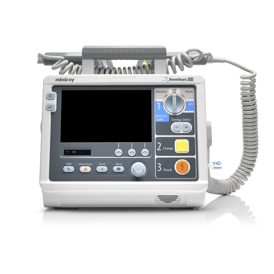
BeneHeart D3
Компактный и легкий дефибриллятор / монитор со встроенными функциями ручной дефибрилляции, автоматической наружной дефибрилляции, кардиостимуляции и мониторинга основных показателей жизнедеятельности. Быстрая зарядка и подача разряда на заданном уровне энергии помогут в проведении эффективной реанимации.
BeneHeart D3 предлагает медицинскому персоналу функцию мониторинга основных показателей жизнедеятельности пациента, включая ЭКГ, дыхание,НИАД и дополнительные данные о концентрации SpO2, позволяя осуществлять непрерывный мониторинг состояния пациента.
Благодаря степени защиты от губительного проникновения пыли и воды IP44, дефибриллятор / монитор D3 обладает надежными рабочими характеристиками и может использоваться в самых разных условиях. В режиме АНД BeneHeart D3 автоматически анализирует частоту сердечных сокращений и определяет целесообразность подачи электрического импульса. Голосовые и текстовые подсказки помогают пользователю в эксплуатации оборудования. Для анализа работы персонала и проверки имеется функция записи речи (180 минут).
Шнур питания
Шнур питания — EU (Европейский)
Состав комплекта
Шнур питания — EU (Европейский)
999
Дефибриллятор-монитор BeneHeart D3 с дисплеем 7 дюймов, о встроенным аккумулятором, термопринтером, функцией мониторинга ЭКГ 3/5 отведений
999
Дефибриллятор-монитор BeneHeart D3 с дисплеем 7 дюймов, со встроенным аккумулятором, термопринтером, функцией мониторинга ЭКГ 3/5 отведений, функцией кардиостимуляции
999
Дефибриллятор-монитор BeneHeart D3 с дисплеем 7 дюймов, со встроенным аккумулятором, термопринтером, функцией мониторинга ЭКГ 3/5 отведений, SpO2, функцией кардиостимуляции
999
Дефибриллятор-монитор BeneHeart D3 с дисплеем 7 дюймов, со встроенным аккумулятором, термопринтером, функцией мониторинга ЭКГ 3/5 отведений, SpO2, НИАД, функцией кардиостимуляции
999
Дефибриллятор-монитор BeneHeart D3 со встроенным аккумулятором, термопринтером, Wi-Fi картой, функцией мониторинга ЭКГ 3/5 отведений, SpO2, НИАД, функцией кардиостимуляции
999
Внешние электроды для дефибрилляции
Набор внешних электродов для дефибрилляции, взр/дет
999
Набор внешних многофункцональных электродов, одноразовый, взр/дет (для пациентов более 25 кг)
999
Набор внешних многофункцональных электродов, одноразовый, дет (для пациентов менее 25 кг)
999
Набор для ЭКГ в составе:
1. Магистральный кабель ЭКГ: 3/5 отведений (взр/дет), с защитой от дефибрилляции
2. Провод ЭКГ на 5 отведений, взрослый, тип защелка 3. ЭКГ электроды: взр, 5 шт, INTCO
999
Набор для ЭКГ в составе:
1. Магистральный кабель ЭКГ: 3/5 отведений (взр/дет), с защитой от дефибрилляции
2. Провод ЭКГ на 3 отведения, взрослый, тип защелка 3. ЭКГ электроды: взр, 5 шт, INTCO
999
Набор для ЭКГ в составе:
1. Магистральный кабель ЭКГ: 3/5 отведений (взр/дет), с защитой от дефибрилляции
2. Провод ЭКГ на 3 отведения, детский, тип защелка
3. ЭКГ электроды:дет, 10 шт, Kendall
999
Набор для ЭКГ в составе:
1. Магистральный кабель ЭКГ: 3/5 отведений (взр/дет)
2. Провод ЭКГ на 5 отведений, взрослый, тип зажим
3. ЭКГ электроды: взр, 5 шт, INTCO
999
Набор для ЭКГ в составе:
1. Магистральный кабель ЭКГ: 3/5 отведений (взр/дет), с защитой от дефибрилляции
2. Провод ЭКГ на 3 отведения, взрослый, тип зажим
3. ЭКГ электроды: взр, 5 шт, INTCO
999
Набор для ЭКГ в составе:
1. Магистральный кабель ЭКГ: 3/5 отведений (взр/дет), с защитой от дефибрилляции
2. Провод ЭКГ на 3 отведения, детский, тип зажим
3. ЭКГ электроды: дет, 10 шт, Kendall
999
Набор для ЭКГ в составе:
1. Магистральный кабель ЭКГ: 3/5 отведений (дет/нео), с защитой от дефибрилляции
2. Провод ЭКГ на 3 отведения, неонатальный, тип зажим 3. ЭКГ электроды: нео, 10 шт, Kendall
999
Набор для Mindray SpO2, в составе: 1. датчик пульсоксиметрический, взрослый, напалечный, 512F (для пациентов более 30 кг) 2. кабель SpO2 (2,5м)
999
Набор для Mindray SpO2, в составе: 1. датчик пульсоксиметрический, детский, напалечный, 512F (для пациентов 10-30 кг) 2. кабель SpO2 (2,5м)
999
Набор для Mindray SpO2, в составе: 1. датчик пульсоксиметрический, для новорожденных (для пациентов <5 кг) 2. кабель SpO2 (2,5м)
999
Набор для Mindray SpO2, в составе: 1. датчик пульсоксиметрический, для взрослых, напалечный DS100A (для пациентов >40 кг) 2. кабель SpO2 (2,5м)
999
Набор для Mindray SpO2, в составе: 1. датчик пульсоксиметрический, для взрослых, напалечный (указательный/большой палец) DS100A (для пациентов 3-40 кг) 2. кабель SpO2 (2,5м)
999
Набор для Mindray SpO2, в составе: 1. датчик пульсоксиметрический, неонатальный OXI-A/N (для пациентов <3кг) 2. кабель SpO2 (2,5м)
999
Набор для НИАД В соответствии с регистрационным удостоверением количество на 1 основную единицу не указано
Набор для НИАД в составе: 1. Трубка для неинвазивного измерения давления 2. Манжета CM1203 , взр (25-35 см)
999
Набор для НИАД в составе: 1. Трубка для неинвазивного измерения давления 2. Манжета CM1202, дет (18-26 см)
999
Набор для НИАД в составе: 1. Трубка для неинвазивного измерения давления 2. Манжета CM1500C, нео, одноразовая (5.8-10.9 см) — 1 шт.
999
Дополнительное отделение сумки для транспортировки
Заднее дополнительное отделение сумки для транспортировки.
Примечание: Крючок на поручень кровати и заднее отделение не могут быть установлены одновременно
999
Сумка для транспортировки
Сумка для транспортировки c защитным покрытием
999
Программное обеспечение на CD
999
Литий-ионный аккумулятор, 15.1 В, 5600 мАч
999
Внешнее зарядное устройство + шнур питания
Внешнее зарядное устройство + шнур питания
999
Кабель п для внешнего зарядного устройства
Кабель постоянного тока для внешнего зарядного устройства, разъем для прикуривателя
999
Крючок на поручень кровати
Крючок на поручень кровати
999
Крепление настольное/транспортное
Крепление настольное/транспортное
999
Панель для крепления внешнего зарядного устройства
Панель для крепления внешнего зарядного устройства
999
Верхнее дополнительное отделение
999
Заднее дополнительное отделение
999
Сумка для D3 c защитным экраном
999
Мультифункциональные электроды
Мультифункциональные электроды для дефибрилляции, взр, одноразовые (1 пара)
999
Мультифункциональные электроды для дефибрилляции, взр, одноразовые (5 пар 115-040517-00 /уп)
999
Мультифункциональные электроды для дефибрилляции, дет, одноразовые (5 пар 115-040518-00/уп)
999
Набор внешних электродов для дефибрилляции, взр/дет
999
Набор внешних электродов для кардиостимуляции, АНД, одноразовый, взр
999
Набор внешних электродов для кардиостимуляции, АНД, одноразовый, дет
999
Датчик SpO2, многоразовый, взр, напалечный, 512F
999
Датчик SpO2, многоразовый, дет, напалечный, мягкий, 512G
999
Датчик SpO2, многоразовый, дет, напалечный, 512H
999
Датчик SpO2, многоразовый, нео, на ногу (Взр/дет, напалечный), 518B
999
Датчик SpO2, для одного пациента, дет, 10 — 50 кг, 520P, 20 шт/уп
999
Датчик SpO2, для одного пациента, дет. мал., 3 — 20 кг, 520I, 20 шт/уп
999
Датчик SpO2, для одного пациента, нео, <3 кг, 520N, 20 шт/уп
999
Кабель для мультифункциональных эелектродов с тестовой нагрузкой (50 Ом)
999
Кабель удлинительный, Mindray SpO2, 7 Pin, 2.5м
999
Кабель Mindray SpO2, 7 Pin, 1.2 м
999
Кабель удлинительный, Nellcor SpO2, 8 Pin
999
Кабель вывода аналогового сигнала
999
Кабель синхронизации с дефибриллятором
999
Тестовая нагрузка (используется с 040-000545-00)
999
Электроды для дефибрилляции на открытом сердце
Электроды для дефибрилляции на открытом сердце, многоразовые, 1 дюйм
999
Электроды для дефибрилляции на открытом сердце, многоразовые, 2 дюйма
999
Электроды для дефибрилляции на открытом сердце, многоразовые, 3 дюйма
999
Кабель ЭКГ с электродами: взр, 5 отведений, Snap, IEC, защита от дефибрилляции
999
Кабель ЭКГ с электродами: взр, 5 отведений, Clip, IEC, защита от дефибрилляции
999
Кабель ЭКГ с электродами: взр/дет, 3 отведения, Snap, IEC, защита от дефибрилляции
999
Кабель ЭКГ с электродами: взр, 3 отведения, Clip, IEC, защита от дефибрилляции
999
Кабель ЭКГ с электродами: дет, 3 отведения, Snap, IEC, защита от дефибрилляции
999
Кабель ЭКГ с электродами: дет, 3 отведения, Clip, IEC, защита от дефибрилляции
999
Кабель ЭКГ с электродами: нео, 3 отведения, Clip, IEC, защита от дефибрилляции
999
Датчик SpO2, многоразовый, дет/мал. дет, OXI-P/I
999
Датчик SpO2, многоразовый, взр/нео, с 50 фиксаторами
999
Датчик SpO2, взр/дет/нео/мал. дет., Dura-Y Multi-Site
999
Датчик SpO2, одноразовый, взр, >30kg, MAX-A, 24 шт/уп
999
Датчик SpO2, одноразовый, дет, 10 — 50 кг, MAX-P , 24 шт/уп
999
Датчик SpO2, одноразовый, дет. мал., 3 — 20 кг, MAX-I , 24 шт/уп
999
Датчик SpO2, одноразовый, взр/нео, >40 кг или <3 кг, MAX-N , 24 шт/уп
999
ЭКГ электроды: взр, 10 шт/уп, Kendall
999
ЭКГ электроды: нео, 50 шт/уп, Coviden
999
Магистральный кабель ЭКГ: 3 отведения, нео, 12 Pin, TPU, AHA/IEC, DIN
999
Магистральный кабель ЭКГ: 3/5 отведений, взр/дет, 12 Pin, защита от дефибрилляции, AHA/IEC
999
Магистральный кабель ЭКГ: 3 отведения, дет/нео, 12 Pin, защита от дефибрилляции, AHA/IEC
999
3-отведения ЭКГ, кнопка, взр/дет, 1 м
999
3-отведения ЭКГ, зажим, взр/дет, 1 м
999
3-отведения ЭКГ, зажим, нео, 1 м
999
5-отведений ЭКГ, кнопка, взр/дет, 1 м/1.4 м
999
5-отведений ЭКГ, зажим, взр/дет (длинный, 1 м/1.4 м)
999
5-отведений ЭКГ, зажим, взр/дет, 0,6 м/1 м
999
Датчик SpO2, многоразовый, взр, напалечный, мягкий, 512E
999
Датчик SpO2, для одного пациента, взр, >30кг, 520A, 20 шт/уп
999
Датчик SpO2, многоразовый, взр, DS-100A
999
Фиксаторы для датчика SpO2, 518C (12шт/уп)
999
Трубка + манжета, взр (25-35 см)
999
Трубка + манжета, взр (25-35 см)
999
Трубка + манжета, дет (18-26 см)
999
Трубка + манжета, дет (18-26 см)
999
Трубка + манжета, нео, одноразовая (5.8-10.9 см)
999
Трубка для НИАД, взр/дет/мал.дет., 3 м
999
Трубка для НИАД, нео, 3 м
999
Манжета многоразовая, мал. дет., с коннектором, 7-13 см
999
Манжета многоразовая, мал. дет., с коннектором, 10-19 см, CM1201
999
Манжета многоразовая, дет, с коннектором, 18-26 см, CM1202
999
Манжета многоразовая, взр, с коннектором, 25-35 см, CM1203
999
Манжета многоразовая, бол. взр, с коннектором, 33-47 см, CM1204
999
Манжета многоразовая, набедренная, с коннектором, 46-66 см, CM1205
999
Манжета многоразовая, дет, бескамерная, с коннектором, 18-26 см, CM1302
999
Манжета многоразовая, взр, бескамерная, с коннектором, 25-35 см, CM1303
999
Манжета многоразовая, бол.взр, бескамерная, с коннектором, 33-47 см, CM1304
999
Манжета многоразовая, набедренная, бескамерная, с коннектором, 46-66 см, CM1305
999
Манжета многоразовая, взр, длинная, бескамерная, с коннектором, 25-35 см, CM1306
999
Манжета многоразовая, бол. взр, длинная, бескамерная, с коннектором, 33-47 см, CM1307
999
Манжета одноразовая, дет, 18-26 см, CM1502, 10 шт/уп
999
Манжета одноразовая, взр, 25-35 см, CM1503, 10 шт/уп
999
Манжета одноразовая, набедренная, 46-66 см, CM1505, 10 шт/уп
999
Манжета одноразовая, длинная взр, бескамерная, 25-35 см, CM1506, 10 шт/уп
999
Манжета одноразовая, длинная взр, бескамерная, 33-47 см, CM1507, 10 шт/уп
999
Манжета одноразовая, нео, 3.1-5.7 см, CM1500A, 20 шт/уп
999
Манжета одноразовая, нео, 4.3-8.0 см, CM1500B, 20 шт/уп
999
Манжета одноразовая, нео, 5.8-10.9 см, CM1500C, 20 шт/уп
999
Манжета одноразовая, нео, 7.1-13.1 см, CM1500D, 20 шт/уп
999
Манжета одноразовая, нео, 8-15 см, CM1500Е, 20 шт/уп
999
Термобумага (50 мм х 20 м)
999
Адаптер для постоянного/переменного тока
Адаптер постоянного/переменного тока (DC/AC)
999
Оставить отзыв
У данного товара нет отзывов. Станьте первым, кто оставил отзыв об этом товаре!
Intellectual Property Statement
SHENZHEN MINDRAY BIO-MEDICAL ELECTRONICS CO., LTD. (hereinafter called Mindray) owns the intellectual property
rights to this Mindray product and this manual. This manual may refer to information protected by copyright or
patents and does not convey any license under the patent rights or copyright of Mindray, or of others.
Mindray intends to maintain the contents of this manual as confidential information. Disclosure of the information in
this manual in any manner whatsoever without the written permission of Mindray is strictly forbidden.
Release, amendment, reproduction, distribution, rental, adaptation, translation or any other derivative work of this
manual in any manner whatsoever without the written permission of Mindray is strictly forbidden.
,
,
and
are the trademarks, registered or otherwise, of
Mindray in China and other countries. All other trademarks that appear in this manual are used only for informational
or editorial purposes. They are the property of their respective owners.
II
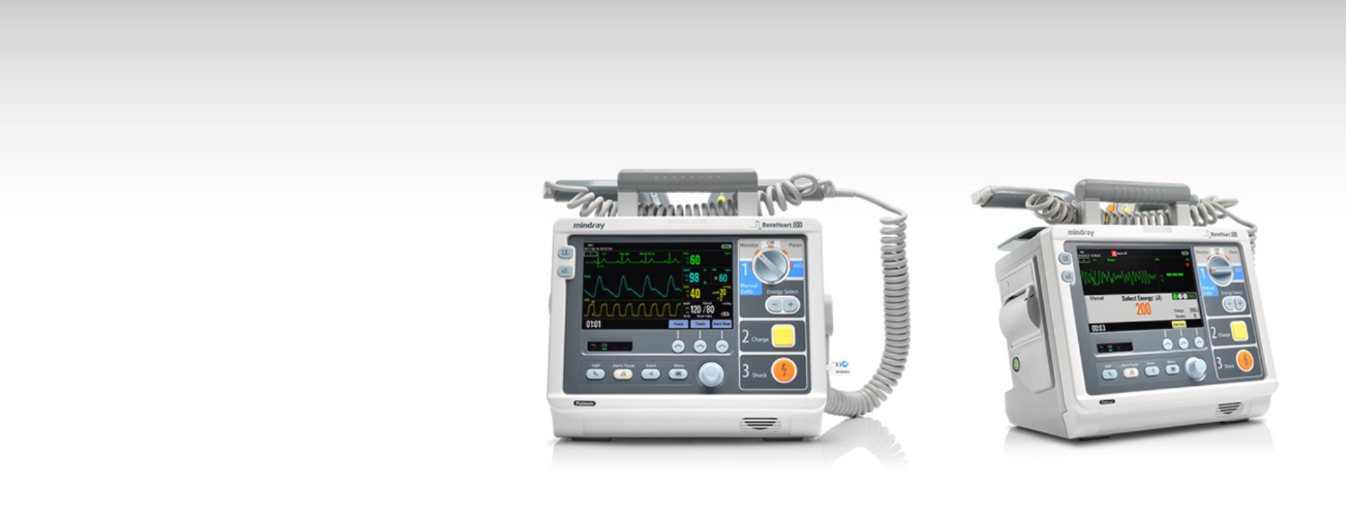
BeneHeart D3 — это компактный, надежный и легкий дефибриллятор со встроенными функциями мониторинга, ручной дефибрилляции, автоматической наружной дефибрилляции и кардиостимуляции. Этот профессиональный бифазный дефибриллятор-монитор подходит для использования в медицинских учреждениях во всем мире.
Характеристики
Быстрое проведение реанимационных мероприятий
· Включение питания за 2 секунды
· Зарядка до 200 Дж за 3 секунды
· Восстановление ЭКГ всего за 2,5 секунды
Технология 360 Дж BTe
В дефибрилляторах BeneHeart D3 используется двухфазная технология 360 Дж с автоматической компенсацией импеданса, что повышает шансы на спасение пациентов со сложными случаями дефибрилляции.
Простота в использовании
Следуя интуитивно понятным последовательным шагам (1) выбор уровня мощности; 2) заряд; 3) разряд), врач может проводить простую ручную дефибрилляцию, не отвлекаясь от пациента и не теряя драгоценное время.
Постоянная готовность в режиме ожидания
Благодаря ежедневной и еженедельной самодиагностике с автоматической загрузкой отчетов о результатах на центральную станцию дефибриллятор BeneHeart D3 может применяться для спасения жизни в любой момент. Надежный аккумулятор, выдерживающий 200 разрядов при 360 Дж и 6 часов непрерывного мониторинга, также гарантирует работоспособность устройства.
Эффективное ИТ-решение
Наше эффективное ИТ-решение позволяет управлять всей информацией с BeneHeart D3 и передавать ее в мощную систему централизованного мониторинга через WiFi 5G/2.4G. Совместимо с международным стандартным протоколом IHE HL7 и DHCP.
* Mindray предоставляет 2 варианта измерения SpO2: с помощью аппаратов Mindray, и Nellcor. Для получения информации о наличии измерителей SpO2 Masimo и Nellcor свяжитесь с местными торговыми представителями.
Комплектация
Профили конфигурации можно легко настроить и загрузить для различных клинических сценариев или эксплуатационных требований, включая значения по умолчанию, структуру экрана и конфигурацию системы.
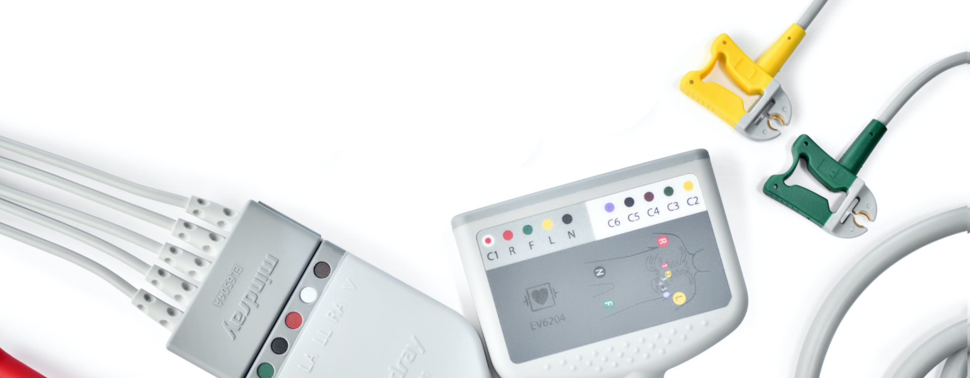
- Способ управления: ручной, автоматический
- Импульс дефибрилляции: усеченный экспоненциальный бифазный
- Режим работы: асинхронная внешняя дефибрилляция
- Число разрядов: 100 (360 Дж)
- Каналы для измерения: ЭКГ
- Для новорожденных, детей и взрослых
- Регистрационное удостоверение
Арт. 6591
Дефибриллятор-монитор Mindray BeneHeart D3
- Описание
- Характеристики
- Комплектация
- Данные для транспортировки
- Документация
- Дефибриллятор-монитор Mindray BeneHeart D3 компактная и легкая конструкция «четыре в одном» объединяет функции мониторинга, ручной дефибрилляции, автоматической наружной дефибрилляции и кардиостимуляции
- Подходит для применения в медицинских учреждениях, а также для условий вне стационара
- Большой и яркий дисплей обеспечивает отображение 3 кривых и позволяет просматривать кривые ЭКГ
- Дефибрилляция, синхронизированная кардиоверсия и автоматическая наружная дефибрилляция используют бифазную технологию
- Возможность подачи разряда энергией до 360 Дж обеспечивает максимальную вероятность успешной дефибрилляции
- Мощная аккумуляторная батарея поддерживает длительный непрерывный мониторинг и подачу разрядов во время транспортировки пациента без использования внешних источников питания
Перед применением необходимо ознакомиться с инструкцией по применению (паспортом изделия) или получить консультацию специалиста
Способ управления
ручной, автоматический
Импульс дефибрилляции
усеченный экспоненциальный бифазный
Режим работы
асинхронная внешняя дефибрилляция
Уровни энергии, Дж
1–10, 15, 20, 30, 50, 70, 100, 150, 170, 200, 300, 360 — ручной режим, 100–360 — режим АНД
Число разрядов
100 (360 Дж) с интервалом в 1 мин
Разрешение, пиксели
800х480
Время от начала анализа до завершения набора энергии, не более, с
20
Электроды
взрослые/детские, многоразовые
Время заряда батареи, не более, ч
3 — при выключенном устройстве, 4,5 — при включенном
Работа от встроенной батареи, ч
2,5 — мониторинг, 100 разрядов по 360 Дж с интервалом в 1 мин — дефибрилляция
Электропитание от сети переменного тока, В/Гц
220/50
Электропитание от встроенной батареи, В
14,8
Электробезопасность
класс I, тип BF
Гарантия производителя, мес.
12
Дефибриллятор-монитор Mindray BeneHeart D3
Перед применением необходимо ознакомиться с инструкцией по применению (паспортом изделия) или получить консультацию специалиста
- Дефибриллятор-монитор — 1 шт.
- Кабель ЭКГ с электродами — 1 шт.
- Комплект электродов внешних (взрослые/детские) — 1 шт.
- Аккумулятор многоразовый — 1 шт.
- Гель 250 гр. — 1 шт.
- Рулонная бумага для термопринтера — 3 шт.
- Руководство по эксплуатации
Габариты в упаковке, м
0,550х0,410х0,375
Количество изделий в упаковке
1
Упаковка
картонная коробка
Дополнительная упаковка
требуется