- Manuals
- Brands
- DENTSPLY Manuals
- Dental equipment
- X-SMART Endo Motor
- Operation manual
-
Contents
-
Table of Contents
-
Troubleshooting
-
Bookmarks
Quick Links
Related Manuals for DENTSPLY X-SMART Endo Motor
Summary of Contents for DENTSPLY X-SMART Endo Motor
-
Page 2: Table Of Contents
Introduction — Indications — Contraindications — Warnings — Precautions — Notice — Adverse reactions A> Contents B> Product Main Specifications C> Product Description D> How to connect each part E> Main Directions For Use F> Additional Directions For Use G> Cleaning H>…
-
Page 3
(such as electric shavers, hair dryers, etc.) it is recommended that the X-SMART Endo Motor not be used. This motor should not be used for severe curved root canal preparation. Do not use the X-SMART Endo Motor for implant or any other dentist procedure outside endodontics. Warnings those that DENTSPLY Tulsa Dental Specialties specifies. -
Page 4: Notice
Precautions The RPM number indicates true instrument speed when the appropriate reduction rate is selected. Make sure the selected reduction matches the ratio of the contra-angle handpiece. If the motor stops or runs too fast, discontinue use and call for assistance. before use.
-
Page 5: Adverse Reactions
Recharge batteries after they discharge as much as possible. Repeated shorttime use and subsequent recharging may shorten their operating complete discharge and full charge for a few times. (This product is equipped The used nickel metal hydride batteries are recyclable, but their disposal may sometimes not be permitted by local regulations.
-
Page 6: B> Product Main Specifications
A> Contents Before use, please refer to the packaging labels. B> Product Main Specifications X-SMART Endo Motor control unit Rated input Output Dimensions Weight X-SMART Rated input Dimensions Weight X-SMART Endo Motor handpiece Rated input Dimensions Weight (including motor handpiece cord)
-
Page 7: C> Product Description
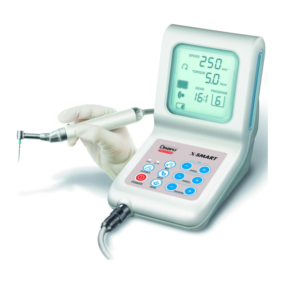
C> Product Description 1) Control Unit 2) Operation Panel 3) LCD Panel 4) Power Cord Connector 5) Foot Pedal Connector 6) Motor Handpiece Connector 7) AC Adapter
 Motor Handpiece 9) Contra-Angle 10) Handpiece Stand 11) F-type Spray Nozzle (used for lubrication) 12) Foot pedal (Option)
 -
Page 8
* Operation Panel and LCD Panel. The rotation speed can be adjusted. alarm sounds. present rotation speed displayed. The unit is is displayed depending on the X100 rotation speed. The torque limit values can be adjusted. sounds. the instrument manufacturer for suggested ranges. -
Page 9
The present torque limit value is displayed. The unit is (Ncm). The Program button is also used to manage the alarm sound. The rotational direction of the file can be changed by this key. It can also be changed while the file is in motion. The alarm sounds during reverse rotation. -
Page 10
The present auto reverse mode mark is displayed. If the load is removed after auto reverse rotation, it returns to the normal rotation again. If the load is removed after auto reverse rotations, it stops. (Non display) Press this key if you want to change the present program setting (rotation speed, torque limit value, gear ratio, auto reverse mode) and these changes will be OFF position of the power. -
Page 11
Full charge Less tha batteries. NOTICE The remaining amount of batteries mark indicates a voltage. When load is ap- plied to the motor handpiece, the remaining amount of batteries mark appears to become lower. ON or OFF position of the power. It displays the bar graph which shows the degree of load applied to the motor while the file is in motion. -
Page 12: D> How To Connect Each Part
D> How to connect each part (1) Connecting Motor Handpiece mark of the cord plug of the motor handpiece with the mark of the motor handpiece connector and insert Fig. 3 NOTICE To remove the plug, hold the plug ring and pull it out. (2) Connecting AC Adapter into the power connector with the Fig.
-
Page 13: E> Main Directions For Use
E> Main Directions For Use Fig. 6 (1) Charge (if batteries are used) CAUTION will occur. Since the AC IN lamp lights to indicate that the supply power is on, it does not charging conditions. The standard charging time is about 5 hours, but it varies depending on use, condition of batteries, temperature and whether the batteries are new or old.
-
Page 14
Therefore, if this product is placed in an environment where the temperature changes rapidly (for example, near to a window exposed to sunlight, near the outlet of an airconditioner, or heater), the battery cannot be properly charged. Put this product in a place where the temperature varies little. fully charged). -
Page 15
The file rotates in reverse. When a load is removed, the file returns to normal rotation (forward rotation) automatically. Fig. 8 AUTO STOP The motor handpiece starts in reverse. When a load is removed, the motor handpiece stops. If you want it to rotate (forward-rotate) again, re-press the ON/OFF button or re-step on the foot pedal (Optional). -
Page 16
1. Insert the file into the chuck until it stops. Lightly turn the file until it engages with the latch mechanism. Push inwards to click. File Removal: Depress the push-button and pull Fig. 10 out the file. CAUTION locked. chuck could cause loss of concentricity and deterioration of chucking force. (4) Preparatory Operations used. -
Page 17
(5) Operation motor handpiece starts. If you re-press the button, it stops. If you hold down the ON/OFF button for more than one second, the motor handpiece starts while the button is pressed. If you release the button, it stops. If the foot pedal (Optional) is connected, Fig. -
Page 18
NOTICE When the batteries go down (when the remaining amount of the batteries value. In this case (in the case of operation by batteries), this auto reverse function will not be activated. When high torque is required, use the AC adapter or use this product in a condition where the batteries are not signifi- cantly consumed (when the mark of the remaining amount of the batteries If a load is continuously applied to the motor handpiece, it may automatically… -
Page 19: F> Additional Directions For Use
F> Additional Directions For Use (1) Program files to be used. You can change any preset values and have them saved to your desired settings (rotation speed, torque limit value, gear ratio and auto reverse mode). mode by each key according to your needs. NOTICE The program cannot be memorized while the motor handpiece is in motion.
-
Page 20
NOTICE This function is not activated unless this product is powered by the AC adapter. Nickel metal hydrate batteries may result in a decrease in charging capacity, if additional charging (repeating a cycle of short-time use and recharging) is made. function is used to resolve this phenomenon. -
Page 21
(4) Calibration and the difference in torque by the contra-angle. original state. NOTICE obstructs. motor handpiece and contra-angle. sound volume at the time of confirmation and error, while it does not sound at the time of reverse rotation and attainment of the torque limit value. and the required sound level is set up. -
Page 22: G> Cleaning
G> Cleaning (1) Lubricating Contra-Angle autoclaving. of the contra-angle head and lubricate Fig. 12 (2) Cleaning Motor Handpiece When the motor handpiece becomes dirty, wipe off with a cotton cloth moistened with rubbing alcohol. (3) Cleaning Control Unit When the control unit becomes dirty, wipe it off with a cotton cloth moistened with rubbing alcohol.
-
Page 23: H> Sterilization
H> Sterilization 1. Brush the dirt off the surface of the contra-angle head, and wipe off with a cotton cloth moistened with rubbing alcohol. Do not use a metal brush. CAUTION sterilization to any part other than the contra-angle head. place the head on the central or upper tray.
-
Page 24: I> Changing Batteries
I> Changing batteries X-SMART Endo Motor uses rechargeable batteries. They can be recharged operating time or recharging time becomes shorter or the rotation power becomes applicable, the life of the batteries is suspect. In such a case, replace batteries (refer to the shall not be held liable for any malfunction or failure resulting from not following of batteries and moisture infiltrating this product.
-
Page 25
CAUTION Ensure you pull out the cord by holding the connector. Failure to do so may cause a break in the cord. accordance with the polarity indication label inside the battery chamber, and place the batteries into the chamber with care so as not to catch the cord. CAUTION In case of difficulty inserting the connector onto the battery, the polarity may be incorrect. -
Page 26: J> Error Code
J> Error Code If the motor handpiece stops due to an abnormality such as a malfunction, overload, breakage or misuse, it automatically checks the state of the control unit panel. If an error code is displayed, turn on the power again and check whether the same error code is displayed.
-
Page 27
Below the lower limit tion expired. Other Abnormal heat The batteries generate generation from If the heat generates from abnormal heat. the new set of batteries, batteries malfunction of the circuit may be suspected. Contact Dentsply Tulsa Dental Specialties. -
Page 28: K> Troubleshooting
K> Troubleshooting When trouble is found, check the following again before contacting DENTSPLY Tulsa Dental Specialties. If none of these are applicable or the trouble is not rem- X-SMART Problem Cause The power is not turned on. The AC adapter is not Check the connection.
-
Page 29
Problem Cause The battery charger does No batteries are inserted. Insert batteries. not work. The batteries are fully charged No problem. not light.) or in a state near full charge. The temperature of batteries If the temperature of batteries is less is low. -
Page 30
X-SMART Endo Motor handpiece Problem Cause The motor handpiece The motor handpiece cord is not Check the connection. does not rotate. connected. The foot pedal (Optional) is not Check the connection. connected. There is a break in the motor handpiece Contact your Technical Service or the motor handpiece cord. -
Page 31: L> Warranty
Manufacturers warrant the product to the original purchaser against defects in material and workmanship under normal practices of installation, use and servicing. The X-SMART Endo Motor control unit, motor and contra-angle are guaranteed for The accessories (battery, stand) are not covered under the warranty.
-
Page 32
Manufactured for: For Dental Use Only Rx Only Made in Japan Consult Instructions For Use © 2012 DENTSPLY International, Inc. DFUXSMART Rev. 4 6/12…
 Motor Handpiece 9) Contra-Angle 10) Handpiece Stand 11) F-type Spray Nozzle (used for lubrication) 12) Foot pedal (Option)
 Перейти к контенту
- Manuals
- Brands
- DENTSPLY Manuals
- Dental equipment
- X-SMART Endo Motor
- Operation manual
-
Contents
-
Table of Contents
-
Troubleshooting
-
Bookmarks
Quick Links
Related Manuals for DENTSPLY X-SMART Endo Motor
Summary of Contents for DENTSPLY X-SMART Endo Motor
-
Page 2: Table Of Contents
Introduction — Indications — Contraindications — Warnings — Precautions — Notice — Adverse reactions A> Contents B> Product Main Specifications C> Product Description D> How to connect each part E> Main Directions For Use F> Additional Directions For Use G> Cleaning H>…
- Page 3
(such as electric shavers, hair dryers, etc.) it is recommended that the X-SMART Endo Motor not be used. This motor should not be used for severe curved root canal preparation. Do not use the X-SMART Endo Motor for implant or any other dentist procedure outside endodontics. Warnings those that DENTSPLY Tulsa Dental Specialties specifies. -
Page 4: Notice
Precautions The RPM number indicates true instrument speed when the appropriate reduction rate is selected. Make sure the selected reduction matches the ratio of the contra-angle handpiece. If the motor stops or runs too fast, discontinue use and call for assistance. before use.
-
Page 5: Adverse Reactions
Recharge batteries after they discharge as much as possible. Repeated shorttime use and subsequent recharging may shorten their operating complete discharge and full charge for a few times. (This product is equipped The used nickel metal hydride batteries are recyclable, but their disposal may sometimes not be permitted by local regulations.
-
Page 6: B> Product Main Specifications
A> Contents Before use, please refer to the packaging labels. B> Product Main Specifications X-SMART Endo Motor control unit Rated input Output Dimensions Weight X-SMART Rated input Dimensions Weight X-SMART Endo Motor handpiece Rated input Dimensions Weight (including motor handpiece cord)
-
Page 7: C> Product Description
C> Product Description 1) Control Unit 2) Operation Panel 3) LCD Panel 4) Power Cord Connector 5) Foot Pedal Connector 6) Motor Handpiece Connector 7) AC Adapter
Motor Handpiece 9) Contra-Angle 10) Handpiece Stand 11) F-type Spray Nozzle (used for lubrication) 12) Foot pedal (Option)
- Page 8
* Operation Panel and LCD Panel. The rotation speed can be adjusted. alarm sounds. present rotation speed displayed. The unit is is displayed depending on the X100 rotation speed. The torque limit values can be adjusted. sounds. the instrument manufacturer for suggested ranges. - Page 9
The present torque limit value is displayed. The unit is (Ncm). The Program button is also used to manage the alarm sound. The rotational direction of the file can be changed by this key. It can also be changed while the file is in motion. The alarm sounds during reverse rotation. - Page 10
The present auto reverse mode mark is displayed. If the load is removed after auto reverse rotation, it returns to the normal rotation again. If the load is removed after auto reverse rotations, it stops. (Non display) Press this key if you want to change the present program setting (rotation speed, torque limit value, gear ratio, auto reverse mode) and these changes will be OFF position of the power. - Page 11
Full charge Less tha batteries. NOTICE The remaining amount of batteries mark indicates a voltage. When load is ap- plied to the motor handpiece, the remaining amount of batteries mark appears to become lower. ON or OFF position of the power. It displays the bar graph which shows the degree of load applied to the motor while the file is in motion. -
Page 12: D> How To Connect Each Part
D> How to connect each part (1) Connecting Motor Handpiece mark of the cord plug of the motor handpiece with the mark of the motor handpiece connector and insert Fig. 3 NOTICE To remove the plug, hold the plug ring and pull it out. (2) Connecting AC Adapter into the power connector with the Fig.
-
Page 13: E> Main Directions For Use
E> Main Directions For Use Fig. 6 (1) Charge (if batteries are used) CAUTION will occur. Since the AC IN lamp lights to indicate that the supply power is on, it does not charging conditions. The standard charging time is about 5 hours, but it varies depending on use, condition of batteries, temperature and whether the batteries are new or old.
- Page 14
Therefore, if this product is placed in an environment where the temperature changes rapidly (for example, near to a window exposed to sunlight, near the outlet of an airconditioner, or heater), the battery cannot be properly charged. Put this product in a place where the temperature varies little. fully charged). - Page 15
The file rotates in reverse. When a load is removed, the file returns to normal rotation (forward rotation) automatically. Fig. 8 AUTO STOP The motor handpiece starts in reverse. When a load is removed, the motor handpiece stops. If you want it to rotate (forward-rotate) again, re-press the ON/OFF button or re-step on the foot pedal (Optional). - Page 16
1. Insert the file into the chuck until it stops. Lightly turn the file until it engages with the latch mechanism. Push inwards to click. File Removal: Depress the push-button and pull Fig. 10 out the file. CAUTION locked. chuck could cause loss of concentricity and deterioration of chucking force. (4) Preparatory Operations used. - Page 17
(5) Operation motor handpiece starts. If you re-press the button, it stops. If you hold down the ON/OFF button for more than one second, the motor handpiece starts while the button is pressed. If you release the button, it stops. If the foot pedal (Optional) is connected, Fig. - Page 18
NOTICE When the batteries go down (when the remaining amount of the batteries value. In this case (in the case of operation by batteries), this auto reverse function will not be activated. When high torque is required, use the AC adapter or use this product in a condition where the batteries are not signifi- cantly consumed (when the mark of the remaining amount of the batteries If a load is continuously applied to the motor handpiece, it may automatically… -
Page 19: F> Additional Directions For Use
F> Additional Directions For Use (1) Program files to be used. You can change any preset values and have them saved to your desired settings (rotation speed, torque limit value, gear ratio and auto reverse mode). mode by each key according to your needs. NOTICE The program cannot be memorized while the motor handpiece is in motion.
- Page 20
NOTICE This function is not activated unless this product is powered by the AC adapter. Nickel metal hydrate batteries may result in a decrease in charging capacity, if additional charging (repeating a cycle of short-time use and recharging) is made. function is used to resolve this phenomenon. - Page 21
(4) Calibration and the difference in torque by the contra-angle. original state. NOTICE obstructs. motor handpiece and contra-angle. sound volume at the time of confirmation and error, while it does not sound at the time of reverse rotation and attainment of the torque limit value. and the required sound level is set up. -
Page 22: G> Cleaning
G> Cleaning (1) Lubricating Contra-Angle autoclaving. of the contra-angle head and lubricate Fig. 12 (2) Cleaning Motor Handpiece When the motor handpiece becomes dirty, wipe off with a cotton cloth moistened with rubbing alcohol. (3) Cleaning Control Unit When the control unit becomes dirty, wipe it off with a cotton cloth moistened with rubbing alcohol.
-
Page 23: H> Sterilization
H> Sterilization 1. Brush the dirt off the surface of the contra-angle head, and wipe off with a cotton cloth moistened with rubbing alcohol. Do not use a metal brush. CAUTION sterilization to any part other than the contra-angle head. place the head on the central or upper tray.
-
Page 24: I> Changing Batteries
I> Changing batteries X-SMART Endo Motor uses rechargeable batteries. They can be recharged operating time or recharging time becomes shorter or the rotation power becomes applicable, the life of the batteries is suspect. In such a case, replace batteries (refer to the shall not be held liable for any malfunction or failure resulting from not following of batteries and moisture infiltrating this product.
- Page 25
CAUTION Ensure you pull out the cord by holding the connector. Failure to do so may cause a break in the cord. accordance with the polarity indication label inside the battery chamber, and place the batteries into the chamber with care so as not to catch the cord. CAUTION In case of difficulty inserting the connector onto the battery, the polarity may be incorrect. -
Page 26: J> Error Code
J> Error Code If the motor handpiece stops due to an abnormality such as a malfunction, overload, breakage or misuse, it automatically checks the state of the control unit panel. If an error code is displayed, turn on the power again and check whether the same error code is displayed.
- Page 27
Below the lower limit tion expired. Other Abnormal heat The batteries generate generation from If the heat generates from abnormal heat. the new set of batteries, batteries malfunction of the circuit may be suspected. Contact Dentsply Tulsa Dental Specialties. -
Page 28: K> Troubleshooting
K> Troubleshooting When trouble is found, check the following again before contacting DENTSPLY Tulsa Dental Specialties. If none of these are applicable or the trouble is not rem- X-SMART Problem Cause The power is not turned on. The AC adapter is not Check the connection.
- Page 29
Problem Cause The battery charger does No batteries are inserted. Insert batteries. not work. The batteries are fully charged No problem. not light.) or in a state near full charge. The temperature of batteries If the temperature of batteries is less is low. - Page 30
X-SMART Endo Motor handpiece Problem Cause The motor handpiece The motor handpiece cord is not Check the connection. does not rotate. connected. The foot pedal (Optional) is not Check the connection. connected. There is a break in the motor handpiece Contact your Technical Service or the motor handpiece cord. -
Page 31: L> Warranty
Manufacturers warrant the product to the original purchaser against defects in material and workmanship under normal practices of installation, use and servicing. The X-SMART Endo Motor control unit, motor and contra-angle are guaranteed for The accessories (battery, stand) are not covered under the warranty.
- Page 32
Manufactured for: For Dental Use Only Rx Only Made in Japan Consult Instructions For Use © 2012 DENTSPLY International, Inc. DFUXSMART Rev. 4 6/12…
Быстро доставляем по всей России:
Москва,
Санкт-Петербург,
Новосибирск,
Екатеринбург,
Нижний Новгород,
Казань,
Челябинск,
Омск,
Самара,
Ростов-на-Дону,
Уфа,
Красноярск,
Воронеж,
Пермь,
Волгоград,
Краснодар,
Саратов,
Тюмень,
Тольятти,
Ижевск,
Барнаул,
Ульяновск,
Иркутск,
Хабаровск,
Ярославль,
Владивосток,
Махачкала,
Томск,
Оренбург,
Кемерово,
Новокузнецк,
Рязань,
Астрахань,
Набережные Челны,
Пенза,
Киров,
Липецк,
Чебоксары,
Калининград,
Тула,
Курск,
Севастополь,
Сочи,
Ставрополь,
Улан-Удэ,
Магнитогорск,
Белгород,
Сургут,
Нижний Тагил,
Чита,
Архангельск,
Симферополь,
Якутск,
Мурманск,
Комсомольск-на-Амуре,
Сыктывкар,
Норильск и ещё более 1060 городов:
Пункты самовывоза
© 2008 — 2023 Copyright MirDental.RU | Время работы: По будням с 9:00 до 18:00
|
Товарные предложения, представленные на сайте, не являются публичной офертой, определяемой положениями ст. 437 (2) ГК РФ.

-15%
![]()
-15%

Код товара: —
Страна производства
Швейцария
![]()
1 год гарантии
Описание
X-Smart Plus (Икс-Смарт Плюс) — это простой и удобный в использовании мотор (эндодонтический наконечник), созданный для врачей-стоматологов.
Мотор отличает компактность и эргономичность. Легкая рукоятка наконечника с миниатюрной головкой, отсутствие напольной педали и возможность работы от аккумулятора позволяют чувствовать себя более комфортно при выполнении операции и полностью сконцентрировать свое внимание на пациенте.
Мотор обладает реципрокным движением, помимо ротационного, а также контролем торка и режимом авто-реверса.
Преимущества:
- Отсутствует напольная педаль
- Кнопка вкл./выкл. находится на рукоятке наконечника
- Отличный обзор и доступ к полости
- Благодаря миниатюрной головке углового наконечника
- Удобный интерфейс
- Крупный экран
- Интуитивное управление
- Эргономичный дизайн
- Цветной дисплей в кодировке ISO
- Один никель-титановый инструмент для обработки корневого канала
- Реципрокное движение мотора
- Удобное управление режимами
- «Архив» роторных и реципрокных инструментов Dentsply (WaveOne™, ProTaper® Universal, PathFile™, Gates и Reciproc™ и 8 свободных программ)
Технические характеристики:
- Скорость вращения от 250 до 1200 об/мин
- Регулировка крутящего момента в интервале 0,6 — 4,0 Нсм.
- Угловой наконечник со съемной редукционной головкой, понижение 6:1.
- Кнопочная фиксация файла.
- Для удобства в работе головка может фиксироваться в 6-ти различных положениях.
- Наконечник и головка могут автоклавироваться при температуре 134°C.
- Работает на аккумуляторе или через сеть.
- Полная зарядка аккумулятора за 5 часов.
- Около 2-х часов безостановочной работы без подзарядки.
- Габаритные размеры (ш х в х г) 107х196х107 мм
- Вес 600 г
Характеристики
Страна производства
Швейцария
Технические характеристики
Встроенный апекслокатор
Нет
Эндомотор X-Smart Plus в базовой комплектации
87 290₽
/шт
102 700₽
Экономия 15 410₽
Добавить к сравнению
USER MANUAL
Electronic instructions for use
For additional languages, visit our website: www.dentsplymaillefer.com
Technical modifications on our products are not subject to notification. Photos on our devices are not contractual.
FISDR-JAP / F1902124.EN / 07 / 2011 – updated 10/2016
— 2 / 47 —
USER MANUAL
Table of Contents
Introduction
1. Indications for Use
2. Contraindications
3. Warnings
4. Precautions
5. Adverse Reactions
6. Step-by-Step Instructions
6.1.
Standard Components
6.2.
Operation Panel
6.3.
LCD Panel
6.4.
Preparation
6.5.
Installation
6.5.1.
Connecting the AC adapter
6.5.2.
Connecting and Disconnecting the Motor Handpiece
6.5.3.
Connecting and Disconnecting the Contra-angle
6.5.4.
Inserting and Removing the File
6.5.5.
Charging the Battery
6.5.6.
Calibration
6.5.7.
Sound Volume Adjustment
6.6.
Operation
6.6.1.
File Library
6.6.2.
Switch-on and Switch off the Unit
6.6.3.
Switch-on and Switch off the Motor Handpiece
6.6.4.
Auto Reverse Function
6.7.
Selecting a File System
6.7.1.
Continuous Rotary File Systems
6.7.2.
Reciprocating File Systems
6.7.3.
“Program” for Continuous Rotary File Systems
6.7.4.
Changing Torque and Speed
6.8.
Factory Default Parameters
6.9.
Battery Refresh
6.10.
Displaying the Software Version
6.11.
Maintenance
6.11.1.
Changing the Battery
6.11.2.
Lubricating the Contra-angle
6.12.
Cleaning, Disinfection and Sterilization
6.12.1.
Foreword
6.12.2.
General Recommendations
6.12.3.
Step-by-Step Procedure
FISDR-JAP / F1902124.EN / 07 / 2011 – updated 10/2016
26
26
28
29
24
24
25
21
22
22
23
19
20
21
21
32
32
32
33
29
30
30
31
16
17
18
18
12
14
16
16
1
0
11
8
9
6
6
5
6
— 3 / 47 —
7. Technical Specifications
7.1.
Classifications of Equipment
7.2.
Product Main Specifications
8. Error Code
9. Troubleshooting
10. Warranty
11. Disposal of the Product
12. Identification of Symbols
13. Program – Individual Continuous Rotary Program
APPENDIX
Electromagnetic Emissions and Immunity
39
40
41
41
42
34
34
34
36
43
FISDR-JAP / F1902124.EN / 07 / 2011 – updated 10/2016
— 4 / 47 —
FOR DENTAL USE ONLY
Introduction
Congratulations on your purchase of the X-SMART
®
Plus endo motor.
Read this User Manual carefully before use for operating instructions, care and maintenance.
Keep this manual for future reference.
FISDR-JAP / F1902124.EN / 07 / 2011 – updated 10/2016
— 5 / 47 —
1.
Indications for use
The X-SMART
®
Plus endo motor is a medical device according to the Medical Device Directive
93/42/EEC, designed for use by dentists for driving dental root canal instruments in continuous rotation and in reciprocating movement.
This device must only be used in hospital environments, clinics or dental offices by qualified dental personnel.
2.
Contraindications
In cases where a patient has been fitted with an implanted heart pacemaker (or other electrical equipment) and has been cautioned against the use of small electrical appliances
(such as electric shavers, hair dryers, etc.) it is recommended not to use the X-SMART
Plus.
X-SMART Plus should not be used for severely curved root canal preparation.
Do not use X-SMART Plus for implant or any other dentist procedure outside endodontics.
3.
Warnings
In this chapter, a description of serious adverse reactions and potential safety hazards for the product or the user/patient is included.
Read the following warnings before use.
WARNINGS
The device must only be used in suitable locations and only by specialized physicians licensed to practice dentistry.
Use the specified battery for this device. Never use any other batteries than those that
Dentsply Maillefer specifies.
Use the Dentsply Maillefer AC adapter for this device. Never use any other AC adapters.
If you should notice battery fluid leak, deformation of the motor handpiece casing or partial discoloring, immediately stop use and contact your distributor.
Should the battery fluid come into your eyes, immediately wash eyes thoroughly with clean water and see your doctor. Failure to do so may result in loss of sight.
Should the battery fluid come into contact with skin or clothing, immediately wash the exposed skin thoroughly with clean water and completely wash away the fluid. Failure to do so may result in skin complications.
If you do not use the device for a long period of time, remove the battery to avoid fluid leak.
Do not expose the device to direct or indirect sources of heat. Operate and store the device in a safe environment.
When installing the device, leave approximately 10cm around the control unit for easy access to the inlet and the power cord.
Place the device on a flat and stable surface.
FISDR-JAP / F1902124.EN / 07 / 2011 – updated 10/2016
— 6 / 47 —
Do not disassemble or alter the device; Dentsply Maillefer declines any responsibility in case of alteration or modification of the device.
Do not expose the X-SMART Plus unit, motor handpiece or AC adapter to any liquid.
Do not drop the device.
The X-SMART Plus requires special precautions as regards electromagnetic compatibility
(EMC) and must be installed and commissioned in strict conformity with the EMC information provided in this instruction manual. Specifically, do not use the device close to fluorescent lamps, radio transmitters and remote controls.
Portable and mobile radio frequency (RF) communications equipment can affect the proper functioning of X-SMART Plus.
In order to avoid possible risks due to electromagnetic interference, do not use any electrical medical device or electrical device of any other kind in close proximity to the X-
SMART Plus. The electromagnetic radiation emitted by the device is below the recommended limits set forth in pertinent regulations in force (EN 60601-1-2:2007).
Do not use the device in the presence of free oxygen or anesthetic substances or flammable products.
The device may possibly malfunction if used in the presence of an electromagnetic interference wave. Do not install the X-SMART Plus in the vicinity of any device that emits magnetic waves.
The use of accessories, transducers and cables other than those specified, with the exception of transducers and cables sold by the manufacturer of the X-SMART Plus as replacement parts for internal components, may result in increased emissions or decreased immunity of the X-SMART Plus.
The X-SMART Plus should not be used adjacent to or stacked with other equipment. In the instance that if adjacent or stacked use is necessary, the X-SMART Plus should be observed to verify normal operation in the configuration in which it will be used.
None of the X-SMART Plus components are delivered disinfected or sterilized: components such as control unit, micromotor and micromotor cable need to be disinfected, the contraangle needs to be sterilized prior to first use and in between each patient!
Never place the motor handpiece or any other device accessories in an autoclave unit or ultrasonic tank.
None of the components of the X-SMART Plus may be sterilized (contra-angle excluded, see chapter 6.12. Cleaning, Disinfection and Sterilization).
Do not immerse the device in ultrasonic cleaners.
The plastic enclosure is not sealed, do not use any liquid or spray directly on the unit, especially on the monitor or near the electrical sockets.
Do not crimp the cords exiting the motor handpiece and AC adapter.
This device is equipped with an electronic circuit to limit file separation. Nevertheless, files may still separate due to incorrectly set torque or speed, or the use of fatigued files.
Follow the file manufacturer’s instructions for use of the endodontic files.
The file system shown on the display must always match the file in use. This is of the utmost importance in order to avoid misusing reciprocating files and continuous rotary files.
Do not use files designed for continuous rotation in reciprocating motion.
Do not use files designed for reciprocating motion in continuous rotation.
FISDR-JAP / F1902124.EN / 07 / 2011 – updated 10/2016
— 7 / 47 —
Torque and speed values are subject to change by the file manufacturers without notice.
Therefore, the preset values in the library must be checked prior to use. Torque values shown on the screen are accurate and reliable only with X-SMART Plus 6:1 contra-angles properly maintained and lubricated.
The accuracy of movement provided by the motor is guaranteed only if the original X-
SMART Plus 6:1 contra-angle is used, properly maintained and lubricated (for more details see chapter 6.11.2. Lubricating the Contra-angle).
Do not use any other contra-angle or other reduction rate other than the original one.
Do not insert any file in the contra-angle during calibration.
Calibrate every time the contra-angle is lubricated or replaced after sterilizing, or at least once a week (see chapter 6.5.6. Calibration).
When lubricating the contra-angle, carefully check that no lubricant penetrates the motor handpiece.
Do not lubricate the motor handpiece for any reason, as lubricant contamination of the motor handpiece might damage it and may have a strong negative effect on its safe operation.
Never introduce any foreign objects into the motor handpiece shaft.
The motor handpiece may overheat if excessive force is applied. If the motor handpiece overheats too often or overheating persists, contact your distributor.
Before starting the motor handpiece, verify the correctness of the motor settings.
The AC adapter must be supplied at a voltage ranging between: 100 – 240 V (+/- 10%), 47-
63 Hz. Use only original parts.
Should any anomalies arise during operation, suspend work and contact your distributor.
Clinical judgment needs to be applied by the end user of the device.
4.
Precautions
Read these safety precautions thoroughly prior to use. These precautions allow you to use the product safely, preventing harm to you and others.
It is of the utmost importance that this manual is preserved for future consultation. The manual must accompany the system in all cases of sale or other transfer in order that the new owner may reference the precautions and warnings.
Gloves and a rubber dam are mandatory during the use of X-SMART Plus.
Refer to the WARNINGS chapter (see chapter 3) to verify any special care to exercise before starting to use the complete device.
The appliance must only be used with the manufacturer’s original accessories.
Before changing the contra-angle or file, turn off the power of the unit. Changing with the power kept on may cause unintended rotation by accidental touch of the ON/OFF key.
Always clean the shank of the file to be installed. Allowing dirt to enter the chuck could cause loss of concentricity and deterioration of chucking force.
FISDR-JAP / F1902124.EN / 07 / 2011 – updated 10/2016
— 8 / 47 —
Pay attention to the direction of the battery connector when installing. Forcible setting in the wrong direction may cause damage and fluid leakage due to a short circuit.
Fully-charged rechargeable batteries generally discharge gradually over time even though the device is not used. It is recommended to recharge the battery just before use.
Should the device stop automatically due to low battery voltage, it may not indicate low voltage immediately when the device is powered on again.
Recharge rechargeable battery after it depletes as much as possible. Repeating short-time use and subsequent recharging may shorten its operating time due to the “memory effect.”
The battery may recover after repeating complete discharge and full charge for a few times
(see chapter 6.9. Battery Refresh).
The used Nickel Metal Hydride batteries are recyclable, but their disposal may sometimes not be permitted by law in your location. Return them to your distributor.
When disposing of the control unit, follow the instructions of your local government for disposal, as they contain materials which may become industrial waste.
When discarding the contra-angle and motor handpiece, dispose of them as medical waste.
This product does not consider a patient’s age, gender, weight or nationality.
No special training is required for this device.
The manufacturer declines any responsibility in the case of:
Use of the device for applications other than those specified in the instructions for use and maintenance.
Modifications or repairs performed by persons not authorized by the manufacturer.
Use of non-original components or components other than those specified in the
STANDARD COMPONENTS chapter (see chapter 6.1).
File breakage due to misuse.
Accessories or device breakages due to sterilization: none of the X-SMART Plus components are sterilizable (except for the contra-angle).
5.
Adverse Reactions
There are no known adverse reactions.
FISDR-JAP / F1902124.EN / 07 / 2011 – updated 10/2016
— 9 / 47 —
6.
Step-by-Step Instructions
Refer to the WARNINGS chapter (see chapter
3
) to verify any special care to exercise before starting to use the complete device.
Before use, please check the exact contents of the package.
Ambient Conditions for Operation
—
Use:
—
Ambient temperature:
—
Relative humidity:
—
Atmospheric pressure: indoor
10°C – 40°C (50°F – 104°F)
30% – 75%
700hPa – 1060hPa
—
The original packing materials may be stored and shipped in ambient conditions of
-10°C to + 50°C (from 14°F to 122°F) with relative humidity at 10% — 85% and atmospheric pressure at 500hPa to 1060hPa.
WARNING
Do not install the device in damp places or in places where it will come into constant contact with liquids of any kind.
FISDR-JAP / F1902124.EN / 07 / 2011 – updated 10/2016
— 10 / 47 —
6.1. Standard Components
The X-SMART Plus is supplied with the components listed below:
1
2
3
4
6
5
1. Control unit
2. Motor handpiece with cable and connector
3. X-SMART Plus 6:1 contra-angle
4. Handpiece stand
5. F-type spray nozzle (used for lubrication)
6. AC adapter, model Cincon Electronics Co. Ltd, TR30RAM180 with EU, UK, USA, AUS exchangeable plugs
Torque card
User Manual
FISDR-JAP / F1902124.EN / 07 / 2011 – updated 10/2016
— 11 / 47 —
6.2. Operation Panel
1 10 9 8 12
Fig. 1 Operation Panel
13
14
4
7
6
5
2 11 3
1
2
POWER
SPEED + / —
Switches the device on and off (keep pressed for more than 2 seconds).
Adjust the rotation speed (possible only for continuous rotary systems).
3 TORQUE + / —
4+5 SYSTEM
/
Change the file system.
6+7 FILE
/ Change the file within a system.
8 REV
Adjust the torque limit (possible only for continuous rotary systems).
Changes the rotational direction of the file (only possible for continuous rotary systems).The rotational direction can also be changed while the file is in motion.
FISDR-JAP / F1902124.EN / 07 / 2011 – updated 10/2016
— 12 / 47 —
9
10
11
AUTO REV
CAL
MEMO
Only for continuous rotary systems, selects one of the 3 auto reverse modes (see chapter 6.6.4. Auto Reverse Function):
AUTO REVERSING: Automatic stop and reverse motion followed by forward rotation when preset torque is reached.
AUTO STOP: Automatic stop and reverse motion followed by stop when the preset torque is reached.
AUTO REVERSE OFF: Auto reverse mode is not activated.
Calibrates the contra-angle to ensure torque accuracy each time the contra-angle is replaced or lubricated (keep pressed for more than 2 seconds).
Saves modifications to the speed, torque limit values and auto reverse mode in each system where modifications are possible
(keep pressed for more than 2 seconds).
13 AC-IN
Lights green when the control unit is connected to the mains.
14 CHRG
Lights or flashes orange while battery is charging or in the refresh mode (see chapter 6.9. Battery Refresh) and in an error condition
(see chapter 8. Error Code).
FISDR-JAP / F1902124.EN / 07 / 2011 – updated 10/2016
— 13 / 47 —
6.3. LCD Panel
6 7 8 9
Fig. 2 LCD Panel
1
3
4
2
5
1 SYSTEM
2 FILE
Displays the selected file system (See chapter 6.6.1. File Library).
Displays the selected file(s) (See chapter 6.6.1. File Library).
3 SPEED
Displays the instrument rotation speed value (disabled for reciprocating systems).
Displays the torque limit value (disabled for reciprocating systems).
4 TORQUE
5 TORQUE BAR
Displays the bar graph which shows the degree of load applied to the motor while the file is in continuous rotation (disabled for reciprocating systems).
6 AUTO REVERSE
Displays the selected auto reverse mode (disabled for reciprocating systems).
3 modes can be selected (see chapter 6.6.4. Auto Reverse
Function):
AUTO REVERSE OFF:
FISDR-JAP / F1902124.EN / 07 / 2011 – updated 10/2016
( No mark)
— 14 / 47 —
7 ROTATIONAL DIRECTION
Displays the current rotational direction of the file.
3 marks can be displayed:
Forward (clockwise) continuous rotation
Reverse (counterclockwise) continuous rotation
8 BATTERY
Reciprocating motion
Displays the present remaining amount of the battery. The mark is animated when the battery is charging (see chapter 6.5.5.
Charging the Battery).
Full
Less than 30% remains. In this case, the auto reverse function may not activate (See chapter
6.6.4. Auto reverse function).
Battery is drained or very low battery voltage.
Charge the battery ( see chapter 6.5.5. Charging the
Battery ).
NOTE
The remaining amount of battery mark indicates a voltage. When a load is applied to the motor handpiece, the remaining amount of battery mark appears to become lower .
9 SOUND VOLUME
Displays the current sound volume (see chapter 6.5.7. Sound
Volume Adjustment).
3 marks can be displayed:
High volume
FISDR-JAP / F1902124.EN / 07 / 2011 – updated 10/2016
— 15 / 47 —
6.4. Preparation
1. Carefully remove the device and the accessories from their packaging and place them on a flat surface.
2. Check that all the components listed in the STANDARD COMPONENTS chapter (see chapter 6.1) are present.
3. Remove the protective plastic film from the operation panel.
WARNING
Should any liquid exit the device, interrupt the installation immediately and send the machine to your distributor.
6.5. Installation
6.5.1. Connecting the AC adapter
1. Select the plug adapter that matches your electric power outlet for the power supply.
Fig. 3 Plug adapters for power supply
Place the required plug adapter onto the two contacts on the power supply and push it toward the locking button (
B
) until it snaps into place. You must press the locking button (
B
) to change the adapter (see Fig. 3).
FISDR-JAP / F1902124.EN / 07 / 2011 – updated 10/2016
— 16 / 47 —
Fig. 4 Power and Motor handpiece connectors
A B
2. Charge the battery before the first use (see chapter 6.5.5. Charging the Battery): a. Connect the AC adapter to the mains.
b. Securely insert the connector of the AC adapter in the jack connector (
A
– see Fig. 4) on the left side of the device.
c. Completely charge the battery prior to first use.
CAUTION
To disconnect the cables, always hold at the central part of the connector and pull out. Do not pull the cable.
6.5.2. Connecting and Disconnecting the Motor Handpiece
Connecting
Align the mark of the cord plug with the ▲ mark of the unit connector (
B
– see Fig. 4) at the left side of the device and insert the plug until it locks.
Disconnecting
Hold the plug ring and pull it out. Do not twist in any direction.
FISDR-JAP / F1902124.EN / 07 / 2011 – updated 10/2016
— 17 / 47 —
6.5.3. Connecting and Disconnecting the Contra-angle
Connecting
The contra-angle can be connected at 6 adjustable head positions. Align the positioning pins of the contra-angle with the positioning slots of the motor handpiece and insert the head until it clicks (see Fig. 5).
Disconnecting
When removing the contra-angle, pull it straight out (see Fig. 5).
Fig. 5
Contra-angle
Motor handpiece
CAUTIONS
When attaching and detaching the contra-angle, turn the power off beforehand.
Check that the contra-angle is securely assembled to the motor handpiece.
6.5.4. Inserting and Removing the File
File insertion
Insert the file into the chuck until it stops.
Lightly turn the file until it engages with the latch mechanism. Push inwards to click.
File removal
Press the push-button and pull out the file (see Fig. 6).
Fig. 6
CAUTIONS
When attaching and detaching the file, turn the power off beforehand.
After the file is locked in place, lightly pull out the file to make sure the file is locked.
Always clean the shank of the file to be installed. Allowing dirt to enter the chuck could cause deterioration of chucking force.
FISDR-JAP / F1902124.EN / 07 / 2011 – updated 10/2016
— 18 / 47 —
6.5.5. Charging the Battery
The X-SMART Plus is powered by a rechargeable Nickel Metal Hydride (NiMH) battery.
1.
Securely insert the plug of the AC adapter into a power supply (see chapter 6.5.1.
Connecting the AC adapter).
2.
The AC-IN lamp lights in green.
3.
The internal microcomputer checks the voltage of the batteries and starts charging, if necessary. If the charging starts, the CHRG lamp lights up.
4.
When the CHRG lamp turns off, charging is completed.
NOTES
There is no need to turn the power on to charge the battery.
The AC-IN lamp lights to indicate that the supply power is on. It does not go out even after a charge is completed. See the CHRG lamp to check the charging conditions.
The standard charging time is about 5 hours, but it varies depending on use, condition of the battery, temperature and whether the battery is new or old.
Older batteries may remarkably shorten both the charging and operating time.
When charging, the temperature of the battery is measured.
Therefore, if this product is placed in an environment where the temperature changes rapidly (for example, near to a window exposed to sunlight, near the outlet of an air conditioner, or heater), the battery cannot be properly charged.
Store and charge this product in a place with low variations in temperature.
The battery automatically charges when connected to the mains, even when the power is on. But when the motor handpiece is in use, charging is suspended to protect the battery.
In the following cases, it may not start charging:
The temperature of the battery is too low or too high (less than 0°C (32°F) or more than 40°C (104°F)).
The voltage of the battery is sufficient (this does not necessarily mean fully charged).
Battery is not connected.
The voltage of the battery is abnormal (see chapter 8. Error Code).
During approximately 3 seconds after the connection or disconnection of the AC adapter, the control unit cannot be switched on.
FISDR-JAP / F1902124.EN / 07 / 2011 – updated 10/2016
— 19 / 47 —
6.5.6. Calibration
This function is to decrease fluctuation in the rotation speed of the motor handpiece and the difference in torque by the contra-angle.
Calibration is recommended when using a new/other contra-angle or after an extended period of operation, as the running properties can change with usage, cleaning and sterilization.
1. Turn the power off.
2. Attach the X-SMART Plus 6:1 contra-angle to the motor handpiece.
3. Connect the AC adapter and check that the AC-IN lamp lights.
4. Turn the power on.
5. Hold down the CAL (10) key (see Fig. 1) for more than 2 seconds.
During the calibration process the display will read:
The motor handpiece begins to rotate: leave it as it is until it stops.
When the calibration process is completed, the rotation stops and the display reads:
Then, the display returns to its original state.
NOTES
Should you at any time wish to stop the calibration process, turn the power off.
Calibrate every time the contra-angle is lubricated or replaced after sterilizing, or at least once a week (see chapters 6.11.2.Lubricating the Contra-angle and 6.12. Cleaning,
Disinfection and Sterilization).
This function does not operate if the AC adapter is disconnected.
Do not touch or apply a load to the contra-angle chuck during calibration.
FISDR-JAP / F1902124.EN / 07 / 2011 – updated 10/2016
— 20 / 47 —
6.5.7. Sound Volume Adjustment
The sound volume can be adjusted to 3 different levels: high, low and limited off (the sound appears with a low level at the time of confirmation and error, but it does not sound during reverse rotation, nor when reaching the torque limit value.
1. Press the sound volume (12) key (see Fig. 1).
2. The sound volume and the volume mark on the LCD panel change.
NOTES
The last sound volume is retained, even if the power is turned off.
If “reset to default parameters” is carried out, the sound is set to the high level.
6.6. Operation
6.6.1. File Library
The device contains a file library with the following preset NiTi systems:
A.
Continuous rotary systems
Gates
Proglider ®
PathFile
®
Protaper Next ®
Protaper Gold
™
Protaper
®
Universal
Program (individual programs)
B.
Reciprocating systems
WaveOne
®
Gold
WaveOne
®
R
ECIPROC
®
ALL (RECIPROC
®
and R
ECIPRO
C
®
blue)
The manufacturer reserves the right to update the file library and the systems contained in it.
WARNINGS
Follow the file manufacturer’s instructions for use of endodontic files.
The file system shown on the display must always match the file in use. This is of the utmost importance in order to avoid misusing reciprocating files and continuous rotary files.
Torque and speed values are subject to change by the file manufacturers without notice.
Therefore, the preset values in the library must be checked prior to use. Torque values shown on the display are accurate and reliable only with X-SMART Plus 6:1 contra-angle properly maintained and lubricated.
FISDR-JAP / F1902124.EN / 07 / 2011 – updated 10/2016
— 21 / 47 —
6.6.2. Switch-on and Switch-off the Unit
Switch-on
Hold down the
POWER
key for more than 2 seconds. A welcome screen is displayed.
Then, the display will read the first file in the system last used before switching the device off.
Switch-off
Hold down the
POWER
key for more than 2 seconds.
NOTE
If 10 minutes pass without operation, the power turns off automatically (auto power off function).
6.6.3. Switch-on and Switch-off the Motor handpiece
If you press the ON/OFF key briefly, the motor handpiece starts. If you re-press the key, it stops.
If you hold down the ON/OFF button for more than 1 second, the motor handpiece starts while the key is pressed. If you release the key, it stops.
ON/OFF key
NOTE
If you want to make fine adjustments of the rotation speed or torque limit value, press the
SPEED key or TORQUE key respectively.
FISDR-JAP / F1902124.EN / 07 / 2011 – updated 10/2016
— 22 / 47 —
6.6.4. Auto Reverse Function
There are 3 different auto reverse modes:
AUTO REVERSING:
If, during operation the load reaches the preset torque limit value, the motor handpiece will automatically rotate in the reverse direction. When the load is removed, the motor handpiece returns to normal forward rotation automatically.
Load within the Torque Limit
Value
Further Loading beyond the preset
Torque Limit Value
If the load is kept applied, the file will rotate in reverse.
When the load is removed,···
Forward Rotation Forward Rotation Reverse Rotation
Fig. 8
AUTO STOP:
If, during operation the load reaches the preset torque limit value, the motor handpiece will automatically rotate in the reverse direction. When the load is removed, the motor handpiece stops. The LCD panel shows » » and the rotation speed alternately.
If you want the file to rotate forward again, press the ON/OFF key twice.
Load within the Torque Limit
Value
Further Loading beyond the preset
Torque Limit Value
If the load is kept applied, the file will rotate in reverse.
When the load is removed,···
Forward Rotation
Fig. 9
Reverse Rotation Stop
AUTO REVERSE OFF:
If, during operation the load reaches the preset torque limit value, the motor handpiece will stop without reverse rotation. The LCD panel shows » alternately.
» and the rotation speed
If you want the file to rotate forward again, press the ON/OFF key twice.
When the motor handpiece starts and its load reaches approximately half of the preset torque limit value, the alarm sounds (corresponding to
on the bar display).
on the bar display).
The sound changes when the load approaches the torque limit value (corresponding to
FISDR-JAP / F1902124.EN / 07 / 2011 – updated 10/2016
— 23 / 47 —
NOTES
This function is only available in continuous rotation.
This function is not activated during reverse rotation.
When the mark of remaining amount of battery indicates “ ”, the actual power supplied by the motor handpiece load may not be enough to reach the preset torque limit value. In this case, the auto reverse function will not be activated. Should high torque be required, use the AC adapter or use the device when the mark of the remaining amount of battery indicates “ ”).
If a load is continuously applied to the motor handpiece, it may automatically stop to prevent overheating. In this case, leave the motor handpiece for a while until it cools down.
6.7. Selecting a File System
To choose a different file system, press the
SYSTEM
or
key. The file system shown in the display is the selected system.
6.7.1. Continuous Rotary File Systems
When a file system has been selected, the first file of the system will automatically be shown in the display.
Press the
FILE
key to select the next file.
Press the
FILE
key to select the previous file.
WARNING
Do not use files designed for reciprocating motion in continuous rotation.
FISDR-JAP / F1902124.EN / 07 / 2011 – updated 10/2016
— 24 / 47 —
6.7.2. Reciprocating File Systems
WaveOne
®
Gold, WaveOne
®
, RECIPROC
® and RECIPROC
®
blue files are designed specifically for use in reciprocation, whereby the instrument is driven first in a cutting direction and then reverses to release the instrument. The angles of reciprocation are precise and specific to the design of the instrument and to the X-SMART Plus.
If one of above mentioned reciprocating files has been chosen, the display reading below the system name will show RECIPROCATING.
The reciprocating files of the system are shown on the right part of the display.
WARNING
Do not use files designed for continuous rotation in reciprocating motion.
NOTES
For reciprocating files, the settings including speed and torque cannot be adjusted.
Reciprocating files can be distinguished from continuous rotary files by their special design: the spiral is inverted and the shaft is equipped with a colored plastic ring.
In reciprocating motion, the auto reverse function is disabled.
In reciprocating motion, a sound appears when the load approaches the torque limit value.
If this occurs, do not press the file into the root canal, remove the file from the root canal and clean the flutes.
If the maximum torque is achieved, the motor will stop. If this occurs, remove the file from the root canal, clean the flutes and start again.
FISDR-JAP / F1902124.EN / 07 / 2011 – updated 10/2016
— 25 / 47 —
6.7.3. “Program” for Continuous Rotary File Systems
For convenience, the device is delivered with
2
programs with default values of torque and speed (see chapter 13. Program – Individual Continuous Rotary Program).
Press the
FILE
key to select the next program number.
Press the
FILE
key to select the previous program number.
To individually change these settings simply “overwrite” them as described below. This allows you to compile your own instrument sequence independently from file manufacturer or recommended sequences.
To return to default settings see chapter 6.8. Factory Default Parameters.
For recording your individual settings, see table in chapter 13. Program – Individual
Continuous Rotary Program.
6.7.4. Changing Speed and Torque
NOTES
Speed and torque cannot be changed for reciprocating systems.
While the motor handpiece is in motion, speed and torque can be changed but they cannot be saved.
When the desired continuous rotary file is selected, press the
+
or
– SPEED
keys to select the desired speed setting.
When the speed value is changed from the default setting, SPEED is displayed between brackets.
If the
MEMO
key is not pressed to save the setting, the setting will be lost once a different file setting is selected.
The speed setting can be adjusted from 250 to 1000 rpm in increments of 50 rpm and from
1000 to 1200 rpm in increments of 100 rpm.
Press the
+
or
– TORQUE
keys to select the desired torque setting.
When the torque value is changed from the default setting, TORQUE is displayed between brackets.
FISDR-JAP / F1902124.EN / 07 / 2011 – updated 10/2016
— 26 / 47 —
If the
MEMO
key is not pressed to save the setting, the setting will be lost once a different file setting is selected.
FISDR-JAP / F1902124.EN / 07 / 2011 – updated 10/2016
— 27 / 47 —
The torque setting can be adjusted from 0.6 to 4.0 Ncm in increments of 0.1 Ncm.The preset torque and speed values of all continuous rotary file systems can be altered individually.
CAUTION
Before using the motor handpiece, verify the correctness of the changed parameters.
6.8. Factory Default Parameters
To return to the original default parameters, follow the general reset instructions:
1. Turn the power off.
2. Connect the AC adapter and check that the AC-IN lamp lights (see chapter 6.5.1
Connecting AC adapter).
3. Hold down the POWER key for more than 2 seconds, while pressing the MEMO key.
During the process the display will read:
When the process is completed, the display reads:
Then, the display returns to the first system of the file library.
NOTES
This function is not activated unless the device is powered by the AC adapter.
Be aware that all individual settings will be deleted when “reset to default parameters” has been carried out.
FISDR-JAP / F1902124.EN / 07 / 2011 – updated 10/2016
— 28 / 47 —
6.9. Battery Refresh
Nickel Metal Hydride batteries can experience a decrease in charging capacity if repeated cycles of short-time use and recharging are carried out. This phenomenon is called the
“memory effect”. The battery refresh function is used to resolve this phenomenon.
1. Turn the power off.
2. Connect the AC adapter and check that the AC-IN lamp lights (see chapter 6.5.1.
Connecting AC adapter).
3. Hold down the
POWER
key for more than 2 seconds, while pressing the
REV
key.
4. A sound appears for a length of time, and the refresh mode is activated. At this time, the
CHRG lamp flashes slowly.
5. The battery is discharged and recharged automatically. This process will require approximately 10 hours.
6. Hold down the
POWER
key for more than 2 seconds if you want to stop this process.
NOTES
This function is not activated unless the device is powered by the AC adapter.
This function is not required for each charging. This function should be used if the operating time is shortened even if the battery is relatively new.
Do not repeat the battery refresh function in a short period of time. It may result in enhancement of the memory effect.
This function is an effective solution of the “memory effect” phenomenon. However, it cannot be solved completely at one time due to the battery characteristics. We recommend you to repeat this process a few times.
6.10. Displaying the Software Version
1. Turn the power on and select a continuous rotary file system.
2. Hold down the
+
and
– TORQUE
keys simultaneously for more than 2 seconds.
The display will indicate the device software version, for example:
The display then returns to the first system of the file library.
FISDR-JAP / F1902124.EN / 07 / 2011 – updated 10/2016
— 29 / 47 —
6.11. Maintenance
6.11.1. Changing the Battery
X-SMART Plus operates on a rechargeable battery. It can be recharged 300-500 times, depending on the operating conditions of the device.
The battery needs to be replaced if the operating time or battery recharging time becomes shorter or the rotation power weaker, and the battery refresh function has not resolved the problem.
When replacing, be sure to observe the following “PRECAUTIONS ON CHANGING
BATTERY”. Note that Dentsply Maillefer shall not be held liable for any malfunction or failure resulting from the failure to follow the “PRECAUTIONS ON CHANGING BATTERY”.
PRECAUTIONS ON CHANGING BATTERY
Do not open any part other than the battery cover .
Be sure to purchase and use only the recommended battery
(part reference A1007 000 00 100). Otherwise, battery may cause damage, fluid leakage or explode.
Do not change the battery with wet hands as this may cause short-circuiting of the battery and moisture infiltrating the device.
The battery compartment is located at the rear of the unit and its cover is secured by a screw located on the bottom of the unit.
1. Turn the power off.
2. Disconnect the AC adapter.
3. Remove the screw fixing the cover with a screw driver.
4. Slide the cover down slightly in the direction of the arrow (toward the bottom) and remove it.
5. Take out the battery and pull out the cord, holding it at the connector.
CAUTIONS
Ensure that the AC adapter is disconnected before changing the battery.
When removing the battery cord, make sure to hold it at the connector. Failure to do so may damage the cord.
6. Insert the battery cord connector into the device connector in accordance with the polarity indication label inside the battery compartment and place the battery into the compartment with care so as not to catch the cord .
CAUTION
In case of difficulty in inserting the connector, the polarity may be incorrect. Do not insert it by force.
FISDR-JAP / F1902124.EN / 07 / 2011 – updated 10/2016
— 30 / 47 —
7. Close the battery cover.
8. Tighten the screw with a screwdriver. Do not apply excessive force when tightening.
9. Charge the battery before use.
NOTE
The used Nickel Metal Hydride batteries are recyclable, but their disposal may sometimes not be permitted by law in your location. Return them to your distributor.
6.11.2. Lubricating the Contra-angle
Lubricate the contra-angle only with a dedicated spray .
Lubricate after each use and before sterilization.
1. Screw the spray nozzle onto the spray with approx. 10 turns.
Contra-angle
F type Spray Nozzle
2. Insert the spray nozzle into the rear part of the contra-angle and lubricate for 2-3 seconds until oil comes out from the contra-angle head.
3. Before attaching the lubricated contra-angle to the motor handpiece, wipe off excess oil.
Place it on its end or lean it at an angle for gravity draining. Mount it after excess oil has been drained.
WARNING
Do not lubricate the motor handpiece.
CAUTIONS
Hold the contra-angle securely to prevent it from detaching with the pressure of the spray.
Never use a spray can upside down. Only spray gas, and no oil, would be sprayed.
.
FISDR-JAP / F1902124.EN / 07 / 2011 – updated 10/2016
— 31 / 47 —
6.12. Cleaning, Disinfection and Sterilization
6.12.1. Foreword
For hygiene and sanitary safety purposes, the contra-angle must be cleaned, disinfected and sterilized before each usage to prevent any contamination. This concerns the first use, as well as all subsequent uses.
6.12.2. General recommendations
Use only a disinfecting solution which is approved for its efficacy (VAH/DGHM-listing, CE marking, FDA and Health Canada approval) and in accordance with the DFU of the disinfecting solution manufacturer.
Do not use chloride detergent materials.
Do not use bleach or chloride disinfectant materials.
For your own safety, please wear personal protective equipment (gloves, glasses, mask).
The user is responsible for the sterility of the product for the first cycle and each further usage as well as for the usage of damaged or dirty instruments where applicable after sterility.
The water quality has to be convenient to the local regulations especially for the last rinsing step or with a washer-disinfector.
Do not sterilize the motor handpiece, the control unit, the AC adapter or the motor handpiece stand. After each use, all the objects that were in contact with infectious agents should be cleaned using towels impregnated with a disinfecting and detergent solution (a bactericidal, fungicidal and aldehyde free solution) approved by VAH/DGHM-listing, CE marking, FDA and Health Canada.
To sterilize the endodontic files
,
refer to the manufacturer’s instructions for use.
FISDR-JAP / F1902124.EN / 07 / 2011 – updated 10/2016
— 32 / 47 —
6.12.3. Step-by-Step Procedure
For contra-angle only.
# Operation
1 Preparation
2 Automated
Cleaning with washer-disinfector
3 Inspection
4 Packaging
5 Sterilization
6 Storage
Warning
Remove the contra-angle from the motor handpiece and detach the files from the chuck.
Put the contra-angle into the washerdisinfector (Ao value >3000 or, at least 5 min at 90°C/194°F)
Inspect the contra-angle and sort out those with defects.
Pack the contra-angle in
“Sterilization pouches”. for 3 minutes.
Keep the contra-angle in sterilization packaging in a dry and clean environment.
— Avoid any contact between the contraangle and any instruments, kits, supports or container.
— Follow instructions and observe concentrations given by the manufacturer (see also general recommendations).
— Use only approved washer-disinfector according to EN ISO 15883, maintain and calibrate it regularly.
— Make sure the contra-angle is dry before moving to the next step.
— Dirty contra-angle must be cleaned and disinfected again.
— Lubricate the contra-angle with an adequate spray before packaging.
— Check the validity period of the pouch given by the manufacturer to determine the shelf life.
— Use packaging which is resistant to a temperature up to 141°C (286°F) and in accordance with EN ISO 11607.
— Use only autoclaves that are matching the requirements of EN 13060, EN 285.
— Use a validated sterilization procedure according to ISO 17665.
— Respect the maintenance procedure of the autoclave device given by the manufacturer.
— Use only this recommended sterilization procedure.
— Control the efficiency (packaging integrity, no humidity, color change of sterilization indicators, physico-chemical integrators, digital records of cycles parameters).
— Maintain traceability of procedure records.
— Sterility cannot be guaranteed if packaging is open, damaged or wet.
— Check the packaging and the contraangle before using it (packaging integrity, no humidity and validity period).
FISDR-JAP / F1902124.EN / 07 / 2011 – updated 10/2016
— 33 / 47 —
7.
Technical Specifications
The device complies with IEC60601-1 safety and IEC60601-1-2 EMC (Electromagnetic compatibility) standards and the requirement of CE Marking of Conformity.
7.1. Classifications of equipment
Type of protection against electric shock:
Class II equipment: and internally powered equipment
Degree of protection against electric shock:
Type B applied part:
Degree of protection against ingress of water as detailed in the current edition of IEC
60529: IPX0
Degree of safety of application in the presence of a flammable anesthetic mixture with air or with oxygen or nitrous oxide: Not suitable for use in the presence of a flammable anesthetic mixture with air or oxygen or nitrous dioxide.
Mode of operation: Continuous operation
7.2. Product Main Specifications
X-SMART Plus control unit
Model
Torque range
Speed range
Rated input
Charging time
Dimensions
Weight
NE274/NE298
0.6 — 4.0 Ncm in continuous rotation
250 — 1200 rpm in continuous rotation
DC 18 V 0.5 A
5 hours approx.
580 g
FISDR-JAP / F1902124.EN / 07 / 2011 – updated 10/2016
— 34 / 47 —
X-SMART Plus motor handpiece
Model EM09M
Dimensions
Weight
Ø 22.6 x L133.5 mm
X-SMART Plus contra-angle
Model
Gear ratio
File shank attachment
Minimum fitting length of shank
Maximum overall length of the rotary instrument
Chuck type
Weight
MF6
6:1
Ø 2.35 mm ISO1797-1 Type1
11 mm
46 mm
Push-button
36 g
X-SMART Plus AC adapter
Model
Input
Output
Dimensions
Weight
TR30RAM180
CINCON ELECTRONICS CO.,LTD
AC 100-240 V 47-63 Hz
DC 18 V 1.67 A
W62 x D37 x H109 mm
300 g
ENVIRONMENTAL CONDITIONS FOR USE
Temperature 10°C
Humidity
Atmospheric pressure 700hPa – 1060hPa
TRANSPORT AND STORING CONDITIONS
Temperature
Humidity
Atmospheric pressure 500hPa – 1060hPa
FISDR-JAP / F1902124.EN / 07 / 2011 – updated 10/2016
— 35 / 47 —
8.
Error Code
If the motor handpiece stops due to an abnormality such as a malfunction, overload or breakage due to misuse, it automatically checks the state of the control unit. It detects the cause of the abnormality and displays an error code on the LCD panel. If an error code is displayed, turn on the power again and check whether the same error code is displayed.
Should this be the case, refer to the instructions provided in the “Check/Remedy” column in the following table.
In case of error, the display will for example read:
NOTE
If the battery is replaced while the AC adapter is connected, an incorrect error may be displayed.
FISDR-JAP / F1902124.EN / 07 / 2011 – updated 10/2016
— 36 / 47 —
During rotation of the motor handpiece
At the time of charging
Error code
E-00
E-01
E-02 Over voltage handpiece sensor
Error
Self-Check
Over current
Cause
Malfunction of circuit.
The motor handpiece is locked
(at the time of the auto reverse mode).
The motor handpiece cord has shorted.
Malfunction of circuit.
The motor handpiece cord is disconnected.
Faulty sensor (Hall IC).
Severed cord (signal line).
E-04 Overheating
E-05 motor
PAM circuit
High load was continuously applied to the motor handpiece for a relatively long period of time.
Abnormal voltage generated in start / stop circuit.
Faulty start / stop circuit from
PAM (L Slide).
E-06 Rotor lock The motor handpiece is locked at the time of startup.
Faulty contra-angle.
Motor faulty.
Faulty sensor (Hall IC).
Severed cord (Signal, Power line).
E-08 Over current Shorted cord (power line).
Shortstop of the motor winding.
E-09 ITRIP
E-10 Battery current The battery current is too low or too high. The battery is flat or not inserted.
Faulty display driver.
E-11 Display
E-12 Low battery voltage The battery voltage is too low.
The battery is not inserted or the battery operating life is over.
E-13 High battery voltage
The battery voltage is too high
(circuit malfunction).
E-14 Beyond the range of working temperature
Beyond the range of working temperature or damage to the thermistor in the battery section.
Check/Remedy
Remove load.
Contact your distributor.
Connect the motor handpiece cord correctly.
Contact your distributor.
Let the motor cool down before resuming operation.
Contact your distributor.
Remove load.
Contact your distributor.
Contact your distributor.
Put the battery into the battery compartment or replace the battery.
Put the battery into the battery compartment or replace the battery.
Contact your distributor.
Use within the range of working temperature or replace the battery.
FISDR-JAP / F1902124.EN / 07 / 2011 – updated 10/2016
— 37 / 47 —
Error code
generation from battery
Error
At the time of calibration
E-16 LCD panel
E-18 Beyond the upper limit
E-19 Below the lower limit
Cause Check/Remedy
The battery generates abnormal heat.
Faulty LCD.
The operating life of the motor handpiece or contra-angle has expired.
Replace the battery.
If abnormal heat generates from the new battery as well, malfunction of the circuit may be suspected.
Contact your distributor.
Contact your distributor.
Replace the motor handpiece or contraangle
.
FISDR-JAP / F1902124.EN / 07 / 2011 – updated 10/2016
— 38 / 47 —
9.
Troubleshooting
When trouble is found, check the following points before contacting your distributor. If none of these are applicable or the trouble is not remedied even after action has been taken, the product may have failed. Contact your distributor.
X-SMART Plus control unit and AC adapter
Problem
The power is not turned on.
Cause Solution
The AC adapter is not connected. Check the connection.
The plug of the AC adapter is not inserted into the outlet, or there is no electricity in the outlet.
Check the connection.
The battery is flat.
No battery is inserted.
The internal fuse has burnt.
Insert battery, or use the AC adapter.
Contact your distributor.
AC-IN lamp does not light. The AC adapter is not connected. Check the connection.
The plug of the AC adapter is not inserted into the outlet, or there is no electricity in the outlet.
Check the connection.
The AC adapter does not work. The CHRG lamp does not light.
The internal fuse has burnt.
The AC adapter fuse has burnt.
No battery is inserted.
The battery is fully charged or in a state near full charge.
Contact your distributor.
Contact your distributor.
Insert battery.
No problem.
The temperature of the battery is low.
The temperature of the battery is high.
Charge the battery or use the AC adapter.
If the temperature of the battery is less than 0°C (32°F), the battery is not rechargeable. Charge the battery in a warm room. Be careful about moisture condensation.
It is normal that the battery temperature is slightly elevated right after charging.
If the battery is hot during normal operating conditions, it may indicate an abnormality. Contact your distributor.
An error code is displayed. See chapter 8.
FISDR-JAP / F1902124.EN / 07 / 2011 – updated 10/2016
— 39 / 47 —
X-SMART Plus m otor handpiece
Problem Cause
The motor handpiece does not rotate.
The motor handpiece cord is not connected.
The motor handpiece or the motor handpiece cord is damaged.
Solution
Check the connection.
Contact your distributor.
The motor handpiece does not rotate. (The error code “E-01” is displayed.)
The motor handpiece does not rotate. (“
” and the rotation speed are displayed alternately.)
The contra-angle is clogged.
There is a short circuit inside the motor handpiece or the motor handpiece cord.
The contra-angle is clogged.
There is a short circuit inside the motor handpiece or the motor handpiece cord.
When turning on the power the sound appears but the motor handpiece does not rotate.
The motor handpiece keeps rotating.
Continuous rotary file blocks in the root canal.
Reciprocating file blocks in the root canal.
The power is turned on while pressing the ON/OFF key.
There is a short circuit inside the
ON/OFF key.
The motor handpiece is rotated by the ON/OFF key.
Wrong file setting.
Too much pressure on the instrument.
Too much pressure on the instrument.
File not frequently cleaned.
Clean or replace the contra-angle.
Contact your distributor.
Clean or replace the contra-angle.
Contact your distributor.
Check the ON/OFF key.
Contact your distributor.
Stop the rotation by the ON/OFF key.
Change the rotational direction by pressing the REV key. Start the motor and pull out the file carefully.
Try to remove the file with a pair of pliers by pulling out and rotating the file gently clockwise.
10. Warranty
Manufacturer warrants products to the original purchaser against defect in material and workmanship under normal practices of installation, use and servicing.
X-SMART Plus is warranted for 36 months (exception: contra-angle & battery are covered by a 12 month warranty) from the date of purchase.
In case the product fails within 30 days from the date of installation, immediately contact your distributor (have relevant proof of purchase ready).
FISDR-JAP / F1902124.EN / 07 / 2011 – updated 10/2016
— 40 / 47 —
11. Disposal of the Product
PLEASE DO NOT THROW AWAY!
This product and all its components must absolutely be recycled through your distributor.
12. Identification of Symbols
Serial number
Manufacturer
Date of manufacture
Class II equipment
Type B applied part
Attention, consult operation instructions
Consult instructions for use
Recycling: PLEASE DO NOT THROW AWAY! : this product and all its components must absolutely be recycled through your distributor
Direct current (connection for power supply)
Autoclavable at the specified temperature
Opened packages are not replaced
WARNING
NOTE
If the instructions are not being followed properly, operation may result in hazards for the product or the user/patient
Additional information, explanation on operation and performance
Marking on the outside of Equipment or Equipment parts that include RF transmitters or that apply RF electromagnetic energy for diagnosis or treatment
For indoor use only
Alternating current
This product meets UL safety standard requirements
APPENDIX
Electromagnetic Emissions and Immunity (English)
F ISDR-JAP / F1902124.EN / 07 / 2011 – updated 10/2016
See page 204
— 41 / 47 —
13. Program — Individual Continuous Rotary Program
For your individual settings of torque and speed values, please write file sizes and the corresponding values in the following table (for details see chapter 6.7.3):
File type Ncm Rpm File Position
01
02
Program default settings:
File Position
01
02
Ncm
2
.0
4
.
0
Rpm
250
250
To restore default parameters, see chapter 6.8. Factory Default Parameters.
FISDR-JAP / F1902124.EN / 07 / 2011 – updated 10/2016
— 42 / 47 —
APPENDIX
Electromagnetic Emissions and Immunity (English)
Guidance and manufacturer’s declaration — electromagnetic emissions
The device is intended for use in the electromagnetic environment specified below. The customer or the user of the device should ensure that it is used in such an environment.
Emission test
RF Emissions
CISPR11
Conformity
Group 1
Electromagnetic environment — guidance
The device uses RF energy only for its internal function.
Therefore, its RF emissions are very low and are not likely to cause any interference in nearby electronic equipment.
RF Emissions
CISPR 11
Class B
Harmonic emissions
IEC 61000-3-2
Voltage fluctuations/ flicker emissions
IEC 61000-3-3
Class A
Complies
The device is suitable for use in all establishments, including domestic establishments and those directly connected to the public low-voltage power supply network that supplies buildings used for domestic purposes.
FISDR-JAP / F1902124.EN / 07 / 2011 – updated 10/2016
— 43 / 47 —
Guidance and manufacturer’s declaration — electromagnetic immunity
The device is intended for use in the electromagnetic environment specified below. The customer or the user of the device should ensure that it is used in such an environment.
Immunity test
Electrostatic discharge (ESD)
IEC 61000-4-2
IEC 60601 test level
± 6 kV contact
± 8 kV air
Compliance level
± 6 kV contact
± 8 kV air
Electromagnetic environment — guidance
Floors should be wood, concrete or ceramic tile.
If floors are covered with synthetic material, the relative humidity should be at least 30%.
Electrical fast transient/burst
IEC 61000-4-4
± 2 kV for power supply lines
± 1 kV for input/output
± 2 kV for power supply lines
± 1 kV for input/output
Mains power quality should be that of a typical commercial or hospital environment.
Surge
IEC 61000-4-5
± 1 kV line(s) to line(s)
± 2 kV line(s) to earth
± 1 kV line(s) to line(s)
± 2 kV line(s) to earth
Mains power quality should be that of a typical commercial or hospital environment.
< 5% U
T
(> 95% dip in U
T
) for 0,5 cycle
Voltage dips, short interruptions and voltage variations on power supply input lines
IEC 61000-4-11
40% U
T
(60% dip in U
T for 5 cycles
)
70% U
T
(30% dip in U
T
) for 25 cycles
< 5% U
T for 5 sec
(> 95% dip in U
T
)
Power frequency
(50/60Hz) magnetic field
IEC 61000-4-8
3 A/m
< 5%
40% U
70% U
3 A/m
U
T
T
< 5% U
T
T for 5 sec
(> 95% dip in for 0,5 cycle
(60% dip in U
T for 5 cycles
(30% dip in for 25 cycles
NOTE: U
T
is the a.c. mains voltage prior to application of the test level.
U
T
U
)
)
(> 95% dip in U
T
T
)
)
Mains power quality should be that of a typical commercial or hospital environment.
If the user of the device requires continued operation during power mains interruptions, it is recommended that the device be powered from an uninterruptible power supply or a battery.
Power frequency magnetic fields should be at levels characteristic of a typical location in a typical commercial or hospital environment.
FISDR-JAP / F1902124.EN / 07 / 2011 – updated 10/2016
— 44 / 47 —
Guidance and manufacturer’s declaration — electromagnetic immunity
The device is intended for use in the electromagnetic environment specified below. The customer or the user of the device should enssure that it is used in such an environment.
Immunity test
IEC 60601 test level
Compliance level
Electromagnetic environment — guidance
Conducted RF
IEC 61000-4-6
Radiated RF
IEC 61000-4-3
3 Vrms
150 kHz to 80 MHz
3 V/m
80 MHz to 2,5 GHz
3 Vrms
3 V/m
Portable and mobile RF communications equipment should be used no closer to any part of the device, including cables, than the recommended separation distance calculated from that equation applicable to the frequency of the transmitter.
Recommended separation distance:
d
= 1,2
√
P d
= 1,2
√
P
80 MHz to 800 MHz
d
= 2,3
√
P
800 MHz to 2,5 GHz
Where
P
is the maximum output power rating of the transmitter in watts (W) according to the transmitter manufacturer and
d
is the recommended separation distance in meters (m).
Field strengths from fixed RF transmitters, as determined by an electromagnetic site survey a
, should be less than the compliance level in each frequency range b
.
Interference may occur in the vicinity of equipment marked with the following symbol:
NOTE 1: At 80MHz and 800MHz, the higher frequency range applies.
NOTE 2: These guidelines may not apply in all situations. Electromagnetic propagation is affected by absorption and reflection from structures, objects and people.
a Field strengths from fixed transmitters, such as base stations for radio (cellular/cordless) telephones and land mobiles radios, amateur radio, AM and FM radio broadcast and TV broadcast cannot be predicted theoretically with accuracy. To assess the electromagnetic environment due to fixed RF transmitters, an electromagnetic site survey should be considered. If the measured field strength in the location in which the device is used exceeds the applicable RF compliance level above, the device should be observed to verity normal operation. If abnormal performance is observed, additional measures may be necessary, such as reorienting or relocating the device. b Over the frequency range 150 kHz to 80 MHz, field strengths should be less than 3 V/m.
FISDR-JAP / F1902124.EN / 07 / 2011 – updated 10/2016
— 45 / 47 —
Cables and accessories
Maximum length
Motor Handpiece cord
1.65 m
Shield Connector
Unshielded Plastic
AC Adapter 1.80 m Unshielded Plastic
Complies with
RF emissions, CISPR11, Class B/ Group 1
Harmonic emissions, IEC 61000-3-2, Class A
Voltage fluctuations/ flicker emission
IEC 61000-3-3
Electrostatic discharge (ESD) IEC 61000-4-2
Surge IEC 61000-4-5
Voltage dips, short interruptions and voltage variations on power supply input lines
IEC 61000-4-11
Power frequency (50/60Hz) magnetic field
IEC 61000-4-8
Conducted RF IEC 61000-4-6
Radiated RF IEC 61000-4-3
Recommended separation distances between portable and mobile RF communications equipment and the device
The device is intended for use in an electromagnetic environment in which radiated RF disturbances are controlled. The customer or the user of the device can help prevent electromagnetic interference by maintaining a minimum distance between portable and mobile RF communications equipment (transmitters) and the device as recommended below, according to the maximum output power of the communications equipment.
Rated maximum output power of transmitter
(W)
0.01
0.1
1
10
100
150 kHz to 80 MHz
d
= 1,2
√
P
0.12
0.38
1.2
3.8
12
Separation distance according to frequency of transmitter
d
(m)
80 MHz to 800 MHz
= 1,2
0.12
0.38
1.2
3.8
12
√
P
800 MHz to 2,5 GHz
d
= 2,3
0.23
0.73
2.3
7.3
23
√
P
For transmitters rated at a maximum output power not listed above, the recommended separation distance
d
in meters
(m) can be estimated using the equation applicable to the frequency of the transmitter, where
P
is the maximum output power rating of the transmitter in watts (W) according to the transmitter manufacturer.
NOTE 1: At 80 MHz and 800 MHz, the separation distance for the higher frequency range applies.
NOTE 2: These guidelines may not apply in all situations. Electromagnetic propagation is affected by absorption and reflection from structures, objects and people.
FISDR-JAP / F1902124.EN / 07 / 2011 – updated 10/2016
— 46 / 47 —
www.dentsplymaillefer.com
FISDR-JAP / F1902124.EN / 07 / 2011 – updated 10/2016
Maillefer Instruments Holding Sarl
Chemin du Verger 3
CH – 1338 Ballaigues
Switzerland
— 47 / 47 —
X-Smart – эндомотор швейцарского производства от компании Dentsply. Прибор предназначен для эффективного и качественного лечения каналов. Электронный тип управления значительно облегчает процесс эксплуатации устройства.
Вес головки устройства вместе со шнуром – 92 гр. На ней расположена кнопка включения, а также отпуска файлов. Регулировка насадки возможна в шести положениях. Это обеспечивает качественное лечение даже в самых труднодоступных местах.
Модель ориентирована на специалистов с разными потребностями, позволяя работать с педалью или без нее. Для удобства настройки аппарата в комплекте идет таблица торка. К дополнительным возможностям относятся функции автостоп и автореверс. Они позволяют контролировать уровень нагрузки, а при необходимости блокируют работу устройства.
Оборудование максимально простое в использовании. Разработчики предлагают девять автоматических программ с оптимальными параметрами для проведения эндодонтического лечения любой сложности. Скорость, параметры автостопа, торк выставляются индивидуально. Если вам нужна помощь консультанта или остались вопросы, позвоните или напишите нам.
X-Smart от Dentsply характеризуется высокой эргономичностью использования, т.к. обладает удобной панелью управления и объемным жидкокристаллическим экраном. Основной плюс монитора — информативность: на нем отображаются все настройки, устанавливаемые стоматологом в процессе работы:
- текущая частота вращения наконечника X Smart;
- торк (момент вращения);
- номер текущей программы;
- направление вращения (реверс);
- значение редукции скорости;
- отметка состояния автореверса;
- индикатор зарядки и источника переменного тока;
- индикатор степени нагрузки, позволяющий дантисту регулировать нагрузку на эндодонтический мотор X Smart.
Для удобства использования на головке X-Smart, весом всего 92 г, находится кнопка включения устройства и отпуска инструментов. Чтобы оперировать труднодоступные участки ротовой полости, предусмотрена регулировка насадки в 6 позициях. X-Smart предполагает возможность работы с педалью или без нее, что говорит об ориентированности устройства на широкий круг стоматологов.
К дополнительным, очень важным опциям, относится автореверс и автостоп, позволяющие контролировать уровень нагрузки на эндомотор и в случае необходимости останавливать работу устройства. Среди 9-ти программ эндодонтирования, стоматолог выбирает нужную и устанавливает желаемую скорость, торк и параметры автостопа.
Технические характеристики:
- Аппарат может работать от встроенного аккумулятора и от сети
- Время полной зарядки батареи — 5 часов
- Время работы при полностью заряженной батарее — до 2-х часов
- Комплектуется угловым наконечником с редукцией 16:1
- Включение и выключение осуществляется кнопкой на наконечнике
- Скорость вращения наконечника 120-800 об/мин.
- Девять рабочих программ
- Гарантия: 1 год
Большой жидкокристаллический экран эндомотора X-Smart расположен под углом, что позволяет легко контролировать настройки в процессе работы. На экране отображаются настройки, выбранные пользователем: скорость, крутящий момент, тип наконечника, направление вращения, программа (всего 9 штук), настройки автореверса, отображает штриховой график, показывающий степень нагрузки, приложенной к микромотору при вращении файла. Также отображается уровень заряда батареи.
Комплектация:
- Базовый блок
- Мотор
- Наконечник 16:1
- Подставка
- Зарядное устройство
- Рекомендации по установке крутящего момента
- Инструкция по эксплуатации