инструкцияBosch PDO Multi

Bedienungsanleitung
Operating instructions
Instructions d’emploi
Instrucciones de
servicio
Manual de instruções
Istruzioni d’uso
Gebruiksaanwijzing
Betjeningsvejledning
Bruksanvisning
Brukerveiledningen
Käyttöohje
Οδηγία χειρισµού
Kullanım kılavuzu
取扱説明書
PDO Multi
P
DO Multi
Deutsch
English
Français
Español
Português
Italiano
Nederlands
Dansk
Svenska
Norsk
Suomi
Ελληνικά
Türkçe
日本語
OBJ_BUCH-1 609 929 J68-001.book Page 1 Monday, January 30, 2006 11:20 AM
Посмотреть инструкция для Bosch PDO Multi бесплатно. Руководство относится к категории детекторы, 17 человек(а) дали ему среднюю оценку 8.1. Руководство доступно на следующих языках: английский. У вас есть вопрос о Bosch PDO Multi или вам нужна помощь? Задайте свой вопрос здесь
Главная
| Bosch | |
| PDO Multi | 0 603 010 000 | |
| детектор | |
| 3165140347884 | |
| английский | |
| Руководство пользователя (PDF) |
Технические характеристики
| Максимальное рабочее расстояние | 0.08 m |
| Цвет товара | Black, Green |
Содержимое упаковки
Энергопитание
Цвет
показать больше
Не можете найти ответ на свой вопрос в руководстве? Вы можете найти ответ на свой вопрос ниже, в разделе часто задаваемых вопросов о Bosch PDO Multi.
Инструкция Bosch PDO Multi доступно в русский?
Не нашли свой вопрос? Задайте свой вопрос здесь
Мультиметаллоискатель BOSCH PDO + лазер PLL 5

Более view


Примечания по безопасности
- Прочтите и соблюдайте все инструкции. СОХРАНИТЕ ЭТИ ИНСТРУКЦИИ ДЛЯ БУДУЩЕГО ИСПОЛЬЗОВАНИЯ.
- Доверяйте ремонт измерительного инструмента только квалифицированным специалистам с использованием оригинальных запасных частей. Это обеспечивает безопасность измерительного инструмента.
- Не используйте измерительный инструмент во взрывоопасной среде, например, в присутствии горючих жидкостей, газов или пыли. В измерительном инструменте могут образоваться искры, которые могут воспламенить пыль или пары.
- По технологическим причинам измерительный инструмент не может гарантировать 100 % достоверность. Чтобы исключить опасность, каждый раз перед сверлением, пилением или фрезерованием в стенах, потолках или полах обезопасьте себя с помощью других источников информации, таких как планы зданий, фотографии с этапа строительства и т. д. Воздействия окружающей среды, такие как влажность или близость к электрическим устройствам может повлиять на точность измерительного инструмента. Качество поверхности и состояние стен (например, влажность, металлические строительные материалы, токопроводящие обои, изоляционные материалы, плитка), а также количество, тип, размер и положение объектов могут привести к ошибочным результатам измерения.
Функциональное описание
Предполагаемое использование
Измерительный инструмент предназначен для обнаружения металлов (черных и цветных металлов, например, арматуры), балок и проводов под напряжением в стенах, потолках и полах.
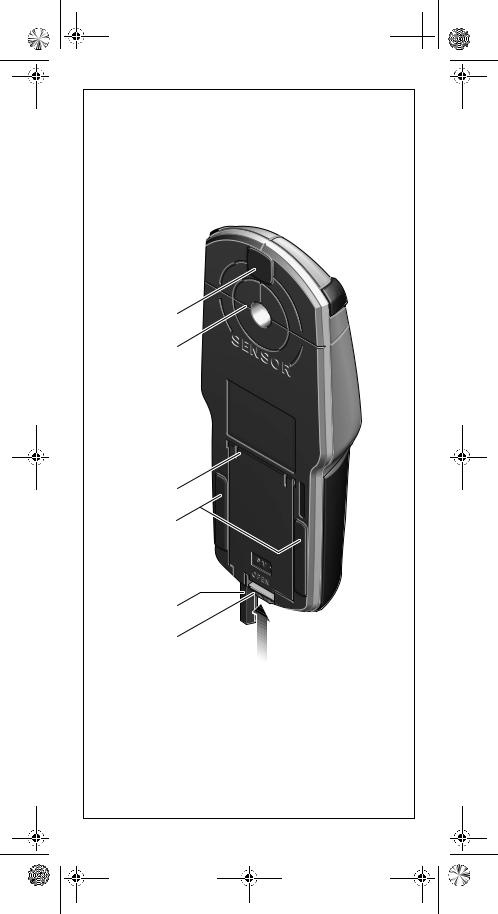
Особенности товара:
Нумерация показанных характеристик продукта относится к изображению измерительного инструмента на графической странице.
- Кольцо с подсветкой
- Отверстие для маркировки
- Монитор
- Кнопка «МАСШТАБ»
- Кнопка обнаружения дерева 6 Кнопка обнаружения металла 7 Кнопка включения/выключения
- Войлочные подушечки
- Площадь сенсора
- Крышка аккумуляторного отсека
- Карандаш для разметки (съемный) 12 Защелка крышки аккумуляторного отсека
Элементы отображения
- Индикатор «живого» провода
- Индикатор обнаружения древесины
- Индикатор обнаружения металла
- Индикатор функции «МАСШТАБ»
- Измерительный индикатор «ZOOM»
- Индикатор измерения
- Индикатор калибровки «AutoCal»
- Индикатор магнитных металлов
- Индикатор немагнитных металлов j Индикатор выключенного звукового сигнала k Индикатор низкого заряда батареи
Изображенные или описанные аксессуары не входят в стандартную поставку.
Технические данные

сборка
Установка / замена батареи
Для работы измерительного инструмента рекомендуется использовать щелочно-марганцевые или аккумуляторные батареи. Чтобы открыть крышку батарейного отсека 10, нажмите на защелку 12 в направлении стрелки и поднимите крышку батарейного отсека. Вставьте прилагаемый аккумулятор. Обратите внимание на правильную полярность в соответствии с изображением на внутренней стороне крышки батарейного отсека. Когда на дисплее загорается индикатор низкого заряда батареи k, измерение еще возможно в течение прибл. 1 час при использовании щелочно-марганцевых батарей (меньший срок службы батарей для перезаряжаемых батарей). Когда индикатор низкого заряда батареи k мигает, измерение возможно в течение прибл. 10 минут. Когда индикатор низкого заряда батареи k и светящееся кольцо 1 (красное) мигают, измерение больше невозможно, и необходимо заменить батарею/аккумулятор.
- Извлекайте батарею/аккумулятор из измерительного инструмента, если он не используется в течение длительного времени. При длительном хранении батареи/аккумуляторы могут подвергнуться коррозии или разрядиться.
Эксплуатация
Начальная операция
Защищайте измерительный инструмент от влаги и прямых солнечных лучей.
Включение и выключение
Перед включением измерительного инструмента убедитесь, что область датчика 9 не влажная. При необходимости протрите измерительный инструмент мягкой тканью.
Не подвергайте измерительный инструмент воздействию экстремальных температур или колебаний температуры. Как бывшийample, не оставляйте его в транспортных средствах на длительное время. В случае больших колебаний температуры дайте измерительному инструменту адаптироваться к температуре окружающей среды, прежде чем включать его в работу.
Избегайте сильных ударов или падения измерительного инструмента.
Для включения включите измерительный инструмент, нажмите любую кнопку. При включении измерительного инструмента кнопкой обнаружения дерева 5 или кнопкой обнаружения металла 6 он автоматически переходит в соответствующую функцию обнаружения. При включении измерительного инструмента кнопкой «вкл./выкл.» 7 или кнопкой «МАСШТАБ» 4 он будет использовать последнюю использовавшуюся функцию обнаружения.
После краткой самопроверки измерительный инструмент готов к работе. Когда измерительный инструмент находится в функции обнаружения металла, готовность к обслуживанию указывается галочкой за индикатором калибровки «AutoCal» g.
Чтобы выключить измерительный инструмент, нажмите кнопку включения/выключения 7. Если ни одна из кнопок измерительного инструмента не будет нажата в течение прибл. Через 5 минут измерительный инструмент автоматически выключается, чтобы продлить срок службы батареи.
Прежде чем сверлить, пилить или фрезеровать стену, защитите себя от опасностей, используя другие источники информации.
. Поскольку на результаты измерения могут влиять условия окружающей среды или материал стены, может существовать опасность, даже если индикатор не указывает на объект в диапазоне действия датчика (нет звукового сигнала или звукового сигнала, а светящееся кольцо 1 горит зеленым) .
Режимы работы
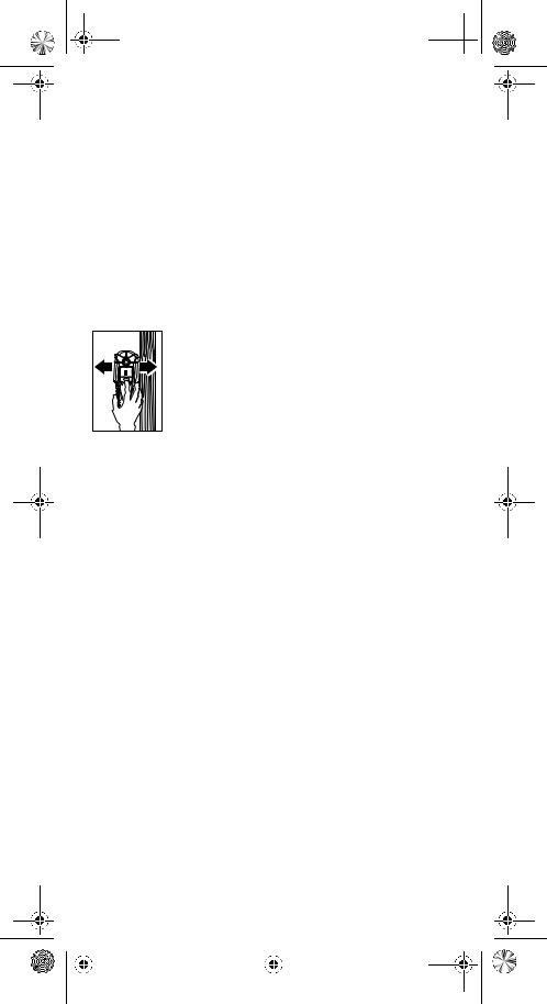
Измерительный инструмент обнаруживает объекты ниже области датчика 9.
Обнаружение металлических предметов
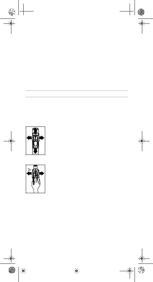
При сканировании металлических объектов нажмите кнопку обнаружения металла 6. На дисплее отображается символ индикатора обнаружения металла c, а светящееся кольцо 1 горит зеленым цветом.
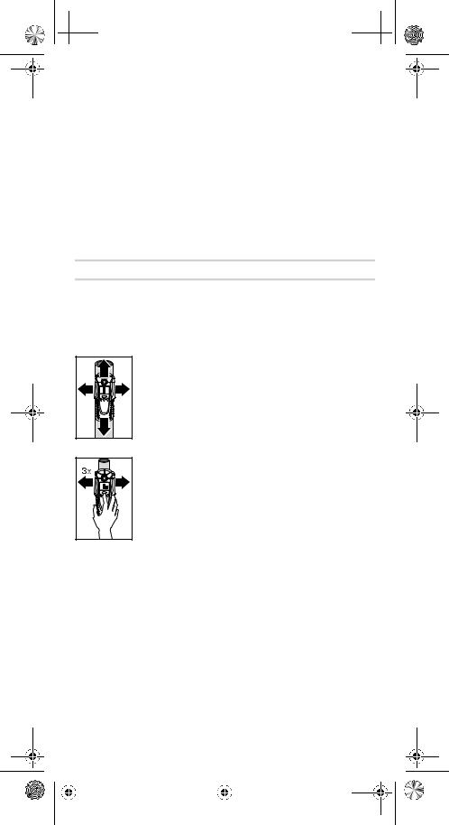
Поместите измерительный инструмент на сканируемую поверхность и переместите его в сторону. Когда измерительный инструмент приближается к металлическому предмету, ampувеличивается высота измерительного индикатора f; когда он удаляется от объекта, ampli-tude уменьшается. В положении максимума ampвысоте, металлический предмет находится ниже центра датчика (ниже маркировочного отверстия

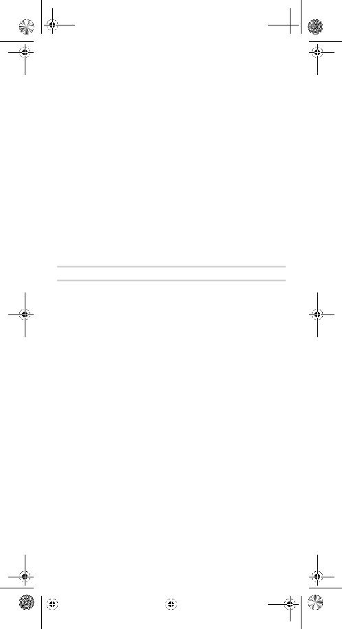
Пока измерительный инструмент находится над металлическим предметом, светящееся кольцо 1 горит красным цветом и звучит ровный звуковой сигнал. Для точной локализации объекта нажмите кнопку «МАСШТАБ» 4 и, удерживая ее, несколько раз (3 раза) перемещайте измерительный инструмент по объекту. На дисплее появится индикатор функции «Масштаб» d. Измерительный показатель «Zoom» e имеет наибольшую ampвысота над центром металлического предмета.
При обнаружении очень мелких или глубоко заглубленных металлических предметов, а измерительный индикатор f не реагирует, нажмите и удерживайте кнопку «МАСШТАБ» 4, продолжая перемещать измерительный инструмент по участку. При сканировании следите только за индикатором измерения увеличения e. Если в сканируемом материале имеются металлические включения, то в измерительном индикаторе f отображается непрерывный сигнал. В этом случае нажмите и удерживайте кнопку «МАСШТАБ» 4, продолжая перемещать измерительный инструмент по участку. При сканировании следите только за измерительным индикатором «Масштаб» e. Если найденный металлический предмет является магнитным (например, железным), то отображается индикатор для магнитных металлов h. Для немагнитных металлов отображается индикатор для немагнитных металлов i. Чтобы измерительный инструмент различал типы металлов, он должен находиться над обнаруженным металлическим предметом (светящееся кольцо 1 горит красным цветом). Для слабых сигналов индикация типа металла невозможна. Для стальной проволочной сетки и арматуры в сканируемом конструкционном материале ampвысота измерительного индикатора f отображается по всей поверхности. В этом случае всегда используйте функцию «Масштаб» для сканирования. Для стальной сетки характерно, что индикатор для магнитных металлов h отображается непосредственно над арматурным стержнем; индикатор для немагнитных металлов i отображается между арматурными стержнями.
Обнаружение деревянных предметов
При сканировании деревянных предметов нажмите кнопку обнаружения дерева 5. На дисплее отображаются символ индикатора обнаружения дерева b и индикатор функции «Масштаб» d, а стрелка под индикатором функции «Масштаб» d мигает. Индикатор калибровки «AutoCal» g и светящееся кольцо 1 гаснут. Поместите измерительный инструмент на сканируемую поверхность. Затем нажмите кнопку «МАСШТАБ» 4 и удерживайте ее нажатой. Теперь светящееся кольцо 1 загорается зеленым цветом, снова отображается индикатор калибровки «AutoCal» g, индикатор функции «Zoom» d и стрелка под ним гаснут.
Удерживая нажатой кнопку «МАСШТАБ» 4, равномерно перемещайте измерительный инструмент над конструкцией, не отрывая его от поверхности и не меняя прикладываемого усилия. Во время сканирования войлочные прокладки 8 должны постоянно соприкасаться с конструкцией.

При обнаружении деревянного предмета ampвысота отображается на индикаторе измерения f. Несколько раз перемещайте измерительный инструмент по поверхности, чтобы точнее определить местоположение деревянного предмета. После нескольких перемещений по одному и тому же участку деревянный предмет можно определить достаточно точно: светящееся кольцо 1 загорается красным, и звучит постоянный звуковой сигнал, пока измерительный инструмент находится над деревянным предметом. Измерительный показатель f имеет наибольшую ampвысота над центром деревянного предмета. Индикатор измерения «Масштаб» e неактивен при сканировании деревянных объектов.
Внимание: При размещении измерительного инструмента на сканируемой поверхности, под которой случайно находится деревянный предмет, и перемещении его по поверхности индикатор измерения f, стрелка под функцией «Масштаб» индикатор d и светящееся кольцо 1 мигают красным цветом. В этом случае снова начните сканирование, переместив измерительный инструмент несколько со смещением относительно конструкции и снова нажав кнопку «МАСШТАБ» 4.
При сканировании деревянных предметов металлические предметы иногда также обозначаются как предметы, найденные на глубине от 20 до 50 мм. Чтобы различать деревянные и металлические предметы, переключитесь на функцию обнаружения металла (см. «Обнаружение металлических предметов»). Когда объект указан в том же месте в этой функции, то это явно металлический, а не деревянный объект. Чтобы продолжить поиск деревянных предметов, вернитесь к функции обнаружения дерева.
Сканирование «живых» проводов
Измерительный инструмент указывает линии, которые несут объемtage от 110 В до 400 В с частотами, соответствующими широко распространенному стандарту (переменный ток с частотой 50 или 60 Гц). Другие линии (постоянный ток, более высокая/низкая частота или громкость)tagд) обозначаются только как металлические предметы. «Живые» провода/проводники обозначаются как при сканировании металла, так и при сканировании дерева. При обнаружении провода/проводника под напряжением на дисплее появляется индикатор a. Несколько раз перемещайте измерительный инструмент по поверхности, чтобы более точно локализовать «находящийся под напряжением» провод/проводник. После нескольких перемещений измерительного инструмента по поверхности можно довольно точно указать «находящийся под напряжением» провод/проводник. Если измерительный инструмент находится очень близко к проводу/проводнику (четыре или пять полосок на индикаторе а), светящееся кольцо 1 мигает красным цветом и звучит сигнал с быстрой последовательностью тонов. «Находящиеся» провода/проводники легче обнаружить, когда потребители энергии (например, лampс, электроприборы) подключаются к искомому проводу/проводнику и включаются. Провода/проводники с напряжением 110 В, 230 В и 400 В (трехфазный ток) обнаруживаются примерно с одинаковой мощностью сканирования.
При определенных условиях (например, за металлическими поверхностями или за поверхностями с высоким содержанием воды) «активные» провода/проводники не могут быть обнаружены с уверенностью. Эти диапазоны могут быть распознаны функцией обнаружения металла. Когда измеряемое значение отображается во всем большем диапазоне измерительного индикатора f, то материал электрически экранируется, и поиск проводов/проводников под напряжением ненадежен.
Провода, которые не находятся под напряжением, могут быть обнаружены как металлические предметы с помощью функции обнаружения металла. Однако многожильные кабели не указаны (в отличие от одножильных медных жил).
Рабочий совет
Измеряемые значения могут ухудшиться из-за определенных условий окружающей среды. К ним относятся, например, близость другого оборудования, создающего сильные магнитные или электромагнитные поля, влага, металлические строительные материалы, ламинированные фольгой изоляционные материалы или проводящие обои или плитка. Поэтому, пожалуйста, ознакомьтесь с другими источниками информации (например, планами строительства) перед тем, как сверлить, пилить или фрезеровать стены, потолки или полы.
Отключение звукового сигнала
Звуковой сигнал можно включать и выключать. Для этого одновременно нажмите кнопку обнаружения металла 6 и кнопку обнаружения дерева 5. Когда звуковой сигнал выключен, на дисплее появляется индикатор выключенного звукового сигнала j. Настройка звукового сигнала сохраняется после выключения и повторного включения измерительного инструмента.
Маркировка объектов
Обнаруженные объекты могут быть помечены по мере необходимости. Для этого снимите карандаш 11 с измерительного инструмента и проведите сканирование как обычно. Как только вы нашли границы или центр объекта, просто отметьте искомое место через маркировочное отверстие 2.
Индикатор калибровки «AutoCal»
Если галочка за индикатором калибровки «AutoCal» g мигает в течение длительного периода времени или если она больше не отображается, надежное сканирование становится невозможным. В этом случае отправьте измерительный инструмент авторизованному агенту Bosch по послепродажному обслуживанию. Исключение: в функции обнаружения деревянных предметов индикатор калибровки «AutoCal» g гаснет, пока не нажата кнопка «ZOOM» 4.
Техобслуживание и сервис
Техническое обслуживание и очистка
Когда измерительный индикатор f постоянно показывает ampli-tude, даже если рядом с измерительным инструментом нет металлических предметов, измерительный инструмент можно откалибровать вручную. Для этого удалите все предметы рядом с измерительным инструментом (включая наручные часы или металлические кольца) и поднимите измерительный инструмент вверх. При выключенном измерительном инструменте нажимайте одновременно кнопку включения/выключения 7 и кнопку обнаружения древесины 5 до тех пор, пока светящееся кольцо 1 не загорится одновременно красным и зеленым цветом. Затем отпустите обе кнопки. Если процесс калибровки прошел успешно, через несколько секунд измерительный инструмент запустится заново и будет готов к работе.
Удалите мусор или загрязнения сухой мягкой тканью. Не используйте чистящие средства или растворители.
Чтобы не влиять на функцию измерения, запрещается прикреплять таблички/наклейки или фирменные таблички, особенно металлические, в зоне датчика 9 на передней или задней стороне измерительного инструмента. Не снимайте войлочные прокладки 8 на задней стороне измерительного инструмента. Замените войлочные прокладки, если они повреждены или используются. Для этого полностью снимите войлочные накладки и на эти же места приклейте новые войлочные накладки. Храните и транспортируйте измерительный инструмент только в прилагаемой защитной сумке. Если измерительный инструмент выйдет из строя, несмотря на тщательные процедуры изготовления и испытания, ремонт должен выполняться в авторизованном центре послепродажного обслуживания электроинструментов Bosch. Не открывайте измерительный инструмент самостоятельно. Во всей корреспонденции и заказах запасных частей всегда указывайте 10-значный артикул, указанный на заводской табличке измерительного инструмента.
Запчасти
Защитный мешочек. . . . . . . . . . . . . . . . . . . . . . . . 1 609 203 Р19
Крышка аккумуляторного отсека 10 . . . . . . . . . . . . . . . . . . . . . . . . . . . 1 609 203 Р32
Войлочные подушечки 8 . . . . . . . . . . . . . . . . . . . . . . . . . . . . . 1 609 203 П21
Послепродажное обслуживание и поддержка клиентов
Наша служба послепродажного обслуживания ответит на ваши вопросы, касающиеся обслуживания и ремонта вашего продукта, а также запасных частей. Взорвался views и информацию о запасных частях также можно найти в разделе:
www.bosch-pt.com Наши представители по обслуживанию клиентов могут ответить на ваши вопросы, касающиеся возможных применений и настройки продуктов и аксессуаров.
Великобритания
Роберт Бош Лтд. (BSC)
Почтовый ящик 98
Бродуотер Парк
Северная Орбитальная дорога
Денхэм
Uxbridge
УБ 9 5HJ
Тел. Сервис: +44 (0844) 736 0109
Факс: + 44 (0844) 736 0146
E-Mail: boschservicecentre@bosch.com
Ирландия
Ориго Лтд.
Блок 23 Magna Drive
Бизнес-парк Magna
Город Запад
Дублин 24
Тел. Сервис: +353 (01) 4 66 67 00
Факс: + 353 (01) 4 66 68 88
Австралия, Новая Зеландия и острова Тихого океана
Роберт Бош Австралия Pty. Ltd.
Электроинструмент
Запертая сумка 66
Клейтон Саут Виктория 3169
Центр обслуживания клиентов
Внутри Австралии:
Телефон: + 61 (01300) 307 044
Факс: + 61 (01300) 307 045
Внутри Новой Зеландии:
Телефон: + 64 (0800) 543 353
Факс: + 64 (0800) 428 570
За пределами Австралии и Новой Зеландии:
Телефон: + 61 (03) 9541 5555
www.bosch.com.ua
ЮАР Служба поддержки клиентов
Горячая линия: +27 (011) 6 51 96 00
Гаутенг — Сервисный центр BSC
35 Roper Street, New Center Йоханнесбург
Телефон: + 27 (011) 4 93 93 75
Факс: + 27 (011) 4 93 01 26
E-Mail: bsctools@icon.co.za
KZN — Сервисный центр BSC
Блок E, Центр Алмара
143 Кромптон-стрит
Pinetown
Телефон: + 27 (031) 7 01 21 20
Факс: + 27 (031) 7 01 24 46
E-Mail: bsc.dur@za.bosch.com
Западный Кейп — Сервисный центр BSC
Демократия Путь, Парк процветания Милнертон
Телефон: + 27 (021) 5 51 25 77
Факс: + 27 (021) 5 51 32 23
E-Mail: bsc@zsd.co.za
Главный офис Bosch
Мидранд, Гаутенг
Телефон: + 27 (011) 6 51 96 00
Факс: + 27 (011) 6 51 98 80
E-Mail: rbsa-hq.pts@za.bosch.com
Китайская Народная Республика Материковый Китай
Bosch Power Tools (Китай) Co., Ltd.
567, Бин Кан Роуд
Район Бин Цзян 310052
Ханчжоу, Китай
Горячая линия обслуживания: 400 826 8484
TG: @t_kofip
E-Mail: kcontact.ptcn@cn.bosch.com
www.bosch-pt.com.cn
Специальные административные районы Гонконг и Макао Robert Bosch Hong Kong Co. Ltd.
21-й этаж, 625 King’s Road
Норт Пойнт, Гонконг
Горячая линия обслуживания клиентов: +852 (21) 02 02 35 Факс: +852 (25) 90 97 62
E-Mail: info@hk.bosch.com
www.bosch-pt.com.hk
Индонезия
PT. Мульти Техака
Kawasan Industri Пулогадунг
Джалан Рава Гелам III № 2
Jakarta 13930
Индонезия
Телефон: + 62 (21) 46 83 25 22
Факс: +62 (21) 46 82 86 45/68 23
E-Mail: ksales@multitehaka.co.id
www.multitehaka.co.id
Филиппины
Роберт Бош, Inc.
28-й этаж Fort Legend Towers,
3-я авеню, угол 31-я улица,
Форт Бонифачо Глобал Сити,
1634 Taguig City, Филиппины
Тел.: + 63 (2) 870 3871
Факс: + 63 (2) 870 3870
matheus.contiero@ph.bosch.com
www.bosch-pt.com.ph
Сервисный центр Bosch:
9725-27 улица Камагонг
Сан — Антонио деревня
Макати, Филиппины
Тел.: + 63 (2) 899 9091
Факс: + 63 (2) 897 6432
rosalie.dagdagan@ph.bosch.com
Малайзия
Роберт Бош (SEA) Pte. ООО
№ 8А, Джалан 13/6
GPO Box 10818
46200 Петалинг Джая
Селангор, Малайзия
Тел.: + 60 (3) 7966 3194
Факс: + 60 (3) 7958 3838
cheehoe.on@my.bosch.com
Бесплатный номер: 1800 880 188
www.bosch-pt.com.my
Таиланд
Роберт Бош Лтд.
Здание на площади Свободы
№ 287, 11 этаж
Силом Роуд, Банграк
Бангкок 10500
Тел.: +66 (2) 6 31 18 79 – 18 88 (10 линий) Факс: +66 (2) 2 38 47 83
Robert Bosch Ltd., PO Box 2054 Бангкок 10501, Таиланд
Bosch Service — Учебный центр
2869-2869 / 1 Soi Ban Kluay
Рама IV Роуд (возле старой железной дороги Пакнам) Район Праканонг
10110 Бангкок
Таиланд
Тел .: +66 (2) 6 71 78 00 — 4
Факс: + 66 (2) 2 49 42 96
Факс: + 66 (2) 2 49 52 99
Сингапур
Роберт Бош (SEA) Pte. ООО
11 улица Бишан, 21
Сингапур 573943
Тел .: + 65 6571 2772
Факс: + 65 6350 5315
leongheng.leow@sg.bosch.com
Бесплатный номер: 1800 333 8333
www.bosch-pt.com.sg
Вьетнам
Роберт Бош Вьетнам Ко. Лтд.
10 / F, 194 Golden Building
улица Дьенбьенфу, 473
Район 25, район Бинь Тхань
84 Хошимин
Вьетнам
Тел .: +84 (8) 6258 3690 доб. 413
Факс: + 84 (8) 6258 3692
khieu.lagia@vn.bosch.com
www.bosch-pt.com
Распоряжение
Измерительные инструменты, аксессуары и упаковка должны быть отправлены на экологически безопасную переработку. Не выбрасывайте измерительные инструменты и батарейки / аккумуляторы вместе с бытовым мусором!
Только для стран ЕС:
В соответствии с Европейской директивой 2002/96/ЕС измерительные инструменты, которые более не пригодны для использования, и согласно Европейской директиве 2006/66/ЕС, дефектные или использованные аккумуляторные блоки/батарейки должны собираться отдельно и утилизироваться в экологически правильным образом.
Батареи, больше не пригодные для использования, можно вернуть по адресу:
Великобритания
Роберт Бош Лтд. (BSC)
Почтовый ящик 98
Бродуотер Парк
Северная Орбитальная дорога
Денхэм
Uxbridge
УБ 9 5HJ
Тел. Сервис: +44 (0844) 736 0109
Факс: + 44 (0844) 736 0146
E-Mail: boschservicecentre@bosch.co
Документы / Ресурсы
-
Contents
-
Table of Contents
-
Bookmarks
-
ENGLISH, page 11
-
FRANÇAIS, page 18
-
ESPAÑOL, página 25
-
DEUTSCH, seite 4
-
ITALIANO, pagina 40
-
DUTCH, pagina 47
-
PORTUGUÊS, página 33
-
SVENSKA, sida 60
-
DANSK, side 54
-
SUOMI, sivu 72
-
NORSK, side 66
-
ΕΛΛΗΝΙΚΆ, σελίδα 78
-
TÜRKÇE, sayfa 86
-
日本語, 92ページ
Quick Links
Bedienungsanleitung
Operating instructions
Instructions d’emploi
Instrucciones de
servicio
PDO Multi
Manual de instruções
Istruzioni d’uso
Gebruiksaanwijzing
Betjeningsvejledning
Bruksanvisning
Brukerveiledningen
Käyttöohje
Οδηγία χειρισµού
Kullanım kılavuzu
取扱説明書
Deutsch
English
P D
Français
O
M u
l t i
Español
Português
Italiano
Nederlands
Dansk
Svenska
Norsk
Suomi
Ελληνικά
Türkçe
日本語
Summary of Contents for Bosch PDO Multi
![]()
OBJ_BUCH-1 609 929 J68-001.book Page 1 Monday, January 30, 2006 11:20 AM 
Bedienungsanleitung Operating instructions Instructions d’emploi Instrucciones de servicio
Manual de instruções Istruzioni d’uso Gebruiksaanwijzing Betjeningsvejledning Bruksanvisning Brukerveiledningen Käyttöohje
δηγία ειρισµ ύ
Kullanım kılavuzu
PDO Multi
|
Deutsch |
||||
|
English |
P |
|||
|
Français |
DO |
Multi |
||
|
Español |
||||
|
Português |
||||
|
Italiano |
||||
|
Nederlands |
||||
|
Dansk |
||||
|
Svenska |
||||
|
Norsk |
||||
|
Suomi |
||||
|
Ελληνικά |
||||
|
Türkçe |
OBJ_BUCH-1 609 929 J68-001.book Page 2 Monday, January 30, 2006 11:20 AM 
SENSOR
9V OPEN
1 609 929 J68 • 30.1.06

OBJ_BUCH-1 609 929 J68-001.book Page 3 Monday, January 30, 2006 11:20 AM 
1 609 929 J68 • 30.1.06

OBJ_BUCH-1 609 929 J68-001.book Page 1 Monday, January 30, 2006 11:20 AM 
Funktionsbeschreibung
Optimales Arbeiten mit dem Messwerkzeug ist nur möglich, wenn Sie die Bedienungsanleitung und die Arbeitshinweise vollständig lesen und die darin enthaltenen Anweisungen strikt befolgen. BEWAHREN SIE DIESE ANWEISUNGEN GUT AUF.
Bitte klappen Sie die Ausklappseite mit der Darstellung des Messwerkzeugs auf, und lassen Sie diese Seite aufgeklappt, während Sie die Bedienungsanleitung lesen.
Bestimmungsgemäßer Gebrauch
Das Messwerkzeug ist bestimmt zur Suche nach Metallen (Eisenund Nichteisenmetalle, z.B. Armierungseisen), Holzbalken sowie spannungsführenden Leitungen in Wänden, Decken und Fußböden.
Abgebildete Komponenten
Die Nummerierung der abgebildeten Komponenten bezieht sich auf die Darstellung des Messwerkzeugs auf der Grafikseite.
1 Leuchtring
2 Markierungsöffnung
3 Display
4 Taste „ZOOM“
5 Taste für Holzsuche
6 Taste für Metallsuche
7 Ein-Aus-Taste „on/off“
8 Filzgleiter
9 Sensorbereich
10Batteriefachdeckel
11Bleistift zum Markieren (herausnehmbar)
12Arretierung des Batteriefachdeckels
Anzeigenelemente
a Anzeige von spannungsführenden Leitungen b Anzeige der Funktion Holzsuche
c Anzeige der Funktion Metallsuche d Anzeige der Funktion „ZOOM“
e Messanzeige „ZOOM“ f Messanzeige
g Kalibrierungsanzeige „AutoCal“ h Anzeige magnetischer Metalle
i Anzeige nichtmagnetischer Metalle
j Anzeige für abgeschalteten Signalton k Batterie-Anzeige
|
1 609 929 J68 • 30.1.06 |
Deutsch–1 |
|||||
OBJ_BUCH-1 609 929 J68-001.book Page 2 Monday, January 30, 2006 11:20 AM 
Technische Daten
|
Digitales Ortungsgerät |
PDO Multi |
|
Sachnummer |
3 603 K10 000 |
|
max. Erfassungstiefe*: |
|
|
Eisenmetalle |
80 mm |
|
Nichteisenmetalle (Kupfer) |
60 mm |
|
Kupferleitungen (spannungsführend)** |
40 mm |
|
Holz |
20 mm |
|
Abschaltautomatik nach ca. |
5 min |
|
Betriebstemperatur |
–10 °C … +50 °C |
|
Lagertemperatur |
–20 °C … +70 °C |
|
Batterie |
1 x 9 V 6LR61 |
|
Akku |
1 x 9 V 6F22 |
|
Betriebsdauer (Alkali-Mangan-Batterie) ca. |
6 h |
|
Gewicht entsprechend EPTA-Procedure 01/2003 |
0,25 kg |
* abhängig von Material und Größe der Objekte sowie Material und Zustand des Untergrundes
** geringere Erfassungstiefe bei nicht spannungsführenden Leitungen
Bitte beachten Sie die Sachnummer auf dem Typenschild Ihres Messwerkzeugs, die Handelsbezeichnungen einzelner Messwerkzeuge können variieren.
Betrieb
Batterien einsetzen/wechseln
Verwenden Sie ausschließlich Alkali-Mangan-Batterien oder Akkus.
Zum Öffnen des Batteriefachdeckels 10 drücken Sie die Arretierung 12 in Pfeilrichtung und klappen den Batteriefachdeckel hoch. Setzen Sie die mitgelieferte Batterie ein. Achten Sie dabei auf die richtige Polung entsprechend der Darstellung auf der Innenseite des Batteriefachs.
Leuchtet die Batterie-Anzeige k im Display auf, dann können Sie bei Verwendung von Alkali-Mangan-Batterien noch ca. 1 Stunde messen (bei Akkus kürzere Standzeit). Blinkt die Anzeige k, dann sind noch ca. 10 min Messung möglich. Blinken die Batterie-Anzeige k und der Leuchtring 1 (rot), dann ist keine Messung mehr möglich und Sie müssen die Batterie bzw. den Akku wechseln.
BNehmen Sie die Batterie aus dem Messwerkzeug, wenn Sie es längere Zeit nicht benutzen. Die Batterie kann bei längerer Lagerung korrodieren oder sich selbst entladen.
Inbetriebnahme
Schützen Sie das Messwerkzeug vor Nässe und direkter Sonneneinstrahlung.
Ein-/Ausschalten
BStellen Sie vor dem Einschalten des Messwerkzeugs sicher, dass der Sensorbereich 9 nicht feucht ist. Reiben Sie das Messwerkzeug gegebenenfalls mit einem Tuch trocken.
BWar das Messwerkzeug einem starken Temperaturwechsel ausgesetzt, dann lassen Sie es vor dem Einschalten austemperieren.
|
1 609 929 J68 • 30.1.06 |
Deutsch–2 |
|||||

 OBJ_BUCH-1 609 929 J68-001.book Page 3 Monday, January 30, 2006 11:20 AM
Zum Einschalten des Messwerkzeugs drücken Sie eine beliebige Taste.
Wenn Sie das Messwerkzeug mit der Taste für Holzsuche 5 oder mit der Taste für Metallsuche 6 einschalten, dann befindet es sich sofort in der entsprechenden Suchfunktion.
Wenn Sie das Messwerkzeug mit der Ein-Aus-Taste 7 oder der Taste „ZOOM“ 4 einschalten, dann befindet es sich in der Suchfunktion, in der es zuletzt verwendet wurde.
Nach einem kurzen Selbsttest ist das Messwerkzeug betriebsbereit. Befindet sich das Messwerkzeug in der Funktion Metallsuche, dann wird die Betriebsbereitschaft durch einen Haken hinter der Kalibrierungsanzeige
„AutoCal“ g angezeigt.
Zum Ausschalten des Messwerkzeugs drücken Sie die Ein-Aus-Taste 7.
Wird ca. 5 min lang keine Taste am Messwerkzeug gedrückt, dann schaltet sich das Messwerkzeug zur Schonung der Batterie automatisch ab.
Betriebsarten
Das Messwerkzeug detektiert Objekte unterhalb des Sensorbereiches 9.
Metallobjekte suchen
Drücken Sie für die Suche nach Metallobjekten die Taste für Metallsuche 6. Im Display wird das Symbol c für Metallsuche angezeigt, der Ring 1 leuchtet grün.
Setzen Sie das Messwerkzeug auf die zu untersuchende Oberfläche und bewegen Sie es seitlich. Nähert sich das Messwerkzeug einem Metallobjekt, dann nimmt der Ausschlag in der Messanzeige f zu, entfernt es sich von dem Objekt, dann nimmt der Ausschlag ab. An der Position des maximalen Ausschlages befindet sich das Metallobjekt unterhalb der Sensormitte (unterhalb der Markierungsöffnung 2). Solange sich das Messwerkzeug über dem Metallobjekt befindet, leuchtet der Ring 1 rot und es ertönt ein Dauerton.
Drücken Sie für eine genaue Lokalisierung des Objektes die Taste „ZOOM“ 4 und halten Sie sie gedrückt, während Sie das Messwerkzeug wiederholt (3x) über das Objekt bewegen. Im Display erscheint die Anzeige der Zoom-Funktion d. Über der Mitte des Metallobjektes hat die Zoom-Messanzeige e den größten Ausschlag.
Werden sehr kleine oder tief liegende Metallobjekte gesucht und die Messanzeige f schlägt nicht aus, dann drücken Sie die Taste „ZOOM“ 4 und halten Sie sie gedrückt, während
Sie den Bereich weiter überfahren. Beachten Sie für die Suche nur die Zoom-Messanzeige e.
Befinden sich im zu untersuchenden Material metallische Einschlüsse, dann wird in der Messanzeige f ein Dauersignal angezeigt. Drücken Sie dann die Taste „ZOOM“ 4 und halten Sie sie gedrückt, während Sie den Bereich weiter überfahren. Beachten Sie für die Suche nur die ZoomMessanzeige e.
Handelt es sich bei dem gefundenen metallischen Objekt um ein magnetisches Metall (z.B. Eisen), so wird im Display das Symbol h angezeigt. Bei nichtmagnetischen Metallen wird das Symbol i angezeigt. Für die Unterscheidung zwischen den Metallarten muss sich das Messwerkzeug über dem gefundenen Metallobjekt befinden (Ring 1 leuchtet rot). Bei schwachen Signalen ist die Anzeige der Metallart nicht möglich.
|
1 609 929 J68 • 30.1.06 |
Deutsch–3 |
|||||
OBJ_BUCH-1 609 929 J68-001.book Page 4 Monday, January 30, 2006 11:20 AM 
Bei Baustahlmatten und Armierungen im untersuchten Untergrund wird über der gesamten Fläche ein Ausschlag in der Messanzeige f angezeigt. Verwenden Sie in diesem Fall immer die Zoom-Funktion für die Suche. Typischerweise wird bei Baustahlmatten direkt über den Eisenstäben im Display das Symbol h für magnetische Metalle angezeigt, zwischen den Eisenstäben erscheint das Symbol i für nichtmagnetische Metalle.
Holzobjekte suchen
Drücken Sie für die Suche nach Holzobjekten die Taste für Holzsuche 5. Im Display werden das Symbol b für Holzsuche und die Anzeige der ZoomFunktion d angezeigt, der Pfeil unterhalb der Zoom-Anzeige d blinkt. Die Kalibrierungsanzeige „AutoCal“ g und der Ring 1 erlöschen.
Setzen Sie das Messwerkzeug auf die zu untersuchende Fläche auf. Drücken Sie erst dann die Taste „ZOOM“ 4 und halten Sie sie gedrückt. Der Leuchtring 1 leuchtet nun grün, die Kalibrierungsanzeige „AutoCal“ g wird wieder angezeigt, die Anzeige der Zoom-Funktion d sowie der Pfeil darunter erlöschen.
Bewegen Sie das Messwerkzeug mit gedrückter Taste „ZOOM“ 4 gleichmäßig über den Untergrund, ohne es abzuheben oder den Anpressdruck zu verändern. Während der Messung müssen die Filzgleiter 8 immer Kontakt zum Untergrund haben.
Wird ein Holzobjekt gefunden, schlägt die Messanzeige f aus. Bewegen Sie das Messwerkzeug wiederholt über die Fläche, um das Holzobjekt genauer zu lokalisieren. Nach
mehrmaligem Überfahren des gleichen Bereiches kann das Holzobjekt sehr genau angezeigt werden: Solange sich das Messwerkzeug über dem Holzobjekt befindet, leuchtet der Ring 1 rot und es ertönt ein Dauerton. Über der Mitte des Holzobjektes hat die Messanzeige f den größten Ausschlag. Die Zoom-Messanzeige e ist bei der Suche nach Holzobjekten nicht aktiv.
Achtung: Wenn Sie das Messwerkzeug zufällig über einem Holzobjekt auf die zu untersuchende Fläche aufgesetzt und über die Fläche bewegt haben, dann blinken die Messanzeige f sowie der Pfeil unter der ZoomAnzeige d, und der Leuchtring 1 blinkt rot. Beginnen Sie in diesem Fall die Messung neu, indem Sie das Messwerkzeug etwas versetzt wieder auf den Untergrund setzen und die Taste „ZOOM“ 4 erneut drücken.
Bei der Suche nach Holzobjekten werden teilweise auch Metallobjekte in einer Tiefe von 20–50 mm als gefundene Objekte angezeigt. Zur Unterscheidung zwischen Holzund Metallobjekten wechseln Sie in die Funktion Metallsuche (siehe „Metallobjekte suchen“). Wird in dieser Funktion an der gleichen Stelle ein Objekt angezeigt, dann ist es eindeutig ein Metall-, kein Holzobjekt. Wechseln Sie zur weiteren Suche nach Holzobjekten zurück in die Funktion Holzsuche.
Spannungsführende Leitungen suchen
Das Messwerkzeug zeigt Leitungen an, die Spannung zwischen 110 V und 400 V führen und deren Frequenz dem weit verbreiteten Standard (Wechselstrom mit 50 bzw. 60 Hz) entspricht. Andere Leitungen (Gleichstrom, höhere/niedrigere Frequenz oder Spannung) werden nur als Metallobjekte angezeigt.
Spannungsführende Leitungen werden sowohl während einer Metallsuche als auch während einer Holzsuche angezeigt. Wird eine spannungsführende Leitung gefunden, dann erscheint im Display die Anzeige a. Bewegen Sie das Messwerkzeug wiederholt über die Fläche, um die spannungsführende Leitung genauer zu lokalisieren. Nach mehrmaligem Überfahren kann die spannungsführende Leitung sehr genau angezeigt werden. Ist das Messwerkzeug sehr nahe an der Leitung (vier bzw. fünf Balken in der Anzeige a), dann blinkt der Leuchtring 1 rot und der Signalton ertönt mit schneller Tonfolge.
|
1 609 929 J68 • 30.1.06 |
Deutsch–4 |
|||||

OBJ_BUCH-1 609 929 J68-001.book Page 5 Monday, January 30, 2006 11:20 AM 
Spannungsführende Leitungen können leichter gefunden werden, wenn Stromverbraucher (z.B. Leuchten, Geräte) an der gesuchten Leitung angeschlossen und eingeschaltet werden. Leitungen mit 110 V, 230 V und 400 V (Drehstrom) werden mit ungefähr derselben Suchleistung gefunden.
Unter bestimmten Bedingungen (wie z.B. hinter Metalloberflächen oder hinter Oberflächen mit hohem Wassergehalt) können spannungsführende Leitungen nicht sicher gefunden werden. Sie erkennen diese Bereiche in der Funktion Metallsuche. Wird über einem größeren Bereich überall ein Messwert f angezeigt, dann schirmt das Material elektrisch ab und die Suche nach spannungsführenden Leitungen ist nicht zuverlässig.
Nicht spannungsführende Leitungen können Sie als Metallobjekte mit der Funktion Metallsuche finden. Litzenkabel werden dabei nicht angezeigt (im Gegensatz zu Vollmaterialkabeln).
Arbeitshinweise
BDie Messergebnisse können prinzipbedingt durch bestimmte Umgebungsbedingungen beeinträchtigt werden. Dazu gehören z.B. die Nähe von Geräten, die starke magnetische oder elektromagnetische Felder erzeugen, Nässe, metallhaltige Baumaterialien, alukaschierte Dämmstoffe oder leitfähige Tapeten. Beachten Sie deshalb vor dem Bohren, Sägen oder Fräsen in Wände, Decken oder Böden auch andere Informationsquellen (z.B. Baupläne).
Signalton abschalten
Sie können den Signalton abund anschalten. Drücken Sie dazu die Tasten für Metallsuche 6 und für Holzsuche 5 gleichzeitig. Bei abgeschaltetem Signalton erscheint im Display die Anzeige j.
Die Einstellung des Signaltons bleibt beim Ausund Einschalten des Messwerkzeugs erhalten.
Objekte markieren
Sie können gefundene Objekte bei Bedarf markieren. Nehmen Sie dazu den Bleistift 11 aus dem Messwerkzeug und messen Sie wie gewohnt. Haben Sie die Grenzen oder die Mitte eines Objektes gefunden, dann markieren Sie die gesuchte Stelle durch die Markierungsöffnung 2.
Anzeige „AutoCal“
Blinkt der Haken hinter der Kalibrierungsanzeige „AutoCal“ g über längere Zeit oder wird er nicht mehr angezeigt, kann nicht mehr zuverlässig gemessen werden. Senden Sie das Messwerkzeug in diesem Fall an eine autorisierte Bosch-Kundendienststelle. Ausnahme: In der Funktion Holzsuche erlischt die Kalibrierungsanzeige „AutoCal“ g, solange die Taste „ZOOM“ 4 nicht gedrückt wird.
|
1 609 929 J68 • 30.1.06 |
Deutsch–5 |
|||||

OBJ_BUCH-1 609 929 J68-001.book Page 6 Monday, January 30, 2006 11:20 AM 
Wartung und Service
Wartung und Reinigung
Schlägt die Messanzeige f dauerhaft aus, obwohl sich kein Objekt aus Metall in der Nähe des Messwerkzeugs befindet, kann das Messwerkzeug manuell kalibriert werden. Entfernen Sie dazu alle Objekte aus der Nähe des Messwerkzeugs (auch Armbanduhr oder Ring aus Metall) und halten Sie das Messwerkzeug in die Luft. Drücken Sie bei ausgeschaltetem Messwerkzeug die Ein-Aus-Taste 7 und die Taste für Holzsuche 5 so lange gleichzeitig, bis der Leuchtring 1 gleichzeitig rot und grün leuchtet. Lassen Sie dann beide Tasten los. Verlief die Kalibrierung erfolgreich, dann startet das Messwerkzeug nach einigen Sekunden neu und ist wieder betriebsbereit.
Wischen Sie Verschmutzungen mit einem trockenen, weichen Tuch ab. Verwenden Sie keine Reinigungsoder Lösemittel.
Um die Messfunktion nicht zu beeinflussen, dürfen im Sensorbereich 9 auf der Vorderund Rückseite des Messwerkzeugs keine Aufkleber oder Schilder, insbesondere keine Schilder aus Metall, angebracht werden.
Entfernen Sie die Filzgleiter 8 auf der Rückseite des Messwerkzeugs nicht. Ersetzen Sie die Filzgleiter, wenn sie beschädigt oder abgenutzt sind. Entfernen Sie dazu die beschädigten Filzgleiter vollständig und kleben Sie die neuen Filzgleiter auf der gleichen Stelle auf.
Lagern und transportieren Sie das Messwerkzeug nur in der mitgelieferten Schutztasche.
Sollte das Messwerkzeug trotz sorgfältiger Herstellungsund Prüfverfahren einmal ausfallen, ist die Reparatur von einer autorisierten Kundendienststelle für Bosch-Elektrowerkzeuge ausführen zu lassen.
Geben Sie bei allen Rückfragen und Ersatzteilbestellungen bitte unbedingt die 10-stellige Sachnummer laut Typenschild des Messwerkzeugs an.
Ersatzteile
Schutztasche . . . . . . . . . . . . . . . . . . . . . . . . . . . . . . . . . . . . . 1 609 203 P19
Batteriefachdeckel 10. . . . . . . . . . . . . . . . . . . . . . . . . . . . . . 1 609 203 R32
Filzgleiter 8. . . . . . . . . . . . . . . . . . . . . . . . . . . . . . . . . . . . . . . 1 609 203 P21
Service und Kundenberater
Explosionszeichnungen und Informationen zu Ersatzteilen finden Sie unter: www.bosch-pt.com
www.powertool-portal.de, das Internetportal für Heimwerker und Gartenfreunde.
www.dha.de, das komplette Service-Angebot der Deutschen Heimwerker Akademie.
Deutschland
Robert Bosch GmbH Servicezentrum Elektrowerkzeuge Zur Luhne 2
37589 Kalefeld
. . . . . . . . . . . . . . . . . . . . . . . . . . . . . . . . . . . . . . . . . . . . 0 18 05/70 74 10 Fax . . . . . . . . . . . . . . . . . . . . . . . . . . . . . . . . . . . . . . . . . . . 0 18 05/70 74 11
|
1 609 929 J68 • 30.1.06 |
Deutsch–6 |
|||||
OBJ_BUCH-1 609 929 J68-001.book Page 7 Monday, January 30, 2006 11:20 AM 
Österreich
ABE Service GmbH Jochen-Rindt-Straße 1 1232 Wien
Service . . . . . . . . . . . . . . . . . . . . . . . . . . . . . . . . . . . . . +43 (0)1/61 03 80 Fax . . . . . . . . . . . . . . . . . . . . . . . . . . . . . . . . . . . . . . . +43 (0)1/61 03 84 91Kundenberater . . . . . . . . . . . . . . . . . . . . . . . . . +43 (0)1/7 97 22 30 66 E-Mail: abe@abe-service.co.at
Schweiz
. . . . . . . . . . . . . . . . . . . . . . . . . . . . . . . . . . . . . . . . . . . . . 0 44/8 47 15 11 Fax . . . . . . . . . . . . . . . . . . . . . . . . . . . . . . . . . . . . . . . . . . . . 0 44/8 47 15 51
Luxemburg
. . . . . . . . . . . . . . . . . . . . . . . . . . . . . . . . . . . . . . . . . .+32 (0)70/22 55 65 Fax . . . . . . . . . . . . . . . . . . . . . . . . . . . . . . . . . . . . . . . . .+32 (0)70/22 55 75 E-Mail: outillage.gereedschap@be.bosch.com
Entsorgung
Messwerkzeuge, Zubehör und Verpackungen sollen einer umweltgerechten Wiederverwertung zugeführt werden.
Nur für EU-Länder:
Werfen Sie Messwerkzeuge nicht in den Hausmüll! Gemäß der Europäischen Richtlinie 2002/96/EG über Elektround Elektronik-Altgeräte und ihrer Umsetzung in nationales Recht müssen nicht mehr gebrauchsfähige Messwerkzeuge getrennt gesammelt und einer umweltgerechten Wiederverwertung zugeführt werden.
Akkus/Batterien:
Werfen Sie Akkus/Batterien nicht in den Hausmüll, ins Feuer oder ins Wasser. Akkus/Batterien sollen gesammelt, recycelt oder auf umweltfreundliche Weise entsorgt werden.
Nur für EU-Länder:
Gemäß der Richtlinie 91/157/EWG müssen defekte oder verbrauchte Akkus/Batterien recycelt werden.
Nicht mehr gebrauchsfähige Akkus/Batterien können direkt abgegeben werden bei:
Deutschland
Recyclingzentrum Elektrowerkzeuge Osteroder Landstraße 3
37589 Kalefeld
Schweiz
Batrec AG
3752 Wimmis BE
Änderungen vorbehalten.
|
1 609 929 J68 • 30.1.06 |
Deutsch–7 |
|||||
![]()
OBJ_BUCH-1 609 929 J68-001.book Page 1 Monday, January 30, 2006 11:20 AM 
Functional Description
Optimal working with the measuring tool is possible only when the operating instructions and information are read completely, and the instructions contained therein are strictly followed. SAVE THESE INSTRUCTIONS.
Please unfold the fold-out page with the representation of the measuring tool and leave it unfolded while reading the operating instructions.
Intended Use
The measuring tool is intended for the detection of metals (ferrous and nonferrous metals, e.g., rebar), joists and “live” wires/conductors in walls, ceilings and floors.
Product Features
The numbering of the product features shown refers to the illustration of the measuring tool on the graphic page.
1 Illuminated ring
2 Marking hole
3 Display
4 “ZOOM” button
5 Wood-detection button
6 Metal-detection button
7 “on/off” button
8 Felt pads
9 Sensor area
10Battery lid
11Pencil for marking (removable)
12Latch of battery lid
Display Elements
a “Live” wire indicator
b Wood detection indicator c Metal detection indicator
d “ZOOM” function indicator
e “ZOOM” measuring indicator f Measuring indicator
g “AutoCal” calibration indicator h Indicator for magnetic metals
i Indicator for non-magnetic metals j Switched-off audio signal indicator k Battery indication
|
1 609 929 J68 • 30.1.06 |
English–1 |
|||||
OBJ_BUCH-1 609 929 J68-001.book Page 2 Monday, January 30, 2006 11:20 AM 
Technical Data
|
Digital Detector |
PDO Multi |
|
Article number |
3 603 K10 000 |
|
Maximum scanning depth*: |
|
|
Ferrous metals |
80 mm |
|
Non-ferrous metals (copper) |
60 mm |
|
Copper conductors (live)** |
40 mm |
|
Wood |
20 mm |
|
Automatic switch-off after approx. |
5 min |
|
Operating temperature |
–10 °C … +50 °C |
|
Storage temperature |
–20 °C … +70 °C |
|
Battery |
1 x 9 V 6LR61 |
|
Rechargeable battery |
1 x 9 V 6F22 |
|
Operating lifetime |
|
|
(alkali-manganese batteries) approx. |
6 h |
|
Weight according to EPTA-Procedure 01/2003 |
0.25 kg |
* depends on material and size of objects as well as material and condition of structure
** less scanning depth for wires/conductors that are not “live”
Please observe the article number on the type plate of your measuring tool. The trade names of the individual measuring tools may vary.
Operation
Inserting/Replacing the Battery
Use only alkali-manganese or rechargeable batteries.
To open the battery lid 10, press the latch 12 in the direction of the arrow and fold up the battery lid. Insert the supplied battery. Pay attention that the polarity is correct, according to the representation on the inside of the battery lid.
When the battery indication k in the display lights up, measuring is possible for approx. 1 h when using alkali-manganese batteries (service life is shorter with rechargeable batteries). When the battery indication k flashes, measuring is still possible for approx. 10 minutes. When the battery indication k and the illuminated ring 1 (red) are flashing, measuring is no longer possible and the battery or the rechargeable battery respectively, must be replaced.
BIf the measuring tool is not used for a long period of time, the battery must be removed. The battery can corrode or discharge itself over long periods.
Initial Operation
Protect the measuring tool against moisture and direct sun irradiation.
Switching On and Off
BBefore switching the measuring tool on, make sure that the sensor area 9 is not moist. If required, wipe the measuring tool dry using a cloth.
BIf the measuring tool was subject to an extreme temperature change, allow it to adjust to the ambient temperature before switching on.
|
1 609 929 J68 • 30.1.06 |
English–2 |
|||||
 OBJ_BUCH-1 609 929 J68-001.book Page 3 Monday, January 30, 2006 11:20 AM
To switch on switch on the measuring tool on, press any button.
When switching the measuring tool on with the wood-detection button 5 or with the metal-detection button 6, it will automatically be in the respective detection function.
When switching the measuring tool on with the “on/off” button 7 or with the “ZOOM” button 4, it will be in the detection function last used.
After a brief self-check, the measuring tool is ready for operation. When the measuring tool is in the metal-detection function, the service readiness is indicated through a check mark behind the “AutoCal” calibration indicator g.
To switch the measuring tool off, press the “on/off” button 7.
If none of the measuring tool buttons are pressed for approx. 5 minutes, the measuring tool switches off automatically in order to extend the service life of the battery.
Operating Modes
The measuring tool detects objects below the sensor area 9.
Detecting Metal Objects
When scanning for metal objects, press the metal-detection button 6. The metal detection indicator symbol c is indicated in the display and the illuminated ring 1 lights up green.
Place the measuring tool on the surface to be scanned and move it sidewards. When the measuring tool comes close to a metal object, the amplitude in the measuring indicator f increases and when it is moved away, the measuring indicator decreases. At the position of the maximum amplitude, the metal object is below the centre of the sensor (below the marking hole 2). As long as the measuring tool is above the metal object, the illuminated ring 1 lights up red and a steady tone sounds.
To localise the object precisely, press the “ZOOM” button 4 and keep it pressed while repeatedly (3x) moving the measuring tool over the object. The “Zoom” function indicator d appears in the display. The “Zoom” measuring indicator e has the greatest amplitude over the centre of the metal object.
When very small or deeply embedded metal objects are being detected and the measuring indicator f does not react, press the “ZOOM” button 4 and keep it pressed while continuing to
move the measuring tool over the area. Observe only the zoom measuring indicator e for the scan.
If there are any metal inclusions in the material being scanned, then a continuous signal is indicated in the measuring indicator f. In this case, press the “ZOOM” button 4 and keep it pressed while continuing to move the measuring tool over the area. Observe only the “Zoom” measuring indicator e for the scan.
If the metal object found is a magnetic (e.g. iron), then the indicator for magnetic metals h is displayed. For non-magnetic metals, the indicator for non-magnetic metals i is displayed. In order for the measuring tool to differentiate between the metal types, it must be positioned above the detected metal object (the illuminated ring 1 lights up red). For weak signals, the indication of the metal type is not possible.
|
1 609 929 J68 • 30.1.06 |
English–3 |
|||||

OBJ_BUCH-1 609 929 J68-001.book Page 4 Monday, January 30, 2006 11:20 AM 
For steel wire mesh and reinforcements in the scanned structural material, an amplitude of the measuring indicator f is displayed over the complete surface. In this case, always use the “Zoom” function for the scan. For steel wire mesh, it is typical that the indicator for magnetic metals h is displayed directly above the rebar; the indicator for non-magnetic metals i is displayed between the rebars.
Detecting Wooden Objects
When scanning for wooden objects, press the wood-detection button 5. The wood detection indicator symbol b and the “Zoom” function indicator d are indicated in the display and the arrow below the “Zoom” function indicator d flashes. The “AutoCal” calibration indicator g and the illuminated ring 1 go out.
Position the measuring tool onto the surface being scanned. Then press the “ZOOM” button 4 and keep it pressed. Now the illuminated ring 1 lights up green, the “AutoCal” calibration indicator g is displayed again, the “Zoom” function indicator d as well as the arrow below it go out.
With the “ZOOM” button 4 pressed, evenly move the measuring tool over the surface without lifting off or changing the applied pressure. While measuring, the felt pads 8 must always be in contact with the surface.
When a wooden object is detected, an amplitude is displayed in the measuring indicator f. Move the measuring tool over the surface repeatedly to localise the wooden object more precisely. After moving over the same area
several times, the wooden object can be indicated quite accurately: The illuminated ring 1 lights up red and a steady tone sounds as long as the measuring tool is over the wooden object. The measuring indicator f has the greatest amplitude over the centre of the wooden object. The “Zoom” measuring indicator e is inactive when scanning for wooden objects.
Caution: When having placed the measuring tool onto the surface to be scanned under which a wooden object is coincidentally located, and having moved it over the surface, the measuring indicator f, the arrow below the “Zoom” function indicator d and the illuminated ring 1 flash red. In this case, start the scan again by repositioning the measuring tool somewhat offset onto the structure and pressing the “ZOOM” button 4 again.
When scanning for wooden objects, metal objects are sometimes also indicated as objects found at depths between 20–50 mm. To distinguish between wooden and metal objects, switch to the detecting-metal function (see “Detecting Metal Objects”). When an object is indicated at the same location in this function, then it is clearly a metal object and not a wooden object. To continue searching for wooden objects, switch back to the detecting-wood function.
Scanning for “Live” Wires
The measuring tool indicates lines that carry a voltage between 110 V and 400 V with frequencies corresponding to the widespread standard (AC with 50 or 60 Hz). Other lines (DC, higher/lower frequency or voltage) are indicated only as metal objects.
“Live” wires/conductors are indicated both during a metal scan as well as during a wood scan. When a “live” wire/conductor is detected, the indicator a appears in the display. Move the measuring tool over the surface repeatedly in order to localise the “live” wire/conductor more precisely. After moving the measuring tool over the surface several times, the “live” wire/conductor can be indicated quite precisely. If the measuring tool is very close to the wire/conductor (four or five bars in indicator a), the illuminated ring 1 flashes red and the signal tone sounds with a rapid tone sequence.
|
1 609 929 J68 • 30.1.06 |
English–4 |
|||||

OBJ_BUCH-1 609 929 J68-001.book Page 5 Monday, January 30, 2006 11:20 AM 
“Live” wires/conductors can be detected easier when power consumers (e.g., lamps, appliances) are connected to the wire/conductor being sought and switched on. Wires/conductors with 110 V, 230 V and 400 V (three-phase current) are detected with about the same scan capacity.
Under certain conditions (such as when behind metal surfaces or behind surfaces with high water content), “live” wires/conductors cannot be detected with certainty. These ranges can be recognised in the metal detection function. When a measuring value is indicated all over a larger range of the measuring indicator f, then the material is screening off electrically and the scan for “live” wires/conductors is not reliable.
Wires that are not “live” can be found as metal objects with the detectingmetal function. However, stranded cables are not indicated (contrary to solid copper conductors).
Operating Instructions
BOn condition of the principle, the measuring values can be impaired through certain ambient conditions. These include, e.g., the proximity of other equipment that produce strong magnetic or electromagnetic fields, moisture, metallic building materials, foil-laminated insulation materials or conductive wallpaper. Therefore, please also observe other information sources (e.g. construction plans) before drilling, sawing or routing into walls, ceilings or floors.
Switching Off the Signal Tone
The signal tone can be switched on and off. For this, press the metal-detec- tion button 6 and the wood-detection button 5 at the same time. When the signal tone is switched off, the switched-off audio signal indicator j appears on the display.
The signal tone setting is maintained after switching the measuring tool off and on again.
Marking Objects
Detected objects can be marked as required. For this, remove the pencil 11 from the measuring tool and carry out the scan as usual. Once you have found the limits or the centre of an object, simply mark the sought after location through the marking opening 2.
“AutoCal” Calibration Indicator
When the check mark behind the “AutoCal” calibration indicator g flashes over a longer period or if it is not displayed anymore, reliable scanning is no longer possible. In this case, send in the measuring tool to an authorised Bosch after-sales service agent. Exception: In the detecting wooden objects’ function, the “AutoCal” calibration indicator g goes out as long as the “ZOOM” button 4 is not pressed.
|
1 609 929 J68 • 30.1.06 |
English–5 |
|||||

OBJ_BUCH-1 609 929 J68-001.book Page 6 Monday, January 30, 2006 11:20 AM 
Maintenance and Service
Maintenance and Cleaning
When the measuring indicator f continuously shows an amplitude even though there is no metal object in the vicinity of the measuring tool, the measuring tool can be calibrated manually. For this, remove all objects in the vicinity of the measuring tool (including wrist watches or rings of metal) and hold the measuring tool up in the air. With the measuring tool switched off, press both the “on/off” button 7 and the wood-detection button 5 until the illuminated ring 1 lights up red and green at the same time. Then release both buttons. When the calibration process was successful, the measuring tool will start over after a few seconds and is then ready for operation.
Wipe away debris or contamination with a dry, soft cloth. Do not use cleaning agents or solvents.
In order not to affect the measuring function, decals/stickers or name plates, especially metal ones, may not be attached in the sensor area 9 on the front or back side of the measuring tool.
Do not remove the felt pads 8 on the back side of the measuring tool. Replace the felt pads when they are damaged or used. For this, completely remove the felt pads and glue the new felt pads onto the same spots.
Store and transport the measuring tool only in the supplied protective case.
If the measuring tool should fail despite the care taken in manufacturing and testing procedures, repair should be carried out by an authorized aftersales service centre for Bosch power tools.
In all correspondence and spare parts orders, please always include the 10-digit article number given on the type plate of the measuring tool.
Spare Parts
Protective case . . . . . . . . . . . . . . . . . . . . . . . . . . . . . . . . . . . 1 609 203 P19
Battery lid 10 . . . . . . . . . . . . . . . . . . . . . . . . . . . . . . . . . . . . . 1 609 203 R32
Felt pads 8 . . . . . . . . . . . . . . . . . . . . . . . . . . . . . . . . . . . . . . . 1 609 203 P21
Service and Customer Assistance
Exploded views and information on spare parts can be found under: www.bosch-pt.com
Great Britain
Robert Bosch Ltd. (B.S.C.) P.O. Box 98
Broadwater Park North Orbital Road Denham-Uxbridge Middlesex UB 9 5HJ
Service: . . . . . . . . . . . . . . . . . . . . . . . . . . . . . . . +44 (0) 18 95 / 83 87 82Advice line: . . . . . . . . . . . . . . . . . . . . . . . . . . . . +44 (0) 18 95 / 83 87 91 Fax: . . . . . . . . . . . . . . . . . . . . . . . . . . . . . . . . . . . . . +44 (0) 18 95 / 83 87 89
|
1 609 929 J68 • 30.1.06 |
English–6 |
|||||

OBJ_BUCH-1 609 929 J68-001.book Page 7 Monday, January 30, 2006 11:20 AM 
Ireland
Beaver Distribution Ltd.
Greenhills Road
Tallaght-Dublin 24
Service: . . . . . . . . . . . . . . . . . . . . . . . . . . . . . . . . +353 (0)1 / 4 14 94 00
Fax: . . . . . . . . . . . . . . . . . . . . . . . . . . . . . . . . . . . . . . +353 (0)1 / 4 59 80 30
Australia and New Zealand
Robert Bosch Australia Pty. Ltd. RBAU/SPT
1555 Centre Road P.O. Box 66
3168 Clayton/Victoria
. . . . . . . . . . . . . . . . . . . . . . . . . . . . . . . . . . . . . +61 (0)1 / 3 00 30 70 44 Fax: . . . . . . . . . . . . . . . . . . . . . . . . . . . . . . . . . . . . +61 (0)1 / 3 00 30 70 45 www.bosch.com.au
Disposal
Measuring tools, accessories and packaging should be sorted for environ- mental-friendly recycling.
Only for EC countries:
Do not dispose of measuring tools into household waste! According the European Guideline 2002/96/EC for Waste Electrical and Electronic Equipment and its implementation into national right, measuring tools that are no longer usable must be collected separately and disposed of in an environmentally correct manner.
Battery packs/batteries:
Do not dispose of battery packs/batteries into household waste, fire or water. Battery packs/batteries should be collected, recycled or disposed of in an environmental-friendly manner.
Only for EC countries:
Defective or dead out battery packs/batteries must be recycled according the guideline 91/157/EEC.
Batteries no longer suitable for use can be directly returned at:
Great Britain
Robert Bosch Ltd. (B.S.C.) P.O. Box 98
Broadwater Park North Orbital Road Denham-Uxbridge Middlesex UB 9 5HJ
Service: . . . . . . . . . . . . . . . . . . . . . . . . . . . . . . . +44 (0) 18 95 / 83 87 82Advice line: . . . . . . . . . . . . . . . . . . . . . . . . . . . . +44 (0) 18 95 / 83 87 91 Fax: . . . . . . . . . . . . . . . . . . . . . . . . . . . . . . . . . . . . . +44 (0) 18 95 / 83 87 89
Subject to change without notice.
|
1 609 929 J68 • 30.1.06 |
English–7 |
|||||
OBJ_BUCH-1 609 929 J68-001.book Page 1 Monday, January 30, 2006 11:20 AM 
Description du fonctionnement
Un travail optimal avec cet appareil de mesure n’est possible que si vous lisez complètement les instructions d’utilisation et les instructions de travail et que vous respectiez strictement les indications qui y sont mentionnées. GARDER PRECIEUSEMENT CES INSTRUCTIONS DE SECURITE.
Dépliez le volet sur lequel l’appareil de mesure est représenté de manière graphique. Laissez le volet déplié pendant la lecture de la présente notice d’utilisation.
Utilisation conforme
L’appareil de mesure est conçu pour détecter les métaux (métaux ferreux et non-ferreux, tels que les fers d’armature), les poutres en bois ainsi que les conduites sous tension dans les murs, plafonds et sols.
Eléments de l’appareil
La numérotation des éléments de l’appareil se réfère à la représentation de l’appareil de mesure sur la page graphique.
1 Anneau luminescent
2 Ouverture de marquage
3 Afficheur
4 Touche « ZOOM »
5 Touche de détection des bois
6 Touche de détection des métaux
7 Interrupteur Marche/Arrêt « on/off »
8 Glisseur en feutre
9 Zone de détection
10Couvercle du compartiment à piles
11Crayon pour le marquage (amovible)
12Blocage du couvercle du compartiment à piles
Eléments d’affichage
a Affichage de conduites électriques sous tension b Affichage de la fonction Détection de bois
c Affichage de la fonction Détection de métaux d Affichage de la fonction « ZOOM »
e Affichage de mesure « ZOOM » f Affichage de mesure
g Affichage de calibrage « AutoCal » h Affichage de métaux métalliques
i Affichage de métaux non métalliques j Affichage signal acoustique éteint
k Indicateur de charge de la pile
|
1 609 929 J68 • 30.1.06 |
Français–1 |
|||||
OBJ_BUCH-1 609 929 J68-001.book Page 2 Monday, January 30, 2006 11:20 AM 
Caractéristiques techniques
|
Détecteur numérique |
PDO Multi |
|
N° d’article |
3 603 K10 000 |
|
Profondeur max. de détection*: |
|
|
Métaux ferreux |
80 mm |
|
Métaux non-ferreux (cuivre) |
60 mm |
|
Conduites en cuivre (sous tension)** |
40 mm |
|
Bois |
20 mm |
|
Coupure automatique après env. |
5 min |
|
Température de service |
–10 °C … +50 °C |
|
Température de stockage |
–20 °C … +70 °C |
|
Pile |
1 x 9 V 6LR61 |
|
Accu |
1 x 9 V 6F22 |
|
Durée de fonctionnement |
|
|
(avec pile alcaline au manganèse) env. |
6 h |
|
Poids suivant EPTA-Procédure 01/2003 |
0,25 kg |
* selon le matériau et la taille des objets ainsi que du matériau et de l’état du support ** profondeur plus faible de détection pour les conduites sans tension
Faire attention au numéro d’article se trouvant sur la plaque signalétique de l’appareil de mesure. Les désignations commerciales des différents appareils peuvent varier.
Fonctionnement
Mise en place/changement des piles
N’utiliser que des piles ou accus alcalines au manganèse.
Pour ouvrir le couvercle du compartiment à piles 10, appuyer sur le blocage 12 dans le sens de la flèche et relever le couvercle du compartiment à piles. Introduire la pile fournie. Veiller à la bonne position des pôles qui doit correspondre à la figure se trouvant à l’intérieur du compartiment à piles.
Si l’affichage de piles k s’allume sur l’afficheur, vous disposez encore d’environ 1 heure pour effectuer des mesurages, si vous utilisez des piles alcalines au manganèse (les accus ont une durée d’utilisation plus courte). Si l’affichage k clignote, vous disposez encore d’environ 10 min. pour effectuer des mesurages. Si l’affichage des piles k et l’anneau luminescent 1 clignotent (rouge), aucun mesurage ne peut être effectué et la pile ou l’accu doit être remplacé.
BSortir les piles de l’appareil de mesure au cas où l’appareil ne serait pas utilisé pendant un certain temps. En cas de stockage long, la pile peut être corrodée ou se décharger.
Mise en service
Protéger l’appareil de mesure contre l’humidité, ne pas l’exposer aux rayons directs du soleil.
Mise en Marche/Arrêt
BAvant de mettre en service l’appareil de mesure, s’assurer que la zone de détection 9 n’est pas humide. Si nécessaire, sécher l’appareil de mesure à l’aide d’un chiffon.
BAu cas où l’appareil de mesure aurait été exposé à une forte différence de température, le laisser équilibrer sa température avant de le mettre en service.
|
1 609 929 J68 • 30.1.06 |
Français–2 |
|||||
 OBJ_BUCH-1 609 929 J68-001.book Page 3 Monday, January 30, 2006 11:20 AM
Pour mettre en service l’appareil de mesure, appuyer sur une touche quelconque.
Si vous mettez en service l’appareil de mesure à l’aide de la touche de détection de bois 5 ou à l’aide de la touche de détection de métaux 6, l’appareil se trouve immédiatement dans la fonction de détection correspondante.
Si vous mettez en service l’appareil de mesure à l’aide de la touche Marche/Arrêt 7 ou la touche « ZOOM » 4, l’appareil se trouve dans la fonction de détection dans laquelle il a été utilisé la dernière fois.
Après un bref test automatique, l’appareil de mesure est prêt à fonctionner. Si l’appareil de mesure se trouve dans la fonction détection de métaux, un crochet derrière l’affichage de calibrage « AutoCal » g indique que l’appareil est prêt à fonctionner.
Pour arrêter l’appareil de mesure, appuyer sur la touche Marche/Arrêt 7. Si l’on n’appuie sur aucune touche sur l’appareil de mesure pendant env. 5 min, l’appareil s’arrête automatiquement afin de ménager la pile.
Mode opératoire
L’appareil de mesure détecte des objets au-dessous de la zone de détection 9.
Détection d’objets en métal
Pour détecter des objets en métal, appuyer sur la touche de détection de métal 6. Le symbole c pour détection de métal est affiché, l’anneau 1 s’allume vert.
Placer l’appareil de mesure sur la surface à examiner et le déplacer transversalement. Si l’appareil de mesure s’approche d’un objet métallique, l’oscillation sur l’afficheur f augmente, si l’appareil s’éloigne d’un objet, l’oscillation diminue. L’objet en métal se trouve au-dessous du centre du capteur (en dessous de l’ouverture de marquage 2) à l’endroit où l’oscillation est à son maximum. Tant que l’appareil de mesure se trouve au-dessus de l’objet en métal, l’anneau 1 est allumé rouge et un signal acoustique permanent se fait entendre.
Pour une localisation précise de l’objet, appuyer sur la tou-
che « ZOOM » 4 et la maintenir appuyé tout en déplaçant
l’appareil de mesure plusieurs fois (3 fois) sur l’objet. La
fonction Zoom d est affichée. L’oscillation de l’affichage de mesure Zoom e est à son maximum sur le centre de l’objet en métal.
Si des objets métalliques très petits ou profondément enfoncés sont cherchés et que l’affichage de mesure f n’oscille pas, appuyer sur la touche « ZOOM » 4 et la main-
tenir appuyée tout en continuant à déplacer l’appareil sur cet endroit. Ne prendre en compte que l’affichage de mesure Zoom e pour la détection.
Au cas où il y aurait des inclusions métalliques dans le matériau à examiner, l’affichage de mesures f affiche un signal permanent. Appuyer ensuite sur la touche « ZOOM » 4 et la maintenir appuyée tout en continuant à déplacer l’appareil sur cet endroit. Ne prendre en compte que l’affichage de mesure Zoom e pour la détection.
Si l’objet en métal détecté est un métal magnétique (par ex. fer), le symbole h est affiché. Pour les métaux non magnétiques, le symbole i est affiché. Pour différencier entre les deux types de métaux, l’appareil de mesure doit se trouver au-dessus de l’objet métallique détecté (l’anneau 1 s’allume rouge). Pour les faibles signaux l’affichage du type de métaux n’est pas possible.
|
1 609 929 J68 • 30.1.06 |
Français–3 |
|||||
![]()
OBJ_BUCH-1 609 929 J68-001.book Page 4 Monday, January 30, 2006 11:20 AM 
Si des treillis soudés ou des armatures se trouvent derrière la surface examinée, des oscillations sont affichées sur l’ensemble de la surface de l’affichage de mesure f. Dans un tel cas, toujours utiliser la fonction Zoom pour la détection. Généralement, lors de la détection de treillis soudés, le symbole h pour métaux magnétiques apparaît sur l’affichage directement au dessus des barres de fer alors que le symbole i s’affiche entre les barres de fer en cas de détection de métaux non magnétiques.
Détection d’objets en bois
Pour détecter des objets en bois, appuyer sur la touche de détection de bois 5. Le symbole b pour détection de bois et la fonction Zoom d sont affichés, la flèche en-dessous de l’affichage Zoom d clignote. L’affichage de calibrage « AutoCal » g et l’anneau 1 s’éteignent.
Poser l’appareil de mesure sur la surface à examiner. Appuyer maintenant sur la touche « ZOOM » 4 et la maintenir appuyée. L’anneau luminescent 1 s’allume alors vert, l’affichage de calibrage « AutoCal » g est affiché de nouveau, l’affichage de la fonction Zoom d et la flèche se trouvant en-des- sous s’éteignent.
Déplacer alors l’appareil de mesure, la touche « ZOOM » 4 étant appuyée, de manière homogène sur la surface sans soulever l’appareil et sans modifier la pression appliquée. Les glisseurs en feutre 8 doivent toujours être en contact avec la surface pendant l’opération de mesure.
Si un objet en bois est détecté, l’affichage de mesure f oscille. Déplacer l’appareil de mesure plusieurs fois sur la surface pour localiser avec précision l’objet en bois. Après
avoir passé plusieurs fois sur le même endroit, l’objet en bois peut être précisément affiché : Tant que l’appareil de mesure se trouve au-dessus de l’objet en bois, l’anneau 1 est allumé rouge et un signal acoustique permanent se fait entendre. L’oscillation de l’affichage de mesure f est à son maximum quand l’appareil se trouve sur le centre de l’objet en bois. L’affichage de mesure Zoom e n’est pas actif lors de la détection d’objets en bois.
Attention : Si l’appareil de mesure a été posé et déplacé par mégarde sur la surface à examiner, l’affichage de mesure f ainsi que la flèche se trouvant au-dessous de l’affichage Zoom d clignotent, et l’anneau luminescent 1 clignote rouge. Dans un tel cas, recommencer le mesurage en replaçant l’appareil de mesure un peu décalé sur la surface et en appuyant de nouveau sur la touche « ZOOM » 4.
Lors de la détection d’objets en bois, quelquefois des objets métalliques dans une profondeur de 20–50 mm sont indiqués comme des objets détectés. Pour distinguer entre les objets en bois et les objets en métal, passez dans la fonction détection d’objets métalliques (cf. « Détection d’objets en métal »). Si un objet est indiqué au même endroit dans cette fonction, c’est qu’il s’agit précisément d’un objet en métal, pas d’un objet en bois. Pour détecter d’autres objets en bois, passez de nouveau dans la fonction détection d’objets en bois.
Détecter des conduites sous tension
L’appareil de mesure indique des conduites sous tension entre 110 V et 400 V et dont la fréquence correspond au standard habituel (courant alternatif de 50 ou 60 Hz). D’autres conduites (courant continu, fréquence ou tension plus élevée/plus basse) ne sont indiquées que comme objets métalliques.
|
1 609 929 J68 • 30.1.06 |
Français–4 |
|||||
OBJ_BUCH-1 609 929 J68-001.book Page 5 Monday, January 30, 2006 11:20 AM 
Les conduites sous tension sont indiquées aussi bien pendant une détection de métaux que pendant une détection de bois. Si une conduite sous tension est détectée, l’indication a est affichée. Déplacer l’appareil de mesure plusieurs fois sur la surface pour précisément localiser la conduite sous tension. Après avoir passé plusieurs fois, la conduite sous tension peut être précisément affichée. Si l’appareil de mesure est très proche d’une conduite (quatre ou cinq barres dans l’affichage a), l’anneau luminescent clignote 1 rouge et le signal sonore retentit avec une suite rapide de sons.
Les conduites sous tension peuvent être détectées plus facilement, si les consommateurs de courant (par ex. lampes, appareils) sont connectés à la conduite et mis en service. Les conduites à 110 V, 230 V et 400 V (courant triphasé) sont détectées avec approximativement la même capacité de détection.
Dans certaines conditions (par ex. derrières les surfaces métalliques ou les surfaces contenant beaucoup d’eau), il n’est pas toujours possibles de détecter les conduites sous tension. On reconnaît ces zones dans la fonction détection de métaux. Si lors de la mise en service de l’appareil sur une surface relativement grande, seule la valeur de mesure f est affichée, cela signifie que le matériau fait écran et que la détection de conduites sous tension n’est plus fiable.
Il est possible de détecter les conduites qui ne sont pas sous tension avec la fonction détection d’objets en métal. Les torons conducteurs ne seront alors pas indiqués (contrairement aux câbles pleins).
Instructions d’utilisation
BDe par la conception de l’appareil, les résultats de mesure peuvent être entravés par certaines conditions environnementales, tels que par ex. la proximité d’appareils qui génèrent de forts champs magnétiques ou électromagnétiques, l’humidité, les matériaux de construction contenant des métaux, les matériaux isolants métallisés ou les papiers peints conducteurs.
Avant le perçage, le sciage ou le fraisage dans les murs, plafonds ou sols, respecter également d’autres sources d’information (par ex. plans de construction).
Arrêter le signal sonore
Vos pouvez mettre en fonction ou arrêter le signal sonore. Pour ce faire, appuyer simultanément sur les touches « détection de métaux » 6 et « détection de bois » 5. Lorsque le signal sonore est mis en fonction, le symbole j est affiché.
Le réglage du signal sonore est maintenu quand l’appareil de mesure est mis en ou hors fonctionnement.
Marquage d’objets
Si nécessaire, les objets détectés peuvent être marqués. Pour ce faire, sortir le crayon 11 de l’appareil de mesure et effectuer un mesurage comme habituellement. Si vous avez détecté les limites ou le centre d’un objet, marquer l’endroit cherché à travers l’ouverture de marquage 2.
Affichage « AutoCal »
Si le crochet derrière l’affichage de calibrage « AutoCal » g clignote pendant une période assez longue ou quand il n’est plus affiché, il n’est plus possible d’effectuer des mesures fiables. Dans un tel cas, envoyer l’appareil de mesure à une station de service après-vente agréé pour outillage Bosch. Exception : Dans la fonction détection de bois, l’affichage de calibrage « AutoCal » g s’éteint, tant que l’on n’appuie pas sur la touche
« ZOOM » 4.
|
1 609 929 J68 • 30.1.06 |
Français–5 |
|||||
OBJ_BUCH-1 609 929 J68-001.book Page 6 Monday, January 30, 2006 11:20 AM 
Entretien et service après-vente
Nettoyage et entretien
Si l’affichage de mesure f oscille de façon permanente, bien qu’aucun objet ne se trouve à proximité de l’appareil de mesure, il est possible de calibrer l’appareil de mesure manuellement. Pour ce faire, enlever tous les objets à proximité de l’appareil de mesure (également montres ou anneaux en métal) et maintenir l’appareil de mesure en l’air. L’appareil de mesure étant arrêté, appuyer sur la touche Marche/Arrêt 7 et la touche de détection de bois 5 simultanément jusqu’à ce que l’anneau luminescent 1 s’allume simultanément rouge et vert. Puis relâcher les deux touches. Si le calibrage est réussi, l’appareil de mesure redémarre au bout de quelques secondes et est de nouveau prêt à fonctionner.
Nettoyer l’appareil à l’aide d’un torchon doux et sec. Ne pas utiliser de détergents ou de solvants.
Afin de ne pas altérer la fonction de mesure, n’appliquer pas de plaquettes, en particulier de plaquettes en métal sur la zone de détection 9 se trouvant au dos ou sur la face avant de l’appareil de mesure.
Ne pas enlever les glisseurs en feutre 8 se trouvant sur le dos de l’appareil de mesure. Remplacer les glisseurs en feutre lorsque ceux-ci sont endommagés ou usés. Pour ce faire, enlever complètement les glisseurs en feutre endommagés et coller les nouveaux glisseurs en feutre sur le même endroit.
Ne transporter et ranger l’appareil de mesure que dans son étui de protection fourni avec l’appareil.
Si, malgré tous les soins apportés à la fabrication et au contrôle de l’appareil de mesure, celui-ci devait avoir un défaut, la réparation ne doit être confiée qu’à une station de service après-vente agréée pour outillage Bosch.
Pour toute demande de renseignement ou commande de pièces de rechange, nous préciser impérativement le numéro d’article à dix chiffres de l’appareil de mesure indiqué sur la plaque signalétique.
Pièces de rechange
Etui de protection . . . . . . . . . . . . . . . . . . . . . . . . . . . . . . . . . 1 609 203 P19
Couvercle du compartiment à piles 10 . . . . . . . . . . . . . . . . 1 609 203 R32
|
Glisseur en feutre 8 . . . . . . . . . . . . . . . . . . . . . . . . . . . . . . . |
1 609 203 P21 |
Service après-vente
Vous trouverez des vues éclatées ainsi que des informations concernant les pièces de rechange sous :
www.bosch-pt.com
France
Robert Bosch France S.A.S. Service Après-vente/Outillage 126, rue de Stalingrad 93700 Drancy
Centre d’appels SAV : . . . . . . . . . . . . . . . . . . . . . . . . . . 01 43 11 90 06
N° vert Conseiller Bosch : . . . . . . . . . . . . . . . . . . . . . . . 0 800 05 50 51
|
1 609 929 J68 • 30.1.06 |
Français–6 |
|||||
OBJ_BUCH-1 609 929 J68-001.book Page 7 Monday, January 30, 2006 11:20 AM 
Belgique, Luxembourg
. . . . . . . . . . . . . . . . . . . . . . . . . . . . . . . . . . . . . . . . . .+32 (0)70/22 55 65 Fax . . . . . . . . . . . . . . . . . . . . . . . . . . . . . . . . . . . . . . . . .+32 (0)70/22 55 75 E-Mail : Outillage.Gereedschap@be.bosch.com
Suisse
. . . . . . . . . . . . . . . . . . . . . . . . . . . . . . . . . . . . . . . . . . . . . 0 44/8 47 15 12 Fax . . . . . . . . . . . . . . . . . . . . . . . . . . . . . . . . . . . . . . . . . . . . 0 44/8 47 15 52
Elimination des déchets
Les appareils de mesure ainsi que leurs accessoires et emballages, doivent pouvoir suivre chacun une voie de recyclage appropriée.
Seulement pour les pays de l’Union Européenne :
Ne pas jeter votre appareil de mesure avec les ordures ménagères !
Conformément à la directive européenne 2002/96/CE relative aux déchets d’équipements électriques et électroniques et sa réalisation dans les lois nationales, les appareils de mesure dont on ne peut plus se servir doivent être séparés et suivre une voie de recyclage appropriée.
Accus/piles :
Ne pas jeter les accu/piles dans les ordures ménagères, ni dans les flammes ou l’eau. Les accus/piles doivent être collectés, recyclés ou éliminés en conformité avec les réglementations se rapportant à l’environnement.
Seulement pour les pays de l’Union Européenne :
Les accus/piles usés ou défectueux doivent être recyclés conformément à la directive 91/157/CEE.
Les accus/piles dont on ne peut plus se servir peuvent être déposés directement auprès de :
Suisse
Batrec AG
3752 Wimmis BE
Sous réserve de modifications.
|
1 609 929 J68 • 30.1.06 |
Français–7 |
|||||

OBJ_BUCH-1 609 929 J68-001.book Page 1 Monday, January 30, 2006 11:20 AM 
Descripción del funcionamiento
Solamente podrá trabajar de forma óptima con el aparato de medición si lee íntegramente las instrucciones de manejo y de operación, ateniéndose estrictamente a las instrucciones allí comprendidas. GUARDE ESTAS INSTRUCCIONES EN UN LUGAR SEGURO.
Despliegue y mantenga abierta la solapa con la imagen del aparato de medida mientras lee las instrucciones de manejo.
Utilización reglamentaria
Este aparato de medida ha sido diseñado para detectar metales (no férricos y férricos, p.ej. acero para armar), vigas de madera, así como conductores portadores de tensión en paredes, techos y suelos.
Componentes principales
La numeración de los componentes está referida a la imagen del aparato de medición en la página ilustrada.
1 Anillo luminoso
2 Orificio para marcado
3 Display
4 Tecla “ZOOM”
5 Tecla para detección de madera
6 Tecla para detección de metal
7 Tecla de conexión/desconexión “on/off”
8 Protección de fieltro
9 Área del sensor
10Tapa del alojamiento de la pila
11Lápiz para marcar (extraíble)
12Enclavamiento de la tapa del alojamiento de la pila
Elementos de indicación
a Indicador de conductores portadores de tensión b Indicador de la función para detección de madera c Indicador de la función para detección de metal d Indicador de la función “ZOOM”
e Indicador de medida “ZOOM” f Indicador de medida
g Indicador de calibrado “AutoCal” h Indicador de metales magnéticos
i Indicador de metales no magnéticos j Indicador para señal acústica inactiva k Símbolo de estado de carga
|
1 609 929 J68 • 30.1.06 |
Español–1 |
|||||
OBJ_BUCH-1 609 929 J68-001.book Page 2 Monday, January 30, 2006 11:20 AM 
Datos técnicos
|
Detector Digital |
PDO Multi |
|
Nº de artículo |
3 603 K10 000 |
|
Profundidad de detección máx.*: |
|
|
Metales férricos |
80 mm |
|
Metales no férricos (cobre) |
60 mm |
|
Conductores de cobre (portadores de tensión)** |
40 mm |
|
Madera |
20 mm |
|
Desconexión automática después de aprox. |
5 min |
|
Temperatura de operación |
–10 °C … +50 °C |
|
Temperatura de almacenamiento |
–20 °C … +70 °C |
|
Pila |
1 x 9 V 6LR61 |
|
Acumulador |
1 x 9 V 6F22 |
|
Autonomía (pilas alcalinas-manganeso), aprox. |
6 h |
|
Peso según EPTA-Procedure 01/2003 |
0,25 kg |
* Dependiente del tipo de material y tamaño de los objetos, así como del tipo de material y estado de la base de apoyo
** La profundidad de detección es menor en conductores que no sean portadores de tensión
Preste atención al nº de artículo que figura en la placa de características de su aparato de medida, ya que pueden variar las denominaciones comerciales en ciertos aparatos de medida.
Operación
Inserción y cambio de la pila
Utilice exclusivamente pilas alcalinas-manganeso o acumuladores.
Para abrir la tapa del alojamiento de la pila 10 presionar el enclavamiento 12 en dirección de la flecha y abatir hacia arriba la tapa del alojamiento de la pila. Inserte la pila suministrada. Respete la polaridad correcta de acuerdo a la representación en la parte interior del alojamiento de las pilas.
Si el símbolo de estado de carga k del display se ilumina, y se están empleando pilas alcalinas-manganeso, puede seguirse midiendo durante aprox. 1 hora (este tiempo se reduce al usar acumuladores). Si el símbolo k parpadea, solamente puede seguirse midiendo durante 10 min. Si parpadean el símbolo de estado de carga k y el anillo luminoso 1 (rojo), no es posible realizar entonces ninguna medición y deberá sustituirse la pila o el acumulador.
BSaque la pila del aparato de medida si pretende no utilizarlo durante largo tiempo. Si el tiempo de almacenaje es prolongado, la pila se puede llegar a corroer o autodescargar.
Puesta en marcha
Proteja el aparato de medida de la humedad y de la exposición directa al sol.
Conexión/desconexión
BAntes de conectar el aparato de medida cerciorarse de que no esté humedecida el área del sensor 9. Si fuera éste el caso secar el aparato de medida con un paño seco.
BSi el aparato de medida ha sido sometido a un cambio brusco de temperatura, deje que éste se atempere primero antes de conectarlo.
|
1 609 929 J68 • 30.1.06 |
Español–2 |
|||||
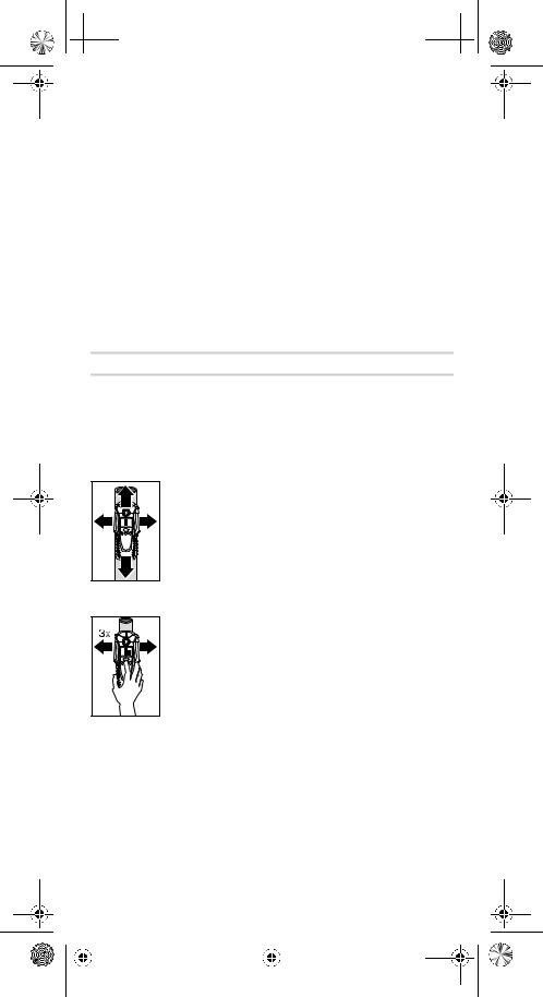
 OBJ_BUCH-1 609 929 J68-001.book Page 3 Monday, January 30, 2006 11:20 AM
Para conectar el aparato de medida pulsar una tecla cualquiera.
Al conectar el aparato de medida con la tecla para detección de madera 5 o con la tecla para detección de metal 6 se selecciona directamente también la función de exploración respectiva.
Si el aparato de medida es conectado con la tecla de conexión/desconexión 7 o con la tecla “ZOOM” 4, se activa la función de exploración utilizada la última vez.
Una vez concluida la breve rutina de autocontrol del aparato de medida, éste se encuentra en disposición de funcionamiento. Si el aparato de medida se encuentra en la función para detección de metales, la disponibilidad de funcionamiento se indica representándose un ganchito al lado del indicador de calibrado “AutoCal” g.
Para desconectar el aparato de medida pulsar la tecla de conexión/desconexión 7.
En caso de no activarse ninguna tecla del aparato de medida durante aprox. 5 min, el aparato de medida se desconecta automáticamente para evitar una descarga innecesaria de la pila.
Modos de operación
El aparato de medida detecta los objetos situados debajo del área del sensor 9.
Detección de objetos metálicos
Si desea localizar objetos metálicos, pulse la tecla para detección de metales 6. En el display se representa el símbolo c para la detección de metales, además de iluminarse de color verde el anillo 1.
Asiente el aparato de medida sobre la superficie a explorar y desplácelo lateralmente. Al aproximarse el aparato a un objeto metálico, la amplitud en el indicador de medida f aumenta, y ésta vuelve a disminuir al distanciarse del objeto. Al alcanzarse el punto de máxima deflexión, el objeto metálico está situado justo debajo del centro del sensor (debajo del orificio para marcado 2). Si el aparato de medida se mantiene posicionado sobre el objeto metálico, el anillo 1 permanece iluminado de color rojo y además se emite una señal acústica permanente.
Para localizar con mayor exactitud el objeto, pulse la tecla “Zoom” 4 y manténgala accionada mientras pasa repetidamente con el aparato de medida por encima del objeto (3 veces). En el display se representa el símbolo de la función zoom d. En la posición correspondiente al centro del objeto metálico se obtiene la deflexión máxima en el indicador zoom e.
Si desea detectar objetos metálicos muy pequeños o profundos y no se obtiene una señal en el indicador de medida f, pulse entonces, y mantenga en esa posición, la tecla “ZOOM” 4 al sobrepasar el área. Al realizar la exploración solamente centre su atención en el indicador de medida zoom e.
Si el material que está explorando albergase inclusiones metálicas, en el indicador de medida f se representa entonces continuamente una señal. Pulse entonces la tecla “ZOOM” 4 y manténgala presionada a sobrepasar el área. Al realizar la exploración solamente centre su atención en el indicador de medida zoom e.
|
1 609 929 J68 • 30.1.06 |
Español–3 |
|||||
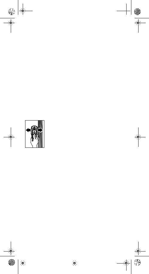
OBJ_BUCH-1 609 929 J68-001.book Page 4 Monday, January 30, 2006 11:20 AM 
Si el objeto metálico detectado fuese un metal magnético (p.ej. hierro), se muestra entonces el símbolo h en el display. En metales no magnéticos se representa el símbolo i. Para discernir entre los diversos tipos de metal deberá situarse el aparato de medida sobre el objeto metálico detectado (el anillo 1 se enciende de color rojo). Si la señal es demasiado débil no es posible determinar el tipo de metal detectado.
Si el material de base explorado contiene en su interior malla o varilla de acero se obtiene continuamente una señal en el indicador de medida f. En estos casos emplee siempre la función zoom. Al explorar áreas que contengan malla de acero se suele observar en el display el símbolo h para metales magnéticos al encontrarse el aparato directamente sobre la varilla de acero, y el símbolo para metales no magnéticos i al estar situado entre las varillas.
Detección de objetos de madera
Para localizar objetos de madera pulse la tecla para detección de madera 5. En el display se muestra el símbolo b para detección de madera y el indicador de la función zoom d, además de parpadear la flecha situada debajo del indicador de la función zoom d. El indicador de calibrado “AutoCal” g y el anillo 1 se apagan.
Deposite el aparato de medida sobre la superficie a explorar. Pulse entonces la tecla “ZOOM” 4 y manténgala pulsada. El anillo luminoso 1 se enciende entonces de color verde, se vuelve a representar el indicador de calibrado “AutoCal” g, y se apagan el indicador de la función zoom d y la flecha situada debajo.
Desplace uniformemente el aparato de medida sobre la superficie, sin separarlo y sin variar la presión de aplicación, manteniendo pulsada la tecla “ZOOM” 4. Durante la medición deberá observarse que las protecciones de fieltro 8 queden en contacto permanente con la base.
En caso de detectar un objeto de madera se obtiene una señal en el indicador de medida f. Desplace repetidamente el aparato de medida sobre la superficie para loca-
lizar con mayor exactitud el objeto de madera. Sobrepasando varias veces el mismo área puede localizarse el objeto de madera con gran exactitud. Siempre que el aparato de medida se encuentre encima del objeto de madera se enciende el anillo 1 de color rojo y se emite una señal acústica permanente. La amplitud máxima en el indicador de medida f se alcanza en el centro del objeto de madera. El indicador de medida zoom e no se activa al detectar objetos de madera.
Atención: si casualmente deposita el aparato de medida en un punto debajo del cual se encuentre un objeto de madera y desplaza el aparato sobre la superficie que pretende explorar, entonces parpadea el indicador de medida f y la flecha debajo del indicador zoom d, y el anillo luminoso 1 parpadea en color rojo. En este caso realice la medición de nuevo, colocando el aparato de medida en una posición desfasada de la anterior y pulse nuevamente la tecla “ZOOM” 4.
Al tratar de localizar objetos de madera puede ocurrir que los objetos detectados sean en realidad objetos metálicos situados a una profundidad entre 20–50 mm. Para saber si los objetos encontrados son de madera o metal, seleccionar la función para detección de metales (ver “Detección de objetos metálicos”). Si con esta función se detecta un objeto en el mismo punto, ello indica que el objeto localizado es de metal y no de madera. Para continuar buscando objetos de madera seleccione nuevamente la función para detección de madera.
|
1 609 929 J68 • 30.1.06 |
Español–4 |
|||||
OBJ_BUCH-1 609 929 J68-001.book Page 5 Monday, January 30, 2006 11:20 AM 
Detección de conductores portadores de tensión
El aparato de medición detecta conductores con una tensión entre 110 V y 400 V con una frecuencia (tensión alterna de 50 ó 60 Hz) de uso muy generalizado. Los demás conductores (de corriente continua, frecuencias y tensiones mayores o menores) solamente son detectados como objetos metálicos.
Los conductores portadores de tensión que pudieran existir se muestran tanto en la función de búsqueda de metales como en la función de búsqueda de madera. En caso de detectarse un conductor portador de tensión se representa entonces en el display el indicador a. Desplace repetidamente el aparato de medida sobre la superficie para poder detectar con mayor exactitud el conductor eléctrico. Después de haber sobrepasado reiteradamente por encima del conductor portador de tensión, la localización de éste puede realizarse de forma muy exacta. Si el aparato de medida se encuentra muy próximo al conductor (amplitud de cuatro o cinco escalones en el indicador a), comienza a parpadear en color rojo el anillo luminoso 1 y la señal acústica se emite muy seguidamente.
Los conductores portadores de tensión pueden detectarse más fácilmente si se conecta a ellos, y se deja funcionar, algún consumidor (p.ej. una lámpara o aparato). Los conductores con tensiones de 110 V, 230 V y 400 V (corriente trifásica) se detectan sin apreciarse gran diferencia entre ellos.
Bajo ciertas condiciones (p.ej. detrás de superficies metálicas o de aquellas con mucha humedad) puede que no se detecten con fiabilidad los conductores portadores de tensión. Para identificar estas áreas puede recurrirse a la función para detección de metal. Si dentro de un área relativamente amplia se obtiene una señal f en cada punto, ello indica que el material apantalla las señales eléctricas, lo que no permite detectar con fiabilidad conductores portadores de tensión.
Los cables que no sean portadores de tensión pueden detectarse como objeto metálico con la función para detección de metales. Sin embargo, no son detectados los cables flexibles con alma de hilos múltiples (a diferencia de los cables rígidos de alma maciza).
Instrucciones para la operación
BCondicionado por el principio de funcionamiento, los resultados de medición pueden verse afectados por ciertas condiciones del entorno. Éstas pueden ser p.ej. la proximidad de aparatos que generen unos fuertes campos magnéticos o electromagnéticos, la humedad, materiales de construcción que contengan metal, y materiales aislantes revestidos con lámina de aluminio o papeles pintados conductores. Por ello, antes de taladrar, serrar o fresar en paredes, techos o suelos, recomendamos consultar otras fuentes de información (p.ej. planos de construcción).
Desconexión de la señal acústica
Ud. puede activar y desactivar la señal acústica. Para ello pulse simultáneamente las teclas para detección de metal 6 y madera 5. Si se ha desactivado la señal acústica se representa en el display el símbolo j.
La modalidad elegida para la señal acústica se mantiene también tras la desconexión del aparato de medida.
Marcado de los objetos
Si lo desea puede marcar también la posición de los objetos detectados. Para ello retire el lápiz 11 del aparato de medida y efectúe la medida en la manera acostumbrada. Una vez localizados los límites o el centro del objeto, marque el punto correspondiente por el orificio de marcado 2.
|
1 609 929 J68 • 30.1.06 |
Español–5 |
|||||
OBJ_BUCH-1 609 929 J68-001.book Page 6 Monday, January 30, 2006 11:20 AM 
Indicador “AutoCal”
Si el ganchito al margen del indicador de calibrado “AutoCal” g no fuese perceptible durante largo tiempo o desapareciese del todo, no es posible entonces realizar mediciones fiables. En estos casos entregue el aparato de medida a un servicio técnico autorizado Bosch. Excepción: en la función para detección de madera desaparece el indicador de autocalibrado “AutoCal” g, siempre que no se pulse la tecla “ZOOM” 4.
Mantenimiento y servicio
Mantenimiento y limpieza
Si el indicador de medida f muestra permanentemente un valor, a pesar de no encontrarse cerca del aparato de medida ningún objeto de metal, es posible recalibrar manualmente el aparato de medida. Retirar para ello todos los objetos que se encuentren cerca del aparato de medida (también un reloj de pulsera o anillo de metal) y sujete el aparato de medida en el aire. Estando desconectado el aparato de medida, pulse al mismo tiempo la tecla de conexión/desconexión 7 y la tecla para detección de madera 5 hasta que el anillo luminoso 1. Suelte entonces ambas teclas. Si el calibrado fue correcto, pasados algunos segundos, se conecta nuevamente el aparato de medida que queda así en disposición de funcionamiento.
Limpie el aparato con un paño seco y suave. No utilice agentes de limpieza ni disolvente.
Para no falsear la medición no deberán fijarse en el área del sensor 9 tanto en el frente como al dorso del aparato de medida ni etiquetas ni placas, especialmente si éstas fuesen de metal.
No desprenda las protecciones de fieltro 8 al dorso del aparato de medida. Sustituya las protecciones de fieltro si estuviesen dañadas o desgastadas. Desprenda completamente las protecciones de fieltro y pegue las protecciones nuevas en el mismo lugar.
Solamente guarde y transporte el aparato de medida en el estuche de protección adjunto.
Si a pesar de los esmerados procesos de fabricación y control, el aparato de medida llegase a averiarse, la reparación deberá encargarse a un taller de servicio autorizado para herramientas eléctricas Bosch.
Al realizar consultas o solicitar piezas de repuesto, es imprescindible indicar siempre el nº de artículo de 10 dígitos que figura en la placa de características del aparato de medida.
Piezas de repuesto
|
Estuche de protección . . . . . . . . . . . . . . . . . . . . . . . . . . . . |
1 609 203 P19 |
Tapa del alojamiento de la pila 10 . . . . . . . . . . . . . . . . . . . . 1 609 203 R32
Protección de fieltro 8 . . . . . . . . . . . . . . . . . . . . . . . . . . . . . 1 609 203 P21
|
1 609 929 J68 • 30.1.06 |
Español–6 |
|||||
 Loading…
Table of Contents for Bosch PDO Multi:
-
Deutsch–6 1 609 929 J68 • 30.1.06 Wartung und Service Wartung und Reinigung Schlägt die Messanzeige f dauerhaft aus, obwohl sich kein Objekt aus Metall in der Nähe des Messwerkzeugs befindet, kann das Messwerkzeug manuell kalibriert werden. Entfernen Sie dazu alle Objekte aus der Nähe des Messwerkzeugs (auch Armbanduhr oder Ring aus Metall) und halten Sie das Messwerkzeug in die Luft. Drücken Sie bei ausgeschaltetem Messwerkzeug die Ein-Aus-Taste 7 und die Taste für Holzsuche 5 so lange gleichzeitig, bis der Leuchtring 1 gleichzeitig rot und grün leuchtet.
-
Português–3 1 609 929 J68 • 30.1.06 Colocação em funcionamento Proteger o instrumento de medição contra humidade ou insolação directa. Ligar e desligar B Antes de ligar o instrumento de medição, deverá assegurar-se de que a área do sensor 9 não esteja húmida. Se necessário, deverá secar o instrumento de medição com um pano. B Se o instrumento de medição foi exposto a uma extrema mudança de temperatura, deverá permitir
-
Eλληνικά–7 1 609 929 J68 • 30.1.06 Συντήρηση και Service Συντήρηση και καθαρισµς Αν η ένδειξη µέτρησησ f αποκλίνει συνεχώσ, παρ’ λο που κοντά στο εργαλείο µέτρησησ δεν υπάρχει κάποιο µεταλλικ αντικείµενο, ττε µπορείτε να καλιµπράρετε την τιµή µέτρησησ µε το χέρι. Γι’ αυτ πρέπει �
-
Norsk–6 1 609 929 J68 • 30.1.06 Reservedeler Beskyttelsesveske . . . . . . . . . . . . . . . . . . . . . . . . . . . . . . . . 1 609 203 P19 Deksel til batterirom 10. . . . . . . . . . . . . . . . . . . . . . . . . . . . . 1 609 203 R32 Filt 8 . . . . . . . . . . . . . . . . . . . . . . . . . . . . . . . . . . . . . . . . . . . . 1 609 203 P21 Service og kunderådgiver Eksplosjonstegninger og informasjoner om reservedeler finner du under: www.bosch-pt.com
-
Eλληνικά–1 1 609 929 J68 • 30.1.06 Περιγραφή λειτουργίας Η άριστη εργασία µε το εργαλείο µέτρησης είναι µνο δυνατή, ταν διαβάσετε πρώτα καλά λες τις οδηγίες χειρισµού και τις υποδείξεις εργασίας και τηρείτ�
-
Deutsch–2 1 609 929 J68 • 30.1.06 Technische Daten Betrieb Batterien einsetzen/wechseln Verwenden Sie ausschließlich Alkali-Mangan-Batterien oder Akkus. Zum Öffnen des Batteriefachdeckels 10 drücken Sie die Arretierung 12 in Pfeilrichtung und klappen den Batteriefachdeckel hoch. Setzen Sie die mit- gelieferte Batterie ein. Achten Sie dabei auf die richtige Polung entspre- chend der Darstellung auf der Innenseite des Ba
-
Svenska–6 1 609 929 J68 • 30.1.06 Reservdelar Skyddsfodral . . . . . . . . . . . . . . . . . . . . . . . . . . . . . . . . . . . . . 1 609 203 P19 Batterifackets lock 10. . . . . . . . . . . . . . . . . . . . . . . . . . . . . . 1 609 203 R32 Filtglidstycken 8. . . . . . . . . . . . . . . . . . . . . . . . . . . . . . . . . . . 1 609 203 P21 Service och kundrådgivare Sprängskissar och information om reservdelar lä
-
Español–4 1 609 929 J68 • 30.1.06 Si el objeto metálico detectado fuese un metal magnético (p.ej. hierro), se muestra entonces el símbolo h en el display. En metales no magnéticos se representa el símbolo i. Para discernir entre los diversos tipos de metal deberá situarse el aparato de medida sobre el objeto metálico detectado (el anillo 1 se enciende de color rojo). Si la señal es demasiado débil no es posible determinar el tipo de metal detectado. Si el material de base explorado contiene en su interior malla o varilla de acero
-
Français–4 1 609 929 J68 • 30.1.06 Si des treillis soudés ou des armatures se trouvent derrière la surface exa- minée, des oscillations sont affichées sur l’ensemble de la surface de l’affi- chage de mesure f. Dans un tel cas, toujours utiliser la fonction Zoom pour la détection. Généralement, lors de la détection de treillis soudés, le sym- bole h pour métaux magnétiques apparaît sur l’affichage direc
-
Türkçe–4 1 609 929 J68 • 30.1.06 Ahşap nesnelerin taranması (aranması) Ahşap nesneleri taramak için ahşap arama 5 tuşuna basın. Display’de ahşap arama sembolü b ve d Zoom fonksiyonu göstergesi gösterilir, Zoom göstergesi d altındaki ok yanar söner. Kalibrasyon göstergesi “AutoCal” g ve ışıkılı halka 1 söner. Tarama cihazını tarama yapacağınız yüzeye yerleştirin. Ancak ondan sonra “ZOOM” tuşuna 4 basın ve bu tuşu basılı tutun. Işıklı halka 1 yeşil olarak yanar, ka
-
日本語–3 1 609 929 J68 • 30.1.06 メジャーリングツールの電源を 入れる には、いずれかのボタンを押して ください。 メジャーリングツールの木材探知用ボタン 5 または金属探知用ボタン 6 を 押すと、それぞれの探知モードに移ります。 メジャーリングツールのオン / オフスイッチ 7 または 『ZOOM モード』 ボ タン 4 で電源を入れた場合、ツールは前回使用した�
-
Eλληνικά–6 1 609 929 J68 • 30.1.06 Υπ ορισµένεσ συνθήκεσ (π.χ. πίσω απ µεταλλικέσ ή υγρέσ επιφάνειεσ) οι ηλεκτροφροι αγωγοί δεν µπορούν να εντοπιστούν ασφαλώσ. Οι περιοχέσ αυτέσ εντοπίζονται στην Αναζητηση µετάλλων. Σε περίπτωση που σε µια σχετικά µεγάλη περιοχή εµφανίζεται παντού µια τιµή
Questions, Opinions and Exploitation Impressions:
You can ask a question, express your opinion or share our experience of Bosch PDO Multi device using right now.