- Manuals
- Brands
- SUZUKI Manuals
- Outboard Motor
- DF 50
Manuals and User Guides for SUZUKI DF 50. We have 2 SUZUKI DF 50 manuals available for free PDF download: Service Manual, Supplemental Service Manual

Suzuki DF 50 Service Manual (405 pages)
Four Stroke
Brand: Suzuki
|
Category: Outboard Motor
|
Size: 10.42 MB
Table of Contents
-
General Information 1
5
-
Component Parts and Important Item Illustrations
3
-
Table of Contents
5
-
Warning/Caution/Note
6
-
General Precautions
6
-
General Information
6
-
-
Identification Number Location
8
-
Fuel and Oil
8
-
Gasoline Recommendation
8
-
Engine Oil
8
-
-
Engine Break-In
9
-
Propellers
10
-
Specifications
11
-
Service Data
13
-
General Information
15
-
Starter Motor
18
-
Self-Diagnostic System Indication
19
-
-
Tightening Torque
20
-
Special Tools
22
-
Materials Required
25
-
-
Periodic Maintenance 2
26
-
Periodic Maintenance Schedule
27
-
Periodic Maintenance Chart
27
-
-
Maintenance and Tune-Up Procedures
28
-
Engine Oil / Engine Oil Filter
28
-
Engine Oil Change/Engine Oil Filterreplacement
29
-
Gear Oil
31
-
Lubrication
32
-
Spark Plug
33
-
Tappet Clearance
34
-
Idle Speed
40
-
Ignition Timing
41
-
Breather and Fuel Line
42
-
Low Pressure Fuel Filter
42
-
High Pressure Fuel Filter
43
-
Water Pump / Water Pump Impeller
43
-
Propeller / Nut / Cotter Pin
43
-
Anodes and Bonding Wires
44
-
Battery
45
-
Bolt and Nuts
46
-
Fuel Mixture Check (Ofeedback)
47
-
-
Oil Pressure
52
-
Cylinder Compression
54
-
-
Engine Control System
55
-
Engine Control System Structure
56
-
System Structure 1
56
-
System Structure 2
57
-
Wiring Diagram for Engine Control
58
-
Engine Control System
58
-
-
Components for System Control
59
-
Engine Control Module (Ecm)
59
-
Ecm Connectors / Terminals Layout
60
-
Ecm Internal Structure
61
-
Sensor and Switch
62
-
-
Ignition System
66
-
Ignition Control System
66
-
-
Electronic Fuel Injection System
68
-
Fuel Injection Control System
68
-
Fuel Delivery System Components
70
-
Fuel Pump Control System
73
-
Air Intake Components
74
-
Idle Air Control System Outline
75
-
-
Caution System
77
-
Over-Revolution Caution System
77
-
Low Oil Pressure Caution System
78
-
Overheat Caution
79
-
Electrical
80
-
Low Battery Voltage Caution System
80
-
-
Self-Diagnostic System
81
-
Priority / Code / Pattern for Self-Diagnostic System Operation
81
-
Condition for Self-Diagnostic System Operation
83
-
-
Fail-Safe System
84
-
Pre-Programmed Value for Fail-Safe System
84
-
-
Operating Hour Indication System
85
-
Start-In-Gear Protection System
86
-
O 2 Feedback System
87
-
Inspection
88
-
Precaution on System Inspection
88
-
Inspection for Ecm Circuit Voltage
88
-
Inspection for Resistance
90
-
Other Inspection
91
-
-
Troubleshooting
96
-
Fuel System
96
-
-
Removal / Installation
102
-
Flywheel / Ckp Sensor / Cmp Sensor
102
-
Oil Pressure Switch
105
-
-
-
Electrical
106
-
Battery Charging System
107
-
Outline
107
-
Removal / Installation
110
-
-
Electric Starter System
112
-
Outline
112
-
Troubleshooting
113
-
Inspection
114
-
Starting Motor
117
-
-
Monitor-Tachometer
123
-
Inspection
123
-
-
-
Fuel System
124
-
Precaution on Fuel System Service
125
-
General Precaution
125
-
Fuel Pressure Relief Procedure
126
-
-
Fuel Line
127
-
Removal / Installation
127
-
Fuel Leakage Check Procedure
127
-
Fuel Hose Connection
128
-
Fuel Pressure Inspection
129
-
-
Fuel Vapor Separator / High Pressure Fuel Pump
131
-
Removal / Installation
131
-
Disassembly
132
-
Inspection
133
-
Assembly
135
-
-
Fuel Injector
136
-
Inspection
136
-
Removal
136
-
Installation
137
-
-
Low Pressure Fuel Pump
138
-
Removal / Installation
138
-
Disassembly / Reassembly
139
-
Inspection
140
-
-
Fuel Tank
141
-
Disassembly / Reassembly
141
-
-
Inspection
142
-
-
Power Unit
143
-
Intake Manifold Assembly
144
-
Removal
144
-
Installation
145
-
-
Power Unit
146
-
Removal
146
-
Installation
150
-
-
Oil Pump / Case
153
-
Removal
153
-
Disassembly
153
-
Inspection
154
-
Measuring Pump Components
154
-
Assembly
155
-
Installation
155
-
-
Timing Chain / Tensioner
158
-
Removal
158
-
Inspection
160
-
Installation
161
-
-
Cylinder Head Assembly
164
-
Removal
164
-
Assembly
164
-
Disassembly
167
-
Inspection / Servicing
168
-
Reassembly
181
-
-
Cylinder / Crankshaft / Piston
183
-
Disassembly
183
-
Inspection / Servicing
186
-
Reassembly
200
-
-
Thermostat
207
-
Operation
208
-
Water Cooling System
208
-
Engine Lubrication System
209
-
-
-
Power Trim and Tilt
210
-
System Wiring Diagram
211
-
Service Procedure
212
-
Oil Level
212
-
Air Bleeding
212
-
-
Power Trim and Tilt Unit
213
-
Removal
213
-
Disassembly
214
-
Cleaning and Inspecting
216
-
Reassembly
218
-
Ptt Motor
220
-
Installation
224
-
-
Ptt Motor Relay
226
-
Ptt Switch
227
-
Operation
228
-
Components
228
-
Principles of Operation
229
-
-
-
Lower Unit
234
-
Removal & Disassembly
235
-
Pinion Bearing
239
-
Inspection
241
-
Propeller
241
-
Gearcase
241
-
Gear
242
-
Propeller Shaft Components
242
-
Propeller Shaft Bearing Housing
242
-
Shift Rod and Shift Cam
243
-
Water Pump and Related Items
243
-
Driveshaft Bearing Housing
244
-
Driveshaft
245
-
-
Assembly & Installation
246
-
Trim Tab
256
-
Lower Unit Gears-Shimming and Adjustment
257
-
Wiring Diagram
263
-
Fuel / Water Hose Routing
269
-
-
-
Df40150 «K5» (2005) Model .
273
-
Specifications (Df50Wtidf50Wqh)
274
-
Service Data
278
-
Tightening Torque
285
-
Flywheel MAGNETO and CRANKSHAFT
286
-
Over-Revolution Caution System
286
-
Safety Relay System
286
-
Battery Charging System
287
-
Electric Starter System
289
-
Assembly
303
-
Remote Control Box & Remote Control Wire
306
-
Cylinder Head
307
-
Upper Oil Seal Housing
307
-
Upper Mount
308
-
Lower Mount
309
-
Clamp Bracket Shaft
310
-
Ptt Motor Relay
311
-
Swivel Bracket Bush
311
-
Tiller Handle Assy
311
-
Driveshaftidriveshaft Bearing Housing
313
-
Gearcase Magnet
314
-
Shift Rod Guide
314
-
Water Pump Case
314
-
Propeller Shaft Bearing
315
-
Wiring Diagram
316
-
-
Df40/50 «K6» (2006) Model
326
-
Specifications (Df40T/Df40Qh/Df50T/Df50Th)
327
-
Specifications (Df50Wt/Df50Wqh)
329
-
Service Data
331
-
Periodic Maintenance Schedule
338
-
Ecm
339
-
Fuel Filter
339
-
Iac Hose
339
-
Intake Manifold
340
-
Piston
341
-
Water Pump Case under Gasket
341
-
Wiring Diagram
342
-
Fuel Hose Routing
345
-
-
Df40/50 «K7» (2007) Model
348
-
Specifications (Df40T/Df40Qh/Df50T/Df50Th)
349
-
Specifications (Df50Wt/Df50Wqh)
351
-
Service Data
353
-
Tightening Torque
360
-
Periodic Maintenance Schedule
361
-
Ecm
362
-
Silencer
362
-
Tiller Handle (Df40Qh, Df50Qh and Df50Wqh)
363
-
Clutch Dog Shifter and Return Spring
365
-
Clutch Shaft Arm and Clutch Shaft Side Arm
365
-
Detent Spring and Shift Cam
365
-
Engine Side Cover
366
-
-
Forward
370
-
General Information
372
-
Warning/Caution/Note
372
-
General Precautions
372
-
-
Specifications
374
-
Lower Unit
375
-
-
Service Data
376
-
Tightening Torque
382
-
Special Tools
384
-
Materials Required
387
-
Wiring Diagram
388
-
Engine Control System
389
-
Caution / Diagnostic System
389
-
Engine Speed Control During Shifting
390
-
Checking Engine Total Operating Hours
390
-
-
MID Unit
391
-
Tiller Handle
391
-
Removal
391
-
Disassembly
392
-
Assembly
395
-
Installation
396
-
-
Tilt Aid System
401
-
Removal
401
-
Inspection
402
-
Installation
403
-
-
-
Advertisement

Suzuki DF 50 Supplemental Service Manual (20 pages)
Brand: Suzuki
|
Category: Outboard Motor
|
Size: 0.59 MB
Table of Contents
-
Table of Contents
2
-
Specifications
3
-
Service Data
5
-
Ecm Main Relay
10
-
Exhaust Manifold Temperature Sensor and Cylinder Temperature Sensor
10
-
Cylinder Block
11
-
Buzzer
11
-
Neutral Switch Bracket
12
-
Under Oil Seal Housing
12
-
Forward Gear Thrust Washer
12
-
Exhaust Cam Shaft
13
-
Wiring Diagrams
14
-
Wire Routing
15
Advertisement
Related Products
-
Suzuki DF5A
-
Suzuki DF50A
-
Suzuki DF50AV
-
Suzuki DF15
-
Suzuki DF200
-
Suzuki DF90A
-
Suzuki DF 140 Four Stroke
-
Suzuki DF6A
-
Suzuki DF115WT
-
Suzuki DF150A
SUZUKI Categories
Motorcycle
Automobile
Motorcycle Accessories
Musical Instrument
Offroad Vehicle
More SUZUKI Manuals

99500-87J00-01E
FOREWORD
This manual contains an introductory description on
SUZUKI Outboard motor DF40/50 and procedures
for the inspection, service and overhaul of its main
components.
General knowledge information is not included.
Please read the GENERAL INFORMATION section to familiarize yourself with basic information
concerning this motor. Read and refer to the other
sections in this manual for information regarding proper inspection and service procedures.
This manual will help you better understand this outboard motor so that you may provide your customers with optimum and quick service.
• This manual has been prepared using the latest information available at the time of publication.
If a modification has been made since then,
differences may exist between the content of
this manual and the actual outboard motor.
• Illustrations in this manual are used to show
the basic principles of operation and work procedures and may not represent the actual
outboard motor in exact detail.
• This manual is intended for use by technicians
who already possess the basic knowledge and
skills to service SUZUKI outboard motors.
Persons without such knowledge and skills
should not attempt to service an outboard
engine by relying on this manual only.
Instead, please contact your nearby authorized SUZUKI outboard motor dealer.
GROUP INDEX
GENERAL INFORMATION
1
PERIODIC MAINTENANCE
2
ENGINE CONTROL SYSTEM
3
ELECTRICAL
4
FUEL SYSTEM
5
POWER UNIT
6
MID UNIT
7
POWER TRIM AND TILT
8
LOWER UNIT
9
WIRE / HOSE ROUTING
A
Apprentice machanics or do-it-yourself mechanics that don’t have the proper tools and
equipment may not be able to properly perform the services described in this manual.
Improper repair may result in injury to the
mechanic and may render the engine unsafe
for the boat operator and passengers.
Marine & Power Products Division
COPYRIGHT SUZUKI MOTOR CORPORATION 1998
10
HOW TO USE THIS MANUAL
TO LOCATE WHAT YOU ARE
LOOKING FOR:
1. The text of this manual is divided into sections.
2. The section titles are listed on the previous page
in a GROUP INDEX. Select the section you wish
to reference.
3. Holding the manual as shown at the right will allow you to find the first page of the section easily.
4. The first page of each section lists a table of contents to easily locate the item and page you need.
COMPONENT PARTS AND IMPORTANT ITEM ILLUSTRATIONS
Under the name of each system or unit, an exploded view is provided with work instructions and other
service information such as the tightening torque, lubrication and locking agent points.
Example :
@ 200 N.m
(20.0 kg-m, 145 lb.-ft.)
1 Flywheel bolt
2 Washer
3 Key
4 Flywheel
5 CKP sensor
6 Screw
7 CMP sensor
8 Bolt
1
o
2
3
4
5
5
6
h
5
Crankshaft
7
8
NOTE:
Clean flywheel and crankshaft mating
surfaces with cleaning solvent.
SYMBOL
Listed in the table below are the symbols indicating instructions and other important information necessary for proper servicing. Please note the definition for each symbol. You will find these symbols used
throughout this manual. Refer back to this table if you are not sure of any symbol(s) meanings.
SYMBOL
DEFINITION
SYMBOL
@
Torque control required.
Data beside it indicates specified
torque.
h
Apply THREAD LOCK “1342”.
g
Apply THREAD LOCK SUPER
o
j
v
Apply oil. Use engine oil unless
otherwise specified.
Apply SUZUKI OUTBOARD
MOTOR GEAR OIL.
Apply SUZUKI SUPER GREASE “A”.
l
Apply SUZUKI WATER
a
Apply SUZUKI BOND “1104”.
b
Apply SUZUKI BOND “1207B”.
k
Apply SUZUKI SILICONE SEAL.
RESISTANT GREASE.
DEFINITION
“1333B”.
s
Measure in DC voltage range.
t
Measure in resistance range.
r
Measure in continuity test range.
q
z
Use peak voltmeter
“Stevens CD-77”.
Use special tool.
GENERAL INFORMATION
1
CONTENTS
WARNING/CAUTION/NOTE _________________________________
GENERAL PRECAUTIONS _________________________________
IDENTIFICATION NUMBER LOCATION _______________________
FUEL AND OIL ___________________________________________
1-1
1-1
1-3
1-3
GASOLINE RECOMMENDATION ................................................................. 1-3
ENGINE OIL ................................................................................................... 1-3
ENGINE BREAK-IN _______________________________________ 1-4
PROPELLERS ___________________________________________ 1-5
SPECIFICATIONS _________________________________________ 1-6
SERVICE DATA ___________________________________________ 1-8
TIGHTENING TORQUE ____________________________________ 1-15
SPECIAL TOOLS _________________________________________ 1-17
MATERIALS REQUIRED ___________________________________ 1-20
1-1 GENERAL INFORMATION
WARNING/CAUTION/NOTE
Please read this manual and follow its instructions carefully. To emphasize special information, the symbol and the words WARNING, CAUTION and NOTE have special meanings. Pay special attention to the
messages highlighted by these signal words.
A
Indicates a potential hazard that could result in death or injury.
B
Indicates a potential hazard that could result in motor damage.
NOTE:
Indicates special information to make maintenance easier or instructions clearer.
Please note, however, that the warnings and cautions contained in this manual cannot possibly cover all
potential hazards relating to the servicing, or lack of servicing, of the outboard motor. In addition to the
WARNING and CAUTION stated, you must also use good judgement and observe basic mechanical
safety principles.
GENERAL PRECAUTIONS
A
• Proper service and repair procedures are important for the safety of the service mechanic
and the safety and reliability of the outboard motor.
• To avoid eye injury, always wear protective goggles when filing metals, working on a grinder,
or doing other work, which could cause flying material particles.
• When 2 or more persons work together, pay attention to the safety of each other.
• When it is necessary to run the outboard motor indoors, make sure that exhaust gas is
vented outdoors.
• When testing an outboard motor in the water and on a boat, ensure that the necessary
safety equipment is on board. Such equipment includes : flotation aids for each person, fire
extinguisher, distress signals, anchor, paddles, bilge pump, first-aid kit, emergency starter
rope, etc.
• When working with toxic or flammable materials, make sure that the area you work in is
well-ventilated and that you follow all of the material manufacturer’s instructions.
• Never use gasoline as a cleaning solvent.
• To avoid getting burned, do not touch the engine, engine oil or exhaust system during or
shortly after engine operation.
• Oil can be hazardous. Children and pets may be harmed from contact with oil. Keep new
and used oil away from children and pets. To minimize your exposure to oil, wear a long
sleeve shirt and moisture-proof gloves (such as dishwashing gloves) when changing oil. If
oil contacts your skin, wash thoroughly with soap and water. Launder any clothing or rags
if wet with oil. Recycle or properly dispose of used oil.
• After servicing fuel, oil/engine cooling system and exhaust system, check all lines and
fittings related to the system for leaks.
• Carefully adhere to the battery handling instructions laid out by the battery supplier.
GENERAL INFORMATION
1-2
B
• If parts replacement is necessary, replace the parts with Suzuki Genuine Parts or their
equivalent.
• When removing parts that are to be reused, keep them arranged in an orderly manner so
that they may be reinstalled in the proper order and orientation.
• Be sure to use special tools when instructed.
• Make sure that all parts used in assembly are clean and also lubricated when specified.
• When use of a certain type of lubricant, bond, or sealant is specified, be sure to use the
specified type.
• When removing the battery, disconnect the negative cable first and then the positive cable.
When reconnecting the battery, connect the positive cable first and then the negative cable.
• When performing service to electrical parts, if the service procedures do not require using
battery power, disconnect the negative cable at the battery.
• Tighten cylinder head and case bolts and nuts, beginning with larger diameter and ending
with smaller diameter, Always tighten from inside to outside diagonally, to the specified
tightening torque.
• Whenever you remove oil seals, gaskets, packing, O-rings, locking washers, locking nuts,
cotter pins, circlips, and certain other parts as specified, always replace them with new.
Also, before installing these new parts, be sure to remove any left over material from the
mating surfaces.
• Never reuse a circlip. When installing a new circlip, take care not to expand the end gap
larger than required to slip the circlip over the shaft. After installing a circlip, always ensure that it is completely seated in its groove and securely fitted.
• Use a torque wrench to tighten fasteners to the torque values when specified.
Remove grease or oil from screw / bolt threads unless a lubricant is specified.
• After assembly, check parts for tightness and operation.
• To protect the environment, do not unlawfully dispose of used motor oil, other fluids, and
batteries.
• To protect the Earth’s natural resources, properly dispose of used motor parts.
1-3 GENERAL INFORMATION
IDENTIFICATION NUMBER LOCATION
MODEL PRE-FIX SERIAL NUMBER
The MODEL, PRE-FIX and SERIAL NUMBER of motor are
stamped on a plate attached to the clamp bracket.
Example
MODEL
DF 50
05001F–XXXXXX
PRE-FIX
SERIAL NUMBER
ENGINE SERIAL NUMBER
A second engine serial number plate is pressed into a boss
on the cylinder block .
FUEL AND OIL
GASOLINE RECOMMENDATION
Suzuki highly recommends that you use alcohol - free unleaded gasoline with a minimum pump octane rating of 87
(R+M / 2 method) or 91 (Research method). However, blends
of unleaded gasoline and alcohol with equivalent octane content may be used.
Allowable maximum blend of a single additive (not combination) :
5% Methanol, 10% Ethanol, 15% MTBE
B
If leaded gasoline is used, engine damage may result.
ENGINE OIL
Use only oils that are rated SE, SF, SG, SH, or SJ under the
API (American Petroleum Institute) classification system.
The viscosity rating should be SAE 10W-40.
If an SAE 10W-40 motor oil is not available, select an alternative according to the chart at right.
GENERAL INFORMATION
ENGINE BREAK-IN
The first 10 hours are critically important to ensure correct
running of either a brand new motor or a motor that has been
reconditioned or rebuilt. How the motor is operated during this
time will have direct bearing on its life span and long-term
durability.
Break-in period : 10 hours
WARM-UP RECOMMENDATION
Allow sufficient idling time (more than 5 minutes) for the engine to warm up after cold engine starting .
THROTTLE RECOMMENDATION
NOTE:
Avoid maintaining a constant engine speed for an extended
period at any time during the engine break-in by varying the
throttle position occasionally.
1. FIRST 2 HOURS
For first 15 minutes, operate the engine in-gear at idling
speed.
During the remaining 1 hour and 45 minutes, operate the
engine in-gear at less than 1/2 (half) throttle (3000 r/min).
NOTE:
The throttle may be briefly opened beyond the recommended
setting to plane the boat, but must be reduced to the recommended setting immediately after planning.
2. NEXT 1 HOUR
Operate the engine in-gear at less than 3/4 (three-quarter) throttle (4000 r/min).
3. LAST 7 HOURS
Operate the engine in-gear at desired engine speed.
However, do not operate continuously at full throttle for
more than 5 minutes.
1-4
1-5 GENERAL INFORMATION
PROPELLERS
An outboard motor is designed to develop its rated power
within a specified engine speed range. The maximum rated
power delivered by the DF40 / 50 T models is shown below.
Recommended full
throttle speed range
DF40T
5200-5800 r / min
DF50T
5900-6500 r / min
If the standard propeller fails to meet the above requirement,
use another pitch propeller to hold the engine speed within
the range specified above.
Propeller selection chart
Blade
3
3
3
3
3
3
3
3
3
×
×
×
×
×
×
×
×
×
×
Diam. (in.)
11- 1/2
11- 1/2
11- 1/2
11- 5/8
11- 1/2
11- 3/8
11- 1/4
11- 1/8
11
×
×
×
×
×
×
×
×
×
×
Pitch (in.)
9 (S900)
10 (S1000)
11 (S1100)
12 (S1200)
13 (S1301, SS1300)
14 (S1400, SS1400)
15 (S1500)
16 (S1600, SS1600)
17 (S1700)
GENERAL INFORMATION
SPECIFICATIONS
Item
Unit
PRE-FIX
Data
DF40T
DF50T
04001F
05001F
DIMENSIONS & WEIGHT
Overall length (front to back)
mm (in.)
756 (29.8)
Overall width (side to side)
mm (in.)
382 (15.0)
Overall height
S
mm (in.)
1263 (49.7)
L
mm (in.)
1390 (54.7)
S
kg (Ib.)
106 (234)
L
kg (Ib.)
109 (240)
S
mm (in. type)
401 (15)
L
mm (in. type)
528 (20)
Weight
(without engine oil)
Transom height
PERFORMANCE
kW (PS)
29.4 (40)
36.8 (50)
Recommended operating range
r/min
5200 – 5800
5900 – 6500
Idle speed
r/min
Maximum output
850 ± 50 (in-gear: approx. 850±50)
POWERHEAD
Engine type
4-stroke DOHC
Number of cylinders
3
Bore
mm (in.)
71.0 (2.80)
Stroke
mm (in.)
68.6 (2.70)
3
Total displacement
cm (cu in.)
815 (49.7)
Compression ratio
:1
10
NGK
DCPR6E
Spark plug
Ignition system
Fuel supply system
Full-transistorized ignition
Multi-point sequential electronic fuel injection
Exhaust system
Through prop exhaust
Cooling system
Water cooled
Lubrication system
Wet sump by trochoid pump
Starting system
Electric
Throttle control
Remote control
1-6
1-7 GENERAL INFORMATION
Item
Unit
Data
DF40T
DF50T
FUEL & OIL
Suzuki highly recommends that you use alcohol-free unleaded gasoline
with a minimum pump octane rating of 87 ( R +2 M method) or 91
(Research method). However, blends of unleaded gasoline and alcohol
with equivalent octane content may be used.
Fuel
Engine oil
API classification
SE, SF, SG, SH, SJ
Viscosity rating 10W-40
Engine oil amounts
2.2 (2.3/1.9) : Oil change only
L (US/Imp. qt)
2.4 (2.5/2.1) : Oil filter change
Gear oil
Gearcase oil capacity
SUZUKI Outboard Motor Gear Oil (SAE #90 hypoid gear oil)
ml (US/Imp. oz)
610 (20.6/21.5)
BRACKET
Trim angle
PTT system
Number of trim position
PTT system
Maximum tilt angle
degree
73°
LOWER UNIT
Reversing system
Gear
Transmission
Forward-Neutral-Reverse
Reduction system
Bevel gear
Gear ratio
11 : 25 (2.27)
Drive line impact protection
Propeller
Spline drive rubber hub
Blade × Diam. (in.) × Pitch (in.)
S : Aluminum propeller
SS : Stainless steel propeller
These specifications are subject to change without notice.
3
3
×
×
11-1/2
11-1/2
× 9 (S900)
× 10 (S1000)
3
3
×
×
11-1/2
11-5/8
× 11 (S1100)
× 12 (S1200)
3
3
×
×
11-1/2
11-3/8
× 13 (S1301, SS1300)
× 14 (S1400, SS1400)
3
3
×
×
11-1/4
11-1/8
× 15 (S1500)
× 16 (S1600, SS1600)
3
×
11
× 17 (S1700)
GENERAL INFORMATION
SERVICE DATA
Item
Data
Unit
DF40T
DF50T
5200 – 5800
5900 – 6500
POWERHEAD
Recommended operating range
r/min
Idle speed
r/min
**Cylinder compression
**Cylinder compression max.
difference between any two
cylinders
**Engine oil pressure
850 ± 50 (in-gear: approx.850±50)
kPa (kg/cm2. psi)
kPa (kg/cm . psi)
100 (1.0, 14)
kPa (kg/cm2. psi)
Engine oil
Engine oil amounts
1300 – 1600 (13 – 16, 185 – 228)
2
295 – 373 (3.0 – 3.8, 42 – 54) at 4000 r/min
(at normal operating temp.)
API classification
SE, SF, SG, SH, SJ
Viscosity rating
SAE 10W-40
2.2 (2.3/1.9) : Oil change only
L (US/Imp. qt)
2.4 (2.5/2.1) : Oil filter change
Thermostat operating
temperature
°C (°F)
** Figures shown are guidelines only, not absolute service limits.
48 – 52 (126 – 134)
1-8
1-9 GENERAL INFORMATION
Item
Unit
Data
DF40T
DF50T
ENGINE OIL PUMP
Radial clearance
Limit
mm (in.)
0.31 (0.0122 in.)
Side clearance
Limit
mm (in.)
0.15 (0.0059 in.)
CYLINDER HEAD / CAMSHAFT
Cylinder head distortion
Limit
mm (in.)
0.05 (0.002)
Manifold seating
faces distortion
Limit
mm (in.)
0.10 (0.004)
STD
mm (in.)
37.530–37.690 (1.4776–1.4839)
38.230–38.390 (1.5051–1.5114)
Limit
mm (in.)
37.430 (1.4736)
38.130 (1.5012)
STD
mm (in.)
37.740–37.900 (1.4858–1.4921)
37.740–37.900 (1.4858–1.4921)
Limit
mm (in.)
37.640 (1.4819)
37.640 (1.4819)
STD
mm (in.)
0.045 – 0.087 (0.0018 – 0.0034)
Limit
mm (in.)
0.12 (0.0047)
STD
mm (in.)
23.000 – 23.021 (0.9055 – 0.9063)
Limit
mm (in.)
23.171 (0.9122)
STD
mm (in.)
22.934 – 22.955 (0.9029 – 0.9037)
Limit
mm (in.)
22.784 (0.8970)
Camshaft runout
Limit
mm (in.)
0.10 (0.004)
Cylinder head bore
to tappet clearance
STD
mm (in.)
0.025 – 0.062 (0.0010 – 0.0024)
Limit
mm (in.)
0.150 (0.0059)
Tappet outer
diameter
STD
mm (in.)
26.959 – 26.975 (1.0614 – 1.0620)
Cylinder head bore
STD
mm (in.)
27.000 – 27.021 (1.0630 – 1.0638)
Cam height
IN
EX
Camshaft journal oil
clearance
Top,
Camshaft
2nd,
journal
(housing)
3rd,
inside diameter
4th
Top,
Camshaft
2nd,
journal outside
3rd,
diameter
4th
GENERAL INFORMATION
Item
Unit
Data
DF40T
DF50T
VALVE / VALVE GUIDE
Valve diameter
Tappet clearance IN
(Cold engine
EX
condition)
Valve seat
angle
IN
mm (in.)
24.6 (0.9685)
EX
mm (in.)
21.5 (0.8465)
STD
mm (in.)
0.18 – 0.24 (0.007 – 0.009)
STD
mm (in.)
0.18 – 0.24 (0.007 – 0.009)
IN
30°, 45°
EX
15°, 45°
STD
mm (in.)
0.020 – 0.047 (0.0008 – 0.0019)
Limit
mm (in.)
0.070 (0.0028)
STD
mm (in.)
0.045 – 0.072 (0.0018 – 0.0028)
Limit
mm (in.)
0.090 (0.0035)
Valve guide inside
IN,EX
diameter
STD
mm (in.)
5.500 – 5.512 (0.2165 – 0.2170)
Valve guide
protrusion
IN,EX
STD
mm (in.)
11 (0.4331)
IN
STD
mm (in.)
5.465 – 5.480 (0.2152 – 0.2157)
EX
STD
mm (in.)
5.440 – 5.455 (0.2142 – 0.2148)
IN,EX
Limit
mm (in.)
3.2 (0.1260)
IN
Limit
mm (in.)
0.14 (0.0055)
EX
Limit
mm (in.)
0.18 (0.0071)
Valve stem runout IN,EX
Limit
mm (in.)
0.05 (0.0020)
Valve head radial
IN,EX
runout
Limit
mm (in.)
0.08 (0.0031)
STD
mm (in.)
1.0 (0.0394)
Limit
mm (in.)
0.7 (0.0276)
STD
mm (in.)
1.15 (0.0453)
Limit
mm (in.)
0.5 (0.0197)
IN
STD
mm (in.)
1.80 – 2.20 (0.0709 – 0.0866)
EX
STD
mm (in.)
1.65 – 2.05 (0.0650 – 0.0984)
Valve guide to
valve stem
clearance
IN
EX
Valve stem
outside diameter
Valve stem end
length
Valve stem end
deflection
Valve head
thickness
IN
EX
Valve seat
contact width
Valve spring free
length
STD
mm (in.)
33.13 (1.3043)
Limit
mm (in.)
31.80 (1.2520)
Valve spring tension
STD
N (kg, Ibs)
95 – 111 (9.7–11.3, 21.4–24.9) for 28.5 mm (1.12 in.)
Limit
N (kg, Ibs)
88 (8.9, 19.6) for 28.5 mm (1.12 in.)
Limit
mm (in.)
2.0 (0.079)
Valve spring
sequareness
1-10
1-11 GENERAL INFORMATION
Item
Unit
Data
DF40T
DF50T
CYLINDER / PISTON / PISTON RING
Cylinder distortion
Limit
mm (in.)
0.06 (0.0024)
Piston to cylinder
clearance
STD
mm (in.)
0.020 – 0.040 (0.0008 – 0.0016)
Limit
mm (in.)
0.100 (0.0039)
Cylinder bore
STD
mm (in.)
71.000 – 71.020 (2.7953 – 2.7961)
mm (in.)
50 (1.969) from cylinder top surface
mm (in.)
70.970 – 70.990 (2.7941 – 2.7949)
mm (in.)
19 (0.748) from piston skirt end.
Limit
mm (in.)
0.10 (0.039)
STD
mm (in.)
0.10 – 0.25 (0.0039 – 0.0098)
Limit
mm (in.)
0.70 (0.0276)
STD
mm (in)
0.25 – 0.40 (0.0098 – 0.0157)
Limit
mm (in.)
1.00 (0.0394)
STD
mm (in.)
Approx. 7.5 (0.2953)
Limit
mm (in.)
6 (0.2362)
STD
mm (in.)
Approx. 11 (0.4330)
Limit
mm (in.)
8.8 (0.3465)
STD
mm (in.)
0.020 – 0.060 (0.0008 – 0.0024)
Limit
mm (in.)
0.10 (0.0039)
STD
mm (in.)
0.020 – 0.060 (0.0008 – 0.0024)
Limit
mm (in.)
0.10 (0.0039)
1st
STD
mm (in.)
1.01 – 1.03 (0.0398 – 0.0406)
2nd
STD
mm (in.)
1.01 – 1.03 (0.0398 – 0.0406)
Oil
STD
mm (in.)
1.51 – 1.53 (0.0594 – 0.0602)
1st
STD
mm (in.)
0.97 – 0.99 (0.0382 – 0.0390)
2nd
STD
mm (in.)
0.97 – 0.99 (0.0382 – 0.0390)
STD
mm (in.)
0.006 – 0.018 (0.0002 – 0.0007)
Limit
mm (in.)
0.040 (0.0016)
STD
mm (in.)
17.966 – 18.000 (0.7085 – 0.7087)
Limit
mm (in.)
17.980 (0.7079)
STD
mm (in.)
18.006 – 18.014 (0.7089 – 0.7092)
Limit
mm (in.)
18.040 (0.7102)
STD
mm (in.)
0.003 – 0.015 (0.0001 – 0.0006)
Limit
mm (in.)
0.05 (0.002)
STD
mm (in.)
18.003 – 18.011 (0.7088 – 0.7091)
Cylinder measuring position
Piston skirt diameter
STD
Piston measuring position
Cylinder bore wear
Piston ring
end gap
1st
2nd
Piston ring
free end gap
1st
2nd
Piston ring to
groove
clearance
1st
2nd
Piston ring
groove width
Piston ring
thickness
Pin clearance in
piston pin hole
Piston pin outside
diameter
Piston pin hole
diameter
Pin clearance in
conrod small end
Conrod small end
bore
GENERAL INFORMATION
Item
Unit
Data
DF40T
DF50T
CRANKSHAFT / CONROD
Conrod small end
inside diameter
STD
mm (in.)
18.003 – 18.011 (0.7088 – 0.7091)
Conrod big end oil
clearance
STD
mm (in.)
0.020 – 0.040 (0.0008 – 0.0016)
Limit
mm (in.)
0.065 (0.0026)
Conrod big end
inside diameter
STD
mm (in.)
41.000 – 41.018 (1.6142 – 1.6149)
Crank pin outside
diameter
STD
mm (in.)
37.982 – 38.000 (1.4954 – 1.4961)
Crank pin outside
diameter difference
(out of round and taper)
Limit
mm (in.)
0.010 (0.0004)
Conrod bearing
thickness
STD
mm (in.)
1.486 – 1.502 (0.0585 – 0.0591)
Conrod big end side
clearance
STD
mm (in.)
0.100 – 0.250 (0.0039 – 0.0098)
Limit
mm (in.)
0.350 (0.0138)
Conrod big end width
STD
mm (in.)
21.950 – 22.000 (0.8642 – 0.8661)
Crank pin width
STD
mm (in.)
22.100 – 22.200 (0.8700 – 0.8740)
Crankshaft center
journal runout
Limit
mm (in.)
0.04 (0.0016)
Crankshaft journal
oil clearance
STD
mm (in.)
0.020 – 0.040 (0.0008 – 0.0016)
Limit
mm (in.)
0.065 (0.0026)
Crankcase bearing
holder inside diameter
STD
mm (in.)
49.000 – 49.018 (1.9291 – 1.9298)
Crankshaft journal
outside diameter
STD
mm (in.)
44.982 – 45.000 (1.7709 – 1.7717)
Limit
mm (in.)
0.01 (0.0004)
STD
mm (in.)
1.999 – 2.015 (0.0787 – 0.0793)
Crankshaft journal
outside diameter
difference
(out of round and taper)
Crankshaft bearing
thickness
Crankshaft thrust
play
STD
mm (in.)
0.11 – 0.31 (0.0043 – 0.0122)
Limit
mm (in.)
0.35 (0.0138)
Crankshaft thrust
bearing thickness
STD
mm (in.)
2.470 – 2.520 (0.0972 – 0.0992)
1-12
1-13 GENERAL INFORMATION
Item
Unit
Data
DF40T
DF50T
Degrees at r/min
BTDC 0° – BTDC 32°
BTDC 0° – BTDC 25°
r/min
6500
7000
ELECTRICAL
Ignition timing
Over revolution limiter
CKP sensor resistance
W at 20°C
168 – 252
CMP sensor resistance
W at 20°C
——
Ignition coil resistance Primary
W at 20°C
1.9 – 2.5
k W at 20°C
8.1 – 11.1
W at 20°C
0.56 – 0.84
Watt
216
Type
NGK
DCPR 6E
Gap
mm (in.)
0.9 – 1.0 (0.035 – 0.039)
A
Main fuse
: 30
Fuel pump fuse : 15
Ah (kC)
70 (252) or larger
Fuel injector resistance
W at 20°C
11.0 – 16.5
IAC valve resistance
W at 20°C
21.5 – 32.3
k W at 25°C
1.8 – 2.3
ECM main relay resistance
W at 20°C
80 – 120
Starter motor relay resistance
W at 20°C
3.5 – 5.1
PTT motor relay resistance
W at 20°C
3.0 – 4.5
Max. continuous time of use
Sec
30
Motor output
kW
0.9
STD
mm (in.)
17.0 (0.67)
Limit
mm (in.)
10.0 (0.39)
STD
mm (in.)
0.5 – 0.8 (0.02 – 0.03)
Limit
mm (in.)
0.2 (0.008)
STD
mm (in.)
33.0 (1.30)
Limit
mm (in.)
32.0 (1.26)
Secondary
Battery charge coil resistance
Battery charge coil output (12V)
Standard spark plug
Fuse amp. rating
Recommended battery
capacity (12V)
IAT sensor/Cylinder temp. sensor
/ Ex-mani. temp. sensor
(Thermistor characteristic)
STARTER MOTOR
Brush length
Commutator
undercut
Commutator
outside diameter
Commutator outside
diameter difference
STD
mm (in.)
0.05 (0.002)
Limit
mm (in.)
0.40 (0.016)
Pinion to ring gear gap
STD
mm (in.)
3.0 – 5.0 (0.12 – 0.20)
GENERAL INFORMATION
1-14
PTT MOTOR
Brush length
Commutator outside
diameter
STD
mm (in.)
9.8 (0.39)
Limit
mm (in.)
4.8 (0.19)
STD
mm (in.)
22.0 (0.87)
Limit
mm (in.)
21.0 (0.83)
SELF-DIAGNOSTIC SYSTEM INDICATION
When the abnormality occurs in a signal from sensor, switch etc., the “CHECK ENGINE” lamp on the
monitor-tachometer flashes (lights intermittently) according to the each code pattern with buzzer sounding.
PRIORITY
*
FAILED ITEM
CODE
1
MAP sensor 1
3–4
2
CKP sensor
4–2
3
IAC valve/By-pass air
screw adjustment
3–1
4
CMP sensor
2–4
5
CTP switch
2–2
6
Cylinder temp. sensor
1–4
7
IAT sensor
2–3
8
MAP sensor 2
(Sensor hose)
3–2
9
Rectifier & regulator
(Over-charging)
1–1
10
Exhaust manifold temp.
sensor
1–5
LAMP FLASHING PATTERN
on
off
on
off
on
off
on
off
on
off
on
off
on
off
on
off
on
off
on
off
FAIL-SAFE SYSTEM
ACTIVE
YES
NO
NO
YES
NO
YES
YES
NO
NO
YES
* If more than two items fail at once, the self-diagnostic indication appears according to priority order.
The indication repeats three times.
1-15 GENERAL INFORMATION
TIGHTENING TORQUE
Tightening Torque – Important Fasteners
THREAD
DIAMETER
ITEM
TIGHTENING TORQUE
.
N m
kg-m
Ib.-ft.
Cylinder head cover bolt
6 mm
10
1.0
7.2
Cylinder head bolt
10 mm
59
6.0
43.4
Crankcase bolt
8 mm
25
2.5
18.1
10 mm
53
5.3
38.3
8 mm
35
3.5
25.3
Camshaft housing bolt
10
1.0
7.2
Camshaft timing sprocket bolt
10
1.0
7.2
Timing chain guide bolt
10
1.0
7.2
6 mm
11
1.1
7.9
8 mm
23
2.3
16.5
13
1.3
9.5
10
1.0
7.2
35
3.5
25.3
Conrod cap nut
Intake manifold bolt / nut
Oil pressure switch
Intake manifold fuel main gallery
3-way joint bolt
6 mm
Upper/lower plug
Low pressure fuel pump bolt
6 mm
10
1.0
7.0
Thermostat cover bolt
6 mm
10
1.0
7.0
Flywheel bolt
16 mm
200
20.0
145
Starter motor mounting bolt
8 mm
23
2.3
16.5
14
1.4
10.0
Engine oil filter
Engine oil drain plug
12 mm
13
1.3
9.5
Power unit mounting bolt/nut
8 mm
23
2.3
16.5
10 mm
50
5.0
36.0
Driveshaft housing bolt
10 mm
50
5.0
36.0
Upper mount nut
10 mm
40
4.0
30.0
Upper mount cover bolt
8 mm
23
2.3
16.6
Front
12 mm
60
6.0
43.5
Rear
12 mm
40
4.0
29.0
Clamp bracket shaft nut
22 mm
43
4.3
31.0
Water pump case nut
6 mm
8
0.8
5.8
Gearcase bolt
8 mm
23
2.3
16.6
Propeller shaft bearing housing bolt
8 mm
17
1.7
12.3
50
5.0
36.2
55
5.5
40.0
Lower mount nut
Pinion nut
Propeller nut
18 mm
GENERAL INFORMATION
1-16
Tightening torque – general bolt
NOTE:
These values are only applicable when torque for a general bolt is not listed in the “Important Fasteners”
table.
TYPE OF BOLT
(Conventional or “4” marked bolt)
(Stainless steel bolt)
(7 marked or
marked bolt)
TIGHTENING TORQUE
THREAD
DIAMETER
N.m
kg-m
Ib.-ft.
5 mm
2–4
0.2 – 0.4
1.5 – 3.0
6 mm
4–7
0.4 – 0.7
3.0 – 5.0
8 mm
10 – 16
1.0 – 1.6
7.0 – 11.5
10 mm
22 – 35
2.3 – 3.5
16.0 – 25.5
5 mm
2–4
0.2 – 0.4
1.5 – 3.0
6 mm
6 – 10
0.6 – 1.0
4.5 – 7.0
8 mm
15 – 20
1.5 – 2.0
11.0 – 14.5
10 mm
34 – 41
3.4 – 4.1
24.5 – 29.5
5 mm
3–6
0.3 – 0.6
2.0 – 4.5
6 mm
8 – 12
0.8 – 1.2
6.0 – 8.5
8 mm
18 – 28
1.8 – 2.8
13.0 – 20.0
10 mm
40 – 60
4.0 – 6.0
29.0 – 43.5
1-17 GENERAL INFORMATION
SPECIAL TOOLS
1.
2.
3.
4.
09821-00004
Air pump Assy
09900-00410
Hexagon wrench set
09900-00411
Hexagon socket
(included in 09900-00410)
09900-00413 (5 mm)
09900-00414 (6 mm)
Hexagon bit
(included in 09900-00410)
5.
6.
7.
8.
(A) 09900-06107
(B) 09900-06108
Snap ring pliers
09900-20101 (150 mm)
09900-20102 (200 mm)
Vernier calipers
09900-20202
Micrometer (25 – 50 mm)
09900-20203
Micrometer (50 – 75 mm)
9.
10.
11.
12.
09900-20205
Micrometer (0 – 25 mm)
09900-20508
Cylinder gauge set
(40 – 80 mm)
09900-20605
Dial calipers (10 – 34 mm)
09900-20606
Dial gauge
13.
14.
15.
16.
(A)
(B)
09900-20701
Magnetic stand
09900-20803
Thickness gauge
09900-21304
Steel “V” block set
09900-22302
(0.051 – 0.125 mm)
09900-22301
(0.025 – 0.076 mm)
Plastigauge
17.
18.
19.
20.
09900-26006
Engine tachometer
09900-28403
Hydrometer
09921-29510
Driveshaft holder
09919-16010
Deep socket wrench
22.
23.
09913-50121
Oil seal remover
09914-79410
Test wheel
21.
(3)
(1)
(1) 09912-58441
Fuel pressure gauge
(2) 09912-58431
Fuel pressure hose
(3) 09912-58490
3-way joint & hose
(2)
GENERAL INFORMATION
1-18
24.
25.
26.
27.
09915-47340
Oil filter wrench
09915-64510
Compression gauge
09915-63210
Adaptor
09915-77310
Oil pressure gauge
09915-78211
Oil pressure gauge adapter
28.
29.
30.
31.
09916-10910
Valve lapper
09916-14510
Valve lifter
09916-14910
Valve lifter attachment
09916-24450
Solid pilot (N-100-5.52)
32.
33.
34.
35.
09916-24440
Handle adaptor
(N-503-1)
09916-24980
Handle (N-503)
09916-20630
Valve seat cutter
(Neway 126)
09916-20620
Valve seat cutter
(Neway 122)
36.
37.
38.
39.
09916-20610
Valve seat cutter
(Neway 121)
09916-34550
Valve guide reamer
f 5.5 mm)
(f
09916-34542
Valve guide reamer handle
09916-37320
Valve guide reamer
f 10.5 mm)
(f
40.
41.
42.
43.
09916-44310
Valve guide remover
09916-57330
Valve guide installer
09916-67010
Tappet holder
09916-77310
Piston ring compressor
44.
45.
46.
47.
09917-87010
Valve guide installer
attachment
(A) 09922-59410
Propeller shaft housing
installer
(B) 09922-59420
Housing installer handle
09916-84511
Tweezers
09917-47910
Vacuum pump gauge
(A)
(B)
1-19 GENERAL INFORMATION
48.
49.
50.
51.
09922-89810
Shift lock pin remover
09930-30161
Propeller shaft remover
09930-30102
Sliding hammer
09930-39411
Flywheel rotor remover
52.
53.
54.
55.
09930-39420
Rotor remover bolt
09930-48720
Flywheel holder
09930-76420
Timing light
09930-89240
4-pin connector test cord
56.
57.
58.
59.
09930-89260
Injector test cord A
09930-89910
4-pin connector test cord
09930-89920
6-pin connector test cord
09930-89930
8-pin connector test cord
60.
61.
62.
63.
09930-89940
12-pin connector test cord
09930-99320
Digital tester
09932-79910
Diagnostic harness
09940-44120
Air pressure gauge
64.
65.
66.
67.
(A)
09940-44130
Attachment
68.
09944-08711
PTT cylinder cap tool
(B)
(D)
(A)
(C)
Pinion bearing
installer and remover
(A) 09951-59910
Pinion bearing installer
shaft
(B) 01107-08408
Bolt
(C) 09951-39914
Pinion bearing plate
(D) 09951-19430
Attachment
(B)
(A) 09950-69511
Gearcase oil leakage tester
(B) 09821-00004
Air pump
09951-09510
Gear adjusting gauge
69.
70.
(A)
(B)
(A) 18213-74F00
O2 sensor
(B) 18498-99E40
Protector
09930-88720
H.T cord adapter
GENERAL INFORMATION
71.
72.
73 .
99954-53008-820*
Digital voltmeter
99954-53873*
Stevens CD-77
Peak reading voltmeter
99954-53883*
Gear oil filler
1-20
NOTE:
* Marked part No. is in U.S. market only.
MATERIALS REQUIRED
SUZUKI OUTBOARD
MOTOR GEAR OIL
SUZUKI SUPER
GREASE “A”
WATER RESISTANT
GREASE
SUZUKI SILICONE
SEAL
99000-22540
(400 ml × 24 pcs.)
*99000-25030
99000-25010
(500 g)
99000-25160
(250 g)
99000-31120
(50 g)
SUZUKI BOND “1104”
SUZUKI BOND “1207B”
THREAD LOCK “1342”
4-Stroke Motor Oil
99000-31030
(100 g)
* 99104-33140
99000-31140
(100 g)
99000-32050
(50 g)
API : SE, SF, SG, SH, SJ
SAE : 10W-40
NOTE:
* Marked part No. is in U.S. market only.
PERIODIC MAINTENANCE
CONTENTS
PERIODIC MAINTENANCE SCHEDULE _______________________ 2-1
PERIODIC MAINTENANCE CHART .............................................................. 2-1
MAINTENANCE AND TUNE-UP PROCEDURES _________________ 2-2
ENGINE OIL / ENGINE OIL FILTER ............................................................... 2-2
GEAR OIL ........................................................................................................ 2-5
LUBRICATION ................................................................................................. 2-6
SPARK PLUG .................................................................................................. 2-7
TAPPET CLEARANCE .................................................................................... 2-8
IDLE SPEED .................................................................................................... 2-14
IGNITION TIMING ............................................................................................ 2-15
BREATHER AND FUEL LINE ......................................................................... 2-16
LOW PRESSURE FUEL FILTER .................................................................... 2-16
HIGH PRESSURE FUEL FILTER.................................................................... 2-17
WATER PUMP / WATER PUMP IMPELLER ................................................... 2-17
PROPELLER / NUT / COTTER PIN ................................................................ 2-17
ANODES AND BONDING WIRES .................................................................. 2-18
BATTERY ......................................................................................................... 2-19
BOLT AND NUTS ............................................................................................ 2-20
FUEL MIXTURE CHECK (O2 FEEDBACK) .................................................... 2-21
OIL PRESSURE ___________________________________________ 2-26
CYLINDER COMPRESSION _________________________________ 2-28
2
2-1 PERIODIC MAINTENANCE
PERIODIC MAINTENANCE SCHEDULE
The chart below lists the recommended intervals for all the required periodic service work necessary to keep
the motor operating at peak performance and economy.
Maintenance intervals should be judged by number of hours or months, whichever comes first.
NOTE:
More frequent servicing should be performed on outboard motors that are used under severe conditions.
PERIODIC MAINTENANCE CHART
Interval
Item to be serviced
Spark plug
Breather Hose & Fuel line
Initial 20 hrs.
or 1 month
Every 50 hrs.
or 3 months
Every 100 hrs.
or 6 months
Every 200 hrs.
or 12 months
—
—
I
R
I
I
I
I
Replace every 2 years
Engine oil
R
—
R
R
Gear oil
R
—
R
R
Lubrication
—
I
I
I
Anodes & Bonding wires
—
I
I
I
Battery
—
I
I
I
Fuel mixture check
(O2 feedback)
Engine oil filter
Perform every 2 years.
R
—
—
Low pressure fuel filter
Replace every 400 hours or 2 years.
High pressure fuel filter
Replace every 1000 hours.
Ignition timing
R
—
—
—
I
Idle Speed
I
—
—
I
Tappet clearance
I
—
—
I
Water pump
—
—
—
I
Water pump impeller
—
—
—
R
Propeller nut & pin
I
—
I
I
Bolt & Nuts
T
—
T
T
I : Inspect and clean, adjust, lubricate, or replace, if necessary
T : Tighten R : Replace
PERIODIC MAINTENANCE 2-2
MAINTENANCE AND TUNE-UP PROCEDURES
This section describes the servicing procedures for each of the
periodic maintenance requirements.
ENGINE OIL / ENGINE OIL FILTER
ENGINE OIL LEVEL CHECK
Inspect oil level before every use.
(1) Place the outboard motor upright on a level surface.
2
(2) Remove the motor cover.
(3) Remove the oil level dipstick and wipe it clean.
(4) Insert it fully into the dipstick hole, then remove it to check
oil level.
1Oil level dipstick
2Oil filler cap
1
(5) Oil level should be between the full level line (Max.) and
low level line (Min.)
If the level is low, add recommended oil to full level line.
Recommended oil :
• 4 stroke motor oil
• API classification SE, SF, SG, SH, SJ.
• Viscosity rating
SAE 10 W-40.
Full level
line
Low level
line
2-3 PERIODIC MAINTENANCE
ENGINE OIL CHANGE / ENGINE OIL FILTER
REPLACEMENT
ENGINE OIL
Change initially after 20 hours (1 month) and every
100 hours (6 months) thereafter.
ENGINE OIL FILTER
Replace initially after 20 hours (1 month) and every
200 hours (12 months) thereafter.
NOTE:
• Engine oil should be changed while the engine is warm.
• When replacing the engine oil filter, change engine oil at the
same time.
1
1. Place the outboard motor upright on a level surface.
2. Remove the oil filler cap.
1Oil filler cap
3. Place a container under the engine oil drain plug.
4. Remove the engine oil drain plug and gasket to drain engine oil.
1
1Oil drain plug
5. ENGINE OIL FILTER REPLACEMENT
NOTE:
For engine oil change only, go to step 6.
To replace the engine oil filter :
(1) Remove the PORT side lower cover. (See page 7-1)
(2) Using oil filter wrench, loosen the oil filter.
z 09915-47340 : Oil filter wrench
NOTE:
Before fitting new oil filter, be sure to oil O-ring.
o
2
2Gasket
PERIODIC MAINTENANCE 2-4
(3) Screw new filter on by hand until the filter O-ring contacts the Mounting surface.
(4) Tighten the filter 3/4 turn from the point of contact with
the mounting surface using an oil filter wrench.
@ Engine oil filter : 14 N . m (1.4 kg-m, 10.0 lb.-ft.),
3/4 turn.
(5) Install the PORT side lower cover.
6. Install the gasket and the oil drain plug.
Tighten the engine oil drain plug to the specified torque.
@ Engine oil drain plug : 13N . m (1.3 kg-m, 9.5 lb.-ft.)
B
Do not re-use gasket. Always replace with a new gasket.
7. Pour recommended engine oil into the oil filler opening, then
install the oil filler cap.
Engine oil amounts
Oil change only : 2.2L (2.3 / 1.9 US / Imp. qt)
Oil filter change : 2.4L (2.5 / 2.1 US / Imp. qt)
8. Start the engine and allow it to run for several minutes at
idle speed.
Check oil filter for oil leakage.
Turn off the engine and wait for approx. two minutes, then
re-check the engine oil level.
Full level
line
Low level
line
2-5 PERIODIC MAINTENANCE
GEAR OIL
Change initially after 20 hours (1 month) and every 100
hours (6 months) thereafter.
(1) Place the outboard motor upright on a level surface.
(2) Place a container under the lower unit.
(3) Remove the lower gear oil drain plug before the gear oil
level plug and drain the gear oil.
1
2
1 Oil level plug
2 Oil drain plug
(4) Fill with the recommended gear oil through the oil drain hole
until oil just starts to flow out from the oil level hole.
Gear oil amount : 610 ml ( 20.6 / 21.5 US / Imp. oz)
Recommended oil :
Suzuki Outboard Motor Gear Oil or SAE # 90
Hypoid gear oil
(5) Install the oil level plug before removing the oil filler tube
from the drain hole.
(6) Install the oil drain plug.
B
Do not re-use gaskets. Always use a new gasket.
PERIODIC MAINTENANCE 2-6
LUBRICATION
Inspect every 50 hours (3 months).
Apply Suzuki Water Resistant Grease to the following points.
l 99000-25160 : Water Resistant Grease
Throttle/Shift linkage
Swivel bracket
Steering bracket
Propeller shaft
2-7 PERIODIC MAINTENANCE
SPARK PLUG
• Inspect every 100 hours (6 months).
• Replace every 200 hours (12 months).
Standard spark plug : NGK DCPR6E
CARBON DEPOSIT
Check for a carbon deposit on the spark plug bases.
If carbon is present, remove it with a spark plug cleaning machine or by carefully using a pointed tool.
SPARK PLUG GAP
Use a thickness gauge to measure for correct spark plug gap.
Adjust to within the specified range if the gap is out of specification.
Spark plug gap : 0.9 – 1.0 mm (0.035 – 0.039 in.)
z 09900-20803 : Thickness gauge
CONDITION OF ELECTRODE
Check the electrode for a worn or burnt condition.
If it is extremely worn or burnt, replace the spark plug.
Also, be sure to replace the plug if it has a broken insulator,
damaged thread, etc.
Gap
B
Confirm the thread size and reach when replacing the
plug. If the reach is too short, carbon will be deposited
on the threaded portion of the plug hole resulting in
possible engine damage.
@ Spark plug : 17.5 N . m (1.75 kg-m, 12.7 lb.-ft.)
PERIODIC MAINTENANCE 2-8
TAPPET CLEARANCE
Inspect initially after 20 hours (1 month) and every 200
hours (12 months) thereafter
The tappet clearance specification is the same for both intake
and exhaust valves.
Too small a tappet clearance may reduce engine power, too
large a tappet clearance increases valve noise and hastens
valve and seat wear.
When the tappets are set to the specified clearance, the engine
will run without excessive noise from the valve mechanism and
will deliver full power. In this engine, the tappet clearance is
increased or decreased by replacing the shim disc, made of a
special wear resistant material, fitted to the top of the tappet.
The shim discs are easy to remove and refit.
Tappet clearance adjustment must be checked and adjusted:
• at the time of periodic inspection
• when the valve mechanism is serviced
• when the camshafts are disturbed by removing them for inspection
CHECKING AND ADJUSTING TAPPET CLEARANCE
(1) Remove following parts :
• Engine side lower cover (see page 7-1)
• Flywheel cover
• Ignition coils
• Spark plugs
(2) Disconnect camshaft sensor lead 1.
(3) Remove fuel hose (intake and outlet)2.3 from low fuel
pump.
(4) Remove the twelve bolts securing the cylinder head cover
4 to the cylinder head and remove cylinder head cover.
8
3
9
1
4
6
2
7
5
11
10
12
2-9 PERIODIC MAINTENANCE
(5) Rotate crankshaft clockwise to bring cam nose vertical to
shim surface.
90°
(6) Measure tappet clearances by inserting thickness gauge
between cam and shim surface.
Tappet clearance (cold engine condition) :
IN. : 0.18 – 0.24 mm (0.007 – 0.009 in.)
EX. : 0.18 – 0.24 mm (0.007 – 0.009 in.)
z 09900-20803 : Thickness gauge
B
Rotate crankshaft clockwise to prevent water pump
impeller damage.
NOTE:
• Rotate crankshaft and measure clearance for each tappet
respectively by bringing cam nose vertical to shim surface.
• All tappet clearances can be measured during two turns of
crankshaft.
(7) If out of specification, adjust tappet clearance by changing
shim.
z
PERIODIC MAINTENANCE 2-10
ADJUSTMENT
Tappet clearances are adjusted by replacing tappet shim.
(1) Close valve and turn tappet cut-away toward inside as shown
in figure.
2
3 1
1 Cut section of tappet
2 Plug hole
3 Shim
(2) Rotate crankshaft to open (lift up) the valve and then remove camshaft housing bolts where the shim to be replaced.
(3) Install special tool with camshaft housing bolts as shown in
figure.
1
2
z
z 09916-67010 : Tappet holder
1 Camshaft housing bolt
2 Plug hole
NOTE:
Index mark “IN” on the tappet holder is for intake side, while
“EX” is for exhaust side.
1
(4) Rotate top of cam 90 degree clockwise and remove shim
from cut-away at tappet.
(Two tappets can be adjusted at the same time)
B
• Do not put your finger between camshaft and tappet
while the tappet is being held with the tappet holder.
• Use a magnet to remove and install shim.
• When installing shim, identification mark on the shim
must face towards tappet side.
(5) After removing shim, measure thickness of original shim and
determine correct thickness of shim for proper tappet clearance as calculated by the following formula.
2
1 Magnet
2 Shim
1
z 09900-20205 : Micrometer
A = B + (C – 0.20 mm)
1 Removed shim
A : Correct thickness of shim for proper tappet
clearance (mm)
B : Thickness of original shim (mm)
C : Original tappet clearance (mm)
2-11 PERIODIC MAINTENANCE
I.D No.
Thickness
(mm)
I.D No.
Thickness
(mm)
I.D No.
Thickness
(mm)
218
2.18
246
2.46
274
2.74
220
2.20
248
2.48
276
2.76
222
2.22
250
2.50
278
2.78
224
2.24
252
2.52
280
2.80
226
2.26
254
2.54
282
2.82
228
2.28
256
2.56
284
2.84
230
2.30
258
2.58
286
2.86
232
2.32
260
2.60
288
2.88
234
2.34
262
2.62
290
2.90
236
2.36
264
2.64
292
2.92
238
2.38
266
2.66
294
2.94
240
2.40
268
2.68
296
2.96
242
2.42
270
2.70
298
2.98
244
2.44
272
2.72
300
3.00
(6) Install shim. Identification number must face towards tappet.
I.D No.
2.50 mm
250
2
1z
(7) Remove tappet holder.
NOTE:
When removing tappet holder, rotate crankshaft counterclockwise to be open (lift up) valve.
(8) Tighten camshaft housing bolts to the specified torque and
recheck tappet clearance.
@ Camshaft housing bolt :
10 N . m (1.0 kg-m, 7.2 lb.- ft.)
NOTE:
After completing tappet clearance adjustment and securing
camshaft housing bolts, inspect tappet clearance again.
3
1 Special tool
2 Tappet
3 Camshaft
PERIODIC MAINTENANCE 2-12
Reassembly
After checking and adjusting all valves, reverse removal procedure for installation.
• Install the cylinder head cover. (See page 6-8)
NOTE:
Examine cylinder head cover gasket for damage.
Always replace gasket if sealing performance is suspect.
• Tighten cylinder head cover bolts to specification.
@ Cylinder head cover bolts :
10 N . m (1.0 kg-m, 7.2 lb.-ft.)
Shim I.D.
No.
218 220 222 224 226 228 230 232 234 236 238 240 242 244 246 248 250 252 254 256 258 260 262 264 266 268 270 272 274 276 278 280 282 284 286 288 290 292 294 296 298 300
Present shim
size (mm)
Tappet
clearance
(mm)
2.18 2.20 2.22 2.24 2.26 2.28 2.30 2.32 2.34 2.36 2.38 2.40 2.42 2.44 2.46 2.48 2.50 2.52 2.54 2.56 2.58 2.60 2.62 2.64 2.66 2.68 2.70 2.72 2.74 2.76 2.78 2.80 2.82 2.84 2.86 2.88 2.90 2.92 2.94 2.96 2.98 3.00
0.00 – 0.04
218 220 222 224 226 228 230 232 234 236 238 240 242 244 246 248 250 252 254 256 258 260 262 264 266 268 270 272 274 276 278 280 282
0.05 – 0.09
218 220 222 224 226 228 230 232 234 236 238 240 242 244 246 248 250 252 254 256 258 260 262 264 266 268 270 272 274 276 278 280 282 284 286
0.10 – 0.14
218 220 222 224 226 228 230 232 234 236 238 240 242 244 246 248 250 252 254 256 258 260 262 264 266 268 270 272 274 276 278 280 282 284 286 288 290 292
0.15 – 0.17
218 220 222 224 226 228 230 232 234 236 238 240 242 244 246 248 250 252 254 256 258 260 262 264 266 268 270 272 274 276 278 280 282 284 286 288 290 292 294 296
SPECIFIED CLEARANCE / NO. ADJUSTMENT REQUIRED
0.18 – 0.24
0.25 – 0.29
224 226 228 230 232 234 236 238 240 242 244 246 248 250 252 254 256 258 260 262 264 266 268 270 272 274 276 278 280 282 284 286 288 290 292 294 296 298 300
0.30 – 0.34
230 232 234 236 238 240 242 244 246 248 250 252 254 256 258 260 262 264 266 268 270 272 274 276 278 280 282 284 286 288 290 292 294 296 298 300
0.35 – 0.39
234 236 238 240 242 244 246 248 250 252 254 256 258 260 262 264 266 268 270 272 274 276 278 280 282 284 286 288 290 292 294 296 298 300
0.40 – 0.44
240 242 244 246 248 250 252 254 256 258 260 262 264 266 268 270 272 274 276 278 280 282 284 286 288 290 292 294 296 298 300
0.45 – 0.49
244 246 248 250 252 254 256 258 260 262 264 266 268 270 272 274 276 278 280 282 284 286 288 290 292 294 296 298 300
0.50 – 0.54
250 252 254 256 258 260 262 264 266 268 270 272 274 276 278 280 282 284 286 288 290 292 294 296 298 300
0.55 – 0.59
254 256 258 260 262 264 266 268 270 272 274 276 278 280 282 284 286 288 290 292 294 296 298 300
0.60 – 0.64
260 262 264 266 268 270 272 274 276 278 280 282 284 286 288 290 292 294 296 298 300
0.65 – 0.69
264 266 268 270 272 274 276 278 280 282 284 286 288 290 292 294 296 298 300
0.70 – 0.74
270 272 274 276 278 280 282 284 286 288 290 292 294 296 298 300
0.75 – 0.79
274 276 278 280 282 284 286 288 290 292 294 296 298 300
0.80 – 0.84
280 282 284 286 288 290 292 294 296 298 300
0.85 – 0.89
284 286 288 290 292 294 296 298 300
0.90 – 0.94
290 292 294 296 298 300
0.95 – 0.99
294 296 298 300
1. Measure tappet clearance “Engine cold”.
2. Measure present shim size.
3. Match clearance in vertical column with
present shim size in horizontal column
[ EXAMPLE ]
Tappet clearance is — 0.35 mm
Present shim size
— 2.40 mm
Shim size to be used — 2.56 mm
2-13 PERIODIC MAINTENANCE
TAPPET SHIM SELECTION CHART
PERIODIC MAINTENANCE 2-14
IDLE SPEED
Inspect initially after 20 hours (1 month) and every 200
hours (12 months) thereafter.
NOTE:
• Before checking idle speed, the engine should be allowed to
warm up.
• Check and / or adjust idle speed after engine speed has stabilized.
(1) Remove bolt and No.1 ignition coil.
(2) Connect special tool (H . T cord with plug cap adapter) between No.1 ignition coil and spark plug.
z 09930-88720 : H . T cord with plug cap adapter
(3) Start engine.
(4) Attach engine tachometer to the special tool.
z 09900-26006 : Engine tachometer
(5) Check engine speed.
Idle speed (no load) : 800 – 900 r / min
ADJUSTMENT :
If the idle speed is out of specification, adjust it as follows :
(6) Remove IAC hose from silencer case.
(7) To stop the airflow from the IAC passage, pinch the IAC
valve hose closed.
(8) Adjust the engine speed to approx. 800 r / min. by turning
the by-pass airscrew.
Turning airscrew clockwise : Engine speed will
decrease.
Turning airscrew counterclockwise
: Engine speed will increase.
2-15 PERIODIC MAINTENANCE
(9) Release pinch, allowing air to the IAC valve, and recheck if
engine speed is stable at 800 – 900 r / min.
NOTE:
The idling / trolling speed of 800 – 900 r / min. is controlled by
the IAC ( idle air control ) system.
If the engine speed does not return to specification, the IAC
passage (including the IAC hose and silencer) may be clogged
or the IAC system may not operating correctly.
See the “IDLE AIR CONTROL SYSTEM” section, 3-20.
NOTE:
Trolling speed (in-gear idle speed) is the same as idle speed.
(10) Reinstall parts removed earlier.
IGNITION TIMING
Inspect every 200 hours (12 months)
NOTE:
Before checking the ignition timing, make sure idle speed is
adjusted within the specification.
(1) Start the engine.
(2) Attach the timing light cord to the No.1 ignition coil primary
wire .
z 09930-76420 : Timing light
(3) Check the ignition timing while operating the engine at 1000
r / min.
Ignition timing : Approx. BTDC 7° at 1000 r / min.
PERIODIC MAINTENANCE 2-16
BREATHER AND FUEL LINE
• Inspect initially after 20 hours (1 month) and every
50 hours (3 months) thereafter.
• Replace every 2 year.
If leakage, cracks, swelling or other damage is found, replace
the breather line and / or fuel line.
LOW PRESSURE FUEL FILTER
• Inspect before every use.
• Replace every 400 hours or 2 years.
If water accumulation, sediment, leakage, cracks, or other damage is found, replace the fuel filter.
2-17 PERIODIC MAINTENANCE
HIGH PRESSURE FUEL FILTER
Replace every 1000 hours.
SUZUKI recommends that the high pressure fuel filter be replaced every 1000 operating hours.
WATER PUMP / WATER PUMP IMPELLER
WATER PUMP
Inspect every 200 hours (12 months).
Inspect case and under panel.
Replace If wear, cracks, distortion or corrosion is found.
WATER PUMP IMPELLER
Replace every 200 hours (12 months).
Inspect water pump impeller.
Replace if vanes are cut, torn or worn.
PROPELLER / NUT / COTTER PIN
Inspect initially after 20 hours (1 month) and every 100
hours (6 months) thereafter.
• Inspect the propeller for bent ,chipped or broken blades.
Replace propeller if damage noticeably affects operation.
• Inspect propeller splines. Replace propeller if splines are
worn or damaged.
• Inspect propeller bush for slippage.
Replace if necessary.
• Make sure the propeller nut and cotter pin are installed securely.
PERIODIC MAINTENANCE 2-18
ANODES AND BONDING WIRES
Inspect every 50 hours (3 months).
ANODES
If 2/3 of the zinc anode has corroded away, replace the anode.
B
Anode
Never paint the anode.
k
NOTE:
The anode securing bolt should be covered with Suzuki Silicone Seal.
k 99000-31120 : Suzuki Silicone Seal
BONDING WIRES
• If breakage or other damage is found on the wire, replace the
wire.
• If rust, corrosion, or other damage is found on terminal, clean
with cleaning solvent or replace the wire.
NOTE:
The insulation washer must be installed between the terminal
and the motor body.
Insulation washer
Bonding wire terminal
2-19 PERIODIC MAINTENANCE
BATTERY
Inspect every 50 hours (3 months)
A
• Never expose battery to open flame or electric spark
as batteries generate gas, which is flammable and
explosive.
• Battery acid is poisonous and corrosive. Avoid contact with eyes, skin, clothing, and painted surfaces.
If battery acid comes in contact with any of these,
flush immediately with large amounts of water.
If acid contacts the eyes or skin, get immediate medical attention.
• Batteries should always be kept out of reach of children.
• When checking or servicing the battery, disconnect
the negative (black) cable. Be careful not to cause a
short circuit by allowing metal objects to contact the
battery posts and the motor at the same time.
• Wear approved eye protection.
Recommended battery :
12 V 70 Ah (252 kC) or larger
CONNECTING BATTERY
Upon completion of connection, lightly apply grease to the battery terminals.
How to connect :
(1) Connect the positive (+) terminal first.
(2) Connect the negative (–) terminal second.
How to disconnect :
(1) Disconnect the negative (–) terminal first.
(2) Disconnect the positive (+) terminal second.
PERIODIC MAINTENANCE 2-20
BATTERY SOLUTION LEVEL CHECK
Battery solution level should be between the UPPER level and
LOWER level.
If the level is low, add distilled water only.
B
Once the battery has been initially serviced, NEVER
add diluted sulfuric acid, or you will damage the battery. Follow the battery manufacture’s instructions for
specific maintenance procedures.
BATTERY SOLUTION GRAVITY CHECK
Measure the gravity of battery solution using a hydrometer.
Battery solution gravity : 1.28 at 20°C
z 09900-28403 : Hydrometer
BOLT AND NUTS
Inspect initially after 20 hours (1 month) and every 100
hours (6 months) thereafter
Check that all bolt and nuts listed below are tightened to their
specified torque.
Tighten torque
ITEM
N.m
kg-m
lb.-ft.
10
1.0
7.2
6 mm
11
1.1
7.9
8 mm
23
2.3
16.5
Flywheel bolt
200
20.0
145
ECM ground bolt
10
1.0
7.2
8 mm
23
2.3
16.5
10 mm
50
5.0
36.0
Clamp bracket shaft nut
43
4.3
31
Gear case bolt
23
2.3
16.6
Propeller nut
55
5.5
40.0
Cylinder head cover bolt
Intake manifold bolt / nut
Power unit mount bolt
2-21 PERIODIC MAINTENANCE
FUEL MIXTURE CHECK (O2 FEEDBACK)
Perform every 2 years.
B
Before performing a fuel mixture check (O2 feedback),
the outboard motor must be checked to be sure that
it is free of any trouble codes or operational problems.
NOTE:
See “O2 FEEDBACK SYSTEM” section on page 3-32 before
starting O2 feedback operation.
There are two methods available for performing the O2 feedback operation :
(a) Using a personal computer and the Suzuki Diagnostic System software.
(Suzuki recommends using this method as it is possible to
monitor the feedback condition.)
(b) Using the diagnostic harness without a personal computer.
Refer to the “ Suzuki Diagnostic System operation manual” for
the “a” method procedure.
The “b” method procedure is as follows :
A
To prevent any sudden boat movement, the boat must
be securely moored to the dock while the test wheel
equipped engine is running in gear during the feedback test procedure.
1. Remove propeller and install a test wheel.
z 09914-79410 : Test wheel
PERIODIC MAINTENANCE 2-22
2. Remove grommet 1 and stbd.lower side cover.
(See page 7-1)
3. Remove plug 2 from oil pump case and install the O2 sensor 3 and protector sleeve 4.
z 18213-74F00 : O2 sensor
18498-99E40 : Protector sleeve
B
The O2 sensor used for the feedback test procedure
must be in proper working order and installed securely.
If either sensor or installation is improper, the O2 feedback operation will be performed incorrectly and
could possibly result in engine operating problems.
NOTE:
• The O2 sensor is NOT WATERPROOF.
Cover O2 sensor with the protector sleeve to protect from water
spray.
• Cut off the protector (P/N 18498-99E40) to a length of 20 –
30 cm (7.8 – 11.8 in.). The O2 sensor must be completely
covered as shown.
4. Connect the diagnostic harness to both O2 sensor and engine harness connectors.
z 09932-79910 : Diagnostic harness
4
2-23 PERIODIC MAINTENANCE
5. Install stbd.side lower cover.
NOTE:
Route the diagnostic harness through clearance between remote control cable holder plate and side cover.
6. Make sure none of the six diagnostic harness single lead
wire connectors (located next to the diagnostic adapter plug)
are connected.
7. Install motor cover.
8. Warm up the engine until it is stable at idle speed, then shift
into forward.
NOTE:
The O2 feedback operation must be performed under engine
load.
Do not perform the O2 feedback operation using warm-up
lever without first shifting into forward gear.
9. Connect one of the diagnostic harnesses single Black lead
wires and the single Red lead wire together.
NOTE:
If engine stalls when doing step “9”, raise engine speed to slightly
higher than trolling before repeating step “9”.
Black
Red
PERIODIC MAINTENANCE 2-24
10. Adjust engine speed to 2500±100 r/min (ZONE 1) and hold
for a minimum of 20 seconds.
• If buzzer sounds for approx.3 seconds, the feedback operation at this ZONE was successfully finished.
Go to next step (ZONE 2).
• If no buzzer sounds within approx.2 minutes, the feedback operation at this ZONE failed.
Ignore this ZONE and proceed to next step (ZONE 2).
11. Repeat the procedure in step “10” at 3500±100 r/min (ZONE
2).
12. Repeat the procedure in step “10” at 4500±100r/min (ZONE
3).
13. If the feedback operation at any ZONE failed, repeat the
feedback operation at that ZONE.
14. Return the throttle to a full closed position only after the
feedback operation at all ZONEs has been successfully
finished.
NOTE:
Do not close throttle fully for more than 10 seconds while feedback operation is being performed.
This will cause the O2 feedback operation to finish with incomplete data.
15. Approximately 10 seconds after closing the throttle, the
buzzer will sound as follows:
• If the total feedback operation was successfully finished,
a series of short (0.5 sec.) buzzer sounds will be heard.
• If the total feedback operation failed, a series of long (3
sec.) buzzer sounds will be heard.
2-25 PERIODIC MAINTENANCE
16. When finished with the O2 feedback operation, disconnect
the diagnostic harness Black and Red lead wires.
17. If retrying feedback operation , repeat procedure used in
steps “6” and “9” through “16”.
NOTE:
Repeat the O2 feedback operation with a new O2 sensor if :
• The total feedback operation finished without returning the
throttle to a fully closing position.
• The total feedback operation failed repeatedly.
B
The O2 sensor is only used when performing the O 2
feedback operation.
After O2 feedback operation is completed the original
plug must be installed in the oil pump case.
18. Assembly is reverse order of disassembly.
Black
Red
PERIODIC MAINTENANCE 2-26
OIL PRESSURE
Oil pressure ( at normal operating temp. ):
295 - 373 kPa (3.0 - 3.8 kg/cm2, 42 - 54 psi.)
at 4000 r / min.
NOTE:
The figure shown above is a guideline only, not an absolute
service limit.
If oil pressure is lower or higher than specification, the following
causes may be considered.
(See page 6-66 for oil passage locations)
Low oil pressure
• Clogged oil filter
• Leakage from oil passages
• Defective oil pump
• Defective oil pressure
regulator
• Damage O-ring
• Combination of above items.
High oil pressure
• Using an engine oil of too
high viscosity
• Clogged oil passage
• Clogged oil pressure regulator
• Combination of above items
TEST PROCEDURE
1
(1) Check the engine oil level.
(2) Remove the PORT side lower cover.
(3) Remove the plug1 for oil pressure service port.
(4) Install the oil pressure gauge in place of service port.
z 09915-77310 : Oil pressure gauge
09915-78211 : Oil pressure gauge adapter
z
2-27 PERIODIC MAINTENANCE
(5) Remove bolt and No.1 ignition coil.
(6) Connect special tool (H . T cord with plug cap adapter) between No.1 ignition coil and spark plug.
z 09930-88720 : H . T cord with plug cap adapter
(7) Attach engine tachometer to the special tool.
z 09900-26006 : Engine tachometer
(8) Start the engine and warm up engine as follow :
Summer : 5 min. at 2000 r / min.
Winter
: 10 min. at 2000 r / min.
(9) After warming up, shift into forward gear and increase the
engine speed to 4000 r / min. then compare the pressure
indicated on the gauge to specifications.
(10) After testing, reinstall parts removed earlier. (plug, side
lower cover, etc.)
PERIODIC MAINTENANCE 2-28
CYLINDER COMPRESSION
Cylinder compression :
Standard : 1300 – 1600 kPa (13 - 16 kg / cm2,
185 – 228 psi.)
Max. difference between any two cylinders :
100kPa (1.0 kg / cm2, 14 psi.)
NOTE:
Figures shown are guidelines only, not absolute service limits.
Low compression pressure can indicate one or more of the following :
• Excessively worn cylinder wall
• Worn piston or piston rings
• Stuck piston rings
• Poor seating of valves
• Ruptured or otherwise damaged cylinder head gasket
TEST PROCEDURE
(1)
(2)
(3)
(4)
Start engine and allow to warm up, then shut engine off.
Remove the STBD / PORT engine side lower cover.
Remove all spark plugs.
Install the compression gauge into the plug hole.
z 09915-64510 : Compression gauge
09915-63210 : Compression gauge adaptor
(5) Disconnect the safety lanyard from the emergency stop
switch.
A
Disconnect the safety lanyard from the emergency stop
switch prior to cranking the engine.
This will prevent any residual fuel discharged from the
cylinders being ignited by a spark discharge from the
ignition coil.
(6) Disconnect the remote control throttle cable from the throttle
lever.
(7) Move and hold the throttle lever in the full-open position.
(8) While cranking the engine with the starter motor, note the
maximum compression pressure reading on the gauge for
each cylinder.
(9) Reinstall parts removed earlier. ( spark plug, side lower
cover, etc.)
ENGINE CONTROL SYSTEM
CONTENTS
ENGINE CONTROL SYSTEM STRUCTURE ____________________ 3-1
SYSTEM STRUCTURE 1 ................................................................................ 3-1
SYSTEM STRUCTURE 2 ................................................................................ 3-2
WIRING DIAGRAM FOR ENGINE CONTROL ............................................... 3-3
COMPONENTS FOR SYSTEM CONTROL ______________________ 3-4
ENGINE CONTROL MODULE (ECM) ............................................................ 3-4
ECM CONNECTORS / TERMINALS LAYOUT ............................................... 3-5
ECM INTERNAL STRUCTURE ....................................................................... 3-6
SENSOR AND SWITCH .................................................................................. 3-7
IGNITION SYSTEM ________________________________________ 3-11
IGNITION CONTROL SYSTEM ...................................................................... 3-11
ELECTRONIC FUEL INJECTION SYSTEM _____________________ 3-13
FUEL INJECTION CONTROL SYSTEM......................................................... 3-13
FUEL DELIVERY SYSTEM COMPONENTS .................................................. 3-15
FUEL PUMP CONTROL SYSTEM.................................................................. 3-18
AIR INTAKE COMPONENTS .......................................................................... 3-19
IDLE AIR CONTROL SYSTEM OUTLINE ...................................................... 3-20
CAUTION SYSTEM ________________________________________ 3-22
OVER-REVOLUTION CAUTION SYSTEM ..................................................... 3-22
LOW OIL PRESSURE CAUTION SYSTEM .................................................... 3-23
OVERHEAT CAUTION ..................................................................................... 3-24
LOW BATTERY VOLTAGE CAUTION SYSTEM ............................................. 3-25
SELF-DIAGNOSTIC SYSTEM ________________________________ 3-26
PRIORITY / CODE / PATTERN FOR SELF-DIAGNOSTIC
SYSTEM OPERATION .................................................................................... 3-26
CONDITION FOR SELF-DIAGNOSTIC SYSTEM OPERATION.................... 3-28
FAIL-SAFE SYSTEM _______________________________________ 3-29
PRE-PROGRAMMED VALUE FOR FAIL-SAFE SYSTEM ............................ 3-29
OPERATING HOUR INDICATION SYSTEM _____________________ 3-30
START-IN-GEAR PROTECTION SYSTEM ______________________ 3-31
O2FEEDBACK SYSTEM_____________________________________ 3-32
INSPECTION _____________________________________________ 3-33
PRECAUTION ON SYSTEM INSPECTION .................................................... 3-33
INSPECTION FOR ECM CIRCUIT VOLTAGE ................................................ 3-33
INSPECTION FOR RESISTANCE .................................................................. 3-35
OTHER INSPECTION ...................................................................................... 3-36
TROUBLESHOOTING ______________________________________ 3-41
REMOVAL / INSTALLATION _________________________________ 3-47
FLYWHEEL / CKP SENSOR / CMP SENSOR ............................................... 3-47
OIL PRESSURE SWITCH ............................................................................... 3-50
3
3-1
ENGINE CONTROL SYSTEM
ENGINE CONTROL SYSTEM STRUCTURE
The DF40 / DF50 models employ an integrated control system which performs the control functions for fuel
injection, ignition, idle / trolling speed (idle air), etc. through the ECM (Engine control module).
SYSTEM STRUCTURE 1
INPUT
(sensor / switch)
CKP sensor
CONTROL
(ECM)
Fuel injection system
CMP sensor
Ignition system
MAP sensor
Idle air system
IAT sensor
Fuel pump system
OUTPUT
(actuator etc.)
Fuel injector
Ignition coil
IAC valve
High pressure fuel
pump
Cylinder temp. sensor
Caution system
Exhaust manifold
temp. sensor
Self-diagnostic system
CTP switch
Fail-safe system
Neutral switch
Operating hour
indication system
Caution buzzer
Monitor-tachometer
Oil pressure switch
Start-in-gear protection system
O2 sensor (optional)
[Abbreviation]
ECM (Engine control module)
CKP (Crankshaft position sensor)
CMP (Camshaft position sensor)
MAP (Manifold absolute pressure sensor)
IAT (Intake air temperature sensor)
CTP (Close throttle position switch)
IAC (Idle air control valve)
O2 feedback system
Starter motor
Delivery
gallery
CKP
sensor
Cylinder
temp.
sensor
CMP
sensor
Alternator
(Battery charge coil)
CKP
sensor
CKP sensor
*O2 sensor
Exhaust
manifold
temp.
sensor
Ignition
coil
High
pressure
fuel
filter
MAP sensor
By-pass
air screw
Intake
manifold
CTP switch
Fuel injector
Breather
hose
High
pressure
fuel
pump
Low pressure
fuel pump
Evaporation
hose
Rectifier &
regulator
Battery
Ignition
switch
ECM main relay
Engine control module
Fuel tank
* : O2 Sensor must be installed when performing “O2 feedback operation” only.
Neutral
switch
IAT sensor
Throttle body
Silencer
IAC valve
Fuel
pressure
regulator
Fuel
vapor
separator
Low pressure
fuel filter
Primer bulb
ENGINE CONTROL SYSTEM
SYSTEM STRUCTURE 2
3-2
3-3
ENGINE CONTROL SYSTEM
WIRING DIAGRAM FOR ENGINE CONTROL
No.1
Cyl.
No.2
Cyl.
No.3
Cyl.
Spark plug
Alternator
Ignition
coil
Battery
charge
coil
W W W
B5
Bl/Y
R/Y
G/Y
O/Y
B
Communication
connector
Remo-con box
Ignition sw.
C10
Neutral
sw.
E1 R/W
1 2 3 4
5 6 7 8
9 10 11 12
C1
Bl
C12
Br
C8
Y/G
C11
Gr
Bl/W
C7
C6
G/Y
C4
G/W
C3
Y/G
REV
Monitortachometer
P
B1
B/W
D1
B/W
D6
Lg/B
FP
High press.
fuel pump
D3
Lg/W
C9
V/W
D2
R
D7
W
D8
Lg/R
D4
Bl
Cyl. temp.
sensor
Ex-mani
temp.sensor
B/W
MAP sensor
C2
B6
B
CKP
sensor
15A Fuse
C5
B3
P
A6
Neutral sw.
Y/B
Battery
1 2 3 4
5 6 7 8
A
C/E
A2
Y/G
R
Bl/B
TEMP
R
M
No.2
No.3
IAT sensor
OIL
Br
No.1
Gr
D
O
Br
Bz
CMP sensor
B/W
B
Buzzer
Gr
B/W
R/B
E3 W/B
1 2 3 4
5 6 7 8
9 10 11 12
C
O
Stop
sw.
No.3 Cyl.
E4
B2
1 2 3
4 5 6
W
Gr
Br
Gr
A8 R/W
Gr
D12
Bl/R
No.2 Cyl.
E2 O/G
D9
P/B
No.1 Cyl.
B/Y
C11
B
B
G
A7
B
Gr
W
D5
B/G
Gr
Gr
Gr
ENGINE
CONTROL
MODULE
E
30A
fuse
ECM
main
W
relay
Fuel injector
A4 O/B
B4
1
3
To PTT sw.
G
2
4
IAC valve
B/R
Bl
A3
W
O
A1
Gr
A5
Rectifier &
regulator
Gr
Gr
Gr
Gr
B
B
B
B
Oil press. sw.
CTP sw.
ENGINE CONTROL SYSTEM
3-4
COMPONENTS FOR SYSTEM CONTROL
ENGINE CONTROL MODULE (ECM)
The ECM sends signals to control the actuators based on the information inputs from each sensor / switch.
Major controls are as follows:
NAME OF CONTROL
DESCRIPTION
Fuel injection control
• Controls fuel injection amount and timing.
Ignition control
• Controls ignition timing.
Idle air control
• Controls idling/trolling speed by adjusting intake air amount through IAC
valve.
Fuel pump control
• Controls high pressure fuel pump drive.
Caution system control
• Informs operator of abnormal engine condition.
• Controls engine speed.
Self-diagnostic system
control
• Informs operator of sensor / switch malfunction.
Fail-safe system control
• Allows operation during sensor/ switch malfunction.
Operating hour indication
system control
• Informs operator of total operating time in units of 50 hours.
Start-in-gear
protection system control
• Prevents engine start when shift is positioned in forward or reverse.
O2 feedback system
control
• Controls and performs O2 feedback operation using optional O2 sensor.
NOTE:
The information related to the Caution system, Self-Diagnostic System, Operating hour indication system
and O2 feedback system are retained in ECM memory.
3-5
ENGINE CONTROL SYSTEM
ECM CONNECTORS / TERMINALS LAYOUT
B
A
C
D
E
ECM CIRCUITS
TERMINAL
WIRE
COLOR
TERMINAL
WIRE
COLOR
A1
Bl
No.2 Ignition (–)
D1
B/ W
A2
B
Ground for power source
D2
R
A3
G
No.3 Ignition (–)
D3
Lg/W
A4
O/B
No.1 Fuel injector (–)
D4
Bl
A5
O
No.1 Ignition (–)
D5
B/G
O2 feed-back / PC communication
A6
B
Ground for power source
D6
Lg/ B
IAT sensor
A7
B/ Y
No.2 Fuel injector (–)
D7
W
MAP sensor
A8
R/W
No.3 Fuel injector (–)
D8
Lg/R
CTP switch
B1
B/ W
Fuel pump (–)
D9
G/Y
PC communication
B2
P/B
Ground for ECM main relay
D10
—
B3
B
Ground for ECM
D11
Y/G
Engine start switch (signal)
B4
B/ R
IAC valve solenoid (–)
D12
O/Y
PC communication
B5
Gr
ECM power source
E1
R/W
CKP sensor No.3
B6
B
Ground for ECM
E2
O/ G
CMP sensor
C1
Bl/ R
Emergency stop switch
E3
W/ B
CKP sensor No.2
C2
Y/B
Tachometer
E4
R/B
CKP sensor No.1
C3
G/W
CHECK ENGINE lamp
C4
G/Y
TEMP lamp
C5
P
C6
Bl / B
OIL lamp
C7
Bl/ W
Buzzer
C8
Br
C9
V/ W
Ex-manifold temperature sensor
C10
Bl / Y
PC communication
C11
R/Y
PC communication
C12
O
CIRCUIT
REV-LIMIT lamp
Neutral switch
Buzzer cancel
CIRCUIT
Ground for sensors
Power source for MAP sensor
Cylinder temperature sensor
Oil pressure switch
—
Rectifier
& regulator
MAP
sensor
ECM main
relay
R
Ex,mani,
sensor
CTP switch
Cyl.temp.
sensor
IAT sensor
Buzzer
Cancel
sw.
PUSH
ST
ON
Emergency
stop switch
CKP
sensor
No.3
CMP
sensor
Flywheel
CKP sensor
No.1
Oil pressure switch
Neutral F
sw.
N
12V
Battery
OFF
Ignition sw.
C1
E2
E1
E3
E4
D4
12V
IN
OUT
Power Source 5V
circuit
CKP sensor No.2
D11
D1
C9
D5
C8
D8
D3
D6
D7
D2
C12
B3
B6
B2
B5
CPU
ECM
A6
A2
A3
A1
A5
C2
C3
C4
Ign. coil #3
Ign. coil #2
Ign. coil #1
Tachometer
CHECK ENGINE
lamp
TEMP lamp
REV-LIMIT lapm
C5
Buzzer
IAC valve
Fuel pump
Oil lamp
BZ
F/P
Injector No.2
Injector No.1
Injector No.3
C6
C7
B4
B1
A7
A4
A8
ENGINE CONTROL SYSTEM
ECM INTERNAL STRUCTURE
3-6
3-7
ENGINE CONTROL SYSTEM
SENSOR AND SWITCH
CKP (Crankshaft Position) SENSOR
There are three (3) CKP sensors installed below the flywheel
rotor.
When the reluctor bar on the flywheel passes the sensors, a
signal (voltage pulse) is generated and sent to the ECM.
This is the fundamental signal used to judge the engine speed
and crankshaft angle.
CMP (Camshaft Position) SENSOR
A CMP sensor mounted on the cylinder head cover and a
reluctor bar pressed onto the end of the intake camshaft are
used to detect piston position. The signal from this sensor is
received by the ECM which uses it to determine sequential
fuel injection control.
The CMP sensor contains a “Hall Effect” semiconductor and a
magnet. The semiconductor generates a voltage in proportion
to the line of magnetic force passed through it. When the single
trigger vane on the camshaft reluctor aligns with the sensor’
internal magnet, a large amount of magnetic force is generated allowing a high voltage to pass through the semiconductor. When the trigger vane moves away from the sensor, no
magnetic force is generated and low voltage passes through
the semiconductor.
These generated voltages are rectified to create “ON” (high
voltage) & “OFF” (low voltage) signals for ECM. The “ON” voltage signal indicates the position of #1 piston. The position of
#2 and #3 pistons, “OFF” signal, follow in firing sequence order based on the now established position of #1 piston.
Camshaft
Trigger vane
“Hall Effect”
semiconductor
Magnet
CMP sensor
High voltage
Low voltage
ENGINE CONTROL SYSTEM
CYLINDER TEMPERATURE SENSOR
The cylinder temperature sensor is installed on the cylinder
(top side) and used to detect the cylinder temperature.
This is a thermistor type sensor (resistance of which changes
depending on the temperature) and inputs a signal to the ECM
as a voltage value. This input signal is used to compensate the
fuel injection time duration, ignition timing, etc.
This sensor is also used to detect engine over-heat as the
ECM detects both the temperature and temperature change
gradient (temperature rise Vs time).
Resistance
(kW )
Temperature
EXHAUST MANIFOLD TEMPERATURE SENSOR
The exhaust manifold temperature sensor is installed on the
exhaust manifold and used to detect the exhaust manifold temperature. This sensor is the same type as the cylinder temperature sensor, and inputs a signal to the ECM as a voltage
value. This input signal is also used to detect engine over-heat.
IAT (Intake Air Temperature) SENSOR
The IAT sensor is installed on the bottom of the air silencer
and used to detect the intake air temperature.
This sensor is the same type as the cylinder temperature sensor, and inputs a signal to the ECM as a voltage value.
This input signal is used to compensate the fuel injection time
duration.
MAP (Manifold Absolute Pressure) SENSOR
The MAP sensor is installed on the intake manifold and used
to detect the intake manifold pressure. It also detects the barometric pressure before starting the engine. This sensor inputs
the intake manifold pressure to the ECM as a voltage value.
This input signal is used as the fundamental signal to determine the fuel injection time duration, ignition timing, etc.
(°C)
3-8
3-9
ENGINE CONTROL SYSTEM
CTP (Closed Throttle Position) SWITCH
The CTP switch is installed on the top of throttle body and
used to detect whether the throttle is fully closed or not.
This switch inputs the signal to the ECM. The ECM detects the
throttle position and determines the control modes for various
control system (idle air control, ignition timing control, etc.).
NEUTRAL SWITCH
The neutral switch is installed on the cylinder block (PORT
side) and used to detect the shift position.
This switch is “ON” in neutral and “OFF” in forward or reverse.
The ECM detects shift position and performs the following controls :
• Fuel injection is not performed when the shift is in forward or
reverse at the time of engine start.
(Start-in-gear protection)
• When the shift is in neutral, fuel injection is controlled so that
the engine speed does not exceed 3000 r/min.
• When the shift is in neutral, if the engine speed exceeds
1200 r/min, the ignition timing is fixed at BTDC 9°.
• For two seconds after shifting into forward or reverse from
neutral, the IAC valve is controlled so that intake air increases
to prevent unstable engine idle or stalling.
ECM MAIN RELAY
The ECM main relay is installed in the electric parts holder.
When energized by the turning ignition switch ON, it forms the
circuit which supplies battery voltage to the ECM, injector, ignition coil, IAC valve, CMP sensor and high pressure fuel pump.
ENGINE CONTROL SYSTEM
O2 SENSOR (Optional item)
The O2 sensor is installed in the exhaust manifold only when
the O2 feedback operation is performed.
This sensor is a zirconia element (platinum plated) the output
voltage of which changes depending on the oxygen concentration. The voltage change reflects the concentration of the
oxygen in the exhaust gas and is used to perform the O2 feedback operation.
The terminal voltage change (0 – 1 V) is dependent on the
concentration of oxygen in the exhaust gas.
This detected voltage value therefore represents the oxygen
concentration. The terminal voltage decreases when the oxygen concentration is high, and increases when it is low.
NOTE:
As the zirconia element is not conductive below 250°C, the O2
sensor will not function properly until the engine is at normal
operating temperature.
NOTE:
Zirconia element
The zirconia element produces a potential difference (voltage)
when there is a difference in the oxygen concentration of the
gases which contact the two sides of the element.
Since the inner surface of the zirconia element (inside the sensor) is exposed to atmospheric air and the outer surface exposed to the exhaust gas, there is a difference in oxygen concentration on each side and thus a difference in the potential
generated.
Zirconia element
Housing
3-10
3-11
ENGINE CONTROL SYSTEM
IGNITION SYSTEM
The ignition system used by the DF40/DF50 is a fully transistorized, electronic microcomputer timing advanced type.
On this system, power is totally supplied from the battery with the ECM controlling all ignition timing functions.
The ignition system is composed of the ignition coil, spark plug and components for system control (ECM,
sensor,switch etc.)
When the ignition switch is “ON”, battery voltage (12V) is applied to the circuit as shown in the illustration.
At the calculated time of ignition, the transistor in the ECM turns “OFF”, breaking the ground circuit.
In this way, a mutual induction high voltage occurs in the ignition coil secondary side and spark is generated.
ECM
Battery
charge
coil
Sensor/switch
signal input
CPU
Rectifier &
regulator
ECM
main
relay
Spark timing
30A fuse
(Voltage)
Ignition
coil
Ignition
switch
Spark
plug
12V
Battery
A terminal voltage
(Time)
IGNITION CONTROL SYSTEM
OUTLINE
Sensors at specific points on the engine monitor current engine conditions and send signals to the ECM.
Based on these signals, the ECM determines the optimum ignition timing and releases voltage to the ignition coils.
ECM
Basic sensors
MAP sensor :
Informs ECM of intake manifold pressure.
CKP sensor :
Informs ECM of engine speed and crankshaft angle.
Ignition timing is determined by a digital map designed in relation to intake
manifold pressure and engine speed.
Compensating sensors
Cylinder temperature sensor :
Informs ECM of cylinder temperature.
Ignition timing compensation.
Switches
CTP switch :
Informs ECM of throttle position (open / closed).
Signal
Signal
Signal
Ignition switch :
Informs ECM of “START” signal.
Ign.coil
Ign.coil
Ign.coil
Spark plug
ENGINE CONTROL SYSTEM
3-12
IGNITION TIMING CHART
The following chart is an example for ignition at BTDC30°.
BTDC 65° on #1 exhaust stroke
120° 120° 120° 60°
CKP Sensor Signal 1
CKP Sensor Signal 2
CKP Sensor Signal 3
30°
CMP Sensor Signal
30°
#1 Ignition Signal
Spark timing
ON
OFF
In.
Cm.
Ep.
Ex.
TDC
In.
Cm.
Ep.
Ex.
Cm.
TDC
TDC
TDC
In.
Ep.
Ex.
TDC
#3 Ignition Signal
Ex.
In.
Cm.
TDC
Ep.
Ex.
TDC
In.
Cm.
Ep.
Ex.
TDC
TDC
In.
Cm.
E
TDC
TDC
#2 Ignition Signal
Cm.
Ep.
TDC
In.: Intake,
Ex.
In.
TDC
Cm.
Ep.
Ex.
TDC
Cm.: Compression,
In.
Cm.
TDC
TDC
Ep.: Explosion
Ex.: Exhaust
Ep.
Ex.
In.
TDC
CONTROL MODE
WHEN CRANKING :
The ignition timing is fixed at BTDC 7° until the engine starts.
WHEN IDLING / TROLLING :
The ignition timing is controlled to within the range of BTDC 5° to 13° to provide stable engine operation at
the specified idling / trolling speed.
When the shift lever is in neutral, if engine speed exceeds 1200 r / min , ignition timing remains fixed at
BTDC 9°.
WHEN RUNNING (NORMAL OPERATION) :
The ignition timing ranges between BTDC 0° – 32° (DF40) or 25° (DF50), depending on current engine
operating conditions.
WHEN DECELERATING :
When the throttle valve is closed suddenly, turning the CTP switch “ON”, ignition timing is delayed for a
programmed duration to prevent engine stalling or unstable running.
SPECIFICATION
Ignition system
Advance
Ignition timing
Firing order
Full-transistorized ignition
Electronic microcomputer control
DF 40 : BTDC 0° – 32°,
DF 50 : BTDC 0° – 25°
1–3–2
3-13
ENGINE CONTROL SYSTEM
ELECTRONIC FUEL INJECTION SYSTEM
The fuel injection system used by the DF40/50 is a speed-density, multi-point, sequential, electronic fuel
injection type.
The fuel injection system is composed of the fuel line components, air intake components , and components
for system control (ECM,sensors, switches, etc.).
FUEL INJECTION CONTROL SYSTEM
OUTLINE
The sensors monitor current engine condition and send signals to the ECM. Based on these signals, the
ECM determines the optimum fuel injection time duration (fuel amount) and fuel injection timing (multi- point
sequential timing) and controls the injector operating signals accordingly.
Fuel injection timing is set at a constant compression stroke.
ECM
Basic sensors
MAP sensor :
Informs ECM of intake manifold pressure.
CKP sensor :
Informs ECM of engine speed and crankshaft angle.
Fuel injection time duration
(amount) is determined by
a digital map designed in
relation to intake manifold
pressure and engine speed.
Compensating sensors
Cylinder temperature sensor:
Informs ECM of cylinder temperature.
Fuel amount compensation
IAT sensor:
Informs ECM of intake air temperature.
Multi-point sequential timing
MAP sensor:
Informs ECM of barometric pressure at time of engine starting.
Battery voltage:
Signal
Signal
Signal
Others
CMP sensor:
Informs ECM of camshaft angle.
CTP switch:
Informs ECM of throttle position (open / closed).
Injector
Neutral switch:
Informs ECM of shift position (neutral or nut).
ECM
Battery
charge
coil
CPU
Rectifier &
regulator
ECM
main
relay
Sensor/switch
signal input
(Voltage)
Injection time
duration
30A fuse
12V
Ignition
switch
Battery
Injector
A terminal voltage
(Time)
ENGINE CONTROL SYSTEM
3-14
FUEL INJECTION TIMING CHART
BTDC 65° on #1 exhaust stroke
120° 120°
120°
120°
60°
CKP Sensor Signal 1
CKP Sensor Signal 2
CKP Sensor Signal 3
30°
CMP Sensor Signal
#1 Injection Signal
BTDC 545° on #1
exhaust stroke
Injection time duration
ON
OFF
In.
Cm.
Ep.
Ex.
TDC
In.
Ep.
Cm.
TDC
TDC
Ep.
Cm.
In.
Ex.
Ex.
TDC
TDC
#3 Injection Signal
Cm.
In.
Ex.
TDC
In.
Ex.
Ep.
TDC
TDC
Ep.
Cm.
In.
Ex.
TDC
TDC
Ep.
Cm.
TDC
#2 Injection Signal
Cm.
Ep.
TDC
In.: Intake,
In.
Ex.
Cm.
TDC
TDC
Cm.: Compression,
Ep.
In.
Ex.
Cm.
TDC
TDC
Ep.: Explosion
Ex.: Exhaust
Ep.
Ex.
In.
TDC
CONTROL MODE
BEFORE START :
When the ignition switch is turned “ON”, the ECM receives a MAP sensor signal, indicating the static barometric pressure of the intake manifold, which is used to compensate the fuel injection map for altitude.
WHEN CRANKING :
Fuel is simultaneously injected to all cylinders every time any piston is positioned at compression stroke.
AFTER START (FAST-IDLE FUNCTION):
The fuel injection amount is controlled to increase until the timer, set according to cylinder temperature at
the time of engine start, expires.
WHEN IDLING / TROLLING :
The fuel injection amount is controlled to maintain a stable engine speed at the specified idle / trolling rpm.
WHEN ACCELERATING :
The fuel injection amount is controlled to increase.
WHEN DECELERATING :
The fuel injection amount is controlled to decrease.
The fuel injection is also cut off on very rapid engine deceleration.
3-15
ENGINE CONTROL SYSTEM
FUEL DELIVERY SYSTEM COMPONENTS
The fuel delivery system is composed of the low pressure line components (fuel tank, filter , pump etc.), fuel
vapor separator, high pressure fuel pump, high pressure fuel filter, fuel pressure regulator (located in the
fuel vapor separator), fuel injector and hoses.
Fuel is supplied through the primer bulb, low pressure fuel filter, and low pressure pump to the fuel vapor
separator.
Fuel flow from the fuel vapor separator is pressurized by the high pressure fuel pump and supplied through
the high pressure fuel filter and fuel delivery gallery to the fuel injectors.
The pressure regulator maintains fuel pressure in the feed line between the high pressure fuel pump and
fuel injector.
This pressure , maintained at a constant level, is higher than the pressure in the vapor separator chamber.
When fuel feed line pressure exceeds vapor separator chamber pressure by more than approx. 250 kPa
(2.55 kg/cm2, 36.3 psi.), the valve in the fuel pressure regulator will open and return the excess fuel to the
vapor separator chamber.
Pressurized fuel enters into the intake ports through the fuel injector based on the sequential signals supplied from the ECM.
Primer bulb
Low pressure
fuel filter
Fuel tank
High
pressure
fuel
filter
High
pressure
fuel pump
Breather
hose
Delivery
gallery
Low pressure
fuel pump
Fuel
vapor
separator
Fuel
pressure
regulator
Evaporation
hose
Fuel injector
Intake
manifold
Throttle body
Exhaust
manifold
Silencer
ENGINE CONTROL SYSTEM
3-16
FUEL VAPOR SEPARATOR
The fuel vapor separator incorporates a float system that maintains a constant fuel level inside the separator chamber.
As the fuel level decreases, fuel flows into the vapor separator from the low pressure fuel pump.
The function of this unit is to separate vapors from fuel delivered by the low pressure fuel pump or fuel
returned from the fuel pressure regulator.
This vapor is routed through the evaporation hose connecting the vapor separator cover to the air inlet
cover over the flywheel.
HIGH PRESSURE FUEL PUMP
The high pressure fuel pump is an “integral” type in which the pump mechanism is located within the fuel
vapor separator.
To supply the optimum fuel amount, the pump is driven by the duty cycle signal from ECM.
Fuel outlet
Evaporation
Fuel inlet
Valve seat
High pressure
fuel pump
Needle valve
Float
Suction
filter
Water inlet
(For cooling Fuel)
Water outlet
Fuel drain
Fue
l re
turn
Fuel pressure
regulator
3-17
ENGINE CONTROL SYSTEM
FUEL PRESSURE REGULATOR
The fuel pressure regulator is located in vapor separator.
The regulator’ function in the system is to maintain a constant fuel pressure relative to the injector while the
engine is operating.
The regulator diaphragm chamber is open to the vapor separator chamber to keep the pressure balanced.
Fuel pressure, adjusted by the regulator, is constantly maintained higher than the pressure in vapor separator chamber by approx. 250 kPa (2.55 kg/cm2, 36.3 psi.).
By-pass fuel is returned back to the fuel vapor separator chamber.
VALVE OPENED
(over 2.55 kg/cm2)
VALVE CLOSED
(below 2.55 kg/cm2)
To Vapor separator
chamber
(Fuel return)
from Delivery line
FUEL INJECTOR
The fuel injector is an electromagnetic valve operated by a
signal from the ECM.
When the injection signal is supplied to the fuel injector, the
solenoid coil is energized pulling up the plunger.
This opens the injector needle valve and injects fuel.
Because the fuel pressure is kept constant, the amount of fuel
injected is determined by the amount of time (duration) the
valve is open.
from Delivery line
Solenoid coil
Filter
Filter
Fuel inlet
Fuel inlet
Plunger
Needle valve
ENGINE CONTROL SYSTEM
3-18
FUEL PUMP CONTROL SYSTEM
OUTLINE
To supply the optimum fuel amount, the ECM controls the fuel pump drive duty cycle, a repeated ON/ OFF
signal, at a specified rate (1000 times a second).
Based on engine speed and battery voltage, the ECM determines the optimum duty (repeating “ON” time
rate within a cycle) and sends this signal to the fuel pump.
CKP sensor :
Informs ECM of engine speed.
Battery voltage :
Signal
ECM
Fuel pump
Ignition switch :
Informs ECM of “START” signal.
Duty cycle signal for fuel pump
(example : 80% duty)
ECM
Battery
charge
coil
Rectifier &
regulator
“ON” time
× 100 = duty (%)
1 cycle time
CPU
ECM
main
relay
0.8 ms
OFF
30A fuse
15A
fuse
Ignition
switch
Battery
FP
Sensor / switch
signal input
FP
Time
ON
1 ms (1cycle)
Fuel pump
CONTROL MODE
BEFORE START :
For 3 seconds after ignition switch is turned “ON”, the pump is controlled to operate at 100% duty in order
to initially pressurize the high pressure line.
WHEN CRANKING :
The pump is controlled to operate at 100% duty.
WHEN RUNNING (NORMAL OPERATION) :
The pump is controlled to operate at 80 – 90% duty based on the current engine speed and battery voltage.
3-19
ENGINE CONTROL SYSTEM
AIR INTAKE COMPONENTS
Air, after entering through the silencer, passes through the throttle body and flows into the surge tank where
it is then distributed to the cylinder intake manifold.
Intake manifold pressure, monitored by the MAP sensor, is an indirect measure of the intake air amount.
When the throttle is fully closed, the main supply of intake manifold air necessary to sustain engine idle
passes through the by-pass air passage.
To maintain engine idle speed at specification, the ECM controlled IAC valve supplies a regulated amount of
additional air through the IAC (idle air control) passage.
Throttle body
By-pass air
screw
Intake manifold
AIR FLOW
By-pass air
passage
Frame arrester
(Surge tank)
IAC valve silencer
Gas filter
MAP sensor
IAC passage
(Plunger)
IAC valve
Through passage
in flywheel cover
THROTTLE BODY
The throttle body assembly consists of the main bore, throttle
valve, air bypass / IAC passages, air by-pass adjustment screw
and CTP switch.
The throttle body adjusts the intake air amount with the throttle
valve which is connected to the throttle / linkage lever.
The CTP (closed throttle position) switch installed on the top
of throttle body informs of throttle valve position.
NOTE:
Do not try to adjust or remove any of the throttle body component parts (CTP switch, throttle valve, throttle / linkage lever,
etc.).
These components have been factory adjusted to precise specifications.
Silencer
ENGINE CONTROL SYSTEM
3-20
BY-PASS AIR SCREW / PASSAGE
Since the throttle valve is almost fully closed when idling/ trolling, the main flow of air necessary to maintain idling / trolling
speed passes through the by-pass air passage.
The by-pass air adjustment screw controls the flow of air
through the passage and provides a means of partially adjusting the total amount of air necessary for idling / trolling.
NOTE:
See page 2-14 for the by-pass air screw adjustment procedure.
IAC VALVE / PASSAGE
The IAC valve is a solenoid plunger type mounted on the electrical parts holder.
Its purpose is to control the amount of intake air flowing from
the IAC passage.
The IAC valve is driven by the duty cycle signal from the ECM.
IDLE AIR CONTROL SYSTEM OUTLINE
The ECM controls the duty cycle signal of the IAC valve to regulate a portion of the intake air flow to the
intake manifold.
This system is used for the following purposes:
• To keep idling / trolling at the specified speed.
• To improve driveability when decelerating.
(Dash-pot effect)
• To improve engine starting and warm-up performance.
(Fast-idle function)
The sensors / switch shown below monitor current engine condition and send signals to the ECM. Based on
these signals, the ECM determines the optimum duty cycle (repeating “ON” time rate within a cycle).
A repeating ON/OFF signal at a specified rate (10 times per / sec.) is then sent to the IAC valve.
CKP sensor :
Informs ECM of engine speed.
MAP sensor :
Informs ECM of intake manifold pressure.
Signal
ECM
CTP switch :
Informs ECM of throttle position (open/closed).
Cylinder temp. sensor :
Informs ECM of cylinder temperature.
IAC valve
3-21
ENGINE CONTROL SYSTEM
Battery
charge
coil
Rectifier &
regulator
Duty cycle signal for IAC valve
(example : 20% duty)
ECM
“ON” time
× 100 = duty (%)
1 cycle time
CPU
ECM
main
relay
20 ms
OFF
30A fuse
Sensor / switch
signal input
Battery
Time
ON
Ignition
switch
100 ms (1cycle)
IAC valve
CONTROL MODE
BEFORE START:
The IAC valve is always closed when engine is not running. (0% duty)
WHEN CRANKING :
The IAC valve is controlled to operate at 100% duty.
AFTER START ( FAST-IDLE FUNCTION ) :
The IAC valve is controlled to operate at 100% duty until the timer, which was set according to cylinder
temperature at cranking, expires.
WHEN IDLING / TROLLING :
The IAC valve is controlled so that the engine speed is stable at the idling / trolling speed specified.
During this period, the IAC valve has a duty cycle of approx. 20% but will vary slightly as idling / trolling
conditions change.
WHEN RUNNING ( NORMAL OPERATION ) :
The IAC valve is controlled to operate at 20 – 100% duty, which depends on the current engine conditions.
WHEN DECELERATING ( DASH-POT EFFECT):
When the throttle valve is suddenly returned to full close and the CTP switch signal changes to “ON”, the
IAC valve operates at a controlled gradual return to idle / troll operating duty to prevent engine stalling or
unstable running.
NOTE:
Due to the limited intake air flow from the IAC passage and in order to effectively use both the “Dash-pot
effect” and “Fast-idle function”, the by-pass air screw must be adjusted to provide IAC valve operation at 20
± 5% duty at the engine idling / trolling specification.
See page 2-14 for the by-pass air screw adjustment procedure.
ENGINE CONTROL SYSTEM
CAUTION SYSTEM
3-22
MONITOR-TACHOMETER
The following four caution systems alert the operator when an
abnormality occurs on the engine.
•
•
•
•
OVER-REVOLUTION CAUTION
LOW OIL PRESSURE CAUTION
OVERHEAT CAUTION
LOW BATTERY VOLTAGE CAUTION
CAUTION
LAMP
CAUTION
TYPE
1
4
CAUTION
BUZZER
OVER-REV
LIMITER
(3000 r/ min)
Over-revolution
Yes 1
No
Yes
Low oil pressure
Yes 2(1)
Yes
Yes
Overheat
Yes 3(1)
Yes
Yes
Low battery voltage
Yes 4
Yes
No
32
1
2
3
4
“REV LIMIT” lamp
“OIL” lamp
“TEMP” lamp
“CHECK ENGINE” lamp
OVER-REVOLUTION CAUTION SYSTEM
CONDITION:
When the engine speed exceeds 6500 r/min(DF40) or 7000 r/min (DF50), the ECM initiates an intermittent
fuel injection signal to provide a 6500 r/min or 7000 r/min maximum. (Over-revolution limiter)
ACTION:
Engine speed
Automatically reduced to approx. 3000 r/min by intermittent fuel injection signal.
Caution lamp
“REV-LIMIT” lamp lights continuously.
Caution buzzer No buzzer sounds.
RESET :
Close throttle to reduce engine speed below approx. 3000 r/min for one second.
3-23
ENGINE CONTROL SYSTEM
LOW OIL PRESSURE CAUTION SYSTEM
CONDITION :
Immediate activation of system when the oil pressure switch turns “ON” due to an engine oil pressure drop
below 100 kPa ( 1.0 kg / cm2, 14 psi.).
ACTION :
Engine speed
Automatically reduced to approx. 3000 r/min by intermittent fuel injection signal if the
system is activated at 3000 r/min or higher.
Caution lamp
“ OIL ” lamp lights continuously.
“ REV-LIMIT ” lamp lights continuously during engine speed rev-limiter activation.
Caution buzzer Sounds in a series of long (1.5 sec.) beeps.
RESET :
Stop engine and check engine oil level. Refill engine oil to the correct level if below the low oil mark.
If the engine oil level is correct, the following causes may be considered:
• Improper oil viscosity.
• Malfunctioning oil pressure switch.
• Clogged oil strainer or oil filter.
• Worn oil pump relief valve.
• Oil leakage from the oil passage.
• Excessive wear / damage of oil pump
NOTE:
The low oil pressure caution system is reset when the oil pressure is restored to over 1.0kg/cm2 with approx.
3000 r/min or less engine speed operation.
However, the engine must be stopped and checked immediately once the system is activated.
ENGINE CONTROL SYSTEM
3-24
OVERHEAT CAUTION
CONDITION 1 (Maximum temperature)
Immediate activation of system when :
(a) Cylinder temperature reaches 121°C
(b) Exhaust manifold temperature reaches 121°C
CONDITION 2 (Temp. rise Vs Time)
Immediate activation of system when :
(a) The average temperature difference during three consecutive 10 second measurement periods of the
cylinder temperature sensor at engine speeds of 500 r/min or higher exceeds the limits as shown below.
Temperature range
Temperature difference
60 °C ~ 94 °C
1.6 °C
95 °C ~
0.9 °C
(b) The average temperature difference during three consecutive 10 second measurement periods of the
exhaust manifold temperature sensor at engine speeds of 500 r/min or higher exceeds the limits shown
below.
Temperature range
Temperature difference
80 °C ~ 94 °C
14.4 °C
95 °C ~
1.4 °C
ACTION :
Engine speed
Automatically reduced to approx. 3000 r/min by intermittent fuel injection signal if the
system is activated at 3000 r/min or higher.
Caution lamp
“TEMP” lamp lights continuously.
“REV- LIMIT” lamp lights continuously during engine speed limiter activation.
Caution buzzer Sounds in a series of long (1.5 sec.) beeps.
RESET :
Close throttle to reduce engine speed below approx. 3000 r/min.
When cylinder temperature drops below the limits as shown below, the system resets. However, the system
may be activated again unless the cause for overheat (such as insufficient water) is removed.
Caution cause
Reset temperature
Condition 1
(Maximum temperature)
Approx. 65 °C
Condition 2
(Temperature rise Vs Time)
Approx. 70 °C
3-25
ENGINE CONTROL SYSTEM
LOW BATTERY VOLTAGE CAUTION SYSTEM
CONDITION :
System activated when battery voltage decreases to less than 9 volts for 30 seconds.
ACTION:
Engine speed No engine speed limiter is activated.
Caution lamp
“CHECK ENGINE” lamp lights continuously.
Caution buzzer Sounds in a series of long (1.5 sec.) beeps.
RESET:
This caution system is automatically reset when battery voltage increases to more than 9 volts. Refrain from
using electrical equipment requiring high amperage such as hydraulic trim tabs, hydraulic jack plate, etc.
after this caution is activated.
ENGINE CONTROL SYSTEM
SELF-DIAGNOSTIC SYSTEM
3-26
MONITOR-TACHOMETER
The self-diagnostic system alerts the operator when an abnormality occurs in a signal from sensor, switch, etc.
When the system is activated, the “CHECK ENGINE” lamp
flashes (lights intermittently) according to each code pattern
along with a buzzer sound.
When engine is running, the buzzer sounds a series of short
(0.2 sec.) beeps.
When engine is not running, the buzzer sounds according to
each code pattern, but not simultaneous with the lamp flash.
The buzzer sound, activated by the self-diagnostic system, can
be temporally canceled by pushing the ignition key in.
“CHECK ENGINE” lamp
PRIORITY / CODE / PATTERN FOR SELF-DIAGNOSTIC SYSTEM OPERATION
PRIORITY
FAILED ITEM
CODE
1
MAP sensor 1
3–4
2
CKP sensor
4–2
3
IAC valve/By-pass air
screw adjustment
3–1
4
CMP sensor
2–4
5
CTP switch
2–2
6
Cylinder temp. sensor
1–4
7
IAT sensor
2–3
8
MAP sensor 2
(Sensor hose)
3–2
9
Rectifier & regulator
(Over-charging) [NOTE 2]
1–1
10
Exhaust manifold
temp. sensor
1–5
LAMP FLASHING PATTERN
on
off
on
off
on
off
on
off
on
off
on
off
on
off
on
off
on
off
on
off
FAIL-SAFE SYSTEM
ACTIVE
YES
NO [NOTE1]
NO
YES
NO
YES
YES
NO
NO
YES
3-27
ENGINE CONTROL SYSTEM
NOTE:
• If more than two items fail at once, the self- diagnostic indication appears according to priority order. The
indication repeats three times.
• If the failed item remains, the self-diagnostic indication appears again after turning the ignition switch
“ON”.
• After correcting failed item, the self-diagnostic indication appears until the ECM receives the proper signal
with the engine running.
• For cylinder temp. sensor, exhaust manifold temp. sensor or IAT sensor the self-diagnostic indication will
be canceled after corrective action by turning the ignition switch “ON”.
(The ECM will require 10 – 20 seconds after turning the ignition switch “ON” to cancel the self-diagnostic
indication.)
NOTE 1:
• No spark or injection signal will be supplied to the cylinder corresponding to the faild CKP sensor.
• If two or more CKP sensors have failed at the same time, the engine will stop.
NOTE 2 :
The self-diagnostic indication may be canceled by turning ignition switch “ON” because the ECM detects
only battery voltage, not charging output. Under this condition the buzzer will not sound a 1-1 code.
However, if the rectifier & regulator have failed, the self-diagnostic indication will again appear after starting
the engine.
ENGINE CONTROL SYSTEM
3-28
CONDITION FOR SELF-DIAGNOSTIC SYSTEM OPERATION
FAILED ITEM
CONDITION
MAP sensor 1
• No signal (With engine running)
• Receiving an out of range “37 – 860 mmHg (0.50 – 4.84V)”
signal ( With engine running )
CKP sensor
• No signal from any CKP sensors while receiving 8 signals from other
CKP sensors.
• No signal from one CKP sensor while receiving 6 signals from CMP
sensor. (One CKP sensor fail)
IAC valve / By-pass air screw
adjustment
• IAC valve operates at 90% duty or higher when CTP switch is “ON”
• IAC valve operates at 10% duty or lower when CTP switch is “ON”
[NOTE 1]
CMP sensor
• No signal while receiving 12 signals from CKP sensors
CTP switch
• Receiving “ON” signal when engine speed is 2500 r/ min or higher and
intake manifold pressure is 380 mmHg or higher.
Cylinder temp. sensor
• No signal
• Receiving an out of range “– 46 to +170 °C (0.10 – 4.84 V)” signal
IAT sensor
• No signal
• Receiving an out of range “– 46 to +169 °C ( 0.10 – 4.88V)” signal
MAP sensor 2
(Sensor hose)
• Receiving unchanging signal regardless engine speed change
[NOTE 2]
Rectifier & regulator
(Over-charging )
• Receiving 16 volts or higher signal
Exhaust manifold temp, sensor • No signal
• Receiving an out of range “– 46 to +170 °C (0.10 – 4.84V)” signal
[NOTE 1]
These conditions will be caused by IAC valve failure or incorrect by-pass air screw adjustment. If IAC valve
is always closed or by-pass air is too low, the ECM controls the IAC valve duty to increase to maintain the
idling/trolling speed specified.
Conversely, if IAC valve is always opened or by -pass air is too high, the ECM controls the IAC valve duty to
decrease to maintain the idling / trolling speed specified.
[NOTE 2]
This condition will be caused by disconnected, kinked or clogged MAP sensor hose or clogged inlet manifold gas filter.
3-29 ENGINE CONTROL SYSTEM
FAIL-SAFE SYSTEM
The fail-safe system is closely related to the self-diagnostic system.
When an abnormality occurs in a sensor signal, the ECM ignores the out-of-range signal and assumes a preprogrammed value for the failed sensors.
This allows the engine to continue running under the fail-safe condition.
PRE-PROGRAMMED VALUE FOR FAIL-SAFE SYSTEM
FAILED ITEM
MAP sensor 1
CMP sensor
PRE-PROGRAMMED VALUE
• 319 – 475 mmHg / (750 – 4000 r/min)
• Fuel Injection:
1 simultaneous injection for all cylinders per 2 crankshaft rotations
• Ignition Timing:
Normal ignition timing based on signals from CKP sensor (s)
Cylinder temp. sensor
60 °C (140 °F)
IAT sensor
45 °C (113 °F)
Exhaust manifold
temp. sensor
60 °C (140 °F)
NOTE:
There is no back-up system for the ECM itself. The engine will stop if it has failed.
ENGINE CONTROL SYSTEM 3-30
OPERATING HOUR INDICATION SYSTEM
MONITOR-TACHOMETER
When the ignition switch is initially turned “ON” (from “OFF”),
the ECM tests the caution system by turning on all four lamps
in the monitor-tachometer and sounding the caution buzzer for
an initial two seconds.
For the next three seconds, the ECM indicates the total operating hours, in units of 50 hours, using a combination of the tachometer needle and three lamps (except for “CHECK ENGINE”
lamp).
NOTE:
The total operating hours displayed are those of actual engine
operation, not ignition switch “ON” time.
1
32
1 “REV LIMIT” lamp
2 “OIL” lamp
3 “TEMP” lamp
CHART OF TOTAL OPERATING HOURS INDICATION
MONITOR-TACHOMETER INDICATION
TOTAL OPERATING
HOURS
“REV-LIMIT”
lamp1
“OIL”
lamp2
“TEMP”
lamp3
Needle
indication
0 (h)–
off
off
off
0 rpm
50 (h)–
flash
off
off
0 rpm
100 (h)–
on
off
off
1000 rpm
150 (h)–
flash
off
off
1000 rpm
200 (h)–
on
off
off
2000 rpm
250 (h)–
flash
off
off
2000 rpm
300 (h)–
on
off
off
4000 rpm
350 (h)–
flash
flash
off
0 rpm
400 (h)–
on
on
off
1000 rpm
450 (h)–
flash
flash
off
1000 rpm
500 (h)–
on
on
off
2000 rpm
550 (h)–
flash
flash
off
2000 rpm
600 (h)–
on
on
off
4000 rpm
650 (h)–
flash
flash
flash
700 (h)–
on
on
on
1000 rpm
750 (h)–
flash
flash
flash
1000 rpm
800 (h)–
on
on
on
2000 rpm
850 (h)–
flash
flash
flash
2000 rpm
900 (h)–
on
on
on
4000 rpm
950 (h)–
flash
off
flash
1000 (h)–
on
off
on
1000 rpm
1050 (h)–
flash
off
flash
1000 rpm
1100 (h)–
on
off
on
2000 rpm
1150 (h)–
flash
off
flash
2000 rpm
1200 (h)–
on
off
on
4000 rpm
0 rpm
0 rpm
3-31 ENGINE CONTROL SYSTEM
START- IN- GEAR PROTECTION SYSTEM
A switch to detect neutral gear position is located on the cylinder block (PORT side) and operated by the
clutch control arm.
This ON / OFF type switch is “ON” in neutral and “OFF” in forward or reverse.
On starting the engine, the ECM detects the shift position using the neutral switch. When the neutral switch is
“OFF”, the ECM does not send a signal for injector operation.
A switch to detect neutral gear position is also in the NA12S, binnacle and side mount remote control box’s.
This ON/OFF type switch is also “ON” in neutral and “OFF” in forward or reverse. When this switch is “OFF”, no
power is supplied to the starter motor relay preventing starter motor engagement.
Using the combination of neutral switches, the fuel supply circuit as well as the starter motor circuit is regulated. The engine will not start, even by emergency rope, with the shift in the forward or reverse position.
OPERATION
NEUTRAL
SWITCH
Fuel injector
Ignition
Fuel pump
Starter motor
Neutral
ON
Yes
Yes
Yes
Yes
Forward / Reverse
OFF
No
Yes
Yes
No
SHIFT POSITION
Battery
charge
coil
12V power supply
6
Rectifier &
regulator
30A fuse
2
OFF
ON
START
3
Remo-con box
1
4
5
Battery
ECM
1
2
3
4
5
6
Neutral switch
Neutral switch
Ignition switch
Starter motor
Starter motor relay
ECM main relay
ENGINE CONTROL SYSTEM 3-32
O2 FEEDBACK SYSTEM
After extended usage, the engine components may become deteriorated or worn out.
This might make the A / F (air / fuel mixture ratio) incorrect which could affect exhaust emissions. To correct
the A/F, an O2 sensor is temporally installed to the exhaust manifold. This sensor is used to measure the
concentration of oxygen in the exhaust gas at engine speeds of 2500, 3500 and 4500 r/ min.
The ECM uses the input data from the O2 sensor to correct the compensation coefficient of the fuel injection
duration map within the ECM itself.
O2 sensor :
Informs ECM of concentration of oxygen in exhaust gas.
ECM
Feedback
NOTE:
See the “FUEL MIXTURE CHECK (O2 FEEDBACK)” section on page 2-21 for the O2 feedback operation
procedure.
3-33 ENGINE CONTROL SYSTEM
INSPECTION
PRECAUTION ON SYSTEM INSPECTION
A
To prevent an unexpected engine start, perform the following before proceeding with any CRANKING tests.
• When performing tests not related to fuel injector operation :
• Disconnect all fuel injector wire connectors.
• When performing tests related to fuel injector operation :
• Relieve fuel pressure in line. (See page 5-2.)
• Disconnect high pressure fuel pump wire connector located on fuel vapor separator.
B
• Always turn ignition switch “OFF” and disconnect battery cables when wires are being disconnected or connected.
• Hold and pull connector pieces when disconnecting. Do not pull wires.
NOTE:
• The self-diagnostic code memory in ECM will remain even if battery is disconnected.
• As each terminal voltage is affected by battery voltage, use a full-charged battery.
• Make sure all ground points have good electrical contact.
• Make sure all wires/cables are securely connected.
INSPECTION FOR ECM CIRCUIT VOLTAGE
B
ECM cannot be bench checked. It is strictly prohibited
to connect any tester (voltmeter or ohmmeter) to an
ECM separated from the engine wiring harness.
z 09930-89910 : 4-pin test cord – 1
09930-89920
09930-89930
09930-89940
09930-99320
: 6-pin test cord – 2
: 8-pin test cord – 3
: 12-pin test cord – 4
: Digital tester
s Tester range : - V (DC voltage)
(1) Turn ignition switch OFF.
(2) Connect the test cord 1,2,3 or 4 between ECM and wire
harness as shown.
(3) Connect the tester probe - (Black) to body ground, and
measure voltage according to the “CIRCUIT VOLTAGE
TABLE”.
A
3
B
C
2
4
D
1
E
ECM
ENGINE CONTROL SYSTEM 3-34
CIRCUIT VOLTAGE TABLE
TERMINAL
A1
A2
A3
A4
A5
A6
A7
A8
B1
WIRE COLOR
ENGINE TEST CORD
Bl
Bl
B
G
G
B/W
O/B
B/R
O
O
B
B
B/Y
B/Y
R/W
Lg
B/W
R/W
STANDARD
VOLTAGE
CIRCUIT
No.2 Ignition (–)
Ground for power source
No.3 Ignition (–)
No.1 Fuel injector (–)
No.1 Ignition (–)
Ground for power source
No.2 Fuel injector (–)
No.3 Fuel injector (–)
Fuel pump (–)
Approx. 12V
—
Approx. 12V
Approx. 12V
Approx. 12V
—
Approx. 12V
Approx. 12V
Approx. 0V
B2
B3
B4
B5
B6
C1
P/B
B
B/R
Gr
B
Bl/R
P/B
G
O/B
Gr
B
B/W
Ground for ECM main relay
Ground for ECM
IAC valve solenoid (–)
ECM power source
Ground for ECM
Emergency stop switch
C2
C3
C4
C5
C6
C7
C8
Y/B
G/W
G/Y
P
Bl/B
Bl/W
Br
R
Lg/W
Bl
B/G
Lg/B
W
Lg/R
Tachometer
CHECK ENGINE lamp
TEMP lamp
REV-LIMIT lamp
OIL lamp
Buzzer
Neutral switch
C9
C10
C11
C12
V/W
Bl/Y
R/Y
O
G/Y
B/R
Y/G
O/Y
Ex-manifold temperature sensor
PC communication
PC communication
Buzzer cancel
D1
D2
D3
D4
B/W
R
Lg/W
Bl
B/W
R
Lg/W
Bl
Ground for sensors
Power source for MAP sensor
Cylinder temperature sensor
Oil pressure switch
D5
D6
D7
D8
B/G
Lg/B
W
Lg/R
B/G
Lg/B
W
Lg/R
O2 feedback/PC communication
IAT sensor
MAP sensor
CTP switch
D9
D10
D11
G/Y
—
Y/G
G/Y
B/R
Y/G
PC communication
—
Engine start switch (signal)
D12
E1
E2
E3
E4
O/Y
R/W
O/G
W/B
R/B
O/Y
B
O/G
W/B
R/B
PC communication
CKP sensor No.3
CMP sensor
CKP sensor No.2
CKP sensor No.1
A
B
Approx. 12V
—
—
Approx. 12V
Approx. 12V
—
Approx. 5V
Approx. 0V
—
—
—
—
—
—
Approx. 0V
Approx. 5V
0.14 – 4.75V
—
—
Approx. 12V
Approx. 0V
—
Approx. 5V
0.14 – 4.75V
Approx. 5V
Approx. 0V
—
0.14 – 4.75V
0.20 – 4.50V
Approx. 5V
Approx. 0V
—
—
6 – 12V
Approx. 0V
—
—
Approx.1V or 5V
—
—
C
D
CONDITION / REMARKS
Ignition switch ON
—
Ignition switch ON
Ignition switch ON
Ignition switch ON
—
Ignition switch ON
Ignition switch ON
For 3 sec. after ignition switch ON
While engine cranking
Other than above (Ignition switch ON)
—
—
Ignition switch ON
Ignition switch ON
—
Ignition switch ON, plate IN
Ignition switch ON, plate OUT
—
—
—
—
—
—
Ignition switch ON, shift into NEUTRAL
Ignition switch ON, shift into FORWARD or REVERSE
Ignition switch ON
—
—
Ignition switch ON, key pushed
Ignition switch ON, key not pushed
—
Ignition switch ON
Ignition switch ON
While engine running
Other than above (Ignition switch ON)
—
Ignition switch ON
Ignition switch ON
Ignition switch ON, throttle not fully closed
Ignition switch ON, throttle fully closed
—
—
While engine cranking
Other than above (Ignition switch ON)
—
—
Ignition switch ON
—
—
E
3-35 ENGINE CONTROL SYSTEM
INSPECTION FOR RESISTANCE
z 09930-99320 : Digital tester
t Tester range : W (Resistance)
(1)
(2)
(3)
(4)
Turn ignition switch OFF.
Disconnect battery cables from battery.
Disconnect all wires from ECM.
Connect the tester probes to terminal of wire harness side,
and measure resistance according to the “RESISTANCE
TABLE”.
4
1
5 6
2 3
B
5 6 7 8
1 2 3 4
A
9 10 11 12
5 6 7 8
1 2 3 4
C (White)
3 4
1 2
E
9 10 11 12
5 6 7 8
1 2 3 4
D (Black)
RESISTANCE TABLE
ITEM
TERMINAL FOR TESTER
PROBE CONNECTION
STANDARD RESISTANCE
(at 20°C)
CKP sensor No.1
E4 (R/B) to D1 (B/W)
CKP sensor No.2
E3 (W/B) to D1 (B/W)
CKP sensor No.3
E1 (R/W) to D1 (B/W)
Ignition coil No.1 (Primary)
A5 (O) to B5 (Gr)
Ignition coil No.2 (Primary)
A1 (Bl) to B5 (Gr)
Ignition coil No.3 (Primary)
A3 (G) to B5 (Gr)
Ignition coil No.1 (Secondary)
B5 (Gr) to No.1 spark plug cap
Ignition coil No.2 (Secondary)
B5 (Gr) to No.2 spark plug cap
Ignition coil No.3 (Secondary)
B5 (Gr) to No.3 spark plug cap
Fuel injector No.1
A4 (O/B) to B5 (Gr)
Fuel injector No.2
A7 (B/Y) to B5 (Gr)
Fuel injector No.3
A8 (R/W) to B5 (Gr)
IAC valve
B4 (B/R) to B5 (Gr)
IAT sensor
D6 (Lg/B) to D1 (B/W)
Cylinder temperature sensor
D3 (Lg/W) to D1 (B/W)
Ex-mani. temperature sensor
C9 (V/W) to D1 (B/W)
ECM main relay
B2 (P/B) to TerminalA [NOTE1]
80 – 120 W
Starter motor relay
D11 (Y/G) to Ground
3.5 – 5.1 W
168 – 252 W
1.9 – 2.5 W
8.1 – 11.1 kW
11.0 – 16.5 W
21.5 – 32.3 W
0°C ( 32°F) : 5.3 – 6.6 kW
25°C ( 77°F) : 1.8 – 2.3 kW
50°C (122°F) : 0.73 – 0.96 kW
75°C (135°F) : 0.33 – 0.45 kW
(Thermistor characteristic)
ENGINE CONTROL SYSTEM 3-36
NOTE1:
Disconnect remote control wire harness, and connect tester
probe to terminal A (Gray wire).
OTHER INSPECTION
FUEL INJECTOR OPERATING SOUND (CRANKING)
(1) Touch a sound scope or long blade screw driver to fuel injector body as shown.
(2) Crank engine and check for injector operating sound.
Injector operating sound : “Click”
FUEL INJECTOR OPERATING SOUND (INDIVIDUAL)
(1) Disconnect fuel injector wire, and connect the test cord.
"Click"
z 09930-89260 : Injector test cord A
(2) Connect Gray wire to body ground.
(3) Momently touch Black/Yellow wire to starter motor relay right
terminal (connected to battery positive (+) terminal), and
check for injector operating sound.
B/Y
Gr
Injector operating sound : “Click”
FUEL INJECTOR OPERATING SIGNAL
z 09930-89930 : 8-pin test cord
q Peak voltmeter Stevens CD-77
Tester range : NEG50
(1) Connect the test cord as shown, then turn ignition switch
ON.
(2) Connect the tester probe- (Black) to starter motor relay
right terminal (connected to battery positive (+) terminal)
as shown.
A
B
C
D
Starter
motor
relay
E
ECM
3-37 ENGINE CONTROL SYSTEM
(3) Connect the tester probe + (Red) to each terminal.
(Voltage)
Injector
Terminal
No.1
Wire color
Engine
Test cord
A4
O/B
B/R
No.2
A7
B/Y
B/Y
No.3
A8
R/W
Lg
12V
B
A
(Time)
A Peak voltage reading (NEG)
B 0V level for peak voltmeter
(4) Crank engine and measure voltage.
Fuel injector operating signal : 6 – 10 V
FUEL PUMP 3 SEC. OPERATING SOUND
Turn ignition switch ON and check for fuel pump operating
sound.
Fuel pump operating sound :
Sounds for approx. 3 seconds only
NOTE:
Fuel pump operating sound is low because pump is in fuel vapor separator. If you cannot hear clearly, use a sound scope or
long blade screw driver.
IGNITION COIL OPERATING SIGNAL
z 09930-89930 : 8-pin test cord
Starter
motor
relay
q Peak voltmeter Stevens CD-77
A
Tester range : NEG50
Terminal
No.1
C
D
E
ECM
(1) Connect the test cords as shown, then turn ignition switch
ON.
(2) Connect the tester probe - (Black) to starter motor relay
right terminal (connected to battery positive (+) terminal)
as shown.
(3) Connect the tester probe + (Red) to each terminal.
Ignition coil
B
Wire color
12V
Engine
Test cord
A5
O
O
No.2
A1
Bl
Bl
No.3
A3
G
B/W
(4) Crank engine and measure voltage.
Ignition coil operating signal : 6 – 10 V
(Voltage)
A
B
(Time)
A Peak voltage reading (NEG)
B 0V level for peak voltmeter
ENGINE CONTROL SYSTEM 3-38
CMP SENSOR SIGNAL
z 09930-89910 : 4-pin test cord
q Peak voltmeter Stevens CD-77
Tester range : POS 50
(1) Connect the test cord as shown, then turn ignition switch
ON.
(2) Connect the tester probe (+) (Red) to terminal.
Terminal
E2
Wire color
Engine
Test cord
O/G
O/G
(3) Connect the tester probe (–) (Black) to body ground, then
measure voltage.
CMP sensor signal
When ignition switch ON : Approx. 1 V or 5 V
(4) Measure voltage at cranking.
CMP sensor signal
When cranking : Approx. 5 V
A
B
C
D
E
ECM
3-39 ENGINE CONTROL SYSTEM
MAP SENSOR OUTPUT VOLTAGE CHANGE
z 09917-47910 : Vaccum pump gauge
09930-89940 : 12-pin test cord
09930-99320 : Digital tester
s Tester range : - V (DC voltage)
(1) Disconnect MAP sensor hose from gas filter (surge tank)
side.
(2) Connect the gauge to MAP sensor hose end as shown.
(3) While applying negative pressure to MAP sensor, measure
“D7” terminal voltage. (See page 3-33 and 3-34 for procedure.)
MAP sensor output voltage change :
Negative pressure
kPa (kg/cm2, mm Hg)
0
(0, 0)
“D7” terminal
voltage (V)
4.00
40
80
(0.4, 300) (0.8, 600)
2.42
0.84
(at 1013 hPa baro.)
CTP SWITCH
z 09930-99320 : Digital tester
r Tester range : ^ (Continuity)
(1) Disconnect CTP switch wire.
(2) Check continuity between CTP switch terminal and body
ground.
CTP switch function :
Throttle position
Continuity
Fully closed
(switch pushed)
Yes
Not fully closed
(switch free)
No
ENGINE CONTROL SYSTEM 3-40
OIL PRESSURE SWITCH
z 09940-44120 : Air pressure gauge
09821-00004 : Air pump Assy
09930-99320 : Digital tester
r Tester range : ^ (Continuity)
(1) Remove oil pressure switch. (See page 3-50.)
(2) Connect the gauge and pump as shown.
(3) While applying pressure to oil pressure switch, check continuity.
Oil pressure switch function :
Oil pressure
switch
Pressure
kPa (kg/cm2)
Continuity
Less than
70 – 130 (0.7 – 1.3)
Yes
70 – 130 (0.7 – 1.3)
or over
No
ECM MAIN RELAY
z 09930-99320 : Digital tester
r Tester range : ^ (Continuity)
(1) Disconnect ECM main relay from wire.
(2) Check continuity between terminal 1 and 2 each time 12V
is applied. Connect positive (+) side to terminal 4, and negative (–) side to terminal 3.
ECM main relay function :
12 V power
Continuity
Applied
Yes
Not applied
No
ECM main relay
3
1
12V
B
Be careful not to touch 12 V power supply wires to each
other or with other terminals.
2
4
3-41 ENGINE CONTROL SYSTEM
TROUBLESHOOTING
A
Before starting troubleshooting, read and follow the “PRECAUTION ON SYSTEM INSPECTION”
section on page 3-33.
In this section, troubleshooting procedures are based on the assumption that “low pressure fuel system” and
“mechanical components (power unit, lower unit, etc.)” are normal.
NOTE:
For troubleshooting of “Starter motor will not run”, see page 4-7.
CHART1 : SELF-DIAGNOSTIC CODE “3-4”
START
< Ignition switch “ON” >
Check “D2” terminal voltage.
Is result OK? (See page 3-34.)
NO
ECM failure
YES
< Ignition switch “ON” >
Check “D7” terminal voltage.
Is result OK? (See page 3-34.)
NO
MAP sensor failure
YES
Possible cause :
• ECM failure
• Wire continuity/connection failure
CHART2 : SELF-DIAGNOSTIC CODE “4-2”
START
< Ignition switch “OFF” >
Check CKP sensor resistance.
Is result OK? (See page 3-35.)
NO
CKP sensor failure
YES
Possible cause :
• ECM failure
• Wire continuity/connection failure
NOTE:
• It will be possible to start engine if one CKP sensor has
failed.
• No spark or injection signal will be supplied to the cylinder
corresponding to the faild CKP sensor.
ENGINE CONTROL SYSTEM 3-42
CHART3 : SELF-DIAGNOSTIC CODE “3-1”
START
< Ignition switch “OFF” >
Check IAC valve resistance.
Is result OK? (See page 3-35.)
NO
IAC valve failure
YES
< Ignition switch “ON” >
Check “B4” terminal voltage.
Is result OK? (See page 3-33.)
NO
ECM failure
YES
Possible cause :
• Incorrect by-pass air screw adjustment
• IAC valve failure (mechanical)
• IAC passage failure (clogged hose/silencer,
etc.)
• ECM failure
• Wire continuity/connection failure
CHART4 : SELF-DIAGNOSTIC CODE “2-4”
START
< Ignition switch “ON”, cranking >
Check CMP sensor signal.
Is result OK? (See page 3-38.)
NO
CMP sensor failure
YES
NOTE:
It will be possible to start engine if CMP sensor has failed.
Possible cause :
• ECM failure
• Wire continuity/connection failure
CHART5 : SELF-DIAGNOSTIC CODE “2-2”
START
< Ignition switch “ON” >
Check “D8” terminal voltage.
Is result OK? (See page 3-34.)
NO
CTP switch failure
[NOTE1]
YES
Possible cause :
• ECM failure
• Wire continuity/connection failure
NOTE1:
In this case, CTP switch will be in “always ON” condition.
(“D8” terminal voltage will be 0V always regardless throttle
position.)
3-43 ENGINE CONTROL SYSTEM
CHART6 : SELF-DIAGNOSTIC CODE “1-4”
START
< Ignition switch “OFF” >
Check cylinder temp. sensor resistance.
Is result OK? (See page 3-35.)
NO
Cylinder temp. sensor failure
YES
Possible cause :
• ECM failure
• Wire continuity/connection failure
CHART 7 : SELF-DIAGNOSTIC CODE “2-3”
START
< Ignition switch “OFF” >
Check IAT sensor resistance.
Is result OK? (See page 3-35.)
NO
IAT sensor failure
YES
Possible cause :
• ECM failure
• Wire continuity/connection failure
CHART8 : SELF-DIAGNOSTIC CODE “3-2”
START
< Individual check >
Check MAP sensor hose is in good
condition/connection.
Is result OK?
NO
MAP sensor hose failure
YES
< Ignition switch “ON” >
Check MAP sensor output voltage
change.
Is result OK? (See page 3-39.)
YES
Possible cause :
• Gas filter failure (clogged, etc.)
• ECM failure
• Wire continuity/connection failure
NO
MAP sensor failure
ENGINE CONTROL SYSTEM 3-44
CHART9 : SELF-DIAGNOSTIC CODE “1-1”
START
< Individual check >
Check rectifier & regulator resistance.
[NOTE1]
Is result OK? (See page 4-3.)
NO
Rectifier & regulator failure
YES
< Engine running >
Check “B5” terminal voltage at idle
speed. (See page 3-34.)
Is result 16 V or over?
YES
NO
Possible cause :
• ECM failure
• Wire continuity/connection failure
NOTE:
This self-diagnostic code indication may be canceled by turning ignition switch ON because ECM detects
battery voltage.
NOTE1:
It is difficult to check rectifier & regulator completely. Before replacing with new one, check if its ground point
has good electrical contact.
CHART10 : SELF-DIAGNOSTIC CODE “1-5”
START
< Ignition switch “OFF” >
Check exhaust manifold temp. sensor
resistance.
Is result OK? (See page 3-35.)
YES
Possible cause :
• ECM failure
• Wire continuity/connection failure
NO
Exhaust manifold temp. sensor failure
3-45 ENGINE CONTROL SYSTEM
CHART11 : ENGINE CRANKED, BUT NOT START (OR STOPS SHORTLY
AFTER STARTING)
Before starting this troubleshooting, make sure that :
• There is no self-diagnostic code indication.
• Emergency stop switch plate is set in place.
• 15A fuse is good.
START
< Ignition switch “ON” >
Check “B5” terminal
voltage.
Is result OK?
(See page 3-34.)
YES
< Cranking >
Check injector operating
sound.
Is result OK?
(See page 3-36.)
NO
YES
YES
< Ignition switch “OFF” >
Check fuel injector
resistance.
Is result OK?
(See page 3-35.)
NO
YES
< Cranking >
Check fuel injector
operating signal.
Is result OK?
(See page 3-36.)
< Cranking >
Check ignition spark using
timing light
(P/no. 09930-76420).
Is there light flashing?
NO
NO
< Individual check >
Check if spark plug is in
YES good condition.
Is result OK?
NO
NO
ECM failure
Fuel injector failure
NO
NO
YES
< Ignition switch “ON” >
Check fuel pump 3 sec.
operating sound.
Is result OK?
(See page 3-37.)
YES
YES
Ignition coil failure
< Ignition switch “ON” >
Check “A1, A3 and A5”
terminal voltage.
Is result OK?
(See page 3-34.)
NO
Fuel pump failure
Possible cause :
Failure of high pressure
fuel system components.
(See page 3-46.)
Spark plug failure
Power supply wire (Gr)
failure
YES
< Ignition switch “ON” >
Check “B1” terminal
voltage for 3 sec. after
switch ON.
Is result OK?
(See page 3-34.)
NO
< Ignition switch “OFF” >
• Check ignition primary
NO
coil resistance.
(See page 3-35.)
• Check ignition secondary YES
coil resistance.
(See page 3-35.)
Are results OK?
YES
< Ignition switch “ON” >
Check “A7, A8 and A4
terminal voltage.
Is result OK?
(See page 3-34.)
< Ignition switch “ON” >
Check “C1” terminal
voltage
Is result OK?
(See page 3-34.)
YES
NO
NO
Emergency stop switch
failure
ECM main relay failure
< Cranking >
Check “B1” terminal
voltage.
Is result OK?
(See page 3-34.)
YES
< Cranking >
Check ignition coil operating signal.
Is result OK?
(See page 3-37.)
Engine start signal wire
(Y/G) failure
YES
NO
YES
NO
< Cranking >
Check “D11” terminal
voltage.
Is result OK?
(See page 3-34.)
ENGINE CONTROL SYSTEM 3-46
CHART12 : UNSTABLE IDLING / TROLLING (OR ENGINE TENDS TO STALL)
Before starting this troubleshooting, make sure that :
• There is no self-diagnostic code indication.
START
< Ignition switch “ON” >
Check “C8” terminal voltage.
Is result OK? (See page 3-34.)
NO
(Always 0 V)
(Always 5 V)
YES
< Individual check >
Check neutral switch function.
Is result OK? (See page 4-9.)
NO
Neutral switch failure
[NOTE1]
< Ignition switch “ON” >
Check “D8” terminal voltage.
Is result OK? (See page 3-34.)
NO
(Always 0 V)
(Always 5 V)
YES
YES
ECM failure
YES
< Individual check >
Check CTP switch function.
Is result OK? (See page 3-39.)
NO
CTP switch failure
[NOTE2]
Possible cause :
• Incorrect by-pass air screw adjustment [NOTE3]
• IAC valve failure [NOTE3]
• IAC passage failure (clogged hose / silencer, etc.) [NOTE3]
• Spark plug failure
• Ignition coil failure
• ECM failure
• Wire continuity / connection failure
• Failure of high pressure fuel system components :
• Fuel injector (clog, stuck valve, etc.)
• Fuel pressure regulator (incorrect regulated pressure, etc.)
• Fuel pump (clogged suction filter, leakage in tank, etc.)
• Fuel filter (clog, etc.)
• Hose (clog, kink, leakage, etc.)
NOTE1:
If neutral switch has failed, engine will tend to stall when shifting into gear.
If neutral switch has failed as “always ON”, engine speed is limited to 3000 r/min by intermittent fuel injection
and ignition timing is fixed at BTDC9 °.
NOTE2:
If CTP switch has failed, engine will tend to stall when decelerating.
NOTE3:
• The self-diagnostic code “3-1” may not be indicated because IAC valve condition depends on ECM control.
(See page 3-28.)
• If IAC valve has failed, “Fast-idle function (warm-up mode)” won’t operate.
3-47 ENGINE CONTROL SYSTEM
REMOVAL / INSTALLATION
FLYWHEEL / CKP SENSOR / CMP SENSOR
@ 200 N.m
(20.0 kg-m, 145 lb.-ft.)
1 Flywheel bolt
2 Washer
3 Key
4 Flywheel
5 CKP sensor
6 Screw
7 CMP sensor
8 Bolt
1
o
2
3
4
5
5
6
h
5
7
Crankshaft
8
NOTE:
Clean flywheel and crankshaft mating
surfaces with cleaning solvent.
ENGINE CONTROL SYSTEM 3-48
REMOVAL
Prior to removing Flywheel :
• Disconnect battery cables from battery.
1. Remove flywheel cover.
2. Loosen flywheel bolt 2 – 3 turns.
z 09930-48720 : Flywheel holder
NOTE:
Do not remove flywheel bolt at this time.
This bolt prevents damage to the crankshaft when using flywheel remover tools.
3. Using special tools, loosen flywheel from crankshaft.
z 09930-39411 : Flywheel remover
09930-39420 : Flywheel remover bolt
4. Remove flywheel bolt 1, washer 2, flywheel 3 and key
4.
5. Remove screws 5 and CKP sensors 6, then disconnect
CKP sensor connector.
3
1
2
4
6
5
6. Disconnect CMP sensor connector.
Remove bolt 7 and CMP sensor 8.
6
3-49 ENGINE CONTROL SYSTEM
INSTALLATION
Installation is reverse order of removal with special attention to
the following steps.
CKP sensors
Apply Thread Lock 1342 to the sensor mounting screws.
h 99000-32050 : Thread Lock 1342
Flywheel
• Clean flywheel and crankshaft mating surfaces with cleaning
solvent.
• Apply engine oil to flywheel bolt and washer before installing.
• Tighten flywheel bolt to specified torque.
z 09930-48720 : Flywheel holder
@ Flywheel bolt : 200 N . m (20.0 kg-m, 145 lb.- ft.)
ENGINE CONTROL SYSTEM 3-50
OIL PRESSURE SWITCH
REMOVAL
Remove flywheel cover.
Loosen screw and disconnect blue lead wire from switch.
Remove oil pressure switch from cylinder block.
INSTALLATION
Installation is reverse order of removal with special attention to
the following steps.
• Before installing oil pressure switch, wrap screw threads with
sealing tape then tighten switch to specified torque.
NOTE:
Cut off any excess sealing tape from switch threads before installation.
@ Oil pressure switch : 13 N . m (1.3kg-m, 9.5 lb.-ft.)
• Start engine and check oil pressure switch for oil leakage.
Reseal switch if oil leakage is found.
1
1. Sealing tape
ELECTRICAL
CONTENTS
BATTERY CHARGING SYSTEM ______________________________ 4-1
OUTLINE .......................................................................................................... 4-1
INSPECTION ................................................................................................... 4-2
REMOVAL / INSTALLATION ........................................................................... 4-4
ELECTRIC STARTER SYSTEM _______________________________ 4-6
OUTLINE .......................................................................................................... 4-6
TROUBLESHOOTING ..................................................................................... 4-7
INSPECTION ................................................................................................... 4-8
STARTING MOTOR ......................................................................................... 4-11
MONITOR-TACHOMETER ___________________________________ 4-17
INSPECTION ................................................................................................... 4-17
4
4-1 ELECTRICAL
BATTERY CHARGING SYSTEM
OUTLINE
The battery charging system circuit is illustrated below.
It is composed of the BATTERY CHARGE COIL, RECTIFIER
& REGULATOR and BATTERY.
The three phase AC current generated from battery charge coil
is converted by the rectifier & regulator into regulated DC current which is used to charge the battery.
OUTPUT
216 W
REGULATED
VOLTAGE
14.5 – 15.5 V
To PTT switch
To ECM main relay
To Ignition switch
30A Fuse
W
W
W
W
W
Y
Y
Y
W
B
To Starter motor
R
Starter
motor
relay
Alternator
(Magneto)
-
+
Battery (12V)
Battery charge coil
HIC
Rectifier & regulator
4-3 ELECTRICAL
RECTIFIER & REGULATOR
z 09930-99320 : Digital tester
t Tester range : W (Resistance)
1. Disconnect all lead wires of rectifier & regulator.
2. Measure resistance between leads in the combinations
shown.
NOTE:
The values given below are for a SUZUKI digital tester.
As thyristors, diodes, etc. are used inside this rectifier & regulator, the resistance values will differ when an ohmmeter other
than SUZUKI digital tester is used.
Rectifier & regulator resistance :
W
B
Y1
Unit : M W
Tester probe + (Red)
Tester probe - (Black)
Black
Black
White
0.F
Yellow 1 Yellow 2 Yellow 3
0.F
0.F
0.F
7 – 11
8 – 13
7.5 – 11.5
0.F
0.F
White
9 – 14
Yellow 1
6–9
0.F
Yellow 2
6–9
0.F
0.F
Yellow 3
6–9
0.F
0.F
0.F
0.F
0.F : Infinity
If measurement exceeds specification, replace rectifier & regulator.
Y2
Y3
ELECTRICAL 4-4
REMOVAL / INSTALLATION
.
1 @ 200 N m
System construction
1
2
3
4
5
6
7
8
9
0
(20.0 kg-m, 145 Ib.-ft.)
o
2
3
4
5
6h
7
0
8
REMOVAL
Prior to removing electrical parts :
• Disconnect battery cables from battery.
Battery charge coil
• Remove flywheel. (See page 3-48.)
• Remove three screws securing the battery charge coil.
• Disconnect battery charge coil lead wire connector from rectifier & regulator.
Rectifier & regulator
• Remove two bolts securing the Rectifier & regulator.
• Disconnect lead wire connectors.
9
Bolt (1)
Washer (1)
Key (1)
Flywheel (1)
Battery charge coil (1)
Screw (3)
Rectifier & regulator (1)
Bolt (2)
Fuse case (1)
30A fuse (1)
4-5 ELECTRICAL
Fuse case
• Disconnect fuse case lead wires from engine wiring harness
and starter motor relay terminal.
INSTALLATION
Installation is reverse order of removal with special attention to
the following step.
• Battery charge coil
• Apply Thread Lock 1342 to the coil securing screws.
h 99000-32050 : Thread Lock 1342
• Wire routing
• Check wire routing. (See page 10-1 to 10-4)
ELECTRICAL 4-6
ELECTRIC STARTER SYSTEM
OUTLINE
The circuit of the electric starter system is illustrated below.
This circuit is mainly composed of Battery, Starter motor, Relay, Neutral switches and Ignition switch.
M
To ECM
main relay
Starter motor
R
To Rectifier
& regulator
W
W
B
W
W
R
30A Fuse
B
+
To ECM
-
Y/G
Battery
Y/G
W
Br
PUSH
FREE
START
ON
Neutral switch
OFF
Y/G
Br
B GND
W
Br
Br
W BATT
Br START
Neutral switch
Remote control box
Ignition
switch
4-7 ELECTRICAL
TROUBLESHOOTING
NOTE:
Before troubleshooting the electric starter system, make sure of the following :
• Battery is fully charged.
• All cables / wires are securely connected.
• Shift is in “NEUTRAL” position.
Circuit check schematic
Starter motor relay
-
+
1
2
Sub cable
3
Starter motor
30A Fuse
Battery
Neutral
switch
GND
GND
GND
Neutral switch
ST
BAT
GND
Measure voltage at
terminal1. It must be
above 12V.
Is result OK?
Starter motor will not run.
Check for relay “click” sound when turning
ignition switch to “START”.
Is there “click” sound?
Measure voltage at terminal2 with ignition
switch at “START”. It must be above 12 V.
Is result OK?
YES
Measure voltage at terminal3 with ignition
switch at “START”. It must be above 12 V.
Is result OK?
Starter motor failure
Check starter motor.
(See page 4-14.)
NO
Sub cable failure
NO
Battery cable
failure
NO
30A fuse or
fuse case failure
NO
Ignition switch
failure
YES
NO
YES
YES
Ignition switch
GND
NO
Check 30A fuse and
fuse case.
(See page 4-2.)
Is result OK?
YES
Check ignition switch
function.
(See page 4-8.)
Is result OK?
YES
Check function of
both neutral switches. NO
(See page 4-9.)
Is result OK?
Starter motor relay
failure
Check starter motor
relay.
(See page 4-10.)
Neutral switch
failure
ELECTRICAL 4-8
INSPECTION
IGNITION SWITCH
z 09930-99320 : Digital tester
r Tester range :
(Continuity)
1. Disconnect the ignition switch from remo-con box wiring
harness.
2. Check continuity between wiring leads at the key positions
shown in the chart.
Key
Position
1 (OFF)
2 (ON)
3 (START)
Switch Lead Wires
Black Green White Gray Brown Orange
1 OFF
4 (FREE) 5 (PUSH)
2 ON
3 START
4 FREE
PUSH
5 PUSH
: Continuity
If out of specification, replace ignition switch.
Black
Green
White
Gray
Brown
Orange
4-9 ELECTRICAL
NEUTRAL SWITCH
Check for continuity / infinity of the neutral switch.
z 09930-99320 : Digital tester
r Tester range :
(Continuity)
Neutral switch in remo-con box
1. Disconnect neutral switch lead wire from ignition switch and
remo-con box wiring lead.
2. Check continuity / infinity between switch brown wire leads
while operating remo-con handle.
Shift position
Continuity
Forward
Infinity
Reverse
Infinity
If out of specification, replace neutral switch.
Neutral switch on cylinder block
1. Disconnect neutral switch lead wires.
2. Check continuity / infinity between Yellow / Green and Brown
lead wires while operating remo-con handle.
Tester indicates
Neutral
Continuity
Forward
Infinity
Reverse
Infinity
If out of specification, replace neutral switch.
NOTE:
After installing neutral switch, check for proper correct function
by operating remo-con handle.
FORWARD
Brown
Tester indicates
Neutral
Shift position
REVERSE
Brown
ELECTRICAL 4-10
STARTER MOTOR RELAY
Two methods can be used to test starter motor relay.
z 09930-99320 : Digital tester
Method 1
1. Disconnect all cables / lead wires from starter motor relay.
2. Measure resistance between relay wiring leads.
B
Y/G
t Tester range : W (Resistance)
Tester probe connection
Red +
Black -
Yellow / Green
Black
Starter motor relay solenoid coil resistance :
3.5 – 5.1 W
If measurement exceeds specification, replace starter motor
relay.
Method 2
Connect the wiring leads of the relay to battery (12V) and check
relay operation.
r Tester range :
(Continuity)
1. Disconnect all cables / wires from starter motor relay.
2. Connect Yellow /Green wire to positive+ terminal, and Black
wire to negative- terminal of battery.
When 12V applied : Continuity between relay
terminal 1 and 2.
1
2
3. Disconnect wiring leads from battery.
No voltage applied : No continuity between
relay terminal 1 and 2.
If out of specification, replace starter motor relay.
Y/G
B
+
12V Battery
-
4-11 ELECTRICAL
STARTING MOTOR
REMOVAL
Prior to removing starter motor :
• Disconnect battery cables from battery.
1. Remove four bolts and flywheel cover.
2. Remove bolt 1 and silencer case 2.
3. Disconnect lead wire connector from IAT (Intake air temperature) sensor.
4. Remove bolt and negative - battery cable 3.
5. Remove starter motor sub cable 4.
6. Remove two bolts 5 and starter motor band 6.
7. Remove two bolts 7 and starter motor 8.
INSTALLATION
Installation is reverse order of removal with special attention to
the following steps.
• Install starter motor and tighten starter motor mounting bolts
securely.
@ Starter motor mounting bolt :
23 N . m (2.3 kg-m, 16.5 Ib.-ft.)
ELECTRICAL 4-12
1 Stopper ring
2 Pinion stopper (1)
3 Spring (1)
4 Pinion (1)
5 Bolt (2)
6 Front cover (1)
7 Washer
8 Washer
9 Stator (1)
0 Armature (1)
A Washer
B Rear cover (1)
C Nut (1)
D Washer (1)
E Washer (1)
F Screw
G Brush holder
H Brush
IBrush spring
1
v
2
3
0
4
v
A
6
9
7
8
H
I
G
5
E
C D
F
DISASSEMBLY
NOTE:
For correct assembly, scribe an alignment mark on the front
cover, stator and rear cover.
B
v
4-13 ELECTRICAL
Push down the pinion stopper 2, remove stopper ring 1.
Remove pinion stopper 2, spring 3, and pinion 4.
1
A
2
Wear safety grasses when disassembling
and assembling stopper ring.
3
4
NOTE:
Using a screw-driver, pry off the stopper ring.
Remove two bolts 5.
Remove following parts :
• Front cover 6
• Washer 7,8
• Stator 9
• Armature 0
• Washer A
• Rear cover B
6
7
8
0
A
9
5
B
Remove the nut C, washer D and E from rear cover B.
Remove two screws F and brush holder assembly G (with
brush H and brush spring I).
H
G
I
E
B
CD
F
ELECTRICAL 4-14
INSPECTION & SERVICING
Pinion
Inspect pinion.
Replace pinion if damaged or worn.
Armature and Commutator
Inspect the commutator surface.
If surface is gummy or dirty, clean with 400 grade emery paper
A.
A
Measure commutator outside diameter.
z 09900-20101 : Vernier calipers
Commutator outside diameter:
Standard
: 33mm (1.30 in.)
Service limit : 32mm (1.26 in.)
If measurement exceeds service limit, replace armature.
Check that mica (insulator) between the segments is undercut
to specified depth.
SEGMENT
1
Commutator undercut:
Standard
: 0.5 – 0.8mm (0.02 – 0.03 in.)
Service limit : 0.2 mm (0.008 in.)
If measurement exceeds service limit, cut to specified depth.
NOTE:
Remove all particles of mica and metal using compressed air.
A
Wear safety grasses when using compressed air.
MICA
1. undercut
4-15 ELECTRICAL
Check for continuity between the commutator and the armature core / shaft.
Replace armature if continuity is indicated.
Armature core
Commutator
Shaft
Check for continuity between the adjacent commutator segments.
Replace armature if no continuity is indicated.
z 09930-99320 : Digital tester
r Tester range :
(Continuity)
BRUSHES
Check the length of each brush.
z 09900-20101 : Vernier calipers
Brush length:
Standard
: 17.0 mm (0.67 in.)
Service limit : 10.0 mm (0.39 in.)
If brushes are worn down to the service limit, they must be replaced.
Brush
BRUSH HOLDER
Check brush holder continuity.
+
z 09930-99320 : Digital tester
r Tester range :
-
(Continuity)
Brush holder continuity :
Tester probe connection
Continuity
Brush holder positive + to Brush holder
negative -
No
Brush holder positive + to Base plate
(ground)
No
Base plate
ELECTRICAL 4-16
ASSEMBLY
Assembly is reverse of disassembly with special attention to
following steps.
v
B
When installing armature, exercise care to avoid breaking brushes.
Apply grease to armature shaft and shaft holes.
v
v 99000-25010 : Suzuki Super Grease “A”
v
Align front cover, stator and rear cover with alignment lines
scribed earlier and assemble starter.
A
1
Wear safety grasses when disassembling and reassembling stopper ring.
2
Install pinion , spring , pinion stopper and stopper ring.
NOTE:
Make sure stopper ring 1 fit tightly in pinion stopper 2 and
armature shaft 3.
3
4-17 ELECTRICAL
MONITOR-TACHOMETER
1 “CHECK ENGINE”
2 TEMP “ ”
3 OIL “
”
4 REV “LIMIT”
INSPECTION
MONITOR LAMP CHECK
(1) Connect the test cord as shown.
z 09930-89240 : 4-pin test cord
NOTE:
This check can be performed without the test cord (P/no. 0993089240). If it is not available, directly connect battery to terminal
of meter.
B
1
3
2
(2) Apply 12V power to meter. Connect Gray wire to positive (+)
terminal, and Black wire to negative (–) terminal of battery.
Gr
4
12V
Battery
P
Bl/B
G/W
G/Y
(3) Check if lamp lights when connecting battery to test cord
terminal as shown.
Monitor lamp check:
Battery terminal
Terminal for
battery connection
Lighting lamp
Test cord
Meter
Negative (–)
Bl
G/W
Lamp 1
Negative (–)
W
G/Y
Lamp 2
Negative (–)
Y
Bl/B
Lamp 3
Positive (+)
R
P
Lamp 4
Bl
W
Y
12V
Battery
If out of specification, replace monitor-tachometer.
R
12V
Battery
FUEL SYSTEM
CONTENTS
PRECAUTION ON FUEL SYSTEM SERVICE ____________________ 5-1
GENERAL PRECAUTION ............................................................................... 5-1
FUEL PRESSURE RELIEF PROCEDURE ..................................................... 5-2
FUEL LINE _______________________________________________ 5-3
REMOVAL / INSTALLATION ........................................................................... 5-3
FUEL LEAKAGE CHECK PROCEDURE ....................................................... 5-3
FUEL HOSE CONNECTION ........................................................................... 5-4
FUEL PRESSURE INSPECTION .................................................................... 5-5
FUEL VAPOR SEPARATOR / HIGH PRESSURE FUEL PUMP______ 5-7
REMOVAL / INSTALLATION ........................................................................... 5-7
DISASSEMBLY ................................................................................................ 5-8
INSPECTION ................................................................................................... 5-9
ASSEMBLY ...................................................................................................... 5-11
FUEL INJECTOR __________________________________________ 5-12
INSPECTION ................................................................................................... 5-12
REMOVAL ........................................................................................................ 5-12
INSTALLATION ................................................................................................ 5-13
LOW PRESSURE FUEL PUMP _______________________________ 5-14
REMOVAL / INSTALLATION ........................................................................... 5-14
DISASSEMBLY / REASSEMBLY .................................................................... 5-15
INSPECTION ................................................................................................... 5-16
FUEL TANK _______________________________________________ 5-17
DISASSEMBLY / REASSEMBLY .................................................................... 5-17
INSPECTION ................................................................................................... 5-18
5
5-1 FUEL SYSTEM
PRECAUTION ON FUEL SYSTEM SERVICE
GENERAL PRECAUTION
A
Gasoline is extremely flammable and toxic. Always observe the following precautions when working around
gasoline or servicing the fuel system.
• Disconnect battery cables except when battery power
is required for servicing / inspection.
• Keep the working area well ventilated and away from
open flame (such as gas heater) or sparks.
• Do not smoke or allow anyone else to smoke near
the working areas.
Post a “NO SMOKING” sign.
• Keep a fully charged CO2 fire extinguisher and readily
available for use.
• Always use appropriate safety equipment and wear
safety glasses when working around pressurized fuel
system.
• To avoid potential fire hazards, do not allow fuel to
spill on hot engine parts or on operating electrical
components.
• Wipe up fuel spills immediately.
A
The components after the high pressure fuel pump remain pressurized at all times.
To protect against fuel spray, relieve fuel line pressure
before disconnecting or removing components.
FUEL SYSTEM
FUEL PRESSURE RELIEF PROCEDURE
After making sure that engine is cold, relieve fuel pressure as
follows.
1. Turn OFF ignition switch.
2. Disconnect high pressure fuel pump lead wire connector at
high pressure fuel pump.
3. Disconnect the ignition coil primary lead wire connector from
all ignition coils.
4. Crank the engine 5 – 10 times (3 seconds each time) to
dissipate fuel pressure in lines.
5. Make sure fuel pressure has been removed by pinching high
pressure fuel hose with finger tips (line should feel soft without pressure).
6. Upon completion of servicing, connect ignition coil primary
wire and fuel pump wire.
5-2
5-3 FUEL SYSTEM
FUEL LINE
REMOVAL / INSTALLATION
Pay special attention to the following steps when removing or
installing fuel hoses.
A
The components after the high pressure fuel pump
remain pressurized at all times.
To protect against fuel spray, relieve fuel line pressure
before disconnecting or removing components.
B
• Do not over bend (kink) or twist hoses when installing.
• When installing hose clamps, position tabs to avoid
contact with other parts.
• Be sure hoses do not contact rods, levers or other
components with engine either operating or at rest.
• Extreme care should be taken not to cut, abrade or
cause any other damage to hoses.
• Use care not to excessively compress hoses when
tightening clamps.
NOTE:
• Check fuel hose routing. (See page 10-7 and 10-9)
• Check for fuel leakage.
FUEL LEAKAGE CHECK PROCEDURE
After performing any fuel system service, always be sure there
is not fuel leakage by checking as follows.
1. Squeeze fuel primer bulb until you feel resistance.
2. Turn ignition switch “ON” for 3 seconds(to operate fuel
pump), then turn it “OFF”.
Repeat this (ON and OFF) procedure 3 or 4 times to pressurize the fuel system.
3. Once pressurized, check all connections and components
for any signs of leakage.
OFF
ON
FUEL SYSTEM
FUEL HOSE CONNECTION
Note that fuel hose connection varies with each type of pipe. Be
sure to connect and clamp each hose correctly by referring to
the figure.
• For type “A” (short barbed end) pipe, hose must completely
cover pipe.
“A”
Clamp (Clip)
Hose
Joint piep
3 – 7 mm
(0.1 – 0.3 in)
• For type “B” (bent end) pipe, hose must cover straight part of
pipe by 20 – 30mm (0.8 – 1.2in.).
“B”
20 – 30 mm
(0.8 – 1.2 in.)
3 – 7 mm
(0.1 – 0.3 in.)
• For type “C” pipe, hose must fit up against flanged part of
pipe.
“C”
3 – 7 mm (0.1 – 0.3 in.)
• For type “D” pipe, hose must cover pipe by 20 – 30mm (0.8 –
1.2 in.).
“D”
20 – 30 mm
(0.8 – 1.2 in.)
3 – 7 mm
(0.1 – 0.3 in.)
5-4
5-5 FUEL SYSTEM
FUEL PRESSURE INSPECTION
1. Relieve fuel pressure in fuel feed line. (See page 5-2)
2. Connect special tools (pressure gauge, pressure hose &
pressure joint) between fuel feed hose and 3-way joint pipe
as shown in figure.
Clamp hose securely to ensure no leaks occur during checking.
z 09912-58441 : Pressure gauge – a
09912-58431 : Fuel pressure hose – b
09912-58490 : Fuel pressure joint – c
B
1
A small amount of fuel may be released when the fuel
feed hose is disconnected.
Place container under the fuel feed hose or 3-way pipe
with a shop cloth so that released fuel is caught in container or absorbed in cloth. Place fuel soaked cloth in
an approved container.
3. Squeeze fuel primer bulb until you feel resistance.
Turn ignition switch “ON” for 3 seconds (to operate fuel
pump), then turn it “OFF”.
Repeat this (“ON” and “OFF”) procedure 3 or 4 times to pressurize the fuel system and then check fuel pressure.
b
a
2
c
3
1. High pressure fuel filter
2. Fuel delivery gallery
3. 3-way pipe
OFF
ON
4. Measure fuel pressure in line at cranking or idle speed operation.
Fuel pressure : Approx. 235 kPa
(2.4 kg/cm2, 34.1 psi.)
5. Stop engine and wait 5 minutes.
B
As fuel feed line is still under high fuel pressure, make
sure to release fuel pressure according to following
procedures.
• Place container under joint to catch fuel.
• Cover joint with rag and loosen joint nut slowly to
gradually release fuel pressure.
1
1 Joint nut
FUEL SYSTEM
6. After checking fuel pressure, remove fuel pressure gauge.
7. Reconnect fuel line.
8. With engine not running and ignition switch “ON”, check fuel
system for leaks.
5-6
5-7 FUEL SYSTEM
FUEL VAPOR SEPARATOR / HIGH PRESSURE FUEL PUMP
REMOVAL / INSTALLATION
Removal
A
The components after the high pressure fuel pump remain pressurized at all times.
To protect against fuel spray, relieve fuel line pressure
before disconnecting or removing components.
• Remove intake manifold assembly.
(See page 6-1)
• Remove three bolts and fuel vapor separator assembly from
intake manifold.
Installation
Installation is reverse order of removal.
See page 6-2 for installation of intake manifold assembly.
FUEL SYSTEM
DISASSEMBLY
Remove five screws 1.
Remove separator cover 2 with high pressure fuel pump from
separator case 3.
NOTE:
Separator cover and case are a set.
Make sure paint marks on both items are matched when assembling.
Remove float pin 4 and float 5.
Remove needle valve 6, screw, plate and valve seat 7.
Remove plate 8.
Remove screw and fuel pressure regulator 9 from separator
case.
5-8
5-9 FUEL SYSTEM
Remove screw and pump bracket 0.
Remove high pressure fuel pump A from separator cover and
then disconnect pump lead wire connector.
INSPECTION
NOTE:
If cracks, excessive wear or other damage is found on any component, replace component.
Needle valve / Valve seat
Check needle valve and valve seat.
If grooved or damaged, replace valve and seat.
If dirt is found, clean.
Float
Check float.
If cracked or damaged, replace float.
FUEL SYSTEM
Filter
Check pump suction filter.
If clogged or damaged, clean or replace filter.
Fuel pressure regulator
Check fuel pressure regulator operation.
z 09821-00004 : Hand air pump 1
09940-44120 : Air pressure gauge 2
09940-44130 : Attachment 3
09912-58490 : Hose 4
1. Connect special tools to inlet side of regulator as shown.
2. Pump air into regulator using pump 1 until air is released
through outlet side.
3. Note pressure on gauge when air is released.
Regulator operating pressure :
240 – 270 kPa (2.4 – 2.7 kg/cm2, 34.1 – 38.4 psi.)
If measurement exceeds specification, replace regulator.
2
1
3
4
5-10
5-11 FUEL SYSTEM
ASSEMBLY
Assembly is reverse order of disassembly paying special attention to the following steps.
Float / Float pin
Install float and float pin.
NOTE:
After assembling, check for smooth and free float movement.
Fuel pressure regulator
Install fuel pressure regulator and tighten screw securely.
NOTE:
Apply fuel to O-ring before installing regulator.
Separator cover / Separator case
Apply Suzuki Bond evenly to only the outside mating surface of
separator cover as shown.
b 99000-31140 : Suzuki Bond 1207B
NOTE:
• Clean mating surfaces before applying bond.
• Do not apply bond to o-ring, groove and inside mating surface.
Install separator case and tighten screws securely.
NOTE:
Separator cover and case are a set.
Make sure paint marks on both items are matched when assembling.
FUEL SYSTEM
FUEL INJECTOR
INSPECTION
1. Using sound scope or equivelent, check operating sound of
fuel injector when engine is running or cranking.
The injector operating sound cycle should vary according
to engine speed.
If no sound or an unusual sound is heard, check injector
circuit (wire or connector) or injector.
2. Disconnect lead wire connector from fuel injector.
3. Connect digital tester between terminals of injector and
check resistance.
z 09930-99320 : Digital tester
t Tester range : W (Resistance)
Fuel injector resistance : 11.0 – 16.5 W
If out of specification, replace fuel injector.
4. Connect lead wire connector to fuel injector securely.
REMOVAL
1. Relieve fuel pressure according to procedure described on
page 5-2.
2. Disconnect lead wire connectors from each injector.
3. Remove the screw securing the fuel injector stopper.
4. Remove fuel injector stopper and fuel injector.
B
A small amount of fuel may be released when the fuel
injector is removed from intake manifold.
Place a shop cloth under fuel injector before removal
to absorb any fuel released.
Dispose of fuel soaked cloth in appropriate container.
5-12
5-13 FUEL SYSTEM
INSTALLATION
1. Use care when installing to prevent any O-ring damage.
2. Always replace injector cushion with new.
Assemble cushion to fuel injector.
3. Apply thin coat of fuel to injector O-rings before installing
injector into intake manifold.
4. Install injector stopper and tighten stopper screw securely.
5. Connect lead wire connector to injector securely.
6. Turn ignition switch “ON” for 3 seconds (to operate fuel
pump), then turn it “OFF”.
Repeat this (ON and OFF) procedure 3 or 4 times to pressurize the fuel system.
Check for fuel leaks around fuel injector.
1 Cushion 3 O-ring
2 Injector 4 O-ring
FUEL SYSTEM
LOW PRESSURE FUEL PUMP
REMOVAL / INSTALLATION
REMOVAL
1. Disconnect inlet hose 1 and outlet hose 2 from low pressure fuel pump.
2. Remove two bolts 3.
3. Remove fuel pump 4 and O-ring 5.
INSTALLATION
Installation is reverse order of removal with special attention to
the following steps.
B
• Before installing fuel pump, rotate the crankshaft to
bring No.1 (top cylinder) piston to Top Dead Center
on compression stroke.
• Discard O-rings after removal. always use new O-ring
to ensure proper sealing.
@ Low pressure fuel pump bolt :
10 N . m (1.0 kg-m, 7.2 lb.-ft.)
5-14
5-15 FUEL SYSTEM
DISASSEMBLY / REASSEMBLY
DISASSEMBLY
NOTE:
For correct assembly, scribe an alignment mark on each part of
fuel pump.
Remove six screws 1 and remove in sequence the outer plate
2, diaphragm 3 and valve body 4.
2
Turn piston 6 until pin 5 comes out through cutaway of pump
body 0.
3
Remove following parts :
• Pin 5
• Piston 6
• Spring 7
• Diaphragm 8
• Spring 9
4
8
9
0
1
7
5
6
ASSEMBLY
Assembly is reverse order of disassembly with special attention the following steps.
NOTE:
After connecting diaphragm rod 8 to piston 6 with pin 5, align
the six diaphragm holes to pump body holes by turning piston 6 and diaphragm 8 together. Turning them together prevents the pin from coming out through pump body 0 cutaway.
FUEL SYSTEM
INSPECTION
Diaphragm
Inspect all diaphragms. If distortion, tears, or other damage is
found, replace diaphragms.
Check-valves
Inspect the fuel pump check valves. If tears, distortion or damage is found, replace fuel pump.
Pump body
Inspect each fuel pump body and outer plate.
If cracks, nicks, distortion or damage is found, replace fuel pump.
5-16
5-17 FUEL SYSTEM
FUEL TANK
DISASSEMBLY / REASSEMBLY
When disassembly or reassembling fuel tank, refer to the construction diagram below.
Plastic tank
Steel tank
1
3
2–(a)
6
5
I
H
3
3
4
F
3
2–(b)
H
G
0
H
3
4
H
1
5
7
8
9
J
8
9
0
A
B
C
D
E
2
6
K
A
1 Fuel hose assy (1)
2–(a), Connector
2–(b), Connector
[3 Clip (4)]
[4 Primer bulb (1)]
5 Tank cap (1)
6 Gasket (1)
7 Connector plug (1)
8 Outlet (1)
9 Filter (1)
0 O-ring (1)
A Fuel tank (1)
1 Tank cap (1)
2 Gasket (1)
3 Screw (4)
4 Gasket (4)
5 Connector plug (1)
6 Gasket (1)
7 Fuel gauge assy (1)
[8 Cover (1)]
[9 Gasket (1)]
[0 Lens (1)]
[A Gasket (1)]
[B Screw (2)]
[C Float (1)]
[D Push nut (1)]
[E Gasket (1)]
F Fuel hose assy (1)
[G Connector (1)]
[H Clip (4)]
[I Connector (1)]
[J Primer bulb (1)]
[K Fuel tank (1)]
7
FUEL SYSTEM
INSPECTION
Fuel connector
Inspect fuel connector. If leakage,deterioration or other damage is found, replace fuel connector.
1
2
2
1
1. Connector
Fuel primer bulb
Inspect fuel primer bulb. If cracks, leakage, or deterioration is
found, replace primer bulb.
If check valve function is defective, replace primer bulb.
Fuel hose
Inspect fuel hose. If cuts, cracks, leakage, tears or deterioration
is found, replace fuel hose.
Fuel tank
Inspect fuel tank. if cracks, leakage or deterioration is found,
replace fuel tank.
If water or other contamination is found, drain and clean fuel
tank.
Tank cap
Check that the fuel tank vent opens and relieves internal tank
pressure properly.
Replace tank cap if vent is suspect.
2. Connector plug
5-18
POWER UNIT
CONTENTS
INTAKE MANIFOLD ASSEMBLY _____________________________ 6-1
REMOVAL ........................................................................................................ 6-1
INSTALLATION ................................................................................................ 6-2
POWER UNIT _____________________________________________ 6-3
REMOVAL ........................................................................................................ 6-3
INSTALLATION ................................................................................................ 6-7
OIL PUMP / CASE _________________________________________ 6-10
REMOVAL ........................................................................................................ 6-10
DISASSEMBLY ................................................................................................ 6-10
INSPECTION ................................................................................................... 6-11
MEASURING PUMP COMPONENTS ............................................................ 6-11
ASSEMBLY ...................................................................................................... 6-12
INSTALLATION ................................................................................................ 6-12
TIMING CHAIN / TENSIONER ________________________________ 6-15
REMOVAL ........................................................................................................ 6-15
INSPECTION ................................................................................................... 6-17
INSTALLATION ................................................................................................ 6-18
CYLINDER HEAD ASSEMBLY _______________________________ 6-21
REMOVAL ........................................................................................................ 6-21
ASSEMBLY ...................................................................................................... 6-21
DISASSEMBLY ................................................................................................ 6-24
INSPECTION / SERVICING ............................................................................ 6-25
REASSEMBLY ................................................................................................. 6-38
CYLINDER / CRANKSHAFT / PISTON _________________________ 6-40
DISASSEMBLY ................................................................................................ 6-40
INSPECTION / SERVICING ............................................................................ 6-43
REASSEMBLY ................................................................................................. 6-57
THERMOSTAT ____________________________________________ 6-64
REMOVAL / INSPECTION / INSTALLATION ................................................. 6-64
OPERATION ______________________________________________ 6-65
WATER COOLING SYSTEM ........................................................................... 6-65
ENGINE LUBRICATION SYSTEM .................................................................. 6-66
6
6-1 POWER UNIT
INTAKE MANIFOLD ASSEMBLY
REMOVAL
Before removing intake manifold :
• Relieve fuel pressure. (See page 5-2)
• Disconnect battery cables from battery.
• Remove both side covers. (See page 7-1)
1. Remove flywheel cover and breather hose.
Remove evaporation hose from flywheel cover.
2. Remove silencer case 1 and disconnect lead wire connector 2 from IAT sensor.
3. Disconnect lead wire connector 3 from CTP switch.
4. Remove throttle rod 4 from throttle body.
5. Remove bolts and side cover holder 5.
6. Remove water inlet hose 6 and outlet hose 7 from vapor
separator.
7. Place a suitable container under the vapor separator, then
disconnect fuel return hose 8 from vapor separator.
8. Disconnect MAP sensor lead wire connector 9 at MAP sensor.
Disconnect low pressure fuel inlet hose 0 from vapor separator.
9. Disconnect high pressure fuel outlet hose A from vapor
separator.
Disconnect high pressure fuel pump lead wire connector B
at high pressure fuel pump.
POWER UNIT 6-2
10. Remove two bolts and high pressure fuel filter C.
11. Disconnect lead wire connectors D from all fuel injectors.
12. Remove four (4) bolts and Throttle body E.
Remove IAC valve hose F from Throttle body.
13. Remove bolts and nuts, and then remove intake manifold
assembly G.
INSTALLATION
Installation is reverse order of removal with special attention to
the following steps.
NOTE:
Do not re-use gasket. Always use a new gasket.
• Install gasket and intake manifold.
• Tighten bolts and nuts securely.
• Check to ensure that all removed parts are back in place.
Checking
• Check fuel and water hose routing.
(See page 10-7 to 10-9)
• Check wire routing (See page 10-1 to 10-6)
• Check for fuel leakage. (See page 5-3)
• Check for water leakage.
6-3 POWER UNIT
POWER UNIT
REMOVAL
Before removing power unit :
• Drain engine oil.
• Remove intake manifold assembly. (See page 6-1)
Remove two bolts and low pressure fuel pump 1.
Disconnect ignition coil connectors.
Remove the bolt securing the ignition coil 2.
Remove all ignition coils 2 and spark plugs.
Disconnect CMP sensor connector 3.
Remove the twelve (12) cylinder head cover bolts, and then
remove cylinder head cover 4.
Remove starter motor. (See page 4-11)
Remove flywheel. (See page 3-48)
z 09930-48720 : Flywheel holder
09930-39411 : Flywheel remover
09930-39420 : Flywheel remover bolt
POWER UNIT 6-4
Remove battery charge coil 1. (See page 4-4)
Disconnect CKP sensor connector and remove sensors 2.
Disconnect cylinder temperature sensor connector and remove
sensor 3.
Remove two bolts and rectifier & regulator.
Remove bolt and low pressure fuel filter bracket.
Disconnect water hose 4 from thermostat cover and engine
holder.
Disconnect exhaust manifold temperature sensor connector and
remove sensor 5.
Loosen screw and disconnect oil pressure switch lead wire 6.
Disconnect neutral switch lead connector wire 7.
Disconnect all engine wiring harness connectors from ECM,
then remove ECM 8.
Disconnect the PTT motor cable wire leads (G, Bl) from the
PTT relays.
Remove positive (+) battery cable from starter motor relay.
ECM
6-5 POWER UNIT
Remove four bolts and electric part holder.
Remove IAC valve silencer.
Disconnect clutch rod from shift rod by loosening lock nut and
turnbuckle.
Remove throttle control lever 1 and clutch control lever 2.
Remove bolt and neutral switch 3 with bracket.
Remove two bolts 1 securing front panel bracket 2.
Remove screw 3 and clutch lever shaft 4.
Remove clutch rod arm 5 from crankcase .
Remove pin 6 and side cover seal 7.
Remove oil level dipstick 8.
POWER UNIT 6-6
Remove eight bolts and nut.
Lift up and remove power unit from engine holder.
6-7 POWER UNIT
INSTALLATION
Installation is reverse order of removal with special attention to
the following steps.
B
Do not re-use gasket and o-ring.
Always replace with new parts.
POWER UNIT
Install dowel pins 1, gasket 2 and O-ring 3.
Apply Suzuki Water Resistant Grease to driveshaft splines.
l 99000-25160 : Suzuki Water Resistant Grease
Lower the power unit onto engine holder.
NOTE:
Rotate crankshaft to aid alignment of driveshaft and crankshaft
splines.
Apply Suzuki Silicone Seal to power unit mounting bolts and
tighten bolts and nut to specified torque.
k 99000-31120 : Suzuki Silicone Seal
@ Power unit mounting bolt and nut :
8 mm
10 mm
23 N . m ( 2.3kg-m, 16.5 lb.-ft. )
50 N . m ( 5.0kg-m, 36.0 lb.-ft.)
FLYWHEEL
Install battery charge coil. (See page 4-5)
Install CKP sensors. (See page 3-49)
POWER UNIT 6-8
Install flywheel and tighten flywheel bolt to specified torque.
(See page 3-49)
z 09930-48720 : Flywheel holder
@ Flywheel bolt : 200 N . m (20.0 kg-m, 145 lb.-ft.)
CYLINDER HEAD COVER
NOTE:
Before installing cylinder head cover, check tappet clearance.
(See page 2-8)
Apply Suzuki Bond to area as shown in figure.
b 99000-31140 : Suzuki Bond No. 1207B
Assemble new O-rings and cylinder head cover gasket to cylinder head cover.
NOTE:
Be sure to check all parts for wear or any damage before installation and replace any found defective.
Install cylinder head cover to cylinder head and tighten cover
bolts to specified torque.
@ Cylinder head cover bolt :
10 N . m (1.0kg-m, 7.2 lb.-ft.)
NOTE:
Use care when installing cylinder head cover.
Be certain cylinder head cover gasket and O-rings remain in
their correct position.
6-9 POWER UNIT
INTAKE MANIFOLD
Install intake manifold assembly.
(See page 6-2)
FINAL ASSEMBLY CHECK
Perform the following checks to ensure proper and safe operation of the repaired unit.
• All parts removed have been returned to their original positions .
• Lower unit gear engagement is properly adjusted.
(See page 9-22)
• Fuel and water hose routing match’s service manual illustration. (See page 10-7 to 10-9)
• Wire routing match’s service manual illustration.
(See page 10-2 to 10-6)
• No fuel leakage is evident when fuel system is pressurized.
(See page 5-3)
• No water leakage is evident during final test running.
POWER UNIT 6-10
OIL PUMP / CASE
REMOVAL
1. Remove the power unit.
(see page 6-3 to 6-6)
2. Remove the two (2) bolts securing the under oil seal housing to oil pump case, then remove the under oil seal housing.
3. Remove the seven (7) bolts securing the oil pump case to
cylinder block, then remove oil pump case with oil pump.
DISASSEMBLY
1. Remove the screws securing oil pump rotor plate to the oil
pump case, then remove the oil pump rotor plate.
Rotor plate
2. Take out inner rotor and outer rotor.
1
2
1. Outer rotor
2. Inner rotor
6-11 POWER UNIT
INSPECTION
Oil seal
Check oil seal lip for wear or other damage.
Replace as necessary.
Oil pump components
Check outer and inner rotors, rotor plate and oil pump case for
excessive wear or damage.
Replace as necessary.
1
2
1. Outer rotor
2. Inner rotor
MEASURING PUMP COMPONENTS
Radial clearance
Using a feeler gauge, measure radial clearance between outer
rotor and case.
z
1
Radial clearance :
2
Service limit : 0.31 mm (0.0122 in.)
If measurement is not within specifications, replace the outer
rotor and/or case.
Side clearance
Using straightedge and feeler gauge, measure side clearance.
Side clearance
Service limit : 0.15 mm (0.0059 in.)
If measurement is not within specifications, replace the outer
rotor and/or pump case.
1. Outer rotor
2. Inner rotor
z
POWER UNIT 6-12
ASSEMBLY
(1) Wash, clean and then dry all disassembled parts.
(2) Apply thin coat of engine oil to inner and outer rotors, oil
seal lip and inside surfaces of oil pump case and plate.
(3) Install outer and inner rotor to pump case.
1
2
1. Outer rotor
2. Inner rotor
(4) Install outer plate.
Tighten six (6) screws securely.
After mounting the outer plate, check to be sure that each
rotor turns smoothly by hand.
INSTALLATION
Installation is reverse of removal with special attention to following steps.
1. Check for proper timing chain installation.
(see page 6-20)
2. Install two (2) dowel pins to cylinder block.
Before fitting the pump case, oil the oil seal lip.
1
1
1. Dowel pin
6-13 POWER UNIT
3.
Apply sealant to areas as shown in figure.
b 99000-31140 : Suzuki Bond 1207B
Sealant b
Sealant b
4. Apply a continuous bead of sealant to oil pump case mating
surface as shown in figure.
b 99000-31140 : Suzuki Bond 1207B
5. Install oil pump case to cylinder block and tighten seven (7)
bolts securely.
NOTE:
• When installing oil pump case be sure position of oil pump
inner rotor matchs with crankshaft.
• Tighten bolts in the indicated order.
POWER UNIT 6-14
6. Install dowel pin and gasket to oil pump case.
7. Apply grease to oil seal lip.
l 99000-25160 : Water Resistant Grease
8. Install under oil seal housing and tighten bolts.
6-15 POWER UNIT
TIMING CHAIN / TENSIONER
REMOVAL
Prior to this service work :
• remove the power unit. (see page 6-3 to 6-6)
• remove the oil pump case. (see page 6-10)
7
8
5
9
1
2
3
4
5
6
7
8
9
Crankshaft / timing sprocket
Timing chain
Timing chain guide No.1
Timing chain tensioner
Timing chain tensioner link
Timing chain tensioner adjuster
Timing chain guide No.2
Exhaust camshaft w/timing sprocket
Intake camshaft and timing sprocket
3
6
4
1
2
1. Turn the crankshaft in its normal running direction (R direction) until No.1 cylinder reaches top dead center.
NOTE :
To bring No.1 cylinder top dead center, align mark S on the
crankshaft with mark a on the crank case.
B
R
When timing chain has been removed, never turn crankshaft or camshaft.
2. Remove the bolts and timing chain tensioner link 5.
3. Remove the bolts and tensioner adjuster 6.
4. Remove the bolts and timing chain guide No.1 3.
S
a
a: Match mark on crank case
S: Match mark on crank shaft
R: Engine normal running direction
POWER UNIT 6-16
5. Remove the bolt and timing chain tensioner 4.
6. Remove the bolts and timing chain guide No.2 7.
NOTE:
Hold camshaft by placing a wrench on the hexagon area of the
camshaft.
7. Remove the three(3) bolts securing the intake timing sprocket
to camshaft.
8. Remove the intake timing sprocket, dowel pin and timing
chain.
6-17 POWER UNIT
INSPECTION
NOTE:
If any component is worn excessively, cracked, defective or
damaged in any way, it must be replaced.
Timing chain
Inspect timing chain.
Replace if worn or damaged.
Tensioner adjuster
Inspect tensioner adjuster for smooth operation.
Replace if faulty.
1
2
1. Latch
2. Tooth surface
Timing chain tensioner / chain guide
Check shoe for wear or damage.
Timing sprocket
Check teeth of sprocket for wear or damage.
POWER UNIT 6-18
INSTALLATION
1
Installation is reverse of removal with special attention to following steps.
(1) Align crankshaft timing mark S with timing mark a on
crankcase as shown in figure by turning crankshaft.
b
e
(2) Install dowel pin 1 in intake camshaft.
Then turn the camshaft to position the dowel pin at the top,
as shown in figure.
Check that mark e on exhaust camshaft timing sprocket
aligns with timing mark b on cylinder head as shown in
figure.
S
(3) Install timing chain by aligning blue plate of timing chain
and arrow on exhaust camshaft timing sprocket as shown
in figure.
Install timing chain by aligning yellow plate of timing chain
and crankshaft timing mark S as shown in figure.
(4) Bring blue plate of timing chain into alignment with arrow
mark on intake camshaft timing sprocket, then install intake
cam timing sprocket to intake camshaft.
Tighten sprocket bolts to specified torque.
@ Camshaft timing sprocket bolt :
10 N . m (1.0 kg-m, 7.2 lb.-ft.)
a
Blue plate
Arrow
mark
(
)
S
Yellow plate
NOTE:
Hold the camshaft by placing a wrench on the hexagon area of
the shaft.
6-19 POWER UNIT
(5) Install timing chain guide No.2 1.
1
(6) Insert spacer into chain tensioner.
Install chain tensioner 2 as shown in figure.
Apply oil to chain tensioner.
(7) Install timing chain guide No.1 3.
(8) With latch of tensioner adjuster returned and plunger pushed
back into body, insert stopper into latch and body.
After inserting stopper, check to make sure that plunger will
not come out.
1
2
4
2
3
1. Plunger
2. Latch
3. Body
4. Stopper
(9) Install timing chain tensioner adjuster 4.
Apply engine oil to timing chain.
POWER UNIT 6-20
(10) Install timing chain tensioner link 5.
(11) Pull out stopper from adjuster.
(12) Turn crankshaft normal running direction 2 revolutions and
check that match marks are aligned as shown in figure.
1
2
(13) Install oil pump case.
(See page 6-12)
(14) Install under oil seal housing.
(See page 6-14)
3
4
1. Match mark (slit) on camshaft sprocket
2. Match mark (rib) on cylinder head
3. Match mark on crank shaft
4. Match mark on crankcase
6-21 POWER UNIT
CYLINDER HEAD ASSEMBLY
(Cylinder head / valve / camshaft)
REMOVAL
Prior to removing cylinder head :
• Remove the power unit.
(see page 6-3 to 6-6)
• Remove the timing chain.
(see page 6-15 to 6-16)
1. Remove the bolts securing the camshaft housing to cylinder head, then remove each camshaft housing.
NOTE:
For ease of assembly, note position of each individual camshaft
housing.
2. Remove intake and exhaust camshafts.
3. Loosen ten (10) cylinder head bolts in the order indicated in
figure and remove them.
4. Remove cylinder head assembly and head gasket.
8
6
10
4
NOTE:
Use a special tool (10mm deep socket wrench) when loosening the cylinder head bolts.
z 09919-16010 : Deep socket wrench (10 mm)
3
9
ASSEMBLY
Assemble in reverse order of removal paying special attention
to the following steps.
B
Do not re-use gasket. Always use a new gasket.
1. Insert the dowel pins and place a new cylinder head gasket
into position on the cylinder.
1
7
2
5
POWER UNIT 6-22
2. Position cylinder head on cylinder.
3. Apply engine oil to cylinder head bolts and tighten them
gradually as follows.
(a) Tighten all bolts to 30 N . m (3.0 kg-m, 21.5 lb.-ft.) according to numerical order in figure.
(b) Loosen all bolts to 0 N . m (0 kg-m, 0 lb.-ft.) according to
reverse order in figure.
(c) Again tighten all bolts to 30 N . m (3.0 kg-m, 21.5 lb.-ft.)
according to numerical order in figure.
(d) Finally tighten all bolts to specified torque according to
numerical order in figure.
3
5
1
7
@ Cylinder head bolt : 59 N . m (6.0 kg-m, 43.4 lb.-ft.)
8
NOTE:
Use special tool (10mm deep socket wrench) when tighten the
cylinder head bolt.
2
10
4
9
6
z 09919-16010 : Deep socket wrench (10 mm)
4. Apply engine oil around tappets and install.
5. Install tappet shims.
6. Apply engine oil to the surface of each camshaft lobe and
journal, then install them as shown in figure.
1
NOTE:
Before installing camshafts, turn crankshaft until No.1 cylinder
reaches top dead center. (see page 6-15)
2
3
1. Dowel pin hole
2. Match mark (slit)
3. Match mark (rib)
6-23 POWER UNIT
7. Install camshaft housing pins as shown in figure.
Pin
8. Check position of camshaft housing.
• Embossed marks are provided on each camshaft housing
indicating position and direction of installation.
Install housings as indicated by these marks.
I : Intake side
E : Exhaust side
Position from flywheel
magneto side
Pointing to flywheel
magneto side
9. Apply engine oil to housing bolts.
10. Lightly seat all housing bolts at first.
Following numerical order in figure, tighten bolts to 1/3 of
specified torque, then 2/3 of specified torque and finally to
full specified torque.
16
6
5
2
1
10
13
15
9
14
11
@ Camshaft housing bolt : 10 N . m (1.0 kg-m, 7.2 lb.-ft.)
17
7
11. Install timing chain. (see page 6-18)
12. Adjust tappet clearance. (see page 2-8)
8
3
4
12
POWER UNIT 6-24
DISASSEMBLY
1. Remove tappets with shims.
2. Using valve lifter and attachment, remove valve cotters 1
while compressing valve spring.
z
z 09916-14510 : Valve lifter
09916-14910 : Attachment
09916-84511 : Tweezers
z
3. Remove valve spring retainer 2, valve spring 3 and valve
4.
z
z
z
1
1 2
3
5 6
1
4. Remove valve stem seal 5 and valve spring seat 6.
NOTE:
Reassemble each valve and valve spring in their original positions.
5
6
4
6-25 POWER UNIT
INSPECTION / SERVICING
NOTE:
If cracks, excessive wear or other damage is found on any component, replace component.
CYLINDER HEAD
Remove all carbon from combustion chambers.
NOTE:
• Do not use any sharp edged tool to scrape carbon off cylinder head or its components.
• Be careful not to scuff or nick metal surfaces when decarboning.
Check cylinder head for cracks in intake and exhaust ports,
combustion chambers, and head surface.
Valve seat
Check valve seat, if cracks or other damage is found, replace
cylinder head.
Cylinder head distortion
Using a straightedge and thickness gauge, measure cylinder
head distortion (gasket surface) at a total of six (6) locations as
shown.
z 09900-20803 : Thickness gauge
Cylinder head distortion
Service limit : 0.05 mm (0.002 in.)
If measurement exceeds service limit, resurface or replace cylinder head.
NOTE:
Cylinder head can be resurfaced, using a surface plate and
#400 grit wet sandpaper.
Move the cylinder head in a figure eight pattern when sanding.
z
POWER UNIT 6-26
Manifold seating faces distortion
Using a straightedge and thickness gauge, check cylinder head
to manifold seating faces.
Manifold seating faces distortion
Service limit : 0.10 mm (0.004 in.)
If measurement exceeds service limit, resurface or replace cylinder head.
z
Water jackets
Check water jackets. If clogged or obstructed, clean water jackets.
CAMSHAFT
Cam face
Inspect cam face for scratches and wear.
Cam wear
Using micrometer, measure cam height H.
z 09900-20202 : Micrometer
Cam height
Standard:
DF40 IN
EX
DF50 IN
EX
37.530 – 37.690 mm (1.4776 – 1.4839 in.)
37.740 – 37.900 mm (1.4858 – 1.4921 in.)
38.230 – 38.390 mm (1.5051 – 1.5114 in.)
37.740 – 37.900 mm (1.4858 – 1.4921 in.)
Service limit
DF40 IN 37.430
EX 37.640
DF50 IN 38.130
EX 37.640
mm
mm
mm
mm
(1.4736
(1.4819
(1.5012
(1.4819
in.)
in.)
in.)
in.)
If measurement exceeds service limit, replace camshaft.
H
6-27 POWER UNIT
Camshaft identification
DF40 and DF50 camshafts differ as indicated below.
Model
Identification Groove
DF40
No groove
DF50
Groove
IN
EX
1 Groove
Camshaft runout
Position camshaft between two “V” blocks and measure runout
using a dial gauge.
z 09900-20606 : Dial gauge
09900-21304 : “V” block set
09900-20701 : Magnetic stand
Camshaft runout
Service limit : 0.10 mm (0.004 in.)
If measurement exceeds service limit, replace camshaft.
CAMSHAFT JOURNAL
Check camshaft journals and camshaft housing for pitting,
scratches, wear or damage.
If any of the above conditions are found, replace camshaft or
cylinder head with housing.
NOTE:
Camshaft housing and cylinder head must be replaced as a
set.
yy
,,
,,
yy
POWER UNIT 6-28
Camshaft journal oil clearance
Check journal oil clearance using Plastigauge as follows.
1. Clean housing and camshaft journals.
2. Install camshaft to cylinder head.
3. Place Plastigauge across the full width of camshaft journal
(parallel to camshaft).
z 09900-22302 : Plastigauge
4. Install camshaft housing. Tighten housing bolts in 3 steps
(1/3 of specification, 2/3 of specification, full torque specification) in the indicated order.
@ Camshaft housing bolt : 10 N . m (1.0 kg-m, 7.2 lb.-ft.)
16
6
5
2
1
10
13
15
9
14
11
NOTE:
Do not rotate camshaft while Plastigauge is installed.
17
8
7
3
4
12
5. Remove camshaft housing.
6. Using scale on Plastigauge envelope, measure Plastigauge
at its widest point.
1
Camshaft journal oil clearance
Standard : 0.045 – 0.087 mm (0.0018 – 0.0034 in.)
Service limit : 0.12 mm (0.0047 in.)
1. Plastigauge
2. Scale
If journal oil clearance exceeds the service limit, measure camshaft journal (outside dia.) and camshaft housing (inner dia.).
Based on measurements, replace camshaft and / or cylinder
head with camshaft housing.
z 09900-20205 : Micrometer
Camshaft journal outside diameter
Standard : 22.934 – 22.955 mm (0.9029 – 0.9037 in.)
Service limit : 22.784 mm (0.8970 in.)
2
6-29 POWER UNIT
Camshaft journal (housing) inside diameter
Standard : 23.000 – 23.021 mm (0.9055 – 0.9063 in.)
Service limit : 23.171 mm (0.9122 in.)
TAPPET / TAPPET SHIM
Wear of tappet and shim
Check tappet and shim for pitting,scratches, or damage.
If any above conditions are found, replace component.
Measure cylinder head bore and tappet outside diameter to
determine cylinder head to tappet clearance.
z 09900-20202 : Micrometer
If measurement exceeds service limit, replace tappet or cylinder head.
Cylinder head bore to tappet clearance
Standard : 0.025 – 0.062 mm (0.0010 – 0.0024 in.)
Service limit : 0.150 mm (0.0059 in.)
Tappet outer diameter
Standard : 26.959 – 26.975 mm (1.0614 – 1.0620 in.)
Cylinder head bore
Standard : 27.000 – 27.021 mm (1.0630 – 1.0638 in.)
POWER UNIT 6-30
VALVE / VALVE GUIDE
Valve guide to valve stem clearance
Using a micrometer and bore gauge, take diameter readings
on valve stems and guides to check guide to stem clearance.
Be sure to take readings at more than one place along the length
of each stem and guide.
z 09900-20205 : Micrometer
Valve stem outside diameter
Using micrometer, measure valve stem outside diameter.
Valve stem outside diameter
Standard:
IN
5.465 – 5.480 mm (0.2152 – 0.2157 in.)
EX 5.440 – 5.455 mm (0.2142 – 0.2148 in.)
Valve guide inside diameter
Using a small bore gauge, measure valve guide inside diameter.
Valve guide inside diameter
Standard :
IN
5.500 – 5.512 mm (0.2165 – 0.2170 in.)
EX 5.500 – 5.512 mm (0.2165 – 0.2170 in.)
Valve guide to valve stem clearance
Valve guide to valve stem clearance
Standard :
IN
0.020 – 0.047 mm (0.0008 – 0.0019 in.)
EX 0.045 – 0.072 mm (0.0018 – 0.0028 in.)
Service limit :
IN
0.070 mm (0.0028 in.)
EX 0.090 mm (0.0035 in.)
If measurement exceeds service limit, replace valve and / or
valve guide.
NOTE:
For valve guide replacement, see “VALVE GUIDE REPLACEMENT” section on page 6-35.
z
6-31 POWER UNIT
Valve stem end deflection
If unable to measure valve guide inside diameter, check “Valve
stem end deflection”.
X
Y
z 09900-20606 : Dial gauge
09900-20701 : Magnetic stand
Measure valve stem end deflection as follows :
(1) Install valve into valve guide.
(2) Position valve head at approx. 5mm away from valve seat.
(3) Move stem end in the direction “X – Y”, and measure deflection.
Valve stem end deflection
Service limit :
IN 0.14 mm (0.0055 in.)
EX 0.18 mm (0.0071 in.)
If measurement exceeds service limit, replace valve.
If measurement still exceeds service limit with new valve, replace valve guide.
Valve stem end length
Inspect valve stem end face for pitting and wear.
If pitting or wear is found, valve stem end may be resurfaced.
Use caution when resurfacing, do not grind away stem end
chamfer.
When chamfer has been worn away, replace valve.
z 09900-20101 : Vernier calipers
Valve stem end length 1
Service limit : 3.2 mm (0.1260 in.)
1
POWER UNIT 6-32
Valve stem runout
Measure valve stem runout.
z 09900-20606 : Dial gauge
09900-20701 : Magnetic stand
09900-21304 : “V” block set
Valve stem runout
Service limit : 0.05 mm (0.0020 in.)
If measurement exceeds service limit, replace valve.
Valve head radial runout
Measure valve head radial runout.
z 09900-20606 : Dial gauge
09900-20701 : Magnetic stand
09900-21304 : “V” block set
Valve head radial runout
service limit : 0.08 mm (0.0031 in.)
If measurement exceeds service limit, replace valve.
Valve head thickness
Measure thickness T of valve head.
z 09900-20101 : Vernier calipers
Valve head thickness
Standard :
IN
1.0 mm (0.0394 in.)
EX
1.15 mm (0.0453 in.)
Service limit :
IN
0.7 mm (0.0276 in.)
EX
0.5 mm (0.0197 in.)
If measurement exceeds service limit, replace valve.
45°
T
6-33 POWER UNIT
Valve seat contact width
Measure valve seat contact width as follows :
(1) Remove all carbon from valve and seat.
(2) Coat valve seat evenly with Prussian blue
(or equivalent)
(3) Install valve into valve guide.
(4) Put valve lapper on valve.
z 09916-10910 : Valve lapper
(5) Rotate valve while gently tapping valve contact area against
seat.
(6) Continuously pattern on valve seating face with Prussian
blue.
(7) Measure valve seat contact width A.
z 09900-20101 : Vernier calipers
Valve seat contact width A
Standard :
IN
1.80 – 2.20 mm (0.0709 – 0.0866 in.)
EX
1.65 – 2.05 mm (0.0650 – 0.0984 in.)
If measurement exceeds specification, repair valve seat.
NOTE:
For valve seat repair, see “Valve seat servicing” section on page
6-34.
A
POWER UNIT 6-34
VALVE SEAT SERVICING
If valve seat contact width is out of specification, reface valve
seat as follows :
IN
EX
• Valve seat angle
°
°, 45°
Intake side
: 30°
°, 45°
°
Exhaust side : 15°
45°
30°
z 09916-20620 : Valve seat cutter (NEWAY122) 45°
°
09916-20610
09916-20630
09916-24440
09916-24450
09916-24980
°
: Valve seat cutter (NEWAY121) 15°
°
: Valve seat cutter (NEWAY 126) 30°
: Handle adaptor (N-503-1)
: Solid pilot (N-100-5.52)
: Handle (N-503)
NOTE:
Turn cutter clockwise, never counterclockwise.
(1) Remove all carbon from valve and valve seat.
• Too high (wide)
(2) Using 45° angle cutter, reface valve seat.
(3) Check valve seat contact width A.
See the “Valve seat contact width” section on page 6-33.
(4) If width A is too high (or wide), reface valve seat using small
angle cutter (Intake side : 30°, Exhaust side : 15°).
If width A is too low (or narrow), reface valve seat using
45° angle cutter.
A
• Too low (narrow)
(5) Clean up any burrs using 45° angle cutter very lightly.
B
Grind seat areas minimally only.
Do not grind more than necessary.
(6) Lap valve on seat in two steps, first with coarse grit lapping
compound applied to face and the second with fine grit
compound.
(7) Recheck valve seat contact width A.
A
45°
15°
6-35 POWER UNIT
NOTE:
Clean and assemble cylinder head and valve components.
Fill intake and exhaust ports with solvent to check for leaks between valve seat and valve.
If any leaks occur , inspect valve seat and face for burrs or other
things that could prevent valve from sealing.
VALVE GUIDE REPLACEMENT
B
Be careful not to damage cylinder head when replacing valve guide.
(1) Using valve guide remover, drive valve guide out from combustion chamber side towards valve spring side.
z 09916-44310 : Valve guide remover
z
NOTE:
Do not reuse valve guide once it has been removed.
Always use a new valve guide (oversize) when assembling.
(2) Ream valve guide hole with f10.5 mm reamer to true hole
and remove burrs.
z
z 09916-37320 : Valve guide reamer (f
f10.5mm)
09916-34542 : Reamer handle
NOTE:
Turn reamer clockwise, never counterclockwise.
z
POWER UNIT 6-36
(3) Install valve guide to cylinder head.
• Heat cylinder head to a temperature of 80 – 100°C (176 –
212°F ).
Apply heat uniformly so that head will not be distorted.
• Use special tools to drive new valve guide into hole.
Drive in new valve guide until special tool (valve guide
installer attachment) contacts cylinder head.
• After installing, check valve guide protrusion H.
zA
H
zB
z 09916-57330 : Valve guide installer handle A
09917-87010 : Valve guide installer attachment B
Valve guide protrusion H
standard :
IN & EX 11mm (0.4331 in.)
(4) Ream valve guide bore with f5.5mm reamer.
z 09916-34550 : Valve guide reamer (f
f5.5mm)
09916-34542 : Reamer handle
z
NOTE:
Clean and oil valve guide bore after reaming.
z
6-37 POWER UNIT
VALVE SPRING
Valve spring free length
Check spring strength by measuring free length.
z 09900-20101 : Vernier calipers
Valve spring free length
Standard :
IN & EX 33.13 mm (1.3043 in.)
Service limit :
IN & EX 31.80 mm (1.2520 in.)
If lower than service limit, replace valve spring.
Valve spring preload
Measure valve spring preload.
z 09900-20101 : Vernier calipers
Valve spring preload
Standard :
IN & EX 95 – 111 N (9.7 – 11.3 kg , 21.4 – 24.9 lbs.)
for 28.5 mm (1.12 in.)
Service limit :
IN & EX 88 N (8.9 kg, 19.6 lbs.) for 28.5mm
(1.12 in.)
If lower than service limit, replace valve spring.
Valve spring squareness
Use a square and surface plate to check each spring for squareness
(clearance between end of valve spring and square).
z 09900-20101 : Vernier calipers
Valve spring squareness
Service limit :
IN & EX 2.0 mm (0.079 in.)
If measurement exceeds service limit, replace valve spring.
POWER UNIT 6-38
REASSEMBLY
Reassemble in reverse order of disassembly paying special
attention to the following steps.
5
VALVE
Install valve spring seat 1 to cylinder head.
4
6
2
1
3
After applying engine oil to stem seal 2 and spindle of special
tool ( Installer attachment ), fit stem seal to spindle.
Then, pushing special tool by hand, install stem seal to valve
guide.
Check to be sure that seal is properly fixed to valve guide.
zB
zA
2
z 09917-87010 : Installer attachment A
09916-57330 : Installer handle B
B
Do not reuse stem seal once removed.
Always install new seal.
Apply engine oil to stem seal, valve guide bore and valve stem.
Install valve 3 to valve guide.
NOTE:
Reassemble each valve and valve spring to their original position.
o
Install valve spring 4, and valve retainer 5.
NOTE:
Set valve spring in place with narrow spiral area facing valve
seat.
3
1
1. Large-pitch
2. Small-pitch
3. Valve spring
retainer side
4. Valve spring
seat side
2
4
6-39 POWER UNIT
Hold valve spring compressed with special tool and install valve
cotters 6.
z
Make sure valve cotters are properly seated in groove A.
z
z 09916-14510 : Valve lifter
09916-14910 : Attachment
09916-84511 : Tweezers
z
z
6
A
z
6
POWER UNIT 6-40
CYLINDER / CRANKSHAFT / PISTON
DISASSEMBLY
Before performing service work in this section :
• Remove power unit (see page 6-3 to 6-6)
• Remove timing chain (see page 6-15 to 6-16)
• Remove cylinder head (see page 6-21)
Remove the five (5) bolts securing the upper oil seal housing to
cylinder, then remove the oil seal housing.
Remove oil filter.
z 09915-47340 : Oil filter wrench
Remove oil pressure switch.
Remove eight (8) bolts 1.
Remove eight (8) bolts 2.
Remove crankcase from cylinder block.
6-41 POWER UNIT
NOTE:
For proper assembly, mark cylinder number on all pistons,
conrods, and conrod caps, using quick drying paint.
Remove all conrod cap nuts 1 and conrod caps 2.
NOTE:
To prevent damage to crank pin and cylinder walls, install a
piece of hose over threads of rod bolts.
Remove crankshaft.
Mark cylinder number on pistons using quick dry paint.
Push piston (with conrod) out through the top of cylinder bore.
NOTE:
• To prevent damage to piston rings, decarbon top of cylinder
bore wall before removing piston.
• Reassemble each conrod cap to its original position after
removing piston from bore.
Guide hose
POWER UNIT 6-42
Remove two compression rings (top and 2 nd) and oil ring from
piston.
Mark cylinder number on conrod using quick dry paint.
Remove piston pin circlips as shown.
1
1. Piston pin circlip
Remove piston pin from conrod.
NOTE:
Reassemble each piston, piston pin and conrod in their original
combination and position.
6-43 POWER UNIT
INSPECTION / SERVICING
NOTE:
If cracks, excessive wear or other damage is found on any component, replace component.
CYLINDER
• Cylinder distortion
Using a straightedge and thickness gauge, measure cylinder
distortion (gasketed surface) at a total of six (6) locations as
shown.
z 09900-20803 : Thickness gauge
z
Cylinder distortion
Service limit : 0.06 mm (0.0024 in.)
If measurement exceeds service limit, resurface or replace
cylinder.
NOTE:
Cylinder can be resurfaced, using a surface plate and # 400 grit
wet sand paper.
Use a figure eight sanding pattern when resurfacing.
• Water jackets
Check water jackets.
If clog or obstruction is found, clean water jacket.
• Cylinder bore
Inspect cylinder walls for scratches, roughness, or ridges
which indicate excessive wear.
If cylinder bore is very rough or deeply scratched, or ridged,
rebore cylinder and use oversize piston.
POWER UNIT 6-44
• Cylinder bore wear (difference)
Using cylinder gauge, measure cylinder bore in both axial
(vertical line, following crankshaft) and transverse (horizontal
line across crankshaft) directions at two positions as shown
in figure.
z
z 09900-20508 : Cylinder gauge set
Check for following :
• Difference between measurements at the two positions
(taper).
• Difference between axial and transverse measurement (outof-round).
1
2
Cylinder bore wear (difference)
Service limit : 0.10 mm (0.039 in.)
If measurement exceeds service limit, rebore or replace cylinder.
1. 50 mm (1.96 in.)
2. 90 mm (3.54 in.)
PISTON TO CYLINDER CLEARANCE
(1) Measure the piston diameter at a point 19mm (0.748 in.)
above the piston skirt at a right angle to the piston pin bore.
z 09900-20203 : Micrometer
19 mm
Piston skirt diameter
Standard : 70.970 – 70.990 mm (2.7941 – 2.7949 in.)
(2) Measure the cylinder bore at 50mm (1.969 in.) below the
cylinder head gasket surface at a right angle to the crankshaft pin.
z 09900-20508 : Cylinder gauge set
Cylinder bore
Standard : 71.000 – 71.020 mm (2.7953 – 2.7961 in.)
z
z
50 mm
6-45 POWER UNIT
(3) Calculate the piston / cylinder clearance
(Clearance equals difference between piston diameter
and cylinder bore measurements).
Piston to cylinder clearance
Standard : 0.020 – 0.040 mm (0.0008 – 0.0016 in.)
Service limit : 0.100 mm (0.0039 in.)
If clearance exceeds service limit, replace piston and / or
cylinder or rebore cylinder.
Identification of oversize piston / piston ring
Two oversize piston / piston ring components, 0.25mm and
0.50mm, are available.
Oversize piston / piston ring are marked as shown,below.
• Piston
Oversize
I.D. mark
0.25 mm
0.25
0.50 mm
0.50
I.D. mark
0.25
or
0.50
• 1st & 2nd Piston ring
Oversize
I.D. mark
I.D. mark
1st ring
2nd ring
0.25 mm
N25
2N25
0.50 mm
N50
2N50
1st, 2nd ring
• Oil ring
Oversize
I.D. mark
0.25 mm
White paint
0.50 mm
Blue paint
NOTE:
Oversize oil ring rails have no I.D. mark to distinguish size.
Oil ring outer diameter must be measured to determine size.
I.D. mark
Oil ring spacer
POWER UNIT 6-46
PISTON
• Inspect piston for faults, cracks or other damage.
Damaged or faulty piston(s) should be replaced.
• Piston ring to groove clearance
Before checking, piston grooves must be clean, dry and free
of carbon.
Fit piston ring into piston groove, and measure clearance between ring and ring groove using thickness gauge.
Piston ring
z
z 09900-20803 : Thickness gauge
Piston ring to groove clearance
Standard:
1 st 0.020 – 0.060 mm (0.0008 – 0.0024 in.)
2 nd 0.020 – 0.060 mm (0.0008 – 0.0024 in.)
Service limit :
1 st 0.10 mm (0.0039 in.)
2 nd 0.10 mm (0.0039 in.)
If measurement exceeds service limit, replace piston and /
or piston ring.
Piston ring groove width
Standard :
1 st 1.01 – 1.03 mm (0.0398 – 0.0406 in.)
2 nd 1.01 – 1.03 mm (0.0398 – 0.0406 in.)
Oil 1.51 – 1.53 mm (0.0594 – 0.0602 in.)
Piston ring thickness
Standard :
1 st 0.97 – 0.99 mm (0.0382 – 0.0390 in.)
2 nd 0.97 – 0.99 mm (0.0382 – 0.0390 in.)
6-47 POWER UNIT
PISTON RING
Piston ring end gap
Measure piston ring end gap with piston ring in the lowest position of cylinder bore.
z
Cylinder
z 09900-20803: Thickness gauge
Piston ring end gap
Standard:
1 st 0.10 – 0.25 mm (0.0039 – 0.0098 in.)
2 nd 0.25 – 0.40 mm (0.0098 – 0.0157 in.)
Service limit :
1 st 0.70 mm (0.0276 in.)
2 nd 1.00 mm (0.0394 in.)
If measurement exceeds service limit, replace piston ring.
Piston ring free end gap
Measure piston ring free end gap using vernier calipers.
z 09900-20101 : Vernier calipers
Piston ring free end gap
Standard :
1 st Approx. 7.5 mm (0.2953 in.)
2 nd Approx. 11 mm (0.4330 in.)
Service limit :
1 st
6 mm (0.2362 in.)
2 nd 8.8 mm (0.3465 in.)
If measurement exceeds service limit, replace piston ring.
Piston ring
POWER UNIT 6-48
PISTON PIN
Check piston pin, conrod small end bore and piston pin hole for
wear or damage.
If badly worn or damaged, replace component.
Piston pin clearance
• Check the piston pin clearance in the conrod small end.
Replace the conrod if its small end is badly worn or damaged
or if clearance exceeds service limit.
z 09900-20205 : Micrometer
09900-20605 : Dial calipers
Piston pin outside diameter
Standard : 17.996 – 18.000 mm (0.7085 – 0.7087 in.)
Service limit : 17.980 mm (0.7079 in.)
Piston pin hole diameter
Standard : 18.006 – 18.014 mm (0.7089 – 0.7092 in.)
Service limit : 18.040 mm (0.7102 in.)
Conrod small end bore
Standard : 18.003 – 18.011 mm (0.7088 – 0.7091 in.)
Pin clearance in piston pin hole
Standard : 0.006 – 0.018 mm (0.0002 - 0.0007 in.)
Service limit : 0.040 mm (0.0016 in.)
Pin clearance in conrod small end
Standard : 0.003 – 0.015 mm (0.0001 – 0.0006 in.)
Service limit : 0.05 mm (0.002 in.)
6-49 POWER UNIT
CONROD BIG END SIDE CLEARANCE
Measure conrod big end side clearance with conrod installed
on crank pin as shown.
z 09900-20803 : Thickness gauge
Conrod big end side clearance
Standard : 0.100 – 0.250 mm (0.0039 – 0.0098 in.)
Service limit : 0.350 mm (0.0138 in.)
If measurement exceeds service limit, replace conrod and /or
crankshaft.
Conrod big end width
Standard : 21.950 – 22.000 mm (0.8642 – 0.8661 in.)
Crank pin width
Standard : 22.100 – 22.200 mm (0.8700 – 0.8740 in.)
CRANK PIN
Inspect crank pin for uneven wear or damage.
Measure crank pin for out - of - round or taper with micrometer.
If crank pin is damaged, out - of - round or taper is out of service limit, replace crankshaft.
z
A
z 09900-20202 : Micrometer
B
Out - of - round : A – B
Taper
:a–b
Out-of-round and taper
Service limit : 0.01mm (0.0004 in.)
Crank pin diameter
Standard : 37.982 – 38.000 mm (1.4954 – 1.4961 in.)
ab
POWER UNIT 6-50
CONROD BEARING
Inspect bearing shell for proper contact pattern and signs of
fusion, pitting, burning or flaking.
Bearing shells found in defective condition must be replaced.
Conrod big end oil clearance
Check conrod big end oil clearance as follows :
(1) Clean surface of conrod, conrod cap, conrod bearing, and
crank pin.
(2) Install conrod bearing onto conrod and conrod cap.
NOTE:
• Reassemble each bearing and conrod cap to their original
position.
• Do not apply oil to bearing.
(3) Place a piece of Plastigauge on crank pin parallel to crankshaft. Avoiding placing Plastigauge over oil hole.
z 09900-22301 : Plastigauge
(4) Install conrod cap (with bearing) to conrod with the arrow
mark on cap toward flywheel side.
(5) Apply engine oil to conrod bolts and tighten nut in two steps.
@ Conrod cap nut :
1 st step
2 nd step
18 N . m (1.8 kg-m, 13.0 lb.-ft.)
35 N . m (3.5 kg-m, 25.3 lb.-ft.)
NOTE:
Do not rotate conrod with Plastigauge in place.
6-51 POWER UNIT
(6) Remove conrod and conrod cap from crank pin.
(7) Using scale on Plastigauge envelope, measure Plastigauge
width at its widest point.
Conrod big end oil clearance
Standard : 0.020 – 0.040 mm (0.0008 – 0.0016 in.)
Service limit : 0.065 mm (0.0026 in.)
If measurement exceeds service limit, replace conrod bearing.
CRANKSHAFT
Crankshaft runout
Using a dial gauge, measure runout at center journal.
z 09900-20606 : Dial gauge
09900-20701 : Magnetic stand
Crankshaft runout
Service limit : 0.04 mm (0.0016 in.)
If measurement exceeds service limit, replace crankshaft.
Crankshaft thrust play
Measure thrust play with crankshaft, thrust bearing, journal
bearing and crankcase/cylinder block assembled in a normal
manner.
Tighten crankcase bolts to specified torque.
@ Crankcase bolt :
8 mm 25 N . m (2.5 kg-m, 18.1 Ib.-ft.)
10 mm 53 N . m (5.3 kg-m, 38.3 Ib.-ft.)
Use a dial gauge to read displacement in axial (thrust) direction of crankshaft.
Crankshaft thrust play
Standard : 0.11 – 0.31 mm (0.0043 – 0.0122 in.)
Service limit : 0.35 mm (0.0138 in.)
POWER UNIT 6-52
If measurement exceeds service limit, replace crankshaft
thrust bearing.
1
Crankshaft thrust bearing thickness
Standard : 2.470 – 2.520 mm (0.0972 – 0.0992 in.)
1. Thrust bearing
Out - of - round and taper (uneven wear) of journals
An unevenly worn crankshaft journal shows up as a difference in diameter at a cross section or along its length (or
both).
This difference, if any, is determined by taking micrometer
readings.
If any journal is badly damaged or if measurements exceed
service limit, replace crankshaft.
z 09900-20202 : Micrometer
Out - of - round : A – B
Taper
:a–b
Out - of - round and taper
Service limit : 0.01 mm (0.0004 in.)
Crankshaft journal outside diameter
Standard : 44.982 – 45.000 mm (1.7709 – 1.7717 in.)
A
ab
B
6-53 POWER UNIT
CRANKSHAFT MAIN BEARING
Check bearings for pitting, scratches, wear or damage.
If any improper condition is found, replace both upper and lower
halves.
Always replace both bearing halves, never replace only one
half of a bearing set.
CRANKSHAFT JOURNAL OIL CLEARANCE
Check clearance using Plastigauge according to the following
procedure.
NOTE:
Assemble each bearing in its original position before checking
clearance.
(1) Clean surface of bearing holder (crankcase, and cylinder),
bearing, and main bearing journal.
(2) Install main bearing to cylinder and crankcase.
NOTE:
• Align the tab a of bearing with notch in cylinder and crankcase.
• Do not apply engine oil to bearing.
• Install the bearing half with oil hole / groove to cylinder side.
(3) Install crankshaft to cylinder.
(4) Place a piece of Plastigauge across full width of bearing
(parallel to crankshaft) on journal.
Do not place Plastigauge over oil hole.
z 09900-22301 : Plastigauge
NOTE:
Do not rotate crankshaft while Plastigauge is installed.
Plastigauge
POWER UNIT 6-54
(5) Assemble crankcase to cylinder.
(6) Apply engine oil to crankcase bolts.
Tighten crankcase bolts in three(3) steps following the order indicated below.
Tightening order
7
8
15
16
@ Crankcase bolt:
1st step
8 mm
10 mm
2nd step 8 mm
10 mm
Final step 8 mm
10 mm
5 N . m (0.5 kg-m, 3.6 lb.-ft.)
11 N . m (1.1 kg-m, 8.0 lb.-ft.)
20 N . m (2.0 kg-m, 14.5 lb.-ft.)
42 N . m (4.3 kg-m, 31.0 lb.-ft.)
25 N . m (2.5 kg-m, 18.1 lb.-ft.)
53 N . m (5.3 kg-m, 38.3 lb.-ft.)
NOTE:
Crankcase must be torqued to specification in order to assure
proper compression of Plastigauge and accurate reading of
clearance.
(7) Remove crankcase from cylinder.
3
11
12
2
4
10
9
1
14
13
6
5
Scale
Plastigauge
(8) Using scale on Plastigauge envelope, measure Plastigauge
width at its widest point.
Crankshaft journal oil clearance
Standard : 0.020 – 0.040 mm (0.0008 – 0.0016 in.)
Service limit : 0.065 mm (0.0026 in.)
If measurement exceeds service limit, replace crankshaft main
bearing.
NOTE:
For bearing replacement, see the “SELECTION OF MAIN
BEARING” section on page 6-55.
6-55 POWER UNIT
SELECTION OF MAIN BEARING
Whenever a bearing requires replacement, select a new bearing according to following procedure.
No.2 Journal code
No.1 Journal code
(1) First check journal diameter.
As shown in figure, upper (flywheel side) crank web of No.1
cylinder has four (4) stamped code numerals.
The numerals (1 , 2 & 3) represent the journal diameters
shown below.
Numeral stamped
Journal diameter
1
44.994 – 45.000 mm
(1.7714 – 1.7717 in.)
2
44.988 – 44.994 mm
(1.7712 – 1.7714 in.)
3
44.982 – 44.988 mm
(1.7709 – 1.7712 in.)
Flywheel
side
No.4 Journal code
No.3 Journal code
(2) Next, check bearing holder inside diameter without bearing.
As shown in figure, the STBD side of cylinder block has four
(4) stamped codes letters.
The letters (A, B & C) represent the bearing holder inside
diameters shown below.
No.1 Holder code
No.2 Holder code
No.3 Holder code
Code
Crank bearing holder inside
diameter ( w / o bearing )
A
49.000 – 49.006 mm
(1.9291 – 1.9294 in.)
B
49.006 – 49.012 mm
(1.9294 – 1.9296 in.)
C
49.012 – 49.018 mm
(1.9296 – 1.9298 in.)
Flywheel
side
No.4 Holder code
POWER UNIT 6-56
(3) There are five (5) main bearings available, each of differing thickness.
To distinguish them, a color mark is painted at the position
indicated in figure.
Each color represents the following thickness measured at
the center of the bearing.
Color mark
Bearing thickness
Green
1.999 – 2.003 mm
(0.0787 – 0.0789 in.)
Black
2.002 – 2.006 mm
(0.0788 – 0.0790 in.)
No Color mark
2.005 – 2.009 mm
(0.0789 – 0.0790 in.)
Yellow
2.008 – 2.012 mm
(0.0790 – 0.0792 in.)
Blue
2.011 – 2.015 mm
(0.0792 – 0.0793 in.)
Color mark
(4) Select crankshaft main bearing referring the below table.
Numeral stamped on crank web
( journal outside diameter )
Code stamped
on cylinder block
(Bearing holder
inside diameter)
1
2
3
A
Green
Black
No Color
B
Black
No Color
Yellow
C
No Color
Yellow
Blue
NOTE:
Measure crankshaft journal oil clearance again after installing
new bearings selected. (see page 6-53)
OIL SEAL
Inspect condition. If cracked, cut or damaged, replace.
6-57 POWER UNIT
REASSEMBLY
Assembly is reverse order of disassembly paying special attention to the following steps.
B
If original components are not replaced, each piston,
piston pin and conrod is to be assembled and installed
in its original order and position.
PISTON TO CONROD
Apply engine oil to piston pin 2, piston pin bore and conrod 3.
Fit conrod 3 to piston 1 as shown in figure and insert piston
pin 2 through piston and conrod.
Install piston pin circlips 4.
1
Up mark “O”
Flywheel
side
3
Circlip
NOTE:
• Make sure conrod is installed in the direction shown.
• Circlip should be installed with gap facing either up or down
as shown in figure.
• Always use new piston pin circlip.
Oil hole
or
4
2
4o
1
3
POWER UNIT 6-58
PISTON RING TO PISTON
Oil ring
• Apply engine oil to piston rings.
• Install spacer 1 first, then side rails 2 to piston.
2
1
2
B
When installing spacer, do not allow ends to overlap in
groove.
Incorrect
Correct
1st ring and 2nd ring
• Apply engine oil to piston ring.
• Install 2nd ring and 1st ring to piston.
“N”
“2N”
1
2
NOTE:
• 1st ring differs from 2nd ring in shape and color of surface
contacting cylinder wall.
Distinguish 1st ring from 2nd ring by referring to figure.
• As indicated in figure, 1st and 2nd ring are marked, “N” or
“2N” .
When installing these piston rings, the marked side of each
ring must face towards top of piston.
Mark
1. 1st ring
2. 2nd ring
3. Oil ring
1st ring
1st ring
2nd ring
2nd ring
Ring gap direction
Position rings so that their gaps are staggered at approximately 90 degree angles as shown.
1 1st ring
2 Oil ring lower side rail
3
Up mark “O”
3
4
3 2nd ring
4 Oil ring upper side rail
B
Failure to stagger piston ring gaps may result in crankcase oil dilution.
2
1
6-59 POWER UNIT
PISTON TO CYLINDER
Install conrod bearing to conrod and conrod cap.
B
• Assemble each conrod bearing to its original position.
• Do not apply oil between conrod and bearing or between bearing cap and bearing.
Apply engine oil to piston and cylinder walls.
Insert piston and conrod assembly into cylinder bore from cylinder head side using special tool.
z 09916-77310 : Piston ring compressor
NOTE:
Position the “circle” mark on piston head to flywheel side.
z
POWER UNIT 6-60
CRANKSHAFT TO CYLINDER
Install crankshaft main bearings in cylinder and crankcase.
Apply engine oil to bearings.
B
• Assemble each bearing to its original position.
• Assemble main bearing half containing oil groove /
hole to cylinder block.
Assemble the half without oil groove to crankcase.
• Do not apply oil between crank bearing holder and
crank main bearing.
NOTE:
Align bearing tab a with notch in cylinder and crankcase.
Thrust bearing
Apply engine oil to thrust bearing and install in cylinder block
between the No.2 and No.3 cylinders.
Oil groove sides of thrust bearing must face towards crank webs.
1
1. Thrust bearing
2. Oil groove
Crankshaft
Apply engine oil to crank pin and crankshaft main journal and
install crankshaft in cylinder.
6-61 POWER UNIT
CONROD CAP
Apply engine oil to crank pin and conrod bearing.
Install conrod cap (with bearing) to conrod with arrow mark on
cap toward flywheel side.
B
Reassemble each conrod cap to its original position.
Apply engine oil to conrod bolts.
Tighten conrod cap nuts in two steps.
@ Conrod cap nut :
1st step 18 N . m ( 1.8 kg-m, 13.0 lb.-ft.)
2nd step 35 N . m ( 3.5 kg-m, 25.3 lb.-ft.)
CRANKCASE TO CYLINDER
Clean mating surface of cylinder and crankcase.
Apply SUZUKI BOND to mating surface of crankcase as shown.
Apply Bond to
marked line
B
Apply bond to mating surface only.
Do not allow bond to contact surface of bearing.
a 99000-31030 : Suzuki Bond No.1104
Install four (4) dowel pins 1.
a
a
POWER UNIT 6-62
Install crankcase to cylinder.
Apply engine oil to crankcase bolts.
Tighten crankcase bolts in three (3) steps following the order
indicated below.
NOTE:
After tightening crankcase bolts, check to be sure that crankshaft rotates smoothly when turned by hand.
@ Crankcase bolt
1st step
8 mm
10 mm
2nd step 8 mm
10 mm
Final step 8 mm
10 mm
5 N . m (0.5 kg-m, 3.6 lb.-ft.)
11 N . m (1.1 kg-m, 8.0 lb.-ft.)
20 N . m (2.0 kg-m, 14.5 lb.-ft.)
42 N . m (4.3 kg-m, 31.0 lb.-ft.)
25 N . m (2.5 kg-m, 18.1 lb.-ft.)
53 N . m (5.3 kg-m, 38.3 lb.-ft.)
Tightening order
7
8
16
15
3
11
12
2
4
10
9
1
14
13
5
UPPER OIL SEAL HOUSING
Apply engine oil to lip area of upper oil seal.
Install upper oil seal housing and secure with bolts.
6
6-63 POWER UNIT
CYLINDER HEAD
Install cylinder head. (see page 6-21 to 6-23)
TIMING CHAIN
Install timing chain. (see page 6-18 to 6-20)
OIL PUMP CASE
Install oil pump case. (see page 6-12 to 6-14)
POWER UNIT
Install power unit. (see page 6-7 to 6-9)
POWER UNIT 6-64
THERMOSTAT
REMOVAL
• Disconnect water hose 1 from thermostat cover.
• Remove the four (4) bolts 2 securing the thermostat cover,
then remove the cover 3 and thermostat 4.
INSPECTION
• If salt deposits, corrosion, wear or other damage is found,
clean or replace.
• Thermostat operation
Check thermostat opening temperature as follows :
Thermometer
• Insert a length of thread between thermostat valve / body
and suspend thermostat in a container filled with water.
• Place thermometer in container and heat water.
Observe water temperature when thermostat valve opens
and releases thread.
Thermostat operating temperature
Standard : 48 – 52 °C (126 – 134 °F)
INSTALLATION
Installation is reverse order of removal with special attention to
the following steps.
• Assemble thermostat 1, gasket 2 and thermostat cover 3
to cylinder head block and secure with bolts.
@ Thermostat cover bolt : 10 N.m (1.0 kgf-m, 7.2 Ib.-ft.)
Heater
6-65 POWER UNIT
OPERATION
WATER COOLING SYSTEM
The water cooling system includes the lower unit water pump, lower unit to power unit water supply tube, oil
pan water pressure valve, power unit water passages and thermostat.
This system cools both the power unit and exhaust and is shown in schematic from below.
If overheating occurs, the components of the cooling system must be inspected for blockage, corrosion buildup or component damage.
Component inspection
Refer to page
Water pump / Impeller ........................... 9-9
Water tube ............................................. 7-5
Thermostat ............................................ 6-64
Water pressure valve ............................ 7-5
Cylinder head ........................................ 6-26
Cylinder block ....................................... 6-43
When open
THERMOSTAT
EXHAUST
WATER JACKET
CYLINDER HEAD
ENGINE HOLDER
CYLINDER
OIL PUMP CASE
VAPOR
SEPARATOR
PILOT
WATER HOLE
ENGINE HOLDER
OIL PAN
DRIVESHAFT
HOUSING
OIL PAN
PRESSURE
VALVE
WATER TUBE
WATER PUMP
PROPELLER
EXHAUST OUTLET
WATER INTAKE
WATER
SUB-WATER
INTAKE
POWER UNIT 6-66
ENGINE LUBRICATION SYSTEM
A crankshaft driven trochoid type pump provides engine oil to all power unit components requiring lubrication.
Oil from the oil pan is drawn through the oil strainer and passed through a spin-on type oil filter before
entering the main oil gallery.
A pressure regulator (relief valve) is positioned between the oil pump and oil filter to maintain oil pressure at
a constant level.
From the main gallery, oil flow is directed through either drilled internal passages or by splash method to
those surfaces requiring lubrication.
ENGINE OIL LUBRICATION CHART
OIL PRESSURE
SWITCH
No.1 CYLINDER
WALL
No.1 PISTON
No.2 CYLINDER
WALL
No.2 PISTON
No.3 CYLINDER
WALL
No.3 PISTON
No.1
CAM FACE
No.1 CAMSHAFT
JOURNAL (IN)
No.1 CAMSHAFT
JOURNAL (EX)
No.1
CAM FACE
No.2
CAM FACE
No.2 CAMSHAFT
JOURNAL (IN)
No.2 CAMSHAFT
JOURNAL (EX)
No.2
CAM FACE
No.3
CAM FACE
No.3 CAMSHAFT
JOURNAL (IN)
No.3 CAMSHAFT
JOURNAL (EX)
No.3
CAM FACE
No.1 CRANKSHAFT
MAIN JOURNAL
No.1 CRANK PIN
No.2 CRANKSHAFT
MAIN JOURNAL
No.2 CRANK PIN
No.3 CRANKSHAFT
MAIN JOURNAL
No.4 CAMSHAFT
HOUSING
No.3 CRANK PIN
No.4 CRANKSHAFT
MAIN JOURNAL
OIL FILTER
OIL PUMP
OIL STRAINER
OIL PAN
PRESSURE
REGULATOR
POWER TRIM AND TILT
CONTENTS
SYSTEM WIRING DIAGRAM _________________________________ 8-1
SERVICE PROCEDURE ____________________________________ 8-2
OIL LEVEL ....................................................................................................... 8-2
AIR BLEEDING ................................................................................................ 8-2
POWER TRIM AND TILT UNIT ________________________________ 8-3
REMOVAL ........................................................................................................ 8-3
DISASSEMBLY ................................................................................................ 8-4
CLEANING AND INSPECTING ...................................................................... 8-6
REASSEMBLY ................................................................................................. 8-8
PTT MOTOR..................................................................................................... 8-10
INSTALLATION ................................................................................................ 8-14
PTT MOTOR RELAY________________________________________ 8-16
PTT SWITCH _____________________________________________ 8-17
OPERATION ______________________________________________ 8-18
COMPONENTS................................................................................................ 8-18
PRINCIPLES OF OPERATION ....................................................................... 8-19
8
8-1 POWER TRIM AND TILT
SYSTEM WIRING DIAGRAM
PTT switch
DN
UP
PTT relay (UP)
B
Lbl
Lbl
Lbl
Lbl
PTT motor
P
W tube
P
W
Gr
Gr
P
Bl
P
To ignition switch
Remote control box
G
PTT relay
(DOWN)
W
Y/G
Lbl
P
Starting
motor relay
UP
W/R
PTT switch
DN
Battery
POWER TRIM AND TILT 8-2
SERVICE PROCEDURE
OIL LEVEL
To
1.
2.
3.
4.
5.
check the oil level :
The motor should be raised to a full-tilt position.
Lower the manual tilt lock lever 1.
Remove the oil filler plug 2.
If oil can be seen at filler plug level, the unit is full.
If oil level is low, refill with the recommended oil.
Recommended oil :
Dexron
automatic transmission fluid or equivalent
B
To ensure consistent pump operation, do not mix different types of oil.
6. Reinstall oil filler plug.
AIR BLEEDING
1. Open manual release valve before performing air bleeding.
2. Manually raise and lower engine (full up to full down) 5-6
times.
3. Check oil level, topping off if necessary.
4. Reinstall oil filler plug.
8-3 POWER TRIM AND TILT
POWER TRIM AND TILT UNIT
REMOVAL
Tilt engine fully up and lower the manual tilt lock levers 1.
A
During the following procedures, firmly secure the
engine and support its weight. (see right)
Remove the tilt rod snap ring 2 and push tilt cylinder upper
shaft pin 3 out.
Lower tilt rod to full down position and disconnect the battery
cable.
Disconnect the PTT motor cable wire leads (G, Bl) from the
PTT relays.
Remove the PTT motor cable from engine lower cover.
Remove the two STBD motor mounting bolts 4.
Loosen the clamp bracket shaft nut 5.
NOTE:
Complete removal of the clamp bracket shaft nut is not required.
Nut should be loosened as far as the end of the shaft threads
only to facilitate removal of the PTT unit.
POWER TRIM AND TILT 8-4
Remove the tilt pin 6.
Loosen the PTT cylinder lower shaft nut 7 and remove the
lower shaft bolt 8.
Slide the STBD clamp bracket fully outward to the right hand
side.
Remove the PTT unit from between the clamp brackets.
DISASSEMBLY
NOTE:
Before disassembly, wash the PTT body with a stiff bristle brush
and hot, soapy water to remove sand or dirt and dry the PTT
body with compressed air.
Connect the PTT motor cable leads (G, Bl) to battery and operate PTT motor until tilt piston rod is at maximum stroke.
(full-tilt up position)
Place the lower mounting eye of the PTT cylinder in a vise.
Tighten the vise only enough to secure the PTT unit, do not
over tighten.
NOTE:
To prevent damage to the PTT cylinder use wood blocks, vise
jaw protectors, etc., between the vise jaws and PTT component before tightening vise.
Using special tool, unscrew the PTT cylinder head.
z 09944-08711 : PTT cylinder cap tool
8-5 POWER TRIM AND TILT
Pull the tilt rod / piston assembly 1 out of the cylinder body.
Remove the free piston from the cylinder body 2.
Remove the PTT motor.
Note the position of drive joint 3 and O-ring 4, before removing them.
(see page 8-10)
Unscrew the fill plug and drain PTT oil into suitable container.
Remove the manual release valve snap ring 5, then unscrew
the manual release valve 6.
Remove the seal washer 7.
Remove the main check valve 8 and spool valve 9.
POWER TRIM AND TILT 8-6
Disassembly of tilt rod / piston assembly
Unscrew the piston retaining nut from the bottom of the tilt rod
and remove the washer.
Carefully retain and account for four shock valves, each composed of a spring, rod and ball.
Remove the piston assembly and PTT cylinder head from the
tilt rod by sliding them down and off the rod end.
CLEANING AND INSPECTING
Thoroughly wash all metal components with cleaning solvent
and dry them with compressed air.
Arrange all components on a clean sheet of paper.
NOTE:
Do not lay PTT components out on a rag, as dirt or lint may be
transferred to these items which may cause possible system
operating problems.
Inspect tilt rod, replace if damaged or bent.
Inspect the surface of tilt rod for scores, grooves or roughness.
Slight roughness may be removed with fine emery paper.
A badly scored or grooved rod must be replaced.
8-7 POWER TRIM AND TILT
Inspect the PTT cap seal and O-ring.
Replace if cuts, nicks, or excessive wear is found.
NOTE:
It is recommended that the O-ring always be replaced once the
tilt cylinder has been disassembled.
Inspect the shock valves (spring, rod and ball).
Replace if there are any signs of rust or pitting.
Inspect the cylinder bore for evidence of a rough or grooved
surface.
Light honing may rectify slight surface roughness or scarring,
but a deeply scarred surface will require replacement of the tilt
cylinder.
Inspect all O-ring (manual release valve and main check valve).
Replace if nicked or cut.
POWER TRIM AND TILT 8-8
REASSEMBLY
Assembly is reverse of disassembly with special attention to
following steps.
B
• Do not reuse O-rings after removal, always use new
O-rings.
• Lubricate all components and O-rings with PTT fluid
before assembly.
• Do not reuse PTT fluid, always refill with new fluid.
MAIN CHECK VALVE
Oil and install spool valve 1 and main check valve 2.
Tighten the main check valve 2 to specified torque.
@ Main check valve plug : 20 N . m
(2.0 kg-m, 14.5 lb.-ft.)
MANUAL RELEASE VALVE
Oil and install the seal washer 1 and manual release valve 2.
Tighten the valve to specified torque.
Install snap ring 3.
@ Manual release valve : 1.7 N . m
(0.17 kg-m, 1.2 lb.-ft.)
TILT ROD
When tightening the piston retaining nut on the tilt rod piston,
apply Thread lock 1342 to the threads.
Tighten the nut to specified torque.
h 99000-32050 : Thread Lock 1342
@ Piston retaining nut : 100 N . m (10 kg-m, 72 lb.-ft.)
8-9 POWER TRIM AND TILT
Installing tilt rod / piston
Pour 100 ml of PTT fluid into cylinder.
Insert the free piston into cylinder and push it down to the bottom of the cylinder.
Pour PTT fluid into the cylinder until it is topped off.
Insert the tilt rod / piston into cylinder and thread the tilt cylinder head by hand until fully seated.
Tighten the cylinder head to specified torque using special tool.
@ Tilt cylinder head : 44 N . m (4.5 kg-m, 32.5 lb.-ft.)
z 09944-08711 : PTT cylinder cap tool
PTT MOTOR
See the PTT Motor Installation section on page 8-13.
AIR BLEEDING
See the AIR BLEEDING section on page 8-2.
Free piston
Top OFF
Cylinder
POWER TRIM AND TILT 8-10
PTT MOTOR
Removal
Remove the four (4) screws securing the PTT motor to the pump
& reservoir.
Detach the PTT motor from pump & reservoir.
Note the position of drive joint 1 and O-ring 2 and remove
them.
PTT motor Disassembly
For correct assembly, scribe an alignment mark on the field case
and brush holder.
Remove the three (3) screws securing the field case to the brush
holder.
Using a soft face hammer, gently tap the field case from side to
side to unseat it from the brush holder.
Slide the field case upward and away from the brush holder.
Note the position of the O-ring encircling the brush holder.
2
1
Slide the armature free of the brushes.
3
4
5
1. Screw
2. Field case
3. Armature
4. O-ring
5. Brush holder
8-11 POWER TRIM AND TILT
Inspection
Armature and Commutator
Check for continuity between the commutator and the armature
core / shaft.
Replace armature if continuity is indicated.
z
z 09930-99320 : Digital tester
r Tester range :
(Continuity)
Check continuity between the adjacent commutator segments.
Replace armature if no continuity is indicated.
z
Inspect the commutator surface.
If surface is gummy or dirty, clean with 400 grade emery paper.
Measure commutator outside diameter.
z 09900-20101 : Vernier calipers
Commutator outside diameter :
Standard
22 mm (0.87 in.)
Service limit
21 mm (0.83 in.)
If measurement exceeds service limit, replace armature.
Ensure that the mica (insulator) between the segments is undercut to specified depth.
SEGMENT
1
Commutator undercut :
Standard
0.5 – 0.8 mm (0.02 – 0.03 in.)
Service limit
0.2 mm (0.008 in.)
If undercut is less than service limit, cut to specified depth.
NOTE:
Remove all particles of mica and metal using compressed air.
A
Wear safety grasses when using compressed air.
MICA
1 Commutator undercut
POWER TRIM AND TILT 8-12
Brushes
Check the length of each brush.
z 09900-20101 : Vernier calipers
Brush length :
Standard
Service limit
9.8 mm (0.39 in.)
4.8 mm (0.19 in.)
If brushes are worn down to the service limit, they must be replaced .
O-ring
Inspect the O-ring between the PTT motor and pump & reservoir. Replace if cuts, nicks or tears are found.
Assembly
Assembly is reverse of disassembly with special attention to
following steps.
When installing the armature, exercise care not to break the
brushes.
8-13 POWER TRIM AND TILT
PTT Motor Installation
Installation is reverse of removal with special attention to following steps.
• Ensure that the drive joint 1 is aligned and firmly inserted
into the gear pump assembly.
• Fit O-ring 2 to pump & reservoir.
• Check the level of PTT fluid contained in the pump & reservoir. If level is low, add recommended PTT fluid until level with
mating surface of PTT motor.
• Ensure that the faces of the PTT motor and pump unit are
free of dirt or debris.
When attaching the PTT motor to the pump & reservoir, ensure that the tip of armature shaft fits firmly into the drive
joint.
• Tighten the four (4) screws to specified torque.
@ PTT motor screw : 6 N . m (0.6 kg-m, 4.3 lb.-ft.)
POWER TRIM AND TILT 8-14
INSTALLATION
Installation is reverse of removal with special attention to following steps.
Lower tilt rod full down position.
Apply Water Resistant Grease to the tilt cylinder lower shaft 1
and lower shaft bushes 2.
Install lower shaft and bushes into position in the lower eyelet.
l 99000-25160 : Water Resistant Grease
Place the PTT unit in position between the clamp brackets.
Tighten the clamp bracket shaft nut to specified torque.
@ Clamp bracket shaft nut :
43 N . m (4.3 kg-m, 31.0 lb.-ft.)
Slide the PTT cylinder lower shaft bolt through the clamp bracket
and lower shaft, then secure with the nut.
Apply Water Resistant Grease to tilt rod upper bushes 3, then
install bushs in tilt rod.
Operate the PTT motor to extend the PTT rod upward.
Align the tilt rod with the hole in the swivel bracket as the tilt rod
extends.
l 99000-25160 : Water Resistant Grease
8-15 POWER TRIM AND TILT
Apply Water Resistant Grease to the PTT rod upper shaft 4,
then insert the shaft through the swivel bracket and tilt rod.
l 99000-25160 : Water Resistant Grease
Secure the upper shaft with the snap ring 5.
Route the PTT motor cable in through the lower cover and connect the terminals to the PTT relays.
(Cable routing–see the WIRE / HOSE ROUTING section on
page 10-2 to 10-6.)
POWER TRIM AND TILT 8-16
PTT MOTOR RELAY
Two methods can be used to test PTT relays.
Method 1.
Measure resistance between wiring leads of the relay.
Lbl(P)
B
z 09930-99320 : Digital tester
t Tester range : W (Resistance)
Tester probe connection
Red (+)
Black (–)
UP
Light Blue
Black
DOWN
Pink
Black
PTT relay solenoid coil resistance :
Standard
3.0 – 4.5 W
Method 2.
Connect the wiring leads of the relay to battery (12V) and check
relay operation.
2
1
z 09930-99320 : Digital tester
With Black lead wire connected to the battery negative (–) terminal and Light blue or Pink lead wires are connected to battery positive (+) terminal there should be continuity between
.
2« 3« 4.
With the lead wires disconnected from the battery there should
be no continuity between 3« 4.
The relay is considered to be without defect if continuity test
results are as stated above.
3
4
(Continuity)
r Tester range :
When there is continuity between terminals 1« 2« 3, the
unit is considered to be without defect.
Lbl(P)
B
CONT
2
1
B
Lbl(P)
43
CONT
12V BAT.
8-17 POWER TRIM AND TILT
PTT SWITCH
Test continuity between the wires at each of the three switch
positions.
(W/R)
P
Lbl
z 09930-99320 : Digital tester
r Tester range :
(Continuity)
Tester probe connection
Tester
indicates
Red (+)
Black (–)
“DN” side
depressed
Pink
Gray
(White/Red)
Continuity
“UP” side
depressed
Light Blue
Gray
(White/Red)
Continuity
Gray
(White/Red)
Infinity
not
depressed
Pink
Light Blue
LBI
Gr
P
POWER TRIM AND TILT 8-18
OPERATION
The power trim and tilt system is operated by a “rocker” type switch (protected by a rubber thumb pad) on top
of the remote control box handle.
When the switch is depressed, power is delivered to the electric motor via the relevant relay. The relay with the
Blue wire connected to the PTT pump is for trim/ tilt “up”, while the relay with the Green wire is for trim/tilt
“down”.
COMPONENTS
Tilt rod
PTT motor
PTT cylinder
Check valveA
Check valveB
Oil reservoir
Piston
“DOWN” relief
valve
Free piston
Gear pump
Spool valve
“DOWN” pressure
main check valve
“UP” pressure main check valve
“UP” relief valve
Manual release valve
8-19 POWER TRIM AND TILT
PRINCIPLES OF OPERATION
TRIM/TILT “UP” CIRCUIT
The electric motor is operating in a clockwise direction. Check valve A will open, allowing oil to flow from the
reservoir to the pump. Oil flow from the pump enters the spool valve, moving it to the left, opening the “down”
pressure main check valve and returning oil from the upper cylinder chamber (plus oil from the reservoir) to
the pump. Pressure built up by the pump will then open the “up” pressure main check valve and oil will enter
the lower cylinder chamber.
When trim motor stops, both the “DOWN” pressure main check valve and the “up” pressure main check valve
will close to retain tilt/trim position.
When full trim/tilt “up” position is attained, sustained operation of the “up” relay will have no effect, as pump oil
flow will be returned to the reservoir through the “up” relief valve.
Tilt rod
Upper cylinder chamber
Piston
PTT motor
Oil reservoir
Check valveA
Lower
cylinder
chamber
Gear pump
Spool valve
“UP” pressure main check valve
“UP” relief valve
“DOWN” pressure main check valve
POWER TRIM AND TILT 8-20
TRIM/TILT “DOWN” CIRCUIT
The electric motor is operating in a counterclockwise direction. Check valve B will open, allowing oil to flow
from the reservoir to the pump. Oil flow from the pump enters the spool valve, moving it to the right, thereby
opening the “up” pressure main check valve. Oil from the lower cylinder chamber will go through the “up”
pressure main check valve to the pump.
Pressure built up by the pump will open the “down” pressure main check valve and oil will enter the upper
cylinder chamber. The piston will retract (move inward), which will tilt the outboard down. Oil in the lower
cylinder chamber is returned to the pump through the “up” pressure main check valve.
When full “down” position is reached, continued operation of the “down” relay will have no effect, as pump oil
flow will be returned to the reservoir through the “down” relief valve.
Upper cylinder chamber
Tilt rod
Piston
Oil reservoir
“DOWN” relief valve
Check valveB
Gear pump
Lower
cylinder
chamber
Spool valve
“UP” pressure main check valve
“DOWN” pressure main check valve
8-21 POWER TRIM AND TILT
SHOCK ABSORBER CIRCUIT
( ) Shock valve
Should the lower unit strike an underwater object whilst in motion, the piston will rise abruptly, creating a
sudden high impact pressure in the upper cylinder chamber. The shock valve will then open, allowing oil
to flow into the area between the tilt ram piston and the free piston, thereby dampening (absorbing) the
impact.
( ) Return valve
When the point of impact has passed, propeller thrust and motor weight will force the tilt ram piston back
downwards. The oil from between the ram piston and the free piston is then expelled through the return
valve before flowing into the upper cylinder chamber.
Tilt rod
Upper cylinder chamber
Shock valve
Return valve
Piston
Free piston
POWER TRIM AND TILT 8-22
MANUAL RELEASE CIRCUIT (MANUAL VALVE)
Operation:Turn manual valve maximum two (2) full turns counterclockwise.
When the manual valve is loosened, oil will flow unimpeded (without resistance) through the internal pump
tubes, thereby facilitating manual tilting or lowering of the outboard. To hold the engine in a selected position,
the manual valve must be closed again.
Tilt rod
Upper cylinder
chamber
: Tilt up
: Tilt down
Piston
Lower
cylinder
chamber
“UP” pressure main check valve
Manual release valve
8-23 POWER TRIM AND TILT
THERMAL VALVE
The PTT system incorporates a thermal valve for protection of the internal components, should excessive
downward force be exerted on the lower unit with the motor in a tilted position, or (in the case of an impact in
reverse gear), the outboard clamp/swivel brackets and the boat transom.
Should the propeller strike an underwater object whilst in reverse gear, a build up of pressure will be induced
in the lower cylinder chamber, whereby the outboard mounting bracket and/or the boat transom may sustain
damage. To prevent this, the thermal valve will open to relieve the oil pressure, thereby softening the impact.
Internal PTT circuits are protected, as the thermal valve will open to reduce oil pressure (caused by either hot
climate or abnormally heavy usage).
Tilt rod
Piston
Lower
cylinder
chamber
Thermal valve
LOWER UNIT
CONTENTS
REMOVAL & DISASSEMBLY ________________________________ 9-1
PINION BEARING _________________________________________ 9-5
INSPECTION _____________________________________________ 9-7
PROPELLER.................................................................................................... 9-7
GEARCASE ..................................................................................................... 9-7
GEAR ............................................................................................................... 9-8
PROPELLER SHAFT COMPONENTS ........................................................... 9-8
PROPELLER SHAFT BEARING HOUSING .................................................. 9-8
SHIFT ROD AND SHIFT CAM ........................................................................ 9-9
WATER PUMP AND RELATED ITEMS .......................................................... 9-9
DRIVESHAFT BEARING HOUSING .............................................................. 9-10
DRIVESHAFT .................................................................................................. 9-11
ASSEMBLY & INSTALLATION _______________________________ 9-12
TRIM TAB ________________________________________________ 9-22
LOWER UNIT GEARS-SHIMMING AND ADJUSTMENT ___________ 9-23
9
9-1 LOWER UNIT
REMOVAL & DISASSEMBLY
A
Always disconnect the battery cable, before removing
lower unit.
To separate the clutch rod from the shift rod, loosen the clutch
rod lock nut 1, then unscrew the turnbuckle 2.
Remove six(6) bolts 3 and separate gearcase 4 from driveshaft
housing.
Place a drain pan under the oil drain plug.
Remove oil drain plug first 6 then oil level plug 5 and allow
gear oil to drain.
Remove cotter pin 7 from propeller nut and remove propeller
nut 8.
Remove washer 9, spacer 0, propeller A and stopper B from
the propeller shaft.
7
8
9
0
A
B
A
To prevent injury from propeller blades, wear gloves
and place a block of wood between the anti - cavitation
plate and the propeller blade tips to lock the propeller
in place.
LOWER UNIT 9-2
Loosen the four(4) nuts 1, then remove the water pump case
2, impeller 3, and pump under plate 4.
Keep the impeller key 5 for reuse and discard the plate gasket.
Remove the two (2) bolts 1 securing the propeller shaft bearing housing to the gearcase.
Using special tools, draw out the propeller shaft bearing housing.
Remove the propeller shaft and bearing housing assembly.
z
z 09930-30102 : A Sliding hammer
09930-30161 : B Propeller shaft remover
B
A
Hold the pinion nut securely, then fit special tool to the driveshaft
and loosen the pinion nut.
z 09921-29510 : Driveshaft holder
z
9-3 LOWER UNIT
To separate the bearing housing from the gearcase, use two
(2) 8mm bolts A as screw jacks, by alternately turning each
one equally.
This will keep the housing level as it pushed off the gearcase.
A
Remove the pinion gear 1.
Remove the forward gear 2 (with thrust washer 5, back-up
shim 4 and bearing 3)
Lift out driveshaft 1, driveshaft bearing housing 2 and shift
rod assembly 3.
Account for the seal 4 on the driveshaft bearing housing.
Remove the detent ball 1, spring 2 and plate 3.
Shift cam
2
3
Remove driveshaft 2 from driveshaft bearing housing 1 and
take off shim 3, thrust washer 4 and thrust bearing 5.
Pull out the spring pin 6, then remove the preload spring 7.
1
LOWER UNIT 9-4
Remove the spring collar 1 and two driveshaft thrust washers
2 from the gear case.
Slide the shift rod out of the shift rod guide.
Separate the shift cam 2 from the shift rod 3 by driving out
the spring pin 1.
Remove the lower shift rod guide 5 by driving out the spring
pin 4.
Remove the snap ring 6 and push shift rod guide 7 out of
bearing housing.
Disassembly of propeller shaft components
Slide propeller shaft away from reverse gear 3 and bearing
housing assembly 1.
Account for the reverse gear back-up shim 2 and reverse gear
thrust washer 4.
To disassemble propeller shaft components, refer to the following :
(a) Pull the push rod 6 out of the propeller shaft.
(b) Remove the spring 7 from the clutch dog shifter.
9-5 LOWER UNIT
(c) Use special tool to push the dog pin 8 out of the clutch dog
shifter.
z
z 09922-89810 : Shift pin remover
8
(d) Remove the clutch dog shifter 9, push pin 0, and return
spring A from propeller shaft.
PINION BEARING
1
2
5
Removal & Installation Tools
z 09951-59910 : Shaft (removal & installation) 1
09951-39914
01107-08408
09951-19430
09930-30102
: plate 2
: Bolt 3
: Attachment 4
: Sliding hammer 5
[REMOVAL]
1. Remove the water pump stud bolts a.
3
4
a
LOWER UNIT 9-6
2.
3.
4.
5.
6.
Place the attachment 4 inside the pinion bearing.
Insert the removal shaft 1 into attachment.
Thread sliding hammer 5 into top of removal shaft.
Put wood block under pinion bearing.
Drive the pinion bearing out by striking top of shaft with sliding hammer.
5
1
B
When removing the pinion bearing, use care to avoid
damaging the gearcase.
4
Pinion bearing
Wood block
[INSTALLATION]
B
Before installing bearing, ensure that inside of gear
case is clean and free of debris.
7. Set the installer shaft 1, plate 2, attachment 4 and pinion
bearing as shown.
8. Place the installer shaft (with pinion bearing on end of installer) into the gearcase.
9. Secure the plate 2 by tightening the bolts 3.
10. Thread the sliding hammer 5 into the top of the installer
shaft.
11. Drive the bearing down into position by gently striking the
installer shaft until the coupler touches the plate.
5
2
1
198 mm
(7.79 in)
4
Pinion bearing
3
9-7 LOWER UNIT
INSPECTION
NOTE:
If any component is worn excessively, cracked, defective or
damaged in any way, it must be replaced.
NOTE:
Thoroughly wash all metal components with cleaning solvent
and dry with compressed air.
A
Wear safety grasses when using compressed air.
PROPELLER
• Inspect the propeller for bent, chipped or broken blades.
Replace or repair propeller if in damaged condition.
• Inspect propeller bush splines. Replace or repair propeller if
splines are worn or damaged.
• Inspect propeller bush for deterioration or slipping.
Replace if necessary.
GEARCASE
• Inspect the gearcase. Replace if cracked or damaged.
• Visually check the pinion bearing. Replace if pitted, noisy or
rough.
NOTE:
If removal and replacement are required, see the “PINION
BEARING” section on page 9-5.
LOWER UNIT 9-8
GEAR
• Inspect forward, reverse and pinion gear teeth and engaging
dogs.
Replace gears if damaged or worn.
• Inspect forward gear bearing. Replace bearing if pitted, noisy
or rough.
PROPELLER SHAFT COMPONENTS
• Inspect push rod, replace if worn, broken, or tip is flattened.
• Inspect clutch dog shifter. Replace if chipped, worn or damaged.
• Inspect dog pin. Replace if bent or worn.
• Inspect propeller shaft / splines. Replace if worn, twisted or
damaged.
• Check clutch return spring by measuring its free length.
If free length is not within specifications, replace the return
spring.
Clutch return spring free length (L)
Standard
: 62 mm (2.44 in.)
Service limit : 60 mm (2.36 in.)
PROPELLER SHAFT BEARING HOUSING
• Inspect housing. Replace if cracked or damaged.
• Inspect reverse gear bearing. Replace bearing if pitted, noisy
or rough.
• Inspect bearing. Replace bearing if pitted, noisy or rough.
• Check condition of oil seal and O-ring.
Replace the seals if nicked, cut or worn.
(L)
9-9 LOWER UNIT
Replacing propeller shaft oil seal
1. Extract the seals with oil seal remover.
z 09913-50121 : Oil seal remover
2. Apply Water Resistant Grease to the inner circumference of
the housing.
3. Using an oil seal installer, drive the two oil seals (one at a
time ) into the propeller shaft bearing housing.
The lipped portion of the seal must face towards the propeller.
Apply Water Resistant Grease to the seal lips.
SHIFT ROD AND SHIFT CAM
• Inspect the “stepped” surfaces of the shift cam.
Replace if chipped, damaged or excessively worn.
• Inspect shift rod guide. Replace if pitted, stiff or corroded.
• Inspect O-ring. Replace if nicked, cut or torn.
• Inspect shift rod boot. Replace if cracked or damaged.
WATER PUMP AND RELATED ITEMS
• Inspect impeller. Replace if vanes are cut, torn or worn.
• Inspect pump case. Replace if cracked, distorted or corroded.
• Inspect under panel. Replace if cracked, distorted or corroded.
LOWER UNIT 9-10
DRIVESHAFT BEARING HOUSING
• Inspect housing. Replace if cracked or damaged.
• Inspect bearing. Replace if pitted, noisy or rough.
• Check condition of oil seals. Replace if nicked, cut or worn.
Replacing driveshaft oil seal
1. Using bearing remover, draw the driveshaft bearing out of
the driveshaft housing.
z 09923-74510 : Bearing remover
2. With the oil seal remover, draw the two oil seals out of the
driveshaft bearing housing.
z 09913-50121 : Oil seal remover
3. Apply Water Resistant Grease to the inner circumference of
the driveshaft bearing housing.
l 99000-25160 : Water Resistant Grease
4. Grease the inner lips of the seal.
With the lips facing away from driveshaft bearing, place seal
in position and drive it into the bearing housing.
Direction of
water pump case
5. Place the driveshaft bearing in position and drive it into the
bearing housing.
9-11 LOWER UNIT
DRIVESHAFT
Inspect driveshaft / splines. Replace if worn, twisted or damaged.
Inspect driveshaft bearing, replace if pitted, noisy or rough.
LOWER UNIT 9-12
ASSEMBLY & INSTALLATION
Assembly & Installation are reverse of disassembly with special attention to following steps.
G
1 Dust boot
2 Shift rod guide
3 O-ring
4 O-ring
5 Circlip
6 Shift rod
7 Pin
8 Magnet set
9 Pin
0 Shift rod lower guide
A Pin
B Shift cam
C Ball
D Spring
E Notch plate
F Nut
G Turnbuckle
H Grommet
I Water pump case
J Nut
K Lock washer
L Water pump impeller
M Key
N Pump case under panel
O Gasket
P Stud bolt
Q Driveshaft bearing housing
R Stud bolt
S Oil seal
T Bearing
U Seal ring
V Pin
W Pin
X Gear case
Y Screw
Z Water filter
[ Bolt w/washer
Screw
] Sub water filter
^ Bolt
a Trim tab
F
l1
Oil seal
2
l3
H
l4
5
J
K
I
6
L
M
N
8
7
O
P
Q
9
0
A
R
B
E
Sl
D
C
kU
Tj
V
k
X
W
Y
Z
Z
k[
@
23 N . m
(2.3 kg-m, 16.6 lb.-ft.)
Y
]
^
a
9-13 LOWER UNIT
>
*
b
<
?
+l
c
jd
@ 55 N . m
l
(5.5 kg-m,
40.0 lb.-ft.)
g
h
i
e
j
j
| }
k
m
n
~
,j
;
.l
/ @ 17 N . m
{
f
jo
l j
:
(1.7 kg-m,
12.3 lb.-ft.)
l
lh
@ 50 N . m
z
(5.0 kg-m,
36.2 lb.-ft.)
y
x
m
@ 13 N . m
(1.3 kg-m,
9.5 lb.-ft.)
n
X
r
p
q
s
t
u v
w
j
j
n
m @ 13 N . m
(1.3 kg-m, 9.5 lb.-ft.)
b Shim
c Washer
d Bearing
e Driveshaft
f Spring pin
g Pre-load spring
h Washer
i Washer
j Spring collar
k Pinion gear
l Pinion nut
m Plug
n Gasket
o Pinion bearing
p F, gear bearing
q Shim
r Forward gear
s Thrust washer
t Push rod
u Push pin
v Clutch dog shifter
w
x
y
z
{
|
}
~
;
:
,
.
/
+
*
<
>
?
Dog pin
Dog spring
Return spring
Propeller shaft
Thrust washer
Reverse gear
Shim
O-ring
Bearing
Propeller shaft bearing housing
Bearing
Oil seal
Bolt
Stopper
Propeller
Propeller Bush
Spacer
Washer
Nut
Pin
LOWER UNIT 9-14
B
• Make sure that all parts used in assembly are clean
and lubricated.
• After assembly, check parts for tightness and smoothness of operation.
• Before final assembly, be absolutely certain that all
gear contact, shim adjustments and tolerances are
correct.
Failure to correctly adjust these areas will result in
lower unit damage.
(See the “GEARS SHIMMING AND ADJUSTMENT”
section on page 9-23)
SHIFT CAM AND SHIFT ROD
Apply Water Resistant Grease to the shift rod guide O-ring 2,
3 and the inside of the dust boot 4.
Slide complete dust boot 4 and shift rod guide 1 into the drive
shaft bearing housing, then secure it with the snap ring 5.
4
l
1
2
3
5
Drive shaft
bearing
housing.
6
8
0
Attach lower shift rod guide 7 to shift rod 6, then secure it with
the pin 8.
Attach shift cam 9 to shift rod, then insert pin 0.
Slide the shift rod through shift rod guide.
7
9
9-15 LOWER UNIT
DETENT BALL
Insert the plate 1, spring 2 and detent ball 3 into gearcase.
Shift cam
2
1
FORWARD GEAR
Place the forward gear bearing 3 and back-up shim 2 in position, then install forward gear 1.
3
3
2
j 99000-22540 : Suzuki Outboard Motor Gear Oil
1
j
DRIVESHAFT THRUST WASHERS
Install the two driveshaft thrust washers 1, 2.
The lower washer( with the tab) is located as shown.
DRIVESHAFT SPRING COLLAR
Install the collar 3 on top of the two thrust washers.
PINION GEAR
Place pinion gear in gearcase.
LOWER UNIT 9-16
DRIVESHAFT
Slide on the pre-load spring 1 and secure it with the pin 2.
Assemble the thrust bearing 3, washer 4 and pinion shim 5
to the driveshaft.
Lower the driveshaft assembly down into the gearcase until the
bottom of shaft protrudes through center of pinion.
DRIVESHAFT BEARING HOUSING
Apply Water Resistant Grease to the driveshaft oil seal.
l 99000-25160 : Water Resistant Grease
Install the gearcase seal ring 1 into the groove on the driveshaft
bearing housing.
Apply Suzuki Silicone Seal to gearcase and driveshaft bearing
housing surfaces.
k 99000-31120 : Suzuki Silicone Seal
Install complete housing and shift rod assembly on gearcase.
NOTE:
Be sure the stepped section A of shift cam faces towards propeller shaft.
Also be sure the rear side of the shift cam (with detent notch ) is
positioned over the detent ball 2 in the gearcase.
Shift cam
2
A
9-17 LOWER UNIT
PINION NUT
Apply Thread Lock 1342 to the threads of the pinion nut before
threading it onto the driveshaft.
Tighten nut to the specified torque.
z
@ Pinion nut : 50 N . m (5.0 kg-m, 36.2 lb.-ft.)
h 99000-32050 : Thread Lock 1342
z 09921-29510 : Drive shaft holder
CHECKING DRIVESHAFT THRUST PLAY
Before installing reverse gear, driveshaft thrust play should
checked.
(See the “GEARS-SHIMMING AND ADJUSTMENT / CHECKING DRIVESHAFT THRUST PLAY” section on page 9-26)
z 09951-09510 : Gear adjusting gauge
PROPELLER SHAFT
Slide the clutch dog shifter 2 onto the propeller shaft 1.
NOTE:
For correct installation the side of the clutch dog shifter which
must face towards forward gear is marked with the letter “F”.
Insert the return spring 3 , push pin 4 and push rod 5 into
propeller shaft.
Align the holes in the shifter dog and push pin. Depress the
push rod and slide the dog pin 6 through both dog and push
pin.
Install the dog pin retaining spring 7, ensuring that it fits snuggly
into the groove on the dog shifter.
" F"
LOWER UNIT 9-18
PROPELLER SHAFT / BEARING HOUSING
Assemble the propeller shaft in the following sequence :
forward thrust washer 5, reverse thrust washer 1, reverse gear
2, reverse gear back-up shim 3 and propeller shaft housing
4.
l 99000-25160 : Water Resistant Grease
j 99000-22540 : Suzuki Outboard Motor Gear Oil
l
Using special tools, install the propeller shaft and housing assembly in the gear case.
z
z 09922-59410 : Propeller shaft housing installer
09922-59420 : Housing Installer Handle
When the housing is fully seated, tighten both retaining bolts to
the specified torque.
@ Bearing housing bolt : 17 N . m (1.7 kg-m, 12.3 lb.-ft.)
RECHECKING DRIVESHAFT THRUST PLAY
Recheck the driveshaft thrust play.
This should not be less than previously checked. If less, reduce
the number / thickness of reverse gear back-up shims.
z 09951-09510 : Gear adjusting gauge
@
9-19 LOWER UNIT
CHECKING PROPELLER SHAFT THRUST PLAY
See the “GEARS - SHIMMING AND ADJUSTMENT / CHECKING PROPELLER SHAFT THRUST PLAY” section on page 927.
LEAKAGE CHECK
To check for oil seal or o-ring leakage, use oil leakage tester.
Before leakage check, temporarily fasten the driveshaft bearing housing to gearcase using two bolts and nuts (placed through
the two diagonally opposite gearcase mounting holes).
Apply the specified pressure through the oil level hole and rotate the drive and propeller shafts.
If pressure does not fall, sealing performance is correct.
z 09950-69511 : Oil leakage tester
09821-00004 : Air pump
Leakage test pressure : 100 kPa (1.0 kg/cm2, 14.2 psi)
NOTE:
Apply low initial pressure of 0.2 – 0.4 kg / cm2, (2.8 – 5.7 psi)
first, then apply specified pressure.
B
Do not exceed pressure of 110 kPa (1.1kg/cm2, 15.6 psi)
or damage to oil seals will result.
z
LOWER UNIT 9-20
WATER PUMP ( Impeller & Case )
Place the under panel gasket 1 and under panel 2 into position.
Insert the key 3 in the driveshaft and slide the impeller 4 onto
driveshaft, ensuring that key and keyway are aligned.
Install the pump case 5 while rotating driveshaft clockwise to
flex the impeller vanes in the correct direction.
Securely tighten the four (4) pump case nuts to the specified
torque.
@ Pump case nut : 8 N . m (0.8 kg-m, 5.8 lb.-ft.)
PROPELLER INSTALLATION
Install propeller stopper 1 onto propeller shaft, then slide on
the propeller 2.
6
1
Fit spacer 3, washer 4 and nut 5, then tighten nut to specified torque.
3
Push cotter pin 6 through nut and shaft, then bend to secure.
2
l 99000-25160 : Water Resistant Grease
@ Propeller nut : 55 N . m (5.5 kg-m, 40.0 lb.-ft.)
4
5
9-21 LOWER UNIT
LOWER UNIT INSTALLATION
Insert dowel pins 1.
Coat the driveshaft splines with Water Resistant Grease.
Apply a light coat of Suzuki Silicone Seal to mating surfaces of
gearcase and driveshaft housing.
Slide the lower unit 2 into place, making sure that the top of
the driveshaft engages properly with the crankshaft and that
water tube locates in the water pump case outlet.
Apply Suzuki Silicone Seal to the retaining bolts 3 and tighten
them to specified torque.
l 99000-25160 : Water Resistant Grease
k 99000-31120 : Suzuki Silicone Seal
@ Gearcase bolt : 23 N . m (2.3 kg-m, 16.6 lb.-ft.)
NOTE:
Apply Suzuki Silicone Seal to the six (6) gearcase bolts.
GEAR OIL
Fill the gearcase with specified gear oil.
(See the “PERIODIC MAINTENANCE / GEAR OIL” section on
page 2-5.)
j 99000-22540 : Suzuki Outboard Motor Gear Oil
LOWER UNIT 9-22
CLUTCH ADJUSTMENT
Connect clutch rod to shift rod as shown.
B
Make sure that chamfered edge of the turnbuckle faces
downward to seat against the lower nut when tightened.
Chamfered
edge
Adjustment step :
1. Shift the clutch lever from Neutral through Forward and Reverse to check that proper engagement of both gears is at
an equal angle from Neutral.
• If Forward gear engages earlier (at a smaller angle) than
Reverse, the turnbuckle should be rotated clockwise until
both gears engage with the same amount of clutch lever
travel.
• If Reverse gear engages earlier than Forward, the turnbuckle should be rotated counterclockwise.
2. Lock the lower nut securely against the turnbuckle when
clutch lever adjustment is correct.
TRIM TAB
Adjusting
The trim tab counteracts or minimizes propeller torque “pull” felt
through the steering system.
• To compensate for a veer to starboard, set trailing edge of tab
to the right (as viewed from behind).
• To compensate for a veer to port, set trailing edge of tab to
the left.
With a properly adjusted trim tab, steering will be neutral meaning there should be no tendency for the steering to “pull” to either port or starboard.
9-23 LOWER UNIT
LOWER UNIT GEARS- SHIMMING AND
ADJUSTMENT
If lower unit has been rebuilt or has had components replaced,
shimming for correct gear contact and backlash will have to be
adjusted to ensure smooth, reliable operation of gears.
Shim / Washer & Mounting position
Available
thickness
(mm)
Design
specification
Thickness
(mm)
Pinion gear
back up shim
0.5, 0.6, 0.7, 0.8, 0.9, 1.0
1.0
Forward gear
back up shim
0.5, 0.6, 0.7, 0.8, 0.9, 1.0
1.0
Forward gear
thrust washer
2.0, 2.2
2.0
Reverse gear
thrust washer
1.8, 1.9, 2.0, 2.1, 2.2, 2.3
2.0
Reverse gear
back up shim
0.5, 0.6, 0.7, 0.8, 0.9, 1.0
1.0
Numerical
index / item
FORWARD GEAR / PINION GEAR
Step to prior to adjustment
1. Correctly assemble driveshaft bearing housing, driveshaft,
forward gear, pinion gear and related components (see page
9-14 to 9-17).
NOTE:
When installing forward gear back-up shim, choose shim thinner than design specification for calculating adjustment.
2. Tighten pinion nut to specified torque.
@ Pinion nut : 50 N . m (5.0 kg-m, 36.2 lb.-ft.)
3. Temporarily fasten the driveshaft bearing housing to the
gearcase with two bolts and nuts.
LOWER UNIT 9-24
Adjusting gear backlash
1. Screw gear adjusting gauge into the oil drain hole.
z 09951-09510 : Gear adjusting gauge
B
When adjusting gauge, align the gauge rod end to contact the gear tooth at the convex side (heel end).
Make sure the rod does not contact the adjacent tooth.
Rod end alignment is as illustrated in the figure.
2. Hold the driveshaft by hand, then gently rock forward gear
back and forth by hand.
Read the backlash on the dial gauge.
Gear backlash : 0.1 – 0.2 mm (0.004 – 0.008 in.)
• If backlash is larger than specified, thickness of forward
gear back-up shim must be increased.
• If backlash is smaller, back-up shim thickness must be
decreased.
B
When measuring backlash, rotate forward gear back
and forth very gently.
Do not force the gear beyond the point where the forward and pinion gears make contact.
Excessive movement may also result in breakage of
the gauge rod.
Checking and adjusting tooth contact pattern
(Pinion and Forward gear )
Check tooth contact pattern by using the following procedure :
1. To assess tooth contact, apply a light coat of Prussian Blue
on the convex surface of forward gear.
2. Install propeller shaft and housing assembly (minus reverse
gear and internal components).
3. Push propeller shaft inward and hold in position.
4. Using driveshaft holder tool, rotate the driveshaft 5 - 6 times.
z09921-29510 : Driveshaft holder
z
9-25 LOWER UNIT
5. Carefully pull out propeller shaft and housing to check tooth
contact pattern.
Concave side
Tooth width
Convex side
Heel
Toe
TOOTH
CONTACT
PATTERN
Tooth top
Tooth bottom
Optimum tooth contact
The optimum tooth contact is shown at right.
A shim adjustment may be necessary to obtain this contact
pattern.
Optimum tooth contact
approx. 1/3 of
tooth width approx.
1 mm
HEEL
TOE
Convex side
Example(1)
Incorrect topside toe contact :
Correction measures :
• Decrease thickness of forward gear shim.
• Slightly increase pinion gear shim thickness.
B
EXAMPLE OF INCORRECT
Top side toe contact
TOE
HEEL
Do not set tooth contact in this position (top side toe
contact). Damage and chipping of forward and pinion
gear may result.
Example(2)
Incorrect bottom side toe contact :
Correction measures :
• Increase thickness of forward gear shim.
• Slightly decrease pinion gear shim thickness.
EXAMPLE OF INCORRECT
Bottom side toe contact
TOE
HEEL
B
Do not set tooth contact in this position (bottom side
toe contact). Chipping of pinion gear may result.
LOWER UNIT 9-26
CHECKING DRIVESHAFT THRUST PLAY
After obtaining optimum tooth contact, driveshaft thrust play
should be measured.
1. Affix gear adjusting gauge to driveshaft.
z 09951-09510 : Gear adjusting gauge
2. Slowly push driveshaft downward.
Read the maximum play. Designate this amount of play as
(A).
NOTE:
Driveshaft thrust play (A) must be known to adjust reverse gear
shim.
RECHECKING DRIVESHAFT THRUST PLAY
( Reverse gear back-up shim adjustment )
1. After adjusting forward gear tooth contact pattern, correctly
assemble propeller shaft, housing assembly, reverse gear
and related components (see page 9-17 to 9-18).
2. Screw sliding hammer assembly onto propeller shaft and
strike a few gentle outward taps.
z 09930-30161 : Propeller shaft remover – B
z
09930-30102 : Sliding hammer – A
B
3. Affix gear adjusting gauge to driveshaft.
A
z 09951-09510 : Gear adjusting gauge
4. Push shaft downward and read maximum play. Designate
this measurement as play (B).
5. Compare play (B) to play (A)( page 9-26).
6. Reverse gear back-up shim adjustment is correct if (B) is
equal to (A).
• If (B) is less than (A), reduce reverse gear back-up shim
thickness.
9-27 LOWER UNIT
CHECKING PROPELLER SHAFT THRUST PLAY
After adjusting all gear positions, measure the propeller shaft
thrust play. if not within the following specification, a shim adjustment is required.
Propeller shaft thrust play : 0.2 – 0.4 mm
(0.008 – 0.016 in.)
NOTE:
Maintain the forward gear thrust washer at standard thickness
(2.0 mm) and adjust only the reverse gear thrust washer with
shim.
Measurement step :
1. Assemble gear adjusting gauge to the propeller shaft.
z 09951-09510 : Gear adjusting gauge
2. Push propeller shaft inward.
3. Hold shaft in and set dial gauge pointer to zero.
4. Slowly pull shaft outward and read the maximum thrust play
on the dial.
• If measurement is more than specification, increase reverse gear thrust washer thickness.
• If measurement is less than specification, reduce reverse
gear thrust washer thickness.
z
WIRE / HOSE ROUTING
CONTENTS
WIRING DIAGRAM _________________________________________ 10-1
WIRE ROUTING ___________________________________________ 10-2
FUEL / WATER HOSE ROUTING______________________________ 10-7
10
10-1 WIRE / HOSE ROUTING
WIRING DIAGRAM
DF40T / DF50T
Fix Ex. mani. temp.
sensor lead wire.
Clamp
Fix battery charge
coil lead wire.
Ex-mani. temperature sensor
30A Fuse
Clamp
WIRE ROUTING
Clamp
Communication
connector / cap
Fix rectifier &
regulator lead wire
PTT motor relay (UP)
PTT motor cable
Rectifier & regulator
ECM
ECM main
relay
PTT relay plate
PTT motor relay (DOWN)
CKP sensor
connector
PTT relay plate
Battery cable
Engine main
wiring harness
Route engine main
wiring harness under
water hose.
Starter motor sub cable
WIRE / HOSE ROUTING 10-2
Starter motor relay
3 N.m
(0.3 kg-m 2.0 Ib.-ft.)
Gas filter
hose clip
MAP sensor hose / Protector
hose clip
Neutral switch
MAP sensor
PTT switch lead connector
Neutral switch lead wire connector
Fix neutral switch lead wire
Clamp
Oil pressure switch
Engine harness
Fuel injector #3
Fuel injector #2
Fix injector lead wire
and fuel pump lead
wire.
Clamp
Fuel injector #1
CMP sensor lead wire
CMP sensor
Wiring harness
10-3 WIRE / HOSE ROUTING
Battery charge coil
Route CKP sensor
lead wire under upper
oil seal housing
Starter motor
CKP sensor
Fix lead wire not to
contact with flywheel.
Clamp
Electric parts holder cover
Electric parts holder
Clamp
Fix CKP sensor lead
wire with clamp as shown
MAP sensor
Engine harness
Cylinder temp.
sensor lead wire
connector
CKP sensor
When installing sensor, apply
engine oil to sensor O-ring.
Cylinder temp. sensor
CKP sensor
Clamp
Fix each lead wire and harness.
(CKP sensor lead, Cylinder temp.
sensor lead, engine harness
Rectifier & regulator lead wire
Rectifier & regulator
When installing sensor, apply
engine oil to sensor O-ring.
Ex-mani. temp. sensor
WIRE / HOSE ROUTING 10-4
10-5 WIRE / HOSE ROUTING
Starter motor
Tighten bolt with PTT relay ground
wire, battery cable ground wire and
harness ground wire.
CTP switch
Starter motor sub cable
IAC valve
Battery cable
IAT sensor grommet
IAT sensor
Wiring harness
Battery cable
Route battery cable
on fuel hose
Battery cable
CMP sensor
Bolt
Ignition coil #1
Clamp
Clamp
Ignition coil #2
Clamp
Ignition coil #3
Clamp
PTT switch
Trim sender
cable
Clamp
Bind the trim sender cable
and PTT motor cable.
PTT motor cable
PTT attachment
Fix PTT cable and trim sender
lead to clamp bracket.
Clamp
WIRE / HOSE ROUTING 10-6
Trim sender
10-7 WIRE / HOSE ROUTING
FUEL / WATER HOSE ROUTING
B
•
•
•
•
•
Do not over-bend (kink) or twist hoses when installing.
When installing hose clips, position tabs to avoid contact with other parts.
Check that hoses do not contact rods and levers during either engine operation or standstill.
Extreme care should be taken not to cut, abrade or cause any other damage on hoses.
Care should be taken not to cause hoses to be compressed excessively by any clamp when fitted.
High pressure fuel filter
Evaporation hose / Protector
(Vapor separator to flywheel cover)
Fuel hose / Protector
(Low fuel pump to vapor separator)
Clamp
Vapor separator
Breather hose
Fuel hose
(Vapor separator to H. fuel filter)
Clamp
Breather hose
Water return hose
Fuel hose / Protector
(Fuel filter to Low fuel pump)
Fuel filter
Fuel hose / Protector
(fuel connector to fuel filter)
Water hose (Engine holder to 3-way)
Water hose (Engine holder to vapor separator)
Pilot water hole
Drain hose
Clamp
Clamp
Water hose
(Engine holder to vapor
separator)
Water hose
(3-way to vapor separator)
Fuel hose / Protector
(3-way joint to vapor separator)
Fuel hose / Protector
(3-way to vapor
separator)
3-way joint
Low fuel pump
Clamp
High pressure
fuel filter
Fuel hose / Protector
.(H filter to 3-way joint)
Fuel hose / Protector
(Low fuel pump to vapor separator)
Fuel hose / Protector
(H. fuel filter to 3-way joint)
High pressure fuel filter
Clamp
Fuel hose
(Vapor separator to H. fuel filter)
Water hose
(3-way to pilot water hole)
3-way
Fuel hose / Protector
(fuel filter to low fuel pump)
Fuel filter
Low fuel pump
WIRE / HOSE ROUTING 10-8
10-9 WIRE / HOSE ROUTING
Fuel hose / Protector
(H. fuel filter to 3-way joint)
MAP sensor
High pressure fuel filter
Fuel hose
(H. fuel filter to vapor separator)
MAP sensor hose
Clamp
Throttle body
IAC hose
3-way joint
Gas filter
Vapor separator
Fuel hose / Protector
(3-way joint to vapor separator)
IAC valve silencer
IAC hose
IAC valve
High pressure fuel filter
Evaporation hose
Clamp
MAP sensor
Fuel hose / Protector
(Vapor separator to
low fuel pump)
Fuel hose / Protector
(H. fuel filter to 3-way joint)
Clamp
3-way joint
Clamp
Water hose
(Vapor separator to 3-way)
Water hose
(Engine holder to vapor separator)
Fuel hose / Protector
(3-way joint to vapor
separator)
..•
(
•.• . . _ _ r-------.
DF40/S0 "KS" ('05) MODEL
DF40150 "K5" (2005) MODEL
.
FOREWORD
This supplementary service manual describes the outline, technical data and servicing procedures for the "K5" (2005) models outboard motor.
Please read and thoroughly familiarize yourself with this information before using it for your service activities.
NOTE:
Use this supplement with the following service manual:
• DF40150 Service Manual (plno. 99500-87JO· -OlE)
CONTENTS
SPECIFICA TlONS (DF40TIDF40QHIDF50TIDF50TH) ........ __ . __ ............. 2
SPECIFICATIONS (DF50WTIDF50WQH) .............................................. 4
SERVICE DATA ...................................................................................... 6
TIGHTENING TORQUE ........................................................................ 13
OVER-REVOLUTION CAUTION SYSTEM ...................................... ____ 14
SAFETY RELA Y SYSTEM ................................................................... 14
FL YWHEEL MAGNETO AND CRANKSHAFT ............................... ____ .. 14
BA TTERY CHARGING SYSTEM ...................................................__ .. __ 15
ELECTRIC STARTER SYSTEM ........................................................... 17
ASSEMBL Y ........................................................................................... 31
REMOTE CONTROL BOX & REMOTE CONTROL WIRE .................. 34
CYLINDER HEAD ................................................................................. 35
UPPER OIL SEAL HOUSING ............................................................... 35
UPPER MOUNT .................................................................................... 36
LOWER MOUNT ....................................................................__ ............. 37
CLAMP BRACKET .......................: ....................................................... 38
CLAMP BRACKET SHAFT .................................................................. 38
SWIVEL BRACKET BUSH ................................................................... 39
TILLER HANDLE ASSY ....................................................................... 39
PTT MOTOR RELA Y ............................................................................ 39
DRIVESHAFTIDRIVESHAFT BEARING HOUSING ....................... __ ... 41
WA TER PUMP CASE ........................................................................... 42
SHIFT ROD GUIDE ............................................................................... 42
GEARCASE MAGNET .......................................................................... 42
PROPELLER SHAFT BEARING .......................................................... 43
WIRING DIAGRAM ............................................................................... 44
WIRE ROUTING .................................................................................... 47
1
I
I
I
I
!
2
DF40/S0 "KS" ('OS) MODEL
SPECIFICATIONS (DF40T/DF40QH/DF50T/DF50TH)
II
Item
Data
Unit
I
I
DF40T
PRE-FIX
DF40QH
I
I
DFSOT
04001F
DFSOTH
OS001F
DIMENSIONS & WEIGHT
Overall length (front to back)
mm (in)
Overall width (side to side)
mm (in)
Overall height
Weight
(without engine oil)
Transom height
756 (29.8)
852 (33.5)
756 (29.8)
852 (33.5)
382 (15.0)
-
1 263 (49.7)
S
mm (in)
L
mm (in)
S
kg (Ibs)
106.0 (234)
L
kg (Ibs)
109.0 (240)
S
mm
(inch type)
401 (15)
L
mm'
(inch type)
.
-
1 263 (49.7)
1 390 (54.7)
-
-
106.0 (234)
110.0 (243)
109.0 (240)
-
113.0 (249)
-
401 (15)
528 (20)
PERFORMANCE
Maximum output
Recommended
operating range
29.4 (40)
kW (PS)
Except E01
5200-5800
r/min
E01
I
5900-6500
5600- 6 200
r/min
Idle speed
36.8 (50)
850 ± 50 (in-gear: approx. 850)
POWERHEAD
,
Engine type
4-stroke DOHC
Number of cylinders
3
Bore
Stroke
I
mm (in)
71.0 (2.80)
mm (in)
68.6 (2.70)
Total displacement
cm' (cu in)
Compression ratio
:1
10
NGK
DCPR6E
Spark plug
Ignition system
I
815 (49.7)
I
Full-transistorized ignition
!
Fuel supply system
Multi-point sequential electronic fuel injection
Exhaust system
Cooling system
Through prop exhaust
,
Water cooled
Lubrication system
Wet sump by trochoid pump
Starting system
Electric
Throttle control
I
Remote
control
Twist grip
Remote
control
I
Twist grip
DF40/50 "K5" ('05) MODEL
Data
Unit
Item
I
DF40T
I
DF40QH
DF50T
3
.........
I DP50TH·
FUEL&OIL
Suzuki highly recommends that you use alcohol-Iree unleaded
gasoline with a minimum pump octane rating of 87 «R+M)/2
method) or 91 (Research method).
However, blends o( unleaded gasoline and alcohol with equivalent octane content may be used.
Fuel
I
Engine oil
Engine oil amounts
API classification SE, SF, SG, SH, SJ
Viscosity rating SAE 10W-40
!
2.2 (2.3/1.9) : Oil change only
I L (US/Imp. qt)
2.4 (2.5/2.1) : Oillilter change
SUZUKI Outboard Motor Gear Oil
(SAE #90 hypoid gear oil)
Gear oil
ml
(US/Imp. oz)
Gearcase oil amounts
610 (20.6/21.5)
BRACKET
PTT system
Manual trim
and gas
assisted tilt
system
PTT system
PTT system
5
PTT system
Trim angle
Number of trim position
Maximum tilt angle
I
Degrees
73
LOWER UNIT
Gear
Reversing system
Forward-Neutral-Reverse
Transmission
Bevel gear
Reduction system
,Gear ratio
I
11 : 25 (2.273)
'r~·
Spline drive rubber hub
Drive line impact protection
r~'"
Propeller
S: Aluminum propeller
S8: Stainless steel propeller
Blade x
3
3
3
3
3
3
3
3
3
x
x
x
x
x
Diam. (in) x
11-1/2
11-1/2
11-1/2
11-5/8
11-1/2
11-3/8
x
x
x
x
x
x
x
x
11-114
11-1/8
x
x
x
x
11
x
Pitch (in)
9 (S900)
10 (SI000)
11 (SI100)
12 (SI200)
13 (SI301, SS1300)
14 (SI400, SS1400)
15 (SI500)
16 (SI600, SS1600)
17 (S1700)
4
DF40/S0 "KS" (,OS) MODEL
SPECIFICATIONS (DF50WT/DF50WQH)
Data
Unit
Item
PRE-FIX
DFSOWT
DFSOWQH
OS001F
OS001F
756 (29.8)
852 (33.5)
DIMENSIONS & WEIGHT
mm (in)
Overall length (front to back)
i
Overall width (side to side)
mm (in)
382 (15.0)
-
S
mm (in)
L
mm (in)
UL
mm (in)
,
S
kg (Ibs)
I
106.0 (234)
-
L
kg (Ibs)
,I
109.0 (240)
110.0 (243)
UL
kg (Ibs)
I
112.0 (247)
113.0 (249)
S
mm
(inch type)
I
401 (15)
L
mm
(inch type)
528 (20)
UL
mm
(inch type)
655 (25)
kW (PS)
36.8 (50)
Recommended operating range
r/min
5900-6500
Idle speed
r/min
Overall height
Weight
(without engine oil)
I
I
Transom height
I
I
1 263 (49.7)
1 390 (54.7)
1 517 (59.7)
-
PERFORMANCE
Maximum output
I
850 ± 50 (in-gear: approx. 850)
POWERHEAD
I
4-stroke DOHC
Engine type
Number of cylinders
3
Bore
mm (in)
Stroke
mm (in)
68.6 (2.70)
em' (cu. in)
815 (49.7)
:1
10
Total displacement
Compression ratio
Spark plug
,i
NGK
DCPR6E
I
Full-transistorized ignition
Ignition system
Fuel supply system
71.0 (2.80)
I
!
Exhaust system
Multi-point sequential electronic fuel injection
Through prop exhaust
Cooling system
i
Water cooled
Lubrication system
I
Wet sump by trochoid pump
Starting system
Throttle control
Electric
I
Remote control
i
Twist grip
DF40/S0 "KS" (,OS) MODEL
Data
Unit
Item
S
DFSOWT
DFSOWQH
FUEL&OIL
Fuel
Suzuki highly recommends that you use alcohol-free unleaded
gasoline with a minimum pump octane rating of 87 «R+M)/2
, method) or 91 (Research method).
IHowever, blends of unleaded gasoline and alcohol WITh equivaIlent octane content may be used.
Engine oil
I
Engine oil amounts
API classification SE. SF, SG, SH, SJ
Viscosity rating SAE 10W-40
2.2 (2.3/1.9) : Oil change only
2.4 (2.5/2.1) : Oil filter change
L (US/Imp. qt)
SUZUKI Outboard Motor Gear Oil
(SAE #90 hypoid gear oil)
Gear oil
Gearcase oil amounts
ml
(US/Imp. oz)
610 (20.6/21.5)
~~-~
BRACKET
Trim angle
I
PTT system
Number of trim position
iMaximum tilt angle
Manual trim and gas assisted
tilt system
PTT system
I
Degrees
5
73
LOWER UNIT
Ifleverslng
. system
Gear
Forward-Neutral-Reverse
Transmission
--,
Bevel gear
Reduction system
11 : 25 (2.273)
Gear ratio
Drive line impact protection
-';:-"
,
yew,
Spline drive rubber hub
Blade x
X
11-1/2
x
X
11-1/2
X
X
11-1/2
11-5/8
X
X
3
X
11-1/2
X
3
X
11-3/8
X
3
3
3
X
X
X
11-1/4
11-1/8
X
11
X
3
3
3
3
S: Aluminum propeller
SS: Stainless steel propeller
Diam. (in) x
X
X
Pitch (in)
9 (S900)
10 (S1000)
11 (S1100)
12 (S1200)
13 (S1301, SS1300)
14 (S1400, SS1400)
15 (S1500)
16 (S1600, SS1600)
17 (S1700)
6
DF40/S0 "KS" (,OS) MODEL
SERVICE DATA
Data
Unit
Item
DF40T/40QH
IDFSOT/SOTHISOWT/SOWQH
POWER HEAD
Recommended
operating range
Except E01
5200-5800
rlmin
E01
Idle speed
850 ± 50 (in-gear: approx. 850)
rlmin
"Cylinder compression
kPa
I
"Cylinder compression max.
difference between any other
cylinders
"Engine oil pressure
(kg/cm', psi)
I
1300-1600(13-16,185-228)
kPa
100(1.0,14)
(kg/cm', psi)
kPa
(kg/cm', psi)
5900-6500
5600-6200.
300 - 380 (3.0 - 3.8,43 - 54) at 4 000 rlmin
(at normal operating temp.)
API classification SE, SF, SG, SH, SJ
Viscosity rating
SAE 10W-40
Engine oil
Engine oil amounts
Thermostat operating temperature
L (US/lmp. qt)
2.2 (2.3/1.9) : Oil change only
2.4 (2.5/2.1) : Oil filter change
'c ('F)
58 - 62 (136 - 144)
·gures shown are guidelines only, not absolute service limits.
ENGINE OIL PUMP
Radial clearance
Limit
mm (in)
0.31 (0.012)
Side clearance
Limit
mm (in)
0.15 (0.006)
8
DF40/50 "K5" ('05) MODEL
Unit
Item
DF40T/40QH
Data
I DF50T/50THl50WT/50WQH
VALVENALVE GUIDE
IN
I
mm (in)
24.6 (0.97)
EX
I
mm (in)
21.5 (0.85)
IN
STD
I
mm (in)
0.18- 0.24 (0.007 - 0.009)
EX
STD
mm (in)
0.18 - 0.24 (0.007 - 0.009)
Valve diameter
Tappet clearance
(Cold engine
condition)
IN
-
30°, 45'
EX
-
15',45'
STD
mm (in)
0.020 - 0.047 (0.0008 - 0.0019)
limit
mm (in)
0.070 (0.0028)
STD
mm (in)
0.045 - 0.072,JO.0018 - 0.0028)
Limit
mm (in)
0.090 (0.0035)
STD
mm (in)
5.500 - 5.512 (0.2165 - 0.2170)
, STD
mm (in)
11.0 (0.43)
IN
STD
mm (in)
5.465 - 5.480 (0.2152 - 0.2157)
EX
STD
mm (in)
5.440 - 5.455 (0.2142 - 0.2148)
I Limit
mm (in)
3.20 (0.126)
IN
Limit
mm (in)
0.14 (0.006)
EX
Limit
mm (in)
0.18 (0.007)
Limit
mm (in)
0.05 (0.002)
Limit
mm (in)
STD I
mm (in)
1.0 (0.04)
mm (in)
0.7 (0.03)
mm (in)
1.15 (0.045)
mm (in)
0.5 (0.02)
Valve seat angle
Valve guide to valve
stem clearance
IN
I
. Valve guide inside
diameter
IN,
EX
Valve guide
protrusion
I
Valve stem outside
diameter
EX
IN,
EX
!
Valve stem end length
IN,
EX
Valve stem end
deflection
Valve stem runout
IN,
EX
Valve head radial
runout
IN,
, EX
Valve head thickness
IN
!
EX
Valve seat contact
width
I
Valve spring free length
I Limit
STD,
I Limit
IN
STD I
mm (in)
EX
STD
I
mm (in)
Valve spring tension
Valve spring sequareness
I
i Limit I
STD
I STD ,I
0.08 (0.003)
I
i
1.80 - 2.20 (0.071 - 0.087)
I
1.65 - 2.05 (0.065 - 0.081)
mm (in)
33.1 (1.30)
mm (in)
N (kg, Ibs)
I Limit
N (kg, Ibs)
Limit
mm (in)
31.8 (1.25)
I
97
113 (9.7- 11.3, 21.4 - 24.9) for 28.5 mm (1.12 in)
89 (8.9, 19.6) for 28.5 mm (1.12 in)
I
2.0 (0.08)
'>.' ~~
DF40/S0 "KS" ('05) MODEL
Unit
Item
Data
i
I
DF40T/40QH
t
DFSOT/SOTH/SOWT/SOWQH
CYLINDER/PISTON/PISTON RING
Cylinder distortion
I Limit
mm (in)
STD
mm (in)
I Limit I
mm (in)
I STD
mm (in)
Piston to cylinder clearance
Cylinder bore
Cylinder measuring position
Piston skirt diameter
Piston measuring position
I
I STD I
i
mm (in)
I
Piston ring free end
gap
1st
0.100 (0.0039)
STD
mm (in)
0.10-0.25 (0.004-0.010)
Limit
mm (in)
D.70 (0.028)
STD
mm (in)
0.25 - 0.40 (0.010 - 0.016)
Limit
mm (in)
1.00 (0.039)
I STD
mm (in)
Approx. 7.5 (0.30)
Limit
mm (in)
6.0 (0.24)
STD
mm (in)
Approx. 11.0 (0.43)
Limit
mm (in)
STD
mm (in)
I
Limit
mm (in)
STD
mm (in)
Limit
mm (in)
STD
mm (in)
1.01
STD
mm (in)
1.01 - 1.03 (0.040 - 0.041)
STD
mm (in)
1st
'on ring thickness
1st
8.8 (0.35)
I
I
I
Oil
I,..
50 (2.0) from cylinder top surface
mm (in)
I
2nd
71.000 - 71.020 (2.7953 - 2.7961)
Limit
2nd
Piston ring groove
width
0.100 (0.0039)
19 (0.7) from piston skirt end
I 2nd
Piston ring to groove
ClEarance
I
mm (in)
2nd
1st
0.020 - 0.040 (0.0008 - 0.0016)
70.970 -70.990 (2.7941 - 2.7949)
1st
I
I
0.060 (0.0024)
mm (in)
Cylinder bore wear
Piston ring end gap
i
I
I
I 2nd
Pin clearance In piston pin
STD
0.02 - 0.06 (0.001
0.002)
0.10 (0.004)
0.02
0.06 (0.001 - 0.002)
0.10 (0.004)
I
1.03 (0.040 - 0.041)
2.01 - 2.03 (0.079 - 0.080)
mm (in)
0.97
STD
mm (in)
0.97 - 0.99 (0.038 - 0.039)
I
0.99 (0.038 - 0.039)
STD
mm (in)
hole
I Limit
mm (in)
0.040 (0.0016)
Piston pin outside diameter
I STD
I Limit I
I STD I
mm (in)
17.996-18.000 (0.7085-0.7087)
mm (in)
17.980 (0.7079)
mm (in)
18.006 - 18.014 (0.7089 - 0.7092)
i
mm (in)
18.040 (0.7102)
'sm!
mm (in)
0.003 - 0.015 (0.0001 - 0.0006)
: Limit
mm (in)
0.050 (0.0020)
I STD:
mm (in)
18.003-18.011 (0.7088-0.7091)
Piston pin hole diameter
,
, Limit
Pin clearance in conrod
small end
Conrod small end bore
I
I
9
0.006 - 0.018 (0.0002 - 0.0007)
10
DF40/S0 "KS" ('OS) MODEL
I
I
I
Item
Data
Unit
DF40T/40QH
i DFSOT/SOTHISOWT/SOWQH
CRANKSHAFT/CONROD
Conrad small end inside
diameter
I STD
mm (in)
I
•
18.003 - 18.011 (0.7088 - 0.7091)
STD
mm (in)
0.020 - 0.040 (0.0008 - 0.0016)
Limit
mm (in)
0.065 (0.0026)
STO
mm (in)
41.000 - 41.018 (1.6142 - 1.6149)
Crank pin outside diameter
STO
mm (in)
37.982 - 38.000 (1.4954 - 1.4961)
Crank pin outside diameter
difference
(out of round and taper)
I Limit
mm (in)
0.010 (,0.0004)
STO
STD
mm (in)
'.
1.486 - 1.502 (Q.0585 - 0.0591)
mm (in)
0.100 - 0.250 (0.0039 - 0.0098)
Limit
mm (in)
0.350 (0.0138)
STO
STO
mm (in)
21.950 - 22.000 (0.8642 - 0.8661)
Limit
mm (in)
0.04 (0.002)
. STO
mm (in)
0.020 - 0.040 (0.0008 - 0.0016)
Limit
mm (in)
0.065 (0.0026)
Crankcase bearing holder
inside diameter
STO
mm (in)
. Crankshaft journal outside
! diameter
STO
mm (in)
Crankshaft journal outside
diameter difference
(out of round and taper)
Limit
mm (in)
Crankshaft bearing
thickness
STD
mm (in)
STO
mm (in)
Limit
mm (in)
Conrad big end oil clearance
Conrad big end inside
diameter
I
I
i
'Conrod bearing thickness
Conrad big end side
clearance
Conrad big end width
Crank pin width
Crankshaft center journal
r: !fV}ut
Crankshaft journal oil
dearance
22.100 - 22.200 (0.8700 - 0.8740)
mm (in)
,
49.000-49.018 (1.9291-1.9298)
I
44.982 - 45.000 (1.7709 - 1.7717)
I
0.010 (0.0004)
1.999 - 2.015 (0.0787 - 0.0793)
,~--
Crankshaft thrust play
Crankshaft thrust bearing
thickness
i
i
I STD I
mm (in)
!
0.11 - 0.31 (0.004 - 0.012)
0.35 (0.014)
I
2.470 - 2.520 (0.0972 - 0.0992)
•
fit4
LOWER UNIT
Design specification thickness for shim & washer.
Pinion gear back-up shim
I
1,_
1.0 (0.04)
mm (in)
I
1.0 (0.04)
Forward gear back-up shim
mm (in)
Forward gear thrust washer
mm (in)
2.0 (0.08)
Reverse gear thrust washer
mm (in)
2.0 (0.08)
Reverse gear back-up shim
mm (in)
•
I
1.0 (0.04)
DF40/50 "K5" ('05) MODEL
I
Item
I
11
Data
Unit
IDF50T/50TH/50WT/50WQH
DF40T/40QH
.
I
ELECTRICAL
Ignition timing
II
I Except E01
Degrees
E01
Over revolution limiter Except E01 ,
!
rlmin
E01
ATDC l' - BTDC 24°
ATDC l' - BTDC 19'
ATDC l' - BTDC23"
6500
6700
6800
CKP sensor resistance
Qat 20 'C
CMP sensor resistance
Qat20'C
Ignition coil resistance
ATDC l' - BTDC 27'
1.9 - 2,5
Secondary
kQ at 20 'C
8,1-11.1
Qat 20 'C
0,56 - 0,84
Battery charge coil output (12 V)
Watt
Standard spark plug
Type
NGK
DCPR6E
Gap
mm (in)
0,8 - 0,9 (0,031 - 0,035)
A
Main fuse: 30
Ah (kG)
70 (252) or larger
; l.ii"l injector resistance
Qat20 'C
11.0 - 16.5
[lAC valve resistance
Qat20'C
21.5 - 32.3
iAT sensor/Cylinder temp. sensorl
Ex-man!. temp. sensor
(Thermistor characteristic)
kQ at 25 'C
1.8 - 2.3
ECM main relay resistance
Qat20'C
145-190
Starter motor relay resistance
Qat20'C
145-190
PTT motor relay resistance
Qat20 'C
25-37
Recommended battery capacity
(12 V)
!
-
216
STARTER MOTOR
Max. continuous time of use
Sec.
Motor output
Brush length
Commutator undercut
kW
L~~_~ameter
Commutator outside
diameter difference
Pinion to ring gear gap
-
30
,
104
:
I STD
I Limit
mm (in)
15.5 (0.61)
mm (in)
9.5 (0.37)
STD
mm (in)
!
0,5
0.8 (0.02 - 0,03)
mm (in)
I
0.2 (0,01)
I STD
mm (in)
I
29.0 (1.14)
Limit
mm (in)
Limit
Commutator outside
.
I
i
28.0 (1.10)
I
I
STD:
mm (in)
0.05 (0.002)
Limit
mm (in)
0040 (0,016)
STD
mm (in)
3.0 - 5.0 (0.12 - 0.20)
'
.
..
-
Qat20'C
Fuse amp. rating
..
168-252
Primary
Battery charge coil resistance
""',
.
12
DF40/50 "K5" ('05) MODEL
PTTMOTOR
Brush length
Commutator outside
diameter
STD
mm (in)
9.8 (0.39)
Limit
mm (in)
4.8 (0.19)
I STD I
Limit I
mm (in)
22.0 (0.87)
mm (in)
21.0 (0.83)
SELF-DIAGNOSTIC SYSTEM INDICATION
When the abnormality occurs in a signal from sensor, switch, etc., the "CHECK ENGINE" lamp on the monitor-tachometer flashes (lights intermittently) according to the each code pattern with buzzer sounding.
PRIORITY
FAILED ITEM
i
,
CODE
i
MAP sensor 1
3-4
on
off
~
YES
2
CKP sensor
4-2
on
off
~
YES
3
lAC valve/By-pass air
screw adjustment
on
-.llJlJLJL
2-4
on
off
~
YES
2-2
on
off
~
NO
1-4
on
off
~
2-3
on
off
--.-flJLJlJ1JL
YES
~
NO
1
I
4
,I CMP sensor
5
CTP switch
6
Cylinder temp. sensor
I 3-1
i
I
I off
-------
i
7
IAT sensor
8
. MAP sensor 2
(Sensor hose)
3-2
on
off
9
Rectifier & regulator
i (Over-charging)
1- 1
on
off
10
11
L.
FAIL-SAFE SYSTEM
ACTIVATING
LAMP FLASHING PATTERN
Exhaust manifold temp.
sensor
Fuel injector
I (Open circuit)
~
I,
,,
I
NO
YES
I
NO
:
I
1 - 5 Ion
off
II 4-3 IIonoff
~
YES
~f1J1JUlJlJL
NO
NOTE:
• If more than two items fail at once, the self-diagnostic indication appears according to priority order.
The indication repeats three times .
• On the tiller handle (QH) model, alerts is signaled by a sound from the caution buzzer contained in the tiller
handle.
DF40/50 "K5" ('05) MODEL
TIGHTENING TORQUE
Tightening Torque - Important Fasteners
THREAD
DIAMETER'
ITEM
Cylinder head cover bolt
!
6mm
Cylinder head bolt
I
10 mm
Crankcase bolt
I
•
Conrod cap nut
Camshaft housing bolt
Camshaft timing sprocket bolt
Low pressure fuel pump bolt
Thermostat cover bolt
Flywheel bolt
Starter motor mounting bolt
35
10
-
I
I
6mm
6mm
14 mm
6mm
Smm
-
Engine oil filter
43.5
lS.0
33.5
3.5
1.0
25.5
7.0
7.0
I
I
1.0
1.0
1.1
I
2.3
13
10
I
1.3
1.0
9.5
7.0
35
I
3.5
25.5
10
10
170
i
1.0
1.0
I
17.0
7.0
7.0
123.0
1.0
2.3
1.4
10
i
23
14
I
13
23
I
I
I
12 mm
Smm
10mm
50
5.0
Driveshaft housing bolt
Upper mount nut
Upper mount cover bolt
10mm
12 mm
Smm
50
SO
23
5.0
8.0
2.3
12 mm
Lower mount nut
Clamp bracket shaft nut
r'Water pump case nut
I
22mm
6mm
Gearcase bolt
Propeller shaft bearing housing bolt
Smm
8mm
Pinion nut
12 mm
I
lS mm
i
Propeller nut
I
I
I•
•
7.0
6.0
2.5
4.6
Engine oil drain plug
Power unit mounting boltlnut
I
I
1.0
7.0
S.O
16.5
10
11
23
6mm
I
!
10
6mm
Smm
3-way joint bolt
Upper!
lower plug
I
I
10
60
25
46
Smm
10mm
Smm
6mm
6mm
. 6mm
Timing chain guide bolt
Intake manifold boltlnut
Oil pressure switch
Intake manifold fuel main gallery
i
TIGHTENING TORQUE
i
kg-m
N·m
Ib-ft
80
43
i
S
i
i
7.0
16.5
10.0
9.5
1.3
2.3
16.5
36.0
36.0
58.0
16.5
58.0
8.0
4.3
31.0
6.0
0.8
2.3
50
i
1.7
5.0
I
16.5
12.5
36.0
55
I
5.5
I
40.0
23
17
I
13
14
DF40/50 "K5" ('05) MODEL
OVER-REVOLUTION CAUTION SYSTEM
Only for DF50
From the middle of 2004 year model, the over revolution limiter rpm have been changed from approx. 7 000
r/min to 6 700 r/min.
NOTE:
In accordance with this change, ECM has been changed.
SAFETY RELAY SYSTEM
Safety relay system is to avoid operating the starter motor when the engine is already operating.
The starter motor relay will only engage when the ignition switch is turned to the "START' position if the all of
the following conditions are satisfied:
• Lock plate is attached to emergency stop switch.
• Neutral switch is in "ON" position.
• Engine is not already operating.
NOTE:
In accordance with this change, ECM has been changed.
FlYWHEEL MAGNETO AND CRANKSHAFT
•
•
•
•
The flywheel bolt has been changed from M 16 to M 14.
rile washer has been changed in inside diameter.
In accordance with change of the flywheel bolt, tightening torque of flywheel bolt has been changed.
The flywheel side of the crankshaft has been changed in machining.
U
~ 190 N'm (19.0 kg-m, 137.5Ib-ft)->170 N'm (17.0 kg-m, 123Ib-ft)
li---M16..., M14
- --nm
...
_-
M16..., M14
---
~
( A'~-h..
NOTE:
These modification have been carried out from the middle of 2004 year model.
OF40/S0 "KS" ('OS) MODEL
•
•
•
•
•
The
The
The
The
The
1S
flywheel magneto has been changed in shape.
key groove width in the flywheel magneto has been changed.
crankshaft key width has been changed.
flywheel side of the crankshaft has been changed in machining.
flywheel bolt has been changed in length.
~40mm->50mm
Bo~
5mm--t4mm
~rKey
I
I
Crankshaft
BATTERY CHARGING SYSTEM
OUTLINE
The battery charging system circuit is illustrated below.
it composed of the BATTERY CHARGE COIL, RECTIFIER & REGULATOR and BATTERY.
The three phase AC current generated from battery charge coil is converted by the rectifier & regulator into
regulated DC current which is used to charge the battery.
Starter motor
30A Fuse
To PTT switch ....._W"'IR.:.:.....-,
:----1
To main relay .......-"w_+-_w"-+6
M
R
'----+
y
y y
R
W
R
.
I
R
starter
L.-.:::==:TO
motor relay
B
l
Alternator
Rectifier & regulator
Battery
~----------------------------------------------------~
16
DF40/50 "K5" ('05) MODEL
INSPECTION
BATTERY CHARGE COIL
Measure battery charge coil resistance.
,,'&it! 09930-99320: Digital tester
;W Tester range:
0 (Resistance)
1. Disconnect battery charge coil leads from rectifier & regula-
tor.
2. Measure resistance between leads in the combinations
shown.
Battery charge coil resistance:
Terminal for tester probe connection
Resista'nce
Yellow 1 to Yellow 2
Yellow 2 to Yellow 3
Yellow 3 to Yellow 1
0.56-0.840
/~¢J~
Yl Y'6 Y3
I
If measurement exceeds specification, replace battery charge
coil.
RECTIFIER & REGULATOR
.,'&ill 09930-99320: Digital tester
l:.rJ1
/1
Tester range: 0 (Resistance)
Disconnect all lead wires of rectifier & regulator.
2. Measure resistance between leads in the combinations
shown.
1
NOTE:
The values given below are for a SUZUKI digital tester.
As thyristors, diodes, etc. are used inside this rectifier & regulator, the resistance values will differ when an ohmmeter other
than SUZUKI digital tester is used.
Rectifier & regulator resistance:
l
~Il
u
!I
CDI
CD
Tester probe
~
A
I
I
~
B
II
O.F
.Q
0~
c.
f-I
~
CD
C
O.F
D
O.F
( /)
CD'
,I
A
E
i
O.F
I
B
I,
Unit: MO
8
(Red)
c
I
D
I
E
0.48 - 0.721 0.64 0.961 0.32 - 0.481 0.64 0.96
~I
O.F
I
I 0.64 - 0.96 ~
,
I0.64 - 0.96 i O.F I
iI 0.64 - 0.96 II
O.F
i
I
O.F
I
O.F
O.F
i
O.F
~I
O.F
O.F
~
O,F: Infinity
If measurement exceeds specification, replace rectifier & regulator.
o
o
DF40/50 "K5" ('OS) MODEL
17
ELECTRIC STARTER SYSTEM
OUTLINE
I
The starting circuit consists of the battery, starting motor, ignition switch, neutral switch and related electrical
wiring.
These components are connected electrically as shown in figure below.
STARTING SYSTEM CIRCUIT
rI
i!
!I
I
In the circuit shown in figure below, the magnetic switch coils are magnetized when the ignition switch is
closed (turn to "START').
The resulting plunger and pinion shift lever movement causes the pinion to engage the engine flywheel
gear, the magnetic switch main contacts to close, and engine cranking to take place.
When the engine starts, the pinion over-running clutch protects the armature from excessive speed until the
switch is opened, at which time the torsion spring causes the pinion to disengage.
Starter motor relay
,M,.gnetiic switch
Holder in coil
Plunger
R
Shift lever
Ringgear~
Starter
motor
Pinion &
Over~running
clutch
B
R
Battery
Main relay
Fuse 30A
w
w
R
YIG
,---------------I
I
B,
Ignition switch
.---------------1 B
I
I
I
I
I
1______ - - - - - - - - - - - - - - - - - - - - ______ 1
l___________________----'
18
DF40/50 "K5" ('05) MODEL
STARTER ENGAGEMENT MECHANISM
A solenoid (electromagnetic force) type starter switch, utilizing a torsion spring and shift lever, engages the
pinion gear to the flywheel.
When the ignition key is turned to "START", current flows through the switch winding creating an electromagnet pulling the plunger in.
The shift lever, attached to the plunger, then pushes the pinion up into engagement with the flywheel.
Plunger and shift lever movement also compresses the torsion spring, which applies pressure against the
shift lever and pinion gear to maintain positive engagement.
Final plunger movement closes the starter switch contacts, which allows current to flow through the starter
motor windings, rotating the starter motor armature, pinion gear and flywheel.
When the ignition key is released from start, current flow to the switch is shut off and electromagnetic force
ceases. The torsion spring then pulls the plunger out, disengaging the pinion gear from the flywheel through
the shift lever.
Movement of the plunger also opens the switch contacts, stopping current flow to the starter motor windings,
shutting off the starter motor.
'
en
Pinion
(2) Armature
@Magnet
@Torsion spring
@ Shift lever
@ Stationary cantact
CD Movable contact
® Hold·in coil
® Pull·in coil
®l Plunger
® Ignition switch
© Battery
@Ringgear
DF40/50 "K5" ('05) MOOEL
TROUBLESHOOTING
NOTE:
Before troubleshooting the electric starter system, make sure of the following:
• Battery is fully charged.
• All cables/wires are securely connected.
• Shift is in "NEUTRAL" position.
iCAUTION!
If any abnormality is found. immediately disconnect battery cables from battery.
I
I
Engine does not start.
I
Does engine turn over
with continued cranking?
I
I
NO
.I Does
·1 tate?
starter motor ro-
!
r-
NO
• Check battery for charging condition.
• Check battery terminals
for connections and corrosion.
• Check main (30A) fuse/
case.
YES
YES
Check for starter relay
"Click" sound when turning ignition switch to
"START'.
Is there "Click" sound?
YES
Check pinion and over·
running clutch. (See
page 28)
• Check starter magnetic
SWitch. (See page 30)
·
I
,I
j
Does the flywheel rotate? i
!
YES
I
,i
• Check battery for charg- I
ing condition.
• Check battery terminals ,
for connections and corrosion.
• Remove starter motor
from engine.
Does starter motor turn
under no-load conditions by connecting battery ® terminal to "M"
terminal of starter motor
and battery 8 terminal
to the starter motor
body.
I•
,
I
II
I
No (or turns slowly)
NO
• Check function of neu·
tral switch.
• Check ignition switch
function.
• Check starter motorrelay.
(See page 20)
• Check wiring system
and connections between starter relay and
ignition switch.
NO
I
• The magnetic switch
I and I or connection is
, faulty.
Replace it.
I
I
• Check the brush and
brush holder. (See page
27)
• Check the armature coil.
(See page 27)
19
20
DF40/50 "K5" ('05) MODEL
STARTER MOTOR RELAY
INSPECTION
iT'M. 09930-99320:
Digital tester
~1iII Tester range: _""~ (Continuity)
(1) Disconnect relay from wire.
(2) Check continuity between terminal CD and C2l each time 12 V
is applied. Connect positive (+) side to terminal @, and negative (-) side to terminal Q).
12V
Relay function:
12 V power
Continuity
Applied
Yes
Not applied
No
ICAUTION I
Be careful not to touch 12 V power supply wires to
each other or with other terminals.
ECMmain
"
STARTER MOTOR
REMOVAL
Prior to removing Flywheel:
• Disconnect battery cables from battery.
1. Remove three bolts, two fastening bands and flywheel
cover.
2. Remove a bolt and silencer cover.
3. Disconnect lead wire connector CD from lAC sensor.
4. Remove flame arrester ~.
5. Remove four bolts, silencer plate and silencer seal.
6. Remove two bolts, negative
wire and motor band @.
8
battery cable, ground lead
22
DF40/50 "K5" ('05) MODEL
7. Using special tool, loosen flywheel bolt 2 - 3 turns.
'loot! 09930-48720: Flywheel holder
NOTE:
Do not remove flywheel bolt at this time.
This bolt prevents damage to the crankshaft when using flywheel remover tools.
8. Using special tools, loosen flywheel from crankshaft .
.,'OOt. 09930-39411:
Flywheel remover
09930-39420: FlyWheel remover bolt
9. Remove flywheel bolt, washer and flywheel.
10. Remove three screws and battery charge coil.
11. Remove seven bolts, upper oil seal housing and starter
motor.
12. Remove nut, positive @ battery cable @ and Red lead wire
':2).
13. Disconnect Red lead wire
®.
DF40/S0 "KS" (,OS) MODEL
INSTALLATION
Installation is reverse order of removal with special attention to
the following steps .
• Install starter motor and stator base, then tighten stator base
mounting bolts securely.
~ Stator base mounting bolt:
8 mm 23 N·m (2.3 kg-m, 16.S Ib-ft)
6 mm 10 N·m (1.0 kg-m, 7.0 Ib-ft)
DISASSEMBLY
When overhauling starting motor, it is recommended that component parts be cleaned thoroughly.
However, the yoke assembly, armature coil, over-running clutch
assembly, magnetic switch assembly, and rubber or plastic
parts should not be washed in a degreasing tank or with a
grease dissolving solvent. These parts should be cleaned with
compressed air or wiped with clean cloth.
NOTE:
Before disassembling starting motor, be sure to put match
mArkr; at two locations (A and B) as shown in figure at right to
avoid any possible component alignment mistakes.
1. Remove nut CD from magnetic switch, then disconnect the
connecting wire 12).
2. Remove two bolts @ securing magnetic switch.
3. Remove the magnetic switch @ and rubber packing
':ID.
23
24
DF40/S0 "KS" ('05) MODEL
4. Remove screws
®,
long through bolts ([) and rear cover
5. Remove thrust washer
®.
® with screwdriver.
6. Pull the brush spring ®> up to separate the brush from the
surface of the commutator, then remove the brush holder (jj).
7. Remove the yoke @ and armature
®.
8. Remove the center cover plate @.
9. Remove the planetary gears @ and internal gear Q9:.
DF40/50 "K5" ('05) MODEL
1O. Remove the center bracket @ (with shift lever @), pinion @
and pinion shaft @) from front housing @.
11. Remove the shift lever ,@) from pinion @.
I
1
12. Push the pinion stopper @ down, then remove stopper ring
~.
Remove the pinion stopper and pinion @.
A WARNING
Wear safety glasses when disassembling and assembling stopper ring.
NOTE:
Using a screw-driver, pry off the stopper ring.
13. Remove the E-ring @.
,
1
i
:
:
1
14. Remove the pinion shaft
from center bracket.
®,
washers @ and rubber ring @
25
26
DF40150 "K5" ('05) MODEL
INSPECTION AND SERVICING
Armature and Commutator
• Inspect the commutator surface.
If surface is gummy or dirty, clean with #500 grit emery paper
®.
• Measure commutator outside diameter.
IiitI 0990()'201 01: Vernier calipers
Commutator outside diameter:
Standard:
29.0 mm (1.14 in)
Service limit: 28.0 mm (1,10 in)
If measurement exceeds service limit, replace armature.
• Check that mica (insulator) between the segments is undercut
to specified depth.
SEGMENT
~ommutator undercut G):
Standard:
0.5 - 0.8 mm (0.02 - 0.03 in)
Service limit: 0.2 mm (0.01 in)
If measurement exceeds service limit, cut to specified depth.
NOTE:
Remove al/ particles of mica and metal using compressed air.
A WARNING
I
Wear safety glasses when using compressed air.
L -_ _ _ _ _ _ _ _ _ _ _ _ _ _ _ _ _ _ _ _ _ _ _ _ _ _ _ _ _ _ _ _ _ _ _ _ _ _ _ _ _ _- "
CD undercut
DF40150 "K5" ('05) MODEL
• Check for continuity between the commutator and the armature core/shaft.
Replace armature if continuity is indicated.
i1Volt 09930-99320:
Digital tester
~ Tester range:
_0>_
(Continuity)
• Check for continuity between adjacent commutator segments.
Replace armature if no continuity is indicated.
n'Sde. 09930-99320: Digital tester
iiIJ Tester range:
_0>_
(Continuity)
BRUSHES
Check the length of each brush.
:)9900-20101: Vernier calipers
Brush length:
Standard:
15.5 mm (0.61 in)
Service limit: 9.5 mm (0.37 in)
If brushes are worn down to the service limit, they must be
replaced.
BRUSH HOLDER
• Check brush holder continuity .
•,'§Olt 09930-99320:
Digital tester
~ Tester range:
_0>_
(Continuity)
Brush holder continuity:
Tester probe connection
Brush holder positive @ to Brush
holder negative 8
Brush holder [email protected] to Base
plate (ground)
r
I
I
I
i
Continuity
No
No
Replace brush holder if the tester doesn't show the above.
27
28
DF40/50 "K5" ('05) MODEL
BRUSH SPRING
Inspect brush spring for wear, damage or other abnormal conditions,
Check the brush spring tension,
Replace if necessary,
Brush spring tension
Standard: 15 - 18 N (1.5 - 1.8 kg, 3.3 - 4.0 Ib)
SHIFT LEVER
Inspect shift lever for wear.
Replace if necessary.
PINION AND OVER-RUNNING CLUTCH
• Inspect pinion for wear, damage or other abnormal conditions,
Gheck that clutch locks up when turned in direction of drive
and rotates smoothly in reverse direction,
Replace if necessary,
• Inspect spline teeth for wear or other damage.
Inspect pinion for smooth movement.
Replace if necessary.
GEAR
• Inspect planetary gears and internal gear for wear, damage or
other abnormal conditions.
Replace if necessary.
ee
(I
DF40/50 "K5" ('05) MODEL
PINION SHAFT/PINION SHAFT BUSH
• Inspect pinion shaft for wear, damage or other abnormal conditions. Replace if necessary.
• Inspect pinion shaft bush for wear or other damage.
Replace if necessary.
FRONT HOUSING
• Inspect front housing for wear, damage or other abnormal
conditions. RepJace if necessary.
• Inspect bush for wear or other damage.
Replace if necessary.
.
ARMATURE SHAFT BUSH
Inspect bush for wear or other damage.
R""!ace if necessary.
~',
jl
.'~i
;i
l.,
:1
:i
1
:1
j
l
PLUNGER
Inspect plunger for wear or other damage.
"~ce if necessary.
29
30
DF40/50 "K5" ('05) MODEL
MAGNETIC SWITCH
Push in plunger and release. The plunger should retum quickly
to its original position.
Replace if necessary.
1. plunger
Pull-in coil Open circuit Test
IT'&iti 09930-99320: Digital tester
.~ Tester range: _""_ (Continuity)
Check for continuity across magnetic switch "8" terminal and "M"
terminal.
If no continuity exists, the coil is open and should be replaced.
Hold-in coil Open circuit Test
IT'&ili 09930-99320: Digital tester
,,,ster range:
_""_ (Continuity)
Check for continuity across magnetic switch "8" terminal and coil
case.
If no continuity exists, the coil is open and should be replaced.
Contact points Test
,iut! 09930-99320: Digital tester
:~ Tester range: ~0'_ (Continuity)
Put the plunger on the under side and then push the magnetic
switch down. At this time, check for continuity between terminal
US" and terminal I'M" .
Continuity indicates proper condition. If no continuity exists,
replace the magnetic switch and/or plunger.
DF40/50 "KS" ('05) MODEl:
ASSEMBLY
Construction diagram
(j) Front housing
~Bolt
® Shift lever
@ Rubber packing
@ Torsion spring
@Plunger
(J) Spring
@Gasket
@ Magnetic switch
@ Pinion stopper ring
® Pinion stopper
@Pinion
@E-ring
lID Thrust washer
@ Center bracket
-10 Thrusi'washer
@ Rubber ring
@ Pinion shaft
'W Planetary gear
@ Internal gear
® Center cover plate
® Armature
@Voke
,29 Brush holder
@Spring
@ Thrustwasher
® Reareover
@Screw
@ Through bolt
Assembly is reverse order of disassembly with special attention
to the following steps.
To install the center bracket in the front housing, align the thread
holes of front housing to holes of center bracket.
~-®
~ £[email protected]
Ir
II [!l
@l
5.5 N·m
0.55 kg-m)
( 4.0Ib-ft
31
32
DF40/50 "K5" ('05) MODEL
Install the internal gear as shown in figure.
Install the center cover plate as shown in figure.
Install the brush holder as shown in figure.
I C~U]"jQIj]
---------------------------------~
When installing armature, use care to avoid breaking
brushes.
When installing the rubber packing, be sure the front housing
boss properly fits into the rubber packing groove.
DF40/S0 "KS" (,OS) MODEL
PERFORMANCE TEST
I CAUTION I
Each test mllst be performed within 3 - S seconds to
avoid coil damage from overheating.
A WARNING
When performing the following test, be sure to connect the battery and the starting motor with a lead wire
of the same size as original equipment used there.
PULL-INIHOLD-IN TEST
Connect battery to magnetic switch as shown in figure .
• Check that plunger and pinion (over-running clutch) move outward.
If plunger and pinion don't move, replace magnetic switch.
NOTE:
Before testing, disconnect brush lead from terminal "M".
• While connected as above with plunger out, disconnect negatiVe lead from terminal "M".
Check that plunger and pinion remain out.
it plunger and pinion return inward, replace magnetic switch.
PI UNGER AND PINION RETURN TEST
Disconnect negative lead from switch/motor body.
Check that plunger and pinion return inward.
If plunger and pinion don't return inward, replace magnetic
switch.
33
34
DF401S0 "KS" ('05) MODEL
NO-LOAD PERFORMANCE TEST
"CAUTION
I
Before performing following test, secure the starter
" motor to the test bench.
"II
1. Connect battery and ammeter to starter motor as shown.
2. Check that starter rotates smoothly and steadily with pinion
moving out. Check that ammeter indicates specified current.
No load current: Within 90 A at 11 V
REMOTE CONTROL BOX & REMOTE CONTROL WIRE
The remote control box and remote control wire have been changed.
,
lJF40T/50T
2004 MODEL
DF40T/50T
2005 MODEL
TRIM
~
G) Top-mount remote control box
:z PIT switch extension wire
@ Ignition switch
@ Emergency stop switch
@ Ignition & stop switch panel
® Caution buzzer
(J) Side-mount remote control box
@ Remote control wire
® Extension wire
® Remote control wire adapter
® Remote control wire adapter
DF40/50 "K5" ('05) MODEL
35
CYLINDER HEAD
2 protection anodes have been added to the cylinder head. In accordance with this change, the cylinder
head has been changed in shape.
cover
Cylinder
O-ring
UPPER OIL SEAL HOUSING
In accordance with change of the starter motor, the upper oil seal housing has been changed in shape.
Late
36
DF40/S0 "KS" ('OS) MODEL
UPPER MOUNT
The upper mount and related parts have been changed as follows:
• The upper mount bolt has been changed from M10 to M12.
• The inner tube of the upper mount has been changed in material and dimension.
• The through holes in the upper mount have been eliminated.
• The nut, washers and upper thrust stopper have been changed.
• The through holes in the steering bracket have been enlarged.
• The mount nut tightening torque has been changed to 80 N·m with.applying the thread lock.
~"i1
99000-32020: THREAD LOCK SUPER "13338"
~ Upper mount nut: 80 N·m (8.0 kg-m, S8.0 Ib-ft)
6:Y.".
~80N'm
~
8.0 kgf-m
(58.0Ib_tt)1
Upper mount bolt
Upper mount
Washer
Nut
M10->M12
Steering bracket
~~---~"
~
~1 0.2 -.> 1'12.2
DF40/50 "K5" ('05) MODEL
LOWER MOUNT
The lower mount and related parts have been changed as follows:
• The lower mount bracket has been changed in shape.
• The inner tube of the lower mount has been changed in material.
• The lower mount bolt has been changed in shape.
• The washers have been changed.
• The mount nut tightening torque has been changed to 80 N·m with applying the thread lock.
~:H! 99000-32020: THREAD LOCK SUPER "13338"
(!J Lower mount nut: 80 N·m (8.0 kg-m, 58.0 Ib-ft)
I rc),
I
,/0] [email protected] oWl
Early
Late
--
View A
~
Late
. . . .11--
14mm->19mm
~
~SON'm ~~
S.O kgf-m)
( 5S.0 Ib-ft
6?~~":
Washer
Nut
~
~wermount
Lower mount bolt
37
38
DF40/S0 "KS" ('05) MODEL
CLAMP BRACKET
The washer for clamp bracket shaft nut has been changed to prevent loosing the nut.
In accordance with this change, the starboard clamp bracket has been changed in shape.
Clamp bracket washer
Starboard clamp bracket
o
Late
CLAMP BRACKET SHAFT
The clamp bracket shaft has been changed in shape.
Yellow paint
r-
@
=
-
'--
H
c.....-
Blue paint
r--
~
H
-
U
-
Late
-
DF40/S0 "KS" ('05) MODEL
SWIVEL BRACKET BUSH
The swivel bracket bush has been changed in shape.
L
0 ..
Hole (2 places) ___-~
~-
Slit (3 places)
.L
it
o
I
•
If
Late
TILLER HANDLE ASSY
The wire connector of the tiller handle assy has been changed to 16-pin connector.
PTT MOTOR RELAY
The PTT relays (for UP and for DOWN) have been incorporated and changed in shape.
PTT relay assy
Late
39
DF40/50 "K5" ('05) MODEL
40
In accordance with the change of PTT relay, the lead connector of PTT motor and lead grommet have been
changed.
..
Late
PTT MOTOR RELAY
INSPECTION
1. Disconnect battery cable from battery.
2. Disconnect all cables/lead wires from PTT relay.
3. Check resistance between each two (2) lead wires.
51 09930-99320: Digital tester
~ Tester range: 0 (Resistance)
Between "P" wire and "B" wire: 25 - 37 0
Between "Lbl" wire and "B" wire: 25 - 37 0
e
p
4. Connect "R" wire to positive
terminal, and black wire to
negative 8 terminal of 12 V battery .
•CAlJTIOJij
Each operation test must be performed within 3 - 5
seconds to avoid overheat damage to the relay coil.
5. Temporarily connect a jumper wire from the "P" lead wire to
the battery positive
terminal, then check voltage between
"'Gl' wire and 1'8" wire.
e
1. Jumper wire
IrULI 09930-99320: Digital tester
:i!lJ Tester range: DCV
Between "G" wire and "B" wire: 12 V (Battery voltage)
6. Temporarily connect a jumper wire from the "Lbl" lead wire to
the battery positive '3:: terminal, then check voltage between
Lbl
p
B
"81" wire and "8" wire.
R
Between "BI" wire and "B" wire: 12 V (Battery voltage)
1.
o
inspection in step 3 and/or step 5, 6 fails, replace PTT
relay.
Ij
8
BATTERY
ffi : I r
12V
,
!J
DF40/S0 "KS" ('OS) MODEL
DRIVESHAFT/DRIVESHAFT BEARING HOUSING
Effective Engine Number
DF40: From 04001 F-51 0001 to 04001 F-51 0209
DF50: From 05001F-510001 to 05001 F-51 0465
The driveshaft and related parts have been changed as follows:
• The pre-load spring, spring pin and washers have been eliminated.
• The oil groove in the driveshafi has been added.
• The flange of the driveshaft has been eliminated.
• The driveshafi thrust bearing has been changed to a taper-roller type.
• The driveshaft spring housing has been changed in shape.
• The driveshaft bearing housing has been changed in shape.
• The pinion gear back up shim has been changed in shape.
Effective Engine Number
DF40: 04001F-510210 and later
DF50: 05001 F-51 0466 and later
The driveshaft and related parts have been changed to the components for the 2004 year model.
2004 year model and from
the middle of 200S year model
To the middle of 200S year model
/Pinion gear back up shim
:0
Washer
~DriVeShaft thrust bearing
/' P're-Ioad spring
~ Pinion gear back up shim
~ Driveshaft thrust bearing
~
Driveshaft collar
I
pin
I
Driveshaft
I
t:'nt"!=Ac:?S
. ,I
i ;;;r;:;-t=)1
i
I~~ Driveshaft bearing
housing
I
I
II
j=:iiM=g:!
I ;;;r;:;-t=):
T---.. Driveshaft bearing
housing
41
42
DF40/50 "K5" ('05) MODEL
WATER PUMP CASE
The oil seal in the water pump case has been eliminated.
The water pump case has been changed in shape.
Late
SHIFT ROD GUIDE
The number of shift rod guide O·ring has been changed from 2 pieces to 1 piece.
The shift rod guide has been changed in shape.
~
K-0.rin g
Shift rod guide
Late
GEARCASE MAGNET
The gearcase magnet has been changed in shape.
V
Gearcase magnet
V
Late
Gearcase magnet
DF40/S0 "KS" ('05) MODEL
PROPELLER SHAFT BEARING
The number of propeller shaft bearing has been changed from 2 pieces to 1 piece.
10.5 mm
2 pieces
•
•
-+
..
1Pi~
Late
I
It
10.5
mm
43
44
DF40/50 "K5" ('05) MODEL
WIRING DIAGRAM
DF40T/DF50T/DF50WT (REMOTO CONTROL MODEL)
nil
Jli
=II
IIIIIII~I
i
r
ii
II
I
Ii
j
Wi
,
fiI...
I~
,'
'I
!
ii
'
,
DF40/50 "K5" ('05) MODEL
DF50TH (TILLER HANDLE MODEL)
t ~.
~
•• 1~H!'
~~
o
0/1
... IE:
g~55~~;
••
i
,. ,'
I Ii
I
II' II
':::: , ::::::::'
II I ')
,I
,II
ii
i
I
II
i'
i
II IiI
,I
II II
i
Iii
,'
"i
II
I
!
'I
I
45
46
DF401S0 "KS" ('05) MODEL
DF40QH/DF50QH/DF50WQH (TILLER HANDLE MODEL)
h~
h~h.IUm~
mmWmt
HBHB.Hh
hd!hi~!.q
~=lI:IlIa"''':;lS ... ii:~>i~~~g;~~~~~~~
,i
i
;
i
,
I ,
I
II
I,, I
~®
Ii
I
I
,!
'
!
, i
I
II ,II
I
I
I
-:em
::D
::D
o
c:
-
-I
Z
G)
Main harness
.at:{
U""
PTT relay
Exhaust manifold
sensor
Except for "QH" model
ECMmain
-I.Main~~rness-~lcHl
~
I
""'
Joint connect
p;)1111G±orl
~~~
7T777/i;:
Joint connector
c
j
~
-g
"l
~
3:
oC
m
r-
~
~
c
~
Oil pressuk: switch
MAP sensor
MAP
in
C)
hose/Protector
~
5l
~
-o
3l:
c
m
r
Gas filter
€El
~ 3N·m (0.3 kg-m, 2.0 Ib-tl)
Neutral switch
connector
------------
~~"'-
-_~
_______
c_c_c_c_c ___ c_____ c________ c __ c__ _
Fix lead wires not to contact with flywheel magneto.
MAP sensor
MAP sensor bracket
-
Fix engine wiring
harness not to contact
with oil filler cap.
charge coil
Starter motor
Fix engine wiring harness
not to contact with hose clip_
C
"11
--'-"~'----'--'''''--"-----
Electric parts
holder cover
Rectifier &
Exhaust manifold temp.
Fix engine wiring harness
not to contact with clamp.
. sensor
CKP sensor
After installing flywheel magneto and
securing nut with specified torque,
check air gap between CKP sensor
and retuctor bars on flywheel maaneto.J
Air gap: 0_75 mm (0.030 in)
~
50
DF40/S0 "KS" ('05) MODEL
Starter motor
CTP switch
lAC valve
Grommet
IAT sensor
cable 8
Battery cable
I±l
Route battery cable
on fuel hose
Ignition coil #1
Clamp
coil #2
CMP sensor
Clamp
Position clip tabs
Inward (engine side)
Ignition coil #3
DF40/50 "K5" (,OS) MODEL
Grommet
()
PTI motor cable
Match taping of PTT
cable to
PTI motor cable
rrirn sender cable
Bind trim sender cable and
PTT motor cable.
PTT motor
c':::::',
Less than
8mm
-=
B
r-:::.
~
~
Trim sender cable
View A
ViewB
51
Prepared by
SUZUKI MOTOR CORPORATION
Marine & Power Products Division
September, 2004
Manual No.9950l-87J40-01E
Printed in Japan
52
OUTBOARD MOTOR
For 2006 and 2007 models
SUPPLEMENTARY SERVICE MANUAL
Printed in Japan
K6, K7
TK
99501-87J50-01E
DF40/50 “K6” (’06) MODEL
DF40/50 “K6” (2006) MODEL
FOREWORD
This supplementary service manual describes the outline, technical data and servicing procedures for the “K6” (2006) models outboard motor.
Please read and throughly familiarize yourself with this information before using it for your service activities.
NOTE:
• Use this supplement with the following service manual:
DF40/50 Service Manual (P/no, 99500-87J0 • -01E)
• This Supplementary Service Manual describes the modification as for 2006 Model and
also the modifications made in half way of production on 2006 Model.
CONTENTS
SPECIFICATIONS (DF40T/DF40QH/DF50T/DF50TH) ........................
SPECIFICATIONS (DF50WT/DF50WQH) ............................................
SERVICE DATA ....................................................................................
PERIODIC MAINTENANCE SCHEDULE .............................................
ECM .......................................................................................................
FUEL FILTER ........................................................................................
IAC HOSE .............................................................................................
INTAKE MANIFOLD .............................................................................
PISTON .................................................................................................
WATER PUMP CASE UNDER GASKET .............................................
WIRING DIAGRAM ...............................................................................
FUEL HOSE ROUTING ........................................................................
2
4
6
13
14
14
14
15
16
16
17
20
1
2
DF40/50 “K6” (’06) MODEL
SPECIFICATIONS (DF40T/DF40QH/DF50T/DF50TH)
Item
Unit
PRE-FIX
Data
DF40T
DF40QH
DF50T
04001F
DF50TH
05001F
DIMENSIONS & WEIGHT
Overall length (front to back)
mm (in)
Overall width (side to side)
mm (in)
Overall height
Weight
(without engine oil)
Transom height
756 (29.8)
852 (33.5)
756 (29.8)
852 (33.5)
382 (15.0)
S
mm (in)
1 263 (49.7)
—
1 263 (49.7)
—
L
mm (in)
S
kg (lbs)
106.0 (234)
—
106.0 (234)
—
L
kg (lbs)
109.0 (240)
110.0 (243)
109.0 (240)
113.0 (249)
S
mm
(inch type)
401 (15)
—
401 (15)
—
L
mm
(inch type)
1 390 (54.7)
528 (20)
PERFORMANCE
Maximum output
Recommended
operating range
Idle speed
kW (PS)
Except E01
E01
r/min
29.4 (40)
36.8 (50)
5 200 – 5 800
5 900 – 6 500
5 600 – 6 200
r/min
850 ± 50 (in-gear: approx. 850)
POWERHEAD
Engine type
4-stroke DOHC
Number of cylinders
3
Bore
mm (in)
71.0 (2.80)
Stroke
mm (in)
68.6 (2.70)
Total displacement
cm3 (cu in)
815 (49.7)
Compression ratio
:1
10
NGK
DCPR6E
Spark plug
Ignition system
Fuel supply system
Full-transistorized ignition
Multi-point sequential electronic fuel injection
Exhaust system
Through prop exhaust
Cooling system
Water cooled
Lubrication system
Wet sump by trochoid pump
Starting system
Throttle control
Electric
Remote
control
Twist grip
Remote
control
Twist grip
DF40/50 “K6” (’06) MODEL
Item
Unit
3
Data
DF40T
DF40QH
DF50T
DF50TH
FUEL & OIL
Fuel
Suzuki highly recommends that you use alcohol-free unleaded
gasoline with a minimum pump octane rating of 87 ((R+M)/2
method) or 91 (Research method).
However, blends of unleaded gasoline and alcohol with equivalent octane content may be used.
Engine oil
Engine oil amounts
API classification SE, SF, SG, SH, SJ
Viscosity rating SAE 10W-40
2.2 (2.3/1.9) : Oil change only
2.4 (2.5/2.1) : Oil filter change
L (US/lmp. qt)
Gear oil
Gearcase oil amounts
SUZUKI Outboard Motor Gear Oil
(SAE #90 hypoid gear oil)
ml
(US/lmp. oz)
610 (20.6/21.5)
BRACKET
Trim angle
Number of trim position
Maximum tilt angle
PTT system
Manual trim
and gas
assisted tilt
system
PTT system
PTT system
5
PTT system
Degrees
73
LOWER UNIT
Reversing system
Gear
Transmission
Forward-Neutral-Reverse
Reduction system
Bevel gear
Gear ratio
11 : 25 (2.273)
Drive line impact protection
Propeller
S: Aluminum propeller
SS: Stainless steel propeller
Spline drive rubber hub
Blade ×
3
3
3
3
3
3
3
3
3
×
×
×
×
×
×
×
×
×
Diam. (in) ×
11-1/2
11-1/2
11-1/2
11-5/8
11-1/2
11-3/8
11-1/4
11-1/8
11
×
×
×
×
×
×
×
×
×
Pitch (in)
9 (S900)
10 (S1000)
11 (S1100)
12 (S1200)
13 (S1301, SS1300)
14 (S1400, SS1400)
15 (S1500)
16 (S1600, SS1600)
17 (S1700)
4
DF40/50 “K6” (’06) MODEL
SPECIFICATIONS (DF50WT/DF50WQH)
Item
Unit
PRE-FIX
Data
DF50WT
DF50WQH
05001F
05001F
756 (29.8)
852 (33.5)
DIMENSIONS & WEIGHT
Overall length (front to back)
mm (in)
Overall width (side to side)
mm (in)
Overall height
382 (15.0)
S
mm (in)
L
mm (in)
1 390 (54.7)
X
mm (in)
1 517 (59.7)
S
kg (lbs)
106.0 (234)
—
L
kg (lbs)
109.0 (240)
110.0 (243)
X
kg (lbs)
112.0 (247)
113.0 (249)
S
mm
(inch type)
401 (15)
—
L
mm
(inch type)
528 (20)
X
mm
(inch type)
655 (25)
kW (PS)
36.8 (50)
Recommended operating range
r/min
5 900 – 6 500
Idle speed
r/min
850 ± 50 (in-gear: approx. 850)
Weight
(without engine oil)
Transom height
1 263 (49.7)
—
PERFORMANCE
Maximum output
POWERHEAD
Engine type
4-stroke DOHC
Number of cylinders
3
Bore
mm (in)
71.0 (2.80)
Stroke
mm (in)
68.6 (2.70)
Total displacement
cm3 (cu. in)
815 (49.7)
Compression ratio
:1
10
NGK
DCPR6E
Spark plug
Ignition system
Fuel supply system
Full-transistorized ignition
Multi-point sequential electronic fuel injection
Exhaust system
Through prop exhaust
Cooling system
Water cooled
Lubrication system
Wet sump by trochoid pump
Starting system
Throttle control
Electric
Remote control
Twist grip
DF40/50 “K6” (’06) MODEL
Item
Unit
5
Data
DF50WT
DF50WQH
FUEL & OIL
Fuel
Suzuki highly recommends that you use alcohol-free unleaded
gasoline with a minimum pump octane rating of 87 ((R+M)/2
method) or 91 (Research method).
However, blends of unleaded gasoline and alcohol with equivalent octane content may be used.
Engine oil
Engine oil amounts
API classification SE, SF, SG, SH, SJ
Viscosity rating SAE 10W-40
2.2 (2.3/1.9) : Oil change only
2.4 (2.5/2.1) : Oil filter change
L (US/lmp. qt)
Gear oil
Gearcase oil amounts
SUZUKI Outboard Motor Gear Oil
(SAE #90 hypoid gear oil)
ml
(US/lmp. oz)
610 (20.6/21.5)
BRACKET
Trim angle
Number of trim position
Maximum tilt angle
PTT system
Manual trim and gas assisted
tilt system
PTT system
5
Degrees
73
LOWER UNIT
Reversing system
Gear
Transmission
Forward-Neutral-Reverse
Reduction system
Bevel gear
Gear ratio
11 : 25 (2.273)
Drive line impact protection
Propeller
S: Aluminum propeller
SS: Stainless steel propeller
Spline drive rubber hub
Blade ×
3
3
3
3
3
3
3
3
3
×
×
×
×
×
×
×
×
×
Diam. (in) ×
11-1/2
11-1/2
11-1/2
11-5/8
11-1/2
11-3/8
11-1/4
11-1/8
11
×
×
×
×
×
×
×
×
×
Pitch (in)
9 (S900)
10 (S1000)
11 (S1100)
12 (S1200)
13 (S1301, SS1300)
14 (S1400, SS1400)
15 (S1500)
16 (S1600, SS1600)
17 (S1700)
6
DF40/50 “K6” (’06) MODEL
SERVICE DATA
Item
Unit
Data
DF40
DF50
POWERHEAD
Recommended
operating range
Except E01
E01
Idle speed
**Cylinder compression
**Cylinder compression max.
difference between any other
cylinders
**Engine oil pressure
r/min
5 200 – 5 800
5 900 – 6 500
5 600 – 6 200
r/min
850 ± 50 (in-gear: approx. 850)
kPa
(kg/cm2 , psi)
1 300 – 1 600 (13 – 16, 185 – 228)
kPa
(kg/cm2 , psi)
100 (1.0, 14)
kPa
(kg/cm2 , psi)
300 – 380 (3.0 – 3.8, 43 – 54) at 4 000 r/min
(at normal operating temp.)
Engine oil
API classification SE, SF, SG, SH, SJ
Viscosity rating SAE 10W-40
Engine oil amounts
Thermostat operating temperature
L (US/lmp. qt)
2.2 (2.3/1.9) : Oil change only
2.4 (2.5/2.1) : Oil filter change
°C (°F)
58 – 62 (136 – 144)
** Figures shown are guidelines only, not absolute service limits.
ENGINE OIL PUMP
Radial clearance
Limit
mm (in)
0.31 (0.012)
Side clearance
Limit
mm (in)
0.15 (0.006)
DF40/50 “K6” (’06) MODEL
Item
Unit
Data
DF40
DF50
CYLINDER HEAD/CAMSHAFT
Cylinder head distortion
Limit
mm (in)
0.05 (0.002)
Manifold seating faces
distortion
Limit
mm (in)
0.10 (0.004)
STD
mm (in)
*37.530 – 37.690
(1.4776 – 1.4839)
38.230 – 38.390
(1.5051 – 1.5114)
Limit
mm (in)
*37.430 (1.4736)
38.130 (1.5012)
STD
mm (in)
37.740 – 37.900
(1.4858 – 1.4921)
37.740 – 37.900
(1.4858 – 1.4921)
Limit
mm (in)
37.640 (1.4819)
37.640 (1.4819)
STD
mm (in)
0.045 – 0.087 (0.0018 – 0.0034)
Limit
mm (in)
0.120 (0.0047)
Camshaft journal
(housing) inside
diameter
Top, STD
2nd,
3rd,
Limit
4th
mm (in)
23.000 – 23.021 (0.9055 – 0.9063)
mm (in)
23.171 (0.9122)
Camshaft journal
outside diameter
Top, STD
2nd,
3rd,
Limit
4th
mm (in)
22.934 – 22.955 (0.9029 – 0.9037)
mm (in)
22.784 (0.8970)
Cam height
IN
EX
Camshaft journal oil
clearance
Camshaft runout
Limit
mm (in)
0.10 (0.004)
Cylinder head bore to tappet
clearance
STD
mm (in)
0.025 – 0.062 (0.0010 – 0.0024)
Limit
mm (in)
0.150 (0.0059)
Tappet outer diameter
STD
mm (in)
26.959 – 26.975 (1.0614 – 1.0620)
Cylinder head bore
STD
mm (in)
27.000 – 27.021 (1.0630 – 1.0638)
* On DF40 designated for EU market (E01), specifications of cam height are the same as the
specifications for DF50.
7
8
DF40/50 “K6” (’06) MODEL
Item
Unit
Data
DF40
DF50
VALVE/VALVE GUIDE
Valve diameter
Tappet clearance
(Cold engine
condition)
IN
mm (in)
24.6 (0.97)
EX
mm (in)
21.5 (0.85)
IN
STD
mm (in)
0.18 – 0.24 (0.007 – 0.009)
EX
STD
mm (in)
0.18 – 0.24 (0.007 – 0.009)
IN
—
30°, 45°
EX
—
15°, 45°
STD
mm (in)
0.020 – 0.047 (0.0008 – 0.0019)
Limit
mm (in)
0.070 (0.0028)
STD
mm (in)
0.045 – 0.072 (0.0018 – 0.0028)
Limit
mm (in)
0.090 (0.0035)
Valve seat angle
Valve guide to valve
stem clearance
IN
EX
Valve guide inside
diameter
IN,
EX
STD
mm (in)
5.500 – 5.512 (0.2165 – 0.2170)
Valve guide
protrusion
IN,
EX
STD
mm (in)
11.0 (0.43)
Valve stem outside
diameter
IN
STD
mm (in)
5.465 – 5.480 (0.2152 – 0.2157)
EX
STD
mm (in)
5.440 – 5.455 (0.2142 – 0.2148)
Valve stem end length
IN,
EX
Limit
mm (in)
3.20 (0.126)
Valve stem end
deflection
IN
Limit
mm (in)
0.14 (0.006)
EX
Limit
mm (in)
0.18 (0.007)
Valve stem runout
IN,
EX
Limit
mm (in)
0.05 (0.002)
Valve head radial
runout
IN,
EX
Limit
mm (in)
0.08 (0.003)
STD
mm (in)
1.0 (0.04)
Limit
mm (in)
0.7 (0.03)
STD
mm (in)
1.15 (0.045)
Limit
mm (in)
0.5 (0.02)
IN
STD
mm (in)
1.80 – 2.20 (0.071 – 0.087)
EX
STD
mm (in)
1.65 – 2.05 (0.065 – 0.081)
STD
mm (in)
33.1 (1.30)
Limit
mm (in)
31.8 (1.25)
STD
N (kg, lbs)
97 – 113 (9.7 – 11.3, 21.4 – 24.9) for 28.5 mm (1.12 in)
Limit
N (kg, lbs)
89 (8.9, 19.6) for 28.5 mm (1.12 in)
Limit
mm (in)
2.0 (0.08)
Valve head thickness
IN
EX
Valve seat contact
width
Valve spring free length
Valve spring tension
Valve spring sequareness
DF40/50 “K6” (’06) MODEL
Item
Unit
Data
DF40
DF50
CYLINDER/PISTON/PISTON RING
Cylinder distortion
Limit
mm (in)
0.060 (0.0024)
Piston to cylinder clearance
STD
mm (in)
0.020 – 0.040 (0.0008 – 0.0016)
Limit
mm (in)
0.100 (0.0039)
STD
mm (in)
71.000 – 71.020 (2.7953 – 2.7961)
mm (in)
50 (2.0) from cylinder top surface
mm (in)
70.970 – 70.990 (2.7941 – 2.7949)
mm (in)
19 (0.7) from piston skirt end
Limit
mm (in)
0.100 (0.0039)
STD
mm (in)
0.10 – 0.25 (0.004 – 0.010)
Limit
mm (in)
0.70 (0.028)
STD
mm (in)
0.25 – 0.40 (0.010 – 0.016)
Limit
mm (in)
1.00 (0.039)
STD
mm (in)
Approx. 7.5 (0.30)
Limit
mm (in)
6.0 (0.24)
STD
mm (in)
Approx. 11.0 (0.43)
Limit
mm (in)
8.8 (0.35)
STD
mm (in)
0.02 – 0.06 (0.001 – 0.002)
Limit
mm (in)
0.10 (0.004)
STD
mm (in)
0.02 – 0.06 (0.001 – 0.002)
Limit
mm (in)
0.10 (0.004)
1st
STD
mm (in)
1.01 – 1.03 (0.040 – 0.041)
2nd
STD
mm (in)
1.01 – 1.03 (0.040 – 0.041)
Oil
STD
mm (in)
2.01 – 2.03 (0.079 – 0.080)
1st
STD
mm (in)
0.97 – 0.99 (0.038 – 0.039)
2nd
STD
mm (in)
0.97 – 0.99 (0.038 – 0.039)
STD
mm (in)
0.006 – 0.018 (0.0002 – 0.0007)
Limit
mm (in)
0.040 (0.0016)
STD
mm (in)
17.996 – 18.000 (0.7085 – 0.7087)
Limit
mm (in)
17.980 (0.7079)
STD
mm (in)
18.006 – 18.014 (0.7089 – 0.7092)
Limit
mm (in)
18.040 (0.7102)
STD
mm (in)
0.003 – 0.015 (0.0001 – 0.0006)
Limit
mm (in)
0.050 (0.0020)
STD
mm (in)
18.003 – 18.011 (0.7088 – 0.7091)
Cylinder bore
Cylinder measuring position
Piston skirt diameter
STD
Piston measuring position
Cylinder bore wear
Piston ring end gap
1st
2nd
Piston ring free end
gap
1st
2nd
Piston ring to groove
clearance
1st
2nd
Piston ring groove
width
Piston ring thickness
Pin clearance in piston pin
hole
Piston pin outside diameter
Piston pin hole diameter
Pin clearance in conrod
small end
Conrod small end bore
9
10
DF40/50 “K6” (’06) MODEL
Item
Unit
Data
DF40
DF50
CRANKSHAFT/CONROD
Conrod small end inside
diameter
STD
mm (in)
18.003 – 18.011 (0.7088 – 0.7091)
Conrod big end oil clearance STD
mm (in)
0.020 – 0.040 (0.0008 – 0.0016)
Limit
mm (in)
0.065 (0.0026)
Conrod big end inside
diameter
STD
mm (in)
41.000 – 41.018 (1.6142 – 1.6149)
Crank pin outside diameter
STD
mm (in)
37.982 – 38.000 (1.4954 – 1.4961)
Crank pin outside diameter
difference
(out-of-round and taper)
Limit
mm (in)
0.010 (0.0004)
Conrod bearing thickness
STD
mm (in)
1.486 – 1.502 (0.0585 – 0.0591)
Conrod big end side
clearance
STD
mm (in)
0.100 – 0.250 (0.0039 – 0.0098)
Limit
mm (in)
0.350 (0.0138)
Conrod big end width
STD
mm (in)
21.950 – 22.000 (0.8642 – 0.8661)
Crank pin width
STD
mm (in)
22.100 – 22.200 (0.8700 – 0.8740)
Crankshaft center journal
runout
Limit
mm (in)
0.04 (0.002)
STD
mm (in)
0.020 – 0.040 (0.0008 – 0.0016)
Limit
mm (in)
0.065 (0.0026)
Crankcase bearing holder
inside diameter
STD
mm (in)
49.000 – 49.018 (1.9291 – 1.9298)
Crankshaft journal outside
diameter
STD
mm (in)
44.982 – 45.000 (1.7709 – 1.7717)
Crankshaft journal outside
diameter difference
(out-of-round and taper)
Limit
mm (in)
0.010 (0.0004)
Crankshaft bearing
thickness
STD
mm (in)
1.999 – 2.015 (0.0787 – 0.0793)
Crankshaft thrust play
STD
mm (in)
0.11 – 0.31 (0.004 – 0.012)
Limit
mm (in)
0.35 (0.014)
STD
mm (in)
2.470 – 2.520 (0.0972 – 0.0992)
Crankshaft journal oil
clearance
Crankshaft thrust bearing
thickness
LOWER UNIT
Design specification thickness for shim & washer.
Pinion gear back-up shim
mm (in)
1.0 (0.04)
Forward gear back-up shim
mm (in)
1.0 (0.04)
Forward gear thrust washer
mm (in)
2.0 (0.08)
Reverse gear thrust washer
mm (in)
2.0 (0.08)
Reverse gear back-up shim
mm (in)
1.0 (0.04)
DF40/50 “K6” (’06) MODEL
Item
Unit
Data
DF40
DF50
ATDC 1° – BTDC 27°
ATDC 1° – BTDC 24°
ATDC 1° – BTDC 19°
ATDC 1° – BTDC 23°
ELECTRICAL
Ignition timing
Except E01
E01
Over revolution limiter Except E01
E01
Degrees
r/min
6 500
6 700
6 800
CKP sensor resistance
Ω at 20 °C
168 – 252
CMP sensor resistance
Ω at 20 °C
—
Primary
Ω at 20 °C
1.9 – 2.5
Secondary
kΩ at 20 °C
8.1 – 11.1
Ω at 20 °C
0.56 – 0.84
Battery charge coil output (12 V)
Watt
216
Standard spark plug
Type
NGK
DCPR6E
Gap
mm (in)
0.8 – 0.9 (0.031 – 0.035)
A
Main fuse: 30
Ah (kC)
70 (252) or larger
Fuel injector resistance
Ω at 20 °C
11.0 – 16.5
IAC valve resistance
Ω at 20 °C
21.5 – 32.3
IAT sensor/Cylinder temp. sensor/
Ex-mani. temp. sensor
(Thermistor characteristic)
kΩ at 25 °C
1.8 – 2.3
ECM main relay resistance
Ω at 20 °C
145 – 190
Starter motor relay resistance
Ω at 20 °C
145 – 190
PTT motor relay resistance
Ω at 20 °C
25 – 37
Max. continuous time of use
Sec.
30
Motor output
kW
1.4
STD
mm (in)
15.5 (0.61)
Limit
mm (in)
9.5 (0.37)
STD
mm (in)
0.5 – 0.8 (0.02 – 0.03)
Limit
mm (in)
0.2 (0.01)
STD
mm (in)
29.0 (1.14)
Limit
mm (in)
28.0 (1.10)
STD
mm (in)
0.05 (0.002)
Limit
mm (in)
0.40 (0.016)
STD
mm (in)
3.0 – 5.0 (0.12 – 0.20)
Ignition coil resistance
Battery charge coil resistance
Fuse amp. rating
Recommended battery capacity
(12 V)
STARTER MOTOR
Brush length
Commutator undercut
Commutator outside
diameter
Commutator outside
diameter difference
Pinion to ring gear gap
11
12
DF40/50 “K6” (’06) MODEL
PTT MOTOR
Brush length
Commutator outside
diameter
STD
mm (in)
9.8 (0.39)
Limit
mm (in)
4.8 (0.19)
STD
mm (in)
22.0 (0.87)
Limit
mm (in)
21.0 (0.83)
SELF-DIAGNOSTIC SYSTEM INDICATION
When the abnormality occurs in a signal from sensor, switch, etc., the “CHECK ENGINE” lamp on the monitor-tachometer flashes (lights intermittently) according to the each code pattern with buzzer sounding.
PRIORITY
FAILED ITEM
CODE
LAMP FLASHING PATTERN
FAIL-SAFE SYSTEM
ACTIVATING
1
MAP sensor 1
3–4
on
off
YES
2
CKP sensor
4–2
on
off
YES
3
IAC valve/By-pass air
screw adjustment
3–1
on
off
NO
4
CMP sensor
2–4
on
off
YES
5
CTP switch
2–2
on
off
NO
6
Cylinder temp. sensor
1–4
on
off
YES
7
IAT sensor
2–3
on
off
YES
8
MAP sensor 2
(Sensor hose)
3–2
on
off
NO
9
Rectifier & regulator
(Over-charging)
1–1
on
off
NO
10
Exhaust manifold temp.
sensor
1–5
on
off
YES
11
Fuel injector
(Open circuit)
4–3
on
off
NO
NOTE:
• If more than two items fail at once, the self-diagnostic indication appears according to priority order.
The indication repeats three times.
• On the tiller handle (QH and TH) model, alerts is signaled by a sound from the caution buzzer contained in
the tiller handle.
DF40/50 “K6” (’06) MODEL
13
PERIODIC MAINTENANCE SCHEDULE
The chart below lists the recommended intervals for all the required periodic service work necessary to keep
the motor operating at peak performance and economy.
Maintenance intervals should be judged by number of hours or months, whichever comes first.
NOTE:
More frequent servicing should be performed on outboard motors that are used under severe conditions.
PERIODIC MAINTENANCE CHART
Interval
Item to be serviced
Spark plug
Breather hose & Fuel line
Engine oil
Gear oil
Lubrication
Anodes & Bonding wires
Battery
Fuel mixture check
(O2 feedback)
Engine oil filter
Low pressure fuel filter
High pressure fuel filter
Ignition timing
Idle speed
Tappet clearance
Water pump
Water pump impeller
Propeller nut & pin
Bolt & Nuts
Initial 20 hrs.
or 1 month
—
I
R
R
—
—
—
Every 50 hrs.
or 3 months
Every 100 hrs.
or 6 months
—
I
I
I
Replace every 2 years.
—
R
—
R
I
I
I
I
I
I
Every 200 hrs.
or 12 months
R
I
R
R
I
I
I
Perform every 2 years.
R
—
—
I
—
—
—
I
T
—
—
I
I
Replace every 400 hours or 2 years.
Replace every 1000 hours.
—
—
—
—
—
—
—
—
—
—
—
I
—
T
I: Inspect and clean, adjust, lubricate or replace, if necessary
T: Tighten R: Replace
* The maintenance interval of tappet clearance has been
changed.
Inspect initially after 20 hours (1 month) and every 200
hours (12 months).
Inspect every 200 hours (12 months).
R
I
I
I
I
I
R
I
T
14
DF40/50 “K6” (’06) MODEL
ECM
The ECM has been changed in program.
FUEL FILTER
A new style fuel filter will be used that provides a drain feature.
This new filter requires several new components shown below and a new mounting bracket to retain the filter onto the outboard.
Inspect the fuel filter regularly.
If any water and impurities exists in the fuel filter, remove the drain cap and drain the water and impurities.
Fuel filter
Fuel filter bracket
Fuel filter
Clip
Drain cap
Fuel fiter clamp
Fuel filter bracket
IAC HOSE
The inhalation location of air of IAC was changed from silencer case to atmospherer.
The IAC hose has been changed in length and routing.
The silencer cap, IAC hose clamp, hose clamp and clamp bolt have also been added.
Silencer cap
IAC hose
IAC hose
IAC valve silencer
IAC valve silencer
DF40/50 “K6” (’06) MODEL
IAC HOSE ROUTING
IAC hose clamp
ECM
Clamp bolt
Hose clamp
IAC hose
IAC hose clamp
INTAKE MANIFOLD
The intake manifold has been changed in shape and the plug and gasket have been eliminated.
Plug
Gasket
15
16
DF40/50 “K6” (’06) MODEL
PISTON
The alumite treatment has newly been added to the 1st ring groove on the piston.
The location of the 1st ring groove has also been changed.
WATER PUMP CASE UNDER GASKET
The water pump case under gasket has been changed in shape.
Thickness of gasket has been changed from 0.5 mm to 0.6 mm.
4 mm
14 mm
Gr
G
Gr
Bl
Gr
O
B
B
Lbl
1
JOINT
CONNECTOR
B
Gr
B/W
JOINT
CONNECTOR
RECTIFIER &
REGULATOR
Gr
P
V/W
B/W
CMP SENSOR
B/W
O/G
Gr
P
Lbl
P/B
Gr
Br
2
B
B
Lg/W
B/W
W/R
Lbl
W/R
P
B
Y
Y
Y
W
JOINT
CONNECTOR
IGNITION COILS
#3
#2
#3
Gr
R/W
#1
#2
EX-MANI TEMP
SENSOR
#1
W
W
Gr
Gr
B/Y
R
R
Y/G
Dg
Gr
O/B
Bl
B/W
R/B
Lbl
P
CKP SENSOR
W
R
B/W
B/G
R/B
Lbl
P
5
B
FUEL INJECTOR
Gr
Y/G
Br
B
B
3
R
Bl
G
W
W
Bl
G
ENGINE CONTROL MODULE
P/B
Lg/R
B/R
Lg/B
Bl/B
Br
G/Y
P/W
G/W
O
Y/B
Gr
Bl/R
Bl/W
B/W
Dg
PTT RELAY
COMMUNICATION
CONNECTOR
Gr
B
B
B
O
Bl
G
B/W
O/B
B/Y
R/W
MAP SENSOR
Y
B/G
O/Y
W
CAP
W
FUSE 30A
1 STARTER MOTOR RELAY
2 ECM MAIN RELAY
3 NEUTRAL SWITCH
N
ON
F.R
OFF
PTT MOTOR
V/W
O/G
Lg/W
R/B
Bl
B
B
W
R
CYLINDER TEMP
SENSOR
6
Y
B/G
O/Y
DN
R
Lg/R
R
2
Lg/B
B/W
TRIM SENDER
Bl/B
G/Y
P
G/W
W/Y
B
Lb
Lbl
P
O
W
Br
Y
G
Gr
Bl/W
B
Bl/B
G/Y
P/W
G/W
W/Y
B/W
Lbl
P
O
W
Br
Y/B
Bl/R
Gr
Bl/W
B
IAT SENSOR
IAC VALVE
CTP SWITCH
B
B
REMOCON
CABLE
STARTER MOTOR
---------- Optional parts
W
4 CAUTION BUZZER
(OVERHEAT/OIL PRESSURE/
BATTERY VOLTAGE/DIAGNOSIS)
5 BATTERY CHARGE COIL
6 OIL PRESSURE SWITCH
1.0 kgf/cm or less ON
BATTERY 12V 70AH
R
UP
R
B
FP
Gr
R
B
R
B
B/W
Gr
R
R
B/R
Lbl
W/R
P
O
W
Br
W/R
G
Gr
Bl
B
Lbl
W/R
P
O
W
Br
W/R
G
Gr
Bl/W
B
Bl/B
G/Y
P
G/W
W/Y
B
WIRE COLOR
B : Black
Bl : Blue
Br : Brown
Dg : Dark green
G : Green
Gr : Gray
Lbl : Light blue
O : Orange
P : Pink
R : Red
W : White
Y : Yellow
Br
Gr
Bl
Br
UP
Br
Gr
Bl
BZ
4
3
DN
G
B
MONITOR
TACHOMETER
TRIM
METER
PTT SWITCH
Br
Bl/B
G/Y
P
G/W
W/Y
B
METER
Gr
B
Y
R/G
B
O BUZZER
RESET
Br START
IG
W BATT
G STOP
Gr
R/G
B
Gr
B
Y
B
B
TURN
OFF IG
PUSH
ST FREE PUSH
Lock plate IN
Lock plate OUT
RUN
STOP
EMERGENCY STOP SWITCH
IGNITION SWITCH
10A
METER
ILLUMINATION
SWITCH
O/G : Orange/Green
O/Y : Orange/Yellow
P/B : Pink/Black
P/W : Pink/White
R/B : Red/Black
R/G : Red/Green
R/W : Red/White
V/W : Violet/White
W/R : White/Red
W/Y : White/Yellow
Y/B : Yellow/Black
Y/G : Yellow/Green
REMOTE CONTROL BOX
Gr
B
B
B
Gr
B
Gr
Gr
B GND
R/G
B
R/G
B
R/G
B
Gr
B
B/G : Black/Green
B/R : Black/Red
B/W : Black/White
B/Y : Black/Yellow
Bl/B : Blue/Black
Bl/R : Blue/Red
Bl/W : Blue/White
G/W : Green/White
G/Y : Green/Yellow
Lg/B : Light green/Black
Lg/R : Light green/Red
Lg/W : Light green/White
O/B : Orange/Black
B
R/G
B
R/G
PTT SWITCH
W/Y
B/W
W/Y
B
R/G
R/G
HIGH PRESSURE
FUEL PUMP
DF40/50 “K6” (’06) MODEL
WIRING DIAGRAM
DF40T/DF50T/DF50WT (REMOTE CONTROL MODEL)
17
Gr
G
Gr
Bl
Gr
O
B
B
Lbl
1
JOINT
CONNECTOR
B
Gr
B/W
JOINT
CONNECTOR
V/W
B/W
P
RECTIFIER &
REGULATOR
Gr
JOINT
CONNECTOR
IGNITION COILS
#3
#2
#1
#3
Gr
R/W
EX-MANI TEMP
SENSOR
#2
B/W
O/G
Gr
P
W
W
Gr
Gr
B/Y
Lbl
P/B
Gr
Br
2
Bl
B/W
R/B
W
R
B/W
B/G
R/B
Lbl
P
CKP SENSOR
Lbl
P
B
B
B
Lg/W
B/W
W/R
Lbl
W/R
P
B
Y
Y
Y
W
CMP SENSOR
R
R
Y/G
Dg
#1
Gr
Gr
O/B
5
3
R
Bl
G
W
W
Bl
G
ENGINE CONTROL MODULE
P/B
Lg/R
B/R
Lg/B
Bl/B
Br
G/Y
P/W
G/W
O
Y/B
Gr
Bl/R
Bl/W
B/W
Dg
PTT RELAY
COMMUNICATION
CONNECTOR
B
B
O
Bl
G
B/W
O/B
B/Y
R/W
FUEL INJECTOR
B
Gr
B
W
CAP
W
FUSE 30A
PTT MOTOR
V/W
O/G
Lg/W
R/B
Bl
B
B
W
R
Y/G
Br
Y
B/G
O/Y
CYLINDER TEMP
SENSOR
Y
B/G
O/Y
1 STARTER MOTOR RELAY
2 ECM MAIN RELAY
3 NEUTRAL SWITCH
N
ON
F.R
OFF
R
Lg/R
R
Lg/B
B/W
Bl/B
G/Y
P
G/W
Lbl
P
O
W
Br
Y
G
Gr
Bl
B
Bl/B
G/Y
P/W
G/W
Lbl
P
O
W
Br
Y/B
Bl/R
Gr
Bl/W
B
IAT SENSOR
IAC VALVE
CTP SWITCH
B
B
STARTER MOTOR
4 CAUTION BUZZER
(OVERHEAT/OIL PRESSURE/
BATTERY VOLTAGE/DIAGNOSIS)
5 BATTERY CHARGE COIL
6 OIL PRESSURE SWITCH
1.0 kgf/cm2 or less ON
BATTERY 12V 70AH
R
B
Gr
MAP SENSOR
R
B
FP
6
R
R
B/R
R
DN
B
UP
W-TUBE
WIRE COLOR
B : Black
Bl : Blue
Br : Brown
Dg : Dark green
G : Green
Gr : Gray
Lbl : Light blue
O : Orange
P : Pink
R : Red
W : White
Y : Yellow
Gr
Bl
W
B
R
B
W
G
B
W
G
G
B
Bl
BZ
Br
4
B
Y
O
IG
TURN
OFF IG
DN
UP
PUSH
ST FREE PUSH
P
P
Br START
Gr
W BATT
G STOP
B GND
Gr
B
Lbl
Lbl
G
B
PTT SWITCH
Lock plate IN
Lock plate OUT
RUN
STOP
EMERGENCY STOP SWITCH
O/G : Orange/Green
O/Y : Orange/Yellow
P/B : Pink/Black
P/W : Pink/White
R/B : Red/Black
R/G : Red/Green
R/W : Red/White
V/W : Violet/White
W/R : White/Red
W/Y : White/Yellow
Y/B : Yellow/Black
Y/G : Yellow/Green
IGNITION SWITCH
TILLER HANDLE
B/G : Black/Green
B/R : Black/Red
B/W : Black/White
B/Y : Black/Yellow
Bl/B : Blue/Black
Bl/R : Blue/Red
Bl/W : Blue/White
G/W : Green/White
G/Y : Green/Yellow
Lg/B : Light green/Black
Lg/R : Light green/Red
Lg/W : Light green/White
O/B : Orange/Black
O
B/W
Gr
Gr
O
PTT SWITCH
Br
HIGH PRESSURE
FUEL PUMP
Gr
Gr
Gr
18
DF40/50 “K6” (’06) MODEL
DF50TH (TILLER HANDLE MODEL)
Gr
G
Gr
Bl
Gr
O
IGNITION COILS
#3
#2
#1
1
JOINT
CONNECTOR
B
Gr
B/W
JOINT
CONNECTOR
V/W
B/W
RECTIFIER &
REGULATOR
Gr
JOINT
CONNECTOR
B
B
EX-MANI TEMP
SENSOR
#3
B/W
O/G
Gr
W
W
Gr
Gr
R/W
B
Y
Y
Y
W
CMP SENSOR
R
R
Y/G
Dg
#2
Gr
Gr
B/Y
P/B
Gr
Br
2
Bl
B/W
R/B
W
R
B/W
B/G
R/B
CKP SENSOR
COMMUNICATION
CONNECTOR
P/B
Lg/R
B/R
Lg/B
Bl/B
Br
G/Y
P/W
G/W
O
Y/B
Gr
Bl/R
Bl/W
B/W
Dg
W
W
ENGINE CONTROL MODULE
B
B
O
Bl
G
B/W
O/B
B/Y
R/W
#1
3
Gr
B
W
V/W
O/G
Lg/W
R/B
Bl
B
B
W
R
Gr
O/B
5
CAP
FUSE 30A
W
Y
B/G
O/Y
B
B
Lg/W
B/W
FUEL INJECTOR
B
Y
B/G
O/Y
1 STARTER MOTOR RELAY
2 ECM MAIN RELAY
3 NEUTRAL SWITCH
N
ON
F.R
OFF
Lg/R
R
B
R
R
BATTERY 12V 70AH
Lg/B
B/W
O
W
Br
Y/B
Bl/R
Gr
Bl/W
B
Bl/B
G/Y
P/W
G/W
O
W
Br
Y
G
Gr
Bl
B
Lbl
P
Bl/B
G/Y
P
G/W
IAT SENSOR
IAC VALVE
CTP SWITCH
B
B
STARTER MOTOR
4 CAUTION BUZZER
(OVERHEAT/OIL PRESSURE/
BATTERY VOLTAGE/DIAGNOSIS)
5 BATTERY CHARGE COIL
6 OIL PRESSURE SWITCH
1.0 kgf/cm2 or less ON
Gr
R
B
R
R
B/R
Y/G
Br
B
MAP SENSOR
WIRE COLOR
B : Black
Bl : Blue
Br : Brown
Dg : Dark green
G : Green
Gr : Gray
Lbl : Light blue
O : Orange
P : Pink
R : Red
W : White
Y : Yellow
Bl
W
CYLINDER TEMP
SENSOR
6
B
W
G
W
G
B
G
B
Bl
BZ
Br
4
B
Y
O
IG
Br START
Gr
W BATT
G STOP
B GND
Gr
B
TURN
OFF IG
P
Lbl
G
B
PUSH
ST FREE PUSH
Lock plate IN
Lock plate OUT
RUN
STOP
EMERGENCY STOP SWITCH
O/G : Orange/Green
O/Y : Orange/Yellow
P/B : Pink/Black
P/W : Pink/White
R/B : Red/Black
R/G : Red/Green
R/W : Red/White
V/W : Violet/White
W/R : White/Red
W/Y : White/Yellow
Y/B : Yellow/Black
Y/G : Yellow/Green
IGNITION SWITCH
TILLER HANDLE
B/G : Black/Green
B/R : Black/Red
B/W : Black/White
B/Y : Black/Yellow
Bl/B : Blue/Black
Bl/R : Blue/Red
Bl/W : Blue/White
G/W : Green/White
G/Y : Green/Yellow
Lg/B : Light green/Black
Lg/R : Light green/Red
Lg/W : Light green/White
O/B : Orange/Black
O
FP
Gr
O
B
R
Br
B/W
Gr
Gr
Gr
Gr
HIGH PRESSURE
FUEL PUMP
DF40/50 “K6” (’06) MODEL
DF40QH/DF50QH/DF50WQH (TILLER HANDLE MODEL)
19
20
DF40/50 “K6” (’06) MODEL
FUEL HOSE ROUTING
Clamp
Breather hose
Water return hose
Fuel hose/Protector
(Fuel filter to
L·fuel pump)
IAC hose
Fuel filter
Hose clamp
Water hose
(3-way joint to
Pilot water hole)
Clamp
Water hose (Engine holder to 3-way joint)
Water hose (Engine holder to Vapor separator)
Fuel hose
(Vapor separator to H·fuel filter
Fuel hose
(Pump to separator)
Clamp
High pressure fuel filter
Evaporation hose
(3-way to fuel filter)
Fuel hose/Protector
(Low fuel pump to
vapor separator)
Clamp
Low pressure fuel pump
Fuel hose/Protector
(3-way joint to vapor separator)
Water hose
(3-way to vapor separator)
Evaporation hose
Fuel filter
Water hose
(Engine holder to vapor
separator)
DF40/50 “K6” (’06) MODEL
High pressure
fuel filter
Fuel hose/Protector
(H filter to 3-way joint)
Low pressure fuel pump
Clamp
Fuel filter
3-way joint
Fuel hose/Protector
(Fuel filter to low
fuel pump)
Fuel hose/Protector
(3-way to vapor
separator)
3-way
Water hose
(3-way to pilot water hole)
21
22
DF40/50 “K6” (’06) MODEL
Fuel hose/Protector
(H·fuel filter to 3-way joint)
MAP sensor
High pressure fuel filter
Fuel hose
(H·fuel filter to
vapor separator)
MAP sensor hose
Throttle body
IAC hose
3-way joint
Gas filter
Vapor separator
Fuel hose/Protector
(3-way joint to vapor separator)
IAC valve
silencer
IAC valve
High pressure fuel filter
Clamp
Map sensor
Fuel hose/Protector
(Vapor separator to
low fuel pump)
Fuel hose/Protector
(H·fuel filter to
3-way joint)
3-way joint
Clamp
Water hose
(Vapor separator to 3-way)
Water hose
(Engine holder to vapor separator)
Fuel hose/Protector
(3-way joint to vapor
separator)
DF40/50 “K7” (’07) MODEL
DF40/50 “K7” (2007) MODEL
FOREWORD
This supplementary service manual describes the outline, technical data and servicing procedures for the “K7” (2007) models outboard motor.
Please read and throughly familiarize yourself with this information before using it for your service activities.
NOTE:
• Use this supplement with the following service manual:
DF40/50 Service Manual (P/no, 99500-87J0 • -01E)
• This Supplementary Service Manual describes the modification as for 2007 Model and
also the modifications made in half way of production on 2007 Model.
CONTENTS
SPECIFICATIONS (DF40T/DF40QH/DF50T/DF50TH) ........................
SPECIFICATIONS (DF50WT/DF50WQH) ............................................
SERVICE DATA ....................................................................................
TIGHTENING TORQUE .........................................................................
PERIODIC MAINTENANCE SCHEDULE .............................................
ECM .......................................................................................................
SILENCER ............................................................................................
TILLER HANDLE (DF40QH, DF50QH AND DF50WQH) .....................
CLUTCH SHAFT ARM AND CLUTCH SHAFT SIDE ARM .................
DETENT SPRING AND SHIFT CAM ....................................................
CLUTCH DOG SHIFTER AND RETURN SPRING ...............................
ENGINE SIDE COVER ..........................................................................
2
4
6
13
14
15
15
16
18
18
18
19
1
2
DF40/50 “K7” (’07) MODEL
SPECIFICATIONS (DF40T/DF40QH/DF50T/DF50TH)
Item
Unit
PRE-FIX
Data
DF40T
DF40QH
DF50T
04001F
DF50TH
05001F
DIMENSIONS & WEIGHT
Overall length (front to back)
mm (in)
Overall width (side to side)
mm (in)
Overall height
Weight
(without engine oil)
Transom height
756 (29.8)
852 (33.5)
756 (29.8)
852 (33.5)
382 (15.0)
S
mm (in)
1 263 (49.7)
—
1 263 (49.7)
—
L
mm (in)
S
kg (lbs)
106.0 (234)
—
106.0 (234)
—
L
kg (lbs)
109.0 (240)
110.0 (243)
109.0 (240)
113.0 (249)
S
mm
(inch type)
401 (15)
—
401 (15)
—
L
mm
(inch type)
1 390 (54.7)
528 (20)
PERFORMANCE
Maximum output
Recommended
operating range
Idle speed
kW (PS)
Except E01
E01
r/min
29.4 (40)
36.8 (50)
5 200 – 5 800
5 900 – 6 500
5 600 – 6 200
r/min
850 ± 50 (in-gear: approx. 850)
POWERHEAD
Engine type
4-stroke DOHC
Number of cylinders
3
Bore
mm (in)
71.0 (2.80)
Stroke
mm (in)
68.6 (2.70)
Total displacement
cm3 (cu in)
815 (49.7)
Compression ratio
:1
10
NGK
DCPR6E
Spark plug
Ignition system
Fuel supply system
Full-transistorized ignition
Multi-point sequential electronic fuel injection
Exhaust system
Through prop exhaust
Cooling system
Water cooled
Lubrication system
Wet sump by trochoid pump
Starting system
Throttle control
Electric
Remote
control
Twist grip
Remote
control
Twist grip
DF40/50 “K7” (’07) MODEL
Item
Unit
3
Data
DF40T
DF40QH
DF50T
DF50TH
FUEL & OIL
Fuel
Suzuki highly recommends that you use alcohol-free unleaded
gasoline with a minimum pump octane rating of 87 ((R+M)/2
method) or 91 (Research method).
However, blends of unleaded gasoline and alcohol with equivalent octane content may be used.
Engine oil
Engine oil amounts
API classification SE, SF, SG, SH, SJ
Viscosity rating SAE 10W-40
2.2 (2.3/1.9) : Oil change only
2.4 (2.5/2.1) : Oil filter change
L (US/lmp. qt)
Gear oil
Gearcase oil amounts
SUZUKI Outboard Motor Gear Oil
(SAE #90 hypoid gear oil)
ml
(US/lmp. oz)
610 (20.6/21.5)
BRACKET
Trim angle
Number of trim position
Maximum tilt angle
PTT system
Manual trim
and gas
assisted tilt
system
PTT system
PTT system
5
PTT system
Degrees
73
LOWER UNIT
Reversing system
Gear
Transmission
Forward-Neutral-Reverse
Reduction system
Bevel gear
Gear ratio
11 : 25 (2.273)
Drive line impact protection
Propeller
S: Aluminum propeller
SS: Stainless steel propeller
Spline drive rubber hub
Blade ×
3
3
3
3
3
3
3
3
3
×
×
×
×
×
×
×
×
×
Diam. (in) ×
11-1/2
11-1/2
11-1/2
11-5/8
11-1/2
11-3/8
11-1/4
11-1/8
11
×
×
×
×
×
×
×
×
×
Pitch (in)
9 (S900)
10 (S1000)
11 (S1100)
12 (S1200)
13 (S1301, SS1300)
14 (S1400, SS1400)
15 (S1500)
16 (S1600, SS1600)
17 (S1700)
4
DF40/50 “K7” (’07) MODEL
SPECIFICATIONS (DF50WT/DF50WQH)
Item
Unit
PRE-FIX
Data
DF50WT
DF50WQH
05001F
05001F
756 (29.8)
852 (33.5)
DIMENSIONS & WEIGHT
Overall length (front to back)
mm (in)
Overall width (side to side)
mm (in)
Overall height
382 (15.0)
S
mm (in)
L
mm (in)
1 390 (54.7)
X
mm (in)
1 517 (59.7)
S
kg (lbs)
106.0 (234)
—
L
kg (lbs)
109.0 (240)
110.0 (243)
X
kg (lbs)
112.0 (247)
113.0 (249)
S
mm
(inch type)
401 (15)
—
L
mm
(inch type)
528 (20)
X
mm
(inch type)
655 (25)
kW (PS)
36.8 (50)
Recommended operating range
r/min
5 900 – 6 500
Idle speed
r/min
850 ± 50 (in-gear: approx. 850)
Weight
(without engine oil)
Transom height
1 263 (49.7)
—
PERFORMANCE
Maximum output
POWERHEAD
Engine type
4-stroke DOHC
Number of cylinders
3
Bore
mm (in)
71.0 (2.80)
Stroke
mm (in)
68.6 (2.70)
Total displacement
cm3 (cu. in)
815 (49.7)
Compression ratio
:1
10
NGK
DCPR6E
Spark plug
Ignition system
Fuel supply system
Full-transistorized ignition
Multi-point sequential electronic fuel injection
Exhaust system
Through prop exhaust
Cooling system
Water cooled
Lubrication system
Wet sump by trochoid pump
Starting system
Throttle control
Electric
Remote control
Twist grip
DF40/50 “K7” (’07) MODEL
Item
Unit
5
Data
DF50WT
DF50WQH
FUEL & OIL
Fuel
Suzuki highly recommends that you use alcohol-free unleaded
gasoline with a minimum pump octane rating of 87 ((R+M)/2
method) or 91 (Research method).
However, blends of unleaded gasoline and alcohol with equivalent octane content may be used.
Engine oil
Engine oil amounts
API classification SE, SF, SG, SH, SJ
Viscosity rating SAE 10W-40
2.2 (2.3/1.9) : Oil change only
2.4 (2.5/2.1) : Oil filter change
L (US/lmp. qt)
Gear oil
Gearcase oil amounts
SUZUKI Outboard Motor Gear Oil
(SAE #90 hypoid gear oil)
ml
(US/lmp. oz)
610 (20.6/21.5)
BRACKET
Trim angle
Number of trim position
Maximum tilt angle
PTT system
Manual trim and gas assisted
tilt system
PTT system
5
Degrees
73
LOWER UNIT
Reversing system
Gear
Transmission
Forward-Neutral-Reverse
Reduction system
Bevel gear
Gear ratio
11 : 25 (2.273)
Drive line impact protection
Propeller
S: Aluminum propeller
SS: Stainless steel propeller
Spline drive rubber hub
Blade ×
3
3
3
3
3
3
3
3
3
×
×
×
×
×
×
×
×
×
Diam. (in) ×
11-1/2
11-1/2
11-1/2
11-5/8
11-1/2
11-3/8
11-1/4
11-1/8
11
×
×
×
×
×
×
×
×
×
Pitch (in)
9 (S900)
10 (S1000)
11 (S1100)
12 (S1200)
13 (S1301, SS1300)
14 (S1400, SS1400)
15 (S1500)
16 (S1600, SS1600)
17 (S1700)
6
DF40/50 “K7” (’07) MODEL
SERVICE DATA
Item
Unit
Data
DF40
DF50
POWERHEAD
Recommended
operating range
Except E01
E01
Idle speed
**Cylinder compression
**Cylinder compression max.
difference between any other
cylinders
**Engine oil pressure
r/min
5 200 – 5 800
5 900 – 6 500
5 600 – 6 200
r/min
850 ± 50 (in-gear: approx. 850)
kPa
(kg/cm2 , psi)
1 300 – 1 600 (13 – 16, 185 – 228)
kPa
(kg/cm2 , psi)
100 (1.0, 14)
kPa
(kg/cm2 , psi)
300 – 380 (3.0 – 3.8, 43 – 54) at 4 000 r/min
(at normal operating temp.)
Engine oil
API classification SE, SF, SG, SH, SJ
Viscosity rating SAE 10W-40
Engine oil amounts
Thermostat operating temperature
L (US/lmp. qt)
2.2 (2.3/1.9) : Oil change only
2.4 (2.5/2.1) : Oil filter change
°C (°F)
58 – 62 (136 – 144)
** Figures shown are guidelines only, not absolute service limits.
ENGINE OIL PUMP
Radial clearance
Limit
mm (in)
0.31 (0.012)
Side clearance
Limit
mm (in)
0.15 (0.006)
DF40/50 “K7” (’07) MODEL
Item
Unit
Data
DF40
DF50
CYLINDER HEAD/CAMSHAFT
Cylinder head distortion
Limit
mm (in)
0.05 (0.002)
Manifold seating faces
distortion
Limit
mm (in)
0.10 (0.004)
STD
mm (in)
*37.530 – 37.690
(1.4776 – 1.4839)
38.230 – 38.390
(1.5051 – 1.5114)
Limit
mm (in)
*37.430 (1.4736)
38.130 (1.5012)
STD
mm (in)
37.740 – 37.900
(1.4858 – 1.4921)
37.740 – 37.900
(1.4858 – 1.4921)
Limit
mm (in)
37.640 (1.4819)
37.640 (1.4819)
STD
mm (in)
0.045 – 0.087 (0.0018 – 0.0034)
Limit
mm (in)
0.120 (0.0047)
Camshaft journal
(housing) inside
diameter
Top, STD
2nd,
3rd,
Limit
4th
mm (in)
23.000 – 23.021 (0.9055 – 0.9063)
mm (in)
23.171 (0.9122)
Camshaft journal
outside diameter
Top, STD
2nd,
3rd,
Limit
4th
mm (in)
22.934 – 22.955 (0.9029 – 0.9037)
mm (in)
22.784 (0.8970)
Cam height
IN
EX
Camshaft journal oil
clearance
Camshaft runout
Limit
mm (in)
0.10 (0.004)
Cylinder head bore to tappet
clearance
STD
mm (in)
0.025 – 0.062 (0.0010 – 0.0024)
Limit
mm (in)
0.150 (0.0059)
Tappet outer diameter
STD
mm (in)
26.959 – 26.975 (1.0614 – 1.0620)
Cylinder head bore
STD
mm (in)
27.000 – 27.021 (1.0630 – 1.0638)
* On DF40 designated for EU market (E01), specifications of cam height are the same as the
specifications for DF50.
7
8
DF40/50 “K7” (’07) MODEL
Item
Unit
Data
DF40
DF50
VALVE/VALVE GUIDE
Valve diameter
Tappet clearance
(Cold engine
condition)
IN
mm (in)
24.6 (0.97)
EX
mm (in)
21.5 (0.85)
IN
STD
mm (in)
0.18 – 0.24 (0.007 – 0.009)
EX
STD
mm (in)
0.18 – 0.24 (0.007 – 0.009)
IN
—
30°, 45°
EX
—
15°, 45°
STD
mm (in)
0.020 – 0.047 (0.0008 – 0.0019)
Limit
mm (in)
0.070 (0.0028)
STD
mm (in)
0.045 – 0.072 (0.0018 – 0.0028)
Limit
mm (in)
0.090 (0.0035)
Valve seat angle
Valve guide to valve
stem clearance
IN
EX
Valve guide inside
diameter
IN,
EX
STD
mm (in)
5.500 – 5.512 (0.2165 – 0.2170)
Valve guide
protrusion
IN,
EX
STD
mm (in)
11.0 (0.43)
Valve stem outside
diameter
IN
STD
mm (in)
5.465 – 5.480 (0.2152 – 0.2157)
EX
STD
mm (in)
5.440 – 5.455 (0.2142 – 0.2148)
Valve stem end length
IN,
EX
Limit
mm (in)
3.20 (0.126)
Valve stem end
deflection
IN
Limit
mm (in)
0.14 (0.006)
EX
Limit
mm (in)
0.18 (0.007)
Valve stem runout
IN,
EX
Limit
mm (in)
0.05 (0.002)
Valve head radial
runout
IN,
EX
Limit
mm (in)
0.08 (0.003)
STD
mm (in)
1.0 (0.04)
Limit
mm (in)
0.7 (0.03)
STD
mm (in)
1.15 (0.045)
Limit
mm (in)
0.5 (0.02)
IN
STD
mm (in)
1.80 – 2.20 (0.071 – 0.087)
EX
STD
mm (in)
1.65 – 2.05 (0.065 – 0.081)
STD
mm (in)
33.1 (1.30)
Limit
mm (in)
31.8 (1.25)
STD
N (kg, lbs)
97 – 113 (9.7 – 11.3, 21.4 – 24.9) for 28.5 mm (1.12 in)
Limit
N (kg, lbs)
89 (8.9, 19.6) for 28.5 mm (1.12 in)
Limit
mm (in)
2.0 (0.08)
Valve head thickness
IN
EX
Valve seat contact
width
Valve spring free length
Valve spring tension
Valve spring sequareness
DF40/50 “K7” (’07) MODEL
Item
Unit
Data
DF40
DF50
CYLINDER/PISTON/PISTON RING
Cylinder distortion
Limit
mm (in)
0.060 (0.0024)
Piston to cylinder clearance
STD
mm (in)
0.020 – 0.040 (0.0008 – 0.0016)
Limit
mm (in)
0.100 (0.0039)
STD
mm (in)
71.000 – 71.020 (2.7953 – 2.7961)
mm (in)
50 (2.0) from cylinder top surface
mm (in)
70.970 – 70.990 (2.7941 – 2.7949)
mm (in)
19 (0.7) from piston skirt end
Limit
mm (in)
0.100 (0.0039)
STD
mm (in)
0.10 – 0.25 (0.004 – 0.010)
Limit
mm (in)
0.70 (0.028)
STD
mm (in)
0.25 – 0.40 (0.010 – 0.016)
Limit
mm (in)
1.00 (0.039)
STD
mm (in)
Approx. 7.5 (0.30)
Limit
mm (in)
6.0 (0.24)
STD
mm (in)
Approx. 11.0 (0.43)
Limit
mm (in)
8.8 (0.35)
STD
mm (in)
0.02 – 0.06 (0.001 – 0.002)
Limit
mm (in)
0.10 (0.004)
STD
mm (in)
0.02 – 0.06 (0.001 – 0.002)
Limit
mm (in)
0.10 (0.004)
1st
STD
mm (in)
1.01 – 1.03 (0.040 – 0.041)
2nd
STD
mm (in)
1.01 – 1.03 (0.040 – 0.041)
Oil
STD
mm (in)
2.01 – 2.03 (0.079 – 0.080)
1st
STD
mm (in)
0.97 – 0.99 (0.038 – 0.039)
2nd
STD
mm (in)
0.97 – 0.99 (0.038 – 0.039)
STD
mm (in)
0.006 – 0.018 (0.0002 – 0.0007)
Limit
mm (in)
0.040 (0.0016)
STD
mm (in)
17.996 – 18.000 (0.7085 – 0.7087)
Limit
mm (in)
17.980 (0.7079)
STD
mm (in)
18.006 – 18.014 (0.7089 – 0.7092)
Limit
mm (in)
18.040 (0.7102)
STD
mm (in)
0.003 – 0.015 (0.0001 – 0.0006)
Limit
mm (in)
0.050 (0.0020)
STD
mm (in)
18.003 – 18.011 (0.7088 – 0.7091)
Cylinder bore
Cylinder measuring position
Piston skirt diameter
STD
Piston measuring position
Cylinder bore wear
Piston ring end gap
1st
2nd
Piston ring free end
gap
1st
2nd
Piston ring to groove
clearance
1st
2nd
Piston ring groove
width
Piston ring thickness
Pin clearance in piston pin
hole
Piston pin outside diameter
Piston pin hole diameter
Pin clearance in conrod
small end
Conrod small end bore
9
10
DF40/50 “K7” (’07) MODEL
Item
Unit
Data
DF40
DF50
CRANKSHAFT/CONROD
Conrod small end inside
diameter
STD
mm (in)
18.003 – 18.011 (0.7088 – 0.7091)
Conrod big end oil clearance STD
mm (in)
0.020 – 0.040 (0.0008 – 0.0016)
Limit
mm (in)
0.065 (0.0026)
Conrod big end inside
diameter
STD
mm (in)
41.000 – 41.018 (1.6142 – 1.6149)
Crank pin outside diameter
STD
mm (in)
37.982 – 38.000 (1.4954 – 1.4961)
Crank pin outside diameter
difference
(out-of-round and taper)
Limit
mm (in)
0.010 (0.0004)
Conrod bearing thickness
STD
mm (in)
1.486 – 1.502 (0.0585 – 0.0591)
Conrod big end side
clearance
STD
mm (in)
0.100 – 0.250 (0.0039 – 0.0098)
Limit
mm (in)
0.350 (0.0138)
Conrod big end width
STD
mm (in)
21.950 – 22.000 (0.8642 – 0.8661)
Crank pin width
STD
mm (in)
22.100 – 22.200 (0.8700 – 0.8740)
Crankshaft center journal
runout
Limit
mm (in)
0.04 (0.002)
STD
mm (in)
0.020 – 0.040 (0.0008 – 0.0016)
Limit
mm (in)
0.065 (0.0026)
Crankcase bearing holder
inside diameter
STD
mm (in)
49.000 – 49.018 (1.9291 – 1.9298)
Crankshaft journal outside
diameter
STD
mm (in)
44.982 – 45.000 (1.7709 – 1.7717)
Crankshaft journal outside
diameter difference
(out-of-round and taper)
Limit
mm (in)
0.010 (0.0004)
Crankshaft bearing
thickness
STD
mm (in)
1.999 – 2.015 (0.0787 – 0.0793)
Crankshaft thrust play
STD
mm (in)
0.11 – 0.31 (0.004 – 0.012)
Limit
mm (in)
0.35 (0.014)
STD
mm (in)
2.470 – 2.520 (0.0972 – 0.0992)
Crankshaft journal oil
clearance
Crankshaft thrust bearing
thickness
LOWER UNIT
Design specification thickness for shim & washer.
Pinion gear back-up shim
mm (in)
1.0 (0.04)
Forward gear back-up shim
mm (in)
1.0 (0.04)
Forward gear thrust washer
mm (in)
2.0 (0.08)
Reverse gear thrust washer
mm (in)
2.0 (0.08)
Reverse gear back-up shim
mm (in)
1.0 (0.04)
DF40/50 “K7” (’07) MODEL
Item
Unit
Data
DF40
DF50
ATDC 1° – BTDC 27°
ATDC 1° – BTDC 24°
ATDC 1° – BTDC 19°
ATDC 1° – BTDC 23°
ELECTRICAL
Ignition timing
Except E01
E01
Over revolution limiter Except E01
E01
Degrees
r/min
6 500
6 700
6 800
CKP sensor resistance
Ω at 20 °C
168 – 252
CMP sensor resistance
Ω at 20 °C
—
Primary
Ω at 20 °C
1.9 – 2.5
Secondary
kΩ at 20 °C
8.1 – 11.1
Ω at 20 °C
0.56 – 0.84
Battery charge coil output (12 V)
Watt
216
Standard spark plug
Type
NGK
DCPR6E
Gap
mm (in)
0.8 – 0.9 (0.031 – 0.035)
A
Main fuse: 30
Ah (kC)
70 (252) or larger
Fuel injector resistance
Ω at 20 °C
11.0 – 16.5
IAC valve resistance
Ω at 20 °C
21.5 – 32.3
IAT sensor/Cylinder temp. sensor/
Ex-mani. temp. sensor
(Thermistor characteristic)
kΩ at 25 °C
1.8 – 2.3
ECM main relay resistance
Ω at 20 °C
145 – 190
Starter motor relay resistance
Ω at 20 °C
145 – 190
PTT motor relay resistance
Ω at 20 °C
25 – 37
Max. continuous time of use
Sec.
30
Motor output
kW
1.4
STD
mm (in)
15.5 (0.61)
Limit
mm (in)
9.5 (0.37)
STD
mm (in)
0.5 – 0.8 (0.02 – 0.03)
Limit
mm (in)
0.2 (0.01)
STD
mm (in)
29.0 (1.14)
Limit
mm (in)
28.0 (1.10)
STD
mm (in)
0.05 (0.002)
Limit
mm (in)
0.40 (0.016)
STD
mm (in)
3.0 – 5.0 (0.12 – 0.20)
Ignition coil resistance
Battery charge coil resistance
Fuse amp. rating
Recommended battery capacity
(12 V)
STARTER MOTOR
Brush length
Commutator undercut
Commutator outside
diameter
Commutator outside
diameter difference
Pinion to ring gear gap
11
12
DF40/50 “K7” (’07) MODEL
PTT MOTOR
Brush length
Commutator outside
diameter
STD
mm (in)
9.8 (0.39)
Limit
mm (in)
4.8 (0.19)
STD
mm (in)
22.0 (0.87)
Limit
mm (in)
21.0 (0.83)
SELF-DIAGNOSTIC SYSTEM INDICATION
When the abnormality occurs in a signal from sensor, switch, etc., the “CHECK ENGINE” lamp on the monitor-tachometer flashes (lights intermittently) according to the each code pattern with buzzer sounding.
PRIORITY
FAILED ITEM
CODE
LAMP FLASHING PATTERN
FAIL-SAFE SYSTEM
ACTIVATING
1
MAP sensor 1
3–4
on
off
YES
2
CKP sensor
4–2
on
off
YES
3
IAC valve/By-pass air
screw adjustment
3–1
on
off
NO
4
CMP sensor
2–4
on
off
YES
5
CTP switch
2–2
on
off
NO
6
Cylinder temp. sensor
1–4
on
off
YES
7
IAT sensor
2–3
on
off
YES
8
MAP sensor 2
(Sensor hose)
3–2
on
off
NO
9
Rectifier & regulator
(Over-charging)
1–1
on
off
NO
10
Exhaust manifold temp.
sensor
1–5
on
off
YES
11
Fuel injector
(Open circuit)
4–3
on
off
NO
NOTE:
• If more than two items fail at once, the self-diagnostic indication appears according to priority order.
The indication repeats three times.
• On the tiller handle (QH and TH) model, alerts is signaled by a sound from the caution buzzer contained in
the tiller handle.
DF40/50 “K7” (’07) MODEL
TIGHTENING TORQUE
* Tightening torque has been changed
from the 2007 year model.
Tightening torque – Important fasteners
THREAD
DIAMETER
ITEM
TIGHTENING TORQUE
N·m
kg-m
Ib-ft
Cylinder head cover bolt
Cylinder head bolt
Crankcase bolt
6 mm
10 mm
8 mm
10
60
25
1.0
6.0
2.5
7.0
43.5
18.0
Conrod cap nut
Camshaft housing bolt
10 mm
8 mm
6 mm
46
35
10
4.6
3.5
1.0
33.5
25.5
7.0
Camshaft timing sprocket bolt
Timing chain guide bolt
Intake manifold bolt/nut
6 mm
6 mm
6 mm
10
10
11
1.0
1.0
1.1
7.0
7.0
8.0
Oil pressure switch
Intake manifold fuel main gallery
8 mm
—
6 mm
23
13
10
2.3
1.3
1.0
16.5
9.5
7.0
—
35
3.5
25.5
Low pressure fuel pump bolt
Thermostat cover bolt
6 mm
6 mm
10
10
1.0
1.0
7.0
7.0
Flywheel bolt
Starter motor mounting bolt
14 mm
6 mm
8 mm
170
10
23
17.0
1.0
2.3
123.0
7.0
16.5
Engine oil filter
Engine oil drain plug
Power unit mounting bolt/nut
—
12 mm
8 mm
14
13
23
1.4
1.3
2.3
10.0
9.5
16.5
Driveshaft housing bolt
Upper mount nut
10 mm
10 mm
12 mm
50
50
80
5.0
5.0
8.0
36.0
36.0
58.0
Upper mount cover bolt
Lower mount nut
Clamp bracket shaft nut
8 mm
12 mm
22 mm
23
80
43
2.3
8.0
4.3
16.5
58.0
31.0
*Tiller handle mounting stud bolt
*Tiller handle mounting lock nut
Tiller handle pivot bolt
10 mm
10 mm
10 mm
25
50
*25
25
5.0
*2.5
18.0
36.0
*18.0
Tiller handle pivot nut
Water pump case nut
Gearcase bolt
10 mm
6 mm
8 mm
45
8
23
4.5
0.8
2.3
32.5
6.0
16.5
Propeller shaft bearing housing bolt
Pinion nut
8 mm
12 mm
17
50
1.7
5.0
12.5
36.0
Propeller nut
18 mm
55
5.5
40.0
3-way joint bolt
Upper/
lower plug
13
14
DF40/50 “K7” (’07) MODEL
PERIODIC MAINTENANCE SCHEDULE
The chart below lists the recommended intervals for all the required periodic service work necessary to keep
the motor operating at peak performance and economy.
Maintenance intervals should be judged by number of hours or months, whichever comes first.
NOTE:
More frequent servicing should be performed on outboard motors that are used under severe conditions.
PERIODIC MAINTENANCE CHART
Interval
Item to be serviced
Spark plug
Breather hose & Fuel line
Engine oil
Gear oil
Lubrication
Anodes & Bonding wires
Battery
Engine oil filter
Low pressure fuel filter
High pressure fuel filter
Ignition timing
Idle speed
Tappet clearance
Water pump
Water pump impeller
Propeller nut & pin
Bolt & Nuts
Initial 20 hrs.
or 1 month
—
I
R
R
—
—
—
R
—
—
I
—
—
—
I
T
Every 50 hrs.
or 3 months
Every 100 hrs.
or 6 months
Every 200 hrs.
or 12 months
—
I
I
I
Replace every 2 years.
—
R
—
R
I
I
I
I
I
I
—
—
I
I
Replace every 400 hours or 2 years.
Replace every 1000 hours.
—
—
—
—
—
—
—
—
—
—
—
I
—
T
I: Inspect and clean, adjust, lubricate or replace, if necessary
T: Tighten R: Replace
* The fuel mixture check (O 2 feedback) has been abolished.
In accordance with this change, the item of “Fuel mixture check (O2 feedback)” was deleted.
R
I
R
R
I
I
I
R
I
I
I
I
I
R
I
T
DF40/50 “K7” (’07) MODEL
ECM
The warning memory condition program on ECM has been
changed.
SILENCER
The silencer, silencer seal, flame arrester, bolt and washer have been changed in shape.
The number of washer has been changed from 2 to 1.
The clamp has been added.
6.5 mm
13.0 mm
9 mm
8 mm
View of A
Washer
25 mm
Silencer
20 mm
Flame arrester
A
Bolt
Early
Silencer seal
Clamp added
15
16
DF40/50 “K7” (’07) MODEL
TILLER HANDLE (DF40QH, DF50QH AND DF50WQH)
TILLER HANDLE BRACKET
The tiller handle bracket has been changed in shape and related parts.
Install the spring washers with direction as shown in figure.
Tiller handle pivot bolt
25 N.m
Direction of spring washers
(2.5 kg-m, 18.0 lb-ft)
Spring washer
Spacer
Tiller handle bracket
Washer
Tiller handle pivot nut
45 N.m
Bush
(4.5 kg-m, 32.5 lb-ft)
No change
Washer
Stud bolt
Lock nut
Washer
50 N.m
(5.0 kg-m, 36.0 lb-ft)
Installation
1. Install the tiller handle bracket and related parts in position.
NOTE:
• Apply the thread lock to the tiller handle pivot bolt.
! 99000-32050: THREAD LOCK “1342”
• Apply the water resistant grease to the bush.
" 99000-25160: SUZUKI WATER RESISTANT GREASE
2. The tiller handle pivot bolt is tightened first to the specified
torque.
# 25 N·m (2.5 kg-m, 18.0 lb-ft)
3. Then the tiller handle pivot nut is tightened to the specified
torque.
# 45 N·m (4.5 kg-m, 32.5 lb-ft)
25 N.m
(2.5 kg-m, 18.0 lb-ft)
DF40/50 “K7” (’07) MODEL
Installation on steering bracket
# Tiller handle mounting stud bolt: 25 N·m (2.5 kg-m, 18.0 lb-ft)
# Tiller handle mounting lock nut: 50 N·m (5.0 kg-m, 36 lb-ft)
Stud bolt
Lock nut
Washer
Tiller handle bracket
Clamp
View of A
Steering bracket
Tiller handle
A
TILLER HANDLE
The method of fixing the clutch cable and the throttle cable changed.
The clutch cable and throttle cable are fixed with the cable bracket.
Clutch shift cable
A
A
Throttle cable
Cable bracket
View of A
17
18
DF40/50 “K7” (’07) MODEL
CLUTCH SHAFT ARM AND CLUTCH SHAFT SIDE ARM
The clutch shaft arm and clutch shaft side arm have been changed in shape.
The screw has been changed to bolt.
Screw
Screw
Bolt
Bolt
Clutch shaft arm
Clutch shaft side arm
DETENT SPRING AND SHIFT CAM
The free length of detent spring has been changed.
Two detent notches at forward and reverse positions are added to the shift cam.
Shift cam
11 mm
14 mm
Detent spring
CLUTCH DOG SHIFTER AND RETURN SPRING
The width of clutch dog shifter has been changed.
The free length of return spring has been changed.
Return spring free length
Standard: 57.0 mm (2.24 in)
Service limit: 55.0 mm (2.17 in)
30 mm
28 mm
62 mm
57 mm
Return spring
Clutch dog shifter
4 mm
6 mm
DF40/50 “K7” (’07) MODEL
ENGINE SIDE COVER
The side covers and securing screws have been changed in shape.
25 mm
30 mm
14 mm
35 mm
marked portion
7.2 mm
6.2 mm
15 mm
Starboard side cover
Port side cover
7.0 mm
5.7 mm
21 mm
19
!"
!
##
OUTBOARD MOTOR
For 2006 and 2007 models
SUPPLEMENTARY SERVICE MANUAL
Printed in Japan
K6, K7
TK
99501-87J50-01E
OUTBOARD MOTOR
99501-87J00-01E
Printed in Japan
TK
FORWARD
This supplementary service manual describes the outline, technical data and servicing procedures for
the DF40QH/DF50QH outboard motor.
Please read and thoroughly familiarize yourself with this information before using it for your service
activities.
NOTE:
Use this supplement with the following service manual:
DF40/50 Service Manual ( P/no, 99500-87J00-01E)
CONTENTS
GENERAL INFORMATION ___________________________________________
WARNING / CAUTION / NOTE ............................................................................
GENERAL PRECAUTIONS .....................................................................................
SPECIFICATIONS __________________________________________________
SERVICE DATA ____________________________________________________
TIGHTENING TORQUE ______________________________________________
SPECIAL TOOLS ___________________________________________________
MATERIALS REQUIRED _____________________________________________
WIRING DIAGRAM _________________________________________________
ENGINE CONTROL SYSTEM _________________________________________
Caution / Diagnostic System ....................................................................................
Engine speed control during shifting ..........................................................................
Checking engine total operating hours .......................................................................
MID UNIT _________________________________________________________
TILLER HANDLE ...................................................................................................
REMOVAL ........................................................................................................
DISASSEMBLY .................................................................................................
ASSEMBLY ......................................................................................................
INSTALLATION .................................................................................................
TILT AID SYSTEM .................................................................................................
REMOVAL ........................................................................................................
INSPECTION ....................................................................................................
INSTALLATION .................................................................................................
1
1
1
3
5
11
13
16
17
18
18
19
19
20
20
20
21
24
25
30
30
31
32
SYMBOL
Listed in the table below are the symbols indicating instructions and other important information necessary for proper servicing. Please note the definition for each symbol. You will find these symbols used
throughout this manual. Refer back to this table if you are not sure of any symbol(s) meanings.
SYMBOL
DEFINITION
SYMBOL
@
Torque control required.
Data beside it indicates specified
torque.
h
Apply THREAD LOCK “1342”.
g
Apply THREAD LOCK SUPER
o
j
v
Apply oil. Use engine oil unless
otherwise specified.
Apply SUZUKI OUTBOARD
MOTOR GEAR OIL.
Apply SUZUKI SUPER GREASE “A”.
l
Apply SUZUKI WATER
a
Apply SUZUKI BOND “1104”.
b
Apply SUZUKI BOND “1207B”.
k
Apply SUZUKI SILICONE SEAL.
RESISTANT GREASE.
DEFINITION
“1333B”.
s
Measure in DC voltage range.
t
Measure in resistance range.
r
Measure in continuity test range.
q
z
Use peak voltmeter
“Stevens CD-77”.
Use special tool.
DF40QH / DF50QH
1
GENERAL INFORMATION
WARNING/CAUTION/NOTE
Please read this manual and follow its instructions carefully. To emphasize special information, the symbol and the words WARNING, CAUTION and NOTE have special meanings. Pay special attention to the
messages highlighted by these signal words.
A
Indicates a potential hazard that could result in death or injury.
B
Indicates a potential hazard that could result in motor damage.
NOTE:
Indicates special information to make maintenance easier or instructions clearer.
Please note, however, that the warnings and cautions contained in this manual cannot possibly cover all
potential hazards relating to the servicing, or lack of servicing, of the outboard motor. In addition to the
WARNING and CAUTION stated, you must also use good judgement and observe basic mechanical
safety principles.
GENERAL PRECAUTIONS
A
• Proper service and repair procedures are important for the safety of the service mechanic
and the safety and reliability of the outboard motor.
• To avoid eye injury, always wear protective goggles when filing metals, working on a grinder,
or doing other work, which could cause flying material particles.
• When 2 or more persons work together, pay attention to the safety of each other.
• When it is necessary to run the outboard motor indoors, make sure that exhaust gas is
vented outdoors.
• When testing an outboard motor in the water and on a boat, ensure that the necessary
safety equipment is on board. Such equipment includes : flotation aids for each person, fire
extinguisher, distress signals, anchor, paddles, bilge pump, first-aid kit, emergency starter
rope, etc.
• When working with toxic or flammable materials, make sure that the area you work in is
well-ventilated and that you follow all of the material manufacturer’s instructions.
• Never use gasoline as a cleaning solvent.
• To avoid getting burned, do not touch the engine, engine oil or exhaust system during or
shortly after engine operation.
• Oil can be hazardous. Children and pets may be harmed from contact with oil. Keep new
and used oil away from children and pets. To minimize your exposure to oil, wear a long
sleeve shirt and moisture-proof gloves (such as dishwashing gloves) when changing oil. If
oil contacts your skin, wash thoroughly with soap and water. Launder any clothing or rags
if wet with oil. Recycle or properly dispose of used oil.
• After servicing fuel, oil/engine cooling system and exhaust system, check all lines and
fittings related to the system for leaks.
• Carefully adhere to the battery handling instructions laid out by the battery supplier.
2
DF40QH / DF50QH
B
• If parts replacement is necessary, replace the parts with Suzuki Genuine Parts or their
equivalent.
• When removing parts that are to be reused, keep them arranged in an orderly manner so
that they may be reinstalled in the proper order and orientation.
• Be sure to use special tools when instructed.
• Make sure that all parts used in assembly are clean and also lubricated when specified.
• When use of a certain type of lubricant, bond, or sealant is specified, be sure to use the
specified type.
• When removing the battery, disconnect the negative cable first and then the positive cable.
When reconnecting the battery, connect the positive cable first and then the negative cable.
• When performing service to electrical parts, if the service procedures do not require using
battery power, disconnect the negative cable at the battery.
• Tighten cylinder head and case bolts and nuts, beginning with larger diameter and ending
with smaller diameter, Always tighten from inside to outside diagonally, to the specified
tightening torque.
• Whenever you remove oil seals, gaskets, packing, O-rings, locking washers, locking nuts,
cotter pins, circlips, and certain other parts as specified, always replace them with new.
Also, before installing these new parts, be sure to remove any left over material from the
mating surfaces.
• Never reuse a circlip. When installing a new circlip, take care not to expand the end gap
larger than required to slip the circlip over the shaft. After installing a circlip, always ensure that it is completely seated in its groove and securely fitted.
• Use a torque wrench to tighten fasteners to the torque values when specified.
Remove grease or oil from screw / bolt threads unless a lubricant is specified.
• After assembly, check parts for tightness and operation.
• To protect the environment, do not unlawfully dispose of used motor oil, other fluids, and
batteries.
• To protect the Earth’s natural resources, properly dispose of used motor parts.
DF40QH / DF50QH
SPECIFICATIONS
Item
Unit
PRE-FIX
Data
DF40QH
DF50QH
04001F
05001F
DIMENSIONS & WEIGHT
Overall length (front to back)
mm (in.)
852 (33.5)
Overall width (side to side)
mm (in.)
382 (15.0)
Overall height
S
mm (in.)
1263 (49.7)
L
mm (in.)
1390 (54.7)
S
kg (Ib.)
107 (236)
L
kg (Ib.)
110 (243)
S
mm (in. type)
401 (15)
L
mm (in. type)
528 (20)
Weight
(without engine oil)
Transom height
PERFORMANCE
kW (PS)
29.4 (40)
36.8 (50)
Recommended operating range
r/min
5200 – 5800
5900 – 6500
Idle speed
r/min
Maximum output
850 ± 50 (in-gear: approx. 850±50)
POWERHEAD
Engine type
4-stroke DOHC
Number of cylinders
3
Bore
mm (in.)
71.0 (2.80)
Stroke
mm (in.)
68.6 (2.70)
3
Total displacement
cm (cu in.)
815 (49.7)
Compression ratio
:1
10
NGK
DCPR6E
Spark plug
Ignition system
Fuel supply system
Full-transistorized ignition
Multi-point sequential electronic fuel injection
Exhaust system
Through prop exhaust
Cooling system
Water cooled
Lubrication system
Wet sump by trochoid pump
Starting system
Electric
Throttle control
Twist grip
3
4
DF40QH / DF50QH
Item
Unit
Data
DF40QH
DF50QH
FUEL & OIL
Suzuki highly recommends that you use alcohol-free unleaded gasoline
with a minimum pump octane rating of 87 ( R +2 M method) or 91
(Research method). However, blends of unleaded gasoline and alcohol
with equivalent octane content may be used.
Fuel
Engine oil
API classification
SE, SF, SG, SH, SJ
Viscosity rating 10W-40
Engine oil amounts
2.2 (2.3/1.9) : Oil change only
L (US/Imp. qt)
2.4 (2.5/2.1) : Oil filter change
Gear oil
Gearcase oil capacity
SUZUKI Outboard Motor Gear Oil (SAE #90 hypoid gear oil)
ml (US/Imp. oz)
610 (20.6/21.5)
BRACKET
Trim angle
Number of trim position
Maximum tilt angle
Manual Trim and Gas Assisted Tilt System
Adjustable
5
degree
73
LOWER UNIT
Reversing system
Gear
Transmission
Forward-Neutral-Reverse
Reduction system
Bevel gear
Gear ratio
11 : 25 (2.27)
Drive line impact protection
Propeller
Spline drive rubber hub
Blade × Diam. (in.) × Pitch (in.)
S : Aluminum propeller
SS : Stainless steel propeller
These specifications are subject to change without notice.
3
3
×
×
11-1/2
11-1/2
× 9 (S900)
× 10 (S1000)
3
3
×
×
11-1/2
11-5/8
× 11 (S1100)
× 12 (S1200)
3
3
×
×
11-1/2
11-3/8
× 13 (S1301, SS1300)
× 14 (S1400, SS1400)
3
3
×
×
11-1/4
11-1/8
× 15 (S1500)
× 16 (S1600, SS1600)
3
×
11
× 17 (S1700)
DF40QH / DF50QH
SERVICE DATA
Item
Data
Unit
DF40QH
DF50QH
5200 – 5800
5900 – 6500
POWERHEAD
Recommended operating range
r/min
Idle speed
r/min
**Cylinder compression
**Cylinder compression max.
difference between any two
cylinders
**Engine oil pressure
850 ± 50 (in-gear: approx.850±50)
kPa (kg/cm2. psi)
kPa (kg/cm . psi)
100 (1.0, 14)
kPa (kg/cm2. psi)
Engine oil
Engine oil amounts
1300 – 1600 (13 – 16, 185 – 228)
2
295 – 373 (3.0 – 3.8, 42 – 54) at 4000 r/min
(at normal operating temp.)
API classification
SE, SF, SG, SH, SJ
Viscosity rating
SAE 10W-40
2.2 (2.3/1.9) : Oil change only
L (US/Imp. qt)
2.4 (2.5/2.1) : Oil filter change
Thermostat operating
temperature
°C (°F)
** Figures shown are guidelines only, not absolute service limits.
48 – 52 (126 – 134)
5
6
DF40QH / DF50QH
Item
Unit
Data
DF40QH
DF50QH
ENGINE OIL PUMP
Radial clearance
Limit
mm (in.)
0.31 (0.0122 in.)
Side clearance
Limit
mm (in.)
0.15 (0.0059 in.)
CYLINDER HEAD / CAMSHAFT
Cylinder head distortion
Limit
mm (in.)
0.05 (0.002)
Manifold seating
faces distortion
Limit
mm (in.)
0.10 (0.004)
STD
mm (in.)
37.530–37.690 (1.4776–1.4839)
38.230–38.390 (1.5051–1.5114)
Limit
mm (in.)
37.430 (1.4736)
38.130 (1.5012)
STD
mm (in.)
37.740–37.900 (1.4858–1.4921)
37.740–37.900 (1.4858–1.4921)
Limit
mm (in.)
37.640 (1.4819)
37.640 (1.4819)
STD
mm (in.)
0.045 – 0.087 (0.0018 – 0.0034)
Limit
mm (in.)
0.12 (0.0047)
STD
mm (in.)
23.000 – 23.021 (0.9055 – 0.9063)
Limit
mm (in.)
23.171 (0.9122)
STD
mm (in.)
22.934 – 22.955 (0.9029 – 0.9037)
Limit
mm (in.)
22.784 (0.8970)
Camshaft runout
Limit
mm (in.)
0.10 (0.004)
Cylinder head bore
to tappet clearance
STD
mm (in.)
0.025 – 0.062 (0.0010 – 0.0024)
Limit
mm (in.)
0.150 (0.0059)
Tappet outer
diameter
STD
mm (in.)
26.959 – 26.975 (1.0614 – 1.0620)
Cylinder head bore
STD
mm (in.)
27.000 – 27.021 (1.0630 – 1.0638)
Cam height
IN
EX
Camshaft journal oil
clearance
Top,
Camshaft
2nd,
journal
(housing)
3rd,
inside diameter
4th
Top,
Camshaft
2nd,
journal outside
3rd,
diameter
4th
DF40QH / DF50QH
Item
Unit
Data
DF40QH
DF50QH
VALVE / VALVE GUIDE
Valve diameter
Tappet clearance IN
(Cold engine
EX
condition)
Valve seat
angle
IN
mm (in.)
24.6 (0.9685)
EX
mm (in.)
21.5 (0.8465)
STD
mm (in.)
0.18 – 0.24 (0.007 – 0.009)
STD
mm (in.)
0.18 – 0.24 (0.007 – 0.009)
IN
30°, 45°
EX
15°, 45°
STD
mm (in.)
0.020 – 0.047 (0.0008 – 0.0019)
Limit
mm (in.)
0.070 (0.0028)
STD
mm (in.)
0.045 – 0.072 (0.0018 – 0.0028)
Limit
mm (in.)
0.090 (0.0035)
Valve guide inside
IN,EX
diameter
STD
mm (in.)
5.500 – 5.512 (0.2165 – 0.2170)
Valve guide
protrusion
IN,EX
STD
mm (in.)
11 (0.4331)
IN
STD
mm (in.)
5.465 – 5.480 (0.2152 – 0.2157)
EX
STD
mm (in.)
5.440 – 5.455 (0.2142 – 0.2148)
IN,EX
Limit
mm (in.)
3.2 (0.1260)
IN
Limit
mm (in.)
0.14 (0.0055)
EX
Limit
mm (in.)
0.18 (0.0071)
Valve stem runout IN,EX
Limit
mm (in.)
0.05 (0.0020)
Valve head radial
IN,EX
runout
Limit
mm (in.)
0.08 (0.0031)
STD
mm (in.)
1.0 (0.0394)
Limit
mm (in.)
0.7 (0.0276)
STD
mm (in.)
1.15 (0.0453)
Limit
mm (in.)
0.5 (0.0197)
IN
STD
mm (in.)
1.80 – 2.20 (0.0709 – 0.0866)
EX
STD
mm (in.)
1.65 – 2.05 (0.0650 – 0.0984)
Valve guide to
valve stem
clearance
IN
EX
Valve stem
outside diameter
Valve stem end
length
Valve stem end
deflection
Valve head
thickness
IN
EX
Valve seat
contact width
Valve spring free
length
STD
mm (in.)
33.13 (1.3043)
Limit
mm (in.)
31.80 (1.2520)
Valve spring tension
STD
N (kg, Ibs)
95 – 111 (9.7–11.3, 21.4–24.9) for 28.5 mm (1.12 in.)
Limit
N (kg, Ibs)
88 (8.9, 19.6) for 28.5 mm (1.12 in.)
Limit
mm (in.)
2.0 (0.079)
Valve spring
squareness
7
8
DF40QH / DF50QH
Item
Unit
Data
DF40QH
DF50QH
CYLINDER / PISTON / PISTON RING
Cylinder distortion
Limit
mm (in.)
0.06 (0.0024)
Piston to cylinder
clearance
STD
mm (in.)
0.020 – 0.040 (0.0008 – 0.0016)
Limit
mm (in.)
0.100 (0.0039)
Cylinder bore
STD
mm (in.)
71.000 – 71.020 (2.7953 – 2.7961)
mm (in.)
50 (1.969) from cylinder top surface
mm (in.)
70.970 – 70.990 (2.7941 – 2.7949)
mm (in.)
19 (0.748) from piston skirt end.
Limit
mm (in.)
0.10 (0.039)
STD
mm (in.)
0.10 – 0.25 (0.0039 – 0.0098)
Limit
mm (in.)
0.70 (0.0276)
STD
mm (in)
0.25 – 0.40 (0.0098 – 0.0157)
Limit
mm (in.)
1.00 (0.0394)
STD
mm (in.)
Approx. 7.5 (0.2953)
Limit
mm (in.)
6 (0.2362)
STD
mm (in.)
Approx. 11 (0.4330)
Limit
mm (in.)
8.8 (0.3465)
STD
mm (in.)
0.020 – 0.060 (0.0008 – 0.0024)
Limit
mm (in.)
0.10 (0.0039)
STD
mm (in.)
0.020 – 0.060 (0.0008 – 0.0024)
Limit
mm (in.)
0.10 (0.0039)
1st
STD
mm (in.)
1.01 – 1.03 (0.0398 – 0.0406)
2nd
STD
mm (in.)
1.01 – 1.03 (0.0398 – 0.0406)
Oil
STD
mm (in.)
1.51 – 1.53 (0.0594 – 0.0602)
1st
STD
mm (in.)
0.97 – 0.99 (0.0382 – 0.0390)
2nd
STD
mm (in.)
0.97 – 0.99 (0.0382 – 0.0390)
STD
mm (in.)
0.006 – 0.018 (0.0002 – 0.0007)
Limit
mm (in.)
0.040 (0.0016)
STD
mm (in.)
17.966 – 18.000 (0.7085 – 0.7087)
Limit
mm (in.)
17.980 (0.7079)
STD
mm (in.)
18.006 – 18.014 (0.7089 – 0.7092)
Limit
mm (in.)
18.040 (0.7102)
STD
mm (in.)
0.003 – 0.015 (0.0001 – 0.0006)
Limit
mm (in.)
0.05 (0.002)
STD
mm (in.)
18.003 – 18.011 (0.7088 – 0.7091)
Cylinder measuring position
Piston skirt diameter
STD
Piston measuring position
Cylinder bore wear
Piston ring
end gap
1st
2nd
Piston ring
free end gap
1st
2nd
Piston ring to
groove
clearance
1st
2nd
Piston ring
groove width
Piston ring
thickness
Pin clearance in
piston pin hole
Piston pin outside
diameter
Piston pin hole
diameter
Pin clearance in
conrod small end
Conrod small end
bore
DF40QH / DF50QH
Item
Unit
Data
DF40QH
DF50QH
CRANKSHAFT / CONROD
Conrod small end
inside diameter
STD
mm (in.)
18.003 – 18.011 (0.7088 – 0.7091)
Conrod big end oil
clearance
STD
mm (in.)
0.020 – 0.040 (0.0008 – 0.0016)
Limit
mm (in.)
0.065 (0.0026)
Conrod big end
inside diameter
STD
mm (in.)
41.000 – 41.018 (1.6142 – 1.6149)
Crank pin outside
diameter
STD
mm (in.)
37.982 – 38.000 (1.4954 – 1.4961)
Crank pin outside
diameter difference
(out of round and taper)
Limit
mm (in.)
0.010 (0.0004)
Conrod bearing
thickness
STD
mm (in.)
1.486 – 1.502 (0.0585 – 0.0591)
Conrod big end side
clearance
STD
mm (in.)
0.100 – 0.250 (0.0039 – 0.0098)
Limit
mm (in.)
0.350 (0.0138)
Conrod big end width
STD
mm (in.)
21.950 – 22.000 (0.8642 – 0.8661)
Crank pin width
STD
mm (in.)
22.100 – 22.200 (0.8700 – 0.8740)
Crankshaft center
journal runout
Limit
mm (in.)
0.04 (0.0016)
Crankshaft journal
oil clearance
STD
mm (in.)
0.020 – 0.040 (0.0008 – 0.0016)
Limit
mm (in.)
0.065 (0.0026)
Crankcase bearing
holder inside diameter
STD
mm (in.)
49.000 – 49.018 (1.9291 – 1.9298)
Crankshaft journal
outside diameter
STD
mm (in.)
44.982 – 45.000 (1.7709 – 1.7717)
Limit
mm (in.)
0.01 (0.0004)
STD
mm (in.)
1.999 – 2.015 (0.0787 – 0.0793)
Crankshaft journal
outside diameter
difference
(out of round and taper)
Crankshaft bearing
thickness
Crankshaft thrust
play
STD
mm (in.)
0.11 – 0.31 (0.0043 – 0.0122)
Limit
mm (in.)
0.35 (0.0138)
Crankshaft thrust
bearing thickness
STD
mm (in.)
2.470 – 2.520 (0.0972 – 0.0992)
9
10
DF40QH / DF50QH
Item
Unit
Data
DF40QH
DF50QH
Degrees at r/min
BTDC 0° – BTDC 32°
BTDC 0° – BTDC 25°
r/min
6500
7000
ELECTRICAL
Ignition timing
Over revolution limiter
CKP sensor resistance
W at 20°C
168 – 252
CMP sensor resistance
W at 20°C
——
Ignition coil resistance Primary
W at 20°C
1.9 – 2.5
k W at 20°C
8.1 – 11.1
W at 20°C
0.56 – 0.84
Watt
216
Type
NGK
DCPR 6E
Gap
mm (in.)
0.9 – 1.0 (0.035 – 0.039)
A
Main fuse
: 30
Fuel pump fuse : 15
Ah (kC)
70 (252) or larger
Fuel injector resistance
W at 20°C
11.0 – 16.5
IAC valve resistance
W at 20°C
21.5 – 32.3
k W at 25°C
1.8 – 2.3
ECM main relay resistance
W at 20°C
80 – 120
Starter motor relay resistance
W at 20°C
3.5 – 5.1
Max. continuous time of use
Sec
30
Motor output
kW
0.9
STD
mm (in.)
17.0 (0.67)
Limit
mm (in.)
10.0 (0.39)
STD
mm (in.)
0.5 – 0.8 (0.02 – 0.03)
Limit
mm (in.)
0.2 (0.008)
STD
mm (in.)
33.0 (1.30)
Limit
mm (in.)
32.0 (1.26)
Secondary
Battery charge coil resistance
Battery charge coil output (12V)
Standard spark plug
Fuse amp. rating
Recommended battery
capacity (12V)
IAT sensor/Cylinder temp. sensor
/ Ex-mani. temp. sensor
(Thermistor characteristic)
STARTER MOTOR
Brush length
Commutator
undercut
Commutator
outside diameter
Commutator outside
diameter difference
STD
mm (in.)
0.05 (0.002)
Limit
mm (in.)
0.40 (0.016)
Pinion to ring gear gap
STD
mm (in.)
3.0 – 5.0 (0.12 – 0.20)
DF40QH / DF50QH
TIGHTENING TORQUE
Tightening Torque – Important Fasteners
THREAD
DIAMETER
ITEM
TIGHTENING TORQUE
.
N m
kg-m
Ib.-ft.
Cylinder head cover bolt
6 mm
10
1.0
7.2
Cylinder head bolt
10 mm
59
6.0
43.4
Crankcase bolt
8 mm
25
2.5
18.1
10 mm
53
5.3
38.3
8 mm
35
3.5
25.3
Camshaft housing bolt
10
1.0
7.2
Camshaft timing sprocket bolt
10
1.0
7.2
Timing chain guide bolt
10
1.0
7.2
6 mm
11
1.1
7.9
8 mm
23
2.3
16.5
13
1.3
9.5
10
1.0
7.2
35
3.5
25.3
Conrod cap nut
Intake manifold bolt / nut
Oil pressure switch
Intake manifold fuel main gallery
3-way joint bolt
6 mm
Upper/lower plug
Low pressure fuel pump bolt
6 mm
10
1.0
7.0
Thermostat cover bolt
6 mm
10
1.0
7.0
Flywheel bolt
16 mm
200
20.0
145
Starter motor mounting bolt
8 mm
23
2.3
16.5
14
1.4
10.0
Engine oil filter
Engine oil drain plug
12 mm
13
1.3
9.5
Power unit mounting bolt/nut
8 mm
23
2.3
16.5
10 mm
50
5.0
36.0
Driveshaft housing bolt
10 mm
50
5.0
36.0
Upper mount nut
10 mm
40
4.0
30.0
Upper mount cover bolt
8 mm
23
2.3
16.6
Front
12 mm
60
6.0
43.5
Rear
12 mm
40
4.0
29.0
Clamp bracket shaft nut
22 mm
43
4.3
31.0
Tiller handle mounting bolt
10 mm
50
5.0
36.0
Tiller handle pivot bolt/nut
10 mm
45
4.5
32.5
Water pump case nut
6 mm
8
0.8
5.8
Gearcase bolt
8 mm
23
2.3
16.6
Propeller shaft bearing housing bolt
8 mm
17
1.7
12.3
50
5.0
36.2
55
5.5
40.0
Lower mount nut
Pinion nut
Propeller nut
18 mm
11
12
DF40QH / DF50QH
Tightening torque – general bolt
NOTE:
These values are only applicable when torque for a general bolt is not listed in the “Important Fasteners”
table.
TYPE OF BOLT
(Conventional or “4” marked bolt)
(Stainless steel bolt)
(7 marked or
marked bolt)
TIGHTENING TORQUE
THREAD
DIAMETER
N.m
kg-m
Ib.-ft.
5 mm
2–4
0.2 – 0.4
1.5 – 3.0
6 mm
4–7
0.4 – 0.7
3.0 – 5.0
8 mm
10 – 16
1.0 – 1.6
7.0 – 11.5
10 mm
22 – 35
2.3 – 3.5
16.0 – 25.5
5 mm
2–4
0.2 – 0.4
1.5 – 3.0
6 mm
6 – 10
0.6 – 1.0
4.5 – 7.0
8 mm
15 – 20
1.5 – 2.0
11.0 – 14.5
10 mm
34 – 41
3.4 – 4.1
24.5 – 29.5
5 mm
3–6
0.3 – 0.6
2.0 – 4.5
6 mm
8 – 12
0.8 – 1.2
6.0 – 8.5
8 mm
18 – 28
1.8 – 2.8
13.0 – 20.0
10 mm
40 – 60
4.0 – 6.0
29.0 – 43.5
DF40QH / DF50QH
SPECIAL TOOLS
1.
2.
3.
4.
09821-00004
Air pump Assy
09900-00410
Hexagon wrench set
09900-00411
Hexagon socket
(included in 09900-00410)
09900-00413 (5 mm)
09900-00414 (6 mm)
Hexagon bit
(included in 09900-00410)
5.
6.
7.
8.
(A) 09900-06107
(B) 09900-06108
Snap ring pliers
09900-20101 (150 mm)
09900-20102 (200 mm)
Vernier calipers
09900-20202
Micrometer (25 – 50 mm)
09900-20203
Micrometer (50 – 75 mm)
9.
10.
11.
12.
09900-20205
Micrometer (0 – 25 mm)
09900-20508
Cylinder gauge set
(40 – 80 mm)
09900-20605
Dial calipers (10 – 34 mm)
09900-20606
Dial gauge
13.
14.
15.
16.
(A)
(B)
09900-20701
Magnetic stand
09900-20803
Thickness gauge
09900-21304
Steel “V” block set
09900-22302
(0.051 – 0.125 mm)
09900-22301
(0.025 – 0.076 mm)
Plastigauge
17.
18.
19.
20.
09900-26006
Engine tachometer
09900-28403
Hydrometer
09921-29510
Driveshaft holder
09919-16010
Deep socket wrench
22.
23.
09913-50121
Oil seal remover
09914-79410
Test wheel
21.
(3)
(1)
(1) 09912-58441
Fuel pressure gauge
(2) 09912-58431
Fuel pressure hose
(3) 09912-58490
3-way joint & hose
(2)
13
14
DF40QH / DF50QH
24.
25.
26.
27.
09915-47340
Oil filter wrench
09915-64510
Compression gauge
09915-63210
Adaptor
09915-77310
Oil pressure gauge
09915-78211
Oil pressure gauge adapter
28.
29.
30.
31.
09916-10910
Valve lapper
09916-14510
Valve lifter
09916-14910
Valve lifter attachment
09916-24450
Solid pilot (N-100-5.52)
32.
33.
34.
35.
09916-24440
Handle adaptor
(N-503-1)
09916-24980
Handle (N-503)
09916-20630
Valve seat cutter
(Neway 126)
09916-20620
Valve seat cutter
(Neway 122)
36.
37.
38.
39.
09916-20610
Valve seat cutter
(Neway 121)
09916-34550
Valve guide reamer
f 5.5 mm)
(f
09916-34542
Valve guide reamer handle
09916-37320
Valve guide reamer
f 10.5 mm)
(f
40.
41.
42.
43.
09916-44310
Valve guide remover
09916-57330
Valve guide installer
09916-67010
Tappet holder
09916-77310
Piston ring compressor
44.
45.
46.
47.
09917-87010
Valve guide installer
attachment
(A) 09922-59410
Propeller shaft housing
installer
(B) 09922-59420
Housing installer handle
09916-84511
Tweezers
09917-47910
Vacuum pump gauge
(A)
(B)
DF40QH / DF50QH
48.
49.
50.
51.
09922-89810
Shift lock pin remover
09930-30161
Propeller shaft remover
09930-30102
Sliding hammer
09930-39411
Flywheel rotor remover
52.
53.
54.
55.
09930-39420
Rotor remover bolt
09930-48720
Flywheel holder
09930-76420
Timing light
09930-89240
4-pin connector test cord
56.
57.
58.
59.
09930-89260
Injector test cord A
09930-89910
4-pin connector test cord
09930-89920
6-pin connector test cord
09930-89930
8-pin connector test cord
60.
61.
62.
63.
09930-89940
12-pin connector test cord
09930-99320
Digital tester
09932-79910
Diagnostic harness
09940-44120
Air pressure gauge
64.
65.
66.
67.
(A)
09940-44130
Attachment
68.
09944-08711
PTT cylinder cap tool
(B)
(D)
(A)
(C)
Pinion bearing
installer and remover
(A) 09951-59910
Pinion bearing installer
shaft
(B) 01107-08408
Bolt
(C) 09951-39914
Pinion bearing plate
(D) 09951-19430
Attachment
(B)
(A) 09950-69511
Gearcase oil leakage tester
(B) 09821-00004
Air pump
09951-09510
Gear adjusting gauge
69.
70.
(A)
(B)
(A) 18213-74F00
O2 sensor
(B) 18498-99E40
Protector
09930-88720
H.T cord adapter
15
16
DF40QH / DF50QH
71.
72.
73 .
99954-53008-820*
Digital voltmeter
99954-53873*
Stevens CD-77
Peak reading voltmeter
99954-53883*
Gear oil filler
NOTE:
* Marked part No. is in U.S. market only.
MATERIALS REQUIRED
SUZUKI OUTBOARD
MOTOR GEAR OIL
SUZUKI SUPER
GREASE “A”
WATER RESISTANT
GREASE
SUZUKI SILICONE
SEAL
99000-22540
(400 ml × 24 pcs.)
*99000-25030
99000-25010
(500 g)
99000-25160
(250 g)
99000-31120
(50 g)
SUZUKI BOND “1104”
SUZUKI BOND “1207B”
THREAD LOCK “1342”
4-Stroke Motor Oil
99000-31030
(100 g)
* 99104-33140
99000-31140
(100 g)
99000-32050
(50 g)
API : SE, SF, SG, SH, SJ
SAE : 10W-40
NOTE:
* Marked part No. is in U.S. market only.
FUSE
ALTERNATOR
MAP SENSOR
STARTER
MOTOR
BATTERY
12V 70Ah.
STARTER
MOTOR RELAY
CAP
COMMUNICATION
CONNECTOR
CTP SWITCH
IAT SENSOR
IAC VALVE
IGNITION SWITCH
Lock plate IN
Lock plate OFF
EMERGENCY
STOP SWITCH
TILLER HANDLE
7OIL PRESSURE SWITCH
1.0 kgf/cm2 or less ® ON
DF40QH/ DF50QH
IGNITION COILS
ECM MAIN RELAY
CMP SENSOR
CYLINDER
TEMP. SENSOR
5CAUTION BUZZER
(OVERHEAT / OIL PRESSURE /
BATTERY VOLTAGE / DIAGNOSIS)
6NEUTRAL SWITCH
N ® ON
F,R ® OFF
RUN
STOP
WIRING DIAGRAM
RECTIFIER
& REGULATOR
EX-MANI, TEMP.
SENSOR
FUEL INJECTOR
FUSE
HIGH PRESSURE
FUEL PUMP
1CKP SENSOR No.1
2CKP SENSOR No.2
3CKP SENSOR No.3
4BATTERY CHARGE COIL
DF40QH / DF50QH
17
ECM
(ENGINE CONTROL MODULE)
18
DF40QH / DF50QH
ENGINE CONTROL SYSTEM
The engine control systems such as ignition and fuel injection are basically the same as DF40/50T model specification
except for the following:
Caution / Diagnostic System
Caution and Diagnostic system operator alert signals are audio
only on QH models. Alerts will be signaled by a sound sequence from the caution buzzer contained in the tiller handle.
When any caution system is activated, the diagnostic code
buzzer sound sequence for that caution will be the same as
that of a T- specification model.
Refer to the illustration for the QH model buzzer sound sequence (ON/OFF pattern) of caution and diagnostic signals.
Buzzer ON/OFF pattern
A. Caution signal
ON
OFF
1.5 sec. 7 sec. 1.5 sec. 7 sec.
B. Diagnostic signals
[EX] : Code 2–3
• When engine is at stop and Ign. Key is turned ON
1.3 sec.
1.3 sec.
ON
OFF
0.2 sec.
3 sec. 0.2 sec.
5 sec.
• During engine operation
4.8 sec.
4.8 sec.
ON
OFF
0.2 sec.
0.2 sec.
NOTE:
The buzzer cancellation feature found on T-specification Models is not available on QH models. Due to this features removal, the ignition switch and the function of the orange lead
extending from ECM to the ignition switch is different between
T and QH specifications.
QH models
O
Gr
Gr
from ECM
B
G
W
Gr
Br
Ignition switch
O
Gr
T models
from ECM
O
B
G
W
Gr
Br
O
Ignition switch
DF40QH / DF50QH
Engine speed control during shifting
On QH-specification models, a special safety feature to control engine speed during shifting has been added. This feature fixes the upper limit of engine speed during shifting to a
preset value of 1500 r/min.
[ Operation ]
If the CTP switch is “OFF” and engine speed at the moment of
shifting (neutral switch turns “OFF” ) is above the rpm limit of
1500 r/min, engine speed will automatically be lowered to
approximately 1500 r/min.
Once this feature is engaged, engine speed will be regulated
to remain at the fixed 1500 r/min limit until the feature is cancelled.
[ Cancellation ]
The engine speed control feature will be canceled if any one
of the following conditions is satisfied:
• Throttle is returned to and remains at full close (CTP switch
“ON”) for at least one second.
• Engine speed is lowered below the control speed (1500 r/
min) and remains there for at least for two seconds.
Checking engine total operating hours
As a monitor-tachometer gauge is not supplied with QH models, engine total operating hours must be checked using SDS
and a personal computer or by temporarily connecting a DF
model monitor-tachometer.
19
20
DF40QH / DF50QH
MID UNIT
TILLER HANDLE
Functions
The tiller handle is equipped with the following centralized
component parts necessary for proper operation and handling.
1Ignition switch
2Emergency stop switch
3Shift lever
4Throttle control grip
5Throttle friction adjust knob
3
4
5
1
2
REMOVAL
1. Remove the rigging port grommet 1 from front panel.
Remove both lower side covers.
2. Remove snap pin 2, washer 3 and throttle cable connector 4 from throttle control arm.
Unthread connector from throttle cable.
3. Remove snap pin 5, washer 6 and shift cable connector 7 from clutch control lever.
Unthread connector from shift cable.
4. Remove cable stopper 8 from between cables.
8
5. Disconnect handle wire harness connector 9 from engine wiring harness.
DF40QH / DF50QH
6. Remove nut 0 and washer A.
Loosen and remove the handle pivot bolt B.
Remove tiller handle assembly.
Account for three washers and spring.
7. Remove the seals C and connector lock nuts D from
throttle / shift cables.
Slide rigging port grommet 1 off.
DISASSEMBLY
Remove six (6) screws 1 and take off tiller handle lower cover
2.
Disconnect emergency stop switch lead connector 3.
Remove E-ring 4 and throttle cable 5 from throttle link 8.
Remove shift cable 6 from clutch link 7 in the same manner.
Remove screw 9, handle grip 0.
21
22
DF40QH / DF50QH
Drive out handle rod stopper pin A, then pull out rod stopper
B, spring C and handle rod bush D.
Loosen handle grip adjuster E.
Remove screws F and handle rod plate G.
Remove the two screws H securing the throttle link I to tiller
handle housing, then remove throttle link I and handle rod
assembly J.
Remove the bolt K securing the shift lever.
Separate the shift lever L by installing 8mm bolt a in shift
lever as shown in figure.
Using a hammer, tap on bolt head until the shift lever separates, then remove 8mm bolt.
DF40QH / DF50QH
Remove the two bolts M securing the clutch link N to tiller
handle housing, then remove clutch link and spacer O.
23
24
DF40QH / DF50QH
ASSEMBLY
Assembly is reverse order of disassembly.
When reassembling tiller handle, refer to the construction diagram below .
9
11
10
32
31
1
25
28
30
2
22
29
30
27
33
18
17
23
16
14
24
23
15
25
13
12
26
5
19
20
21
3
7
6
8
4
1.Tiller handle housing
2.Handle grip
3.Lower cover
4.Screw
5.Cable grommet
6.Switch cover
7.Emergency switch
8.Lock plate
9.Ignition switch
10.Handle wire harness
11.Grommet, Handle wire
12.Screw
13.Washer
14.Handle rod stopper
15.Spring
16.Bush
17.Pin
18.Handle rod
19.Handle grip adjuster
20.Plate
21.Screw
22.Throttle link
23.Screw
24.Throttle cable
25. E-ring
26.Bolt
27.Spacer,shift link
28.Shift cable
29.Shift link
30.Bolt
31.Bush
32.Shift lever
33.Buzzer
DF40QH / DF50QH
INSTALLATION
Installation is reverse order of removal with special attention
to the following steps.
Tiller handle assembly
• Install three (3) nylon bushes 1 into tiller handle mounting
hole and set tiller handle 2 on handle bracket.
• Place three (3) washers 3 and spring 4 into position.
Insert handle pivot bolt 5.
Coat pivot bolt threads with thread lock and tighten pivot
bolt to specified torque.
@ Handle pivot bolt: 45 N.m (4.5 kg-m, 32.5 lb.-ft.)
h 99000-32050: Thread Lock 1342
• Install washer 6, nut 7 and tighten nut to specified torque.
@ Handle pivot nut: 45 N.m (4.5 kg-m, 32.5 lb.-ft.)
Handle wire harness
Route the handle wire harness 1 as shown in figure.
Connect handle wire harness connector to engine wiring harness 2.
25
26
DF40QH / DF50QH
Throttle / Shift cable installation
• Installation
(1) Insert shift cable and throttle cable through the rigging
port grommet 1 as shown in figure.
Install the seals 2 and connector lock nut 3 on both
cables.
(2) Secure the shift cable 4 and throttle cable 6 in the cable
holder 5 by fitting groove on the cable into slots of holder.
(3) Push the cable stopper 7 into the clearance between
both cables until the stopper is fixed on the cable holder.
(4) Screw cable connector 8, 9 onto both cables.
DF40QH / DF50QH
27
• Adjustment
Shift cable to clutch control lever
(a) Place shift lever and clutch control lever a in the neutral position.
(b) Push the cable connector 8 and shift cable 4 in the direction shown by the arrow H to remove all
play in the cable.
(c) While pressing against the cable and connector, adjust the connector 8 to align with pivot pin 0 on
the clutch control lever.
(d) When aligned, press the connector 8 (flat side of connector towards the clutch control lever) over
the pivot pin 0.
(e) Install the washer A and snap pin B, then tighten the cable lock nut C against the connector to
maintain adjustment.
(f) Make sure that both forward and reverse gears can be engaged with the same angle of shift lever
travel from “NEUTRAL” position.
x
Tiller handle
model
Remote control
model
View X
D
PIVOT PIN POSITION
28
DF40QH / DF50QH
Throttle cable to throttle control arm
(A) Set the throttle grip to the fully closed position.
(B) Make sure that the throttle lever is fully closed
(CTP switch G must be in “ON”, pushed-in, position).
(C) Push the cable connector 9 and throttle cable in the direction shown by the arrow H to remove all play in the
cable.
(D) While pressing against the cable and connector, adjust
the connector 9 to align with the pivot pin E on the throttle
control arm D.
(E) When aligned , press the connector 9 (flat side of connector towards the throttle control arm) over the pivot pin
E.
(F) Install the washer A and snap pin B, then tighten the
cable lock nut C against the connector to maintain adjustment.
B
Cable connectors must be threaded at least 8mm
( 0.3 in.) onto cable.
DF40QH / DF50QH
Rigging port grommet
• Install both side lower covers and rigging port grommet 1.
• Push the cable seal tube 2 into the clearance between
shift / throttle cable 3/4 and rigging port grommet.
Harness/Cable routing
• Fix handle wire harness with clamp a as shown at right.
• Bind shift and throttle cable with spiral tube b as shown at
right.
b
a
29
30
DF40QH / DF50QH
TILT AID SYSTEM
The DF40QH/50QH models are equipped with a tilt aid cylinder assembly located between the PORT and STBD clamp
brackets.
This mechanism helps decrease the manual effort required
to tilt the motor. The nitrogen gas sealed in the cylinder expands as the cylinder rod extends, thereby assisting the
manual tilting process.
1
A
This unit contains high pressure gas and it must not
be disassembled, punctured, incinerated or exposed
to heat.
REMOVAL
Tilt engine fully up and lower the manual tilt lock levers 1.
A
During the following procedure, firmly secure the
engine and support its weight. (see right)
Remove the snap ring 2 and push tilt cylinder upper shaft
pin 3 out.
1. Tilt aid cylinder assembly
DF40QH / DF50QH
Remove the two STBD motor mounting bolts 4.
Loosen the clamp bracket shaft nut 5.
NOTE:
Complete removal of the clamp bracket shaft nut is not required.
Nut should only be loosened as far as the end of the shaft
threads to facilitate removal of the tilt aid gas cylinder.
Remove the tilt pin 6.
Loosen the tilt aid gas cylinder lower shaft nut 7 and remove
the lower shaft bolt 8.
Slide the STBD clamp bracket 9 fully outward to the right
hand side.
Remove the tilt aid gas cylinder 0 from between the clamp
brackets.
INSPECTION
NOTE:
If any component is found to be excessively worn, cracked,
defective or damaged in any way, it must be replaced.
Tilt aid gas cylinder
Check tilt aid gas cylinder.
If cracks, defects or other damage is found, replace the cylinder assembly complete.
31
32
DF40QH / DF50QH
Bushings
Check all bushings.
If excessive wear or other damage is found, replace bushing.
If bushing fit is loose when installing, replace bushing.
INSTALLATION
Installation is reverse order of removal with special attention
to following steps.
43 N.m
(4.3 kgf.m)
3
2
6
5
5
4
1
13
6
12
11 10
7
9
9
8
1. Tilt aid gas cylinder
2. Release lever
3. Rubber, release lever
4. Cylinder upper shaft
5. Bush
6. Snap ring
7. Gas cylinder lower shaft
8. Bolt
9. Bush
10. Washer
11. Nut
12. Bolt
13. Nut
DF40QH / DF50QH
Release lever
Install release lever by aligning with punch mark a of release
lever and punch mark b of shaft as shown in figure.
Tighten lever bolt securely.
Tilt aid gas cylinder
Apply grease to each bush, cylinder lower shaft and cylinder
upper shaft.
Install bushes 1, 2 and cylinder lower shaft 3.
l 99000-25160 : Suzuki Water Resistant Grease
Place the tilt aid gas cylinder in position between the clamp
brackets.
Tighten clamp bracket shaft nut to specified torque.
z Clamp bracket shaft nut:
43 N.m (4.3 kg-m, 31.0 lb.-ft.)
Slide the cylinder lower shaft bolt through the clamp bracket
and lower shaft, then secure with the nut.
1 Lower shaft bolt
2 Nut
Align the cylinder upper eyelet with the hole in the swivel
bracket, then insert the upper shaft through the swivel bracket
and gas cylinder.
Secure the upper shaft with the snap ring.
1 Upper shaft
2 Snap ring
Release lever
33
Prepared by
Marine & Power Products Division
1 st Ed. January, 1999
Manual No.99501-87J00-01E
Printed in Japan
36
Лодочные моторы Suzuki DF50 — инструкция пользователя по применению, эксплуатации и установке на русском языке. Мы надеемся, она поможет вам решить возникшие у вас вопросы при эксплуатации техники.
Вы можете скачать инструкцию к Suzuki DF50 по ссылке ниже, если не хотите ждать загрузки. Если остались вопросы, задайте их в комментариях после инструкции.
«Загружаем инструкцию», означает, что нужно подождать пока файл загрузится и можно будет его читать онлайн. Некоторые инструкции очень большие и время их появления зависит от вашей скорости интернета.
Полезные видео
Характеристики
Остались вопросы?
Не нашли свой ответ в руководстве или возникли другие проблемы? Задайте свой вопрос в форме ниже с подробным описанием вашей ситуации, чтобы другие люди и специалисты смогли дать на него ответ. Если вы знаете как решить проблему другого человека, пожалуйста, подскажите ему


Часто задаваемые вопросы

Как посмотреть инструкцию к Suzuki DF50?
Необходимо подождать полной загрузки инструкции в сером окне на данной странице или скачать кликнув по специальной кнопке.
Руководство на русском языке?
Все наши руководства представлены на русском языке или схематично, поэтому вы без труда сможете разобраться с вашей моделью
Как можно распечатать инструкцию?
Скачайте ее по специальной кнопке над формой чтения на ваше устройства и отправьте на печать.
DF50W
|
Инструкцияпо |
|
|
РУ_ |
|
|
эксплуатации |
RUSSIAN
1

ПРЕДИСЛОВИЕ
Спасибо за то, что Вы выбрали лодочный мотор SUZUKI. Пожалуйста, прочтите данную инструкцию внимательно и просматривайте ее время от времени в дальнейшем. В ней содержится важная информация, рекомендации и требования по эксплуатации, техническому обслуживанию и ремонту подвесного мотора, а также технике безопасности и мерах предосторожности при пользовании подвесным лодочным мотором SUZUKI.
Вся информация в данном руководстве основана на последних данных о продукции, доступных на момент издания руководства. Поэтому, в связи с усовершенствованием продукции и другими изменениями, приобретенный Вами подвесной мотор может отличаться от описаний, приведенных в данном руководстве. SUZUKI оставляет за собой право производить любые изменения без уведомления.
|
СОДЕРЖАНИЕ |
|
|
ОСТОРОЖНО/ПРЕДОСТЕРЕЖЕНИЕ/ |
|
|
ЗАМЕЧАНИЕ……………………………………….. |
3 |
|
ВАЖНАЯ ИНФОРМАЦИЯ ДЛЯ |
|
|
ВЛАДЕЛЬЦА………………………………………. |
3 |
|
РАСПОЛОЖЕНИЕ |
|
|
ИДЕНТИФИКАЦИОННОГО |
|
|
НОМЕРА МОТОРА…………………………….. |
4 |
|
ТОПЛИВО И МАСЛА ………………………… |
4 |
|
РАСПОЛОЖЕНИЕ |
|
|
ПРЕДУПРЕДИТЕЛЬНЫХ |
|
|
НАКЛЕЕК……………………………………………. |
7 |
|
КОНСТРУКЦИЯ МОТОРА………………… |
9 |
|
УСТАНОВКА МОТОРА……………………. |
11 |
|
УСТАНОВКА АККУМУЛЯТОРА……. |
11 |
|
ИСПОЛЬЗОВАНИЕ |
|
|
ДОПОЛНИТЕЛЬНЫХ |
|
|
ЭЛЕКТРОННЫХ УСТРОЙСТВ……….. |
12 |
|
ВЫБОР И УСТАНОВКА |
|
|
ГРЕБНОГО ВИНТА………………………….. |
13 |
|
РЕГУЛИРОВКИ………………………………… |
14 |
|
СИСТЕМА ПРЕДУПРЕДИТЕЛЬНОЙ |
|
|
СИГНАЛИЗАЦИИ…………………………….. |
16 |
|
СИСТЕМА ДИАГНОСТИКИ |
|
|
ДВИГАТЕЛЯ……………………………………… |
20 |
|
СИСТЕМА НАПОМИНАНИЯ О |
|
|
ЗАМЕНЕ МАСЛА……………………………… |
20 |
|
УПРАВЛЕНИЕ СИСТЕМОЙ |
|
|
ГИДРАВЛИЧЕСКОГО ПОДЪЕМА |
|
|
НОГИ МОТОРА………………………………… |
21 |
|
ПРОВЕРКА ПЕРЕД |
|
|
ЭКСПЛУАТАЦИЕЙ………………………….. |
24 |
|
ОБКАТКА МОТОРА…………………………. |
26 |
|
ЭКСПЛУАТАЦИЯ МОТОРА……………. |
27 |
|
СНЯТИЕ МОТОРА С ТРАНЦА И |
|
|
ТРАНСПОРТИРОВКА……………………… |
33 |
|
ТРАНСПОРТИРОВКА |
|
|
НА ПРИЦЕПЕ …………………………………… |
34 |
|
ОСМОТР И ТЕХНИЧЕСКОЕ |
|
|
ОБСЛУЖИВАНИЕ МОТОРА…………… |
35 |
|
ПPОМЫВКА КАНАЛОВ |
|
|
СИСТЕМЫ ОХЛАЖДЕНИЯ ……………. |
43 |
|
ЗАТОПЛЕННЫЙ МОТОР………………… |
44 |
|
ХРАНЕНИЕ МОТОРА………………………. |
45 |
|
ЭКСПЛУАТАЦИЯ ПОСЛЕ |
|
|
КОНСЕРВАЦИИ……………………………….. |
46 |
|
ДИАГНОСТИКА |
|
|
НЕИСПPАВНОСТЕЙ……………………….. |
46 |
|
СПЕЦИФИКАЦИИ…………………………… |
48 |
|
ТАБЛИЦА ПОКАЗАНИЙ ОБЩЕГО |
|
|
КОЛИЧЕСТВА ОТРАБОТАННЫХ |
|
|
ЧАСОВ………………………………………………. |
48 |
|
БЛОК-СХЕМА СИСТЕМЫ |
|
|
НАПОМИНАНИЯ О ЗАМЕНЕ |
|
|
МАСЛА……………………………………………… |
49 |
2
ВАЖНО!
ОСТОРОЖНО/ПРЕДОСТЕРЕЖЕНИЕ/
ЗАМЕЧАНИЕ
Пожалуйста, внимательно прочтите данное руководство и тщательной выполняйте все приведенные в нем инструкции. С целью привлечения внимания к определенной информации в руководстве используются символ « » и слова ОСТОРОЖНО, ПРЕДОСТЕРЕЖЕНИЕ и ЗАМЕЧАНИЕ с соответствующим значением. Обратите особое внимание на сообщения, отмеченные этими сигнальными словами.
ОСТОРОЖНО
Опасные ситуации, которые могут привести ксерьезнымтравмам илидажесмерти.
ПРЕДОСТЕРЕЖЕНИЕ
Опасные ситуации, которые могут привести кполомкемотора.
ЗАМЕЧАНИЕ Специальная информация, поясняющая
инструкции и советы по обслуживанию.
ВАЖНАЯ ИНФОРМАЦИЯ ДЛЯ ВЛАДЕЛЬЦА
ОСТОРОЖНО
Выдолжныпредпринятьпредупредительные меры, чтобы снизить возможность возникновения несчастных случаев и травм прииспользованиимотораилодки.
Пожалуйста, соблюдайте следующие меры предосторожности:
•Перед первым использованием мотора внимательно ознакомьтесь с инструкцией, требованиями безопасности и обслуживания.
•Перед каждым использованием мотора осуществляйте его проверку. Перечень деталей и узлов, которые необходимо проверить, содержится в разделе «ПРОВЕРКА ПЕРЕД ЭКСПЛУАТАЦИЕЙ».
•Никогда не запускайте мотор в помещении или в закрытых, плохо проветриваемых местах. Выхлопные газы содержат ядовитыйугарныйгаз, попаданиекоторого в организм может вызвать потерю сознанияилидажепривестиксмерти.
•Никогда не управляйтелодкойвсостоянии алкогольного опьянения или под воздействием любых наркотических препаратов.
Попрактикуйтесь в управлении лодкой на низких и средних скоростях, пока Вы не научитесь свободно управлять комбинациеймоторлодка.
•Не управляйте лодкой на высоких скоростях, пока не достигнете совершенствавуправлении.
•Удостоверьтесь, что все пассажиры надели спасательныежилеты.
•При загрузке лодки распределяйте груз равномерно между носом и кормой, левым иправымбортами.
•Внимательно изучите требования к регулярному техническому обслуживанию мотора. При возникновении вопросов, а также при необходимости осуществления технического обслуживания и ремонта, обращайтесь только к авторизованному ДилеруSUZUKI.
•Не пытайтесь самостоятельно изменять конструкцию мотора – это может сделать егонебезопасным.
•Изучите и следуйте навигационным правилам водоема, в котором Вы управляетелодкой.
3
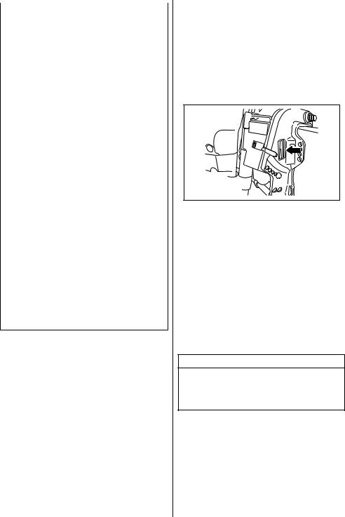
•Удостоверьтесь, что в лодке имеется комплект необходимого спасательного оборудования, такого как: индивидуальное спасательное средство для каждого пассажира, огнетушитель, фальшфейер, сигнальные устройства, якорь, весла, водоотливная помпа, веревка, аптечка первой помощи, набор инструментов, аварийный пусковой канат, фонарик, а также достаточный запас топлива, масла и т. д.
•Проинструктируйте пассажиров о действиях в случае аварии. Удостоверьтесь в том, что пассажиры понимают в общих чертах, как управлять лодкой, как пользоваться спасательным оборудованием и что делать в случае возникновенияпроблем.
•Не держитесь за крышку или другие части мотора при посадке в лодку и высадке из нее.
•Проверьте прогноз погоды перед плаванием.
•Будьте предельно осторожны при замене запчастей на моторе и выборе дополнительного оборудования. Помните, что применение несовместимых или некачественных запасных частей или аксессуаров, может вызвать поломку мотора и создать угрозу безопасности. SUZUKI настоятельно рекомендует использовать только фирменные запчасти или дополнительное оборудование. Использование любых других запасных частей и аксессуаров приведет к аннулированиюгарантии.
РАСПОЛОЖЕНИЕ
ИДЕНТИФИКАЦИОННОГО НОМЕРА МОТОРА
Идентификационный номер мотора выгравирован на пластине, закрепленной на кронштейне, как показано на рисунке внизу. Важно знать этот номер при заказе запчастей или в случае кражи мотора.
ТОПЛИВО И МАСЛА
БЕНЗИН
SUZUKI настоятельно рекомендует использовать неэтилированный и не содержащий спирт бензин с минимальным октановым числом 91 (по исследовательскому методу). В то же время, допускается использование смесей неэтилированного бензина и спирта с эквивалентным октановым числом при условии соблюдения указанных ниже требований.
ПРЕДОСТЕРЕЖЕНИЕ
Использование этилированного бензина может привести к повреждению мотора. Используйте только неэтилированный бензин.
SUZUKI настоятельно рекомендует установить на топливопроводе между топливным баком и мотором специальный фильтр, отделяющий воду от бензина. Система фильтрации такого типа предотвращает проникновение воды, которая может содержаться в топливном баке, в электронную систему впрыска топлива мотора. Проникновение воды может вызвать сбои в работе двигателя и повреждения компонентов электронной системы впрыска.
4

За дополнительной информацией по приобретению и установке подобных систем фильтрации обратитесь к авторизованному Дилеру SUZUKI.
Бензин, содержащийметилтетрабутиловый эфир (МТБЭ)
На моторе допускается использование неэтилированного бензина с содержанием МТБЭ (метилтетрабутилового эфира) при условии, что содержание МТБЭ не превышает 15%. Это кислородсодержащее топливо не содержит спирта.
Бензинэтаноловые смеси
Смеси неэтилированного бензина и метанола (зернового спирта) также известные как газохол, используются в некоторых районах. Бензин, содержащий не более 10 процентов этанола, может использоваться в моторе без опасений нарушить условия гарантии.
Бензинметаноловые смеси.
Также в некоторых местностях в продаже имеются смеси неэтилированного бензина и метанола (древесного спирта). Ни в коем случае НЕ ИСПОЛЬЗУЙТЕ смеси, содержащие более 5 процентов метанола. Повреждения топливной системы, возникшие при использовании такого топлива, не являются гарантийными случаями. Топливо, содержащее менее 5 процентов метанола, может использоваться только в том случае, если оно содержит сорастворители и антикоррозийные добавки.
Маркировка насосов для бензиноспиртовых смесей.
Внекоторых местностях требуется обязательная маркировка насосов, нагнетающих бензиноспиртовые смеси, с указанием типа и процентного содержания алкоголя, а также наличия важных добавок. Такие наклейки могут предоставлять всю необходимую информацию для определения соответствия определенной марки топлива приведенным выше требованиям.
Вдругих местностях насосы могут не иметь маркировки с четким указанием содержания и типа алкоголя и добавок. Если Вы не уверены, отвечает ли определенное топливо этим требованиям, обратитесь за помощью к оператору на топливной станции или поставщику топлива.
ЗАМЕЧАНИЕ Если Вы не удовлетворены работой или
экономичностью Вашего мотора при применении бензино-спиртовых смесей, используйте неэтилированный бензин, не содержащий спирт. Убедитесь, что любая смесь, которую Вы используете, имеет октановое число не менее 91 (по исследовательскому методу).
Если при работе двигатель издает ненормальные звуки («стучит»), попробуйте сменить марку бензина, поскольку характеристики бензина разных марок отличаются.
Применение неэтилированного бензина продлевает срок службы свечей.
ПРЕДОСТЕРЕЖЕНИЕ
Будьте осторожны, чтобы не пролить спиртосодержащее топливо. Спиртосодержащее топливо может повредить лакокрасочное покрытие мотора. Данное повреждение не является гарантийным случаем.
ОСТОРОЖНО
Бензинтоксиченилегковоспламеняется. При заправке бензином обязательно соблюдайте следующие меры предосторожности:
•Разрешайте заправлять топливный бак тольковзрослым.
•Перед заправкой топливного бака всегда останавливайте мотор и вынимайте топливныйбакизлодки.
•Не заливайте бензин в бак до краев, в противномслучаетопливоможетвытекать из бака, так как имеет свойство увеличиваться в объеме при нагревании подвоздействиемсолнечных лучей.
•Не проливайте топливо. Если это случилось, немедленно вытритеего.
•Не курите при заправке и держитесь подальше от огня, искр и других источниковоткрытогопламени.
•Выполняйте заправку в хорошо проветриваемыхместах.
•Избегайтедлительныхконтактовбензинас кожейиневдыхайтебензиновыепары.
5
ПРЕДОСТЕРЕЖЕНИЕ
Используйте только свежий бензин. В бензине, который хранился в топливном баке долгое время, может образовываться пленка или выпадать осадок, что может вызвать повреждение мотора.
Моторноемасло
Применение высококачественного 4-х тактного моторного масла продлит срок работы Вашего мотора. Используйте только масла с маркировкой SE, SF, SG, SH и SJ,
сертифицированные по системе API. Вязкость масла должна быть SAE 10W-40. Если по каким либо причинам Вы не можете использовать масло с такой вязкостью, выберите альтернативное масло в соответствии с приведенной ниже таблицей.
ПРЕДОСТЕРЕЖЕНИЕ
Использование качественного моторного масла существенно сказывается на работе мотораипродлеваетсрокегослужбы.
Трансмиссионноемасло
Используйте SUZUKI OUTBOARD MOTOR GEAR OIL или эквивалентное ему высококачественное гипоидное трансмиссионное масло SAE 90.
6
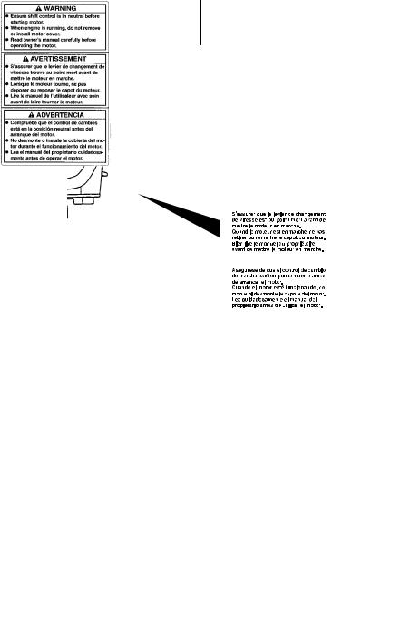
РАСПОЛОЖЕНИЕ ПРЕДУПРЕДИТЕЛЬНЫХ НАКЛЕЕК
Прочтите и соблюдайте инструкции на всех Сохраняйте наклейки на моторе и топливном наклейках, расположенных на моторе и баке. Ни в коем случае не удаляйте их. топливном баке. Убедитесь в том, что Вы уяснили инструкции на всех наклейках.
7
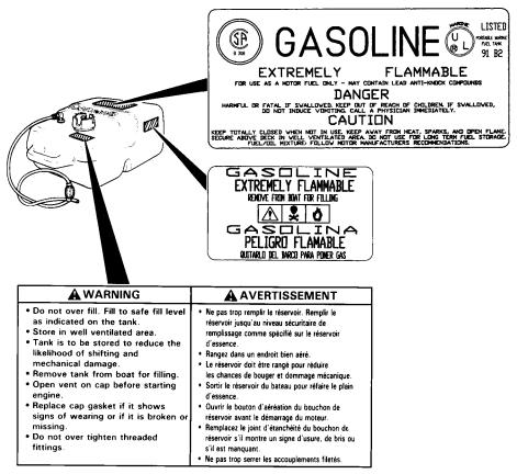
8
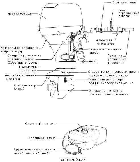
КОНСТРУКЦИЯ МОТОРА
Моделисручнымуправлением
9

Моделисдистанционнымуправлением
10
![]()
ОСТОРОЖНО
Аккумуляторные батареи вырабатывают взрывоопасные газы. Не курите вблизи и держитевдалиотисточниковоткрытогоогня иискр.
ПРЕДОСТЕРЕЖЕНИЕ
Закрепите аккумуляторную батарею на лодке в сухом месте, мало подверженном вибрации. Чтобы подключить аккумулятор, сначала подсоедините красный провод от мотора к положительной фазе аккумулятора, а затем подсоедините черный провод к отрицательной.
|
УСТАНОВКА МОТОРА |
УСТАНОВКА |
|||||||
|
АККУМУЛЯТОРА |
||||||||
|
ОСТОРОЖНО |
SUZUKI рекомендует использовать |
только |
||||||
|
Никогда не нагружайте лодку больше |
||||||||
|
высококачественные аккумуляторные |
батареи, |
|||||||
|
предельно |
разрешенной |
массы. |
Не |
отвечающие всем |
минимально необходимым |
|||
|
устанавливайте мотор, мощность которого |
требованиям, указанным ниже. |
|||||||
|
превышает |
максимально |
допустимую |
||||||
|
мощность для Вашей лодки, указанную на |
||||||||
|
Тип |
Marine (Морской) |
|||||||
|
табличке с техническими характеристиками |
||||||||
|
лодки. Если Вы не можете определить |
Ток холодной |
|||||||
|
допустимую мощность лодки, обратитесь к |
прокрутки |
389 ампер и более |
||||||
|
авторизованномуДилеруSUZUKI. |
(CCA) |
|||||||
|
Резервная |
115 мин. и более |
|||||||
|
SUZUKI настоятельно рекомендует, чтобы |
емкость (RC) |
|||||||
|
установку мотора и сопутствующих приборов |
Емкость в |
12 вольт, 70 ампер-часов и |
||||||
|
осуществляли |
только авторизованные |
Дилеры |
ампер-часах |
более |
||||
|
SUZUKI. У дилера имеются все необходимые |
||||||||
|
инструменты, оборудование и знания. |
ОСТОРОЖНО
Неправильная установка мотора и сопутствующих приборов может привести к травмамилиповреждениям.
Не размещайте аккумулятор рядом с топливнымбаком.
11

Чтобы демонтировать аккумулятор, сначала отсоедините черный провод от отрицательной фазы, затем красный от положительной.
ПРЕДОСТЕРЕЖЕНИЕ
•Внимательно проверяйте правильность присоединения проводов. Неправильное подсоединение проводов может привести к повреждениюэлектрическойсистемы.
•Не отсоединяйте провода от аккумулятора во время работы мотора. Это может привести к повреждению электрических частей.
ИСПОЛЬЗОВАНИЕ
ДОПОЛНИТЕЛЬНЫХ
ЭЛЕКТРОННЫХ
УСТРОЙСТВ
Мощность (12 В постоянного тока), доступная для подключения дополнительных устройств, зависит от условий работы мотора. Для получения более подробной информации проконсультируйтесь с авторизованным Дилером SUZUKI.
12
ВЫБОР И УСТАНОВКА ГРЕБНОГО ВИНТА
Выборвинта
При выборе винта учитывайте характеристики лодки и условия ее эксплуатации. Помните, что скорость двигателя при работе с полностью открытым дросселем зависит от используемого гребного винта.
ПРЕДОСТЕРЕЖЕНИЕ
Установка винта со слишком большим или, наоборот, со слишком малым шагом, может вызвать нарушения максимальной скорости двигателя, что может привести к серьезным поврежденияммотора.
Рабочийдиапазонпри
полностью открытом 5900 – 6500 дросселе: об/мин
Установкавинта
ОСТОРОЖНО
•При установке или снятии винта убедитесь, что ручка переключения передач находится в нейтральном положении и провода свечи зажигания отсоединены, чтобы предотвратить случайныйзапускмотора.
•Чтобы не порезаться лопастями винта, оденьте перчатки. Поместите деревянный брусок между антикавитационной пластиной и винтом для удержания винта наместе.
Для установки винта выполните следующую процедуру:
1.Смажьте шлицы гребного вала 1 специальной водозащитной смазкой для предотвращения коррозии.
2.Наденьте фиксатор 2 на гребной вал.
3.Выровняйте винт 3 со шлицами гребного вала и наденьте винт на вал.
4.Наденьте втулку уплотнения 4 и шайбу 5 на гребной вал.
5.Наденьте гайку винта 6 и затяните ее с усилием 50-60 Нм.
6.Установите шплинт 7 и согните его, чтобы он не выскочил.
Чтобы снять винт, выполните вышеописанные действия в обратном порядке.
13
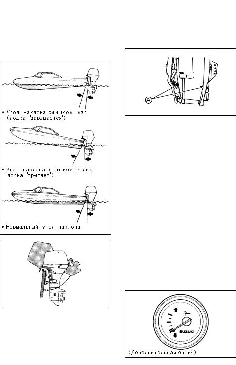
РЕГУЛИРОВКИ
Регулировкаугладифферента
Для обеспечения стабильного управления и хорошего КПД поддерживайте надлежащий угол дифферента, как показано на рисунке. Необходимый угол зависит от характеристик лодки, мотора, винта и условий эксплуатации.
Модельсуправлениемнарумпеле
Чтобы отрегулировать угол наклона:
1.Зафиксируйте мотор в полностью поднятом положении. (См. раздел «Фиксатор откидки».)
2.Установите штыри наклона A в нужных гнездах.
3. Опустите мотор.
Чтобы опустить нос лодки, переместите штыри по направлению к лодке.
Чтобы приподнять нос лодки, переместите штыри по направлению от лодки.
Модельсдистанционнымуправлением
Осуществите пробную поездку на лодке, чтобы определить, нуждается ли угол дифферента в регулировке. Настройте оптимальный угол наклона мотора при помощи системы гидравлического подъемника (P.T.T.). При необходимости Вы можете изменить предельный уровень хода наклона, который можно установить с помощью системы подъемника, передвинув штырь наклона в другое положение.
Во время управления лодкой с отрегулированным углом наклона мотора обращайте внимание на то, в каком положении находится стрелка датчика подъема ноги мотора (предлагается в качестве опционной части). При регулировке угла поднятия ноги мотора в будущем Вы можете настраивать угол, пользуясь показаниями этого датчика.
14
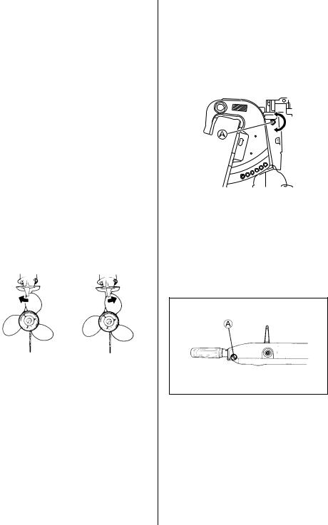
|
Регулировкастабилизатора |
Настройкаусилиярулевогоуправления |
||||||||||||
|
Эта настройка используется для того, чтобы |
Управление мотором |
должно |
осуществляться |
||||||||||
|
компенсировать |
возможное |
незначительное |
ровно и без усилий. |
||||||||||
|
отклонение лодки от курса под воздействием |
Настройте жесткость рулевого управления таким |
||||||||||||
|
силы вращения винта, |
положения мотора и т.д. |
образом, чтобы прикладывать минимальные |
|||||||||||
|
усилия при управлении. |
|||||||||||||
|
Чтобы отрегулировать стабилизатор: |
Чтобы |
увеличить |
силу |
сопротивления, |
|||||||||
|
1. Ослабьте |
винт |
A, |
удерживающий |
поверните регулятор A по часовой стрелке, |
|||||||||
|
стабилизатор на месте. |
чтобы уменьшить – против. |
||||||||||||
|
2. Если лодка отклоняется в сторону правого |
Настройкаусилияповоротарукоятки |
||||||
|
борта, |
поверните |
тыльную |
часть |
||||
|
стабилизатора по направлению к правому |
управлениядросселем |
||||||
|
борту, если лодка отклоняется в сторону |
(Модель с управлением на румпеле) |
||||||
|
левого борта, поверните стабилизатор по |
Жесткость управления дросселем может быть |
||||||
|
направлению к левому борту. |
отрегулирована в соответствии с Ваши |
||||||
|
предпочтениями. Чтобы увеличить жесткость, |
|||||||
|
поверните регулятор A по часовой стрелке, |
|||||||
|
чтобы уменьшить – против. |
|||||||
3.Закрутите болт, удерживающий стабилизатор на месте.
После выполнения регулировки проверьте, отклоняется ли лодка в какую-либо сторону. Если необходимо, выполните регулировку стабилизатора еще раз.
15
 Loading…
You can only view or download manuals with
Sign Up and get 5 for free
Upload your files to the site. You get 1 for each file you add
Get 1 for every time someone downloads your manual
Buy as many as you need

Руководство по эксплуатации и техническому обслуживанию подвесного лодочного мотора Suzuki модели DT2.2.
- Год издания: —
- Страниц: 26
- Формат: PDF
- Размер: 1,0 Mb

Сборник руководств по эксплуатации и техническому обслуживанию + технический паспорт подвесного лодочного мотора Suzuki модели DF2.5.
- Год издания: —
- Страниц: 34+46
- Формат: PDF
- Размер: 2,3 Mb

Сборник руководств по эксплуатации и техническому обслуживанию подвесных лодочных моторов Suzuki моделей DF4, DF5 и DF6.
- Год издания: —
- Страниц: 39+50
- Формат: PDF
- Размер: 4,2 Mb

Руководство по эксплуатации и техническому обслуживанию подвесных лодочных моторов Suzuki моделей DF8A и DF9.9A.
- Год издания: —
- Страниц: 66
- Формат: PDF
- Размер: 2,0 Mb

Руководство по эксплуатации и техническому обслуживанию подвесных лодочных моторов Suzuki моделей FD9.9 и DF15.
- Год издания: —
- Страниц: 41
- Формат: PDF
- Размер: 1,7 Mb
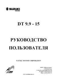
Сборник руководств по эксплуатации и техническому обслуживанию подвесных лодочных моторов Suzuki моделей DT9.9-DT15.
- Год издания: —
- Страниц: 38+51
- Формат: PDF
- Размер: 3,0 Mb
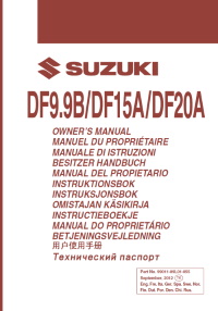
Руководство по эксплуатации и техническому обслуживанию подвесных лодочных моторов Suzuki моделей DF9.9B, DF15A и DF20A.
- Год издания: —
- Страниц: 70
- Формат: PDF
- Размер: 2,4 Mb

Руководство по эксплуатации и техническому обслуживанию подвесных лодочных моторов Suzuki моделей DF20 и DF25.
- Год издания: —
- Страниц: 50
- Формат: PDF
- Размер: 1,5 Mb

Сборник руководств по эксплуатации и техническому обслуживанию подвесного лодочного мотора Suzuki модели DT30.
- Год издания: —
- Страниц: 40+56
- Формат: PDF
- Размер: 4,0 Mb

Руководство по эксплуатации и техническому обслуживанию подвесных лодочных моторов Suzuki моделей DF40 и DF50.
- Год издания: —
- Страниц: 36
- Формат: PDF
- Размер: 1,2 Mb

Сборник руководств по эксплуатации и техническому обслуживанию подвесных лодочных моторов Suzuki моделей DF40A, DF50A и DF60A.
- Год издания: —
- Страниц: 31+72
- Формат: PDF
- Размер: 22,5 Mb
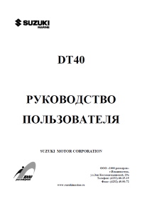
Руководство по эксплуатации и техническому обслуживанию подвесного лодочного мотора Suzuki модели DT40.
- Год издания: —
- Страниц: 37
- Формат: PDF
- Размер: 2,7 Mb

Руководство по эксплуатации и техническому обслуживанию подвесных лодочных моторов Suzuki моделей DT40W, DT40WE и DT40WR.
- Год издания: —
- Страниц: 22
- Формат: PDF
- Размер: 2,6 Mb

Руководство по эксплуатации и техническому обслуживанию подвесного лодочного мотора Suzuki модели DT40WK.
- Год издания: —
- Страниц: 24
- Формат: PDF
- Размер: 1,3 Mb

Руководство по эксплуатации и техническому обслуживанию подвесного лодочного мотора Suzuki модели DF50W.
- Год издания: —
- Страниц: 49
- Формат: PDF
- Размер: 1,2 Mb

Руководство по эксплуатации и техническому обслуживанию подвесных лодочных моторов Suzuki моделей DF60 и DF70.
- Год издания: —
- Страниц: 36
- Формат: PDF
- Размер: 1,2 Mb
Сборник руководств по эксплуатации и техническому обслуживанию подвесных лодочных моторов Suzuki моделей DF70A, DF80A и DF90A.
- Год издания: —
- Страниц: 45+69
- Формат: PDF
- Размер: 8,1 Mb

Руководство по эксплуатации и техническому обслуживанию подвесного лодочного мотора Suzuki модели DF70W.
- Год издания: —
- Страниц: 49
- Формат: PDF
- Размер: 1,2 Mb
Руководство по эксплуатации и техническому обслуживанию подвесных лодочных моторов Suzuki моделей DF90, DF115 и DF140.
- Год издания: —
- Страниц: 41
- Формат: PDF
- Размер: 1,4 Mb
Руководство на английском языке по техническому обслуживанию и ремонту подвесных лодочных моторов Suzuki моделей DF90, DF100, DF115 и DF140.
- Год издания: —
- Страниц: 616
- Формат: PDF
- Размер: 42,9 Mb

Руководство по эксплуатации и техническому обслуживанию подвесных лодочных моторов Suzuki моделей DF115W и DF140W.
- Год издания: —
- Страниц: 49
- Формат: PDF
- Размер: 1,3 Mb
Сборник руководств по эксплуатации и техническому обслуживанию подвесных лодочных моторов Suzuki моделей DF150 и DF175.
- Год издания: —
- Страниц: 43+59
- Формат: PDF
- Размер: 2,6 Mb
Руководство по эксплуатации и техническому обслуживанию подвесных лодочных моторов Suzuki моделей DF200, DF225 и DF250.
- Год издания: —
- Страниц: 61
- Формат: PDF
- Размер: 1,6 Mb

Руководство по эксплуатации и техническому обслуживанию подвесных лодочных моторов Suzuki моделей DF200W, DF225W и DF250.
- Год издания: —
- Страниц: 52
- Формат: PDF
- Размер: 1,4 Mb
Руководство по эксплуатации и техническому обслуживанию подвесных лодочных моторов Suzuki моделей DF250AP и DF300AP.
- Год издания: —
- Страниц: 78
- Формат: PDF
- Размер: 2,0 Mb
Руководство по эксплуатации и техническому обслуживанию подвесного лодочного мотора Suzuki модели DF300.
- Год издания: —
- Страниц: 51
- Формат: PDF
- Размер: 1,3 Mb
