| Корпус | Самозатухающий пластик ABS |
| Размер | Спереди 32×74мм; глубина 50м м |
| Монтаж | На панель в вырез размером 71×29мм |
| Защита | IP20 |
| Защита спереди | IP65 |
| Соединения | Клеммная колодка с зажимами под винт, сечение провода ≤ 2,5м м |
| Электропитание | Согласно модели: 110В пер.тока ±10%, 50/60Г ц — 230В пер.тока ±10%, 50/60Г ц |
| Энергопотребление | 3,5ВА макс. |
| Дисплей | 2 цифры, красные светодиоды высотой 14,2м м |
| Входы | 1 NTC |
| Цифрово й вход | контакты без напряжения |
| Релейные выходы | компрессор SPST 20(8)А 250В пер.тока и ли 8(3)A 250В пер.тока |
| Сохранение данных | в энергонезависимой памяти (EEPROM) |
| Рабочая температура | 0÷60°C |
| Температура хранения | -25÷60°C |
| Относительная влажность | 20÷85% (без конденсации) |
| Диапазон измерения и регулирования | NTC -датчик: -40÷110°C |
| Разрешение | 0,1°C и ли 1°C и ли 1°F (выбирается) |
| Точность (окруж. темп. 25°C) | ±0,1 °C ±1 з нак |
Регулирование выполняется согласно температуре, измеренной датчиком термостата с положительной разницей от уставки: если температура растет и достигает уставки плюс дифференциал, то компрессор запускается и затем выключается, когда температура снова достигнет значения уставки. При повреждении датчика термостата, пуск и остановка компрессора осуществляется по времени согласно параметров Cy и Cn.
Значение Hy автоматически вычитается из уставки. Если температура растет и достигает уставки минус дифференциал, то сработает выход и затем выключится, когда температура снова достигнет значения уставки.
Контроллеры должны монтироваться на вертикальной панели в вырез 29×71мм и закрепляться, используя поставляемые специальные держатели.
Диапазон температур, разрешенный для правильной эксплуатации -0÷60°C. Избегайте мест, подверженных сильной вибрации, с присутствием агрессивных газов, чрезмерной запыленностью или влажностью. Те же рекомендации применяйте и к датчикам. Позвольте воздуху циркулировать через отверстия для охлаждения.
| Параметр | Описание |
| Регулирование | |
| Hy | Дифференциал: (0,1°C ÷ 25°C / 1°F ÷ 45°F) Дифференциал срабатывания уставки. ВКЛ (Cut IN) компрессора — это Уставка + дифференциал (Hy). ВЫКЛ (Cut OUT) компрессора – когда температура достигнет уставки. |
| LS | Минимальная Уставка: (-55°C÷SET/-67°F÷SET): Задает мин. значение уставки. |
| US | Максимальная Уставка: (SET÷99°C/ SET÷99°F). Задает макс. значение уставки. |
| ot | Калибровка первого датчика: (-9.9÷9.9°C / -17÷17°F) позволяет скорректировать возможное отклонение первого датчика. |
| od | Задержка активации выходов при запуске: (0÷99м ин ) Эта функция доступна при первичном запуске контроллера и задерживает активацию любого выхода на время, заданное в этом параметре. |
| AC | Задержка против коротких циклов: (0÷50 мин ) минимальный интервал между остановкой компрессора и последующим перезапуском. |
| Cy | Время ВКЛ компрессора с неисправным датчиком: (0÷99 мин ) время, в течение которого компрессор работает при неисправном датчике термостата. При Cy=0 компрессор всегда ВЫКЛ. |
| Cn | Время В Ы КЛ компрессора с неисправным датчиком: (0÷99 мин ) время, в течение которого компрессор ВЫКЛ при неисправном датчике термостата. При Cn=0 компрессор всегда включен. |
| CH | Тип действия: cL= о хлаждение; Ht = нагрев |
| Визуализация | |
| CF | Единицы измерения: (°C÷°F) °C=градусы Цельсия; °F=градусы Фаренгейта. |
| rE | Разрешение (д ля °C):(dE ÷ in) dE= с десятичной точкой от -9.9 д о 9.9°C; in= целое |
| dy | Задержка и ндикации : (0÷ ÷15 мин ) когда температура растет, дисплей обновляется на 1°C/1°F по истечении этого времени. |
| Аварии | |
| AU | Авария по Макс. температуре: (AL÷99°C/99°F) когда достигается эта температура, после задержки времени Ad, активируется авария. |
| AL | Авария по Мин. температуре: (-55÷AU°C /-67÷AU°F) когда достигается эта температура, после задержки времени Ad, активируется авария. |
| Ad | Задержка аварии по температуре: (0÷99 мин ) Интервал времени между обнаружением условий аварии и соответствующим сигналом аварии. |
| dA | Исключение аварии по температуре при п одаче питания: (0÷99 мин ) Интервал между обнаружением условий аварии после подачи питания на контроллер и сигналом аварии. |
| Цифровой вход | |
| iP | Полярность цифрового входа: (oP ÷ cL) oP = цифровой вход активируется по размыканию контакта; cL = цифровой вход активируется по з а мыканию контакта. |
| iF | Конфигурация цифрового входа: (EA/bA/do/dF/Au/Hc) EA = внешняя авария: отображается сообщение EA; bA = серьезная авария, отображается сообщение CA; do = функция дверного контакта; dF = запуск оттайки; Au = не используется; Hc = изменение типа действия. |
| di | Задержка аварии цифрового входа: (0÷99м ин ) при iF = EA или bA задержка между обнаружением условий внешней аварии и последующим сигналом. При iF=do п редставляет задержку активации аварии открытия двери. |
| dC | Состояние компрессора и вентилятора при открытой двери: (no/Fn/cP/Fc): no = нормальное; Fn = Вентилятор ВЫКЛ; cP = Компрессор ВЫКЛ; Fc = Компрессор и вентилятор ВЫКЛ. |
| rd | Регулирование при открытой двери: (n÷y) n = нет регулирования, если дверь открыта; Y= когда задержка Ц.Вх. истекла, регулирование возобновляется даже при наличии аварии открытия двери. |
| Другие параметры | |
| Pt | Таблица кодов параметров |
| rL | Версия программного обеспечения |
DIGITAL CONTROLLER
XR01-02CX
1.
CONTENTS
1.
Contents ____________________________________________________________________________ 1
2.
General warnings _____________________________________________________________________ 1
3.
General description ___________________________________________________________________ 1
4.
Regulation __________________________________________________________________________ 1
5.
Defrost (ONLY XR02CX) _______________________________________________________________ 1
6.
Front panel commands ________________________________________________________________ 1
7.
Parameters __________________________________________________________________________ 2
8.
Digital inputs _________________________________________________________________________ 2
9.
Installation and mounting _______________________________________________________________ 2
10.
Electrical connections _________________________________________________________________ 2
11.
How to use the hot key_________________________________________________________________ 2
12.
Alarm signalling ______________________________________________________________________ 2
13.
Technical data _______________________________________________________________________ 2
14.
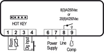
Connections _________________________________________________________________________ 3
15.
Default setting values __________________________________________________________________ 3
2.
GENERAL WARNINGS
2.1
PLEASE READ BEFORE USING THIS MANUAL
This manual is part of the product and should be kept near the instrument for easy and quick
reference.
The instrument shall not be used for purposes different from those described hereunder. It cannot be
used as a safety device.
Check the application limits before proceeding.
Dixell Srl reserves the right to change the composition of its products, even without notice, ensuring
the same and unchanged functionality.
2.2
SAFETY PRECAUTIONS
Check the supply voltage is correct before connecting the instrument.
Do not expose to water or moisture: use the controller only within the operating limits avoiding sudden
temperature changes with high atmospheric humidity to prevent formation of condensation
Warning: disconnect all electrical connections before any kind of maintenance.
Fit the probe where it is not accessible by the End User. The instrument must not be opened.
In case of failure or faulty operation send the instrument back to the distributor or to «Dixell S.r.l.» (see
address) with a detailed description of the fault.
Consider the maximum current which can be applied to each relay (see Technical Data).
Ensure that the wires for probes, loads and the power supply are separated and far enough from each
other, without crossing or intertwining.
In case of applications in industrial environments, the use of mains filters (our mod. FT1) in parallel with
inductive loads could be useful.
3.
GENERAL DESCRIPTION
Model XR01CX, format 32 x 74 x50 mm format is a single stage temperature controller suitable for
applications in the field of refrigeration or heating. It provides a relay output to drive the compressor. It is also
provided with 1 NTC probe input and one configurable digital input. The instrument is fully configurable
through special parameters that can be easily programmed through the keyboard or the by HOTKEY.
Model XR02CX, format 32 x 74 x 50 mm, is a digital thermostat with off cycle defrost designed for
refrigeration applications at normal temperature. It provides a relay output to drive the compressor. It is also
provided with 1 NTC probe input and one configurable digital input. The instrument is fully configurable
through special parameters that can be easily programmed through the keyboard or the by HOTKEY.
4.
REGULATION
4.1
THE REGULATION OUTPUT
The regulation is performed according to the temperature measured by probe. The XR01CX is provided with
the CH programmable parameter wich enables the user to set the regulation both for heating or cooling
applications:
CH=cL —> cooling applications;
CH=Ht —> heating applications;
4.2
COOLING APPLICATIONS
The regulation is performed according to
the
temperature
measured
by
the
thermostat probe with a positive differential
from the set point: if the temperature
increases and reaches set point plus
differential the compressor is started and
then turned off when the temperature
reaches the set point value again.
In case of fault in the thermostat probe the start and stop of the compressor are timed through parameters
«Cy» and «Cn».
4.3
HEATING APPLICATIONS ( ONLY FOR XR01CX)
The Hy value is automatically subtracted to
the SET POINT. If the temperature decreases
and reaches set point minus differential the
output is started and then turned off when the
temperature reaches set point value again.
1592020110 XR01-02CX GB r1.2 24.07.2015
5.
DEFROST (ONLY XR02CX)
Defrost is performed through a simple stop of the compressor. Parameter «id» controls the interval
between defrost cycles, while its length is controlled by parameter «Md».
6.
FRONT PANEL COMMANDS
KEYS COMBINATION
+
To lock or unlock the keyboard
+
To enter in programming mode
+
To return to room temperature display
LED
MODO
On
Compressore enabled
Flashing
Anti short cycle delay enabled (AC parameter)
On
Defrost in progress
Flashing
Dripping in progress
On
Measurement unit
Flashing
Programming mode
On
Measurement unit
Flashing
Programming mode
6.1
HOW TO SEE THE SET POINT
1.
Push and immediately release the SET key, the set point will be showed;
2.
Push and immediately release the SET key or wait about 5s to return to normal visualisation.
6.2
HOW TO CHANGE THE SETPOINT
1.
Push the SET key for more than 2 seconds to change the Set point value;
2.
The value of the set point will be displayed and the «°C» or «°F» LED starts blinking;
3.
To change the Set value push the o or n arrows within 10s.
4.
To memorise the new set point value push the SET key again or wait 10s.
6.3
HOW TO START A MANUAL DEFROST (ONLY XR02CX)
Push the DEF
key for more than 2 seconds and a manual defrost will start
6.4
HOW TO CHANGE A PARAMETER VALUE
To change the parameter’s value operate as follows:
1. Enter the Programming mode by pressing the SET+
blinking).
2. Select the required parameter. Press the «SET» key to display its value
3. Use
or
to change its value.
4. Press «SET» to store the new value and move to the following parameter.
To exit: Press SET+
or wait 15s without pressing a key.
NOTE: the set value is stored even when the procedure is exited by waiting the time-out to expire.
6.5
HIDDEN MENU
The hidden menu includes all the parameters of the instrument.
HOW TO ENTER THE HIDDEN MENU
1. Enter the Programming mode by pressing the SET+
blinking).
2. Released the keys, then push again the SET+
displayed immediately followed from the Hy parameter.
NOW YOU ARE IN THE HIDDEN MENU.
3. Select the required parameter.
4. Press the «SET» key to display its value
5. Use
or
to change its value.
6. Press «SET» to store the new value and move to the following parameter.
To exit: Press SET+
or wait 15s without pressing a key.
NOTE1: if none parameter is present in L1, after 3s the «nP» message is displayed. Keep the keys
pushed till the L2 message is displayed.
NOTE2: the set value is stored even when the procedure is exited by waiting the time-out to expire.
HOW TO MOVE A PARAMETER FROM THE HIDDEN MENU TO THE FIRST
LEVEL AND VICEVERSA.
Each parameter present in the HIDDEN MENU can be removed or put into «THE FIRST LEVEL» (user
level) by pressing SET+
. In HIDDEN MENU when a parameter is present in First Level the decimal
point is on.
6.6
TO LOCK THE KEYBOARD
1.
Keep pressed for more than 3s the
2.
The «OF» message will be displayed and the keyboard will be locked. If a key is pressed more
than 3s the «OF» message will be displayed.
6.7
TO UNLOCK THE KEYBOARD
Keep pressed together for more than 3s the
XR01-02CX
To display target set point, in
programming mode it selects a
parameter
operation
To start a manual defrost (Only
XR02CX)
In programming mode it browses
the parameter codes or increases
the displayed value
In programming mode it browses
the
parameter
AUX
decreases the displayed value
SIGNIFICATO
keys for 3s («°C» or «°F» LED starts
keys for 3s («°C» or «°F» LED starts
keys for more than 7s. The L2 label will be
and
keys.
and
keys till the «on» message will be displayed.
or
confirm
an
codes
or
1/3
Файл |
Дата | Загрузки | Комментарии | |
|---|---|---|---|---|

|
XLR 130-170 RU : Русская инструкция на Dixell XL … [ещё] (788.0 Кб) |
18.07.2012 | 91 | 0 |
|
|
XLR 470RU : Русская инструкция на Dixell XL … [ещё] (1.59 Мб) |
19.07.2012 | 40 | 0 |
|
|
XM244L RU : Русская инструкция на Dixell XM … [ещё] (320.3 Кб) |
25.10.2011 | 58 | 0 |
|
|
XM440_460K RU : Русская инструкция на Dixell XM … [ещё] (1.99 Мб) |
25.10.2011 | 131 | 0 |
|
|
XM660K_XM669K RU : Русская инструкция на Dixell XM … [ещё] (541.3 Кб) |
25.10.2011 | 73 | 0 |
|
|
XM668D RU : Русская инструкция на Dixell XM … [ещё] (1.46 Мб) |
25.10.2011 | 61 | 0 |
|
|
XM668_2_6_RU : Русская инструкция на Dixell XM … [ещё] (1.89 Мб) |
16.09.2015 | 18 | 0 |
|
|
XM669K_3_4_RUS : Русская инструкция на Dixell XM … [ещё] (1.60 Мб) |
28.08.2014 | 27 | 0 |
|
|
XM670K_XM679K : Русская инструкция на Dixell XM … [ещё] (585.9 Кб) |
25.10.2011 | 79 | 0 |
|
|
XP110C — XP111C — XP110D — XP111D — XP111R_rus : (283.8 Кб) |
13.09.2011 | 64 | 0 |
|
|
XR, XT, Prime Series : XR100/500 Series — Refrigeration Controller |
28.02.2010 | 322 | 2 |
|
|
XR01_02CX_RU : Русская инструкция на Dixell XR … [ещё] (1.14 Мб) |
28.10.2011 | 113 | 0 |
|
|
XR02CX : eng (273.7 Кб) |
05.10.2009 | 116 | 0 |
|
|
XR03_04CX_RU : Русская инструкция на Dixell XR … [ещё] (1.79 Мб) |
28.10.2011 | 72 | 0 |
|
|
XR06CX RU : Русская инструкция на Dixell XR … [ещё] (340.0 Кб) |
28.10.2011 | 135 | 0 |
|
|
XR10CX_RU : Русская инструкция на Dixell XR … [ещё] (289.0 Кб) |
13.09.2013 | 39 | 0 |
|
|
XR120C : мануал (12.1 Кб) |
11.06.2011 | 52 | 0 |
|
|
XR160-170D RU : Русская инструкция на Dixell XR … [ещё] (696.4 Кб) |
25.04.2014 | 40 | 0 |
|
|
XR20CX RU : Русская инструкция на Dixell XR … [ещё] (1.07 Мб) |
28.10.2011 | 159 | 0 |
|
|
XR60CX RU : Русская инструкция на Dixell XR … [ещё] (310.0 Кб) |
28.10.2011 | 167 | 0 |
Сортировать по
Сортировка
DIXELL XR01CX

Модель XR01CX Е-класса (эконом), в формате 32 х 74 х 50 мм — это одноступенчатый температурный контроллер, подходящий для применения в области охлаждения или нагрева. У него имеется релейный выход для управления компрессором. Контроллер XR01CX также снабжен 1-м входом для датчика NTC и одним конфигурируемым цифровым входом. При возникновении аварийной ситуации на дисплее контроллера появляется код аварии. Прибор легко и быстро программируется с помощью ключа HOTKEY. Модель XR01CX с привлекательным дизайном я вляется аналогом XR10C.
Функции прибора XR01CX
- Регулирование
- Регулировка температуры
- Дифференциал
- Минимальная контрольная точка
- Максимальная контрольная точка
- Калибровка датчика температуры помещения
- Задержка активации выходов после подачи напряжения питания
- Противоцикличная задержка
- Время работы компрессора при неисправном датчике
- Время выключения компрессора при неисправном датчике
- Отображение
- Единица измерения температуры
- Разрешающая способность (целое/десятичное число)
- Задержка индикации
- Предупреждения
- Сигнал тревоги по максимальной температуре
- Сигнал тревоги по минимальной температуре
- Задержка температурного сигнала тревоги
- Задержка температурного сигнала тревоги после подачи питания
- Цифровой вход
- Выбор полярности цифрового входа
- Конфигурация цифрового входа
- Задержка сигнала тревоги с цифрового входа
- Статус компрессора и вентилятора, при открытой двери
- Регулирование при открытой двери
- Другие
- Отображение датчика помещения
- Версия программного обеспечение
- Запись параметров на ключ программирования и обратно
Технические данные XR01CX
- Корпус: самозатухающий пластик ABS
- Размеры: XR01CХ передняя панель 32×74 мм; глубина 50мм
- Монтаж: XR01СХ устанавливается в отверстие 71х29мм
- Защита передней панели: IP65; Защита прибора: IP20
- Соединения: клеммная колодка с зажимами под винт, сечение провода <2.5мм2.
- Напряжение питания: XR01CХ на выбор ~230,110B. ±10%, 50/60Гц)
- Энергопотребление: 3.5 VA макс.
- Дисплей: 2 цифры, красные LED, 14,2 мм высота.
- Вход: 1 датчик NTC.
- Цифровой вход: контакты без напряжения.
- Релейные выходы:
- компрессор: SPST 8(3)А 250В АС или 20(8)А 250В АС.
- Блок памяти: данные сохраняются даже при отсутсвии питания (EEPROM).
- Класс применения: 1В; Степень загрязнения окр. среды: 2; Класс ПО: A.
- Макс. допустимое импульсное напряжение: 2500B; Категория перенапряжения: II
- Рабочая температура: 0…+60°C.
- Температура хранения: -25…+60°C.
- Относительная влажность: 20…85% (отсутствие какого-либо конденсата)
- Диапазон измерения и регулеровки: NTC-датчик: -40…+110°C
- Разрешающая способность: 0,1°C или 1°C или 1°F (на выбор).
- Точность (при температуре окружающей среды 25°C): ±0,1°C ±1 цифра

Operating Manual + DIGITAL CONTROL FOR HEATING LED XR01CX 1. CONTENTS 1. 2. 3. 4. 5. 6. 7. 8. 9. 10. 11. 12. 13. 14. Contents __________________________________________________________________________ 1 General warnings ___________________________________________________________________ 1 General description __________________________________________________________________ 1 Regulation _________________________________________________________________________ 1 Front panel commands _______________________________________________________________ 1 Parameters ________________________________________________________________________ 1 Digital inputs _______________________________________________________________________ 2 Installation and mounting _____________________________________________________________ 2 Electrical connections ________________________________________________________________ 2 How to use the hot key _______________________________________________________________ 2 Alarm signalling _____________________________________________________________________ 2 Technical data ______________________________________________________________________ 2 Connections _______________________________________________________________________ 2 Default setting values ________________________________________________________________ 2 2. GENERAL WARNINGS This manual is part of the product and should be kept near the instrument for easy and quick reference. The instrument shall not be used for purposes different from those described hereunder. It cannot be used as a safety device. Check the application limits before proceeding. SAFETY PRECAUTIONS Model XR01CX, format 32 x 74 format is a single stage temperature controller suitable for applications in the field of refrigeration or heating. It provides a relay output to drive the compressor. It is also provided with 1 NTC or PTC probe input and one digital input. The instrument is fully configurable through special parameters that can be easily programmed through the keyboard or the by HOTKEY. 1. 2. Push and immediately release the SET key, the set point will be showed; Push and immediately release the SET key or wait about 5s to return to normal visualisation. HOW TO CHANGE THE SETPOINT 1. 2. 3. 4. Push the SET key for more than 2 seconds to change the Set point value; The value of the set point will be displayed and the “°C” or “°F” LED starts blinking; To change the Set value push the o or n arrows within 10s. To memorise the new set point value push the SET key again or wait 10s. HOW TO CHANGE A PARAMETER VALUE HOW TO MOVE A PARAMETER FROM THE HIDDEN MENU TO THE FIRST LEVEL AND VICEVERSA. Each parameter present in the HIDDEN MENU can be removed or put into “THE FIRST LEVEL” (user level) by pressing SET+ . In HIDDEN MENU when a parameter is present in First Level the decimal point is on. 4. REGULATION The regulation is performed according to the temperature measured by probe. The XR01CX is provided with the CH programmable parameter wich enables the user to set the regulation both for heating or cooling applications: CH=cL --> cooling applications; CH=Ht --> heating applications; TO LOCK THE KEYBOARD 1. 2. COOLING APPLICATIONS The regulation is performed according to the temperature measured by the thermostat probe with a positive differential from the set point: if the temperature increases and reaches set point plus differential the compressor is started and then turned off when the temperature reaches the set point value again. Keep pressed for more than 3s the and keys. The “OF” message will be displayed and the keyboard will be locked. If a key is pressed more than 3s the “OF” message will be displayed. TO UNLOCK THE KEYBOARD Keep pressed together for more than 3s the and keys till the “on” message will be displayed. 6. PARAMETERS REGULATION In case of fault in the thermostat probe the start and stop of the compressor are timed through parameters “Cy” and “Cn”. HEATING APPLICATIONS The Hy value is automatically subtracted to the SET POINT. If the temperature decreases and reaches set point minus differential the output is started and then turned off when the temperature reaches set point value again. 5. FRONT PANEL COMMANDS To display target set point, in programming mode it selects a parameter or confirm an operation AUX Not used In programming mode it browses the parameter codes or increases the displayed value In programming mode it browses the parameter codes or decreases the displayed value KEYS COMBINATION XR01CX03272014 HOW TO SEE THE SET POINT HOW TO ENTER THE HIDDEN MENU keys for 3s (“°C” or “°F” LED starts 1. Enter the Programming mode by pressing the SET+ blinking). 2. Released the keys, then push again the SET+ keys for more than 7s. The L2 label will be displayed immediately followed from the Hy parameter. NOW YOU ARE IN THE HIDDEN MENU. 3. Select the required parameter. 4. Press the “SET” key to display its value or to change its value. 5. Use 6. Press “SET” to store the new value and move to the following parameter. or wait 15s without pressing a key. To exit: Press SET+ NOTE1: if none parameter is present in L1, after 3s the “nP” message is displayed. Keep the keys pushed till the L2 message is displayed. NOTE2: the set value is stored even when the procedure is exited by waiting the time-out to expire. 3. GENERAL DESCRIPTION To lock or unlock the keyboard + Heater enabled Anti short cycle delay enabled (AC parameter) Measurement unit Programming mode Measurement unit Programming mode HIDDEN MENU The hidden menu includes all the parameters of the instrument. Check the supply voltage is correct before connecting the instrument. Do not expose to water or moisture: use the controller only within the operating limits avoiding sudden temperature changes with high atmospheric humidity to prevent formation of condensation Warning: disconnect all electrical connections before any kind of maintenance. Fit the probe where it is not accessible by the End User. The instrument must not be opened. In case of failure or faulty operation send the instrument back to the distributor or to “Dixell S.p.A.” (see address) with a detailed description of the fault. Consider the maximum current which can be applied to each relay (see Technical Data). Ensure that the wires for probes, loads and the power supply are separated and far enough from each other, without crossing or intertwining. In case of applications in industrial environments, the use of mains filters (our mod. FT1) in parallel with inductive loads could be useful. + SIGNIFICANCE On Flashing On Flashing On Flashing To change the parameter’s value operate as follows: keys for 3s (“°C” or “°F” LED starts 1. Enter the Programming mode by pressing the SET+ blinking). 2. Select the required parameter. Press the “SET” key to display its value or to change its value. 3. Use 4. Press “SET” to store the new value and move to the following parameter. or wait 15s without pressing a key. To exit: Press SET+ NOTE: the set value is stored even when the procedure is exited by waiting the time-out to expire. PLEASE READ BEFORE USING THIS MANUAL To return to room temperature display MODE Hy Differential: (0.1 25.5°C/ 1 45°F) Intervention differential for set point. Compressor Cut IN is SET POINT + differential (Hy). Compressor Cut OUT is when the temperature reaches the set point. LS Minimum SET POINT: (-55°C÷SET/-58°F÷SET): Sets the minimum value for the set point.. US Maximum SET POINT: (SET÷150°C/ SET÷302°F). Set the maximum value for set point. ot First probe calibration: (-12.0÷12.0°C / -21÷21°F) allows to adjust possible offset of the first probe. od Outputs activation delay at start up: (0÷255min) This function is enabled at the initial start up of the instrument and inhibits any output activation for the period of time set in the parameter. AC Anti-short cycle delay: (0÷50 min) minimum interval between the compressor stop and the following restart. Cy Compressor ON time with faulty probe: (0÷255 min) time during which the compressor is active in case of faulty thermostat probe. With Cy=0 compressor is always OFF. Cn Compressor OFF time with faulty probe: (0÷255 min) time during which the compressor is OFF in case of faulty thermostat probe. With Cn=0 compressor is always active. CH Kind of Action: cL= cooling action; Ht = heating action; DISPLAY CF Measurement unit: (°C÷°F) °C =Celsius; °F =Fahrenheit. WARNING: When the measurement unit is changed the SET point and the values of the parameters Hy, LS, US, oE, o1, AU, AL have to be checked and modified if necessary). rE Resolution (only for °C):(dE ÷ in) dE= decimal between -9.9 and 9.9°C; in= integer dy Display delay: (015 min.) when the temperature increases, the display is updated of 1 °C/1°F after this time. ALARM ALC Temperature alarms configuration: (Ab; rE) Ab= absolute temperature: alarm temperature is given by the AL or AU values. rE = temperature alarms are referred to the set point. Temperature alarm is enabled when the temperature exceeds the “SET+AU” or “SET-AL” values. AU To enter in programming mode XR01CX MAXIMUM temperature alarm: (SET÷110°C; SET÷230°F) when this temperature is reached the alarm is enabled. 1/3 Operating Manual AL Minimum temperature alarm: (-50.0 ÷ SET°C; -58÷230°F when this temperature is reached the alarm is enabled. DIGITAL INPUT Mess. Cause “CA” Serious external alarm “dA” Door Open iP 11.1 ALARM RECOVERY Probe alarm P1 will start if there is a fault with the probe; it will automatically stop after the probe restarts normal operation. Check connections before replacing the probe. Temperature alarms “HA” and “LA” automatically stop as soon as the temperature returns to normal values. Alarms “EA” and “CA” (with iF=EA or bA) recover as soon as the digital input is disabled. Digital input polarity: (oP ÷ cL) oP= activated by closing the contact; cL= activated by opening the contact; iF Digital input configuration: (EA/bA/PA/do/dF/Au/Hc/Fn/ES) EA= external alarm: “EA” message is displayed; bA= serious alarm “CA” message is displayed; PA= Do not use; do= door switch function; dF= not used; Au =not used; Hc= inversion of the kind of action; Fn= not used; ES= not used; di Digital input delay: (0÷255 min) with iF=EA or bA delay between the detection of the external alarm condition and its signalling. . With iF=do it represents the delay to activate the door open alarm. dC Compressor and fan status when open door: (no/Fn/cP/Fc): no= normal; Fn = Fans OFF; cP =Compressor OFF; Fc = Compressor and fans OFF; rd Regulation with door open: (n÷y) n = no regulation if door is opened; Y= when di is elapsed regulation restarts even if door open alarm is present; 12. TECHNICAL DATA Housing: self extinguishing ABS. Case: frontal 32x74 mm; depending on the model depth 50mm or 60mm; Mounting: panel mounting in a 29x71mm panel cut-out; Protection: IP20; Frontal protection: IP65 Connections: fast-on connectors .25” Power supply: depending on the model 24Vac/dc or 110Vac 10%, 50/60Hz or 230Vac 10%, 50/60Hz Power absorption: 3.5VA max Display: 3 digits, red LED, 14,2 mm high with icons; Probe input: depending on the model 1 NTC or 1 PTC. Digital input: free voltage contact Relay output: 16FLA (96LRA)/20(8)A 250Vac Data storing: on the non-volatile memory (EEPROM). Kind of action: 1B; Pollution grade: 2; Software class: A.; Rated impulsive voltage: 2500V; Over voltage Category: II Operating temperature: 0÷60 °C; Storage temperature: -30÷85 °C. Relative humidity: 2085% (non condensing) Measuring and regulation range: depending on the model PTC -50÷150°C (-58÷302°F); NTC 40÷110°C (-40÷230°F) Resolution: 0,1 °C or 1°C or 1 °F (selectable); Accuracy (ambient temp. 25°C): ±0,7 °C ±1 digit OTHER rL Pt Outputs All outputs OFF. Compressor and fans restarts Software release Parameter code table 7. DIGITAL INPUTS The free voltage digital input is programmable in different configurations by the “iF” parameter. EXTERNAL ALARM (iF=EA) As soon as the digital input is activated the unit will wait for “di” time delay before signalling the “EA” alarm message. The outputs status don’t change. The alarm stops just after the digital input is deactivated. SERIOUS ALARM (iF=bA) When the digital input is activated, the unit will wait for “di” delay before signalling the “CA” alarm message. The relay outputs are switched OFF. The alarm will stop as soon as the digital input is deactivated. DOOR SWITCH (iF=do) 13. CONNECTIONS 13.1 XR01CX – 24VAC/DC 13.2 XR01CX – 110VAC OR 230VAC It signals the door status and the corresponding relay output status through the “dC” parameter: no = normal (any change); Fn = Fan OFF; CP = Compressor OFF; FC = Compressor and fan OFF. Since the door is opened, after the delay time set through parameter “di”, the door alarm is enabled, the display shows the message “dA” and the regulation restarts if rd = y. The alarm stops as soon as the external digital input is disabled again. With the door open, the high and low temperature alarms are disabled. INVERSION OF THE KIND OF ACTION: HEATING - COOLING (iF=Hc) This function allows to invert the regulation of the controller: from cooling to heating and viceversa. 8. INSTALLATION AND MOUNTING Instrument XR01CX shall be mounted on vertical panel, in a 29x71 mm hole, and fixed using the special bracket supplied. The temperature range allowed for correct operation is 060 °C. Avoid places subject to strong vibrations, corrosive gases, excessive dirt or humidity. The same recommendations apply to probes. Let air circulate by the cooling holes. 9. ELECTRICAL CONNECTIONS In case of model at 230Vac, connect power supply to terminals 6-7. Maximum current with faston is 16A The instrument is provided with fast on connectors. Before connecting cables make sure the power supply complies with the instrument’s requirements. Separate the probe cables from the power supply cables, from the outputs and the power connections. Do not exceed the maximum current allowed on each relay, in case of heavier loads use a suitable external relay. 9.1 14. DEFAULT SETTING VALUES PROBES DESCRIPTION LABEL The probes shall be mounted with the bulb upwards to prevent damages due to casual liquid infiltration. It is recommended to place the thermostat probe away from air streams to correctly measure the average room temperature. Place the defrost termination probe among the evaporator fins in the coldest place, where most ice is formed, far from heaters or from the warmest place during defrost, to prevent premature defrost termination. 0.1 ÷ 25°C/1 ÷ 45°F 10 °F Minimum Set Point -55°C÷SET/-67°F÷SET -40 °F Maximum Set Point SET÷150°C/ SET÷302°F 230 °F -12.0÷12.0°C/-21÷21°F 0 Differential 10.1 HOW TO PROGRAM THE HOT KEY FROM THE INSTRUMENT (UPLOAD) 1. Program one controller with the front keypad. key; the "uP" message appears 2. When the controller is ON, insert the “Hot key” and push followed a by flashing “En” 3. Push “SET” key and the “En” will stop flashing. 4. Turn OFF the instrument remove the “Hot Key”, then turn it ON again. First probe calibration NOTE: the “Er” message is displayed for failed programming. In this case push again o key if you want to restart the upload again or remove the “Hot key” to abort the operation. Outputs activation delay at start up 0 ÷ 255 min 0 Anti-short cycle delay 0 ÷ 50 min 0 Compressor ON time faulty probe 0 ÷ 255 min 0 Compressor OFF time faulty probe 0 ÷ 255 min 30 cL ÷ Ht Ht Measurement units °C - °F °F Resolution (only for °C) dE – in in 0 ÷ 15 min 0 Kind of action 10.2 HOW TO PROGRAM AN INSTRUMENT USING HOT KEY (DOWNLOAD) 1. Turn OFF the instrument. 2. Insert a programmed “Hot Key” into the 5 PIN receptacle and then turn the Controller ON. 3. Automatically the parameter list of the “Hot Key” is downloaded into the Controller memory, the “do” message is blinking followed a by flashing “En”. 4. After 10 seconds the instrument will restart working with the new parameters. 5. Remove the “Hot Key”.. NOTE: the “Er” message is displayed for failed programming. In this case push again o key if you want to restart the upload again or remove the “Hot key” to abort the operation. DISPLAY Display delay ALARM 11. ALARM SIGNALLING Alarm configuration Mess. "P1" "HA" "LA" “EA” High temperature alarm XR01CX03272014 DEFAULT REGULATION 10. HOW TO USE THE HOT KEY Cause Room probe failure Maximum temperature alarm Minimum temperature alarm External alarm RANGE Outputs Compressor output according to “Cy” e “Cn” Outputs unchanged Outputs unchanged Outputs unchanged Low temperature alarm rE – Ab 0÷50°C AL÷150°C / 0÷90°C AL÷302°C 0÷50°C -55°C÷AU / 0÷90°C -67°F÷AU Ab 302 -50 DIGITAL INPUT XR01CX 2/3 Operating Manual Digital input polarity Digital input configuration Digital input delay cL – oP cL EA – bA – PA - do – dF – Au – Hc – Fn – ES EA 0 ÷ 255 min 5 no /Fn / cP / Fc no n–Y y Firmware release Read Only --- Parameter code table Read Only --- Compressor and fan status when open door Regulation with door open Weiss Instruments, Inc. 905 Waverly Ave. Holtsville, NY 11742 (631)207-1200 f (631)297-0900 [email protected] www.weissinstruments.com OTHER XR01CX03272014 XR01CX 3/3
Was this manual useful for you?
Yes
No
Thank you for your participation!
* Your assessment is very important for improving the workof artificial intelligence, which forms the content of this project