-
Contents
-
Table of Contents
-
Bookmarks
Quick Links
GE
Sensing
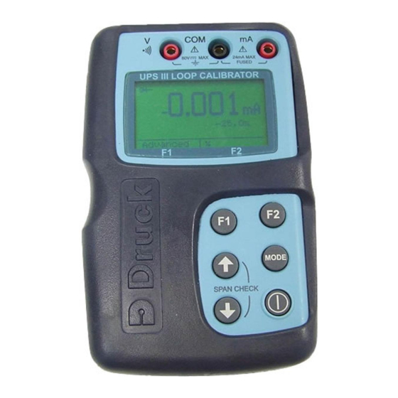
Druck UPS-III Loop Calibrator
User manual -K0317
Test Equipment Depot — 800.517.8431
99 Washington Street, Melrose, MA 02176
TestEquipmentDepot.com
Related Manuals for GE Druck UPS-III
Summary of Contents for GE Druck UPS-III
-
Page 1
Sensing Druck UPS-III Loop Calibrator User manual -K0317 Test Equipment Depot — 800.517.8431 99 Washington Street, Melrose, MA 02176 TestEquipmentDepot.com… -
Page 2
Symbols This equipment meets the requirements of all relevant European safety directives. The equipment carries the CE mark. This symbol, on the instrument, indicates that the user should refer to the user manual. Do not dispose of this product as household waste. -
Page 3
UPS III Loop Calibrator Introduction The Druck UPS III Series of loop calibrators can supply power (source mode) and produce readings (measure mode) to perform field calibrations on 2-wire devices. The set-up menu enables the user to “source” or “measure” in either voltage or current and to perform continuity tests. -
Page 4
Physical Dimensions……77 x 129 x 24 mm(3” x 5” x 1”) Weight ……….275 grams (9.7 oz.) Terminals ……..4 mm sockets {gold plated} Case …………High impact ABS Relative Humidity………… 0 to 90% Safety This symbol, on the loop calibrator, indicates that the user should refer to the user guide or manual. -
Page 5
OPERATION Keys key switches the calibrator on and off. Press and hold for 2 seconds. key changes the measure or source operating mode. Pressing the keys makes menu selections, sets numerical values and controls step and ramp functions (up/down). select advanced functions shown on the bottom of the display. -
Page 6: Operating Modes
Operating Modes Pressing switches the instrument on and the display shows the start-up sequence. Pressing , at this time, the display shows the information screen: Information Serial number VERSION CAL. DATE HART BATTERY Pressing , at this time, the display shows the set-up screen: adjust Contrast adjust…
-
Page 7
Connect the loop calibrator to the device to be tested: Measure mA Press the mode key and select [Measure mA]. External power supplies Vmax = 60 V for the loop. The calibrator measures the current flow of the loop. Closed loop current measurement from transmitter test terminal. -
Page 8
Measure Volts Press mode key and select [Measure V], measure range 60V, maximum impedance 1 Mohm. Continuity Test Press mode key and select [Continuity Test]. Pressing switches the audible signal on/off. K0317 Issue No. 3… -
Page 9
Source Mode The display shows the source value in mA or % value of 4 to 20 mA or 0 to 20 mA, linear or flow depending on the settings made in set-up and advanced settings. Source mA Press mode key and select [Source mA]. The calibrator supplies maximum output of: 24 mA;… -
Page 10
Advanced Options in a Source mode Press the key and select mA Source or mA Source & 24V. MODE (Enter) to select the function. Press the key (Advanced) and the display shows: Linear simulates linear transmitters. Flow simulates flow transmitters. Valve simulates valve control signals. -
Page 11
Operation of Advanced Options Press the key to switch the advanced setting on and off: e.g. on or off Press step the output up or down. step the span check maximum or minimum start the “ramp”. Press then to start: continuous auto-step. -
Page 12
blank page K0317 Issue No. 3… -
Page 13: Maintenance
Maintenance • Return the loop calibrator to an authorised repair centre for any repairs, it cannot be repaired on-site. • To keep the loop calibrator accurate a calibration check should be carried out once per year. Cleaning • Clean the loop calibrator case with a moist, lint-free cloth and weak detergent.
-
Page 14: Battery Replacement
Battery Replacement Only use the battery type listed on page one. Unscrew and remove the securing screw from the battery panel. Replace the batteries, check the polarity of the batteries. Refit and secure the battery panel. K0317 Issue No. 3…
-
Page 15: Calibration Instructions
Calibration Instructions General The instrument is supplied by the manufacturer, complete with calibration certificate(s). A calibration period of 12 months is recommended. The actual calibration interval depends on instrument usage and the total measurement uncertainty acceptable for the specified application. The UPS-III is a very precise measuring instrument and the test equipment and conditions of test must be suitable for the type of work.
-
Page 16: Calibration Check
Table 2 V measure Applied V Permitted UPS-III error Calibrator error (mV) (mV) 0.004 0.00040 0.004 0.00014 0.005 0.00064 0.005 0.00070 UPS-III source mode Table 3 mA source Applied Permitted UPS-III error Calibrator error (mA) (mA) 0.002 0.002 0.00012 0.002 0.00011 0.002 0.00015…
-
Page 17: Calibration Adjustment
Calibration Adjustment 1.Connect the UPS-III to the electrical calibrator. Switch on the electrical calibrator and allow it to thermally stabilise. 2.Switch on the UPS-III and press , within two seconds to select Calibration. Enter the access code [9410 factory setting] and allow the instrument to thermally stabilise. 3.Select the parameter required for calibration.
-
Page 18
K0317 Issue No. 3… -
Page 19
K0317 Issue No. 3… -
Page 20
K0317 Issue No. 3…
Калибратор контуров Druck UPS-III

Введение
Искробезопасный калибратор контуров Druck UPS-III может подавать питание (режим источника) и производить показания (режим измерения) для выполнения полевых калибровок на 2-проводных устройствах. Меню настройки позволяет пользователю «исходить» или «измерять» в любом объеме.tage или ток и выполнить проверку непрерывности. В этих инструкциях подробно описаны требования и порядок работы искробезопасного калибратора контуров UPS-III в опасной зоне. Перед началом прочтите всю публикацию.
Сохранность
ИБП-III спроектирован таким образом, чтобы обеспечивать безопасность при эксплуатации в соответствии с процедурами, подробно описанными в данном руководстве. Не используйте это оборудование для каких-либо других целей, кроме указанных, защита, обеспечиваемая оборудованием, может быть нарушена.
Перед установкой и использованием ИБП-III прочтите и поймите все относящиеся к нему данные. Сюда входят: все местные процедуры безопасности и стандарты установки, а также этот документ.
Перед началом операции или процедуры используйте только сертифицированных инженеров, обладающих необходимыми навыками (при необходимости, с квалификацией утвержденного учебного заведения). Всегда следуйте хорошей инженерной практике.
Ремонт
Не ремонтируйте данное оборудование. Верните оборудование производителю или уполномоченному сервисному агенту.
Символы
Напряжение питания
Источником питания для этого калибратора петли могут быть внутренние неперезаряжаемые батареи или внешний универсальный блок питания, аксессуар Druck. ИОПСУ-1.
батареи
![]() ОСТОРОЖНО Не смешивайте типы ячеек. Не смешивайте старые и новые клетки.
ОСТОРОЖНО Не смешивайте типы ячеек. Не смешивайте старые и новые клетки.
Удалите элементы из устройства, если они помещены на хранение в течение длительного периода времени. Если в ячейке произошла утечка, верните устройство в авторизованный сервисный центр Druck.
Используйте только 4 первичных марганцевых щелочных элемента AA LR6.
Руководство по снабжению и вводу/выводу
Таблица 1: Ключ к условиям таблицы параметров сущности
| состояние | Описание |
|
❶&❷ |
Измерение тока между мА и COM при внешнем напряжении 24 В. Этот режим работы вводит аппарат в токовую петлю, разрывая цепь и подключая мА (положительный) и СОМ (отрицательный) к цепи. |
|
❸ |
Измерение тока между мА (24 В) и мА при внутреннем напряжении 24 В. Клемма мА (24В) обеспечивает питание для дистанционного датчика. Особое условие для безопасного использования – дистанционный датчик ДОЛЖЕН быть изолирован от всех других источников питания. |
| ❹ | Voltage измерение между V и COM. |
| ❺ | Измерение непрерывности между V и COM. Особое условие для безопасного использования – дистанционный датчик ДОЛЖЕН быть изолирован от всех других источников питания. |
|
❻ |
Генерация тока между мА и COM при внешнем напряжении 24 В. Этот режим работы вводит аппарат в токовую петлю, разрывая цепь и подключая мА (положительный) и СОМ (отрицательный) к цепи. |
|
❼ |
Генерация тока между мА (24 В) и мА с внутренним 24 В. Клемма мА (24 В) обеспечивает питание выносного датчика. Особое условие для безопасного использования – дистанционный датчик ДОЛЖЕН быть изолирован от всех других источников питания. |
Эксплуатация
Ключи
Наблюдения и советы этой статьи мы подготовили на основании опыта команды  включает и выключает калибратор петли. Нажмите и удерживайте в течение 2 секунд.
Наблюдения и советы этой статьи мы подготовили на основании опыта команды ![]() клавиша изменяет режим измерения или источника. Нажатие
клавиша изменяет режим измерения или источника. Нажатие ![]() Клавиши делают выбор в меню, устанавливают числовые значения и регулируют шаг и r.amp функции (вверх/вниз).
Клавиши делают выбор в меню, устанавливают числовые значения и регулируют шаг и r.amp функции (вверх/вниз).
Наблюдения и советы этой статьи мы подготовили на основании опыта команды ![]() выберите расширенные функции, показанные в нижней части дисплея. Если в течение 10 минут не будет нажата ни одна клавиша, время ожидания калибратора контура истекает, и он отключается. Чтобы отключить этот автоматический тайм-аут, выберите Aut power down в меню настройки.
выберите расширенные функции, показанные в нижней части дисплея. Если в течение 10 минут не будет нажата ни одна клавиша, время ожидания калибратора контура истекает, и он отключается. Чтобы отключить этот автоматический тайм-аут, выберите Aut power down в меню настройки.

Режимы работы
Прессование включает прибор, и на дисплее отображается последовательность запуска. Нажатие ![]() , в это время на дисплее отображается информационный экран:
, в это время на дисплее отображается информационный экран:
Прессование  , в это время на дисплее отображается экран настройки:
Калибратор можно использовать в двух режимах измерения или источника.
Режим измерения
На дисплее отображается измеренное значение; в зависимости от настроек, сделанных в настройках и дополнительных настройках:
При измерении тока нажатия ![]() включает линейный или поток, нажав включает мА или % (значение от 4 до 20 мА или от 0 до 20 мА).
включает линейный или поток, нажав включает мА или % (значение от 4 до 20 мА или от 0 до 20 мА).
При измерении объемаtage нажатие изменяет разрешение между 0.00 В и 0.000 В.
Для измерения непрерывности на дисплеях отображается символ разомкнутого или замкнутого переключателя со звуковым сигналом при замыкании переключателя. Подключите калибратор к тестируемому устройству:
Измерить мА ❶
Нажмите Режим и выберите [Измерить мА]. Внешний источник питания обеспечивает максимальное напряжение 60 В для контура. Калибратор измеряет ток контура.
Измерить мА ❷
Измерение тока в замкнутом контуре с тестового терминала передатчика.
Измерение мА с 24 В ❸
Нажмите кнопку режима и выберите [Измерить мА и 24 В]. Калибратор подает 24 В (максимум) на контур, максимум 24 мА.
Измерение вольт ❹
Нажмите кнопку режима и выберите [Измерение напряжения], диапазон измерения 60 В, максимальное сопротивление 1 МОм.
Тест на непрерывность ❺
Нажмите Режим и выберите [Проверка непрерывности]. Нажатие включает/выключает звуковой сигнал.
Исходный режим
На дисплее отображается исходное значение в мА или % от 4 до 20 мА или от 0 до 20 мА, линейное или расходное, в зависимости от настроек, сделанных в настройках и дополнительных настройках.
Источник мА ❻
Нажмите кнопку режима и выберите [Источник мА]. Калибратор обеспечивает максимальный выходной сигнал: 24 мА; Vмакс = 60 В; вход приемника Rmax = 1 кОм.
Источник мА с 24 В ❼
Нажмите Режим и выберите [Источник мА и 24 В]. Калибратор обеспечивает питание контура: 24 В и 24 мА.
Дополнительные параметры в исходном режиме
Нажмите ![]() и выберите Источник мА или Источник мА и 24 В.
и выберите Источник мА или Источник мА и 24 В.
Используйте ![]() и (Enter), чтобы выбрать функцию.
и (Enter), чтобы выбрать функцию.
Нажмите  нажмите клавишу (Дополнительно), и на дисплее появится:
- «Линейный» имитирует линейные передатчики.
- «Flow» имитирует датчики расхода.
- «Valve» имитирует сигналы управления клапаном.
Используйте ![]() и (Enter), чтобы выбрать расширенный вариант:
и (Enter), чтобы выбрать расширенный вариант:
Таблица 2: Дополнительные параметры
| Опция | Описание |
| Степ-аэробика | Шаги 25% для линейного и расходного – фиксированные значения для клапана. |
| Автошаг | То же, что шаг с временным интервалом шага. |
| Проверка диапазона | Шаг между 4 (или 0) мА и 20 мА. |
| Ramp | Автоматическая рamp от 4 (или 0) мА до 20 мА. |
Примечание: Ramp функция недоступна для выбора клапана.
Используйте бросить. Дисплей возвращается к выбранному режиму источника
с доступными расширенными настройками.
Exampле Операция
Нажмите для включения и выключения расширенных настроек:
например ![]() вкл или выкл
вкл или выкл
Нажмите ![]() or
or ![]() чтобы:
чтобы:
а. увеличить или уменьшить вывод.
б. Шаг проверки диапазона максимум или минимум.
в. начать «рamp».
Нажмите ![]() становятся
становятся ![]() начать:
начать:
а. непрерывный автошаг.
or
б. непрерывный рamp в первом цикле (свежий перенос эмбрионов).
Приложение Харт®
Это приложение позволяет использовать режимы измерения мА и источника через коммуникатор Hart®.
- Коммуникатор Hart®.
- Резистор контура 220 Ом, выбираемый в меню ИБП-III
Обслуживание
- Верните калибратор контура в авторизованный ремонтный центр для любого ремонта, он не может быть отремонтирован на месте.
- Для обеспечения точности калибратора контура необходимо проводить проверку калибровки один раз в год.
Уборка
- Очистите корпус калибратора петли влажной безворсовой тканью и слабым моющим средством.
Замена батареи
 Этот символ указывает на то, что батареи разряжены, замените их, соблюдая полярность, указанную ниже.
Отвинтите и снимите крепежный винт с панели аккумуляторного отсека. Замените батареи, проверьте полярность батарей. Установите и закрепите панель аккумулятора.
Извлекайте батареи из калибратора петли сразу после разрядки и перед хранением.
Утилизируйте аккумуляторы в соответствии с местными нормами и инструкциями производителей аккумуляторов.
При хранении и транспортировке батарей следите за тем, чтобы в них не произошло короткое замыкание.
Калибровка
Прибор поставляется производителем вместе с сертификатом(ами) калибровки.
Рекомендуемый период калибровки 12 месяцев. Фактический интервал калибровки зависит от использования прибора и общей неопределенности измерений, приемлемой для конкретного применения.
UPS-III является очень точным измерительным прибором, поэтому испытательное оборудование и условия испытаний должны соответствовать типу работы. Проверка калибровки и корректировка калибровки должны выполняться в контролируемой среде специалистом по калибровке*
Производитель предлагает комплексную услугу по калибровке, при необходимости аккредитованную UKAS.
Калибровочное оборудование
В следующих таблицах приведены требования к точности калибровочного оборудования и ИБП-III.
Для калибровки требуется стабильная температура 21° ± 1°C (70° ± 2°F).
Режим измерения ИБП-III
Таблица 3: Измерение мА
| Приложенный мА | Допустимая ошибка ИБП-III (мА) | Ошибка калибратора (мА) |
| 0 | 0.002 | 0 |
| 4 | 0.002 | 0.00014 |
| 12 | 0.002 | 0.00030 |
| 20 | 0.002 | 0.00046 |
Таблица 4: Измерение V
| Прикладной V | Допустимая ошибка ИБП-III (мВ) | Ошибка калибратора (мВ) |
| 0 | 0.004 | 0.00040 |
| 20 | 0.004 | 0.00014 |
| 40 | 0.005 | 0.00064 |
| 50 | 0.005 | 0.00070 |
Техник по калибровке должен иметь необходимые технические знания, документацию, специальное испытательное оборудование и инструменты для проведения калибровочных работ на этом оборудовании.
Режим источника ИБП-III
Таблица 5: Источник мА
| Приложенный мА | Допустимая ошибка ИБП-III (мА) | Ошибка калибратора (мА) |
| 0 | 0.002 | 0 |
| 4 | 0.002 | 0.00012 |
| 12 | 0.002 | 0.00011 |
| 20 | 0.002 | 0.00015 |
Проверка калибровки
1. Подключите ИБП-III к электрическому калибратору. Включите электрический калибратор и дайте ему термически стабилизироваться.
2. Включите ИБП-III и дайте прибору стабилизироваться.
3. Установите ИБП-III на измерение мА, отрегулируйте электрический калибратор, чтобы применить первое значение в Таблице 3. Запишите показания ИБП-III.
4. Повторите шаг 3 для всех значений в таблице 3.
5. Сравните записанные значения и примененные значения, если разница превышает допустимую погрешность, прибор требует корректировки калибровки.
6. Повторите эту процедуру для измерения напряжения (таблица 4) и источника мА (таблица 5).
Калибровка Регулировка
 ИНФОРМАЦИЯ Для ИБП-III требуется двухточечный калибровка в диапазоне В и мА.
- Подключите ИБП-III к электрическому калибратору. Включите электрический калибратор и дайте ему термически стабилизироваться.
- Включите ИБП-III и нажмите
 , в течение двух секунд выберите Калибровка. Введите код доступа [заводская настройка 9410] и дождитесь термостабилизации прибора.
 - Выберите параметр, необходимый для калибровки. Используйте меню дисплея для выбора значений калибровки. После успешной калибровки введите новую дату калибровки


Спецификация
Таблица 6: Физические характеристики
| Товары | Спецификация |
| Габаритные размеры: | 77 x 129 x 24 мм (3 «x 5» x 1 «) |
| Вес (номинальный) | 275 г (9.7 унции) |
| Разъемы | Розетки 4 мм |
| Коробка | Ударопрочный ABS |
| Экологические исследования георадаром | IP40 |
| Относительная влажность | 0 в 90% |
Таблица 7: Общие характеристики
| Товары | Спецификация |
| Точность на один год | 17 ° С до 27 ° C (63 ° F до 81 ° F) |
| Вне этих пределов | 0.003%/°C (0.0015%/°F) |
| Справка | 22°С ± 1°С; Относительная влажность 45% ± 15% |
| Срок службы батареи | ≥ 75 часов в режиме измерения ≥ 18 часов при 12 мА в режиме источника |
| Связь Харт® | Выбираемый в меню резистор контура 220 Ом |
| Рабочая Температура | -10 ° C до 50 ° C (14 ° F до 122 ° F) |
| Температура хранения | -20 ° C до 70 ° C (-4 ° F до 158 ° F) |
Таблица 8: Спецификация точности
| режим | Диапазон | Постановления | точностьa |
| Источник мА | от 0 до 24 мАт | 0.001 | 0.01% показаний + 2 фунта стерлингов |
| Источник мА + 24В | от 0 до 24 мАч | 0.001 | 0.01% показаний + 2 фунта стерлингов |
| Измерить мА | от 0 до 24 мАт | 0.001 | 0.01% показаний + 2 фунта стерлингов |
| Измерить мА + 24 В | от 0 до 24 мАд | 0.001 | 0.01% показаний + 2 фунта стерлингов |
| Мера V | от 0 до 60 Ве | 0.001 | 0.02% показаний + 4 фунта стерлингов |
| непрерывность | <100 Омф | – | – |
а. rdg = чтение, lsd = младшие значащие цифры.
б. В максимальное = 75В.
в. R максимум 1 кОм при 20 мА.
д. R мера = 15 Ом.
е. Измерение R > 1 МОм.
ф. Звуковая и визуальная индикация, испытательный ток 1 мА
Процедура возврата товаров/материалов
Если устройство требует калибровки или неисправно, верните его в ближайший сервисный центр Druck, указанный на странице: Druck.com/essential.
Обратитесь в отдел обслуживания, чтобы получить разрешение на возврат товаров/материалов (RGA или RMA). Предоставьте следующую информацию для RGA или RMA:
- Продукт (т.е. ИБП-III)
- Серийный номер.
- Подробная информация о дефекте/работах, которые необходимо выполнить.
- Требования к прослеживаемости калибровки.
- Условия эксплуатации.
Авторские права принадлежат компании Бейкер Хьюз, 2003 г. Этот материал содержит один или несколько зарегистрированных товарных знаков компании Baker Hughes и ее дочерних компаний в одной или нескольких странах. Все сторонние названия продуктов и компаний являются товарными знаками соответствующих владельцев.

Документы / Ресурсы
-
Bookmarks
Quick Links
GE
Sensing
Druck UPS-III Loop Calibrator
User manual -K0317
0.561.8187
information@itm.
www.
.com
Related Manuals for GE Druck UPS-III
Summary of Contents for GE Druck UPS-III
-
Page 1
Sensing Druck UPS-III Loop Calibrator User manual -K0317 0.561.8187 information@itm. www. .com… -
Page 2
Approved Service Agents Symbols This equipment meets the requirements of all relevant European safety directives. The equipment carries the CE mark. This symbol, on the instrument, indicates that the user should refer to the user manual. Do not dispose of this product as household waste. -
Page 3
UPS III Loop Calibrator Introduction The Druck UPS III Series of loop calibrators can supply power (source mode) and produce readings (measure mode) to perform field calibrations on 2-wire devices. The set-up menu enables the user to “source” or “measure” in either voltage or current and to perform continuity tests. -
Page 4
Physical Dimensions……77 x 129 x 24 mm(3” x 5” x 1”) Weight ……….275 grams (9.7 oz.) Terminals ……..4 mm sockets {gold plated} Case …………High impact ABS Relative Humidity………… 0 to 90% Safety This symbol, on the loop calibrator, indicates that the user should refer to the user guide or manual. -
Page 5
OPERATION Keys key switches the calibrator on and off. Press and hold for 2 seconds. key changes the measure or source operating mode. Pressing the keys makes menu selections, sets numerical values and controls step and ramp functions (up/down). select advanced functions shown on the bottom of the display. -
Page 6
Operating Modes Pressing switches the instrument on and the display shows the start-up sequence. Pressing , at this time, the display shows the information screen: Information Serial number VERSION CAL. DATE HART BATTERY Pressing , at this time, the display shows the set-up screen: adjust Contrast adjust… -
Page 7
Connect the loop calibrator to the device to be tested: Measure mA Press the mode key and select [Measure mA]. External power supplies Vmax = 60 V for the loop. The calibrator measures the current flow of the loop. Closed loop current measurement from transmitter test terminal. -
Page 8
Measure Volts Press mode key and select [Measure V], measure range 60V, maximum impedance 1 Mohm. Continuity Test Press mode key and select [Continuity Test]. Pressing switches the audible signal on/off. K0317 Issue No. 3 0.561.8187 information@itm. www. .com… -
Page 9
Source Mode The display shows the source value in mA or % value of 4 to 20 mA or 0 to 20 mA, linear or flow depending on the settings made in set-up and advanced settings. Source mA Press mode key and select [Source mA]. The calibrator supplies maximum output of: 24 mA;… -
Page 10
Advanced Options in a Source mode Press the key and select mA Source or mA Source & 24V. MODE (Enter) to select the function. Press the key (Advanced) and the display shows: Linear simulates linear transmitters. Flow simulates flow transmitters. Valve simulates valve control signals. -
Page 11
Operation of Advanced Options Press the key to switch the advanced setting on and off: e.g. on or off Press step the output up or down. step the span check maximum or minimum start the “ramp”. Press then to start: continuous auto-step. -
Page 12
Maintenance • Return the loop calibrator to an authorised repair centre for any repairs, it cannot be repaired on-site. • To keep the loop calibrator accurate a calibration check should be carried out once per year. Cleaning • Clean the loop calibrator case with a moist, lint-free cloth and weak detergent. -
Page 13
Battery Replacement Only use the battery type listed on page one. Unscrew and remove the securing screw from the battery panel. Replace the batteries, check the polarity of the batteries. Refit and secure the battery panel. K0317 Issue No. 3 0.561.8187 information@itm. -
Page 14
Calibration Instructions General The instrument is supplied by the manufacturer, complete with calibration certificate(s). A calibration period of 12 months is recommended. The actual calibration interval depends on instrument usage and the total measurement uncertainty acceptable for the specified application. The UPS-III is a very precise measuring instrument and the test equipment and conditions of test must be suitable for the type of work. -
Page 15
Table 2 V measure Applied V Permitted UPS-III error Calibrator error (mV) (mV) 0.004 0.00040 0.004 0.00014 0.005 0.00064 0.005 0.00070 UPS-III source mode Table 3 mA source Applied Permitted UPS-III error Calibrator error (mA) (mA) 0.002 0.002 0.00012 0.002 0.00011 0.002 0.00015… -
Page 16
Calibration Adjustment 1.Connect the UPS-III to the electrical calibrator. Switch on the electrical calibrator and allow it to thermally stabilise. 2.Switch on the UPS-III and press , within two seconds to select Calibration. Enter the access code [9410 factory setting] and allow the instrument to thermally stabilise. 3.Select the parameter required for calibration. -
Page 17
K0317 Issue No. 3 0.561.8187 information@itm. www. .com… -
Page 18
K0317 Issue No. 3 0.561.8187 information@itm. www. .com… -
Page 19
K0317 Issue No. 3 0.561.8187 information@itm. www. .com…
User Manual UPS III Loop Calibrator
English 1 — 12
Français 13 — 24
Deutsch 25 — 36
Italiano 37- 48
Español 49 — 60
Português 61 — 72
K317
UPS III Loop Calibrators
Introduction
The Druck UPS III Series of loop calibrators can supply power (source mode) and produce readings
(measure mode) to perform field calibrations on 2wire devices. The set-up menu enables the user to
“source” or “measure” in either voltage or current and to perform continuity tests. These user instructions include the operation, safety instructions and installation requirements for loop calibrators.
Specifications
Accuracy
Values in table below includes temperature effects 17°C to 27°C
Outside these limits ……………… 0.003%/°C(0.0015%/F°)
Calibration Reference……………. 22°C ±1°C/RH45%±15%
Mode Range Accuracy Remarks
Source mA
Source mA +
24V
0 to 24 mA* 0.01% rdg + 2 lsd V-max. 75V
0 to 24 mA* 0.01% rdg + 2 lsd R-max 1k
Ω
at 20 mA
Measure mA 0 to 24 mA* 0.01% rdg + 2 lsd V-max. 75V
Measure mA
+ 24V
Measure V
Continuity
0 to 24 mA* 0.01% rdg + 2 lsd R-measure
0 to 60V*
<100
Ω **
—
15
Ω
0.02% rdg + 4 lsd R-measure
1M
Ω
1 mA
* Resolution 0.001
**
Audio + visual lsd least significant digits rdg reading
Operating Temperature…… -10°C to 50°C (-14°F to 122°F)
Storage Temperature……… -20°C to 70°C (-4°F to 158°F)
This loop calibrator meets the essential protection requirements of the relevant EEC directives.
Conforms to ……… EN61010, EN 61326-1(1997)+ A1(1998)
Electrical Power Supply
……………………………… 4 x 1.5 V alkaline size AA or
Universal power supply {see accessories}
1 K317 Issue No. 1
Physical
Dimensions……………………. 77 x 129 x 24 mm(3” x 5” x 1”)
Weight ……………………………………… 275 grams (0.6 lbs)
Terminals …………………………….4 mm sockets {gold plated}
Case ………………………………………………. High impact ABS
Relative Humidity……………………………………………. 0 to 90%
Safety
This symbol, on the loop calibrator, indicates that the user should refer to the user guide or manual.
Batteries
• Remove batteries from the loop calibrator immediately when discharged and before storage.
• Dispose of batteries in accordance with local regulations and battery manufacturers’ instructions.
• When storing and transporting batteries make sure they cannot be short circuited.
Power Supply
The power supply for this loop calibrator can be the internal non-rechargeable batteries or the external Universal power supply unit (see accessories).
Battery life
The display shows
> 75 hours in measure mode
> 18 hours at 12 mA (source mode)
with low battery power.
Battery Replacement
• Unscrew and remove the securing screw from the battery panel.
• Replace the batteries, check the polarity of the batteries.
• Refit and secure the battery panel.
Accessories
Assy 305 Test lead set
191-129 Power supply, Universal, 100-240 V a.c. 47-63Hz
38016 Carrying case
38023 Protective rubber boot
K317 Issue No. 1 2
OPERATION
Keys
The key switches the calibrator on and off. Press and hold for 2 seconds.
The key changes the measure or source operating mode. Pressing the keys makes menu selections, sets numerical values and controls step and ramp functions (up/down).
The select advanced functions shown on the bottom of the display. When no key is pressed for 10 minutes, the calibrator times out and switches off. To disable this automatic time out, select autpower down in the set-up menu.
Operating Modes
The calibrator can be used in two modes measure or source.
Measure mode
The display shows the measured value in mA or % value of 4 to 20 mA or 0 to 20 mA, linear or flow depending on the settings made in set-up and advanced settings. In this mode continuity can be shown by an open or closed switch symbol with an audible signal on switch closed.
Connect the loop calibrator to the device to be tested:
3 K317 Issue No. 1
Press the mode key and select [Measure mA]. External power supplies Vmax = 60 V for the loop. The calibrator measures the current flow of the loop.
Closed loop current measurement from transmitter test terminal
* test terminal
Measure mA with 24 V
Press mode key and select [Measure mA and 24V]. The calibrator supplies 24 V for the loop, maximum 24 mA
K317 Issue No. 1 4
Measure Volts
Press mode key and select [Measure V], measure range
60V, maximum impedance 1 Mohm.
Continuity Test
Press mode key and select [Continuity Test].
Pressing switches the audible signal on/off.
5 K317 Issue No. 1
Source Mode
The display shows the source value in mA or % value of 4 to
20 mA or 0 to 20 mA, linear or flow depending on the settings made in set-up and advanced settings.
Source mA
Press mode key and select [Source mA]. The calibrator supplies maximum output of: 24 mA; Vmax = 60; receiver input Rmax = 1kOhm.
Source mA with 24V
Press mode key and select [Source mA and 24V]. The calibrator supplies maximum loop power of: 24 V and 24 mA.
K317 Issue No. 1 6
Advanced options in Source mode
Press the key to enter advanced options:
Linear simulates linear transmitters.
Flow
Valve simulates flow transmitters.
simulates valve control signals.
Note: Ramp function not available for Valve selection.
Step 25% steps for linear and flow — fixed values for
Valve.
The same as step with a timed step interval.
Auto-step
Span Check Step between 4(or 0)mA and 20 mA.
Ramp Automatic ramp between 4(or 0)mA and 20 mA.
Maintenance
• Return the loop calibrator to the factory for any repairs, it cannot be repaired on-site.
• To keep the loop calibrator accurate a calibration check should be carried out once per year.
Cleaning
• Clean the loop calibrator case with a moist, lint-free cloth and weak detergent.
7 K317 Issue No. 1
Calibration Instructions
1.Use an electrical calibrator that has an accuracy three times better than the UPS III. Connect the UPS III to the calibrator.
2.Switch on the instrument and press , within two seconds to select Calibration. Enter the access code [9410 factory setting] and select the parameter required for calibration.
3.Use the display menu to select the calibration values. After a successful calibration enter the new calibration date.
K317 Issue No. 1 8
9 K317 Issue No. 1
K317 Issue No. 1 10
11 K317 Issue No. 1
K317 Issue No. 1 12
Calibrateurs de boucle UPS III
Introduction
La série Druck UPS III de calibrateurs de boucle est en mesure de fournir une alimentation électrique (mode
source) et de produire des relevés (mode mesure) afin de réaliser un étalonnage sur place des appareils bifilaires. Le menu de configuration permet à l’utilisateur de sélectionner
« source » ou « mesure » pour tous les courants et tensions et d’effectuer des essais de continuité.
Ces consignes d’utilisation comprennent les consignes de fonctionnement et de sécurité, ainsi que les conditions d’installation des calibrateurs de boucle.
Spécifications
Précision
Les valeurs du tableau ci-dessous comprennent les effets thermiques 17°C à 27°C.
Hors de ces limites………………0,003 %/°C (0,0015 %/F°)
Référence d’étalonnage…………22°C ±1°C/RH45 %±15 %
Mode
Source mA
Gamme
0 à 24 mA*
Précision Remarques
Source mA +
24V
0 à 24 mA*
Measure mA 0 à 24 mA*
Measure mA +
24V
0 à 24 mA*
Measure V
0 à 60 V*
Continuité
<100 W **
*
Résolution 0,001
**
Audio + visuel
0,01 % rel + 2 bfp Tension max.
75 V
0,01 % rel + 2 bfp Résistance max
1 k
Ω à 20 mA
0,01 % rel + 2 bfp Tension max.
75 V
0,01 % rel + 2 bfp Mesure Résistance 15
Ω
0,02 % rel + 4 bfp
Mesure Résistance 1 M
Ω
1 mA bfp bit de plus faible poids rel relevé
Température de fonctionnement
Température de stockage
………….. …………………………….. -20°C à 70°C (-4°F à 158°F)
13 K317 Edition No. 1
Ce calibrateur est conforme aux exigences essentielles des directives CE correspondantes concernant la protection.
Conforme à……….EN61010, EN 61326-1(1997)+ A1(1998)
Alimentation électrique
………………………………………… Pile 4 x 1,5 V alcaline AA ou
Alimentation universelle (voir accessoires)
Caractéristiques physiques
Dimensions……………… 77 x 129 x 24 mm (3” x 5” x 1”)
Poids………………. …………………… 275 grammes (0,6 lbs)
Boîtier……………………….. Plastique ABS très résistant
Humidité relative………………………………………….. 0 à 90 %
Sécurité
Ce symbole, sur le calibrateur de boucle, indique que l’utilisateur doit consulter le manuel d’utilisation.
Piles
• Enlevez les piles du calibrateur dès qu’elles sont déchargées et avant le stockage.
• Disposez des piles conformément aux règlements locaux et aux consignes du fabricant.
• Lors de l’entreposage et du transport des piles, veillez à ce qu’elles ne puissent pas se court-circuiter.
Alimentation
La calibrateur peut être alimenté par des piles internes non rechargeables ou par un bloc d’alimentation universel externe (voir accessoires).
Autonomie des piles > 75 heures en mode de mesure
> 18 heures à 12 mA (en mode source)
L’affichage indique lorsque les piles sont faibles.
K317 Edition No. 1 14
Changement des piles
• Dévissez et retirez la vis fixant le panneau des piles.
• Remplacez les piles en veillant à respecter la polarité.
• Replacez et revissez le panneau des piles.
Accessoires
Assy 305 Jeu de fils d’essai
191-129 Alimentation, universelle 100-240 V c.a. 47-
63 Hz
38016
38023
Sacoche
Gaine de protection en caoutchouc
15 K317 Edition No. 1
FONCTIONNEMENT
Touches
La touche permet de mettre le calibrateur sous ou hors tension.
Appuyez dessus pendant 2 secondes.
La touche permet de basculer entre le mode de mesure et le mode source. Les touches permettent d’effectuer les sélections dans les menus, de paramétrer les valeurs numériques et de contrôler les fonctions de pas et de rampe (haut/bas)
Fonctions avancées présentées en bas de l’affichage. Lorsqu’aucune touche n’est utilisée pendant 10 minutes, le calibrateur se met automatiquement hors tension. Pour désactiver cette temporisation, sélectionnez
autpower down dans le menu de configuration.
Modes de fonctionnement
Le calibrateur dispose de deux modes mesure et source.
Mode de mesure
L’affichage indique la valeur mesurée en mA ou un % de 4 à
20 mA ou de 0 à 24 mA, linéaire ou débit selon les paramètres configurés. Dans ce mode, la continuité est indiquée par le symbole d’un interrupteur, fermé ou ouvert, avec un signal sonore sur fermeture de l’interrupteur.
Connectez le calibrateur à l’appareil à tester :
K317 Edition No. 1 16
Appuyez sur la touche mode puis sélectionnez [Measure mA]. Bloc d’alimentation externe Tension max = 60 V pour la boucle. Le calibrateur mesure le débit actuel de la boucle.
Mesure du courant dans la boucle fermée depuis la borne de test de l’émetteur
* test terminal
Mesurez mA avec 24 V
Appuyez sur la touche mode puis sélectionnez [Measure mA and 24 V]. Le calibrateur fournit 24 V pour la boucle, maximum 24 mA
17 K317 Edition No. 1
Mesurez la tension
Appuyez sur la touche mode puis sélectionnez [Measure V], mesurez la gamme 60 V, impédance maximale 1 Mohm.
Test de continuité
Appuyez sur la touche mode puis sélectionnez [Continuity
Test].
La touche permet d’activer/de désactiver le signal sonore.
K317 Edition No. 1 18
Mode source
L’affichage indique la valeur source en mA ou en pourcentage de 4 à 20 mA ou de 0 à 20 mA, linéaire ou débit selon les paramètres configurés.
Source mA
Appuyez sur la touche mode puis sélectionnez [Source mA].
Le calibrateur fournir une sortie maximale de : 24 mA ; tension max = 60 ; résistance max entrée récepteur =
1 kOhm
Source mA avec 24 V
Appuyez sur la touche mode puis sélectionnez [Source mA and 24 V]. Le calibrateur fournir une puissance boucle maximale de : 24 V et 24 mA.
19 K317 Edition No. 1
Options avancées en mode Source
Appuyez sur la touche pour définir les options avancées:
Linear
Flow
Valve simule des émetteurs linéaires.
simule des émetteurs de débit.
simule les signaux de commande de vanne.
Remarque : la fonction Ramp n’est pas disponible avec la sélection Valve.
Step Pas de 25 % pour fonctions linéaire et débit – valeurs fixes pour fonction vanne.
Auto-step Identique à pas avec intervalle chronométré.
Span Check Pas entre 4 (ou 0) mA et 20 mA.
Ramp Rampe automatique entre 4 (ou 0) mA et
20 mA.
Entretien
• Renvoyez le calibrateur de boucle à l’usine pour être réparé, il ne peut pas être réparé sur place.
• Pour que le calibrateur fournisse des mesures exactes, un contrôle d’étalonnage doit être réalisé une fois par an.
Nettoyage
Nettoyer le boîtier du calibrateur au moyen d’un linge humide non pelucheux et d’un détergent doux.
20 K317 Edition No. 1
Consignes d’étalonnage
1.
Utilisez un calibrateur électrique dont la précision est trois fois supérieure à UPS III. Branchez l’UPS III au calibrateur.
2.
Mettez l’instrument sous tension puis appuyez, , dans les deux secondes, pour sélectionner l’étalonnage.
Entrez le code d’accès [9410 paramètre d’usine], puis sélectionnez le paramètre requis pour l’étalonnage.
3.
Utilisez le menu d’affichage pour sélectionner les valeurs d’étalonnage. Une fois l’étalonnage terminé, entrez la nouvelle date d’étalonnage.
K317 Edition No. 1 21
22 K317 Edition No. 1
K317 Edition No. 1 23
24 K317 Edition No. 1
UPS III Stromschleifenkalibrator
Einführung
Die Stromstreifenkalibratoren der Serie UPS III von
Druck können Schleifen speisen (Geben-Modus) und messen (Messen-Modus), um Geräte mit 2-
Leiteranschluss vor Ort zu kalibrieren. Das Setup-
Menü erlaubt dem Anwender die Einstellung auf
“Geben” oder “Messen” von Spannungen oder Strömen sowie das Ausführen von Durchgangstests. Diese
Bedienungsanleitung beschreibt Bedienung,
Sicherheitshinweise und Installationsbedingungen für
Schleifenkalibratoren.
Spezifikationen
Genauigkeit
Die folgende Tabelle bezieht sich auf 17°C bis 27°C.
Außerhalb dieser Grenzen…….. 0,003%/°C(0,0015%/F°)
Kalibrierungsreferenz……………. 22°C ±1°C/r. F. 45% ±15%
Modus Bereich Fehlergrenz Bemerkung
Geben mA
Geben mA +
24 V
0 bis 24 mA*
0 bis 24 mA*
Messen mA 0 bis 24 mA*
0,01% v. MW
+ 2 dig
0,01% v. MW
+ 2 dig
Messen mA +
24 V
0 bis 24 mA*
Messen V
Durchgang
0,01% v. MW
+ 2 dig
0,01% v. MW
+ 2 dig
0 bis 60 V* 0,02% v. MW
+ 4 dig
<100
Ω **
—
**
Optisch + akustisch
V max. 75 V
R max 1k
Ω
bei 20 mA
V max. 75 V
Rmess 15
Ω
Rmess 1 M
1 mA
dig Digits v. MW von Messwert
Ω
Betriebstemperatur
Lagertemperatur…
-10°C bis 50°C (-14°F bis 122°F)
-20 bis 70 °C (-4 bis 158 °F)
Dieser Stromschleifenkalibrator erfüllt die grundlegenden Schutzanforderungen der entsprechenden EU-Richtlinien.
25 K317 Ausgabe Nr. 1
Erfüllt ……………… EN 61326-1(1997)+ A1(1998)
Spannungsversorgung
…………………………….. 4 X 1,5 V Alkalizellen AA oder
Universal-Netzteil {S. Abschnitt Zubehör}
Mechanische Kennwerte
Abmessungen………………… 77 × 129 × 24 mm (3” × 5” × 1”)
Gewicht …………………………………….. 275 g (0,6 lbs)
Elektrische Anschlüsse ………….4 mm-Buchsen {vergoldet}
Gehäuse ………………………………………….. Schlagfestes ABS
Relative Feuchte…………………………………………….. 0 bis 90%
Sicherheit
Dieses Symbol auf dem Stromschleifenkalibrator verweist den Benutzer auf die
Bedienungsanleitung oder das Handbuch.
Batterien
• Entnehmen Sie die Batterien aus dem
Stromschleifenkalibrator, sobald diese entladen sind oder bevor Sie das Instrument lagern.
• Beachten Sie bei der Entsorgung der Batterien alle einschlägigen Vorschriften sowie die Anweisungen des
Batterieherstellers.
• Achten Sie darauf, dass Batterien bei Lagerung oder
Transport nicht kurzgeschlossen werden.
Spannungsversorgung
Die Versorgung des Stromschleifenkalibrators kann über die internen, nicht wieder aufladbaren Batterien oder über ein externes Universal-Netzteil erfolgen (s. Zubehör).
Batterielebensdauer > 75 Stunden im Messen-Modus
> 18 Stunden bei 12 mA (Geben-
Modus)
Bei zu niedriger Batteriespannung erscheint im Display das
Symbol .
Austausch der Batterien
• Lösen und entfernen Sie die Schraube von der
Batterieabdeckung.
• Tauschen Sie die Batterien aus. Beachten Sie dabei die
Polarität der Batterien.
K317 Ausgabe Nr. 1 26
• Befestigen und sichern Sie die Batterieabdeckung wieder.
Zubehör
Assy 305 Prüfkabelsatz
191-129 Universal-Netzteil, 100-240 V AC. 47-63 Hz
38016 Tragetasche
38023 Gummistoßschutz
BEDIENUNG
Tasten
Die Taste schaltet den Kalibrator ein und aus. Halten Sie die Taste für 2
Sekunden gedrückt.
Die Taste wechselt zwischen
Geben- und Messen-Modus. Die
Tasten dienen zur Auswahl in
Menüs, Einstellung numerischer
Werte und Steuerung der Schritt- und
Rampenfunktionen (auf/ab).
Die Tasten wählen die unten im Display angegebenen erweiterten Funktionen. Wenn für 10 Minuten keine Taste betätigt wurde, schaltet sich das Kalibrator automatisch ab. Um diese automatische Abschaltung zu deaktivieren, wählen Sie autpower down im Setup-Menü.
Betriebsarten
Der Kalibrator kann in den Betriebarten Geben und Messen betrieben werden.
Messen-Modus
Im Display wird je nach den im Setup vorgenommene
Einstellungen der Messwert in mA und in % angezeigt.
Verbinden Sie den Stromschleifenkalibrator wie folgt mit dem zu prüfenden Gerät:
27 K317 Ausgabe Nr. 1
Betätigen Sie die Modus-Taste und wählen Sie [Measure mA]. Externe Speisung der Schleife Vmax = 60 V. Der
Kalibrator misst den in der Schleife fließenden Strom.
Messung des Schleifenstroms über Test-Klemme des
Transmitters
* Test-Klemme
Messen: mA mit 24 V
Betätigen Sie die Modus-Taste und wählen Sie [Measure mA und 24 V]. Der Kalibrator speist die Schleife mit 24 V
(maximal 24 mA).
K317 Ausgabe Nr. 1 28
Messen: Volt
Betätigen Sie die Modus-Taste und wählen Sie [Measure V] für Messungen bis 60 V (maximale Impedanz 1 MOhm).
Durchgangstest
Betätigen Sie die Modus-Taste und wählen Sie [Continuity].
Die Taste schaltet das akustische Signal ein oder aus.
29 K317 Ausgabe Nr. 1
Geben-Modus
Im Display wird je nach den im Setup vorgenommenen
Einstellungen der ausgegebene Wert in mA und in % angezeigt.
Geben mA
Betätigen Sie die Modus-Taste und wählen Sie [Source mA].
Der Kalibrator gibt ein Ausgangssignal von maximal 24 mA bei Vmax = 60 V an eine Bürde von Rmax = 1 kOhm aus.
Geben mA mit 24 V
Betätigen Sie die Modus-Taste und wählen Sie [Source mA und 24 V]. Der Kalibrator speist die Schleife mit 24 V und gibt maximal 24 mA aus.
K317 Ausgabe Nr. 1 30
Erweiterte Optionen im Geben-Modus
Betätigen Sie die -Taste, um die erweiterten Optionen aufzurufen:
Lin simuliert lineare Transmitter.
Flow simuliert Durchfluss-Transmitter.
Valve simuliert Stellsignale für Ventil.
Anmerkung: Die Rampenfunktion ist für die Ventil-Simulation nicht verfügbar.
Step
Auto-step
25%-Schritte für die Optionen linear und
Durchfluss — feste Werte für Ventil.
Wie Step, mit einem Zeitintervall zwischen den
Schritten.
Span Check: Schrittfunktion von 0/4 mA und 20 mA.
Ramp Automatische Rampe von 0/4 mA bis 20 mA.
Wartung
• Senden Sie den Stromschleifenkalibrator für eventuelle
Reparaturen an das Werk zurück. Der Kalibrator kann nicht vor Ort repariert werden.
• Um die Genauigkeit des Stromschleifenkalibrators sicherzustellen, sollte einmal jährlich ein Prüfung der
Kalibrierung erfolgen.
Reinigung
• Reinigen Sie das Gehäuse des Stromschleifenkalibrator mit einem feuchten, fusselfreien Tuch und einem sanften Reinigungsmittel.
31 K317 Ausgabe Nr. 1
Kalibrierungsanweisungen
1.
Verwenden Sie einen Kalibrator für elektrische Größen mit einer Genauigkeit, die dreimal besser ist als die des
UPS III. Schließen Sie den UPS III an den Kalibrator an.
2.
Schalten Sie das Instrument ein und drücken Sie innerhalb von 2 Sekunden , um die Kalibrierung aufzurufen. Geben Sie den Zugangskode [9410 in der
Werkseinstellung] ein und wählen Sie den zu kalibrierenden Parameter ein.
3.
Benutzen Sie das Display-Menü zur Auswahl der
Kalibrierungswerte. Geben Sie nach erfolgreicher
Kalibrierung das neue Kalibrierungsdatum ein.
K317 Ausgabe Nr. 1 32
33 K317 Ausgabe Nr. 1
K317 Ausgabe Nr. 1 34
35 K317 Ausgabe Nr. 1
K317 Ausgabe Nr. 1 36
Calibratore di loop di corrente UPS III
Introduzione
La serie Druck UPS III di calibratore di loop di corrente è in grado di alimentare (modo source) ed eseguire letture
(modo misura) per eseguire la taratura sul campo su dispositivi a 2 fili. Il menu di impostazione consente all’utente di “source” (generazione) o “measure” (misura) sia tensioni che corrente, e di eseguire test di continuità.
Queste istruzioni d’uso comprendono il funzionamento, le informazioni di sicurezza ed i requisiti i installazione per il calibratore.
Caratteristiche tecniche
Precisione
I valori nella seguente tabella comprendono gli effetti della temperatura tra 17°C e 27°C.
Fuori da tali limiti………………… 0,003%/ °C (0,0015 %/ °F)
Riferimenti di taratura……………… 22°C ± 1°C/UR 45 % ± 15 %
Modo
Campo di misura
Precisione Note
Generazione di mA
Generazione di mA + 24V
Misura di mA
Miisura di mA +
24V
Miisura di V
Continuità
0 — 24 mA*
0 — 24 mA*
0 — 24 mA*
0 — 24 mA*
0 – 60 V*
<100W **
0,01% rdg + 2 lsd
0,01% rdg + 2 lsd
0,01% rdg + 2 lsd
0,01% rdg + 2 lsd
0,02% rdg +4 lsd
—
V-max. 75V
R-max 1
20 mA
Ω a
V-max. 75V
R-misura 15
Ω
R-misura 1 M
Ω
1 mA
* Risoluzione 0,001
**Audio + video lsd cifra meno significativa rdg lettura
Temperatura di funzionamento…….da -10°C a 50°C (da -14°F a 122°F)
Temperatura di immagazzinamento…….da -20°C a 70°C (da -4°F a 158°F)
Questo calibratore di loop di corrente soddisfa i requisiti essenziali di protezione delle normative
CEE applicabili.
Conforme a………….
Alimentazione elettrica
EN 61326-1(1997)+ A1(1998)
……………………… 4 x 1,5 V pile alcaline misura AA o
Alimentatore universale {vedere accessori}
37 K317 Edizione No. 1
Dati fisici
Dimensioni………………………… 77 x 129 x 24 mm(3” x 5” x 1”)
Peso …………………………………………….. 275 grammi (0,6 lbs)
Terminali ………………………………… prese da 4 mm {placcati oro}
Involucro …….. ……………………..ABS alta resistenza agli impatti
Umidità rel a tiva……………………………………………… da 0 a 90%
Sicurezza
Questo simbolo sul calibratore di loop di corrente indica che l’utente deve fare riferimento alla guida o al manuale utente.
Batterie
• Rimuovere immediatamente le batterie scariche dal calibratore di loop di corrente, prima dell’immagazzinamento.
• Smaltire le batterie in ottemperanza alle normative nazionali ed alle istruzioni del produttore.
• Quando si immagazzinano o si trasportano le batterie, verificare che esse non possano essere cortocircuitate.
Alimentazione
Questo calibratore di loop di corrente può essere alimentato da batterie interne non ricaricabili o dall’alimentatore universale esterno (vedere gli accessori).
Durata delle batterie> 75 ore in modo misura
> 18 ore a 12 mA (modalità generazione)
Il display visualizza scariche.
quando le batterie sono quasi
Sostituzione delle batterie
• Svitare e rimuovere la vite di fissaggio dal comparto batterie.
• Sostituire le batterie, controllandone la polarità.
• Rimontare e fissare il pannello batterie.
Accessori
Assy 305 Set di cavi di prova
191-129 Alimentatore, Universale, 100-240 V a.c. 47-
63Hz
38016 Custodia per il trasporto
38023 Guaina protettiva in gomma
K317 Edizione No. 1 38
FUNZIONAMENTO
Tasti
Il tasto accende e spegne il calibratore. Premere e tenere premuto per 2 secondi.
Il tasto cambia il modo di funzionamento da generazione o misura. Premendo i tasti si effettuano le selezioni da menu e si impostano i valori numerici e la funzioni di controllo, come anche le funzioni di rampa (su/giù).
Le funzioni di selezione avanzata sono visualizzate sul display. Quando non si preme alcun tasto per 10 minuti, il calibratore si spegne. Per disattivare questa funzione di spegnimento automatico, selezionare autpower down nel menu di impostazione.
Modi di funzionamento
Il calibratore può essere utilizzato in due modi, misura o generazione.
Modo misura
Il display visualizza il valore misurato in mA o come valore % di 4 a 20 mA o di 0 a 20 mA, lineare o con estrazione di radice quadrata in funzione delle impostazioni eseguite durante l’impostazione e di quelle avanzate. In questo modo, la continuità viene visualizzata da un simbolo di interruttore chiuso o aperto, con un cicalino acustico in caso di interruttore chiuso.
Collegare il calibratore di loop di corrente al dispositivo da verificare:
39 K317 Edizione No. 1
e e Misura di mA
Premere il tasto mode e selezionare [Measure mA].
L’alimentazione esterna fornisce Vmax = 60 V per il circuito.
Il calibratore misura il flusso di corrente nel circuito.
Misure di corrente con circuito chiuso per i terminali di prova del trasmettitore
* terminale di prova
Misura di mA con alimentazione a 24 V
Premere il tasto mode e selezionare [Measure mA and 24V].
Il calibratore alimenta il circuito con 24 V, massimo 24 mA
K317 Edizione No. 1 40
Misura di Volt
Premere il tasto mode e selezionare [Measure V], portata di misura 60 V, impedenza massima 1 Mohm.
Prova di continuità
Premere il tasto mode e selezionare [Continuity Test]
Premendo si attiva/disattiva il cicalino acustico
.
41 K317 Edizione No. 1
Modo Generazione
Il display visualizza il valore generato in mA o come valore % di 4 a 20 mA o di 0 a 20 mA, lineare o con estrazione diradice quadrata in funzione delle impostazioni eseguite durante l’impostazione e di quelle avanzate.
Generazione di mA
Premere il tasto mode e selezionare [Source mA]. Il calibratore fornisce una generazione massima pari a 24 mA;
Vmax = 60; Rmax ingresso ricevitore = 1kOhm..
Generazione di mA con alimentazilore 24 V
Premere il tasto mode e selezionare [Source mA and 24V].
Il calibratore fornisce una alimentazione massima al circuito pari a: 24 V e 24 mA
K317 Edizione No. 1 42
Opzioni calibratore elettrico in modo generazione
Premere il tasto per accedere alle opzioni avanzate:
Linear simula i trasmettitori lineari.
Flow
Valve simula i trasmettitori di flusso.
simula i segnali di controllo della valvola.
Nota: La funzione di rampa non è disponibile per la selezione Valve.
Step
Auto-step
Gradini del 25% per linear e flow – valori fissi per Valve.
Come step, con un intervallo di gradino temporizzato.
Span Check Gradino tra 4(o 0) mA e 20 mA.
Ramp Rampa automatica tra 4(o 0) mA e 20 m.
Manutenzione
• Restituire il calibratore di loop di corrente alla fabbrica, poiché non è riparabile in loco.
• Per mantenere la precisione del calibratore di loop di corrente, è bene eseguire un controllo di taratura una volta all’anno.
Pulizia
• CPulire il calibratore di loop di corrente con un panno umido privo di sfilacci ed un detergente leggero.
43 K317 Edizione No. 1
Istruzioni per la taratura
1.
Avvalersi di un calibratore elettrico con una precisione tre volte migliore a quella dell’UPS III. Collegare l’UPS
III al correttore.
2.
Accendere lo strumento e premere , entro due secondi, per selezionare Calibration. Immettere il codice di accesso [l’impostazione di fabbrica è 9410] e selezionare il parametro richiesto per la taratura.
3.
Usare il menu a display per selezionare i valori di taratura. Dopo aver eseguito con successo la taratura, immettere la nuova data di taratura.
K317 Edizione No. 1 44
45 K317 Edizione No. 1
K317 Edizione No. 1 46
47 K317 Edizione No. 1
K317 Edizione No. 1 48
Calibradores de lazo UPS III
Introducción
La serie Druck UPS III de calibradores de lazo puede suministrar energía eléctrica (modo fuente) y generar lecturas (modo medir) para realizar calibraciones de campo en dispositivos bifilares. El menú de configuración permite al usuario actuar como “ fuente” o “medir” en voltaje o corriente y llevar a cabo pruebas de continuidad. Este manual de operación incluye el funcionamiento, las instrucciones de seguridad y requisitos de instalación para los calibradores de lazo.
Especificaciones
Exactitud
Los valores de la tabla incluida a continuación incluyen los efectos de temperatura de 17°C a 27°C
Fuera de estos limites…………………..0.003%/°C(0.0015%/F°)
.Referencia de calibración ……… 22°C ±1°C/RH45%±15%
Modo Rango Exactitud
Observacio nes
Fuente de mA 0 a 24 mA* 0.01% lect + 2 dms
Fuente de mA
+ 24V
0 a 24 mA* 0.01% lect + 2 dms
Medición de mA
Medición de mA + 24V
0 a 24 mA* 0.01% lect + 2 dms
0 a 24 mA* 0.01% lect + 2 dms
Medición de V 0 a 60V*
Continuidad <100W
**
—
0.02% lect + 4 dms
* Resolución 0,001
**
Audio + visual
V-màx. 75V
R-màx 1k
Ω
at 20 mA
V-màx. 75V
R-medición
15
M
Ω
R-medición 1
Ω
1 mA
dms dígitos menos significativos lect lectura
Temperatura de funcionamiento…… -10°C to 50°C (-14°F a
122°F)
Temperatura de almacenamiento……. -20°C to 70°C (-4°F a 158°F)
49 K317 Edición No. 1
Este calibrador de lazo cumple con los requisitos esenciales de protección de las directrices relevantes de la CEE
Cumple normas…………….. EN61010, EN 61326-1(1997)+
A1(1998)
Suministro de energía eléctrica
…………………………….. 4 x 1.5 V alcalinas de tamaño AA o
Fuente de alimentación Universal {ver accesorios}
Especificaciones físicas
Dimensiones………………….. 77 x 129 x 24 mm(3” x 5” x 1”)
Peso ………………………………………………. 275 gr (0.6 lbs)
Terminales …………………………..enchufes de 4 mm {dorados}
Estuche …………………………………….. ABS de alto impacto
Humedad relativa……………………………………………. 0 a 90%
Saguridad
Este símbolo, en el calibrador de lazo, indica que el usuario debe referirse a la guía o manual del usuario.
Baterías
• Retire inmediatamente las baterías del calibrador de lazo cuando estén descargadas y antes de su almacenamiento
• Deseche las baterías según normativa local y las instrucciones del fabricante.
• Al almacenar y transportar baterías, asegúrese de que
éstas no puedan ponerse en cortocircuito.
Fuente de alimentación
La fuente de alimentación para este calibrador de lazo puede ser las baterías internas no recargables o la unidad de alimentación universal (ver accesorios).
Duración de la batería> 75 horas en modo de medición
> 18 horas a12 mA (modo fuente)
La pantalla muestra con batería baja.
K317 Issue No. 1 50
Cambio de batería
• Desatornille y retire el tornillo de fijación de la tapa del compartimiento de las baterías.
• Sustituya las baterás y compruebe la polaridad de las mismas.
• Vuelva a colocar y fije la tapa del compartimiento de las baterías.
Accesorios
Assy 305 Conjunto de cables de prueba
191-129 Fuente de alimentación, Universal,
38016
38023
100-240 V CA. 47-63Hz
Estuche de transporte
Funda de protección de goma.
51 K317 Edición No. 1
FUNCIONAMIENTO
Teclas
La tecla enciende y apaga el calibrador. Presione y mantenga durante 2 segundos.
La tecla cambia el modo de funcionamiento de medición o fuente.
Al presionar las tecla se realizan selecciones del menú, se fijan valores numéricos y se controlan las funciones de escalón y rampa
(ascendente/descendente).
selecciona funciones avanzadas mostradas en la parte inferior de la pantalla. Cuando no se presiona ninguna tecla durante 10 minutos, el calibrador se desconecta y apaga. Para inhibir esta desconexión automática por tiempo, seleccione autpower down en el menú de configuración .
Modos de funcionamiento
El calibrador puede ser utilizado en dos modos, medición o fuente
Modo de medición
La pantalla muestra el valor medido en mA o valor % de 4 a
20 mA ó 0 a 20 mA, lineal o flujo dependiendo de los parámetros de los ajustes de configuración y avanzados. En este modo la continuidad puede mostrarse mediante un símbolo de interruptor abierto o cerrado con una señal audible en el interruptor cerrado.
Conecte el calibrador de lazo al dispositivo para probarlo:
K317 Issue No. 1 52
y
Medición de mA
Presione la tecla mode (modo) y seleccione [Measure mA]
(Medición de mA). La fuente de alimentación externa suministra Vmáx = 60 V al lazo. El calibrador mide el flujo de corriente del lazo.
Medición de corriente del lazo cerrado desde el terminal de prueba del transmisor.
*terminal de prueba
Medición de mA con 24 V
Presione la tecla mode y seleccione [Measure mA and 24V]
(Medición de mA y 24 V). El calibrador suministra 24 V al lazo Lectura máxima de 24 mA.
53 K317 Edición No. 1
Medición de Voltaje
Presione la tecla mode y seleccione [Measure V] (Medición de V),rango de medida 60 V, impedancia máxima 1 Mohmio.
Prueba de continuidad
Presione la tecle mode y seleccione [Continuity Test]
(Prueba de continuidad).
Presionando la señal audible se activa/desactiva.
K317 Issue No. 1 54
Modo fuente
La pantalla muestra el valor de la fuente en mA o valor % de
4 a 20 mA, ó a 20 mA, lineal o flujo dependiendo de los parámetros de los ajustes de configuración y avanzados.
Fuente de mA
Presione la tecla mode y seleccione [Source mA] (Fuente de mA). El calibrador suministra una salida máxima de: 24 mA;
Vmáx = 60; entrada del receptor Rmáx = 1kOhmio.
Fuente de mA con 24V
Presione la tecla mode y seleccione [Source mA and 24V]
(Fuente de mA con 24 V). El suministro eléctrico máximo es de: 24 V y 24 mA.
55 K317 Edición No. 1
Opciones avanzadas en modo Fuente
Presione la tecla para introducir opciones avanzadas:
Linear simula los transmisores lineales.
Flow
Valve simula los transmisores de flujo.
simula las señales de control de la válvula.
Nota: La función de rampa no está disponible para la selección de válvula.
Step Escalones de 25% para modos lineal y flujo — valores fijos para válvula.
Auto-step automático igual al escalón con un intervalo de escalón temporizado.
Span check Escalón entre 4 ( ó 0)mA y 20 mA.
Ramp Rampa Automática entre 4( ó 0)mA y 20 mA.
Mantenimiento
• Devuelva el calibrador de lazo a la fábrica para cualquier reparación, no puede repararse en el terreno.
• Para mantener la exactitud del calibrador de lazo, deberá realizarse una comprobación de calibración una vez al año.
Limpieza
• Limpie el estuche del calibrador de lazo con un paño húmedo, que no suelte pelusa, y un detergente suave.
56 K317 Edición No. 1
Instrucciones de calibración
1.
Utilice un calibrador eléctrico con una exactitud tres veces superior a la del UPS III. Conecte el UPS III al calibrador.
2.
Encienda el instrumento y presione , dentro de los dos segundos para seleccionar. Calibración. Introduzca el código de acceso [parámetro de fábrica 9410] y seleccione el parámetro necesario para la calibración.
3.
Utilice el menú de pantalla para seleccionar los valores de calibración.
Tras una calibración exitosa, introduzca la fecha de la nueva calibración.
K317 Edición No. 1 57
58 K317 Edición No. 1
K317 Edición No. 1 59
60 K317 Edición No. 1
Calibradores de Circuito UPS III
Apresentação
Os calibradores de circuito da Série Druck UPS III podem fornecer energia (modo alimentação (source)) e efetuar leituras (modo medição (measure)) para realizar calibrações de campo em dispositivos a 2 fios. O menu de ajuste permite que o usuário alterne entre “alimentação” ou
“medição”, tanto para tensão como para corrente, a fim de realizar testes de continuidade do circuito. Estas instruções para o usuário incluem operação, segurança e requisitos de instalação dos calibradores de circuito.
Especificações
Precisão
Os valores da tabela acima incluem efeitos da temperatura entre 17°C a 27°C.
Fora desses limites ………………. 0,003%/°C(0,0015%/F°)
Referência de Calibração………. 22°C ±1°C/RH45%±15%
Modo Faixa Precisão Observações
Alimentação mA
0 a 24 mA* 0,01% rdg + 2 lsd V-máx. 75V
Alimentação mA + 24V
0 a 24 mA* 0,01% rdg + 2 lsd R-máx 1k
Ω
a
20 mA
Medição mA 0 a 24 mA* 0,01% rdg + 2 lsd V-máx. 75V
Medição mA
+ 24V
0 a 24 mA* 0,01% rdg + 2 lsd R-medição
15
Ω
Medição V 0 a 60V* 0,02% rdg +4 lsd R-medição
1M
Ω
Continuidade <100
Ω **
1 mA
* Resolução 0,001
**
Áudio + visual lsd dígitos menos significantes rdg leitura
Temperatura de Operação -10°C a 50°C (-14°F a 122°F)
Temperatura de Armazenamento
-20°C a 70°C (-4°F a 158°F)
Este calibrador de circuito cumpre com os requisitos essenciais de proteção das diretrizes relevantes do EEC.
61 K317 Edição No. 1
Em conformidade com EN61010, EN 61326-1(1997)+
A1(1998)
Alimentação de Energia
…………………………….. 4 pilhas alcalinas de 1,5 V, tamanho AA ou fonte de energia universal {veja acessórios}
Dimensões
Físicas …………………………..77 x 129 x 24 mm (3” x 5” x 1”)
Peso …………………………….275 g (0,6 lbs)
Terminais ………………………soquetes de 4 mm {revestidos com ouro}
Invólucro ………………………..ABS de alto impacto
Umidade Relativa…………….0 a 90%
Segurança
Este símbolo, no calibrador de circuito, indica que o guia ou manual do usuário deve ser consultado.
Baterias
• Remova as baterias do calibrador de circuito imediatamente quando estas estiverem descarregadas e antes de guardá-lo.
• Desfaça-se das baterias usadas de acordo com as regulamentações locais e as instruções do fabricante.
• Quando estiver armazenando ou transportando baterias, tome cuidado para que as mesmas não entrem em curto-circuito.
Alimentação de Energia
A alimentação deste calibrador de circuito pode ser feita por baterias internas não recarregáveis ou por uma fonte universal de energia (veja acessórios).
Duração da bateria > 75 horas no modo medição
> 18 horas a 12 mA (modo alimentação)
O display indicará quando a bateria estiver baixa.
K317 Edição No. 1 62
Troca de Bateria
• Solte e remova o parafuso de segurança do painel da bateria.
• Substitua as baterias, verificando se sua polaridade está correta.
• Monte e prenda novamente o painel da bateria.
Acessórios
Assy 305 Ponta de prova
191-129 Fonte de Energia Universal, 100-240 V c.a. 47-
63Hz
38016
38023
Estojo de transporte
Capa emborrachada
63 K317 Edição No. 1
OPERAÇÃO
Teclas
A tecla liga e desliga o calibrador.
Pressione-a e mantenha por 2 segundos.
A tecla alterna entre os modos de operação, medição e alimentação.
Pressionando-se as teclas pode-se fazer as seleções de menu, estabelecer valores numéricos e controlar as funções de degrau (step) e rampa (ramp) (para cima/para baixo).
Essas são as funções avançadas de seleção , mostradas na parte inferior do display. Quando nenhuma tecla é pressionada por 10 minutos, o calibrador pára e desliga. Para desabilitar essa temporização automática, selecione autpower down no menu de ajuste.
Modos de Operação
O calibrador pode ser utilizado para efetuar leitura mA e V, gerar sinais de mA e teste de continuidade.
Modo medição
O display mostra o valor medido em mA ou %, de 4 a 20 mA ou 0 a 20 mA, linear ou fluxo (flow), dependendo das configurações estabelecidas no menu de ajuste de configurações avançadas. Nesse modo, a continuidade pode ser mostrada por um símbolo de chave aberta ou fechada, com um sinal audível quando fechada.
Conecte o calibrador de circuito ao dispositivo a ser testado.
K317 Edição No. 1 64
e
Medição mA
Pressione a tecla de modo e selecione [Measure mA].
Alimentação externa para o circuito Vmáx = 60 V. O calibrador mede o fluxo de corrente do circuito.
Corrente em circuito fechado a partir do terminal de teste do transmissor
* terminal de teste
Medição de mA com alimentação enterna de 24 V
Pressione a tecla de modo e selecione [Measure mA and
24V]. O calibrador alimenta o circuito com 24 V e mede o fluxo de corrente do circuito
65 K317 Edição No. 1
Medição Volts
Pressione a tecla de modo e selecione [Measure V], faixa de medição de 60V, impedância máxima 1 Mohm.
Teste de Continuidade
Pressione a tecla de modo e selecione [Continuity Test].
Pressionando , pode-se ligar e desligar o sinal audível.
K317 Edição No. 1 66
Modo Gerador
O display mostra o valor de alimentação em mA ou %, de 4 a
20 mA ou 0 a 20 mA, linear ou fluxo (flow), dependendo das configurações estabelecidas no menu de ajuste de configurações avançadas.
Geração mA
Pressione a tecla de modo e selecione [Source mA]. O calibrador fornece uma saída máxima de: 24 mA;
Vmáx = 60; entrada do receptor Rmáx = 1kOhm.
Geração mA com 24V interno
Pressione a tecla de modo e selecione [Source mA and
24V]. O calibrador fornece uma energia máxima para o circuito de: 24 V e 24 mA.
67 K317 Edição No. 1
Opções avançadas no modo gerador
Pressione a tecla para inserir as opções avançadas:
Linear simula transmissores lineares.
Flow
Valve simula transmissores de fluxo.
simula sinais de controle da válvula.
Nota: A função Ramp não está disponível na opção Valve.
Step
Auto-step degraus de 25% para linear e flow – valores fixos para válvula.
O mesmo que step, com um intervalo de degrau determinado.
Span Check Degrau entre 4(ou 0)mA e 20 mA.
Ramp Rampa automática entre 4(ou 0)mA e 20 mA.
Manutenção
• Devolva o calibrador para a fábrica caso necessite de conserto, o mesmo não pode ser consertado no local.
• Para manter a precisão do calibrador de circuito, devese testar sua calibração uma vez por ano.
Limpeza
• Limpe o invólucro do calibrador com um pano úmido, sem felpas, e um detergente leve.
68 K317 Edição No. 1
Instruções de Calibração
1.
Utilize um calibrador elétrico que tenha uma precisão três vezes maior que a do UPS III. Conecte o UPS III ao calibrador.
2.
Ligue o instrumento e pressione por dois segundos para selecionar Calibração (Calibration). Insira o código de acesso [9410 estabelecido na fábrica] e selecione o parâmetro que necessita de calibração.
3.
Utilize o menu do display para selecionar os valores de calibração. Depois de uma calibração bem-sucedida, insira a nova data de calibração.
K317 Edição No. 1 69
70 K317 Edição No. 1
K317 Edição No. 1 71
72 K317 Edição No. 1
Customer Service
Visit our web site: www.gesensing.com

GE
Sensing
Druck UPS-III Loop Calibrator
User manual -K0317

Approved Service Agents
For the list of service centres visit our web site:
www.gesensing.com
Symbols
This equipment meets the requirements of all relevant European safety directives. The equipment carries the CE mark.
This symbol, on the instrument, indicates that the user should refer to the user manual.
Do not dispose of this product as household waste. Use an approved organisation that collects and/or recycles waste electrical and electronic equipment. For more information:
Contact us at www.gesensing.com

UPS III Loop Calibrator
Introduction
The Druck UPS III Series of loop calibrators can supply power (source mode) and produce readings (measure mode) to
perform field calibrations on 2-wire devices. The set-up menu enables the user to “source” or “measure” in either voltage or current and to perform continuity tests. These user instructions include the operation, safety instructions and installation requirements for the loop calibrator.
Specifications
Accuracy
Values in table below includes temperature effects 17°C to 27°C
|
Outside these limits ……………… |
0.003%/°C(0.0015%/°F) |
|||||
|
Calibration Reference……………. |
22°C ±1°C/RH45%±15% |
|||||
|
Mode |
Range |
Accuracy |
Remarks |
|||
|
Source mA |
0 to 24 mA* |
0.01% rdg + 2 lsd |
V-max. 75V |
|||
|
Source mA + |
0 to 24 mA* |
0.01% rdg + 2 lsd |
R-max 1kΩ |
|||
|
24V |
at 20 mA |
|||||
|
Measure mA |
0 to 24 mA* |
0.01% rdg + 2 lsd |
V-max. 75V |
|||
|
Measure mA |
0 to 24 mA* |
0.01% rdg + 2 lsd |
R-measure |
|||
|
+ 24V |
15Ω |
|||||
|
Measure V |
0 to 60V* |
0.02% rdg + 4 lsd |
R-measure |
|||
|
1MΩ |
||||||
|
Continuity |
<100Ω ** |
— |
1 mA |
|||
|
* |
Resolution 0.001 |
lsd |
least significant digits |
|||
|
** |
Audio + visual |
rdg |
reading |
|||
|
Hart® communications…………… |
menu selectable 220Ωloop resistor |
|||||
|
Operating Temperature…… |
-10°C to 50°C (-14°F to 122°F) |
|||||
|
Storage Temperature……… |
-20°C to 70°C (-4°F to 158°F) |
|||||
|
This loop calibrator meets the essential protection |
||||||
|
requirements of the relevant EEC directives. |
||||||
|
Conforms to ……… |
EN61010, EN 61326-1(1997)+ A1(1998) |
|||||
|
Electrical Power Supply |
||||||
|
……………………………… |
4 x 1.5 V alkaline size AA or |
|||||
|
Universal power supply {see accessories} |

|
Physical |
|
|
Dimensions……………………. |
77 x 129 x 24 mm(3” x 5” x 1”) |
|
Weight ………………………………………….. |
275 grams (9.7 oz.) |
|
Terminals …………………………….. |
4 mm sockets {gold plated} |
|
Case ………………………………………………. |
High impact ABS |
|
Relative Humidity……………………………………………. |
0 to 90% |
Safety
This symbol, on the loop calibrator, indicates that the user should refer to the user guide or manual.
Batteries
•Remove batteries from the loop calibrator immediately when discharged and before storage.
•Dispose of batteries in accordance with local regulations and battery manufacturers’ instructions.
•When storing and transporting batteries make sure they cannot be short circuited.
Power Supply
The power supply for this loop calibrator can be the internal non-rechargeable batteries or the external Universal power supply unit (see accessories).
|
Battery life |
> 75 hours in measure mode |
|
|
> 18 hours at 12 mA (source mode) |
||
|
The display shows |
with low battery power. |
|
Battery Replacement
•Unscrew and remove the securing screw from the battery panel.
•Replace the batteries, check the polarity of the batteries.
•Refit and secure the battery panel.
Accessories
Assy 305 Test lead set
191-129 Power supply, Universal, 100-240 V a.c. 47-63Hz 38016 Carrying case
38023 Protective rubber boot

OPERATION
Keys
The  key switches the calibrator on and off. Press and hold for 2 seconds.
The  key changes the measure or source operating mode. Pressing the
keys makes menu selections,
sets numerical values and controls step and ramp functions (up/down).
The 
 select advanced
functions shown on the bottom of the display. When no key is pressed for 10 minutes, the calibrator times out and switches off. To disable this automatic time out, select autpower down in the set-up menu.

Operating Modes
Pressing  switches the instrument on and the display shows
the start-up sequence. Pressing F1 , at this time, the display shows the information screen:
|
Information |
|||
|
F1 |
|||
|
Serial number |
|||
|
VERSION |
|||
|
CAL. DATE |
|||
|
HART |
|||
|
BATTERY |
Pressing F2 , at this time, the display shows the set-up screen:
|
F2 |
Contrast |
F2 |
adjust |
|
Resolution |
F2 |
adjust |
|
|
Range |
F2 |
4-20 mA/0-20mA |
|
|
Source unit |
F2 |
mA/% |
|
|
Hart® |
F2 |
ON/OFF |
|
|
Aut power down |
F2 |
ON/OFF |
|
|
Decimal |
F2 |
./, |
|
|
Access code |
F2 |
menu |
|
|
Calibration |
F2 |
menu |
The calibrator can be used in two modes measure or source.
Measure mode
The display shows the measured value; depending on the settings made in set-up and advanced settings:
When measuring current pressing F1 enables linear or flow,
pressing F2 enables mA or % (value of 4 to 20 mA or 0 to 20 mA).
When measuring voltage pressing F2 changes the resolution between 0.00V and 0.000V.
To measure continuity the displays shows an open or closed switch symbol with an audible signal on switch closure.
 Loading…