- Manuals
- Brands
- DEEP SEA ELECTRONICS Manuals
- Controller
- DSE4520 MKII
- Operator’s manual
-
Contents
-
Table of Contents
-
Bookmarks
Quick Links
DEEP SEA ELECTRONICS PLC
DSE4510 & DSE4520 Operator Manual
Document Number: 057-171
Author: Fady Atallah
DSE4510 & DSE4520 Operator Manual ISSUE 4
Related Manuals for DEEP SEA ELECTRONICS DSE4520
Summary of Contents for DEEP SEA ELECTRONICS DSE4520
-
Page 1
DEEP SEA ELECTRONICS PLC DSE4510 & DSE4520 Operator Manual Document Number: 057-171 Author: Fady Atallah DSE4510 & DSE4520 Operator Manual ISSUE 4… -
Page 2
The DSE logo is a UK registered trademarks of Deep Sea Electronics PLC. Any reference to trademarked product names used within this publication is owned by their respective companies. Deep Sea Electronics Plc reserves the right to change the contents of this document without prior notice. Amendments List… -
Page 3: Table Of Contents
DC OUTPUTS A & B (FUEL & START) …………..15 3.9.2 CONFIGURABLE DC OUTPUTS C & D …………..15 3.9.3 CONFIGURABLE DC OUTPUTS E & F (DSE4520 ONLY) ……..15 3.10 COMMUNICATION PORTS ………………15 3.10.1 COMMUNICATION PORT USAGE …………… 15 3.10.1.1…
-
Page 4
PC CONFIGURATION INTERFACE CONNECTOR ……….30 TYPICAL WIRING DIAGRAM ………………31 4.2.1 DSE4510 TYPICAL WIRING DIAGRAM (3 PHASE 4 WIRE) ……… 32 4.2.2 DSE4520 TYPICAL WIRING DIAGRAM (3 PHASE 4 WIRE) ……… 33 ALTERNATE TOPOLOGY WIRING DIAGRAMS …………34 4.3.1 GENERATOR ………………….34 4.3.2 MAINS (4520 ONLY) ……………….. -
Page 5
DSE4510 & DSE4520 Operator Manual 6.6.1 STOP MODE ………………….64 6.6.2 MANUAL/START MODE ………………64 6.6.3 AUTO MODE ………………….64 FRONT PANEL CONFIGURATION …………… 65 ACCESSING THE FRONT PANEL CONFIGURATION EDITOR ……..66 ADJUSTABLE PARAMETERS ………………67 7.2.1 MODULE SETTINGS ………………… 67 7.2.2… -
Page 6: Bibliography
Installation instructions are supplied with the product in the box and are intended as a ‘quick start’ guide only. DSE Part Description 053-145 DSE4510 & DSE4520 Installation Instructions 1.2 TRAINING GUIDES Training Guides are produced to give ‘handout’ sheets on specific subjects during training sessions DSE Part Description…
-
Page 7: Introduction
The DSE45xx series module has been designed to allow the operator to start and stop the generator, and if required, transfer the load to the generator either manually or automatically. Additionally, the DSE4520 automatically starts and stops the generator set depending upon the status of the mains (utility) supply.
-
Page 8: Specifications
All modules in the DSE4000 range. DSE4500,DSE45xx All modules in the DSE4500 range. DSE4510 DSE4510 module/controller DSE4520 DSE4520 module/controller 3.2 OPERATING TEMPERATURE Module Description DSE45xx -30ºC to +70ºC (-40ºC to +70ºC for variants fitted with display heaters) 3.3 REQUIREMENTS FOR UL CERTIFICATION…
-
Page 9: Terminal Specification
Specification 3.4 TERMINAL SPECIFICATION NOTE: For purchasing additional connector plugs from DSE, please see the section entitled Maintenance, Spares, Repair and Servicing elsewhere in this document. Two part connector. Male part fitted to • module Female part supplied in • Connection Type module packing case — Screw terminal, rising…
-
Page 10: Voltage & Frequency Sensing
Specification 3.6 VOLTAGE & FREQUENCY SENSING Measurement Type True RMS conversion Sample Rate 5kHz or better Harmonics Up to 11 or better Input Impedance 300kΩ phase to neutral to 415V AC (absolute maximum) (minimum required for sensing frequency Phase To Neutral Suitable for 345V nominal (±20% for under/overvoltage detection) to 720V AC…
-
Page 11: Va Rating Of The Cts
Specification 3.7.1 VA RATING OF THE CTS The VA burden of the module on the CTs is 0.5VA. However depending upon the type and length of cabling between the CTs and the module, CTs with a greater VA rating than the module are required. The distance between the CTs and the measuring module should be estimated and cross-referenced…
-
Page 12: Ct Polarity
Specification 3.7.2 CT POLARITY NOTE: Take care to ensure correct polarity of the CT primary as shown above. If in doubt, check with the CT supplier. Take care to ensure the correct polarity of the CTs. Incorrect CT orientation will lead to negative kW readings when the set is supplying power.
-
Page 13: Inputs
Specification 3.8 INPUTS 3.8.1 DIGITAL INPUTS 4 configurable digital inputs Number (7 when Analogue Inputs are configured as digital inputs) Arrangement Contact between terminal and ground Low Level Threshold 3.2V minimum High Level Threshold 8.1V maximum Maximum Input Voltage +60V DC with respect to plant supply negative Minimum Input Voltage -24V DC with respect to plant supply negative Contact Wetting Current…
-
Page 14: Fuel Level Sensor
Specification 3.8.2.3 FUEL LEVEL SENSOR Resistance measurement by measuring voltage across sensor with Measurement Type a fixed current applied Arrangement Differential resistance measurement input Measurement Current 11mA ±10% Full Scale 480Ω Over Range / Fail 540Ω Resolution Accuracy +/-2% of full scale resistance (±9.6Ω) excluding transducer error Max Common Mode Voltage ±2V Display Range…
-
Page 15: Outputs
3.9.2 CONFIGURABLE DC OUTPUTS C & D Type Fully configurable, supplied from DC supply terminal 2. Rating 2A resistive continuous at 35V 3.9.3 CONFIGURABLE DC OUTPUTS E & F (DSE4520 ONLY) Type Fully configurable, supplied from DC supply terminal 2. Rating 2A resistive continuous at 35V 3.10 COMMUNICATION PORTS…
-
Page 16: Usb Connection
Specification 3.10.1.2 USB CONNECTION The USB port is provided to give a simple means of connection between a PC and the controller. Using the DSE Configuration Suite Software, the operator is then able to control the module, starting or stopping the generator, selecting operating modes, etc. Additionally, the various operating parameters (such as output volts, oil pressure, etc.) of the remote generator are available to be viewed or changed.
-
Page 17: Adding An External Sounder
Specification 3.11 ADDING AN EXTERNAL SOUNDER Should an external alarm or indicator be required, this can be achieved by using the DSE Configuration Suite PC software to configure an auxiliary output for “Audible Alarm”, and by configuring an auxiliary input for “Alarm Mute” (if required). The audible alarm output activates and de-activates at the same time as the module’s internal sounder.
-
Page 18: Dimensions And Mounting
Specification 3.13 DIMENSIONS AND MOUNTING 3.13.1 DIMENSIONS 140.0mm x 113mm x 43mm (5.5” x 4.4” x 1.7”) 3.13.2 PANEL CUTOUT 118mm x 92mm (4.6” x 3.6”) 3.13.3 WEIGHT 0.16kg (0.35lb)
-
Page 19: Fixing Clips
Specification 3.13.4 FIXING CLIPS The module is held into the panel fascia using the supplied fixing clips. Withdraw the fixing clip screw (turn anticlockwise) until only the pointed end is protruding • from the clip. • Insert the three ‘prongs’ of the fixing clip into the slots in the side of the module case. Pull the fixing clip backwards (towards the back of the module) ensuring all three prongs of •…
-
Page 20: Silicon Sealing Gasket
Specification 3.13.5 SILICON SEALING GASKET NOTE: For purchasing an additional silicon gasket from DSE, please see the section entitled Maintenance, Spares, Repair and Servicing elsewhere in this document. The optional silicon gasket provides improved sealing between module and the panel fascia. The gasket is fitted to the module before installation into the panel fascia.
-
Page 21: Applicable Standards
Specification 3.13.6 APPLICABLE STANDARDS This document conforms to BS4884-1 1992 Specification for BS 4884-1 presentation of essential information. BS 4884-2 This document conforms to BS4884-2 1993 Guide to content BS 4884-3 This document conforms to BS4884-3 1993 Guide to presentation BS EN 60068-2-1 -30°C (-22°F) (Minimum temperature)
-
Page 22
71 – Level Switch 74 – Alarm Relay 81 – Frequency Relay 83 – Automatic Selective Control Or Transfer Relay 86 – Lockout Relay In line with our policy of continual development, Deep Sea Electronics, reserve the right to change specification without notice. -
Page 23: Enclosure Classifications
Specification 3.13.7 ENCLOSURE CLASSIFICATIONS 3.13.7.1 IP CLASSIFICATIONS The modules specification under BS EN 60529 Degrees of protection provided by enclosures IP65 (Front of module when module is installed into the control panel with the optional sealing gasket). IP42 (front of module when module is installed into the control panel WITHOUT being sealed to the panel) First Digit Second Digit Protection against contact and ingress of solid objects…
-
Page 24: Nema Classifications
Specification 3.13.7.2 NEMA CLASSIFICATIONS THE MODULES NEMA RATING (APPROXIMATE) 12 (Front of module when module is installed into the control panel with the optional sealing gasket). 2 (front of module when module is installed into the control panel WITHOUT being sealed to the panel) NOTE: There is no direct equivalence between IP / NEMA ratings.
-
Page 25: Installation
Installation – Terminal Description 4 INSTALLATION The module is designed to be mounted on the panel fascia. For dimension and mounting details, see the section entitled Specification, Dimension and mounting elsewhere in this document. 4.1 TERMINAL DESCRIPTION To aid user connection, icons are used on the rear of the module to help identify terminal functions. An example of this is shown below.
-
Page 26: Dc Supply, Fuel And Start Outputs, Outputs C, D, E & F
Installation – Terminal Description 4.1.1 DC SUPPLY, FUEL AND START OUTPUTS, OUTPUTS C, D, E & F Description Cable Size Notes DC Plant Supply Input 2.5mm² (Negative) AWG 13 DC Plant Supply Input 2.5 mm² Supplies the module and DC Outputs A, B, C, D, E & F (Positive) AWG 13 Plant Supply Positive from terminal 2.
-
Page 27: Analogue Sensor
Installation – Terminal Description 4.1.2 ANALOGUE SENSOR Cable Description Notes Size 0.5mm² Sensor Common Return Return Feed For Sensors AWG 20 0.5mm² Oil Pressure Input Connect To Oil Pressure Sensor AWG 20 0.5mm² Coolant Temperature Input Connect To Coolant Temperature Sensor AWG 20 0.5mm²…
-
Page 28: Configurable Digital Inputs & Can
Installation – Terminal Description 4.1.3 CONFIGURABLE DIGITAL INPUTS & CAN Cable Description Notes Size 0.5mm² Configurable Digital Input A Switch to negative AWG 20 0.5mm² Configurable Digital Input B Switch to negative AWG 20 0.5mm² Configurable Digital Input C Switch to negative AWG 20 0.5mm²…
-
Page 29: Geneator Current Transformers
Installation – Terminal Description 4.1.5 GENEATOR CURRENT TRANSFORMERS NOTE: Current Sensing (terminals 29 to 32) is not fitted to the DSE45xx-01 variant. WARNING!: Do not disconnect this plug when the CTs are carrying current. Disconnection will open circuit the secondary of the C.T.’s and dangerous voltages may then develop.
-
Page 30: Pc Configuration Interface Connector
Typically, they extend USB up to 50m (yards). The supply and support of this type of equipment is outside the scope of Deep Sea Electronics PLC. CAUTION!: Care must be taken not to overload the PCs USB system by connecting more than the recommended number of USB devices to the PC.
-
Page 31: Typical Wiring Diagram
Installation – Typical Wiring Diagrams 4.2 TYPICAL WIRING DIAGRAM As every system has different requirements, these diagrams show only a TYPICAL system and do not intend to show a complete system. Genset manufacturers and panel builders may use these diagrams as a starting point; however, you are referred to the completed system diagram provided by your system manufacturer for complete wiring detail.
-
Page 32: Dse4510 Typical Wiring Diagram (3 Phase 4 Wire)
Installation – Typical Wiring Diagrams 4.2.1 DSE4510 TYPICAL WIRING DIAGRAM (3 PHASE 4 WIRE) NOTE: Terminals 29-32 are not fitted on the DSE45xx-01 variant.
-
Page 33: Dse4520 Typical Wiring Diagram (3 Phase 4 Wire)
Installation – Typical Wiring Diagrams 4.2.2 DSE4520 TYPICAL WIRING DIAGRAM (3 PHASE 4 WIRE) NOTE: Terminals 29-32 are not fitted on the DSE45xx-01 variant.
-
Page 34: Alternate Topology Wiring Diagrams
Installation – Alternate Topology Wiring Diagrams 4.3 ALTERNATE TOPOLOGY WIRING DIAGRAMS 4.3.1 GENERATOR…
-
Page 35: Mains (4520 Only)
Installation – Alternate Topology Wiring Diagrams 4.3.2 MAINS (4520 ONLY)
-
Page 36: Earth Systems
Installation – Typical Wiring 4.4 EARTH SYSTEMS 4.4.1 NEGATIVE EARTH The typical wiring diagrams located within this document show connections for a negative earth system (the battery negative connects to Earth) 4.4.2 POSITIVE EARTH When using a DSE module with a Positive Earth System (the battery positive connects to Earth), the following points must be followed: Follow the typical wiring diagram as normal for all sections EXCEPT the earth points •…
-
Page 37: Description Of Controls
Description Of Controls 5 DESCRIPTION OF CONTROLS NOTE: The following descriptions detail the sequences followed by a module containing the standard ‘factory configuration’. Always refer to your configuration source for the exact sequences and timers observed by any particular module in the field. Control of the module is via push buttons mounted on the front of the module with Stop/Reset Mode , Auto Mode…
-
Page 38: Control Push-Buttons
Description Of Controls 5.1 CONTROL PUSH-BUTTONS Icon Description Stop / Reset Mode This button places the module into its Stop/Reset Mode . This will clear any alarm conditions for which the triggering criteria have been removed. If the engine is running and the module is put into Stop mode, the module will automatically instruct the generator to unload (‘Close Generator’…
-
Page 39: Module Display
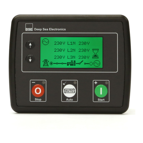
For further details of module configuration, refer to DSE Publication: 057-172 DSE45xx Configuration Software Manual. Inst. Instrumentation Unit Alarm Icon Icon Active Instrumentation Unit Config Mode FPE / Icon Auto Instrumentation Unit Load Switching Icons Example of DSE4510 Home Page Display Example of DSE4520 Home Page Display…
-
Page 40: Instrumentation Icons
Generator voltage and frequency instrumentation screen Mains voltage and frequency instrumentation screen (DSE4520 only) Generator current instrumentation screen Mains current instrumentation screen (DSE4520 only when CT in load location) Load power instrumentation screen Engine speed instrumentation screen Hours run instrumentation screen…
-
Page 41: Active Configuration
Viewing The Instrument Pages 5.2.2 ACTIVE CONFIGURATION An icon is displayed in the Active Config section to indicate the active configuration within the currently selected within the controller. Icon Details Appears when the main configuration is selected. Appears when the alternative configuration is selected. 5.2.3 FRONT PANEL EDITOR (FPE) / AUTO RUN ICON NOTE: For further details about the Front Panel Editor, see the section entitled ‘Front Panel Editor’…
-
Page 42: Load Switching Icon
Appears when the generator is available and the generator breaker is closed. Appears when the mains supply is not available and the mains breaker is open. (DSE4520 Only) Appears when the mains supply is not available and the mains breaker is closed. (DSE4520 Only) Appears when the mains supply is available and the mains breaker is open.
-
Page 43: Alarm Icons (Protections)
Viewing The Instrument Pages 5.2.7 ALARM ICONS (PROTECTIONS) An icon is displayed in the Alarm Icon section to indicate the alarm that is current active on the controller. In the event of a warning alarm, the LCD only displays the Alarm Icon. In the event of an electrical trip or shutdown alarm, the module displays the Alarm Icon and the Stop/Reset Mode button LED begins to flash.
-
Page 44: Warning Alarm Icons
Viewing The Instrument Pages 5.2.7.1 WARNING ALARM ICONS Warnings are non-critical alarm conditions and do not affect the operation of the generator system, they serve to draw the operators attention to an undesirable condition. By default, warning alarms are self-resetting when the fault condition is removed. However enabling ‘all warnings are latched’…
-
Page 45: Electrical Trip Alarm Icons
Viewing The Instrument Pages 5.2.7.2 ELECTRICAL TRIP ALARM ICONS Electrical trips are latching and stop the Generator but in a controlled manner. On initiation of the electrical trip condition the module de-energises all the ‘Delayed Load Output’ and the ‘Close Gen Output’…
-
Page 46: Shutdown Alarm Icons
Viewing The Instrument Pages 5.2.7.3 SHUTDOWN ALARM ICONS Shutdown alarms are latching and immediately stop the Generator. On initiation of the shutdown condition the module de-energises all the ‘Delayed Load Output’ and the ‘Close Gen Output’ outputs to remove the load from the generator. Once this has occurred, the module shuts the generator set down immediately to prevent further damage.
-
Page 47
Viewing The Instrument Pages Icon Fault Description Generator Under The generator output frequency has fallen below the pre-set alarm Frequency setting after the Safety On timer has expired. Generator Over The generator output frequency has risen above the pre-set alarm Frequency setting. -
Page 48: Viewing The Instrument
) page after the configured setting of the LCD Scroll Timer. 5.3.1.1 NAVIGATION MENU ICONS Icon Description Generator and mains voltage instrumentation (DSE4520 only) Generator instrumentation Mains instrumentation (DSE4520 only) Current and load instrumentation (Not available in on the DSE45xx-01 variant)
-
Page 49: General Navigation
Viewing The Instrument Pages 5.3.2 GENERAL NAVIGATION It is possible to scroll through the display to view different pages of information by repeatedly operating the (up) or (down) naviagation buttons. If you want to view one of the instrument pages towards the end of the list, it may be quicker to scroll up through the pages rather than down!
-
Page 50: Home
Mains Generator Voltage Voltage Generator Voltage (ph-N / ph-ph) • Mains Voltage (ph-N / ph-ph) (DSE4520 only) • 5.3.4 GENERATOR These pages contain electrical values of the generator, measured or derived from the module’s voltage inputs. Generator Voltage (ph-N) •…
-
Page 51: Mains (Dse4520 Only)
These pages contain electrical values of the load, measured or derived from the module’s voltage and current inputs. The power values displayed depend on which supply is on load. Generator Current (A) * • Mains Current (A) (DSE4520 only)* • Load ph-N (kW) * •…
-
Page 52: Engine
Viewing The Instrument Pages 5.3.7 ENGINE These pages contain instrumentation gathered about the engine measured or derived from the module’s inputs, some of which may be obtained from the engine ECU. 1500 Engine Speed • Engine Run Time • Engine Battery Volts •…
-
Page 53: Engine Dtc (Ecu Alarms)
Viewing The Instrument Pages 5.3.9 ENGINE DTC (ECU ALARMS) If the DSE module is connected to an ECU, This page contains active Diagnostic Trouble Codes (DTC) only if the engine ECU generating a fault code. These are alarm conditions are detected by the engine ECU and displayed by the DSE controller.
-
Page 54
Viewing The Instrument Pages Icon Fault DTC Description The engine ECU has detected a fault not recognised by the DSE Check Engine Fault module, contact engine manufacturer for support. The engine ECU has detected that the engine oil pressure has Low Oil Pressure fallen below its configured low oil pressure alarm level. -
Page 55: Event Log
Viewing The Instrument Pages 5.3.10 EVENT LOG This module’s event log contains a list of the last 15 record electrical trip or shutdown events and the engine hours at which they occurred. Once the log is full, any subsequent electrical trip or shutdown alarms overwrites the oldest entry in the log.
-
Page 56: Operation
Operation 6 OPERATION NOTE: The following descriptions detail the sequences followed by a module containing the standard ‘factory configuration’. Always refer to your configuration source for the exact sequences and timers observed by any particular module in the field. 6.1 QUICKSTART GUIDE This section provides a quick start guide to the module’s operation.
-
Page 57: Stopping The Engine
Operation 6.1.2 STOPPING THE ENGINE Select Stop/Reset mode. The generator is stopped. NOTE: For further details, see the section entitled ‘OPERATION’ elsewhere in this manual.
-
Page 58: Stop/Reset Mode
Operation 6.2 STOP/RESET MODE NOTE: If a digital input configured to panel lock is active, changing module modes will not be possible. Viewing the instruments and event logs is NOT affected by panel lock. Stop/Reset Mode is activated by pressing the Stop/Reset Mode button.
-
Page 59: Automatic Mode
Operation 6.3 AUTOMATIC MODE NOTE: If a digital input configured to external panel lock is active, changing module modes is not possible. Viewing the instruments and event logs is NOT affected by panel lock. Auto Mode is activated by pressing the Auto Mode button.
-
Page 60: Stopping Sequence
Operation 6.3.4 STOPPING SEQUENCE The return delay timer operates to ensure that the starting request has been permanently removed and isn’t just a short term removal. Should another start request be made during the cooling down period, the set returns on load. If there are no starting requests at the end of the return delay timer, the load is removed from the generator to the mains supply and the cooling timer is initiated.
-
Page 61: Manual/Start Mode
Operation 6.4 MANUAL/START MODE NOTE: If a digital input configured to panel lock is active, changing module modes is not be possible. Viewing the instruments and event logs is NOT affected by panel lock. 6.4.1 WAITING IN MANUAL MODE To begin the starting sequence, press the Manual/Start Mode button.
-
Page 62: Engine Running
Operation 6.4.3 ENGINE RUNNING Once the engine is running and all starting timers have expired, the animated Engine Running icon is displayed In manual mode, the load is not transferred to the generator unless a ‘loading request’ is made. A loading request can come from a number of sources. Activation of an auxiliary input that has been configured to Remote Start On Load or Auxiliary •…
-
Page 63: Maintenance Alarm
Operation — Maintenance Alarm 6.5 MAINTENANCE ALARM Depending upon module configuration one or more levels of engine maintenance alarm may occur based upon a configurable schedule. Example 1 Screen capture from DSE Configuration Suite Software showing the configuration of the Maintenance Alarm for Oil, Air and Fuel.
-
Page 64: Scheduler
Operation — Scheduler 6.6 SCHEDULER The controller contains an inbuilt exercise run scheduler, capable of automatically starting and stopping the set. Up to 8 scheduled start/stop sequences can be configured to repeat on a 7-day or 28-day cycle. Scheduled runs may be on load or off load depending upon module configuration. Example Screen capture from DSE Configuration Suite Software showing…
-
Page 65: Front Panel Configuration
Front Panel Configuration 7 FRONT PANEL CONFIGURATION This configuration mode allows the operator to fully configure the module through its display without the use of the DSE Configuration Suite PC Software. Use the module’s facia buttons to traverse the menu and make value changes to the parameters: Next Section (101→201→301) Previous Section…
-
Page 66: Accessing The Front Panel Configuration Editor
Front Panel Configuration 7.1 ACCESSING THE FRONT PANEL CONFIGURATION EDITOR Press the (-) and ( )buttons together to enter the editor mode. • Press the navigation buttons to cycle through the front panel editor to select the required • page in the configuration tables. Press the (+) to select the next parameter or (-) to select the previous parameter within the…
-
Page 67: Adjustable Parameters
Functionality in all DSE4510 & DSE4520 variants Functionality in all DSE4520 variants Functionality in DSE4510 & DSE4520 current sensing variants only Functionality in DSE4510 & DSE4520 RT & RTH variants only Configuration Parameters – Module (Page 1) Contrast 0 (%)
-
Page 68: Input Settings
Front Panel Configuration 7.2.3 INPUT SETTINGS Configuration Parameters – Inputs (Page 3) Digital Input A Source 0 (Input Source) Digital Input A Polarity 0 (Polarity) Digital Input A Action (If Source = User Config) 0 (Action) Digital Input A Arming (If Source = User Config) 0 (Arming) Digital Input A Activation Delay (If Source = User Config) Digital Input B Source…
-
Page 69: Output Settings
Functionality in all DSE4510 & DSE4520 variants Functionality in all DSE4520 variants Functionality in DSE4510 & DSE4520 current sensing variants only Functionality in DSE4510 & DSE4520 RT & RTH variants only Configuration Parameters – Outputs (Page 4) Digital Output A Source…
-
Page 70: Generator Settings
Functionality in all DSE4510 & DSE4520 variants Functionality in all DSE4520 variants Functionality in DSE4510 & DSE4520 current sensing variants only Functionality in DSE4510 & DSE4520 RT & RTH variants only Configuration Parameters – Generator (Page 6) Alternator Fitted On (1), Off (0)
-
Page 71: Mains Settings
Functionality in all DSE4510 & DSE4520 variants Functionality in all DSE4520 variants Functionality in DSE4510 & DSE4520 current sensing variants only Functionality in DSE4510 & DSE4520 RT & RTH variants only Configuration Parameters – Mains (Page 7) AC System 0 (AC System)
-
Page 72: Engine Settings
Front Panel Configuration 7.2.8 ENGINE SETTINGS Configuration Parameters – Engine (Page
 Start Attempts Over Speed Overshoot Over Speed Delay Gas Choke Timer (Gas Engine Only) Gas On Delay (Gas Engine Only) Gas Ignition Off Delay (Gas Engine Only) Crank Disconnect On Oil Pressure Enable On (1), Off (0) Check Oil Pressure Prior To Starting On (1), Off (0)
 -
Page 73: Analogue Inputs Settings
Front Panel Configuration 7.2.9 ANALOGUE INPUTS SETTINGS Configuration Parameters – Analogue Input Settings (Page 9) Analogue Input A Senor Type 0 (Sensor Type) Analogue Input A Sensor Selection 0 (Pressure Sensor List) Low Oil Pressure Enable On (1), Off (0) Low Oil Pressure Trip 0 Bar Oil Pressure Sender Open Circuit…
-
Page 74: Scheduler Settings
Functionality in all DSE4510 & DSE4520 variants Functionality in all DSE4520 variants Functionality in DSE4510 & DSE4520 current sensing variants only Functionality in DSE4510 & DSE4520 RT & RTH variants only Configuration Parameters – Scheduler (Page 10) 1001 Enable Scheduler…
-
Page 75: Maintenance Alarm Settings
Front Panel Configuration 7.2.12 MAINTENANCE ALARM SETTINGS Configuration Parameters – Maintenance Alarms (Page 12) 1201 Oil Maintenance Alarm Enable On (1), Off (0) 1202 Oil Maintenance Alarm Action 0 (Action) 1203 Oil Maintenance Alarm Engine Hours 1204 Air Maintenance Alarm Enable On (1), Off (0) 1205 Air Maintenance Alarm Action…
-
Page 76
Functionality in all DSE4510 & DSE4520 variants Functionality in all DSE4520 variants Functionality in DSE4510 & DSE4520 current sensing variants only Functionality in DSE4510 & DSE4520 RT & RTH variants only Configuration Parameters – Alternate Configuration (Page 20) 2024 CT Primary… -
Page 77: Selectable Parameter Settings
7.3.1 INPUT SOURCES Functionality in all DSE4510 & DSE4520 variants Functionality in all DSE4520 variants Functionality in DSE4510 & DSE4520 current sensing variants only Functionality in DSE4510 & DSE4520 RT & RTH variants only INPUT SOURCES User Configured Alarm Mute…
-
Page 78: Output Sources
7.3.2 OUTPUT SOURCES Functionality in all DSE4510 & DSE4520 variants Functionality in all DSE4520 variants Functionality in DSE4510 & DSE4520 current sensing variants only Functionality in DSE4510 & DSE4520 RT & RTH variants only OUTPUT SOURCES Not Used Air Flap Relay…
-
Page 79
Functionality in all DSE4510 & DSE4520 variants Functionality in all DSE4520 variants Functionality in DSE4510 & DSE4520 current sensing variants only Functionality in DSE4510 & DSE4520 RT & RTH variants only OUTPUT SOURCES Oil Pressure Sender Open Circuit Open Gen Output… -
Page 80: Alarm Action
Front Panel Configuration 7.3.3 ALARM ACTION ALARM ACTION Index Action Electrical Trip Shutdown Warning 7.3.4 FLEXIBLE SENSOR ALARM ACTION FLEXIBLE SENSOR ALARM ACTION Index Action None Shutdown Electrical Trip 7.3.5 POWER UP MODE POWER UP MODE Index Mode Stop Manual Auto 7.3.6 SENSOR TYPE SENSOR TYPE…
-
Page 81: Digital Input Alarm Arming
Front Panel Configuration 7.3.8 DIGITAL INPUT ALARM ARMING DIGITAL INPUT ALARM ARMING Index Arming Always From Safety On From Starting Never 7.3.9 DIGITAL INPUT POLARITY DIGITAL INPUT POLARITY Index Polarity Close to Activate Open to Activate 7.3.10 DIGITAL OUTPUT POLARITY OUTPUT POLARITY Index Polarity…
-
Page 82: Pressure Sensor List
Front Panel Configuration 7.3.12 PRESSURE SENSOR LIST PRESSURE SENSOR LIST Index Type Not used Dig Closed for Alarm Dig Open for Alarm VDO 5 Bar VDO 10 Bar Datcon 5 Bar Datcon 10 Bar Datcon 7 Bar Murphy 7 Bar CMB812 Veglia User Defined…
-
Page 83: Commissioning
Commissioning 8 COMMISSIONING Before the system is started, it is recommended that the following checks are made:- The unit is adequately cooled and all the wiring to the module is of a standard and rating • compatible with the system. Check all mechanical parts are fitted correctly and that all electrical connections (including earths) are sound.
-
Page 84: Fault Finding
Commissioning — Fault Finding 9 FAULT FINDING 9.1 STARTING Symptom Possible Remedy Unit is inoperative Check the battery and wiring to the unit. Check the DC supply. Check the DC fuse. Read/Write configuration does not operate Unit shuts down Check DC supply voltage is not above 35 Volts or below 9 Volts Check the operating temperature is not above 70°C.
-
Page 85: Alarms
Commissioning — Fault Finding 9.3 ALARMS Symptom Possible Remedy Low oil Pressure fault Check engine oil pressure. Check oil pressure switch/sensor and operates after engine has wiring. Check configured polarity (if applicable) is correct (i.e. fired Normally Open or Normally Closed) or that sensor is compatible with the module and is correctly configured.
-
Page 86: Miscellaneous
Commissioning — Fault Finding 9.6 MISCELLANEOUS Symptom Possible Remedy Module appears to ‘revert’ to When editing a configuration using the PC software it is vital that the an earlier configuration configuration is first ‘read’ from the controller before editing it. This edited configuration must then be “written”…
-
Page 87: Maintenance, Spares, Repair And Servicing
4510-02, 4510-03 & 4510-04 100-400-47 4520-02, 4520-03 & 4520-04 100-400-46 10.1.2 INDIVIDUAL PLUGS Module Terminal Designation Plug Description Part No. DSE4520 Only 9 way 5.08mm 007-166 DSE4510 Only 7 way 5.08mm 007-155 10-20 11 way 5.08mm 007-451 21-24 4 way 10.16mm 007-003 DSE4520 Only 4 way 10.16mm…
-
Page 88: Warranty
Warranty 11 WARRANTY DSE provides limited warranty to the equipment purchaser at the point of sale. For full details of any applicable warranty, you are referred to your original equipment supplier (OEM). DISPOSAL 12.1 WEEE (WASTE ELECTRICAL AND ELECTRONIC EQUIPMENT) Directive 2002/96/EC If you use electrical and electronic equipment you must store, collect, treat, recycle and dispose of WEEE separately from your other waste.
-
Page 89
This Page is Intentionally Left Blank… -
Page 90
This Page is Intentionally Left Blank…
 Start Attempts Over Speed Overshoot Over Speed Delay Gas Choke Timer (Gas Engine Only) Gas On Delay (Gas Engine Only) Gas Ignition Off Delay (Gas Engine Only) Crank Disconnect On Oil Pressure Enable On (1), Off (0) Check Oil Pressure Prior To Starting On (1), Off (0)
 This manual is also suitable for:
Dse4510
 Contact DSE® Sales & Support

DSE UK
T: +44 (0) 1723 890099
E: sales@deepseaelectronics.com
E: support@deepseaelectronics.com

DSE USA
T: +1 (815) 316-8706
E: usasales@deepseaelectronics.com
E: support@deepseaelectronics.com

DSE DUBAI
T: +971 (0) 45 910819
E: uaesales@deepseaelectronics.com

DSE INDIA
T: +91 (0)20 68195900
E: support@deepseaelectronics.com
Highfield House, Hunmanby Industrial Estate,
Hunmanby, North Yorkshire YO14 0PH
England
Products
DSEGenset®
DSEControl® DSEPower®
DSEAts®
About Us
Videos
News
Case Studies
Careers
Support
Product Software
Product Downloads
Support FAQs
Genset Non-Standard/Obsolete
Control Non-Standard/Obsolete
ATS Non-Standard/Obsolete
Power Non-Standard/Obsolete
Purchasing Terms & Conditions
Contact
Technical Support
Sales Support
Distributors
CAREERS
Log In
|
Register
Case Studies
Contact
Technical Support
Sales Support
Distributors
CAREERS
Log In
|
Register
Case Studies
Newsletter
Subscribe to our newsletter
Please enter a valid email address.


WEEE TAKE BACK |
Terms and Conditions / Privacy Policy
Modern Slavery Statement |
Code of
Conduct |
ISO9001: 2015 |
ISO14001: 2015
Registered in England & Wales 01319649 | VAT 3169 234 57
© Deep Sea Electronics 2023 |
Designed by Design Junkie

0,00 ₽
DSE4520 MKII Контроллер Deep Sea Модуль автоматического контроля сети
Доступно для предзаказа
Количество товара DSE4520 MKII Контроллер Deep Sea

-
Описание
-
Бренд
ИНСТРУКЦИЯ Deep Sea DSE4520 MK2
DSE4520-MKII-Data-Sheet
DSE4520 MK2 Контроллер Deep Sea – это компактный модуль автоматического контроля отказов сети (общего назначения), разработанный для обеспечения выдающегося набора функций в компактном корпусе.
ОСНОВНЫЕ ХАРАКТЕРИСТИКИ И ПРЕИМУЩЕСТВА
- Настраивается для использования в качестве модуля управления AMF или автозапуском. Обеспечивает исключительную гибкость. Заказчикам требуется только одна деталь для нескольких применений.
- Датчик скорости CAN и генератора переменного тока. Обеспечивает полную гибкость мониторинга.
- Самый большой дисплей с подсветкой в своем классе. Обеспечивает четкие и легко читаемые информационные страницы.
- Опция отображения с подогревом. Гарантирует, что дисплей продолжает работать в экстремально холодных погодных условиях.
- Резервные копии часов реального времени. Гарантирует, что данные не будут потеряны при отключении модуля от источника питания.
- Полностью настраивается с помощью программного обеспечения DSE Configuration Suite для ПК Обеспечивает полную удобную для пользователя конфигурацию и простое в использовании управление и мониторинг системы высокого уровня.
- Режим энергосбережения. Минимизирует разряд батареи, когда система не используется.
- 3-фазный генератор и датчик сети (общего назначения). Обеспечивает точное распознавание генератора и сети (общего назначения).
- Совместимость с номинальной системой ph-ph 600 В. Обеспечивает глобальную гибкость.
- Мониторинг мощности генератора и нагрузки (кВт, кВ A, кВ Ar, pf). Обеспечивает четкую и точную информацию об измерении мощности.
- Мониторинг накопленной мощности (кВт ч, кВА ч, кВАр ч). Обеспечивает точную индикацию количества энергии, вырабатываемой генератором.
- Защита генератора от перегрузки (кВт). Обеспечивает защиту двигателя от перегрузки.
- Мониторинг и защита тока генератора / нагрузки. Защищает генератор от перегрузки.
- Выходы подачи топлива и запуска (настраиваются на CAN). Предоставляет несколько вариантов установки.
- Выход 5 В. Для устройств подачи питания доступен один цифровой выход.
- Текстовый режим. Пользователи могут настроить модуль для отображения текста вместо стандартного отображения на основе значков.
- Совместим с широким спектром отправителей.
- Подходит для широкого диапазона отправителей и температур.
- Настраиваемые выходы подачи топлива и коленчатого вала. Обеспечивает повышенную гибкость для различных применений.
- Улучшено техническое обслуживание двигателя за счет температуры охлаждающей жидкости. Были внесены усовершенствования в температуру охлаждающей жидкости двигателя, чтобы включить предварительный сигнал тревоги для расширенного предупреждения.
Купить DSE4520 MKII Контроллер Deep Sea с доставкой по России. С услугой доставки и установки на ваше оборудование по всей территории России.
Бренд
Deep Sea Electronics
Компания Deep Sea Electronics является одним из ведущих мировых производителей контроллеров генераторов, контроллеров автоматического переключения, зарядных устройств для аккумуляторов и контроллеров транспортных средств и внедорожников. Продукция продается в 150 странах напрямую из головного офиса в Великобритании и через обширную дистрибьюторскую сеть.
DSE 4520 MK2

DSE 4520 MK2
Контроллер ДГУ DSE 4520 MK2 — предназначен для управления одной генераторной установкой.
Действует специальная оптовая цена при заказе от 10 шт.
- Описание
- Дополнительная информация
DSE 4520 MK2 — это компактный модуль управления отказом сети (AMF), разработанный для обеспечения широкого спектра функций. Отличается компактным корпусом.
КЛЮЧЕВЫЕ ОСОБЕННОСТИ
• Автозапуск и режим AMF в одном модуле (только DSE4520 MKII)
• Поддержка J1939-75 и CAN-сигнализации
• Контроль скорости оборотов двигателя по частоте генератора или по CAN — линии
• Самый большой дисплей с подсветкой в сравнении с размером корпуса
• Подогрев дисплея
• Часы реального времени обеспечивают точное ведение журнала событий
• Полностью настраивается через панель контроллера или ПК с помощью USB-кабеля
• Эффективный режим энергосбережения
• Контроль генератора по трем фазам, напряжение и ток
• Контроль сети по трем фазам, напряжение (только DSE4520 MKII)
• Контроль напряжения до 600 Вольт
• Контроль мощности генератора / нагрузки (кВт, кВA, кВAr, pf)
• Контроль выработанной мощности (кВт/ч, кВА/h, кВAr/h)
• Защита от перегрузки генератора (кВт)
• Контроль и защита тока генератора / нагрузки
• Управление стартером и топливным соленойдом (настраиваются даже при использовании CAN)
• 4 настраиваемых выхода постоянного тока
• 3 настраиваемых аналоговых / цифровых входа
• 4 настраиваемых цифровых входа
• Настраиваемые поэтапные выходные нагрузки
• Защита двигателя
• Счетчик моточасов
• Управление подогревом двигателя
• Управление холостым ходом двигателя для запуска и остановки
• 4- х строчный дисплей для вывода информации
• Контроль напряжения АКБ
• Работа контроллера при минимальном напряжении АКБ
• Конфигурируемый вход дистанционного пуска
• 1 альтернативная конфигурация
• Предупреждение, отключение нагрузки или останов двигателя при аварийной ситуации
• Индикация тревоги на экране контроллера
• Журнал событий на 50 ячеек
• Конфигурирование цифрового входа на датчик наличия воды в топливе
• Конфигурирование цифрового входа на сигнал тревоги
• Периодическое обращение к ECU (электронному блоку двигателя) для сбора информации при остановленном двигателе
• Режим энергосбережения, отключение подсветки
• Регулируемый таймер аварийной сигнализации
• Защита от перегрузки
• Выбор сисиемы переменного тока, сеть / генератор
• Таймер выхода для внешнего звукового сигнала
ОСНОВНЫЕ ПРЕИМУЩЕСТВА
• Лучшее соотношение размеров и характеристик
• Автоматическое переключение между сетью и генератором (только DSE4520 MKII)
• Счетчик моточасов обеспечивает контроль за периодичностью технического обслуживания двигателя
• Удобная настройка
• Одновременное отображение на экране нескольких параметров ДГУ
• Возможность гибкой настройки контроллера для обеспечения выполнения нестандартных задач
• Для настройки использует программное обеспечение DSE Configuration Suite
• Совместимость с большим количеством CAN-двигателей, включая Tier 4
• Лицензионное программное обеспечение для ПК. ПО предоставляется бесплатно
• Класс защиты IP65 (с дополнительной прокладкой) обеспечивает повышенную устойчивость к проникновению воды. Только с лицевой стороны.
Скачать программное обеспечение для настройки контроллера DSE4520 MK2, а так же просмотреть всю доступную по нему информацию, Вы можете на официальном сайте завода-изготовителя.
Дополнительная информация
| Вес | 0.26 kg |
|---|---|
| Габариты | 140 x 113 x 43 mm |
Похожие товары
DSE4520 — простейший контроллер автоматического запуска DeepSea с возможностью ввода резерва (AMF). Имеет встроенный детектор фаз. Является аналогом контроллера DSSE4420, дополнительно снабженного токовыми трансформаторами.
Модуль DSE4520 – Контроллер автоматического ввода резерва (AMF), используется для работы одиночной станции. Возможности параллельной работы не имеет.
Контроллер имеет возможность подключения датчика Pick-up или соединения с двигателем по CAN-шине.
Контроллер может производить запуск электростанции анализируя показатели внешней сети и отправлять сигнал на установленный АВР для переключения нагрузки.
Контроллер DSE4520 можно использовать совестно с АВРами различных производителей, которые будут иметь простейший функционал, и переключать нагрузку по сигналу от контроллера DSE.
Основные технические параметры, контроллера DSE4520:
- Автоматический запуск/останов
- Ручной запуск/останов
- Автоматическое подключение/отключение нагрузки
- Измерение параметров БГУ и сети
- Конфигурирование входных и выходных сигналов
- Экстренный останов по неисправности
- Программирование параметров с помощью ПО
Измерения
- Напряжение и частота сети
- Наработка двигателя (моточасы)
- Сила тока (А)
- Напряжение и частота электростанции
- Температура двигателя
- Напряжение стартерной батареи
- Давление масла в двигателе
- Скорость двигателя
Светодиодные индикаторы
- Основная сеть исправна
- Состояние контакторов генератора/сети
- Генератор готов к приему нагрузки
Аварийные сообщения и остановы
- Неудачный старт
- Низкое/высокое напряжение стартерной батареи
- Неудачный останов
- Неисправность зарядного генератора
- Низкое давление масла
- Разрыв цепи датчика скорости двигателя
- Низкий уровень топлива
- Отказ датчика скорости двигателя
- Высокая температура охлаждающей жидкости
- Аварийный сигнал от дополнительного датчика
- Низкая/Высокая скорость двигателя
- Неисправность контактора генератора
- Высокая/Низкая частота тока
- Нажатие кнопки аварийного останова
- Высокое/Низкое напряжение генератора
- Пропадание/Восстановление основной сет
Для покупки товара в нашем интернет-магазине выберите понравившийся товар и добавьте его в корзину. Далее перейдите в Корзину и нажмите на «Оформить заказ» или «Быстрый заказ».
Когда оформляете быстрый заказ, напишите ФИО, телефон и e-mail. Вам перезвонит менеджер и уточнит условия заказа. По результатам разговора вам придет подтверждение оформления товара на почту или через СМС. Теперь останется только ждать доставки и радоваться новой покупке.
Оформление заказа в стандартном режиме выглядит следующим образом. Заполняете полностью форму по последовательным этапам: адрес, способ доставки, оплаты, данные о себе. Советуем в комментарии к заказу написать информацию, которая поможет курьеру вас найти. Нажмите кнопку «Оформить заказ».