7OFH G (WH) RU/HA
7OFH G IX RU/HA
7OFHR G (AN)RU/HA
7OFHR G (OW)R
GOS 7 A RFH
GOS 7 I RFH
English
Operating Instructions
OVEN
Contents
Operating Instructions,1
W
Assistance,3
Description of the appliance,4
Description of the appliance,5
Installation,6
Start-up and use,9
Cooking modes,10
Precautions and tips,13
Maintenance and care,13
Ру
Руков
ДУХОВ
Содер
Руководств
Предупре
Сервисное об
Описание из
Описание из
У
Включение
Программы,19
Предост
Т
2
W
W
become hot during use. Care should be taken to
avoid
years of age shall be kept away unless continuously
supervised.
aged
reduced physical, sensory or mental capabilities or
lack of experience and knowledge if they have been
given supervision or instruction concerning use of the
appliance in a safe way and understand the hazards
involved. Children shall not play with the appliance.
Cleaning and user maintenance shall not be made
by children without supervision.
Do not use harsh abrasive cleaners or sharp metal
scrapers to clean the oven door glass since they can
scratch the surface, which may result in shattering of
the glass.
Never use steam cleaners or pressure cleaners on
the appliance.
W
of
of electric shock.
! When you place the rack inside, make sure that the
stop is directed upwards and in the back of the cavity
Предупреждения
ВНИМАНИЕ:
комплек
эксплуа
нагрева э Не разрешайт
де младше
бе контроля. Данное из може быть
испо
ограниченными
умств или опыта
знания
условии обучения
бе
соотв рисков. Не разрешайте
де
осуществ чистк и ух изде бе
контроля
Не использ абразивные вещ или
режущие ме скребки для чистки
стеклянной дверцы духовог шк так к
они поцарапать
привести
Никог не используйт паровые чистящие
агрег
для
ВНИМАНИЕ: был
выключено, перед заменой лампо в
изб
! При установке реше проверить, чтобы
фиксат
выемки.
3
Assistance
! Never use the services of an unauthorised technician.
Please have the following information to hand:
• The type
• The appliance
• The serial
The latter two pieces of information can be found on the data plate located
on the appliance.
Сервисное
!
При обращ
• Т
• Моде
• Номер т
Эти вы найдете расположенной
изде
4
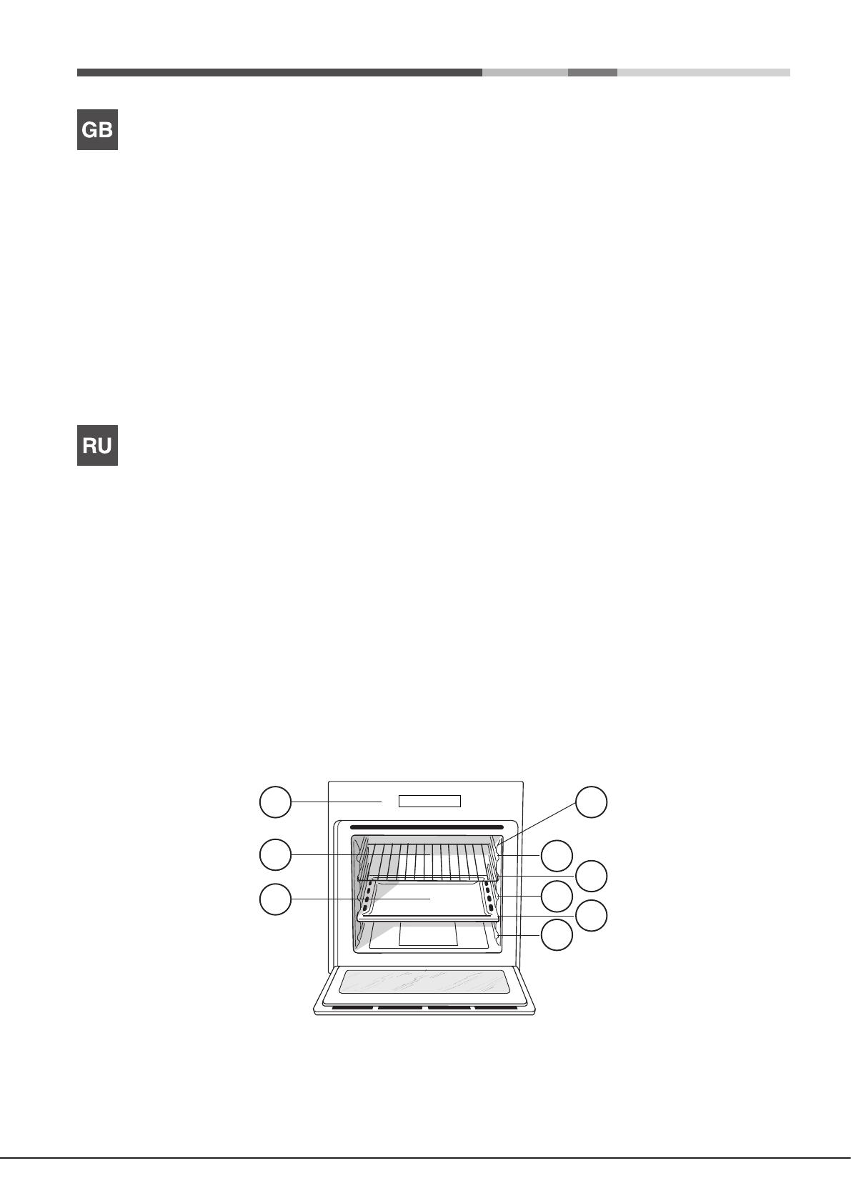
Description of the appliance
Overall view
1. POSITION 1
2. POSITION 2
3. POSITION 3
4. POSITION 4
5. POSITION 5
6. GUIDES for the sliding racks
7. DRIPPING P
8. GRILL
9. Control panel
Описание изделия
Общии вид
1. ПОЛОЖЕНИЕ
2. ПОЛОЖЕНИЕ
3. ПОЛОЖЕНИЕ
4. ПОЛОЖЕНИЕ
5. ПОЛОЖЕНИЕ
6. ВЫДВИЖНЫЕ НАПР у
7. ПРОТИВЕНЬ
8. РЕШЕТКА
9. Панель управления
8
9 6
2
5
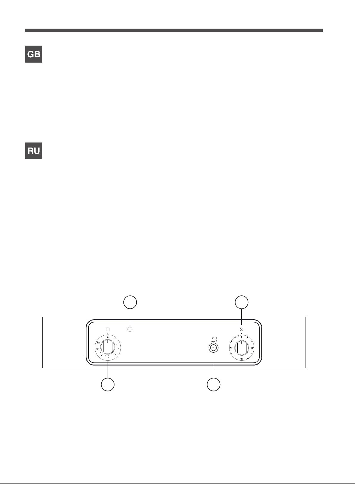
Description of the appliance
Control panel
1. OVEN/GRILL knob
2. GRILL indicator light
3. OVEN LIGHT button
4. TIMER knob
Описание изделия
Панель управ
1. Рукоятк
2. Индикатор
3. Кнопка ОСВЕЩЕНИЕ
4. Р
3
4
Min
Max
150
180
220
6
GB
Installation
! Please keep this instruction booklet in a safe place for future reference. If
the appliance is sold, given away or moved, please make sure the booklet is
also passed on to
contained within it.
! Please read this instruction manual carefully: it contains important in
concerning the safe operation, installation and maintenance of the appliance.
Positioning
! Do not let children play with the packaging material; it should be disposed
of in accordance local separated waste collection (see
Precautions and
! The appliance must be installed
with the instructions provided. Incorrect installation may damage property or
cause harm to people or animals.
!
in accordance with current National Regulations. The following requirements
must be observed:
• The
any combustion fumes. This may consist of a hood or an electric fan that
automatically starts each time the appliance is switched on.
In a chimney stack or branched flue.
(exclusively for cooking appliances)
Directly to
the Outside
• The must also allow proper air circulation, as air is needed for
combustion
3
/h
per kW of installed power
The air circulation system may take air directly
from the outside by means of a pipe with an
inner cross section of at least 100 cm
2
;
opening must not be vulnerable to any type
of blockages.
The system can also provide the air needed for
combustion indirectly
tted air circulation tubes as described
above. However
communal rooms, bedrooms or rooms that
may present
• Liquid
rooms
gas to escape in the event of a leak.
partially or completely full, must not be installed or stored in rooms or
storage
keep only the cylinder being used in the room, positioned so that it is not
subject to
etc. )
A
Examples of
ventilation holes
for comb
Enlarging the ventilation slot
between window and floor
Adjacent
Room
Room to be
V
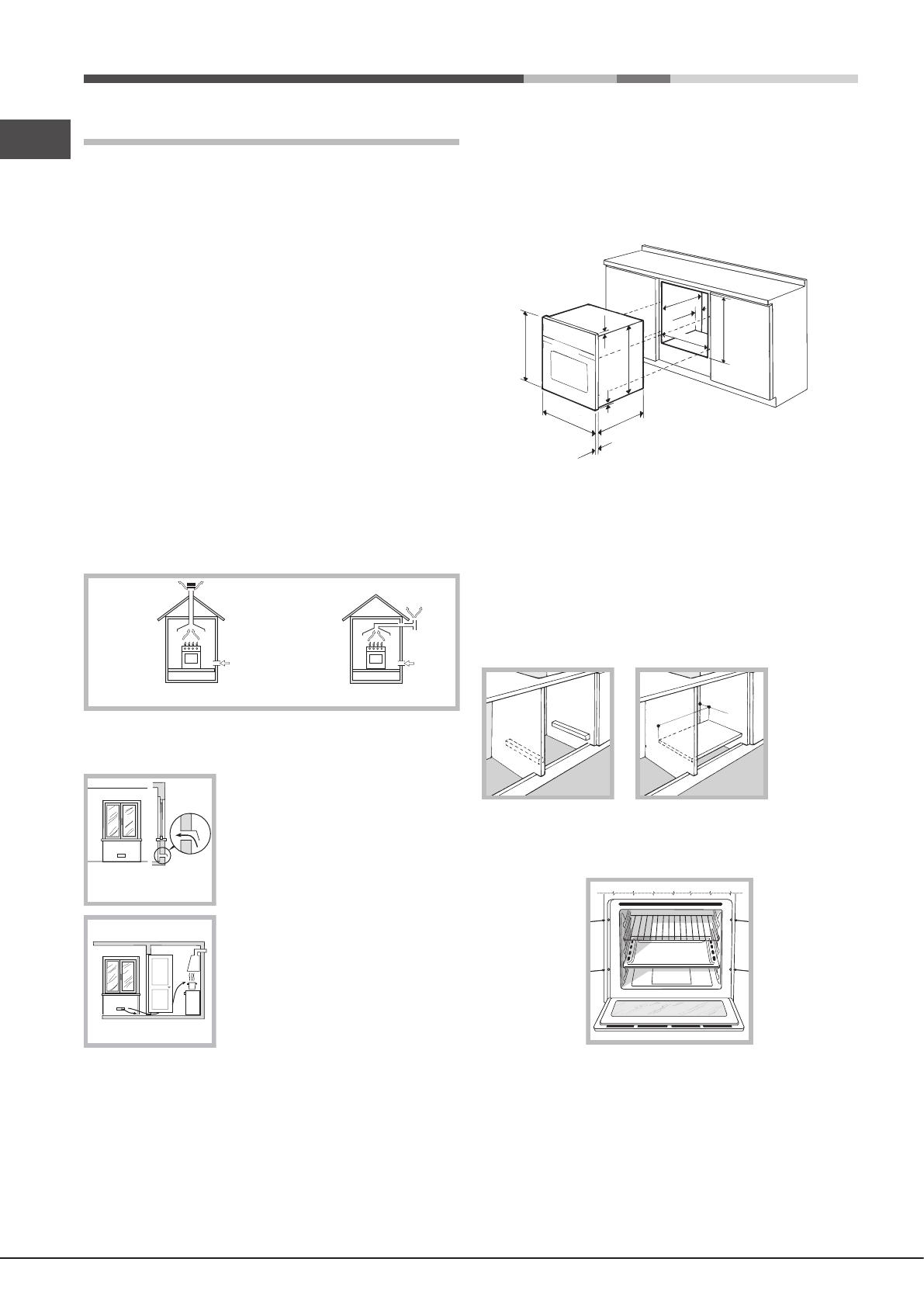
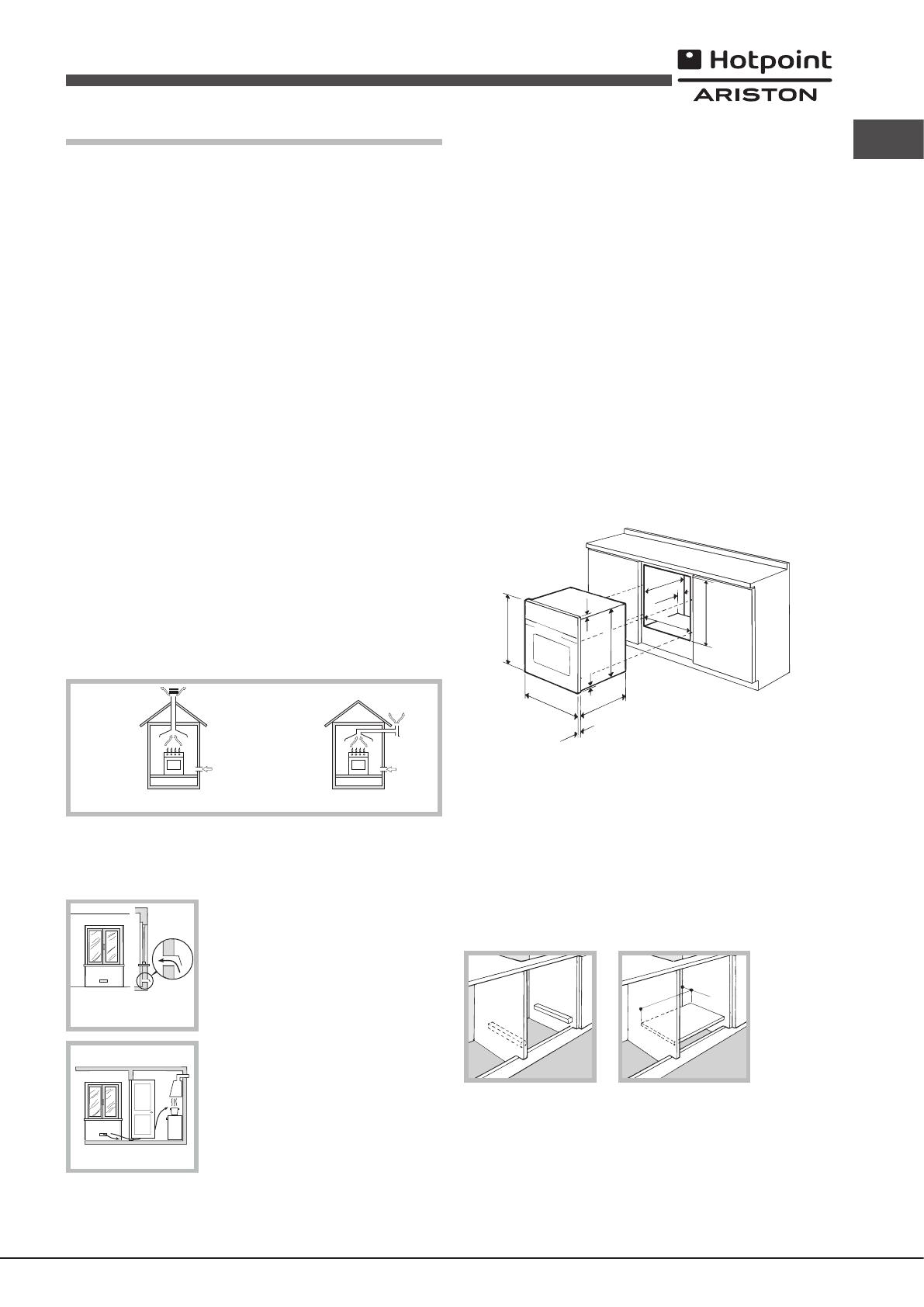
Built-in appliances
Use an appropriate cabinet to ensure that the appliance operates properly:
• The
• Cabinets
withstand temperatures
• Tunder the counter kitchen unit,
the cabinet must have the following dimensions:
595 mm.
595 mm.
25 mm.
545 mm.
5 mm.
567 mm.
23 mm.
575-585 mm.
45 mm.
560 mm.
547 mm. min.
!
been installed.
The indications for consumption given on the data plate have been calculated
for this type of installation.
V
T
removed. It is advisable to install the oven so that it rests on two strips of
wood,
mm (see
560 mm.
45 mm.
Centring and
Secure the appliance to the cabinet by opening the oven door and inserting
4 screws into the 4 holes on the outer frame.
!
removable without the aid of a tool.
Electrical connection
Ovens equipped with a three-pole power supply cable are designed to operate
with alternating current at the voltage and frequency indicated on the data
plate located
GB
7
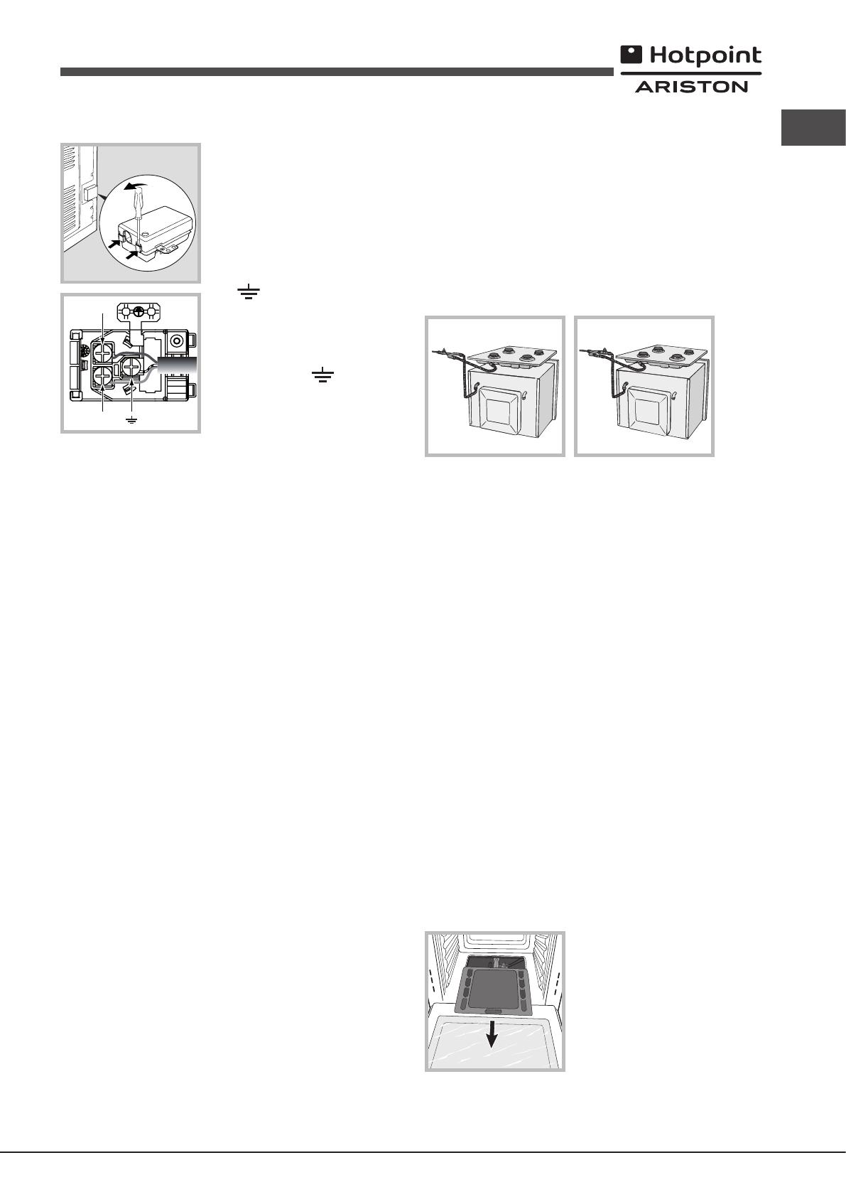
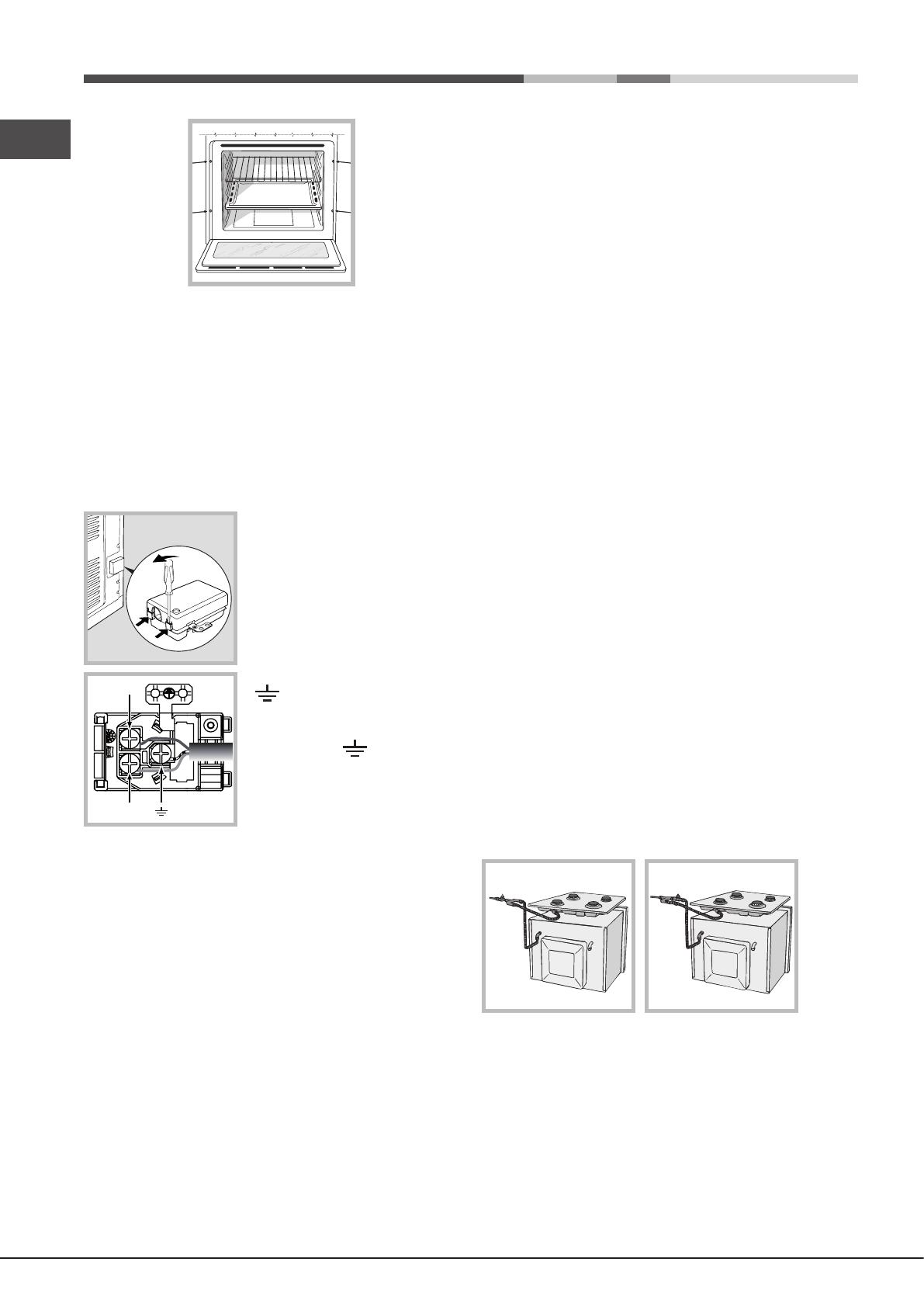
Fitting the power supply cable
1. Open the terminal board by inserting a
screwdriver into the side tabs of the cover
Use the screwdriver as a lever by pushing
it down
2. Install the power supply cable by
loosening the cable clamp screw
and the three wire contact screws
L-N- .
Connect the wires to the corresponding
terminals: the Blue wire to the terminal
marked
marked (L)
the terminal marked (see
3. Secure the cable by fastening the
clamp screw
4. Close the cover of the terminal board.
Connecting the supply cable to the mains
Install a standardised plug corresponding to the load indicated on the data
plate (see
The appliance must be directly connected to the mains using an omnipolar
switch with a minimum contact opening of 3 mm installed between the
appliance and the mains. The switch must be suitable for the charge
and
be interrupted
does not
(the back
!
performed and that it is fully compliant with safety regulations.
Before connecting the appliance to the power supply
• The appliance
• The
indicated on the data plate.
• The
• The
incompatible with the plug, ask an authorised technician to replace it. Do
not use extension cords or multiple sockets.
! Once the appliance has been installed, the power supply cable and
electrical socket must be easily accessible.
!
! The cable must be checked regularly and replaced by authorised technicians
only (see
! The manufacturer declines any liability should these safety measures
not be observed.
Gas connection
The appliance should be connected to the main gas supply or to a gas
cylinder in compliance with current National regulations. Before carrying
out the connection, make sure the cooker is compatible with the gas supply
you wish to use. If this is not the case, follow the instructions indicated in the
paragraph “Adapting to different types of gas.”
L
N
N
L
When using liquid gas from a cylinder
with current National regulations.
! Check that the pressure of the gas supply is consistent with the
indicated
the
energy consumption.
! Should you need to install a gas hob on top of a built-in gas oven, it is strictly
forbidden to connect the two or to use a single cut-off tap.
should be connected separately
order
NO
OK
Connection with a rigid pipe (copper or steel)
! Connection to the gas system must be carried out in
place any strain of any kind on the appliance.
There is an adjustable L -shaped
and
replaced
The
Connecting a
attachment
The gas supply pipe tting is a threaded
These pipes must be installed so that they are never longer than 2000 mm
when fully extended. Once connection has been carried out, make sure that
the
! Only use pipes and seals that comply with current National regulations.
Checking the tightness of the connection
! When
a soapy
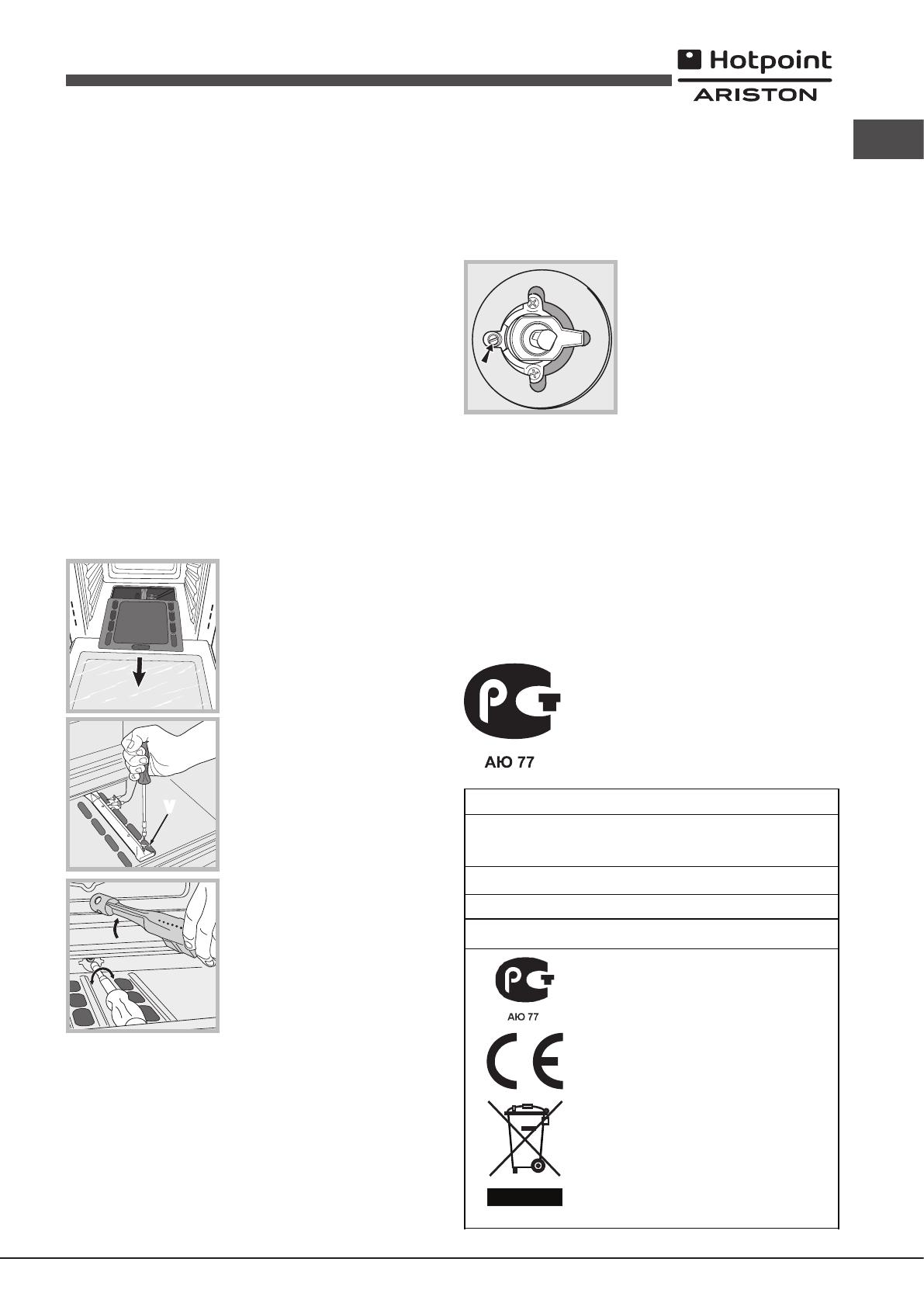
Adapting to different types of gas
In order to adapt the oven to a type of gas other than the type for which it was
manufactured (indicated
• Replacing the
1. Open the oven door fully
2. Slide out the bottom of the oven.
8
GB
V
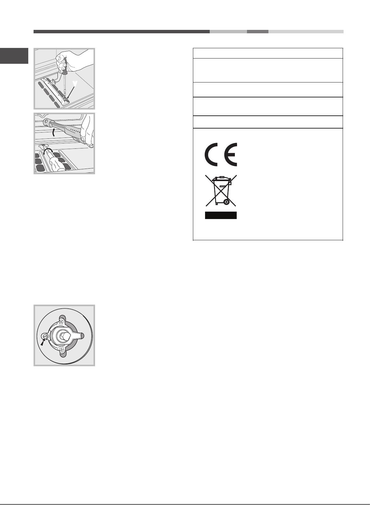
3. Unscrew the burner fastening screws.
4. Remove screw “V ” and then the oven
burner
5. Unscrew the oven burner nozzle using
the special socket spanner for the nozzles,
or better still a 7 mm socket spanner
replace it with a nozzle suited to the new
type of
6. Replace all the parts, following the steps described above in the reverse
order
! T
thermocouple pipes.
• Primary air
The burner was designed not to need any adjustments to the primary air
• Setting the
1. Turn
Min.
2. Remove the knob.
3. Remove the disk fastened to the control panel.
4. Adjust
is small
bottom).
5. Make sure the burner does not switch off
when you turn the knob from Max to Min
quickly
oven door quickly
! If the appliance is connected to liquid gas, the regulation screw must be
fastened as tightly as possible.
! rating sticker with one
indicating the new type of gas used. This sticker is available from any of our
Service Centres.
! If the gas pressure is dif
pressure regulator
National Regulations.
DATA PLATE
Dimensio ns
width 43 .1 cm
heig ht 31 .4 cm
depth .7 cm
Volume
59.1 l
Electri cal
connect ions
see data pl at e
Gas features
see data pl at e
EU Directive no 65/2014
supplementing Directive 2010/30/EU.
EU Regulation no 66/2014
implementing Directive 2009/125/EC.
Standard EN 15181
This appliance conforms to the
following European Economic
Community directives:
— 2006/95/EC of 12/12/06 (Low
Voltage) and subsequent
amendments;
— 2004/108/EC of 15/12/04
(Electromagnetic Compatibility)
and subsequent amendments;
— 93/68/EEC of 22/07/93 and
subsequent amendments.
— 2009/142/EC of 30/1
and subsequent amendments.
— 2012/19/EU and subsequent
amendments.
— 1275/2008 standby/off mode.
ENERGY LABEL
and
ECODESIGN
GB
9
Start-up and use
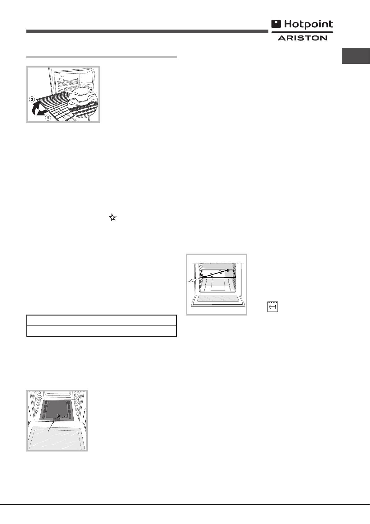
W The oven is provided
with a stop system to extract the
racks and prevent them from
coming out
As shown in the drawing, to extract
them completely
racks, holding them on the front
part, and
!
at its maximum temperature for at least half an hour
well ventilated before switching the oven off and opening the oven door
appliance may emit a slightly unpleasant odour caused by protective substances
used during the manufacturing process burning away
Starting the oven
This knob is used not only to select the different oven modes, but also to
choose the right cooking temperature for various foods from among the
temperatures
inclusive). The
knob. T
turn it anti-clockwise, setting it to position (keeping
The oven is equipped with a safety device.
gas to circulate until the safety thermocouple is heated by keeping the OVEN
knob pressed in for about 6 seconds.
!
more than 15 seconds. If the burner fails to light after 15 seconds, stop pressing
the OVEN knob, open the oven door and wait for at least one minute before
you try to light the burner again.
The cooking temperature is selected by matching the desired temperature with
the
is shown below:
Min• 150• 180• 220
ax
140145 160200 230240
The oven will automatically reach the temperature set, and the thermostat,
which is controlled by the knob, will keep the temperature constant.
Switching the oven on manually
In the event of a power failure, the oven burner can be lit manually:
1. Open the oven door
F
2. Hold a match or lighter near the burner
hole F
(see
setting it to the Max position.
The oven is equipped with a safety device.
gas to circulate until the safety thermocouple is heated by keeping the OVEN
knob pressed in for about 6 seconds.
3. Once the burner is lit, shut the oven door
!
to the off position, open the oven door and wait for at least
trying to light the burner again.
The GRILL knob
Y
temperature of the grill makes it possible to brown the surface of meats
and roasts while locking in the juices to keep them tender
highly recommended for dishes that require a high surface temperature:
beef steaks, veal,
Some examples of how the grill may be used are included in the “Practical
Cooking Advice”
! When using the grill, the oven door must be kept shut.
! Never put objects directly on the bottom of the oven — this could result in
damage to the enamel coating.
!
Cooling ventilation
In order to cool down the external temperature of the oven, some models
are tted
the oven door
! Once the cooking has been completed, the cooling fan remains
oven has
T
T operate the rotisserie function
diagram) proceed
1. Place the dripping pan in position 1.
2. Place the rotisserie support in position
3 and insert the spit in the hole provided
on the back panel of the oven.
3. Start the rotisserie using the knob to
select ;
Oven light
This is
How to use the timer
1. T
revolution.
2. T
on the knob with the indicator on the control panel.
3. The timer operates in minutes: when the selected time has elapsed, a
buzzer will sound.
! The timer does not switch the oven on or of
* Only available in certain models.
10
GB
Cooking modes
GRILL mode
The top heating element comes on. The extremely high and direct temperature
of the grill makes it possible to brown the surface of meats and roasts while
locking in the juices to keep them tender
for dishes that require a high surface temperature: beef steaks, veal, rib steak,
llets,
Practical cooking advice
! In the GRILL
cooking residues
GRILL
• Place
of the grill.
• We recommend
element is regulated by a thermostat and may not always be on.
PIZZA
• Use a
For
by extending
• If the pizza has a lot
cheese to the top of the pizza halfway through the cooking process.
GB
11
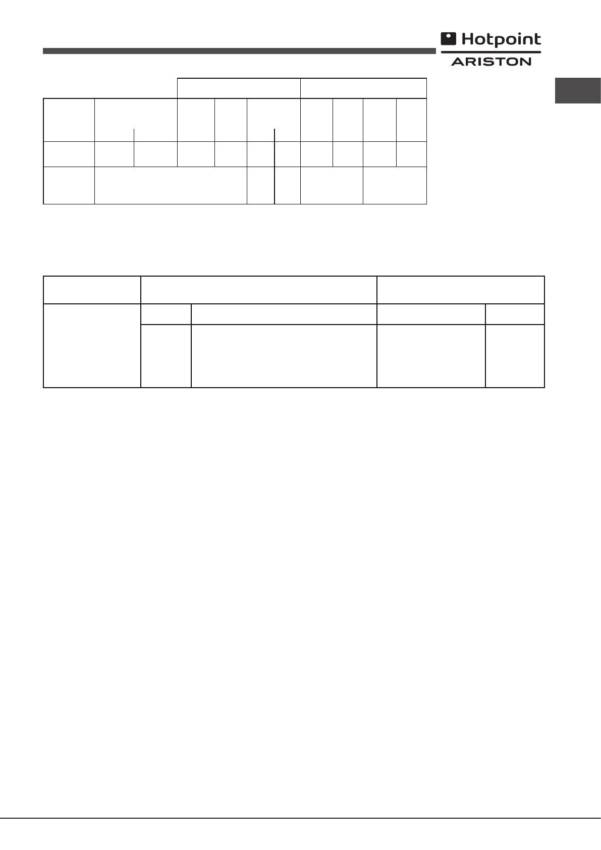
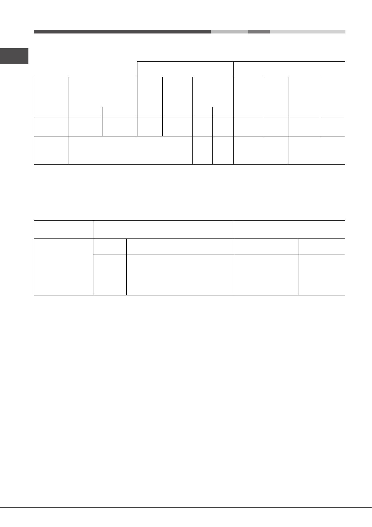
(1The val ues in g/h refe r to th e
flow
with liqu id gas (B ut Propane).
Gas Part Electric Pa rt
Category
Nominal Power
kW (1 )
Voltage fr equency
Power (W )
II2H3+2,60 ( 189 g/h — G3 0) (1 86 g/h — G 31) 220-240V
~
50/60Hz2250
7OFH G RU/HA
7OFH G IX RU/HA
7OFHRG RU/HA
GOS 7 A RFH
GOS 7 I RFH
Model
Thermal Powe r
kW
(p.c.s*)
2.60
Burner
1
Oven
Nominal Reduced
1.00
By/pass
1/100
(mm)
Nozzle
1/100
(mm))
Flow*
g/h
*** **
Nozzle
1/100
(mm)
Flow*
l/h
Nozzle
1/100
(mm)
Flow*
l/h
49 78 189 186 119 248 132 248
Supply
pressures
Nominal (mbar)
Minimum (mbar)
Maximum (mbar)
28-30
20
35
37
25
45
20
17
25
13
6.5
18
Liquid gas Natural gas
At 15°C and 1013,25 mbar — dry gas
Propane P. C.S. = 50.37 MJ/Kg
Butane P. C.S. = 49.47 MJ/Kg
Natural P. C.S. = 37.78 MJ/m³
12
GB
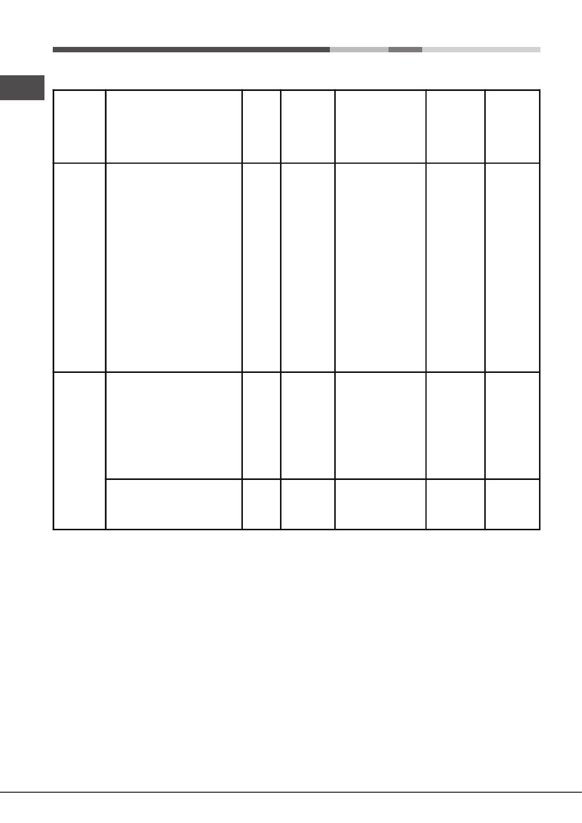
Selector
knob
setting
Food to be cooked Wei ght
(in kg)
Cooking
rack
position
from oven
bottom
Preheating time
(minutes)
Thermostat
knob
setting
Cooking
time
(minutes)
Oven
Lasagne
Cannelloni
Pasta
Veal
Chicken
Tu rkey roll
Duck
Rabbit
Pork loin
Leg of lamb
Mackerels
Dentex
Tr out ke d in fo il
Neapolitan-style pizza
Dry biscuits
Ta rt
Chocolate ke
Leav ened cakes
2,5
2,5
2,2
1,7
1,5
2,5
1,8
2,0
1,5
1,8
1,3
1,5
1,0
0,6
0,5
1,1
1,0
1,0
3
3
3
2
3
3
3
3
3
3
3
3
3
3
4
3
3
4
10
10
10
10
10
10
10
10
10
10
10
10
10
15
15
15
15
15
200
200
200
210
200
200
200
200
200
200
200
180
200
210
180
180
165
165
55-60
40-45
50-55
80-90
70-80
80-90
90-100
80-90
70-80
80-90
30-40
30-40
30-35
15-20
25-30
30-35
50-60
50-60
Grill
Soles and cuttlefis h
Squid aw n k ebabs
Cod filet
Grilled vegetables
Veal k
Chops
Hamburgers
Sausages
To asted sandwiches
1
1
1
1
1
1,5
1
1,7
n.° 4
4
4
4
4
4
4
4
4
4
5
3
3
—
5
5
3
5
3
—
—
—
—
—
—
—
—
—
6
4
10
8-10
20-25
20-25
10-15
20-25
2-3
With rotisserie
(where present)
Veal the spit
Chicken t he spit
Lamb on t he spit
1.0
1.5
1.0
—
—
—
—
—
—
—
—
—
80-90
80-90
80-90
! Cooking times appro xi ma te and ma y vary according to personal taste. When cooking using the grill, the
dripping p an mu st wa ys be the 1st ov en rack from t he bottom.
Cooking advice table
GB
13
Precautions and tips
!
international safety standards. The following warnings are provided for safety
reasons and must be read carefully
General safety
• This is a class 3 built-in appliance.
• Gas
operation. When installing the cooker
provided in the paragraph on “Positioning” the appliance.
• The
intended for commercial or industrial use.
• The
extremely dangerous to leave the appliance exposed to rain and storms.
• When or appliance, always handles
provided on the sides of the oven.
• Do
feet.
• The appliance must be used by adults only for the preparation of
food, in accordance with the instructions provided in this booklet.
Any other use of the appliance (e.g. for heating the room) constitutes
improper use and is dangerous. The manufacturer may not be held
responsible for any damage caused as a result of improper
and unreasonable use of the appliance.
• Do not touch the heating elements or certain parts of the oven door
when
Keep children well away from the appliance.
• Make
not come into contact with the hot parts of the oven.
• The ventilation
• Always grip
• Always
removing it.
• Do not
• Do
on accidentally
• Always ○ ” position when the appliance
is not in use.
• When the appliance, the mains
socket; do
• Do perform any cleaning or ma work without having
disconnected the appliance from the electricity mains.
• If the
to
Assistance).
• Do not
• Do not
• The should not be operated by people (including children)
with reduced physical, sensory or mental capacities, by inexperienced
individuals or by anyone who is not familiar with the product. These
individuals should, at the very least, be supervised by someone who
assumes responsibility for their safety or receive preliminary instructions
relating to the operation of the appliance.
• The
timer or separate remote-control system.
Disposal
• When
the packaging may be reused.
• The European Directive 2012/19/EU on W Electrical and
Electronic
appliances must not be disposed of in the normal unsorted municipal
waste stream. Old appliances must be collected separately in order
to optimise the recovery and recycling of the materials they contain
and reduce the impact on human health and the environment.
The crossed out “wheeled bin” symbol on the product reminds you of your
obligation, that when you dispose of the appliance it must be separately
collected.
Consumers should contact their local authority or retailer for information
concerning the correct disposal of their old appliance.
Respecting and conserving the environment
• Whenever possible, avoid pre-heating the oven and
Open the oven door as little as possible because heat is lost every time
it is opened. T
the oven 5 to 10 minutes before the end of your planned cooking time
and use the heat the oven continues to generate.
• Automatic programmes
• Keep gaskets
• If you have a
will make it easier to save money by moving operation to cheaper time
periods.
!
on the limitation of power consumption of the standby mode.
Maintenance and care
Switching the appliance off
Disconnect your appliance from the electricity supply before carrying out
any work on it.
Cleaning the appliance
• The
may be cleaned using a sponge that has been soaked in lukewarm water
and neutral soap. Use specialised products for the removal of stubborn
stains.
powders or corrosive substances.
• The
still lukewarm. Use hot water and detergent, then rinse well and dry with
a soft cloth. Do not use abrasive products.
• All accessories —
like everyday crockery
! Never use steam cleaners or pressure cleaners on the appliance.
Cleaning the oven door
Clean the glass part of the oven door using a sponge and a non-abrasive
cleaning product, then dry thoroughly with a soft cloth. Do not use rough
abrasive material or sharp metal scrapers as these could scratch the surface
and cause the glass to crack.
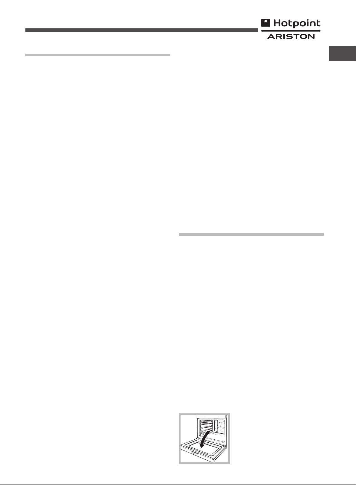
T
1. Open
14
GB
2. Lift up and turn the small levers located on
the two
3. Grip the door on the two external sides
and close it approximately half way
door
diagram).
T
Inspecting the seals
Check the door seals around the oven regularly
please
that the oven is not used until the seals have been replaced.
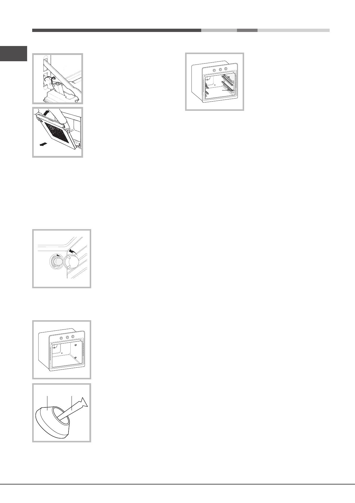
Replacing the light bulb
T
1. Remove the glass cover of the lamp-
holder
2. Remove the light bulb and replace it with
a similar one: W
3.
!
Sliding Rack Kit assembly*
T
1. Loosen the two screws A (see
diagram). the oven
cleaning panels, these will have to be
temporarily disassembled.
2. Replace the screws
and B + C )
3.TB and the
corresponding spacers C , tting
cleaning panels on again.
4. Secure the two joints D of the guide rail
in the holes provided on the oven walls
(see
rail are situated at the top, while the holes
for the right one are at the bottom.
5. C.
! Do not place the sliding racks in position 5.
* Only available in certain models.
15
RU
У
! Важно сохранить данное руково для его после
консуль
на новое
оставалось изде
мог и с
предупре
! Внимат инструкции: в них содержа важные
све
Распо
! Не разрешаите де играть с упаковочными мат
У быть уничто в соотве
с правилами раз сбора м (см. и
рекомендации).
! Монтаж
квалифицированными
може ста причинить ущерб
людям
! Данное
помещениях
деиствующих Нормативов. Необ с следующие
требования:
• В помещении
в атмосфер в виде вытяжног зонта или
электровентилят включающих к раз,
ког
B камин или в дымохо д с медным покрытием
(для ку хонных устpойств для приготовл ения пищи)
Нeпосредствeннo
в aтмосфepy
• В
доста воздух для горения. Расх
воз
3
/час
на кВ
Приток воздух може обеспе
непосредств снаружи здания
воз
100 см
2
и диаме исключающим
возмо
Или же воз може
осуществ
оснащенных
сообщающимся с улиц к описано
выше,
здания, не
спальни.
A
Пpимepы вeнтиляциoнных
отвepстий для притокa
вoздyхa для гоpeния
Cмeжное
помещение
Вентилируемо е
помещение
Увеличение зазо ра
между дверъю и полом
• Сжиженныи газ и сле
застаивае внизу По эт причине помещения, в к
установ баллоны с СНГ (сжиженным натуральным
должны
улиц
должны
они
и (подвалах, Следуе держать помещении
то
он
каминов
50°C.
Встроенный м
Для
кухонный э
• Панели
быть выпо
• Клей элементов, деревом,
должен
• Для под
или
размеры:
595 mm.
595 mm.
25 mm.
545 mm.
5 mm.
567 mm.
23 mm.
575-585 mm.
45 mm.
560 mm.
547 mm. min.
! После встраивания в кухонный э должна быть
исключена
Р
был замер
Вентиляция
Для
пане
шкаф на два деревянных бруска или на сплошное основание с
отв
560 mm.
45 mm.
Центровка и
Для
шкафа
периме
16
RU
! Все
чтобы их можно было снять то при помощи специального
инструмент
Э
Духовые шк
расчитаны на функциониров
и электропитания, паспортной с
данными (см.
Под
1.
при помощи отв выступы с
боков крышки: потяните откройт
крышку (см.
2. Порядок по сетев
кабеля: винт к
сальника и три
и
го
маркировку Синий
Же (см. схему).
3. Закрепите сетев в
специальном кабе
4.
Под
У
расчитанную
В
и се необх установить мног выключа с
минимальным между к мм, расчитанный
на данную нагрузку с
(выключа
должен
темпера
(например, задняя
! несет подключение
изде
Перед подключением изде к се электропитания проверь
следующ
• розе
норматив
• сетев розе должна быть рассчитана на максимальную
потре
характеристик;
L
N
N
L
• напряжение и часто тока се до с
электрическим
• се
изде В про случае замените или вилк не
использ
! должно установлено образом,
электропитания
!
! Регу
необ
(см. Т
! Фирм снимае с себя всякую отв в случае
несоб
Под
Подсое
осуществ в соотве с действую национальныи
норматив
соотве изде типу га к которому подсоединяе В
случае
“Настройка на ра
В с баллона использов
регулят
норматив
! функционирования,
энергии более слу
проверь значениям,
указанным в
! В уст г вместе с га
духовкой
использ
быть
каждое из них должно газовый
схемы).
NO
OK
Под
!
на из
На в имеется
с При
обяза упл прокладку (прилагающе
к Патрубок цилиндрическ
наружную ре
17
RU
Подсоединение
со спл
Патр по в имее цилиндрическую наружную
резьб
Подсое
чтобы
По
шланг не
! Испо и мет алюминиевые
резиновые
национальным норма
Проверка
!
патр
Настройка на
Для
который необх
следующие
• Порядок
1. Полностью о
2. Вынь
V
3. Oтвинтит
4. V ”-
образный
5.
при
для
полым мм и замените
форсунку
(смотре
6. место выполняя
выше операции
!
трубки
• Р
Г
регуляции
• Р
1. Поверните регулят
положении
2. Cнимите рукоятку
3. Cнимите диск,
4 П
вплоть
отв
5. проверить, чтобы горе не
гасла ре вращении
регулят из положения Max в
положение Min или при резком
открыв или закрывании дверцы
духовки.
!
завинчен до
! По завершении замените стар э с старыми
настройками
га Этик можно зак в наших Центрах Т
Обслуживания.
!
давления варьир необ установить питающ
га соотве регулятор давления (с
действующим
ПАСПОРТНАЯ ТАБЛИЧКА
Электропитание
См. таблицу характеристик
Характеристики газа
См. таблицу характеристик
Габаритные
размеры
ширина 43,1 см.
высота 31,4 см.
глубина 43,7 см.
Объем
59,1 л
Данное изделие соответствует
следующим Директивам
Европейского сообщества:
— 2006/95/CE от 12/12/06
(Низкое напряжение) и
последующим изменениям.
— 2004/108/CE от 15/12/04
(Электромагнитная совместимость)
и последующим изменениям.
— 93/68/CEE от 22/07/93 и
последующим изменениям.
— 2009/142/CE от 30/11/09 (Газ) с
последующими изменениями.
— 2012/19/UE и последующим
изменениям.
18
RU
Вклю
ВНИМАНИЕ! Духовой шк
укомплектован системой
б реше
позво вынимать их из
духовки
Для
доста поднять их, к
показано на их за
передний и потянуть
себ
! При первом шкафа рекомендуем
его с
закрытой
и к
вызван веществ, для предо
духовог
Вклю
При
режимы
140°C до 240°C), для б
Э внутри Для
зажигания
стре
духовки). как духовка оснащена устройством,
зажигания Д
примерно
защитной т
!
нажатым
не зажглась, отпу
подо
Выбор температуры осуществ с
нужного зна
полный
Min• 150• 180• 220
ax
140145 160200 230240
Духовк
поддержив неизменной при помощи устройства
(термоста
Зажигание духовки
В временного отключения можно включить
горе
1. Oткройт
F
2. П однесит спичку или кухонную
зажигалку к показано на рисунке,
нажмите упора и поверните
часовой стре рукоятку Д
вплоть
Т
горе
в
термопары.
3. После
!
ДУХОВКИ,
до пов
Рукоятка-рег
Ваша духовка оснащена электрическим грилем. Значите
темпера прямого гриля позв получить
образов
выхо соков и сохраняе продукт нежным и сочным внутри.
Использ функции гриль в особенности рекомендуе для
б которых
темпера
гам
В “Прак с пригот
некоторые
!
закрытой.
!
они могут
!
Охладительная в
Для температуры духовог шкафа
некоторые оснащаются
вентилятор струю
дверцей
!
до надле
Вертел*
Для включения верте (см. схему)
выполнит
1.
2.
уровень
отв в задней стенке духовог
шкафа;
3.
ПРОГР ;
Освещение
Освежение
* Имее
19
RU
Т
1. Прежде всго необ
по часовой
2.
время – минуты на рукоятке ТАЙМЕР
пане
3.
времени ра
!
Программы
Программа
Включае
прямог действия гриля получить образование
корочки
сохраняе
гриль в особенности для б пригот
которых
гов
б
Практические
!
для сбора
ГРИЛЬ
• У
реше
• Р выбра максимальную мощность духовки.
беспокойтесь, если верхний элемент не остае постоянно
включенным:
ПИЦЦА
• Использ
прилагающуюся
При использовании время выпечки что
затр
• В случае выпечки пиццы с обильной начинкой рекомендуе
положить
20
RU
Категория
Номинальная мощность
кВт (1)
Напряжение
частота
Мощность
(
Вт
)
II2H3+2,60 (1 89 g/h — G30) (186 g/h — G 31) 220-240V
~
50/60Hz 2250
7OFH G RU/HA
7OFH G IX RU/HA
7OFHRG RU/HA
GOS 7 A RFH
GOS 7 I RFH
Модель
Газовая часть
Электрическая част
(1Значения выр аженные в гр/час, относятся к характеристикам сжиженных газов (бутан пропан.
* При те мпературе 15°C и давл ении 1013,25 мб ар – сухой газ
** Пропан Теплотворная спосо бность = 50,37 МДж/кг
*** Бу тан Теплотворная спосо бность = 49,47 МДж/кг
Природный газ Теплотворная спосо бность = 37,78 МДж/м
3
НоминальнаяСокращенная
2.60
Глкa
Д
ухово
й
шкаф
1.00
*** **
49 78 189 186 119 248 132 248
28-30
20
35
37
25
45
20
17
25
13
6.5
18
Характеристики горел
Таица 1
Сжижаз Природный газ
Теплотворная
способность кВ
(p.c.s.*)
Байпас
1/100
(
мм
)
Форсунка
1/100
(
мм)
Расход
*
г/час
Форсунка
1/100
(
мм)
Расход
*
л/час
Форсунка
1/100
(
мм)
Расход
*
л/час
Давление
подачи
Номинальное (мб
Минимальное (мб
Максимальное (м