Приветствую! Представляю обзор лучшего (по моей имхе) DIY набора. Часы с календарем, будильником, датчиком температуры и светодиодной секундной стрелкой. Подробности, много фото и видео работы далее.
Итак, начнем.
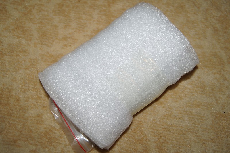
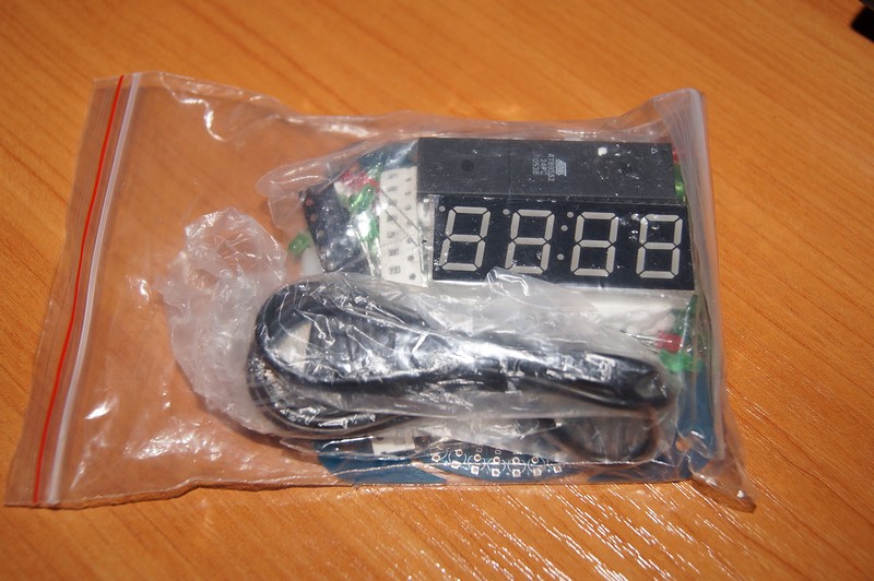
Пришел кит замотанный в мягкую транспортировочную пленку
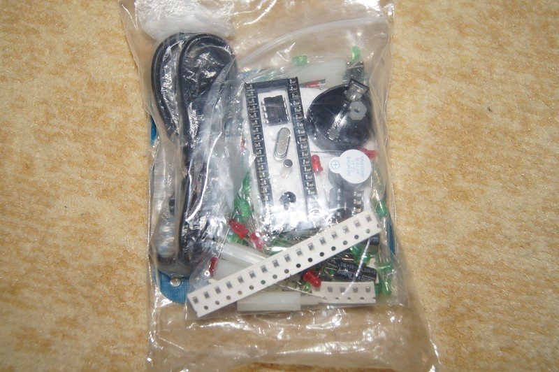
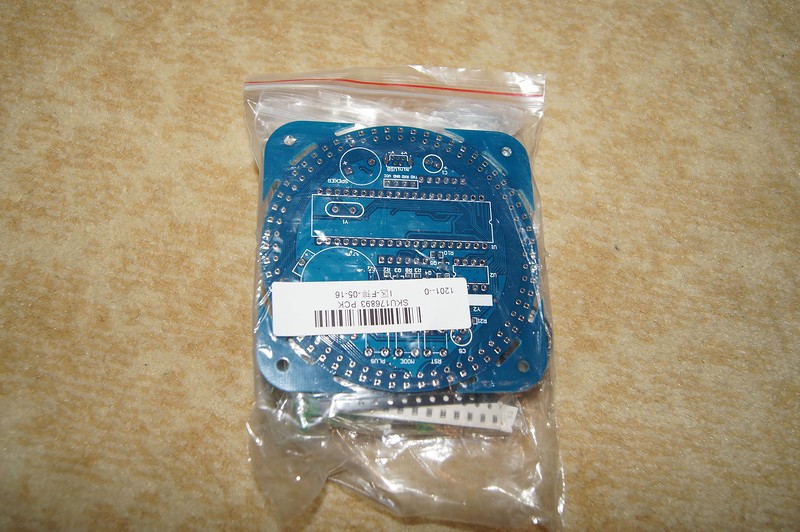
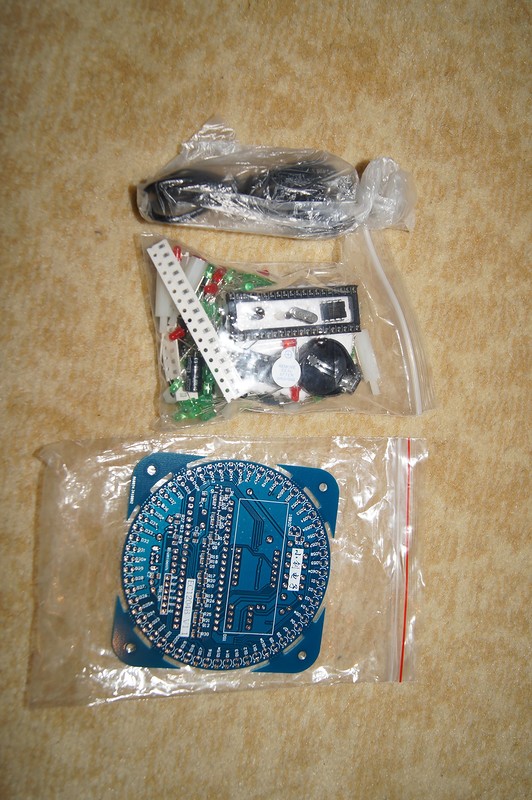
Все необходимое разложено по зип-лок пакетам
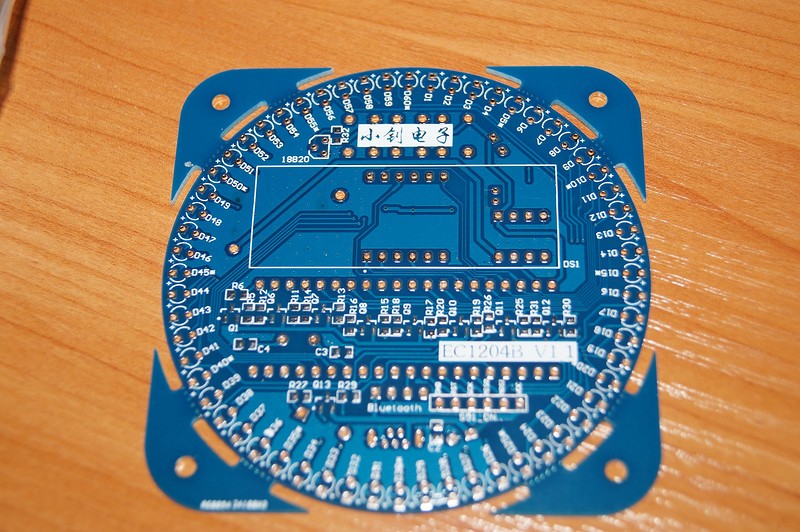
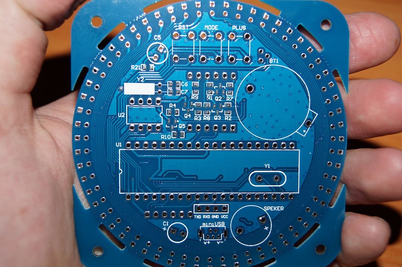
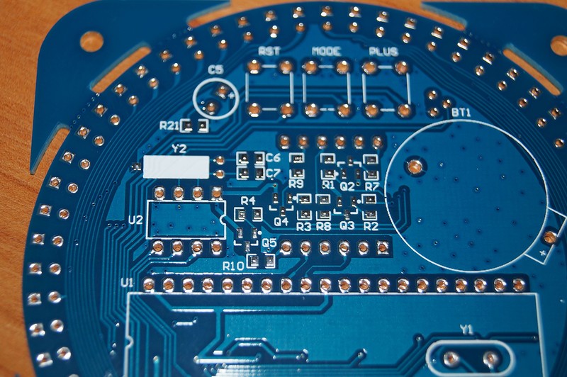
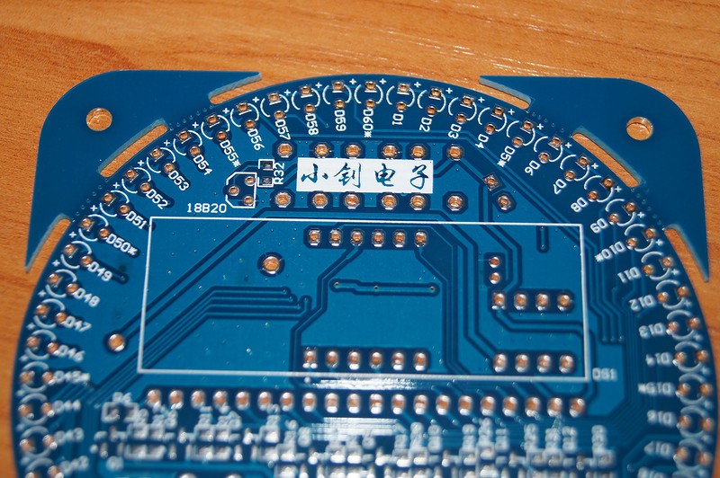
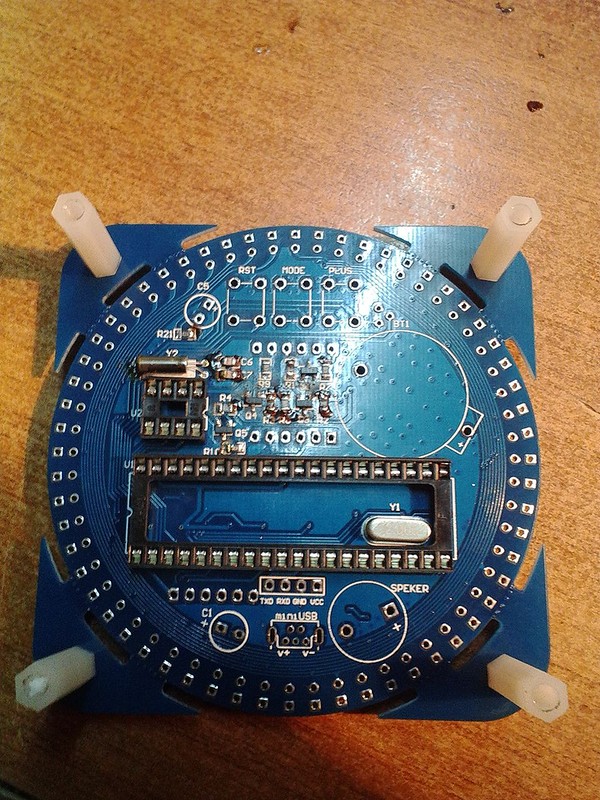
Плата отличного качества
Размер 81 mm x 81 mm x 1.6 mm
Уголки перфорированы, так что можно при желании их обломать если нужно внедрить часы например в круглый корпус.
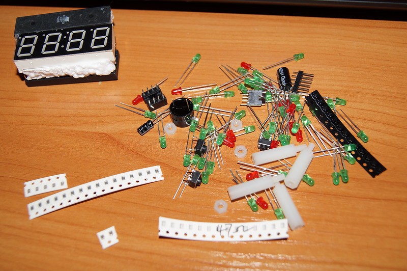
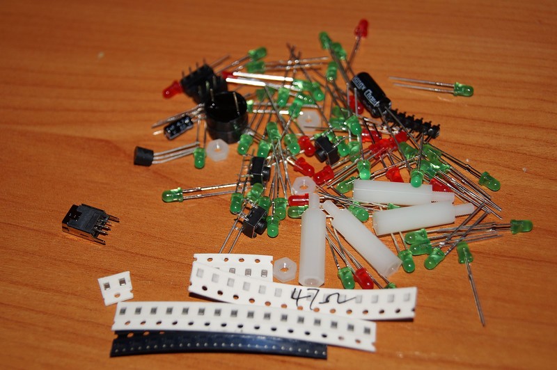
Высыпаем содержимое
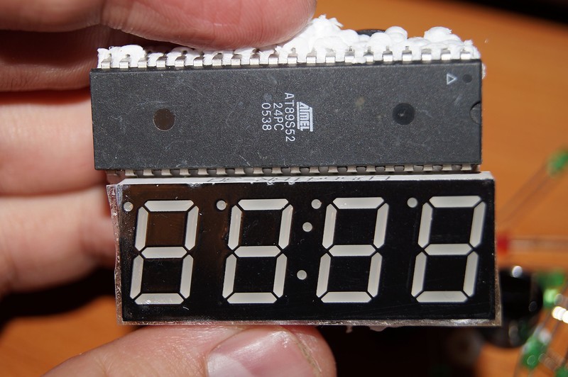
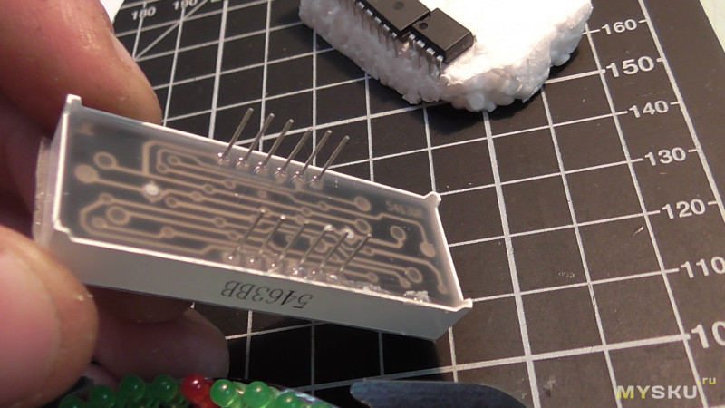
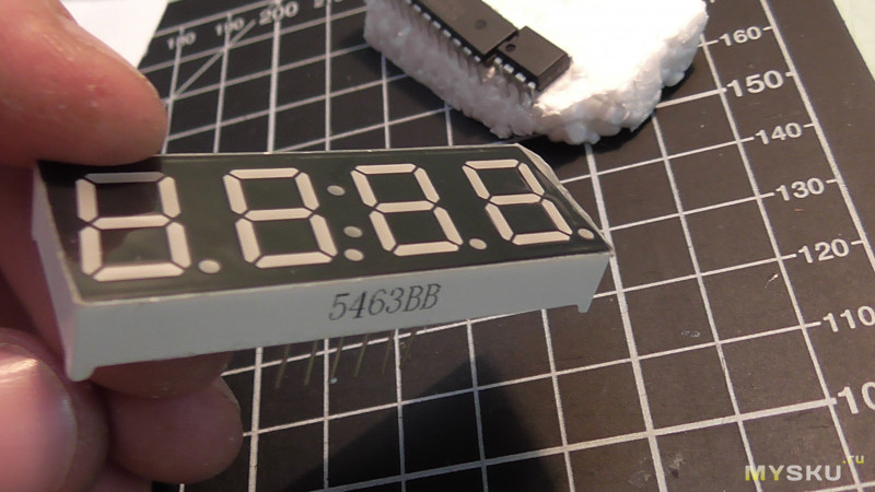
Индикатор с контроллером на пенопласте, дабы ноги были целыми.
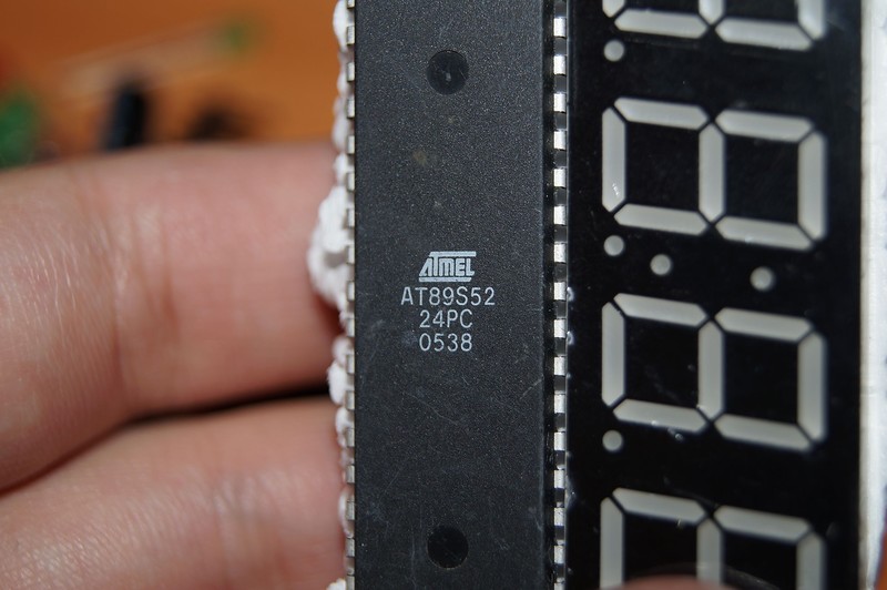
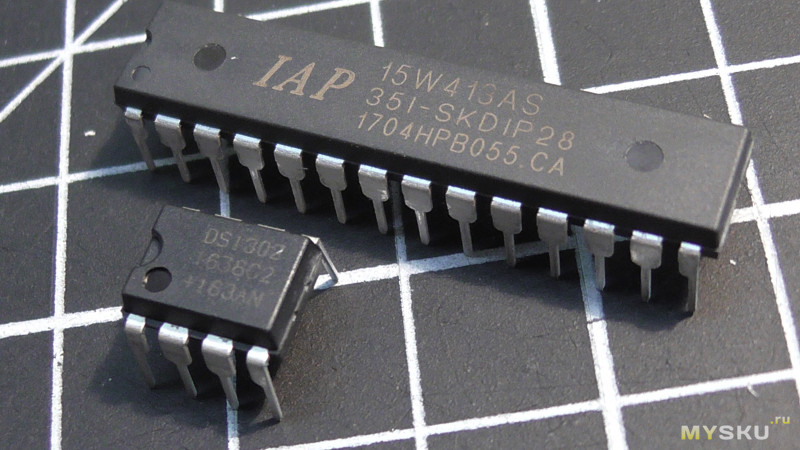
Контроллер уже с прошивкой
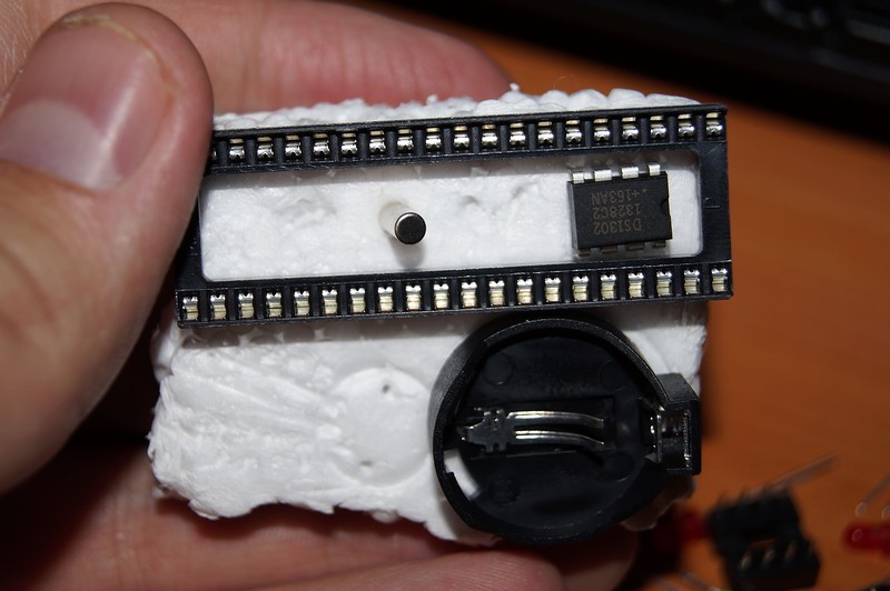
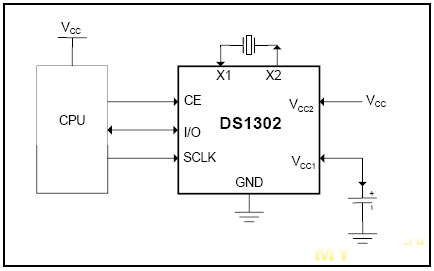
Микросхема реального времени DS1302
Все SMD в лентах
Хороший датчик температуры DS18B20
Сборка
Снимал на телефон, так что извиняйте.
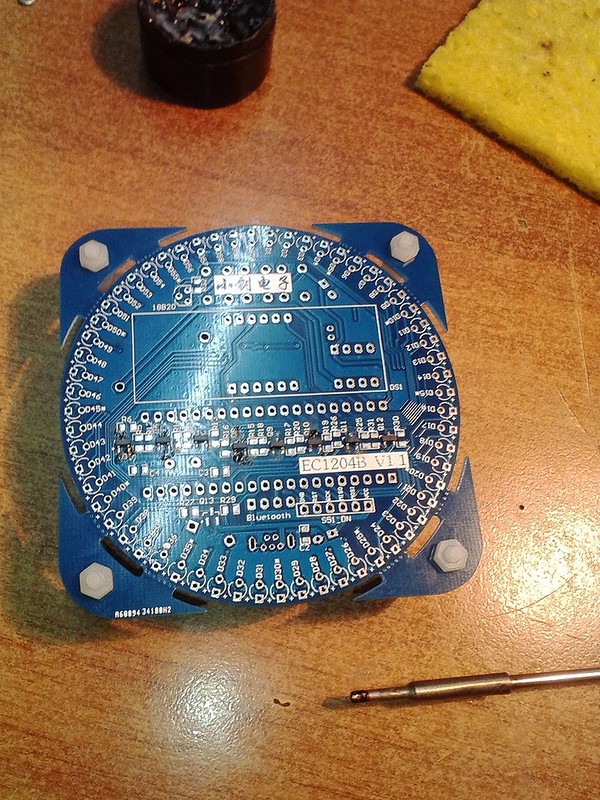
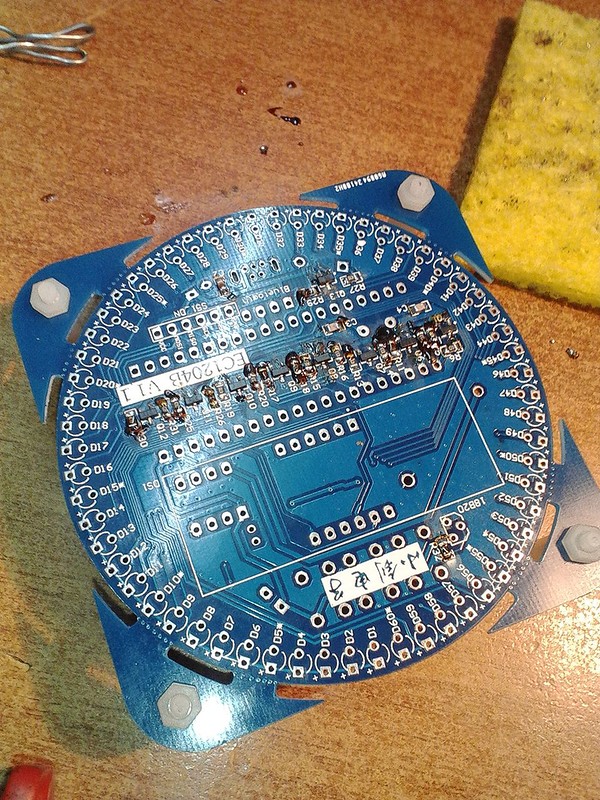
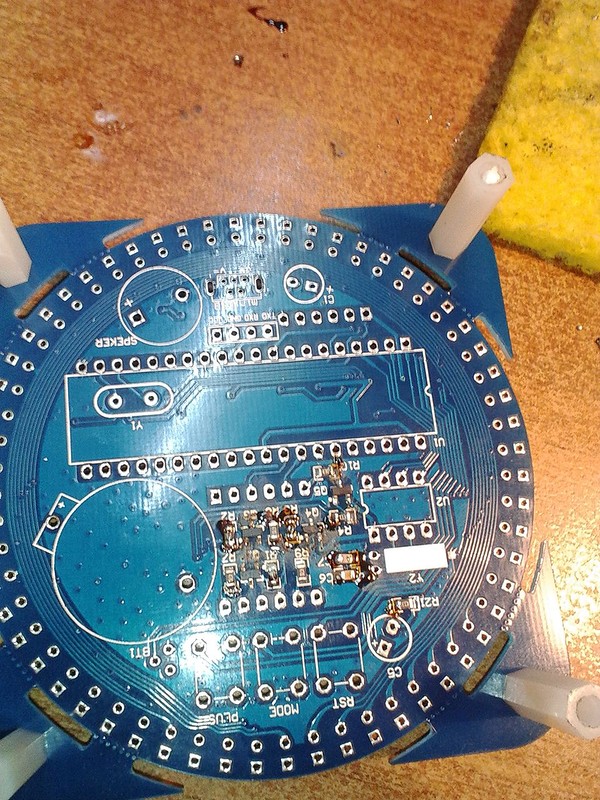
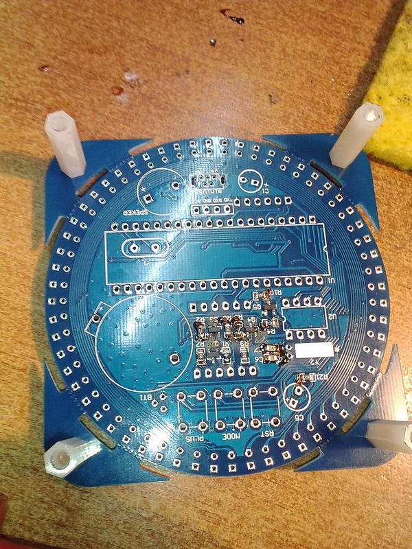
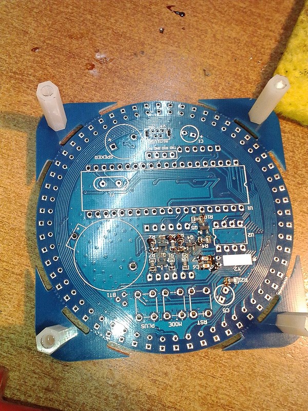
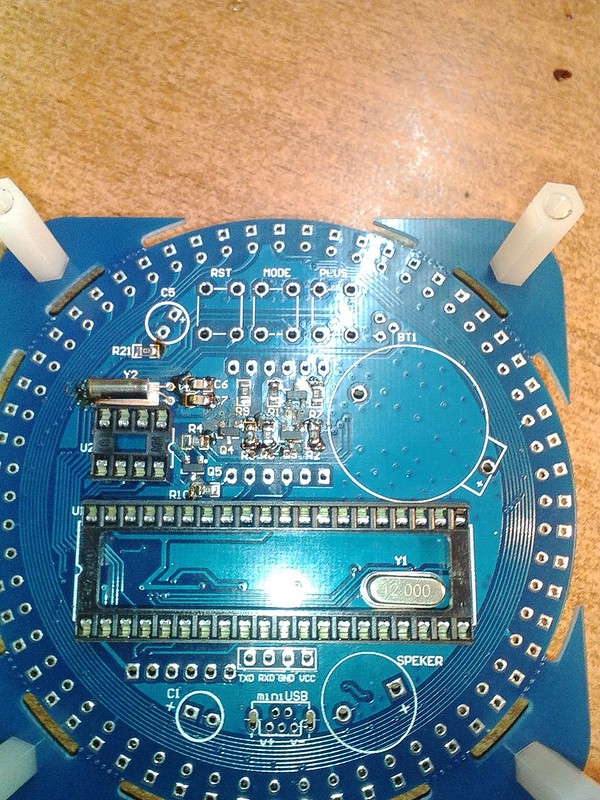
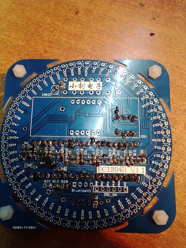
Сначала решил запаять всю SMD’у
Вкрутил комплектные нейлоновые стойки для устойчивости и удобства при сборке.
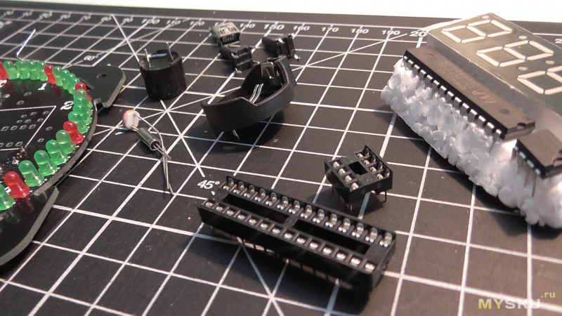
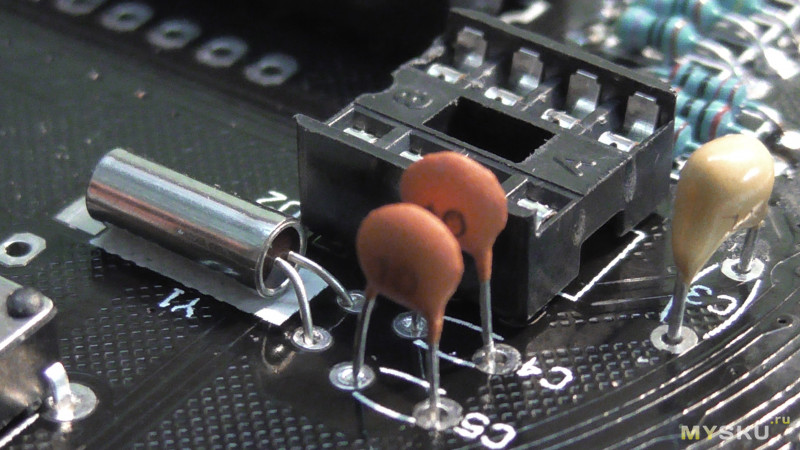
Кварцы, кроватки
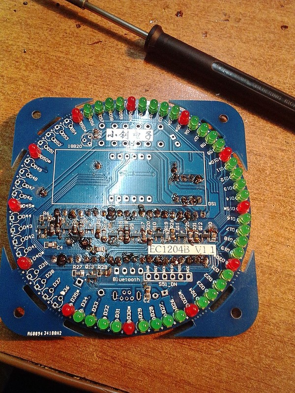
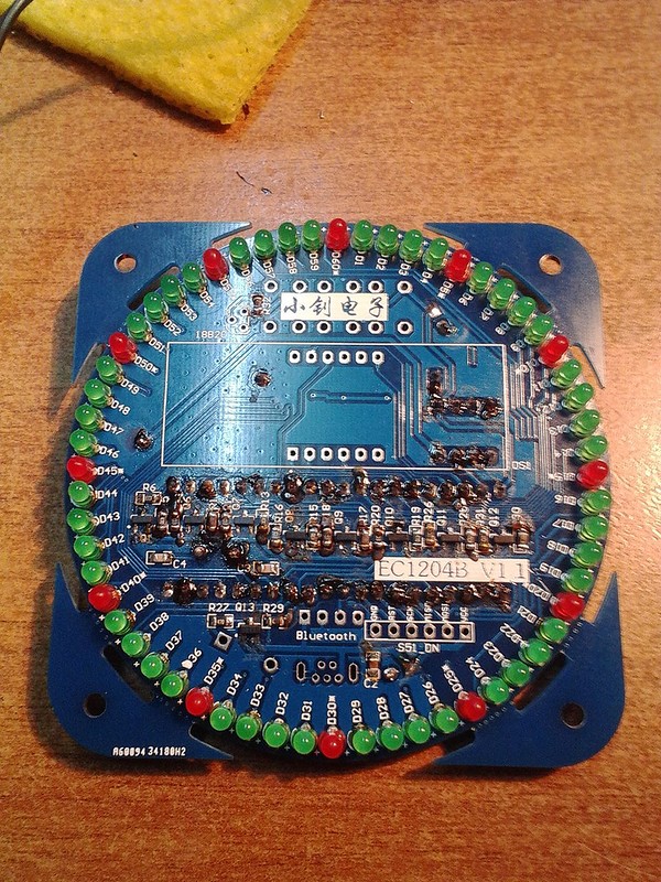
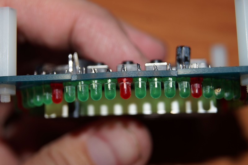
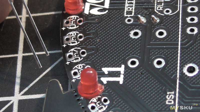
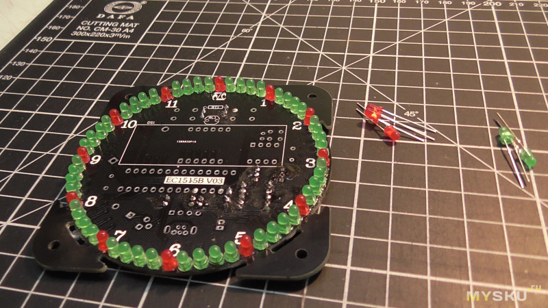
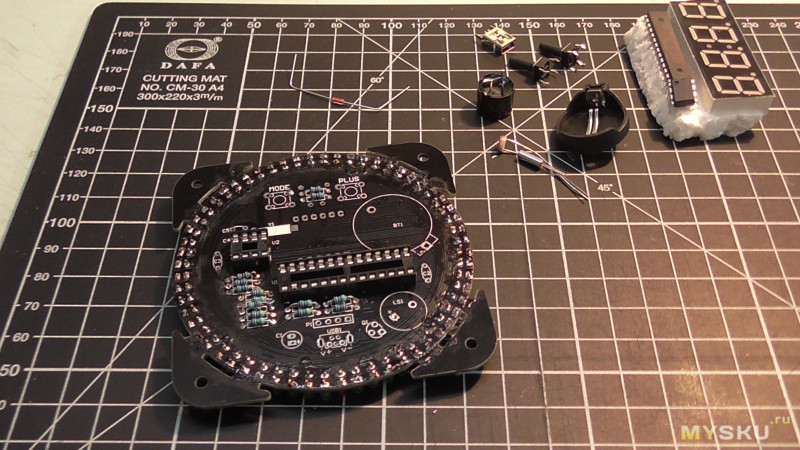
Основная тягомотина это запаивание светодиодов
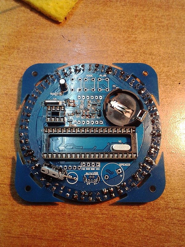
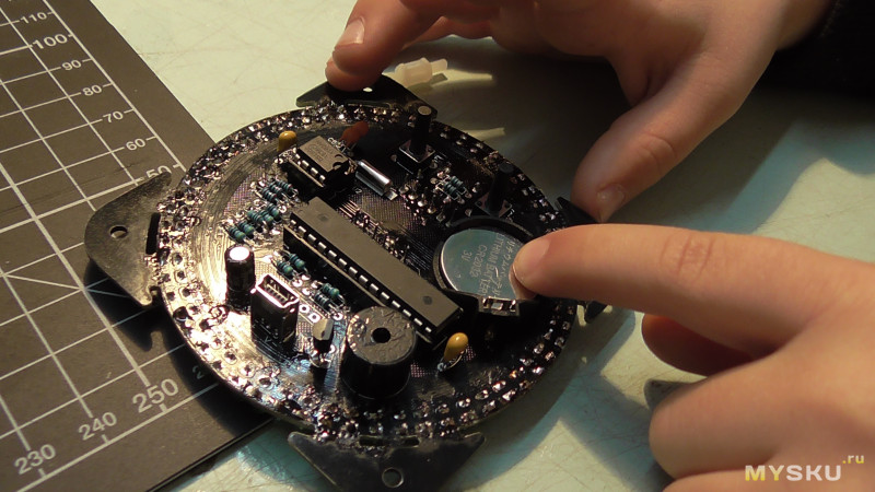
Гребенку под программирование контроллера запаивать не стал, ибо хз что в него шить и чем, а вот внешний вид портит. Также наверное многие заметили место под блютус — в продвинутых версиях модуль идет в комплекте. Есть ли поддержка в этой прошивке — неизвестно.
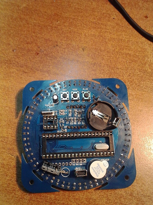
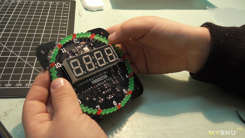
Индикатор, кнопки и пищалку запаял после промывки.
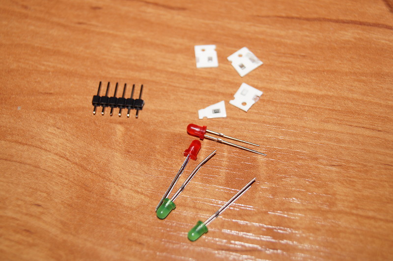
Остатки
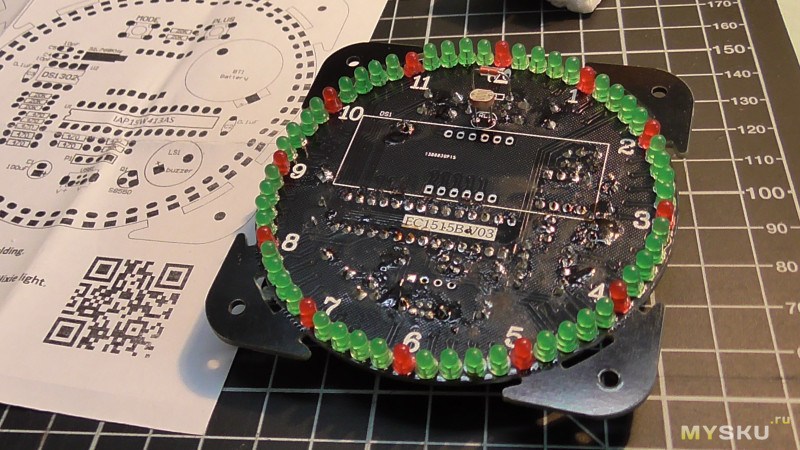
Собранные
Кое-где остался белесый налет от спирта. Мыл медицинским, ибо другого не имею.
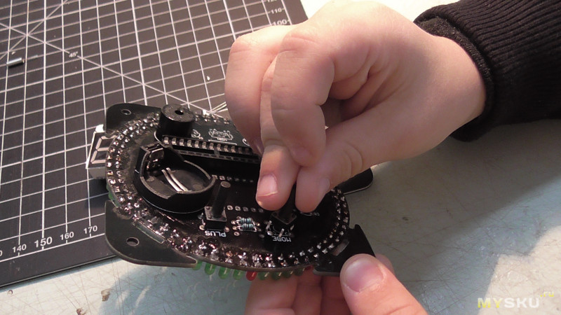
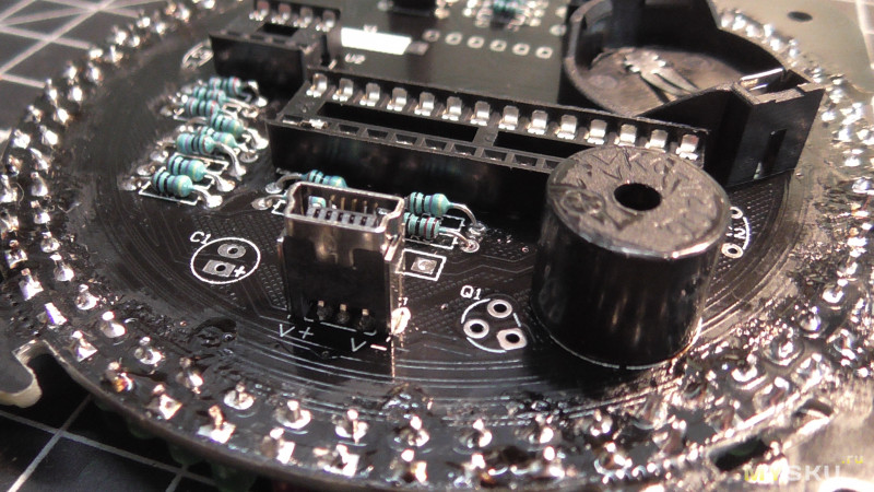
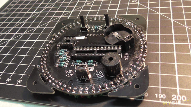
Конденсатор не стал загибать и зря — мешает при нажатии кнопок. Но ноги откушены и фарш не провернешь назад.
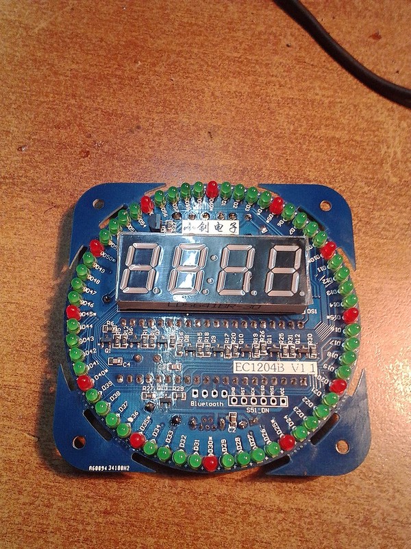
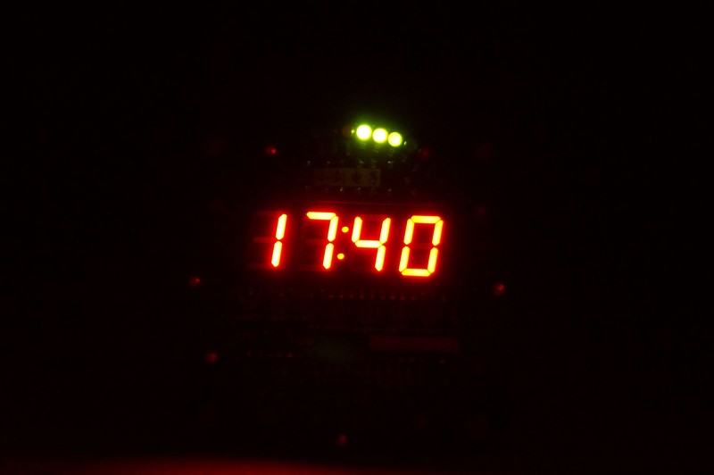
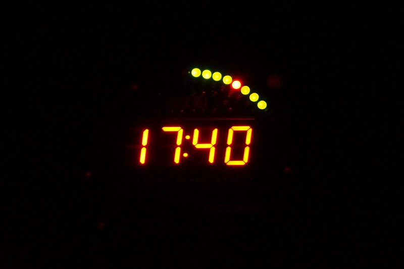
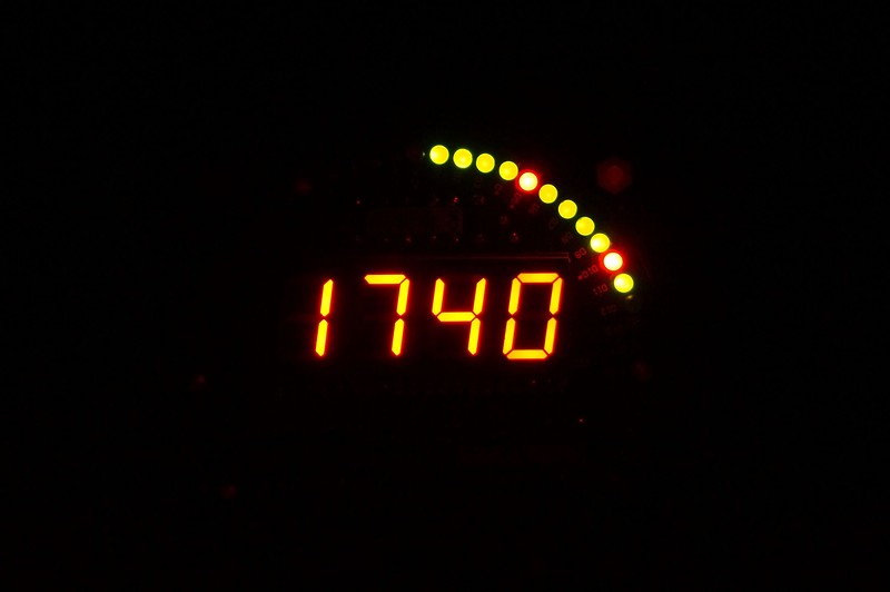
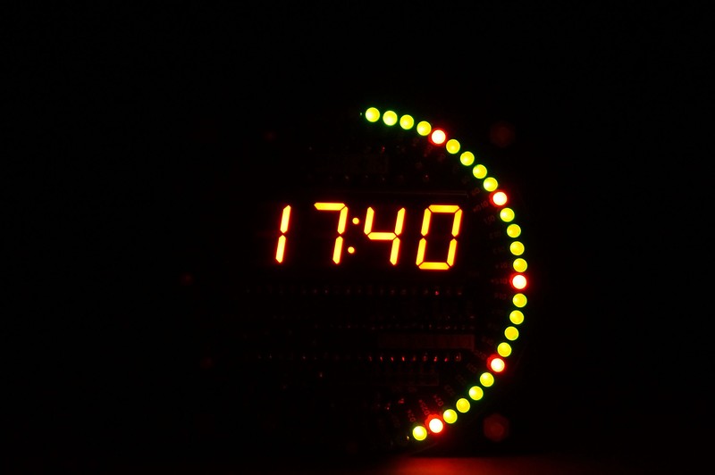
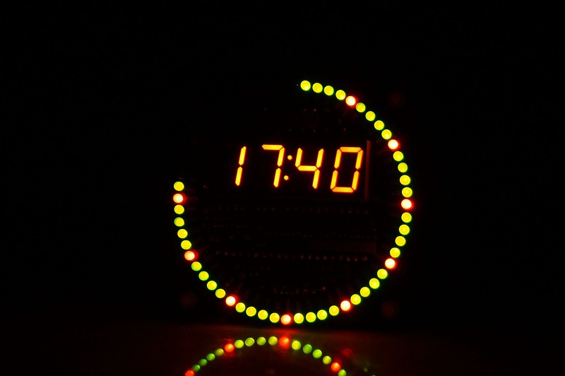
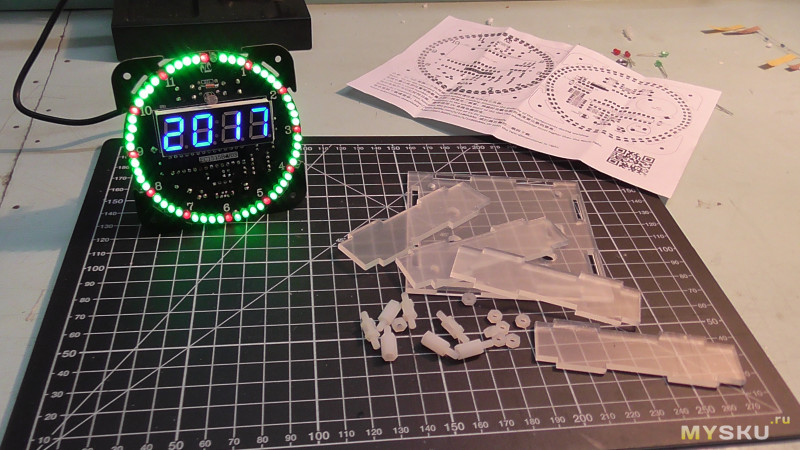
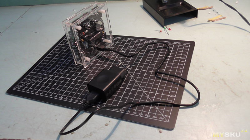
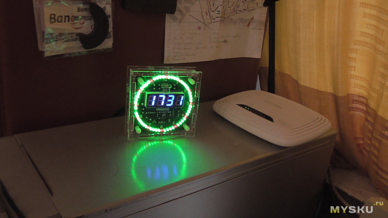
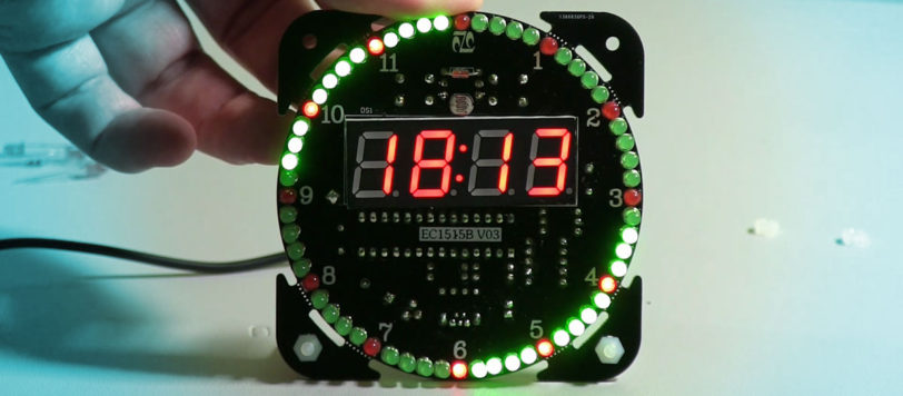
В работе.
Три кнопки, одна ресет, две другие для управления.
Будильник громкий, орет 10 минут если не трогать.
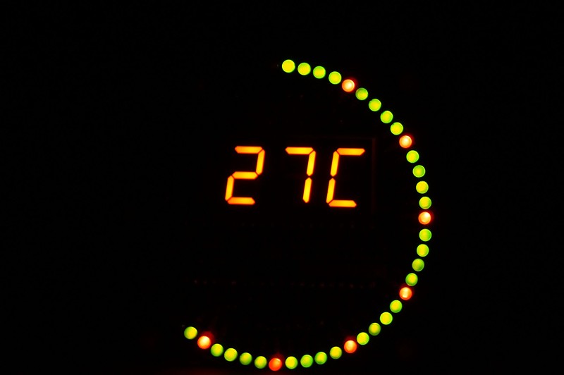
Температуру показывает 10 секунд после нажатия кнопки. Это конечно недоработка, хорошо если бы могли показывать температуру попеременно с временем.
Секунды имеют четыре режима. Все можно посмотреть на видео.
Температура
Видео. Пока снимал запутался что снял, а что нет, так что некоторые повторяются.
Итог: необычные, красивые часы. Классный вариант для подарка как в наборе, так и в собранном виде. Инструкция, даташит и схема есть на странице товара. Ценник на сабж здесь самый низкий, можете даже не искать.
Собирал с паяльником из моего предыдущего обзора.
Спасибо за внимание! Надеюсь обзор понравился и оказался полезным.
UPD: полезный архив с мануалами, прошивкой и пр. yadi.sk/d/YGYatYFAdegR9
предоставил товарищ virusbin
Всем привет, в этом обзоре я с ребятами соберем набор электронных часов.
Часы питаются от 5V что позволяет из подключить к USB разъему компьютера или блока питания.
Мимо часов и даты можно наблюдать температуру в комнате + присутствует будильник.
Пока занимался своими делами ребята успели распаковать посылку с часами и начать их сборку.
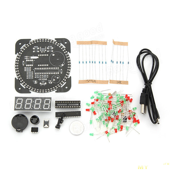
Комплектация:
— печатная плата
— резисторы 470 Ом. — 9 шт. ( 1 шт. лишняя)
— резисторы 20 кОм. — 7 шт. ( 1 шт. лишняя)
— конденсатор электролитический 10 V 100 mF. — 1 шт.
— конденсаторы постоянные 0,1 — 2 шт.
— конденсаторы постоянные 10pF — 2 шт.
— кварц 32,768 кГц
— светодиоды 2 мм. 3 V.
— красные — 15 шт.(3 шт. лишних, пойдут в элементную базу)
— зеленые — 50 шт. (2 шт. лишних, пойдут в элементную базу)
— панельки под микросхемы
— микросхема IAP15W413AS
— микросхема DS1302
— терморезистор
— семисегментный светодиодный индикатор
— слот под батарейку
— батарейка СR2032
— спикер
— miniUSB гнездо
— USB шнур
— микрики — 2 шт.
— схема расположения деталей на плате (принципиальной схемы нет).
— детали для сборки корпуса часов
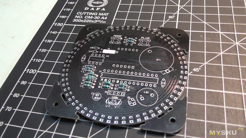
Приступили с припайки резисторов.
Резисторы и остальные компоненты припаиваем с той стороны платы где нанесено их обозначение.
Светодиоды матового цвета в диаметре 2 мм. с напряжением питания 3 V.
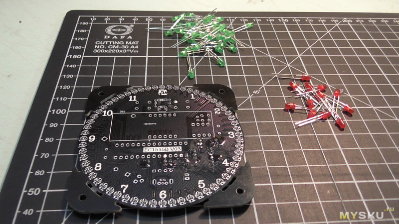
Как видим светодиоды разложены в две кучки красные, зеленые.
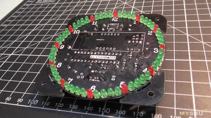
— красные припаиваем на часовые цифры 1,2,3,4… 10,11,12.
— зеленые припаиваем между часовыми цифрами, то есть на минуты.
При установке двух ножек светодиода внимательно смотрим цоколевку, где плюсовая ножка, где минусовая.
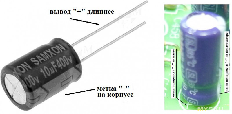
Ножка та что подлиннее это плюс, соответственно смотрим плюсовой пятачок на плате.
Светодиоды на месте, в итоге имеем 5 лишних, похоже их по весу раскладывают у пакеты.
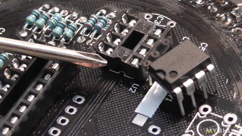
Далее, ставим и припаиваем панельки под микросхемы.
При установке панелек соблюдаем правильность по «ключу» нарисованному на плате.
Микросхемы еще не устанавливаем!
Припаиваем две кнопки «микрики».
— кнопки необходимые для установки время и даты, а также для выбора заставки (типы заставок я демонстрирую на видео которое находится в конце обзора).
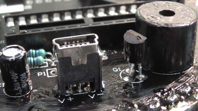
Установили и припаяли «спикер» и гнездо miniUSB.
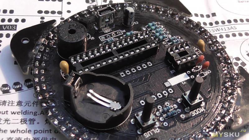
Лицевая сторона платы.
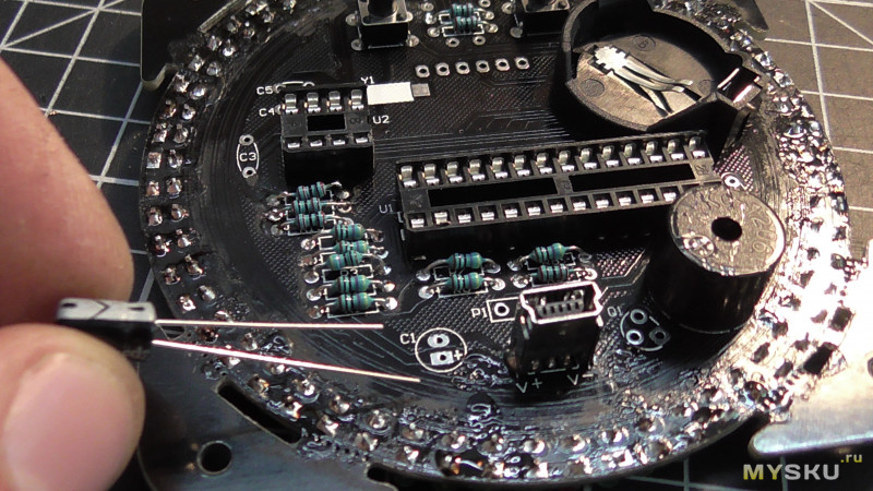
В комплекте находится лишь один электрический конденсатор, который сейчас мы установим на свое место.
На месте установки конденсатора имеется обозначения (+) естественно туда ставим ножку конденсатора та что подлиннее, если ножки одинаковой длины, на конденсаторы будет метка (-) естественно ниже которой будет минусовая ножка, а рядом второй отвод плюсовой.
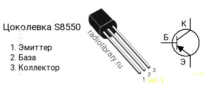
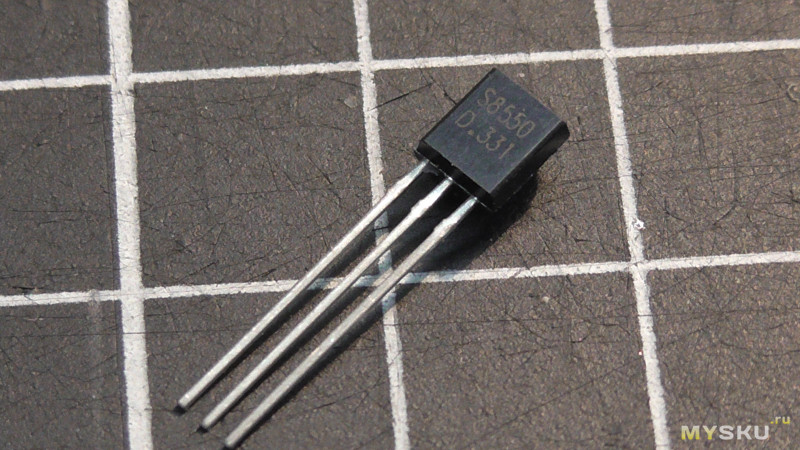
Так же в комплекте находится один единственный транзистор S8550
Расположение на плате.
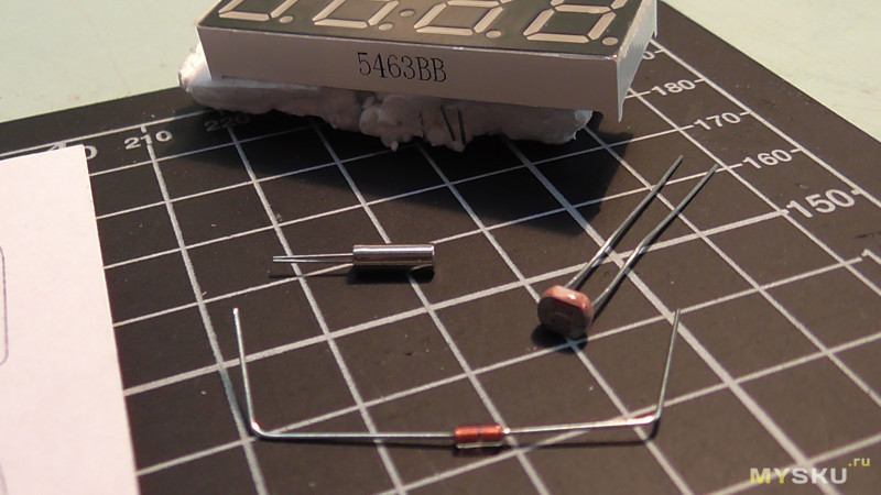
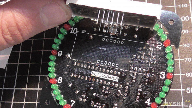
Остается припаять терморезистор NTC MF58, фоторезистор, кварц 32,768 кГц и часовой LED дисплей.
В комплекте получаем кварц:
— частота 32,768 кГц
— размеры 2×6 мм
Электронная часть часов состоит из генератора колебаний собранного в микросхеме DS1302 которая стабилизирована кварцевым генератором
Частота колебаний генератора, как правило, равна 32 768 Гц.
Характеристики микросхемы DS1302:
Считает секунды, минуты, часы, день недели, день месяца, месяц, год с учетом високосных лет до 2100года
Отображение времени в 12 или 24 часовом видах с отображением AM или PM
Питание может находится в диапазоне 2.0 — 5.5В
При 2В потребляет ток меньше 300нА
Простой 3-х проводный интерфейс
Рабочий диапазон температур: -40…+850С
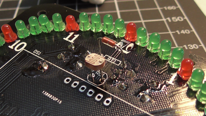
На лицевой стороне платы установили терморезистор и фоторезистор.
Которые необходимые для:
Терморезистор — это резистор, сопротивление которого сильно изменяется в зависимости от температуры, то есть, он нам необходим для измерения температуры в комнате, которая будет отображена на индикаторе часов.
Фоторезистор — это резистор, электрическое сопротивление которого изменяется под влиянием световых лучей, падающих на светочувствительную поверхность, то есть, он нужен часам для уменьшения яркости светодиодов у дневное время.
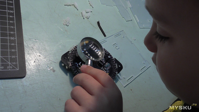
Осмотр)))
Если отключить USB питание часов, часы будут работать благодаря установленной батарейке СR2032 3V но при этом ни один светодиод на часах светится не будет.
Все в порядке, дефектов (соплей) не обнаружено.
Устанавливаем микросхемы.
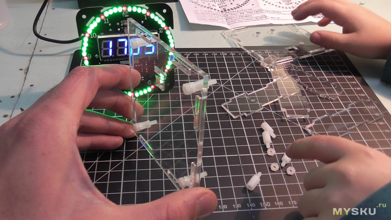
Пора собрать корпус.
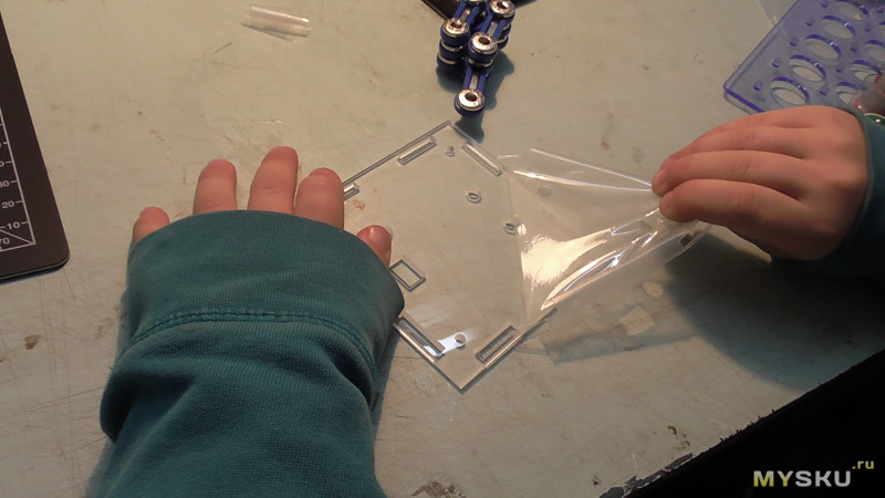
Изначально я подумал что пластик матовый, но ребята обнаружили на деталях пленку которую желательно содрать.
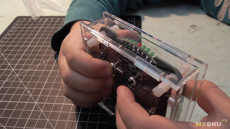
На задней стороне часов имеем две кнопки для настройки часов, даты и выбора режима работы светодиодов.
Меню часов активируется зажатием одной кнопки «MODE»
— первый пункт — вкл/выкл сигнала бузера
— второй пункт — можно задать время из скольких будет пищать почасовой бузер.
— третий пункт — задаем по какое время будет пищать почасовой бузер.
— четвертый пункт — задаем мелодию которая будет звучать с новым начинающим времинем.
— пятый пункт — активация будильника
— шестой пункт — установка времени срабатывания будильника
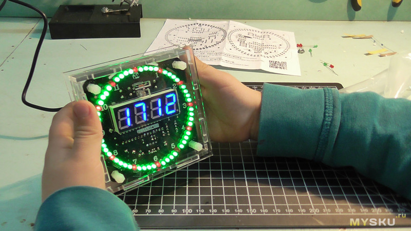
Итог, сам не ожидал что получится такая красота тем более полезная для дома, видим время, дату и температуру в комнате.
В итоге, я остался доволен что ребятам понравилось собирать данный набор, правда без моей помощи не обошлось, ну и то, я очень доволен что их заинтересовал пайкой.
Спикер сигналит о начале нового часа.
Светодиодный круг может работать в различных режимах которые показаны ниже на видео.
Могу рекомендовать для завлечения ребенка к пайке, к тому же результат ребенка порадует.
Плюсы набора;
— полный пакет необходимых компонентов для сборки часов
— красивый прозрачный корпус
— отлично проведенное время с ребенком
— сигнал о наступлении нового часа (правда ночью будит)
— сохранение времени при отключении питания
— настройка времени будильника
Минусы:
— в комплект не идет USB блок питания
Видео работы часов, а также, режимы работы светодиодного круга.
На видео заметное мерцание светодиодов, в реале его нет, это просто несовпадение частоты кадровки камеры и частоты динамической индикации светодиода.
Товар предоставлен для написания обзора магазином. Обзор опубликован в соответствии с п.18 Правил сайта.
Disappointed with my earlier watch kit SSY-SZ04 I have ordered a similar watch kit EC1515B V03 and would like to share my experience with it.
digital and analog watch in harmony
Today I report on a consistently successful soldering project: with the help of a well-recognizable documentation and sufficient components, the soldering work is done with a time of 1-2 hours.
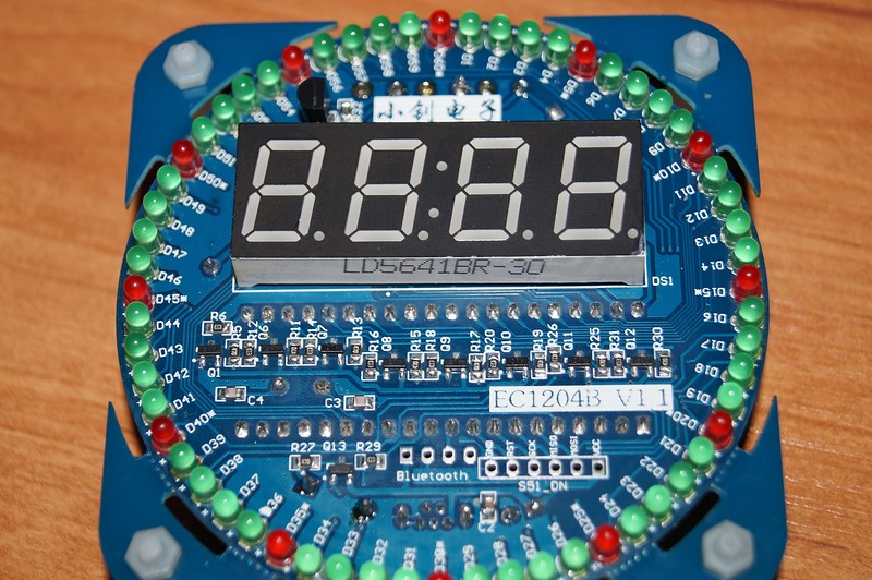
1 / 3 • front documentation with 3 components: thermistor, photoresistor and 7-segment display
#1 — preparation
I put all the components on a sheet of paper and sort it first. In the process, I also get to know unknown components and look up what a well-known search engine has to report about it. In doubt, i look in the circuit diagram, how many components of it are to be installed and can then deduce the amount that I am right.
do I have all components?
«10» = 10pF = position C4 and C5 on PCB.
«104» = 0,1uF = position C2 and C3 on PCB.
Remember: C1 = 100uF polarized (double check + and -)
remove screws from the 3D printer to attach the transparent frame, if ordered
full components in the overview
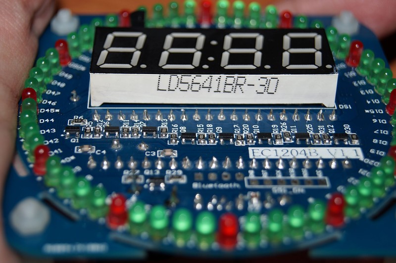
front-side: RL1 = photoresistor and RT1 = thermistor and 7-segment-display
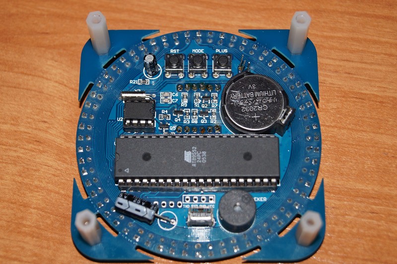
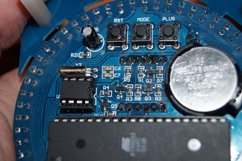
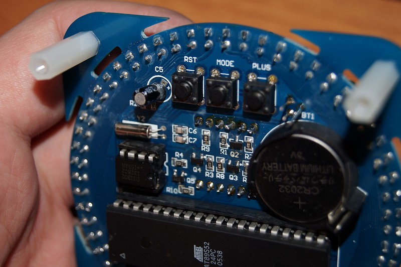
back-side: Q1 = S8550, U1 = IAP-Chip and U2 = DS1302, Y1 = 32,768KHz
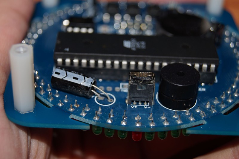
Remember: USB1, LS1 (Buzzer) and BT1 (Battery) are polarized (double check + and -)
#2 — Soldering
I started with the red LED on the front side and then gradually soldered on the other elements.
RT1 is an thermistor an the front-side
#3 — Test
The final result with a composite frame (remembering the buffing of a protective film on the individual pieces both on the front and on the back) can be subjected to a first test.
For 12.50 Euros not a very cheap DIY kit, but the chic LED modes compensate for the hobbyist’s heart. My wife would not put it in the living room (too much BlinkyBlinky) — so on the desk.
Link to the transparent frame:
http://www.dx.com/p/acrylic-case-for-upgrade-version-led-rotation-electronic-clock-kit-436243#.WsOo12b5wU0
#4 — Modes
#5 — Setting time and functions
Note: decisive for the settings is the holding mode: with 3 seconds you come in the settings for the alarms; with 5 seconds you have influence on other options:
- 1 — light control (impact to brightness)
- 2 — photos witching level set -?
- 3 — Fahrenheit / Celsius switch
- 4 — temperature calibration set (-10 / + 10) (impact to the displayed temperature)
- 5 — 12/24 hour display set
- 6 — time display set (which information scroll over the display from 00 only time over 01 with date to 02 with all information)
- 7 — LED auto switch display set (00/85) -?
2 Oct 2016
In this video I build an electronic clock kit! I attempt to do it with a cheap USB soldering iron, but don’t last long before switching back to the Hakko. I also offer a few soldering tips and useful tools and gear.
It’s a decent little clock with animated LEDs, time, date, temperature, and light sensor.
*This is an unpaid, non-sponsored review*
Schematic and PCB layout
These files were originally available from a Chinese Baidu website, but it was a bit hit-and-miss and Firefox had the domain marked for malware! I’ve since made these files available directly to make them more convenient to access:
- EC1515B Operation Instructions V02 (PDF)
- EC1515B Schematic V03 (PDF)
- EC1515B Kit Manual (JPG)
- EC1515B PCB Front (JPG)
- EC1515B PCB Back (JPG)
Further information
- EC1515A clock kit from Deal Extreme
- Laser cut enclosure from Deal Extreme
About the Author: Darian Cabot
Hardware and software engineer with experience in product development and building automation. Director at Cabot Technologies and Product Manager at NEX Data Management Systems.
-
Contents
-
Table of Contents
-
Bookmarks
Quick Links
Related Manuals for EDAN SE-1515
Summary of Contents for EDAN SE-1515
-
Page 2: About This Manual
This manual will help you understand the operation and maintenance of the product better. It is reminded that the product shall be used strictly complying with this manual. User’s operation failing to comply with this manual may result in malfunction or accident for which EDAN INSTRUMENTS, INC. (hereinafter called EDAN) cannot be held liable.
-
Page 3
WARNING A WARNING label advises against certain actions or situations that could result in personal injury or death. CAUTION A CAUTION label advises against actions or situations that could damage equipment, produce inaccurate data, or invalidate a procedure. NOTE A NOTE provides useful information regarding a function or a procedure. -
Page 4: Table Of Contents
1.2.5 Contraindications (for Exercise ECG) …………..7 1.3 List of Symbols ……………………8 Chapter 2 Introduction …………………… 10 2.1 Wired SE-1515 System ………………… 11 2.1.1 Wired System Connection Diagram ……………. 11 2.1.2 Assembling the Wired System …………….12 2.1.3 ECG Sampling Box ………………..13 2.2 Wireless SE-1515 System ………………..
-
Page 5
4.2.2 Entering Patient Information by Using a Bar Code Reader ……..39 4.2.3 Retrieve Patient Information ………………. 39 4.3 Selecting the ECG Sampling Type ………………39 4.4 ECG Sampling ……………………40 4.4.1 Resting ECG Sampling ………………. 40 4.4.2 STAT ECG ………………….. 47 4.4.3 Exercise ECG Sampling ……………… -
Page 6
6.1.8 Export ……………………73 6.2 Order List …………………….. 74 6.2.1 New Order ………………….. 74 6.2.2 Inbox ……………………74 6.2.3 Searching Information ………………… 74 Chapter 7 Statistics ……………………75 Chapter 8 System Setup ………………….. 76 8.1 Basic Setup ……………………76 8.2 Display Setup ……………………77 8.3 Transmission Setup …………………. -
Page 7
Appendix 2 EMC Information ………………..99 Appendix 3 Abbreviations ………………….103… -
Page 8: Chapter 1 Safety Guidance
This chapter provides important safety information related to the use of SE-1515. 1.1 Indications for Use/Intended Use SE-1515 PC ECG is intended to acquire, process and store ECG signals from adult and pediatric patients undergoing stress exercise test or resting test. The SE-1515 PC ECG is intended to be used only in hospitals and healthcare facilities by doctors and trained healthcare professionals.
-
Page 9
SE-1515 PC ECG User Manual Safety Guidance WARNING 2. Only qualified service engineers can install this equipment, and only service engineers authorized by the manufacturer can open the shell. Otherwise, safety hazards may happen. 3. EXPLOSION HAZARD — Do not use the system in the presence of flammable anesthetic mixtures with oxygen or other flammable agents. -
Page 10
IEC/EN 60601-1. 26. Make sure that there is no intense electromagnetic interference source around when using the wireless system of SE-1515. Furthermore, keep an unobstructed distance of at most 5 meters between DX12 transmitter and the PC. -
Page 11: General Cautions
SE-1515 PC ECG User Manual Safety Guidance WARNING 27. You should purchase computer, printer, treadmill, ergometer, BP monitor and bar code reader from the manufacturer. Otherwise, the manufacturer will not be held responsible for the maintenance of the PC hardware, operating system and other accessories.
-
Page 12: Operation Warnings For Wireless System
SE-1515 PC ECG User Manual Safety Guidance CAUTION 3. Make sure that there is no intense electromagnetic interference source around the equipment, such as radio transmitters or mobile phones etc. Attention: large medical electrical equipment such as electrosurgical equipment, radiological equipment and magnetic resonance imaging equipment etc.
-
Page 13: Preparation And Operation Warnings (For Exercise Ecg)
SE-1515 PC ECG User Manual Safety Guidance WARNING 9. Properly dispose of or recycle the depleted battery according to local regulations. 10. Remove the battery from the transmitter if the system won’t be used for a long time. 1.2.4 Preparation and Operation Warnings (for Exercise ECG) WARNING 1.
-
Page 14: Contraindications (For Exercise Ecg)
SE-1515 PC ECG User Manual Safety Guidance 1.2.5 Contraindications (for Exercise ECG) Absolute Contraindications: 1. Acute MI (within 2 days) 2. High-risk unstable angina 3. Hemodynamic compromise caused by uncontrolled cardiac arrhythmia 4. Symptomatic severe aortic stenosis 5. Heart failure with clinic episode uncontrolled 6.
-
Page 15: List Of Symbols
SE-1515 PC ECG User Manual Safety Guidance 1.3 List of Symbols Symbol Description DEFIBRILLATION-PROOF TYPE CF APPLIED PART Caution Operating instructions General symbol for recovery/recyclable Part Number SERIAL NUMBER Date of manufacture MANUFACTURER CLASS II equipment AUTHORISED REPRESENTATIVE IN THE EUROPEAN…
-
Page 16
SE-1515 PC ECG User Manual Safety Guidance Start printing button (on DE15&DE18) CE marking Disposal method Caution: Federal (U.S.) law restricts this device to sale by or on the order of a physician. Federal Communications Commission: FCC ID:SMQDX12TREDAN (for DX12 Transmitter) -
Page 17: Chapter 2 Introduction
SE-1515 PC ECG User Manual Introduction Chapter 2 Introduction The SE-1515 system consists of the following equipment: 18-lead ECG sampling system (18-lead ECG sampling box) Or, 16-lead ECG sampling system (16-lead ECG sampling box) Or, 12-lead wired ECG sampling system (12-lead ECG sampling box) Or, 12-lead wireless ECG sampling system (wireless DX12 transmitter and receiver) …
-
Page 18: Wired Se-1515 System
SE-1515 PC ECG User Manual Introduction 2.1 Wired SE-1515 System 2.1.1 Wired System Connection Diagram 1. Resting ECG of Wired SE-1515 System 2. Exercise ECG of Wired SE-1515 System — 11 -…
-
Page 19: Assembling The Wired System
SE-1515 PC ECG User Manual Introduction 2.1.2 Assembling the Wired System The DE15 ECG sampling box is used as an example here: Patient Cable DE15 ECG sampling box Resting ECG Cable Exercise ECG Cable Assembly Drawing — 12 -…
-
Page 20: Ecg Sampling Box
SE-1515 PC ECG User Manual Introduction 1) Insert plug 1 of the patient cable into socket 2 of DE15 ECG sampling box. 2) Insert plug 7 of the cable into socket 3 of DE15 ECG sampling box. 3) Insert plug 8 of the cable into the USB socket of the PC.
-
Page 21: Wireless Se-1515 System
SE-1515 PC ECG User Manual Introduction 2.1.3.2 DP12 ECG Sampling Box Front Panel Indicator USB Interface Name Explanation When the ECG sampling box is powered by the PC, the Indicator indicator will be lit. USB Interface Connecting to the USB socket of the PC with a USB cable 2.2 Wireless SE-1515 System…
-
Page 22
SE-1515 PC ECG User Manual Introduction receiver is connected. Consult the dealer or an experienced radio/TV technician for help. Any changes or modifications to this unit not expressly approved by the party responsible for compliance could void the user’s authority to operate the equipment. -
Page 23
SE-1515 PC ECG User Manual Introduction 1 Resting ECG of Wireless System 2 Exercises ECG of Wireless System NOTE: The manufacturer is not responsible for any radio or TV interference caused by unauthorized modifications to this equipment. such modifications could void the user’s authority to operate this equipment. -
Page 24: Assembling Wireless System
4. DX12 transmitter of the wireless system uses the Bluetooth technology, which could make the patient with the pacemaker uncomfortable. Keep DX12 transmitter far away from the pacemaker when using the wireless system of SE-1515. 2.2.2 Assembling Wireless System Patient Cable…
-
Page 25
SE-1515 PC ECG User Manual Introduction Resting ECG Cable Exercise ECG Cable Burglar Lock DX12 Belt Assembly Drawing 1) Insert plug 1 of the patient cable into socket 2 of DX12 transmitter. 2) Insert DX12 transmitter into pocket 3 of DX12 belt, and then wear the belt around the waist. -
Page 26: Ecg Sampling Box
SE-1515 PC ECG User Manual Introduction 6) Connect a treadmill or an ergometer to the PC (for exercise ECG only). 7) Connect a printer to the PC.
Insert the Sentinel into the USB socket of the PC if the sentinel is purchased.
-
Page 27
SE-1515 PC ECG User Manual Introduction Button Explanation Switch on DX12 receiver and install batteries on DX12 transmitter. Press the button to start up DX12 transmitter, the main screen will be displayed.. When the main screen is displayed, press the button to return to previous menu. -
Page 28: Installing The Software
SE-1515 PC ECG User Manual Introduction Back Light Select On to turn on the backlight of LCD screen. Select Off to turn off the backlight of LCD screen. Auto Sleep Select On to display Sleeping on the screen and make DX12 transmitter be in low power consumption mode after lead off for 5 minutes.
-
Page 29: About Installation Window
Insert the installation CD into CD-ROM, double-click on Setup.exe and then follow the directions to finish the installation. For details on installing SE-1515 software, please refer to SE-1515 PC ECG Installation Guide. 2.4 Features 3-/6-/9-/12-/15-/16-/18-channel ECG waves are displayed and printed …
-
Page 30
SE-1515 PC ECG User Manual Introduction Storing massive patient data in the computer, which enables you to review and analyze the exercise ECG in any time Automatically controlling and adjusting the speed and the elevation of the treadmill … -
Page 31: Chapter 3 Preparations Before Operation
SE-1515 PC ECG User Manual Preparations Before Operation Chapter 3 Preparations Before Operation 3.1 Preparing the Patient NOTE: Correct operation for the best-quality ECG is very important. 3.1.1 Instructing the Patient 1. Before attaching the electrodes, greet the patient and explain the procedure. Explaining the procedure decreases the patient’s anxiety.
-
Page 32: Connecting The Electrodes Of Wired System
SE-1515 PC ECG User Manual Preparations Before Operation WARNING The performance and electric shock protection can be guaranteed only if the original patient cable and electrodes of the manufacturer are used. 3.2 Connecting the Electrodes of Wired System Connecting to…
-
Page 33: Connecting The Electrodes Of Wireless System
SE-1515 PC ECG User Manual Preparations Before Operation 3.3 Connecting the Electrodes of Wireless System Connecting to the ECG Sampling Box Connecting to Electrodes Main Cable Lead Wires Patient Cable (Snap Style) Lead Wires Main Cable Connecting to Connecting to…
-
Page 34: Attaching Electrodes
SE-1515 PC ECG User Manual Preparations Before Operation 3.4 Attaching Electrodes 3.4.1 Attaching Electrodes for Resting ECG WARNING Make sure that the conductive parts of electrodes and associated connectors, including neutral electrodes, do not come in contact with earth or any other conducting objects.
-
Page 35
SE-1515 PC ECG User Manual Preparations Before Operation White/Yellow Brown/Yellow Light blue/Violet/ Orange/Violet Light blue/ Yellow Orange/Yellow Light blue/ Red Orange/ Red Light blue/ Black Orange/Black Standard 12-Lead Placement Only for the Reusable Electrodes Only for the Disposable Electrodes… -
Page 36
SE-1515 PC ECG User Manual Preparations Before Operation Right arm/Right deltoid Left leg/Upper leg as close to torso as possible Right leg/Upper leg as close to torso as possible Standard+XYZ Electrode Placement Fourth intercostal space at the right border of the sternum… -
Page 37
SE-1515 PC ECG User Manual Preparations Before Operation Back of neck, avoid the carotid artery and jugular vein. Mid-sternum on the same horizontal level as C4 and C6. Right mid-axillary line on the same horizontal level as C4 and C6. -
Page 38
SE-1515 PC ECG User Manual Preparations Before Operation Right leg/Upper leg as close to torso as possible NEHB Placement Electrode Placement /C3R A1/V3R Attachment point of the second rib to the right sternal edge /C4R A2/V4R Fifth intercostal space on the left posterior axillary line Left mid-clavicular line in the fifth intercostal space … -
Page 39: Electrode Placement For Exercise Ecg
SE-1515 PC ECG User Manual Preparations Before Operation V7+V8+V9 (Back) DE18: Electrode Placement Left posterior axillary line on the same horizontal level as C4 and C6 Left midscapular line on the same horizontal level as C4 and C7 Left paraspinal border on the same horizontal level as C4 and C8…
-
Page 40: Attaching The Reusable Electrodes
SE-1515 PC ECG User Manual Preparations Before Operation The Precordial Electrodes’ Positions on Body Surface: Electrode Placement Fourth intercostal space at the right border of the sternum Fourth intercostal space at the left border of the sternum Fifth rib between C2 and C4…
-
Page 41: Attaching Disposable Electrodes
SE-1515 PC ECG User Manual Preparations Before Operation 3.4.3.2 Attaching the Chest Electrodes Suction Bulb Connecting to a Lead Wire Metal Cup Chest Electrode Chest Electrode Connection: Ensure that the electrodes are clean; Clean the electrode area on the chest surface with 75% alcohol;…
-
Page 42: Inspection Before Test
SE-1515 PC ECG User Manual Preparations Before Operation 2) Clean the electrode areas on the body surface with 75% alcohol. 3) Attach the disposable electrodes to the electrode positions on the body surface. 4) Clip the disposable electrodes with the alligator clips.
-
Page 43
SE-1515 PC ECG User Manual Preparations Before Operation 2) Power Supply: Check whether the power cord is connected well. The grounded outlet should be used. 3) Ground Connection Check whether the ground cable is firmly connected. 4) Patient Cable: Check whether the patient cable is connected to the ECG sampling box firmly, and keep it far away from the power cord. -
Page 44: Chapter 4 Ecg Sampling
SE-1515 PC ECG User Manual ECG Sampling Chapter 4 ECG Sampling Plug in the right sentinel, and double-click on the screen to start the software. The main screen will be displayed as follows: Figure 4-1 Main screen 4.1 Initial Configuration When the software is started the first time after installation, an Initial Setting window will be displayed, and you can configure parameters such as the hospital name, lead mode, and sequence.
-
Page 45: Entering Patient Information Manually
If Pacemaker is selected on the Display Setting window, a checkbox for the pacemaker will be provided on the New Patient window. If Pacemaker is selected, SE-1515 is very sensitive and can detect very small pacemaker pulses. Therefore, SE-1515 should be placed far from the devices emitting high frequency radiation to avoid interferences on the pacemaker pulse detection and normal ECG acquisition.
-
Page 46: Entering Patient Information By Using A Bar Code Reader
NOTE: If the two-dimensional bar code reader is used, you should install Symbol COM Port Emulation Driver manually. For details, please refer to SE-1515 PC ECG Installation Guide. 2. Connect the USB bar code reader to the computer.
-
Page 47: Ecg Sampling
SE-1515 PC ECG User Manual ECG Sampling 4.4 ECG Sampling 4.4.1 Resting ECG Sampling Click on OK after filling out the patient information and selecting the ECG sampling type, the ECG sampling screen will be displayed. NOTE: When placing a new order, if you want to start ECG sampling right after placing the order, select Start examination after order in the Display Setting of System Setting.
-
Page 48
SE-1515 PC ECG User Manual ECG Sampling Once clicked, the New Patient window will be displayed and you can edit the Edit patient information. Once clicked, the frozen window will be displayed. Freeze On the displayed window, you can review the ECG sampled before, and print the displayed ECG by clicking on the Print button. -
Page 49
SE-1515 PC ECG User Manual ECG Sampling 4.4.1.4 Sample Setup Click on Setting on the resting ECG sampling screen, and the System Setting window will be displayed. In the System Setting window, click Sampling Setting to enter the Sampling Setting window. -
Page 50
SE-1515 PC ECG User Manual ECG Sampling І, II, ІІІ, aVR, aVL, aVF, V1, V2, V3, V4, V5, V6, ND, Standard+NEHB NA, NI І, II, ІІІ, aVR, aVL, aVF, V1, V2, V3, V4, V5, V6, X, Y, Standard+XYZ І, II, ІІІ, aVR, aVL, aVF, V1, V2, V3, V4, V5, V6, V3R,… -
Page 51
SE-1515 PC ECG User Manual ECG Sampling all analysis screens. If OFF is selected, the system does not generate any automatic diagnosis results after the sampling is complete. Enter the analysis screen If this function is selected, the system automatically switches to the analysis when sampling screen after the sampling is complete. -
Page 52
SE-1515 PC ECG User Manual ECG Sampling The wave width can be set to 1, 2, 3, 4, or 5. A larger means that the waveforms printed are wider. value NOTE: This parameter affects the printing only, the waveforms displayed on the screen remains the same. -
Page 53
SE-1515 PC ECG User Manual ECG Sampling Parameter Description Enable Vector Once enabled, you can view the vector calculation results on the analysis Calculation screen for resting ECG. NOTE: This function is unavailable in 9-Lead mode and Standard+XYZ mode.. … -
Page 54: Stat Ecg
All operations for the STAT ECG are the same as those for the resting ECG data sampling. 4.4.3 Exercise ECG Sampling NOTE: The exercise test duration of SE-1515 can be as long as 2 hours. Normally, the test duration is within 40 minutes.
-
Page 55
SE-1515 PC ECG User Manual ECG Sampling 4.4.3.1 Buttons NOTE: 1. You can use F1–F9 on the keyboard directly to control the ECG sampling screen. 2. No matter how many changes on the speed or slope you make in a stage, the software only saves the latest one. -
Page 56
SE-1515 PC ECG User Manual ECG Sampling (X<10), the system will print the waveforms in the last Xs. Freeze During the presampling stage and test, Freeze is displayed. Click Freeze and the frozen window will be displayed. Edit/Event During presampling, you can click Edit to open the New Patient window and edit patient information. -
Page 57
SE-1515 PC ECG User Manual ECG Sampling 4.4.3.2 Parameter Information Display Heart rate display Target HR Percentage of the current HR against the target HR Current HR NOTE: 1. If the background color of the current HR displayed is yellow, it indicates that the current HR excesses the target value and should be paid attention to. -
Page 58
SE-1515 PC ECG User Manual ECG Sampling When you click Re-identify after you have manually adjusted the measurement line, the system automatically calculates the place of the measurement line of the Q point and J point and their corresponding ST value and ST slope. The system also refreshes the place of the measurement line of the Q point and J point every 10s. -
Page 59
SE-1515 PC ECG User Manual ECG Sampling 4.4.3.6 Device Setup Click on Settings on the exercise ECG sampling screen, and the System Setting window will be displayed. In the System Setting window, click Device to enter the Device window. Parameter… -
Page 60
SE-1515 PC ECG User Manual ECG Sampling 4.4.3.7 Protocol Editing In the Device window, select a protocol and click Edit to enter the editing window for non-default protocols. In this window, you can change any parameter of each stage or delete the non-default protocols. -
Page 61: Vcg Sampling
SE-1515 PC ECG User Manual ECG Sampling If Print/Print and Save/Save is selected, the 12-lead report of the Exercise stage will be Print/Print and Save/Save. Event Report Options provided are OFF, Print, Print and Save, Save. If OFF is selected, the system will not print or save the event marker report during the exercise test, but it will save the event marker report to the summary and analysis screen.
-
Page 62: Chapter 5 Ecg Analysis
SE-1515 PC ECG User Manual ECG Analysis Chapter 5 ECG Analysis Three methods can be used to enter the ECG analysis screen: 1. When the ECG sampling time has met the planed value, the system automatically stop ECG sampling and enters the ECG analysis screen.
-
Page 63
SE-1515 PC ECG User Manual ECG Analysis 2. Click Pharma to open the pharma study screen start pharma study. Test Time Setting In the parameter setup window for pharma study, you can set the report output time mode. The default value is 0-1-3-5-10-15. It means the system will automatically output a report in the beginning, 1st, 3rd, 5th, 10th, and 15th minute. -
Page 64: Average Template
SE-1515 PC ECG User Manual ECG Analysis On the magnified waveform screen, drag the mouse and an electronic measurement ruler (hereinafter called ruler) and corresponding measurement data will be displayed. You can move the ruler by pressing Up/Down/Left/Right arrow keys.
-
Page 65: About The Rhythm Wave Window
SE-1515 PC ECG User Manual ECG Analysis 5.1.4 About the Rhythm Wave Window Click on Rhythm to enter the Rhythm screen. On this screen, you can view the rhythm waves. Description Item Event Review Click to view the strips about arrhythmia and strips saved when marking an event.
-
Page 66: Exercise Ecg
SE-1515 PC ECG User Manual ECG Analysis 5.2 Exercise ECG 5.2.1 About the Summary Screen 5.2.1.1 Stage Information The stage information includes: 1. Stage information list: If a treadmill is used, you can view the information such as stage, stage time, speed, slope, Workload, BP, PVC/min, Max ST and Min ST, etc.
-
Page 67
SE-1515 PC ECG User Manual ECG Analysis DUKE score It is automatically calculated by the system and is used to evaluate the follow-up conditions after the exercise test. DUKE Value Risk Level >5 -10~5 Medium <-10 High NOTE: The DUKE value cannot be changed manually, but it automatically changes after you manually change the Max ST Change or Pectoralgia Type. -
Page 68: About The All View Screen
SE-1515 PC ECG User Manual ECG Analysis 5.2.1.3 Trend On the summary analysis area, you can view the following: HR Trend BP Trend DP Trend Workload Trend 5.2.2 About the All View Screen On the All View screen, you can view the ECG wave of one lead throughout the whole test and easily locate the abnormal waveforms.
-
Page 69: About The Ecg Strip Screen
SE-1515 PC ECG User Manual ECG Analysis 5.2.2.3 12-Lead ECG Panorama Click Full Screen on the All View screen and the all view window for 12-lead ECG will be displayed; more information about the leads will be displayed. On the 12-lead ECG panorama window, you can click Return to return to the PSI ECG window.
-
Page 70: St Trend
SE-1515 PC ECG User Manual ECG Analysis 5.2.5 ST Trend On the ST Trend window, you can view: ST change trend ST trend STj trend ST slope trend ST/HR trend Click on any point of the curve and you can view the ST value corresponding to the point.
-
Page 71: Displaying Vector Ecg With All Plane And All Loop
SE-1515 PC ECG User Manual ECG Analysis 5.3.1 Displaying Vector ECG with All Plane and All Loop Set the plane to ALL and the loop to ALL. Figure 5-2 Vector ECG — Plane of ALL and Loop of ALL Figure 5-2 displays Vector ECG with the plane of ALL and the loop of ALL.
-
Page 72
SE-1515 PC ECG User Manual ECG Analysis Designation Definition Max Vector The position of the maximal amplitude of QRS/P/T loop (ms) Amplitude The amplitude of the Max vector of QRS/P/T loop (mV) Angle The angle of the Max vector of QRS/P/T loop (degree) -
Page 73: Displaying Vector Ecg With Frontal Plane And Qrs Loop
SE-1515 PC ECG User Manual ECG Analysis 0.03 (angle) The angle at 0.03s from QRS loop 0.04 (amplitude) The amplitude at 0.04s from QRS loop 0.04 (angle) The angle at 0.04s from QRS loop Start Vector Start point of QRS loop…
-
Page 74: Displaying 3D Vector Ecg
SE-1515 PC ECG User Manual ECG Analysis The percent values in the square represent the area percentages of QRS loop in every quadrant. 20 mm/mV indicates the magnified multiple (gain). The red curve is QRS loop. You can click on the Zoom in button or the Zoom out button to change the gain of the displayed graphics.
-
Page 75: Hrv
SE-1515 PC ECG User Manual ECG Analysis 5.4 HRV The HRV ECG analysis screen includes two tabs: Auto Diagnosis result and Waveform. NOTE: 1. The HRV sampling time can be set in the Sample Setting window. 2. The HRV analysis lead can be selected in the Sample Setting window.
-
Page 76: Report Previewing
SE-1515 PC ECG User Manual ECG Analysis Doctor Diagnosis Field 1. Enter your own opinions in the Diagnosis textbox, and then click on the OK button. 2. Or, double-click on the necessary results required to be added in the Glossary textbox, the selected results will be displayed in the Diagnosis textbox, and then click on the OK button.
-
Page 77
SE-1515 PC ECG User Manual ECG Analysis If you select Send, the sampled data will be sent by Window Live Mail (Windows 7/Vista) when it is saved to the designated directory. NOTE: In Windows 7/Vista, only if Window Live Mail is installed, can the report be sent by Email. -
Page 78: Chapter 6 Archives
SE-1515 PC ECG User Manual Archives Chapter 6 Archives 6.1 All List Click Archives and then click All List, the following window will be displayed: Figure 6-1 Archives window 6.1.1 Record Display The All List screen can be displayed in two ways: focus on examination and focus on patient, which can be configured by selecting or deselecting Focus on patient.
-
Page 79: Viewing Examination Records
SE-1515 PC ECG User Manual Archives 6.1.3 Viewing Examination Records Double-click on an examination record in the examination record list to open the ECG analysis screen. You can determine whether the examination record is confirmed by the doctor by checking the examination status in the examination record list.
-
Page 80: Import
SE-1515 PC ECG User Manual Archives 6.1.6.2 Advanced Search Click More and the Exam. Record Advanced Search window will be displayed as follows: 6.1.7 Import Click Select File, select the right directory and the patient data to be imported, and click Import to import the patient data to the Archives screen.
-
Page 81: Order List
SE-1515 PC ECG User Manual Archives 6.2 Order List Choose System Setting > Basic Setting, select Display Order List, and restart the system, the Order List will be displayed in the Archives screen. 6.2.1 New Order Fill out the patient information based on the patient and click OK. If the order is successful, the patient record will be displayed in the Order List below.
-
Page 82: Chapter 7 Statistics
SE-1515 PC ECG User Manual Statistics Chapter 7 Statistics On the toolbar of the main screen, click Statistics to enter the Statistics window. The Statistics window contains the following categories: Examination Department Workload Count, Request Department Workload Count, Ref-Physician Count, Staff Workload Count, Operating Device Count, Cost Count, and Measurement Analysis Count.
-
Page 83: Chapter 8 System Setup
SE-1515 PC ECG User Manual System Setup Chapter 8 System Setup Click on the System Setting button on the main screen to open the System Setting window. There are eight tabs in the System Setting window: Basic Information, Display Setting, Transmission Setting, File Output Setting, GDT Setting, DicomWorklist Setting, Barcode Setting, and Other Setting.
-
Page 84: Display Setup
SE-1515 PC ECG User Manual System Setup 8.2 Display Setup In the Display Setting window, you can select the items to be displayed on the New Patient and order window. You can also configure the order function. 8.3 Transmission Setup…
-
Page 85: Output File Setup
SE-1515 PC ECG User Manual System Setup Interval to Sound. Options provided are Hint once, Hint every 30s, Hint every 60s, Hint every 120s and Continuous Hint. When Hint once is selected, the system reminds the user only when data is received.
-
Page 86: Gdt Setup
SE-1515 PC ECG User Manual System Setup 8.5 GDT Setup NOTE: This is an optional advanced function. To activate it, please contact the local distributor. Item Description Enable GDT Select Enable GDT and then select .GDT or .001 according to the actual work stream.
-
Page 87: Hl7 Setup
SE-1515 PC ECG User Manual System Setup Server IP/Server Set Server IP/Server Port/Server AE/Client AE to the server Port/Server AE/Client AE IP/server port/server AE/client AE used for the DICOM Worklist system. DICOM Store Setting Set the time when DICOM files are stored to the server.
-
Page 88: Other Setup
3) In the Computer Management window, click Device Manager and select Human Interface Devices to view the ports. 4) After setting the device port to the viewed port on the Barcode Setting window, click Yes to restart the SE-1515 software. 8.9 Other Setup Item Description …
-
Page 89: Product Authorization
Emergent to Normal after printing its report. printing 8.9.1 Product Authorization For details, refer to SE-1515 PC ECG Installation Guide. 8.9.2 Advanced Setting 8.9.2.1 Examination Department and Device Management On the Exam. Dept. and Device Management window, fill the device ID to the Device ID column and configure the Parent Department and Device Name.
-
Page 90
SE-1515 PC ECG User Manual System Setup The name of the backup folder does not allow special characters or letters in languages other than English. 8.9.2.5 Request Department Management Click on Request Dept. Management, you can modify the department name, add or delete department data. -
Page 91: Chapter 9 Hint Information
1. Reconnect the ECG sampling box to the PC. 2. Click on the Device tab in the System Setting window of the SE-1515 system, and check whether the sampling device is set correctly. 3. The USB cable falls off the PC during the sampling process.
-
Page 92: Chapter 10 Cleaning, Care And Maintenance
SE-1515 PC ECG User Manual Cleaning, Care and Maintenance Chapter 10 Cleaning, Care and Maintenance Use only the EDAN-approved substances and methods listed in this chapter to clean or disinfect your equipment. Warranty does not cover damage caused by using unapproved substances or methods.
-
Page 93: Cleaning The Sampling Box
SE-1515 PC ECG User Manual Cleaning, Care and Maintenance Cleaning agents should be applied or removed using a clean, soft, non-abrasive cloth or paper towel. 10.2.1 Cleaning the Sampling Box WARNING When the DX12 transmitter is used, turn off the power, disconnect the patient cable, and take out the battery before cleaning.
-
Page 94: Disinfection
SE-1515 PC ECG User Manual Cleaning, Care and Maintenance 10.3 Disinfection To avoid permanent damage to the equipment, it is recommended that disinfection is performed only when it is considered as necessary according to your hospital’ regulations. Clean the equipment and reusable accessories before they are disinfected. The validated disinfectants for disinfecting the sampling box and patient cable are: …
-
Page 95: Maintenance Of Ecg Sampling Box
SE-1515 PC ECG User Manual Cleaning, Care and Maintenance 2. Wipe off the disinfectant solution with a dry cloth after disinfection. 3. Leave the suction bulbs and clamps to air dry for at least 30 minutes. 10.4 Maintenance of ECG Sampling Box…
-
Page 96: Chapter 11 Accessories
SE-1515 PC ECG User Manual Accessories Chapter 11 Accessories Accessory Part Number DE15 ECG Sampling Box (IEC) 02.01.210720 DE15 ECG Sampling Box (AHA) 02.01.210727 DE18 ECG Sampling Box (IEC) 02.01.211212 DE18 ECG Sampling Box (AHA) 02.01.211213 18-Lead Patient Cable (AHA) 01.57.471393…
-
Page 97
SE-1515 PC ECG User Manual Accessories 12-Lead Patient Cable (AHA) 01.57.471499 12-Lead Patient Cable (AHA) 01.57.471614 12-Lead Patient Cable (IEC) 01.57.109850 12-Lead Patient Cable (AHA) 01.57.109851 Pediatric Chest Electrodes 01.57.040168 Pediatric Limb Electrodes 01.57.040169 Disposable Adult Snap Socket Electrode 01.57.471056 Disposable Pediatric Snap Socket Electrode 01.57.471057… -
Page 98
SE-1515 PC ECG User Manual Accessories Recommended Optional Accessories Model: TM-400 Manufacturer: EDAN INSTRUMENTS, INC. China CE marking Model: Valiant Manufacturer: Lode B.V. The Netherlands CE marking Model: h/p/cosmos (all medical models) with coscom interface Manufacturer: Full Vision Inc. USA… -
Page 99
It will harm the wall outlet to connect the non-medical electrical equipment of the SE-1515 system directly to the wall outlet, because the non-medical electrical equipment of the system is intended to be powered by using the electrical outlet and the isolating transformer. -
Page 100: Chapter 12 Warranty & Service
EDAN will, at its discretion, repair or replace the defective part(s) free of charge. EDAN will not provide a substitute product for use when the defective product is being repaired.
-
Page 101: Appendix 1 Technical Specifications
SE-1515 PC ECG User Manual Technical Specifications Appendix 1 Technical Specifications A1.1 Safety Specifications IEC 60601-1:2005/A1:2012 EN 60601-1:2006/A1:2013 Comply with: IEC 60601-1-2:2007 EN 60601-1-2:2007/AC:2010 IEC 60601-2-25:2011 Class ІI Anti-electric-shock type: Anti-electric-shock Type CF with defibrillation-proof degree: Degree of protection against harmful ingress of…
-
Page 102: A1.3 Physical Specifications
SE-1515 PC ECG User Manual Technical Specifications DX12 ECG sampling box: -20º C (-4º F)~+55º C (+131º F) 25%RH~93%RH 25%RH~80%RH Relative Humidity: Non-Condensing Non-Condensing Atmospheric Pressure: 70 kPa ~106 kPa 86 kPa ~ 106 kPa A1.3 Physical Specifications DE18/DE15 ECG sampling box: 139mm× 96mm × 25mm, ± 5mm DP12 ECG sampling box: 148mm (L) ×…
-
Page 103: A1.5 Performance Specifications
SE-1515 PC ECG User Manual Technical Specifications A1.5 Performance Specifications HR Recognition HR Range 30 bpm ~300 bpm Accuracy ± 1 bpm ECG Sampling Box Performance DE18 18 leads Leads DE15 16 leads DP12/DX12 12 leads DE18 simultaneously 18 leads…
-
Page 104
SE-1515 PC ECG User Manual Technical Specifications ≥123dB (AC OFF) DE18/DE15 ≥115dB (AC OFF) CMRR DP12 ≥100dB (AC OFF) DX12 DE18/DE15 0.01Hz~300Hz (-3dB) Frequency Response DP12/DX12 0.05Hz~150Hz (-3dB) Gain 2.5, 5, 10, 20, 10/5, AGC (mm/mV) ≥100MΩ DE18/DE15 ≥50MΩ Input Impedance DP12 ≥20MΩ… -
Page 105
SE-1515 PC ECG User Manual Technical Specifications Insulation 4000Vrms/min DE18/DE15/DX12 50Hz/60Hz/Off DE18/DE15/ DX12 25Hz/35Hz/45Hz/Off DX12 0.05Hz/0.32Hz/0.67Hz Filter DE18/DE15 0.01Hz/0.05Hz/0.32Hz/0.67Hz DX12 150Hz/100Hz/75Hz LOWPASS 300Hz/270Hz/150Hz/100Hz Filter DE18/DE15 /150Hz/100Hz/75Hz DE18/DE15 ± 750uV ~ ± 700mV, 50us ~ 2.0ms Pacemaker Detection DP12 ± 2mV ~ ± 700mV, 0.1ms ~ 2.0ms DX12 ±… -
Page 106
Guidance and manufacture’s declaration — electromagnetic emission SE-1515 PC ECG is intended for use in the electromagnetic environment specified below. The customer or the user of SE-1515 PC ECG should assure that it is used in such an environment. Emission test… -
Page 107
Guidance and manufacture’s declaration — electromagnetic immunity SE-1515 PC ECG is intended for use in the electromagnetic environment specified below. The customer or the user of SE-1515 PC ECG should assure that it is used in such an environment. — 100 -… -
Page 108
Portable mobile communications equipment should be used no closer to any part of SE-1515 PC ECG, including cables, than the recommended separation distance calculated from the equation applicable to the frequency of the Conducted transmitter. Recommended separation distance… -
Page 109
RF transmitters, an electromagnetic site survey should be considered. If the measured field strength in the location in which SE-1515 PC ECG is used exceeds the applicable RF compliance level above, SE-1515 PC ECG should be observed to verify normal operation. -
Page 110
SE-1515 PC ECG User Manual Abbreviations Appendix 3 Abbreviations Abbreviation Full Description Liquid Crystal Display Blood Pressure Electrocardiogram/Electrocardiograph Heart Rate Alternating Current Universal Serial Bus Auto Gain Control Normal Condition Single Fault Condition — 103 -…




 Insert the Sentinel into the USB socket of the PC if the sentinel is purchased.