— Поиск по каталогу —
Производитель:
Категория:
Название:
Описание:
— Многоканальные телефоны —
+7 (812) 708-01-19
+7 (812) 708-01-19
![]()
![]()


![]()

![]()


![]()

![]()
![]()


![]()


![]()
![]()

![]()
![]()

![]()
![]()
![]()
![]()
![]()


![]()
![]()
![]()

![]()

- DFS
- MOXA
- SC&T
- SF&T
- ФОРМАТ-2
- ФОРМАТ-100
- optex
- Best-DVR
- РЛД Редут-500
- СП4У40
- A-120
|
Руководство пользователя ECS-616.doc
Скачать |
|
| Описание: |
Руководство пользователя ECS-616 |
| Размер: | 371.5 Kb |
| Тип файла: | doc |

Контакты:
Телефон/факс: (812) 708-01-19
E-mail: info@iskra-spb.ru
Адрес: 197374, г. Санкт-Петербург, ул. Оптиков, д. 4
Operation Manual
Emergency Combination System
ECS-616
EMERGENCY COMBINATION SYSTEM
A personal welcome to you from the management and employees of Inter-M
All of the co-workers here at Inter-M are dedicated to providing excellent products with inherently good value, and we are delighted you have purchased one of our products.
We sincerely trust this product will provide years of satisfactory service, but if anything is not to your complete satisfaction, we will endeavor to make things right.
Welcome to Inter-M, and thank you for becoming part of our worldwide extended family!
CAUTION
RISK OF ELECTRIC SHOCK
DO NOT OPEN
CAUTION: TO REDUCE THE RISK OF ELECTRIC SHOCK.
DO NOT REMOVE COVER (OR BACK).
NO USER-SERVICEABLE PARTS INSIDE.
REFER SERVICING TO QUALIFIED SERVICE PERSONNEL.
This symbol is intended to alert the user to the presence of uninsulated “dangerous voltage” within the product’s enclosure that may be of sufficient magnitude to constitute a risk of electric shock to persons.
This symbol is intended to alert the user to the presence of important operation and maintenance
(servicing) instructions in the literature accompanying the appliance.
CAUTION:To prevent electric shock do not use this (polarized) plug with an extension cord, receptacle or other outlet unless the blades can be fully inserted to prevent blade exposure.
Attentions: Pour prévenir les chocs électriques ne pas utiliser cette fiche polarisée avec un prolongateur, une prise de courant on une autre sortie de courant, sauf si les lames peuvent
étre insérées à fond sans en laisser aucune partie à découvert.
WARNING
To prevent fire or shock hazard, do not expose the unit to rain or moisture.
*Do not install this equipment in a confined space such as a book case or similar unit.
*The apparatus shall not be exposed to dripping or splashing and no objects filled with liquids, such vases, shall be placed on the apparatus.
*WARNING FOR YOUR PROTECTION PLEASE READ THE FOLLOWING-WATER AND MOISTURE: Unit should not be used near water(e.g.
near a bathtub, washbowl, kitchen sink, laundry tub, in a wet basement, or near a swimming pool, etc). Care should be taken so than objects do not fall and liquids are not spilled into the enclosure through openings.
*CAUTION: These servicing instructions are for use by qualified service personnel only. To reduce the risk of electric shock, do not perform any servicing other than that contained in the operating instructions unless you are qualified to do so.
NOTE : This equipment has been tested and found to comply with the limits for a Class A digital device, pursuant to Part 15 of the FCC Rules. These limits are designed to provide reasonable protection against harmful interference when the equipment is operated in a commercial environment. This equipment generates, uses, and can radiate radio frequency energy and, if not installed and used in accordance with the instruction manual, may cause harmful interference to radio communications. Operation of this equipment in a residential area is likely to cause harmful interference in which case the user will be required to correct the interference at his own expense.
* It can be heated up if you use this product in closed box or ill-ventilated place.
EMERGENCY COMBINATION SYSTEM
Unpacking
………………………………………………………………………………………………………………………2
Installation
Environment……………………………………………………………………………………………………………………2
Important Safety Instructions……………………………………………………………………………………………….2
Features
…………………………………………………………………………………………………………………………..3
Operation
……………………………………………………………………………………………………………………….3
Front Panel
……………………………………………………………………………………………………………………..4
Rear Panel
………………………………………………………………………………………………………………………5
Suggestions for Rack Installation
……………………………………………………………………………………7
Applications
……………………………………………………………………………………………………………………9
Block Diagram
………………………………………………………………………………………………………………11
Specifications
………………………………………………………………………………………………………………..12
Service
Procedures……………………………………………………………………………………………………………………13
Schematic …………………………………………………………………………………………………………………….13
Parts List ………………………………………………………………………………………………………………………13
Warranty
………………………………………………………………………………………………………………………13
ECS-616
1
EMERGENCY COMBINATION SYSTEM
Although your ECS-616 is neither complicated nor difficult to operate, we recommend you take a few minutes to read this brief manual and familiarize yourself with the important information regarding product features, setup and operation.
As with most electronic devices, we strongly recommend you retain the original packaging. In the unlikely event the product must be returned for servicing, the original packaging (or reasonable equivalent) is required.
Environment
Never place this product in an environment which could alter its performance or reduce its service life. Such environments usually include high levels of heat, dust, moisture, and vibration.
IMPORTANT SAFETY INSTRUCTIONS
1. Read these instructions.
2. Keep these instructions.
3. Heed all warnings.
4. Follow all instructions.
5. Do not use this apparatus near water.
6. Clean only with dry cloth.
7. Do not block any ventilation openings. Install in accordance with the manufacturer’s instructions.
8. Do not install near any heat sources such as radiators, heat registers, stoves, or other apparatus (including amplifiers) that produce heat.
9. Do not defeat the safety purpose of the polarized or grounding-type plug. A polarized plug has two blades with one wider than the other. A grounding type plug has two blades and a third grounding prong. The wide blade or the third prong are provided for your safety. If the provided plug does not fit into your outlet, consult an electrician for replacement of the obsolete outlet.
10. Protect the power cord from being walked on or pinched particularly at plugs, convenience receptacles, and the point where they exit from the apparatus.
11. Only use attachments/accessories specified by the manufacturer.
12. Use only with the cart, stand, tripod, bracket, or table specified by the manufacturer, or sold with the apparatus.
When a cart is used, use caution when moving the cart/apparatus combination to avoid injury from tip-over.
13. Unplug this apparatus during lightning storms or when unused for long periods of time.
14. Refer all servicing to qualified service personnel. Servicing is required when the apparatus has been damaged in any way, such as power-supply cord or plug is damaged, liquid has been spilled or objects have fallen into the apparatus, the apparatus has been exposed to rain or moisture, does not operate normally, or has been dropped.
S3125A
S3125A
2
ECS-616
EMERGENCY COMBINATION SYSTEM
— PRIORITY CONTROL
It controls the priority of emergency, timer, remote1, remote2, main(normal).
— AUTO FIRE SENSOR
The fire alarm will be given automatically to the designated areas by detecting fire sensor input.
— SPEAKER SWITCHING ON EMERGENCY OR NORMAL(MAIN)
You can control the speaker relay on emergency or normal(main) mode by using the speaker switch on front panel.
— DISPLAY STATUS
You can easily check the priority status.
— 2 AND 3 WIRE SPEAKER LINE SYSTEM
You can control the speaker line on the 2 wire system or 3 wire system.
— EXTENSION FUNCTION
You can easily expand by connecting additional ECS-616.
1. Supply the power.
2. The fire alarm will be given automatically if the fire sensor signal is detected.
3. Select the speak channel after selecting on emergency or normal. On normal mode, the speaker channel
LED is displayed on green. On emergency mode, the speaker channel LED is displayed on red.
4. The all switch is for selecting all 16 speaker channels.
5. The priority is Emergency > Timer > Remote1 > Remote2 > Main. The priority status is displayed on the priority status LED.
Make certain that speakers and input sources are properly connected before switching the unit on.
Keep volume levels turned down before switching on.
NOTE : The system’s operation is delayed by approximately three seconds after pressing the power switch.
This is due to the built-in protection circuitry, designed to protect the speakers and other system components.
ECS-616
3
EMERGENCY COMBINATION SYSTEM
1. ALL SWITCH AND LED
This switch selects all 16 speaker outputs simultaneously.
2. PRIORITY STATUS DISPLAY LEDS
These leds display the priority status. The priority is Emergency > Timer > Remote1 > Remote2 > Main(BGM).
3. EMERGENCY/NORMAL SELECT SWITCH AND MODE DISPLAY LED
This switch selects the mode(Emergency/Normal). On the mergency mode, the mode display LED is red. On the Normal mode, the mode display LED is green.
4. SPEAKER CHANNEL SELECT SWITCHS AND SPEAKER CHANNEL LEDS
These switch select individual channel 1 through 16. On the emergency mode, the speaker channel LEDs are red. On the normal mode, the speaker channel LEDs are green.
4
ECS-616
EMERGENCY COMBINATION SYSTEM
1. REMOTE MIC STATION 1 CONNECTOR
This connector is for input of remote mic station 1(Inter-M RM-616).(Figure 1)
2. REMOTE MIC STATION 2 CONNECTOR
This connector is for input of remote mic station 2(Inter-M RM-616).(Figure 1)
3. EMERGENCY PANEL CONNECTOR
This output connector controls the Inter-M EP-616.(Figure 2)
4. FIRE SENSOR INPUT CONNECTOR
This connector is for input of fire sensors.(Figure 3,4)
5. COMMON TERMINAL
This terminal is for use of fire sensor common.
6. POWER DISTRIBUTOR TERMINAL
This terminal controls the Inter-M power distributor(ex : PD-659). This is connected to the remote control switch of power distributor.
7. TIMER SWITCH TERMINAL
This terminal is for input of the Inter-M timer(ex : PW-642). This is connected to the timer switch of Inter-M
Timer. All speaker channels will be selected when the timer switch is on.
8. LINK IN CONNECTOR
This connector is for extension of additional ECS-616. This is connected to the link out of an additional
ECS-616.
ECS-616
5
EMERGENCY COMBINATION SYSTEM
9. LINK OUT CONNECTOR
This connector is for extension of additional ECS-616. This is connected to the link in of an additional ECS-616.
10. SPEAKER OUTPUT TERMINAL
This terminal is for the speaker line output.
11. AMP INPUT TERMINAL
This terminal is for connecting to the speaker output of the amplifier.
12. DC INPUT/OUTPUT CONNECTOR
This connector is the DC power input and output connector. The DC input is for the connection of 24V DC power supply. The DC output is for the connection of 24V DC power supply to an additional unit in the system.
6
ECS-616
EMERGENCY COMBINATION SYSTEM
CAUTION
PD-659 is able to supply DC 120W.
so, please set the total DC power of devices under maximum power supply by PD-659.
1. Turn off the power before installation of the system. Installing on the power-on may make a trouble.
2. Connect the DC power input to the emergency DC power supply of power distributor(ex : PD-659).
3. Connect the remote mic station connector 1, 2 to the Inter-M RM-616(Figure 1).
4. Connect the emergency panel connector to the Inter-M EP-616(Figure 2).
5. Connect the fire sensor input connector to the fire panel. Each 16 fire sensor input channels have
3ports(Figure 3, 4).
6. Connect the power distributor terminal to the remote control switch of Inter-M power distributor.
7. Connect the timer switch terminal to the remote out of Inter-M timer(ex : PW-642).
8. Connect the link in/out to the additional ECS-616 to expand system.
9. Connect the amp input terminal to the speaker out of an amplifier.
10. Connect the speaker output terminal to the speaker.
— Remote mic station connector pin No. and function.
(Figure 1)
— Emergency panel connector pin No. and function.
(Figure 2)
EMERGENCY COMBINATION SYSTEM
— Fire sensor input connector pin No. and function.
— Connection of the fire sensor input connector.
(Figure 3)
Fire Sensor
Signal 1
Fire Sensor
Signal 2
Fire Panel
(Figure 4)
Connect the fire sensor signal of fire panel to the fire sensor input of ECS-616 like figure 4. The fire alarm will be given to the speaker channel 1~4 by fire sensor signal 1, and the speaker channel 2~6 by fire sensor signal 2. In figure 4, the fire sensor input channel 2 is simultaneously connected to the fire sensor signal 1,2. The different fire sensor signal should be connected to the another pin(in this case pin No4 and
5) on the same fire sensor input channel. Internally the 3 pins of same fire sensor input channel are separated by diodes.
8
ECS-616
EMERGENCY COMBINATION SYSTEM
ECS-616
9
EMERGENCY COMBINATION SYSTEM
10
ECS-616
@
@
@
The shape of outlets can be different according to country requirements.
EMERGENCY COMBINATION SYSTEM
ECS-616
11
EMERGENCY COMBINATION SYSTEM
Priority Control
Link in/out Interface
Link in/out Interface Distance
Operation Temperature
ECS-616
Emergency > Timer > Remote1 > Remote2 > Main
RS-422(19200bps, Data 8bits, Stop 1bit, Non Parity bit, Start 1bit)
Power Source
Power Consumption
Weight (SET)
Dimensions (SET)
* Specifications and design are subject to change without notice.
1.2km
-10°C ~ +40°C
24V DC
900mA
4.8kg/10.6lb
482(W)x88(H)x380(D)mm / 19(W)x3.5(H)x15(D)in
12
ECS-616
Procedures
Take steps to insure the problem is not related to operator error or other products within the system. Information provided in the troubleshooting portion of this manual may help with this process. Once it is certain that the problem is related to the product contact your warranty provider as described in the warranty section of this manual.
Schematic
A Schematic is available by contacting your warranty provider.
Parts List
A Parts List is available by contacting your warranty provider.
Warranty terms and conditions vary by country and may not be the same for all products. Terms and conditions of warranty for a given product may be determined first by locating the appropriate country which the product was purchased in, then by locating the product type.
To obtain specific warranty information and available service locations contact Inter-M directly or the authorized Inter-M distributor for your specific country or region.
ECS-616
13
Inter-M, Ltd. (Korea) began operations in 1983.
Since then, Inter-M has grown to become one of the largest manufacturers of professional audio and commercial sound electronics equipment in the world.
Inter-M has gained worldwide recognition for its own branded products, as well as private label manufacturing of electronics sold under other names (OEM).
The company is no longer just a Korean company, but rather a global company that is truly international in scope, with factories and offices in Korea and China, and sales and marketing operations located in Japan, Europe, and the U.S.A.
With more than 850 employees around the globe,
Inter-M is well-poised for further growth and expansion.
Inter-M Americas, Inc.
13875 Artesia Blvd. Cerritos, CA 90703 USA
TEL : +1-562-921-0313, FAX : +1-562-921-0370
Home Page : http://www.inter-m.net, E-mail : [email protected]
Inter-M Corporation
Seoul OFFICE:653-5 BANGHAK-DONG, DOBONG-KU, SEOUL, KOREA
TEL : +82-2-2289-8140~8, FAX : +82-2-2289-8149
Home Page : http://www.inter-m.com, E-mail : [email protected]
MADE IN KOREA
September 2007 9000001320
Корзина заказов:
0В корзине нет товаровваша корзина пустаКорзина пуста
Каталог
Производитель: Inter-M
Купить ECS-616 Inter-M по выгодным ценам в магазине СЕКТОР СБ:
Розница:По запросу
Опт:По запросу
Для дилеров:По запросу
Доставка: по всей России (со склада в Москве или Санкт-Петербурге)
Задайте вопросы менеджеру:
Москва: (495) 150-15-47
СПб: (812) 677-85-80
Описание ECS-616 Inter-M:
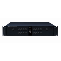
Центральный контроллер системы ECS-616 Inter-M является главным компонентом системы оповещения Inter-M 600-й серии.
Контроллер ECS-616 реализует следующие функции:
- Ручное и автоматическое управление системой оповещения.
- Подключение к централизованной системе оповещения ГО ЧС.
- Позоновое (16 зон +) оповещение непосредственно со стойки с помощью встроенного селектора (наивысший приоритет) или с удаленных микрофонных консолей RM-616.
- Организация системы громкой голосовой связи и оповещения с мини-АТС с использованием телефонного контроллера T-631.
- При использовании недельного таймера PW-642 возможна трансляция заранее записанных сообщений, сигналов или музыкальных и рекламных программ по расписанию.
- Приоритеты:
- Контроллер ECS-616 Inter-M при ручном аварийном оповещении имеет наивысший приоритет в системе (зоны трансляции выбираются непосредственно на контроллере). В автоматическом режиме работы при срабатывании станции пожарной сигнализации или при поступлении сигнала по фидерам централизованной системы оповещения ГО ЧС, контроллер прекращает любое неаварийное вещание во все зоны. Передаются только аварийные сигналы и сообщения.
- Вторым приоритетом в системе являются микрофонные панели RM-616 и телефонный контроллер T-631. Выбор зон трансляции производится на встроенном селекторе в микрофонных панелях или с помощью телефонного аппарата при использовании T-631. Сигналы от этих источников имеют более высокий приоритет перед музыкальной трансляцией и рекламным вещанием.
- Наименьшим приоритетом в системе являются источники фоновой музыки и иные сигналы, поступающие на систему через предварительный усилитель PP-613.
- Сигнал с усилителей мощности поступает непосредственно на контроллер ECS-616 Inter-M, к нему же подключаются трансляционные линии шлейфов громкоговорителей.
- Питание контроллера 24В DC производится с блока питания системы PD-659.
- Контроллер устанавливается в аппаратный шкаф или стойку 19″.
Характеристики
Технические характеристики Inter-M ECS-616:
| Зоны трансляции | 16 зон (++ каскадированием контроллеров) |
| Макс. коммутируемая мощность на зону | 500 Вт |
| Интерфейс для каскадирования ESC-616 | RS-232 |
| Расстояние RS-232 | 1200 м. |
| Питание | 24В DC |
| Потребляемая мощность | 21,6 Вт |
| Вес (кг) | 4,6 |
| Габариты | 482*88*380 мм |
Приоритеты оповещения с источников
| 1 | Ручное оповещение со стойки |
| 2 | Автоматическое по сигналам ОПС или ГО ЧС |
| 3 | Таймер |
| 4 | Удаленная микрофонная панель RM-616 1 |
| 5 | Удаленная микрофонная панель RM-616 2 |
| 6 | Музыкальные и другие источники подключенные к предусилителю |
Полезные файлы
Дополнительно

RM-6016 Inter-M Микрофонная панель на 16 зон
Селектор на 16 зон; однонаправленный конденсаторный микрофон на гибком держателе; линейный вход и выход; питание DC 24 В; 246х62х205 мм; 1.34 кг. Работает с контроллером ECS-616 или матричным коммутатором PX-9116.
Розница:45 927 руб.
Опт:39 936 руб.
Для дилеров:По запросу

RM-6800 Inter-M Универсальная микрофонная панель
Макс. 160 зон; конденсаторный микрофон на гибком держателе; линейный вход; инт. RS-422, макс. 1000 м; CAN, макс. 300 м; вх. «сухой контакт», 14 шт.; питание DC 24 В (DC 40 В при работе с NPX-8000); 200х73х206 мм; 1.29 кг. Работает с аудиоконтроллером NPX-8000, маршрутизатором тревожного оповещения PX-6116 и контроллерами PX-6216 / ECS-6216P.
Розница:87 547 руб.
Опт:76 128 руб.
Для дилеров:По запросу
Документация и программное обеспечение
Поиск документации для оборудования Inter-M и AFFA
Введите модель устройства, чтобы скачать руководство пользователя, руководство по ремонту
(англ.яз), схемы панелей и разъемов в .dwg формате, сертификаты (поиск осуществляется по актуальному
и архивному оборудованию)
Контроллер системы оповещения ECS-616 (архив)
Инструкции, схемы, регламенты к оборудованию
- Inter-M
- AFFA
© АРСТЕЛ, 1993 — 2023
Все права защищены
![]()
Наша компания всегда заботится о качестве производимых нами товаров и услуг. На протяжении всего времени, в течении которого существует компания, мы всегда выполняли свои обязательства перед клиентами.

Заказать систему
Спасибо за заказ. Наши менеджеры свяжутся с вами в ближайшее время
CONTACT US
г. Москва, 1-й Нагатинский проезд, д. 2
Телефон: +7 (499) 406-00-60
PGlmcmFtZSBzcmM9Imh0dHBzOi8vd3d3Lmdvb2dsZS5jb20vbWFwcy9lbWJlZD9wYj0hMW0xOCExbTEyITFtMyExZDIyNDkuMzg3NTA2MTMwOTE2ITJkMzcuNjMwODk3MjE1NjY5MzMhM2Q1NS42ODIyNTAzODA1MzQ1MDUhMm0zITFmMCEyZjAhM2YwITNtMiExaTEwMjQhMmk3NjghNGYxMy4xITNtMyExbTIhMXMweDQxNGFiMzU2NzFjNWJhNmYlM0EweDMxZjc1Y2RiZGU0YzI4OWMhMnpNUzNRdVNEUW5kQ3cwTFBRc05HQzBMalF2ZEdCMExyUXVOQzVJTkNfMFlBdDBMUXNJRElzSU5DYzBMN1JnZEM2MExMUXNDd2dNVEUzTVRBMSE1ZTAhM20yITFzcnUhMnNydSE0djE0OTk4MjAxOTU4NjEiIHdpZHRoPSI2MDAiIGhlaWdodD0iNDUwIiBmcmFtZWJvcmRlcj0iMCIgc3R5bGU9ImJvcmRlcjowIiBhbGxvd2Z1bGxzY3JlZW4+PC9pZnJhbWU+
Спасибо. Мы свяжемся с вами как можно скорее.