Контроллеры Eliwell линейки ID Next — это устройства нового поколения, подходящие для статических и вентилируемых установок при нормальных и низких температурах.
Линейка IDNext подходит для использования с установками, в которых используются легковоспламеняющиеся хладагенты, такие как R290 или R600.
Контроллеры ID Next имеет функцию глубокого цикла охлаждения (усовершенствованный алгоритм, позволяющий быстро снижать температуру). Функция Easy Map предлагает несколько предварительно загруженных конфигураций машины, а функция перегрева компрессора контролирует температуру нагнетания компрессора, уведомляя о любых плохих рабочих условиях.
Диапазон ID Next совместим с приложением Eliwell AIR и облачным решением TelevisAir.
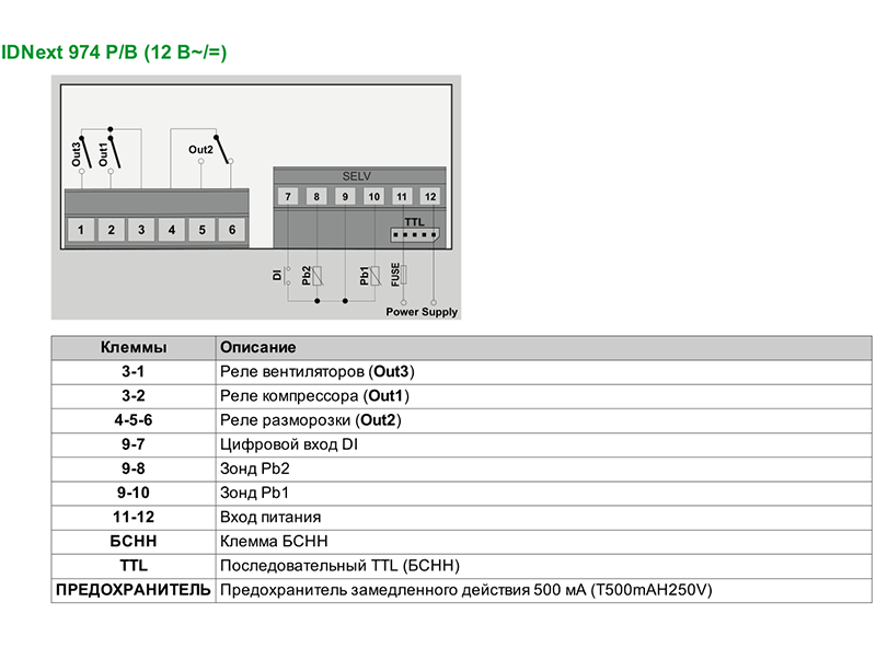
| Источник питания | 12 В переменного тока/постоянного тока |
| Потребляемая мощность | 5 ВА — 2,5 Вт |
| Диапазон отображения | -99,9…+99,9 °C -999…+999 °C |
| Аналоговые входы | 2 x PTC или NTC или Pt1000 |
| Цифровые входы | 1 x SELV |
| Цифровые выходы | 1 x SPST 2 л. с. 12(8)230 В переменного тока 1 x SPDT 0,5 л. с. 8(4)230 В переменного тока 1 x SPST 5(2)230 В переменного тока |
| Дисплей | Светодиодный индикатор 3 цифры + знак |
| Разрешение (0,1°C с десятичной запятой) | 0,1°C |
| Диапазон измерений | NTC: -50,0…+110,0 °C PTC: -55,0…+140,0 °C Pt1000: -55,0…+150,0 °C |
| Точность | NTC: лучше чем 0,5% от полной шкалы + 1 цифра РТС: лучше чем 0,5% от полной шкалы + 1 цифра Pt1000 в [-55,0…+70,0°С]: лучше чем 0,5% от полной шкалы + 1 цифра Pt1000 в [+70,0…+150,0°С]: лучше, чем 1% от полной шкалы + 1 цифра |
| Связь | Порт TTL для подключения к устройству мониторинга Unicard или TelevisSystemModBus |
| Последовательные порты | 1 x TTL |
| Установка | Панель, 71×29 мм |
| Аксессуары | USB-ключ Unicard/TTL BTLE/TTL |
| Вес нетто | 190 г |
| Ширина | 81 мм |
| Высота | 35 мм |
| Глубина | 60 мм |
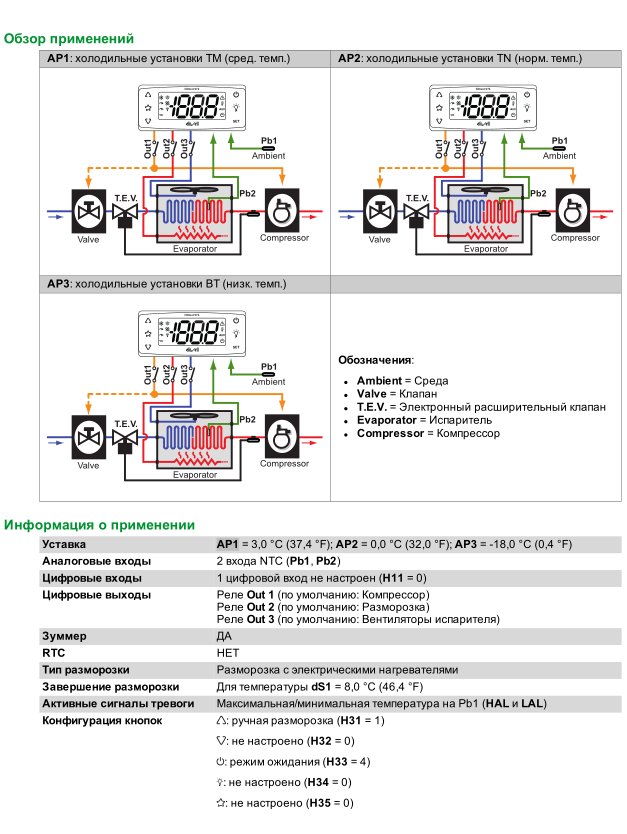
В каждом контроллере имеется 3 предопределенных приложения AP1, AP2, AP3 которые задают предварительную настройку контроллера для использования в 3-х реальных ситуациях, сокращая время, необходимое для установки, поскольку они требуют только изменения отдельных параметров.
Изменение рабочих параметров контроллера не влияет на значения предопределенных приложений. При первом включении прибора рабочие параметры такие же (в плане значений и видимости), как в приложении AP1.
Приложения AP1, AP2 и AP3 нельзя изменить с прибора. Приложения AP2 и AP3 могут быть изменены только с помощью Device Manager – программного обеспечения, разработанного Eliwell.
Приложение AP1 не может быть изменено никаким образом (даже с помощью Device Manager), чтобы позволить восстановить контроллер, используя приложение с гарантированной работоспособностью.
При первом пуске:
1. Выберите и загрузите предопределенное приложение AP1, AP2 или AP3 которое наилучшим образом подходит вашим рабочим потребностям.
2. Проверьте и при необходимости настройте значения основных параметров контроллера, чтобы привести выбранное приложение в соответствие с вашей системой.
3. Убедитесь в отсутствии активных сигналов тревоги.
USER INTERFACE
The user has a display and four keys for
controlling status and programming of the
instrument.
KEYS AND MENUS
UP key
Scrolls through the menu
items Increases the values
Activates manual def. function
DOWN key
Scrolls through the menu items
Decreases the values
Programmable by parameter
fnc key
ESC function (exit)
fnc
Programmable by parameter
set key
Accesses the setpoint
set
Accesses the menus
Confirms the commands
Displaying the alarms (if present)
At start-up the instrument performs a
Lamp Test; for few seconds the display and
the leds blink, in order to verify their inte-
grity and correct operation. The instru-
ment has two main menus: the «Machine
Status» and «Programming» menu.
ACCESSING AND USING MENUS
Resources are arranged in a menu, which
can be accessed by pressing and quickly
releasing the «set» key («Machine Status»
menu) or by holding down the «set» key
for more than 5 seconds («Programming»
menu).
To access the contents of each folder, indi-
cated by the relevant label, just press the
«set» key once.
You can now scroll through the contents
of each folder, modify it or use its func-
tions.
If you do not use the keyboard for over
15 seconds (time-out) or if you press the
«fnc» key once, the last value shown on
the display is confirmed and you return to
the previous screen mask.
LED
Position
Related Function
Compressor or relay 1
Defrost
Alarm
Fans
ID 974
electronic controllers for «forced air» refrigerating
units
MACHINE STATUS MENU
To access the «Machine Status» menu
Press and quickly release the «set» key.
If alarms are not present, the label «SEt»
appears. By using the «UP» and «DOWN»
keys you can scroll through the other fold-
ers in the menu:
-Pb1: probe 1 value folder;
-Pb2: probe 2 value folder
-SEt: Setpoint setting folder.
Set Setting
Access the «Machine Status» menu by
pressing and quickly releasing the «set»
key. The label of the «SEt» folder appears.
To display the Setpoint value press the
«set» key again.
The value appears on the display.
To change the Setpoint value, use the «UP»
and «DOWN» keys within 15 seconds.
If the parameter is LOC = y the Setpoint
cannot be changed.
Alarm on
If alarm condition exists, when accessing
The «Machine Status» menu the «AL» fold-
er label appears (see the «Diagnostics»
section).
Displaying Probes
By pressing the «set» key when the appro-
priate label appears, the value of the pro-
be associated to it is displayed.
PROGRAMMING MENU
To enter the «Programming» menu, press
the «set» key for more than 5 seconds.
If specified, the access PASSWORD will be
requested, (parameter «PA1»), and the
label of the first folder will follow.
To scroll through the other folders, use
the «UP» and «DOWN» keys.
To enter the folder, press «set». The label
of the first visible parameter appears. To
scroll through the other parameters, use
the «UP» and «DOWN» keys; to change the
parameter, press and release «set», then
set the desired value using the «UP» and
«DOWN» keys, and confirm with the «set»
key to move to the next parameter.
Status
ON when the compressor is started up; blinking in case of delay,
protection or blocked enabling
ON when defrosting; blinking in case of manual
enabling
ON when the alarm is enabled; blinking when the alarm is silenced
ON when the fan is working
PASSWORD
The password allows access to program-
ming parameters. In the standard configu-
ration password is not present.
To enable and assign it the desired value,
access the «Programming» menu, within
the folder with the «diS» label. If pass-
word is enabled, you will see it at the
entrance of the «Programming» menu.
MANUAL ACTIVATION OF THE
DEFROSTING CYCLE
To manually activate the defrosting cycle,
press the «UP» key for 5 seconds.
If defrosting conditions are not present,
(for example the evaporator probe
temperature is higher than defrost stop
temperature), the display
will blink three (3) times, in order to
indicate that the operation will not be
performed.
COPY CARD
The Copy Card is an accessory connected
to the TTL serial port which allows pro-
gramming quickly the instrument parame-
ters. The operation is performed as fol-
lows:
Format
This command allows copy card formatting,
an operation recommended in case of first
use.
Warning: if the copy card has been pro-
grammed, using the «Fr» the data entered
are erased. This operation cannot be can-
celled.
Upload
This operation loads the programming
parameters from the instrument.
Download
This operation downloads to the instru-
ment the programming parameters.
The operations are performed accessing
the folder identified by the «FPr» label and
selecting, according to the case, «UL», «dL»
or «Fr» commands; the operation is con-
firmed by pressing the «set» key. If the
operation is successful an «y» is displayed,
on the contrary, if it fails a «n» will be dis-
played.
Tab. 1
Parameter Table
DESCRIPTION
PAR.
COMPRESSOR REGULATOR (folder with «CP» label)
diFferential. Relay compressor tripping differential. The compressor stops on reaching the
diF
Setpoint value (as indicated by the adjustment probe), and restarts at temperature value
equal to the Setpoint plus the value of the differential.
Note: the value 0 cannot be assumed.
Higher SEt. Maximum possible setpoint value.
HSE
Lower SEt. Minimum possible setpoint value.
LSE
COMPRESSOR PROTECTIVE DEVICE (folder with «CP» label)
On time (compressor). Compressor activation time in the event of faulty probe. If set to
Ont
«1» with Oft at «0» the compressor is always on, while at Oft >0 it functions always
in duty cycle mode.
OFF time (compressor). Compressor in disabled state time in the event of a faulty probe.
OFt
If set to «1» with Ont at «0» the compressor is always off, while at Ont >0
it functions always in duty cycle mode.
delay (at) On compressor. Delay time in activating the compressor relay after switch-on
dOn
of instrument
delay (after power) OFF. Delay after switch off; the indicated time must elapse between
dOF
switch-off of the compressor relay and the successive switch-on.
delay between power-on. Delay between switch-ons; the indicated time must elapse
dbi
between two successive switch-ons of the compressor.
delay Output (from power) On. Delay time in activating the outputs after switch-on of
OdO
the instrument or after a power failure.
DEFROSTING REGULATOR (folder with «dEF» label)
defrost type. Type of defrosting.
dty
0 = electric defrost;
1 = reverse cycle defrost (hot gas);
2 = Free defrost (compressor hot).
defrost interval time. Interval between the start of two successive defrosting operations.
dit
dCt
defrost Counting type. Selection of count mode for the defrosting interval.
0 = compressor operating hours (DIGIFROST® method);
1 = Real Time – appliance operating time;
2 = compressor stop.
defrost Offset Hour. Start-of-defrosting delay time from start up
dOH
of instrument.
defrost Endurance time. Defrosting time-out; determines duration of
dEt
defrosting.
defrost Stop temperature. Defrost stop temperature (defined by the evaporator
dSt
probe).
defrost (at) Power On. Determines if at the start-up the instrument must enter defrosting
dPO
(if the temperature measured by the evaporator allows this operation).
y = si; n = no.
FANS REGULATOR (folder with «FAn» label)
Fan Stop temperature. Fan lock temperature; if the value, read by the evaporator probe,
FSt
is higher than the set value, fans stop.
Fan differential. Fan starting differential (see par. «FSt» and «Fot»).
FAd
Fan delay time. Delay time in activating fans after a defrost operation.
Fdt
drainage time. Dripping time.
dt
defrost Fan disable. Allows to select the evaporator probes exclusion
dFd
during defrost. y = yes; n = no.
Fan Compressor OFF. Allows to select compressor fans lock
FCO
OFF (switched off).
y = fans activated (with thermostat; based on the value read by the defrost probe,
see parameter «FSt»);
n = fans off;
d.c. = duty cycle (by parameters «Fon» and «FoF»).
ALARMS (folder with «AL» label)
Alarm Fan differential. Alarm differential.
AFd
Higher ALarm. Maximum temperature alarm. Temperature value (with regard to Setpoint)
HAL
which if exceeded in an upward direction triggers the activation of the alarm signal.
Lower ALarm. Minimum temperature alarm. Temperature value (with regard to Setpoint),
LAL
which if exceeded in a downward direction, triggers the activation of the alarm signal.
Power-on Alarm Override. Alarm exclusion time after instrument switch on,
PAO
after a power failure.
defrost Alarm Override. Alarm exclusion time after defrost.
dAO
temperature Alarm Override. Temperature alarm signal delay time.
tAO
DISPLAY (folder with «diS» label)
(keyboard) LOCk. Keyboard locking. However, you can enter parameter programming
LOC
modify them along with the status of this parameter in order to allow keyboard locking.
y = yes; n = no
PAssword 1. When enabled (value other than 0) it constitutes the access key for
PA1
level 1 parameters.
ndt
number display type. View with decimal point. y = yes; n = no
CAlibration 1.Calibration 1. Positive or negative temperature value added to the value
CA1
read by probe 1, based on «CA» parameter settings.
CAlibration 2.Calibration 2. Positive or negative temperature value added to the value
CA2
read by probe 1, based on «CA» parameter settings.
defrost display Lock. Modalità di visualizzazione durante lo sbrinamento.
ddL
0 = visualizza la temperatura letta dalla sonda cella;
1 = blocca la lettura sul valore di temperatura letto dalla sonda cella all’istante di entra-
ta in sbrinamento e fino al successivo raggiungimento del valore di Setpoint;
2 = visualizza la label «deF» durante lo sbrinamento e fino al successivo raggiungimento
del valore di Setpoint.
dro
display read-out. Selezione °C o °F per la visualizzazione temperatura letta dalla sonda.
0 = °C, 1 = °F.
ID 974 LX
RANGE
DEFAULT
VALUE*
0.1…30.0
2.0
LSE..302
99.0
-55.0…HSE
-50.0
0…250
0
0…250
1
0…250
0
0…250
0
0…250
0
0…250
0
0/1/2
0
0…250
6
0/1/2
1
0…59
0
1…250
30
-50.0… 150
8.0
n/y
n
-50.0..150.0
2.0
1.0…50.0
2.0
0…250
0
0…250
0
n/y
y
n/y/d.c.
y
1.0…50.0
2.0
LAL…150.0
50.0
-50.0…HAL
-50.0
0…10
0
0..999
0
0…250
0
n/y
n
0…250
0
n/y
y
-12.0…12.0
0
-12.0…12.0
0
0/1/2
1
0/1
0
LEVEL**
U.M.
1
°C/°F
1
°C/°F
1
°C/°F
1
min
1
min
1
sec
1
min
1
min
1
min
1
flag
1
hours
1
flag
1
min
1
min
1
°C/°F
1
flag
1
°C/°F
1
°C/°F
1
min
1
min
1
flag
1
flag
1
°C/°F
1
°C/°F
1
°C/°F
1
hours
1
min
1
min
1
flag
1
number
1
flag
1
°C/°F
1
°C/°F
1
flag
1
flag
3/4