-
Contents
-
Table of Contents
-
Bookmarks
Quick Links
User Guide
Smartpack S Controller
Monitoring and Control Units
Flatpack S DC Power Supply Systems
350030.013
Related Manuals for Eltek Smartpack S
Summary of Contents for Eltek Smartpack S
-
Page 1
User Guide Smartpack S Controller Monitoring and Control Units Flatpack S DC Power Supply Systems 350030.013… -
Page 2
Always tighten screws and bolts with the torque values recommended in the documentation. For safety reasons, the commissioning and confi guration of the equipment is only to be performed by Eltek’s personnel or by author-… -
Page 3
— for any purpose without the explicit written permission of Eltek. Copyright ©: Eltek, 2012 Eltek’s Part Number: 242100.410 Smartpack S Controller Doc No: 350030.013 Issue 1.0, 2012 Jun Published 2012-07-05 mafeno User Guide • Smartpack S Controller… -
Page 4: Table Of Contents
Table of Contents 1. Introduction ………………5 About this Guide………………….. 5 System Diagram — Flatpack S Power System …………5 2. The Smartpack S Controller …………6 Key Features ……………………6 Installing Smartpack S Controllers …………….7 Removing Smartpack S Controllers ………………7 Mounting Smartpack S Controllers ………………7…
-
Page 5: Introduction
Introduction 1. Introduction The advanced Smartpack S controllers are developed for Eltek’s Flatpack S sys- tem platform, suitable for small and medium telecom and industrial DC power sys- tems. About this Guide This booklet provides users of Smartpack S-based DC power systems with the re- quired information for operating the system using the Smartpack S’s front panel.
-
Page 6: The Smartpack S Controller
◊ Uploading and downloading of firmware and configuration files via PC ◊ Buzzer for audio indication of alarm conditions and key pressure feedback Read also chapter “Technical Specifications” on page 16, for more details. User Guide • Smartpack S Controller…
-
Page 7: Installing Smartpack S Controllers
Blind panel’s handle position • To remove a blind panel Removing: Push down and push the panel’s handle downwards and pull out to release Insert pull out to release the panel User Guide • Smartpack S Controller…
-
Page 8: Accessing The Controller’s Ethernet Port
The Ethernet port can also be accessed from the power system’s rear, for more permanent connections of the system to a LAN. A dedicated Ethernet cable may be ordered from Eltek, when the rear cable entry to the controller becomes too tight.
-
Page 9: Location Of Connector, Communication Ports
Ground Figure 2. Location of pluggable terminal blocks, RS232/RS485 port and Ethernet connector in the Smartpack S controller (the pluggable terminals may be black or green) All the controller’s system connections to the system’s backplane are implement- ed via an edge connector, when inserting the controller in the power system.
-
Page 10: Connection Drawing
(Via edge connector to the system’s backplane) Figure 3. Connection Drawing for Smartpack S controller The configurable inputs 1 through 4 operate in the range of max. – 10 to +10VDC, and are intended for great accurate measurements, e.g. for temperature sensing using an external temperature NTC probe.
-
Page 11: Can Bus Termination
Figure 4. Example of CAN bus addressing and termination in a Flatpack S power sys- tem with Smartpack S-based control system and some CAN nodes connected the CAN bus When connecting more CAN nodes to the bus, you have to remove the CAN bus termination plug from one of the CAN bus ends, and plug it in one of the CAN ports on the last connected CAN node.
-
Page 12: Configuration
The controller’s ID # corresponds to the DIP switch’s binary value plus 1 ** The DIP switch positions above applies to all controllers, except for Smartpack2 Master and Compack controllers, which have unchangeable ID# 11 and 1 respectively Table 1. Smartpack S controller’s DIP switch addressing User Guide • Smartpack S Controller…
-
Page 13: Front Panel Operation
ON red Alarm (Major alarm, Critical Alarm) Table 2. Description of the Smartpack S controller’s LED illumination status Front Keys You can operate the power system navigating intuitively through the graphical menu structure via the following 4 front keys. We recommend using a pen or similar tool to press the keys, as they are small.
-
Page 14: Software Menus
(Level 3) Example Submenu “Monitors Statistics” (Level 3) From a PC’s web browser, via WebPower, or running the PowerSuite program, you can also access the complete system functionality, described in the programs’ On- line Help. User Guide • Smartpack S Controller…
-
Page 15: Controller Access — Via Stand-Alone Pc
You can access the Smartpack S controller directly from a stand-alone computer, or via a Local Area Network (LAN) if available. Each controller is shipped with a unique Eltek MAC address stored inside the con- troller and marked on the controller’s label, and with the fixed IP address <192.168.10.20>.
-
Page 16: Technical Specifications
ETSI EN 300 019: 2-1 (Class 1.2), 2-2 (Class 2.3) & 2-3 (Class 3.2) ROHS compliant *) As part of CA0603.000 Flatpack S 3U Marine system Specifications are subject to change without notice Doc 242100.410.DS3 – v1 User Guide • Smartpack S Controller…
-
Page 17: Firmware Upgrade Controller
Firmware Upgrade Controller Upgrade of the Smartpack S controller’s firmware, while the system is live, is per- formed via the controller’s Ethernet port, using the “Eltek Network Utility” program (EVIPSetup.exe) to transfer the firmware file to the controller. Upgrading the firmware does not delete or change any of the configuration and calibration values stored in the controllers.
-
Page 18: Overview Lan Devices And Firmware Files (Pc — S19 Format)
The Smartpack S Controller Overview LAN Devices and Firmware Files (PC — S19 Format) The “Eltek Network Utility” program <EVIPSetup.exe> will transfer the specific firmware file (s19-format) from a LAN connected computer to the device (or hard- ware platform). LAN Device…
-
Page 19: About Power System Configuration
About Power System Configuration 3. About Power System Configuration The Eltek DC power supply system’s functionality represents a vast set of func- tions, characteristics or capabilities implemented in the hardware and software of the controllers, control units and nodes connected to the system’s CAN bus.
-
Page 20: System Status Options
The default Service Access Level password or Pin-Code is <0003>. We strongly recommend changing the passwords as soon as the power system is installed. The available Alarm Monitors are organized in system-oriented groups: Mains, Gen- erator, Rectifier, Load, etc. User Guide • Smartpack S Controller…
-
Page 21: Commands Options
The commands are organized in following groups: • System Commands • Battery Commands • Outputs Test Read about «Output Test Commands» on page User Guide • Smartpack S Controller…
-
Page 22: Logs And Reports Options
Battery Test Log The Battery Test Log is displayed in a results table; each row of data represents a battery test. Also, the battery quality, calculated by completed battery tests, and other test parameters are displayed. User Guide • Smartpack S Controller…
-
Page 23: Statistics Options
This logical group presents a generic description of the steps required to carry out commissioning tasks of the power system. Refer also to the system’s user documentation, and to the Commissioning Proce- dure pull-out list in the system’s quick start guide. User Guide • Smartpack S Controller…
-
Page 24: Up/Download Options (Data Storage Device)
Also, you can upload a similar, specific System Configuration file <UNIT_nn.HEX> to the controller or to any connected CAN unit, e.g. for automatic configuration of specific functions The “nn” in the file name specifies the unit’s CAN bus address. User Guide • Smartpack S Controller…
-
Page 25: Sd Card Storage — Overview Firmware Files (Binary Format)
Any node UNIT_aa.HEX Configuration File (Save/Load) All types The “aa” refers to the CAN bus address or ID number. E.g. “UNIT_82.HEX” could be the configuration file for I/O Monitor with CAN bus address 82. User Guide • Smartpack S Controller…
-
Page 26: Flash Memory Storage
It is not recommended to use the FTP client embedded in Windows Explorer. WARNING: Before uploading files to the Flash memory (4MB), check that there is enough storage space. Also, consider deleting files that are no longer necessary. User Guide • Smartpack S Controller…
-
Page 27: Alarm Monitors
You have to Enable the alarm monitor so that it functions • Type of alarm reset You can select whether the alarm generated by monitor can be reset manually, or automatically (when the event that caused the alarm is no longer true) User Guide • Smartpack S Controller…
-
Page 28
The alarm monitor stores all input signal measurements and performs average calculations every minute. Then, the monitor continuously displays the input signal average value, and the period of time the input signal has been measured. You can restart the monitor’s average calcu- lations. User Guide • Smartpack S Controller… -
Page 29: Types Of Alarm Monitors
The power system’s controller uses following types of alarm monitors, determined by the monitor’s type of input signal: • Logical Alarm Monitors (L1) • Numeric Alarm Monitors (N1, N2%) • Analogue Alarm Monitors (A2, A4) • Special Alarm Monitors (LVD) User Guide • Smartpack S Controller…
-
Page 30
Selects among delay time options (b) MajorHigh AlarmLevel Upper limit MajorHigh AlarmGroup Major Alarm Selects the alarm group to activate MinorHigh AlarmLevel Lower limit MinorHigh AlarmGroup Minor Alarm Selects the alarm group to activate User Guide • Smartpack S Controller… -
Page 31
Selects the alarm group to activate Major Low lower limit Selects the alarm group to activate The LVD alarm monitors “observe” that the battery voltage (input signal) is within limits, otherwise they activate the LVD contactors (alarm group). User Guide • Smartpack S Controller… -
Page 32
Delay Time after Disconnect Enter the Time delay or number of seconds the LVD contactor has to be tripped or disconnected, before the alarm monitor is allowed to reconnect the LVD contactor User Guide • Smartpack S Controller… -
Page 33: Alarm Output Groups
The outputs of Smartnode control units are telephone numbers, instead of relay outputs. The assignment procedure is the same, but you group the phone numbers and assign them to Alarm Output Group. Read also topic “Control Unit Modem Callback Setup tab” in PowerSuite Help. User Guide • Smartpack S Controller…
-
Page 34
“OutpBlocked, AOG” group, e.g. to activate a lamp or alarm bell when the alarm output relays are blocked. Read more in topic «Alarm Outputs Isolation (Output Blocked)» on page • Alarm Groups 9 through 17 are unused, and can be assigned when re- quired User Guide • Smartpack S Controller… -
Page 35: Output Test Commands
NOT trigger any alarm output groups (output relays activation is blocked), except for AOG 18. Also, this command will always activate Alarm Output Group 18 to facilitate external warning of this function being active. User Guide • Smartpack S Controller…
-
Page 36
Headquarters: Eltek Visitor address: Gråterudveien 8, 3036 Drammen, Norway Phone: +47 32 20 32 00 Fax: +47 32 20 32 10…

2
Содержание
Введение
…………………………………………………………………………………. 4
Поздравляем… ………………………………………………………………… 4
Пользование данным руководством …………………………………. 4
Общий обзор
……………………………………………………………………………. 5
Характеристики приборов ……………………………………………….. 5
Настенный блок SmartPack Wall Mount ……………………………. 6
Переносной блок SmartPack 19” Portable………………………….. 8
Туровая система SmartPack Touring System ………………………. 9
Глава
1 Меню и конфигурация
…………………………………………………………….. 10
Пользовательский интерфейс ……………………………………………. 10
Сетевой переключатель и LED-индикаторы ………………….. 10
Панель управления ………………………………………………………. 10
LCD-дисплей ……………………………………………………………….. 11
Начальные установки на дисплее …………………………………… 11
Блокировка Меню …………………………………………………………. 11
Структура меню Normal …………………………………………………….. 12
Меню Normal ………………………………………………………………… 12
Meню тестирования ………………………………………………………. 12
Структура расширенного меню (Advanced ) ………………………… 13
DMX …………………………………………………………………………… 14
Пресеты ……………………………………………………………………….. 14
Секвенсер …………………………………………………………………….. 15
Диммерные кривые ………………………………………………………. 16
Аварийный режим ………………………………………………………… 17
Станции управления SmartLink …………………………………….. 17
Общие настройки (General Settings) ………………………………. 19
Диагностика …………………………………………………………………. 20
Глава
2 Подключение SmartLink
™
………………………………………………………… 20
Функции ……………………………………………………………………….. 20
Определения …………………………………………………………………. 21
Синхронизация модулей ……………………………………………………. 22
Синхронизация пресета и секвенции ………………………………. 23
Настенные кнопочные станции (Wall Stations) ……………………. 25
Настройки кнопочных станций ……………………………………… 26
Запись пресета с кнопочной станции ………………………………….. 28
Глава
3
Обслуживание
и сервис
………………………………………………………. 29
Сервис ……………………………………………………………………………… 29
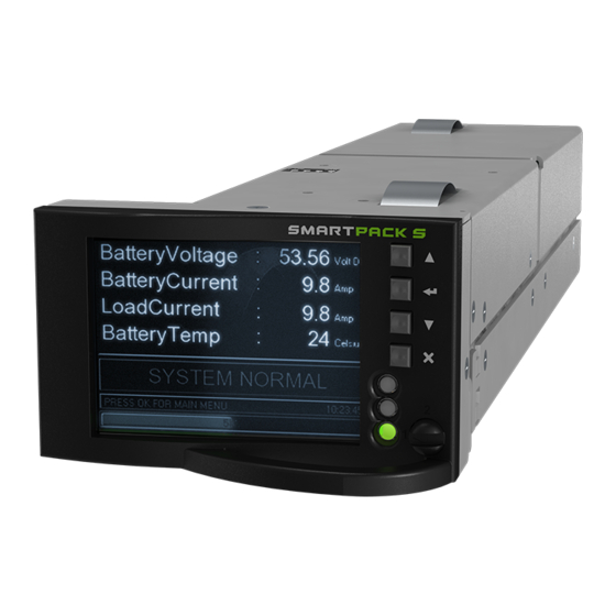
Компактный, многофункциональный, универсальный контроллер с возможностью горячей замены.
Разработанный для системной платформы Flatpack S, Smartpack S находит свое применение во многих приложениях с ограниченным пространством. Используемый в силовых стойках высотой 1U и глубиной 265 мм, Smartpack S обеспечивает всесторонний мониторинг и управление системой мощностью 2-3 кВт, занимающей менее 6 литров.
Ключевые функции
- Графический 2,2-дюймовый цветной tft-дисплей с высокой контрастностью и высоким разрешением для удобной навигации в пользовательском меню
- Ethernet для удаленного или локального мониторинга и управления через веб-браузер
- Протокол SNMP с ловушкой, установкой и получением по ethernet. электронная почта сигналов тревоги о ловушках
- 6 программируемых релейных выходов
- 6 программируемых многоцелевых входов (“цифровые входы” или аналоговые сигналы).
- Комплексное ведение журнала
- Автоматический контроль и тестирование батареи
- Качество батареи SoH на основе результатов тестирования и многое другое
Ввод
Напряжение постоянного тока (рабочий диапазон)
10 — 75 В постоянного тока
Электрический
Потребляемая мощность
3,1 Вт
НАРАБОТКА НА ОТКАЗ
900000 ч
Выход
Выход
Форма-C
Сухой контакт (NO-C-NC)
Макс 75 В
Настраиваемые входные данные
Количество настраиваемых входов
6
Цифровые конфигурации
#1-6: Открыто/закрыто
Количество аналоговых конфигураций
6
Аналоговые конфигурации
#1-4:
Температура: датчик NTC
Аналог:+/-0- 10В
Измерение тока 4-20 мА
Порты
Доступные порты
Ethernet; RS-282; RS-485
Дисплей
Разрешение
QVGA 32k цветной TFT
Другой
Рабочая температура
-20 — 65 °C
Температура хранения
-40 — 70 °C
Размеры
Размеры ШхВхГ (мм)
72,2 x 43 x 220,7 мм
Размеры ШхВхГ (дюйм)
2,8 x 1,7 x 8,7 «
Сертификаты
Морской
DNV 2.4 Действителен для детали № 242100.410M
Функциональность программного обеспечения
Удаленный Мониторинг
DHCP
DHCPv6
SNMP v1, v2c и v3
Ведомое устройство MODBUS TCP/RTU
Обратный вызов модема и SMS-сигнализация для GSM-модемов
IPv4
IPv6 (статическая ссылка)
IPv6 (автоконфигурация без сохранения состояния)
IPv6 (автоконфигурация с полным состоянием) — DHCPv6
SNTP — синхронизация часов
Пользовательские отчеты SMTP/email в формате .csv прилагаются
SMTP Безопасный
РАДИУС (единый вход)
FTP — передача файлов (обновления SW, загрузка журналов и т.д.)
FTPS — защищенный FTP
UDP PComm для PowerSuite (Средство настройки/мониторинга Windows)
HTTP (Веб-страницы со всеми функциями / функциями / мониторингом — адаптивный дизайн для экрана ПК, планшета, смартфона)
HTTPS (зашифрованный веб-интерфейс TLS)
Функции/Контроль выпрямителя
Менеджер по эффективности
ОН Приоритетный
Медленное / быстрое / Литий-ионное повышение напряжения
Увеличение Мощности
Регулируемый Предел тока
Обзор запасов
Автоадресация/подключи и играй
Мануэль адессинг переопределение
Динамический выходной OVS
Задержка запуска
Контроль тока выпрямителя (2-уровневая сигнализация)
Контроль ошибок выпрямителя (2-уровневый сигнал тревоги)
Мониторинг ошибок связи выпрямителя (2-уровневый сигнал тревоги)
Контроль использования выпрямителя (2-уровневая сигнализация)
Использование выпрямителя BT Мониторинг спецификации (2-уровневая сигнализация)
Мониторинг ошибок Распределения тока выпрямителя (2-уровневый сигнал тревоги)
Наивысший Контроль температуры воздуха На Входе выпрямителя (2-уровневая сигнализация)
Кол-во выпрямителей с низким напряжением сети (2-уровневая сигнализация)
Функции/Мониторинг выпрямителя
Регулируемая выходная частота
Регулируемое выходное напряжение переменного тока
Регулируемый диапазон удержания частоты / гистерезис для инверторного режима
Регулируемый Предел постоянного Тока
Обзор запасов
Автоадресация/подключи и играй
Мануэль адессинг переопределяет
Динамический выходной OVS
Контроль выходного напряжения переменного тока выпрямителя Фазы 1, 2 и 3 (4-уровневая сигнализация)
Контроль выходной частоты переменного тока выпрямителя (4-уровневая сигнализация)
Контроль выходного тока выпрямителя переменного тока Фазы 1, 2 и 3 (2-уровневая сигнализация)
Общий контроль Выходного тока постоянного тока выпрямителя (2-уровневая сигнализация)
Мониторинг ошибок выпрямителя (2-уровневый сигнал тревоги)
Мониторинг Фазы 1, 2 и 3 Ошибки распределения переменного тока выпрямителя (2-уровневая сигнализация)
Контроль мощности переменного тока выпрямителя (2-уровневая сигнализация)
Контроль мощности постоянного тока выпрямителя (2-уровневая сигнализация)
Температура выпрямителя (4-уровневый сигнал тревоги)
Мониторинг ошибок связи с выпрямителем (2-уровневый сигнал тревоги)
Управление/Мониторинг батареи
Температурная компенсация
Симметрия — Измерение средней точки 12В, 24В, 30В, 36В
Измерение симметрии — Блок 6В, 12В, 24В
Автоматический Заряд Наддува
Интервальный Заряд Наддува
Последующий заряд наддува
Выравнивание заряда, ручное и автоматическое
Температурная компенсация во время наддува и выравнивания заряда
Проверка работоспособности батареи при разряде (SoH) — нормальная, основана на разряде batt. Спекуляция.
Тестирование работоспособности разряда батареи (SoH) — простое, основанное на требованиях времени резервного копирования.
Проверка работоспособности разряда батареи (SoH) — ручная, интервальная или альтернативная схема
Протоколирование тестов батареи
Протоколирование цикла DoD батареи
Регистрация счетчика циклов заряда батареи
Регистрация времени работы от батареи
Прогнозирование срока службы батареи на основе диапазонов температур
Проверка разряда батареи — простая или расширенная (на основе шунта в каждой строке)
Аналоговое регулирование плавающего заряда аккумулятора на основе входного сигнала напряжения
Контроль напряжения батареи (4-уровневая сигнализация)
Контроль тока батареи (4-уровневая сигнализация)
Самый высокий из нескольких режимов контроля температуры батареи (4-уровневый сигнал тревоги)
Индивидуальная температура батареи (4-уровневый сигнал тревоги)
Контроль SoC батареи (2-уровневый сигнал тревоги), % или Ач
Контроль заряда/разряда накопленных Ач (2-уровневая сигнализация)
Сбой Контроля тестирования батареи (1-уровневый сигнал тревоги)
Индивидуальный контроль предохранителя батареи (1-уровневая сигнализация)
Индивидуальный контроль тока аккумуляторной Батареи (2-уровневая сигнализация)
Связь FIAMM SONICK Battery BMS
SAFT Evolion Battery BMS связь
Связь Narada Battery BMS
Связь Leoch Battery BMS
Батарея Священного Солнца Батарея BMS Связь BMS
Связь с батареей Northstar ACE (шлюз)
Протокол связи с универсальной батареей Eltek
LVBD (напряжение, температура, управляемая сеть)
Мониторинг сети/Сети
Контроль фазового сбоя (2-уровневая сигнализация)
Контроль фазного напряжения (4-уровневая сигнализация)
Контроль частоты (2-уровневая сигнализация)*
Активное/Реактивное/Различное Регулирование мощности 3 фазы (2-уровневые сигналы тревоги)*
Контроль коэффициента мощности 3 фазы (2-уровневая сигнализация)*
Контроль сетевого тока 3 фазы (2-уровневая сигнализация)*
*Требуется подключение CAN-узла монитора сети переменного тока или Smartmeter
Управление нагрузкой/Мониторинг
LVLD
Coldstart LVLD
Контроль предохранителей нагрузки (1-уровневая сигнализация)
Контроль тока нагрузки (2-уровневая сигнализация)
Индивидуальный контроль предохранителей нагрузки (1-уровневая сигнализация)
Индивидуальный контроль тока Нагрузки (2-уровневая сигнализация)
Индивидуальный Контроль Мощности Нагрузки
Регистрация энергии индивидуальной нагрузки
Ведение журнала затрат энергии на индивидуальную нагрузку
Программируемая логика
ИЛИ функция нескольких сигналов тревоги /событий
И функция нескольких сигналов тревоги / событий
Инверсия логических сигналов
Планировщик задач (ежечасно, ежедневно, еженедельно, ежемесячно) любых команд/событий
Группировка сигналов тревоги
Доступные журналы
Регистрация энергии (сеть, выпрямитель, преобразователь, аккумулятор, нагрузка) — ежечасно, ежедневно, еженедельно
Регистрация данных (10 параметров, различные интервалы срабатывания и триггеры событий)
BHL/HAA-loggs
Журнал входа в учетную запись
Журнал изменений
Экспорт инвентаря
Климат-контроль и Мониторинг
Управление вентилятором, линейная скорость в зависимости от температуры / максимальной скорости
Контроль Отклонения Скорости Вращения Вентилятора
Снижение влажности
Промежуточный Предварительный тест
Различные Контроллеры
Настройка безопасности (открытие/закрытие портов UDP/TCP)
Настройка учетной записи пользователя
Программируемый Звуковой сигнал
Удаленное обновление программного обеспечения — главный контроллер по IP
Удаленное обновление программного обеспечения — Узлы CAN через maincontroler по FTP
Светодиодный Тест контроллера/Модуля Питания
Программируемые Виртуальные Входы
Конфигурации XML — полная гибкость параметров
Конфигурации XML — массовое распространение, Загрузка веб-интерфейса, Загрузка Windows, Загрузка с SD-карты / FTP
The product warranty becomes invalid if the following safety precautions are not followed during handling,
installation, commissioning and general use/operation of Eltek DC power supply system.
General Precautions
!
CAUTION: Even though the product incorporates protection circuitry and other safeguards, it can be damaged, perform poorly or
have a reduced lifetime if it is exposed to incorrect treatment during transport, installation or service. Always handle the equip-
ment using proper lifting techniques, do not roll, climb or drill hole in the cabinets or enclosures.
Device
Hazard
WARNING: Opening the equipment may cause terminal injury — even if the mains AC supply is disconnected. Hazardous voltages
may be present inside, as large capacitors may still be charged.
Electric
Shock
Environmental Precautions
CAUTION: To avoid damage the equipment, keep objects clear of system ventilation inlets, outlets and system fans, if any, ensur-
sss
ing the airfl ow through the units is not obstructed, and that the fans rotate freely. Use caution with rectifi ers, as they can reach
extreme temperatures under load and normal operation.
Ventilated
Hot Surface
WARNING: The installer/user is responsible for ensuring that the DC power system is not damaged by current surges, over-
voltages, etc. caused by external transients, lightning, electrostatic discharge, etc. To avoid damage and obtain the expected
system reliability, it is mandatory to always install SPDs in Eltek’s power supply systems. Follow the instructions given in
Current Surge
Protection
«Guidelines for Lightning and Surge Protection», doc. 2024623.
WARNING: The electronics in the power supply system are designed for indoor, clean environment. When installed in outdoor en-
closures, it is important to keep the door closed during operation, and replace the fi lters on a regular basis. Indoor installations
in dusty or humid areas require appropriate air fi ltering of the room, or fi ltering of the air entering the DC power system. Follow
Humidity & Dust
Protection
the instructions given in «Generic Guidelines Environmental Protection.», doc. 2038879
Precautions during Installation
!
CAUTION: Read the user documentation carefully before installing and using the equipment, as installation and operation is to
be performed as described in it. Always tighten screws and bolts with the torque values recommended in the documentation. For
safety reasons, the commissioning and confi guration of the equipment is only to be performed by Eltek’s personnel or by author-
Qualifi ed
Personnel
ized and qualifi ed persons.
!
CAUTION: The installer is responsible for ensuring that the EMC properties of this product/ system do not deteriorate during in-
stallation, and that it is performed in accordance with applying regulations.
EMC, NEC/CEC
Installations in USA and Canada must comply with NEC/CEC requirements.
Regard
!
CAUTION: Before you start the electrical installation, you must always disconnect all external AC supply fuses, as well as internal
battery and load fuses/ breakers, if any.
Device
Hazard
WARNING: For safety reasons (high leakage current / high touch current) you must always connect the AC earth wire (PE) to the
terminals, before you connect the AC input cable(s).
Electric
The batteries, if any, represent a major energy hazard. To avoid short-circuit of battery poles, you must always remove metallic
Shock
objects — uninsulated tools, rings, watches, etc. — from the vicinity of the batteries.
WARNING: 60V DC power systems are only to be installed in Restricted Access Locations (RAL). Access must be limited by use
of tool, i.e. lock and key.
Electric
Shock
2
SAFETY and ENVIRONMENTAL PRECAUTIONS
User Guide • Smartpack S Controller
DC Power Supply Systems
G1
G2
E1
E2
E3
I1
I2
I3
I4
I5
2
Содержание
Введение
…………………………………………………………………………………. 4
Поздравляем… ………………………………………………………………… 4
Пользование данным руководством …………………………………. 4
Общий обзор
……………………………………………………………………………. 5
Характеристики приборов ……………………………………………….. 5
Настенный блок SmartPack Wall Mount ……………………………. 6
Переносной блок SmartPack 19” Portable………………………….. 8
Туровая система SmartPack Touring System ………………………. 9
Глава
1 Меню и конфигурация
…………………………………………………………….. 10
Пользовательский интерфейс ……………………………………………. 10
Сетевой переключатель и LED-индикаторы ………………….. 10
Панель управления ………………………………………………………. 10
LCD-дисплей ……………………………………………………………….. 11
Начальные установки на дисплее …………………………………… 11
Блокировка Меню …………………………………………………………. 11
Структура меню Normal …………………………………………………….. 12
Меню Normal ………………………………………………………………… 12
Meню тестирования ………………………………………………………. 12
Структура расширенного меню (Advanced ) ………………………… 13
DMX …………………………………………………………………………… 14
Пресеты ……………………………………………………………………….. 14
Секвенсер …………………………………………………………………….. 15
Диммерные кривые ………………………………………………………. 16
Аварийный режим ………………………………………………………… 17
Станции управления SmartLink …………………………………….. 17
Общие настройки (General Settings) ………………………………. 19
Диагностика …………………………………………………………………. 20
Глава
2 Подключение SmartLink
™
………………………………………………………… 20
Функции ……………………………………………………………………….. 20
Определения …………………………………………………………………. 21
Синхронизация модулей ……………………………………………………. 22
Синхронизация пресета и секвенции ………………………………. 23
Настенные кнопочные станции (Wall Stations) ……………………. 25
Настройки кнопочных станций ……………………………………… 26
Запись пресета с кнопочной станции ………………………………….. 28
Глава
3
Обслуживание
и сервис
………………………………………………………. 29
Сервис ……………………………………………………………………………… 29
-
350030.013
Flatpack S DC.
Smartpack S
-
! «» Heading 1 , . ! «» Heading 1 , .
2 Smartpack S Controller 350030.013, Issue 1.0, 2012 Jun
DC Power Supply Systems
, , , Eltek.
: , , , , . —
, , .
: , —
. — .
Device Hazard
!
Electric Shock
G1
G2
: , , —
. , .. .
: , ., —
, , . —
Eltek
Guidelines for Lightning and Surge Protection, doc. 2024623.
: —
. —
. —
, . —
, Generic Guidelines Environmental Protection., doc.
2038879.Ventilated Hot Surface
Humidity & Dust Protection
Current Surge Protection
E2
E1
E3
: , ,
, —
.
: —
, .. .
. —
Eltek, , .
: ,
/ .
: —
( ).
. —
, , ..
: 60
, .
Device Hazard
!
Qualified Personnel
!
EMC, NEC/CEC Regard
!
Electric Shock
Electric Shock
I1
I2
I3
I4
I5
-
! «» Heading 1 , . !
«» Heading 1 , .
Smartpack S Controller 350030.013, Issue 1.0, 2012 Jun 3
Eltek.
—
—
,
Eltek.
: Eltek, 2013
, , Eltek , — Eltek.
— — .
. — , — .
, . — .
.
Elteks Part Number: 242100.410 Smartpack S Controller
350030.013 Issue 1.0, 2012 Jun
Published 2012-07-05
Mafe
2012
-
! «» Heading 1 , . ! «» Heading 1 , .
4 Smartpack S Controller 350030.013, Issue 1.0, 2012 Jun
1.
………………………………………………………………………..
5………………………………………………………………………….
5 Flatpack S Power System …………………….. 52. Smartpack S
……………………………………………….. 6……………………………………………………. 6
( ) Smartpack S ……………………. 8() Smartpack S ………………………………………….
8 Smartpack S
……………………………………………………………….
8
………………………………………………………………
8 Ethernet
……………………………………………………………..
10………………… 11
………………………………………………………………………..
12CAN —
……………………………………………………………………
14 CAN —
………………………………………………………………………………….
14………………………………………………………………………………
15 CAN —
…………………………………………………………………….
15…………………………………….. 16
……………………………………………………………………..
16
……………………………………………………………….
16 ……………………………………………………..
18…………………. 19
………………………………………………………….
21 ……………….. 22LAN- (PC — S19 Format) ….. 23
3. ………………………………….. 24
………………………………………………….. 24 1
—
………………………………………………………………………
26 2 —
………………………………………………………………
26 3 — …………………………………………… 26 4 —
………………………………………………………………………………..
27 5 —
…………………………………………………………………..
27 6 —
………………………………………………………………………….
29 7 —
………………………………………………………….
30 8 — ( ) ………………… 30SD- — ( ) ……………… 31 —
………………………………………………………..
33…………………………………………………………………………….
34
……………………………………………………………………………
36 …………………………………………………….
37………………………………………………………………….
39 ……………………………………………………….
42 ( ). ……………………….. 42 -
! «» Heading 1 , . !
«» Heading 1 , .
Smartpack S Controller 350030.013, Issue 1.0, 2012 Jun 5
1.
Smartpack S, Elteks
Flatpack S, —
.
( Flatpack S) —
Smartpack S. —
, Smartpack S.
.
Functionality Description Online Help (
350020.073) WebPower Online Help.
Flatpack S
, —
Smartpack S (SP-S) .
Smartpack S
, —
CAN- . , —
. —
WebPower —
-.
.1 Flatpack S DC ,
, , , ..
Flatpask S
(
)
I/0
Smartpask S
Ethernet
(LAN)
(1 3
)
(230 400)
Flatpask S
—
—
—
—
—
,
—
—
—
(-
)
(24, 48 60)
CAN-
CAN
-
! «» Heading 1 , . ! «» Heading 1 , .
6 Smartpack S Controller 350030.013, Issue 1.0, 2012 Jun
2. Smartpack S
Smartpack S , —
, , —
.
.
Smartpack S
. —
, Ethernet . , —
Flatpack S ,
. Smartpack S, 1U ()
265
2- 3, 6 .
Smartpack S :
2.2 TFT — .
Ethernet -.
(, , ).
SNMP v.3.0 TRAP, SET GET Ethernet. — E-mail TRAP (. ).
6 .
———————————————————————————————————
:
SNMP — — . SNMP
:
x Get — .
x Get-Next —
,
x Set —
x Trap — p pp NMS p .
p GET, GET-NEXT SET ,
Trap p p.
-
! «» Heading 1 , . !
«» Heading 1 , .
Smartpack S Controller 350030.013, Issue 1.0, 2012 Jun 7
6 ( — ).
.
.
( ).
( ).
.
.
—
. 21.
-
! «» Heading 1 , . ! «» Heading 1 , .
8 Smartpack S Controller 350030.013, Issue 1.0, 2012 Jun
Smartpack S
() Smartpack S
Smartpack S :
1. , —
2.
: , .
2. , . .
3. — .
Smartpack S
Smartpack S :
1. —
2.
: ,
,
.
2. , — . .
3. 1.
,
.
: ,
Ethernet.
—
:
—
.
.
—
—
:
—
: lock —
unlock —
-
! «» Heading 1 , . !
«» Heading 1 , .
Smartpack S Controller 350030.013, Issue 1.0, 2012 Jun 9
-
! «» Heading 1 , . ! «» Heading 1 , .
10 Smartpack S Controller 350030.013, Issue 1.0, 2012 Jun
Ethernet
Smartpack S ,
(LAN), Ethernet —
Ethernet .
, . 12.
Ethernet :
1. ( —
1).
2. Smartpack S.
3. Ethernet —
Ethernet
,
, , .
Ethernet :
1. Smartpack S, —
—
2.
2. Ethernet —
.
3. — (
1)
Ethernet
. Ethernet
Eltek, .. .
Smartpack S
1 2
()
Ethernet
Smartpack S
Flatpack S
—
Smartpack S
Flatpack S
Ethernet
RS232 RS485
. 1,
,
-
! «» Heading 1 , . !
«» Heading 1 , .
Smartpack S Controller 350030.013, Issue 1.0, 2012 Jun 11
, .. ,
. 12.
. 2 , RS232/RS485 Ethernet Smartpack S ( )
.
, RS232 / RS485, —
RS232 COM1 RS485 COM2, , —
PowerSuite.
_________________________________________________________________________
.2:
Pin-out () I/O — /
Function
Signal
Transmit
Receive
Ground (GND) ,
TxD
RxD
RJ-11 RS232
RS485
RJ-45
Ethernet
—
CAN
Smartpask S
(6)
:
—
()
I/O —
( )
(6)
-
! «» Heading 1 , . ! «» Heading 1 , .
12 Smartpack S Controller 350030.013, Issue 1.0, 2012 Jun
.
, , — , .. —
, . 11.
3. Smartpack S
1 4 10 +10 —
, , , —
NTC. ,
(, ..),
4 20 .
470 , .
5 6 0 75
, , —
. 6 —
(/, ),
NTC, .
Smartpack S
Smartpack S
2
1
3
4
5
6
1
2
3
4
5
6
1 . 1
2
3
4
5
6
. 2
. 3
. 4
. 5
. 6
.
0,5 2 (20 )
( )
.
0,5 2 (20 )
( )
RS232 RS485. RJ11, 6
—
Ethernet. RJ45, 8
;
( —
) ( —
)
:
NO —
C
NC —
-
! «» Heading 1 , . !
«» Heading 1 , .
Smartpack S Controller 350030.013, Issue 1.0, 2012 Jun 13
. 21.
-
! «» Heading 1 , . ! «» Heading 1 , .
14 Smartpack S Controller 350030.013, Issue 1.0, 2012 Jun
CAN —
,
, CAN 120 , —
( 60 ).
Smartpack S —
120 . CAN
RJ45 120 .
. 3 CAN Flatpack S c — Smartpak S CAN , CAN
CAN
() CAN , CAN —
CAN , .
CAN
, ,
CAN CAN —
.
CAN —
. ,
, CAT-5 .
Smartpak S
(
)
I/0 CAN
Ethernet
(LAN)
I/O .
120
120
Flatpack S
1
ID to,
—
—
.
.
Flatpack S
-
! «» Heading 1 , . !
«» Heading 1 , .
Smartpack S Controller 350030.013, Issue 1.0, 2012 Jun 15
Smartpack S
.
CAN
—
ID () .
ID CAN (01, 02)
( ).
DIP () —
ID CAN ( ).
ID Smartpack S (1, 214) DIP
(
, . 11).
CAN 14 Smartpack S.
1 DIP Smartpack S
Smartpack S —
**
ID
#
DIP —
1 2 3 4
1 1 OFFOFFOFFOFF
2 2 ON OFFOFFOFF
3 3 OFF ONOFFOFF 4 4 ON ONOFFOFF
5 5 OFFOFFON OFF
6 6 ON OFF ONOFF 7 7 OFFON ON OFF 8 8 ON ON ONOFF 9 9 OFFOFFOFF
ON 10 10 ON OFFOFF ON 11 11 OFFON OFF ON12 12 ON ON OFF ON
13 13 OFFOFF ON ON
14 14 ON OFF ON ON
** The DIP switch positions above applies to all control-lers,
except for Smartpack2 Master and Compack control-lers, which have
unchangeable ID# 11 and 1 respectivelySmartpack S controllers DIP switch configuration
ID (All switches OFF)
Note: The controllers ID # corresponds to the DIP switchs binary
value plus 1: ID —
DIP
1
** DIP , ,
, — Smartpack2 Master Compact,
ID 11 1
:
ON —
OFF —
DIP
Smartpack S
ID
( )
-
! «» Heading 1 , . ! «» Heading 1 , .
16 Smartpack S Controller 350030.013, Issue 1.0, 2012 Jun
Smartpack S
Smartpack S .
. 4 Smartpack S
2.2 TFT
( ) ( ).
Smartpack S :
2 Smartpack S
, 4 . —
, , .. .
. .
.
. .
. , , —
.
—
OFF
ON
OFF
ON
(
)
OFF
ON
( )
Smartpack S
()
—
:
ON —
OFF
-
! «» Heading 1 , . !
«» Heading 1 , .
Smartpack S Controller 350030.013, Issue 1.0, 2012 Jun 17
-
! «» Heading 1 , . ! «» Heading 1 , .
18 Smartpack S Controller 350030.013, Issue 1.0, 2012 Jun
Smartpack S
,
.
, . —
( — ,
).
.
Sta
tus M
ode
System in Normal Mode
System Parameters Display more with the and arrow keys.
(Display area P)
System in Alarm Mode
System Status Normal mode, Alarm mode, etc.
(Display area S)
System Messages Animated icons, keys to press, alarms,
system time, etc (Multi-Info field, Display area M)
Status Battery Bank Displayed in % or in Ah
(Display area B)
Menu M
ode
Main Menu Options (Level 1)
Menu Icons
Menu Names
Menu Level Indicator hierarchical menus (Level 1)
Submenu System Status (Level 2) Submenu System Configuration
(Level 2)Scrollbar
Menu Level Indicator hierarchical menus (Level 2)
Chosen option (yellow text) Press Enter to display the
Mains submenu
Warning (minor alarm)
Alarm (major alarm)
( 3)
( 3)
-, — ( ). — ( )
Chosen option
To change from Status Mode to Menu Mode press on this
key:
(M)
,
B
( P )
,
.. ( S )
, , ,
.. ( , M
)
%
( B )
( 1)
( 2)
( 2)
—
( 1)
( ).
—
( 2)
( )
( )
-
! «» Heading 1 , . !
«» Heading 1 , .
Smartpack S Controller 350030.013, Issue 1.0, 2012 Jun 19
, —
, WebPower, PowerSuite,
Online Help.
—
Smartpack S —
, (LAN), .
MAC- Eltek, —
—
IP- .
:
1. Eltek Network Utility (EVNU), (EVIPSetup.exe)
2. ; (. . 10) , MAC- .
3. IP- (NIC) ( )
: DOS IPCONFIG,
, , IP-
4. IP- , —
.
: EVNU:
1. ,
2. Configuration,
3. , ,
IP- ,
4. Enable Static IP
: , IP-
, , DOS
Ping 169.254.52.133
5. — , , Web
Interface EVNU
6. ,
7. () ()
Ethernet
(LAN)
Smartpack S
( )
-
! «» Heading 1 , . ! «» Heading 1 , .
20 Smartpack S Controller 350030.013, Issue 1.0, 2012 Jun
, —
, — ( WebPower)
PowerSuite. PowerSuite —
FTP. —
Eltek.
Functionality Description Help
( 350020.073), WebPower Online Help.
-
! «» Heading 1 , . !
«» Heading 1 , .
Smartpack S Controller 350030.013, Issue 1.0, 2012 Jun 21
Smartpack S
242100.410
() 10 — 75
,
,
—
, 12, 24,48 60
, 0 20 0 60
/,
/, ,
—
1 ( )
1 ( )
1-6 /,
1-4 [0 10]
4-20 ( 470)
( NTC )
5-6 [0-75]
Output configurations, Outputs #1-6
(alarms)
6 Dry/Form C
—
[ 75/2/60]
2.2 TFT 65k
QVGA
4
Ethernet 10/100 BASE-T
HP Auto MDI/MDI-X
IP : HTTP / SSL, SNMP v3, MODBUS TCP and pComm UDP
(PowerSuite)
RS-232 RS-485 RJ11
Serial protocols (pending): MODBUS RTU, Modem Call-Back/SMS
re-porting (PSTN or GSM) and CSCP
( ) 72.2 x 43.0 x 220.7 (2.8 x 1.7 x 8.7)
-20 +60C (-40 to 140F)
UL 60950-1-3rd edition, EN 60950-1-3rd edition
ETSI EN 300 386 V.1.4.1
EN 61000-6-1 / -2 / -3 / -4
FCC Part 15 Subpart 109
*) DNV- OS-D202, Ch.2 Sev.4 (DNV 2.4), Temperature Cl. B,
Humidity Cl.B, Vibration Cl. A and EMC Class B
, ETSI EN 300 019: 2-1 (Class 1.2), 2-2 (Class 2.3) & 2-3
(Class 3.2)ROHS compliant
*) CA0603.000 Flatpack S 3U
Doc 242100.410.DS3 v1 —
-
! «» Heading 1 , . ! «» Heading 1 , .
22 Smartpack S Controller 350030.013, Issue 1.0, 2012 Jun
—
Smartpack S,
, Ethernet
Eltek Network Utility (EVIPSetup.exe)
.
, —
, .
Smartpack S :
. 5 Smartpack S —
:
Ethernet , . 10
Smartpack S, Ethernet- ,
Ethernet
EVIPSetup.exe Eltek Network Utility
Smartpack S; EVNU, MAC IP
,
. 19
Update Software EVNU
Functionality Description Help
( 350020.073), WebPower Online Help.
(
)
Smartpack S
Ethernet (LAN)
-
! «» Heading 1 , . !
«» Heading 1 , .
Smartpack S Controller 350030.013, Issue 1.0, 2012 Jun 23
LAN (PC — S19 Format)
Eltek Network Utility
(s19-format) ,
LAN- ( ).
LAN ()
Smartpack S Smartpack S_(part #)_(version #)_APP.s19 Firmware
upgrade Controller & embedded Web AdapterSmartpack2 Master SmartPack2_Master_405006.009_1.3_APP.s19
Firmware upgrade Controller & embedded Web AdapterCompack ComPack_xx.xx_APP.s19 Firmware upgrade Controller &
embedded Web AdapterSmartpack (Part 242100.113)
Rev4.2_SB70Webpower_APP.s19 Firmware upgrade embedded Web
AdapterSmartpack (Part 242100.118, HW v2)
Webpower_MCF5208_43_APP.s19 Firmware upgrade embedded Web
AdapterSmartpack (Part 242100.118, HW v3)
Webpower_MCF5235_43_APP.s19 Firmware upgrade embedded Web
AdapterWebPower Adapter SB72 Rev4.2_SB72Webpower_APP.s19 Firmware
upgrade Web Adapter (stand-alone with Smartpack)WebPower Adapter SB72 Rev2.0_SB72Webpower_APP.s19 Firmware
upgrade Web Adapter (stand-alone with Aeon Gold)WebPower Adapter SB72-512 Webpower_SB72-512_20_APP.s19 Firmware
upgrade Web Adapter (stand-alone with Aeon Gold)WebPower Adapter SB72 Rev2.0_SB72Webpower_APP.s19 Firmware
upgrade Web Adapter (stand-alone with MCU)WebPower Adapter SB72-512 Webpower_SB72-512_20_APP.s19 Firmware
upgrade Web Adapter (stand-alone with MCU)xx.xx
-
! «» Heading 1 , . ! «» Heading 1 , .
24 Smartpack S Controller 350030.013, Issue 1.0, 2012 Jun
3.
Eltek —
, , —
, ,
CAN — .
:
— WebPower, — —
(GUI),
PowerSuite MS Win-
dows
, —
— —
:
(Power System)
(Mains)
(Generator)
(Rectifiers)
(Battery)
(Load)
(Control System) , ,
— :
1. (System Status)
2. (System Configuration)
3. (Alarm Configuration)
4. (Commands)
5. (Logs and Reports)
6. (Statistics)
7. (Commissioning)
8. / (Up/Download)
-
! «» Heading 1 , . !
«» Heading 1 , .
Smartpack S Controller 350030.013, Issue 1.0, 2012 Jun 25
Functionality Description Help
( 350020.073), WebPower Online Help.
-
! «» Heading 1 , . ! «» Heading 1 , .
26 Smartpack S Controller 350030.013, Issue 1.0, 2012 Jun
1
.
, —
.
, —
, , , , , —
, , —
.
— : —
, , , ..
—
(, ..).
2
, , , ,
, , ,
, .
-.
: , — . — .
— : ,
, , ..
(, ..).
3
, —
( ). —
, ,
.
. 34.
( ) —
, , .. .
-.
: , — . — .
-
! «» Heading 1 , . !
«» Heading 1 , .
Smartpack S Controller 350030.013, Issue 1.0, 2012 Jun 27
— :
, , , ..
—
(, ..).
.37.
4
, —
, , , , —
..
-.
: , — . — .
:
(System Commands)
(Battery Commands)
(Outputs Test) .
42
5
,
, ..
:
(
). 1000
. , , .
, . —
— (EEPROM).
-
! «» Heading 1 , . ! «» Heading 1 , .
28 Smartpack S Controller 350030.013, Issue 1.0, 2012 Jun
Smartpack S:
Logs/Report (/) > Active Alarms ( )
# Description () Value (-)
Limit (-)
Alarm Group (- )
Output ()
Note (-)
BatteryTemp 1.1(t ) 42 30 —- —
SymmVolt 1.1 (- )
12,91 1,50 Alarm Group 15 (- — 15)
—-
RectifierError ( )
1 1 Minot Alarm (- )
——
,
.
Smartpack S:
Logs/Report (/) > Event Log ( )
# Date and Time ( )
Description () Event () Note (-)
yyyy.mm.dd hh:mm:ss RectifierError ( -)
MinorAl:On ( : )
yyyy.mm.dd hh:mm:ss SymmVolt 1.4 ( )
MajorAl:On ( -: )
yyyy.mm.dd hh:mm:ss LVD close ( )
Info:On (: )
yyyy.mm.dd hh:mm:ss Door alarm ( ) MajorAl:Off ( -: )
yyyy.mm.dd hh:mm:ss OutdoorTemp 81.1( t)
Info:Off (: )
—-
—
. 30
WebPower PowerSuite ,
.
-
! «» Heading 1 , . !
«» Heading 1 , .
Smartpack S Controller 350030.013, Issue 1.0, 2012 Jun 29
; —
. , ,
, .
Smartpack S:
Logs/Report (/) > Battery Test Log ( )
# StartTime ( )
Durat. (-)
Typ () Descr (-)
Amp ()
Q% EndV (- -)
Note (-)
09:58 34 Manual ()
—————— -68 70% 45.49 —————-
—-
—
WebPower PowerSuite.
, —
, , , —
..
Smartpack S:
Logs/Report (/) > Inventory Report ( )
# Description () Note
Company ()
Site ()
Model ()
Install Date ( )
Serial N ( )
Service Date ( )
Responsible ()
Message 1 ( 1)
Message 2 ( 2)
(Installed HW and SW info, part #, serial #, version #,
etc.)( , , , , ..)
6
, , , —
..
(Statistics) Smartpack S:
# Description () Reset () Average () Peak () Note
BatteryVoltage ( ) No 52,48 52,61
BatteryCurrent ( ) No -35 0
Battery Temp ( ) No 41 0
Load Current ( ) No 35 50
Rectifier Current ( ) No 75 120
Mains Volt 1 ( 1) No 225 235
-
! «» Heading 1 , . ! «» Heading 1 , .
30 Smartpack S Controller 350030.013, Issue 1.0, 2012 Jun
7
, —
.
, —
, .
8 ( — )
,
.. .
: Smartpack2 Master SD- , Smartpack S -. , —
.
—
(Service Access Level).
: WebPower PowerSuite / (, ).
/ :
(Save Event Log) (, )
,
,
.
. 27
(Save Data Log) (, )
,
( , ),
, , —
(, I/O, )
(Save Energy Log) (, )
,
().
/ (Save /Load Config) , —
, —
, CAN-,
.
, —
-
! «» Heading 1 , . !
«» Heading 1 , .
Smartpack S Controller 350030.013, Issue 1.0, 2012 Jun 31
—
CAN-, ,
.
nn CAN- .
(Software Upgrade) —
,
. SD-
SD- ( ), .31,
Flash-, . 33.
:
/ >
# Description () SW Info ( ) Note
Compack 11 405006.009 0A.M
Smartpack1 402073.009 3.05E
I/O Unit 1 402088.009 3.01
SD- ( )
SD- Smartpack2 Master
( )
, .
: SD- .
SD- 8.3. . ,
SD-, , —
, .
, SmartPack2_Basic_405007.009_V1.1.mhx
Smartpack2 Basic 1.1, —
SP2BAS.MHX, —
SD-, SD-
Smartpack2 Master .
# CAN Node (CAN-)
File Name ( -)
File Type ( ) CAN Node Type ( CAN-)
Smartpack2 Master SP2MAST.BIN Firmware upgrade Controller
Smartpack2 Basic SP2BAS.MHX Firmware upgrade Controller
Smartpack SP.MHX Firmware upgrade Controller Smartnode SMARTNOD.MHX
Firmware upgrade Control Unit Battery Monitor BATTMON.HEX Firmware
upgrade Control Unit Load Monitor LOADMON.HEX Firmware upgrade
Control Unit AC Mains Monitor MAINSMON.HEX Firmware upgrade Control
Unit I/O Monitor IO_UNIT.HEX Firmware upgrade Control Units:I/O Monitor, Monitor2 & Monitor3
Any node UNIT_aa.HEX Configuration File (Save/Load)
All types
aa CAN- ID- , UNIT_82.HEX I/O CAN- 82.
-
! «» Heading 1 , . ! «» Heading 1 , .
32 Smartpack S Controller 350030.013, Issue 1.0, 2012 Jun
,
, CAN- ,
Smartpack2 Master ID- CAN- —
.
-
! «» Heading 1 , . !
«» Heading 1 , .
Smartpack S Controller 350030.013, Issue 1.0, 2012 Jun 33
Flash-
Smartpack S Flash-
( ) —
, , ,
/ .
,
, CAN- ,
Smartpack2 Master ID- CAN- —
.
FTP- , Flash-
FTP-, — —
.
: Admin , FTP-.
FTP-, , , , FileZilla (
), , Ethernet ,
Flash-
.
: FTP- Windows Explorer.
: Flash- (4MB), , . — , .
-
! «» Heading 1 , . ! «» Heading 1 , .
34 Smartpack S Controller 350030.013, Issue 1.0, 2012 Jun
,
.
,
,
, .
,
, , .
, ,
, , . —
(
— AOG).
—
Alarm Monitor dialog boxes PowerSuite Help.
. :
(, ),
(, )
(, , %
..)
. (En-
able).
, , —
, ( , —
, ).
—
—
—
—
AO
G
—
-
! «» Heading 1 , . !
«» Heading 1 , .
Smartpack S Controller 350030.013, Issue 1.0, 2012 Jun 35
.
, . —
(Time delay).
, —
,
.
.
: 57.00, —
0.10 5 .
57.08, 3 , —
.
, 57.00
5 ( ).
, 56.90 (-
).
.
; —
( ) —
( ).
() —
.
—
( ). —
, —
, .
. , —
(AOG) , —
.
. ,
.
, —
. .
. . —
—
t
-
! «» Heading 1 , . ! «» Heading 1 , .
36 Smartpack S Controller 350030.013, Issue 1.0, 2012 Jun
. —
.
, , —
.
Alarm Monitor dialog boxes PowerSuite
Help.
, —
:
(L1) ( / /)
(N1, N2%) ( , , ,
, % ..)
(A2, A4) ( , , , ..)
(LVD**) ( LVD)
; —
( ) —
( ).
—
( ).
, , —
.
( — Description) , —
, PowerSuite.
ProgInput X.Y,
.
Alarm Monitor dialog boxes PowerSuite Help.
_________________________________________________________________________
** : LVD () —
—
.
-
! «» Heading 1 , . !
«» Heading 1 , .
Smartpack S Controller 350030.013, Issue 1.0, 2012 Jun 37
, —
:
(L1)
(N1, N2%)
(A2, A4)
(LVD)
.
(x) Note
.
(L1). / /.
# Description Value Unit/Label Note
Monitor Enable/Disable? Enable Activates or deactivates the
alarm monitorManual Reset Disabled Or All Levels or MajorHigh Only (a)
Hysteresis 000 (not applicable)
TimeDelay 7 Seconds Selects among delay time options (b)
MinorHigh AlarmGroup Major Alarm Selects the alarm group to
activate(N1) — , ..
# Description Value Unit/Label Note
Monitor Enable/Disable? Enable Activates or deactivates the
alarm monitorManual Reset Disabled Or All Levels or MajorHigh Only (a)
Hysteresis 0000 Units (not applicable)
TimeDelay
2 Seconds Selects among delay time options (b)
MajorHigh AlarmLevel 001 Units Upper limit
MajorHigh AlarmGroup
Major Alarm Selects the alarm group to activate
MinorHigh AlarmLevel 001 Units Lower limit
MinorHigh AlarmGroup Minor Alarm Selects the alarm group to
activate(N2%) ..
# Description Value Unit/Label Note
Monitor Enable/Disable? Enable Activates or deactivates the
alarm monitorManual Reset Disabled Or All Levels or MajorHigh Only (a)
Hysteresis 2 % (b)
TimeDelay
10 Seconds Selects among delay time options (b)
MajorHigh AlarmLevel 95 % Upper limit
MajorHigh AlarmGroup
Major Alarm Selects the alarm group to activate
MinorHigh AlarmLevel 80 % Lower limit
MinorHigh AlarmGroup Minor Alarm Selects the alarm group to
activate -
! «» Heading 1 , . ! «» Heading 1 , .
38 Smartpack S Controller 350030.013, Issue 1.0, 2012 Jun
(A2)
, , , .. 2- —
.
# Description Value Unit/Label Note
Monitor Enable/Disable? Enable Activates or deactivates the
alarm monitorManual Reset Disabled Or All Levels or MajorHigh Only (a)
Hysteresis 100 Amp (b)
TimeDelay 5 Seconds Selects among delay time options (b)
MajorHigh AlarmLevel 5000 Amp Upper limit
MajorHigh AlarmGroup Major Alarm Selects the alarm group to
activateMinorHigh AlarmLevel 4000 Amp Lower limit
MinorHigh AlarmGroup Minor Alarm Selects the alarm group to
activate(A4)
, , , .. 4- —
.
# Description Value Unit/Label Note
Monitor Enable/Disable? Enable Activates or deactivates the
alarm monitorManual Reset Disabled Or All Levels or MajorHigh Only (a)
Hysteresis 10 Volt AC (b)
TimeDelay
7 Seconds Selects among delay time options (b)
MajorHigh AlarmLevel 280 Volt AC Major High upper limit
MajorHigh AlarmGroup Mains Alarm Selects the alarm group to
activateMinorHigh AlarmLevel 260 Volt AC Minor High upper limit
MinorHigh AlarmGroup
Mains Alarm Selects the alarm group to activate
MinorLow AlarmLevel 100 Volt AC Minor Low lower limit
MinorLow AlarmGroup Mains Alarm Selects the alarm group to
activateMajorLow AlarmLevel 80 Volt AC Major Low lower limit
MajorLow AlarmGroup Mains Alarm Selects the alarm group to
activate(LVD)
LVD.
# Description Value Unit/Label Note
Monitor Enable/Disable? Enable Activates or deactivates the
alarm monitorMainsIndependent Enable/Disable? Enable (c)
Temp. Dependant Enable/Disable? Enable (d)
Disconnect Voltage [V] 43,00 (e)
Reconnect Voltage [V] 48,00 (f)
Delay After Disconnect [seconds] 000 Selects among delay time
options (g)AlarmGroup LVBD
Selects the alarm group to activate
Minor Low lower limit
Selects the alarm group to activate
Major Low lower limit
Selects the alarm group to activate
LVD , ( )
, —
LVD ( ), /.
-
! «» Heading 1 , . !
«» Heading 1 , .
Smartpack S Controller 350030.013, Issue 1.0, 2012 Jun 39
(a)
.
,
(-
).
, —
( ). , ,
—
, , —
.
(b) » . 34
(c) , , LVD
LVD, —
,
. , , —
.
, , LVD
LVD ( ).
(d) LVD, —
(LVBD). , ,
LVD LVBD,
, to (BatteryTemp).
(e) . , —
, LVD.
(f) .
, —
, LVD.
(g) ( ), —
LVD ,
LVD.
— —
, ,
.
-
! «» Heading 1 , . ! «» Heading 1 , .
40 Smartpack S Controller 350030.013, Issue 1.0, 2012 Jun
/ (LVLD LVBD)
.
,
(LVLD LVBD) ,
(AOG).
Alarms Overview Outputs tab PowerSuite Help.
, , 20
(AOG); 18 , 2,
, LVD.
, ,
( ).
, 8 18 —
8, 9 18, —
.
LVBD OG LVLD1 OG —
LVD .
: I/O- — .
Smartnode .
, — . Control Unit Modem Callback Setup tab PowerSuite Help.
-
! «» Heading 1 , . !
«» Heading 1 , .
Smartpack S Controller 350030.013, Issue 1.0, 2012 Jun 41
, , —
Smartpack S.
>
# —
1 2 3 4 5 6 LVBD LVLD1
1 Major Alarm, AOG
2 Minor Alarm, AOG .
3 Mains Alarm, AOG
4 Fuse Alarm, AOG
5 High Battery Alarm, AOG
6 Low Battery Alarm, AOG
7 Rectifier Alarm, AOG
8 Gen-Set AOG
9 Alarm Group 9 9
10 Alarm Group 10 10
—
—
17 Alarm Group 17 17
18 OutpBlocked, AOG
19 LVBD, AOG
20 LVLD, AOG 1 .
——
——
——
, :
1 — .
18, OutpBlocked, AOG ( ). ,
OutpBlocked, AOG , ,
, —
.
( —
) . 42.
9 17 , .
-
! «» Heading 1 , . ! «» Heading 1 , .
42 Smartpack S Controller 350030.013, Issue 1.0, 2012 Jun
. ,
Smartpack S :
>
# /
# 1 No 1
# 2 No
# 3 No
# 4
# 5
# 6
—
,
.
,
. Output Test Timeout (sec) —
PowerSuite.
-.
: , — . .
( )
(OutpBlocked),
(
), OutpBlocked, AOG, —
18.
,
OutpBlocked, AOG , ,
, .
OutpBlocked ,
(
), AOG 18. ,
AOG 18 —
— .
-
! «» Heading 1 , . !
«» Heading 1 , .
Smartpack S Controller 350030.013, Issue 1.0, 2012 Jun 43
-
! «» Heading 1 , . ! «» Heading 1 , .
44 Smartpack S Controller 350030.013, Issue 1.0, 2012 Jun
-
! . 350030.013, Issue 1.0,
2012 Jun 45
Руководство по эксплуатации Version 2.0 C o p y r i g h t © 2 0 0 8 . E le c tr o n i c T h e a t r e C o n t r o l s , I n c . All Rights reserved. P r o d u c t in f o r m a t i on a n d s p e c i f i c a t i o n s s u bj e c t t o c h a n g e . P a r t N u m b e r : 7020M1200-2.0.4-RU R e v A
Содержание Введение…………………………………………………………………………………. 4 Поздравляем… ………………………………………………………………… 4 Пользование данным руководством …………………………………. 4 Общий обзор
Контакты ЕТС по проблемам с оборудованием ……………… 29 Техническое обслуживание ………………………………………………… 29 Очистка вентиляционных каналов…………………………………. 30 Очистка внутренней части модуля ………………………………… 30
Введение Поздравляем … Вас с приобретением системы ETC SmartPack™. Семейство приборов SmartPack продолжает традиции ETC, предлагать продукцию высочайшего качества на рынок постановочного и архитектурного светового оборудования. Если у вас возникнут вопросы, касающиеся работы и установки системы
Общий обзор Модули SmartPack созданы для обеспечения качественного регулирования на основе тиристорных элементов для портативных, туровых и долговременных инсталляций. ЕТС предлагает три версии SmartPack, включая портативный блок SmartPack 19” Portable Pack, туровую систему SmartPack Touring System
Настенный блок SmartPack Wall Mount Настенный блок SmartPack Wall Mount с подключением SmartLink™ обеспечивает полную универсальность и удобство для площадок, требующих постоянного диммирования. Настенный блок может быть установлен с другими элементами системы или без них, обеспечивая наименьшие
Модель Код Кол-во каналов Выклю чатель Напряжение/ Питание Описание SL1210W-CE 7021A1103 12 10A 230В/ 47-63Гц 3Ø или 1Ø Настенный блок с диммерами 12-10А SL1210W-CELPS 7021A1103LPS 12 10A 230В/ 47-63Гц 3Ø или 1Ø SL1210W-CEND 7021A1105 12 10A ND 230В/ 47-63Гц 3Ø или 1Ø SL1210W-CEND-LPS 7021A1105LPS
Портативный Блок SmartPack 19” Портативные блоки SmartPack производятся в прочном 19-дюймовом 2-х высотном рэковом корпусе. Для полного удобства они поставляются с уже подключенной опцией SmartLink™. • Портативные блоки SmartPack в исполнении UL доступны с шестью диммерами 20А или двенадцатью
Туровая система SmartPack Touring System Стандарт UL – 2XSL1210 Туровая система SmartPack предлагает компактный дизайн, разработанный преимущественно для работы на выезде. Стандартная туровая UL стойка рассчитана на 2-4 диммерных блока SmartPack с теми же коммутационными возможностями выходной
Глава 1 Меню и конфигурация Пользовательский интерфейс Интерфейс и структура меню приборов SmartPack предоставляет пользователям простую интуитивно понятную настройку с поддержкой нескольких языков. Сетевой переключатель и LED-индикаторы Включение и отключение блока производится с помощью
LCD – дисплей Информация отображается на высококонтрастном, двухстрочном жидкокристаллическом дисплее с подсветкой Элемент контроля, высвечивающийся в правом верхнем углу, отражает текущий источник контроля. Примечание: Если вы обнаружили мигающий “С” в левом верхнем углу дисплея, это означает, что
Для отключения блокировки доступа к меню: Нажмите и удерживайте кнопки + и – в течение 5 секунд. Дисплей вернется в режим основного меню и все элементы управления будут функционировать нормально. Структура меню Normal Меню Normal Меню Normal используется для просмотра состояния системы и для
Выход из меню тестирования со сбросом всех установленных уровней и возвратом к предыдущему меню: Перейдите к [Test: all off] и нажмите . Нажмите << для возврата в главное меню и сброса всех тест уровней. Структура расширенного меню (Advanced ) Вход в Расширенного меню из меню Normal: Расширенное
Шаг 1: Шаг 2: Шаг 3: Шаг 4: Шаг 5: Шаг 6: Перейдите к DMX, нажмите . . Перейдите к DMX Patch, нажмите Используйте + или – для выбора диммерного канала. Диммеры будут пронумерованы 1-6 или 1-12, в зависимости от количества каналов SmartPack. Изначально DMX адрес будет устанавливаться в соответствии
номера пресета, SmartPack перезапишет все уровни. До тех пор, пока не будут заданы времена переходов, для пресета будут использоваться значения установленные по умолчанию: время ввода и убывания – 3 секунды. Запись пресета (snapshot) Шаг 1: Шаг 2: Шаг 3: Шаг 4: Настройте уровни диммера с внешним
меню пресета и может быть различным для каждого из них. Последовательность воспроизведения может быть зациклена, или остановлена после однократного выполнения. Настройка секвенции Шаг 1: Шаг 2: Шаг 3: . Перейдите к Sequencer, нажмите . Перейдите к Setup Sequence, нажмите При помощи + и – выберите
а: Если выбрана кривая Fluorescent, вам необходимо установить стартовое напряжение. • Флуоресцентные каналы обеспечивает диммируемый выход в диапазоне 5% 100%. Настройте минимальное выходное действующее значение напряжение в соответствии используемым балластом. • По умолчанию напряжение 47%.
Примечание: Сеть SmartLink ограничена совместной работой до четырех настенных блоков SmartLink и до четырех приборов SmartPack или SmartSwitch в системе. Один SmartPack или SmartSwitch в системе должен иметь установленный блок питания LinkPower supply для питания четырех настенных кнопочных
Деактивируйте (Disable) “Remote Record” возможность записи пресетов с настенных кнопочных станций SmartLink для Мастер-станции. Шаг 1: Шаг 2: Шаг 3: С лицевой панели station master перейдите к [Stations], нажмите . . Перейдите к [Remote Record], нажмите Для возможности записи пресетов с настенных
Сброс к настройкам по умолчанию (Reset to Defaults) Восстанавливает следующие атрибуты в статус по умолчанию: • Dimmer Curves – устанавливает на >Mod SQR Law< • DMX Start Address – устанавливает стартовый адрес >1-6 или 1-12< • DMX Loss Behavior – устанавливает на >Hold Last Look< Сброс к заводским
• • Синхронизация – каждый блок SmartPack и SmartSwitch в системе должен иметь панель I/O (установленную опцию SmartLink) и быть подключенным к сети SmartLink. SmartPack с на передней панели блока. В подключенным SmartLink идентифицируется логограммой сети SmartLink можно использовать до четырех
пресета и воспроизведения последовательности. Передаваемые хост сообщения включают в себя: 22 • Параметры режима DMX Loss: Hold Last Look, Wait and Fade или Fade to Preset. Время Wait- and- Fade или число Fade to Preset если это применимо • Параметры секвенции: Start, Stop и параметры цикла •
Синхронизация модулей Возможна синхронизация запуска пресетов и секвенций для четырех блоков SmartPack или SmartSwitch в сети SmartLink. Устройства SmartLink, раздают определенные конфигурационные параметры и события, известные как хост сообщения, от ведущего прибора (хоста). (См. определение хост
Если секвенсер запускается с лицевой панели модуля SmartPack: Этот SmartPack будет действовать как ведущий прибор, и посылать хост сообщения другим подключенным к SmartLink приборам в системе. Каждый подключенный к SmartLink прибор в системе активирует секвенсор, в соответствии с информацией
Настенная кнопочная станция (Wall Stations) Для использования в сети SmartLink доступны два типа настенных кнопочных станций: 5-кнопочная и 10-кнопочная. Кнопочная станция обеспечивает удаленный доступ к 32 встроенным пресетам и секвенсеру в SmartPack. Примечание: Использование настенного блока с
Настройки кнопочных станций Электронная схема управления монтируется скрыто, одним блоком в стандартный установочный короб. Лицевые панели терминалов изготовлены из высокопрочного пластика и используют невидимые средства крепления. Терминалы доступны с белыми, слоновой кости, серыми или черными
Установки кнопочной станции Н электронная схеме управления (сзади) расположен 8-dip-переключатель. Положение переключателей активизирует стандартную функцию или настройку с кнопочной станции, включая запуск номера пресета и цикла секвенции. В таблице ниже указаны настройки dip-переключателей как
Примечание: Переключатели 6-8 являются резервными для дальнейших разработок и должны всегда оставаться в позиции “Выкл”. Запись пресета с терминала Возможна запись пресета с настенного терминала, если активирована функция “Remote Record” в Мастер-станции. См. раздел “Remote Record”. Все приборы
Глава 3 Обслуживание и сервис Сервис Контакты с ЕТС по возникшим проблемам Если у вас возникли проблемы, самым доступным источником для их решения будут ссылки, приведенные в данном руководстве. Более подробную информацию вы найдете на сайте www.etcconnect.com. Если ни один из этих источников не
Техническое обслуживание Очистка вентиляционных каналов Регулярно производите чистку вентиляционных каналов и помощью пылесоса. Периодичность такой чистки зависит от условий, в которых находится установка. Не допускайте полного забивания вентиляционных каналов пылью. Очистка внутренней части модуля
Приложение А Блок питания LinkPower supply Один блок питания LinkPower supply необходим дла питания до четырех настенных терминалов в сети SmartLink™. В сети SmarLink поддерживается один блок LinkPower supply, до четырех настенных терминалов и до четырех подключенных к SmartLink модулей SmartPack
Шаг 5: Шаг 6: Шаг 7: 32 Вставьте в резьбовые отверстия на панели I/O четыре имеющихся винта и закрепите. Не затягивайте винты слишком сильно. Закройте панель I/O и закрепите двумя винтами. Подключите питание к управляющей электронике.
Приложение B Структурная схема мен ю Данное приложение содержит структуру меню SmartPack 33
34
35
36
Corporate Headquarters 3031 Pleasant View Road, P.O. Box 620979, Middleton, Wisconsin 53562-0979 USA Tel +608 831 4116 Fax +608 836 1736 London, UK Unit 26-28, Victoria Industrial Estate, Victoria Road, London W3 6UU, UK Tel +44 (0)20 8896 1000 Fax +44 (0)20 8896 2000 Rome, IT Via Ennio Quirino
The product warranty becomes invalid if the following safety precautions are not followed during handling,
installation, commissioning and general use/operation of Eltek DC power supply system.
General Precautions
!
CAUTION: Even though the product incorporates protection circuitry and other safeguards, it can be damaged, perform poorly or
have a reduced lifetime if it is exposed to incorrect treatment during transport, installation or service. Always handle the equip-
ment using proper lifting techniques, do not roll, climb or drill hole in the cabinets or enclosures.
Device
Hazard
WARNING: Opening the equipment may cause terminal injury — even if the mains AC supply is disconnected. Hazardous voltages
may be present inside, as large capacitors may still be charged.
Electric
Shock
Environmental Precautions
CAUTION: To avoid damage the equipment, keep objects clear of system ventilation inlets, outlets and system fans, if any, ensur-
sss
ing the airfl ow through the units is not obstructed, and that the fans rotate freely. Use caution with rectifi ers, as they can reach
extreme temperatures under load and normal operation.
Ventilated
Hot Surface
WARNING: The installer/user is responsible for ensuring that the DC power system is not damaged by current surges, over-
voltages, etc. caused by external transients, lightning, electrostatic discharge, etc. To avoid damage and obtain the expected
system reliability, it is mandatory to always install SPDs in Eltek’s power supply systems. Follow the instructions given in
Current Surge
Protection
«Guidelines for Lightning and Surge Protection», doc. 2024623.
WARNING: The electronics in the power supply system are designed for indoor, clean environment. When installed in outdoor en-
closures, it is important to keep the door closed during operation, and replace the fi lters on a regular basis. Indoor installations
in dusty or humid areas require appropriate air fi ltering of the room, or fi ltering of the air entering the DC power system. Follow
Humidity & Dust
Protection
the instructions given in «Generic Guidelines Environmental Protection.», doc. 2038879
Precautions during Installation
!
CAUTION: Read the user documentation carefully before installing and using the equipment, as installation and operation is to
be performed as described in it. Always tighten screws and bolts with the torque values recommended in the documentation. For
safety reasons, the commissioning and confi guration of the equipment is only to be performed by Eltek’s personnel or by author-
Qualifi ed
Personnel
ized and qualifi ed persons.
!
CAUTION: The installer is responsible for ensuring that the EMC properties of this product/ system do not deteriorate during in-
stallation, and that it is performed in accordance with applying regulations.
EMC, NEC/CEC
Installations in USA and Canada must comply with NEC/CEC requirements.
Regard
!
CAUTION: Before you start the electrical installation, you must always disconnect all external AC supply fuses, as well as internal
battery and load fuses/ breakers, if any.
Device
Hazard
WARNING: For safety reasons (high leakage current / high touch current) you must always connect the AC earth wire (PE) to the
terminals, before you connect the AC input cable(s).
Electric
The batteries, if any, represent a major energy hazard. To avoid short-circuit of battery poles, you must always remove metallic
Shock
objects — uninsulated tools, rings, watches, etc. — from the vicinity of the batteries.
WARNING: 60V DC power systems are only to be installed in Restricted Access Locations (RAL). Access must be limited by use
of tool, i.e. lock and key.
Electric
Shock
2
SAFETY and ENVIRONMENTAL PRECAUTIONS
User Guide • Smartpack S Controller
DC Power Supply Systems
G1
G2
E1
E2
E3
I1
I2
I3
I4
I5