Emerson
Универсальные контроллеры перегрева Emerson серии EC3-X33 с дисплеем ECD-002 для работы с электрическими регулирующими клапанами Emerson с шаговым двигателем серии EX4…EX8 и FX5…FX9. Руководство по эксплуатации.
Скачать
Pdf 1.57 Mb
Язык: RU
G e n e r a l i n f o r ma t i o n :
EC3-X33 is a universal superheat controller in conjunction with EMERSON
Electrical Control Valves EX4…EX8 and FX5…FX9.
Note: This document contains short form instructions for experienced users.
S a f e t y i n s t r u c t i o n s :
• Read operating instructions thoroughly. Failure to comply can result in
device failure, system damage or personal injury.
• According to EN 13313 it is intended for use by persons having the
appropriate knowledge and skill.
• Do not exceed the specified maximum ratings for pressure, temperature,
voltage and current.
• Before installation or service disconnect all voltages from system and device.
• Do not operate system before all cable connections are completed.
• Entire electrical connections have to comply with local regulations.
Note: The EC3-X33 series contains
lead-acid battery.
The battery must NOT be disposed of with other commercial
waste. Instead, it is the user’s responsibility to pass it to a designated collection
point for the safe recycling of batteries (harmonized directive 2012/19/EU). For
further information contact your local environmental recycling center.
M o u n t i n g p o s i t i o n :
The EC3-X33 is designed to be mounted onto a standard DIN rail. Mounting
position: on vertical walls, with stepper motor connector on top side only.
M o u n t i n g o f E C D — 0 0 2 :
• ECD-002 can be installed at any time also during operation.
• ECD-002 can be mounted in panels with
71×29 mm cutout.
• Push controller into panel cut-out.(1)
• Make sure that mounting lugs are flush with
outside of controller housing
• Insert Allen key into front panel holes and turn
clockwise. Mounting lugs will turn and gradually
move towards panel (2)
• Turn Allen key until mounting lug barely touches
panel. Then move other mounting lug to the same
position (3)
• Tighten both sides very carefully until keypad is
secured. Do not over tighten as mounting lugs
will break easily.
!
E l e c t r i c a l I n s t a l l a t i o n :
• Refer to the electrical wiring diagram for electrical connections.
• Do not apply voltage to the controller before completion of wiring.
• Ground the metal housing with a 6.3 mm spade connector.
• Keep controller and sensor wiring well separated from mains wiring. Minimum
recommended distance 30 mm.
• Use a class II category transformer for 24 VAC power supply. Do not ground the
24 VAC lines. We recommend using individual transformers for EC3
rd
controller(s) and for 3
party controllers to avoid possible interference or
grounding problems in the power supply.
• Connecting any EC3 inputs to mains voltage will permanently damage the EC3.
• The use of the relay is essential to protect the system in case of power failure if
the communications interface or the ECD-002 are not utilized.
• If the output relay is not utilized, the user must ensure appropriate safety pre-
cautions are in place to protect the system against damage caused by a power
failure.
• In order to provide system protection in the event of power loss, it is
recommended to change the battery annually.
Digital input status is dependent to operation of compressor/thermostat
Commander
Operating condition
Compressor
Compressor starts
Compressor stops
Thermostat
Demand (compressor must be ON)
No demand
Emerson Climate Technologies GmbH
Am Borsigturm 31 I 13507 Berlin I Germany
EC3-X33 Superheat Controller and ECD-002
Keypad / Display Unit
a VRLA battery = valve regulated rechargeable
Digital input (I)
Closed / 24 V (Start)
Open / 0 V (Stop)
Closed / 24 V (Start)
Open / 0 V (Stop)
www.emersonclimate.eu
Operating instruction
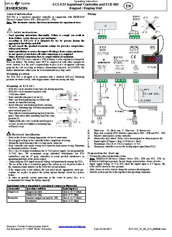
W i r i n g :
A:
White wire
E:
Plug cable assembly EXV-Mxx for connection to EX4…EX8 and FX5…FX9
G:
Remote control panel, system controller
H:
Alarm relay, dry contact. Relay coil is not energized at alarm or power off.
I:
Digital input (0V/open = Stop; 24V/closed = Start)
J:
Transformer Class II, 24 VAC secondary / 25 VA
K:
Third party controller (can use the analog output signal from EC3)
P r e p a r a t i o n f o r S t a r t — u p :
• Vacuum the entire refrigeration system
• Note: EMERSON Electrical Control Valves EX4…EX8 and FX5…FX9 are
delivered at half open position. Do not charge system before closure of valve.
• Apply supply voltage 24 V to EC3 while the digital input is 0 V (open). The
valve will be driven to close position.
• After closure of valve, start to charge the system with refrigerant.
• Start the system and check the superheat and operating conditions.
Date: 03.04.2017
B: Black wire C: Blue wire D: Brown wire
EC3-X33_OI_ML_R12_865009.docx
Бренд: Emerson
Категория для инструкций: Автоматика, регуляторы, модули, термостаты
Алфавит (англ.): E
Описание: Универсальные контроллеры перегрева Emerson серии EC3-X33 с дисплеем ECD-002 для работы с электрическими регулирующими клапанами Emerson с шаговым двигателем серии EX4 EX8 и FX5…FX9. Руководство по эксплуатации
Размер файла: 1935829 байт
Инструкция на контроллеры перегрева Emerson серии EC3-X33 с дисплеем ECD-002
E C D — 0 0 2 d i s p l a y / k e y p a d u n i t : ( L E D s a n d b u t t o n f u n c t i o n s )
Blinking: valve is opening
ON: valve is fully open
Blinking: valve is closing
ON: valve is fully close
ON: demand
OFF: no demand
ON: alarm
Prg&Sel (5 sec)
OFF: no alarm
Manual reset for
blinking alarm codes
S e t u p o f ma i n p a r a me t e r s u s i n g E C D — 0 0 2 :
(need to be checked/modified before start-up)
• Make sure that digital input is 0V (open). Turn the power supply ON.
• Important: Three main parameters i.e. refrigerant type (u0), pressure sensor type
(uP) and valve type (ut) can be set only when digital input is open (0V) while the
power supply is ON (24 V). This feature is for added safety to prevent accidental
damage of compressors and other system components.
• For easy setting of main parameters, follow the pictorial procedure of «Quick
start-up» on the attached individual paper.
• Once the main parameters have been selected/saved the EC3 is ready for
startup. All other parameters can be modified at any time during operation
or standby if it is necessary.
P r o c e d u r e f o r p a r a me t e r s m o d i f i c a t i o n u s i n g E C D — 0 0 2 :
• The parameters can be accessed via the 4-button keypad. The configuration
parameters are protected by a numerical password. The default password is «12».
To select the parameter configuration:
• Press the PRG button for more than 5 seconds. A flashing «0» is displayed
• Press
or
until «12» is displayed; (password)
• Press SEL to confirm password
• Press
or
to show the code of the parameter that has to be changed;
• Press SEL to display the selected parameter value;
• Press
or
to increase or decrease the value;
• Press SEL to temporarily confirm the new value and display its code;
• Repeat the procedure from the beginning «press
• To exit and save the new settings: Press PRG to confirm the new values and
exit the parameters modification procedure.
• To exit without modifying any parameters: Do not press any button for at least
60 seconds (TIME OUT).
R e s e t a l l p a r a me t e r s t o f a c t o r y s e t t i n g :
• Make sure that digital input is 0V (open).
• Press
and
together for more than 5 seconds. A flashing «0» is displayed.
• Press
or
until the password is displayed (Factory setting = 12).
If password was changed, select the new password.
• Press SEL to confirm password
«0» is displayed.
• Press SEL to reset all parameters to factory setting
• Press PRG to activate the function and leave the special function mode.
C o n t r o l ( v a l v e ) s t a r t — u p b e h a v i o r : ( P a r a me t e r u u a n d u 9 )
EX4/5/6 ≤ 1.5 seconds
EX7 ≤ 3.2 seconds
uu
EX8 ≤ 7.2 seconds
≤ 7.3 seconds
FX5-8
FX9 ≤ 9.7 seconds
Emerson Climate Technologies GmbH
Am Borsigturm 31 I 13507 Berlin I Germany
EC3-X33 Superheat Controller and ECD-002
Keypad / Display Unit
Parameters setting/saving
Next parameter/
value (higher)
Selecting/confirming
or
to show…»
%
Sec.
u9
www.emersonclimate.eu
Operating instruction
M a i n p a r a me t e r s :
(must be checked and modified if necessary)
Code
Parameter description and choices
H5 Password
u0 System refrigerant
0 = R22 1 = R134a
5 = R410A
8 = R407A
12 = R449A
uP Installed pressure sensor type
0 = PT5-07x (for R22 / R134a / R507 / R404A / R407A / R407C /
1 = PT5-18x (for R410A/ R32)
2 = PT5-30x (for R410A / R744 / R32)
Next parameter/
3 = PT5-50x (for R744)
value (lower)
ut
Installed valve type
1 = EX4
5 = EX8
9 = FX7
O p t i o n a l p a r a me t e r s :
(recommended factory setting for majority of applications)
Code
Parameter description and choices
uu Start valve opening (%)
u9 Start opening duration (second)
uL Low superheat alarm function
0 = disable (for flooded evaporator)
1 = enable auto reset
Cut-out at 0.5K (if it maintains 1 min.); Cut-in immediately at 3K
u5 Superheat set-point (K)
If uL enabled (auto or manual)
If uL disabled
u2 MOP function
0 = disable 1 = enable
u3 MOP set-point (°C) saturation temperature
**) Factory setting is according to selected refrigerant (u0):
+13°C — R22
+7°C — R404A
+50°C — R124
+10°C — R407F
+12°C — R449A
+24°C — R1234ze
*) Min. and Max. setting values are dependant to selected type of
refrigerant
┌┘
5 Units conversion (only for u3, u5,
0 = °C, K, bar 1 = °F, R, psig
(Psig values are divided by 10. Example: Display 12.5 is 125 psig)
┌┘
1 Value to show
0 = Measured superheat (K) 1 = Measured evaporating pressure, (bar);
2 = Valve opening (%)
4 = Calculated evaporating temperature (°C) from the pressure
u4 Superheat control mode
0 = Standard,
2 = intermediate control
b1 Battery error management, when battery is
defective, see below
value
0
1
2
3
When setting b1 to option 0 or 1, the user must ensure appropriate
!
safety precautions are in place to protect the system against damage
caused by a power failure.
uF Control range valve %
*) Notes for R32: R32 is classified as low flammable refrigerant in Europe. EC3-
X33 is designed under consideration of European safety standards and directives
for none flammable refrigerants. The use of EC3-X33 with R32 is for
systems/regions which it does not require consideration of additional safety
standards as for flammable refrigerant.
After selecting the parameters the EC3-X33 is fully functional without
keypad/display unit. ECD-002 may be removed or connected at any time.
Date: 03.04.2017
2 = R507 3 = R404A
6 = R124 7 = R744 (subcritical application)
9 = R407F
10 = R32*
13 = R450A
14 = R513A
R407F / R124 / R448A /R449A / R450A / R513A /
R1234ze)
2 = EX5
3 = EX6
6 = FX5
7 = FX6
10 = FX7.5
11 = FX8
2 = enable manual reset
+15°C — R134a
+15°C — R407C
-5°C — R744
+10°C — R32
+19°C — R450A
┌┘
1)
3 = Measured coil-out temperature (°C)
1 = Slow
Alarm
display
Alarm relay
Valve
—
—
Regulating
Ab
—
Regulating
Ab
Signalling
Fully close
Ab
Signalling
Fully close
(blinking)
EC3-X33_OI_ML_R12_865009.docx
Factory
Field
Min Max
setting
setting
1
199
12
0
16
1
4 = R407C
11 = R448A
15 = R1234ze
0
3
0
1
12
5
4 = EX7
8 = FX6.5
12=FX9
Factory
Field
Min Max
setting
setting
0
100
50
0
120
5
0
2
1
3
30
6
0.5
30
6
0
1
1
*
*
**
+7°C — R507
+15°C — R410A
+10°C — R407A
+12°C — R448A
+13°C — R513A
0
1
0
0
4
0
0
2
0
0
3
2
Reset possibility after
recovery/replacement
—
—
Auto
Manual
5
100
100
Specifications:1588/1588914-ec3x33.pdf file (17 Mar 2023) |
Accompanying Data:
Emerson EC3-X33 Controller, Monitor PDF Operating Instruction (Updated: Friday 17th of March 2023 09:50:56 PM)
Rating: 4.4 (rated by 25 users)
Compatible devices: DIXELL XR77CHC, PMAC II Solo, Dixell Wing XW263L, Bettis G10 Series, DSM314, TESCOM 44-1300 Series, EC3-751, Unidrive M400.
Recommended Documentation:
Text Version of Manual, Operating Instruction
(Ocr-Read Summary of Contents of some pages of the Emerson EC3-X33 Document (Main Content), UPD: 17 March 2023)
-
11, Instructions de service EC3-X33 Contrôleur de surchauffe et afficheur déporté ECD-002 Emerson Climate Technologies GmbH www.emersonclimate.eu Am Borsigturm 31 I 13507 Berlin I Germany Date: 03.04.2017 EC3-X33_OI_ML_R12_865009.docx Messages d’erreur: Code alarme Description Paramètre…
-
20, Emerson EC3-X33 Instruzioni operative Controllo del surriscaldamento EC3-X33 e Unità Display ECD-002 Emerson Climate Technologies GmbH www.emersonclimate.eu Am Borsigturm 31 I 13507 Berlin I Germany Date: 03.04.2017 EC3-X33_OI_ML_R12_865009.docx Dati Tecnici: Alimentazione 24 VAC ±10%; 50/60 Hz;…
-
24, Emerson EC3-X33 Руководство по эксплуатации Контроллер перегрева EC3-X33 и дисплей ECD-002 Emerson Climate Technologies GmbH www.emersonclimate.eu Am Borsigturm 31 I 13507 Berlin I Germany Date: 03.04.2017 EC3-X33_OI_ML_R12_865009.docx Тех�…
-
5, Betriebsanleitung EC3-X33 Überhitzungsregler mit ECD-002 Anzeige- / Einstelleinheit Emerson Climate Technologies GmbH www.emersonclimate.eu Am Borsigturm 31 I 13507 Berlin I Germany Date: 03.04.2017 EC3-X33_OI_ML_R12_865009.docx Beschreibung: EC3-X33 sind universelle Überhitzungsregler…
-
25, EC3-X33 Superheat Controller and ECD-002 Keypad / Display Unit Emerson Climate Technologies GmbH www.emersonclimate.eu Am Borsigturm 31 I 13507 Berlin I Germany Date: 03.04.2017 EC3-X33_OI_ML_R12_865009.docx 0 1 1a 1b 1c 1d 1e 2 2a…
-
Emerson EC3-X33 User Manual
-
Emerson EC3-X33 User Guide
-
Emerson EC3-X33 PDF Manual
-
Emerson EC3-X33 Owner’s Manuals
Recommended: C711WT, QD-4240, NSVS1151


-
UPS ZINTO A Series
Benutzerhandbuch ONLINE ZINTO A-Serie Deutsch: Seite 3 — 62English: Page 63 — 120Italia: Pagina 121 — 181 Deutschland Italien Schweiz ONLINE USV-Systeme AG Dreimühlenstr. 4 D-80469 München Phone +49 (0) 89 / 2423990-10 Fax +49 (0) 89 / 2423990-20 www.online-usv.de ONLINE UPS-Systems S …
ZINTO A Series 181
-
Danfoss FC 300
FC 300 Design GuideContents! How to Read this Design Guide ………………………………………….. 5″ How to Read this Design Guide ………………………………………………………… 5″ Approvals ………………………………………………………………… …
FC 300 309
-
Trane Tracer UC210
SAFETY WARNINGOnly qualified personnel should install and service the equipment. The installation, starting up, and servicing of heating, ventilating, and air-conditioning equipment can be hazardous and requires specific knowledge and training. Improperly installed, adjusted or altered equipment by an unqualif …
Tracer UC210 72
-
Philips Dynalite DRC810DT
WMGD Pty Limited trading as Dynalite ABN 33 097 246 92 Unit 6, 691 Gardeners Road Mascot NSW 2020 Australia t +61 8338 9899 f +61 2 8338 9333 [email protected] dynalite-online.com DRC810DT SPDT Dry Contact Relay Controller Installation Manual contents Warning…… …
Dynalite DRC810DT 10
Additional Information:
Popular Right Now:
Operating Impressions, Questions and Answers: