-
Contents
-
Table of Contents
-
Troubleshooting
-
Bookmarks
Quick Links
Proline Promass F 100 Coriolis Flowmeter
Modbus RS485
Operating Instructions Manual
BA01659O/06/EN/02.17
Valid as of version 01.03 zz (Device firmware)
71382654
MANUAL
Related Manuals for Endress+Hauser Proline Promass F 100
Summary of Contents for Endress+Hauser Proline Promass F 100
-
Page 1
MANUAL Proline Promass F 100 Coriolis Flowmeter Modbus RS485 Operating Instructions Manual BA01659O/06/EN/02.17 Valid as of version 01.03 zz (Device firmware) 71382654… -
Page 2
• The manufacturer reserves the right to modify technical data without prior notice. Your Endress+Hauser Sales Center will supply you with current information and updates to these instructions. Important All information and technical specifications in this documentation have been carefully checked and compiled by the author. -
Page 3: Table Of Contents
Proline Promass F 100 Modbus RS485 Table of contents Table of contents About this document ….6 Installation ….. . . 20 Document function .
-
Page 4
……68 13.3 Endress+Hauser services ….89 10.7.1 Write protection via write protection… -
Page 5
Proline Promass F 100 Modbus RS485 Table of contents 16.4 Output …… -
Page 6: About This Document
About this document Proline Promass F 100 Modbus RS485 About this document Document function These Operating Instructions contain all the information that is required in various phases of the life cycle of the device: from product identification, incoming acceptance and storage, to mounting, connection, operation and commissioning through to troubleshooting, maintenance and disposal.
-
Page 7: Tool Symbols
Proline Promass F 100 Modbus RS485 About this document 1.2.3 Tool symbols Symbol Meaning Allen key Open-ended wrench 1.2.4 Symbols for certain types of information Symbol Meaning Permitted Procedures, processes or actions that are permitted. Preferred Procedures, processes or actions that are preferred.
-
Page 8: Documentation
• The W@M Device Viewer : Enter the serial number from the nameplate (www.endress.com/deviceviewer) • The Endress+Hauser Operations App: Enter the serial number from the nameplate or scan the 2-D matrix code (QR code) on the nameplate. For a detailed list of the individual documents along with the documentation code →…
-
Page 9
Proline Promass F 100 Modbus RS485 About this document Microsoft® Registered trademark of the Microsoft Corporation, Redmond, Washington, USA TRI-CLAMP® Registered trademark of Ladish & Co., Inc., Kenosha, USA… -
Page 10: Basic Safety Instructions
Basic safety instructions Proline Promass F 100 Modbus RS485 Basic safety instructions Requirements for the personnel The personnel for installation, commissioning, diagnostics and maintenance must fulfill the following requirements: ‣ Trained, qualified specialists must have a relevant qualification for this specific function and task.
-
Page 11: Workplace Safety
Verification for borderline cases: ‣ For special fluids and fluids for cleaning, Endress+Hauser is glad to provide assistance in verifying the corrosion resistance of fluid-wetted materials, but does not accept any warranty or liability as minute changes in the temperature, concentration or level of contamination in the process can alter the corrosion resistance properties.
-
Page 12: Product Safety
It meets general safety standards and legal requirements. It also complies with the EU directives listed in the device-specific EU Declaration of Conformity. Endress+Hauser confirms this by affixing the CE mark to the device.
-
Page 13: Product Description
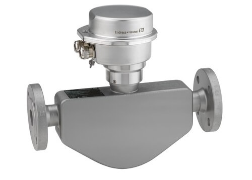
Proline Promass F 100 Modbus RS485 Product description Product description The device consists of a transmitter and a sensor. The Safety Barrier Promass 100 is part of the scope of supply and must be implemented to operate the device. The device is available as a compact version: The transmitter and sensor form a mechanical unit.
-
Page 14: Identification
A0028673 and documents present? • If one of the conditions is not satisfied, contact your Endress+Hauser Sales Center. • Depending on the device version, the CD-ROM might not be part of the delivery! The Technical Documentation is available via the Internet or via the Endress+Hauser…
-
Page 15: Product Identification
• Enter the serial number from the nameplates into the Endress+Hauser Operations App or scan the 2-D matrix code (QR code) on the nameplate with the Endress+Hauser Operations App: all the information for the measuring device is displayed. For an overview of the scope of the associated Technical Documentation, refer to the following: •…
-
Page 16: Sensor Nameplate
Incoming acceptance and product identification Proline Promass F 100 Modbus RS485 4.2.2 Sensor nameplate Order code: Ser. no.: Ext. ord. cd.: Date: A0029199 3 Example of a sensor nameplate Name of the sensor Manufacturing location Order code Serial number (ser. no.) Extended order code (Ext.
-
Page 17: Symbols On Measuring Device
Proline Promass F 100 Modbus RS485 Incoming acceptance and product identification 4.2.3 Promass 100 safety barrier nameplate Safe area NON intrinsically safe circuit (grey terminals) Promass 100 Safety Barrier Intrinsically safe circuits (blue terminals) HAZARDOUS area A0017854 4 Example of a Promass 100 safety barrier nameplate Non-hazardous area or Zone 2/Div.
-
Page 18: Storage And Transport
Storage and transport Proline Promass F 100 Modbus RS485 Storage and transport Storage conditions Observe the following notes for storage: ‣ Store in the original packaging to ensure protection from shock. ‣ Do not remove protective covers or protective caps installed on process connections.
-
Page 19: Measuring Devices With Lifting Lugs
Proline Promass F 100 Modbus RS485 Storage and transport A0029214 5.2.2 Measuring devices with lifting lugs CAUTION Special transportation instructions for devices with lifting lugs ‣ Only use the lifting lugs fitted on the device or flanges to transport the device.
-
Page 20: Installation
Installation Proline Promass F 100 Modbus RS485 Installation Installation conditions No special measures such as supports are necessary. External forces are absorbed by the construction of the device. 6.1.1 Mounting position Mounting location A0028772 To prevent measuring errors arising from accumulation of gas bubbles in the measuring tube, avoid the following mounting locations in the pipe: •…
-
Page 21
Proline Promass F 100 Modbus RS485 Installation A0028773 5 Installation in a down pipe (e.g. for batching applications) Supply tank Sensor Orifice plate, pipe restriction Valve Batching tank Ø orifice plate, pipe restriction [mm] [in] [mm] [in] ³⁄₈ 0.24 ½… -
Page 22
Installation Proline Promass F 100 Modbus RS485 Orientation Recommendation Horizontal orientation, transmitter at bottom Exceptions: → 6, 22 A0015590 Horizontal orientation, transmitter at side A0015592 Applications with low process temperatures may decrease the ambient temperature. To maintain the minimum ambient temperature for the transmitter, this orientation is recommended. -
Page 23: Process
Proline Promass F 100 Modbus RS485 Installation 6.1.2 Requirements from environment and process Ambient temperature range Measuring device • –40 to +60 °C (–40 to +140 °F) • Order code for «Test, certificate», option JM: –50 to +60 °C (–58 to +140 °F) Safety Barrier Promass 100 –40 to +60 °C (–40 to +140 °F)
-
Page 24
Installation Proline Promass F 100 Modbus RS485 NOTICE Electronics overheating on account of thermal insulation! ‣ Recommended orientation: horizontal orientation, transmitter housing pointing downwards. ‣ Do not insulate the transmitter housing . ‣ Maximum permissible temperature at the lower end of the transmitter housing: 80 °C (176 °F) -
Page 25: Special Mounting Instructions
Proline Promass F 100 Modbus RS485 Installation The sheet must have the following properties: • Relative magnetic permeability µr ≥ 300 • Plate thickness d ≥ 0.35 mm (d ≥ 0.014 in) Vibrations The high oscillation frequency of the measuring tubes ensures that the correct operation of the measuring system is not influenced by plant vibrations.
-
Page 26: Mounting The Measuring Device
Installation Proline Promass F 100 Modbus RS485 DN 8 ( «)…150 (6″) DN 250 (10″) ⁄ RUPTURE DISK A0028903 Rupture disk label Rupture disk with 1/2″ NPT internal thread with 1» width across flat Transport protection Zero point adjustment All measuring devices are calibrated in accordance with state-of-the-art technology.
-
Page 27: Mounting The Measuring Device
Proline Promass F 100 Modbus RS485 Installation 6.2.3 Mounting the measuring device WARNING Danger due to improper process sealing! ‣ Ensure that the inside diameters of the gaskets are greater than or equal to that of the process connections and piping.
-
Page 28: Electrical Connection
Electrical connection Proline Promass F 100 Modbus RS485 Electrical connection NOTICE The measuring device does not have an internal circuit breaker. ‣ For this reason, assign the measuring device a switch or power-circuit breaker so that the power supply line can be easily disconnected from the mains.
-
Page 29: Terminal Assignment
Proline Promass F 100 Modbus RS485 Electrical connection Signal damping Max. 9 dB over the entire length of the cable cross-section Shield Copper braided shielding or braided shielding with foil shield. When grounding the cable shield, observe the grounding concept of the plant.
-
Page 30
Electrical connection Proline Promass F 100 Modbus RS485 Depending on the housing version, the transmitters can be ordered with terminals or device plugs. Connection methods available Order code Possible options for order code Power «Housing» «Electrical connection» Output supply Options… -
Page 31
Proline Promass F 100 Modbus RS485 Electrical connection Depending on the housing version, the transmitters can be ordered with terminals or device plugs. Connection methods available Order code Possible options for order code Power «Housing» «Electrical connection» Output supply Options… -
Page 32: Pin Assignment, Device Plug
Electrical connection Proline Promass F 100 Modbus RS485 Safety Barrier Promass 100 Power Modbus supply RS485 Safe area Power Lift panel for bus termination Communication Safety Barrier Promass 100 Hazardous area Power Modbus supply RS485 A0030220 10 Safety Barrier Promass 100 with terminals…
-
Page 33: Shielding And Grounding
Proline Promass F 100 Modbus RS485 Electrical connection Grounding/shielding Coding Plug/socket Plug Signal transmission Promass Device plug for signal transmission (device side), MODBUS RS485 (not intrinsically safe) For use in the non-hazardous area and Zone 2/Div. 2. Assignment Not assigned…
-
Page 34: Preparing The Measuring Device
Electrical connection Proline Promass F 100 Modbus RS485 7.1.6 Preparing the measuring device NOTICE Insufficient sealing of the housing! Operational reliability of the measuring device could be compromised. ‣ Use suitable cable glands corresponding to the degree of protection. 1. Remove dummy plug if present.
-
Page 35: Promass 100
Proline Promass F 100 Modbus RS485 Electrical connection 8 mm 8 mm 3 mm 10 (0.4) mm (in) A0017844 12 Device versions with connection examples Cable Device plug for signal transmission Device plug for supply voltage ‣ Connect the cable in accordance with the terminal assignment or the device plug pin assignment .
-
Page 36: Ensure Potential Equalization
Electrical connection Proline Promass F 100 Modbus RS485 L- L+ A0028766 13 Electrical connection between the transmitter and Safety Barrier Promass 100 Control system (e.g. PLC) Observe cable specifications → 28 Safety Barrier Promass 100: terminal assignment → 32 Observe cable specifications →…
-
Page 37: Special Connection Instructions
Proline Promass F 100 Modbus RS485 Electrical connection Special connection instructions 7.3.1 Connection examples Modbus RS485 Modbus RS485, non-hazardous area and Zone 2/Div. 2 A0028765 14 Connection example for Modbus RS485, non-hazardous area and Zone 2/Div. 2 Control system (e.g. PLC) Cable shield: the cable shield must be grounded at both ends to comply with EMC requirements;…
-
Page 38: Ensuring The Degree Of Protection
Electrical connection Proline Promass F 100 Modbus RS485 Ensuring the degree of protection The measuring device fulfills all the requirements for the IP66/67 degree of protection, Type 4X enclosure. To guarantee IP66/67 degree of protection, Type 4X enclosure, carry out the following steps after the electrical connection: 1.
-
Page 39: Operation Options
Proline Promass F 100 Modbus RS485 Operation options Operation options Overview of operating options A0017760 Computer with «FieldCare» or «DeviceCare» operating tool via Commubox FXA291 and service interface Control system (e.g. PLC)
-
Page 40: Menu
Operation options Proline Promass F 100 Modbus RS485 Structure and function of the operating menu 8.2.1 Structure of the operating menu For an overview of the operating menu for experts: «Description of Device Parameters» document supplied with the device→ 116…
-
Page 41
Proline Promass F 100 Modbus RS485 Operation options Operating menu for operators and maintenances Language Operatation Language Parameter 1 Parameter n Submenu 1 Submenu n Setup Device tag Wizard 1 / Parameter 1 Wizard n / Parameter n Advanced setup… -
Page 42: Operating Philosophy
Operation options Proline Promass F 100 Modbus RS485 8.2.2 Operating philosophy The individual parts of the operating menu are assigned to certain user roles (operator, maintenance etc.). Each user role contains typical tasks within the device lifecycle. Menu/parameter User role and tasks…
-
Page 43: Access To The Operating Menu Via The Operating Tool
Computer with «FieldCare» operating tool with COM DTM «CDI Communication FXA291» Via service interface (CDI) A0014019 Service interface (CDI = Endress+Hauser Common Data Interface) of the measuring device Commubox FXA291 Computer with FieldCare operating tool with COM DTM CDI Communication FXA291…
-
Page 44: Fieldcare
FieldCare Function scope FDT-based plant asset management tool from Endress+Hauser. It can configure all smart field devices in a system and helps you manage them. By using the status information, it is also a simple but effective way of checking their status and condition.
-
Page 45: Devicecare
DeviceCare Function scope Tool to connect and configure Endress+Hauser field devices. The fastest way to configure Endress+Hauser field devices is with the dedicated «DeviceCare» tool. Together with the device type managers (DTMs) it presents a convenient, comprehensive solution. For details, see Innovation Brochure IN01047S Source for device description files See information →…
-
Page 46: System Integration
System integration Proline Promass F 100 Modbus RS485 System integration Overview of device description files 9.1.1 Current version data for the device Firmware version 01.03.zz • On the title page of the Operating Instructions • On the transmitter nameplate • Firmware version Diagnostics →…
-
Page 47
Proline Promass F 100 Modbus RS485 System integration Code Name Description Application Read holding Master reads one or more Modbus Read device parameters with read register registers from the device. and write access A maximum of 125 consecutive Example: registers can be read with 1… -
Page 48: Register Information
System integration Proline Promass F 100 Modbus RS485 9.2.2 Register information For an overview of device parameters with their respective Modbus register information, please refer to the «Modbus RS485 register information» section in the «Description of device parameters» documentation .
-
Page 49
Proline Promass F 100 Modbus RS485 System integration 3 – 2 – 1 – 0 Byte 3 Byte 2 Byte 1 Byte 0 (SEEEEEEE) (EMMMMMMM) (MMMMMMMM) (MMMMMMMM) * = factory setting, S = sign, E = exponent, M = mantissa… -
Page 50
System integration Proline Promass F 100 Modbus RS485 Scan list configuration For configuration, the Modbus RS485 register addresses of the device parameters to be grouped must be entered in the scan list. Please note the following basic requirements of the scan list: Max. -
Page 51
Proline Promass F 100 Modbus RS485 System integration Data area Device parameter value Modbus RS485 register Data type* Access** Start register End register (Float only) Value of scan list register … Value of scan list register 15 5081 5082 Integer/float Read/write * Data type depends on the device parameters entered in the scan list. -
Page 52
Commissioning Proline Promass F 100 Modbus RS485 Commissioning 10.1 Function check Before commissioning the measuring device: ‣ Make sure that the post-installation and post-connection checks have been performed. • «Post-installation check» checklist→ 27 • «Post-connection check» checklist → 38 10.2… -
Page 53: Defining The Tag Name
Proline Promass F 100 Modbus RS485 Commissioning 10.4.1 Defining the tag name To enable fast identification of the measuring point within the system, you can enter a unique designation using the Device tag parameter and thus change the factory setting.
-
Page 54
Commissioning Proline Promass F 100 Modbus RS485 Parameter overview with brief description Parameter Description Selection Factory setting Mass flow unit Select mass flow unit. Unit choose list Country-specific: • kg/h Result • lb/min The selected unit applies for: • Output •… -
Page 55
Proline Promass F 100 Modbus RS485 Commissioning Parameter Description Selection Factory setting Temperature unit Select temperature unit. Unit choose list Country-specific: • °C Result • °F The selected unit applies for: • Electronic temperature parameter (6053) • Maximum value parameter (6051) •… -
Page 56
Commissioning Proline Promass F 100 Modbus RS485 10.4.3 Selecting and setting the medium The Select medium wizard submenu contains parameters that must be configured in order to select and set the medium. Navigation «Setup» menu → Medium selection ‣ Medium selection Select medium →… -
Page 57: Interface
Proline Promass F 100 Modbus RS485 Commissioning Parameter overview with brief description Parameter Prerequisite Description Selection / User Factory setting entry Select medium – Select medium type. • Liquid Liquid • Gas Select gas type The Gas option is selected in Select measured gas type.
-
Page 58
Commissioning Proline Promass F 100 Modbus RS485 Navigation «Setup» menu → Communication ‣ Communication Bus address → 58 → 58 Baudrate Data transfer mode → 58 Parity → 58 Byte order → 58 Failure mode →… -
Page 59
Proline Promass F 100 Modbus RS485 Commissioning Parameter Description User entry / Selection Factory setting Assign diagnostic behavior Select diagnostic behavior for MODBUS • Off Alarm communication. • Alarm or warning • Warning • Alarm Failure mode Select measured value output behavior when •… -
Page 60
Commissioning Proline Promass F 100 Modbus RS485 10.4.5 Configuring the low flow cut off The Low flow cut off submenu contains the parameters that must be set in order to configure the low flow cut off. Navigation «Setup» menu → Low flow cut off ‣… -
Page 61
Proline Promass F 100 Modbus RS485 Commissioning 10.4.6 Configuring the partial filled pipe detection The Partially filled pipe detection submenu contains parameters that have to be set for configuring empty pipe detection. Navigation «Setup» menu → Partially filled pipe detection ‣… -
Page 62: Enter Access Code
Commissioning Proline Promass F 100 Modbus RS485 10.5 Advanced settings The Advanced setup submenu together with its submenus contains parameters for specific settings. The number of submenus can vary depending on the device version, e.g. viscosity is available only with the Promass I.
-
Page 63
Proline Promass F 100 Modbus RS485 Commissioning Navigation «Setup» menu → Advanced setup → Calculated values ‣ Calculated values ‣ Corrected volume flow calculation → 63 Corrected volume flow calculation External reference density → 63 Fixed reference density →… -
Page 64: Sensor Adjustment
Commissioning Proline Promass F 100 Modbus RS485 Parameter Prerequisite Description Selection / User Factory setting interface / User entry Linear expansion coefficient The Calculated reference Enter linear, medium-specific Signed floating-point density option is selected in expansion coefficient for number the Corrected volume flow calculating the reference calculation parameter density.
-
Page 65: Totalizer 1 To N
Proline Promass F 100 Modbus RS485 Commissioning Navigation «Setup» menu → Advanced setup → Sensor adjustment → Zero point adjustment ‣ Zero point adjustment Zero point adjustment control → 65 → 65 Progress Parameter overview with brief description…
-
Page 66: Administration
Commissioning Proline Promass F 100 Modbus RS485 Parameter overview with brief description Parameter Prerequisite Description Selection Factory setting Assign process variable – Select process variable for • Off Mass flow totalizer. • Mass flow • Volume flow • Corrected volume flow •…
-
Page 67
Proline Promass F 100 Modbus RS485 Commissioning Parameter overview with brief description Parameter Description Selection Factory setting Device reset Reset the device configuration — either • Cancel Cancel entirely or in part — to a defined state. • To delivery settings •… -
Page 68
Commissioning Proline Promass F 100 Modbus RS485 Parameter overview with brief description Parameter Prerequisite Description Selection / User Factory setting entry Assign simulation process variable – Select a process variable for • Off the simulation process that is • Mass flow activated. -
Page 69
Proline Promass F 100 Modbus RS485 Commissioning A0030224 Setting the write protection switch on the main electronics module to the On position enables hardware write protection. Setting the write protection switch on the main electronics module to the Off position (factory setting) disables hardware write protection. -
Page 70
Operation Proline Promass F 100 Modbus RS485 Operation 11.1 Reading the device locking status Device active write protection: Locking status parameter Navigation «Operation» menu → Locking status Function scope of «Locking status» parameter Options Description Hardware locked The locking switch (DIP switch) for locking the hardware is activated on the main electronic module. -
Page 71
Proline Promass F 100 Modbus RS485 Operation Navigation «Diagnostics» menu → Measured values → Measured variables ‣ Measured variables Mass flow → 71 → 71 Volume flow Corrected volume flow → 71 Density → 71 Reference density →… -
Page 72
Operation Proline Promass F 100 Modbus RS485 Parameter Prerequisite Description User interface Reference density – Displays the reference density currently Signed floating-point calculated. number Dependency The unit is taken from the Reference density unit parameter (→ 54). Temperature –… -
Page 73: Performing A Totalizer Reset
Proline Promass F 100 Modbus RS485 Operation Navigation «Diagnostics» menu → Measured values → Totalizer ‣ Totalizer Totalizer value 1 to n → 73 → 73 Totalizer overflow 1 to n Parameter overview with brief description Parameter Prerequisite…
-
Page 74
Operation Proline Promass F 100 Modbus RS485 Navigation «Operation» menu → Totalizer handling ‣ Totalizer handling Control Totalizer 1 to n → 74 → 74 Preset value 1 to n Reset all totalizers → 74 Parameter overview with brief description… -
Page 75: Totalizer» Parameter
Proline Promass F 100 Modbus RS485 Operation 11.5.1 Function scope of the «Control Totalizer» parameter Options Description Totalize The totalizer is started or continues running. Reset + hold The totaling process is stopped and the totalizer is reset to 0.
-
Page 76: General Troubleshooting
Diagnostics and troubleshooting Proline Promass F 100 Modbus RS485 Diagnostics and troubleshooting 12.1 General troubleshooting For output signals Error Possible causes Solution Green power LED on the main Supply voltage does not match the Apply the correct supply voltage .
-
Page 77: Diodes
Proline Promass F 100 Modbus RS485 Diagnostics and troubleshooting Error Possible causes Solution Operation with FieldCare or Firewall of computer or network is Depending on the settings of the DeviceCare via CDI-RJ45 service preventing communication firewall used on the computer or in…
-
Page 78
Diagnostics and troubleshooting Proline Promass F 100 Modbus RS485 Xxxxxx/…/…/ Device name: Xxxxxxx kg/h Mass flow: 12.34 Device tag: Xxxxxxx Volume flow: 12.34 ³ m /h Status signal: Function check (C) Xxxxxx Diagnostics 1: C485 Simu… Remedy information: Deactivate… Failure (F) -
Page 79
Proline Promass F 100 Modbus RS485 Diagnostics and troubleshooting Diagnostic information Diagnostic code Status signal Diagnostic number Short text ↓ ↓ ↓ Example Process limit A0013958 3-digit number 12.3.2 Calling up remedy information Remedy information is provided for every diagnostic event to ensure that problems can be rectified quickly: •… -
Page 80
Diagnostics and troubleshooting Proline Promass F 100 Modbus RS485 Parameter overview with brief description Parameters Description Selection Factory setting Failure mode Select measured value • NaN value NaN value output behavior when a • Last valid value diagnostic message occurs … -
Page 81
Proline Promass F 100 Modbus RS485 Diagnostics and troubleshooting Diagnostic Short text Remedy instructions Status Diagnostic number signal behavior [from the [from the factory] factory] Sensor limit exceeded 1. Inspect sensor Alarm 2. Check process condition Sensor connection 1. Change main electronic… -
Page 82
Diagnostics and troubleshooting Proline Promass F 100 Modbus RS485 Diagnostic Short text Remedy instructions Status Diagnostic number signal behavior [from the [from the factory] factory] Simulation measured Deactivate simulation Warning variable Special event 3 Contact service Alarm Special event 7… -
Page 83
Proline Promass F 100 Modbus RS485 Diagnostics and troubleshooting 12.7 Pending diagnostic events The Diagnostics menu allows the user to view the current diagnostic event and the previous diagnostic event separately. To call up the measures to rectify a diagnostic event: •… -
Page 84
Diagnostics and troubleshooting Proline Promass F 100 Modbus RS485 Navigation path Diagnostics → Diagnostic list To call up the measures to rectify a diagnostic event: • Via «FieldCare» operating tool → 79 • Via «DeviceCare» operating tool → 79 12.9… -
Page 85
Proline Promass F 100 Modbus RS485 Diagnostics and troubleshooting 12.9.3 Overview of information events Unlike a diagnostic event, an information event is displayed in the event logbook only and not in the diagnostic list. Info number Info name I1000 ———(Device ok) -
Page 86
Diagnostics and troubleshooting Proline Promass F 100 Modbus RS485 Options Description To delivery settings Every parameter for which a customer-specific default setting was ordered is reset to this customer-specific value. All other parameters are reset to the factory setting. … -
Page 87
Proline Promass F 100 Modbus RS485 Diagnostics and troubleshooting Parameter Description User interface Factory setting Firmware version Shows the device firmware version installed. Character string in the format – xx.yy.zz Device name Shows the name of the transmitter. Max. 32 characters such as Promass 100 letters or numbers. -
Page 88
«Manufacturer’ s information» document. The manufacturer’ s information is available: • In the Download Area of the Endress+Hauser web site: www.endress.com → Downloads • Specify the following details: –… -
Page 89
→ 106. 13.2 Measuring and test equipment Endress+Hauser offers a wide variety of measuring and test equipment, such as W@M or device tests. Your Endress+Hauser Sales Center can provide detailed information on the services. List of some of the measuring and testing equipment: → 92 13.3… -
Page 90
• The measuring devices have a modular design. • Spare parts are grouped into logical kits with the associated Installation Instructions. • Repairs are carried out by Endress+Hauser Service or by appropriately trained customers. • Certified devices can only be converted to other certified devices by Endress+Hauser Service or at the factory. -
Page 91
Proline Promass F 100 Modbus RS485 Repairs 14.5 Disposal 14.5.1 Removing the measuring device 1. Switch off the device. WARNING Danger to persons from process conditions. ‣ Beware of hazardous process conditions such as pressure in the measuring device, high temperatures or aggressive fluids. -
Page 92
Various accessories, which can be ordered with the device or subsequently from Endress +Hauser, are available for the device. Detailed information on the order code in question is available from your local Endress+Hauser sales center or on the product page of the Endress+Hauser website: www.endress.com. -
Page 93
Tool for connecting and configuring Endress+Hauser field devices. For details, see Innovation brochure IN01047S Commubox FXA291 Connects Endress+Hauser field devices with a CDI interface (= Endress+Hauser Common Data Interface) and the USB port of a computer or laptop. For details, see «Technical Information» TI00405C 15.4… -
Page 94
Technical data Proline Promass F 100 Modbus RS485 Technical data 16.1 Application The measuring device is suitable for flow measurement of liquids and gases only. Depending on the version ordered, the measuring device can also measure potentially explosive, flammable, poisonous and oxidizing media. -
Page 95: Input
Proline Promass F 100 Modbus RS485 Technical data 16.3 Input Measured variable Direct measured variables • Mass flow • Density • Temperature Calculated measured variables • Volume flow • Corrected volume flow • Reference density Measuring range Measuring ranges for liquids Measuring range full scale values …
-
Page 96: Output
Technical data Proline Promass F 100 Modbus RS485 [mm] [in] [kg/m 1½ Calculation example for gas • Sensor: Promass F, DN 50 • Gas: Air with a density of 60.3 kg/m³ (at 20 °C and 50 bar) • Measuring range (liquid): 70 000 kg/h •…
-
Page 97
Proline Promass F 100 Modbus RS485 Technical data Current output 4 to 20 mA 4 to 20 mA Failure mode Choose from: • 4 to 20 mA in accordance with NAMUR recommendation NE 43 • 4 to 20 mA in accordance with US •… -
Page 98: Power Supply
Technical data Proline Promass F 100 Modbus RS485 Low flow cut off The switch points for low flow cut off are user-selectable. Galvanic isolation The following connections are galvanically isolated from each other: • Outputs • Power supply Protocol-specific data Protocol Modbus Applications Protocol Specification V1.1…
-
Page 99
Proline Promass F 100 Modbus RS485 Technical data Promass 100 safety barrier DC 20 to 30 V Power consumption Transmitter Maximum Order code for «Output» Power consumption Option M Modbus RS485, for use in non-hazardous areas and Zone 2/ 3.5 W Div. -
Page 100: Performance Characteristics
Technical data Proline Promass F 100 Modbus RS485 Cable entries • Cable gland: M20 × 1.5 with cable 6 to 12 mm (0.24 to 0.47 in) • Thread for cable entry: – M20 – G ½» – NPT ½» Cable specification →…
-
Page 101
Proline Promass F 100 Modbus RS485 Technical data Zero point stability Zero point stability [mm] [in] [kg/h] [lb/min] ³⁄₈ 0.030 0.001 ½ 0.200 0.007 0.540 0.019 1½ 2.25 0.083 3.50 0.129 0.330 14.0 0.514 32.0 1.17 88.0 3.23 Flow values Flow values as turndown parameter depending on nominal diameter. -
Page 102
Technical data Proline Promass F 100 Modbus RS485 1:10 1:20 1:50 1:100 1:500 [inch] [lb/min] [lb/min] [lb/min] [lb/min] [lb/min] [lb/min] 29 400 2 940 1 470 58.80 80 850 8 085 4 043 1 617 808.5 161.7 Accuracy of outputs The output accuracy must be factored into the measured error if analog outputs are used, but can be ignored for fieldbus outputs (e.g. -
Page 103
Proline Promass F 100 Modbus RS485 Technical data The effect is reduced if zero point adjustment is performed at process temperature. Density When there is a difference between the density calibration temperature and the process temperature, the typical measured error of the sensor is ±0.00005 g/cm… -
Page 104
Technical data Proline Promass F 100 Modbus RS485 [% o.r./bar] [% o.r./psi] [mm] [in] –0.008 –0.0006 –0.009 –0.0006 –0.007 –0.0005 –0.009 –0.0006 –0.009 –0.0006 Design fundamentals o.r. = of reading, o.f.s. = of full scale value BaseAccu = base accuracy in % o.r., BaseRepeat = base repeatability in % o.r. -
Page 105: Installation
Proline Promass F 100 Modbus RS485 Technical data 16.7 Installation «Mounting requirements» → 20 16.8 Environment Ambient temperature → 23 range Temperature tables Observe the interdependencies between the permitted ambient and fluid temperatures when operating the device in hazardous areas.
-
Page 106: Process
Technical data Proline Promass F 100 Modbus RS485 16.9 Process Medium temperature range Standard version –50 to +150 °C (–58 to +302 °F) Order code for «Measuring tube mat., wetted surface», option HA, SA, SB, SC Extended temperature version –50 to +240 °C (–58 to +464 °F) Order code for «Measuring tube…
-
Page 107
Proline Promass F 100 Modbus RS485 Technical data Pressure-temperature An overview of the pressure-temperature ratings for the process connections is ratings provided in the «Technical Information» document Secondary containment For the Standard version with the temperature range –50 to +150 °C (–58 to +302 °F), the sensor housing is filled with dry nitrogen gas and protects the electronics and mechanics inside. -
Page 108
Technical data Proline Promass F 100 Modbus RS485 In case of a tube failure, the pressure level inside the secondary containment will rise according to the operating process pressure. If the user judges that the secondary containment pressure rating/burst pressure does not provide an adequate safety margin, the device can be fitted with a rupture disk. -
Page 109: Mechanical Construction
Proline Promass F 100 Modbus RS485 Technical data 16.10 Mechanical construction Design, dimensions For the dimensions and installation lengths of the device, see the «Technical Information» document, «Mechanical construction» section. Weight All values (weight exclusive of packaging material) refer to devices with EN/DIN PN 40 flanges.
-
Page 110
Technical data Proline Promass F 100 Modbus RS485 Materials Transmitter housing • Order code for «Housing», option A «Compact, aluminum coated»: Aluminum, AlSi10Mg, coated • Order code for «Housing», option B «Compact, hygienic, stainless»: – Hygienic version, stainless steel 1.4301 (304) –… -
Page 111
Proline Promass F 100 Modbus RS485 Technical data Device plug Electrical connection Material Plug M12x1 • Socket: Stainless steel, 1.4404 (316L) • Contact housing: Polyamide • Contacts: Gold-plated brass Sensor housing • Acid and alkali-resistant outer surface • DN 08 to DN 150: stainless steel, 1.4301 (304) Optional: order code for «Sensor option», option CC: stainless steel, 1.4404 (316L) -
Page 112: Operability
Technical data Proline Promass F 100 Modbus RS485 Process connections • Fixed flange connections: – EN 1092-1 (DIN 2501) flange – EN 1092-1 (DIN 2512N) flange – Namur lengths in accordance with NE 132 – ASME B16.5 flange – JIS B2220 flange –…
-
Page 113: Certificates And Approvals
EU Directives. These are listed in the corresponding EU Declaration of Conformity along with the standards applied. Endress+Hauser confirms successful testing of the device by affixing to it the CE mark. C-Tick symbol The measuring system meets the EMC requirements of the «Australian Communications and Media Authority (ACMA)».
-
Page 114: Application Packages
The application packages can be ordered with the device or subsequently from Endress+Hauser. Detailed information on the order code in question is available from your local Endress+Hauser sales center or on the product page of the Endress+Hauser website: www.endress.com.
-
Page 115: Accessories
For an overview of the scope of the associated Technical Documentation, refer to the following: • The W@M Device Viewer : Enter the serial number from the nameplate (www.endress.com/deviceviewer) • The Endress+Hauser Operations App: Enter the serial number from the nameplate or scan the 2-D matrix code (QR code) on the nameplate.
-
Page 116
Technical data Proline Promass F 100 Modbus RS485 Standard documentation Brief Operating Instructions Brief Operating Instructions for the sensor Measuring device Documentation code Proline Promass F KA01357O Transmitter Brief Operating Instructions Measuring device Documentation code Proline Promass 100 KA01335D Technical Information… -
Page 117
Proline Promass F 100 Modbus RS485 Technical data Installation Instructions Contents Comment Installation instructions for spare part sets and accessories • Access the overview of all the available spare part sets via W@M Device Viewer → 90 • Accessories available for order with Installation Instructions → 92… -
Page 118: Index
Index Proline Promass F 100 Modbus RS485 Index 0 … 9 Design fundamentals Maximum measured error ….104 3-A approval ……113 Repeatability .
-
Page 119
Proline Promass F 100 Modbus RS485 Index Environment Inspection Impact resistance ……105 Received goods ……14 Shock resistance . -
Page 120
Index Proline Promass F 100 Modbus RS485 Menu Device information (Submenu) ….86 Diagnostics ……83 Diagnostics (Menu) . -
Page 121
Proline Promass F 100 Modbus RS485 Index Sensor System design Mounting ……. 27 Measuring system . -
Page 122
The specifications contained herein are subject to change without notice and any user of said specifications should verify from the manufacturer that the specifications are currently in ef- fect. Otherwise, the manufacturer assumes no responsibility for the use of specifications which may have been changed and are no longer in effect. Contact information is subject to change.
-
Contents
-
Table of Contents
-
Bookmarks
Quick Links
TI01351D/06/EN/02.18
71412496
2018-09-03
The flowmeter with minimum total cost of ownership and an ultra-compact
transmitter
Application
• Measuring principle operates independently of physical
fluid properties such as viscosity or density
• Accurate measurement of liquids and gases for a wide range
of standard applications
Device properties
• Compact dual-tube sensor
• Medium temperature up to +150 °C (+302 °F)
• Process pressure: up to 100 bar (1 450 psi)
• Robust, ultra-compact transmitter housing
• Highest degree of protection: IP69
• Local display available
Заказывайте на сайте: www.tinnova.ru/endress_hauser/ || Эл. почта: info@tinnova.ru
Products
Technical Information
Proline Promass E 100
Coriolis flowmeter
Solutions
Your benefits
• Cost-effective – multi-purpose device; an alternative to
conventional volumetric flowmeters
• Fewer process measuring points – multivariable
measurement (flow, density, temperature)
• Space‐saving installation – no in/outlet run needs
• Space‐saving transmitter – full functionality on smallest
footprint
• Time‐saving local operation without additional software and
hardware – integrated web server
• Integrated verification – Heartbeat Technology
Services
Summary of Contents for Endress+Hauser Proline Promass E 100
Данный прибор более недоступен.
Пожалуйста, ознакомьтесь с продукцией нового поколения в разделе «Предыдущее поколение» / «Новое поколение» или обратитесь в местное отделение компании Endress+Hauser.

©Endress+Hauser
-
Новое поколение
-
Простые продукты
- Легкий выбор, установка и управление
Технический уровень
Простота
- Что такое FLEX?
-
Стандартные продукты
- Надежность, прочность и неприхотливость
Технический уровень
Простота
- Что такое FLEX?
-
Высокотехнологичные продукты
- Функциональность и удобство
Технический уровень
Простота
- Что такое FLEX?
-
Специализированные продукты
- Для требовательных областей применения
Технический уровень
Простота
Вариативность
- Что такое FLEX?
Выбор категории FLEX Технический уровень Простота - F
- L
- E
- X
Выбор варианта Fundamental
Выполнение основных измерительных задач
Технический уровень Простота - F
- L
- E
- X
Выбор варианта Lean
Простое управление основными процессами
Технический уровень Простота - F
- L
- E
- X
Выбор варианта Extended
Оптимизация процессов с помощью инновационных технологий
Технический уровень Простота - F
- L
- E
- X
Выбор варианта Xpert
Управление самыми сложными областями применения
Технический уровень Простота Вариативность
- Узнать больше о вариантах категории FLEX
Мы используем файлы cookie для хранения информации на вашем устройстве, что помогает нам оптимизировать и персонифицировать ваше взаимодействие с нами. Более подробную информацию о файлах cookie можно найти в
политике конфиденциальности.
Цена по запросу

Promass E 100 кориолисовый(массовый) расходомер, компактное и экономичное решение, прекрасная альтернатива объемным расходомерам, быстрая окупаемость за счёт высокой точности ±0,15 %
DN 8…80
- Описание
- Тех.характеристики
- Документация
Описание
Promass E 100
Promass E 100 – надежный кориолисовый (массовый) расходомер, зарекомендовал себя как самый компактный и экономичный из большинства представленных сегодня массовых расходомеров, прибор имеет высокую точность измерения расхода ±0,15 %(для жидкости).Преобразователь в сверхкомпакнтым и прочном корпусе, Promass E 100 — полная функциональность при небольших габаритах. Быстрая настройка и локальное управление без дополнительного программного и аппаратного обеспечения – встроенный веб-сервер.
Основные преимущества Promass E 100:
• Экономичность и долговечность – многоцелевое устройство; прекрасная альтернатива объемным расходомерам
• Кориолисовый принцип измерения расхода не зависит от таких физических свойств жидкости, как вязкость и плотность.
• Возможность измерения: Массового расхода, плотности, температуры, объемного расхода, приведенного объемного расхода, референсной плотности, концентрации
• Меньше точек измерения в процессе – многопараметрическое измерение (расход, плотность, температура)
• Простая установка – не требуются прямые участки до и после расходомера
• Быстрая настройка без дополнительного программного и аппаратного обеспечения – встроенный веб-сервер
• Встроенная функция для самоповерки и диагностики – технология Heartbeat Technology**
**Heartbeat Technology в измерительных приборах обеспечивает получение четких, стандартизованных диагностических сообщений о действиях, которые необходимо выполнить для эффективного обслуживания вашего завода. Таким образом, данная технология позволяет проводить упреждающее техническое обслуживание и обеспечивает ощутимые преимущества в надежности и безопасности процессов при эксплуатации оборудования. Так как устройства сами проводят собственную диагностику, интервал проведения контрольных испытаний может быть увеличен до максимальных значений.
Преимущества
-
Тестирование и документирование каждой измерительной точки на месте без прерывания процесса
-
Постоянная самодиагностика позволяет увеличивать интервалы между проведением контрольных испытаний
-
Диагностические сообщения обеспечивают точные инструкции для технического обслуживания
-
Четкие и документируемые результаты тестов, простая процедура тестирования
-
Автоматически генерируемый протокол тестирования обеспечивает соответствие документации нормативным требованиям
-
Данные процесса и устройства отражают тренды для упреждающего обслуживания
-
Сочетание параметров процесса и устройства упрощают анализ для оптимизации процесса
Простой и удобный контроль измерительных точек
С технологией Heartbeat вы всегда держите свои измерения под контролем. Вы сможете с легкостью проверить функционирование измерительной точки не прерывая процесс. Так как устройства сами проводят собственную диагностику, интервал проведения контрольных испытаний может быть увеличен до максимальных значений. Автоматически генерируемые отчеты без остановки процесса помогают вам вести документооборот. Мониторинг параметров приборов позволяет осуществлять упреждающее техническое обслуживание и использовать данные для оптимизации процесса в будущем.
Источник www.endress.com
Детали
| Основные характерситики |
• Условный диаметр: DN 8…80 • Массовый/Объемный расход (жидкость): ±0,15 % • Массовый расход (газ): ±0,75 % • Плотность (жидкость): ±0,0005 г/см³ • материал корпуса сенсора: 1.4301 (304) коррозионно стойкий материал • Входной сигнал : нет •Выходные сигналы 4‐20 мА HART (активный)-Импульсный/частотный/дискретный (пассивный) • Цифровая связь: HART, Modbus RS485, EtherNet/IP, PROFIBUS DP, PROFINET • Макс. рабочее давление: PN 100, класс 600 • Рабочая температура среды: стандарт -40…+140 °C • Диапазон окружающей температуры: –40 (-50 опция)…+60 °C • Материал корпуса преобразователя: Компактное исполнение: AlSi10Mg, с покрытием /сверхкомпактное исполнение: 1.4301 (304) • Степень защиты: IP66/67, опционально IP69 • Сертификаты на взрывозащиту: ATEX, IECEx, cCSAus, INMETRO, NEPSI, EAC •Морские сертификаты и нормативы ABS (American Bureau of Shipping), BV (Bureau Veritas), LR (Lloyds Register) |
|---|---|
| Бренд |
Endress+Hauser |
| Страна-производитель |
Германия |
Promass E 100 описание функций прибора на русском языке ![]()
Promass E 100 руководство по эксплуатации на русском языке (протокол передачи данных HART )![]()
*другая техническая информация по запросу
BA01249D/06/EN/02.14
71269464
Valid as of version
01.01.zz (Device firmware)
Products Solutions
Operating Instructions
Proline Promass F 100
PROFIBUS DP
Coriolis flowmeter
Services
Proline Promass F 100 PROFIBUS DP
• Make sure the document is stored in a safe place such that it is always available when working on or with the device.
• To avoid danger to individuals or the facility, read the «Basic safety instructions» section carefully, as well as all other safety instructions in the document that are specific to working procedures.
• The manufacturer reserves the right to modify technical data without prior notice. Your
Endress+Hauser Sales Center will supply you with current information and updates to these Instructions.
2 Endress+Hauser
Proline Promass F 100 PROFIBUS DP Table of contents
Table of contents
1 Document information . . . . . . . . . . . . . . 6
1.1
Document function . . . . . . . . . . . . . . . . . . . . . 6
1.2
Symbols used . . . . . . . . . . . . . . . . . . . . . . . . . . 6
1.2.1
Safety symbols . . . . . . . . . . . . . . . . . . 6
1.2.2
Electrical symbols . . . . . . . . . . . . . . . . 6
1.2.3
Tool symbols . . . . . . . . . . . . . . . . . . . . 6
1.2.4
Symbols for certain types of information . . . . . . . . . . . . . . . . . . . . 7
1.2.5
Symbols in graphics . . . . . . . . . . . . . . . 7
1.3
Documentation . . . . . . . . . . . . . . . . . . . . . . . . 7
1.3.1
Standard documentation . . . . . . . . . . . 8
1.3.2
Supplementary device-dependent documentation . . . . . . . . . . . . . . . . . . 8
1.4
Registered trademarks . . . . . . . . . . . . . . . . . . . 8
2 Basic safety instructions . . . . . . . . . . . . 9
2.1
Requirements for the personnel . . . . . . . . . . . . 9
2.2
Designated use . . . . . . . . . . . . . . . . . . . . . . . . 9
2.3
Workplace safety . . . . . . . . . . . . . . . . . . . . . . 10
2.4
Operational safety . . . . . . . . . . . . . . . . . . . . . 10
2.5
Product safety . . . . . . . . . . . . . . . . . . . . . . . . 10
2.6
IT security . . . . . . . . . . . . . . . . . . . . . . . . . . . 11
3 Product description . . . . . . . . . . . . . . . . 12
3.1
Product design . . . . . . . . . . . . . . . . . . . . . . . . 12
3.1.1
Device version with PROFIBUS DP communication type . . . . . . . . . . . . . 12
4 Incoming acceptance and product identification . . . . . . . . . . . . . . . . . . . . . 13
4.1
Incoming acceptance . . . . . . . . . . . . . . . . . . . 13
4.2
Product identification . . . . . . . . . . . . . . . . . . . 13
4.2.1
Transmitter nameplate . . . . . . . . . . . 14
4.2.2
Sensor nameplate . . . . . . . . . . . . . . . 15
4.2.3
Symbols on measuring device . . . . . . 16
5 Storage and transport . . . . . . . . . . . . . 17
5.1
Storage conditions . . . . . . . . . . . . . . . . . . . . . 17
5.2
Transporting the product . . . . . . . . . . . . . . . . 17
5.2.1
Measuring devices without lifting lugs . . . . . . . . . . . . . . . . . . . . . . . . . 17
5.2.2
Measuring devices with lifting lugs . . 18
5.2.3
Transporting with a fork lift . . . . . . . . 18
5.3
Packaging disposal . . . . . . . . . . . . . . . . . . . . . 18
6 Installation . . . . . . . . . . . . . . . . . . . . . . . 19
6.1
Installation conditions . . . . . . . . . . . . . . . . . . 19
6.1.1
Mounting position . . . . . . . . . . . . . . . 19
6.1.2
Requirements from environment and process . . . . . . . . . . . . . . . . . . . . . . . 21
6.1.3
Special mounting instructions . . . . . . 24
Endress+Hauser
6.2
Mounting the measuring device . . . . . . . . . . . 26
6.2.1
Required tools . . . . . . . . . . . . . . . . . . 26
6.2.2
Preparing the measuring device . . . . . 26
6.2.3
Mounting the measuring device . . . . . 26
6.2.4
Turning the display module . . . . . . . . 27
6.3
Post-installation check . . . . . . . . . . . . . . . . . . 28
7 Electrical connection . . . . . . . . . . . . . . 29
7.1
Connection conditions . . . . . . . . . . . . . . . . . . 29
7.1.1
Required tools . . . . . . . . . . . . . . . . . . 29
7.1.2
Requirements for connecting cable . . . 29
7.1.3
Terminal assignment . . . . . . . . . . . . . 30
7.1.4
Pin assignment, device plug . . . . . . . . 31
7.1.5
Preparing the measuring device . . . . . 31
7.2
Connecting the measuring device . . . . . . . . . . 31
7.2.1
Connecting the transmitter . . . . . . . . 32
7.2.2
Ensuring potential equalization . . . . . 33
7.3
Special connection instructions . . . . . . . . . . . . 33
7.3.1
Connection examples . . . . . . . . . . . . . 33
7.4
Hardware settings . . . . . . . . . . . . . . . . . . . . . 34
7.4.1
Setting the device address . . . . . . . . . 34
7.4.2
Enabling the terminating resistor . . . . 34
7.5
Ensuring the degree of protection . . . . . . . . . . 35
7.6
Post-connection check . . . . . . . . . . . . . . . . . . 36
8 Operation options . . . . . . . . . . . . . . . . . 37
8.1
Overview of operation options . . . . . . . . . . . . 37
8.2
Structure and function of the operating menu . . . . . . . . . . . . . . . . . . . . . . . . . . . . . . 38
8.2.1
Structure of the operating menu . . . . 38
8.2.2
Operating philosophy . . . . . . . . . . . . 39
8.3
Access to the operating menu via the Web browser . . . . . . . . . . . . . . . . . . . . . . . . . . . . . 39
8.3.1
Function range . . . . . . . . . . . . . . . . . 39
8.3.2
Prerequisites . . . . . . . . . . . . . . . . . . . 40
8.3.3
Establishing a connection . . . . . . . . . 40
8.3.4
Logging on . . . . . . . . . . . . . . . . . . . . 41
8.3.5
User interface . . . . . . . . . . . . . . . . . . 42
8.3.6
Disabling the Web server . . . . . . . . . . 43
8.3.7
Logging out . . . . . . . . . . . . . . . . . . . . 43
8.4
Access to the operating menu via the operating tool . . . . . . . . . . . . . . . . . . . . . . . . 43
8.4.1
Connecting the operating tool . . . . . . 43
8.4.2
FieldCare . . . . . . . . . . . . . . . . . . . . . 44
9 System integration . . . . . . . . . . . . . . . . 47
9.1
Overview of device description files . . . . . . . . . 47
9.1.1
Current version data for the device . . . 47
9.1.2
Operating tools . . . . . . . . . . . . . . . . . 47
9.2
Device master file (GSD) . . . . . . . . . . . . . . . . . 47
9.2.1
Manufacturer-specific GSD . . . . . . . . 47
9.2.2
Profile GSD . . . . . . . . . . . . . . . . . . . . 48
9.3
Cyclic data transmission . . . . . . . . . . . . . . . . 48
9.3.1
Block model . . . . . . . . . . . . . . . . . . . 48
3
Table of contents Proline Promass F 100 PROFIBUS DP
9.3.2
Description of the modules . . . . . . . . 49
10 Commissioning . . . . . . . . . . . . . . . . . . . . 55
10.1 Function check . . . . . . . . . . . . . . . . . . . . . . . 55
10.2 Establishing a connection via FieldCare . . . . . . 55
10.3 Setting the operating language . . . . . . . . . . . . 55
10.4 Configuring the measuring device . . . . . . . . . . 55
10.4.1 Defining the tag name . . . . . . . . . . . . 55
10.4.2 Setting the system units . . . . . . . . . . 56
10.4.3 Selecting and setting the medium . . . 58
10.4.4 Configuring the communication interface . . . . . . . . . . . . . . . . . . . . . . 59
10.4.5 Configuring the analog inputs . . . . . . 59
10.4.6 Configuring the low flow cut off . . . . . 61
10.4.7 Configuring the partial filled pipe detection . . . . . . . . . . . . . . . . . . . . . 62
10.5 Advanced settings . . . . . . . . . . . . . . . . . . . . . 63
10.5.1 Calculated values . . . . . . . . . . . . . . . . 63
10.5.2 Carrying out a sensor adjustment . . . . 64
10.5.3 Configuring the totalizer . . . . . . . . . . 65
10.5.4 Carrying out additional display configurations . . . . . . . . . . . . . . . . . . 67
10.6 Simulation . . . . . . . . . . . . . . . . . . . . . . . . . . . 70
10.7 Protecting settings from unauthorized access . . . . . . . . . . . . . . . . . . . . . . . . . . . . . . 71
10.7.1 Write protection via access code . . . . . 71
10.7.2 Write protection via write protection switch . . . . . . . . . . . . . . . . . . . . . . . . 72
11 Operation . . . . . . . . . . . . . . . . . . . . . . . . . 73
11.1 Reading device locking status . . . . . . . . . . . . . 73
11.2 Adjusting the operating language . . . . . . . . . . 73
11.3 Configuring the display . . . . . . . . . . . . . . . . . 73
11.4 Reading measured values . . . . . . . . . . . . . . . . 73
11.4.1 Process variables . . . . . . . . . . . . . . . . 73
11.4.2 Totalizer . . . . . . . . . . . . . . . . . . . . . . 74
11.4.3 Output values . . . . . . . . . . . . . . . . . . 75
11.5 Adapting the measuring device to the process conditions . . . . . . . . . . . . . . . . . . . . . . . . . . . 76
11.6 Performing a totalizer reset . . . . . . . . . . . . . . 76
12 Diagnostics and troubleshooting . . . 77
12.1 General troubleshooting . . . . . . . . . . . . . . . . . 77
12.2 Diagnostic information via light emitting diodes . . . . . . . . . . . . . . . . . . . . . . . . . . . . . . 78
12.2.1 Transmitter . . . . . . . . . . . . . . . . . . . . 78
12.3 Diagnostic information on local display . . . . . . 79
12.3.1 Diagnostic message . . . . . . . . . . . . . . 79
12.3.2 Calling up remedial measures . . . . . . 81
12.4 Diagnostic information in FieldCare . . . . . . . . 81
12.4.1 Diagnostic options . . . . . . . . . . . . . . . 81
12.4.2 Calling up remedy information . . . . . . 83
12.5 Adapting the diagnostic information . . . . . . . 83
12.5.1 Adapting the diagnostic behavior . . . . 83
12.6 Overview of diagnostic information . . . . . . . . 85
12.7 Pending diagnostic events . . . . . . . . . . . . . . . 88
12.8 Diagnostic list . . . . . . . . . . . . . . . . . . . . . . . . 89
4
12.9 Event logbook . . . . . . . . . . . . . . . . . . . . . . . . 89
12.9.1 Event history . . . . . . . . . . . . . . . . . . . 89
12.9.2 Filtering the event logbook . . . . . . . . 90
12.9.3 Overview of information events . . . . . 90
12.10 Resetting the measuring device . . . . . . . . . . . 91
12.10.1 Function scope of «Device reset» parameter . . . . . . . . . . . . . . . . . . . . . 92
12.11 Device information . . . . . . . . . . . . . . . . . . . . 92
12.12 Firmware history . . . . . . . . . . . . . . . . . . . . . . 93
13 Maintenance . . . . . . . . . . . . . . . . . . . . . . 95
13.1 Maintenance tasks . . . . . . . . . . . . . . . . . . . . . 95
13.1.1 Exterior cleaning . . . . . . . . . . . . . . . . 95
13.1.2 Interior cleaning . . . . . . . . . . . . . . . . 95
13.2 Measuring and test equipment . . . . . . . . . . . . 95
13.3 Endress+Hauser services . . . . . . . . . . . . . . . . 95
14 Repair . . . . . . . . . . . . . . . . . . . . . . . . . . . . 96
14.1 General notes . . . . . . . . . . . . . . . . . . . . . . . . 96
14.2 Spare parts . . . . . . . . . . . . . . . . . . . . . . . . . . 96
14.3 Endress+Hauser services . . . . . . . . . . . . . . . . 96
14.4 Return . . . . . . . . . . . . . . . . . . . . . . . . . . . . . . 96
14.5 Disposal . . . . . . . . . . . . . . . . . . . . . . . . . . . . 96
14.5.1 Removing the measuring device . . . . . 96
14.5.2 Disposing of the measuring device . . . 97
15 Accessories . . . . . . . . . . . . . . . . . . . . . . . 98
15.1 Device-specific accessories . . . . . . . . . . . . . . . 98
15.1.1 For the sensor . . . . . . . . . . . . . . . . . . 98
15.2 Service-specific accessories . . . . . . . . . . . . . . . 98
15.3 System components . . . . . . . . . . . . . . . . . . . . 99
16 Technical data . . . . . . . . . . . . . . . . . . . 100
16.1 Application . . . . . . . . . . . . . . . . . . . . . . . . . 100
16.2 Function and system design . . . . . . . . . . . . . 100
16.3 Input . . . . . . . . . . . . . . . . . . . . . . . . . . . . . . 100
16.4 Output . . . . . . . . . . . . . . . . . . . . . . . . . . . . 101
16.5 Power supply . . . . . . . . . . . . . . . . . . . . . . . . 103
16.6 Performance characteristics . . . . . . . . . . . . . 104
16.7 Installation . . . . . . . . . . . . . . . . . . . . . . . . . 108
16.8 Environment . . . . . . . . . . . . . . . . . . . . . . . . 108
16.9 Process . . . . . . . . . . . . . . . . . . . . . . . . . . . . 109
16.10 Mechanical construction . . . . . . . . . . . . . . . 112
16.11 Operability . . . . . . . . . . . . . . . . . . . . . . . . . 115
16.12 Certificates and approvals . . . . . . . . . . . . . . 117
16.13 Application packages . . . . . . . . . . . . . . . . . . 118
16.14 Accessories . . . . . . . . . . . . . . . . . . . . . . . . . 119
16.15 Documentation . . . . . . . . . . . . . . . . . . . . . . 119
17 Appendix . . . . . . . . . . . . . . . . . . . . . . . . 121
17.1 Overview of the operating menu . . . . . . . . . . 121
17.1.1 «Operation» menu . . . . . . . . . . . . . . . 121
17.1.2 «Setup» menu . . . . . . . . . . . . . . . . . . 122
17.1.3 «Diagnostics» menu . . . . . . . . . . . . . . 126
17.1.4 «Expert» menu . . . . . . . . . . . . . . . . . 130
Endress+Hauser
Proline Promass F 100 PROFIBUS DP
Index . . . . . . . . . . . . . . . . . . . . . . . . . . . . . . . . . 147
Table of contents
Endress+Hauser 5
Document information Proline Promass F 100 PROFIBUS DP
1 Document information
1.1 Document function
These Operating Instructions contain all the information that is required in various phases of the life cycle of the device: from product identification, incoming acceptance and storage, to mounting, connection, operation and commissioning through to troubleshooting, maintenance and disposal.
1.2 Symbols used
1.2.1 Safety symbols
Symbol
DANGER
WARNING
CAUTION
NOTICE
Meaning
DANGER!
This symbol alerts you to a dangerous situation. Failure to avoid this situation will result in serious or fatal injury.
WARNING!
This symbol alerts you to a dangerous situation. Failure to avoid this situation can result in serious or fatal injury.
CAUTION!
This symbol alerts you to a dangerous situation. Failure to avoid this situation can result in minor or medium injury.
NOTE!
This symbol contains information on procedures and other facts which do not result in personal injury.
1.2.2 Electrical symbols
Symbol Meaning
Direct current
Direct current and alternating current
Protective ground connection
A terminal which must be connected to ground prior to establishing any other connections.
Symbol Meaning
Alternating current
Ground connection
A grounded terminal which, as far as the operator is concerned, is grounded via a grounding system.
Equipotential connection
A connection that has to be connected to the plant grounding system: This may be a potential equalization line or a star grounding system depending on national or company codes of practice.
1.2.3 Tool symbols
Symbol Meaning
Allen key
Open-ended wrench
6 Endress+Hauser
Proline Promass F 100 PROFIBUS DP
1.2.4 Symbols for certain types of information
Symbol Meaning
Permitted
Procedures, processes or actions that are permitted.
Preferred
Procedures, processes or actions that are preferred.
Forbidden
Procedures, processes or actions that are forbidden.
Tip
Indicates additional information.
Reference to documentation
Reference to page
Reference to graphic
, ,
…
Series of steps
Result of a sequence of actions
Help in the event of a problem
Visual inspection
Document information
1.2.5 Symbols in graphics
Symbol
1, 2, 3,…
A, B, C, …
—
Meaning
Item numbers
Views
Hazardous area
Flow direction
Symbol Meaning
, , …
Series of steps
A-A, B-B, C-C, … Sections
.
Safe area (non-hazardous area)
1.3 Documentation
For an overview of the scope of the associated Technical Documentation, refer to the following:
• The CD-ROM provided for the device (depending on the device version, the CD-ROM might not be part of the delivery!)
• The [email protected] Device Viewer : Enter the serial number from the nameplate
( www.endress.com/deviceviewer )
• The Endress+Hauser Operations App: Enter the serial number from the nameplate or scan the 2-D matrix code (QR code) on the nameplate.
For a detailed list of the individual documents along with the documentation code
Endress+Hauser 7
Document information Proline Promass F 100 PROFIBUS DP
1.3.1 Standard documentation
Document type
Technical Information
Brief Operating Instructions
Purpose and content of the document
Planning aid for your device
The document contains all the technical data on the device and provides an overview of the accessories and other products that can be ordered for the device.
Guide that takes you quickly to the 1st measured value
The Brief Operating Instructions contain all the essential information from incoming acceptance to initial commissioning.
1.3.2 Supplementary device-dependent documentation
Additional documents are supplied depending on the device version ordered: Always comply strictly with the instructions in the supplementary documentation. The supplementary documentation is an integral part of the device documentation.
1.4 Registered trademarks
PROFIBUS ®
Registered trademark of the PROFIBUS User Organization, Karlsruhe, Germany
Microsoft ®
Registered trademark of the Microsoft Corporation, Redmond, Washington, USA
TRI-CLAMP ®
Registered trademark of Ladish & Co., Inc., Kenosha, USA
Applicator ® , FieldCare ® , Field Xpert TM , HistoROM ® , Heartbeat Technology TM
Registered or registration-pending trademarks of the Endress+Hauser Group
8 Endress+Hauser
Proline Promass F 100 PROFIBUS DP
Endress+Hauser
Basic safety instructions
2 Basic safety instructions
2.1 Requirements for the personnel
The personnel for installation, commissioning, diagnostics and maintenance must fulfill the following requirements:
‣
Trained, qualified specialists must have a relevant qualification for this specific function and task
‣
Are authorized by the plant owner/operator
‣
Are familiar with federal/national regulations
‣
Before beginning work, the specialist staff must have read and understood the instructions in the Operating Instructions and supplementary documentation as well as in the certificates (depending on the application)
‣
Following instructions and basic conditions
The operating personnel must fulfill the following requirements:
‣
Being instructed and authorized according to the requirements of the task by the facility’s owner-operator
‣
Following the instructions in these Operating Instructions
2.2 Designated use
Application and media
The measuring device described in these Instructions is intended only for flow measurement of liquids and gases.
Depending on the version ordered, the measuring device can also measure potentially explosive, flammable, poisonous and oxidizing media.
Measuring devices for use in hazardous areas, in hygienic applications or in applications where there is an increased risk due to process pressure, are labeled accordingly on the nameplate.
To ensure that the measuring device remains in proper condition for the operation time:
‣
Only use the measuring device in full compliance with the data on the nameplate and the general conditions listed in the Operating Instructions and supplementary documentation.
‣
Based on the nameplate, check whether the ordered device is permitted for the intended use in the hazardous area (e.g. explosion protection, pressure vessel safety).
‣
Use the measuring device only for media against which the process-wetted materials are adequately resistant.
‣
If the measuring device is not operated at atmospheric temperature, compliance with the relevant basic conditions specified in the associated device documentation is
absolutely essential: «Documentation» section (→ 7).
Incorrect use
Non-designated use can compromise safety. The manufacturer is not liable for damage caused by improper or non-designated use.
L
WARNING
Danger of breakage of the measuring tube due to corrosive or abrasive fluids.
Housing breakage due to mechanical overload possible!
‣
Verify the compatibility of the process fluid with the measuring tube material.
‣
Ensure the resistance of all fluid-wetted materials in the process.
‣
Observe the specified pressure and temperature range.
Verification for borderline cases:
‣
For special fluids and fluids for cleaning, Endress+Hauser is glad to provide assistance in verifying the corrosion resistance of fluid-wetted materials, but does not accept any
9
Basic safety instructions
10
Proline Promass F 100 PROFIBUS DP warranty or liability as minute changes in the temperature, concentration or level of contamination in the process can alter the corrosion resistance properties.
Residual risks
L
WARNING
Danger of housing breaking due to measuring tube breakage!
‣
In the event of a measuring tube breakage for a device version without rupture disk it is possible for the pressure loading capacity of the sensor housing to be exceeded. This can lead to rupture or failure of the sensor housing.
The external surface temperature of the housing can increase by max. 20 K due to the power consumption of the electronic components. Hot process fluids passing through the measuring device will further increase the surface temperature of the housing. The surface of the sensor, in particular, can reach temperatures which are close to the fluid temperature.
Possible burn hazard due to fluid temperatures!
‣
For elevated fluid temperature, ensure protection against contact to prevent burns.
2.3 Workplace safety
For work on and with the device:
‣
Wear the required personal protective equipment according to federal/national regulations.
For welding work on the piping:
‣
Do not ground the welding unit via the measuring device.
If working on and with the device with wet hands:
‣
It is recommended to wear gloves on account of the higher risk of electric shock.
2.4 Operational safety
Risk of injury.
‣
Operate the device in proper technical condition and fail-safe condition only.
‣
The operator is responsible for interference-free operation of the device.
Conversions to the device
Unauthorized modifications to the device are not permitted and can lead to unforeseeable dangers.
‣
If, despite this, modifications are required, consult with Endress+Hauser.
Repair
To ensure continued operational safety and reliability,
‣
Carry out repairs on the device only if they are expressly permitted.
‣
Observe federal/national regulations pertaining to repair of an electrical device.
‣
Use original spare parts and accessories from Endress+Hauser only.
2.5 Product safety
This measuring device is designed in accordance with good engineering practice to meet state-of-the-art safety requirements, has been tested, and left the factory in a condition in which it is safe to operate.
It meets general safety standards and legal requirements. It also complies with the EC directives listed in the device-specific EC Declaration of Conformity. Endress+Hauser confirms this by affixing the CE mark to the device.
Endress+Hauser
Proline Promass F 100 PROFIBUS DP Basic safety instructions
2.6 IT security
We only provide a warranty if the device is installed and used as described in the
Operating Instructions. The device is equipped with security mechanisms to protect it against any inadvertent changes to the device settings.
IT security measures in line with operators’ security standards and designed to provide additional protection for the device and device data transfer must be implemented by the operators themselves.
Endress+Hauser 11
Product description Proline Promass F 100 PROFIBUS DP
3 Product description
The device consists of a transmitter and a sensor.
One device version is available: compact version — transmitter and sensor form a mechanical unit.
3.1 Product design
3.1.1 Device version with PROFIBUS DP communication type
4
3
5
6
7
2
1
1 Important components of a measuring device
1 Sensor
2 Transmitter housing
3 Main electronics module
4 Transmitter housing cover
5 Transmitter housing cover (version for optional onsite display)
6 Onsite display (optional)
7 Main electronics module (with bracket for optional onsite display)
A0023153
12 Endress+Hauser
Proline Promass F 100 PROFIBUS DP Incoming acceptance and product identification
4 Incoming acceptance and product identification
4.1 Incoming acceptance
1
+
2
1
+
2
Are the order codes on the delivery note (1) and the product sticker (2) identical?
Are the goods undamaged?
Do the nameplate data match the ordering information on the delivery note?
Is the CD-ROM with the
Technical Documentation
(depends on device version) and documents present?
• If one of the conditions is not satisfied, contact your Endress+Hauser Sales Center.
• Depending on the device version, the CD-ROM might not be part of the delivery!
The Technical Documentation is available via the Internet or via the Endress+Hauser
Operations App, see the «Product identification» section (→ 14).
4.2 Product identification
The following options are available for identification of the measuring device:
• Nameplate specifications
• Order code with breakdown of the device features on the delivery note
• Enter serial numbers from nameplates in [email protected] Device Viewer
( www.endress.com/deviceviewer ): All information about the measuring device is displayed.
• Enter the serial number from the nameplates into the Endress+Hauser Operations App or scan the 2-D matrix code (QR code) on the nameplate with the Endress+Hauser
Operations App: all the information for the measuring device is displayed.
Endress+Hauser 13
Incoming acceptance and product identification Proline Promass F 100 PROFIBUS DP
For an overview of the scope of the associated Technical Documentation, refer to the following:
• The chapters «Additional standard documentation on the device» (→  and
and
«Supplementary device-dependent documentation» (→
• The [email protected] Device Viewer: Enter the serial number from the nameplate
( www.endress.com/deviceviewer )
• The Endress+Hauser Operations App: Enter the serial number from the nameplate or scan the 2-D matrix code (QR code) on the nameplate.
4.2.1 Transmitter nameplate
7
1
2
3
4
5
6
Order code:
Ser. no.:
Ext. ord. cd.:
13 12 11 10
2 Example of a transmitter nameplate
1 Manufacturing location
2 Name of the transmitter
3 Order code
4 Serial number (Ser. no.)
5 Extended order code (Ext. ord. cd.)
6 Electrical connection data, e.g. available inputs and outputs, supply voltage
7 Permitted ambient temperature (T a
)
8 Degree of protection
9 2-D matrix code
10 Document number of safety-related supplementary documentation
11 Manufacturing date: year-month
12 CE mark, C-Tick
13 Firmware version (FW)
i
8
9
A0017520
14 Endress+Hauser
Proline Promass F 100 PROFIBUS DP
4.2.2 Sensor nameplate
Incoming acceptance and product identification
Endress+Hauser
1
Order code:
Ser. no.:
Ext. ord. cd.:
2
3
4
5
6
Ptest:
Material:
Tm:
Size:
7
8
9
10
11
12
13
Ta:
14
Patents
15
16
19
Date:
17 18
A0017923
3 Example of a sensor nameplate
1 Name of the sensor
2 Manufacturing location
3 Order code
4 Serial number (ser. no.)
5 Extended order code (ext. ord. cd.)
6 Flange nominal diameter/nominal pressure
7 Test pressure of the sensor
8 Nominal diameter of sensor
9 Sensor-specific data: e.g. pressure range of secondary containment, wide-range density specification (special density calibration)
10 Material of measuring tube and manifold
11 Medium temperature range
12 Degree of protection
13 Approval information for explosion protection and Pressure Equipment Directive
) 14 Permitted ambient temperature (T a
15 Document number of safety-related supplementary documentation
16 CE mark, C-Tick
17 Flow direction
18 Manufacturing date: year-month
19 2-D matrix code
Order code
The measuring device is reordered using the order code.
Extended order code
• The device type (product root) and basic specifications (mandatory features) are always listed.
• Of the optional specifications (optional features), only the safety and approvalrelated specifications are listed (e.g. LA). If other optional specifications are also ordered, these are indicated collectively using the # placeholder symbol (e.g. #LA#).
• If the ordered optional specifications do not include any safety and approval-related specifications, they are indicated by the + placeholder symbol (e.g. XXXXXX-ABCDE
+).
15
Incoming acceptance and product identification Proline Promass F 100 PROFIBUS DP
4.2.3 Symbols on measuring device
Symbol Meaning
WARNING!
This symbol alerts you to a dangerous situation. Failure to avoid this situation can result in serious or fatal injury.
Reference to documentation
Refers to the corresponding device documentation.
Protective ground connection
A terminal which must be connected to ground prior to establishing any other connections.
16 Endress+Hauser
Proline Promass F 100 PROFIBUS DP Storage and transport
5 Storage and transport
5.1 Storage conditions
Observe the following notes for storage:
• Store in the original packaging to ensure protection from shock.
• Do not remove protective covers or protective caps installed on process connections.
They prevent mechanical damage to the sealing surfaces and contamination in the measuring tube.
• Protect from direct sunlight to avoid unacceptably high surface temperatures.
• Storage temperature: –40 to +80 °C (–40 to +176 °F),
Order Code «Test, Certificate», Option JM: –50 to +60 °C (–58 to +140 °F), preferably at +20 °C (+68 °F)
• Store in a dry and dust-free place.
• Do not store outdoors.
5.2 Transporting the product
Transport the measuring device to the measuring point in the original packaging.
Endress+Hauser
A0015604
Do not remove protective covers or caps installed on process connections. They prevent mechanical damage to the sealing surfaces and contamination in the measuring tube.
5.2.1 Measuring devices without lifting lugs
L
WARNING
Center of gravity of the measuring device is higher than the suspension points of the webbing slings.
Risk of injury if the measuring device slips.
‣
Secure the measuring device against slipping or turning.
‣
Observe the weight specified on the packaging (stick-on label).
A0015606
17
Storage and transport Proline Promass F 100 PROFIBUS DP
5.2.2 Measuring devices with lifting lugs
L
CAUTION
Special transportation instructions for devices with lifting lugs
‣
Only use the lifting lugs fitted on the device or flanges to transport the device.
‣
The device must always be secured at two lifting lugs at least.
5.2.3 Transporting with a fork lift
If transporting in wood crates, the floor structure enables the crates to be lifted lengthwise or at both sides using a forklift.
5.3 Packaging disposal
All packaging materials are environmentally friendly and 100% recyclable:
• Measuring device secondary packaging: polymer stretch film that conforms to EC
Directive 2002/95/EC (RoHS).
• Packaging:
– Wood crate, treated in accordance with ISPM 15 standard, which is confirmed by the affixed IPPC logo.
or
– Carton in accordance with European Packaging Directive 94/62EC; recyclability is confirmed by the affixed RESY symbol.
• Seaworthy packaging (optional): Wood crate, treated in accordance with ISPM 15 standard, which is confirmed by the affixed IPPC logo.
• Carrying and mounting hardware:
– Disposable plastic pallet
– Plastic straps
– Plastic adhesive strips
• Dunnage: Paper cushion
18 Endress+Hauser
Proline Promass F 100 PROFIBUS DP Installation
6 Installation
6.1 Installation conditions
No special measures such as supports are necessary. External forces are absorbed by the construction of the device.
6.1.1 Mounting position
Mounting location
To prevent measuring errors arising from accumulation of gas bubbles in the measuring tube, avoid the following mounting locations in the pipe:
• Highest point of a pipeline.
• Directly upstream of a free pipe outlet in a down pipe.
Endress+Hauser
A0023344
Installation in down pipes
However, the following installation suggestion allows for installation in an open vertical pipeline. Pipe restrictions or the use of an orifice with a smaller cross-section than the nominal diameter prevent the sensor running empty while measurement is in progress.
1
2
3
4
5
4 Installation in a down pipe (e.g. for batching applications)
1 Supply tank
2 Sensor
3 Orifice plate, pipe restriction
4 Valve
5 Batching tank
A0015596
19
Installation Proline Promass F 100 PROFIBUS DP
80
100
150
250
[mm]
8
15
25
40
50
DN
3
4
6
10
[in]
³⁄₈
½
1
1½
2
50
65
90
150
Ø orifice plate, pipe restriction
[mm] [in]
6
10
0.24
0.40
14
22
28
0.55
0.87
1.10
1.97
2.60
3.54
5.91
Orientation
The direction of the arrow on the sensor nameplate helps you to install the sensor according to the flow direction (direction of medium flow through the piping).
Orientation Recommendation
A Vertical orientation
A0015591
B Horizontal orientation, transmitter head up
1)
Exception:
(→ 5, 21)
A0015589
C Horizontal orientation, transmitter head down
2)
Exception:
(→ 5, 21)
1)
2)
A0015590
D Horizontal orientation, transmitter head at side
A0015592
Applications with low process temperatures may reduce the ambient temperature. To maintain the minimum ambient temperature for the transmitter, this orientation is recommended.
Applications with high process temperatures may increase the ambient temperature. To maintain the maximum ambient temperature for the transmitter, this orientation is recommended.
If a sensor is installed horizontally with a curved measuring tube, match the position of the sensor to the fluid properties.
20 Endress+Hauser
Proline Promass F 100 PROFIBUS DP Installation
1
5 Orientation of sensor with curved measuring tube
1 Avoid this orientation for fluids with entrained solids: Risk of solids accumulating.
2 Avoid this orientation for outgassing fluids: Risk of gas accumulating.
2
Inlet and outlet runs
No special precautions need to be taken for fittings which create turbulence, such as
valves, elbows or T-pieces, as long as no cavitation occurs (→ 21).
A0014057
Endress+Hauser
A0015597 A0015598
Installation dimensions
For the dimensions and installation lengths of the device, see the «Technical
Information» document, «Mechanical construction» section
6.1.2 Requirements from environment and process
Ambient temperature range
Measuring device Non-Ex –40 to +60 °C (–40 to +140 °F)
Ex na, NI version –40 to +60 °C (–40 to +140 °F)
Local display
Ex ia, IS version • –40 to +60 °C (–40 to +140 °F)
• –50 to +60 °C (–58 to +140 °F) (Order code for «Test, certificate», option JM)
–20 to +60 °C (–4 to +140 °F)
The readability of the display may be impaired at temperatures outside the temperature range.
‣
If operating outdoors:
Avoid direct sunlight, particularly in warm climatic regions.
System pressure
It is important that cavitation does not occur, or that gases entrained in the liquids do not outgas.
Cavitation is caused if the pressure drops below the vapor pressure:
• In liquids that have a low boiling point (e.g. hydrocarbons, solvents, liquefied gases)
• In suction lines
21
Installation Proline Promass F 100 PROFIBUS DP
‣
Ensure the system pressure is sufficiently high to prevent cavitation and outgassing.
For this reason, the following mounting locations are recommended:
• At the lowest point in a vertical pipe
• Downstream from pumps (no danger of vacuum)
22
A0015594
Thermal insulation
In the case of some fluids, it is important that the heat radiated from the sensor to the transmitter is kept to a minimum. A wide range of materials can be used for the required insulation.
NOTICE
Electronics overheating on account of thermal insulation!
‣
Observe maximum permitted insulation height of the transmitter neck so that the transmitter head is completely free.
t a
A0019919
t a Minimum distance to insulation maximum Insulation thickness
The minimum distance between the transmitter housing and the insulation is
10 mm (0.39 in) so that the transmitter head remains completely exposed.
Maximum recommended insulation thickness
6
[in]
1.5
t
[mm]
40
30
1.0
20
0.5
10
0 0
80
T
60 (140)
T
40 (104)
90 100 110 120 130 140
290
[°C]
[°F]
T m
200 250
Maximum recommended insulation thickness depending on the temperature of the medium and the ambient temperature
A0023173
Endress+Hauser
Proline Promass F 100 PROFIBUS DP Installation t
T m
T
40(104)
T
60(140)
Insulation thickness
Medium temperature
Maximum recommended insulation thickness at an ambient temperature of T a
= 40 °C (104 °F)
Maximum recommended insulation thickness at an ambient temperature of T a
= 60 °C (140 °F)
Maximum recommended insulation thickness for the extended temperature range and insulation
For the extended temperature range, version with long extension neck, order code for
«Measuring tube material», option SD, SE, SF, TH or extension neck for insulation, order code for «Sensor option», option CG:
7
t
T m
T
40(104)
T
60(140)
[in]
4 t
[mm]
100
3
80
60
2
40
1
20
0 0
80
T
60 (140)
T
40 (104)
100
200
120 140 160
300
180 200
400
[°C]
T m
[°F]
Maximum recommended insulation thickness depending on the temperature of the medium and the ambient temperature
A0023177
Insulation thickness
Medium temperature
Maximum recommended insulation thickness at an ambient temperature of T a
= 40 °C (104 °F)
Maximum recommended insulation thickness at an ambient temperature of T a
= 60 °C (140 °F)
NOTICE
Danger of overheating with insulation
‣
Ensure that the temperature at the lower end of the transmitter housing does not exceed 80 °C (176 °F)
NOTICE
The insulation can also be thicker than the maximum recommended insulation thickness.
Prerequisite:
‣
Ensure that convection takes place on a sufficiently large scale at the transmitter neck.
‣
Ensure that a sufficiently large area of the housing support remains exposed. The uncovered part serves as a radiator and protects the electronics from overheating and excessive cooling.
Heating
NOTICE
Electronics can overheat due to elevated ambient temperature!
‣
Observe maximum permitted ambient temperature for the transmitter (→ 21).
‣
Depending on the fluid temperature, take the device orientation requirements into account .
Endress+Hauser 23
Installation Proline Promass F 100 PROFIBUS DP
NOTICE
Danger of overheating when heating
‣
Ensure that the temperature at the lower end of the transmitter housing does not exceed 80 °C (176 °F)
‣
Ensure that convection takes place on a sufficiently large scale at the transmitter neck.
‣
Ensure that a sufficiently large area of the housing support remains exposed. The uncovered part serves as a radiator and protects the electronics from overheating and excessive cooling.
Heating options
If a fluid requires that no heat loss should occur at the sensor, users can avail of the following heating options:
• Electrical heating, e.g. with electric band heaters
• Via pipes carrying hot water or steam
• Via heating jackets
Using an electrical trace heating system
If heating is regulated via phase angle control or pulse packages, magnetic fields can affect the measured values (= for values that are greater than the values approved by the EN standard (sine 30 A/m)).
For this reason, the sensor must be magnetically shielded: the housing can be shielded with tin plates or electric sheets without a privileged direction (e.g. V330-35A).
The sheet must have the following properties:
• Relative magnetic permeability µr ≥ 300
• Plate thickness d ≥ 0.35 mm (d ≥ 0.014 in)
Vibrations
The high oscillation frequency of the measuring tubes ensures that the correct operation of the measuring system is not influenced by plant vibrations.
6.1.3 Special mounting instructions
Rupture disk
Make sure that the function and operation of the rupture disk is not impeded through the installation of the device. The position of the rupture disk is indicated on a sticker beside it.
For additional information that is relevant to the process (→ 110).
The existing connecting nozzles are not intended for the purpose of rinsing or pressure monitoring, but instead serve as the mounting location for the rupture disk.
However, by means of the connection available on the rupture disk holder, the escaping fluid (in case of a disk rupture) can be collected by connecting a suitable relief system.
24 Endress+Hauser
Proline Promass F 100 PROFIBUS DP
E
D
45°
Installation i
A
C
1
RUPTURE DISK
3
2
B
A0008361
1 Rupture disk label
2 Rupture disk with 1/2″ NPT internal thread with 1″ width across flat
3 Transport protection
80
100
150
25
40
50
DN
[mm] [in]
8 ³⁄₈
15 ½
3
4
6
1
1½
2
[mm]
Approx.42
Approx.42
Approx.42
Approx.42
Approx.42
Approx.42
Approx.42
Approx.42
A
[in]
Approx.1.65
Approx.1.65
Approx.1.65
Approx.1.65
Approx.1.65
Approx.1.65
Approx.1.65
Approx.1.65
B C
[in] [in]
AF 1 ½ NPT
AF 1 ½ NPT
AF 1 ½ NPT
AF 1 ½ NPT
AF 1 ½ NPT
AF 1 ½ NPT
AF 1 ½ NPT
AF 1 ½ NPT
101
120
141
62
67
79
D
[mm] [in]
62 2.44
62 2.44
2.44
2.64
3.11
3.98
4.72
5.55
[mm]
216
220
260
310
452
560
684
880
E
[in]
8.50
8.66
10.24
12.20
17.78
22.0
27.0
34.6
E
Endress+Hauser i
1
RUPTURE DISK
2 3
1 Rupture disk label
2 Rupture disk with 1/2″ NPT internal thread with 1″ width across flat
3 Transport protection
D
A
B
A0009733
25
Installation
26
Proline Promass F 100 PROFIBUS DP
DN
[mm] [in]
250 10
[mm]
Approx. 42
A
[in]
Approx. 1.65
B
[in]
C
[in]
AF 1 ½ NPT
D
[mm] [in] [mm]
E
182 7.17
380
[in]
14.96
L
WARNING
Limited functional reliability of the rupture disk.
Danger to persons from escaping fluids!
‣
Do not remove the rupture disk.
‣
When using a rupture disk, do not use a heating jacket.
‣
Make sure that the function and operation of the rupture disk is not impeded through the installation of the device.
‣
Take precautions to prevent damage and danger to persons if the rupture disk is actuated.
‣
Observe information on the rupture disk sticker.
Zero point adjustment
All measuring devices are calibrated in accordance with state-of-the-art technology.
Calibration takes place under reference conditions (→ 104). Therefore, a zero point
adjustment in the field is generally not required.
Experience shows that zero point adjustment is advisable only in special cases:
• To achieve maximum measuring accuracy even with low flow rates
• Under extreme process or operating conditions (e.g. very high process temperatures or very high-viscosity fluids).
Zero point adjustment is performed via the Zero point adjustment control parameter
(→ 65).
6.2 Mounting the measuring device
6.2.1 Required tools
For sensor
For flanges and other process connections: Corresponding mounting tools
6.2.2 Preparing the measuring device
1. Remove all remaining transport packaging.
2. Remove any protective covers or protective caps present from the sensor.
3. Remove stick-on label on the electronics compartment cover.
6.2.3 Mounting the measuring device
L
WARNING
Danger due to improper process sealing!
‣
Ensure that the inside diameters of the gaskets are greater than or equal to that of the process connections and piping.
‣
Ensure that the gaskets are clean and undamaged.
‣
Install the gaskets correctly.
1. Ensure that the direction of the arrow on the nameplate of the sensor matches the flow direction of the fluid.
Endress+Hauser
Proline Promass F 100 PROFIBUS DP Installation
2. Install the measuring device or turn the transmitter housing so that the cable entries do not point upwards.
Endress+Hauser
A0013964
6.2.4 Turning the display module
The local display is only available with the following device version:
Order code for «Display; Operation», option B: 4-line; lit, via communication
The display module can be turned to optimize display readability.
Aluminum housing version, AlSi10Mg, coated
3.
5.
2.
4.
4.
7.
4.
1.
3 mm
Compact and ultra-compact housing version, hygienic, stainless
1.
8 mm
4.
2.
3.
3.
6.
3.
3.
6.
5.
A0023192
A0023195
27
Installation Proline Promass F 100 PROFIBUS DP
6.3 Post-installation check
Is the device undamaged (visual inspection)?
Does the measuring device conform to the measuring point specifications?
For example:
• Process temperature (→ 109)
• Process pressure (refer to the chapter on «Pressure-temperature ratings» of the «Technical
Information» document)
• Ambient temperature (→ 21)
• Measuring range (→ 100)
Has the correct orientation for the sensor been selected ?
• According to sensor type
• According to medium temperature
• According to medium properties (outgassing, with entrained solids)
Does the arrow on the sensor nameplate match the direction of flow of the fluid through the
piping (→ 20)?
Are the measuring point identification and labeling correct (visual inspection)?
Is the device adequately protected from precipitation and direct sunlight?
Are the securing screw and securing clamp tightened securely?
28 Endress+Hauser
Proline Promass F 100 PROFIBUS DP
Endress+Hauser
Electrical connection
7 Electrical connection
The measuring device does not have an internal circuit breaker. For this reason, assign the measuring device a switch or power-circuit breaker so that the power supply line can be easily disconnected from the mains.
7.1 Connection conditions
7.1.1 Required tools
• For cable entries: Use corresponding tools
• For securing clamp (on aluminum housing): Allen screw3 mm
• For securing screw (for stainless steel housing): open-ended wrench 8 mm
• Wire stripper
• When using stranded cables: crimping tool for ferrule
7.1.2 Requirements for connecting cable
The connecting cables provided by the customer must fulfill the following requirements.
Electrical safety
In accordance with applicable federal/national regulations.
Permitted temperature range
• –40 °C (–40 °F) to +80 °C (+176 °F)
• Minimum requirement: cable temperature range ≥ ambient temperature +20 K
Power supply cable
Standard installation cable is sufficient.
Signal cable
PROFIBUS DP
The IEC 61158 standard specifies two types of cable (A and B) for the bus line which can be used for every transmission rate. Cable type A is recommended.
Cable type A
Characteristic impedance 135 to 165 Ω at a measuring frequency of 3 to 20 MHz
Cable capacitance
Wire cross-section
Cable type
<30 pF/m
>0.34 mm 2 (22 AWG)
Twisted pairs
Loop resistance
Signal damping
Shielding
≤110 Ω/km
Max. 9 dB over the entire length of the cable cross-section
Copper braided shielding or braided shielding with foil shield. When grounding the cable shield, observe the grounding concept of the plant.
Cable diameter
• Cable glands supplied:
M20 × 1.5 with cable 6 to 12 mm (0.24 to 0.47 in)
• Spring terminals:
Wire cross-sections 0.5 to 2.5 mm 2 (20 to 14 AWG)
29
Electrical connection Proline Promass F 100 PROFIBUS DP
7.1.3 Terminal assignment
Transmitter
PROFIBUS DP connection version
For use in the non-hazardous area and Zone 2/Div. 2.
Order code for «Output», option L
Depending on the housing version, the transmitters can be ordered with terminals or device plugs.
Order code for
«Housing»
Options
A, B
Connection methods available
Output
Power supply
Terminals Terminals
Possible options for order code
«Electrical connection»
Options
A, B
Device plugs
(→ 31)
Terminals
• Option A: coupling M20x1
• Option B: thread M20x1
• Option C: thread G ½»
• Option D: thread NPT ½»
• Option L: plug M12x1 + thread NPT ½»
• Option N: plug M12x1 + coupling M20
• Option P: plug M12x1 + thread G ½»
• Option U: plug M12x1 + thread M20
Option Q: 2 x plug M12x1 Options
A, B, C
Device plugs
(→ 31)
Order code for «Housing»:
• Option A: compact, coated aluminum
• Option B: compact, hygienic, stainless
• Option C ultra-compact, hygienic, stainless
Device plugs
(→ 31)
26
27
B
A
2
1
2
L
+
_
L
1
A0022716
8 PROFIBUS DP terminal assignment
1 Power supply: DC 24 V
2 PROFIBUS DP
Order code for
«Output»
Terminal number
2 (L-)
Power supply
1 (L+)
Output
26 (RxD/TxD-P) 27 (RxD/TxD-
N)
Option L DC 24 V
Order code for «Output»:
Option L: PROFIBUS DP, for use in non-hazardous areas and Zone 2/div. 2
B A
30 Endress+Hauser
Proline Promass F 100 PROFIBUS DP
7.1.4 Pin assignment, device plug
PROFIBUS DP
For use in the non-hazardous area and Zone 2/Div. 2.
Device plug for supply voltage (device side)
3
2
4
1
5
A0016809
Pin
1
2
3
L+
4
5
L-
Coding
A
Device plug for signal transmission (device side)
1
5
2
4
3
A0016811
3
4
5
Pin
1
2 A
B
Coding
B
Assignment
DC 24 V
DC 24 V
Grounding/shielding
Plug/socket
Plug
Assignment
PROFIBUS DP
PROFIBUS DP
Grounding/shielding
Plug/socket
Socket
Electrical connection
7.1.5 Preparing the measuring device
1. Remove dummy plug if present.
2. NOTICE! Insufficient sealing of the housing! Operational reliability of the measuring device could be compromised. Use suitable cable glands corresponding to the degree of protection.
If measuring device is delivered without cable glands:
Provide suitable cable gland for corresponding connecting cable (→ 29).
3. If measuring device is delivered with cable glands:
Observe cable specification (→ 29).
7.2 Connecting the measuring device
NOTICE
Limitation of electrical safety due to incorrect connection!
‣
Have electrical connection work carried out by correspondingly trained specialists only.
‣
Observe applicable federal/national installation codes and regulations.
‣
Comply with local workplace safety regulations.
‣
For use in potentially explosive atmospheres, observe the information in the devicespecific Ex documentation.
Endress+Hauser 31
Electrical connection Proline Promass F 100 PROFIBUS DP
7.2.1 Connecting the transmitter
The connection of the transmitter depends on the following order codes:
• Housing version: compact or ultra-compact
• Connection version: device plug or terminals
32
A B
1 2 1
9 Housing versions and connection versions
A Housing version: compact, aluminum coated
B Housing version: compact hygienic, stainless
1 Cable entry or device plug for signal transmission
2 Cable entry or device plug for supply voltage
C Housing version: ultra-compact, hygienic, stainless:
3 Device plug for signal transmission
4 Device plug for supply voltage
2
C
3 4
8 mm 8 mm
3 mm
2
1
1
2
1
2
2
3
3
A0016924
10 (0.4) mm (in)
10 Device versions with connection examples
1 Cable
2 Device plug for signal transmission
3 Device plug for supply voltage
A0017844
Endress+Hauser
Proline Promass F 100 PROFIBUS DP Electrical connection
For device version with device plug: follow step 6 only.
1. Depending on the housing version, loosen the securing clamp or fixing screw of the housing cover.
2. Depending on the housing version, unscrew or open the housing cover and disconnect the local display from the main electronics module where necessary
(→ 115).
3. Push the cable through the cable entry . To ensure tight sealing, do not remove the sealing ring from the cable entry.
4. Strip the cable and cable ends. In the case of stranded cables, also fit ferrules.
5. Connect the cable in accordance with the terminal assignment or the device plug pin assignment .
6. Depending on the device version, tighten the cable glands or plug in the device plug and tighten .
7. WARNING! Housing degree of protection may be voided due to insufficient sealing of the housing. Screw in the screw without using any lubricant. The threads on the cover are coated with a dry lubricant.
Reverse the removal procedure to reassemble the transmitter.
7.2.2 Ensuring potential equalization
Requirements
No special measures for potential equalization are required.
For devices intended for use in hazardous locations, please observe the guidelines in the Ex documentation (XA).
7.3 Special connection instructions
7.3.1 Connection examples
PROFIBUS DP
1
2
A
B
A
B
3
A
B
3
A0021429
11 Connection example for PROFIBUS DP, non-hazardous area and Zone 2/Div. 2
1 Control system (e.g. PLC)
2 Cable shield: the cable shield must be grounded at both ends to comply with EMC requirements; observe cable
specifications (→ 29)
3 Transmitter
Endress+Hauser 33
Electrical connection Proline Promass F 100 PROFIBUS DP
If baud rates > 1.5 MBaud an EMC cable entry must be used and the cable shield must continue as far as the terminal wherever possible.
7.4 Hardware settings
7.4.1 Setting the device address
PROFIBUS DP
The address must always be configured for a PROFIBUS DP/PA device. The valid address range is between 1 and 126. In a PROFIBUS DP/PA network, each address can only be assigned once. If an address is not configured correctly, the device is not recognized by the master. All measuring devices are delivered from the factory with the device address 126 and with the software addressing method.
Setting the address
9
10
6
7
8
1
2
3
4
5
OFF ON
8
16
1
2
4
32
64
— Software addressing
— Write protection
— Not used
A0021265
12 Addressing using DIP switches on the I/O electronics module
1. Depending on the housing version, loosen the securing clamp or fixing screw of the housing cover.
2. Depending on the housing version, unscrew or open the housing cover and disconnect the local display from the main electronics module where necessary
(→ 115).
3. Disable software addressing via DIP switch 8 (OFF).
4. Set the desired device address via the corresponding DIP switches.
Example (→ 12, 34): 1 + 16 + 32 = device address 49
The device demands rebooting after 10 s. After rebooting, hardware addressing is enabled with the configured IP address.
5. Reverse the removal procedure to reassemble the transmitter.
7.4.2 Enabling the terminating resistor
PROFIBUS DP
To avoid incorrect communication transmission caused by impedance mismatch, terminate the PROFIBUS DP cable correctly at the start and end of the bus segment.
34 Endress+Hauser
Proline Promass F 100 PROFIBUS DP Electrical connection
• If the device is operated with a baud rate of 1.5 MBaud and under:
For the last transmitter on the bus, terminate via DIP switch 2 (bus termination) and DIP
switch 1 and 3 (bus polarization). Setting: ON – ON – ON (→ 13, 35).
• For baud rates > 1.5 MBaud:
Due to the capacitance load of the user and the line reflections generated as a result, ensure that an external bus terminator is used.
It is generally advisable to use an external bus terminator as the entire segment can fail if a device that is terminated internally is defective.
3.
2.
1.
4.
OFF ON
3
4
1
2
Bus polarisation
Bus termination
Bus polarisation
Not used
26
DIP 2
27
390 Ω
DIP 1
5V
220 Ω
DIP 3
390 Ω
0V
A0021274
13 Termination using DIP switches on the I/O electronics module (for baud rates < 1.5 MBaud)
7.5 Ensuring the degree of protection
The measuring device fulfills all the requirements for the IP66/67 degree of protection,
Type 4X enclosure.
To guarantee IP66/67 degree of protection, Type 4X enclosure, carry out the following steps after the electrical connection:
1. Check that the housing seals are clean and fitted correctly. Dry, clean or replace the seals if necessary.
2. Tighten all housing screws and screw covers.
3. Firmly tighten the cable glands.
4. To ensure that moisture does not enter the cable entry, route the cable so that it loops down before the cable entry («water trap»).
Endress+Hauser
A0013960
35
Electrical connection Proline Promass F 100 PROFIBUS DP
5. Insert dummy plugs into unused cable entries.
7.6 Post-connection check
Are cables or the device undamaged (visual inspection)?
Do the cables comply with the requirements (→ 29)?
Do the cables have adequate strain relief?
Are all the cable glands installed, firmly tightened and leak-tight? Cable run with «water trap»
(→ 35) ?
Depending on the device version: are all the device plugs firmly tightened (→ 32)?
Does the supply voltage match the specifications on the transmitter nameplate ?
Is the terminal assignment or the pin assignment of the device plug correct?
If supply voltage is present, is the power LED on the electronics module of the transmitter lit green
(→ 12)?
Depending on the device version, is the securing clamp or fixing screw firmly tightened?
36 Endress+Hauser
Proline Promass F 100 PROFIBUS DP
8 Operation options
8.1 Overview of operation options
Operation options
1 2
A0017760
1 Computer with Web browser (e.g. Internet Explorer) or with «FieldCare» operating tool
2 Automation system, e.g. «RSLogix» (Rockwell Automation) and work station for measuring device operation with Add-on Profile Level 3 for «RSLogix 5000» software (Rockwell Automation)
Endress+Hauser 37
Operation options
38
Proline Promass F 100 PROFIBUS DP
8.2 Structure and function of the operating menu
8.2.1 Structure of the operating menu
For an overview of the operating menu with menus and parameters
Operating menu for operators and maintenances
Language
!
Operatation
Language
Parameter 1
Parameter n
Submenu 1
Setup
Submenu n
Device tag
Wizard 1 / Parameter 1
Wizard n / Parameter n
Advanced setup
Enter access code
Parameter 1
Parameter n
Submenu 1
Submenu n
Diagnostics
Parameter 1
Parameter n
Submenu 1
Submenu n
Operating menu for experts
Expert
Access status display
Parameter n
System
Sensor
Intput
Output
Communication
Application
Diagnostics
14 Schematic structure of the operating menu
A0018237-EN
Endress+Hauser
Proline Promass F 100 PROFIBUS DP Operation options
Language
Operation
Setup
Diagnostics
Expert
8.2.2 Operating philosophy
The individual parts of the operating menu are assigned to certain user roles (operator, maintenance etc.). Each user role contains typical tasks within the device lifecycle.
Menu task-oriented
User role and tasks
Role «Operator», «Maintenance»
Tasks during operation:
• Configuring the operational display
• Reading measured values
«Maintenance» role
Commissioning:
• Configuration of the measurement
• Configuration of the inputs and outputs
«Maintenance» role
Fault elimination:
• Diagnostics and elimination of process and device errors
• Measured value simulation
Content/meaning
Defining the operating language
• Configuring the operational display (e.g. display format, display contrast)
• Resetting and controlling totalizers
«Advanced setup» submenu:
• For more customized configuration of the measurement
(adaptation to special measuring conditions)
• Configuration of totalizers
• Administration (define access code, reset measuring device)
Contains all parameters for error detection and analyzing process and device errors:
• «Diagnostic list» submenu
Contains up to 5 currently pending diagnostic messages.
• «Event logbook» submenu
Contains up to 20 or 100 (order option » Extended
HistoROM») event messages that have occurred.
• «Device information» submenu
Contains information for identifying the device.
• «Measured values» submenu
Contains all current measured values.
• «Heartbeat Technology» submenu
The functionality of the device is checked on demand and the verification results are documented.
• «Simulation» submenu
Is used to simulate measured values or output values.
function-oriented Tasks that require detailed knowledge of the function of the device:
• Commissioning measurements under difficult conditions
• Optimal adaptation of the measurement to difficult conditions
• Detailed configuration of the communication interface
• Error diagnostics in difficult cases
Contains all the parameters of the device and makes it possible to access these parameters directly using an access code. The structure of this menu is based on the function blocks of the device:
• «System» submenu
Contains all higher-order device parameters that do not pertain either to measurement or the measured value communication.
• «Sensor» submenu
Configuration of the measurement.
• «Application» submenu
Configuration of the functions that go beyond the actual measurement (e.g. totalizer).
• «Diagnostics» submenu
Error detection and analysis of process and device errors and for device simulation and Heartbeat Technology.
8.3 Access to the operating menu via the Web browser
8.3.1 Function range
Thanks to the integrated Web server the device can be operated and configured via a Web browser. In addition to the measured values, status information on the device is also displayed and allows the user to monitor the status of the device. Furthermore the device data can be managed and the network parameters can be configured.
Endress+Hauser 39
Operation options
40
Proline Promass F 100 PROFIBUS DP
8.3.2 Prerequisites
Computer hardware
Interface
Connecting cable
Screen
The computer must have an RJ45 interface.
Standard Ethernet cable with RJ45 connector.
Recommended size: ≥12″ (depends on the screen resolution)
Web server operation is not optimized for touch screens!
Computer software
Recommended operating systems
Web browsers supported
Microsoft Windows 7 or higher.
Microsoft Windows XP is supported.
• Microsoft Internet Explorer 8 or higher
• Mozilla Firefox
• Google chrome
Computer settings
User rights
Proxy server settings of the
Web browser
JavaScript
User rights are required for TCP/IP and proxy server settings (for changes to the IP address, subnet mask etc.).
The Web browser setting Use proxy server for LAN must be disabled.
JavaScript must be enabled.
If JavaScript cannot be enabled: enter http://XXX.XXX.X.XXX/basic.html in the address line of the Web browser, e.g. http://192.168.1.212/basic.html. A fully functional but simplified version of the operating menu structure starts in the Web browser.
When installing a new firmware version: To enable correct data display, clear the temporary memory (cache) of the Web browser under Internet options.
Measuring device
Web server Web server must be enabled; factory setting: ON
For information on enabling the Web server (→ 43)
8.3.3 Establishing a connection
Configuring the Internet protocol of the computer
The following information refers to the default Ethernet settings of the device.
IP address of the device: 192.168.1.212 (factory setting)
IP address
Subnet mask
Default gateway
192.168.1.XXX; for XXX all numerical values except: 0, 212 and 255 → e.g.
192.168.1.213
255.255.255.0
192.168.1.212 or leave cells empty
1. Switch on the measuring device and connect to the computer via the cable
(→ 44).
Endress+Hauser
Proline Promass F 100 PROFIBUS DP Operation options
2. If a 2nd network card is not used: all the applications on the notebook should be closed, or all the applications that require the Internet or network, such as e-mail,
SAP applications, Internet or Windows Explorer, i.e. close all open Internet browsers.
3. Configure the properties of the Internet protocol (TCP/IP) as defined in the table above.
Starting the Web browser
1. Start the Web browser on the computer.
2. Enter the IP address of the Web server in the address line of the Web browser:
192.168.1.212
The login page appears.
2 1
Device tag
Webserv.language
English
Ent. access code
Access stat.tool
Maintenance
OK
1
Device tag (→ 55)
2 Picture of device
If a login page does not appear, or if the page is incomplete (→ 77)
A0017362
8.3.4 Logging on
1. Select the preferred operating language for the Web browser.
2. Enter the access code.
3. Press OK to confirm your entry.
Access code
0000 (factory setting); can be changed by customer (→ 71)
If no action is performed for 10 minutes, the Web browser automatically returns to the login page.
Endress+Hauser 41
Operation options
8.3.5 User interface
Proline Promass F 100 PROFIBUS DP
42
A0017757-EN
3
4
1
2
5
6
Picture of device
Function row with 6 functions
Device tag
Header
Working area
Navigation area
Header
The following information appears in the header:
• Device tag (→ 55)
• Device status with status signal (→ 82)
• Current measured values
Function row
Functions Meaning
Measured values The measured values of the device are displayed
Menu
Device status
Data management
Access to the operating menu structure of the device, same as for the operating tool
Displays the diagnostic messages currently pending, listed in order of priority
• Data exchange between PC and measuring device:
– Upload the configuration from the device (XML format, create configuration back-up)
– Save the configuration to the device (XML format, restore configuration)
– Export the event list (.csv file)
– Export parameter settings (.csv file, create documentation of the measuring point configuration)
– Export the Heartbeat verification log (PDF file, only available with the «Heartbeat
Verification» application package)
• Upload the device driver for system integration from the device
Network configuration
Logout
Configuration and checking of all the parameters required for establishing the connection to the device:
• Network settings (e.g. IP address, MAC address)
• Device information (e.g. serial number, firmware version)
End the operation and call up the login page
Navigation area
If a function is selected in the function bar, the submenus of the function open in the navigation area. The user can now navigate through the menu structure.
Endress+Hauser
Proline Promass F 100 PROFIBUS DP
Parameter
Web server functionality
Operation options
Working area
Depending on the selected function and the related submenus, various actions can be performed in this area:
• Configuring parameters
• Reading measured values
• Calling up help text
• Starting an upload/download
8.3.6 Disabling the Web server
The Web server for the measuring device can enabled and disabled as required via the
Web server functionality parameter.
Navigation
«Expert» menu → Communication → Web server
Parameter overview with brief description
Description
Switch the Web server on and off.
• Off
• On
Selection
On
Factory setting
Enabling the Web server
If the Web server is disabled it can only be re-enabled with the Web server functionality parameter via the following operating options:
Via «FieldCare» operating tool
8.3.7 Logging out
Before logging out, perform a data backup via the Data management function
(upload configuration from device) if necessary.
1. Select the Logout entry in the function row.
The home page with the Login box appears.
2. Close the Web browser.
3. Reset the modified properties of the Internet protocol (TCP/IP) if they are no longer
needed (→ 40).
8.4 Access to the operating menu via the operating tool
8.4.1 Connecting the operating tool
Via PROFIBUS DP network
This communication interface is available in device versions with PROFIBUS DP.
Endress+Hauser 43
Operation options
1
Proline Promass F 100 PROFIBUS DP
2
3
4 4
15 Options for remote operation via PROFIBUS DP network
1 Automation system
2 Computer with PROFIBUS network card
3 PROFIBUS DP network
4 Measuring device
Via service interface (CDI-RJ45)
4
A0020903
2
3
1
A0021270
16 Connection for order code for «Output», option L: PROFIBUS DP
1 Service interface (CDI -RJ45) of the measuring device with access to the integrated Web server
2 Computer with Web browser (e.g. Internet Explorer) for accessing the integrated device Web server or with
«FieldCare» operating tool with COM DTM «CDI Communication TCP/IP»
3 Standard Ethernet connecting cable with RJ45 plug
8.4.2 FieldCare
Function scope
FDT-based plant asset management tool from Endress+Hauser. It can configure all smart field devices in a system and helps you manage them. By using the status information, it is also a simple but effective way of checking their status and condition.
Access takes place via:
Service interface CDI-RJ45 (→ 44)
44 Endress+Hauser
Proline Promass F 100 PROFIBUS DP Operation options
Typical functions:
• Configuring parameters of transmitters
• Loading and saving device data (upload/download)
• Documentation of the measuring point
• Visualization of the measured value memory (line recorder) and event logbook
For details, see Operating Instructions BA00027S and BA00059S
Source for device description files
See data (→ 47)
Establishing a connection
Via service interface (CDI-RJ45)
1. Start FieldCare and launch the project.
2. In the network: Add a device.
The Add device window opens.
3. Select the CDI Communication TCP/IP option from the list and press OK to confirm.
4. Right-click CDI Communication TCP/IP and select the Add device option in the context menu that opens.
5. Select the desired device from the list and press OK to confirm.
The CDI Communication TCP/IP (Configuration) window opens.
6. Enter the device address in the IP address field and press Enter to confirm:
192.168.1.212 (factory setting); if the IP address is not known .
7. Establish the online connection to the device.
For details, see Operating Instructions BA00027S and BA00059S
Endress+Hauser 45
Operation options Proline Promass F 100 PROFIBUS DP
User interface
2 3
1
Xxxxxx/…/…/
Device name:
Device tag:
Status:
4 5
Xxxxxxx
Xxxxxxx
Good
6 7
Mass flow:
Volume flow:
12.34
12.34
kg/h
8
+
–
+
+
P
Xxxxxx
Access status tooling
Operation
–
+
Setup
P
Device tag
System units
P
P
Mass flow unit
Volume flow unit
Select medium
+
+
+
…
…
Advanced setup
Diagnostics
Expert
Maintenance
Xxxxxx kg/h
Mass flow unit:
Volume flow unit: kg/h
9
10 11
1 Header
2 Picture of device
3 Device name
4
Device tag (→ 55)
5
Status area with status signal (→ 82)
6
Display area for current measured values (→ 73)
7 Event list with additional functions such as save/load, events list and document creation
8 Navigation area with operating menu structure
9 Operating range
10 Range of action
11 Status area
A0021051-EN
46 Endress+Hauser
Proline Promass F 100 PROFIBUS DP System integration
9 System integration
9.1 Overview of device description files
9.1.1 Current version data for the device
Firmware version 01.01.zz
Release date of firmware version
Manufacturer ID
Device type ID
Profile version
10.2014
0x11
0x1561
3.02
• On the title page of the Operating instructions
• On transmitter nameplate (→ 14)
• Parameter firmware version
Diagnostics → Device info → Firmware version
—
Manufacturer ID parameter
Diagnostics → Device info→ Manufacturer ID
Device type parameter
Diagnostics → Device info → Device type
—
9.1.2 Operating tools
Operating tool via
PROFIBUS protocol
FieldCare
Sources for obtaining device descriptions
• www.endress.com → Download Area
• CD–ROM (contact Endress+Hauser)
• DVD (contact Endress+Hauser)
Endress+Hauser
9.2 Device master file (GSD)
In order to integrate field devices into a bus system, the PROFIBUS system needs a description of the device parameters, such as output data, input data, data format, data volume and supported transmission rate.
These data are available in the device master file (GSD) which is provided to the PROFIBUS
Master when the communication system is commissioned. In addition device bit maps, which appear as icons in the network structure, can also be integrated.
With the Profile 3.0 device master file (GSD) it is possible to exchange field devices made by different manufacturers without having to reconfigure.
Generally speaking two different GSD versions are possible with Profile 3.0 and higher.
• Before configuring, the user must decide which GSD should be used to operate the system.
• The setting can be changed via a Class 2 master.
9.2.1 Manufacturer-specific GSD
This GSD guarantees the unrestricted functionality of the measuring device. Device-specific process parameters and functions are therefore available.
Manufacturer-specific GSD
PROFIBUS DP
ID number
0x1561
File name
EH3x1561.gsd
The fact that the manufacturer-specific GSD should be used is specified in the Ident number selector parameter by selecting the Manufacturer option.
47
System integration
48
Proline Promass F 100 PROFIBUS DP
Where to acquire the manufacturer-specific GSD: www.endress.com → Download Area
9.2.2 Profile GSD
Differs in terms of the number of Analog Input blocks (AI) and the measured values. If a system is configured with a Profile GSD, it is possible to exchange devices made by different manufacturers. However, it is essential to ensure that the order of the cyclic process values is correct.
ID number
0x9740
0x9741
0x9742
Supported blocks
• 1 Analog Input
• 1 Totalizer
• 2 Analog Input
• 1 Totalizer
• 3 Analog Input
• 1 Totalizer
Supported channels
• Channel Analog Input: volume flow
• Channel totalizer: volume flow
• Channel Analog Input 1: volume flow
• Channel Analog Input 2: mass flow
• Channel totalizer: volume flow
• Channel Analog Input 1: volume flow
• Channel Analog Input 2: mass flow
• Channel Analog Input 3: corrected volume flow
• Channel totalizer: volume flow
The Profile GSD that is to be used is specified in the Ident number selector parameter by selecting the Profile 0x9740 option, Profile 0x9741 option or Profile 0x9742 option.
9.3 Cyclic data transmission
Cyclic data transmission when using the device master file (GSD).
9.3.1 Block model
The block model shows which input and output data the measuring device makes available for cyclic data exchange. Cyclic data exchange takes place with a PROFIBUS master (Class
1), e.g. a control system etc.
Transducer
Block
Measuring device
Analog Input block 1 to 8
(→ 49)
Output value AI
Output value TOTAL
Totalizer block 1 to 3
(→ 50)
Controller SETTOT ←
Configuration MODETOT ←
→
→
← Analog Output block 1 to
3
(→ 52)
Input values AO
Discrete Input block 1 to 2 (→ 53)
Output values DI
Discrete Output block 1 to
3
(→ 53)
Input values DO
→
←
Control system
PROFIBUS DP
Defined order of modules
The measuring device works as a modular PROFIBUS slave. In contrast to a compact slave, a modular slave has a variable design and consists of several individual modules. The device master file (GSD) contains a description of the individual modules (input and output data) along with their individual properties.
Endress+Hauser
Proline Promass F 100 PROFIBUS DP
Endress+Hauser
System integration
The modules are permanently assigned to the slots, i.e. when configuring the modules, the order and the arrangement of the modules must be respected.
Slot
1 to 8
9
10
11
12 to 14
15 to 16
17 to 19
Module
AI
TOTAL or
SETTOT_TOTAL or
SETOT_MODETOT_TOTAL
AO
DI
DO
Function block
Analog Input block 1 to 8
Totalizer block 1
Totalizer block 2
Totalizer block 3
Analog Output block 1 to 3
Discrete Input block 1 to 2
Discrete Output block 1 to 3
To optimize the data throughput rate of the PROFIBUS network, it is advisable to only configure modules that are processed in the PROFIBUS master system. Any resulting gaps between the configured modules must be assigned to the EMPTY_MODULE.
9.3.2 Description of the modules
The data structure is described from the perspective of the PROFIBUS master:
• Input data: Are sent from the measuring device to the PROFIBUS master.
• Output data: Are sent from the PROFIBUS master to the measuring device.
AI module (Analog Input)
Transmit an input variable from the measuring device to the PROFIBUS master (Class 1).
The selected input variable, along with the status, is cyclically transmitted to the
PROFIBUS master (Class 1) via the AI module. The input variable is depicted in the first four bytes in the form of a floating point number as per the IEEE 754 standard. The fifth byte contains standardized status information pertaining to the input variable.
Eight Analog Input blocks are available (slot 1 to 8).
Selection: input variable
The input variable can be specified using the CHANNEL parameter.
1)
2)
CHANNEL
32961
33122
33093
708
32850
33092
33101
1042
901
793
794
263
Input variable
Mass flow
Volume flow
Corrected volume flow
Flow velocity
Density
Reference density
Temperature
Electronics temperature
Target fluid mass flow
1)
Carrier mass flow
1)
Concentration
1)
Carrier tube temperature
2)
Only available with the «Concentration» application package
Only available with the «Heartbeat Verification» application package
49
System integration Proline Promass F 100 PROFIBUS DP
Factory setting
Function block
AI 1
AI 2
AI 3
AI 4
AI 5
AI 6
AI 7
AI 8
Factory setting
Mass flow
Volume flow
Corrected volume flow
Density
Reference density
Temperature
Off
Off
Data structure
Input data of Analog Input
Byte 1 Byte 2 Byte 3 Byte 4
Measured value: floating point number (IEEE 754)
Byte 5
Status
TOTAL module
Transmit a totalizer value from the measuring device to the PROFIBUS master (Class 1).
Via the TOTAL module, a selected totalizer value along with the status is cyclically transmitted to a PROFIBUS master (Class 1). The totalizer value is depicted in the first four bytes in the form of a floating point number as per the IEEE 754 standard. The fifth byte contains standardized status information pertaining to the totalizer value.
Three totalizer blocks are available (slot 9 to 11).
Selection: totalizer value
The totalizer value can be specified using the CHANNEL parameter.
1)
CHANNEL
32961
33122
33093
901
793
Input variable
Mass flow
Volume flow
Corrected volume flow
Target fluid mass flow
1)
Carrier mass flow
1)
Only available with the «Concentration» application package
Factory setting
Function block
Totalizer 1, 2 and 3
Factory setting: TOTAL
Mass flow
50 Endress+Hauser
Proline Promass F 100 PROFIBUS DP System integration
Data structure
Input data of TOTAL
Byte 1 Byte 2 Byte 3 Byte 4
Measured value: floating point number (IEEE 754)
Byte 5
Status
SETTOT_TOTAL module
The module combination consists of the SETTOT and TOTAL functions:
• SETTOT: Control the totalizers via the PROFIBUS master.
• TOTAL: Transmit the totalizer value along with the status to the PROFIBUS master.
Three totalizer blocks are available (slot 9 to 11).
Selection: control totalizer
CHANNEL
33310
33046
33308
Value SETTOT
0
1
2
Control totalizer
Totalize
Resetting
Adopt totalizer initial setting
Factory setting
Function block
Totalizer 1, 2 and 3
Factory setting: Value SETTOT (meaning)
0 (totalizing)
Data structure
Output data of SETTOT
Byte 1
Control variable 1
Input data of TOTAL
Byte 1 Byte 2 Byte 3 Byte 4
Measured value: floating point number (IEEE 754)
Byte 5
Status
SETTOT_MODETOT_TOTAL module
The module combination consists of the SETTOT, MODETOT and TOTAL functions:
• SETTOT: Control the totalizers via the PROFIBUS master.
• MODETOT: Configure the totalizers via the PROFIBUS master.
• TOTAL: Transmit the totalizer value along with the status to the PROFIBUS master.
Three totalizer blocks are available (slot 9 to 11).
Selection: totalizer configuration
CHANNEL
33306
33028
MODETOT value
0
1
Totalizer configuration
Balancing
Balance the positive flow
Endress+Hauser 51
System integration
52
Proline Promass F 100 PROFIBUS DP
CHANNEL
32976
32928
MODETOT value
2
3
Totalizer configuration
Balance the negative flow
Stop totalizing
Factory setting
Function block
Totalizer 1, 2 and 3
Factory setting: Value MODETOT (meaning)
0 (balancing)
Data structure
Output data of SETTOT and MODETOT
Byte 1
Control variable 1: SETTOT
Byte 2
Control variable 2: MODETOT
Input data of TOTAL
Byte 1 Byte 2 Byte 3 Byte 4
Measured value: floating point number (IEEE 754)
Byte 5
Status
AO module (Analog Output)
Transmit a compensation value from the PROFIBUS master (Class 1) to the measuring device.
Via the AO module, a compensation value along with the status is cyclically transmitted from the PROFIBUS master (Class 1) to the measuring device. The compensation value is depicted in the first four bytes in the form of a floating point number as per the IEEE 754 standard. The fifth byte contains standardized status information pertaining to the compensation value.
Three Analog Output blocks are available (slot 12 to 14).
Assigned compensation values
A compensation value is permanently assigned to the individual Analog Output blocks.
1)
CHANNEL
306
307
488
Function block
AO 1
AO 2
AO 3
Compensation value
External pressure
1)
External temperature
1)
External reference density
The compensation variables must be transmitted to the device in the SI basic unit
The selection is made via: «Expert» menu → Sensor → External compensation
Data structure
Output data of Analog Output
Byte 1 Byte 2 Byte 3 Byte 4
Measured value: floating point number (IEEE 754)
Byte 5
Status
Endress+Hauser
Proline Promass F 100 PROFIBUS DP System integration
DI module (Discrete Input)
Transmit discrete input values from the measuring device to the PROFIBUS master (Class
1). Discrete input values are used by the measuring device to transmit the state of device functions to the PROFIBUS master (Class 1).
The DI module cyclically transmits the discrete input value, along with the status, to the
PROFIBUS master (Class 1). The discrete input value is depicted in the first byte. The second byte contains standardized status information pertaining to the input value.
Two Discrete Input blocks are available (slot 15 to 16).
Selection: device function
The device function can be specified using the CHANNEL parameter.
1)
CHANNEL
894
895
1430
Device function
Empty pipe detection
Low flow cut off
Status verification
1)
Factory setting: state (meaning)
• 0 (device function not active)
• 1 (device function active)
Only available with the «Heartbeat Verification» application package
Factory setting
Function block
DI 1
DI 2
Factory setting
Empty pipe detection
Low flow cut off
Data structure
Input data of Discrete Input
Byte 1
Discrete
Byte 2
Status
DO module (Discrete Output)
Transmit discrete output values from the PROFIBUS master (Class 1) to the measuring device. Discrete output values are used by the PROFIBUS master (Class 1) to enable and disable device functions.
The DO module cyclically transmits the discrete output value, along with the status, to the measuring device. The discrete output value is depicted in the first byte. The second byte contains standardized status information pertaining to the output value.
Three Discrete Output blocks are available (slot 17 to 19).
Endress+Hauser 53
System integration Proline Promass F 100 PROFIBUS DP
Assigned device functions
A device function is permanently assigned to the individual Discrete Output blocks.
1)
CHANNEL
891
890
1429
Function block
DO 1
DO 2
DO 3
Device function
Flow override
Zero point adjustment
Start verification
1)
Values: control (meaning)
• 0 (disable device function)
• 1 (enable device function)
Only available with the «Heartbeat Verification» application package
Data structure
Output data of Discrete Output
Byte 1
Discrete
Byte 2
Status
EMPTY_MODULE module
This module is used to assign empty spaces arising from modules not being used in the
slots (→ 48).
54 Endress+Hauser
Proline Promass F 100 PROFIBUS DP Commissioning
10 Commissioning
10.1 Function check
Before commissioning the measuring device:
‣
Make sure that the post-installation and post-connection checks have been performed.
• «Post-installation check» checklist (→ 28)
• «Post-connection check» checklist (→ 36)
10.2 Establishing a connection via FieldCare
• For FieldCare connection (→ 43)
• For establishing a connection via FieldCare (→ 45)
• For FieldCare user interface (→ 46)
10.3 Setting the operating language
Factory setting: English or ordered local language
The operating language of the local display can be set in FieldCare or via the Web server:
«Operation» menu → Display language
10.4 Configuring the measuring device
The Setup menu with its submenus contains all the parameters needed for standard operation.
Setup
(→ 56)
Device tag
‣
System units
‣
Medium selection
‣
Communication
‣
Analog inputs
‣
Low flow cut off
‣
Partially filled pipe detection
‣
Advanced setup
(→ 59)
(→ 59)
(→ 61)
(→ 62)
(→ 63)
Endress+Hauser
10.4.1 Defining the tag name
To enable fast identification of the measuring point within the system, you can enter a unique designation using the Device tag parameter and thus change the factory setting.
55
Commissioning
Device tag
Parameter
Proline Promass F 100 PROFIBUS DP
The number of characters displayed depends on the characters used.
For information on the tag name in the «FieldCare» operating tool (→ 46)
Navigation
«Setup» menu → Device tag
Parameter overview with brief description
Description
Enter the name for the measuring point.
User entry
Max. 32 characters, such as letters, numbers or special characters (e.g. @, %, /).
Factory setting
Promass 100 DP
10.4.2 Setting the system units
In the System units submenu the units of all the measured values can be set.
Depending on the device version, not all submenus and parameters are available in every device. The selection can vary depending on the order code.
‣
System units
Mass flow unit
Mass unit
Volume flow unit
Volume unit
Corrected volume flow unit
Corrected volume unit
Density unit
Reference density unit
Temperature unit
Pressure unit
56 Endress+Hauser
Proline Promass F 100 PROFIBUS DP
Parameter
Mass flow unit
Mass unit
Volume flow unit
Volume unit
Corrected volume flow unit
Corrected volume unit
Density unit
Reference density unit
Temperature unit
Pressure unit
Parameter overview with brief description
Description
Select mass flow unit.
Result
The selected unit applies for:
• Output
• Low flow cut off
• Simulation process variable
Select mass unit.
Result
The selected unit is taken from: Mass flow unit parameter
Select volume flow unit.
Result
The selected unit applies for:
• Output
• Low flow cut off
• Simulation process variable
Select volume unit.
Result
The selected unit is taken from: Volume flow unit parameter
Select corrected volume flow unit.
Result
The selected unit applies for:
• Output
• Low flow cut off
• Simulation process variable
Select corrected volume unit.
Result
The selected unit is taken from:Corrected volume flow unit parameter
Select density unit.
Result
The selected unit applies for:
• Output
• Simulation process variable
Select reference density unit.
Select temperature unit.
Result
The selected unit applies for:
• Output
• Reference temperature
• Simulation process variable
Select process pressure unit.
Selection
Unit choose list
Unit choose list
Unit choose list
Unit choose list
Unit choose list
Unit choose list
Unit choose list
Unit choose list
Unit choose list
Unit choose list
Commissioning
Factory setting
Country-specific:
• kg/h
• lb/min
Country-specific:
• kg
• lb
Country-specific:
• l/h
• gal/min (us)
Country-specific:
• l
• gal (us)
Country-specific:
• Nl/h
• Sft³/h
Country-specific:
• Nl
• Sft³
Country-specific:
• kg/l
• lb/ft³ kg/Nl
Country-specific:
• °C (Celsius)
• °F (Fahrenheit)
Country-specific:
• bar
• psi
Endress+Hauser 57
Commissioning Proline Promass F 100 PROFIBUS DP
10.4.3 Selecting and setting the medium
The Medium selection submenu contains parameters that have to be configured for selecting and setting the medium.
Navigation
«Setup» menu → Select medium
‣
Medium selection
Select medium
Select gas type
Reference sound velocity
Temperature coefficient sound velocity
Pressure compensation
Pressure value
External pressure
(→ 58)
(→ 58)
(→ 58)
(→ 58)
(→ 58)
(→ 58)
(→ 58)
Parameter
Select medium
Select gas type
Reference sound velocity
Temperature coefficient sound velocity
Pressure compensation
Pressure value
External pressure
Parameter overview with brief description
Prerequsite
–
The following option is selected in the Medium selection parameter:
Gas
The following option is selected in the Select gas type parameter:
Others
The following option is selected in the Select gas type parameter:
Others
The following option is selected in the Medium selection parameter:
Gas
The following option is selected in the Pressure compensation parameter:
Fixed value
The following option is selected in the Pressure compensation parameter:
External value
Description
Select medium type.
Select measured gas type.
Enter sound velocity of gas at 0
°C (32 °F).
1 to
99 999.9999 m/s
Enter temperature coefficient for the gas sound velocity.
Select pressure compensation type.
Enter process pressure to be used for pressure correction.
Selection / User entry
Gas
Gas type choose list
Positive floatingpoint number
• Off
• Fixed value
• External value
Positive floatingpoint number
Positive floatingpoint number
Factory setting
Liquid
Methane CH4
0 m/s
0 (m/s)/K
Off
0 bar
0 bar
58 Endress+Hauser
Proline Promass F 100 PROFIBUS DP Commissioning
10.4.4 Configuring the communication interface
The «Communication» submenu guides you systematically through all the parameters that have to be configured for selecting and setting the communication interface.
Navigation
«Setup» menu → Communication
‣
Communication
Device address
Parameter
Device address
Parameter overview with brief description
Description
Enter device address.
0 to 126
User entry
126
Factory setting
10.4.5 Configuring the analog inputs
The Analog inputs submenu guides you systematically to the individual Analog input 1 to
4 submenu. From here you get to the parameters of the individual analog input.
Navigation
«Setup» menu → Analog inputs
‣
Analog inputs
‣
Analog input 1 to 8
Channel
PV filter time
Fail safe type
Fail safe value
Endress+Hauser 59
Commissioning
Channel
Parameter
PV filter time
Fail safe type
Fail safe value
Proline Promass F 100 PROFIBUS DP
Parameter overview with brief description
Description
Select the process variable.
Depending on the device version, not all options are available in this parameter. The selection can vary depending on the sensor, e.g. viscosity is available only with the Promass I.
Selection / User entry
• Mass flow
• Volume flow
• Corrected volume flow
• Target mass flow
• Carrier mass flow
• Density
• Reference density
• Concentration
• Dynamic viscosity
• Kinematic viscosity
• Temp. compensated dynamic viscosity
• Temp. compensated kinematic viscosity
• Temperature
• Carrier pipe temperature
• Electronic temperature
• Oscillation frequency 0
• Oscillation frequency 1
• Oscillation amplitude 0
• Oscillation amplitude 1
• Frequency fluctuation 0
• Frequency fluctuation 1
• Oscillation damping 0
• Oscillation damping 1
• Tube damping fluctuation 0
• Tube damping fluctuation 1
• Signal asymmetry
• Exciter current 0
• Exciter current 1
• Sensor integrity
Positive floating-point number 0
Factory setting
Mass flow
Specify a time to suppress signal peaks.
During the specified time the totalizer does not respond to an erratic increase in the process variable.
Select the failure mode.
Specify the value to be output when an error occurs.
• Fail safe value
• Fallback value
• Off
Off
Signed floating-point number 0
60 Endress+Hauser
Proline Promass F 100 PROFIBUS DP Commissioning
10.4.6 Configuring the low flow cut off
The Low flow cut off submenu contains parameters that must be configured for the configuration of low flow cut off.
Navigation
«Setup» menu → Low flow cut off
‣
Low flow cut off
Assign process variable
On value low flow cutoff
Off value low flow cutoff
Pressure shock suppression
(→ 61)
(→ 61)
(→ 61)
(→ 61)
Parameter
Assign process variable
On value low flow cutoff
Off value low flow cutoff
Pressure shock suppression
Parameter overview with brief description
–
Prerequsite Description
Select process variable for low flow cut off.
In the Assign process variable parameter, one of the following options is selected:
• Mass flow
• Volume flow
• Corrected volume flow
Enter on value for low flow cut off.
In the Assign process variable parameter, one of the following options is selected:
• Mass flow
• Volume flow
• Corrected volume flow
In the Assign process variable parameter, one of the following options is selected:
• Mass flow
• Volume flow
• Corrected volume flow
Enter off value for low flow cut off.
Enter time frame for signal suppression (= active pressure shock suppression).
Selection / User entry
• Off
• Mass flow
• Volume flow
• Corrected volume flow
Positive floatingpoint number
0 to 100.0 %
0 to 100 s
Factory setting
Mass flow
For liquids: depends on country and nominal diameter
50 %
0 s
Endress+Hauser 61
Commissioning Proline Promass F 100 PROFIBUS DP
10.4.7 Configuring the partial filled pipe detection
The Partially filled pipe detection submenu contains parameters that have to be set for configuring empty pipe detection.
Navigation
«Setup» menu → Partially filled pipe detection
‣
Partially filled pipe detection
Assign process variable
Low value partial filled pipe detection
High value partial filled pipe detection
Response time part. filled pipe detect.
(→ 62)
(→ 62)
(→ 62)
(→ 62)
Parameter
Assign process variable
Low value partial filled pipe detection
High value partial filled pipe detection
Response time part. filled pipe detect.
Parameter overview with brief description
–
Prerequsite
One of the following options is selected in the Assign process variable parameter:
• Density
• Reference density
One of the following options is selected in the Assign process variable parameter:
• Density
• Reference density
One of the following options is selected in the Assign process variable parameter:
• Density
• Reference density
Select process variable for partially filled pipe detection.
Enter lower limit value for deactivating partialy filled pipe detection.
Description
Enter upper limit value for deactivating partialy filled pipe detection.
Enter time before diagnostic message is displayed for partially filled pipe detection.
Selection / User entry
• Off
• Density
• Reference density
Signed floating-point number
Signed floating-point number
0 to 100 s
Off
Country-dependent:
• 6 kg/l
• 374.6 lb/ft³
1 s
Factory setting
Country-dependent:
• 0.2 kg/l
• 12.5 lb/ft³
62 Endress+Hauser
Proline Promass F 100 PROFIBUS DP Commissioning
10.5 Advanced settings
The Advanced setup submenu with its submenus contains parameters for specific settings.
The number of submenus can vary depending on the device version, e.g. viscosity is available only with the Promass I.
Navigation
«Setup» menu → Advanced setup
‣
Advanced setup
Enter access code
‣
Calculated values
‣
Sensor adjustment
‣
Totalizer 1 to 3
‣
Display
‣
Viscosity
‣
Concentration
‣
Heartbeat setup
‣
Administration
(→ 63)
(→ 64)
(→ 65)
(→ 67)
(→ 91)
10.5.1 Calculated values
The Calculated values submenu contains parameters for calculating the corrected volume flow.
Navigation
«Setup» menu → Advanced setup → Calculated values
‣
Calculated values
‣
Corrected volume flow calculation
Corrected volume flow calculation
External reference density
Fixed reference density
Reference temperature
(→ 64)
(→ 64)
(→ 64)
(→ 64)
Endress+Hauser 63
Commissioning Proline Promass F 100 PROFIBUS DP
Linear expansion coefficient
Square expansion coefficient
(→ 64)
(→ 64)
Parameter
Corrected volume flow calculation
External reference density
Fixed reference density
Reference temperature
Linear expansion coefficient
Square expansion coefficient
Parameter overview with brief description
Prerequsite
–
–
Description
Select reference density for calculating the corrected volume flow.
Shows external reference density.
Enter fixed value for reference density.
Selection / User entry
• Fixed reference density
• Calculated reference density
• Reference density by API table 53
• External reference density
Floating point number with sign
Positive floatingpoint number
Factory setting
Calculated reference density
0 kg/Nl
1 kg/Nl The following option is selected in the Corrected volume flow calculation parameter:
Fixed reference density
The following option is selected in the Corrected volume flow calculation parameter:
Calculated reference density
The following option is selected in the Corrected volume flow calculation parameter:
Calculated reference density
–
Enter reference temperature for calculating the reference density.
–273.15 to 99 999 °C 20 °C
Enter linear, medium-specific expansion coefficient for calculating the reference density.
Signed floating-point number
0.0
For media with a non-linear expansion pattern: enter the quadratic, medium-specific expansion coefficient for calculating the reference density.
Signed floating-point number
0.0
10.5.2 Carrying out a sensor adjustment
The Sensor adjustment submenu contains parameters that pertain to the functionality of the sensor.
Navigation
«Setup» menu → Advanced setup → Sensor adjustment
64 Endress+Hauser
Proline Promass F 100 PROFIBUS DP Commissioning
‣
Sensor adjustment
Installation direction
‣
Zero point adjustment
Zero point adjustment control
Progress
(→ 65)
(→ 65)
(→ 65)
Parameter
Installation direction
Zero point adjustment control
Progress
Parameter overview with brief description
Description
Set sign of flow direction to match the direction of the arrow on the sensor.
Start zero point adjustment.
Shows the progress of the process.
Selection / User interface
• Flow in arrow direction
• Flow against arrow direction
• Cancel
• Busy
• Zero point adjust failure
• Start
0 to 100 %
Factory setting
Flow in arrow direction
Cancel
0 %
10.5.3 Configuring the totalizer
In the «Totalizer 1 to 3» submenu the individual totalizer can be configured.
Navigation
«Setup» menu → Advanced setup → Totalizer 1 to 3
‣
Totalizer 1 to 3
Assign process variable
Unit totalizer
Totalizer operation mode
Failure mode
Parameter
Assign process variable
Unit totalizer
Parameter overview with brief description
Description
Assignment of a process variable to the totalizer.
Select the unit for the totalizer.
Selection
• Mass flow
• Volume flow
• Corrected volume flow
• Target mass flow
• Carrier mass flow
Unit choose list
Factory setting
Mass flow kg
Endress+Hauser 65
Commissioning
Parameter
Totalizer operation mode
Failure mode
Description
Select totalizer calculation mode.
Select the failure mode.
Selection
• Net flow total
• Forward flow total
• Reverse flow total
• Last valid value
• Stop
• Actual value
• Last valid value
Proline Promass F 100 PROFIBUS DP
Factory setting
Net flow total
Actual value
66 Endress+Hauser
Proline Promass F 100 PROFIBUS DP Commissioning
10.5.4 Carrying out additional display configurations
In the «Display» submenu you can set all the parameters involved in the configuration of the local display.
Navigation
«Setup» menu → Advanced setup → Display
‣
Display
Format display
Value 1 display
0% bargraph value 1
100% bargraph value 1
Decimal places 1
Value 2 display
Decimal places 2
Value 3 display
0% bargraph value 3
100% bargraph value 3
Decimal places 3
Value 4 display
Decimal places 4
Display language
Display interval
Display damping
Header
Header text
Separator
Backlight
Endress+Hauser 67
Commissioning
Parameter
Format display
Value 1 display
0% bargraph value 1
100% bargraph value 1
68
Proline Promass F 100 PROFIBUS DP
Parameter overview with brief description
Prerequsite
–
–
–
–
Description
Select how measured values are shown on the display.
Select the measured value that is shown on the local display.
Depending on the device version, not all options are available in this parameter. The selection can vary depending on the sensor, e.g. viscosity is available only with the
Promass I.
Enter 0% value for bar graph display.
Enter 100% value for bar graph display.
Selection / User entry
• 1 value, max. size
• 1 bargraph + 1 value
• 2 values
• 1 value large + 2 values
• 4 values
• Mass flow
• Volume flow
• Corrected volume flow
• Target mass flow
• Carrier mass flow
• Density
• Reference density
• Concentration
• Dynamic viscosity
• Kinematic viscosity
• Temp.
compensated dynamic viscosity
• Temp.
compensated kinematic viscosity
• Temperature
• Carrier pipe temperature
• Electronic temperature
• Oscillation frequency 0
• Oscillation frequency 1
• Oscillation amplitude 0
• Oscillation amplitude 1
• Frequency fluctuation 0
• Frequency fluctuation 1
• Oscillation damping 0
• Oscillation damping 1
• Tube damping fluctuation 0
• Tube damping fluctuation 1
• Signal asymmetry
• Exciter current 0
• Exciter current 1
• Sensor integrity
• None
• Totalizer 1
• Totalizer 2
• Totalizer 3
Signed floating-point number
Signed floating-point number
Factory setting
1 value, max. size
Mass flow
0 kg/h
2.5 kg/h
Endress+Hauser
Proline Promass F 100 PROFIBUS DP
Parameter
Decimal places 1
Value 2 display
Decimal places 2
Value 3 display
0% bargraph value 3
100% bargraph value 3
Decimal places 3
Value 4 display
Decimal places 4
Display language
Display interval
Display damping
Header
Header text
Endress+Hauser
Commissioning
–
–
–
–
–
–
–
–
–
–
–
Prerequsite
An option was selected in the
Value 3 display parameter.
An option was selected in the
Value 3 display parameter.
–
Description
Select the number of decimal places for the display value.
Select the measured value that is shown on the local display.
Select the number of decimal places for the display value.
Select the measured value that is shown on the local display.
Enter 0% value for bar graph display.
Enter 100% value for bar graph display.
Select the number of decimal places for the display value.
Select the measured value that is shown on the local display.
Select the number of decimal places for the display value.
Set display language.
• x
• x.x
• x.xx
• x.xxx
• x.xxxx
Picklist (see 1st display value)
• x
• x.x
• x.xx
• x.xxx
• x.xxxx
• English
• Deutsch
• Français
• Español
• Italiano
• Nederlands
• Portuguesa
• Polski
• русский язык
(Russian)
• Svenska
• Türkçe
• 中文 (Chinese)
• 日本語 (Japanese)
• 한국어 (Korean)
• ةّيبَرَعْلا (Arabic)
• Bahasa Indonesia
• ภาษาไทย (Thai)
• tiếng Việt
(Vietnamese)
• čeština (Czech)
1 to 10 s
Selection / User entry
• x
• x.x
• x.xx
• x.xxx
• x.xxxx
Picklist (see 1st display value)
• x
• x.x
• x.xx
• x.xxx
• x.xxxx
Picklist (see 1st display value)
Signed floating-point number
Signed floating-point number
Set time measured values are shown on display if display alternates between values.
Set display reaction time to fluctuations in the measured value.
Select header contents on local display.
Enter display header text.
0.0 to 999.9 s
• Device tag
• Free text
Factory setting x.xx
None x.xx
None
0
0 x.xx
None x.xx
English
(alternatively, the ordered language is preset in the device)
5 s
0.0 s
Device tag
————
69
Commissioning
Separator
Backlight
Parameter
Proline Promass F 100 PROFIBUS DP
–
–
Prerequsite Description
Select decimal separator for displaying numerical values.
Switch the local display backlight on and off.
Only for device version with onsite display SD03
(touch control)
• .
• ,
Selection / User entry
• Disable
• Enable
Factory setting
.
Enable
10.6 Simulation
The «Simulation» submenu enables you to simulate, without a real flow situation, various process variables in the process and the device alarm mode and to verify downstream signal chains (switching valves or closed-control loops).
Navigation
«Diagnostics» menu → Simulation
‣
Simulation
Assign simulation process variable
Value process variable
Simulation device alarm
Diagnostic event category
Simulation diagnostic event
70 Endress+Hauser
Proline Promass F 100 PROFIBUS DP Commissioning
Parameter overview with brief description
Parameter
Assign simulation process variable –
Value process variable
Simulation device alarm
Diagnostic event category
Simulation diagnostic event
Prerequsite Description
Select a process variable for the simulation process that is activated.
Depending on the device version, not all options are available in this parameter. The selection can vary depending on the sensor, e.g. viscosity is available only with the
Promass I.
Enter the simulation value for the selected process variable.
Selection / User entry
• Off
• Mass flow
• Volume flow
• Corrected volume flow
• Density
• Reference density
• Temperature
• Dynamic viscosity
• Kinematic viscosity
• Temp.
compensated dynamic viscosity
• Temp.
compensated kinematic viscosity
• Concentration
• Target mass flow
• Carrier mass flow
Signed floating-point number
Off
0
Factory setting
A process variable is selected in the Assign simulation process variable parameter.
–
–
–
Switch the device alarm on and off.
• Off
• On
Select the category of the diagnostic event.
Switch simulation of the diagnostic event on and off.
For the simulation, you can choose from the diagnostic events of the category selected in the Diagnostic event category parameter.
• Sensor
• Electronics
• Configuration
• Process
• Off
• Picklist
Diagnostic events
(depends on the selected category)
Off
Process
Off
Endress+Hauser
10.7 Protecting settings from unauthorized access
The following options exist for protecting the configuration of the measuring device from unintentional modification after commissioning:
• Write protection via access code for Web browser (→ 71)
• Write protection via write protection switch (→ 72)
10.7.1 Write protection via access code
With the customer-specific access code, access to the measuring device via the Web browser is protected, as are the parameters for the measuring device configuration.
Navigation
«Setup» menu → Advanced setup → Administration → Define access code
Structure of the submenu
Define access code → Define access code
Confirm access code
71
Commissioning
72
Proline Promass F 100 PROFIBUS DP
Defining the access code via the Web browser
1. Navigate to the Enter access code parameter.
2. Define a max. 4-digit numeric code as an access code.
3. Enter the access code again to confirm the code.
The Web browser switches to the login page.
If no action is performed for 10 minutes, the Web browser automatically returns to the login page.
The user role with which the user is currently logged on via the Web browser is indicated by the Access status tooling parameter. Navigation path: Operation →
Access status tooling
10.7.2 Write protection via write protection switch
The write protection switch makes it possible to block write access to the entire operating menu with the exception of the following parameters:
• External pressure
• External temperature
• Reference density
• All parameters for configuring the totalizer
The parameter values are now read only and cannot be edited any more:
• Via service interface (CDI-RJ45)
• Via PROFIBUS DP
9
10
6
7
8
1
2
3
4
5
OFF ON
8
16
1
2
4
32
64
— Software addressing
— Write protection
— Not used
A0021262
1. Depending on the housing version, loosen the securing clamp or fixing screw of the housing cover.
2. Depending on the housing version, unscrew or open the housing cover and disconnect the local display from the main electronics module where necessary
(→ 115).
3. Setting the write protection switch on the main electronics module to the ON position enables the hardware write protection. Setting the write protection switch on the main electronics module to the OFF position (factory setting) disables the hardware write protection.
If hardware write protection is enabled: the Locking status parameter displays
the Hardware locked option(→ 73); if disabled, the Locking status parameter does not display any option (→ 73)
4. Reverse the removal procedure to reassemble the transmitter.
Endress+Hauser
Proline Promass F 100 PROFIBUS DP Operation
11 Operation
11.1 Reading device locking status
The write protection types that are currently active can be determined using the Locking status parameter.
Navigation
«Operation» menu → Locking status
Function scope of «Locking status» parameter
Options
Hardware locked
Temporarily locked
Description
The write protection switch (DIP switch) for hardware locking is activated on the
I/O electronic module. This prevents write access to the parameters (→ 72).
Due to internal processing in the device (e.g. up-/downloading of data, reset), write access to the parameters is blocked for a short time. Once the internal processing has been completed, the parameters can be changed once again.
11.2 Adjusting the operating language
Information (→ 55)
For information on the operating languages supported by the measuring device
(→ 116)
11.3 Configuring the display
• Basic settings for local display
• Advanced settings for local display (→ 67)
11.4 Reading measured values
Using the Measured values submenu , it is possible to read all the measured values.
«Diagnostics» menu → Measured values
11.4.1 Process variables
The Process variables submenu contains all the parameters needed to display the current measured values for every process variable.
Navigation
«Diagnostics» menu → Measured values → Process variables
Process variables Mass flow
Volume flow
Corrected volume flow
Density
Reference density
Endress+Hauser 73
Operation
Mass flow
Volume flow
Parameter
Corrected volume flow
Density
Reference density
Temperature
Pressure value
Proline Promass F 100 PROFIBUS DP
Temperature
Pressure value
Parameter overview with brief description
Description
Displays the mass flow currently measured.
Displays the volume flow currently calculated.
Dependency
The unit is taken from the Volume flow unit parameter
Displays the corrected volume flow currently calculated.
Dependency
The unit is taken from the Corrected volume flow unit parameter
Displays the density currently measured.
Dependency
The unit is taken from the Density unit parameter
Displays the reference density currently calculated.
Dependency
The unit is taken from the Reference density unit parameter
Shows the medium temperature currently measured.
Dependency
The unit is taken from the Temperature unit parameter
Displays either a fixed or external pressure value.
User interface
Signed floating-point number
Signed floating-point number
Signed floating-point number
Signed floating-point number
Signed floating-point number
Signed floating-point number
Signed floating-point number
11.4.2 Totalizer
The «Totalizer» submenu contains all the parameters needed to display the current measured values for every totalizer.
Navigation
«Diagnostics» menu → Measured values → Totalizer 1 to 3
‣
Totalizer 1 to 3
Assign process variable
Totalizer value 1 to 3
Totalizer status 1 to 3
Totalizer status (Hex) 1 to 3
74 Endress+Hauser
Proline Promass F 100 PROFIBUS DP
Parameter
Assign process variable
Totalizer value 1 to 3
Totalizer status 1 to 3
Totalizer status (Hex) 1 to 3
Operation
Parameter overview with brief description
–
Prerequsite Description
Assignment of a process variable to the totalizer.
Selection / User entry / User interface
• Mass flow
• Volume flow
• Corrected volume flow
• Target mass flow
• Carrier mass flow
Signed floating-point number
Factory setting
Mass flow
0 kg In the Assign process variable parameter one of the following options is selected:
• Volume flow
• Mass flow
• Corrected volume flow
• Total mass flow
• Condensate mass flow
• Energy flow
• Heat flow difference
–
Displays the current totalizer counter value.
Displays the current totalizer status.
– Displays the current status value (hex) of the totalizer.
• Good
• Uncertain
• Bad
0 to 255
Good
128
11.4.3 Output values
The «Output values» submenu contains all the parameters needed to display the current measured values for every output.
Navigation
«Diagnostics» menu → Measured values → Output values
‣
Output values
Terminal voltage 1
Pulse output
Output frequency
Switch status
Pulse output
Parameter
Output frequency
Switch status
Parameter overview with brief description
Description
Displays the value currently measured for the pulse output.
Displays the value currently measured for the frequency output.
Displays the current switch output status.
User interface
Positive floating-point number 0 Hz
Factory setting
0.0 to 1 250.0 Hz
• Open
• Closed
0.0 Hz
Open
Endress+Hauser 75
Operation
Parameter
Control Totalizer #
Preset value #
Reset all totalizers
Proline Promass F 100 PROFIBUS DP
11.5 Adapting the measuring device to the process conditions
The following are available for this purpose:
• Basic settings using the Setup menu(→ 55)
• Advanced settings using the Advanced setup submenu(→ 63)
11.6 Performing a totalizer reset
In the Operation submenu the totalizers are reset:
Control Totalizer 1 to 3
Function scope of «Control Totalizer » parameter
Options
Totalize
Reset + hold
Preset + hold
Description
The totalizer is started.
The totaling process is stopped and the totalizer is reset to 0.
The totaling process is stopped and the totalizer is set to its defined start value from the Preset value 1 to 3 parameter.
Navigation
«Operation» menu → Operation
‣
Totalizer handling
Control Totalizer 1 to 3
Preset value 1 to 3
Reset all totalizers
Parameter overview with brief description
Description
Control totalizer value.
Specify start value for totalizer.
Reset all totalizers to 0 and start.
Selection / User entry
• Totalize
• Reset + hold
• Preset + hold
Totalize
Signed floating-point number 0 kg
Factory setting
• Cancel
• Reset + totalize
Cancel
76 Endress+Hauser
Proline Promass F 100 PROFIBUS DP Diagnostics and troubleshooting
12 Diagnostics and troubleshooting
12.1 General troubleshooting
For local display
Problem
Local display dark and no output signals
Local display dark and no output signals
Local display dark and no output signals
Local display dark and no output signals
Possible causes
Supply voltage does not match that specified on the nameplate.
Supply voltage has incorrect polarity.
No contact between connecting cables and terminals.
Terminals are not plugged into the
I/O electronics module correctly.
Remedial action
Apply the correct supply voltage
(→ 32).
Reverse polarity of supply voltage.
Check the connection of the cables and correct if necessary.
Check terminals.
Local display dark and no output signals
Local display is dark, but signal output is within the valid range
Local display is dark, but signal output is within the valid range
I/O electronics module is defective.
Local display is dark, but signal output is within the valid range
Backlighting of local display is red Diagnostic event with «Alarm» diagnostic behavior has occurred.
Message on local display:
«Communication Error»
«Check Electronics»
Communication between the display module and the electronics is interrupted.
Order spare part (→ 96).
Display is set too bright or too dark. • Set the display brighter by simultaneously pressing + .
• Set the display darker by simultaneously pressing + .
The cable of the display module is not plugged in correctly.
Insert the plug correctly into the main electronics module and display module.
Display module is defective.
Order spare part (→ 96).
Take remedial measures
(→ 85)
• Check the cable and the connector between the main electronics module and display module.
• Order spare part (→ 96).
For output signals
Problem
Green power LED on the main electronics module of the transmitter is dark
Device measures incorrectly.
Possible causes
Supply voltage does not match that specified on the nameplate.
Remedial action
Apply the correct supply voltage
(→ 32).
Configuration error or device is operated outside the application.
1. Check and correct parameter configuration.
2. Observe limit values specified in the «Technical Data».
For access
Problem
No write access to parameters
No connection via PROFIBUS DP
No connection via PROFIBUS DP
Possible causes Remedial action
Hardware write protection enabled Set the write protection switch on the main electronics module to the
OFF position (→ 72).
Check the terminal assignment .
PROFIBUS DP bus cable connected incorrectly
Device plug connected incorrectly Check the pin assignment of the device plug .
Endress+Hauser 77
Diagnostics and troubleshooting Proline Promass F 100 PROFIBUS DP
Problem
No connection via PROFIBUS DP
Not connecting to Web server
Not connecting to Web server
No or incomplete display of contents in the Web browser
Web browser frozen and operation no longer possible
Web browser frozen and operation no longer possible
Content of Web browser incomplete or difficult to read
Content of Web browser incomplete or difficult to read
Possible causes
PROFIBUS DP cable incorrectly terminated
Incorrect setting for the Ethernet interface of the computer
Web server disabled
• JavaScript not enabled
• JavaScript cannot be enabled
Data transfer active
Connection lost
Not using optimum version of Web server.
Unsuitable view settings.
Remedial action
Check terminating resistor
(→ 34).
1. Check the properties of the
Internet protocol (TCP/IP)
(→ 40).
2. Check the network settings with the IT manager.
Via the «FieldCare» operating tool check whether the Web server of the measuring device is enabled and enable it if necessary
(→ 43).
1. Enable JavaScript.
2. Enter http://XXX.XXX.X.XXX/ basic.html as the IP address.
Wait until data transfer or current action is finished.
1. Check cable connection and power supply.
2. Refresh the Web browser and restart if necessary.
1. Use the correct Web browser
version (→ 40).
2. Clear the Web browser cache and restart the Web browser.
Change the font size/display ratio of the Web browser.
12.2 Diagnostic information via light emitting diodes
12.2.1 Transmitter
Various light emitting diodes (LEDs) on the main electronics module of the transmitter provide information on device status.
Power
LED
Alarm
Communication
Off
Green
Color
Off
Flashing red
Red
Flashing white
Meaning
Supply voltage is off or too low
Supply voltage is ok
Device status is ok
A device error of diagnostic behavior «Warning» has occurred
• A device error of diagnostic behavior «Alarm» has occurred
• Boot loader is active
PROFIBUS DP communication is active
78 Endress+Hauser
Proline Promass F 100 PROFIBUS DP Diagnostics and troubleshooting
12.3 Diagnostic information on local display
12.3.1 Diagnostic message
Faults detected by the self-monitoring system of the measuring device are displayed as a diagnostic message in alternation with the operational display.
Operational display in alarm condition
2 1
Diagnostic message
S
X
X X X X X X X X X
20.50
S
XX
X X X X X X X X X
S801
Supply voltage i
Menu
3
4
5
A0013939-EN
3
4
1
2
5
Status signal
Diagnostic behavior
Diagnostic behavior with diagnostic code
Short text
Operating elements
If two or more diagnostic events are pending simultaneously, only the message of the diagnostic event with the highest priority is shown.
Other diagnostic events that have occurred can be called up in the Diagnostics menu:
• Via parameters (→ 88)
• Via submenus (→ 89)
Status signals
The status signals provide information on the state and reliability of the device by categorizing the cause of the diagnostic information (diagnostic event).
The status signals are categorized according to VDI/VDE 2650 and NAMUR
Recommendation NE 107: F = Failure, C = Function Check, S = Out of Specification, M
= Maintenance Required
Symbol Meaning
Failure
A device error has occurred. The measured value is no longer valid.
A0013956
Function check
The device is in service mode (e.g. during a simulation).
A0013959
A0013958
Out of specification
The device is operated:
Outside its technical specification limits (e.g. outside the process temperature range)
Maintenance required
Maintenance is required. The measured value remains valid.
A0013957
Endress+Hauser 79
Diagnostics and troubleshooting Proline Promass F 100 PROFIBUS DP
Diagnostic behavior
Symbol
A0013961
Meaning
Alarm
• Measurement is interrupted.
• Signal outputs and totalizers assume the defined alarm condition.
• A diagnostic message is generated.
A0013962
Warning
Measurement is resumed. The signal outputs and totalizers are not affected. A diagnostic message is generated.
Diagnostic information
The fault can be identified using the diagnostic information. The short text helps you by providing information about the fault.
Example
Status signal
↓
Diagnostic information
Diagnostic code
Diagnostic number
↓
A0013958
842
3-digit number
Short text
↓
Process limit
Operating elements
Key
A0013970
Meaning
Plus key
In a menu, submenu
Opens the message about the remedial measures.
A0013952
Enter key
In a menu, submenu
Opens the operating menu.
80 Endress+Hauser
Proline Promass F 100 PROFIBUS DP Diagnostics and troubleshooting
12.3.2 Calling up remedial measures
X
X X X X X X X X X
20.50
S
XX
X X X X X X X X X
S801
Supply voltage i
S
Menu
1
Diagnostic list
Diagnostics 1
S801 Supply voltage
Diagnostics 2
Diagnostics 3
S
2
4
6
Supply voltage (ID:203)
S801 0d00h02m25s
Increase supply voltage
3
5
A0013940-EN
17 Message for remedial measures
1 Diagnostic information
2 Short text
3 Service ID
4 Diagnostic behavior with diagnostic code
5 Operation time of occurrence
6 Remedial measures
The user is in the diagnostic message.
1. Press ( symbol).
The Diagnostic list submenu opens.
2. Select the desired diagnostic event with or and press .
The message for the remedial measures for the selected diagnostic event opens.
3. Press + simultaneously.
The message for the remedial measures closes.
The user is in the Diagnostics menu at an entry for a diagnostics event, e.g. in the
Diagnostic list submenu or the Previous diagnostics parameter.
1. Press .
The message for the remedial measures for the selected diagnostic event opens.
2. Press + simultaneously.
The message for the remedial measures closes.
12.4 Diagnostic information in FieldCare
12.4.1 Diagnostic options
Any faults detected by the measuring device are displayed on the home page of the operating tool once the connection has been established.
Endress+Hauser 81
Diagnostics and troubleshooting Proline Promass F 100 PROFIBUS DP
1
Xxxxxx/…/…/
Device name:
Device tag:
Xxxxxxx
Xxxxxxx
Status signal:
Function check (C)
Mass flow:
Volume flow:
12.34
12.34
kg/h
+
+
+
+
P
Xxxxxx
Diagnostics 1:
P
Remedy information:
P
Access status tooling:
Operation
Setup
Diagnostics
Expert
C485 Simu…
Deactivate…
Mainenance
Failure (F)
Function check (C)
Diagnostics 1:
Remedy information:
Out of spezification (S)
C485 Simulation measured vari…
Deactivate Simulation (Service…
Maintenance required (M)
2
3
A0021799-EN
1
Status area with status signal (→ 79)
2
Diagnostic information (→ 80)
3 Remedial measures with Service ID
Furthermore, diagnostic events that have occurred can be viewed in the Diagnostics menu:
• Via parameters (→ 88)
• Via submenu (→ 89)
Status signals
The status signals provide information on the state and reliability of the device by categorizing the cause of the diagnostic information (diagnostic event).
Symbol Meaning
Failure
A device error has occurred. The measured value is no longer valid.
A0017271
Function check
The device is in service mode (e.g. during a simulation).
A0017278
A0017277
Out of specification
The device is operated:
Outside its technical specification limits (e.g. outside the process temperature range)
Maintenance required
Maintenance is required. The measured value is still valid.
A0017276
The status signals are categorized in accordance with VDI/VDE 2650 and NAMUR
Recommendation NE 107.
82 Endress+Hauser
Proline Promass F 100 PROFIBUS DP Diagnostics and troubleshooting
Diagnostic information
The fault can be identified using the diagnostic information. The short text helps you by providing information about the fault.
Status signal
↓
Diagnostic information
Diagnostic code
Diagnostic number
↓
Short text
↓
Example Process limit
A0013958
842
3-digit number
Endress+Hauser
12.4.2 Calling up remedy information
Remedy information is provided for every diagnostic event to ensure that problems can be rectified quickly:
• On the home page
Remedy information is displayed in a separate field below the diagnostics information.
• In the Diagnostics menu
Remedy information can be called up in the working area of the user interface.
The user is in the Diagnostics menu.
1. Call up the desired parameter.
2. On the right in the working area, mouse over the parameter.
A tool tip with remedy information for the diagnostic event appears.
12.5 Adapting the diagnostic information
12.5.1 Adapting the diagnostic behavior
Each item of diagnostic information is assigned a specific diagnostic behavior at the factory. The user can change this assignment for certain diagnostic information in the
Diagnostic behavior submenu .
Diagnostic behavior in accordance with Specification PROFIBUS Profile 3.02,
Condensed Status.
«Expert» menu → System → Diagnostic handling → Diagnostic behavior
Available diagnostic behaviors
The following diagnostic behaviors can be assigned:
Diagnostic behavior
Alarm
Warning
Logbook entry only
Off
Description
Measurement is interrupted. The totalizers assume the defined alarm condition. A diagnostic message is generated.
Measurement is resumed. Measured value output via PROFIBUS and totalizers are not affected. A diagnostics message is generated.
The device continues to measure. The diagnostic message is entered in the
Event logbook (events list) submenu only and is not displayed in alternation with the measured value display.
The diagnostic event is ignored, and no diagnostic message is generated or entered.
83
Diagnostics and troubleshooting Proline Promass F 100 PROFIBUS DP
Displaying the measured value status
If the Analog Input, Digital Input and Totalizer function blocks are configured for cyclic data transmission, the device status is coded as per PROFIBUS Profile Specification 3.02
and transmitted along with the measured value to the PROFIBUS Master (Class 1) via the coding byte (byte 5). The coding byte is split into three segments: Quality, Quality
Substatus and Limits.
Measuring value
Coding
(hex)
Byte 5
84
Quality
18 Structure of the coding byte
Quality Substatus
Limits
A0021271-EN
The content of the coding byte depends on the configured failsafe mode in the particular function block. Depending on which failsafe mode has been configured, status information in accordance with PROFIBUS Profile Specification 3.02 is transmitted to the PROFIBUS
Master (Class 1) via the coding byte.
Determining the measured value status and device status via the diagnostic behavior
When the diagnostic behavior is assigned, this also changes the measured value status and device status for the diagnostic information. The measured value status and device status depend on the choice of diagnostic behavior and the group in which the diagnostic information is located. The measured value status and device status are firmly assigned to the particular diagnostic behavior and cannot be changed individually.
The diagnostic information is grouped as follows:
• Diagnostic information pertaining to the sensor: diagnostic number 000 to 199
(→ 84)
• Diagnostic information pertaining to the electronics: diagnostic number 200 to 399
(→ 85)
• Diagnostic information pertaining to the configuration: diagnostic number 400 to 599
(→ 85)
• Diagnostic information pertaining to the process: diagnostic number 800 to 999
(→ 85)
Depending on the group in which diagnostic information is located, the following measured value status and device status are firmly assigned to the particular diagnostic behavior:
Diagnostic information pertaining to the sensor (diagnostic no.: 000 to 199)
Diagnostic behavior
(configurable)
Alarm
Warning
Quality
Measured value status (fixed assignment)
Quality
Substatus
Coding
(hex)
Category
(NE107)
BAD
GOOD
Maintenance alarm
Maintenance demanded
0x24 to 0x27
0xA8 to 0xAB
F
(Failure)
M
(Maintenance)
Device diagnostics
(fixed assignment)
Maintenance alarm
Maintenance demanded
Endress+Hauser
Proline Promass F 100 PROFIBUS DP Diagnostics and troubleshooting
Diagnostic behavior
(configurable)
Quality
Measured value status (fixed assignment)
Quality
Substatus
Coding
(hex)
Category
(NE107)
Logbook entry only
Off
GOOD ok 0x80 to 0x8E –
Device diagnostics
(fixed assignment)
–
Diagnostic information pertaining to the electronics (diagnostic no.: 200 to 399)
Diagnostic behavior
(configurable)
Alarm
Warning
Logbook entry only
Off
Quality
Measured value status (fixed assignment)
Quality
Substatus
Coding
(hex)
Category
(NE107)
BAD
Maintenance alarm
0x24 to 0x27
F
(Failure)
GOOD ok 0x80 to 0x8E –
Device diagnostics
(fixed assignment)
Maintenance alarm
–
Diagnostic information pertaining to the configuration (diagnostic no.: 400 to 599)
Diagnostic behavior
(configurable)
Alarm
Warning
Quality
Measured value status (fixed assignment)
Quality
Substatus
Coding
(hex)
Category
(NE107)
BAD
Process related
0x28 to 0x2B
F
(Failure)
UNCERTA
IN
Process related
0x78 to 0x7B
S
(Out of specification)
Logbook entry only
Off
GOOD ok 0x80 to 0x8E –
Device diagnostics
(fixed assignment)
Invalid process condition
Invalid process condition
–
Diagnostic information pertaining to the process (diagnostic no.: 800 to 999)
Diagnostic behavior
(configurable)
Alarm
Warning
Quality
Measured value status (fixed assignment)
Quality
Substatus
Coding
(hex)
Category
(NE107)
BAD
Process related
0x28 to 0x2B
F
(Failure)
UNCERTA
IN
Process related
0x78 to 0x7B
S
(Out of specification)
Logbook entry only
Off
GOOD ok 0x80 to 0x8E –
Device diagnostics
(fixed assignment)
Invalid process condition
Invalid process condition
–
12.6 Overview of diagnostic information
The amount of diagnostic information and the number of measured variables affected increase if the measuring device has one or more application packages.
In the case of some items of diagnostic information, the diagnostic behavior can be
changed. Adapt the diagnostic information (→ 83)
Endress+Hauser 85
Diagnostics and troubleshooting Proline Promass F 100 PROFIBUS DP
Diagnostic number
Short text Remedy instructions
272
273
274
283
311
311
Diagnostic of sensor
022
046
062
082
083
Sensor temperature
Sensor limit exceeded
Sensor connection
Data storage
Memory content
140
144
Sensor signal 1.Check or change main electronics
2.Change sensor
Measuring error too high 1. Check or change sensor
2. Check process conditions
Special event 1 Contact service 190
191
192
Special event 5
Special event 9
Diagnostic of electronic
201 Device failure
Contact service
Contact service
1. Restart device
2. Contact service
242
252
262
Software incompatible
Modules incompatible
Module connection
1. Check software
2. Flash or change main electronics module
1. Check electronic modules 2.
Change electronic modules
1. Check module connections
2. Change main electronics
270
271
Main electronic failure
Main electronic failure
1.Change main electronic module
2.Change sensor
1. Inspect sensor
2. Check process condition
1.Change main electronic module
2.Change sensor
1. Check module connections
2. Contact service
1. Restart device
2. Contact service
382
383
390
391
Main electronic failure
Main electronic failure
Main electronic failure
Memory content
Electronic failure
Electronic failure
Data storage
Memory content
Special event 2
Special event 6
F
S
F
F
F
S
F
F
F
F
F
F
F
F
Change main electronic module F
1. Restart device
2. Change main electronic module
F
1. Restart device
2. Contact service
F
Change electronic
Change electronic
1. Reset device 2. Contact service F
1. Reset device 2. Contact service F
F
S
M 1. Do not reset device
2. Contact service
1. Insert DAT module 2. Change
DAT module
1. Restart device 2. Check or change DAT module 3. Contact service
F
F
Contact service
Contact service
F
F
Status signal
[from the factory]
Diagnostic behavior
[from the factory]
Alarm
Warning
1)
Alarm
Alarm
Alarm
Alarm
1)
Alarm
1)
Alarm
Alarm
Alarm
1)
Alarm
Alarm
Alarm
1)
Alarm
Alarm
Alarm
Alarm
Alarm
Warning
1)
Alarm
Alarm
Warning
Alarm
Alarm
Alarm
Alarm
86 Endress+Hauser
Proline Promass F 100 PROFIBUS DP Diagnostics and troubleshooting
Diagnostic number
Short text Remedy instructions
392 Special event 10
Diagnostic of configuration
410 Data transfer
Contact service
411
437
438
453
482
484
485
495
497
537
590
591
592
825
Up-/download active
Configuration incompatible
Dataset
1. Check connection
2. Retry data transfer
F
Up-/download active, please wait C
1. Restart device
2. Contact service
F
1. Check data set file
2. Check device configuration
3. Up- and download new configuration
M
Flow override
Block in OOS
Deactivate flow override
Set Block in AUTO mode
Simulation failure mode Deactivate simulation
Simulation measured variable
Simulation diagnostic event
Deactivate simulation
Deactivate simulation
Simulation block output Deactivate simulation
Configuration 1. Check IP addresses in network
2. Change IP address
Special event 3
Special event 7
Special event 11
Diagnostic of process
825 Operating temperature
Operating temperature
Contact service
Contact service
Contact service
1. Check ambient temperature
2. Check process temperature
1. Check ambient temperature
2. Check process temperature
C
F
C
F
C
C
C
S
F
F
F
F
F
Status signal
[from the factory]
830
831
832
833
834
835
842
Sensor temperature too high
Sensor temperature too low
Electronic temperature too high
Electronic temperature too low
Process temperature too high
Process temperature too low
Process limit
Reduce ambient temp. around the sensor housing
S
S Increase ambient temp. around the sensor housing
Reduce ambient temperature S
Increase ambient temperature
Reduce process temperature
Increase process temperature
S
S
S
S
843
862
Process limit
Partly filled pipe
Low flow cut off active!
1. Check low flow cut off configuration
Check process conditions
1.Check for gas in process
2. Adjust detection limits
S
S
Diagnostic behavior
[from the factory]
Alarm
1)
Alarm
Warning
Alarm
Warning
Warning
Alarm
Alarm
Warning
Warning
Warning
Warning
Alarm
Alarm
Alarm
1)
Warning
Alarm
Warning
Warning
Warning
1)
Warning
1)
Warning
1)
Warning
1)
Warning
Warning
Warning
Endress+Hauser 87
Diagnostics and troubleshooting Proline Promass F 100 PROFIBUS DP
Diagnostic number
Short text Remedy instructions
882
910
912
912
913
944
948
990
991
992
1)
Input signal 1. Check input configuration
2. Check external device or process conditions
Tubes not oscillating 1. Check electronic
2. Inspect sensor
Medium inhomogeneous 1. Check process cond.
2. Increase system pressure
Inhomogeneous
Medium unsuitable
Monitoring failed
Tube damping too high
Special event 4
Special event 8
Special event 12
Diagnostic status is changeable.
1. Check process cond.
2. Increase system pressure
1. Check process conditions
2. Check electronic modules or sensor
Check process conditions for
Heartbeat Monitoring
Check process conditions
Contact service
Contact service
Contact service
F
Status signal
[from the factory]
Diagnostic behavior
[from the factory]
Alarm
F
S
S
S
S
S
F
F
F
Alarm
Warning
Warning
Warning
Warning
Warning
Alarm
Alarm
Alarm
1)
1)
1)
1)
1)
12.7 Pending diagnostic events
The Diagnostics menu allows the user to view the current diagnostic event and the previous diagnostic event separately.
To call up the measures to rectify a diagnostic event:
• Via Web browser
• Via «FieldCare» operating tool (→ 83)
Other pending diagnostic events can be displayed in the Diagnostic list
submenu(→ 89)
Navigation
«Diagnostics» menu
Structure of the submenu
Diagnostics → Actual diagnostics
Previous diagnostics
88 Endress+Hauser
Proline Promass F 100 PROFIBUS DP
Parameter
Actual diagnostics
Previous diagnostics
Diagnostics and troubleshooting
Parameter overview with brief description
Prerequsite
1 diagnostic event has occurred.
2 diagnostic events have already occurred.
Description
Displays the current diagnostic event along with the diagnostic information.
If two or more messages occur simultaneously, the message with the highest priority is shown on the display.
Displays the diagnostic event that occurred prior to the current diagnostic event along with the diagnostic information.
User interface
Symbol for diagnostic behavior, diagnostic code and short message.
–
Factory setting
Symbol for diagnostic behavior, diagnostic code and short message.
–
Endress+Hauser
12.8 Diagnostic list
In the Diagnostic list submenu, up to 5 currently pending diagnostic events can be displayed along with the related diagnostic information. If more than 5 diagnostic events are pending, the events with the highest priority are shown on the display.
Navigation path
Diagnostics menu→Diagnostic list submenu
To call up the measures to rectify a diagnostic event:
• Via Web browser
• Via «FieldCare» operating tool (→ 83)
12.9 Event logbook
12.9.1 Event history
A chronological overview of the event messages that have occurred is provided in the events list which contains a maximum of 20 message entries. This list can be displayed via
FieldCare if necessary.
Navigation path
Event list: F→ Tool box→ Additional functions
For information on the event list, see the FieldCare user interface
This event history includes entries for:
• Diagnostic events (→ 85)
• Information events (→ 90)
In addition to the operation time of its occurrence and possible troubleshooting measures, each event is also assigned a symbol that indicates whether the event has occurred or is ended:
• Diagnostic event
– : Event has occurred
– : Event has ended
• Information event
: Event has occurred
A chronological overview of the event messages that have occurred is provided in the
Events list submenu.
Navigation path
«Diagnostics» menu → Event logbook → Events list
89
Diagnostics and troubleshooting Proline Promass F 100 PROFIBUS DP
To call up the measures to rectify a diagnostic event:
• Via Web browser
• Via «FieldCare» operating tool (→ 83)
For filtering the displayed event messages (→ 90)
12.9.2 Filtering the event logbook
Using the Filter options parameter, you can define which category of event messages is displayed in the Events list submenu.
Navigation path
«Diagnostics» menu → Event logbook → Filter options
Filter categories
• All
• Failure (F)
• Function check (C)
• Out of specification (S)
• Maintenance required (M)
• Information (I)
12.9.3 Overview of information events
Unlike a diagnostic event, an information event is displayed in the event logbook only and not in the diagnostic list.
Info name
I1256
I1264
I1335
I1361
I1397
I1186
I1187
I1188
I1189
I1209
I1221
I1222
I1111
I1137
I1151
I1155
I1157
I1185
I1000
Info number
I1089
I1090
I1091
I1110
———(Device ok)
Power on
Configuration reset
Configuration changed
Write protection switch changed
Density adjust failure
Electronic changed
History reset
Reset electronic temperature
Memory error event list
Display backup done
Restore via display done
Settings downloaded with display
Display data cleared
Backup compared
Density adjustment ok
Zero point adjust failure
Zero point adjustment ok
Display: access status changed
Safety sequence aborted
Firmware changed
Wrong web server login
Fieldbus: access status changed
90 Endress+Hauser
Proline Promass F 100 PROFIBUS DP
Device reset
Parameter
Diagnostics and troubleshooting
I1449
I1450
I1451
I1457
I1459
I1460
I1461
I1462
I1398
Info number
I1444
I1445
I1446
I1447
I1448
Info name
CDI: access status changed
Device verification passed
Device verification failed
Device verification active
Record application reference data
Application reference data recorded
Recording application ref. data failed
Monitoring off
Monitoring on
Failed:Measured error verification
Failed: I/O module verification
Failed: Sensor integrity verification
Failed: Sensor verification
Failed:Sensor electronic module verific.
12.10 Resetting the measuring device
Using the Device reset parameter it is possible to reset the entire device configuration or some of the configuration to a defined state.
Navigation
«Setup» menu → Advanced setup → Administration → Device reset
‣
Administration
‣
Define access code
Define access code
Confirm access code
Device reset
Parameter overview with brief description
Description
Restart or reset device manually.
Selection
• Cancel
• To delivery settings
• Restart device
Cancel
Factory setting
Endress+Hauser 91
Diagnostics and troubleshooting Proline Promass F 100 PROFIBUS DP
12.10.1 Function scope of «Device reset» parameter
Options
Cancel
To delivery settings
Restart device
History reset
Description
No action is executed and the user exits the parameter.
Every parameter for which a customer-specific default setting was ordered is reset to this customer-specific value. All other parameters are reset to the factory setting.
The restart resets every parameter whose data are in the volatile memory (RAM) to the factory setting (e.g. measured value data). The device configuration remains unchanged.
Every parameter is reset to its factory setting.
12.11 Device information
The Device information submenu contains all the parameters that display different information for identifying the device.
Navigation
«Diagnostics» menu → Device information
‣
Device information
Device tag
Serial number
Firmware version
Device name
Order code
Extended order code 1
Extended order code 2
Extended order code 3
ENP version
PROFIBUS ident number
Status PROFIBUS Master Config
IP address
Subnet mask
Default gateway
92 Endress+Hauser
Proline Promass F 100 PROFIBUS DP Diagnostics and troubleshooting
Device tag
Parameter
Serial number
Firmware version
Device name
Order code
Extended order code 1
Extended order code 2
Extended order code 3
ENP version
PROFIBUS ident number
Status PROFIBUS Master Config
IP address
Subnet mask
Default gateway
Parameter overview with brief description
Description
Enter the name for the measuring point.
Displays the serial number of the measuring device.
Displays the device firmware version installed.
User interface
Max. 32 characters, such as letters, numbers or special characters (e.g. @, %, /)
Max. 11-digit character string comprising letters and numbers.
Character string with the following format: xx.yy.zz
Displays the name of the transmitter.
Displays the device order code.
Character string composed of letters, numbers and certain punctuation marks.
Character string composed of letters, numbers and certain punctuation marks
Character string Displays the 1st part of the extended order code.
Displays the 2nd part of the extended order code.
Displays the 3rd part of the extended order code.
Displays the version of the electronic nameplate.
Character string
Character string
Displays the Profibus identification number. 0 to 65 535
Displays the status of the Profibus Master configuration.
• Active
• Not active
Displays the IP address of the Web server of the measuring device.
Displays the subnet mask.
4 octet: 0 to 255 (in the particular octet)
4 octet: 0 to 255 (in the particular octet)
Displays the default gateway.
Character string in the format xx.yy.zz
4 octet: 0 to 255 (in the particular octet)
Factory setting
Promass 100 DP
79AFFF16000
01.01
Promass 100 DP
–
–
—
—
2.02.00
5 473
Not active
192.168.1.212
255.255.255.0
0.0.0.0
12.12 Firmware history
Release date
Firmware version
09.2013 01.00.00
Order code for
«Firmware version»
Firmware changes
Option 78 Original firmware
10.2014 01.01.zz
Documentation type
Option 69 • Integration of optional local display
• New unit «Beer
Barrel (BBL)»
• Simulation of diagnostic events
Operating
Instructions
Operating
Instructions
Documentation
BA01249D/06/EN/01.13
BA01249D/06/EN/02.14
Flashing the firmware to the current version or to the previous version is possible via the service interface (CDI) .
Endress+Hauser 93
Diagnostics and troubleshooting Proline Promass F 100 PROFIBUS DP
For the compatibility of the firmware version with the previous version, the installed device description files and operating tools, observe the information about the device in the «Manufacturer’s information» document.
The manufacturer’s information is available:
• In the Download Area of the Endress+Hauser Internet site: www.endress.com →
Download
• Specify the following details:
– Product root, e.g. 8E1B
– Text search: Manufacturer’s information
– Search range: documentation
94 Endress+Hauser
Proline Promass F 100 PROFIBUS DP Maintenance
13 Maintenance
13.1 Maintenance tasks
No special maintenance work is required.
13.1.1 Exterior cleaning
When cleaning the exterior of measuring devices, always use cleaning agents that do not attack the surface of the housing or the seals.
13.1.2 Interior cleaning
Observe the following points for CIP and SIP cleaning:
• Use only cleaning agents to which the process-wetted materials are adequately resistant.
• Observe the maximum permitted medium temperature for the measuring device
(→ 109).
13.2 Measuring and test equipment
Endress+Hauser offers a wide variety of measuring and test equipment, such as [email protected] or device tests.
Your Endress+Hauser Sales Center can provide detailed information on the services.
For a list of some of the measuring and test equipment, refer to the «Accessories» chapter of the «Technical Information» document for the device.
13.3 Endress+Hauser services
Endress+Hauser offers a wide variety of services for maintenance such as recalibration, maintenance service or device tests.
Your Endress+Hauser Sales Center can provide detailed information on the services.
Endress+Hauser 95
Repair
96
Proline Promass F 100 PROFIBUS DP
14 Repair
14.1 General notes
Repair and conversion concept
The Endress+Hauser repair and conversion concept provides for the following:
• The measuring devices have a modular design.
• Spare parts are grouped into logical kits with the associated Installation Instructions.
• Repairs are carried out by Endress+Hauser Service or by correspondingly trained customers.
• Certified devices can be converted into other certified devices by Endress+Hauser Service or at the factory only.
Notes for repair and conversion
For repair and modification of a measuring device, observe the following notes:
• Use only original Endress+Hauser spare parts.
• Carry out the repair according to the Installation Instructions.
• Observe the applicable standards, federal/national regulations, Ex documentation (XA) and certificates.
• Document every repair and each conversion and enter them into the [email protected] life cycle management database.
14.2 Spare parts
[email protected] Device Viewer ( www.endress.com/deviceviewer ):
All the spare parts for the measuring device, along with the order code, are listed here and can be ordered. If available, users can also download the associated Installation
Instructions.
Measuring device serial number:
• Is located on the nameplate of the device.
• Can be read out via the Serial number parameter in the Device information
submenu (→ 92).
14.3 Endress+Hauser services
Contact your Endress+Hauser Sales Center for information on services and spare parts.
14.4 Return
The measuring device must be returned if it is need of repair or a factory calibration, or if the wrong measuring device has been delivered or ordered. Legal specifications require
Endress+Hauser, as an ISO-certified company, to follow certain procedures when handling products that are in contact with the medium.
To ensure safe, swift and professional device returns, please refer to the procedure and conditions for returning devices provided on the Endress+Hauser website at http://www.endress.com/support/return-material
14.5 Disposal
14.5.1 Removing the measuring device
1. Switch off the device.
Endress+Hauser
Proline Promass F 100 PROFIBUS DP Repair
2. WARNING! Danger to persons from process conditions. Beware of hazardous process conditions such as pressure in the measuring device, high temperatures or aggressive fluids.
Carry out the mounting and connection steps from the chapters «Mounting the measuring device» and «Connecting the measuring device» in the logically reverse sequence. Observe the safety instructions.
14.5.2 Disposing of the measuring device
L
WARNING
Danger to personnel and environment from fluids that are hazardous to health.
‣
Ensure that the measuring device and all cavities are free of fluid residues that are hazardous to health or the environment, e.g. substances that have permeated into crevices or diffused through plastic.
Observe the following notes during disposal:
• Observe valid federal/national regulations.
• Ensure proper separation and reuse of the device components.
Endress+Hauser 97
Accessories Proline Promass F 100 PROFIBUS DP
15 Accessories
Various accessories, which can be ordered with the device or subsequently from Endress
+Hauser, are available for the device. Detailed information on the order code in question is available from your local Endress+Hauser sales center or on the product page of the
Endress+Hauser website: www.endress.com
.
15.1 Device-specific accessories
15.1.1 For the sensor
Accessories
Heating jacket
Description
Is used to stabilize the temperature of the fluids in the sensor.
Water, water vapor and other non-corrosive liquids are permitted for use as fluids.
If using oil as a heating medium, please consult with Endress+Hauser.
Heating jackets cannot be used with sensors fitted with a rupture disk.
For details, see Operating Instructions BA00132D
15.2 Service-specific accessories
Accessories
Applicator
[email protected]
FieldCare
Description
Software for selecting and sizing Endress+Hauser measuring devices:
• Calculation of all the necessary data for identifying the optimum flowmeter: e.g.
nominal diameter, pressure loss, accuracy or process connections.
• Graphic illustration of the calculation results
Administration, documentation and access to all project-related data and parameters throughout the entire life cycle of a project.
Applicator is available:
• Via the Internet: https://wapps.endress.com/applicator
• On CD-ROM for local PC installation.
Life cycle management for your plant
[email protected] supports you with a wide range of software applications over the entire process: from planning and procurement, to the installation, commissioning and operation of the measuring devices. All the relevant device information, such as the device status, spare parts and device-specific documentation, is available for every device over the entire life cycle.
The application already contains the data of your Endress+Hauser device. Endress
+Hauser also takes care of maintaining and updating the data records.
[email protected] is available:
• Via the Internet: www.endress.com/lifecyclemanagement
• On CD-ROM for local PC installation.
FDT-based plant asset management tool from Endress+Hauser.
It can configure all smart field units in your system and helps you manage them. By using the status information, it is also a simple but effective way of checking their status and condition.
For details, see Operating Instructions BA00027S and BA00059S
98 Endress+Hauser
Proline Promass F 100 PROFIBUS DP Accessories
15.3 System components
Accessories
Memograph M graphic display recorder iTEMP
Description
The Memograph M graphic display recorder provides information on all relevant measured variables. Measured values are recorded correctly, limit values are monitored and measuring points analyzed. The data are stored in the 256 MB internal memory and also on a SD card or USB stick.
For details, see «Technical Information» TI00133R and Operating Instructions
BA00247R
The temperature transmitters can be used in all applications and are suitable for the measurement of gases, steam and liquids. They can be used to read in the fluid temperature.
For details, see «Fields of Activity», FA00006T
Endress+Hauser 99
Technical data
Measuring principle
Measuring system
Measured variable
Measuring range
100
Proline Promass F 100 PROFIBUS DP
16 Technical data
16.1 Application
The measuring device is suitable for flow measurement of liquids and gases only.
Depending on the version ordered, the measuring device can also measure potentially explosive, flammable, poisonous and oxidizing media.
To ensure that the device remains in proper operating condition for its service life, use the measuring device only for media against which the process-wetted materials are adequately resistant.
16.2 Function and system design
Mass flow measurement based on the Coriolis measuring principle
The device consists of a transmitter and a sensor.
One device version is available: compact version — transmitter and sensor form a mechanical unit.
For information on the structure of the device (→ 12)
16.3 Input
Direct measured variables
• Mass flow
• Density
• Temperature
Calculated measured variables
• Volume flow
• Corrected volume flow
• Reference density
Measuring ranges for liquids
DN
100
150
250
40
50
80
[mm]
8
15
25
4
6
10
1½
2
3
[in]
³⁄₈
½
1
Measuring range full scale values min(F)
to max(F)
[kg/h] [lb/min]
0 to 2 000
0 to 6 500
0 to 18 000
0 to 73.50
0 to 238.9
0 to 661.5
0 to 45 000
0 to 70 000
0 to 180 000
0 to 350 000
0 to 800 000
0 to 2 200 000
0 to 1
0 to 2
0 to 6
654
573
615
0 to 12 860
0 to 29 400
0 to 80 850
Endress+Hauser
Proline Promass F 100 PROFIBUS DP Technical data
Measuring ranges for gases
The full scale values depend on the density of the gas and can be calculated with the formula below:
max(G)
= max(F)
· ρ
G
: x
max(G)
max(F)
max(G)
< max(F)
ρ
G
Maximum full scale value for gas [kg/h]
Maximum full scale value for liquid [kg/h]
max(G)
can never be greater than max(F)
Gas density in [kg/m³] at operating conditions
Operable flow range
Output signal
Signal on alarm
[mm]
8
15
25
40
50
80
100
150
250
DN
[in]
³⁄₈
½
1
1½
2
3
4
6
10 x
[kg/m
3
]
60
80
90
90
90
110
130
200
200
Calculation example for gas
• Sensor: Promass F, DN 50
• Gas: Air with a density of 60.3 kg/m³ (at 20 °C and 50 bar)
• Measuring range (liquid):70 000 kg/h
• x = 90 kg/m³ (for Promass F, DN 50)
Maximum possible full scale value:
max(G)
= max(F)
· ρ
G
: x = 70 000 kg/h · 60.3 kg/m³ : 90 kg/m³ = 46 900 kg/h
Recommended measuring range
«Flow limit» section (→ 110)
Over 1000 : 1.
Flow rates above the preset full scale value are not overridden by the electronics unit, with the result that the totalizer values are registered correctly.
16.4 Output
PROFIBUS DP
Signal encoding
Data transfer
NRZ code
9.6 kBaud…12 MBaud
Depending on the interface, failure information is displayed as follows:
Endress+Hauser 101
Technical data
Low flow cut off
Galvanic isolation
Protocol-specific data
Proline Promass F 100 PROFIBUS DP
PROFIBUS DP
Status and alarm messages
Diagnostics in accordance with PROFIBUS PA Profile 3.02
Local display
Plain text display
Backlight
With information on cause and remedial measures
Red backlighting indicates a device error.
Status signal as per NAMUR recommendation NE 107
Operating tool
• Via digital communication:
PROFIBUS DP
• Via service interface
Plain text display With information on cause and remedial measures
Web browser
Plain text display With information on cause and remedial measures
The switch points for low flow cut off are user-selectable.
The following connections are galvanically isolated from each other:
• Outputs
• Power supply
PROFIBUS DP
Manufacturer ID
Ident number
Profile version
Device description files (GSD,
DTM, DD)
0x11
0x1561
3.02
Information and files under:
• www.endress.com
On the product page for the device: Documents/Software → Device drivers
• www.profibus.org
102 Endress+Hauser
Proline Promass F 100 PROFIBUS DP Technical data
Output values
(from measuring device to automation system)
Input values
(from automation system to measuring device)
Supported functions
Configuration of the device address
Analog input 1 to 8
• Mass flow
• Volume flow
• Corrected volume flow
• Target mass flow
• Carrier mass flow
• Density
• Reference density
• Concentration
• Temperature
• Carrier pipe temperature
• Electronic temperature
• Oscillation frequency
• Oscillation amplitude
• Frequency fluctuation
• Oscillation damping
• Tube damping fluctuation
• Signal asymmetry
• Exciter current
Digital input 1 to 2
• Partially filled pipe detection
• Low flow cut off
Totalizer 1 to 3
• Mass flow
• Volume flow
• Corrected volume flow
Analog output 1 to 3 (fixed assignment)
• Pressure
• Temperature
• Reference density
Digital output 1 to 3 (fixed assignment)
• Digital output 1: switch positive zero return on/off
• Digital output 2: perform zero point adjustment
• Digital output 3: switch switch output on/off
Totalizer 1 to 3
• Totalize
• Reset and hold
• Preset and hold
• Stop
• Operating mode configuration:
– Net flow total
– Forward flow total
– Reverse flow total
• Identification & Maintenance
Simplest device identification on the part of the control system and nameplate
• PROFIBUS upload/download
Reading and writing parameters is up to ten times faster with PROFIBUS upload/download
• Condensed status
Simplest and self-explanatory diagnostic information by categorizing diagnostic messages that occur
• DIP switches on the I/O electronics module
• Via operating tools (e.g. FieldCare)
16.5 Power supply
Terminal assignment
(→ 30)
Pin assignment, device plug
(→ 31)
Endress+Hauser 103
Technical data Proline Promass F 100 PROFIBUS DP
Supply voltage
Power consumption
Current consumption
Power supply failure
Electrical connection
Potential equalization
Terminals
Cable entries
Cable specification
Reference operating conditions
The power unit must be tested to ensure it meets safety requirements (e.g. PELV, SELV).
Transmitter
DC 20 to 30 V
Transmitter
Order code for «Output»
Option L: PROFIBUS DP
Maximum
Power consumption
3.5 W
Transmitter
Order code for «Output»
Option L: PROFIBUS DP
Maximum
Current consumption
145 mA
Maximum switch-on current
18 A (<0.125 ms)
• Totalizers stop at the last value measured.
• Depending on the device version, the configuration is retained in the device memory or in the plug-in memory (HistoROM DAT).
• Error messages (incl. total operated hours) are stored.
(→ 31)
(→ 33)
Transmitter
Spring terminals for wire cross-sections0.5 to 2.5 mm 2 (20 to 14 AWG)
• Cable gland: M20 × 1.5 with cable 6 to 12 mm (0.24 to 0.47 in)
• Thread for cable entry:
– NPT ½»
– G ½»
– M20
(→ 29)
16.6 Performance characteristics
• Error limits based on ISO 11631
• Water with +15 to +45 °C (+59 to +113 °F) at2 to 6 bar (29 to 87 psi)
• Specifications as per calibration protocol
• Accuracy based on accredited calibration rigs that are traced to ISO 17025.
To obtain measured errors, use the Applicator sizing tool (→ 98)(→ 119)
Maximum measured error o.r. = of reading; 1 g/cm³ = 1 kg/l; T = medium temperature
104 Endress+Hauser
Proline Promass F 100 PROFIBUS DP
Endress+Hauser
Technical data
Base accuracy
Mass flow and volume flow (liquids)
±0.05 % o.r. (PremiumCal, for mass flow)
±0.10 %
Mass flow (gases)
±0.35 % o.r.
Design fundamentals (→ 107)
Density (liquids)
• Reference conditions:±0.0005 g/cm³
• Standard density calibration:±0.01 g/cm³
(valid over the entire temperature range and density range )
• Wide-range density specification (order code for «Application package», option EF «Special density and concentration «) : ±0.001 g/cm³ (valid range for special density calibration:
0 to 2 g/cm³, +5 to +80 °C (+41 to +176 °F))
Temperature
±0.5 °C ± 0.005 · T °C (±0.9 °F ± 0.003 · (T – 32) °F)
Zero point stability
50
80
100
150
250
[mm]
8
15
25
40
DN
2
3
4
6
10
[in]
³⁄₈
½
1
1½
3.50
9.0
14.0
32.0
88.0
[kg/h]
Zero point stability
[lb/min]
0.030
0.200
0.540
2.25
0.001
0.007
0.019
0.083
0.129
0.330
0.514
1.17
3.23
Flow values
Flow values as turndown parameter depending on nominal diameter.
SI units
50
80
100
150
250
DN
[mm]
8
15
25
40
1:1
[kg/h]
2 000
6 500
18 000
45 000
70 000
180 000
350 000
800 000
2 200 000
1:10
[kg/h]
200
650
1 800
4 500
7 000
18 000
35 000
80 000
220 000
1:20
[kg/h]
100
325
900
2 250
3 500
9 000
17 500
40 000
110 000
1:50
[kg/h]
40
130
360
900
1 400
3 600
7 000
16 000
44 000
1:100
[kg/h]
20
65
180
450
700
1 800
3 500
8 000
22 000
140
360
700
1 600
4 400
1:500
[kg/h]
4
13
36
90
105
Technical data
Repeatability
Response time
Influence of medium temperature
Proline Promass F 100 PROFIBUS DP
US units
1½
2
3
4
6
10
DN
[inch]
³⁄₈
½
1
1:1
[lb/min]
73.50
238.9
661.5
1 654
2 573
6 615
12 860
29 400
80 850
1:10
[lb/min]
7.350
23.89
66.15
165.4
257.3
661.5
1 286
2 940
8 085
1:20
[lb/min]
3.675
11.95
33.08
82.70
128.7
330.8
643.0
1 470
4 043
1:50
[lb/min]
1.470
4.778
13.23
33.08
51.46
132.3
257.2
588
1 617
1:100
[lb/min]
0.735
2.389
6.615
16.54
25.73
66.15
128.6
294
808.5
o.r. = of reading; 1 g/cm 3 = 1 kg/l; T = medium temperature
Base repeatability
Mass flow and volume flow (liquids)
±0.025 % o.r. (PremiumCal, for mass flow)
±0.05 % o.r.
Mass flow (gases)
±0.25 % o.r.
Design fundamentals (→ 107)
Density (liquids)
±0.00025 g/cm
3
Temperature
±0.25 °C ± 0.0025 · T °C (±0.45 °F ± 0.0015 · (T–32) °F)
The response time depends on the configuration (damping).
Mass flow and volume flow
When there is a difference between the temperature for zero point adjustment and the process temperature, the typical measured error of the sensor is ±0.0002 % of the full scale value/°C (±0.0001 % of the full scale value/°F).
Density
When there is a difference between the density calibration temperature and the process temperature, the typical measured error of the sensor is
±0.00005 g/cm 3 /°C (±0.000025 g/cm 3 /°F). Field density calibration is possible.
Wide-range density specification (special density calibration)
If the process temperature is outside the valid range (→ 105) the measured error is
±0.00005 g/cm 3 /°C (±0.000025 g/cm 3 /°F)
1:500
[lb/min]
0.147
0.478
1.323
3.308
5.146
13.23
25.72
58.80
161.7
106 Endress+Hauser
Proline Promass F 100 PROFIBUS DP
Influence of medium pressure
Design fundamentals
Technical data
3
[kg/m ]
10
8
6
4
2
0
-50
-80 -40 0
1
2
0 50 100 150 200
[°C]
40 80 120 160 200 240 280 320 360 400 [°F]
1 Field density calibration, for example at +20 °C (+68 °F)
2 Special density calibration
Temperature
±0.005 · T °C (±0.005 · (T – 32) °F)
The table below shows the effect on accuracy of mass flow due to a difference between calibration pressure and process pressure.
o.r. = of reading
DN [% o.r./bar] [% o.r./psi]
40
50
80
100
150
250
[mm]
8
15
25
1½
2
3
4
6
10
[in]
3/8
½
1
–0.003
–0.008
–0.009
–0.007
–0.009
–0.009
no influence no influence no influence
–0.0002
–0.0006
–0.0006
–0.0005
–0.0006
–0.0006
A0016591 o.r. = of reading, o.f.s. = of full scale value
BaseAccu = base accuracy in % o.r., BaseRepeat = base repeatability in % o.r.
MeasValue = measured value; ZeroPoint = zero point stability
Calculation of the maximum measured error as a function of the flow rate
Flow rate Maximum measured error in % o.r.
³
ZeroPoint
BaseAccu
⋅
100
± BaseAccu
A0021332
<
ZeroPoint
BaseAccu
⋅
100
ZeroPoint
±
MeasValue
⋅
100
A0021333
A0021339
A0021334
Endress+Hauser 107
Technical data
Ambient temperature range
Storage temperature
Climate class
108
Proline Promass F 100 PROFIBUS DP
Calculation of the maximum repeatability as a function of the flow rate
Flow rate
³
½
⋅
ZeroPoint
BaseRepeat
⋅
100
Maximum repeatability in % o.r.
A0021335
<
½
⋅
ZeroPoint
BaseRepeat
⋅
100
± ½
⋅
ZeroPoint
MeasValue
⋅
100
A0021336
Example for max. measured error
A0021340
A0021337
E [%]
2.5
2.0
1.5
1.0
0.5
0
0 5 10 15 20 25 30 35 40 45 50 55 60 65 70 75 80 85 90 95 100 Q [%]
A0016708
E Error: Maximum measured error as % o.r. (example using PremiumCal)
Q Flow rate as %
Design fundamentals (→ 107)
16.7 Installation
«Mounting requirements» (→ 19)
16.8 Environment
(→ 21)
Temperature tables
Observe the interdependencies between the permitted ambient and fluid temperatures when operating the device in hazardous areas.
For detailed information on the temperature tables, see the separate document entitled «Safety Instructions» (XA) for the device.
All components apart from the display modules:
• –40 to +80 °C (–40 to +176 °F), preferably at +20 °C (+68 °F) (standard version)
• –50 to +80 °C (–58 to +176 °F) (Order code for «Test, certificate», option JM)
Display modules
–40 to +80 °C (–40 to +176 °F)
DIN EN 60068-2-38 (test Z/AD)
Endress+Hauser
Proline Promass F 100 PROFIBUS DP
Degree of protection
Shock resistance
Vibration resistance
Interior cleaning
Electromagnetic compatibility (EMC)
Technical data
Transmitter and sensor
• As standard: IP66/67, type 4X enclosure
• With the order code for «Sensor options», option CM: IP69K can also be ordered
• When housing is open: IP20, type 1 enclosure
• Display module: IP20, type 1 enclosure
As per IEC/EN 60068-2-31
Acceleration up to 1 g, 10 to 150 Hz, based on IEC/EN 60068-2-6
• Sterilization in place (SIP)
• Cleaning in place (CIP)
• As per IEC/EN 61326 and NAMUR Recommendation 21 (NE 21)
• Complies with emission limits for industry as per EN 55011 (Class A)
• Device version with PROFIBUS DP: Complies with emission limits for industry as per EN
50170 Volume 2, IEC 61784
The following applies for PROFIBUS DP: If baud rates > 1.5 MBaud an EMC cable entry must be used and the cable shield must continue as far as the terminal wherever possible.
For details refer to the Declaration of Conformity.
16.9 Process
Medium temperature range Sensor
• –50 to +150 °C (–58 to +302 °F)
• –50 to +200 °C (–58 to +392 °F) with extended temperature (order code for «Measuring tube mat.», option SD, SE, SF, TH)
Seals
No internal seals
Density 0 to 5 000 kg/m 3 (0 to 312 lb/cf)
Pressure-temperature ratings
Secondary containment pressure rating
An overview of the pressure-temperature ratings for the process connections is provided in the «Technical Information» document
The sensor housing is filled with dry nitrogen and protects the electronics and mechanics inside.
Endress+Hauser 109
Technical data
Rupture disk
Flow limit
110
Proline Promass F 100 PROFIBUS DP
The following secondary containment pressure rating is only valid for a fully welded sensor housing and/or a device equipped with closed purge connections (never opened/as delivered).
DN
40
50
80
100
150
250
[mm]
8
15
25
1½
2
3
4
6
10
[in]
³⁄₈
½
1
Secondary containment pressure rating
(designed with a safety factor
≥ 4)
[bar] [psi]
40
40
40
580
580
580
40
40
25
16
16
10
580
580
362
232
232
145
Secondary containment burst pressure
[bar]
255
200
280
180
195
105
85
80
57
[psi]
3695
2900
4060
3610
2825
1520
1230
1160
825
If there is a risk of measuring tube failure due to process characteristics, e.g. with corrosive fluids, we recommend the use of sensors whose secondary containment is equipped with special pressure monitoring connections (order code for «Sensor option», option CH «Purge connection»).
With the help of these connections, the fluid collected in the secondary containment can be bled off in the event of tube failure. This is especially important in highpressure gas applications. These connections can also be used for gas purging (gas detection).
Do not open the purge connections unless the containment can be filled immediately with a dry, inert gas. Use only low gauge pressure to purge. Maximum pressure: 5 bar
(72.5 psi).
If a device fitted with purge connections is connected to the purge system, the maximum nominal pressure is determined by the purge system itself or by the device, depending on which component has the lower nominal pressure.
If, on the other hand, the device is fitted with a rupture disk, the rupture disk is
decisive for the maximum nominal pressure (→ 110).
For the dimensions and installation lengths of the device, see the «Technical
Information» document, «Mechanical construction» section
To increase the level of safety, a device version with a rupture disk with a triggering pressure of 10 to 15 bar (145 to 217.5 psi) can be used (order code for «Sensor option»,
option CA «rupture disk»). Special mounting instructions: (→ 24)
Rupture disks cannot be combined with the separately available heating jacket (→ 98)
(→ 98).
Select the nominal diameter by optimizing between the required flow range and permissible pressure loss.
For an overview of the measuring range full scale values, see the «Measuring range»
section (→ 100)
Endress+Hauser
Proline Promass F 100 PROFIBUS DP
Pressure loss
Technical data
• The minimum recommended full scale value is approx. 1/20 of the maximum full scale value
• In most applications, 20 to 50 % of the maximum full scale value can be considered ideal
• A low full scale value must be selected for abrasive media (such as liquids with entrained solids): flow velocity < 1 m/s (< 3 ft/s).
• For gas measurement the following rules apply:
– The flow velocity in the measuring tubes should not exceed half the sonic velocity
(0.5 Mach).
– The maximum mass flow depends on the density of the gas: formula (→ 101)
To calculate the pressure loss, use the Applicator sizing tool (→ 119)
Promass F with reduced pressure loss: order code for «Sensor option», option CE «Reduced pressure loss»
Endress+Hauser 111
Technical data
Design, dimensions
Weight
Proline Promass F 100 PROFIBUS DP
16.10 Mechanical construction
For the dimensions and installation lengths of the device, see the «Technical
Information» document, «Mechanical construction» section
Compact version
Weight in SI units
All values (weight) refer to devices with EN/DIN PN 40 flanges. Weight information in
[kg].
Weight [kg] DN
[mm]
8
15
25
40
50
80
100
150
250
9
10
12
17
28
53
94
152
398
Weight in US units
All values (weight) refer to devices with EN/DIN PN 40 flanges. Weight information in
[lbs].
Weight [lbs] DN
[in]
3/8
½
1
1½
2
6
10
3
4
20
22
26
37
62
117
207
335
878
112 Endress+Hauser
Proline Promass F 100 PROFIBUS DP
Materials
Technical data
Transmitter housing
• Order code for «Housing», option A «Compact, aluminum coated»:
Aluminum, AlSi10Mg, coated
• Order code for «Housing», option B «Compact, hygienic, stainless»:
– Hygienic version, stainless steel 1.4301 (304)
– Optional: order code for «Sensor feature», option CC
Hygienic version, for maximum corrosion resistance: stainless steel 1.4404 (316L)
• Order code for «Housing», option C «Ultra-compact, hygienic, stainless»:
– Hygienic version, stainless steel 1.4301 (304)
– Optional: order code for «Sensor feature», option CC
Hygienic version, for maximum corrosion resistance: stainless steel 1.4404 (316L)
Cable entries/cable glands
1
2
3
A0020640
19 Possible cable entries/cable glands
1 Cable entry in transmitter housing, wall-mount housing or connection housing with internal thread M20 x
1.5
2 Cable gland M20 x 1.5
3 Adapter for cable entry with internal thread G ½» or NPT ½»
Order Code for «Housing», Option A «Compact, coated aluminum»
The various cable entries are suitable for hazardous and non-hazardous areas.
Cable entry/cable gland
Cable gland M20 × 1.5
Adapter for cable entry with internal thread G ½»
Adapter for cable entry with internal thread NPT ½»
Material
Nickel-plated brass
Order code for «Housing», option B «Compact, hygienic, stainless»
The various cable entries are suitable for hazardous and non-hazardous areas.
Cable entry/cable gland
Cable gland M20 × 1.5
Adapter for cable entry with internal thread G ½»
Adapter for cable entry with internal thread NPT ½»
Material
Stainless steel, 1.4404 (316L)
Endress+Hauser 113
Technical data Proline Promass F 100 PROFIBUS DP
Device plug
Electrical connection
Plug M12x1
Material
• Socket: Stainless steel, 1.4404 (316L)
• Contact housing: Polyamide
• Contacts: Gold-plated brass
Sensor housing
• Acid and alkali-resistant outer surface
• Stainless steel, 1.4301/1.4307 (304L)
Optional stainless steel, 1.4404 (316/316L)
Measuring tubes
• DN 8 to 100 (3/8 to 4″): stainless steel, 1.4539 (904L); manifold: stainless steel, 1.4404
(316/316L)
• DN 150 (6″): stainless steel, 1.4404 (316/316L); manifold: stainless steel, 1.4404
(316/316L)
• DN 250 (10″): stainless steel, 1.4404 (316/316L); manifold: stainless steel, CF3M/316L
• DN 8 to 150 (3/8 to 6″): stainless steel, Alloy C22, 2.4602 (UNS N06022); manifold: stainless steel, Alloy C22, 2.4602 (UNS N06022)
Process connections
• Flanges according to EN 1092-1 (DIN2501) / according to ASME B 16.5 / as per JIS
B2220:
– Stainless steel, 1.4404 (F316/F316L)
– Stainless steel, Alloy C22, 2.4602 (UNS N06022)
– Lap joint flanges: stainless steel, 1.4301 (F304); wetted parts Alloy C22
• All other process connections:
Stainless steel, 1.4404 (316/316L)
List of all available process connections (→ 115)
Surface quality (parts in contact with medium)
• Not polished
• Ra max
= 0.8 µm (32 µin)
• Ra max
= 0.4 µm (16 µin)
Seals
Welded process connections without internal seals
Safety Barrier Promass 100
Housing: Polyamide
114 Endress+Hauser
Proline Promass F 100 PROFIBUS DP
Process connections • Flanges:
– EN 1092-1 (DIN 2501)
– EN 1092-1 (DIN 2512N)
– Namur lengths in accordance with NE 132
– ASME B16.5
– JIS B2220
• VCO connections
• Tri-Clamp (OD tubes)
• Threaded hygienic connection:
– DIN 11851
– SMS 1145
– ISO 2853
– DIN 11864-1 Form A
• Flange:
DIN 11864-2 Form A
For information on the materials of the process connections (→ 114)
Technical data
Local display
16.11 Operability
The local display is only available with the following device order code:
Order code for «Display; Operation», option B: 4-line; lit, via communication
Display element
• 4-line liquid crystal display with 16 characters per line.
• White background lighting; switches to red in event of device errors.
• Format for displaying measured variables and status variables can be individually configured.
• Permitted ambient temperature for the display: –20 to +60 °C (–4 to +140 °F). The readability of the display may be impaired at temperatures outside the temperature range.
Disconnecting the local display from the main electronics module
In the case of the «Compact, aluminum coated» housing version, the local display must only be disconnected manually from the main electronics module. In the case of the
«Compact, hygienic, stainless» and «Ultra-compact, hygienic, stainless» housing versions, the local display is integrated in the housing cover and is disconnected from the main electronics module when the housing cover is opened.
«Compact, aluminum coated» housing version
The local display is plugged onto the main electronics module. The electronic connection between the local display and main electronics module is established via a connecting cable.
For some work performed on the measuring device (e.g. electrical connection), it is advisable to disconnect the local display from the main electronics module:
1. Press in the side latches of the local display.
2. Remove the local display from the main electronics module. Pay attention to the length of the connecting cable when doing so.
Once the work is completed, plug the local display back on.
Endress+Hauser 115
Technical data
Remote operation
Proline Promass F 100 PROFIBUS DP
Via PROFIBUS DP network
This communication interface is available in device versions with PROFIBUS DP.
1 2
3
Service interface
4 4
20 Options for remote operation via PROFIBUS DP network
1 Automation system
2 Computer with PROFIBUS network card
3 PROFIBUS DP network
4 Measuring device
Via service interface (CDI-RJ45)
PROFIBUS DP
4
Languages
116
A0020903
2
3
1
A0021270
21 Connection for order code for «Output», option L: PROFIBUS DP
1 Service interface (CDI -RJ45) of the measuring device with access to the integrated Web server
2 Computer with Web browser (e.g. Internet Explorer) for accessing the integrated device Web server or with
«FieldCare» operating tool with COM DTM «CDI Communication TCP/IP»
3 Standard Ethernet connecting cable with RJ45 plug
Can be operated in the following languages:
• Via «FieldCare» operating tool: English, German, French, Spanish, Italian, Chinese,
Japanese
• Via Web browser
English, German, French, Spanish, Italian, Dutch, Portuguese, Polish, Russian, Turkish,
Chinese, Japanese, Bahasa (Indonesian), Vietnamese, Czech
Endress+Hauser
Proline Promass F 100 PROFIBUS DP
CE mark
C-Tick symbol
Ex approval
Hygienic compatibility
Certification PROFIBUS
Pressure Equipment
Directive
Other standards and guidelines
Technical data
16.12 Certificates and approvals
The measuring system is in conformity with the statutory requirements of the applicable
EC Directives. These are listed in the corresponding EC Declaration of Conformity along with the standards applied.
Endress+Hauser confirms successful testing of the device by affixing to it the CE mark.
The measuring system meets the EMC requirements of the «Australian Communications and Media Authority (ACMA)».
The devices are certified for use in hazardous areas and the relevant safety instructions are provided in the separate «Safety Instructions» (XA) document. Reference is made to this document on the nameplate.
• 3A approval
• EHEDG-tested
PROFIBUS interface
The measuring device is certified and registered by the PROFIBUS User Organization
(PNO). The measuring system meets all the requirements of the following specifications:
• Certified in accordance with PROFIBUS PA Profile 3.02
• The device can also be operated with certified devices of other manufacturers
(interoperability)
• With the PED/G1/x (x = category) marking on the sensor nameplate, Endress+Hauser confirms compliance with the «Essential Safety Requirements» specified in Annex I of the
Pressure Equipment Directive 97/23/EC.
• Devices not bearing this marking (PED) are designed and manufactured according to good engineering practice. They meet the requirements of Art.3 Section 3 of the
Pressure Equipment Directive 97/23/EC. The range of application is indicated in tables 6 to 9 in Annex II of the Pressure Equipment Directive.
• EN 60529
Degrees of protection provided by enclosures (IP code)
• IEC/EN 60068-2-6
Environmental influences: Test procedure — Test Fc: vibrate (sinusoidal).
• IEC/EN 60068-2-31
Environmental influences: Test procedure — Test Ec: shocks due to rough handling, primarily for devices.
• EN 61010-1
Safety requirements for electrical equipment for measurement, control and laboratory use
• IEC/EN 61326
Emission in accordance with Class A requirements. Electromagnetic compatibility (EMC requirements).
• NAMUR NE 21
Electromagnetic compatibility (EMC) of industrial process and laboratory control equipment
• NAMUR NE 32
Data retention in the event of a power failure in field and control instruments with microprocessors
Endress+Hauser 117
Technical data
Heartbeat Technology
Proline Promass F 100 PROFIBUS DP
• NAMUR NE 43
Standardization of the signal level for the breakdown information of digital transmitters with analog output signal.
• NAMUR NE 53
Software of field devices and signal-processing devices with digital electronics
• NAMUR NE 80
The application of the pressure equipment directive to process control devices
• NAMUR NE 105
Specifications for integrating fieldbus devices in engineering tools for field devices
• NAMUR NE 107
Self-monitoring and diagnosis of field devices
• NAMUR NE 131
Requirements for field devices for standard applications
• NAMUR NE 132
Coriolis mass meter
• NACE MR0103
Materials resistant to sulfide stress cracking in corrosive petroleum refining environments.
• NACE MR0175/ISO 15156-1
Materials for use in H2S-containing Environments in Oil and Gas Production.
16.13 Application packages
Many different application packages are available to enhance the functionality of the device. Such packages might be needed to address safety aspects or specific application requirements.
The application packages can be ordered with the device or subsequently from
Endress+Hauser. Detailed information on the order code in question is available from your local Endress+Hauser sales center or on the product page of the Endress+Hauser website: www.endress.com
.
Detailed information on the application packages:
Special Documentation on the device
Package
Heartbeat Verification
+Monitoring
Description
Heartbeat Monitoring:
Continuously supplies monitoring data, which are characteristic of the measuring principle, for an external condition monitoring system. This makes it possible to:
• Draw conclusions — using these data and other information — about the impact the measuring application has on the measuring performance over time.
• Schedule servicing in time.
• Monitor the product quality, e.g. gas pockets.
Heartbeat Verification:
Makes it possible to check the device functionality on demand when the device is installed, without having to interrupt the process.
• Access via onsite operation or other operating interfaces, such as FieldCare for instance.
• Documentation of device functionality within the framework of manufacturer specifications, for proof testing for instance.
• End-to-end, traceable documentation of the verification results, including report.
• Makes it possible to extend calibration intervals in accordance with operator’s risk assessment.
118 Endress+Hauser
Proline Promass F 100 PROFIBUS DP
Concentration
Technical data
Package
Concentration measurement and special density
Description
Calculation and outputting of fluid concentrations
Many applications use density as a key measured value for monitoring quality or controlling processes. The device measures the density of the fluid as standard and makes this value available to the control system.
The «Special Density» application package offers high-precision density measurement over a wide density and temperature range particularly for applications subject to varying process conditions.
With the help of the «Concentration Measurement» application package, the measured density is used to calculate other process parameters:
• Temperature-compensated density (reference density).
• Percentage mass of the individual substances in a two-phase fluid.
(Concentration in %).
• Fluid concentration is output with special units (°Brix, °Baumé, °API, etc.) for standard applications.
The measured values are output via the digital and analog outputs of the device.
16.14 Accessories
Overview of accessories available for order (→ 98)
Standard documentation
16.15 Documentation
For an overview of the scope of the associated Technical Documentation, refer to the following:
• The CD-ROM provided for the device (depending on the device version, the CD-ROM might not be part of the delivery!)
• The [email protected] Device Viewer : Enter the serial number from the nameplate
( www.endress.com/deviceviewer )
• The Endress+Hauser Operations App: Enter the serial number from the nameplate or scan the 2-D matrix code (QR code) on the nameplate.
Brief Operating Instructions
Measuring device
Promass F 100
Documentation code
KA01116D
Technical Information
Measuring device
Promass F 100
Documentation code
TI01034D
Supplementary devicedependent documentation
Safety Instructions
Contents
ATEX/IECEx Ex i
ATEX/IECEx Ex nA cCSAus IS
INMETRO Ex i
INMETRO Ex nA
Documentation code
XA00159D
XA01029D
XA00160D
XA01219D
XA01220D
Endress+Hauser 119
Technical data
Contents
NEPSI Ex i
NEPSI Ex nA
Special Documentation
Contents
Information on the Pressure Equipment Directive
Concentration Measurement
Heartbeat Technology
Installation instructions
Contents
Installation Instructions for spare part sets
Proline Promass F 100 PROFIBUS DP
Documentation code
XA01249D
XA01262D
Documentation code
SD00142D
SD01152D
SD01153D
Documentation code
Specified for each individual accessory
(→ 98)
Overview of accessories available for
order (→ 98)
120 Endress+Hauser
Proline Promass F 100 PROFIBUS DP Appendix
17 Appendix
17.1 Overview of the operating menu
The following graphic provides an overview of the entire operating menu structure with its menus, submenus and parameters. The page reference indicates where a description of the parameter can be found in the manual.
Depending on the device version, not all submenus and parameters are available in every device. The selection can vary depending on the order code.
For the Order Code «Application Package», the associated parameters are described in the
Special Documentation.
Operation
Setup
Diagnostics
Expert
(→ 121)
(→ 122)
(→ 126)
(→ 130)
17.1.1 «Operation» menu
Navigation
Operation
Operation
Display language
Access status tooling
Locking status
‣
Display
Format display
Contrast display
Backlight
Display interval
‣
Totalizer handling
Control Totalizer 1 to 3
(→ 73)
(→ 69)
(→ 67)
(→ 68)
(→ 70)
(→ 69)
(→ 76)
Endress+Hauser 121
Appendix
Setup
17.1.2 «Setup» menu
Navigation
Setup
Preset value 1 to 3
Reset all totalizers
Proline Promass F 100 PROFIBUS DP
(→ 76)
(→ 76)
(→ 55)
(→ 56)
Device tag
‣
System units
Mass flow unit
Mass unit
Volume flow unit
Volume unit
Corrected volume flow unit
Corrected volume unit
Density unit
Reference density unit
Temperature unit
‣
Medium selection
Pressure unit
Select medium
Select gas type
Reference sound velocity
Temperature coefficient sound velocity
Pressure compensation
(→ 58)
(→ 58)
(→ 58)
(→ 58)
(→ 58)
(→ 57)
(→ 57)
(→ 57)
(→ 57)
(→ 57)
(→ 57)
(→ 57)
(→ 57)
(→ 57)
(→ 57)
122 Endress+Hauser
Proline Promass F 100 PROFIBUS DP
Pressure value
External pressure
‣
Communication
Device address
‣
Analog inputs
‣
Analog input 1 to 8
Channel
PV filter time
Fail safe type
Fail safe value
‣
Low flow cut off
Assign process variable
On value low flow cutoff
Off value low flow cutoff
Pressure shock suppression
‣
Partially filled pipe detection
Assign process variable
Low value partial filled pipe detection
High value partial filled pipe detection
Response time part. filled pipe detect.
‣
Advanced setup
Enter access code
‣
Calculated values
‣
Corrected volume flow calculation
Corrected volume flow calculation
Endress+Hauser
(→ 60)
(→ 60)
(→ 60)
(→ 60)
(→ 61)
(→ 61)
(→ 61)
(→ 61)
(→ 61)
(→ 62)
(→ 62)
(→ 62)
(→ 62)
(→ 62)
(→ 63)
(→ 63)
Appendix
(→ 58)
(→ 58)
(→ 59)
(→ 59)
(→ 59)
(→ 64)
123
Appendix
124
External reference density
Fixed reference density
Reference temperature
Linear expansion coefficient
Square expansion coefficient
‣
Sensor adjustment
Installation direction
‣
Zero point adjustment
Zero point adjustment control
Progress
‣
Totalizer 1 to 3
Assign process variable
Unit totalizer
Control Totalizer 1 to 3
Totalizer operation mode
Failure mode
‣
Display
Format display
Value 1 display
0% bargraph value 1
100% bargraph value 1
Decimal places 1
Value 2 display
Decimal places 2
Value 3 display
Proline Promass F 100 PROFIBUS DP
(→ 64)
(→ 64)
(→ 64)
(→ 64)
(→ 64)
(→ 64)
(→ 65)
(→ 66)
(→ 66)
(→ 67)
(→ 68)
(→ 68)
(→ 68)
(→ 65)
(→ 65)
(→ 65)
(→ 65)
(→ 65)
(→ 76)
(→ 68)
(→ 69)
(→ 69)
(→ 69)
(→ 69)
Endress+Hauser
Proline Promass F 100 PROFIBUS DP
0% bargraph value 3
100% bargraph value 3
Decimal places 3
Value 4 display
Decimal places 4
Display language
Display interval
Display damping
Header
Header text
Separator
Backlight
‣
Viscosity
‣
Concentration
‣
Temperature compensation
Calculation model
Reference temperature
Compensation coefficient X 1
‣
Dynamic viscosity
Compensation coefficient X 2
Dynamic viscosity unit
‣
Kinematic viscosity
Kinematic viscosity unit
Concentration unit
A 0
Endress+Hauser
Appendix
(→ 69)
(→ 69)
(→ 69)
(→ 70)
(→ 70)
(→ 69)
(→ 69)
(→ 69)
(→ 69)
(→ 69)
(→ 69)
(→ 69)
125
Appendix
Diagnostics
Actual diagnostics
Timestamp
Previous diagnostics
Timestamp
Operating time from restart
Operating time
‣
Diagnostic list
Diagnostics 1
A 4
B 1
B 2
A 1
A 2
A 3
B 3
‣
Heartbeat setup
‣
Heartbeat Monitoring
Activate monitoring
‣
Administration
Define access code
Device reset
17.1.3 «Diagnostics» menu
Navigation
Diagnostics
Proline Promass F 100 PROFIBUS DP
(→ 91)
(→ 91)
(→ 88)
(→ 89)
(→ 89)
126 Endress+Hauser
Proline Promass F 100 PROFIBUS DP
Timestamp
Diagnostics 2
Timestamp
Diagnostics 3
Timestamp
Diagnostics 4
Timestamp
Diagnostics 5
Timestamp
‣
Event logbook
Filter options
‣
Device information
Device tag
Serial number
Firmware version
Device name
Order code
Extended order code 1
Extended order code 2
Extended order code 3
ENP version
PROFIBUS ident number
Status PROFIBUS Master Config
IP address
Endress+Hauser
Appendix
(→ 93)
(→ 93)
(→ 93)
(→ 93)
(→ 93)
(→ 93)
(→ 93)
(→ 92)
(→ 93)
(→ 93)
(→ 93)
(→ 93)
(→ 93)
127
Appendix
Subnet mask
Default gateway
‣
Measured values
‣
Process variables
Mass flow
Volume flow
Corrected volume flow
Density
Reference density
Temperature
Pressure value
Dynamic viscosity
Kinematic viscosity
Temp. compensated dynamic viscosity
Temp. compensated kinematic viscosity
Concentration
Target mass flow
Carrier mass flow
‣
Totalizer 1 to 3
Assign process variable
Totalizer value 1 to 3
Totalizer status 1 to 3
Totalizer status (Hex) 1 to 3
Proline Promass F 100 PROFIBUS DP
(→ 93)
(→ 93)
(→ 74)
(→ 75)
(→ 75)
(→ 75)
(→ 75)
(→ 73)
(→ 74)
(→ 74)
(→ 74)
(→ 74)
(→ 74)
(→ 74)
(→ 74)
128 Endress+Hauser
Proline Promass F 100 PROFIBUS DP
‣
Analog inputs
‣
Analog input 1 to 8
Channel
Out value
Out status
Out status
‣
Heartbeat
‣
Performing verification
Year
Month
Day
Hour
AM/PM
Minute
Start verification
Progress
Status
Overall result
‣
Verification results
Date/time
Verification ID
Operating time
Overall result
Sensor
Sensor integrity
Endress+Hauser
Appendix
(→ 59)
(→ 60)
(→ 65)
129
Appendix Proline Promass F 100 PROFIBUS DP
Sensor electronic module
I/O module
‣
Monitoring results
Sensor integrity
‣
Simulation
Assign simulation process variable
Value process variable
Simulation device alarm
Simulation diagnostic event
17.1.4 «Expert» menu
The following tables provide an overview of the Expert menu with its submenus and parameters. The direct access code to the parameter is given in brackets. The page reference indicates where a description of the parameter can be found in the manual.
Navigation
Expert
Expert
«System» submenu
Navigation
Expert → System
‣
System
‣
Display
Display language
Format display
Value 1 display
0% bargraph value 1
100% bargraph value 1
Decimal places 1
(→ 67)
(→ 69)
(→ 68)
(→ 68)
(→ 68)
(→ 68)
(→ 69)
(→ 70)
(→ 71)
(→ 71)
(→ 71)
(→ 71)
130 Endress+Hauser
Proline Promass F 100 PROFIBUS DP
Value 2 display
Decimal places 2
Value 3 display
0% bargraph value 3
100% bargraph value 3
Decimal places 3
Value 4 display
Decimal places 4
Display interval
Display damping
Header
Header text
Separator
Contrast display
Backlight
Access status display
‣
Diagnostic handling
Alarm delay
‣
Administration
Define access code
Device reset
Activate SW option
Software option overview
Endress+Hauser
Appendix
(→ 69)
(→ 69)
(→ 69)
(→ 69)
(→ 69)
(→ 70)
(→ 69)
(→ 69)
(→ 69)
(→ 69)
(→ 69)
(→ 69)
(→ 69)
(→ 70)
(→ 91)
(→ 91)
131
Appendix
‣
Sensor
132
«Sensor» submenu
Navigation
Expert → Sensor
‣
Measured values
‣
Process variables
Mass flow
Volume flow
Corrected volume flow
Density
Reference density
Temperature
Pressure value
Dynamic viscosity
Kinematic viscosity
Temp. compensated dynamic viscosity
Temp. compensated kinematic viscosity
Concentration
Target mass flow
Carrier mass flow
‣
Totalizer
Totalizer value 1 to 3
Totalizer status (Hex) 1 to 3
Totalizer status 1 to 3
‣
System units
Mass flow unit
Proline Promass F 100 PROFIBUS DP
(→ 73)
(→ 74)
(→ 74)
(→ 74)
(→ 74)
(→ 74)
(→ 74)
(→ 74)
(→ 65)
(→ 75)
(→ 75)
(→ 75)
(→ 57)
Endress+Hauser
Proline Promass F 100 PROFIBUS DP
Mass unit
Volume flow unit
Volume unit
Corrected volume flow unit
Corrected volume unit
Density unit
Reference density unit
Temperature unit
Pressure unit
Date/time format
‣
Process parameters
Flow damping
Density damping
Temperature damping
Flow override
‣
Low flow cut off
Assign process variable
On value low flow cutoff
Off value low flow cutoff
Pressure shock suppression
‣
Partially filled pipe detection
Assign process variable
Low value partial filled pipe detection
High value partial filled pipe detection
Endress+Hauser
Appendix
(→ 57)
(→ 57)
(→ 57)
(→ 57)
(→ 57)
(→ 57)
(→ 57)
(→ 57)
(→ 57)
(→ 61)
(→ 61)
(→ 61)
(→ 61)
(→ 61)
(→ 62)
(→ 62)
(→ 62)
(→ 62)
133
Appendix
‣
Measurement mode
Select medium
Select gas type
Reference sound velocity
Response time part. filled pipe detect.
Maximum damping partial filled pipe det.
Temperature coefficient sound velocity
‣
External compensation
Pressure compensation
Pressure value
External pressure
‣
Calculated values
‣
Corrected volume flow calculation
Corrected volume flow calculation
External reference density
Fixed reference density
Reference temperature
Linear expansion coefficient
‣
Sensor adjustment
Installation direction
Square expansion coefficient
Proline Promass F 100 PROFIBUS DP
(→ 62)
(→ 58)
(→ 58)
(→ 58)
(→ 58)
(→ 58)
(→ 58)
(→ 58)
(→ 63)
(→ 64)
(→ 64)
(→ 64)
(→ 64)
(→ 64)
(→ 64)
(→ 64)
(→ 65)
134 Endress+Hauser
Proline Promass F 100 PROFIBUS DP
‣
Zero point adjustment
Zero point adjustment control
Progress
‣
Process variable adjustment
Mass flow offset
Mass flow factor
Volume flow offset
Volume flow factor
Density offset
Density factor
Corrected volume flow offset
Corrected volume flow factor
Reference density offset
Reference density factor
Temperature offset
Temperature factor
‣
Calibration
C
C
C
Calibration factor
Zero point
Nominal diameter
C
Endress+Hauser
Appendix
(→ 65)
(→ 65)
135
Appendix
C
C
‣
Testpoints
‣
Supervision
Oscillation frequency
Oscillation frequency
Frequency fluctuation
Frequency fluctuation
Oscillation amplitude
Oscillation amplitude
Oscillation damping
Oscillation damping
Tube damping fluctuation
Tube damping fluctuation
Signal asymmetry
Electronic temperature
Carrier pipe temperature
Exciter current
Exciter current
RawMassFlow
Limit value measuring tube damping
Proline Promass F 100 PROFIBUS DP
136 Endress+Hauser
Proline Promass F 100 PROFIBUS DP
«Current input» submenu
Navigation
Expert → Input → Current input
‣
Input
‣
Status input
Assign status input
Value status input
Active level
Response time status input
‣
Output
‣
Pulse/frequency/switch output 1 to 2
Operating mode
Channel 2
Assign pulse output
Value per pulse
Pulse width
Measuring mode
Failure mode
Pulse output
Assign frequency output
Minimum frequency value
Maximum frequency value
Measuring value at maximum frequency
Measuring mode
Endress+Hauser
Appendix
(→ 75)
137
Appendix
138
Proline Promass F 100 PROFIBUS DP
Damping output
Failure mode
Failure frequency
Output frequency
Switch output function
Assign diagnostic behavior
Assign limit
Switch-on value
Switch-off value
Assign flow direction check
Assign status
Failure mode
Switch status
Invert output signal
(→ 75)
(→ 75)
‣
Communication
‣
PROFIBUS DP configuration
Address mode
Device address
‣
PROFIBUS DP info
Ident number selector
Status PROFIBUS Master Config
PROFIBUS ident number
Profile version
Base current
(→ 59)
(→ 59)
(→ 93)
(→ 93)
Endress+Hauser
Proline Promass F 100 PROFIBUS DP
‣
Physical block
Baudrate
Master availability
Device tag
Static revision
Strategy
Alert key
Target mode
Mode block actual
Mode block permitted
Mode block normal
Alarm summary
Software revision
Hardware revision
Manufacturer ID
Device ID
Serial number
Diagnostics
Diagnostics mask
Device certification
Factory reset
Descriptor
Device message
Device install date
Ident number selector
Endress+Hauser
Appendix
(→ 56)
139
Appendix
‣
Application
‣
Totalizer 1 to 3
Tag description
Static revision
Strategy
Alert key
Target mode
Mode block actual
Mode block permitted
Mode block normal
Alarm summary
Batch ID
140
Proline Promass F 100 PROFIBUS DP
Hardware lock
Feature supported
Feature enabled
Condensed status diagnostic
‣
Web server
Web server language
MAC address
IP address
Subnet mask
Default gateway
Web server functionality
‣
Channel Configuration
(→ 43)
(→ 93)
(→ 93)
(→ 93)
(→ 43)
(→ 65)
Endress+Hauser
Proline Promass F 100 PROFIBUS DP
Hi Hi Lim
Hi Lim
Lo Lim
Lo Lo Lim
Hi Hi alarm value
Hi Hi alarm state
Hi alarm value
Hi alarm state
Lo alarm value
Lo alarm state
Lo Lo alarm value
Lo Lo alarm state
Batch operation
Batch phase
Batch Recipe Unit Procedure
Totalizer value 1 to 3
Totalizer status 1 to 3
Totalizer status (Hex) 1 to 3
Unit totalizer
Assign process variable
Control Totalizer 1 to 3
Totalizer operation mode
Failure mode
Preset value 1 to 3
Alarm hysteresis
Endress+Hauser
Appendix
(→ 75)
(→ 75)
(→ 75)
(→ 65)
(→ 65)
(→ 76)
(→ 66)
(→ 66)
(→ 76)
141
Appendix
‣
Viscosity
Viscosity damping
‣
Temperature compensation
Calculation model
Reference temperature
Compensation coefficient X 1
‣
Dynamic viscosity
Compensation coefficient X 2
Dynamic viscosity unit
‣
Kinematic viscosity
Kinematic viscosity unit
‣
Concentration
B 2
B 3
A 2
A 3
A 4
B 1
Concentration damping
Concentration unit
A 0
A 1
‣
Diagnostics
Actual diagnostics
142
Proline Promass F 100 PROFIBUS DP
(→ 88)
(→ 89)
Endress+Hauser
Proline Promass F 100 PROFIBUS DP
Timestamp
Previous diagnostics
Timestamp
Operating time from restart
Operating time
‣
Diagnostic list
Diagnostics 1
Timestamp
Diagnostics 2
Timestamp
Diagnostics 3
Timestamp
Diagnostics 4
Timestamp
Diagnostics 5
Timestamp
‣
Event logbook
Filter options
‣
Device information
Device tag
Serial number
Firmware version
Device name
Order code
Extended order code 1
Endress+Hauser
Appendix
(→ 89)
(→ 92)
(→ 93)
(→ 93)
(→ 93)
(→ 93)
(→ 93)
(→ 93)
143
Appendix
‣
Min/max values
Extended order code 2
Extended order code 3
ENP version
Reset min/max values
‣
Electronic temperature
Minimum value
Maximum value
‣
Medium temperature
Minimum value
Maximum value
‣
Carrier pipe temperature
Minimum value
Maximum value
‣
Oscillation frequency
Minimum value
Maximum value
‣
Torsion oscillation frequency
Minimum value
Maximum value
‣
Oscillation amplitude
Minimum value
Maximum value
Proline Promass F 100 PROFIBUS DP
(→ 93)
(→ 93)
(→ 93)
144 Endress+Hauser
Proline Promass F 100 PROFIBUS DP
‣
Torsion oscillation amplitude
Minimum value
Maximum value
‣
Oscillation damping
Minimum value
Maximum value
‣
Torsion oscillation damping
Minimum value
‣
Signal asymmetry
Maximum value
Minimum value
Maximum value
‣
Heartbeat
‣
Performing verification
Year
Month
Day
Hour
AM/PM
Minute
Start verification
Progress
Status
Overall result
Endress+Hauser
Appendix
(→ 65)
145
Appendix
‣
Simulation
‣
Verification results
Date/time
Verification ID
Operating time
Overall result
Sensor
Sensor integrity
Sensor electronic module
I/O module
‣
Heartbeat Monitoring
Activate monitoring
‣
Monitoring results
Sensor integrity
Assign simulation process variable
Value process variable
Simulation device alarm
Simulation diagnostic event
Proline Promass F 100 PROFIBUS DP
(→ 70)
(→ 71)
(→ 71)
(→ 71)
(→ 71)
146 Endress+Hauser
Proline Promass F 100 PROFIBUS DP Index
Index
A
Accuracy . . . . . . . . . . . . . . . . . . . . . . . . . . . . . . . . . 104
Adapting the diagnostic behavior . . . . . . . . . . . . . . . . 83
Ambient temperature range . . . . . . . . . . . . . . . . . . . 21
Application . . . . . . . . . . . . . . . . . . . . . . . . . . . . . 9, 100
Application packages . . . . . . . . . . . . . . . . . . . . . . . . 118
Applicator . . . . . . . . . . . . . . . . . . . . . . . . . . . . . . . . 101
Approvals . . . . . . . . . . . . . . . . . . . . . . . . . . . . . . . . 117
C
C-Tick symbol . . . . . . . . . . . . . . . . . . . . . . . . . . . . . 117
Cable entries
Technical data . . . . . . . . . . . . . . . . . . . . . . . . . . 104
Cable entry
Degree of protection . . . . . . . . . . . . . . . . . . . . . . . 35
CE mark . . . . . . . . . . . . . . . . . . . . . . . . . . . . . . 10, 117
Certificates . . . . . . . . . . . . . . . . . . . . . . . . . . . . . . . 117
Certification PROFIBUS . . . . . . . . . . . . . . . . . . . . . . 117
Check
Installation . . . . . . . . . . . . . . . . . . . . . . . . . . . . . 28
Checklist
Post-connection check . . . . . . . . . . . . . . . . . . . . . 36
Post-installation check . . . . . . . . . . . . . . . . . . . . . 28
Cleaning
Cleaning in place (CIP) . . . . . . . . . . . . . . . . . . . . . 95
Exterior cleaning . . . . . . . . . . . . . . . . . . . . . . . . . 95
Interior cleaning . . . . . . . . . . . . . . . . . . . . . . . . . . 95
Sterilization in place (SIP) . . . . . . . . . . . . . . . . . . . 95
Cleaning in place (CIP) . . . . . . . . . . . . . . . . . . . . . . . 109
Climate class . . . . . . . . . . . . . . . . . . . . . . . . . . . . . . 108
Commissioning . . . . . . . . . . . . . . . . . . . . . . . . . . . . . 55
Advanced settings . . . . . . . . . . . . . . . . . . . . . . . . 63
Configuring the measuring device . . . . . . . . . . . . . 55
Compatibility with earlier model . . . . . . . . . . . . . . . . 47
Connecting cable . . . . . . . . . . . . . . . . . . . . . . . . . . . . 29
Connecting the measuring device . . . . . . . . . . . . . . . . 31
Connection see Electrical connection
Connection preparations . . . . . . . . . . . . . . . . . . . . . . 31
Connection tools . . . . . . . . . . . . . . . . . . . . . . . . . . . . 29
Current consumption . . . . . . . . . . . . . . . . . . . . . . . . 104
Current input (Submenu) . . . . . . . . . . . . . . . . . . . . . 137
Cyclic data transmission . . . . . . . . . . . . . . . . . . . . . . 48
D
Declaration of Conformity . . . . . . . . . . . . . . . . . . . . . 10
Define access code . . . . . . . . . . . . . . . . . . . . . . . . . . . 72
Degree of protection . . . . . . . . . . . . . . . . . . . . . 35, 109
Density . . . . . . . . . . . . . . . . . . . . . . . . . . . . . . . . . . 109
Design
Measuring device . . . . . . . . . . . . . . . . . . . . . . . . . 12
Design fundamentals
Maximum measured error . . . . . . . . . . . . . . . . . 107
Repeatability . . . . . . . . . . . . . . . . . . . . . . . . . . . 107
Designated use . . . . . . . . . . . . . . . . . . . . . . . . . . . . . . 9
Device components . . . . . . . . . . . . . . . . . . . . . . . . . . 12
Endress+Hauser
Device description files . . . . . . . . . . . . . . . . . . . . . . . 47
Device documentation
Supplementary documentation . . . . . . . . . . . . . . . . 8
Device locking, status . . . . . . . . . . . . . . . . . . . . . . . . 73
Device master file
GSD . . . . . . . . . . . . . . . . . . . . . . . . . . . . . . . . . . . 47
Device name
Sensor . . . . . . . . . . . . . . . . . . . . . . . . . . . . . . . . . 15
Transmitter . . . . . . . . . . . . . . . . . . . . . . . . . . . . . 14
Device repair . . . . . . . . . . . . . . . . . . . . . . . . . . . . . . . 96
Device revision . . . . . . . . . . . . . . . . . . . . . . . . . . . . . 47
Device type ID . . . . . . . . . . . . . . . . . . . . . . . . . . . . . . 47
Diagnostic behavior
Explanation . . . . . . . . . . . . . . . . . . . . . . . . . . . . . 80
Symbols . . . . . . . . . . . . . . . . . . . . . . . . . . . . . . . . 80
Diagnostic information
Design, description . . . . . . . . . . . . . . . . . . . . . 80, 83
FieldCare . . . . . . . . . . . . . . . . . . . . . . . . . . . . . . . 81
Light emitting diodes . . . . . . . . . . . . . . . . . . . . . . 78
Local display . . . . . . . . . . . . . . . . . . . . . . . . . . . . 79
Overview . . . . . . . . . . . . . . . . . . . . . . . . . . . . . . . 85
Remedial measures . . . . . . . . . . . . . . . . . . . . . . . 85
Diagnostic list . . . . . . . . . . . . . . . . . . . . . . . . . . . . . . 89
Diagnostic message . . . . . . . . . . . . . . . . . . . . . . . . . . 79
Diagnostics
Symbols . . . . . . . . . . . . . . . . . . . . . . . . . . . . . . . . 79
Diagnostics (Menu) . . . . . . . . . . . . . . . . . . . . . . . . . 126
DIP switch see Write protection switch
Disabling write protection . . . . . . . . . . . . . . . . . . . . . 71
Display
Current diagnostic event . . . . . . . . . . . . . . . . . . . . 88
Previous diagnostic event . . . . . . . . . . . . . . . . . . . 88
Display values
For locking status . . . . . . . . . . . . . . . . . . . . . . . . . 73
Disposal . . . . . . . . . . . . . . . . . . . . . . . . . . . . . . . . . . 96
Document
Function . . . . . . . . . . . . . . . . . . . . . . . . . . . . . . . . 6
Symbols used . . . . . . . . . . . . . . . . . . . . . . . . . . . . . 6
Document function . . . . . . . . . . . . . . . . . . . . . . . . . . . 6
Down pipe . . . . . . . . . . . . . . . . . . . . . . . . . . . . . . . . . 19
E
Electrical connection
Degree of protection . . . . . . . . . . . . . . . . . . . . . . . 35
Measuring device . . . . . . . . . . . . . . . . . . . . . . . . . 29
Operating tools
Via PROFIBUS DP network . . . . . . . . . . . . 43, 116
Via service interface (CDI-RJ45) . . . . . . . . 44, 116
Web server . . . . . . . . . . . . . . . . . . . . . . . . . . 44, 116
Electromagnetic compatibility . . . . . . . . . . . . . . . . . 109
Enabling write protection . . . . . . . . . . . . . . . . . . . . . 71
Endress+Hauser services
Maintenance . . . . . . . . . . . . . . . . . . . . . . . . . . . . 95
Repair . . . . . . . . . . . . . . . . . . . . . . . . . . . . . . . . . 96
Environment
147
Index Proline Promass F 100 PROFIBUS DP
Storage temperature . . . . . . . . . . . . . . . . . . . . . . 108
Error messages see Diagnostic messages
Event history . . . . . . . . . . . . . . . . . . . . . . . . . . . . . . . 89
Events list . . . . . . . . . . . . . . . . . . . . . . . . . . . . . . . . . 89
Ex approval . . . . . . . . . . . . . . . . . . . . . . . . . . . . . . . 117
Expert (Menu) . . . . . . . . . . . . . . . . . . . . . . . . . . . . 130
Extended order code
Sensor . . . . . . . . . . . . . . . . . . . . . . . . . . . . . . . . . 15
Transmitter . . . . . . . . . . . . . . . . . . . . . . . . . . . . . 14
Exterior cleaning . . . . . . . . . . . . . . . . . . . . . . . . . . . . 95
F
Field of application
Residual risks . . . . . . . . . . . . . . . . . . . . . . . . . . . . 10
FieldCare . . . . . . . . . . . . . . . . . . . . . . . . . . . . . . . . . 44
Device description file . . . . . . . . . . . . . . . . . . . . . . 47
Establishing a connection . . . . . . . . . . . . . . . . . . . 45
Function . . . . . . . . . . . . . . . . . . . . . . . . . . . . . . . 44
User interface . . . . . . . . . . . . . . . . . . . . . . . . . . . 46
Filtering the event logbook . . . . . . . . . . . . . . . . . . . . 90
Firmware
Release date . . . . . . . . . . . . . . . . . . . . . . . . . . . . . 47
Version . . . . . . . . . . . . . . . . . . . . . . . . . . . . . . . . 47
Firmware history . . . . . . . . . . . . . . . . . . . . . . . . . . . . 93
Flow direction . . . . . . . . . . . . . . . . . . . . . . . . . . . 20, 26
Flow limit . . . . . . . . . . . . . . . . . . . . . . . . . . . . . . . . 110
Function check . . . . . . . . . . . . . . . . . . . . . . . . . . . . . 55
Functions see Parameters
G
Galvanic isolation . . . . . . . . . . . . . . . . . . . . . . . . . . 102
H
Hardware write protection . . . . . . . . . . . . . . . . . . . . . 72
Hygienic compatibility . . . . . . . . . . . . . . . . . . . . . . . 117
I
I/O electronics module . . . . . . . . . . . . . . . . . . . . . 12, 32
Identifying the measuring device . . . . . . . . . . . . . . . . 13
Incoming acceptance . . . . . . . . . . . . . . . . . . . . . . . . . 13
Influence
Medium pressure . . . . . . . . . . . . . . . . . . . . . . . . 107
Medium temperature . . . . . . . . . . . . . . . . . . . . . 106
Information on the document . . . . . . . . . . . . . . . . . . . 6
Inlet runs . . . . . . . . . . . . . . . . . . . . . . . . . . . . . . . . . 21
Input . . . . . . . . . . . . . . . . . . . . . . . . . . . . . . . . . . . 100
Inspection
Received goods . . . . . . . . . . . . . . . . . . . . . . . . . . . 13
Inspection check
Connection . . . . . . . . . . . . . . . . . . . . . . . . . . . . . . 36
Installation . . . . . . . . . . . . . . . . . . . . . . . . . . . . . . . . 19
Installation conditions
Down pipe . . . . . . . . . . . . . . . . . . . . . . . . . . . . . . 19
Mounting location . . . . . . . . . . . . . . . . . . . . . . . . 19
Rupture disk . . . . . . . . . . . . . . . . . . . . . . . . . . . . . 24
System pressure . . . . . . . . . . . . . . . . . . . . . . . . . . 21
Thermal insulation . . . . . . . . . . . . . . . . . . . . . . . . 22
Vibrations . . . . . . . . . . . . . . . . . . . . . . . . . . . . . . 24
148
Installation dimensions . . . . . . . . . . . . . . . . . . . . . . . 21
Interior cleaning . . . . . . . . . . . . . . . . . . . . . . . . 95, 109
L
Languages, operation options . . . . . . . . . . . . . . . . . 116
Local display see Diagnostic message see In alarm condition
Low flow cut off . . . . . . . . . . . . . . . . . . . . . . . . . . . 102
M
Main electronics module . . . . . . . . . . . . . . . . . . . . . . 12
Maintenance tasks . . . . . . . . . . . . . . . . . . . . . . . . . . 95
Manufacturer ID . . . . . . . . . . . . . . . . . . . . . . . . . . . . 47
Manufacturing date . . . . . . . . . . . . . . . . . . . . . . . 14, 15
Materials . . . . . . . . . . . . . . . . . . . . . . . . . . . . . . . . 113
Maximum measured error . . . . . . . . . . . . . . . . . . . . 104
Measured variables see Process variables
Measuring and test equipment . . . . . . . . . . . . . . . . . 95
Measuring device
Configuration . . . . . . . . . . . . . . . . . . . . . . . . . . . . 55
Conversion . . . . . . . . . . . . . . . . . . . . . . . . . . . . . . 96
Design . . . . . . . . . . . . . . . . . . . . . . . . . . . . . . . . . 12
Disposal . . . . . . . . . . . . . . . . . . . . . . . . . . . . . . . . 97
Mounting the sensor . . . . . . . . . . . . . . . . . . . . . . 26
Preparing for electrical connection . . . . . . . . . . . . 31
Preparing for mounting . . . . . . . . . . . . . . . . . . . . 26
Removing . . . . . . . . . . . . . . . . . . . . . . . . . . . . . . . 96
Repair . . . . . . . . . . . . . . . . . . . . . . . . . . . . . . . . . 96
Measuring principle . . . . . . . . . . . . . . . . . . . . . . . . 100
Measuring range
Calculation example for gas . . . . . . . . . . . . . . . . 101
For gases . . . . . . . . . . . . . . . . . . . . . . . . . . . . . . 101
For liquids . . . . . . . . . . . . . . . . . . . . . . . . . . . . . 100
Measuring range, recommended . . . . . . . . . . . . . . . 110
Measuring system . . . . . . . . . . . . . . . . . . . . . . . . . . 100
Media . . . . . . . . . . . . . . . . . . . . . . . . . . . . . . . . . . . . . 9
Medium pressure
Influence . . . . . . . . . . . . . . . . . . . . . . . . . . . . . . 107
Medium temperature
Influence . . . . . . . . . . . . . . . . . . . . . . . . . . . . . . 106
Menu
Diagnostics . . . . . . . . . . . . . . . . . . . . . . . . . . 88, 126
Expert . . . . . . . . . . . . . . . . . . . . . . . . . . . . . . . . 130
Operation . . . . . . . . . . . . . . . . . . . . . . . . . . . 73, 121
Setup . . . . . . . . . . . . . . . . . . . . . . . . . . . . . . 55, 122
Menus
For measuring device configuration . . . . . . . . . . . . 55
For specific settings . . . . . . . . . . . . . . . . . . . . . . . 63
Mounting dimensions see Installation dimensions
Mounting location . . . . . . . . . . . . . . . . . . . . . . . . . . . 19
Mounting preparations . . . . . . . . . . . . . . . . . . . . . . . 26
Mounting requirements
Inlet and outlet runs . . . . . . . . . . . . . . . . . . . . . . . 21
Installation dimensions . . . . . . . . . . . . . . . . . . . . 21
Orientation . . . . . . . . . . . . . . . . . . . . . . . . . . . . . 20
Sensor heating . . . . . . . . . . . . . . . . . . . . . . . . . . . 23
Endress+Hauser
Proline Promass F 100 PROFIBUS DP Index
Mounting tools . . . . . . . . . . . . . . . . . . . . . . . . . . . . . 26
N
Nameplate
Sensor . . . . . . . . . . . . . . . . . . . . . . . . . . . . . . . . . 15
Transmitter . . . . . . . . . . . . . . . . . . . . . . . . . . . . . 14
Nominal pressure
Secondary containment . . . . . . . . . . . . . . . . . . . 109
O
Operable flow range . . . . . . . . . . . . . . . . . . . . . . . . 101
Operating elements . . . . . . . . . . . . . . . . . . . . . . . . . . 80
Operating menu
Menus, submenus . . . . . . . . . . . . . . . . . . . . . . . . 38
Overview of menus with parameters . . . . . . . . . . 121
Structure . . . . . . . . . . . . . . . . . . . . . . . . . . . . . . . 38
Submenus and user roles . . . . . . . . . . . . . . . . . . . 39
Operating philosophy . . . . . . . . . . . . . . . . . . . . . . . . 39
Operation . . . . . . . . . . . . . . . . . . . . . . . . . . . . . . . . . 73
Operation (Menu) . . . . . . . . . . . . . . . . . . . . . . . . . . 121
Operation options . . . . . . . . . . . . . . . . . . . . . . . . . . . 37
Operational safety . . . . . . . . . . . . . . . . . . . . . . . . . . . 10
Order code . . . . . . . . . . . . . . . . . . . . . . . . . . . . . 14, 15
Orientation (vertical, horizontal) . . . . . . . . . . . . . . . . 20
Outlet runs . . . . . . . . . . . . . . . . . . . . . . . . . . . . . . . . 21
Output . . . . . . . . . . . . . . . . . . . . . . . . . . . . . . . . . . 101
Output signal . . . . . . . . . . . . . . . . . . . . . . . . . . . . . 101
Overview
Operating menu . . . . . . . . . . . . . . . . . . . . . . . . . 121
P
Packaging disposal . . . . . . . . . . . . . . . . . . . . . . . . . . 18
Parameter settings
Administration (Submenu) . . . . . . . . . . . . . . . . . . 91
Analog inputs (Submenu) . . . . . . . . . . . . . . . . . . . 59
Calculated values (Submenu) . . . . . . . . . . . . . . . . 63
Communication (Submenu) . . . . . . . . . . . . . . . . . 59
Device information (Submenu) . . . . . . . . . . . . . . . 92
Diagnostics (Menu) . . . . . . . . . . . . . . . . . . . . . . . 88
Display (Submenu) . . . . . . . . . . . . . . . . . . . . . . . . 67
Low flow cut off (Wizard) . . . . . . . . . . . . . . . . . . . 61
Operation (Submenu) . . . . . . . . . . . . . . . . . . . . . . 76
Output values (Submenu) . . . . . . . . . . . . . . . . . . . 75
Partially filled pipe detection (Wizard) . . . . . . . . . 62
Process variables (Submenu) . . . . . . . . . . . . . . . . . 73
Select medium (Submenu) . . . . . . . . . . . . . . . . . . 58
Sensor adjustment (Submenu) . . . . . . . . . . . . . . . 64
Setup (Menu) . . . . . . . . . . . . . . . . . . . . . . . . . . . . 55
Simulation (Submenu) . . . . . . . . . . . . . . . . . . . . . 70
Totalizer 1 to 3 (Submenu) . . . . . . . . . . . . . . . 65, 74
Web server (Submenu) . . . . . . . . . . . . . . . . . . . . . 43
Performance characteristics . . . . . . . . . . . . . . . . . . . 104
Post-connection check (checklist) . . . . . . . . . . . . . . . 36
Post-installation check . . . . . . . . . . . . . . . . . . . . . . . 55
Post-installation check (checklist) . . . . . . . . . . . . . . . 28
Potential equalization . . . . . . . . . . . . . . . . . . . . . . . . 33
Power consumption . . . . . . . . . . . . . . . . . . . . . . . . . 104
Power supply failure . . . . . . . . . . . . . . . . . . . . . . . . 104
Pressure Equipment Directive . . . . . . . . . . . . . . . . . 117
Endress+Hauser
Pressure loss . . . . . . . . . . . . . . . . . . . . . . . . . . . . . . 111
Pressure-temperature ratings . . . . . . . . . . . . . . . . . 109
Process connections . . . . . . . . . . . . . . . . . . . . . . . . 115
Process variables
Calculated . . . . . . . . . . . . . . . . . . . . . . . . . . . . . 100
Measured . . . . . . . . . . . . . . . . . . . . . . . . . . . . . . 100
Product safety . . . . . . . . . . . . . . . . . . . . . . . . . . . . . . 10
Protecting parameter settings . . . . . . . . . . . . . . . . . . 71
R
Reading measured values . . . . . . . . . . . . . . . . . . . . . . 73
Recalibration . . . . . . . . . . . . . . . . . . . . . . . . . . . . . . . 95
Reference operating conditions . . . . . . . . . . . . . . . . 104
Registered trademarks . . . . . . . . . . . . . . . . . . . . . . . . . 8
Remedial measures
Calling up . . . . . . . . . . . . . . . . . . . . . . . . . . . . . . 81
Closing . . . . . . . . . . . . . . . . . . . . . . . . . . . . . . . . . 81
Remote operation . . . . . . . . . . . . . . . . . . . . . . . . . . 116
Repair . . . . . . . . . . . . . . . . . . . . . . . . . . . . . . . . . . . . 96
Notes . . . . . . . . . . . . . . . . . . . . . . . . . . . . . . . . . . 96
Repair of a device . . . . . . . . . . . . . . . . . . . . . . . . . . . 96
Repeatability . . . . . . . . . . . . . . . . . . . . . . . . . . . . . . 106
Replacement
Device components . . . . . . . . . . . . . . . . . . . . . . . . 96
Requirements for personnel . . . . . . . . . . . . . . . . . . . . . 9
Response time . . . . . . . . . . . . . . . . . . . . . . . . . . . . . 106
Return . . . . . . . . . . . . . . . . . . . . . . . . . . . . . . . . . . . 96
Rupture disk
Safety instructions . . . . . . . . . . . . . . . . . . . . . . . . 24
Triggering pressure . . . . . . . . . . . . . . . . . . . . . . 110
S
Safety . . . . . . . . . . . . . . . . . . . . . . . . . . . . . . . . . . . . . 9
Seals
Medium temperature range . . . . . . . . . . . . . . . . 109
Sensor
Medium temperature range . . . . . . . . . . . . . . . . 109
Mounting . . . . . . . . . . . . . . . . . . . . . . . . . . . . . . . 26
Sensor (Submenu) . . . . . . . . . . . . . . . . . . . . . . . . . . 132
Sensor heating . . . . . . . . . . . . . . . . . . . . . . . . . . . . . 23
Serial number . . . . . . . . . . . . . . . . . . . . . . . . . . . 14, 15
Setting the operating language . . . . . . . . . . . . . . . . . 55
Settings
Adapting the measuring device to the process
conditions . . . . . . . . . . . . . . . . . . . . . . . . . . . . . . 76
Advanced display configurations . . . . . . . . . . . . . . 67
Analog input . . . . . . . . . . . . . . . . . . . . . . . . . . . . 59
Communication interface . . . . . . . . . . . . . . . . . . . 59
Device reset . . . . . . . . . . . . . . . . . . . . . . . . . . . . . 91
Device tag . . . . . . . . . . . . . . . . . . . . . . . . . . . . . . 55
Low flow cut off . . . . . . . . . . . . . . . . . . . . . . . . . . 61
Medium . . . . . . . . . . . . . . . . . . . . . . . . . . . . . . . . 58
Operating language . . . . . . . . . . . . . . . . . . . . . . . 55
Partial filled pipe detection . . . . . . . . . . . . . . . . . . 62
Resetting the totalizer . . . . . . . . . . . . . . . . . . . . . 76
Sensor adjustment . . . . . . . . . . . . . . . . . . . . . . . . 64
Simulation . . . . . . . . . . . . . . . . . . . . . . . . . . . . . . 70
System units . . . . . . . . . . . . . . . . . . . . . . . . . . . . 56
Totalizer . . . . . . . . . . . . . . . . . . . . . . . . . . . . . . . 65
149
Index Proline Promass F 100 PROFIBUS DP
Totalizer reset . . . . . . . . . . . . . . . . . . . . . . . . . . . 76
Setup (Menu) . . . . . . . . . . . . . . . . . . . . . . . . . . . . . 122
Shock resistance . . . . . . . . . . . . . . . . . . . . . . . . . . . 109
Signal on alarm . . . . . . . . . . . . . . . . . . . . . . . . . . . . 101
Software release . . . . . . . . . . . . . . . . . . . . . . . . . . . . 47
Spare part . . . . . . . . . . . . . . . . . . . . . . . . . . . . . . . . . 96
Spare parts . . . . . . . . . . . . . . . . . . . . . . . . . . . . . . . . 96
Special connection instructions . . . . . . . . . . . . . . . . . 33
Standards and guidelines . . . . . . . . . . . . . . . . . . . . . 117
Status signals . . . . . . . . . . . . . . . . . . . . . . . . . . . 79, 82
Sterilization in place (SIP) . . . . . . . . . . . . . . . . . . . . 109
Storage conditions . . . . . . . . . . . . . . . . . . . . . . . . . . . 17
Storage temperature . . . . . . . . . . . . . . . . . . . . . . . . . 17
Storage temperature range . . . . . . . . . . . . . . . . . . . 108
Structure
Operating menu . . . . . . . . . . . . . . . . . . . . . . . . . . 38
Submenu
Administration . . . . . . . . . . . . . . . . . . . . . . . . . . . 91
Advanced setup . . . . . . . . . . . . . . . . . . . . . . . . . . 63
Analog inputs . . . . . . . . . . . . . . . . . . . . . . . . . . . 59
Calculated values . . . . . . . . . . . . . . . . . . . . . . . . . 63
Communication . . . . . . . . . . . . . . . . . . . . . . . . . . 59
Current input . . . . . . . . . . . . . . . . . . . . . . . . . . . 137
Define access code . . . . . . . . . . . . . . . . . . . . . . . . 71
Device information . . . . . . . . . . . . . . . . . . . . . . . . 92
Display . . . . . . . . . . . . . . . . . . . . . . . . . . . . . . . . . 67
Events list . . . . . . . . . . . . . . . . . . . . . . . . . . . . . . 89
Operation . . . . . . . . . . . . . . . . . . . . . . . . . . . . . . 76
Output values . . . . . . . . . . . . . . . . . . . . . . . . . . . . 75
Overview . . . . . . . . . . . . . . . . . . . . . . . . . . . . . . . 39
Process variables . . . . . . . . . . . . . . . . . . . . . . 63, 73
Select medium . . . . . . . . . . . . . . . . . . . . . . . . . . . 58
Sensor . . . . . . . . . . . . . . . . . . . . . . . . . . . . . . . . 132
Sensor adjustment . . . . . . . . . . . . . . . . . . . . . . . . 64
Simulation . . . . . . . . . . . . . . . . . . . . . . . . . . . . . . 70
System . . . . . . . . . . . . . . . . . . . . . . . . . . . . . . . . 130
Totalizer 1 to 3 . . . . . . . . . . . . . . . . . . . . . . . . 65, 74
Web server . . . . . . . . . . . . . . . . . . . . . . . . . . . . . 43
Supply voltage . . . . . . . . . . . . . . . . . . . . . . . . . . . . . 104
System (Submenu) . . . . . . . . . . . . . . . . . . . . . . . . . 130
System design
Measuring system . . . . . . . . . . . . . . . . . . . . . . . 100
see Measuring device design
System integration . . . . . . . . . . . . . . . . . . . . . . . . . . 47
System pressure . . . . . . . . . . . . . . . . . . . . . . . . . . . . 21
T
Technical data, overview . . . . . . . . . . . . . . . . . . . . . 100
Temperature range
Medium temperature . . . . . . . . . . . . . . . . . . . . . 109
Storage temperature . . . . . . . . . . . . . . . . . . . . . . . 17
Terminal assignment . . . . . . . . . . . . . . . . . . . . . . 30, 32
Terminals . . . . . . . . . . . . . . . . . . . . . . . . . . . . . . . . 104
Thermal insulation . . . . . . . . . . . . . . . . . . . . . . . . . . 22
Tools
Electrical connection . . . . . . . . . . . . . . . . . . . . . . 29
Installation . . . . . . . . . . . . . . . . . . . . . . . . . . . . . 26
Transport . . . . . . . . . . . . . . . . . . . . . . . . . . . . . . . 17
Transmitter
150
Connecting the signal cables . . . . . . . . . . . . . . . . . 32
Turning the display module . . . . . . . . . . . . . . . . . 27
Transporting the measuring device . . . . . . . . . . . . . . 17
Troubleshooting
General . . . . . . . . . . . . . . . . . . . . . . . . . . . . . . . . 77
Turning the display module . . . . . . . . . . . . . . . . . . . . 27
U
Use of the measuring device
Borderline cases . . . . . . . . . . . . . . . . . . . . . . . . . . . 9
Incorrect use . . . . . . . . . . . . . . . . . . . . . . . . . . . . . 9
see Designated use
User roles . . . . . . . . . . . . . . . . . . . . . . . . . . . . . . . . . 39
V
Version data for the device . . . . . . . . . . . . . . . . . . . . 47
Vibration resistance . . . . . . . . . . . . . . . . . . . . . . . . 109
Vibrations . . . . . . . . . . . . . . . . . . . . . . . . . . . . . . . . . 24
W
[email protected] . . . . . . . . . . . . . . . . . . . . . . . . . . . . . . . . 95, 96
[email protected] Device Viewer . . . . . . . . . . . . . . . . . . . . . 13, 96
Weight
SI units . . . . . . . . . . . . . . . . . . . . . . . . . . . . . . . 112
Transport (notes) . . . . . . . . . . . . . . . . . . . . . . . . . 17
US units . . . . . . . . . . . . . . . . . . . . . . . . . . . . . . . 112
Wizard
Define access code . . . . . . . . . . . . . . . . . . . . . . . . 71
Low flow cut off . . . . . . . . . . . . . . . . . . . . . . . . . . 61
Partially filled pipe detection . . . . . . . . . . . . . . . . . 62
Workplace safety . . . . . . . . . . . . . . . . . . . . . . . . . . . 10
Write protection
Via access code . . . . . . . . . . . . . . . . . . . . . . . . . . . 71
Via write protection switch . . . . . . . . . . . . . . . . . . 72
Write protection switch . . . . . . . . . . . . . . . . . . . . . . . 72
Endress+Hauser
www.addresses.endress.com
Proline Promass F 100 Modbus RS485
3 mm
2
1
mm (in)
12
Device versions with connection examples
1
Cable
2
Device plug for signal transmission
3
Device plug for supply voltage
‣
Connect the cable in accordance with the terminal assignment or the device plug pin
assignment .
7.2.2
Connecting the Safety Barrier Promass 100
In the case of the device version with Modbus RS485 intrinsically safe, the transmitter
must be connected to the Safety Barrier Promass 100.
1. Strip the cable ends. In the case of stranded cables, also fit ferrules.
2. Connect the cable in accordance with the terminal assignment → 29.
3. Where applicable, enable the terminating resistor in the Safety Barrier Promass 100 .
8 mm
2
1
1
2
10 (0.4)
Electrical connection
8 mm
2
3
3
A0017844
35
-
PZRacing
GearTronic ZERO
GearTronic ZERO GT3100-T1User Manual – v1.0 – 01/12/16IMPORTANT: GearTronic ZERO for Triumph models identifies the gear by calculating the ratio between speed and engine revsbecause these motorbike don’t have a gear position sensor. The device therefore displays the gears when the vehicle is runningwith the cl …
GearTronic ZERO Measuring Instruments, 2
-
BMT
964
BMT MESSTECHNIK GMBH BMT MESSTECHNIK GMBH, Stahnsdorf, Germany. Tel. +49 — 3329 — 696 77 — 0, fax +49 — 3329 — 696 77 — 29 OSTI Ozone Systems & Technology International, Inc., USA Tel. +1 — 831 — 649 11 41, fax +1 — 831 — 649 11 51 OZONE ANALYZER BMT 964 Manual Rev. 04/2021 …
964 Measuring Instruments, 56
-
Dwyer Instruments
DPGA series
Series DPGA & DPGW Digital Pressure GagesSpecications — Installation and Operating InstructionsBulletin A-34CThe Series DPGA & DPGW Digital Pressure Gages have a precise ±1.0% full scale accuracy. The 4 digit digital display will reduce the potential for errors in readings by eliminating parallax error comm …
DPGA series Measuring Instruments, 2
-
System Sensor
M200I-RF
I56-6235-000Pittway Tecnologica S.r.l. Via Caboto 19/3, 34147 TRIESTE, Italy-10°C60°C67 g+=100 g(33 g)12+X1X1019 mm15 mm60 mm25.5 mm25.5 mm+94 mm51 mm36.5 mmDESCRIPTIONThe M200I-RF radio remote indicator is a battery operated RF device designed for use with System Sensor RF system devices, running on an addressable …
M200I-RF Measuring Instruments, 10