
KA01135D/06/RU/06.17
71359618
Products
Solutions
Services
Краткое руководство по
эксплуатации
Proline Prowirl D 200
Расходомеры вихревые
Настоящее Краткое руководство по эксплуатации не заменяет
собой руководство по эксплуатации, входящее в комплект
поставки.
Более подробная информация о расходомере содержится в
руководстве по эксплуатации и прочей документации:
• На прилагаемом компакт-диске (не входит в комплект поставки
для всех исполнений прибора).
• Доступно для всех исполнений прибора через:
– Интернет: www.endress.com/deviceviewer
– Смартфон/планшет: Endress+Hauser Operations App
Proline Prowirl D 200
1.
Order code: XXXXX-XXXXXX
Ser. no.:
XXXXXXXXXXXX
Ext. ord. cd.: XXX.XXXX.XX
Serial number
2. www.endress.com/deviceviewer
Endress+Hauser
Operations App
3.
A0023555
2
Endress+Hauser
Proline Prowirl D 200
Содержание
Содержание
1
Информация о документе . . . . . . . . . . . . . . . . . . . . . . . . . . . . . . . . . . . . . . . . . . . . . . . . . . . . . . . . . . 4
1.1
Условные обозначения . . . . . . . . . . . . . . . . . . . . . . . . . . . . . . . . . . . . . . . . . . . . . . . . . . . . . . . . . . . . . . . . . 4
2
Основные указания по технике безопасности . . . . . . . . . . . . . . . . . . . . . . . . . . . . . . . . . . . . . . . . 6
2.1
2.2
2.3
2.4
2.5
2.6
2.7
2.8
Требования к работе персонала . . . . . . . . . . . . . . . . . . . . . . . . . . . . . . . . . . . . . . . . . . . . . . . . . . . . . . . . . .
Назначение . . . . . . . . . . . . . . . . . . . . . . . . . . . . . . . . . . . . . . . . . . . . . . . . . . . . . . . . . . . . . . . . . . . . . . . . . .
Безопасность рабочего места . . . . . . . . . . . . . . . . . . . . . . . . . . . . . . . . . . . . . . . . . . . . . . . . . . . . . . . . . . . . .
Безопасность при эксплуатации . . . . . . . . . . . . . . . . . . . . . . . . . . . . . . . . . . . . . . . . . . . . . . . . . . . . . . . . . .
Безопасность изделия . . . . . . . . . . . . . . . . . . . . . . . . . . . . . . . . . . . . . . . . . . . . . . . . . . . . . . . . . . . . . . . . . .
Параметры предельных состояний . . . . . . . . . . . . . . . . . . . . . . . . . . . . . . . . . . . . . . . . . . . . . . . . . . . . . . . .
Назначенные показатели . . . . . . . . . . . . . . . . . . . . . . . . . . . . . . . . . . . . . . . . . . . . . . . . . . . . . . . . . . . . . . .
Безопасность информационных технологий . . . . . . . . . . . . . . . . . . . . . . . . . . . . . . . . . . . . . . . . . . . . . . . . .
3
Описание продукта . . . . . . . . . . . . . . . . . . . . . . . . . . . . . . . . . . . . . . . . . . . . . . . . . . . . . . . . . . . . . . . . . 8
4
Приемка и идентификация прибора . . . . . . . . . . . . . . . . . . . . . . . . . . . . . . . . . . . . . . . . . . . . . . . . . 8
5
Хранение и транспортировка . . . . . . . . . . . . . . . . . . . . . . . . . . . . . . . . . . . . . . . . . . . . . . . . . . . . . . 10
4.1
4.2
5.1
5.2
5.3
6
6
6
7
7
7
7
7
8
Приемка . . . . . . . . . . . . . . . . . . . . . . . . . . . . . . . . . . . . . . . . . . . . . . . . . . . . . . . . . . . . . . . . . . . . . . . . . . . . 8
Идентификация продукта . . . . . . . . . . . . . . . . . . . . . . . . . . . . . . . . . . . . . . . . . . . . . . . . . . . . . . . . . . . . . . . 9
Условия хранения . . . . . . . . . . . . . . . . . . . . . . . . . . . . . . . . . . . . . . . . . . . . . . . . . . . . . . . . . . . . . . . . . . . . 10
Консервация . . . . . . . . . . . . . . . . . . . . . . . . . . . . . . . . . . . . . . . . . . . . . . . . . . . . . . . . . . . . . . . . . . . . . . . . 10
Транспортировка изделия . . . . . . . . . . . . . . . . . . . . . . . . . . . . . . . . . . . . . . . . . . . . . . . . . . . . . . . . . . . . . . 10
Монтаж . . . . . . . . . . . . . . . . . . . . . . . . . . . . . . . . . . . . . . . . . . . . . . . . . . . . . . . . . . . . . . . . . . . . . . . . . . 12
6.1
6.2
6.3
Условия монтажа . . . . . . . . . . . . . . . . . . . . . . . . . . . . . . . . . . . . . . . . . . . . . . . . . . . . . . . . . . . . . . . . . . . . . 12
Монтаж измерительного прибора . . . . . . . . . . . . . . . . . . . . . . . . . . . . . . . . . . . . . . . . . . . . . . . . . . . . . . . . 20
Проверка после монтажа . . . . . . . . . . . . . . . . . . . . . . . . . . . . . . . . . . . . . . . . . . . . . . . . . . . . . . . . . . . . . . . 23
7
Электрическое подключение . . . . . . . . . . . . . . . . . . . . . . . . . . . . . . . . . . . . . . . . . . . . . . . . . . . . . . . 25
7.1
7.2
7.3
7.4
7.5
Условия подключения . . . . . . . . . . . . . . . . . . . . . . . . . . . . . . . . . . . . . . . . . . . . . . . . . . . . . . . . . . . . . . . . .
Соблюдайте местные нормы в отношении электроподключения . . . . . . . . . . . . . . . . . . . . . . . . . . . . . . . .
Конфигурация аппаратного обеспечения . . . . . . . . . . . . . . . . . . . . . . . . . . . . . . . . . . . . . . . . . . . . . . . . . .
Обеспечение степени защиты . . . . . . . . . . . . . . . . . . . . . . . . . . . . . . . . . . . . . . . . . . . . . . . . . . . . . . . . . . .
Проверки после подключения . . . . . . . . . . . . . . . . . . . . . . . . . . . . . . . . . . . . . . . . . . . . . . . . . . . . . . . . . . .
25
34
40
41
42
8
Опции управления . . . . . . . . . . . . . . . . . . . . . . . . . . . . . . . . . . . . . . . . . . . . . . . . . . . . . . . . . . . . . . . . 43
8.1
8.2
8.3
Структура и функции меню управления . . . . . . . . . . . . . . . . . . . . . . . . . . . . . . . . . . . . . . . . . . . . . . . . . . . 43
Доступ к меню управления при помощи местного дисплея . . . . . . . . . . . . . . . . . . . . . . . . . . . . . . . . . . . . . 44
Доступ к меню управления посредством программного обеспечения . . . . . . . . . . . . . . . . . . . . . . . . . . . . . 48
9
Системная интеграция . . . . . . . . . . . . . . . . . . . . . . . . . . . . . . . . . . . . . . . . . . . . . . . . . . . . . . . . . . . . 52
10
Ввод в эксплуатацию . . . . . . . . . . . . . . . . . . . . . . . . . . . . . . . . . . . . . . . . . . . . . . . . . . . . . . . . . . . . . . 52
10.1
10.2
10.3
10.4
10.5
10.6
Проверка функционирования . . . . . . . . . . . . . . . . . . . . . . . . . . . . . . . . . . . . . . . . . . . . . . . . . . . . . . . . . . .
Включение измерительного прибора . . . . . . . . . . . . . . . . . . . . . . . . . . . . . . . . . . . . . . . . . . . . . . . . . . . . .
Установка языка управления . . . . . . . . . . . . . . . . . . . . . . . . . . . . . . . . . . . . . . . . . . . . . . . . . . . . . . . . . . . .
Конфигурирование измерительного прибора . . . . . . . . . . . . . . . . . . . . . . . . . . . . . . . . . . . . . . . . . . . . . . .
Определение обозначения прибора . . . . . . . . . . . . . . . . . . . . . . . . . . . . . . . . . . . . . . . . . . . . . . . . . . . . . .
Защита параметров настройки от несанкционированного доступа . . . . . . . . . . . . . . . . . . . . . . . . . . . . . . .
52
52
52
53
54
54
11
Диагностическая информация . . . . . . . . . . . . . . . . . . . . . . . . . . . . . . . . . . . . . . . . . . . . . . . . . . . . . 54
12
Техобслуживание . . . . . . . . . . . . . . . . . . . . . . . . . . . . . . . . . . . . . . . . . . . . . . . . . . . . . . . . . . . . . . . . . 58
11.1 Поиск и устранение общих неисправностей . . . . . . . . . . . . . . . . . . . . . . . . . . . . . . . . . . . . . . . . . . . . . . . . 56
12.1 Задачи техобслуживания . . . . . . . . . . . . . . . . . . . . . . . . . . . . . . . . . . . . . . . . . . . . . . . . . . . . . . . . . . . . . . . 58
12.2 Измерения и испытания по прибору . . . . . . . . . . . . . . . . . . . . . . . . . . . . . . . . . . . . . . . . . . . . . . . . . . . . . . 58
Endress+Hauser
3
Информация о документе
Proline Prowirl D 200
12.3 Служба поддержки Endress+Hauser . . . . . . . . . . . . . . . . . . . . . . . . . . . . . . . . . . . . . . . . . . . . . . . . . . . . . . . 58
13
Демонтаж и утилизация . . . . . . . . . . . . . . . . . . . . . . . . . . . . . . . . . . . . . . . . . . . . . . . . . . . . . . . . . . . 59
14
Контактный адрес изготовителя . . . . . . . . . . . . . . . . . . . . . . . . . . . . . . . . . . . . . . . . . . . . . . . . . . . 59
13.1 Демонтаж . . . . . . . . . . . . . . . . . . . . . . . . . . . . . . . . . . . . . . . . . . . . . . . . . . . . . . . . . . . . . . . . . . . . . . . . . . 59
13.2 Утилизация . . . . . . . . . . . . . . . . . . . . . . . . . . . . . . . . . . . . . . . . . . . . . . . . . . . . . . . . . . . . . . . . . . . . . . . . . 59
1
Информация о документе
1.1
Условные обозначения
1.1.1
Символы по технике безопасности
Символ
Значение
ΟΠΑCHO
ОПАСНО!
Этот символ предупреждает об опасной ситуации. Допущение такой ситуации
приведет к серьезным или смертельным травмам.
ОСТОРОЖНО
ОСТОРОЖНО!
Этот символ предупреждает об опасной ситуации. Допущение такой ситуации может
привести к серьезным или смертельным травмам.
ВНИМАНИЕ
ВНИМАНИЕ!
Этот символ предупреждает об опасной ситуации. Допущение такой ситуации может
привести к травмам небольшой и средней тяжести.
УКАЗАНИЕ
1.1.2
Электрические символы
Символ
4
ВНИМАНИЕ!
В этом символе содержится информация о процедуре и другие факты, которые не
приводят к травмам.
Значение
Символ
Значение
Постоянный ток
Переменный ток
Постоянный и переменный ток
Заземление
Контакт, заземление которого уже
обеспечивается с помощью системы
заземления на самом предприятии.
Подключение защитного
заземления
Контакт, который должен быть
подсоединен к заземлению перед
выполнением других соединений.
Эквипотенциальное соединение
Соединение, требующее
подключения к системе заземления
предприятия: в зависимости от
национальных стандартов или
общепринятой практики можно
использовать систему выравнивания
потенциалов или радиальную
систему заземления.
Endress+Hauser
Proline Prowirl D 200
1.1.3
Информация о документе
Символы для обозначения инструментов
Символ
Значение
Символ
Значение
Звездообразная отвертка (Torx)
Плоская отвертка
Крестовая отвертка (Phillips)
Шестигранный ключ
Рожковый гаечный ключ
1.1.4
Описание информационных символов
Символ
Значение
Символ
Значение
Допустимо
Означает допустимые процедуры,
процессы или действия.
Предпочтительно
Означает предпочтительные
процедуры, процессы или действия.
Запрещено
Означает запрещенные процедуры,
процессы или действия.
Подсказка
Указывает на дополнительную
информацию
Ссылка на документ
Ссылка на страницу
Ссылка на схему
,
,
Последовательность действий
…
Результат действия
1.1.5
Просмотр
Символы на рисунках
Символ
Значение
1, 2, 3,...
Номера элементов
A, B, C, ...
Виды
-
Взрывоопасные зоны
Символ
,
,
…
A-A, B-B, C-C, ...
.
Значение
Серия этапов
Разделы
Безопасная среда
(невзрывоопасная среда)
Направление потока
Endress+Hauser
5
Основные указания по технике безопасности
Proline Prowirl D 200
2
Основные указания по технике безопасности
2.1
Требования к работе персонала
Для выполнения задач персонал должен соответствовать следующим требованиям:
‣ Обученные квалифицированные специалисты: должны иметь соответствующую квалификацию
для выполнения конкретных функций и задач
‣ Получить разрешение на выполнение данных работ от руководства предприятия
‣ Осведомлены о нормах федерального/национального законодательства
‣ Перед началом работы: специалист обязан прочесть и понять все инструкции, приведенные в
руководстве по эксплуатации, дополнительной документации, а также изучить сертификаты (в
зависимости от применения).
‣ Следование инструкциям и соблюдение основных условий
2.2
Назначение
Область использования и рабочая среда
В зависимости от заказанного исполнения прибор также можно использовать для измерения
потенциально взрывоопасных, горючих, ядовитых и окисляющих веществ.
Измерительные приборы, предназначенные для использования во взрывоопасных зонах, для
гигиенических применений, а также для применений с повышенным риском из-за давления
рабочей среды, имеют соответствующую маркировку на заводской табличке.
Чтобы убедиться, что прибор остается в надлежащем состоянии в течение всего времени работы:
‣ Прибор должен эксплуатироваться в полном соответствии с данными на заводской табличке и
общими условиями эксплуатации, приведенными в настоящем руководстве и в дополнительных
документах.
‣ Проверьте по заводской табличке, может ли заказанный прибор использоваться по своему
назначению в зонах, требующих подтверждения соответствия (например, во взрывоопасных
зонах, в системах с высоким избыточным давлением).
‣ Используйте измерительный прибор только с теми средами, в отношении которых
контактирующие со средой материалы обладают достаточной степенью стойкости.
‣ Если измерительный прибор эксплуатируется при температуре, отличной от атмосферной, то
необходимо обеспечить строгое соблюдение базовых условий, приведенных в сопутствующей
документации по прибору.
‣ Обеспечьте постоянную защиту прибора от коррозии, вызываемой влиянием окружающей среды.
Использование не по назначению
Ненадлежащее использование может привести к снижению уровня безопасности. Изготовитель не
несет ответственности за повреждения, вызванные неправильным использованием или
использованием прибора не по назначению.
LОСТОРОЖНО
Опасность повреждения датчика из-за воздействия агрессивных и абразивных жидкостей либо
окружающих условий!
‣ Проверьте совместимость жидкости процесса с материалом датчика.
‣ Убедитесь, что все контактирующие с жидкостью материалы устойчивы к ее воздействию.
‣ Придерживайтесь указанного диапазона давления и температуры.
Проверка на коррозионную стойкость:
‣ В отношении специальных жидкостей и жидкостей для очистки Endress+Hauser обеспечивает
содействие при проверке коррозионной стойкости смачиваемых материалов, однако гарантии
при этом не предоставляются, поскольку даже незначительные изменения в температуре,
6
Endress+Hauser
Proline Prowirl D 200
Основные указания по технике безопасности
концентрации или степени загрязнения в условиях технологического процесса могут привести к
изменению коррозионной стойкости.
Остаточные риски
В результате воздействия сред с повышенной температурой можно получить ожоги!
‣ При работе с жидкостями с повышенной температурой обеспечьте защиту от возможного
контакта для предотвращения ожогов.
2.3
Безопасность рабочего места
Во время работы с прибором:
‣ Используйте средства индивидуальной защиты в соответствии с федеральными/
государственными нормативными требованиями.
При выполнении сварочных работ на трубопроводе:
‣ Не допускается заземление сварочного оборудования через измерительный прибор.
При работе с прибором влажными руками:
‣ Учитывая более высокую вероятность поражения электрическим током, рекомендуется
использовать перчатки.
2.4
Безопасность при эксплуатации
Опасность травмирования.
‣ При эксплуатации прибор должен находиться в технически исправном и отказоустойчивом
состоянии.
‣ Ответственность за отсутствие помех при эксплуатации прибора несет оператор.
2.5
Безопасность изделия
Благодаря тому, что прибор разработан в соответствии с передовой инженерно-технической
практикой, он удовлетворяет современным требованиям безопасности, прошел испытания и
поставляется с завода в состоянии, безопасном для эксплуатации.
Прибор соответствует общим требованиям в отношении безопасности и законодательным
требованиям. Также он соответствует директивам ЕС, указанным в декларации соответствия ЕС,
применимой к данному прибору. Endress+Hauser подтверждает указанное соответствие нанесением
маркировки CE на прибор.
2.6
Параметры предельных состояний
Следующие предельные состояния условий эксплуатации неприемлемы для расходомеров:
• Кавитация
• Потеря герметичности расходомера
• Появление трещин на сенсоре
2.7
Назначенные показатели
Назначенный срок хранения 3 года.
Назначенный срок службы 20 лет.
Endress+Hauser
7
Описание продукта
2.8
Proline Prowirl D 200
Безопасность информационных технологий
Гарантия действует только в том случае, если установка и использование устройства производится
согласно инструкциям, изложенным в Руководстве по эксплуатации. Устройство оснащено
механизмом обеспечения защиты, позволяющим не допустить внесение каких-либо
непреднамеренных изменений в установки устройства.
Безопасность информационных технологий соответствует общепринятым стандартам безопасности
оператора и разработана с целью предоставления дополнительной защиты устройства, в то время
как передача данных прибора должна осуществляться операторами самостоятельно.
3
Описание продукта
Измерительная система состоит из электронного преобразователя и сенсора.
Доступны два варианта исполнения прибора:
• Компактное исполнение: электронный измерительный преобразователь и датчик находятся в
одном корпусе.
• Раздельное исполнение: электронный измерительный преобразователь и датчик
устанавливаются в разных местах.
Для получения дополнительной информации об изделии см. руководство по эксплуатации
прибора.
4
Приемка и идентификация прибора
4.1
Приемка
1
+
2
1
+
2
Совпадают ли коды заказа в
транспортной накладной (1)
с кодами заказа на наклейке
прибора (2)?
Не поврежден ли прибор?
8
Endress+Hauser
Proline Prowirl D 200
Приемка и идентификация прибора
Совпадают ли данные на
паспортной табличке
устройства с информацией
заказа в транспортной
накладной?
Присутствует ли в комплекте
компакт-диск с технической
документацией (зависит от
исполнения прибора) и
другими документами?
• При невыполнении одного из условий обратитесь в региональное торговое
представительство Endress+Hauser.
• Компакт-диск CD-ROM может не входить в комплект поставки некоторых вариантов
исполнения прибора! техническая документация доступна через Интернет или в
приложении Operations от Endress+Hauser.
4.2
Идентификация продукта
Для идентификации измерительного прибора доступны следующие варианты:
• Данные на паспортной табличке (шильдике)
• Код заказа с подразделением функций и характеристик прибора в накладной
• Введите серийный номер, указанный на паспортной табличке в [email protected] Device Viewer
( www.endress.com/deviceviewer ): отобразится вся информация об измерительном приборе.
• Введите серийный номер, указанный на паспортной табличке в приложении Operations от
Endress+Hauser или просканируйте двумерный штрих-код (QR-код) на паспортной табличке с
помощью приложения Operations от Endress+Hauser: будет представлена вся информация об
этом измерительном приборе.
Order code:
Ser. no.:
Ext. ord. cd.:
1
Order code:
Ser. no.:
Ext. ord. cd.:
2
4
3
A0021952
1
1
2
3
4
Пример паспортной таблички (шильдика)
Номер заказа
Серийный номер (Ser. no.)
Расширенный код заказа (Ext. ord. cd.)
Двумерный штрих-код (QR-код)
Для получения дополнительной информации о схеме технических условий на паспортной
табличке см. руководство по эксплуатации прибора.
Endress+Hauser
9
Хранение и транспортировка
5
Хранение и транспортировка
5.1
Условия хранения
Proline Prowirl D 200
Хранение должно осуществляться с учетом следующих требований:
• Храните прибор в оригинальной упаковке.
• Удаление защитных крышек или колпачков, установленных на присоединениях к процессу, не
допускается.
• Обеспечьте защиту от прямого солнечного света.
• Прибор должен храниться в сухом и не содержащем пыль месте.
• Хранение на открытом воздухе не допускается.
Температура хранения:
– Все компоненты, кроме модулей дисплея: –50 до +80 °C (–58 до +176 °F)
– Модули дисплея:–40 до +80 °C (–40 до +176 °F)
5.2
Консервация
Консервация расходомеров осуществляется при снятии с объекта для продолжительного хранения.
При консервации необходимо устранить следы измеряемой жидкости из измерительной трубы,
после чего установить на нее заглушки. Консервация расходомеров должна выполняться в
соответствии с осуществлением временной противокоррозионной защиты B3-15, в соответствии с
ГОСТ 9.014-78.
5.3
Транспортировка изделия
Транспортировать измерительный прибор к точке измерения следует в оригинальной упаковке.
A0015604
Удаление защитных крышек или колпаков, установленных на присоединениях к процессу, не
допускается. Они предотвращают механическое повреждение поверхности уплотнений и
проникновение инородных веществ в измерительную трубу.
5.3.1
Измерительные приборы без проушин для подъема
LОСТОРОЖНО
Центр тяжести измерительного прибора находится выше точек подвеса грузоподъемных
строп.
Возможность травмы из-за выскальзывания измерительного прибора.
‣ Закрепите измерительный прибор для предотвращения его вращения или скольжения.
‣ Найдите значение веса, указанное на упаковке (на наклейке).
10
Endress+Hauser
Proline Prowirl D 200
Хранение и транспортировка
A0015606
5.3.2
Измерительные приборы с проушинами для подъема
LВНИМАНИЕ
Специальные инструкции по транспортировке приборов, оснащенных проушинами для
подъема
‣ Для транспортировки прибора используйте только проушины для подъема, закрепленные на
приборе или фланцах.
‣ В любой ситуации прибор должен быть закреплен не менее чем за две проушины.
5.3.3
Транспортировка с использованием вилочного погрузчика
При применении деревянных ящиков для транспортировки конструкция пола позволяет
осуществлять погрузку с широкой или узкой стороны с помощью вилочного погрузчика.
Endress+Hauser
11
Монтаж
Proline Prowirl D 200
6
Монтаж
6.1
Условия монтажа
6.1.1
Монтажная позиция
Место монтажа
A0015543
Ориентация
Для правильной установки сенсора убедитесь в том, что направление стрелки на паспортной
табличке сенсора совпадает с направлением потока.
Для точного измерения объемного расхода вихревыми расходомерами требуется полностью
сформированный профиль потока. Поэтому обратите внимание на следующее:
Ориентация
Компактное
исполнение
A Вертикальная ориентация
Раздельное
исполнение
1)
2) 3)
A0015545
B Горизонтальная ориентация,
преобразователь направлен вверх
A0015589
12
Endress+Hauser
Proline Prowirl D 200
Монтаж
Ориентация
Компактное
исполнение
C Горизонтальная ориентация,
преобразователь направлен вниз
Раздельное
исполнение
4) 5)
4)
A0015590
D Горизонтальная ориентация,
преобразователь направлен вбок
A0015592
1)
2)
3)
4)
5)
В случае работы с жидкостями поток в вертикальных трубах должен быть восходящим во избежание
частичного опорожнения трубы (рис. A). Неустойчивое измерение расхода! При вертикальной ориентации
и направлении потока вниз для обеспечения корректных измерений расхода жидкости необходимо
полностью заполнять трубу.
Возможен перегрев электронных компонентов! Если температура жидкости ≥ 200°C (392 °F), то прибор в
бесфланцевом исполнении (Prowirl D) с номинальным диаметром DN 100 (4") и DN 150 (6") запрещается
устанавливать с ориентацией B.
В случае работы с горячими средами (например, паром или жидкостью с температурой (TM) > 200 °C (392
°F)): ориентация C или D
В случае работы с очень холодными продуктами (например, жидким азотом): ориентация B или D
Для опции "Детектирование жидкости в паре/Измерение": ориентация C
Минимальное расстояние и длина кабеля
L
A
A0019211
A
L
Минимальный зазор во всех направлениях
Требуемая длина кабеля
Для обеспечения беспрепятственного доступа к прибору в целях технического обслуживания
рекомендуется соблюдать следующие размеры:
• A =100 мм (3,94 дюйм)
• L = L + 150 мм (5,91 дюйм)
Endress+Hauser
13
Монтаж
Proline Prowirl D 200
Вращение корпуса электронного модуля и дисплея
Корпус электронного модуля можно вращать на опоре корпуса в любом направлении на 360 °°.
Дисплей можно вращать с шагом 45 °. Это означает, что удобное чтение показаний на дисплее
обеспечивается при любой ориентации.
Входные и выходные участки
Для достижения заданного уровня точности измерительного прибора ниже указаны минимальные
входные и выходные прямые участки.
14
Endress+Hauser
Proline Prowirl D 200
Монтаж
1
2
15 × DN
5 × DN
25 × DN
5 × DN
20 × DN
5 × DN
20 × DN
5 × DN
4
3
5
5 × DN
40 × DN
h
6
8
7
50 × DN
5 × DN
17 × DN + 8 × h 5 × DN
DN ≤ 25 (1"):
5 × DN
9 DN ≥ 40 (1½"):
40 × DN
5 × DN
A0019189
2
h
1
2
3
4
5
6
Минимальная длина входного и выходного прямых участков для различных вариантов
препятствий на пути потока
Разность в месте расширения
Сужение на один типоразмер номинального диаметра
Одно колено (одинарный изгиб трубопровода 90°)
Двойное колено (двойной изгиб трубопровода по 90° в одной плоскости)
Двойное колено 3D (двойной изгиб трубопровода по 90°, в перпендикулярных плоскостях)
Т-образный переходник
Расширение
Endress+Hauser
15
Монтаж
7
8
9
Proline Prowirl D 200
Регулирующий клапан
Два последовательно установленных измерительных прибора, DN ≤ 25 (1дюйм): соединение
фланца с фланцем
Два измерительных прибора в ряд, DN ≥ 40 (1½дюйма): данные о расстоянии см. на рисунке
• Если на пути потока имеется несколько из представленных препятствий, необходимо
соблюдать максимальное из указанных значений длины прямого участка для данных
препятствий.
• Если требуемые прямые участки обеспечить невозможно, установите специальный
стабилизатор потока .→ 19
Для получения дополнительной информации о функции коррекции прямых участков см.
специализированную документацию по прибору
Данные о размерах и монтажных расстояниях прибора приведены в разделе "Механическая
конструкция" документа "Техническое описание"
Стабилизатор потока
Если требуемые прямые участки обеспечить невозможно, установите специальный стабилизатор
потока, который можно заказать в Endress+Hauser. Стабилизатор потока устанавливается между
двумя трубными фланцами и центрируется с помощью монтажных болтов. Как правило, требуемый
для обеспечения заявленной погрешности измерений прямой участок при этом сокращается до 10 ×
DN.
5 x DN
8 x DN
2 x DN
1
A0019208
1
Стабилизатор потока
Потери давления для стабилизаторов потока вычисляются следующим образом: ∆ p [мбар] = 0,0085
⋅ ρ [кг/м3] ⋅ v2 [м/с]
Пример для пара
Пример для конденсата H2O (80 °C)
ρ = 965 кг/м3
p = 10 бар абс.
t = 240 °C → ρ = 4,39
кг/м3
v =40 м/с
v =2,5 м/с
∆ p = 0,0085 ⋅ 965 ⋅ 2,5 2 = 51,3 мбар
∆ p = 0,0085 ⋅ 4,394,39 ⋅ 40 2 = 59,7 мбар
ρ : плотность среды процесса
v: средняя скорость потока
16
Endress+Hauser
Proline Prowirl D 200
Монтаж
абс. = абсолютный
Размеры стабилизатора потока см. в документе «Техническое описание», раздел
«Механическая конструкция»
Выходные прямые участки при монтаже внешних приборов
При монтаже внешнего прибора соблюдайте указанное расстояние.
PT
TT
3...5 x DN
4...8 x DN
A0019205
PT
TT
Преобразователь давления
Преобразователь температуры
6.1.2
Требования к условиям окружающей среды и процесса
Диапазон температур окружающей среды
Компактное исполнение
Измерительный прибор
Для безопасных зон:
–40 до +80 °C (–40 до +176 °F) 1)
Ex i:
–40 до +70 °C (–40 до +158 °F) 1)
Исполнение EEx d/XP:
–40 до +60 °C (–40 до +140 °F) 1)
ATEX II1/2G Ex d, Ex ia:
–40 до +60 °C (–40 до +140 °F) 1)
–20 до +70 °C (–4 до +158 °F) 1)
Местный дисплей
1)
Доступно дополнительно с кодом заказа «Доп. испытания, сертификат», опция JN «Корпус преобразователя
для температуры окружающей среды -50 °C (-58 °F)».
Раздельное исполнение
Преобразователь
Датчик
Endress+Hauser
Для безопасных зон:
–40 до +80 °C (–40 до +176 °F) 1)
Ex i:
–40 до +80 °C (–40 до +176 °F) 1)
Ex d:
–40 до +60 °C (–40 до +140 °F) 1)
ATEX II1/2G Ex d, Ex ia:
–40 до +60 °C (–40 до +140 °F) 1)
Для безопасных зон:
–40 до +85 °C (–40 до +185 °F) 1)
Ex i:
–40 до +85 °C (–40 до +185 °F) 1)
17
Монтаж
Proline Prowirl D 200
Ex d:
–40 до +85 °C (–40 до +185 °F) 1)
ATEX II1/2G Ex d, Ex ia:
–40 до +85 °C (–40 до +185 °F) 1)
–20 до +70 °C (–4 до +158 °F) 1)
Местный дисплей
1)
Доступно дополнительно с кодом заказа «Доп. испытания, сертификат», опция JN «Корпус преобразователя
для температуры окружающей среды -50 °C (-58 °F)».
‣ При эксплуатации вне помещений:
Предотвратите попадание на прибор прямых солнечных лучей, особенно в регионах с жарким
климатом.
Теплоизоляция
Для оптимального измерения температуры и расчета массы для некоторых жидкостей следует
избегать нагрева сенсора. Для этого используется теплоизоляция. Для обеспечения требуемой
теплоизоляции можно использовать широкий спектр материалов.
Применяется для следующих вариантов исполнения:
• Компактное исполнение
• Раздельное исполнение сенсора
Максимальная разрешенная высота изоляции представлена на схеме:
1
A0019212
1
Максимальная высота изоляции
‣ При прокладке изоляции убедитесь в том, что достаточная площадь опоры корпуса не покрыта
изолирующим материалом.
Непокрытая область играет роль радиатора и защищает электронные компоненты от перегрева и
переохлаждения.
УКАЗАНИЕ
Перегрев электронных компонентов вследствие теплоизоляции!
‣ Соблюдайте максимальные разрешенные значения теплоизоляции для шейки преобразователя,
чтобы головка преобразователя и/или корпус присоединительного отсека в раздельном
исполнении оставались полностью свободными.
‣ Соблюдайте допустимые диапазоны температур .
‣ Следует отметить, что в зависимости от температуры жидкости может требоваться определенная
ориентация → 12.
Подробную информацию о температуре жидкости, ориентации и допустимых диапазонах
температур см. руководство по эксплуатации для устройства
18
Endress+Hauser
Proline Prowirl D 200
Монтаж
Вибрации
Вибрация технологической установки до 1 г, 10 до 500 Гц не влияет на корректность
функционирования измерительной системы. Поэтому специальных мер для защиты сенсоров
принимать не требуется.
6.1.3
Специальные инструкции по монтажу
Установка для измерения изменений количества теплоты
Код заказа «Исполнение сенсора», опция 3 «Массовый расход (интегрированное измерение
температуры)»
Второе измерение температуры осуществляется с использованием отдельного датчика температуры.
Измерительный прибор считывает это значение через интерфейс коммуникации.
• При измерении изменений теплоты насыщенного пара необходимо выполнять монтаж Prowirl
200 на стороне пара.
• При измерении изменений теплоты воды необходимо выполнять монтаж Prowirl 200 на холодной
или теплой стороне.
2
3
Q
1
A0019209
3
1
2
3
Q
Схема измерения изменения количества теплоты для насыщенного пара и воды
Prowirl
Датчик температуры
Теплообменник
Тепловой поток
Защитный козырек от непогоды
Оставьте минимальное свободное пространство следующего размера: 222 мм (8,74 дюйм)
Endress+Hauser
19
Монтаж
Proline Prowirl D 200
6.2
Монтаж измерительного прибора
6.2.1
Необходимые инструменты
Для преобразователя
• Для поворота корпуса преобразователя: рожковый гаечный ключ8 мм
• Для открытия зажимов: шестигранный ключ3 мм
Для сенсора
Для монтажа фланцев и других присоединений к технологическому оборудованию:
соответствующие монтажные инструменты
6.2.2
Подготовка измерительного прибора
1.
Удалите всю оставшуюся транспортную упаковку.
2.
Удалите все защитные крышки или колпаки с сенсора.
3.
Снимите наклейку с крышки отсека электронного модуля.
6.2.3
Монтаж сенсора
LОСТОРОЖНО
Плохое уплотнение в месте присоединения к процессу представляет опасность!
‣ Убедитесь в том, что внутренний диаметр прокладок больше или равен внутреннему диаметру
присоединений к процессу и трубопровода.
‣ Убедитесь в том, что прокладки чистые и не имеют повреждений.
‣ Установите прокладки надлежащим образом.
1.
Убедитесь в том, что стрелка на сенсоре совпадает с направлением потока среды.
2.
Для обеспечения соответствия спецификации прибора устанавливайте измерительный прибор
между фланцами трубопровода таким образом, чтобы он находился в центре секции, где
осуществляется измерение.
3.
Установите измерительный прибор или разверните корпус преобразователя таким образом,
чтобы кабельные вводы не были направлены вверх.
A0013964
Монтажный комплект
Монтажный комплект для диска (бесфланцевое исполнение)
Для монтажа и центровки беcфланцевых приборов используются центровочные кольца,
поставляемые в комплекте с прибором.
20
Endress+Hauser
Proline Prowirl D 200
Монтаж
В монтажный комплект входит следующее:
• Стяжки
• Уплотнения
• Гайки
• Шайбы
3
2
1
A0019875
4
1
2
3
Монтажный комплект для бесфланцевого исполнения
Гайка, шайба, стяжка
Уплотнение
Центровочное кольцо (поставляется с устройством)
Монтажный комплект можно заказать отдельно (см. раздел "Аксессуары" ).
6.2.4
Монтаж преобразователя в раздельном исполнении
LВНИМАНИЕ
Слишком высокая температура окружающей среды!
Риск перегрева электронных компонентов и деформации корпуса.
‣ Не допускайте превышения допустимой температуры окружающей сред .
‣ При эксплуатации вне помещений: предотвратите попадание прямых солнечных лучей и
воздействие природных условий на прибор, особенно в регионах с жарким климатом.
LВНИМАНИЕ
Приложение излишних сил может стать причиной повреждения корпуса!
‣ Исключите чрезмерную механическую нагрузку.
Endress+Hauser
21
Монтаж
Proline Prowirl D 200
80 (3.15)
! 8.6 (0.39)
Настенный монтаж
M8
19 (0.6)
80 (3.15)
A0019864
5
Единица измерения, мм (дюйм)
Монтаж на опоре
! 20…70
(! 0.79 to 2.75)
1
4x
SW 13
A0019862
6
1
22
Техническая единица измерения, мм (дюйм)
Комплект для монтажа на опоре
Endress+Hauser
Proline Prowirl D 200
6.2.5
Монтаж
Поворачивание корпуса электронного преобразователя
Для обеспечения доступа к коммутационному отсеку или модулю дисплея можно повернуть корпус
электронного преобразователя.
max. 350°
8 mm
8 mm
A0013713
6.2.6
Поворачивание модуля дисплея
Для улучшения читаемости и повышения удобства модуль дисплея можно повернуть.
1
–
+
E
3 mm
A0013905
6.3
Проверка после монтажа
Измерительный прибор не поврежден (внешний осмотр)?
Измерительный прибор соответствует техническим характеристикам точки измерения?
Пример:
• Рабочая температура
• Рабочее давление (см. главу "Кривые зависимости температура/давление" документа
"Техническое описание" )
• Температура окружающей среды
• Диапазон измерения
Endress+Hauser
23
Монтаж
Proline Prowirl D 200
Выбрана правильная ориентация сенсора → 12?
• Соответствие типу сенсора
• Соответствие температуре среды
• Соответствие свойствам среды (выделение газов, содержание твердых частиц)
Стрелка на паспортной табличке сенсора соответствует направлению потока жидкости в
трубопроводе → 12?
Правильны ли данные точки измерения и маркировка (визуальная проверка)?
Защищен ли измерительный прибор должным образом от осадков и прямых солнечных лучей?
Затянуты ли крепежные винты и зажим?
24
Endress+Hauser
Proline Prowirl D 200
7
Электрическое подключение
Электрическое подключение
На данном измерительном приборе не предусмотрен встроенный выключатель питания.
Поэтому обеспечьте наличие подходящего выключателя или прерывателя цепи
электропитания для быстрого отключения линии электроснабжения от сети при
необходимости.
7.1
Условия подключения
7.1.1
Необходимые инструменты
•
•
•
•
•
Для кабельных вводов: используйте соответствующие инструменты
Для крепежного зажима: шестигранный ключ 3 мм
Устройство для зачистки проводов
При использовании многожильных кабелей: обжимной инструмент для обжимных втулок
Для отсоединения кабеля от клемм: шлицевая отвертка ≤3 мм (0,12 дюйм)
7.1.2
Требования к соединительному кабелю
Соединительные кабели, предоставляемые заказчиком, должны соответствовать следующим
требованиям.
Электрическая безопасность
В соответствии с применимыми федеральными/национальными нормами.
Допустимый диапазон температур
• –40 °C (–40 °F)...+80 °C (+176 °F)
• Минимальные требования: диапазон температуры кабеля ≥ температуры окружающей среды
+20 К
Сигнальный кабель
Токовый выход
• Для выхода 4–20 мА: подходит стандартный кабель.
• Для выхода 4–20 мА HART: рекомендуется экранированный кабель. Изучите схему заземления
системы.
Импульсный/частотный/релейный выход
Подходит стандартный кабель.
Токовый вход
Подходит стандартный кабель.
FOUNDATION Fieldbus
Витой двужильный экранированный кабель.
Для получения дополнительной информации о планировании и установке сетей FOUNDATION
Fieldbus см. следующие документы:
• Руководство по эксплуатации «Обзор FOUNDATION Fieldbus» (BA00013S)
• Руководство по FOUNDATION Fieldbus
• МЭК 61158-2 (MBP)
Endress+Hauser
25
Электрическое подключение
Proline Prowirl D 200
PROFIBUS PA
Витой двужильный экранированный кабель. Рекомендуется использовать кабель типа А.
Для получения дополнительной информации о планировании и монтаже сетей PROFIBUS PA
см. следующие документы:
• Руководство по эксплуатации «Рекомендации по планированию и вводу в эксплуатацию
PROFIBUS DP/PA» (BA00034S)
• Директива PNO 2.092 «Руководство по эксплуатации и монтажу PROFIBUS PA»
• МЭК 61158-2 (MBP)
Соединительный кабель для раздельного исполнения
Соединительный кабель (стандартный)
Стандартный кабель
Кабель ПВХ 2 × 2 × 0,34 мм2 (22 AWG) с общим экраном (2 витых пары с
разделением)
Огнестойкость
В соответствии с DIN EN 60332-1-2
Устойчивость к
воздействию масел
В соответствии с DIN EN 60811-2-1
Экранирование
Гальванизированная медная оплетка, опт. плотность около 85%
Длина кабеля
5 м (16 фут), 10 м (32 фут), 20 м (65 фут), 30 м (98 фут)
Рабочая температура
При монтаже в стационарном положении: –50 до +105 °C (–58 до +221 °F); с
сохранением подвижности кабеля: –25 до +105 °C (–13 до +221 °F)
Соединительный кабель (армированный)
Армированный кабель
Кабель ПВХ 2 × 2 × 0,34 мм2 (22 AWG) с общим экраном (2 витых пары с
разделением) и дополнительной стальной оплеткой
Огнестойкость
В соответствии с DIN EN 60332-1-2
Устойчивость к
воздействию масел
В соответствии с DIN EN 60811-2-1
Экранирование
Гальванизированная медная оплетка, опт. плотность около 85%
Разгрузка натяжения и
армирование
Со стальной оплеткой, гальванизированный
Длина кабеля
5 м (16 фут), 10 м (32 фут), 20 м (65 фут), 30 м (98 фут)
Рабочая температура
При монтаже в стационарном положении: –50 до +105 °C (–58 до +221 °F); с
сохранением подвижности кабеля: –25 до +105 °C (–13 до +221 °F)
Диаметр кабеля
• Поставляемые кабельные вводы:
M20 × 1,5 с кабелем 6 до 12 мм (0,24 до 0,47 дюйм)
• Пружинные клеммы с разъемом для исполнения прибора без встроенной защиты от
перенапряжения: провода с поперечным сечением 0,5 до 2,5 мм2 (20 до 14 AWG)
• Винтовые клеммы для исполнения прибора со встроенной защитой от перенапряжения: провода с
поперечным сечением 0,2 до 2,5 мм2 (24 до 14 AWG)
26
Endress+Hauser
Proline Prowirl D 200
7.1.3
Электрическое подключение
Назначение клемм
Преобразователь
Варианты подключения
3
+ –
5 6
2
1
+ –
3 4
+ –
1 2
3
4
2
1
+ –
3 4
+ –
1 2
4
+ –
5 6
A0020738
Максимальное количество клемм
Клеммы 1...6:
Без встроенной защиты от перенапряжения
1
2
3
4
A0020739
Максимальное количество клемм для кода заказа
"Монтируемые комплектующие", опция NA
"Защита от перенапряжения"
• Клеммы 1...4:
Со встроенной защитой от перенапряжения
• Клеммы 5...6:
Без встроенной защиты от перенапряжения
Выход 1 (пассивный): напряжение питания и передача сигнала
Выход 2 (пассивный): напряжение питания и передача сигнала
Вход (пассивный): напряжение питания и передача сигнала
Заземляющая клемма для экрана кабеля
Код заказа "Выход"
Количество клемм
Выход 1
1 (+)
Выход 2
2 (-)
3 (+)
Вход
4 (-)
5 (+)
6 (-)
Опция A
4–20 мА HART
(пассивный)
-
-
Опция B 1)
4–20 мА HART
(пассивный)
Импульсный/частотный/
релейный выход
(пассивный)
-
Опция C 1)
4–20 мА HART
(пассивный)
Аналоговый сигнал 4–20
мА (пассивный)
-
Опция D 1) 2)
4–20 мА HART
(пассивный)
Импульсный/частотный/
релейный выход
(пассивный)
Токовый вход 4–20 мА
(пассивный)
Endress+Hauser
27
Электрическое подключение
Proline Prowirl D 200
Код заказа "Выход"
Количество клемм
Выход 1
1 (+)
1)
2)
3)
4)
Выход 2
2 (-)
3 (+)
Вход
4 (-)
5 (+)
6 (-)
Опция E 1) 3)
FOUNDATION Fieldbus
Импульсный/частотный/
релейный выход
(пассивный)
-
Опция G 1) 4)
PROFIBUS PA
Импульсный/частотный/
релейный выход
(пассивный)
-
Всегда используется выход 1; выход 2 - дополнительный.
Встроенная защита от перенапряжения с опцией D не используется: клеммы 5 и 6 (токовый ввод) не
защищены от перенапряжения.
Подключение FOUNDATION Fieldbus со встроенной защитой от перемены полярности.
Подключение PROFIBUS PA со встроенной защитой от перемены полярности.
Раздельное исполнение
В раздельном исполнении датчик и преобразователь монтируются отдельно друг от друга и
соединяются специальным кабелем. Датчик подключается с помощью соединительного корпуса, а
преобразователь подключается с помощью соединительного отсека блока настенного держателя.
Способ соединения настенного держателя преобразователя зависит от сертификата
измерительного прибора и используемого соединительного кабеля.
Соединение возможно только через клеммы:
• Для сертификатов Ex n, Ex tb и cCSAus, раздел 1
• Если используется усиленный кабель
Подключение посредством разъема М12:
• Для всех других сертификатов
• Если используется стандартный соединительный кабель
Подключение к соединительному корпусу датчика всегда осуществляется через клеммы
(момент затяжки клемм: 1,2 до 1,7 Нм).
28
Endress+Hauser
Proline Prowirl D 200
Электрическое подключение
1
1 2
+ –
3 4
2
A0019335
7
1
2
Клеммы для соединительного отсека в настенном держателе преобразователя и
соединительного корпуса датчика
Клеммы для подключения соединительного кабеля
Заземление через разгрузку натяжения кабеля
7.1.4
Номер клеммы
Установка
Цвет кабеля
Соединительный кабель
1
Напряжение питания
Коричневый
2
Заземление
Белый
3
RS485 (+)
Желтый
4
RS485 (–)
Зеленый
Назначение контактов, разъем прибора
PROFIBUS PA
Разъем прибора для передачи сигналов (со стороны прибора)
2
3
1
4
Конт
акт
1
A0019021
Endress+Hauser
Назначение
+
2
3
4
PROFIBUS PA +
Кодировка
Разъем/
гнездо
A
Разъем
Заземление
–
PROFIBUS PA –
Не присвоено
29
Электрическое подключение
Proline Prowirl D 200
FOUNDATION Fieldbus
Разъем прибора для передачи сигналов (со стороны прибора)
2
1
3
4
A0019021
7.1.5
Конт
акт
Назначение
1
+
Сигнал +
2
–
Сигнал –
3
Не присвоено
4
Заземление
Кодировка
Разъем/
гнездо
A
Разъем
Экранирование и заземление
PROFIBUS PA и FOUNDATION Fieldbus
Оптимальная электромагнитная совместимость (ЭМС) системы Fieldbus обеспечивается только в том
случае, если компоненты системы, в частности, кабели, экранированы, причем экран должен
максимально покрывать компонент. Идеальное покрытие экрана составляет 90%.
• Для обеспечения оптимального защитного эффекта от ЭМС следует обеспечить как можно более
частое подключение экрана к базовому заземлению.
• Однако в целях взрывозащиты следует воздержаться от заземления.
Для выполнения обоих требований в системе fieldbus возможны три разных типа экранирования:
• Экран на обоих концах.
• Экран только на одном конце (сторона подачи напряжения) с емкостной связью с полевым
прибором.
• Экран только на одном конце (сторона подачи напряжения).
На основе опыта можно утверждать, что наилучшие результаты по электромагнитной
совместимости достигаются, как правило, в случае монтажа с экраном только на одном конце на
стороне подачи напряжения (без емкостной связи с полевым прибором). Для работы без
ограничений при наличии электромагнитных помех необходимо принять соответствующие меры с
точки зрения проводных подключений к вводам. Эти меры учтены в конструкции прибора. При этом
гарантируется функционирование под воздействием переменных помех согласно NAMUR NE21.
Во время монтажа необходимо строго соблюдать государственные нормы и инструкции по монтажу,
где применимо!
При наличии большой разности потенциалов между отдельными точками заземления только одна
точка экрана подключена непосредственно к базовому заземлению. Поэтому в системах без
выравнивания потенциалов экран кабеля системы Fieldbus следует заземлить только с одной
стороны, например, в месте для блока питания или предохранителей.
УКАЗАНИЕ
В системах без выравнивания потенциалов многократное заземление экрана кабеля вызывает
уравнительные токи промышленной частоты!
Повреждение экрана шины.
‣ Для заземления экран шины необходимо подключать только к местному заземлению или
защитному заземлению с одного конца. Неподключенный экран необходимо изолировать.
30
Endress+Hauser
Proline Prowirl D 200
1
Электрическое подключение
2
3
4
+
-
+
-
5
6
6
6
+
-
5
6
6
6
8
.
-
7
A0019004
1
2
3
4
5
6
7
8
Контроллер (например, ПЛК)
Сегментный соединитель PROFIBUS DP/PA или стабилизатор напряжения (FOUNDATION
Fieldbus)
Экран кабеля
Распределитель/T-box
Измерительный прибор
Местное заземление
Оконечная нагрузка шины
Провод системы выравнивания потенциалов
Endress+Hauser
31
Электрическое подключение
7.1.6
Proline Prowirl D 200
Требования к блоку питания
Напряжение питания
Электронный преобразователь
Повышение минимального напряжения на клеммах
Местное управление
Повышение минимального
напряжения на клеммах
Код заказа «Дисплей; управление», опция C:
Местное управление SD02
+ постоянный ток 1 В
Код заказа «Дисплей; управление», опция E:
Местное управление SD03 с подсветкой
(фоновая подсветка не используется)
+ постоянный ток 1 В
Код заказа «Дисплей; управление», опция E:
Местное управление SD03 с подсветкой
(фоновая подсветка используется)
+ постоянный ток 3 В
Нагрузка
Нагрузка на токовый выход: 0 до 500 Ω, в зависимости от напряжения внешнего блока питания
Расчет максимальной нагрузки
В зависимости от напряжения блока питания (US) необходимо соблюдать ограничение
максимальной нагрузки (RB), включая сопротивление кабеля, для обеспечения адекватного
напряжения на клеммах прибора. При этом соблюдайте требования к минимальному напряжению
на клеммах
• RB ≤ (US - Uterm. min): 0,022 А
• RB ≤ 500 Ω
32
Endress+Hauser
Proline Prowirl D 200
Электрическое подключение
1
Rb [W]
1.1
1.2
500
400
300
200
100
0
12
14
16
18
20
22
24
26
28
30
32
34
35
36 Us [V]
A0020417
8
Нагрузка для компактного исполнения без локального управления
1
Рабочий диапазон
1.1 При использовании кода заказа «Выходной сигнал», опция A «4–20 мА HART»/опция B «4–20 мА
HART, импульсный/частотный/релейный выход» с сертификатом Ex i и опция С «4–20 мA
HART + 4–20 мA аналог»
1.2 При использовании кода заказа «Выходной сигнал», опция A «4–20 мА HART»/опция B «4–20 мА
HART, импульсный/частотный/релейный выход» для эксплуатации в безопасных зонах и
сертификатом Ex d
Пример расчета
Напряжение блока питания:
– US = 19 В
– Uмин. на клеммах = 12 В (измерительный прибор) + 1 В (локальное управление без подсветки)) = 13 В
Максимальная нагрузка: RB ≤ (19 В - 13 В): 0,022 А = 273 Ω
Минимальное напряжение на клеммах (Uмин. на клеммах) повышается при использовании
локального управления .(Verweisziel existiert nicht, aber @y.link.required='true')
7.1.7
Подготовка измерительного прибора
1.
Если установлена заглушка, удалите ее.
2.
УКАЗАНИЕ
Недостаточное уплотнение корпуса!
Возможно существенное снижение технической надежности измерительного прибора.
‣ Используйте подходящие кабельные уплотнители, соответствующие требуемой степени
защиты.
При поставке измерительного прибора без кабельных уплотнителей:
Подберите подходящий кабельный уплотнитель для соответствующего соединительного
кабеля .
3.
При поставке измерительного прибора с кабельными уплотнителями:
Соблюдайте спецификацию кабелей .
Endress+Hauser
33
Электрическое подключение
7.2
Proline Prowirl D 200
Соблюдайте местные нормы в отношении электроподключения
УКАЗАНИЕ
Возможность ограничения электрической безопасности в результате некорректного
подключения!
‣ При использовании в потенциально взрывоопасной атмосфере изучите информацию,
приведенную в специализированной для прибора документации по взрывозащищенному
исполнению.
7.2.1
Подключение прибора в раздельном исполнении
LОСТОРОЖНО
Опасность повреждения электронных компонентов!
‣ Заземлите прибор в раздельном исполнении. Для этого подключите датчик и электронный
преобразователь к одной и той же системе выравнивания потенциалов.
‣ При подключении сенсора к электронному преобразователю убедитесь в том, что их серийные
номера совпадают.
Для приборов в раздельном исполнении рекомендуется следующая процедура (приведенная
последовательность действий):
1.
Установите электронный преобразователь и сенсор.
2.
Подключите соединительный кабель.
3.
Подключите электронный преобразователь.
Способ соединения настенного держателя преобразователя зависит от сертификата
измерительного прибора и используемого соединительного кабеля.
Соединение возможно только через клеммы:
• Для сертификатов Ex n, Ex tb и cCSAus, раздел 1
• Если используется усиленный кабель
Подключение посредством разъема М12:
• Для всех других сертификатов
• Если используется стандартный соединительный кабель
Подключение к соединительному корпусу датчика всегда осуществляется через клеммы
(момент затяжки клемм: 1,2 до 1,7 Нм).
34
Endress+Hauser
Proline Prowirl D 200
Электрическое подключение
Подключение соединительного корпуса датчика
3 mm
A0020410
A0020411
1.
УКАЗАНИЕ
Клеммы затянуты неправильным моментом затяжки.
Неправильное подключение или поврежденная клемма.
‣ Затяните клеммы моментом затяжки в диапазоне 1,2 до 1,7 Нм.
Подключите соединительный кабель:
Клемма 1 = коричневый кабель
Клемма 2 = белый кабель
Клемма 3 = желтый кабель
Клемма 4 = зеленый кабель
2.
Соединение экрана кабеля через разгрузку от натяжения кабеля.
Endress+Hauser
35
Электрическое подключение
Proline Prowirl D 200
Соединение с настенным держателем электронного преобразователя
Соединение электронного преобразователя через разъем
A0020412
Соединение электронного преобразователя через клеммы
–
+
E
3 mm
A0020404
36
Endress+Hauser
Proline Prowirl D 200
Электрическое подключение
TX 10
8 mm
A0020405
~15°
A0020406
Endress+Hauser
37
Электрическое подключение
Proline Prowirl D 200
A0020407
A0020409
1.
Подключите соединительный кабель:
Клемма 1 = коричневый кабель
Клемма 2 = белый кабель
Клемма 3 = желтый кабель
Клемма 4 = зеленый кабель
2.
Соединение экрана кабеля через разгрузку от натяжения кабеля.
7.2.2
Подключение преобразователя
Подключение преобразователя зависит от следующих кодов заказа:
Вариант подключения: клеммы или разъем прибора
38
Endress+Hauser
Proline Prowirl D 200
Электрическое подключение
Подключение через клеммы
3 mm
20 mm
10 (0.4)
mm (in)
A0013836
‣ Подсоедините кабель в соответствии с назначением клемм . Для связи HART: при подключении
экрана кабеля к клемме заземления примите во внимание принцип заземления, используемый
на установке.
Подключение через разъем прибора
A0019147
‣ Подключите разъем прибора и плотно затяните его.
Endress+Hauser
39
Электрическое подключение
7.2.3
Proline Prowirl D 200
Обеспечение выравнивания потенциалов
Требования
Для обеспечения правильности измерений соблюдайте следующие требования:
• Совпадение электрического потенциала жидкости и сенсора
• Раздельное исполнение: совпадение электрического потенциала сенсора и электронного
преобразователя
• Внутренние требования компании относительно заземления
• Требования к материалу труб и заземлению
Для приборов, предназначенных для использования во взрывоопасных зонах, соблюдайте
указания, приведенные в документации по взрывозащищенному исполнению (XA).
7.3
Конфигурация аппаратного обеспечения
7.3.1
Настройка адреса прибора
PROFIBUS PA
ON
98
1
2
3
4
5
6
7
8
DIP
Для прибора PROFIBUS DP/PA всегда необходимо конфигурировать адрес. Допустимый диапазон
адресов находится в интервале от 1 до 126. В сети PROFIBUS PA каждый адрес может быть назначен
только один раз. Прибор с неправильно заданным адресом не распознается главным устройством.
Все измерительные приборы поставляются с установленным на заводе адресом устройства 126 и
методом назначения адресов программного обеспечения.
A0015686
9
Переключатель адресов в клеммном отсеке
Назначение адресов аппаратного обеспечения
1.
Установите переключатель 8 в положение «ВЫКЛ».
2.
Используя переключатели 1...7, установите адрес, как указано в таблице ниже.
Изменение адреса в приборе происходит через 10 секунд. Прибор перезапускается.
Переключатель
1
2
3
4
5
6
7
Значение в положение «ВКЛ»
1
2
4
8
16
32
64
Значение в положение «ВЫКЛ»
0
0
0
0
0
0
0
40
Endress+Hauser
Proline Prowirl D 200
Электрическое подключение
ON
98
DIP
1
2
3
4
5
6
7
8
2 + 8 = 10
A0015902
10
Пример назначения адресов аппаратного обеспечения; переключатель 8 установлен в
положение «ВЫКЛ»; переключатели 1...7 определяют адрес.
Назначение адресов программного обеспечения
1.
Установите переключатель 8 на «ВКЛ».
Прибор автоматически перезапустится и сообщит текущий адрес (заводская установка:
126).
2.
Настройте адрес с помощью меню управления: меню Настройка→подменю Связь→параметр
Адрес прибора
ON
98
DIP
1
2
3
4
5
6
7
8
A0015903
11
7.4
Пример назначения адресов программного обеспечения; переключатель 8 установлен в
позиции «ВКЛ»; адрес определяется в меню управления (меню "Настройка"→подменю
"Связь"→параметр "Адрес прибора").
Обеспечение степени защиты
Измерительный прибор соответствует всем требованиям соответствия степени защиты IP66/67, тип
изоляции 4X.
Для гарантированного обеспечения степени защиты IP 66/67 (тип изоляции 4X) после
электрического подключения выполните следующие действия:
1.
Убедитесь в том, что уплотнения корпуса чистые и закреплены правильно. При
необходимости просушите, очистите или замените уплотнения.
2.
Затяните все винты на корпусе и прикрутите крышки.
3.
Плотно затяните кабельное уплотнение.
Endress+Hauser
41
Электрическое подключение
Proline Prowirl D 200
4.
Во избежание проникновения влаги через кабельный ввод следует проложить кабель так,
чтобы он образовал обращенную вниз петлю ("водяную ловушку") перед кабельным вводом.
5.
Вставьте заглушки в неиспользуемые кабельные вводы.
A0013960
7.5
Проверки после подключения
Измерительный прибор или кабели не повреждены (внешний осмотр)?
Используемые кабели соответствуют техническим требованиям?
Кабели уложены надлежащим образом (без натяжения)?
Все кабельные вводы установлены, плотно затянуты и герметичны? Кабель имеет петлю для
обеспечения влагоотвода → 41?
В зависимости от исполнения прибора: все разъемы приборов плотно затянуты ?
Напряжение питания соответствует техническим требованиям, указанным на паспортной
табличке преобразователя ?
Правильно ли выбраны контакты для подключения ?
Назначение контактов клемм или разъема прибора правильное?
При наличии напряжения питания: отображаются ли значения на модуле дисплея?
Все крышки корпуса установлены и затянуты надлежащим образом?
Фиксатор затянут надлежащим образом?
42
Endress+Hauser
Proline Prowirl D 200
Опции управления
8
Опции управления
8.1
Структура и функции меню управления
8.1.1
Структура меню управления
Оператор
Техническое
обслуживание
Mеню управления для операторов и технических специалистов
Язык
!
Эксплуатация
Задачноориентированное
Настройка
Диагностика
Эксперт
Рабочее меню для экспертов
Эксперт
Функциональноориентированное
A0014058-RU
12
Схематичная структура меню управления
8.1.2
Принцип действия
Некоторые части меню присвоены определенным ролям пользователей (оператор, специалист по
обслуживанию и т.д.). Каждая роль пользователя соответствует стандартным задачам в рамках
жизненного цикла прибора.
Детальная информация по принципу действия приведена в руководстве по эксплуатации
прибора.
Endress+Hauser
43
Опции управления
8.2
Proline Prowirl D 200
Доступ к меню управления при помощи местного дисплея
2
2.3
1
XXXXXXX
19.184 mA
12.5
2.6
S
1.4
1.2
20.50
1.5
1.3
mA
1.6
1.1
XXXXXXX
3
l/s
2.1
2.2
2.4
2.5
3.1
Language
à English
Deutsch
Español
Français
3.2
ESC
E
4
User
ABC_
LMNO
XYZ
1.7
5
HIJK
TUVW
Aa1
DEFG
PQRS
30
0
5
1
6
2
7
3
8
4
9
A0014013
1
1.1
1.2
1.3
1.4
1.5
1.6
1.7
2
2.1
2.2
2.3
2.4
2.5
2.6
3
3.1
3.2
4
5
44
Рабочее окно с измеренным значением в виде «1 значение, макс.» (пример)
Обозначение прибора
Зона индикации измеренных значений (4 строки)
Условные обозначения для измеренных значений: тип измеренных значений, номер
измерительного канала, условное обозначение диагностики
Строка состояния
Измеренное значение
Единица измерения для измеренного значения
Элементы управления
Дисплей управления с измеренным значением в виде «1 гистограмма + 1 значение» (пример)
Зона индикации гистограммы для измеренного значения 1
Измеренное значение 1 с единицей измерения
Условные обозначения для измеренного значения 1: тип измеренных значений, номер
измерительного канала
Измеренное значение 2
Единица измерения для измеренного значения 2
Условные обозначения для измеренного значения 2: тип измеренных значений, номер
измерительного канала
Панель навигации: выпадающий список для параметра
Путь и строка состояния
Зона навигации: определяет значение текущего параметра
Панель редактирования: текстовый редактор с маской ввода
Панель редактирования: числовой редактор с маской ввода
Endress+Hauser
Proline Prowirl D 200
8.2.1
Опции управления
Дисплей управления
Область состояния
В области состояния (справа вверху) на дисплее отображаются следующие символы:
• Сигналы состояния
– F: Сбой
– C: Проверка функционирования
– S: Выход за пределы спецификации
– M: Требуется техническое обслуживание
• Поведение диагностики
: Аварийный сигнал
–
–
: Предупреждение
• : Блокировка (прибор блокируется с помощью аппаратных средств)
• : Связь (передача данных при дистанционном управлении)
Область отображения
• Измеряемые величины (в зависимости от исполнения прибора), например:
– : Объемный расход
– : Массовый расход
– : Плотность
– G: Проводимость
– : Температура
• : Сумматор (отображаемое значение сумматора соответствует текущему номеру канала
измерения)
• : Выход (отображаемый выход соответствует текущему номеру канала измерения)
• : Вход
: Номер канала измерения (при наличии более одного канала для одного и того же типа
•
измеряемой величины)
• Режим диагностики (для диагностического события, относящегося к отображаемой измеряемой
величине)
: Аварийный сигнал
–
: Предупреждение
–
8.2.2
Представление навигации
Область состояния
В области информации о состоянии в правом верхнем углу представления навигации по пунктам
меню отображаются следующие данные:
• Подменю
– Код прямого доступа к параметру, на который выполнен переход (например, 0022-1)
– При активном диагностическом событии – символ поведения диагностики и сигнал состояния
• В мастере
При активном диагностическом событии – символ поведения диагностики и сигнал состояния
Endress+Hauser
45
Опции управления
Proline Prowirl D 200
Область индикации
• Значки для меню
: Управление
–
: Настройка
–
–
: Диагностика
–
: Эксперт
• : Подменю
• : Мастеры
• : Параметры в мастере
• : Параметр блокирован
8.2.3
Экран редактирования
Маска ввода
Символы управления в редакторе чисел
Ключ
Значение
Ключ
Значение
Подтверждение выбора.
Перемещение курсора ввода на одну
позицию влево.
Отмена ввода без сохранения
изменений.
–
.
Вставка знака "минус" в текущей
позиции.
Вставка десятичного разделителя в
текущей позиции.
Удаление всех введенных символов.
Символы управления в текстовом редакторе
Ключ
Aa1
Значение
Ключ
Значение
Подтверждение выбора.
Переход к выбору инструментов
коррекции.
Отмена ввода без сохранения
изменений.
Удаление всех введенных символов.
Переключение
• Между верхним и нижним регистром букв
• Для ввода цифр
• Для ввода специальных символов
Символы коррекции
Ключ
46
Значение
Ключ
Значение
Удаление всех введенных символов.
Перемещение курсора ввода на одну
позицию влево.
Перемещение курсора ввода на одну
позицию вправо.
Удаление одного символа слева от
курсора ввода.
Endress+Hauser
Proline Prowirl D 200
8.2.4
Опции управления
Элементы управления
Кнопки и значение
Кнопка "минус"
• В меню, подменю: перемещение строки выбора вверх по списку выбора.
• При помощи мастера настройки: подтверждение значения параметра и переход к предыдущему параметру.
• С редактором текста и чисел: Перемещение строки выбора на экране ввода (назад).
Кнопка "плюс"
• В меню, подменю: перемещение строки выбора вниз по списку выбора.
• При помощи мастера настройки: подтверждение значения параметра и переход к следующему параметру.
• С редактором текста и чисел: Перемещение строки выбора на экране ввода вправо (вперед).
Кнопка "Enter"
Для дисплея управления
• При кратковременном нажатии кнопки вызывается меню управления.
• При длительном 2 с нажатии кнопки открывается контекстное меню.
В меню, подменю
• При кратковременном нажатии кнопки:
– Открытие выделенного меню, подменю или параметра.
– Запуск мастера.
– Если открыта текстовая справка – закрытие справки по параметру.
• Нажатие кнопки в течение 2 с при отображаемом параметре: вызов текста справки по функции этого
параметра (при его наличии).
При помощи мастера настройки: открытие параметра для редактирования.
С редактором текста и чисел:
• При кратковременном нажатии кнопки:
– Открытие выбранной группы.
– Выполнение выбранного действия.
• При нажатии кнопки в течение 2 с подтверждается отредактированное значение параметра.
+
Комбинация кнопок для выхода (одновременное нажатие кнопок)
В меню, подменю
• При кратковременном нажатии кнопки:
– Выход с текущего уровня меню (переход на уровень выше).
– Если открыта текстовая справка – закрытие справки по параметру.
• Нажатие кнопки в течение 2 с при отображаемом параметре: происходит возврат к дисплею управления
("главный экран").
При помощи мастера настройки: выход из мастера (переход на уровень выше)..
С редактором текста и чисел: закрытие редактора текста или чисел без сохранения изменений.
+
Комбинация кнопок "минус"/Enter (нажать и удерживать одновременно обе кнопки)
Уменьшение контрастности (более высокая яркость).
+
Комбинация кнопок "плюс"/Enter (нажать и удерживать одновременно обе кнопки)
Увеличение контрастности (более темный).
+
+
Комбинация кнопок "минус"/"плюс"/Enter (нажать и удерживать одновременно все кнопки)
Для дисплея управления: Активация и снятие блокировки кнопок (только для модуля дисплея SD02).
Endress+Hauser
47
Опции управления
8.2.5
Proline Prowirl D 200
Дополнительные сведения
Дополнительная информация по следующим темам приведена в руководстве по эксплуатации
прибора
• Вызов справки
• Роли пользователей и соответствующие полномочия доступа
• Деактивация защиты от записи с помощью кода доступа
• Активация и деактивация блокировки кнопок
8.3
Доступ к меню управления посредством программного обеспечения
8.3.1
Подключение программного обеспечения
По сети FOUNDATION Fieldbus
Этот интерфейс передачи данных доступен в исполнениях прибора с FOUNDATION Fieldbus.
1
1
2
3
4
5
6
7
8
9
8
9
6
7
8
9
8
9
A0023460
13
1
2
3
4
5
6
7
8
9
48
Варианты дистанционного управления через сеть FOUNDATION Fieldbus
Система автоматизации
Компьютер с адаптером сети FOUNDATION Fieldbus
Промышленная сеть
Высокоскоростная сеть Ethernet FF-HSE
Сегментный соединитель FF-HSE/FF-H1
Сеть FOUNDATION Fieldbus FF-H1
Сеть питания FF-H1
Распределитель/T-box
Измерительный прибор
Endress+Hauser
Proline Prowirl D 200
Опции управления
Через сеть PROFIBUS PA
Этот интерфейс передачи данных доступен в исполнениях прибора с PROFIBUS PA.
1
2
3
4
5
7
6
7
6
7
6
A0019013
14
1
2
3
4
5
6
7
Варианты дистанционной работы через сеть PROFIBUS PA
Система автоматизации
Сегментный соединитель PROFIBUS DP/PA
Компьютер с адаптером сети PROFIBUS
Сеть PROFIBUS DP
Сеть PROFIBUS PA
Измерительный прибор
Распределитель/T-box
Endress+Hauser
49
Опции управления
Proline Prowirl D 200
Через служебный интерфейс (CDI)
3
–
+
E
2
1
A0020545
1
2
3
Служебный интерфейс (CDI = Common Data Interface, единый интерфейс данных Endress
+Hauser) измерительного прибора
Commubox FXA291
Компьютер с управляющей программой "FieldCare" и COM DTM "CDI Communication FXA291"
8.3.2
FieldCare
Функции
Программное обеспечение Endress+Hauser для управления парком приборов на базе стандарта FDT.
С его помощью можно удаленно настраивать все интеллектуальные приборы в системе и управлять
ими. Кроме того, получаемая информация о состоянии обеспечивает эффективный мониторинг
состояния приборов.
Типичные функции:
• Настройка параметров электронных преобразователей
• Загрузка и сохранение данных прибора (выгрузка/загрузка)
• Документация по точке измерения
• Визуализация памяти измеренных значений (линейная запись) и журнала ошибок
Дополнительную информацию о FieldCare см. в руководствах по эксплуатации BA00027S и
BA00059S
Способ получения файлов описания прибора
• www.endress.com → Загрузка
• Компакт-диск (обратитесь в региональный офис продаж Endress+Hauser)
• DVD-диск (обратитесь в региональный офис продаж Endress+Hauser)
50
Endress+Hauser
Proline Prowirl D 200
Опции управления
Установление соединения
Дополнительную информацию см. в руководствах по эксплуатации BA00027S и BA00059S
Пользовательский интерфейс
A0021051-RU
1
2
3
4
5
6
7
8
9
10
11
Заголовок
Изображение прибора
Наименование прибора
Обозначение
Строка состояния с сигналом состояния
Зона отображения текущих измеренных значений
Панель редактирования с дополнительными функциями, такими как сохранение/
восстановление, список событий и создание документации
Панель навигации со структурой меню управления
Рабочая зона
Набор действий
Строка состояния
Endress+Hauser
51
Системная интеграция
9
Proline Prowirl D 200
Системная интеграция
Для получения дополнительной информации о системной интеграции см. руководство по
эксплуатации прибора.
10
Ввод в эксплуатацию
10.1
Проверка функционирования
Перед вводом измерительного прибора в эксплуатацию:
‣ Убедитесь, что после монтажа и подключения были выполнены проверки.
• Контрольный список проверки после монтажа→ 23
• Контрольный список проверки после подключения→ 42
10.2
Включение измерительного прибора
‣ После успешного завершения проверки функционирования включите измерительный прибор.
После успешного запуска местный дисплей автоматически переключается из режима
запуска в рабочий режим.
Если индикация на местном дисплее отсутствует, либо отображается сообщение о
неисправности, см. руководство по эксплуатации прибора
10.3
Установка языка управления
Заводская настройка: английский или региональный язык по заказу
52
Endress+Hauser
Proline Prowirl D 200
Ввод в эксплуатацию
XXXXXXXXX
20.50
XX
XX
Main menu
Language
0104-1
English
Operation
Setup
Language
à English
Deutsch
Español
Français
0104-1
Language
à English
Deutsch
Español
Français
0104-1
0104-1
Hauptmenü
Sprache
Deutsch
Betrieb
Setup
A0013996
15
Пример индикации на местном дисплее
10.4
Конфигурирование измерительного прибора
Меню меню Настройка с его подменю подменю Единицы системы и различными пошаговыми
мастерами настройки позволяют быстро ввести измерительный прибор в эксплуатацию.
Необходимые единицы измерения можно выбрать в подменю подменю Единицы системы.
Мастера настройки последовательно проводят пользователя через все параметры, необходимые
для конфигурирования, например, параметры измерения или выходных сигналов.
Мастера настройки, доступные в конкретном приборе, могут различаться в зависимости от
исполнения прибора (например, в части методов коммуникации).
Мастер настройки
Значение
Токовый вход
Конфигурирование токового входа
Токовый выход 1 до n
Настройка токовых выходов 1-2
Выход частотно-импульсный перекл.
Конфигурирование выбранного типа выхода
Analog inputs
Конфигурирование аналоговых входов
Дисплей
Настройка отображения измеренного значения
Endress+Hauser
53
Диагностическая информация
Proline Prowirl D 200
Мастер настройки
Значение
Модификация выхода
Определение модификации выхода
Отсечение при низком расходе
Настройка отсечки при низком расходе
10.5
Определение обозначения прибора
Для обеспечения быстрой идентификации измерительной точки в системе используется параметр
параметр Обозначение прибора, с помощью которого можно задать уникальное обозначение
прибора и изменить заводскую настройку.
Навигация
Меню "Настройка" → Обозначение прибора
Обзор и краткое описание параметров
Параметр
Обозначение прибора
10.6
Описание
Введите имя для точки
измерений.
Ввод данных
пользователем
Макс. 32 буквенных,
цифровых или
специальных символов
(например, @, %, /).
Заводские настройки
Prowirl
Защита параметров настройки от несанкционированного
доступа
Для защиты конфигурации измерительного прибора от несанкционированного изменения после
ввода в эксплуатацию доступны следующие опции:
• Защита от записи посредством кода доступа
• Защита от записи посредством переключателя блокировки
• Защита от записи с помощью блокировки клавиатуры
• FOUNDATION Fieldbus: защита от записи с помощью блочной операции
Для получения дополнительной информации о защите настроек от несанкционированного
доступа см. руководство по эксплуатации прибора.
11
Диагностическая информация
Неисправности, обнаруженные автоматической системой мониторинга измерительного прибора,
отображаются в виде диагностических сообщений, чередующихся с индикацией рабочих
параметров. Сообщение о способах устранения неисправности можно вызвать из диагностических
сообщений. Оно будет содержать важную информацию о неисправности.
54
Endress+Hauser
Proline Prowirl D 200
Диагностическая информация
X XXX XX XXX
X XXX XX XXX
20.50
S801
Напряжение питания
i
XX
X
Меню
Перечень сообщений диагностики
S
Диагностика 1
S801 Напряжение питания
1
Диагностика 2
Диагностика 3
2
4
6
Напряжение питания (ID:203)
S801 0д00ч02м25с
Повысить напряжение питания
3
5
A0013940-RU
16
1
2
3
4
5
6
Сообщение с указанием мер по устранению ошибок
Диагностическая информация
Краткое описание
ID обслуживания
Поведение диагностики с кодом неисправности
Время события
Меры по устранению ошибок
Для просмотра пользователем диагностического сообщения.
1.
Нажмите (символ ).
Появится подменю Перечень сообщений диагностики.
2.
Выберите требуемое событие диагностики кнопками или и нажмите кнопку .
Появится сообщение с описанием мер по устранению выбранного диагностического
события.
3.
Нажмите + одновременно.
Сообщение с описанием мер по устранению ситуации будет закрыто.
Endress+Hauser
55
Диагностическая информация
11.1
Proline Prowirl D 200
Поиск и устранение общих неисправностей
Для местного дисплея
Проблемы
Возможные причины
Устранение
Местный дисплей не работает,
отсутствуют выходные сигналы
Напряжение питания не
соответствует номиналу,
указанному на заводской табличке
прибора.
Примените правильное напряжение
питания .
Местный дисплей не работает,
отсутствуют выходные сигналы
Неверная полярность.
Измените полярность.
Местный дисплей не работает,
отсутствуют выходные сигналы
Отсутствует контакт между
соединительными кабелями и
клеммами.
Проверьте подключение кабелей и
исправьте его, если требуется.
Местный дисплей не работает,
отсутствуют выходные сигналы
Клеммы неправильно подключены
к электронному модулю ввода/
вывода.
Проверьте клеммы.
Местный дисплей не работает,
отсутствуют выходные сигналы
Электронный модуль ввода/вывода
неисправен.
Закажите запасную часть .
Местный дисплей не горит, но
выходной сигнал находится в
пределах допустимого диапазона
Изображение на дисплее слишком
яркое или темное.
• Увеличьте яркость дисплея
одновременным нажатием +
.
• Уменьшите яркость дисплея
одновременным нажатием +
.
Местный дисплей не горит, но
выходной сигнал находится в
пределах допустимого диапазона
Кабель модуля дисплея подключен
неправильно.
Правильно вставьте разъемы в
главный электронный модуль и
модуль дисплея.
Местный дисплей не горит, но
выходной сигнал находится в
пределах допустимого диапазона
Модуль дисплея неисправен.
Закажите запасную часть .
Подсветка местного дисплея имеет
красный цвет
Возникло событие с поведением
диагностики «Аварийный сигнал».
Примите требуемые меры по
устранению
Текст на местном дисплее
отображается на иностранном
языке и непонятен.
Выбран неправильный язык
управления.
1. Нажмите + и удерживайте
кнопки в течение 2 с («основной
экран»).
2. Нажмите .
3. Установите требуемый язык в
параметре Язык.
Сообщение на местном дисплее:
«Ошибка связи»
«Проверьте электронный модуль»
Прерван обмен данными между
модулем дисплея и электронным
модулем.
• Проверьте кабель и разъем
между главным электронным
модулем и модулем дисплея.
• Закажите запасную часть .
56
Endress+Hauser
Proline Prowirl D 200
Диагностическая информация
Для выходных сигналов
Проблемы
Возможные причины
Устранение
Выходной сигнал находится вне
допустимого диапазона
Главный электронный модуль
неисправен.
Закажите запасную часть .
Выходной сигнал находится вне
допустимого токового диапазона
(< 3,6 мА или > 22 мА)
Электронный модуль ввода/вывода
неисправен.
Закажите запасную часть .
На локальном дисплее прибора
Ошибка настройки
отображается корректное значение,
но выходной сигнал ошибочен, хотя
и находится в пределах
допустимого диапазона.
Проверьте и исправьте настройку
параметра.
Прибор неправильно измеряет
величину.
1. Проверьте и исправьте настройку
параметра.
2. Обеспечьте соблюдение
предельных значений,
приведенных в разделе
«Технические данные».
Ошибка настройки или работа
прибора вне области применения.
Для доступа
Проблемы
Возможные причины
Устранение
Отсутствует доступ к параметрам
для записи
Активирована аппаратная защита
от записи
Установите переключатель защиты
от записи в основном электронном
модуле в положение ВЫКЛ .
Отсутствует доступ к параметрам
для записи
Данной роли пользователя
присвоены ограниченные
полномочия на доступ
1. Проверьте роль пользователя .
2. Введите правильный
пользовательский код доступа .
Связь по протоколу HART
отсутствует
Отсутствует или неверно
установлен резистор связи.
Правильно установите резистор
связи (250 Ω). Не допускайте
превышения максимальной
нагрузки .→ 32
Связь по протоколу HART
отсутствует
Commubox
• Неправильное подключение
• Неправильная настройка
• Неправильная установка
драйверов
• Неправильная настройка
интерфейса USB на компьютере
Сверьтесь с требованиями,
приведенными в документации по
Commubox.
Соединение через сервисный
интерфейс отсутствует
Неправильная настройка
интерфейса USB на ПК или
неправильная установка драйвера.
HART: документ
FXA195
«Техническое описание»
TI00404F
Сверьтесь с требованиями,
приведенными в документации по
Commubox.
документ
FXA291:
«Техническое описание»
TI00405C
Endress+Hauser
57
Техобслуживание
12
Техобслуживание
12.1
Задачи техобслуживания
Proline Prowirl D 200
Специальное техобслуживание не требуется.
12.1.1
Наружная очистка
При очистке внешних поверхностей измерительного прибора необходимо применять чистящие
средства, не оказывающие воздействия на поверхность корпуса и уплотнения.
12.1.2
Внутренняя очистка
УКАЗАНИЕ
Применение ненадлежащего оборудования или чистящих жидкостей может привести к
повреждению чувствительного элемента.
‣ Не допускается очистка труб с помощью скребков.
12.1.3
Замена уплотнений
Замена уплотнений сенсора
УКАЗАНИЕ
При обычной эксплуатации замена смачиваемых уплотнений не требуется.
Они заменяются только при особых обстоятельствах, например, в том случае, если агрессивная или
вызывающая коррозию жидкость не совместима с материалом уплотнения.
‣ Промежуток времени между заменами определяется свойствами жидкости.
‣ Допускается использовать только оригинальные уплотнения для сенсора Endress+Hauser
Замена уплотнений корпуса
Уплотнения корпуса вставляются в соответствующие пазы чистыми и неповрежденными. При
необходимости просушите, очистите или замените уплотнения.
УКАЗАНИЕ
При использовании измерительного прибора в атмосфере со значительным содержанием
пыли:
‣ Используйте только соответствующие оригинальные уплотнения корпуса Endress+Hauser.
12.2
Измерения и испытания по прибору
Endress+Hauser предлагает широкую линейку оборудования для измерений и испытаний, в т.ч. для
[email protected] и тестирования приборов.
Подробную информацию об этом оборудовании можно получить в региональном торговом
представительстве Endress+Hauser.
Список оборудования для измерений и испытаний по прибору см. в разделе "Аксессуары"
документа "Техническое описание".
12.3
Служба поддержки Endress+Hauser
Endress+Hauser предлагает большое количество различных услуг по обслуживанию, включая
повторную калибровку, техобслуживание и тестирование приборов.
Подробную информацию об этом оборудовании можно получить в региональном торговом
представительстве Endress+Hauser.
58
Endress+Hauser
Proline Prowirl D 200
13
Демонтаж и утилизация
13.1
Демонтаж
Демонтаж и утилизация
В случае ошибки или неудачного устранения неисправности расходомер необходимо
демонтировать, учитывая следующие рекомендации:
• Перед снятием расходомера с трубопровода, убедитесь, что давление в трубопроводе сброшено.
• Выключите питание и отсоедините все электрические соединения и кабели.
13.2
Утилизация
Процесс утилизации расходомера и переработка материалов должны быть организованы таким
образом, чтобы предотвратить попадание опасных веществ в воздух, почву или воду. Утилизация
материалов и отходов выполняется в соответствии с национальными стандартами.
В общем случае безопасный процесс переработки и/или утилизации обеспечивается:
• Автоматизацией и механизацией технологических процессов.
• Выполнением технологических процессов в строгом соответствии с технической и нормативной
документацией.
• Использованием местной или общей вентиляции.
Части утилизированных расходомеров не представляют опасности жизни, здоровью и окружающей
среде. Расходомеры не содержат какие-либо химические, биологические или радиоактивные
элементы, которые могут причинить вред здоровью или окружающей среде.
14
Контактный адрес изготовителя
Endress+Hauser Flowtec AG
Division Cernay
35, rue de l’Europe
F-68700 Cernay
Тел.: +33 389 75 35 00
Факс: +33 389 75 38 00
Endress+Hauser
59
www.addresses.endress.com
-
Contents
-
Table of Contents
-
Troubleshooting
-
Bookmarks
Quick Links
BA01222D/06/EN/03.15
71299421
Valid as of version
01.01.zz (Device firmware)
Products
Operating Instructions
Proline Prowirl F 200
PROFIBUS PA
Vortex flowmeter
Solutions
Services
Related Manuals for Endress+Hauser Proline Prowirl F 200
Summary of Contents for Endress+Hauser Proline Prowirl F 200
-
Page 1
Products Solutions Services BA01222D/06/EN/03.15 71299421 Valid as of version 01.01.zz (Device firmware) Operating Instructions Proline Prowirl F 200 PROFIBUS PA Vortex flowmeter… -
Page 2
• The manufacturer reserves the right to modify technical data without prior notice. Your Endress+Hauser Sales Center will supply you with current information and updates to these instructions. Endress+Hauser… -
Page 3: Table Of Contents
Proline Prowirl F 200 PROFIBUS PA Table of contents Table of contents 6.2.2 Preparing the measuring device ..25 Document information ….6 6.2.3…
-
Page 4
13.2 Measuring and test equipment … 177 10.7.1 Function scope of the «Configuration 13.3 Endress+Hauser services ….177 management» parameter ..121 10.8 Simulation . -
Page 5
Proline Prowirl F 200 PROFIBUS PA Table of contents 15.2 Service-specific accessories ….182 15.3 System components ….183 Technical data . -
Page 6: Document Information
Document information Proline Prowirl F 200 PROFIBUS PA Document information Document function These Operating Instructions contain all the information that is required in various phases of the life cycle of the device: from product identification, incoming acceptance and storage, to mounting, connection, operation and commissioning through to troubleshooting, maintenance and disposal.
-
Page 7: Information 7
• The W@M Device Viewer : Enter the serial number from the nameplate (www.endress.com/deviceviewer) • The Endress+Hauser Operations App: Enter the serial number from the nameplate or scan the 2-D matrix code (QR code) on the nameplate. For a detailed list of the individual documents along with the documentation code…
-
Page 8: Standard Documentation
Registered trademarks of DuPont Performance Elastomers L.L.C., Wilmington, DE USA GYLON ® Registered trademark of Garlock Sealing Technologies, Palmyar, NY, USA Applicator ® , FieldCare ® , DeviceCare ® , Field Xpert , HistoROM ® , Heartbeat Technology Registered or registration-pending trademarks of the Endress+Hauser Group Endress+Hauser…
-
Page 9: Basic Safety Instructions
Keep within the specified pressure and temperature range. Verification for borderline cases: ‣ For special fluids and fluids for cleaning, Endress+Hauser is glad to provide assistance in verifying the corrosion resistance of fluid-wetted materials, but does not accept any Endress+Hauser…
-
Page 10: Workplace Safety
It meets general safety standards and legal requirements. It also complies with the EC directives listed in the device-specific EC Declaration of Conformity. Endress+Hauser confirms this by affixing the CE mark to the device.
-
Page 11: Product Description
Proline Prowirl F 200 PROFIBUS PA Product description Product description The device consists of a transmitter and a sensor. Two device versions are available: • Compact version – transmitter and sensor form a mechanical unit. • Remote version — transmitter and sensor are mounted in separate locations.
-
Page 12: Identification
• If one of the conditions is not satisfied, contact your Endress+Hauser Sales Center. • Depending on the device version, the CD-ROM might not be part of the delivery! The Technical Documentation is available via the Internet or via the Endress+Hauser Operations App, see the «Product identification»…
-
Page 13: Transmitter Nameplate
«Supplementary device-dependent documentation» → 8 • The W@M Device Viewer: Enter the serial number from the nameplate (www.endress.com/deviceviewer) • The Endress+Hauser Operations App: Enter the serial number from the nameplate or scan the 2-D matrix code (QR code) on the nameplate. 4.2.1…
-
Page 14: Sensor Nameplate
Incoming acceptance and product identification Proline Prowirl F 200 PROFIBUS PA 4.2.2 Sensor nameplate Order code for «Housing» option B «GT18 two-chamber, 316L» and option K «GT18 two-chamber, remote, 316L» Ser. no.: Size: Qmax(G): Ptest: Materials: Gasket: A0020760 3…
-
Page 15
Proline Prowirl F 200 PROFIBUS PA Incoming acceptance and product identification Order code for «Housing» option C «GT20 two-chamber, aluminum coated» Ser. no.: Size: Qmax(G): Ptest: Materials: Gasket: A0020758 4 Example of a sensor nameplate Nominal diameter of the sensor… -
Page 16: Symbols On Measuring Device
Incoming acceptance and product identification Proline Prowirl F 200 PROFIBUS PA Order code for «Housing» option J «GT20 two-chamber, remote, aluminum coated» Order code: Ser. no.: Ext. ord. cd.: Size: Qmax(G): Ptest: Materials: Gasket: A0020759 5 Example of a sensor nameplate…
-
Page 17: Storage And Transport
Proline Prowirl F 200 PROFIBUS PA Storage and transport Storage and transport Storage conditions Observe the following notes for storage: • Store in the original packaging to ensure protection from shock. • Do not remove protective covers or protective caps installed on process connections.
-
Page 18: Measuring Devices With Lifting Lugs
Storage and transport Proline Prowirl F 200 PROFIBUS PA 5.2.2 Measuring devices with lifting lugs CAUTION Special transportation instructions for devices with lifting lugs ‣ Only use the lifting lugs fitted on the device or flanges to transport the device.
-
Page 19: Installation
Proline Prowirl F 200 PROFIBUS PA Installation Installation Installation conditions 6.1.1 Mounting position Mounting location A0015543 Orientation The direction of the arrow on the sensor nameplate helps you to install the sensor according to the flow direction (direction of medium flow through the piping).
-
Page 20
Installation Proline Prowirl F 200 PROFIBUS PA Minimum spacing and cable length A0019211 Minimum spacing in all directions Required cable length The following dimensions must be observed to guarantee problem-free access to the device for service purposes: • A =100 mm (3.94 in) •… -
Page 21
It is not possible to use a flow conditioner for wet steam. Flow conditioner If the required inlet runs cannot be observed, it is possible to install a specially designed flow conditioner which can be ordered from Endress+Hauser. The flow conditioner is fitted Endress+Hauser… -
Page 22
Installation Proline Prowirl F 200 PROFIBUS PA between two pipe flanges and centered by the mounting bolts. Generally this reduces the inlet run needed to 10 × DN with full accuracy. 8 x DN 5 x DN 2 x DN… -
Page 23: Process
Proline Prowirl F 200 PROFIBUS PA Installation 6.1.2 Requirements from environment and process Ambient temperature range Compact version Measuring device Non-Ex: –40 to +80 °C (–40 to +176 °F) Ex i: –40 to +70 °C (–40 to +158 °F) EEx d/XP version: –40 to +60 °C (–40 to +140 °F)
-
Page 24: Special Mounting Instructions
Installation Proline Prowirl F 200 PROFIBUS PA ‣ When insulating, ensure that a sufficiently large area of the housing support remains exposed. The uncovered part serves as a radiator and protects the electronics from overheating and excessive cooling. NOTICE Electronics overheating on account of thermal insulation! ‣…
-
Page 25: Mounting The Measuring Device
Proline Prowirl F 200 PROFIBUS PA Installation Weather protection cover Observe the following minimum head clearance: 222 mm (8.74 in) For information on the weather protection cover, see → 181 Mounting the measuring device 6.2.1 Required tools For transmitter •…
-
Page 26: Remote Version
Installation Proline Prowirl F 200 PROFIBUS PA 6.2.4 Mounting the transmitter of the remote version CAUTION Ambient temperature too high! Danger of electronics overheating and housing deformation. ‣ Do not exceed the permitted maximum ambient temperature . ‣ If operating outdoors: Avoid direct sunlight and exposure to weathering, particularly in warm climatic regions.
-
Page 27: Turning The Transmitter Housing
Proline Prowirl F 200 PROFIBUS PA Installation Post mounting 20…70 ( 0.79 to 2.75) SW 13 A0019862 9 Engineering unit mm (in) Post retainer kit for post mounting 6.2.5 Turning the transmitter housing To provide easier access to the connection compartment or display module, the transmitter housing can be turned.
-
Page 28: Post-Installation Check
Installation Proline Prowirl F 200 PROFIBUS PA 3 mm A0013905 1. Loosen the securing clamp of the electronics compartment cover using an Allen key. 2. Unscrew cover of the electronics compartment from the transmitter housing. 3. Optional: pull out the display module with a gentle rotational movement.
-
Page 29: Electrical Connection
Proline Prowirl F 200 PROFIBUS PA Electrical connection Electrical connection The measuring device does not have an internal circuit breaker. For this reason, assign the measuring device a switch or power-circuit breaker so that the power supply line can be easily disconnected from the mains.
-
Page 30
Electrical connection Proline Prowirl F 200 PROFIBUS PA Connecting cable (reinforced) Cable, reinforced 2 × 2 × 0.34 mm (22 AWG) PVC cable with common shield (2 pairs, pair- stranded) and additional steel-wire braided sheath Flame resistance According to DIN EN 60332-1-2… -
Page 31
Proline Prowirl F 200 PROFIBUS PA Electrical connection Maximum overall cable length The maximum network expansion depends on the type of protection and the cable specifications. The overall cable length combines the length of the main cable and the length of all spurs >1 m (3.28 ft). -
Page 32: Terminal Assignment
Electrical connection Proline Prowirl F 200 PROFIBUS PA 7.1.3 Terminal assignment Transmitter Connection version for PROFIBUS PA, pulse/frequency/switch output A0013570 A0018161 Maximum number of terminals Maximum number of terminals for order code for «Accessory mounted», option NA «Overvoltage protection» Output 1: PROFIBUS PA…
-
Page 33: Pin Assignment, Device Plug
Proline Prowirl F 200 PROFIBUS PA Electrical connection A0019335 10 Terminals for connection compartment in the transmitter wall holder and the sensor connection housing Terminals for connecting cable Grounding via the cable strain relief Terminal number Assignment Cable color…
-
Page 34: Requirements For The Supply Unit
Electrical connection Proline Prowirl F 200 PROFIBUS PA taken into account for this device. Operation in the event of disturbance variables as per NAMUR NE21 is thus guaranteed. Where applicable, national installation regulations and guidelines must be observed during the installation! Where there are large differences in potential between the individual grounding points, only one point of the shielding is connected directly with the reference ground.
-
Page 35: Preparing The Measuring Device
Proline Prowirl F 200 PROFIBUS PA Electrical connection Supply voltage for a compact version without a local display Order code for «Output» Minimum Maximum terminal voltage terminal voltage Option G: PROFIBUS PA, pulse/frequency/ ≥ DC 9 V DC 32 V…
-
Page 36
Electrical connection Proline Prowirl F 200 PROFIBUS PA 1. Mount the transmitter and sensor. 2. Connect the connecting cable. 3. Connect the transmitter. The way the transmitter wall holder is connected depends on the measuring device approval and the version of the connecting cable used. -
Page 37
Proline Prowirl F 200 PROFIBUS PA Electrical connection NOTICE Terminals tightened with an incorrect tightening torque. Incorrect connection or damaged terminal. ‣ Tighten the terminals with a tightening torque in the 1.2 to 1.7 Nm range. Wire the connecting cable: … -
Page 38
Electrical connection Proline Prowirl F 200 PROFIBUS PA TX 10 8 mm A0020405 ~15° A0020406 A0020407 Endress+Hauser… -
Page 39: Connecting The Transmitter
Proline Prowirl F 200 PROFIBUS PA Electrical connection A0020409 1. Loosen the securing clamp of the transmitter housing. 2. Loosen the securing clamp of the electronics compartment cover. 3. Unscrew the electronics compartment cover. 4. Pull out the display module with a gentle rotational movement. To make it easier to access the lock switch, attach the display module to the edge of the electronics compartment.
-
Page 40
Electrical connection Proline Prowirl F 200 PROFIBUS PA Connection via terminals 3 mm 20 mm 10 (0.4) mm (in) A0013836 1. Loosen the securing clamp of the connection compartment cover. 2. Unscrew the connection compartment cover. 3. Push the cable through the cable entry . To ensure tight sealing, do not remove the sealing ring from the cable entry. -
Page 41: Ensuring Potential Equalization
Proline Prowirl F 200 PROFIBUS PA Electrical connection Removing a cable 3 (0.12) mm (in) A0013835 ‣ To remove a cable from the terminal, use a flat-blade screwdriver to push the slot between the two terminal holes while simultaneously pulling the cable end out of the terminal.
-
Page 42: Hardware Settings
Electrical connection Proline Prowirl F 200 PROFIBUS PA PROFIBUS-PA A0019004 12 Connection example for PROFIBUS-PA Control system (e.g. PLC) Segment coupler PROFIBUS DP/PA Cable shield T-box Measuring device Local grounding Bus terminator Potential matching line Hardware settings 7.4.1 Setting the device address PROFIBUS PA The address must always be configured for a PROFIBUS DP/PA device.
-
Page 43: Ensuring The Degree Of Protection
Proline Prowirl F 200 PROFIBUS PA Electrical connection Hardware addressing 1. Set switch 8 to the «OFF» position. 2. Using switches 1 to 7, set the address as indicated in the table below. The change of address takes effect after 10 seconds. The device is restarted.
-
Page 44: Post-Connection Check
Electrical connection Proline Prowirl F 200 PROFIBUS PA 4. To ensure that moisture does not enter the cable entry, route the cable so that it loops down before the cable entry («water trap»). A0013960 5. Insert dummy plugs into unused cable entries.
-
Page 45: Operation Options
Proline Prowirl F 200 PROFIBUS PA Operation options Operation options Overview of operating options A0019091 Local operation via display module Computer with operating tool (e.g. FieldCare, SIMATIC PDM) Automation system (e.g. PLC) Endress+Hauser…
-
Page 46: Menu
Operation options Proline Prowirl F 200 PROFIBUS PA Structure and function of the operating menu 8.2.1 Structure of the operating menu For an overview of the operating menu with menus and parameters Operating menu for operators and maintenances Language Operatation…
-
Page 47: Operating Philosophy
Proline Prowirl F 200 PROFIBUS PA Operation options 8.2.2 Operating philosophy The individual parts of the operating menu are assigned to certain user roles (operator, maintenance etc.). Each user role contains typical tasks within the device lifecycle. Menu/parameter User role and tasks…
-
Page 48: Display
Operation options Proline Prowirl F 200 PROFIBUS PA Access to the operating menu via the local display 8.3.1 Operational display X X X X X X X 1120.50 A0016502 Operational display Device tag Status area Display area for measured values (4-line) Operating elements →…
-
Page 49: Navigation View
Proline Prowirl F 200 PROFIBUS PA Operation options Measurement channel numbers Symbol Meaning Measurement channel 1 to 4 The measurement channel number is displayed only if more than one channel is present for the same measured variable type (e.g. totalizer 1-3).
-
Page 50
Operation options Proline Prowirl F 200 PROFIBUS PA Status area The following appears in the status area of the navigation view in the top right corner: • Of the submenu – The direct access code for the parameter you are navigating to (e.g. 0022-1) –… -
Page 51: Editing View
Proline Prowirl F 200 PROFIBUS PA Operation options 8.3.3 Editing view Numeric editor Text editor A0013941 A0013999 Editing view Display area of the entered values Input mask Operating elements → 52 Input mask The following input symbols are available in the input mask of the numeric and text editor:…
-
Page 52: Operating Elements
Operation options Proline Prowirl F 200 PROFIBUS PA Selection of letters from a to z. abc _ … Selection of special characters. «‘^ _ … ~& Confirms selection. Switches to the selection of the correction tools. Exits the input without applying the changes.
-
Page 53: Opening The Context Menu
Proline Prowirl F 200 PROFIBUS PA Operation options Meaning Enter key For operational display • Pressing the key briefly opens the operating menu. • Pressing the key for 2 s opens the context menu. In a menu, submenu • Pressing the key briefly: –…
-
Page 54
Operation options Proline Prowirl F 200 PROFIBUS PA 2. Press + simultaneously. The context menu is closed and the operational display appears. Calling up the menu via the context menu 1. Open the context menu. 2. Press to navigate to the desired menu. -
Page 55: Navigating And Selecting From List
Proline Prowirl F 200 PROFIBUS PA Operation options 8.3.6 Navigating and selecting from list Different operating elements are used to navigate through the operating menu. The navigation path is displayed on the left in the header. Icons are displayed in front of the individual menus.
-
Page 56: Calling Up Help Text
Operation options Proline Prowirl F 200 PROFIBUS PA The direct access code consists of a 4-digit number and the channel number, which identifies the channel of a process variable: e.g. 0914-1. In the navigation view, this appears on the right-hand side in the header of the selected parameter.
-
Page 57: Changing The Parameters
Proline Prowirl F 200 PROFIBUS PA Operation options 8.3.9 Changing the parameters For a description of the editing display — consisting of text editor and numeric editor — with symbols → 51, for a description of the operating elements → 52 Example: Changing the tag name in the «Tag description»…
-
Page 58: Authorization
Operation options Proline Prowirl F 200 PROFIBUS PA 8.3.10 User roles and related access authorization The two user roles «Operator» and «Maintenance» have different write access to the parameters if the customer defines a user-specific access code. This protects the device configuration via the local display from unauthorized access .
-
Page 59: Operating Tool
Proline Prowirl F 200 PROFIBUS PA Operation options Switching off the keypad lock ‣ The keypad lock is switched on. Press the + + keys simultaneously. The message Keylock off appears on the display: The keypad lock is switched off.
-
Page 60
PROFIBUS DP network PROFIBUS PA network Measuring device T-box Via service interface (CDI) A0020545 Service interface (CDI = Endress+Hauser Common Data Interface) of the measuring device Commubox FXA291 Computer with «FieldCare» operating tool with COM DTM «CDI Communication FXA291» Endress+Hauser… -
Page 61
FieldCare Function scope FDT-based plant asset management tool from Endress+Hauser. It can configure all smart field devices in a system and helps you manage them. By using the status information, it is also a simple but effective way of checking their status and condition. -
Page 62: Simatic Pdm
Operation options Proline Prowirl F 200 PROFIBUS PA User interface Xxxxxx/…/…/ Device name: Xxxxxxx kg/h Mass flow: 12.34 Device tag: Xxxxxxx Volume flow: 12.34 m /h ³ Status: Good Xxxxxx Mass flow unit: kg/h Access status tooling Maintenance Volume flow unit: m /h ³…
-
Page 63: System Integration
Proline Prowirl F 200 PROFIBUS PA System integration System integration Overview of device description files 9.1.1 Current version data for the device Firmware version 01.01.00 • On the title page of the Operating instructions • On transmitter nameplate • Firmware version parameter «Diagnostics»…
-
Page 64: Hauser Measuring Devices
System integration Proline Prowirl F 200 PROFIBUS PA 9.2.1 Manufacturer-specific GSD This GSD guarantees the unrestricted functionality of the measuring device. Device-specific process parameters and functions are therefore available. Manufacturer-specific GSD ID number File name PROFIBUS PA 0x1564 EH3x1564.gsd The fact that the manufacturer-specific GSD should be used is specified in the Ident number selector parameter by selecting the Manufacturer option.
-
Page 65: Cyclic Data Transmission
Proline Prowirl F 200 PROFIBUS PA System integration Manual setting The manual setting is made in the Ident number selector parameter using the Prowirl 72 (0x153B) or Prowirl 73 (0x153C) option. Afterwards, the Prowirl 200 PROFIBUS PA makes the same input and output data and measured status information available for cyclic data exchange.
-
Page 66: 9.3.2 Description Of The Modules
System integration Proline Prowirl F 200 PROFIBUS PA Configuration MODETOT ← Analog Output block 1 → 69 Input values AO ← Discrete Input block 1 to 2 → 70 Output values DI → Discrete Output block 1 to →…
-
Page 67
Proline Prowirl F 200 PROFIBUS PA System integration CHANNEL Input variable Flow velocity 33101 Temperature Calculated saturated steam pressure Steam quality Total mass flow Energy flow Heat flow difference Reynolds number 32850 Density 1159 Pressure 2006 Specific volume 1305 Degree of overheating… -
Page 68
System integration Proline Prowirl F 200 PROFIBUS PA CHANNEL Input variable Energy flow Heat flow difference Factory setting Function block Factory setting: TOTAL Totalizer 1, 2 and 3 Volume flow Data structure Input data of TOTAL Byte 1 Byte 2… -
Page 69
Proline Prowirl F 200 PROFIBUS PA System integration SETTOT_MODETOT_TOTAL module The module combination consists of the SETTOT, MODETOT and TOTAL functions: • SETTOT: Control the totalizers via the PROFIBUS master. • MODETOT: Configure the totalizers via the PROFIBUS master. • TOTAL: Transmit totalizer value, along with the status, to the PROFIBUS master. -
Page 70
System integration Proline Prowirl F 200 PROFIBUS PA Data structure Output data of Analog Output Byte 1 Byte 2 Byte 3 Byte 4 Byte 5 Measured value: floating point number (IEEE 754) Status DI module (Discrete Input) Transmit discrete input values from the measuring device to the PROFIBUS master (Class 1). -
Page 71
Proline Prowirl F 200 PROFIBUS PA System integration Assigned device functions A device function is permanently assigned to the individual Discrete Output blocks. CHANNEL Function block Device function Values: control (meaning) DO 1 Flow override • 0 (disable device function) •… -
Page 72: Commissioning
Commissioning Proline Prowirl F 200 PROFIBUS PA Commissioning 10.1 Function check Before commissioning the measuring device: ‣ Make sure that the post-installation and post-connection checks have been performed. • «Post-installation check» checklist → 28 • «Post-connection check» checklist → 44 10.2…
-
Page 73
Proline Prowirl F 200 PROFIBUS PA Commissioning X X X X X X X 20.50 Main menu 0104-1 Language English Operation Setup Language 0104-1 English à Deutsch Español Français Language 0104-1 à English Deutsch Español Français Hauptmenü 0104-1 Sprache Deutsch… -
Page 74: Configuring The Measuring Device
Commissioning Proline Prowirl F 200 PROFIBUS PA 10.5 Configuring the measuring device • The Setup menuwith its guided wizards contains all the parameters needed for standard operation. • Navigation to the Setup menu X X X X X X X 20.50…
-
Page 75
Proline Prowirl F 200 PROFIBUS PA Commissioning XXXXXXXXX A0013375 21 Header of the operational display with tag name Device tag • The number of characters displayed depends on the characters used. • Enter the tag name in the «FieldCare» operating tool → 62 Navigation «Setup»… -
Page 76: 10.5.2 Selecting And Setting The Medium
Commissioning Proline Prowirl F 200 PROFIBUS PA 10.5.2 Selecting and setting the medium The Medium selection wizard guides you systematically through all the parameters that have to be configured for selecting and setting the medium. Navigation «Setup» menu → Medium selection…
-
Page 77
Proline Prowirl F 200 PROFIBUS PA Commissioning Parameter Prerequisite Description Selection / User Factory setting entry Select liquid type The following conditions are Select measured liquid type. • Water Water met: • LPG ((liquefied • Order code for «Sensor petroleum gas)) version», option «Mass flow»… -
Page 78
Commissioning Proline Prowirl F 200 PROFIBUS PA 10.5.3 Setting the system units In the System units submenu the units of all the measured values can be set. Navigation «Setup» menu → System units ‣ System units Volume flow unit Volume unit… -
Page 79
Proline Prowirl F 200 PROFIBUS PA Commissioning Parameter overview with brief description Parameter Prerequisite Description Selection Factory setting Volume flow unit – Select volume flow unit. Unit choose list Country-specific: • m³/h Effect • ft³/min The selected unit applies for: •… -
Page 80
Commissioning Proline Prowirl F 200 PROFIBUS PA Parameter Prerequisite Description Selection Factory setting Energy flow unit For the following order code: Select energy flow unit. Unit choose list Country-specific: «Sensor version», option «Mass • kW Result flow» • Btu/h The selected unit applies for: •… -
Page 81
Proline Prowirl F 200 PROFIBUS PA Commissioning 10.5.4 Configuring the analog inputs The Analog inputs submenu guides you systematically to the individual Analog input 1 to 4 submenu. From here you get to the parameters of the individual analog input. -
Page 82: Configuring The Local Display
Commissioning Proline Prowirl F 200 PROFIBUS PA 10.5.5 Configuring the local display The Display wizard guides you systematically through all the parameters that can configured for configuring the local display. Navigation «Setup» menu → Display Structure of the wizard Format display…
-
Page 83: Interface
Proline Prowirl F 200 PROFIBUS PA Commissioning Parameter overview with brief description Parameter Prerequisite Description Selection / User Factory setting entry Format display A local display is provided. Select how measured values • 1 value, max. size 1 value, max. size are shown on the display.
-
Page 84: Configuring The Low Flow Cut Off
Commissioning Proline Prowirl F 200 PROFIBUS PA Navigation «Setup» menu → Communication ‣ Communication Device address Parameter overview with brief description Parameter Description User entry Factory setting Device address Enter device address. 0 to 126 10.5.7 Configuring the low flow cut off The Low flow cut off wizard guides you systematically through all the parameters that have to be set for configuring the low flow cut off.
-
Page 85
Proline Prowirl F 200 PROFIBUS PA Commissioning Parameter overview with brief description Parameter Prerequisite Description Selection / User Factory setting entry Assign process variable – Select process variable for low • Off flow cut off. • Volume flow • Corrected volume flow •… -
Page 86: Advanced Settings
Commissioning Proline Prowirl F 200 PROFIBUS PA 10.6 Advanced settings The Advanced setup submenu together with its submenus contains parameters for specific settings. Navigation to the «Advanced setup» submenu X X X X X X X 20.50 0104-1 Main menu…
-
Page 87: Setting The Medium Properties
Proline Prowirl F 200 PROFIBUS PA Commissioning ‣ Pulse/frequency/switch output → 108 ‣ Totalizer 1 to 3 → 116 ‣ Display → 118 ‣ Heartbeat setup ‣ Configuration backup display → 120 ‣ Administration → 173 10.6.1…
-
Page 88
Commissioning Proline Prowirl F 200 PROFIBUS PA Dynamic viscosity ‣ Gas composition Parameter overview with brief description Parameter Prerequisite Description Selection / User Factory setting entry Enthalpy type The following conditions are Define which kind of enthalpy • Heat Heat met: is used. -
Page 89
Proline Prowirl F 200 PROFIBUS PA Commissioning Parameter Prerequisite Description Selection / User Factory setting entry Reference pressure The following conditions are Enter reference pressure for 0 to 250 bar 1.01325 bar met: the calulation of the reference • Order code for «Sensor density. -
Page 90
Commissioning Proline Prowirl F 200 PROFIBUS PA Parameter Prerequisite Description Selection / User Factory setting entry Calorific value The following conditions are Enter gross calorific value to Positive floating- 50 000 kJ/kg met: calculate the energy flow. point number • Selected medium: –… -
Page 91
Proline Prowirl F 200 PROFIBUS PA Commissioning Navigation «Setup» menu → Advanced setup → Medium properties → Gas composition ‣ Gas composition Gas type Gas mixture Mol% Ar Mol% C2H3Cl Mol% C2H4 Mol% C2H6 Mol% C3H8 Mol% CH4 Mol% Cl2… -
Page 92
Commissioning Proline Prowirl F 200 PROFIBUS PA Mol% n-C5H12 Mol% n-C6H14 Mol% n-C7H16 Mol% n-C8H18 Mol% n-C9H20 Mol% Ne Mol% NH3 Mol% O2 Mol% SO2 Mol% Xe Mol% other gas Relative humidity Endress+Hauser… -
Page 93
Proline Prowirl F 200 PROFIBUS PA Commissioning Parameter overview with brief description Parameter Prerequisite Description Selection / User Factory setting entry Gas type The following conditions are Select measured gas type. • Hydrogen H2 Methane CH4 met: • Helium He • In the Select medium •… -
Page 94
Commissioning Proline Prowirl F 200 PROFIBUS PA Parameter Prerequisite Description Selection / User Factory setting entry Mol% Ar The following conditions are Enter amount of substance for 0 to 100 % met: the gas mixture. In the Select medium parameter, the Gas option is selected. -
Page 95
Proline Prowirl F 200 PROFIBUS PA Commissioning Parameter Prerequisite Description Selection / User Factory setting entry Mol% C3H8 The following conditions are Enter amount of substance for 0 to 100 % met: the gas mixture. In the Select medium parameter, the Gas option is selected. -
Page 96
Commissioning Proline Prowirl F 200 PROFIBUS PA Parameter Prerequisite Description Selection / User Factory setting entry Mol% CO2 The following conditions are Enter amount of substance for 0 to 100 % met: the gas mixture. In the Select medium parameter, the Gas option is selected. -
Page 97
Proline Prowirl F 200 PROFIBUS PA Commissioning Parameter Prerequisite Description Selection / User Factory setting entry Mol% HCl The following conditions are Enter amount of substance for 0 to 100 % met: the gas mixture. • In the Select medium parameter, the Gas option is selected. -
Page 98
Commissioning Proline Prowirl F 200 PROFIBUS PA Parameter Prerequisite Description Selection / User Factory setting entry Mol% N2 The following conditions are Enter amount of substance for 0 to 100 % met: the gas mixture. In the Select medium parameter, the Gas option is selected. -
Page 99
Proline Prowirl F 200 PROFIBUS PA Commissioning Parameter Prerequisite Description Selection / User Factory setting entry Mol% n-C5H12 The following conditions are Enter amount of substance for 0 to 100 % met: the gas mixture. • In the Select medium parameter, the Gas option is selected. -
Page 100
Commissioning Proline Prowirl F 200 PROFIBUS PA Parameter Prerequisite Description Selection / User Factory setting entry Mol% Ne The following conditions are Enter amount of substance for 0 to 100 % met: the gas mixture. • In the Select medium parameter, the Gas option is selected. -
Page 101: Performing External Compensation
Proline Prowirl F 200 PROFIBUS PA Commissioning Parameter Prerequisite Description Selection / User Factory setting entry Mol% other gas The following conditions are Enter amount of substance for 0 to 100 % met: the gas mixture. • In the Select medium parameter, the Gas option is selected.
-
Page 102
Commissioning Proline Prowirl F 200 PROFIBUS PA Parameter overview with brief description Parameter Prerequisite Description Selection / User Factory setting entry External value For the following order code: Assign variable from external • Off «Sensor version», option «Mass device to process variable. -
Page 103: Carrying Out A Sensor Adjustment
Proline Prowirl F 200 PROFIBUS PA Commissioning Parameter Prerequisite Description Selection / User Factory setting entry Fixed process pressure The following conditions are Enter fixed value for process 0 to 250 bar abs. 0 bar abs. met: pressure. • Order code for «Sensor Dependency version», option «Mass flow…
-
Page 104: Switch Output
Commissioning Proline Prowirl F 200 PROFIBUS PA Inlet run Mating pipe diameter Installation factor Parameter overview with brief description Parameter Prerequisite Description Selection / User Factory setting entry Inlet configuration The inlet run correction Select inlet configuration. • Off feature: • Single elbow •…
-
Page 105
Proline Prowirl F 200 PROFIBUS PA Commissioning Configuring the pulse output Navigation «Setup» menu → Advanced setup → Pulse/frequency/switch output Structure of the wizard for the pulse output Operating mode Pulse Assign pulse output Corrected Heat flow Total mass flow… -
Page 106
Commissioning Proline Prowirl F 200 PROFIBUS PA Parameter overview with brief description Parameter Prerequisite Description Selection / User Factory setting entry Operating mode – Define the output as a pulse, • Pulse Pulse frequency or switch output. • Frequency • Switch Assign pulse output… -
Page 107
Proline Prowirl F 200 PROFIBUS PA Commissioning Parameter Prerequisite Description Selection / User Factory setting entry Failure mode In the Operating mode Define output behavior in • Actual value No pulses parameter, the Pulse option is alarm condition. • No pulses selected and one of the… -
Page 108
Commissioning Proline Prowirl F 200 PROFIBUS PA Configuring the frequency output Navigation «Setup» menu → Advanced setup → Pulse/frequency/switch output Structure of the wizard for the frequency output Operating mode Frequency Assign frequency output Temperature Steam quality Energy flow Volume flow… -
Page 109
Proline Prowirl F 200 PROFIBUS PA Commissioning Parameter overview with brief description Parameter Prerequisite Description Selection / User Factory setting entry Operating mode – Define the output as a pulse, • Pulse Pulse frequency or switch output. • Frequency • Switch Assign frequency output… -
Page 110
Commissioning Proline Prowirl F 200 PROFIBUS PA Parameter Prerequisite Description Selection / User Factory setting entry Temperature unit – Select temperature unit. Unit choose list Country-specific: • °C Effect • °F The selected unit applies for: • Temperature • Maximum value • Minimum value •… -
Page 111
Proline Prowirl F 200 PROFIBUS PA Commissioning Parameter Prerequisite Description Selection / User Factory setting entry Measuring value at minimum The Frequency option is Enter measured value for Signed floating-point Depends on country frequency selected in the Operating minmum frequency. number and nominal… -
Page 112
Commissioning Proline Prowirl F 200 PROFIBUS PA Parameter Prerequisite Description Selection / User Factory setting entry Failure frequency The Frequency option is Enter frequency output value 0.0 to 1 250.0 Hz 0.0 Hz selected in the Operating in alarm condition. mode parameter (→ 106),… -
Page 113
Proline Prowirl F 200 PROFIBUS PA Commissioning Operating mode Switch Switch output function Limit Status Assign status Assign limit Steam Volume Energy Reynolds Low flow cut Temp. Mass flow quality flow flow number Flow Corrected Calc. sat. Total mass Heat flow… -
Page 114
Commissioning Proline Prowirl F 200 PROFIBUS PA Parameter Prerequisite Description Selection / User Factory setting entry Assign diagnostic behavior • The Switch option is Select diagnostic behavior for • Alarm Alarm selected in the Operating switch output. • Alarm or warning mode parameter. -
Page 115
Proline Prowirl F 200 PROFIBUS PA Commissioning Parameter Prerequisite Description Selection / User Factory setting entry Pressure unit For the following order code: Select process pressure unit. Unit choose list Country-specific: «Sensor version», option «Mass • bar Effect flow» • psi The unit is taken from the: •… -
Page 116: Configuring The Totalizer
Commissioning Proline Prowirl F 200 PROFIBUS PA Parameter Prerequisite Description Selection / User Factory setting entry Switch-off delay • The Switch option is Define delay for the switch-off 0.0 to 100.0 s 0.0 s selected in the Operating of status output. mode parameter.
-
Page 117
Proline Prowirl F 200 PROFIBUS PA Commissioning Parameter overview with brief description Parameter Prerequisite Description Selection Factory setting Assign process variable – Select process variable for • Volume flow • Totalizer 1: totalizer. • Mass flow Volume flow • Corrected volume •… -
Page 118: Configurations
Commissioning Proline Prowirl F 200 PROFIBUS PA 10.6.6 Carrying out additional display configurations In the Display submenu you can set all the parameters associated with the configuration of the local display. Navigation «Setup» menu → Advanced setup → Display ‣…
-
Page 119
Proline Prowirl F 200 PROFIBUS PA Commissioning Parameter overview with brief description Parameter Prerequisite Description Selection / User Factory setting entry Format display A local display is provided. Select how measured values • 1 value, max. size 1 value, max. size are shown on the display. -
Page 120: Configuration Management
Commissioning Proline Prowirl F 200 PROFIBUS PA Parameter Prerequisite Description Selection / User Factory setting entry Decimal places 3 A measured value is specified Select the number of decimal • x x.xx in the Value 3 display places for the display value.
-
Page 121: Function Scope Of The «Configuration Management» Parameter
Proline Prowirl F 200 PROFIBUS PA Commissioning You can do so using the Configuration management parameter and the related options found in the Configuration backup display submenu. Navigation «Setup» menu → Advanced setup → Configuration backup display ‣ Configuration backup display…
-
Page 122: Simulation
Commissioning Proline Prowirl F 200 PROFIBUS PA Options Description Compare The device configuration saved in the display module is compared with the current device configuration of the integrated HistoROM. Clear backup data The backup copy of the device configuration is deleted from the display module of the device.
-
Page 123
Proline Prowirl F 200 PROFIBUS PA Commissioning Parameter overview with brief description Parameter Prerequisite Description Selection / User Factory setting entry Assign simulation process variable – Select a process variable for • Off the simulation process that is • Volume flow activated. -
Page 124: Access
Commissioning Proline Prowirl F 200 PROFIBUS PA Parameter Prerequisite Description Selection / User Factory setting entry Diagnostic event category – Select a diagnostic event • Sensor Process category. • Electronics • Configuration • Process Simulation diagnostic event – Select a diagnostic event for •…
-
Page 125: Switch
Proline Prowirl F 200 PROFIBUS PA Commissioning Parameters which can always be modified via the local display Certain parameters that do not affect the measurement are excepted from write protection via the local display. Despite the defined access code, these parameters can always be modified even if the other parameters are locked.
-
Page 126
Commissioning Proline Prowirl F 200 PROFIBUS PA 3. Pull out the display module with a gentle rotational movement. To make it easier to access the write protection switch, attach the display module to the edge of the electronics compartment. Display module is attached to the edge of the electronics compartment. -
Page 127: Operation
Proline Prowirl F 200 PROFIBUS PA Operation Operation 11.1 Reading the device locking status Device active write protection: Locking status parameter Navigation «Operation» menu → Locking status Function scope of the «Locking status» parameter Options Description None The access status displayed in «Access status display» parameter applies → 58.
-
Page 128
Operation Proline Prowirl F 200 PROFIBUS PA Flow velocity Temperature Calculated saturated steam pressure Steam quality Total mass flow Condensate mass flow Energy flow Heat flow difference Reynolds number Density Specific volume Pressure Compressibility factor Degrees of superheat Parameter overview with brief description… -
Page 129
Proline Prowirl F 200 PROFIBUS PA Operation Parameter Prerequisite Description User interface Temperature – Displays the temperature currently Signed floating-point measured. number Dependency The unit is taken from the Temperature unit parameter Calculated saturated steam pressure The following conditions are met:… -
Page 130: Totalizer
Operation Proline Prowirl F 200 PROFIBUS PA Parameter Prerequisite Description User interface Compressibility factor The following conditions are met: Displays the compressibility factor 0 to 2 Order code for «Sensor version», option currently calculated. «Mass flow» In the Select medium parameter, the Gas option or Steam option is selected.
-
Page 131: Output Values
Proline Prowirl F 200 PROFIBUS PA Operation Parameter Prerequisite Description Selection / User Factory setting entry / User interface Totalizer status 1 to 3 – Displays the current totalizer • Good – status. • Uncertain • Bad Totalizer status (Hex) 1 to 3 In Target mode parameter,…
-
Page 132: 11.7 Showing Data Logging
Operation Proline Prowirl F 200 PROFIBUS PA Function scope of the «Control Totalizer » parameter Options Description Totalize The totalizer is started. Reset + hold The totaling process is stopped and the totalizer is reset to 0. Preset + hold The totaling process is stopped and the totalizer is set to its defined start value from the Preset value 1 to 3 parameter.
-
Page 133
Proline Prowirl F 200 PROFIBUS PA Operation Function scope • A total of 1000 measured values can be stored • 4 logging channels • Adjustable logging interval for data logging • Display of the measured value trend for each logging channel in the form of a chart A0016222 … -
Page 134
Operation Proline Prowirl F 200 PROFIBUS PA Parameter overview with brief description Parameter Prerequisite Description Selection / User Factory setting entry Assign channel 1 to 4 The Extended HistoROM Assign process variable to • Off application package is logging channel. • Volume flow available. -
Page 135: Diagnostics And Troubleshooting
Proline Prowirl F 200 PROFIBUS PA Diagnostics and troubleshooting Diagnostics and troubleshooting 12.1 General troubleshooting For local display Problem Possible causes Remedy Local display dark and no output Supply voltage does not match the Apply the correct supply voltage .
-
Page 136
Diagnostics and troubleshooting Proline Prowirl F 200 PROFIBUS PA For access Problem Possible causes Remedy No write access to parameters Hardware write protection enabled Set the write protection switch on the main electronics module to the OFF position . No write access to parameters Current user role has limited access 1. -
Page 137: Diagnostic Information On Local Display
Proline Prowirl F 200 PROFIBUS PA Diagnostics and troubleshooting 12.2 Diagnostic information on local display 12.2.1 Diagnostic message Faults detected by the self-monitoring system of the measuring device are displayed as a diagnostic message in alternation with the operational display.
-
Page 138
Diagnostics and troubleshooting Proline Prowirl F 200 PROFIBUS PA Diagnostic behavior Symbol Meaning Alarm • Measurement is interrupted. • Signal outputs and totalizers assume the defined alarm condition. • A diagnostic message is generated. A0013961 • For local display with touch control: the background lighting changes to red. -
Page 139: Calling Up Remedial Measures
Proline Prowirl F 200 PROFIBUS PA Diagnostics and troubleshooting 12.2.2 Calling up remedial measures X X X X X X X X X X X X X X 20.50 S801 Supply voltage Menu Diagnostic list Diagnostics 1 S801 Supply voltage…
-
Page 140: 12.3.2 Calling Up Remedy Information
Diagnostics and troubleshooting Proline Prowirl F 200 PROFIBUS PA Xxxxxx/…/…/ Device name: Xxxxxxx Mass flow: kg/h 12.34 Device tag: Xxxxxxx Volume flow: 12.34 m /h ³ Status signal: Function check (C) Xxxxxx Diagnostics 1: C485 Simu… Remedy information: Deactivate… Failure (F)
-
Page 141: Device Status
Proline Prowirl F 200 PROFIBUS PA Diagnostics and troubleshooting 1. Call up the desired parameter. 2. On the right in the working area, mouse over the parameter. A tool tip with remedy information for the diagnostic event appears. 12.4 Adapting the diagnostic information 12.4.1…
-
Page 142
Diagnostics and troubleshooting Proline Prowirl F 200 PROFIBUS PA Mnemonic Octet Maintenance required Maintenance alarm Maintenance demanded Function check Invalid process conditions 12.4.2 Adapting the diagnostic behavior Each item of diagnostic information is assigned a specific diagnostic behavior at the factory. -
Page 143
Proline Prowirl F 200 PROFIBUS PA Diagnostics and troubleshooting Coding Measuring value (hex) Byte 5 Quality Quality Substatus Limits A0021271-EN 32 Structure of the coding byte The content of the coding byte depends on the configured failsafe mode in the particular function block. -
Page 144
Diagnostics and troubleshooting Proline Prowirl F 200 PROFIBUS PA Diagnostic information pertaining to the electronics (diagnostic no.: 200 to 399) Measured value status (fixed assignment) Diagnostic behavior Device diagnostics Quality Coding Category (configurable) (fixed assignment) Quality Substatus (hex) (NE107) Alarm… -
Page 145
Proline Prowirl F 200 PROFIBUS PA Diagnostics and troubleshooting 12.5 Overview of diagnostic information The amount of diagnostic information and the number of measured variables affected increase if the measuring device has one or more application packages. In the case of some items of diagnostic information, the diagnostic behavior can be changed. -
Page 146
Diagnostics and troubleshooting Proline Prowirl F 200 PROFIBUS PA Diagnostic information Remedy instructions Influenced measured variables Short text 046 Sensor limit exceeded 1. Check plug connections • Calculated saturated 2. Change pre-amplifier steam pressure Measured variable status 3. Change DSC sensor •… -
Page 147
Proline Prowirl F 200 PROFIBUS PA Diagnostics and troubleshooting Diagnostic information Remedy instructions Influenced measured variables Short text 083 Memory content 1. Restart device • Calculated saturated 2. Restore S-Dat data steam pressure Measured variable status 3. Change sensor • Density •… -
Page 148
Diagnostics and troubleshooting Proline Prowirl F 200 PROFIBUS PA 12.5.2 Diagnostic of electronic Diagnostic information Remedy instructions Influenced measured variables Short text 242 Software incompatible 1. Check software • Calculated saturated 2. Flash or change main electronics steam pressure Measured variable status module •… -
Page 149
Proline Prowirl F 200 PROFIBUS PA Diagnostics and troubleshooting Diagnostic information Remedy instructions Influenced measured variables Short text 261 Electronic modules 1. Restart device • Calculated saturated 2. Check electronic modules steam pressure Measured variable status 3. Change I/O Modul or main electronics •… -
Page 150
Diagnostics and troubleshooting Proline Prowirl F 200 PROFIBUS PA Diagnostic information Remedy instructions Influenced measured variables Short text 271 Main electronic failure 1. Restart device • Calculated saturated 2. Change main electronic module steam pressure Measured variable status • Density •… -
Page 151
Proline Prowirl F 200 PROFIBUS PA Diagnostics and troubleshooting Diagnostic information Remedy instructions Influenced measured variables Short text 275 I/O module failure Change I/O module • Calculated saturated steam pressure Measured variable status • Density • Energy flow Quality • Flow velocity… -
Page 152
Diagnostics and troubleshooting Proline Prowirl F 200 PROFIBUS PA Diagnostic information Remedy instructions Influenced measured variables Short text 282 Data storage 1. Restart device • Calculated saturated 2. Contact service steam pressure Measured variable status • Density • Energy flow Quality •… -
Page 153
Proline Prowirl F 200 PROFIBUS PA Diagnostics and troubleshooting Diagnostic information Remedy instructions Influenced measured variables Short text 311 Electronic failure 1. Transfer data or reset device • Calculated saturated 2. Contact service steam pressure Measured variable status • Density •… -
Page 154
Diagnostics and troubleshooting Proline Prowirl F 200 PROFIBUS PA Diagnostic information Remedy instructions Influenced measured variables Short text 350 Pre-amplifier defective Change pre-amplifier • Calculated saturated steam pressure Measured variable status [from the factory] • Density • Energy flow Quality •… -
Page 155: Diagnostic Of Configuration
Proline Prowirl F 200 PROFIBUS PA Diagnostics and troubleshooting Diagnostic information Remedy instructions Influenced measured variables Short text 371 Temperature sensor defective 1. Check plug connections • Calculated saturated 2. Change pre-amplifier steam pressure Measured variable status [from the factory] 3.
-
Page 156
Diagnostics and troubleshooting Proline Prowirl F 200 PROFIBUS PA Diagnostic information Remedy instructions Influenced measured variables Short text 412 Processing Download Download active, please wait • Calculated saturated steam pressure Measured variable status • Density • Energy flow Quality Uncertain •… -
Page 157
Proline Prowirl F 200 PROFIBUS PA Diagnostics and troubleshooting Diagnostic information Remedy instructions Influenced measured variables Short text 442 Frequency output 1. Check process – 2. Check frequency output settings Measured variable status [from the factory] Quality Good Quality substatus… -
Page 158
Diagnostics and troubleshooting Proline Prowirl F 200 PROFIBUS PA Diagnostic information Remedy instructions Influenced measured variables Short text 453 Flow override Deactivate flow override • Calculated saturated steam pressure Measured variable status • Density • Energy flow Quality Good • Flow velocity… -
Page 159
Proline Prowirl F 200 PROFIBUS PA Diagnostics and troubleshooting Diagnostic information Remedy instructions Influenced measured variables Short text 485 Simulation measured variable Deactivate simulation • Calculated saturated steam pressure Measured variable status • Density • Energy flow Quality Good • Flow velocity… -
Page 160
Diagnostics and troubleshooting Proline Prowirl F 200 PROFIBUS PA Diagnostic information Remedy instructions Influenced measured variables Short text 494 Switch output simulation Deactivate simulation switch output • Calculated saturated steam pressure Measured variable status • Energy flow • Flow velocity… -
Page 161
Proline Prowirl F 200 PROFIBUS PA Diagnostics and troubleshooting Diagnostic information Remedy instructions Influenced measured variables Short text 539 Flow computer configuration incorrect 1. Check input value (pressure, • Calculated saturated temperature) steam pressure Measured variable status 2. Check allowed values of the medium •… -
Page 162: Diagnostic Of Process
Diagnostics and troubleshooting Proline Prowirl F 200 PROFIBUS PA 12.5.4 Diagnostic of process Diagnostic information Remedy instructions Influenced measured variables Short text 801 Supply voltage too low Increase supply voltage • Calculated saturated steam pressure Measured variable status • Density •…
-
Page 163
Proline Prowirl F 200 PROFIBUS PA Diagnostics and troubleshooting Diagnostic information Remedy instructions Influenced measured variables Short text 829 Ambient temperature too high Reduce ambient temperature of pre- • Calculated saturated amplifier steam pressure Measured variable status [from the factory] •… -
Page 164
Diagnostics and troubleshooting Proline Prowirl F 200 PROFIBUS PA Diagnostic information Remedy instructions Influenced measured variables Short text 833 Electronic temperature too low Increase ambient temperature • Calculated saturated steam pressure Measured variable status [from the factory] • Density • Energy flow… -
Page 165
Proline Prowirl F 200 PROFIBUS PA Diagnostics and troubleshooting Diagnostic information Remedy instructions Influenced measured variables Short text 835 Process temperature too low Increase process temperature • Calculated saturated steam pressure Measured variable status [from the factory] • Density • Energy flow… -
Page 166
Diagnostics and troubleshooting Proline Prowirl F 200 PROFIBUS PA Diagnostic information Remedy instructions Influenced measured variables Short text 842 Process limit Low flow cut off active! • Calculated saturated 1. Check low flow cut off configuration steam pressure Measured variable status •… -
Page 167
Proline Prowirl F 200 PROFIBUS PA Diagnostics and troubleshooting Diagnostic information Remedy instructions Influenced measured variables Short text 870 Measuring inaccuracy increased 1. Check process • Calculated saturated 2. Increase flow volume steam pressure Measured variable status [from the factory] •… -
Page 168
Diagnostics and troubleshooting Proline Prowirl F 200 PROFIBUS PA Diagnostic information Remedy instructions Influenced measured variables Short text 873 Water detected Check process (water in piping) • Calculated saturated steam pressure Measured variable status [from the factory] • Density • Energy flow… -
Page 169
Proline Prowirl F 200 PROFIBUS PA Diagnostics and troubleshooting Diagnostic information Remedy instructions Influenced measured variables Short text 945 Sensor range exceeded Check immediately process conditions • Calculated saturated (pressure-temperature rating) steam pressure Measured variable status [from the factory] • Density •… -
Page 170: Pending Diagnostic Events
Diagnostics and troubleshooting Proline Prowirl F 200 PROFIBUS PA Diagnostic information Remedy instructions Influenced measured variables Short text 972 Degrees of superheat limit excceeded 1. Controll process conditions • Calculated saturated 2. Install pressure transmitter or enter steam pressure Measured variable status [from the factory] correct fixed pressure value •…
-
Page 171: Diagnostic List
Proline Prowirl F 200 PROFIBUS PA Diagnostics and troubleshooting Parameter Prerequisite Description User interface Operating time from restart – Shows the time the device has been in Days (d), hours (h), operation since the last device restart. minutes (m) and seconds Operating time –…
-
Page 172: Overview Of Information Events
Diagnostics and troubleshooting Proline Prowirl F 200 PROFIBUS PA Filter categories • All • Failure (F) • Function check (C) • Out of specification (S) • Maintenance required (M) • Information (I) 12.8.3 Overview of information events Unlike a diagnostic event, an information event is displayed in the event logbook only and not in the diagnostic list.
-
Page 173: Resetting The Measuring Device
Proline Prowirl F 200 PROFIBUS PA Diagnostics and troubleshooting Info number Info name I1552 Failed: Main electronic verification I1553 Failed: Pre-amplifier verification 12.9 Resetting the measuring device Using the Device reset parameter it is possible to reset the entire device configuration or some of the configuration to a defined state.
-
Page 174
Diagnostics and troubleshooting Proline Prowirl F 200 PROFIBUS PA Navigation «Diagnostics» menu → Device information ‣ Device information Device tag Serial number Firmware version Device name Order code Extended order code 1 Extended order code 2 Extended order code 3… -
Page 175
Proline Prowirl F 200 PROFIBUS PA Diagnostics and troubleshooting Parameter Description User interface Factory setting Extended order code 2 Shows the 2nd part of the extended order Character string – code. The extended order code can also be found on the nameplate of the sensor and transmitter in the «Ext. -
Page 176
«Manufacturer’ s information» document. The manufacturer’ s information is available: • In the Downloads area of the Endress+Hauser web site: www.endress.com → Downloads • Specify the following details: –… -
Page 177: Maintenance
Endress+Hauser housing seals. 13.2 Measuring and test equipment Endress+Hauser offers a wide variety of measuring and test equipment, such as W@M or device tests. Your Endress+Hauser Sales Center can provide detailed information on the services. For a list of some of the measuring and test equipment, refer to the «Accessories»…
-
Page 178: Repair
• Spare parts are grouped into logical kits with the associated Installation Instructions. • Repairs are carried out by Endress+Hauser Service or by correspondingly trained customers. • Certified devices can be converted into other certified devices by Endress+Hauser Service or at the factory only. Notes for repair and conversion For repair and modification of a measuring device, observe the following notes: •…
-
Page 179: Endress+Hauser Services
14.3 Endress+Hauser services Endress+Hauser offers a wide range of services. Your Endress+Hauser Sales Center can provide detailed information on the services. 14.4 Return The measuring device must be returned if it is need of repair or a factory calibration, or if the wrong measuring device has been delivered or ordered.
-
Page 180: Disposing Of The Measuring Device
Repair Proline Prowirl F 200 PROFIBUS PA 14.5.2 Disposing of the measuring device WARNING Danger to personnel and environment from fluids that are hazardous to health. ‣ Ensure that the measuring device and all cavities are free of fluid residues that are hazardous to health or the environment, e.g.
-
Page 181: Accessories
Various accessories, which can be ordered with the device or subsequently from Endress +Hauser, are available for the device. Detailed information on the order code in question is available from your local Endress+Hauser sales center or on the product page of the Endress+Hauser website: www.endress.com.
-
Page 182: For The Sensor
The application already contains the data of your Endress+Hauser device. Endress +Hauser also takes care of maintaining and updating the data records.
-
Page 183: System Components
Proline Prowirl F 200 PROFIBUS PA Accessories 15.3 System components Accessories Description Memograph M graphic The Memograph M graphic display recorder provides information on all relevant display recorder measured variables. Measured values are recorded correctly, limit values are monitored and measuring points analyzed. The data are stored in the 256 MB internal memory and also on a SD card or USB stick.
-
Page 184: Technical Data
Technical data Proline Prowirl F 200 PROFIBUS PA Technical data 16.1 Application Depending on the version ordered, the measuring device can also measure potentially explosive, flammable, poisonous and oxidizing media. To ensure that the device remains in proper operating condition for its service life, use the measuring device only for media against which the process-wetted materials are adequately resistant.
-
Page 185
Proline Prowirl F 200 PROFIBUS PA Technical data – Heat flow difference – Specific volume – Degrees of superheat Order code for «Sensor version», option «Mass flow (integrated temperature measurement)» combined with order code «Application package», EU «Wet steam measurement»: •… -
Page 186
Technical data Proline Prowirl F 200 PROFIBUS PA Corrected volume flow calculation (Volume flow × operating density)/reference density • Operating density for water and other liquids: depends on the temperature • Operating density for all other gases: depends on the temperature and process pressure… -
Page 187
Proline Prowirl F 200 PROFIBUS PA Technical data Steam is calculated based on the following factors: • The measuring device calculates the density with full compensation using the pressure and temperature measured variables. • Assuming superheated steam conditions the measuring device calculates until the saturation point is reached. -
Page 188
Technical data Proline Prowirl F 200 PROFIBUS PA Energy flow calculation Volume flow × operating density × specific enthalpy • Operating density for saturated steam and water: depends on the temperature • Operating density for superheated steam, natural gas ISO 6976 (contains GPA 2172),… -
Page 189
Proline Prowirl F 200 PROFIBUS PA Technical data Flow velocity v = v A0027507 DN diameter Velocity in process pipe Bluff body approaching flow velocity (Re is based on this) Maximum velocity (applies only to oxygen) v Velocity when leaving the measuring device… -
Page 190: Output
• Operating pressure to increase accuracy (Endress+Hauser recommends the use of a pressure measuring device for absolute pressure, e.g. Cerabar M or Cerabar S) • Medium temperature to increase accuracy (e.g. iTEMP) •…
-
Page 191
Proline Prowirl F 200 PROFIBUS PA Technical data Voltage drop • For ≤ 2 mA: 2 V • For 10 mA: 8 V Residual current ≤ 0.05 mA Pulse output Pulse width Adjustable: 5 to 2 000 ms Maximum pulse rate… -
Page 192
Technical data Proline Prowirl F 200 PROFIBUS PA Pulse/frequency/switch output Pulse output Failure mode No pulses Frequency output Failure mode Choose from: • Actual value • 0 Hz • Defined value: 0 to 1 250 Hz Switch output Failure mode Choose from: •… -
Page 193: Power Supply
Proline Prowirl F 200 PROFIBUS PA Technical data Output values Analog input 1 to 4 (from measuring device to • Volume flow automation system) • Mass flow • Corrected volume flow • Flow velocity • Temperature • Calculated saturated steam pressure •…
-
Page 194
Technical data Proline Prowirl F 200 PROFIBUS PA Supply voltage Transmitter An external power supply is required for each output. The following supply voltage values apply for the outputs available: Supply voltage for a compact version without a local display Order code for «Output»… -
Page 195: Performance Characteristics
Proline Prowirl F 200 PROFIBUS PA Technical data Cable specification → 29 Overvoltage protection The device can be ordered with integrated overvoltage protection for diverse approvals: Order code for «Accessory mounted», option NA «Overvoltage protection» Input voltage range Values correspond to supply voltage specifications Resistance per channel 2 ⋅…
-
Page 196
Technical data Proline Prowirl F 200 PROFIBUS PA A0019703 Deviation of volume flow value (absolute) from the reading Medium type Incompressible Compressible Re range Measured value deviation Standard Standard R1 to R2 < 10 % < 10 % R2 to Re <… -
Page 197
• Re between 5 000 to 20 000: < 10 % o.r. Mass flow (user-defined liquids) To specify the system accuracy, Endress+Hauser requires information about the type of liquid and its operating temperature or information in table form about the dependency between the liquid density and the temperature. -
Page 198: Installation
Technical data Proline Prowirl F 200 PROFIBUS PA Pulse/frequency output o.r. = of reading Accuracy Max. ±100 ppm o.r. Repeatability o.r. = of reading ±0.2 % o.r. Response time If all the configurable functions for filter times (flow damping, display damping, current…
-
Page 199: Process
Proline Prowirl F 200 PROFIBUS PA Technical data Device plugs IP67, only in screwed situation Vibration resistance • For compact/remote version made of coated aluminum and remote version made of stainless steel: Acceleration up to 2 g (if gain set to factory setting), 10 to 500 Hz, following IEC 60068-2-6 •…
-
Page 200: Mechanical Construction
Technical data Proline Prowirl F 200 PROFIBUS PA Pressure loss For a precise calculation, use the Applicator→ 182. 16.10 Mechanical construction Design, dimensions For the dimensions and installation lengths of the device, see the «Technical Information» document, «Mechanical construction» section…
-
Page 201
Proline Prowirl F 200 PROFIBUS PA Technical data Weight [lbs] [in] Order code for «Housing», option C Order code for «Housing», option B Aluminum, AlSi10Mg, coated Stainless steel, 1.4404 (316L) 167.9 173.8 240.6 246.6 357.5 363.4 For high-temperature/low-temperature version: values + 0.4 lbs… -
Page 202
Technical data Proline Prowirl F 200 PROFIBUS PA Weight in US units All values (weight) refer to devices with ASME B16.5, Class 300/Sch. 40 flanges. Weight information in [lbs]. Weight [lbs] [in] Connection housing Connection housing Aluminum, AlSi10Mg, coated Stainless cast steel, 1.4408 (CF3M) ½… -
Page 203
Proline Prowirl F 200 PROFIBUS PA Technical data Pressure rating Weight [mm] [kg] Class 150 Class 300 Class 150 Class 300 Class 150 Class 300 Class 150 Class 300 Class 150 Class 300 Class 150 12.3 Class 300 15.8 Class 150 25.7… -
Page 204
Technical data Proline Prowirl F 200 PROFIBUS PA Pressure rating Weight [in] [lbs] Class 150 Class 300 Class 150 Class 300 Class 150 Class 300 Class 150 14.0 Class 300 16.0 Class 150 27.0 Class 300 35.0 Class 150 57.0 Class 300 61.0… -
Page 205
Proline Prowirl F 200 PROFIBUS PA Technical data Order code for «Housing», option B «Compact, stainless», option K «Remote, stainless» Cable entry/cable gland Type of protection Material Cable gland M20 × 1.5 • Non-Ex Stainless steel ,1.4404 • Ex ia •… -
Page 206
Technical data Proline Prowirl F 200 PROFIBUS PA Parts in contact with medium (marked as «wet» on the DSC sensor flange): • Stainless steel, 1.4435 (316, 316L), in compliance with NACE MR0175-2003 and MR0103-2003 • Order code for «Sensor option», option CE «Harsh process , wetted parts, Alloy C22, (including option CD)»:… -
Page 207: Operability
Proline Prowirl F 200 PROFIBUS PA Technical data Process connections • EN 1092-1 (DIN 2501) • ASME B16.5 • JIS B2220 For information on the different materials used in the process connections → 206 16.11 Operability Local operation Via display module Order code for «Display;…
-
Page 208
Technical data Proline Prowirl F 200 PROFIBUS PA Via remote display and operating module FHX50 A0013137 37 Operating options via FHX50 Housing of remote display and operating module FHX50 SD02 display and operating module, push buttons: cover must be opened for operation… -
Page 209: Certificates And Approvals
EC Directives. These are listed in the corresponding EC Declaration of Conformity along with the standards applied. Endress+Hauser confirms successful testing of the device by affixing to it the CE mark. C-Tick symbol The measuring system meets the EMC requirements of the «Australian Communications and Media Authority (ACMA)».
-
Page 210: Application Packages
Technical data Proline Prowirl F 200 PROFIBUS PA Pressure Equipment • With the PED/G1/x (x = category) marking on the sensor nameplate, Endress+Hauser Directive confirms compliance with the «Essential Safety Requirements» specified in Annex I of the Pressure Equipment Directive 97/23/EC.
-
Page 211: Accessories
• The W@M Device Viewer : Enter the serial number from the nameplate (www.endress.com/deviceviewer) • The Endress+Hauser Operations App: Enter the serial number from the nameplate or scan the 2-D matrix code (QR code) on the nameplate. Standard documentation…
-
Page 212
Technical data Proline Prowirl F 200 PROFIBUS PA Special Documentation Contents Documentation code Information on the Pressure Equipment Directive SD01163D Heartbeat Technology SD01204D Natural gas SD01194D Air + Industrial Gases (Single Gas + Gas Mixtures) SD01195D Wet steam detection SD01193D… -
Page 213: Index
Proline Prowirl F 200 PROFIBUS PA Index Index Define access code ……124 Degree of protection ….. 43, 198 Access authorization to parameters Designated use .
-
Page 214
Index Proline Prowirl F 200 PROFIBUS PA Endress+Hauser services Inspection Maintenance ……177 Received goods ……12 Repair . -
Page 215
Proline Prowirl F 200 PROFIBUS PA Index Menu Device information (Submenu) ….173 Diagnostics ……170 Diagnostics (Menu) . -
Page 216
Index Proline Prowirl F 200 PROFIBUS PA Return ……..179 Display . -
Page 217
Proline Prowirl F 200 PROFIBUS PA Index Turning the electronics housing see Turning the transmitter housing Turning the transmitter housing ….27 Use of the measuring device Borderline cases . -
Page 218
www.addresses.endress.com…
Products Solutions Services
Operating Instructions
Proline Prowirl F 200
HART
Vortex flowmeter
BA01686D/06/EN/02.19
71442767
2019-07-01
Valid as of version
01.03.zz (Device firmware)

Proline Prowirl F 200 HART
2 Endress+Hauser
• Make sure the document is stored in a safe place such that it is always available when
working on or with the device.
• To avoid danger to individuals or the facility, read the «Basic safety instructions» section
carefully, as well as all other safety instructions in the document that are specific to
working procedures.
• The manufacturer reserves the right to modify technical data without prior notice. Your
Endress+Hauser Sales Center will supply you with current information and updates to
these instructions.

Proline Prowirl F 200 HART Table of contents
Endress+Hauser 3
Table of contents
1 About this document ……………. 6
1.1 Document function ………………… 6
1.2 Symbols ………………………… 6
1.2.1 Safety symbols ……………… 6
1.2.2 Electrical symbols ……………. 6
1.2.3 Communication symbols ……….. 6
1.2.4 Tool symbols ……………….. 7
1.2.5 Symbols for
certain types of information ……… 7
1.2.6 Symbols in graphics …………… 7
1.3 Documentation …………………… 8
1.3.1 Standard documentation ……….. 8
1.3.2 Supplementary device-dependent
documentation ……………… 8
1.4 Registered trademarks ………………. 8
2 Safety instructions ……………… 9
2.1 Requirements for the personnel ………… 9
2.2 Designated use …………………… 9
2.3 Workplace safety …………………. 10
2.4 Operational safety ………………… 10
2.5 Product safety …………………… 10
2.6 IT security ……………………… 11
2.7 Device-specific IT security ……………. 11
2.7.1 Protecting access via hardware write
protection ………………… 11
2.7.2 Protecting access via a password …. 11
2.7.3 Access via fieldbus …………… 11
3 Product description ……………. 12
3.1 Product design …………………… 12
4 Incoming acceptance and product
identification ………………… 14
4.1 Incoming acceptance ………………. 14
4.2 Product identification ………………. 14
4.2.1 Transmitter nameplate ……….. 15
4.2.2 Sensor nameplate …………… 16
4.2.3 Pressure measuring cells nameplate .. 19
4.2.4 Symbols on measuring device …… 19
5 Storage and transport …………. 20
5.1 Storage conditions ………………… 20
5.2 Transporting the product ……………. 20
5.2.1 Measuring devices without lifting
lugs ……………………. 20
5.2.2 Measuring devices with lifting lugs .. 21
5.2.3 Transporting with a fork lift …….. 21
5.3 Packaging disposal ………………… 21
6 Installation ………………….. 22
6.1 Installation conditions ……………… 22
6.1.1 Mounting position …………… 22
6.1.2 Environment and process
requirements ……………… 27
6.1.3 Special mounting instructions …… 28
6.2 Mounting the measuring device ……….. 29
6.2.1 Required tools ……………… 29
6.2.2 Preparing the measuring device ….. 29
6.2.3 Mounting the sensor …………. 29
6.2.4 Mounting the pressure measuring
unit ……………………. 30
6.2.5 Mounting the transmitter of the
remote version …………….. 32
6.2.6 Turning the transmitter housing …. 33
6.2.7 Turning the display module …….. 34
6.3 Post-installation check ……………… 34
7 Electrical connection ………….. 36
7.1 Connection conditions ……………… 36
7.1.1 Required tools ……………… 36
7.1.2 Connecting cable requirements ….. 36
7.1.3 Connecting cable for remote
version ………………….. 37
7.1.4 Terminal assignment …………. 38
7.1.5 Requirements for the supply unit …. 40
7.1.6 Preparing the measuring device ….. 41
7.2 Connecting the measuring device ………. 41
7.2.1 Connecting the compact version ….. 42
7.2.2 Connecting the remote version ….. 43
7.2.3 Connecting the connecting cable for
the pressure measuring cell …….. 48
7.2.4 Ensuring potential equalization ….. 48
7.3 Ensuring the degree of protection ………. 48
7.4 Post-connection check ……………… 48
8 Operation options …………….. 50
8.1 Overview of operation options ………… 50
8.2 Structure and function of the operating
menu ………………………… 51
8.2.1 Structure of the operating menu …. 51
8.2.2 Operating philosophy ………… 52
8.3 Access to the operating menu via the local
display ……………………….. 53
8.3.1 Operational display ………….. 53
8.3.2 Navigation view ……………. 54
8.3.3 Editing view ………………. 56
8.3.4 Operating elements ………….. 58
8.3.5 Opening the context menu ……… 58
8.3.6 Navigating and selecting from list … 60
8.3.7 Calling the parameter directly …… 60
8.3.8 Calling up help text ………….. 61
8.3.9 Changing the parameters ……… 62

Table of contents Proline Prowirl F 200 HART
4 Endress+Hauser
8.3.10 User roles and related access
authorization ……………… 63
8.3.11 Disabling write protection via access
code ……………………. 63
8.3.12 Enabling and disabling the keypad
lock ……………………. 64
8.4 Access to the operating menu via the
operating tool …………………… 64
8.4.1 Connecting the operating tool …… 64
8.4.2 Field Xpert SFX350, SFX370 ……. 65
8.4.3 FieldCare ………………… 66
8.4.4 DeviceCare ……………….. 67
8.4.5 AMS Device Manager ………… 67
8.4.6 SIMATIC PDM ……………… 68
8.4.7 Field Communicator 475 ………. 68
9 System integration ……………. 69
9.1 Overview of device description files ……… 69
9.1.1 Current version data for the device … 69
9.1.2 Operating tools …………….. 69
9.2 Measured variables via HART protocol …… 69
9.3 Other settings …………………… 71
10 Commissioning ……………….. 74
10.1 Function check ………………….. 74
10.2 Switching on the measuring device ……… 74
10.3 Setting the operating language ………… 74
10.4 Configuring the measuring device ………. 75
10.4.1 Defining the tag name ………… 75
10.4.2 Setting the system units ………. 76
10.4.3 Selecting and setting the medium … 80
10.4.4 Configuring the current input …… 83
10.4.5 Configuring the current output ….. 85
10.4.6 Configuring the pulse/frequency/
switch output ……………… 86
10.4.7 Configuring the local display ……. 91
10.4.8 Configuring the output
conditioning ………………. 93
10.4.9 Configuring the low flow cut off ….. 93
10.5 Advanced settings ………………… 95
10.5.1 Setting the medium properties …… 96
10.5.2 Performing external compensation . 109
10.5.3 Carrying out a sensor adjustment … 111
10.5.4 Configuring the totalizer ……… 114
10.5.5 Carrying out additional display
configurations …………….. 115
10.5.6 Configuration management ……. 118
10.5.7 Using parameters for device
administration ……………. 119
10.6 Configuration management …………. 119
10.6.1 Function scope of the «Configuration
management» parameter ……… 120
10.7 Simulation …………………….. 121
10.8 Protecting settings from unauthorized
access ……………………….. 123
10.8.1 Write protection via access code … 123
10.8.2 Write protection via write protection
switch ………………….. 124
10.9 Application-specific commissioning ……. 125
10.9.1 Steam application ………….. 125
10.9.2 Liquid application ………….. 126
10.9.3 Gas applications …………… 127
10.9.4 Calculation of the measured
variables ………………… 130
11 Operation ………………….. 135
11.1 Reading the device locking status ……… 135
11.2 Adjusting the operating language ……… 135
11.3 Configuring the display ……………. 135
11.4 Reading measured values …………… 135
11.4.1 Process variables …………… 136
11.4.2 «Totalizer» submenu …………. 139
11.4.3 Input values ……………… 139
11.4.4 Output values …………….. 140
11.5 Adapting the measuring device to the process
conditions …………………….. 141
11.6 Performing a totalizer reset …………. 141
11.6.1 Function scope of the «Control
Totalizer» parameter ………… 141
11.6.2 Function scope of the «Reset all
totalizers» parameter ………… 142
11.7 Showing data logging …………….. 142
12 Diagnostics and troubleshooting .. 145
12.1 General troubleshooting ……………. 145
12.2 Diagnostic information on local display ….. 147
12.2.1 Diagnostic message …………. 147
12.2.2 Calling up remedial measures ….. 149
12.3 Diagnostic information in FieldCare or
DeviceCare ……………………. 149
12.3.1 Diagnostic options ………….. 149
12.3.2 Calling up remedy information …. 151
12.4 Adapting the diagnostic information …… 151
12.4.1 Adapting the diagnostic behavior … 151
12.4.2 Adapting the status signal …….. 152
12.5 Overview of diagnostic information ……. 152
12.5.1 Operating conditions for displaying
the following diagnostics
information ……………… 156
12.5.2 Emergency mode in the event of
pressure compensation ………. 156
12.5.3 Emergency mode in event of
temperature compensation ……. 156
12.6 Pending diagnostic events ………….. 157
12.7 Diagnostic list ………………….. 157
12.8 Event logbook ………………….. 158
12.8.1 Reading out the event logbook ….. 158
12.8.2 Filtering the event logbook ……. 158
12.8.3 Overview of information events …. 159
12.9 Resetting the measuring device ………. 160
12.9.1 Function scope of the «Device reset»
parameter ……………….. 160
12.10 Device information ………………. 160
12.11 Firmware history ………………… 162

Proline Prowirl F 200 HART Table of contents
Endress+Hauser 5
13 Maintenance ……………….. 163
13.1 Maintenance tasks ……………….. 163
13.1.1 Exterior cleaning …………… 163
13.1.2 Interior cleaning …………… 163
13.1.3 Replacing seals ……………. 163
13.1.4 Adjusting the pressure measuring
cell ……………………. 163
13.2 Measuring and test equipment ……….. 164
13.3 Endress+Hauser services …………… 164
14 Repair ……………………… 165
14.1 General notes ………………….. 165
14.1.1 Repair and conversion concept ….. 165
14.1.2 Notes for repair and conversion …. 165
14.2 Spare parts ……………………. 165
14.3 Endress+Hauser services …………… 166
14.4 Return ……………………….. 166
14.5 Disposal ……………………… 166
14.5.1 Removing the measuring device …. 166
14.5.2 Disposing of the measuring device .. 167
15 Accessories …………………. 168
15.1 Device-specific accessories ………….. 168
15.1.1 For the transmitter …………. 168
15.1.2 For the sensor …………….. 169
15.2 Communication-specific accessories ……. 169
15.3 Service-specific accessories ………….. 170
15.4 System components ………………. 171
16 Technical data ………………. 172
16.1 Application ……………………. 172
16.2 Function and system design …………. 172
16.3 Input ………………………… 172
16.4 Output ………………………. 179
16.5 Power supply …………………… 182
16.6 Performance characteristics …………. 185
16.7 Installation ……………………. 189
16.8 Environment …………………… 189
16.9 Process ………………………. 191
16.10 Mechanical construction …………… 193
16.11 Operability ……………………. 202
16.12 Certificates and approvals ………….. 203
16.13 Application packages ……………… 204
16.14 Accessories ……………………. 205
16.15 Supplementary documentation ……….. 205
Index …………………………… 207
About this document Proline Prowirl F 200 HART
6 Endress+Hauser
1 About this document
1.1 Document function
These Operating Instructions contain all the information that is required in various phases
of the life cycle of the device: from product identification, incoming acceptance and
storage, to mounting, connection, operation and commissioning through to
troubleshooting, maintenance and disposal.
1.2 Symbols
1.2.1 Safety symbols
This symbol alerts you to a dangerous situation. Failure to avoid this situation will result in
serious or fatal injury.
This symbol alerts you to a dangerous situation. Failure to avoid this situation can result in
serious or fatal injury.
This symbol alerts you to a dangerous situation. Failure to avoid this situation can result in
minor or medium injury.
This symbol contains information on procedures and other facts which do not result in
personal injury.
1.2.2 Electrical symbols
Symbol Meaning
Direct current
Alternating current
Direct current and alternating current
Ground connection
A grounded terminal which, as far as the operator is concerned, is grounded via a
grounding system.
Protective Earth (PE)
A terminal which must be connected to ground prior to establishing any other
connections.
The ground terminals are situated inside and outside the device:
• Inner ground terminal: Connects the protectiv earth to the mains supply.
• Outer ground terminal: Connects the device to the plant grounding system.
1.2.3 Communication symbols
Symbol Meaning
Wireless Local Area Network (WLAN)
Communication via a wireless, local network.

Proline Prowirl F 200 HART About this document
Endress+Hauser 7
1.2.4 Tool symbols
Symbol Meaning
Flat blade screwdriver
Allen key
Open-ended wrench
1.2.5 Symbols for certain types of information
Symbol Meaning
Permitted
Procedures, processes or actions that are permitted.
Preferred
Procedures, processes or actions that are preferred.
Forbidden
Procedures, processes or actions that are forbidden.
Tip
Indicates additional information.
Reference to documentation.
Reference to page.
Reference to graphic.
Notice or individual step to be observed.
,
,
… Series of steps.
Result of a step.
Help in the event of a problem.
Visual inspection.
1.2.6 Symbols in graphics
Symbol Meaning
1, 2, 3, … Item numbers
,
,
, … Series of steps
A, B, C, … Views
A-A, B-B, C-C, … Sections
Hazardous area
Safe area (non-hazardous area)
Flow direction

About this document Proline Prowirl F 200 HART
8 Endress+Hauser
1.3 Documentation
For an overview of the scope of the associated Technical Documentation, refer to the
following:
• W@M Device Viewer (www.endress.com/deviceviewer): Enter the serial number
from nameplate
• Endress+Hauser Operations App: Enter the serial number from the nameplate or
scan the 2D matrix code (QR code) on the nameplate
Detailed list of the individual documents along with the documentation code
→ 205
1.3.1 Standard documentation
Document type Purpose and content of the document
Technical Information Planning aid for your device
The document contains all the technical data on the device and provides
an overview of the accessories and other products that can be ordered for
the device.
Sensor Brief Operating Instructions Guides you quickly to the 1st measured value — Part 1
The Sensor Brief Operating Instructions are aimed at specialists with
responsibility for installing the measuring device.
• Incoming acceptance and product identification
• Storage and transport
• Installation
Transmitter Brief Operating
Instructions
Guides you quickly to the 1st measured value — Part 2
The Transmitter Brief Operating Instructions are aimed at specialists with
responsibility for commissioning, configuring and parameterizing the
measuring device (until the first measured value).
• Product description
• Installation
• Electrical connection
• Operation options
• System integration
• Commissioning
• Diagnostic information
Description of Device Parameters Reference for your parameters
The document provides a detailed explanation of each individual
parameter in the Expert operating menu. The description is aimed at
those who work with the device over the entire life cycle and perform
specific configurations.
1.3.2 Supplementary device-dependent documentation
Additional documents are supplied depending on the device version ordered: Always
comply strictly with the instructions in the supplementary documentation. The
supplementary documentation is an integral part of the device documentation.
1.4 Registered trademarks
HART®
Registered trademark of the FieldComm Group, Austin, Texas, USA
KALREZ®, VITON®
Registered trademarks of DuPont Performance Elastomers L.L.C., Wilmington, DE USA
GYLON®
Registered trademark of Garlock Sealing Technologies, Palmyar, NY, USA

Proline Prowirl F 200 HART Safety instructions
Endress+Hauser 9
2 Safety instructions
2.1 Requirements for the personnel
The personnel for installation, commissioning, diagnostics and maintenance must fulfill
the following requirements:
‣
Trained, qualified specialists must have a relevant qualification for this specific function
and task.
‣
Are authorized by the plant owner/operator.
‣
Are familiar with federal/national regulations.
‣
Before starting work, read and understand the instructions in the manual and
supplementary documentation as well as the certificates (depending on the
application).
‣
Follow instructions and comply with basic conditions.
The operating personnel must fulfill the following requirements:
‣
Are instructed and authorized according to the requirements of the task by the facility’s
owner-operator.
‣
Follow the instructions in this manual.
2.2 Designated use
Application and media
Depending on the version ordered, the measuring device can also measure potentially
explosive, flammable, poisonous and oxidizing media.
Measuring devices for use in hazardous areas, in hygienic applications or where there is an
increased risk due to process pressure, are labeled accordingly on the nameplate.
To ensure that the measuring device remains in proper condition for the operation time:
‣
Keep within the specified pressure and temperature range.
‣
Only use the measuring device in full compliance with the data on the nameplate and
the general conditions listed in the Operating Instructions and supplementary
documentation.
‣
Based on the nameplate, check whether the ordered device is permitted for the
intended use in the hazardous area (e.g. explosion protection, pressure vessel safety).
‣
Use the measuring device only for media to which the process-wetted materials are
sufficiently resistant.
‣
If the ambient temperature of the measuring device is outside the atmospheric
temperature, it is absolutely essential to comply with the relevant basic conditions as
specified in the device documentation. → 8
‣
Protect the measuring device permanently against corrosion from environmental
influences.
Incorrect use
Non-designated use can compromise safety. The manufacturer is not liable for damage
caused by improper or non-designated use.
L
WARNING
Danger of breakage due to corrosive or abrasive fluids and ambient conditions!
‣
Verify the compatibility of the process fluid with the sensor material.
‣
Ensure the resistance of all fluid-wetted materials in the process.
‣
Keep within the specified pressure and temperature range.

Safety instructions Proline Prowirl F 200 HART
10 Endress+Hauser
NOTICE
Verification for borderline cases:
‣
For special fluids and fluids for cleaning, Endress+Hauser is glad to provide assistance
in verifying the corrosion resistance of fluid-wetted materials, but does not accept any
warranty or liability as minute changes in the temperature, concentration or level of
contamination in the process can alter the corrosion resistance properties.
Residual risks
L
WARNING
The electronics and the medium may cause the surfaces to heat up. This presents a
burn hazard!
‣
For elevated fluid temperatures, ensure protection against contact to prevent burns.
2.3 Workplace safety
For work on and with the device:
‣
Wear the required personal protective equipment according to federal/national
regulations.
For welding work on the piping:
‣
Do not ground the welding unit via the measuring device.
If working on and with the device with wet hands:
‣
Due to the increased risk of electric shock, gloves must be worn.
2.4 Operational safety
Risk of injury.
‣
Operate the device in proper technical condition and fail-safe condition only.
‣
The operator is responsible for interference-free operation of the device.
Conversions to the device
Unauthorized modifications to the device are not permitted and can lead to unforeseeable
dangers.
‣
If, despite this, modifications are required, consult with Endress+Hauser.
Repair
To ensure continued operational safety and reliability,
‣
Carry out repairs on the device only if they are expressly permitted.
‣
Observe federal/national regulations pertaining to repair of an electrical device.
‣
Use original spare parts and accessories from Endress+Hauser only.
2.5 Product safety
This measuring device is designed in accordance with good engineering practice to meet
state-of-the-art safety requirements, has been tested, and left the factory in a condition in
which it is safe to operate.
It meets general safety standards and legal requirements. It also complies with the EU
directives listed in the device-specific EU Declaration of Conformity. Endress+Hauser
confirms this by affixing the CE mark to the device.

Proline Prowirl F 200 HART Safety instructions
Endress+Hauser 11
2.6 IT security
Our warranty is valid only if the device is installed and used as described in the Operating
Instructions. The device is equipped with security mechanisms to protect it against any
inadvertent changes to the settings.
IT security measures, which provide additional protection for the device and associated
data transfer, must be implemented by the operators themselves in line with their security
standards.
2.7 Device-specific IT security
The device offers a range of specific functions to support protective measures on the
operator’s side. These functions can be configured by the user and guarantee greater in-
operation safety if used correctly. An overview of the most important functions is provided
in the following section.
2.7.1 Protecting access via hardware write protection
Write access to the device parameters via the local display or operating tool (e.g. FieldCare,
DeviceCare) can be disabled via a write protection switch (DIP switch on the motherboard).
When hardware write protection is enabled, only read access to the parameters is possible.
2.7.2 Protecting access via a password
A password can be used to protect against write access to the device parameters.
This password locks write access to the device parameters via the local display or another
operating tool (e.g. FieldCare, DeviceCare) and, in terms of functionality, is equivalent to
hardware write protection. If the service interface CDI RJ-45 is used, read access is only
possible if the password is entered.
User-specific access code
Write access to the device parameters via the local display or operating tool (e.g. FieldCare,
DeviceCare) can be protected by the modifiable, user-specific access code (→ 123).
When the device is delivered, the device does not have an access code and is equivalent to
0000 (open).
General notes on the use of passwords
• The access code and network key supplied with the device should be changed during
commissioning.
• Follow the general rules for generating a secure password when defining and managing
the access code or network key.
• The user is responsible for the management and careful handling of the access code and
network key.
• For information on configuring the access code or on what to do if you lose the
password, see the «Write protection via access code» section → 123
2.7.3 Access via fieldbus
Cyclic fieldbus communication (read and write, e.g. measured value transmission) with a
higher-order system is not affected by the restrictions mentioned above.

Product description Proline Prowirl F 200 HART
12 Endress+Hauser
3 Product description
The device consists of a transmitter and a sensor.
Two device versions are available:
• Compact version – transmitter and sensor form a mechanical unit.
• Remote version — transmitter and sensor are mounted in separate locations.
3.1 Product design
A0020649
1 Important components of a measuring device
1 Electronics compartment cover
2 Display module
3 Main electronics module
4 Cable glands
5 Transmitter housing (incl. HistoROM)
6 I/O electronics module
7 Terminals (spring loaded terminals, pluggable)
8 Connection compartment cover
9 Sensor
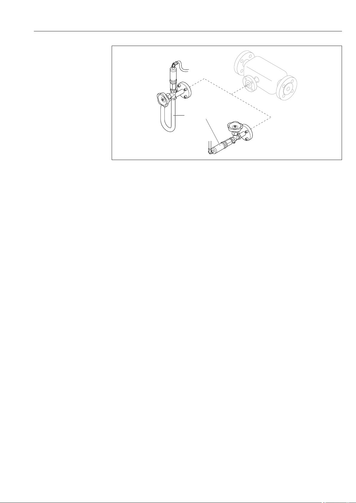
Proline Prowirl F 200 HART Product description
Endress+Hauser 13
A0034152
2 Versions of pressure measuring unit
1 Order code for «Sensor version», option DA «mass steam»
2 Order code for «Sensor version», option DB «mass gas/liquid»
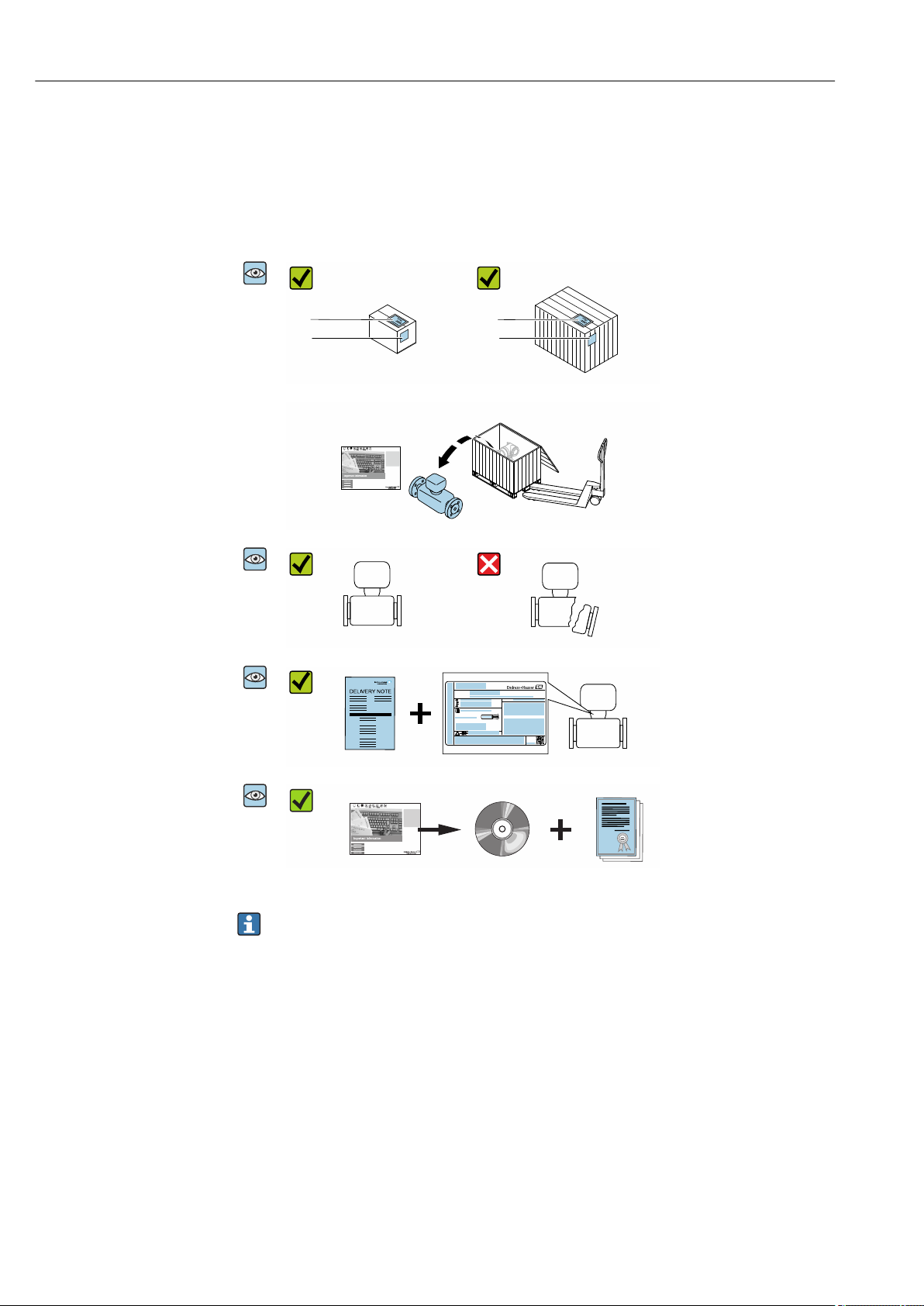
Incoming acceptance and product identification Proline Prowirl F 200 HART
14 Endress+Hauser
4 Incoming acceptance and product
identification
4.1 Incoming acceptance
Are the order codes on the
delivery note (1) and the
product sticker (2) identical?
Are the goods undamaged?
Order code:
Ser. no.:
Ext. ord. cd.:
i
i
Date:
Do the nameplate data
match the ordering
information on the delivery
note?
Is the document folder
present with accompanying
documents?
Is the optional CD-ROM with
the Technical
Documentation present?
• If one of the conditions is not satisfied, contact your Endress+Hauser Sales Center.
• Depending on the device version, the CD-ROM might not be part of the delivery!
The Technical Documentation is available via the Internet or via the Endress+Hauser
Operations App, see the «Product identification» section → 15.
4.2 Product identification
The following options are available for identification of the device:
• Nameplate specifications
• Order code with breakdown of the device features on the delivery note
• Enter serial numbers from nameplates in the W@M Device Viewer
(www.endress.com/deviceviewer): All information about the device is displayed.
• Enter the serial number from nameplates in the Endress+Hauser Operations App or scan
the 2-D matrix code (QR code) on the nameplate using the Endress+Hauser Operations
App: All information about the device is displayed.
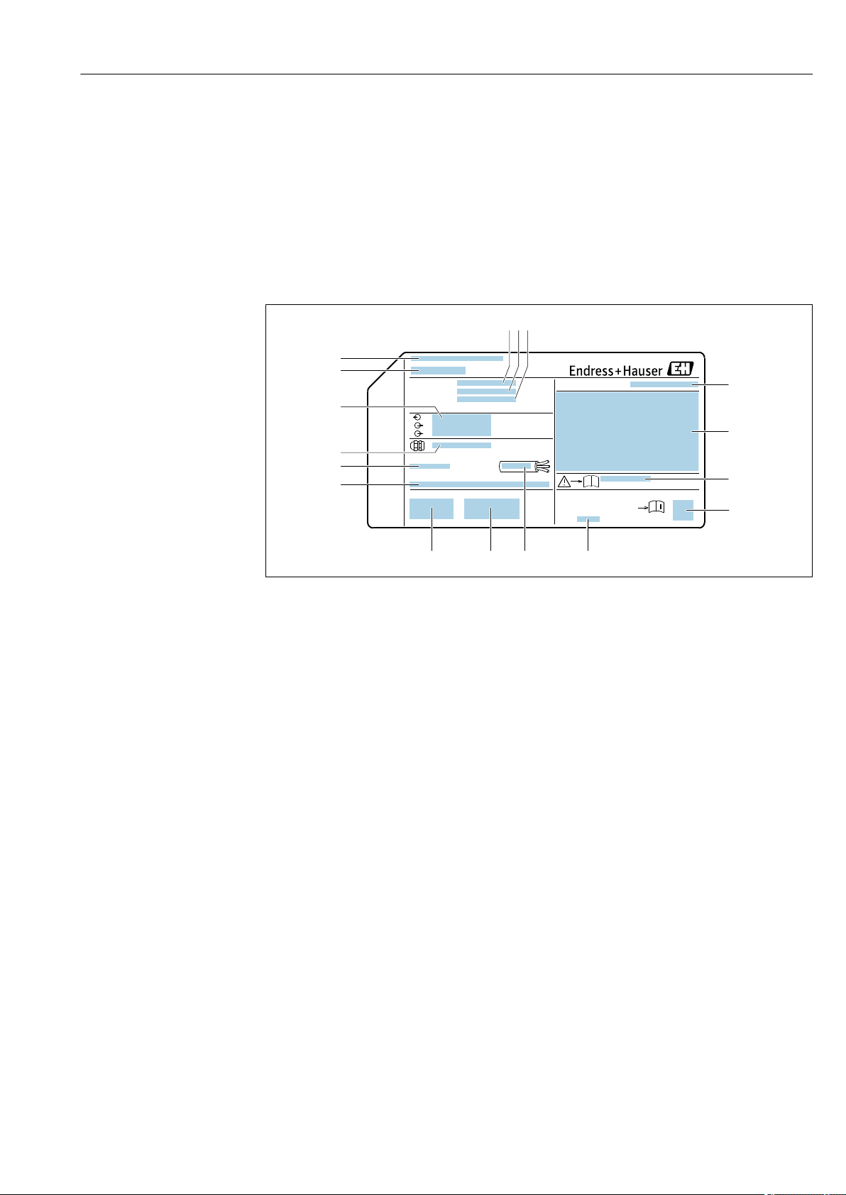
Proline Prowirl F 200 HART Incoming acceptance and product identification
Endress+Hauser 15
For an overview of the scope of the associated Technical Documentation, refer to the
following:
• The «Additional standard documentation on the device»→ 8 and «Supplementary
device-dependent documentation»→ 8 sections
• The W@M Device Viewer: enter the serial number from the nameplate
(www.endress.com/deviceviewer)
• The Endress+Hauser Operations App: Enter the serial number from the nameplate or
scan the 2-D matrix code (QR code) on the nameplate.
4.2.1 Transmitter nameplate
Order code:
Ext. ord. cd.:
Ser. no.:
Date:
i
i
Patents
322540-0001
1
2
3 4 5
6
7
8
9
10 11
12
14
15
16
17
13
A0032237
3 Example of a transmitter nameplate
1 Manufacturing location
2 Name of the transmitter
3 Order code
4 Serial number (ser. no.)
5 Extended order code (Ext. ord. cd.)
6 Electrical connection data, e.g. available inputs and outputs, supply voltage
7 Type of cable glands
8 Permitted ambient temperature (T
a
)
9 Firmware version (FW) and device revision (Dev.Rev.) from the factory
10 CE mark, C-Tick
11 Additional information on version: certificates, approvals
12 Permitted temperature range for cable
13 Manufacturing date: year-month
14 Degree of protection
15 Approval information for explosion protection
16 Document number of safety-related supplementary documentation
17 2-D matrix code
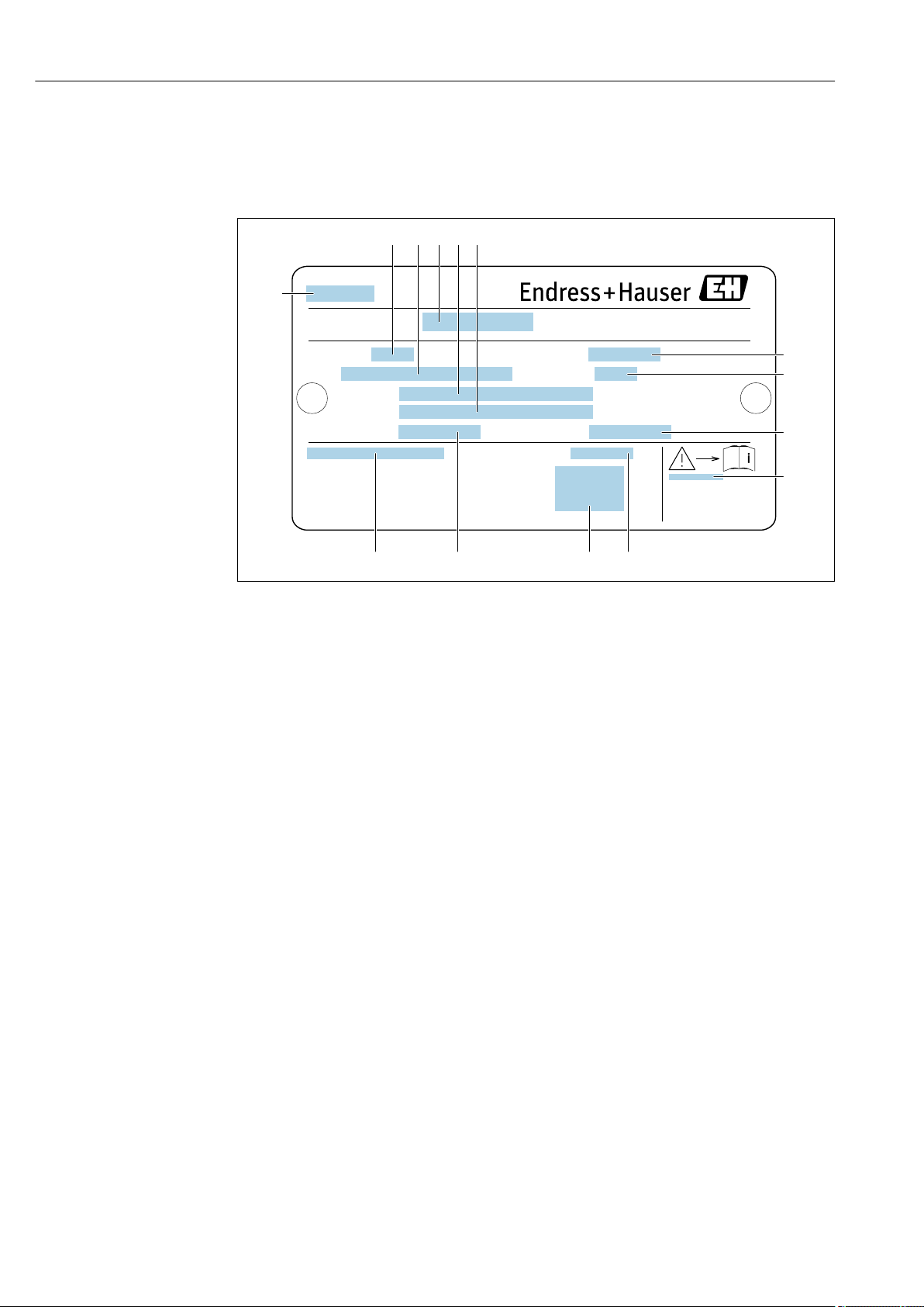
Incoming acceptance and product identification Proline Prowirl F 200 HART
16 Endress+Hauser
4.2.2 Sensor nameplate
Order code for «Housing» option B «GT18 dual compartment, 316L, compact» and
option K «GT18 dual compartment, 316L, remote»
Ser. no.:
Ptest:
Size:
Materials:
Gasket:
Tm:
Qmax(G):
Ta:
1
2 6
7
8
3
9
10
13 12
4 5
14 11
A0034423
4 Example of a sensor nameplate
1 Name of the sensor
2 Nominal diameter of sensor
3 Flange nominal diameter/nominal pressure
4 Serial number (ser. no.)
5 Measuring tube material
6 Measuring tube material
7 Maximum permitted volume flow (gas/steam): Q
max
→ 173
8 Test pressure of the sensor: OPL→ 192
9 Seal material
10 Document number of safety-related supplementary documentation → 205
11 Ambient temperature range
12 CE mark
13 Medium temperature range
14 Degree of protection

Proline Prowirl F 200 HART Incoming acceptance and product identification
Endress+Hauser 17
Order code for «Housing» option C «GT20 dual compartment, aluminum, coated,
compact»
Ser. no.:
Ptest:
Size:
Materials:
Tm:
Qmax(G):
Gasket:
Ta:
1
2
5 6 8
7
9
3
4
10
111213
A0034161
5 Example of a sensor nameplate
1 Nominal diameter of sensor
2 Flange nominal diameter/nominal pressure
3 Measuring tube material
4 Measuring tube material
5 Serial number (ser. no.)
6 Maximal permitted volume flow (gas/steam)
7 Test pressure of the sensor
8 Degree of protection
9 Approval information for explosion protection and Pressure Equipment Directive→ 205
10 CE mark
11 Seal material
12 Medium temperature range
13 Ambient temperature range
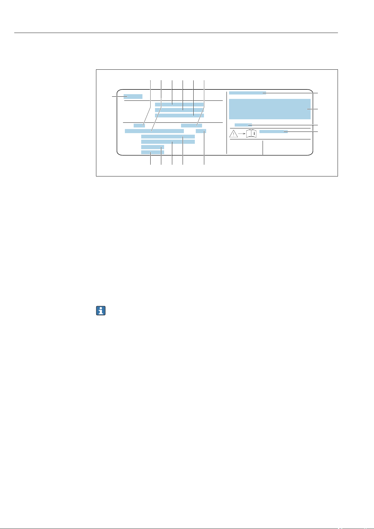
Incoming acceptance and product identification Proline Prowirl F 200 HART
18 Endress+Hauser
Order code for «Housing» option J «GT20 dual compartment, aluminum, coated,
remote»
Order code:
Ext. ord. cd.:
Ser. no.:
Ptest:
Size:
Ta:
Materials:
Gasket:
Tm:
Qmax(G):
4
1
5
8
12
2
7
9
10
11
13141516
3
6
A0034162
6 Example of a sensor nameplate
1 Name of the sensor
2 Nominal diameter of sensor
3 Flange nominal diameter/nominal pressure
4 Order code
5 Serial number (ser. no.)
6 Extended order code (Ext. ord. cd.)
7 Maximal permitted volume flow (gas/steam)
8 Degree of protection
9 Approval information for explosion protection and Pressure Equipment Directive
10 Ambient temperature range
11 Document number of safety-related supplementary documentation → 205
12 Test pressure of the sensor
13 Measuring tube material
14 Measuring tube material
15 Seal material
16 Medium temperature range
Order code
The measuring device is reordered using the order code.
Extended order code
• The device type (product root) and basic specifications (mandatory features) are
always listed.
• Of the optional specifications (optional features), only the safety and approval-
related specifications are listed (e.g. LA). If other optional specifications are also
ordered, these are indicated collectively using the # placeholder symbol (e.g. #LA#).
• If the ordered optional specifications do not include any safety and approval-related
specifications, they are indicated by the + placeholder symbol (e.g. XXXXXX-ABCDE
+).

Proline Prowirl F 200 HART Incoming acceptance and product identification
Endress+Hauser 19
4.2.3 Pressure measuring cells nameplate
A0034354
7 Example of pressure measuring cell nameplate
1 Manufacturer address
2 Pressure range
3 Maximum permitted pressure
4 Ambient temperature range
5 Serial number or XPD structure
6 Degree of protection
7 CE mark, C-Tick mark
8 QR code
9 Manufacturing date
4.2.4 Symbols on measuring device
Symbol Meaning
WARNING!
This symbol alerts you to a dangerous situation. Failure to avoid this situation can result in serious
or fatal injury.
Reference to documentation
Refers to the corresponding device documentation.
Protective ground connection
A terminal which must be connected to ground prior to establishing any other connections.

Storage and transport Proline Prowirl F 200 HART
20 Endress+Hauser
5 Storage and transport
5.1 Storage conditions
Observe the following notes for storage:
‣
Store in the original packaging to ensure protection from shock.
‣
Do not remove protective covers or protective caps installed on process connections.
They prevent mechanical damage to the sealing surfaces and contamination in the
measuring tube.
‣
Protect from direct sunlight to avoid unacceptably high surface temperatures.
‣
Store in a dry and dust-free place.
‣
Do not store outdoors.
Storage temperature: –50 to +80 °C (–58 to +176 °F)
5.2 Transporting the product
Transport the measuring device to the measuring point in the original packaging.
A0029252
Do not remove protective covers or caps installed on process connections. They
prevent mechanical damage to the sealing surfaces and contamination in the
measuring tube.
5.2.1 Measuring devices without lifting lugs
L
WARNING
Center of gravity of the measuring device is higher than the suspension points of the
webbing slings.
Risk of injury if the measuring device slips.
‣
Secure the measuring device against slipping or turning.
‣
Observe the weight specified on the packaging (stick-on label).
A0029214

Proline Prowirl F 200 HART Storage and transport
Endress+Hauser 21
5.2.2 Measuring devices with lifting lugs
L
CAUTION
Special transportation instructions for devices with lifting lugs
‣
Only use the lifting lugs fitted on the device or flanges to transport the device.
‣
The device must always be secured at two lifting lugs at least.
5.2.3 Transporting with a fork lift
If transporting in wood crates, the floor structure enables the crates to be lifted lengthwise
or at both sides using a forklift.
5.3 Packaging disposal
All packaging materials are environmentally friendly and 100 % recyclable:
• Outer packaging of device
Polymer stretch wrap that complies with EU Directive 2002/95/EC (RoHS)
• Packaging
• Wooden crate treated in accordance with ISPM 15 standard, confirmed by IPPC logo
• Cardboard box in accordance with European packaging guideline 94/62EC,
recyclability confirmed by Resy symbol
• Carrying and securing materials
• Disposable plastic pallet
• Plastic straps
• Plastic adhesive strips
• Filler material
Paper pads
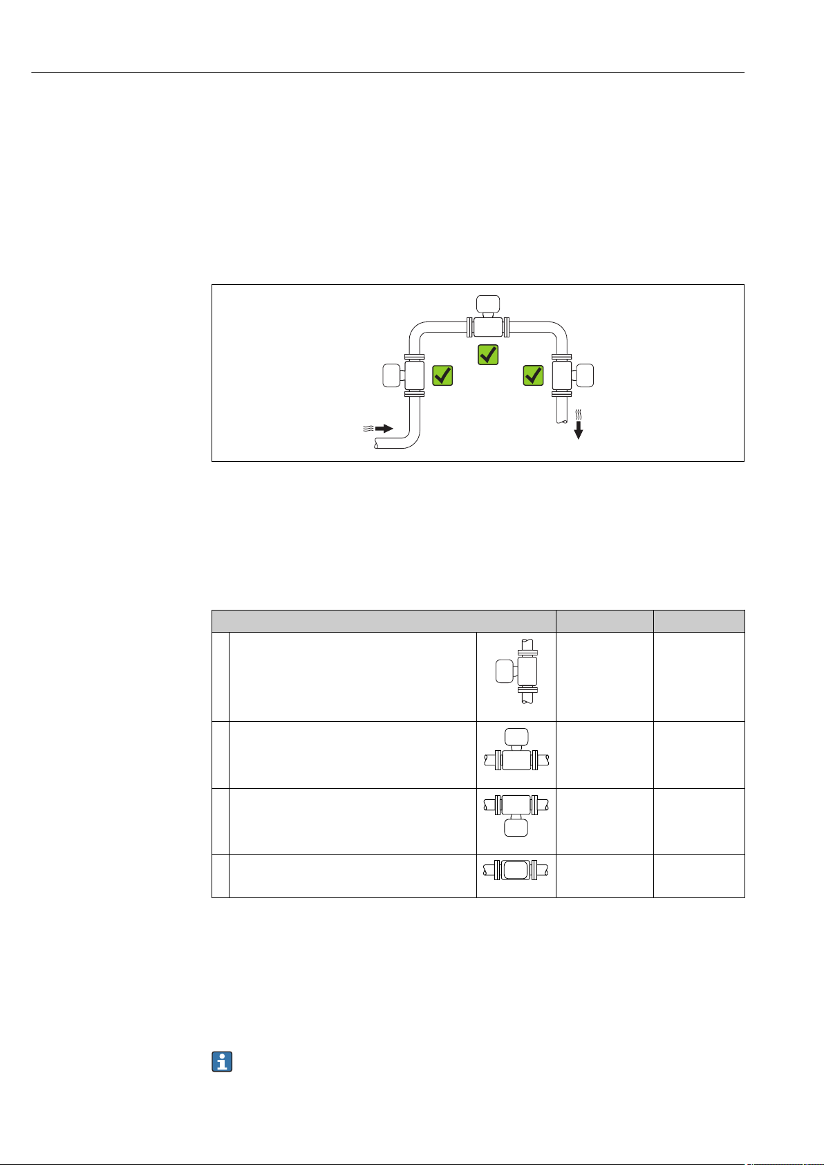
Installation Proline Prowirl F 200 HART
22 Endress+Hauser
6 Installation
6.1 Installation conditions
6.1.1 Mounting position
Mounting location
A0015543
Orientation
The direction of the arrow on the sensor nameplate helps you to install the sensor
according to the flow direction (direction of medium flow through the piping).
Vortex meters require a fully developed flow profile as a prerequisite for correct volume
flow measurement. Therefore, please note the following:
Orientation Compact version Remote version
A Vertical orientation
A0015545
1)
B Horizontal orientation, transmitter head up
A0015589
2) 3)
C Horizontal orientation, transmitter head down
A0015590
4) 5)
D Horizontal orientation, transmitter head at side
A0015592
4)
1) In the case of liquids, there should be upward flow in vertical pipes to avoid partial pipe filling (Fig. A).
Disruption in flow measurement! In the case of vertical orientation and downward flowing liquid, the pipe
always needs to be completely filled to ensure correct liquid flow measurement.
2) Danger of electronics overheating! If the fluid temperature is ≥ 200 °C (392 °F), orientation B is not
permitted for the wafer version (Prowirl D) with nominal diameters of DN 100 (4″) and DN 150 (6″).
3) In the case of hot media (e.g. steam or fluid temperature (TM) ≥ 200 °C (392 °F): orientation C or D
4) In the case of very cold media (e.g. liquid nitrogen): orientation B or D
5) For «wet steam detection/measurement» option: orientation C
The «mass» sensor version (integrated pressure/temperature measurement) is
available only for measuring devices in the HART communication mode.

Proline Prowirl F 200 HART Installation
Endress+Hauser 23
Pressure measuring cell
Steam pressure measurement Option DA
E • With the
transmitter
installed at the
bottom or at the
side
• Protection
against rising
heat
• Reduction in
temperature to
almost ambient
temperature due
to siphon
1)
A0034057
F
A0034058
Gas pressure measurement Option DB
G • Pressure
measuring cell
with shutoff
device above
tapping point
• Discharge of any
condensate into
the process
A0034092
Liquid pressure measurement Option DB
H Device with shutoff
device at the same
level as tapping
point
A0034091
1) Note max. permitted ambient temperature of transmitter→ 27.
Minimum spacing and cable length
Order code for «Sensor version», option «mass» DA, DB
The «mass» sensor version (integrated pressure/temperature measurement) is
available only for measuring devices in the HART communication mode.
A0019211
A Minimum spacing in all directions
L Required cable length

Installation Proline Prowirl F 200 HART
24 Endress+Hauser
The following dimensions must be observed to guarantee problem-free access to the device
for service purposes:
• A =100 mm (3.94 in)
• L = L + 150 mm (5.91 in)
Inlet and outlet runs
To attain the specified level of accuracy of the measuring device, the inlet and outlet runs
mentioned below must be maintained at the very minimum.
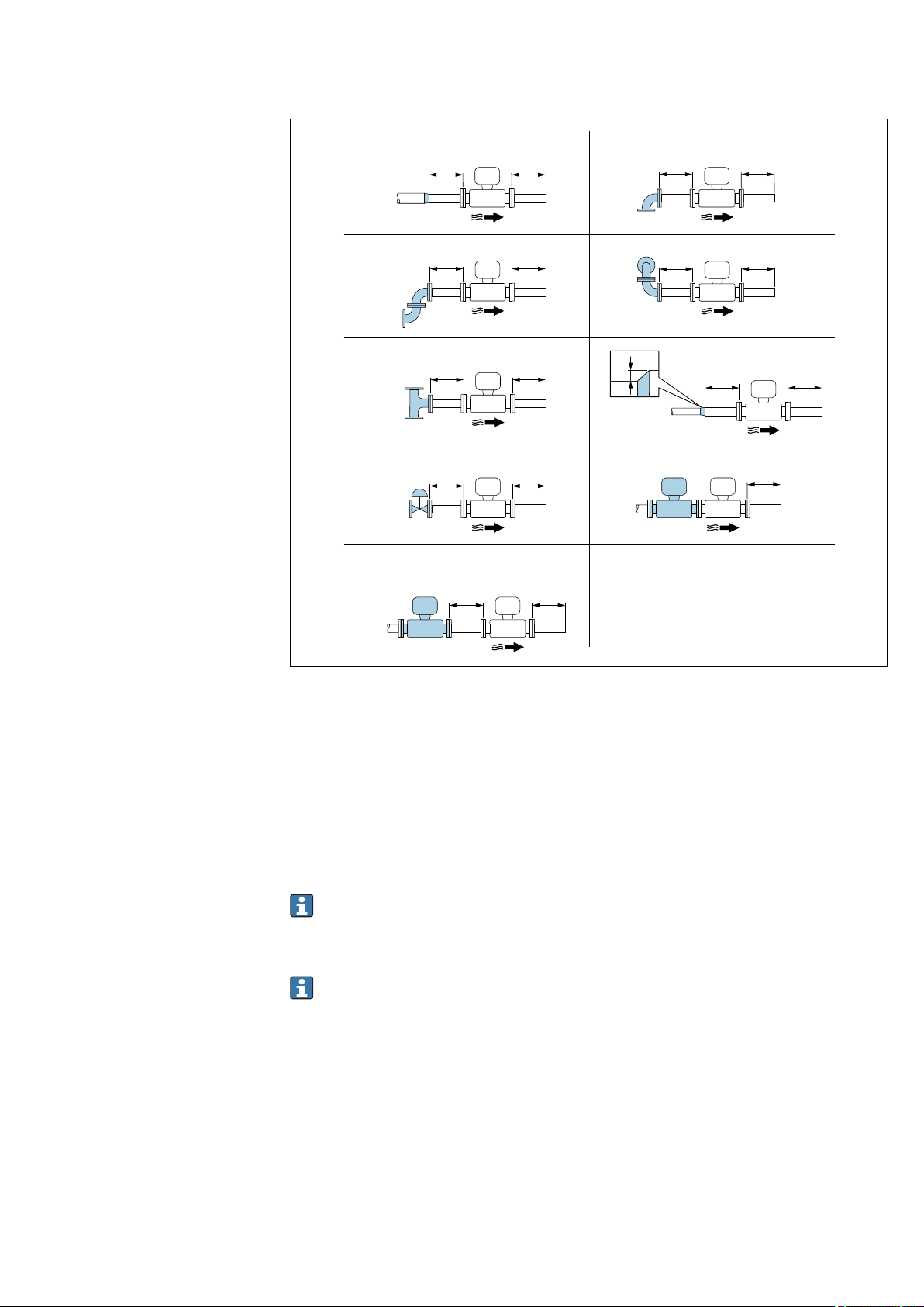
Proline Prowirl F 200 HART Installation
Endress+Hauser 25
1
15 DN×
5 × DN
3
25 × DN
5 × DN
40 × DN
5 × DN
4
2
20 × DN
5 × DN
5
20 × DN
5 × DN
6
17 × DN + 8 × h
5 × DN
h
7
50 × DN
5 × DN
9
40 × DN
5 × DN
8
5 × DN
DN 25 (1″):≤
DN 40 (1½»):≥
A0019189
8 Minimum inlet and outlet runs with various flow obstructions
h Difference in expansion
1 Reduction by one nominal diameter size
2 Single elbow (90° elbow)
3 Double elbow (2 × 90° elbows, opposite)
4 Double elbow 3D (2 × 90° elbows, opposite, not on one plane)
5 T-piece
6 Expansion
7 Control valve
8 Two measuring devices in a row where DN ≤ 25 (1″): directly flange on flange
9 Two measuring devices in a row where DN ≥ 40 (1½»): for spacing, see graphic
• If there are several flow disturbances present, the longest specified inlet run must
be maintained.
• If the required inlet runs cannot be observed, it is possible to install a specially
designed flow conditioner → 25.
The inlet run correction function:
• Makes it possible to shorten the inlet run to a minimum length of 10 × DN in the
event of flow obstructions 1 to 4. An additional measuring uncertainty of ±0.5% o.r.
occurs here. → 111
• Cannot be combined with the wet steam detection/measurement application
package. If wet steam detection/measurement is used, the corresponding inlet runs
must be taken into consideration. It is not possible to use a flow conditioner for wet
steam.
Flow conditioner
If the inlet runs cannot be observed, the use of a flow conditioner is recommended.
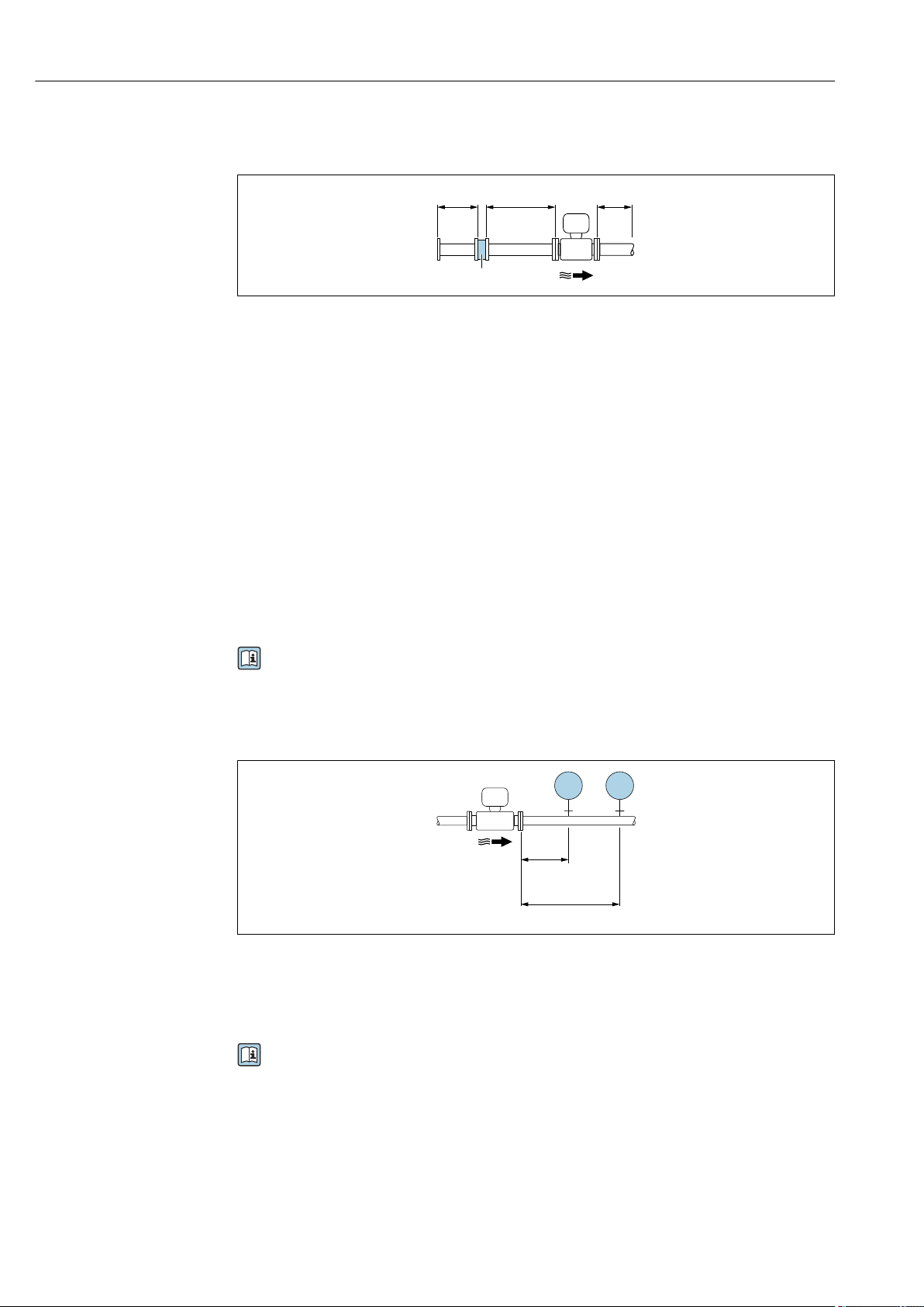
Installation Proline Prowirl F 200 HART
26 Endress+Hauser
The flow conditioner is fitted between two pipe flanges and centered by the mounting
bolts. Generally this reduces the inlet run needed to 10 × DN with full accuracy.
A0019208
1 Flow conditioner
The pressure loss for flow conditioners is calculated as follows: ∆ p [mbar] = 0.0085 ⋅ ρ
[kg/m
3
] ⋅ v
2
[m/s]
Example for steam Example for H
2
O condensate (80 °C)
p = 10 bar abs. ρ = 965 kg/m
3
t = 240 °C → ρ = 4.39 kg/m
3
v = 2.5 m/s
v = 40 m/s ∆ p = 0.0085 ⋅ 965 ⋅ 2.5
2
= 51.3 mbar
∆ p = 0.0085 ⋅ 4.394.39 ⋅ 40
2
= 59.7 mbar
ρ : density of the process medium
v: average flow velocity
abs. = absolute
For the dimensions of the flow conditioner, see the «Technical Information» document,
«Mechanical construction» section
Outlet runs when installing external devices
If installing an external device, observe the specified distance.
A0019205
PT Pressure
TT Temperature device
Installation dimensions
For the dimensions and installation lengths of the device, see the «Technical
Information» document, «Mechanical construction» section.

Proline Prowirl F 200 HART Installation
Endress+Hauser 27
6.1.2 Environment and process requirements
Ambient temperature range
Compact version
Measuring device Non-hazardous area: –40 to +80 °C (–40 to +176 °F)
1)
Ex i, Ex nA, Ex ec: –40 to +70 °C (–40 to +158 °F)
1)
Ex d, XP: –40 to +60 °C (–40 to +140 °F)
1)
Ex d, Ex ia: –40 to +60 °C (–40 to +140 °F)
1)
Local display –40 to +70 °C (–40 to +158 °F)
2) 1)
1) Additionally available as order code for «Test, certificate», option JN «Transmitter ambient temperature –
50 °C (–58 °F)».
2) At temperatures < –20 °C (–4 °F), depending on the physical characteristics involved, it may no longer be
possible to read the liquid crystal display.
Remote version
Transmitter Non-hazardous area: –40 to +80 °C (–40 to +176 °F)
1)
Ex i, Ex nA, Ex ec: –40 to +80 °C (–40 to +176 °F)
1)
Ex d: –40 to +60 °C (–40 to +140 °F)
1)
Ex d, Ex ia: –40 to +60 °C (–40 to +140 °F)
1)
Sensor Non-hazardous area: –40 to +85 °C (–40 to +185 °F)
1)
Ex i, Ex nA, Ex ec: –40 to +85 °C (–40 to +185 °F)
1)
Ex d: –40 to +85 °C (–40 to +185 °F)
1)
Ex d, Ex ia: –40 to +85 °C (–40 to +185 °F)
1)
Local display –40 to +70 °C (–40 to +158 °F)
2) 1)
1) Additionally available as order code for «Test, certificate», option JN «Transmitter ambient temperature –
50 °C (–58 °F)».
2) At temperatures < –20 °C (–4 °F), depending on the physical characteristics involved, it may no longer be
possible to read the liquid crystal display.
‣
If operating outdoors:
Avoid direct sunlight, particularly in warm climatic regions.
You can order a weather protection cover from Endress+Hauser. → 168.
Thermal insulation
For optimum temperature measurement and mass calculation, heat transfer at the sensor
must be avoided for some fluids. This can be ensured by installing thermal insulation. A
wide range of materials can be used for the required insulation.
This applies for:
• Compact version
• Remote sensor version
The maximum insulation height permitted is illustrated in the diagram:
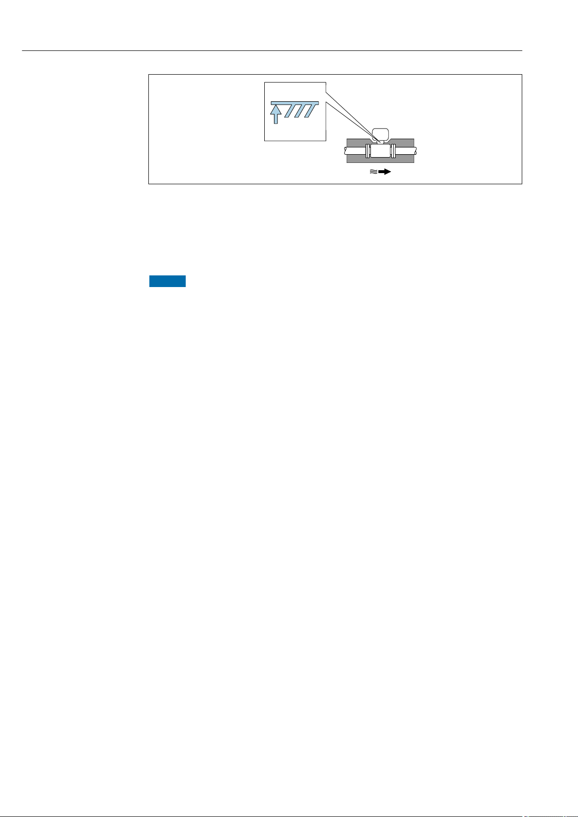
Installation Proline Prowirl F 200 HART
28 Endress+Hauser
A0019212
1 Maximum insulation height
‣
When insulating, ensure that a sufficiently large area of the housing support remains
exposed.
The uncovered part serves as a radiator and protects the electronics from overheating and
excessive cooling.
NOTICE
Electronics overheating on account of thermal insulation!
‣
Observe the maximum permitted insulation height of the transmitter neck so that the
transmitter head and/or the connection housing of the remote version is completely
free.
‣
Observe information on the permissible temperature ranges.
‣
Note that a certain orientation might be required, depending on the fluid temperature.
6.1.3 Special mounting instructions
Installation for delta heat measurements
• Order code for «Sensor version», option CA «mass; 316L; 316L (integrated temperature
measurement), –200 to +400 °C (–328 to +750 °F)»
• Order code for «Sensor version», option CB «mass; Alloy C22; 316L (integrated
temperature measurement), –200 to +400 °C (–328 to +750 °F)»
• Order code for «Sensor version», option CC «mass; Alloy C22; Alloy C22 (integrated
temperature measurement), –40 to +260 °C (–40 to +500 °F)»
• Order code for «Sensor version», option DA «mass steam; 316L; 316L (integrated
pressure/temperature measurement), –200 to +400 °C (–328 to +750 °F)»
• Order code for «Sensor version», option DB «mass gas/liquid; 316L; 316L (integrated
pressure/temperature measurement), –40 to +100 °C (–40 to +212 °F)»
The second temperature measurement is taken using a separate temperature sensor. The
measuring device reads in this value via a communication interface.
• In the case of saturated steam delta heat measurements, the measuring device must be
installed on the steam side.
• In the case of water delta heat measurements, the device can be installed on the cold or
warm side.
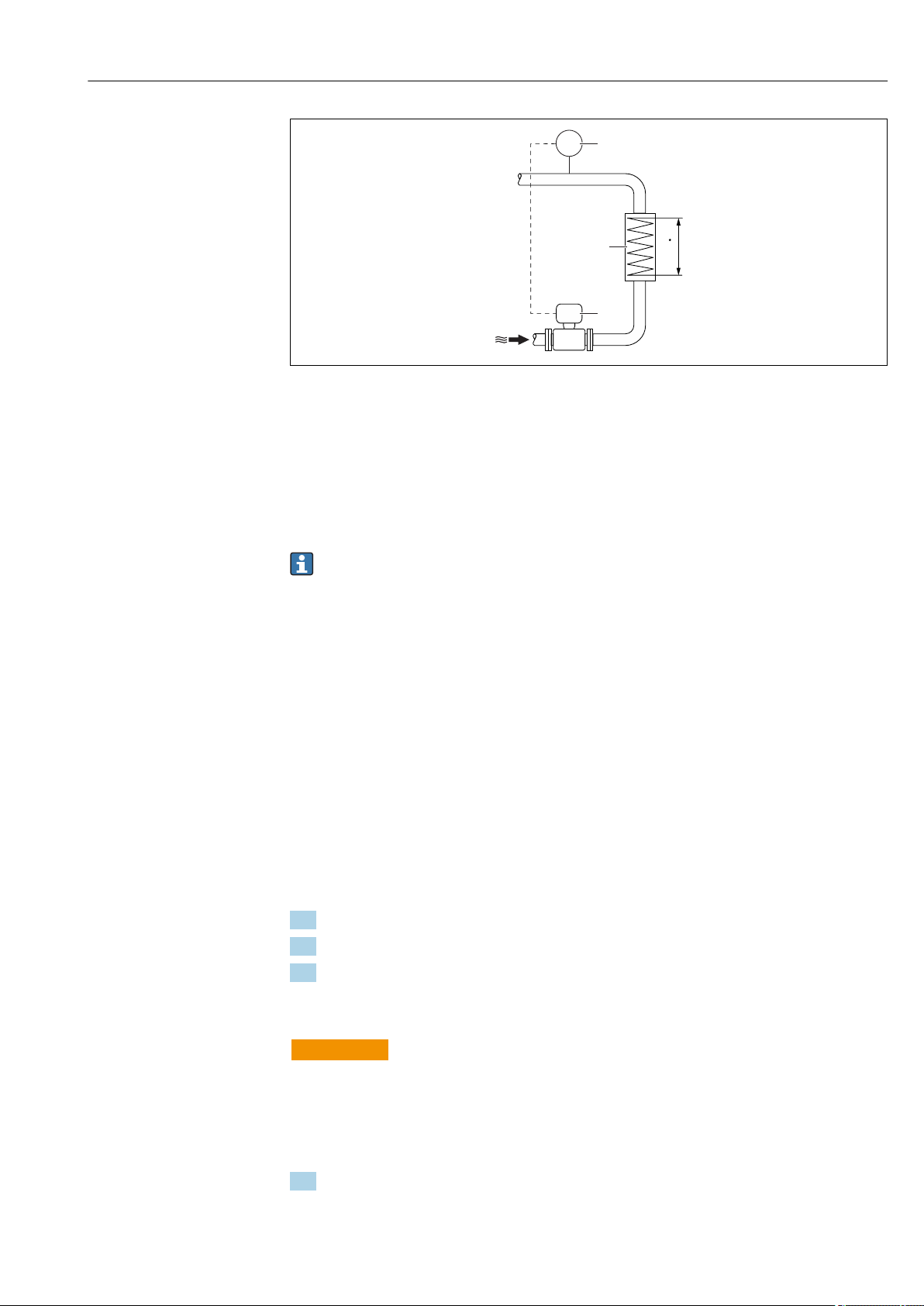
Proline Prowirl F 200 HART Installation
Endress+Hauser 29
A0019209
9 Layout for delta heat measurement of saturated steam and water
1 Measuring device
2 Temperature sensor
3 Heat exchanger
Q Heat flow
Protective cover
Observe the following minimum head clearance: 222 mm (8.74 in)
For information on the weather protection cover, see → 168
6.2 Mounting the measuring device
6.2.1 Required tools
For transmitter
• For turning the transmitter housing: Open-ended wrench8 mm
• For opening the securing clamps: Allen key3 mm
For sensor
For flanges and other process connections: Corresponding mounting tools
6.2.2 Preparing the measuring device
1. Remove all remaining transport packaging.
2. Remove any protective covers or protective caps present from the sensor.
3. Remove stick-on label on the electronics compartment cover.
6.2.3 Mounting the sensor
L
WARNING
Danger due to improper process sealing!
‣
Ensure that the inside diameters of the gaskets are greater than or equal to that of the
process connections and piping.
‣
Ensure that the gaskets are clean and undamaged.
‣
Install the gaskets correctly.
1. Ensure that the direction of the arrow on the sensor matches the flow direction of
the medium.
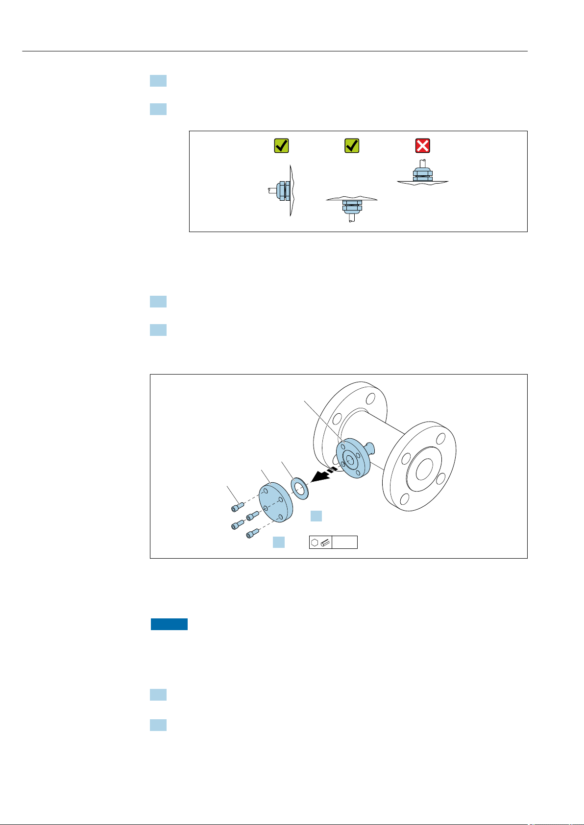
Installation Proline Prowirl F 200 HART
30 Endress+Hauser
2. To ensure compliance with device specifications, install the measuring device
between the pipe flanges in a way that it is centered in the measurement section.
3. Install the measuring device or turn the transmitter housing so that the cable entries
do not point upwards.
A0029263
6.2.4 Mounting the pressure measuring unit
Preparation
1. Prior to mounting the pressure measuring unit, install the measuring device in the
pipe.
2. When mounting the pressure measuring unit, use only the seal provided. The use of a
different sealing material is not permitted.
Removing the blind flange
A0034355
1 Mounting screws
2 blind flange
3 Seal
4 Flange connection on sensor side
NOTICE
When replacing the seal following commissioning, fluid may escape when the flange
connection is opened!
‣
Ensure that the measuring device is not under pressure.
‣
Ensure that there is no fluid in the measuring device.
1. Release the mounting screws on the blind flange.
The screws are needed again to mount the pressure measuring unit.
2. Remove the internal seal.
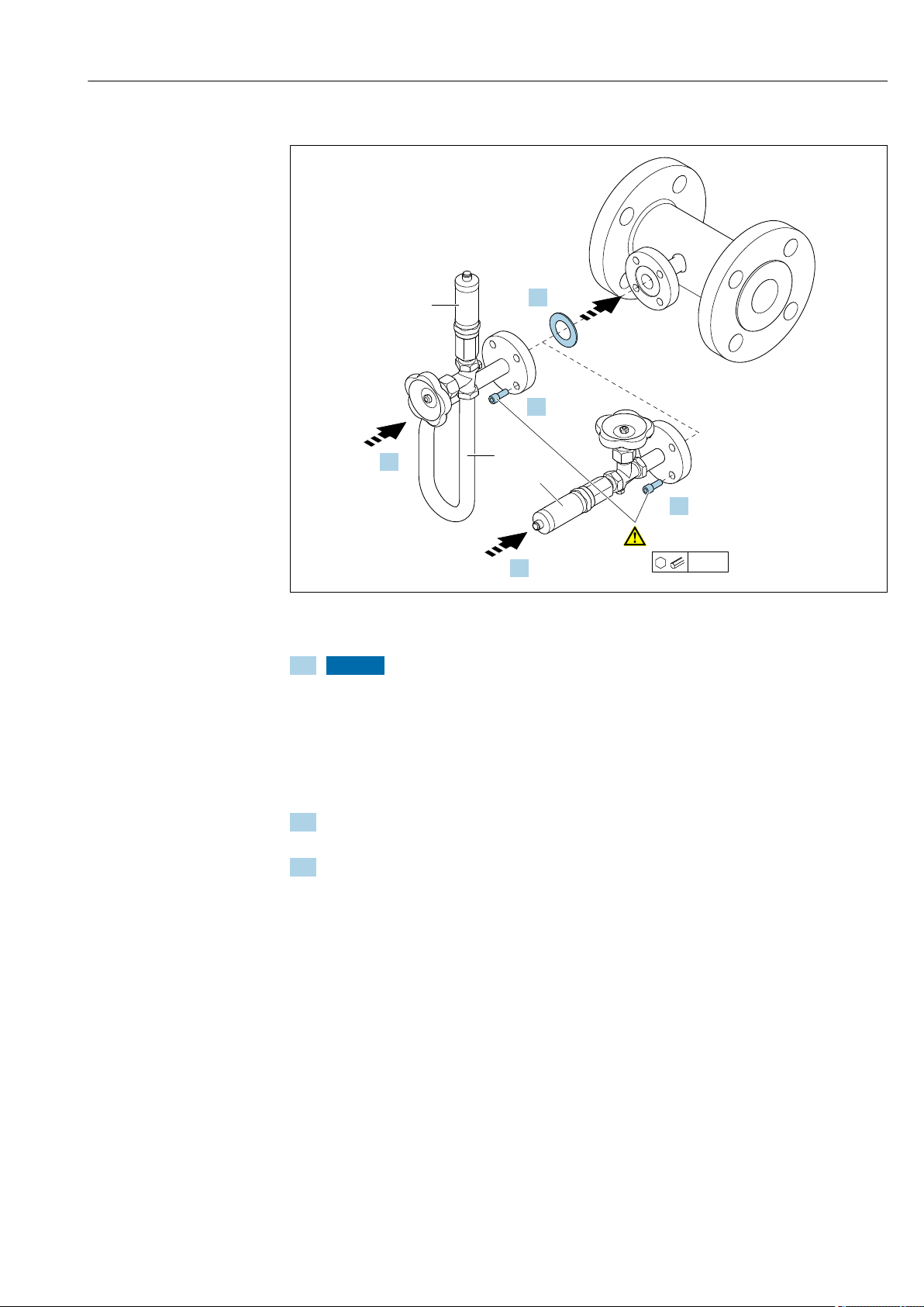
Proline Prowirl F 200 HART Installation
Endress+Hauser 31
Mounting the pressure measuring unit
A0035442
5 Siphon
6 Pressure measuring cell
3. NOTICE
Damage to seal!
The seal is made of expanded graphite. It can therefore be used only once. If a
coupling is released, a new seal must be installed.
‣
Use the additional seals provided. If necessary, these can be ordered as separate
spare parts at a later stage.
Insert the enclosed seal into the groove of the flange connection on the sensor side.
4. Align the flange connection on the pressure measuring unit and tighten the screws
by hand.
5. Tighten the screws with a torque wrench in three steps.
1. 10 Nm in criss-cross sequence
2. 15 Nm in criss-cross sequence
3. 15 Nm in circular sequence
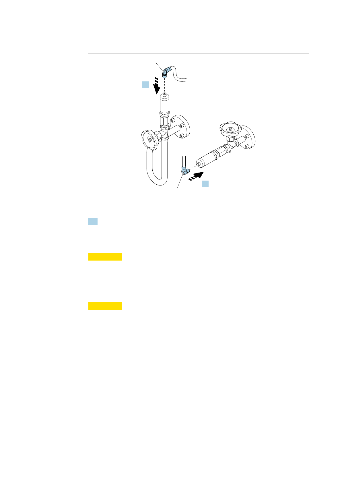
Installation Proline Prowirl F 200 HART
32 Endress+Hauser
Connecting the pressure measuring unit
A0035443
7 Device plug
6. Insert the plug for electrical connection of the pressure measuring cell and screw into
place.
6.2.5 Mounting the transmitter of the remote version
L
CAUTION
Ambient temperature too high!
Danger of electronics overheating and housing deformation.
‣
Do not exceed the permitted maximum ambient temperature .
‣
If operating outdoors: Avoid direct sunlight and exposure to weathering, particularly in
warm climatic regions.
L
CAUTION
Excessive force can damage the housing!
‣
Avoid excessive mechanical stress.
The transmitter of the remote version can be mounted in the following ways:
• Wall mounting
• Pipe mounting
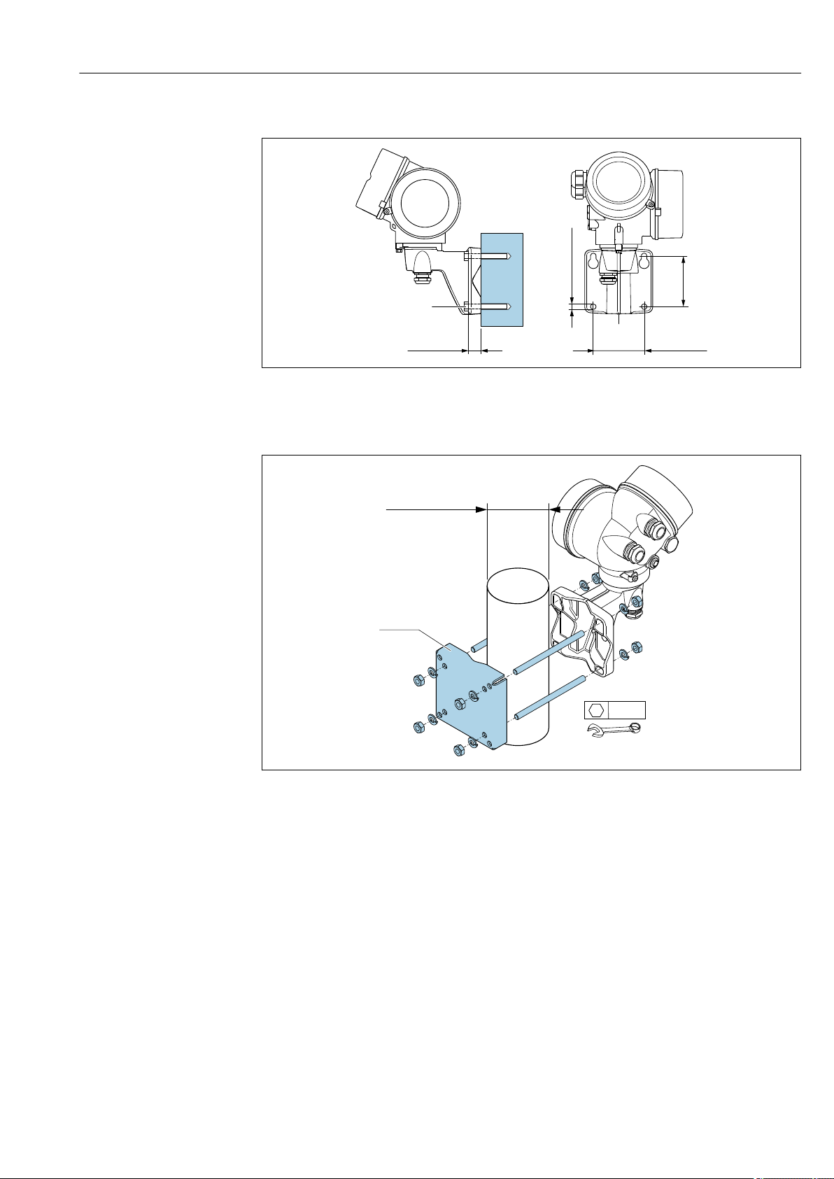
Proline Prowirl F 200 HART Installation
Endress+Hauser 33
Wall mounting
80 (3.15)
80 (3.15)
19 (0.6)
! 8.6 (0.39)
M8
A0033484
10 mm (in)
Post mounting
! …20 70
(! 0.79 to 2.75)
4 x
SW 13
A0033486
11 mm (in)
6.2.6 Turning the transmitter housing
To provide easier access to the connection compartment or display module, the transmitter
housing can be turned.
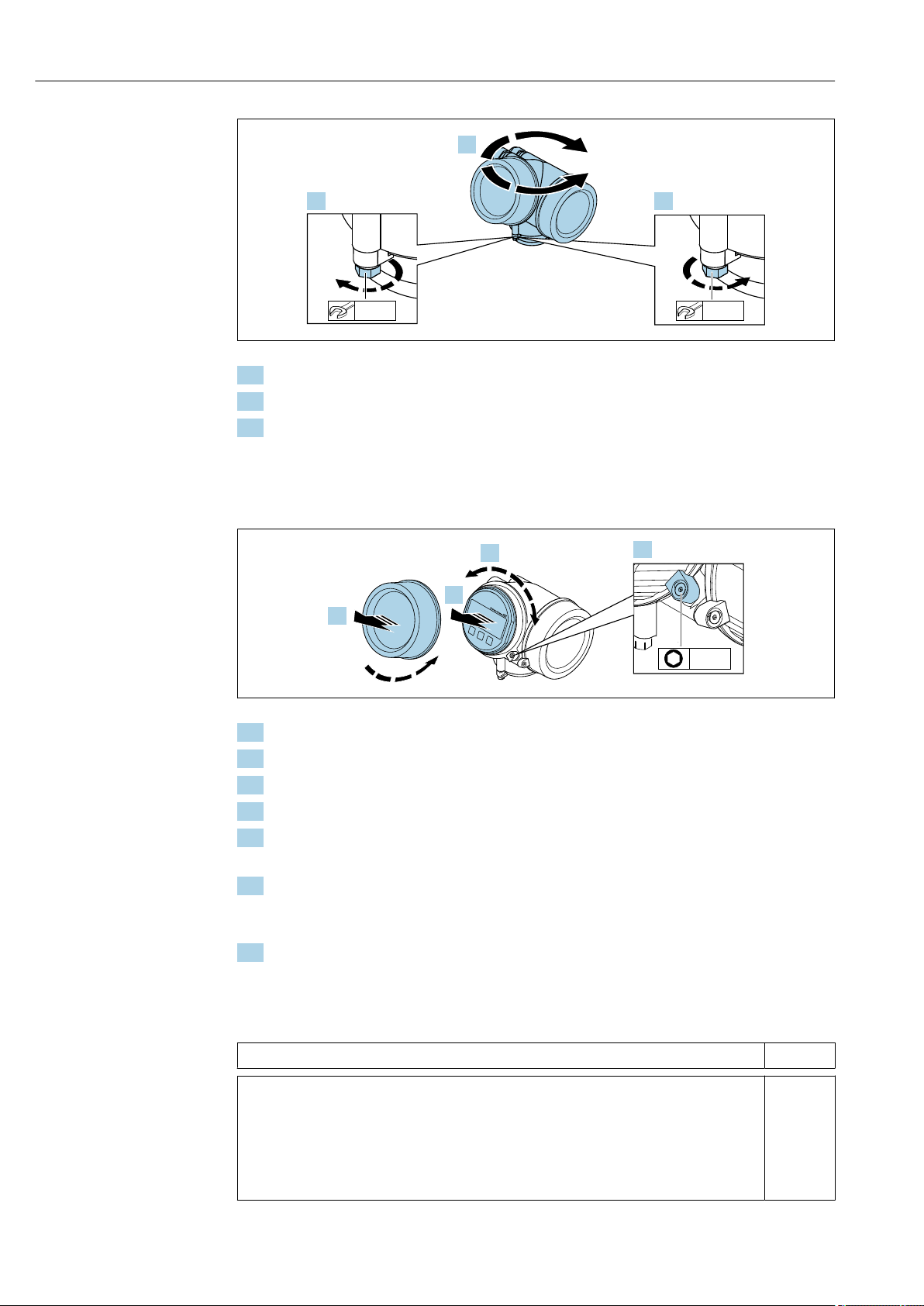
Installation Proline Prowirl F 200 HART
34 Endress+Hauser
A0032242
1. Release the fixing screw.
2. Turn the housing to the desired position.
3. Firmly tighten the securing screw.
6.2.7 Turning the display module
The display module can be turned to optimize display readability and operability.
A0032238
1. Loosen the securing clamp of the electronics compartment cover using an Allen key.
2. Unscrew cover of the electronics compartment from the transmitter housing.
3. Optional: pull out the display module with a gentle rotational movement.
4. Turn the display module to the desired position: max. 8 × 45° in every direction.
5. Without display module pulled out:
Allow display module to engage at desired position.
6. With display module pulled out:
Feed the cable into the gap between the housing and main electronics module and
plug the display module into the electronics compartment until it engages.
7. Reverse the removal procedure to reassemble the transmitter.
6.3 Post-installation check
Is the device undamaged (visual inspection)?
Does the measuring device conform to the measuring point specifications?
For example:
• Process temperature → 191
• Process pressure (refer to the section on «Pressure-temperature ratings» in the «Technical
Information» document → 205)
• Ambient temperature
• Measuring range → 173

Proline Prowirl F 200 HART Installation
Endress+Hauser 35
Has the correct orientation for the sensor been selected → 22?
• According to sensor type
• According to medium temperature
• According to medium properties (outgassing, with entrained solids)
Does the arrow on the sensor nameplate match the direction of flow of the fluid through the
piping → 22?
Are the measuring point identification and labeling correct (visual inspection)?
Is the device adequately protected against precipitation and direct sunlight?
Are the securing screw and securing clamp tightened securely?
Has the maximum permitted insulation height been observed?
• Has the pressure range been observed→ 192?
• Was the correct orientation selected→ 23?
• Is the pressure unit mounted correctly→ 30?
• Have the pressure gauge valve and the siphon with pressure sensor been mounted using the
prescribed seal and the specified torque→ 30?

Electrical connection Proline Prowirl F 200 HART
36 Endress+Hauser
7 Electrical connection
7.1 Connection conditions
7.1.1 Required tools
• For cable entries: Use corresponding tools
• For securing clamp: Allen key 3 mm
• Wire stripper
• When using stranded cables: Crimper for wire end ferrule
• For removing cables from terminal: Flat blade screwdriver ≤ 3 mm (0.12 in)
7.1.2 Connecting cable requirements
The connecting cables provided by the customer must fulfill the following requirements.
Electrical safety
In accordance with applicable federal/national regulations.
Permitted temperature range
• The installation guidelines that apply in the country of installation must be observed.
• The cables must be suitable for the minimum and maximum temperatures to be
expected.
Signal cable
Current output 4 to 20 mA HART
A shielded cable is recommended. Observe grounding concept of the plant.
Current output 4 to 20 mA
Standard installation cable is sufficient.
Pulse/frequency/switch output
Standard installation cable is sufficient.
Current input
Standard installation cable is sufficient.
Cable diameter
• Cable glands supplied:
M20 × 1.5 with cable 6 to 12 mm (0.24 to 0.47 in)
• Plug-in spring terminals for device version without integrated overvoltage protection:
wire cross-sections 0.5 to 2.5 mm
2
(20 to 14 AWG)
• Screw terminals for device version with integrated overvoltage protection: wire cross-
sections 0.2 to 2.5 mm
2
(24 to 14 AWG)

Proline Prowirl F 200 HART Electrical connection
Endress+Hauser 37
7.1.3 Connecting cable for remote version
Connecting cable (standard)
Standard cable
2 × 2 × 0.5 mm
2
(22 AWG) PVC cable with common shield (2 pairs, pair-
stranded)
1)
Flame resistance According to DIN EN 60332-1-2
Oil-resistance According to DIN EN 60811-2-1
Shielding Galvanized copper-braid, opt. density approx.85 %
Cable length 5 m (16 ft), 10 m (32 ft), 20 m (65 ft), 30 m (98 ft)
Operating temperature When mounted in a fixed position: –50 to +105 °C (–58 to +221 °F); when cable
can move freely: –25 to +105 °C (–13 to +221 °F)
1) UV radiation may cause damage to the outer jacket of the cable. Protect the cable from exposure to sun as
much as possible.
Connecting cable (reinforced)
Cable, reinforced
2 × 2 × 0.34 mm
2
(22 AWG) PVC cable with common shield (2 pairs, pair-
stranded) and additional steel-wire braided sheath
1)
Flame resistance According to DIN EN 60332-1-2
Oil-resistance According to DIN EN 60811-2-1
Shielding Galvanized copper-braid, opt. density approx. 85%
Strain relief and
reinforcement
Steel-wire braid, galvanized
Cable length 5 m (16 ft), 10 m (32 ft), 20 m (65 ft), 30 m (98 ft)
Operating temperature When mounted in a fixed position: –50 to +105 °C (–58 to +221 °F); when cable
can move freely: –25 to +105 °C (–13 to +221 °F)
1) UV radiation may cause damage to the outer jacket of the cable. Protect the cable from exposure to sun as
much as possible.
Connecting cable (option «mass pressure-/temperature-compensated»)
Order code for «Sensor version; DSC sensor; measuring tube», option DA, DB
Standard cable
[(3 × 2) + 1] × 0.34 mm
2
(22 AWG)PVC cable with common shield (3 pairs, pair-
stranded)
1)
Flame resistance According to DIN EN 60332-1-2
Oil-resistance According to DIN EN 60811-2-1
Shielding Galvanized copper-braid, opt. density approx. 85%
Cable length 10 m (32 ft), 30 m (98 ft)
Operating temperature When mounted in a fixed position: –50 to +105 °C (–58 to +221 °F); when cable
can move freely: –25 to +105 °C (–13 to +221 °F)
1) UV radiation may cause damage to the outer jacket of the cable. Protect the cable from exposure to sun as
much as possible.
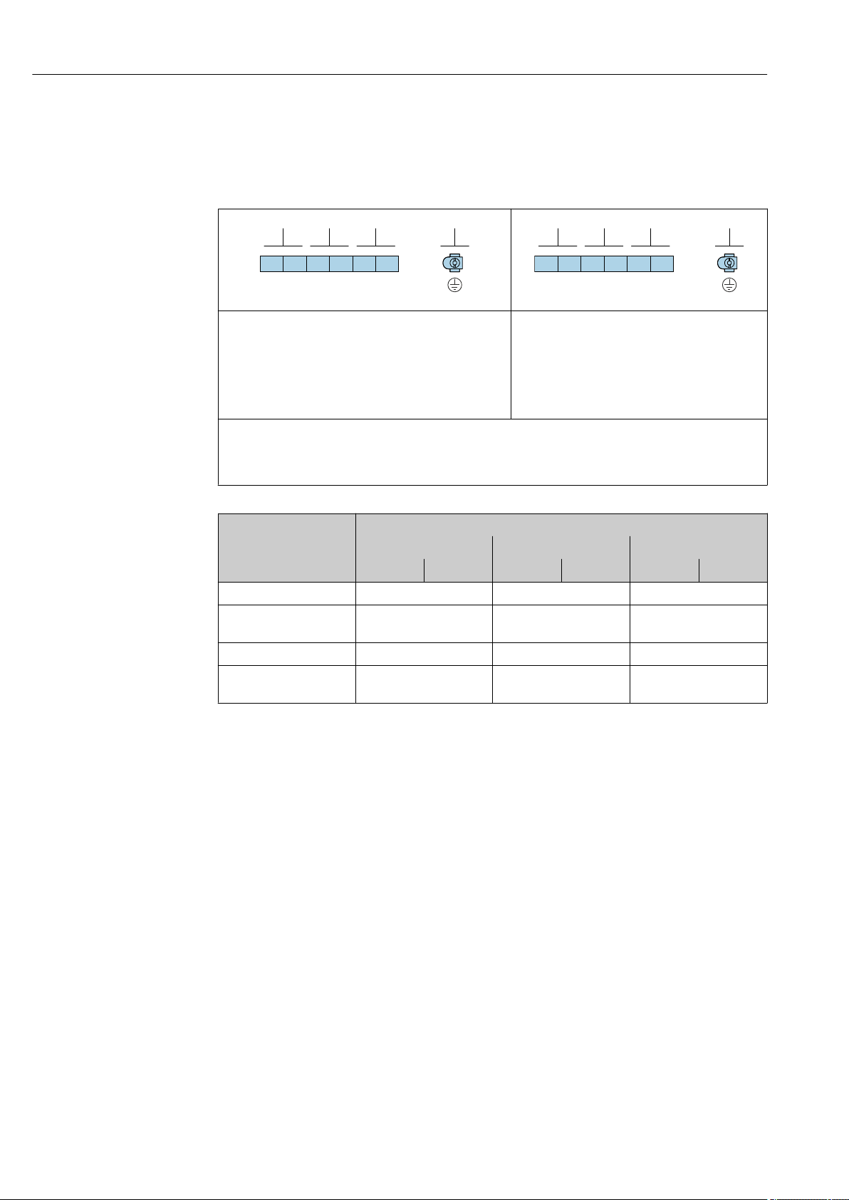
Electrical connection Proline Prowirl F 200 HART
38 Endress+Hauser
7.1.4 Terminal assignment
Transmitter
4-20 mA HART connection version with additional inputs and outputs
A0033475
A0033475
Maximum number of terminals
Terminals 1 to 6:
Without integrated overvoltage protection
Maximum number of terminals for order code for
«Accessory mounted», option NA «Overvoltage
protection»
• Terminals 1 to 4:
With integrated overvoltage protection
• Terminals 5 to 6:
Without integrated overvoltage protection
1
2
3
4
Output 1 (passive): supply voltage and signal transmission
Output 2 (passive): supply voltage and signal transmission
Input (passive): supply voltage and signal transmission
Ground terminal for cable shield
Order code for «Output» Terminal numbers
Output 1 Output 2 Input
1 (+) 2 (-) 3 (+) 4 (-) 5 (+) 6 (-)
Option A 4-20 mA HART (passive) — —
Option B
1)
4-20 mA HART (passive)
Pulse/frequency/switch
output (passive)
—
Option C
1)
4-20 mA HART (passive) 4-20 mA analog (passive) —
Option D
1) 2)
4-20 mA HART (passive)
Pulse/frequency/switch
output (passive)
4-20 mA current input
(passive)
1) Output 1 must always be used; output 2 is optional.
2) The integrated overvoltage protection is not used with option D: Terminals 5 and 6 (current input) are not
protected against overvoltage.
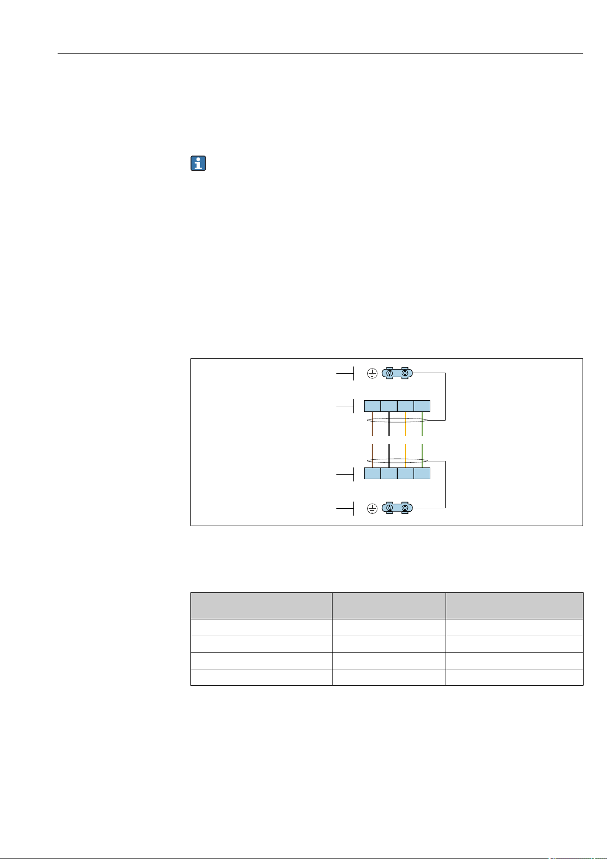
Proline Prowirl F 200 HART Electrical connection
Endress+Hauser 39
Connecting cable for remote version
Transmitter and sensor connection housing
In the case of the remote version, the sensor and transmitter are mounted separately from
on another and connected by a connecting cable. Connection is performed via the sensor
connection housing and the transmitter housing.
How the connecting cable is connected in the transmitter housing depends on the
measuring device approval and the version of the connecting cable used.
In the following versions, only terminals can be used for connection in the transmitter
housing:
• Certain approvals: Ex nA, Ex ec, Ex tb and Division 1
• Use of reinforced connecting cable
• Order code for «Sensor version; DSC sensor; measuring tube», option DA, DB
In the following versions, an M12 device connector is used for connection in the
transmitter housing:
• All other approvals
• Use of connecting cable (standard)
Terminals are always used to connect the connecting cable in the sensor connection
housing (tightening torques for screws for cable strain relief: 1.2 to 1.7 Nm).
Connecting cable (standard, reinforced)
+ –
+ –
2
1
1
2
1 2 3 4
1 2 3 4
GNYEWHBN
A0033476
12 Terminals for connection compartment in the transmitter wall holder and the sensor connection housing
1 Terminals for connecting cable
2 Grounding via the cable strain relief
Terminal number Assignment Cable color
Connecting cable
1 Supply voltage Brown
2 Grounding White
3 RS485 (+) Yellow
4 RS485 (–) Green
Connecting cable (option «mass pressure-/temperature-compensated»)
Order code for «Sensor version; DSC sensor; measuring tube», option DA, DB
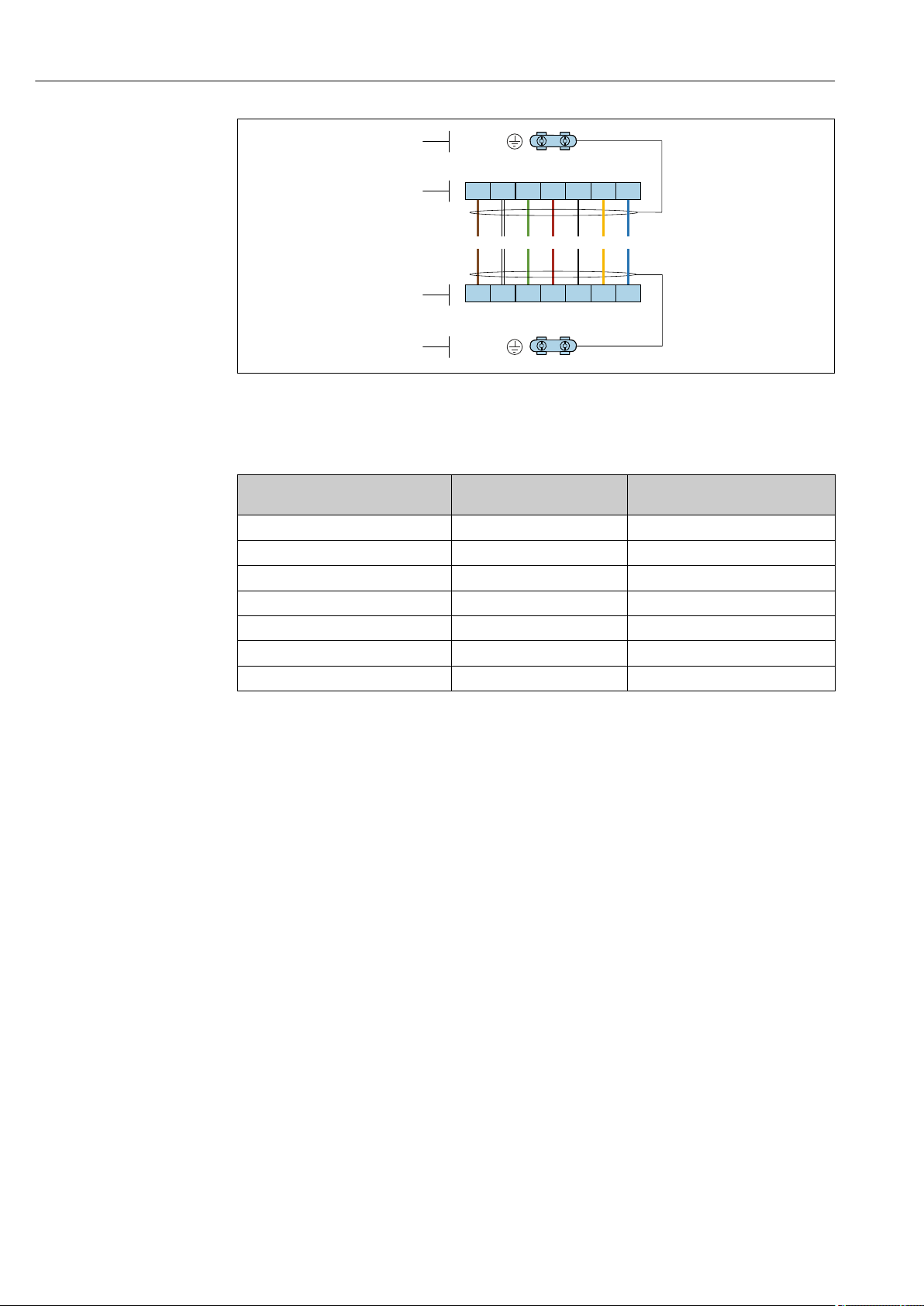
Electrical connection Proline Prowirl F 200 HART
40 Endress+Hauser
+–
+ –
2
1
1
2
1 2 3 4
1 2 3 4
5
5
6
6
7
7
RDGNWHBN BK YE BU
+–
+ –
RES
VCC
GND
RES
VCC
GND
A0034571
13 Terminals for connection compartment in the transmitter wall holder and the sensor connection housing
1 Terminals for connecting cable
2 Grounding via the cable strain relief
Terminal number Assignment Cable color
Connecting cable
1 RS485 (-) DPC Brown
2 RS485 (+) DPC White
3 Reset Green
4 Supply voltage red
5 Grounding Black
6 RS485 (+) Yellow
7 RS485 (–) Blue
7.1.5 Requirements for the supply unit
Supply voltage
Transmitter
An external power supply is required for each output.
The following supply voltage values apply for the outputs available:
Load
Load for current output: 0 to 500 Ω, depending on the external supply voltage of the power
supply unit
Calculation of the maximum load
Depending on the supply voltage of the power supply unit (U
S
), the maximum load (R
B
)
including line resistance must be observed to ensure adequate terminal voltage at the
device. In doing so, observe the minimum terminal voltage
• For U
S
= 17.9 to 18.9 V: R
B
≤ (U
S
— 17.9 V): 0.0036 A
• For U
S
= 18.9 to 24 V: R
B
≤ (U
S
— 13 V): 0.022 A
• For U
S
= ≥ 24 V: R
B
≤ 500 Ω
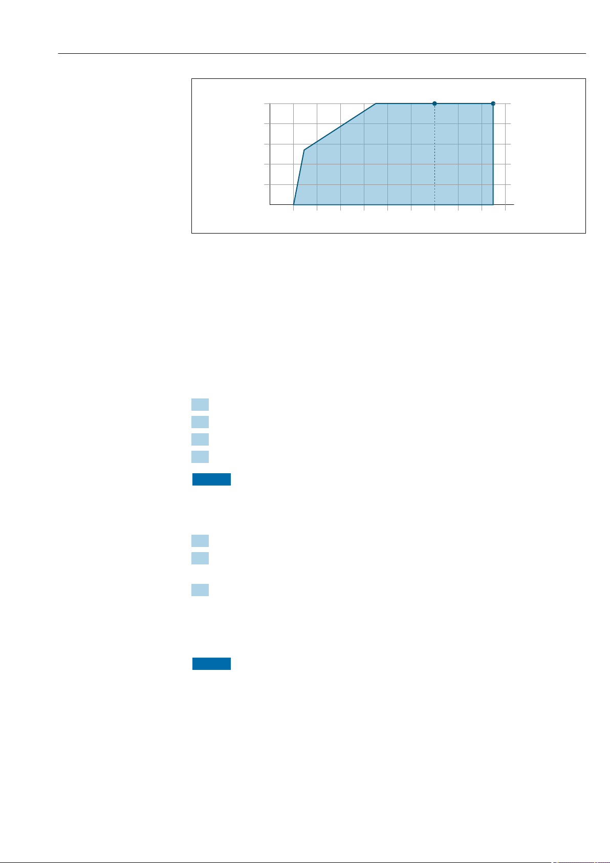
Proline Prowirl F 200 HART Electrical connection
Endress+Hauser 41
0
100
200
300
400
500
16 18 20
22 24
26 28 30 32
U [V]
S
R
B
[Ω]
34 36
A B
A0013563
A Operating range for order code for «Output», option A «4-20 mA HART»/option B «4-20 mA HART, pulse/
frequency/switch output» with Ex i and option C «4-20 mA HART + 4-20 mA analog»
B Operating range for order code for «Output», option A «4-20 mA HART»/option B «4-20 mA HART, pulse/
frequency/switch output» with non-Ex and Ex d
Sample calculation
Supply voltage of power supply unit: U
S
=19 V
Maximum load: R
B
≤ (19 V — 13 V): 0.022 A = 273 Ω
7.1.6 Preparing the measuring device
Carry out the steps in the following order:
1. Mount the sensor and transmitter.
2. Connection housing, sensor: Connect connecting cable.
3. Transmitter: Connect connecting cable.
4. Transmitter: Connect signal cable and cable for supply voltage.
NOTICE
Insufficient sealing of the housing!
Operational reliability of the measuring device could be compromised.
‣
Use suitable cable glands corresponding to the degree of protection.
1. Remove dummy plug if present.
2. If the measuring device is supplied without cable glands:
Provide suitable cable gland for corresponding connecting cable.
3. If the measuring device is supplied with cable glands:
Observe requirements for connecting cables → 36.
7.2 Connecting the measuring device
NOTICE
Limitation of electrical safety due to incorrect connection!
‣
Have electrical connection work carried out by appropriately trained specialists only.
‣
Observe applicable federal/national installation codes and regulations.
‣
Comply with local workplace safety regulations.
‣
Always connect the protective ground cable before connecting additional cables.
‣
For use in potentially explosive atmospheres, observe the information in the device-
specific Ex documentation.
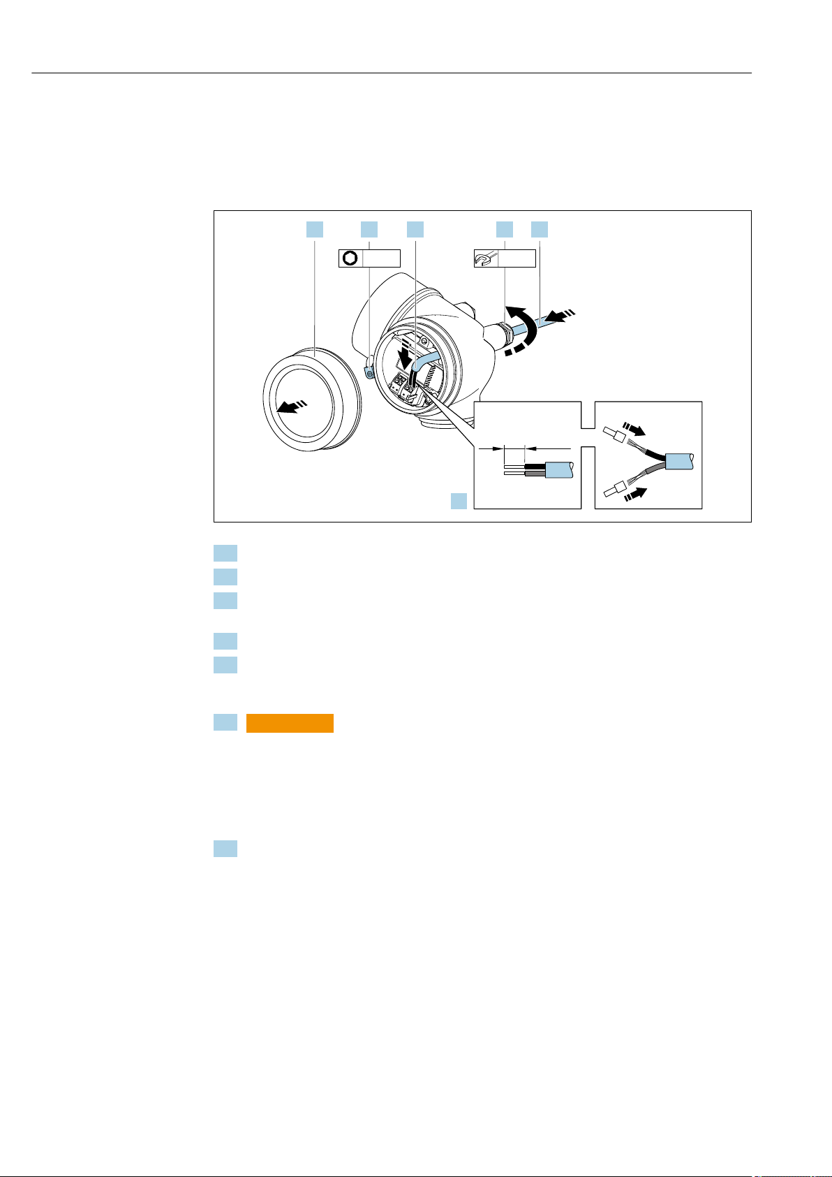
Electrical connection Proline Prowirl F 200 HART
42 Endress+Hauser
7.2.1 Connecting the compact version
Connecting the transmitter
Connection via terminals
10 (0.4)
mm (in)
20 mm3 mm
1.2. 3.
4.
5. 6.
A0032239
1. Loosen the securing clamp of the connection compartment cover.
2. Unscrew the connection compartment cover.
3. Push the cable through the cable entry . To ensure tight sealing, do not remove the
sealing ring from the cable entry.
4. Strip the cable and cable ends. In the case of stranded cables, also fit ferrules.
5. Connect cable in accordance with terminal assignment → 38. For HART
communication: when connecting the cable shielding to the ground clamp, observe
the grounding concept of the facility.
6.
L
WARNING
Housing degree of protection may be voided due to insufficient sealing of the
housing.
‣
Screw in the screw without using any lubricant. The threads on the cover are
coated with a dry lubricant.
Firmly tighten the cable glands.
7. Reverse the removal procedure to reassemble the transmitter.
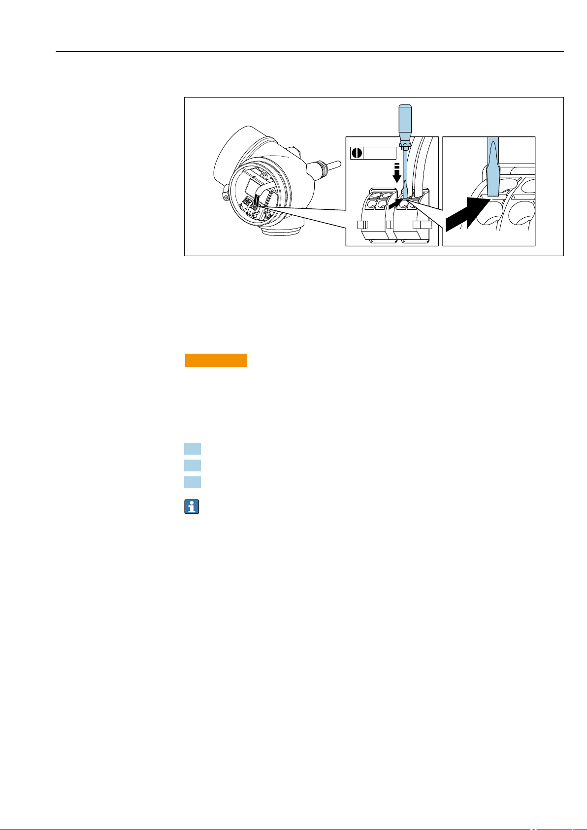
Proline Prowirl F 200 HART Electrical connection
Endress+Hauser 43
Removing a cable
A0032240
‣
To remove a cable from the terminal, use a flat-blade screwdriver to push the slot
between the two terminal holes while simultaneously pulling the cable end out of the
terminal.
7.2.2 Connecting the remote version
L
WARNING
Risk of damaging the electronic components!
‣
Connect the sensor and transmitter to the same potential equalization.
‣
Only connect the sensor to a transmitter with the same serial number.
The following procedure (in the action sequence given) is recommended for the remote
version:
1. Mount the sensor and transmitter.
2. Connect the connecting cable for the remote version.
3. Connect the transmitter.
How the connecting cable is connected in the transmitter housing depends on the
measuring device approval and the version of the connecting cable used.
In the following versions, only terminals can be used for connection in the transmitter
housing:
• Certain approvals: Ex nA, Ex ec, Ex tb and Division 1
• Use of reinforced connecting cable
• Order code for «Sensor version; DSC sensor; measuring tube», option DA, DB
In the following versions, an M12 device connector is used for connection in the
transmitter housing:
• All other approvals
• Use of connecting cable (standard)
Terminals are always used to connect the connecting cable in the sensor connection
housing (tightening torques for screws for cable strain relief: 1.2 to 1.7 Nm).
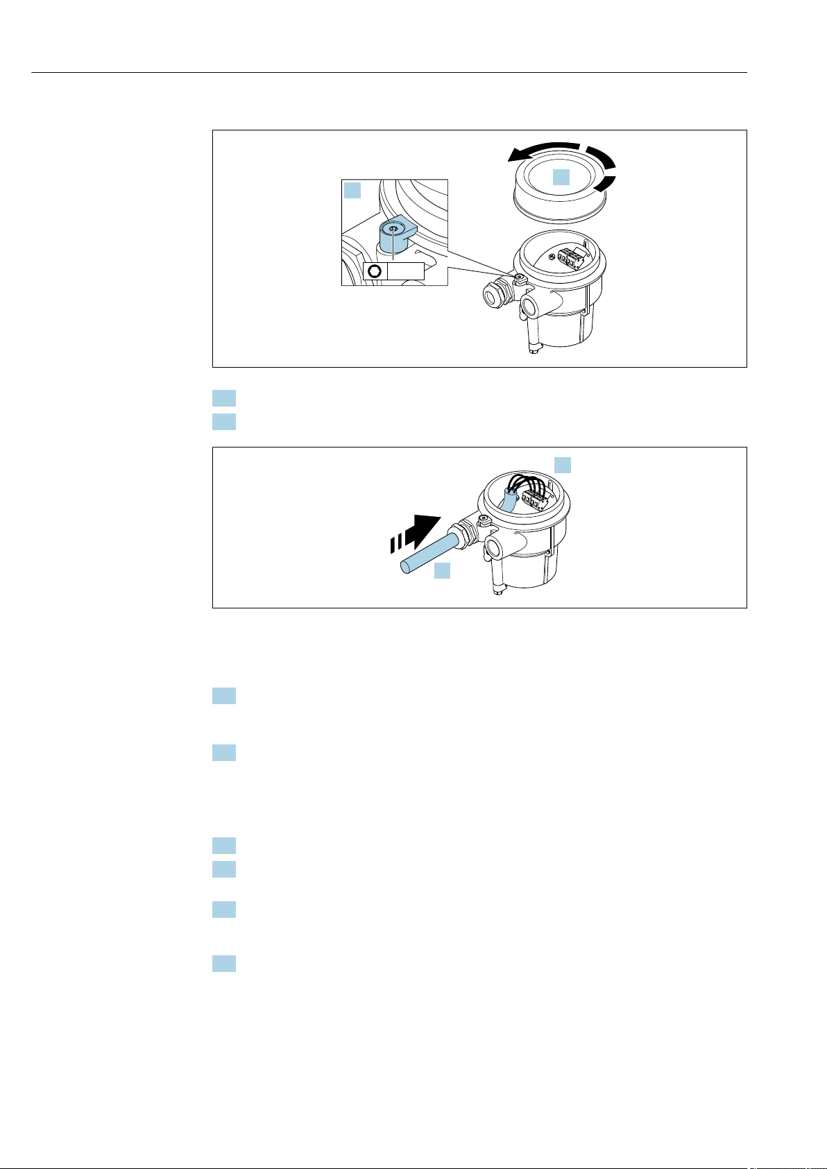
Electrical connection Proline Prowirl F 200 HART
44 Endress+Hauser
Connecting the sensor connection housing
A0034167
1. Loosen the securing clamp.
2. Unscrew the housing cover.
A0034171
14 Sample graphic
Connecting cable (standard, reinforced)
3. Guide the connecting cable through the cable entry and into the connection housing
(if using a connecting cable without an M12 device plug, use the shorter stripped end
of the connecting cable).
4. Wire the connecting cable:
Terminal 1 = brown cable
Terminal 2 = white cable
Terminal 3 = yellow cable
Terminal 4 = green cable
5. Connect the cable shield via the cable strain relief.
6. Tighten the screws for the cable strain relief using a torque in the range of
1.2 to 1.7 Nm.
7. Reverse the removal procedure to reassemble the connection housing.
Connecting cable (option «mass pressure-/temperature-compensated»)
3. Guide the connecting cable through the cable entry and into the connection housing
(if using a connecting cable without an M12 device plug, use the shorter stripped end
of the connecting cable).
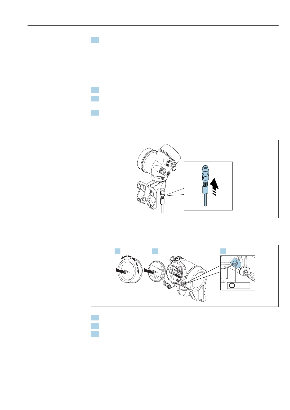
Proline Prowirl F 200 HART Electrical connection
Endress+Hauser 45
4. Wire the connecting cable:
Terminal 1 = brown cable
Terminal 2 = white cable
Terminal 3 = green cable
Terminal 4 = red cable
Terminal 5 = black cable
Terminal 6 = yellow cable
Terminal 7 = blue cable
5. Connect the cable shield via the cable strain relief.
6. Tighten the screws for the cable strain relief using a torque in the range of
1.2 to 1.7 Nm.
7. Reverse the removal procedure to reassemble the connection housing.
Connecting the transmitter
Connecting transmitter via plug
A0034172
‣
Connect the plug.
Connecting transmitter via terminals
A0034173
1. Loosen the securing clamp of the electronics compartment cover.
2. Unscrew the electronics compartment cover.
3. Pull out the display module with a gentle rotational movement. To make it easier to
access the lock switch, attach the display module to the edge of the electronics
compartment.
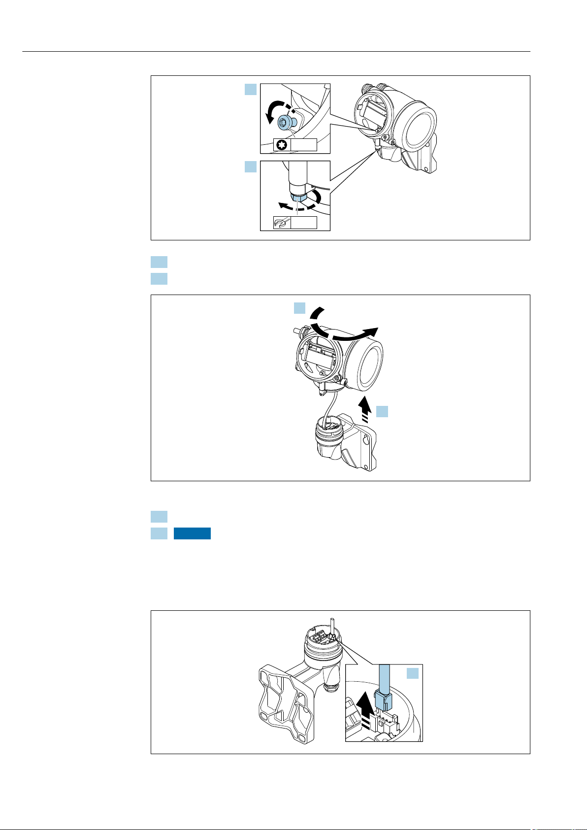
Electrical connection Proline Prowirl F 200 HART
46 Endress+Hauser
A0034174
4. Loosen the locking screw of the transmitter housing.
5. Loosen the securing clamp of the transmitter housing.
A0034175
15 Sample graphic
6. Turn the transmitter housing to the right until it reaches the marking.
7. NOTICE
The connection board of the wall housing is connected to the electronics board
of the transmitter via a signal cable!
‣
Pay attention to the signal cable when lifting the transmitter housing!
Lift the transmitter housing.
A0034176
16 Sample graphic
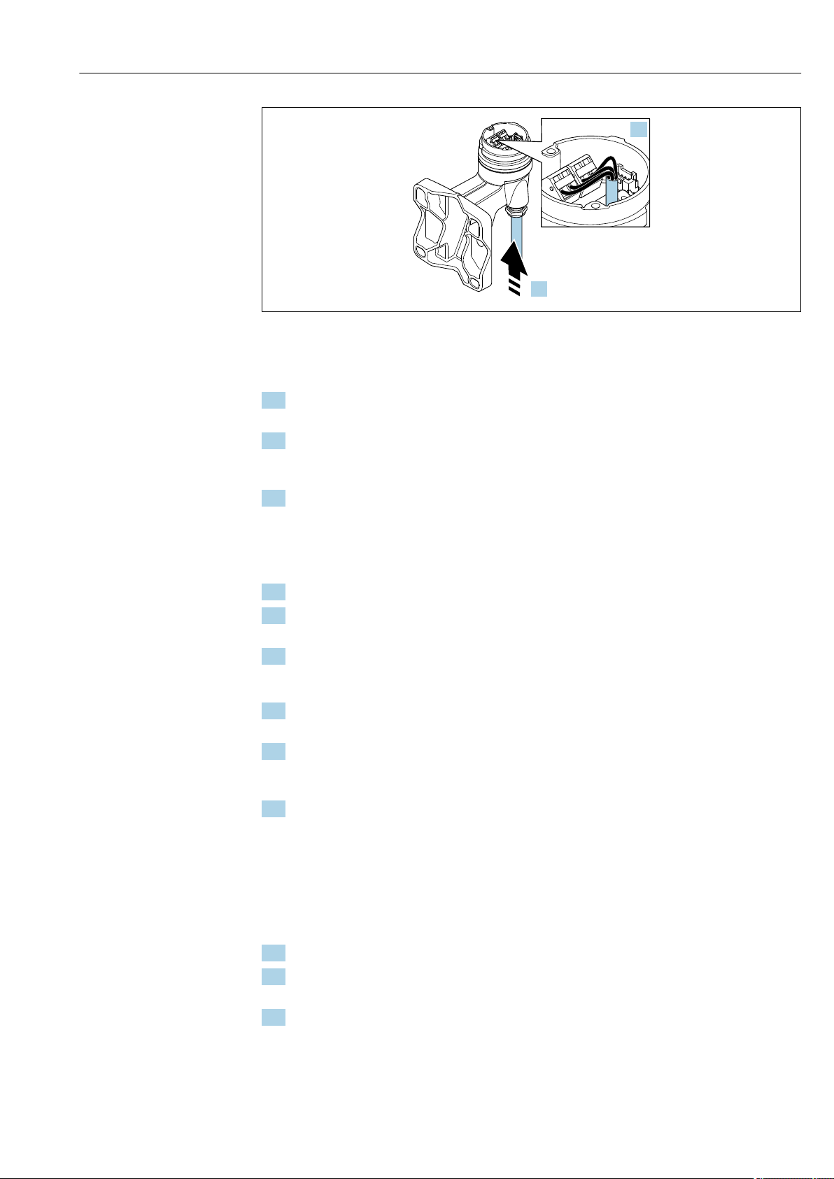
Proline Prowirl F 200 HART Electrical connection
Endress+Hauser 47
A0034177
17 Sample graphic
Connecting cable (standard, reinforced)
8. Disconnect the signal cable from the connection board of the wall housing . by
pressing in the locking clip on the connector. Remove the transmitter housing.
9. Guide the connecting cable through the cable entry and into the connection housing
(if using a connecting cable without an M12 device plug, use the shorter stripped end
of the connecting cable).
10. Wire the connecting cable:
Terminal 1 = brown cable
Terminal 2 = white cable
Terminal 3 = yellow cable
Terminal 4 = green cable
11. Connect the cable shield via the cable strain relief.
12. Tighten the screws for the cable strain relief using a torque in the range of
1.2 to 1.7 Nm.
13. Reverse the removal procedure to reassemble the transmitter housing.
Connecting cable (option «mass pressure-/temperature-compensated»)
8. Disconnect both signal cables from the connection board of the wall housing. by
pressing in the locking clip on the connector. Remove the transmitter housing.
9. Guide the connecting cable through the cable entry and into the connection housing
(if using a connecting cable without an M12 device plug, use the shorter stripped end
of the connecting cable).
10. Wire the connecting cable:
Terminal 1 = brown cable
Terminal 2 = white cable
Terminal 3 = green cable
Terminal 4 = red cable
Terminal 5 = black cable
Terminal 6 = yellow cable
Terminal 7 = blue cable
11. Connect the cable shield via the cable strain relief.
12. Tighten the screws for the cable strain relief using a torque in the range of
1.2 to 1.7 Nm.
13. Reverse the removal procedure to reassemble the transmitter housing.
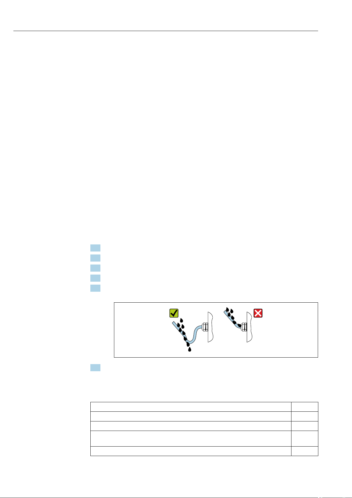
Electrical connection Proline Prowirl F 200 HART
48 Endress+Hauser
7.2.3 Connecting the connecting cable for the pressure measuring
cell
When delivered to the customer, the connecting cable is connected as follows:
• Compact version: to transmitter housing
• Remote version: to sensor connection housing
For connection to sensor and pressure measuring cell:
‣
Insert M12 plug of connecting cable into pressure measuring cell and screw into place.
7.2.4 Ensuring potential equalization
Requirements
Please consider the following to ensure correct measurement:
• Same electrical potential for the fluid and sensor
• Remote version: same electrical potential for the sensor and transmitter
• Company-internal grounding concepts
• Pipe material and grounding
7.3 Ensuring the degree of protection
The measuring device fulfills all the requirements for the IP66/67 degree of protection,
Type 4X enclosure.
To guarantee IP66/67 degree of protection, Type 4X enclosure, carry out the following
steps after the electrical connection:
1. Check that the housing seals are clean and fitted correctly.
2. Dry, clean or replace the seals if necessary.
3. Tighten all housing screws and screw covers.
4. Firmly tighten the cable glands.
5. To ensure that moisture does not enter the cable entry:
Route the cable so that it loops down before the cable entry («water trap»).
A0029278
6. Insert dummy plugs into unused cable entries.
7.4 Post-connection check
Are cables or the device undamaged (visual inspection)?
Do the cables used meet the requirements→ 36?
Do the mounted cables have adequate strain relief?
Are all cable glands installed, securely tightened and leak-tight? Cable run with «water trap»
→ 48?
Depending on the device version, are all the device plugs firmly tightened→ 42?

Proline Prowirl F 200 HART Electrical connection
Endress+Hauser 49
Only for remote version: is the sensor connected to the right transmitter?
Check the serial number on the nameplate of the sensor and transmitter.
Does the supply voltage match the specifications on the transmitter nameplate?
Is the terminal assignment correct ?
If supply voltage is present, do values appear on the display module?
Are all the housing covers installed and tightened?
Is the securing clamp tightened correctly?
Have the screws for the cable strain relief been tightened using the correct torque→ 43?
Has the M12 plug of the connecting cable been correctly connected to the pressure measuring
cell→ 48?
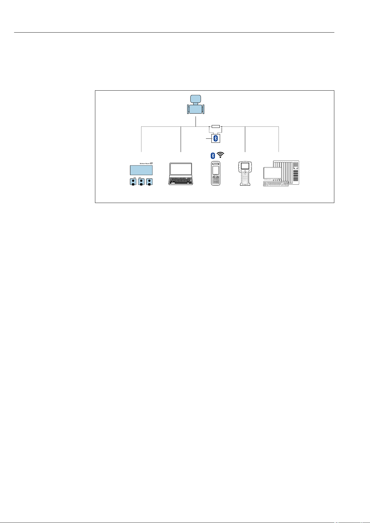
Operation options Proline Prowirl F 200 HART
50 Endress+Hauser
8 Operation options
8.1 Overview of operation options
A0032226
1 Local operation via display module
2 Computer with operating tool (e.g. FieldCare, DeviceCare, AMS Device Manager, SIMATIC PDM)
3 Field Xpert SFX350 or SFX370
4 Field Communicator 475
5 Control system (e.g. PLC)
6 VIATOR Bluetooth modem with connecting cable
 Loading…