-
Contents
-
Table of Contents
-
Troubleshooting
-
Bookmarks
Quick Links
Item # 32a
H
S
U
C
®
®
ARMONIC
CALPEL
LTRA
ISION
Generator 300 System User Manual
Manuel d’utilisation du Système de Générateur 300
Bedienungsanleitung für das Generator 300 System
Manuale dell’operatore del sistema generatore 300
Manual do utilizador do Sistema Gerador 300
Manual del usuario del sistema generador 300
Gebruikershandleiding generator 300-systeem
Brugermanual til generator 300 system
Generaattorijärjestelmän 300 käyttöopas
∂Á¯ÂÈÚ›‰ÈÔ XÚ‹Û˘ ÙÔ˘ ™˘ÛÙ‹Ì·ÙÔ˜ °ÂÓÓ‹ÙÚÈ· 300
Användarhandledning för generator 300-systemet
Instrukcja obs∏ugi systemu generatora 300
Generátor 300 rendszer Használati útmutató
UÏivatelská pfiíruãka systému Generator 300
PouÏívateºská príruãka pre systém Generator 300
Summary of Contents for Ethicon Endo-Surgery ULTRACISION HARMONIC SCALPEL Generator 300

Generator 300 System
User Manual
*
*Formerly known as
ULTRACISION®HARMONIC SCALPEL
®


GEN04
Table of Contents
Chapter 1 – General Information . . . . . . . . . . . . . . . . . . . . . . . . . . . . . . . . . . . . . . . . . . . . . . . . . . . . . . . . . 1
Indications . . . . . . . . . . . . . . . . . . . . . . . . . . . . . . . . . . . . . . . . . . . . . . . . . . . . . . . . . . . . . . . . . . . 1
Contraindications . . . . . . . . . . . . . . . . . . . . . . . . . . . . . . . . . . . . . . . . . . . . . . . . . . . . . . . . . . . . . 1
Chapter 2 – Principles of Operation . . . . . . . . . . . . . . . . . . . . . . . . . . . . . . . . . . . . . . . . . . . . . . . . . . . . . . 3
System Components . . . . . . . . . . . . . . . . . . . . . . . . . . . . . . . . . . . . . . . . . . . . . . . . . . . . . . . . . . . 3
Generator 300 . . . . . . . . . . . . . . . . . . . . . . . . . . . . . . . . . . . . . . . . . . . . . . . . . . . . . . . . . . . . 3
Hand Piece . . . . . . . . . . . . . . . . . . . . . . . . . . . . . . . . . . . . . . . . . . . . . . . . . . . . . . . . . . . . . . 3
Instrument . . . . . . . . . . . . . . . . . . . . . . . . . . . . . . . . . . . . . . . . . . . . . . . . . . . . . . . . . . . . . . . 3
Power Levels . . . . . . . . . . . . . . . . . . . . . . . . . . . . . . . . . . . . . . . . . . . . . . . . . . . . . . . . . . . . . . . . . 3
Controls, Indicators, and Connections . . . . . . . . . . . . . . . . . . . . . . . . . . . . . . . . . . . . . . . . . . . . . 4
Unpacking Instructions . . . . . . . . . . . . . . . . . . . . . . . . . . . . . . . . . . . . . . . . . . . . . . . . . . . . . . . . . 6
Chapter 3 – System Setup and Operation . . . . . . . . . . . . . . . . . . . . . . . . . . . . . . . . . . . . . . . . . . . . . . . . 7
System Startup . . . . . . . . . . . . . . . . . . . . . . . . . . . . . . . . . . . . . . . . . . . . . . . . . . . . . . . . . . . . . . . 7
System Operation . . . . . . . . . . . . . . . . . . . . . . . . . . . . . . . . . . . . . . . . . . . . . . . . . . . . . . . . . . . . . 9
System Shutdown . . . . . . . . . . . . . . . . . . . . . . . . . . . . . . . . . . . . . . . . . . . . . . . . . . . . . . . . . . . . 10
Chapter 4 – Troubleshooting . . . . . . . . . . . . . . . . . . . . . . . . . . . . . . . . . . . . . . . . . . . . . . . . . . . . . . . . . . . . 11
Audible Indicators and Alarms . . . . . . . . . . . . . . . . . . . . . . . . . . . . . . . . . . . . . . . . . . . . . . . . . . 11
Error Codes . . . . . . . . . . . . . . . . . . . . . . . . . . . . . . . . . . . . . . . . . . . . . . . . . . . . . . . . . . . . . . . . 11
Chapter 5 – Cleaning and Disinfection . . . . . . . . . . . . . . . . . . . . . . . . . . . . . . . . . . . . . . . . . . . . . . . . . . 17
Generator and Cart Cleaning . . . . . . . . . . . . . . . . . . . . . . . . . . . . . . . . . . . . . . . . . . . . . . . . . . 17
Foot Switch Cleaning . . . . . . . . . . . . . . . . . . . . . . . . . . . . . . . . . . . . . . . . . . . . . . . . . . . . . . . . . 17
Chapter 6 – Safety and Function Testing . . . . . . . . . . . . . . . . . . . . . . . . . . . . . . . . . . . . . . . . . . . . . . . . 19
Safety Test . . . . . . . . . . . . . . . . . . . . . . . . . . . . . . . . . . . . . . . . . . . . . . . . . . . . . . . . . . . . . . . . . . 19
Function Test . . . . . . . . . . . . . . . . . . . . . . . . . . . . . . . . . . . . . . . . . . . . . . . . . . . . . . . . . . . . . . . . 19
Calibration . . . . . . . . . . . . . . . . . . . . . . . . . . . . . . . . . . . . . . . . . . . . . . . . . . . . . . . . . . . . . . . . . 19
Chapter 7 – Warnings and Precautions . . . . . . . . . . . . . . . . . . . . . . . . . . . . . . . . . . . . . . . . . . . . . . . . . 21
System Warnings and Precautions . . . . . . . . . . . . . . . . . . . . . . . . . . . . . . . . . . . . . . . . . . . . . . . 21
Instrument Warnings and Precautions . . . . . . . . . . . . . . . . . . . . . . . . . . . . . . . . . . . . . . . . . . . . 22
Chapter 8 – System Specifications . . . . . . . . . . . . . . . . . . . . . . . . . . . . . . . . . . . . . . . . . . . . . . . . . . . . . . 23
Chapter 9 – Warranty . . . . . . . . . . . . . . . . . . . . . . . . . . . . . . . . . . . . . . . . . . . . . . . . . . . . . . . . . . . . . . . . . . 25
Chapter 10 – Symbols . . . . . . . . . . . . . . . . . . . . . . . . . . . . . . . . . . . . . . . . . . . . . . . . . . . . . . . . . . . . . . . . . . . 27


Please read all information carefully.
Failure to properly follow the instructions may lead to serious surgical consequences.
Important: The HARMONIC™ Generator 300 System User Manual is designed to provide instructions for use of the HARMONIC
Generator 300, Foot Switch, and Cart (see Chapter 8 – System Specifications for applicable product codes). This manual is not a
reference to surgical techniques.
Note: Refer to package inserts provided separately for information about the Hand Piece, Hand Switching Adaptor, Adaptors,
Test Tip and Instruments prior to using the system.
Indications
The HARMONIC System is indicated for soft tissue incisions when bleeding control and minimal thermal
injury are desired. The HARMONIC System instruments can be used as an adjunct to or substitute for
electrosurgery, lasers, and steel scalpels.
Contraindications
• The instruments are not indicated for incising bone.
• The instruments are not intended for contraceptive tubal occlusion.
Chapter 1 – General Information
1
GEN04


The HARMONIC System utilizes ultrasonic energy to enable hemostatic cutting and/or coagulation of soft
tissue. The system consists of an ultrasonic generator, a foot switch, an optional hand-switching adaptor, a
hand piece, and a variety of open and minimally invasive instruments.
Important: The HARMONIC Generator 300 System User Manual is designed to provide instructions for use of
the HARMONIC Generator 300, Foot Switch, and Cart (see Chapter 8 – System Specifications for applicable
product codes). This manual is not a reference to surgical techniques.
Note: Refer to package inserts provided separately for information about the Hand Piece, Hand Switching
Adaptor, Adaptors, Test Tip and Instruments prior to using the system.
System Components
Generator 300
The generator supplies the hand piece with electrical energy and facilitates selection of power levels, system
monitoring, and system diagnostics.
Power is delivered by activating the foot switch or hand switch.
Hand Piece
The hand piece contains an acoustic transducer that converts the electrical energy supplied by the generator
to mechanical motion. The transducer is connected to an amplifier which amplifies the motion produced by
the transducer and relays it to the instrument.
Instrument
The mechanical motion from the hand piece advances to the instrument, transmitting ultrasonic energy which
enables hemostatic cutting and/or coagulation of tissue.
Note: Throughout this manual “instrument(s)” refers to HARMONIC blades, ball coagulators, or coagulating
shears.
Power Levels
The generator delivers two power levels: minimum (MIN) and maximum (MAX). The minimum power
level may be adjusted by the user from Level 1 to 5. The maximum power level is always Level 5. With all
instruments except the ball coagulator, use a higher generator power level for greater tissue cutting speed and
a lower generator power level for greater coagulation. For the ball coagulator, higher generator power levels
will provide greater coagulation. The amount of energy delivered to the tissue and resultant tissue effects are
a function of many factors including the power level selected, instrument characteristics, grip force (when
applicable), tissue tension, tissue type, pathology, and surgical technique.
Note: Refer to the instruments’ package inserts for additional power level information, including
recommended starting power levels.
Chapter 2 – Principles of Operation
3GEN04

User Manual
4
GEN04
Controls, Indicators, and Connections
Fig. 2-1 Front Panel
1 READY When this indicator is green, the system is ready for activation.
2 STANDBY Push this button to toggle between Standby and Ready modes. In Standby mode,
this button, and the STANDBY icon, light up and all power is removed from the
hand piece. Both the foot switch and hand switch are disabled. Upon power-up, the
system defaults to Standby mode enabled.
3 INCREASE/ Push this button to increase or decrease the minimum (MIN) power
DECREASE POWER setting to the desired level (from 1 to 5). The level chosen will be shown on the
LEVEL graphic display. The power level may be adjusted when the generator is in Ready or
Standby mode.
4 POWER This switch controls the main electrical power to the generator.
5 VOLUME Turn this knob to adjust the volume of the activation tones. A tone will sound
indicating the volume level selected.
6MIN Indicates the user-settable minimum power level setting. When this power level is
activated (by foot switch or hand switch), the “MIN” indicator will flash. The
system defaults to “MIN” power level 3. Refer to the instruments’ package inserts
for the recommended minimum power level.
7 MAX Indicates the maximum power level setting. This setting is always “5”. When this
power level is activated (by foot switch or hand switch), the “MAX” indicator
will flash.
8 ALARM INDICATOR This red indicator appears only if a system alarm occurs in response to a component
or generator problem.
9 HAND PIECE This receptacle is used to connect the hand piece to the generator.
RECEPTACLE
10 HAND ACTIVATION When the indicator is green, hand activation on the hand switching adaptor is
enabled. To disable the Hand Activation mode, depress the button. Upon power-up,
the system defaults to Hand Activation mode disabled.
Note: If the foot switch is installed, the foot switch is always enabled.
11 TEST Depressing this button initiates the Test mode. This mode is used during
troubleshooting. The generator will emit a tone when the Test mode is active and
“TEST IN PROGRESS” will appear on the display.
12 GRAPHIC DISPLAY In Ready or Standby modes, this display indicates the minimum (user-settable
level 1 to 5) and maximum (level 5) power levels. If a system or component
problem exists, error codes will appear on this display.
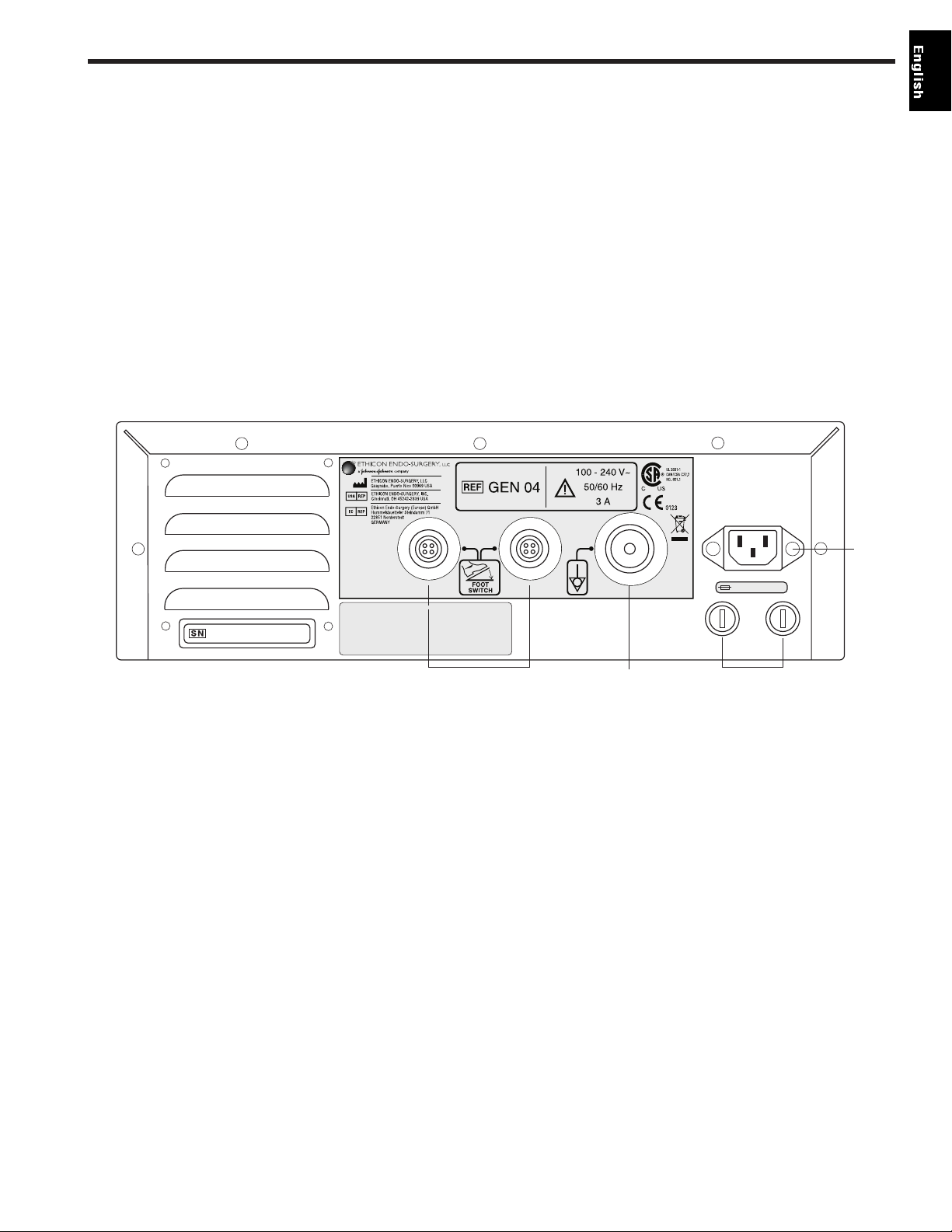
Fig. 2-2 Back Panel
13 FOOT SWITCH Identical receptacles allow connection of up to two foot switches for
RECEPTACLES user convenience. If only one foot switch is used, connect to either receptacle.
14 POTENTIAL This terminal provides a means for connection to a Potential Equalization
EQUALIZATION Conductor.
TERMINAL
15 FUSES See the H
ARMONIC Generator 300 Service Manual for additional information.
16 POWER CORD This receptacle is used to attach the power cord to the generator. For power cord
RECEPTACLE requirements, see Chapter 8 – System Specifications.
AUDIBLE SIGNALS The generator delivers audible tones to signal activation and alarm states. The user
may choose from three activation tone pitches. See Chapter 3 – System Setup and
Operation for tone selection information. Upon power-up, the system defaults to the
last tone chosen (the mid-pitch tone is factory-set).
Chapter 2 – Principles of Operation
5GEN04
T3.15H 250V
13 14 15
16
6,678,621
6,908,472
Covered by one or more of the following US Patents

GEN04
User Manual
6
Unpacking Instructions
The HARMONIC Generator 300 System includes several components that are purchased separately. Upon
receiving the ordered components, check for visible shipping damage. If damage is seen, contact your
Ethicon Endo-Surgery representative.
System components may include the following parts (for product codes, see Chapter 8 – System
Specifications):
Generator 300 – includes the generator, power cord, user manual, and service manual.
Note: The User Manual includes a troubleshooting guide (see back pocket of manual binder). Remove the
self-adhesive guide’s backing and adhere the guide to the top panel of the generator. Placement guides for the
Troubleshooting Guide are found on the generator’s top panel.
Foot Switch – includes the foot switch and detachable cable assembly.
Note: The foot switch is required if the system will be used with coagulating shears or instruments without
the hand switching adaptor. Since the generator has receptacles for two foot switches, two foot switches may
have been shipped.
Cart – the cart is optional. It is designed to hold one HARMONIC Generator. The cart requires assembly;
instructions are included with the cart.

System Startup
Warning: Products manufactured or distributed by companies other than Ethicon Endo-Surgery may not be
compatible with the HARMONIC System. Use of such products may lead to unanticipated results and possible
injury to the user or patient.
Caution: The HARMONIC system includes components that are shipped non-sterile (e.g. hand piece, hand
switching adaptor, adaptors, and blade wrench). Sterilize products as required before beginning system setup.
Refer to individual package inserts for cleaning and sterilization instructions.
1 Confirm that the generator power switch is off during setup.
2 Secure the generator on its cart or on another suitable fixture. To secure the generator on its
cart, place the generator’s rubber feet into the corresponding holes on the cart. Push down on
the generator’s top panel.
Caution: To prevent overheating during use, ensure that the air vents found on the
generator’s bottom and back panels are not blocked and that they allow adequate clearance
from obstructions to allow air to flow freely through the generator enclosure. Avoid placing
the generator on a soft surface.
Warning: The HARMONIC system must be operated within the required ambient operating
conditions. Refer to Chapter 8 – System Specifications for requirements.
Caution: Do not simultaneously touch the patient and generator.
3 Connect the line cord into the AC inlet located on the generator’s rear panel and into an
appropriately-grounded outlet. If the power cord is wrapped around the cart handle, it must
be completely removed from the cart handle prior to plugging it into the power outlet.
Warning: Verify that the outlet voltage correctly corresponds to the generator’s
requirements (see Chapter 8 – System Specifications). Connection to an improper power
supply may result in damage to the generator and risk of shock or fire hazard.
4a. Attach the foot switch cable to the foot switch:
Note: Although installation of the foot switch is optional when using the hand switching
adaptor, installing the foot switch is recommended in case its use is needed during the
procedure.
• Confirm that the connector and receptacle are dry and clean.
• Orient the slot on the foot switch cable’s larger connector at 12 o’clock.
• Seat the connector in the foot switch receptacle.
• Turn the connector collar clockwise until tight. Ensure the collar is finger-tight to
prevent inadvertent activation because of fluid ingress.
b. Connect the foot switch cable’s smaller connector to the foot switch receptacle on the rear
panel of the generator.
• Confirm that the connector and receptacle are dry and clean.
• Align the red dot on the foot switch 4-pin connector with the red dot on the 4-pin
receptacle on the generator back panel.
Note: The generator has two identical foot switch receptacles. If one foot switch is used,
either receptacle may be used.
Repeat steps 4a and 4b if a second foot switch will be used.
Chapter 3 – System Setup and Operation
7GEN04
 Loading…
- Manuals
- Brands
- Johnson & Johnson Manuals
- Medical Equipment
- Ethicon Endo-Surgery ULTRACISION HARMONIC SCALPEL
Manuals and User Guides for Johnson & Johnson Ethicon Endo-Surgery ULTRACISION HARMONIC SCALPEL. We have 1 Johnson & Johnson Ethicon Endo-Surgery ULTRACISION HARMONIC SCALPEL manual available for free PDF download: Service Manual
Service Manual for Johnson & Johnson Ethicon Endo-Surgery ULTRACISION HARMONIC SCALPEL Medical Equipment (31 pages)
Specifications:2310/2310516-ethicon_endosurgery_ultracision_harmonic_scalpel.pdf file (01 Jan 2023) |
Accompanying Data:
Johnson & Johnson Ethicon Endo-Surgery ULTRACISION HARMONIC SCALPEL Medical Equipment PDF Service Manual (Updated: Sunday 1st of January 2023 04:16:26 PM)
Rating: 4.3 (rated by 39 users)
Compatible devices: Biosense Webster EZ STEER THERMOCOOL NAV, DePuy Synthes TRAUMA Titanium Cannulated Tibial Nail, DePuy Mitek VAPR Series, DePuy Synthes VIPER System, DePuy Synthes Mitek Tibial Guide, DePuy Mitek GII Anchor, DePuy Synthes Electric Pen Drive, DePuy Synthes Kaneda.
Recommended Documentation:
Text Version of Service Manual
(Ocr-Read Summary of Contents of some pages of the Johnson & Johnson Ethicon Endo-Surgery ULTRACISION HARMONIC SCALPEL Document (Main Content), UPD: 01 January 2023)
-
10, 9 Two features of the system are user programmable. They are the displayed language and line rate. The system may be configured to display messages in languages other than the default setting of English. These languages are French, Spanish, Italian, and German. Also, the system can be configured to ru…
-
21, 6.3.4 Low Voltage Transformer Chapter 6 — Detailed Diagnostics continued The compressor is screwed to the base plate on rubber feet in the back portion of the Generator. It runs on line voltage supplied through the fusing and distribution module. When the front panel switch is turned on, the cooling fins on th…
-
14, The green power LED located on the keyboard PCB is driven from the +5 VDC supply on the generator PCB. The most likely mode of failure is no AC voltage leading to the Generator PCB. If no other generator activity is noticeable (i.e. air compressor noise, other LEDs, or displayed information), check the…
-
31, Johnson & Johnson Ethicon Endo-Surgery ULTRACISION HARMONIC SCALPEL REVISIONS LTR CAF NO. CHNG DATE — — 99-03869 CB 7-29-99 PRODUCT ARTWORK PACKAGE COMPONENT CODE NUMBER NUMBER GEN01 A83513P00 P40238P02 GEN22 GEN32 CONFIDENTIAL : NOT TO BE REPRODUCED OR USED IN ANY WAY WITHOUT WRITTEN ETHICON ENDO-SURGERY APPROVAL. CINCINNATI, OHIO BLACK
… -
6, Chapter 2 — Principles of Operation continued 5 POWER ENTRY MODULE/ FILTER FUSING & AC DISTRIBUTION HIGH VOLTAGE TRANSFORMER MICROPROCESSOR PCB GENERATOR PCB COMPRESSOR AIR (models HP050, HP051, HPTUV & H1TUV) KEYBOARD INTERLOCK FOOT- SWITCH HAND PIECE 55 KHz AC LCD LOW VOLTAGE TRANSFORMER Ge…
-
7, Johnson & Johnson Ethicon Endo-Surgery ULTRACISION HARMONIC SCALPEL 6 Chapter 3 — Basic Operation 3.1 Controls, Indicators, and Connections STANDBY SAVE FULL VARIABLE READY GENERATOR ETHICON ENDO-SURGERY 5432 1 ULTRACISION 1 2 3 4 5 6 7 10 11 12 9 8 13 Note: This illustration shows Generator Model GEN01. In Model GEN32, the position of the air and electrical connectors …
-
24, Johnson & Johnson Ethicon Endo-Surgery ULTRACISION HARMONIC SCALPEL 6.3.7 Keyboard/ Interlock PCB Chapter 6 — Detailed Diagnostics continued Replacement: 1. Remove the line cord and all cabling leading to the generator PCB. 2. Remove the two phillips head screws holding the processor in the service configuration and the six screws securing the generator PCB to the aluminum …
-
Johnson & Johnson Ethicon Endo-Surgery ULTRACISION HARMONIC SCALPEL User Manual
-
Johnson & Johnson Ethicon Endo-Surgery ULTRACISION HARMONIC SCALPEL User Guide
-
Johnson & Johnson Ethicon Endo-Surgery ULTRACISION HARMONIC SCALPEL PDF Manual
-
Johnson & Johnson Ethicon Endo-Surgery ULTRACISION HARMONIC SCALPEL Owner’s Manuals
Recommended: MA1201, L110, VT-1407


-
Allergan REVOLVE System
REVOLVE™ System ComponentsREVOLVE™ System Unit PartsUser Provided ComponentsSterile barrier inside box contains: REVOLVE™ SystemVacuum Connecon TubingIrrigaon TubingElbow is removable on this end5. Lactated Ringer’s SoluonHandle1. Liposucon Tube2. Connect to medical grade …
REVOLVE System 2
-
AKO-med Socks-jet
User manual Socks-jet I. Preparation Step 1 Place the Socks-jet on a flat, dry surface. The hand grip points towards you and the open tube side to the front. Wear rubber gloves to protect your stockings. Step 2 Pull the stocking over the tube body and make sure that the stocking tip is facing forward. …
Socks-jet 4
-
Woodpecker DTE Implant-X
The pictures are only for reference. The nal interpretation rights belong to Guilin Woodpecker Medical Instrument Co., Ltd. Woodpecker reserves the right to change the design of the equipment, the technique, ttings, instruction manual and the content of the original packing list at any time without further …
DTE Implant-X 34
-
Sizewise Platinum Series
User Manual Rev. 2.0 #8046 SIZEWISE 10.05.2015 User Manual Platinum 6000™ Alternating Pressure Low Air Loss Mattress Replacement System …
Platinum Series 28
Additional Information:
Popular Right Now:
Operating Impressions, Questions and Answers:
 Loading…
- Manuals
- Brands
- Johnson & Johnson Manuals
- Medical Equipment
- Ethicon Endo-Surgery ULTRACISION HARMONIC SCALPEL
Manuals and User Guides for Johnson & Johnson Ethicon Endo-Surgery ULTRACISION HARMONIC SCALPEL. We have 1 Johnson & Johnson Ethicon Endo-Surgery ULTRACISION HARMONIC SCALPEL manual available for free PDF download: Service Manual
Service Manual for Johnson & Johnson Ethicon Endo-Surgery ULTRACISION HARMONIC SCALPEL Medical Equipment (31 pages)
Specifications:2310/2310516-ethicon_endosurgery_ultracision_harmonic_scalpel.pdf file (01 Jan 2023) |
Accompanying Data:
Johnson & Johnson Ethicon Endo-Surgery ULTRACISION HARMONIC SCALPEL Medical Equipment PDF Service Manual (Updated: Sunday 1st of January 2023 04:16:26 PM)
Rating: 4.3 (rated by 39 users)
Compatible devices: Biosense Webster EZ STEER THERMOCOOL NAV, DePuy Synthes TRAUMA Titanium Cannulated Tibial Nail, DePuy Mitek VAPR Series, DePuy Synthes VIPER System, DePuy Synthes Mitek Tibial Guide, DePuy Mitek GII Anchor, DePuy Synthes Electric Pen Drive, DePuy Synthes Kaneda.
Recommended Documentation:
Text Version of Service Manual
(Ocr-Read Summary of Contents of some pages of the Johnson & Johnson Ethicon Endo-Surgery ULTRACISION HARMONIC SCALPEL Document (Main Content), UPD: 01 January 2023)
-
10, 9 Two features of the system are user programmable. They are the displayed language and line rate. The system may be configured to display messages in languages other than the default setting of English. These languages are French, Spanish, Italian, and German. Also, the system can be configured to ru…
-
21, 6.3.4 Low Voltage Transformer Chapter 6 — Detailed Diagnostics continued The compressor is screwed to the base plate on rubber feet in the back portion of the Generator. It runs on line voltage supplied through the fusing and distribution module. When the front panel switch is turned on, the cooling fins on th…
-
14, The green power LED located on the keyboard PCB is driven from the +5 VDC supply on the generator PCB. The most likely mode of failure is no AC voltage leading to the Generator PCB. If no other generator activity is noticeable (i.e. air compressor noise, other LEDs, or displayed information), check the…
-
31, Johnson & Johnson Ethicon Endo-Surgery ULTRACISION HARMONIC SCALPEL REVISIONS LTR CAF NO. CHNG DATE — — 99-03869 CB 7-29-99 PRODUCT ARTWORK PACKAGE COMPONENT CODE NUMBER NUMBER GEN01 A83513P00 P40238P02 GEN22 GEN32 CONFIDENTIAL : NOT TO BE REPRODUCED OR USED IN ANY WAY WITHOUT WRITTEN ETHICON ENDO-SURGERY APPROVAL. CINCINNATI, OHIO BLACK
… -
6, Chapter 2 — Principles of Operation continued 5 POWER ENTRY MODULE/ FILTER FUSING & AC DISTRIBUTION HIGH VOLTAGE TRANSFORMER MICROPROCESSOR PCB GENERATOR PCB COMPRESSOR AIR (models HP050, HP051, HPTUV & H1TUV) KEYBOARD INTERLOCK FOOT- SWITCH HAND PIECE 55 KHz AC LCD LOW VOLTAGE TRANSFORMER Ge…
-
7, Johnson & Johnson Ethicon Endo-Surgery ULTRACISION HARMONIC SCALPEL 6 Chapter 3 — Basic Operation 3.1 Controls, Indicators, and Connections STANDBY SAVE FULL VARIABLE READY GENERATOR ETHICON ENDO-SURGERY 5432 1 ULTRACISION 1 2 3 4 5 6 7 10 11 12 9 8 13 Note: This illustration shows Generator Model GEN01. In Model GEN32, the position of the air and electrical connectors …
-
24, Johnson & Johnson Ethicon Endo-Surgery ULTRACISION HARMONIC SCALPEL 6.3.7 Keyboard/ Interlock PCB Chapter 6 — Detailed Diagnostics continued Replacement: 1. Remove the line cord and all cabling leading to the generator PCB. 2. Remove the two phillips head screws holding the processor in the service configuration and the six screws securing the generator PCB to the aluminum …
-
Johnson & Johnson Ethicon Endo-Surgery ULTRACISION HARMONIC SCALPEL User Manual
-
Johnson & Johnson Ethicon Endo-Surgery ULTRACISION HARMONIC SCALPEL User Guide
-
Johnson & Johnson Ethicon Endo-Surgery ULTRACISION HARMONIC SCALPEL PDF Manual
-
Johnson & Johnson Ethicon Endo-Surgery ULTRACISION HARMONIC SCALPEL Owner’s Manuals
Recommended: MA1201, L110, VT-1407
-
Allergan REVOLVE System
REVOLVE™ System ComponentsREVOLVE™ System Unit PartsUser Provided ComponentsSterile barrier inside box contains: REVOLVE™ SystemVacuum Connecon TubingIrrigaon TubingElbow is removable on this end5. Lactated Ringer’s SoluonHandle1. Liposucon Tube2. Connect to medical grade …
REVOLVE System 2
-
AKO-med Socks-jet
User manual Socks-jet I. Preparation Step 1 Place the Socks-jet on a flat, dry surface. The hand grip points towards you and the open tube side to the front. Wear rubber gloves to protect your stockings. Step 2 Pull the stocking over the tube body and make sure that the stocking tip is facing forward. …
Socks-jet 4
-
Woodpecker DTE Implant-X
The pictures are only for reference. The nal interpretation rights belong to Guilin Woodpecker Medical Instrument Co., Ltd. Woodpecker reserves the right to change the design of the equipment, the technique, ttings, instruction manual and the content of the original packing list at any time without further …
DTE Implant-X 34
-
Sizewise Platinum Series
User Manual Rev. 2.0 #8046 SIZEWISE 10.05.2015 User Manual Platinum 6000™ Alternating Pressure Low Air Loss Mattress Replacement System …
Platinum Series 28
Additional Information:
Popular Right Now:
Operating Impressions, Questions and Answers:
1 934 336 ₽
Нашли этот товар дешевле?
Этот товар продается поштучно.
Доставка по России:
Отправка осуществляется ТК СДЭК. Доставку оплачивает покупатель при получении товара. При заказе на сумму более 20 000 ₽ доставка осуществляется бесплатно.
Сертификаты:
-
Описание
-
Характеристики
Описание
Принцип работы:
Электрическая энергия, исходящая из генератора, управляемого микропроцессорами, преобразуется в механические колебания системой пьезокерамических кристаллов, расположенных в лапаросонической рукоятке. Лезвие инструмента вибрирует в продольном направлении с частотой 55,5 кГц. Амплитуда продольных колебаний варьируется в пределах 50–100 мкм на 5 уровнях при помощи установки параметров на передней панели генератора. Инструменты и технология Гармоник применяется для рассечения мягких тканей при необходимости надежного гемостаза с минимальным латеральным термическим поражением. Диссекция происходит вследствие механического растяжения тканей выше пределов эластичности. Коагуляция тканей происходит вследствие ультразвуковых механических колебаний молекул белков с их последующей денатурацией. Инструменты и технология Гармоник могут использоваться как замена моно- и биполярных инструментов, лазера или традиционного скальпеля, а также в сочетании с ними.
Аппарат функционирует в двух режимах – биполярном и ультразвуковом. В ультразвуковом режиме аппарат функционирует без воздействия электротока на пациента, при помощи механических высокочастотных колебаний лезвия насадки с одновременной диссекцией тканей, коагуляцией сосудов до 5 мм в диаметре и кавитационным препарированием тканей. Частота колебаний лезвия в ультразвуковом режиме – 55,5 кГц. В ультразвуковом режиме имеется 5 уровней изменения амплитуды движения рабочей насадки, с функцией ее регулировки. В режиме биполярной диссекции-коагуляции генератор работает с воздействием электротока на ткани, позволяя пересекать и коагулировать ткани, а также лигировать сосуды диаметром до 7 мм включительно. Имеется система оценки импеданса тканей для автоматического завершения цикла коагуляции и минимизации термического повреждения тканей. Поддержка биполярной коагуляции с автоматическим и полностью ручным завершением цикла коагуляции. Генератор обладает функцией автоматического распознавания подключенных насадок для минимизации потерь времени на их настройку. Совместимость со следующими типами рабочих насадок (диаметром 5 и 10 мм): ультразвуковые лезвия и ножницы, а также насадки биполярной коагуляции как для открытых, так и эндоскопических операций. Возможность ручной и педальной активации насадок. Все насадки могут применяться у пациентов с кардиостимуляторами. Возможность работы насадок вблизи жизненно важных структур с минимальным латеральным повреждением тканей, с возможностью разреза тканей обратной стороной рабочих насадок. Совместимость с биполярными насадками с ограничением температурного повреждения тканей не более 100 градусов С и возможностью коагуляции сосудов диаметром до 7 мм с возможностью разреза тканей. Наличие системы самотестирования генератора, ультразвуковой рукояти и насадок. Возможность принудительного тестирования генератора. Возможность тестирования при помощи тестового ключа в каждом из режимов работы (ультразвуковой, биполярный). Возможность обновления внутреннего программного обеспечения генератора. Наличие USB-разъема для проведения обновления и обслуживания генератора. Индикация количеств активации ультразвуковых рукоятей. Наличие на передней панели цветного дисплея с функцией распознавания прикосновения. Наличие на передней панели генератора визуальной индикации с отображением уровней мощности и возможностью регулировки уровней мощности. Возможность настройки генератора через пользовательское меню. Визуальная индикация ошибок и способов их устранения. Звуковая индикация режимов работы и ошибок с возможностью регулировки уровня громкости. Пользовательский интерфейс русифицирован. Защита разъемов от некорректного подключения штекеров. Наличие системы предотвращения случайного выпадения штекеров рукоятей и насадок из гнезда генератора. Возможность подключения адаптеров для работы ультразвуковыми и биполярными насадками подходящими к генераторам GEN04 и RF60. Возможность комплектования генератора специальной мобильной тележкой-подставкой с местом для хранения принадлежностей. Совместимость с ножным двухпедальным приводом с маркировкой соответствующего педали режима, имеющим защиту от деформации силового провода. Противоскользящее покрытие нижней поверхности ножного педального привода.
Потребляемая мощность генератора 500 ВА, работа в сети переменного тока с напряжением 100-240 В, частота 50/60 Гц.
Выходная мощность 135 Вт в биполярном режиме, 35 Вт в ультразвуковом режиме.
Габариты генератора – 13,6х35,5х35,0 см.
Масса генератора – 5,9 кг.
Соответствие стандарту IEC 60601-2-2:2009 (Группа 1), отсутствие РЧ-наводок на окружающее электронное оборудование.
Защита корпуса G11 от проникновения – IP21. Генератор поставляется в коплекте с сетевым кабелем IEC 60320 C13 с прямым кабельным вводом без углов.
Гарантия на генератор 12 месяцев.
Наличие авторизованного сервисного центра на территории РФ.
Ключевые свойства:
• Две передовые технологии — Гармоник и Энсил — в одном генераторе. Обеспечена совместимость со всеми существующими инструментами
• Простота установки и использования аппарата. Большой сенсорный дисплей с русским интерфейсом для легкой навигации по меню и выбору настроек
• Интуитивность и информативность. Один универсальный разъем с автоматическим распознаванием подключенного инструмента и технологии
• Возможность обновления ПО через USB-порт. Обеспечит совместимость генератора со всеми инновационными инструментами Ethicon Energy
• Безупречный компактный дизайн позволяет G11 разместиться в любой, даже самой небольшой и заставленной оборудованием операционной
• Баланс диссекции и коагуляции представлен пятью уровнями регулировки амплитуды колебаний лезвия. Уровни 4 и 5 предназначены для быстрого разделения маловаскуляризированных тканей с их одновременной коагуляцией. Уровень 3 является оптимальным с точки зрения баланса диссекции/коагуляции, уровни 1 и 2 предпочтительны для более выраженной коагуляции (хорошо васкуляризированные ткани)
Характеристики
| Артикул: | GEN11 |
| Производитель: | Ethicon (Johnson & Johnson) |
| Кол-во в запечатанной фабричной упаковке: | 1 шт |
| Наименование от производителя (ENG): | Generator Gen11 |
| Наименование от производителя (РУС): | Генератор электрохирургический, ультразвуковой G11 |