")
Новости
11июл
С 2023 года ООО «Айпиком системс» стала дистрибьютором компании PAL Electronics Systems Ltd, производящей самые лучшие и функциональные GSM-модули в мире.
Подробнее
26янв
В продажу поступил GSM модуль «ДОМОВОЙ».
Подробнее
24янв
С 24 января произошло анонсируемое повышение цен на продукцию FAAC.
Подробнее
10янв
Информируем Вас о планируемом повышении цен на продукции FAAC c начала 2022 года.
Подробнее
- Home
- Инструкции
- Автоматика для ворот
- FAAC
- 844
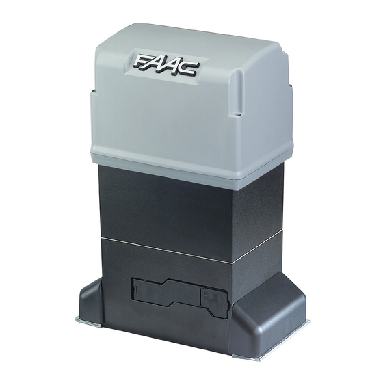
![]() Автоматика для откатных ворот FAAC 844 инструкция по эксплуатации и монтажу на русском языке в формате pdf, размер файла 1.9 Mb. Используйте кнопки «Скачать инструкцию» или «Открыть в новом окне» (документ откроется в новом окне или вкладке браузера). Функция просмотра доступна при наличии плагина Adobe Acrobat в вашем браузере.
Автоматика для откатных ворот FAAC 844 инструкция по эксплуатации и монтажу на русском языке в формате pdf, размер файла 1.9 Mb. Используйте кнопки «Скачать инструкцию» или «Открыть в новом окне» (документ откроется в новом окне или вкладке браузера). Функция просмотра доступна при наличии плагина Adobe Acrobat в вашем браузере.
FAAC 844 инструкция
Язык: Русский
Размер : 1.9 Mb
Формат файла: pdf
Добавлен: 04.06.2013
Руководство по установке и использованию
Предварительный просмотр

Информация, описание, технические характеристики изделия
Описание и информация о технических характеристиках по данному изделию пока что отсутствует. Содержание во всех разделах сайта периодически обновляется. Попробуйте зайти на страницу позже.
Отзывы по оборудованию и комментарии к материалу
Здесь можно оставить свои отзывы по оборудованию «FAAC 844 — Откатные ворота», а также написать комментарии к материалу.
- Manuals
- Brands
- FAAC Manuals
- Gate Opener
- 844ER
- Manual
-
Contents
-
Table of Contents
-
Bookmarks
Quick Links
844ER & 780D
844ER & 780D
Related Manuals for FAAC 844ER
Summary of Contents for FAAC 844ER
-
Page 1
844ER & 780D 844ER & 780D… -
Page 2: Ec Declaration Of Conformity For Machines
17) Use of at least one indicator-light (e.g. FAACLIGHT ) is recommended 6) FAAC declines all liability caused by improper use or use other than that for every system, as well as a warning sign adequately secured to the for which the automated system was intended.
-
Page 3: Description And Technical Specifications
844 ER Z16 CR — 844 R — 844 R CAT — 844 R RF Ta = opening time The FAAC mod. 844 automated system for sliding gates is an Tc = closing time electro-mechanical operator transmitting motion to the sliding leaf Tp = pause time via a rack or chain pinion appropriately coupled to the gate.
-
Page 4: Masonry For Foundation Plate
To make the connections efficiently, allow the cables to project 2. DIMENSIONS by about 40 cm from the hole (Figs.5-6 ref. ) of the foundation plate. Fig. 4 Fig. 2 3. ELECTRIC EQUIPMENT (standard system) Fig. 5 ³ Operator 844 with 780D equipment Photocells Key-operated push-button…
-
Page 5: Installing The Rack
5) Secure the gearmotor to the foundation plate, tightening the nuts as in Fig.12. 6) Prepare the operator for manual operating mode as described in chapter 8. Fig. 12 Fig. 8 4.4. INSTALLING THE RACK 4.4.1. STEEL RACK TO WELD (Fig.13) 1) Place the three threaded pawls on the rack element, positioning them at the top of the slot.
-
Page 6: Installation Of Chain Pinions
4.5.2. MOD. 844 ER RF (Figs. 20 — 21) 1) Insert the spring pin on the shaft, using a hammer. 2) Fit the idle transmissions bracket on the gearmotor flange, using the four screws (M5 x 12) and the appropriate washers , in the kit as shown in Fig.
-
Page 7: Layout And Components
5.3. LAYOUT AND COMPONENTS 5. CONTROL BOARD 780D SIGNALLING AND PROGRAMMING DISPLAY 5.1. WARNINGS Led INPUTS STATUS CONTROL LED Important: Before attempting any work on the control board LOW VOLTAGE TERMINAL BOARD (connections, maintenance), always turn off power. Install, upstream of the system, a differential thermal breaker with CONNECTOR FOR DECODER/MINIDEC/RP RECEIVER adequate tripping threshold.
-
Page 8: Electric Connections
Opening safety devices: they are tripped when an obstacle is 5.4. ELECTRIC CONNECTIONS detected only during gate opening movement. They cause immediate closure and resumption of opening motion on release (see programming in par. 5.5.2.) 230Vac 50-60Hz Closing safety devices: they are tripped when an obstacle is detected only during gate closing movement.
-
Page 9
Connection of two pairs of closing photocells and two Connection of a pair of opening photocells edge safety devices Fig. 29 Connection of a pair of closing photocells Fig. 32 Connection of a pair of closing photocells, a pair of opening photocells and a pair of opening/closing photocells Fig. -
Page 10
To install several partial opening pulse generators, Connection of a pair of closing photocells and a pair of connect the N.O. contacts in parallel (fig.35). opening/closing photocells FSW OP — Opening safety devices contact (terminal 3): The purpose of the opening safety devices is to protect the leaf movement area during opening. -
Page 11: Basic Programming
TX -FSW — Negative for power supply to photocell transmitters 5.5. PROGRAMMING (terminal 11) To program operation of the automated system, access the If you use this terminal for connecting the negative for «PROGRAMMING» mode with keys F,+ and -, and using the supplying power to the photocell transmitters, you may, if display on the equipment.
-
Page 12: Advanced Programming
Display Function Default Display Function Default FORCE: FAIL SAFE: Adjusts Motor thrust. If this function is activated, it enables a function test of the photocells before any gate = minimum force movement. If the test fails (photocells not = maximum force serviceable signalled by value on the display), the gate does not start moving.
-
Page 13
Display Function Default Display Function Default OPENING PHOTOCELLS LOGIC: PARTIAL OPENING: Select the tripping mode of the opening You can adjust the width of partial leaf opening. photocells. Time can be adjusted from They operate for the opening movement only: 1-second steps. -
Page 14: Definition Of Opening Direction And Operation Of Limit-Switch Leds
Attention: due to the powerful magnetic fields the supplied 6. START-UP magnets produce, the magnets can damage magnetic band 6.1. ELECTRIC CONNECTIONS components (credit cards, magnetic tapes, floppy disks, etc) and electronic and mechanical equipment (e.g. watches, Make all electrical connections to the board as in chapter 5, LCD screens).
-
Page 15: Final Operations
Notes on plate positioning • To ensure correct operation, allow at least 2 cm from the mechanical stop limit in the gate stop position. Carry out this check after determining the values of the pre- and post-limit switch decelerations (see par. 5.5.2.) and after running at least one complete cycle of the automated system.
-
Page 16: Manual Operation
10.INSTALLING THE CN 60E CONTROL UNIT (OPTIONAL) The operator is designed to house (with the aid of a DIN bar) the CN 60E control unit of the safety conductive edge. Cut the DIN bar to measure and secure it to the operator with two screws in the appropriate holes and attach the CN 60E control unit to it (Fig.
-
Page 17: Maintenance
Oil level (visually checked) must be in line with the copper windings of the electric motor. To top up, pour in oil up to the required level. Use FAAC XD 220 oil only. Fig. 54 15.REPAIRS For any repairs, contact the FAAC authorised Repair Centres.
-
Page 20: General Safety Regulations
— Do not attempt any kind of repair of direct action whatsoever and contact FAAC qualified personnel only. — Call in qualified personnel at least every 6 months to check the efficiency of the automated system, safety devices and earth connection.
-
Page 22
Le descrizioni e le illustrazioni del presente manuale non sono impegnative. La FAAC si riserva il diritto, lasciando inalterate le caratteristiche essenziali dell’apparecchiatura, di apportare in qualunque momento e senza impegnarsi ad aggiornare la presente pubblicazione, le modifiche che essa ritiene convenienti per miglioramenti tecnici o per qualsiasi altra esigenza di carattere costruttivo o commerciale.
This manual is also suitable for:
780d844