- Home
- Инструкции
- Автоматика для ворот
- FAAC
- D1000
![]() Автоматика для гаражных ворот FAAC D1000 инструкция по эксплуатации и монтажу на русском языке в формате pdf, размер файла 1.7 Mb. Используйте кнопки «Скачать инструкцию» или «Открыть в новом окне» (документ откроется в новом окне или вкладке браузера). Функция просмотра доступна при наличии плагина Adobe Acrobat в вашем браузере.
Автоматика для гаражных ворот FAAC D1000 инструкция по эксплуатации и монтажу на русском языке в формате pdf, размер файла 1.7 Mb. Используйте кнопки «Скачать инструкцию» или «Открыть в новом окне» (документ откроется в новом окне или вкладке браузера). Функция просмотра доступна при наличии плагина Adobe Acrobat в вашем браузере.
FAAC D1000 инструкция
Язык: Русский
Размер : 1.7 Mb
Формат файла: pdf
Добавлен: 04.06.2013
Руководство по установке и использованию
Предварительный просмотр

Информация, описание, технические характеристики изделия
Описание и информация о технических характеристиках по данному изделию пока что отсутствует. Содержание во всех разделах сайта периодически обновляется. Попробуйте зайти на страницу позже.
Отзывы по оборудованию и комментарии к материалу
Здесь можно оставить свои отзывы по оборудованию «FAAC D1000 — Гаражные ворота», а также написать комментарии к материалу.
Hide thumbs
Also See for D1000:
- Manual (35 pages)
-
Contents
-
Table of Contents
-
Troubleshooting
-
Bookmarks
Quick Links
Related Manuals for FAAC D1000
Summary of Contents for FAAC D1000
-
Page 1
D1000 D1000… -
Page 2
Leggere completamente questo manuale di istruzioni prima di iniziare l’installazione del prodotto. Il simbolo evidenzia le note importanti per la sicurezza delle persone e l’integrità dell’automazione. Il simbolo richiama l’attenzione sulle note riguardanti le caratteristiche od il funzionamento del prodotto. Read this instruction manual to the letter before you begin to install the product. -
Page 3: Table Of Contents
Index GENERAL SAFETY INSTRUCTIONS FOR INSTALLATION AND MAINTENANCE ……..p. 2 TOOLS AND MATERIALS ……………………p. 2 DECLARATION OF CONFORMITY ………………….p. 3 WARNINGS FOR THE INSTALLER ………………….p. 3 1. DIMENSIONS ……………………….. p. 4 2. TECHNICAL SPECIFICATIONS ………………….p. 4 3.
-
Page 4: General Safety Instructions For Installation And Maintenance
50 mm laid on the ground, must be correctly detected. IMPORTANT! DANGER OF CRUSHING. •If the power cable of operator D1000 is damaged, it must be replaced by qualified personnel, using a new cable of the same type. Do not use different power cables.
-
Page 5: Declaration Of Conformity
19) Do not in any way modify the components of the automated a source of danger. system. 6) FAAC declines all liability caused by improper use or use other than 20) The installer shall supply all information concerning manual operation that for which the automated system was intended.
-
Page 6: Dimensions
AUTOMATED SYSTEM D1000 These instructions apply to model FAAC D1000. 2. TECHNICAL SPECIFICATIONS The D1000 automated systems make it possible to automate balanced sectional doors of single garages for residential Model D1000 use. Power supply (V ~ / 50 Hz.)
-
Page 7: Description
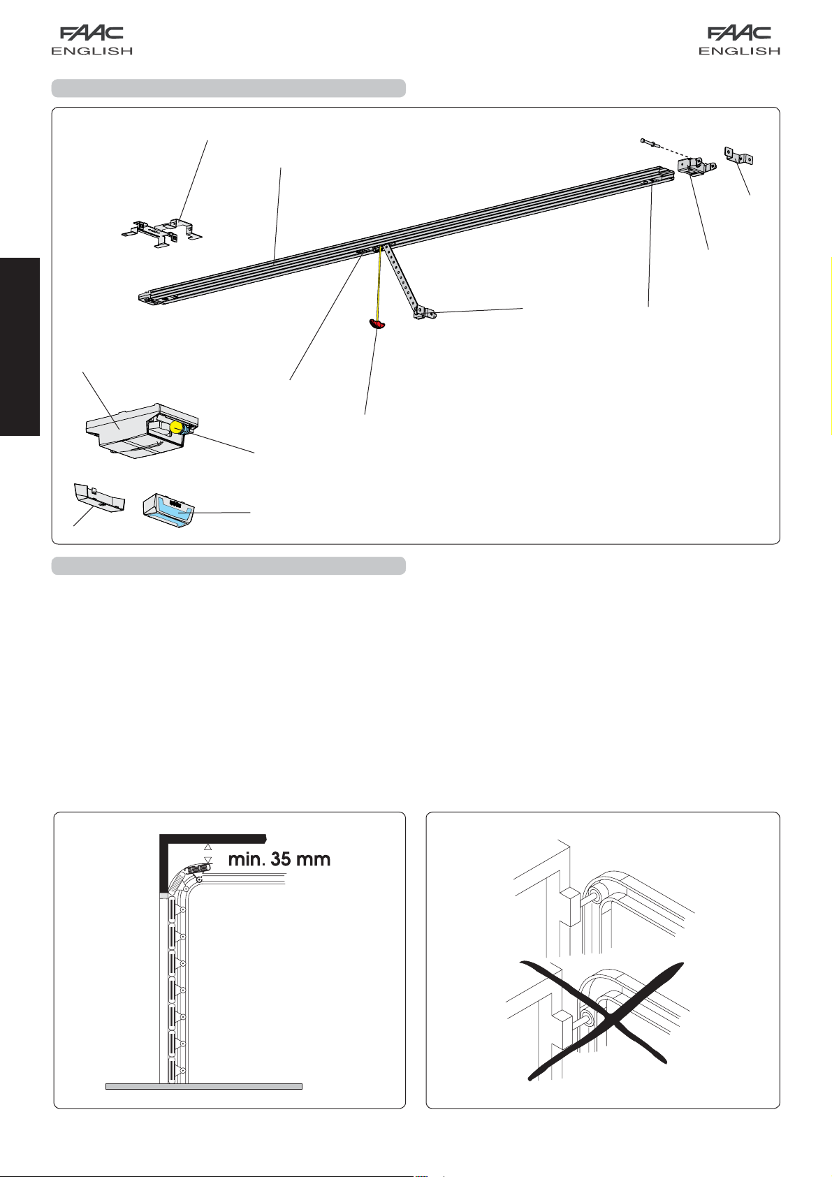
4. DESCRIPTION Ceiling lamp Rear door Courtesy light Plastic housing for D1000 operator Rear fitting Sliding guide Drive carriage Release knob Door fitting bracket Transmission unit Front fitting and chain tensioner Fig. 3 Front fitting bracket 5. PRELIMINARY CHECKS have been installed.
-
Page 8: Assembly
2) Slide the transmission unit (Fig.7 ref. A) along the whole sliding 6. ASSEMBLY guide, until it is near the front terminal, the one opposite the 6.1. Sliding guide drive coupling. 3) Assemble the front fitting (Fig. 7 ref. B) to the transmission unit If you use a sliding guide in two pieces, you must assemble it, (Fig.
-
Page 9: External Release (Optional)
6.3. External release (optional) 7.1. Sliding guide If the external release system has to be installed, the cable When you have finished the preliminary assembly operations, must be placed in its seat before beginning to install. you can begin installing the sliding guide, as follows: 1) Release the carriage (see par.
-
Page 10: On-Door Fitting
Lift the sliding guide until the rear fitting is at the same level Position the fitting on the door so that the through-element as the front fitting, or until you reach the same inclination as of the release cable is facing toward the left side of the door the door’s horizontal rail. -
Page 11: Operator
7.3. Operator When you have assembled the rear fitting to the sliding guide and finished installing the sliding guide, you can install the operator: 1) While keeping the operator inclined at 15/20° (Fig. 20), insert the gearmotor shaft in the coupling on the rear fitting of the sliding guide and make the fins (Fig.
-
Page 12: E1000 Control Board
8. E1000 CONTROL BOARD 8.1. Technical specifications 230 / 50 Supply voltage (V ~ / Hz.) Power supply to accessories (Vdc) Accessories max. load (mA.) -20 / +55 Operating ambient temperature (°C) for receiver boards XF433 / Quick-fit connector XF868 and battery module Automatic / Semiautomatic Operating logics Open/Stop/Safety devices/Fail-…
-
Page 13: Courtesy Light
During the closing manoeuvre, it opens — The D1000 operator has a cable with a two-pole plug for 230 the door. Vac power supply. — To connect the external controls, safety devices and signals, If, during closure, an obstacle is detected more than break open the pre-holed element (Fig.
-
Page 14: Programming
— the force required to move the door. 11. PROGRAMMING — the slow-down points. 11.1. Setting the board — the opening and closing stop points. — the pause time (in automatic logic). Set the appliance with Dip-Switch DS1 to obtain the operation you require, referring to chapter 8.4.
-
Page 15
During these 5 seconds, in order to lighten the load on the 1) Give the 1st OPEN command: the operator performs a release system, you can send OPEN pulses within a time interval deceleration closing manoeuvre until it detects the stop of 2 seconds from each other, in order to reverse the carriage. -
Page 16: Pre-Flashing
11.3 Pre-flashing The pre-flashing function can be enabled and disabled (following an OPEN command, the unit activates the flashing lamp for 5 seconds before it starts the movement). Procedure: 1) Press and hold down the SET UP push-button. 2) Press the OPEN push-button too after about 3 seconds. If the SET UP LED goes ON, pre-flashing was activated, if instead, it stays OFF, pre-flashing was disabled.
-
Page 17: Memory Storage Of Radio Controls Lc (For Some Markets Only)
— Quickly press twice in succession the memory stored radio control push-button All codes of radio controls stored as OPEN A and OPEN B will be deleted. The automated system performs one opening operation. 13. START-UP Make sure that the automated system is free of any obstacle created by persons or things.
-
Page 18: Parachute Cables
16 . REPAIRS — House the control unit as shown in Fig. 36. — First hook on the two fastening clips on the coupling on the For repairs, contact FAAC’s authorised Repair Centres.17.1. base. Central support — Then press lightly until you can hear the hooking snap sound.
-
Page 19: Troubleshooting
18 . TROUBLESHOOTING Trouble Possible causes Solution When the learning procedure is started, The STOP and FSW safety devices are the SET UP LED flashes but the automated enabled also during the learning stage. system does not perform any Non-connection or wrong connection manoeuvre prevents the operator from working Check the LEDs’…
This manual is also suitable for:
D600
![]()
FAAC D600/D1000 Привод для гаражных ворот — Инструкция по установке и эксплуатации в формате pdf. Руководства по установке, настройке и эксплуатации оборудования.
Дата добавления: 10.08.2009
Размер файла: 1.7Mb
Формат файла: pdf
Просмотров: 4816
Загрузок: 1479
Дополнительная информация
Отзывы и комментарии
Отзывы и комментарии к материалу «FAAC D600/D1000 Привод для гаражных ворот — Инструкция по установке и эксплуатации».

Index
GENERAL SAFETY INSTRUCTIONS FOR INSTALLATION AND MAINTENANCE ………………………………… p. 2
TOOLS AND MATERIALS ………………………………………………………………………………………………………… p. 2
DECLARATION OF CONFORMITY ………………………………………………………………………………………….. p. 3
WARNINGS FOR THE INSTALLER ……………………………………………………………………………………………… p. 3
1. DIMENSIONS ……………………………………………………………………………………………………………………. p. 4
2. TECHNICAL SPECIFICATIONS ……………………………………………………………………………………………. p. 4
3. ANCILLARY ELECTRICAL EQUIPMENT ………………………………………………………………………………… p. 4
4. DESCRIPTION ………………………………………………………………………………………………………………….. p. 5
5. PRELIMINARY CHECKS ……………………………………………………………………………………………………… p. 5
6. ASSEMBLY ………………………………………………………………………………………………………………………. p. 6
6.1. Sliding guide ………………………………………………………………………………………………………………….. p. 6
ENGLISH
6.2. Rear fitting …………………………………………………………………………………………………………………….. p. 6
6.3. External release (optional) ……………………………………………………………………………………………… p. 7
7. INSTALLATION ………………………………………………………………………………………………………………….. p. 7
7.1. Sliding guide ………………………………………………………………………………………………………………….. p. 7
7.2. On-door fitting ……………………………………………………………………………………………………………….. p. 8
7.3. Operator ……………………………………………………………………………………………………………………….. p. 9
7.4. Releasing the automated system ……………………………………………………………………………………. p. 9
7.5. External release ………………………………………………………………………………………………………………. p. 9
8. E1000 CONTROL BOARD …………………………………………………………………………………………………… p. 10
8.1. Technical specifications ………………………………………………………………………………………………………….. p. 10
8.2. E1000 board components ………………………………………………………………………………………………………… p. 10
8.3. Terminal-boards and connectors ………………………………………………………………………………………………. p. 10
8.4. DS1 Programming dip-switches ………………………………………………………………………………………………. p. 10
8.5. Operating logics …………………………………………………………………………………………………………………….. p. 10
9. COURTESY LIGHT ……………………………………………………………………………………………………………… p. 11
10. CONNECTIONS ……………………………………………………………………………………………………………… p. 11
11. PROGRAMMING ……………………………………………………………………………………………………………. p. 12
11.1. Setting the board …………………………………………………………………………………………………………………… p. 12
11.2. Learning (SET UP) …………………………………………………………………………………………………………………….. p. 12
11.3. Pre-flashing …………………………………………………………………………………………………………………………… p. 14
12. MEMORY STORAGE OF RADIO CONTROLS CODING ………………………………………………………… p. 14
12.1. Memory storage of radio controls DS …………………………………………………………………………………….. p. 14
12.2. Memory storage of radio controls SLH ……………………………………………………………………………………. p. 14
12.3. Memory storage of radio controls LC (for some markets only) ………………………………………………… p. 15
12.3.1. Remote memory storage of LC radio controls ………………………………………………………. p. 15
12.4. Radio controls deletion procedure ………………………………………………………………………………………… p. 15
13. START-UP ……………………………………………………………………………………………………………………….. p. 15
14. PARACHUTE CABLES ………………………………………………………………………………………………………. p. 16
15. MAINTENANCE ……………………………………………………………………………………………………………… p. 16
16. REPAIRS ………………………………………………………………………………………………………………………… p. 16
17. ACCESSORIES ……………………………………………………………………………………………………………….. p. 16
17.1. Central support ……………………………………………………………………………………………………………………… p. 16
17.2. Key-operated release ……………………………………………………………………………………………………………. p. 16
17.3. Safety edge CN60E ……………………………………………………………………………………………………………….. p. 16
17.4. Battery KIT ……………………………………………………………………………………………………………………………… p. 16
18. TROUBLESHOOTING ……………………………………………………………………………………………………….. p. 17
1

GENERAL SAFETY INSTRUCTIONS
FOR INSTALLATION AND MAINTENANCE
For an efficient and safe automated door, correctly observe the installation procedures and instructions for use.
Incorrect installation and use can cause serious damage to persons and property.
Carefully read the whole installation manual before you begin installing.
Do not make any modifications which are not mentioned in this manual.
Do not install the operator for uses other than those indicated.
To fasten, use the supplied accessories or, in any case, fastening systems (screws, expansion plugs, etc.) suitable for the type
of support and for the mechanical stresses exerted by the automated system.
Check if the sectional door conforms to standards EN12604 and EN 12605 (the information can be found in the documentation
accompanying the door itself). For non-EU countries, the above mentioned standards must be observed in addition to the
national standard references to obtain a suitable safety level.
Make sure that the door is correctly balanced, correctly operational, and supplied with mechanical opening stops.
When installing we advise you to:
•obtain the material and tools indicated in the following paragraph “Tools and materials” and keep them near at hand.
•use a stable support for performing operations without a floor support.
•protect your face and hands adequately before making the holes with the drill.
•do not allow children to play near during installation, use and during the automated system release manoeuvre.
•remove any debris and objects which could hamper movement, before powering up the system.
•remove the door’s closing mechanism to ensure the door is closed by the automatism.
•stick on the warning stickers as shown in the instruction.
•install the manual release devices at a height of not over 180cm.
•install the external control devices at a height of not below 150cm, clear of the door movement area, but in a position
enabling visual control of the area.
When you have finished installing we advise you to:
•check if the anti-crushing device is able to detect a 50mm high object on the ground and if a weight of 20 kg applied to the
door, causes the opening movement to stop.
•make sure that no part of the door interferes with public spaces such as pavements and/or roads.
•Use the automated system observing the instructions in the “User’s guide”.
•Fill in, keep and update the maintenance register.
ENGLISH
•The D1000 automated system does not require periodic replacement of parts.
•Every month, run a functional check of the safety devices and of the anti-crushing system: a non-deformable object with
a height of 50 mm laid on the ground, must be correctly detected.
IMPORTANT! DANGER OF CRUSHING.
•If the power cable of operator D1000 is damaged, it must be replaced by qualified personnel, using a new cable of the same
type. Do not use different power cables.
TOOLS AND MATERIALS
Tools you will require to install the D1000 operator:
•a hammer drill with relevant wall and iron bits
•screwdrivers for cross-head and cut-head screws
•two flat wrenches for 13 mm hexagon head screws
Material required for installing the D1000 operator and the relevant accessories (if present):
•cable 2×0,5 mm2 (emitting photocells, pulse generators for opening movement and stop)
•cable 4×0.5 mm2 (receiver photocells)
•cable 2×0.75 mm2 (flashing lamp)
•cable 2 x 1.5 mm2 (power)
Use cables with an adequate degree of insulation.
The electric system must conform to the prescriptions in the chapter entitled “Warnings for the installer”.
The 230 Vac power cable must be laid and connected by a qualified installation technician. Arrange for a 2P 10A 250 V
socket to be installed near the operator.
Lay the cables in the appropriate pipes and do not allow loose cables to come into contact with moving parts of the
automated system and the door.
2
CE DECLARATION OF CONFORMITY FOR MACHINES
(DIRECTIVE 98/37/EC)
Manufacturer: FAAC S.p.A.
Address: Via Benini, 1 — 40069 Zola Predosa BOLOGNA — ITALY
Declares that: Operator model. D1000 with E1000 unit,
• is built to be integrated into a machine or to be assembled with other machinery to create a machine under
the provisions of Directive 98/37/EC;
• conforms to the essential safety requirements of the other following EEC directives:
73/23/EEC and subsequent amendment 93/68/EEC.
89/336/EEC and subsequent amendment 92/31/EEC and 93/68/EEC
Furthermore, the manufacturer declares that the machinery must not be put into service until the machine into
which it will be integrated or of which it will become a component has been identified and its conformity to the
conditions of Directive 89/392/EEC and subsequent modifications assimilated in Italian National legislation under
ENGLISH
Presidential Decree No. 459 of 24 July 1996 has been declared.
Bologna, 01 January 2006
The Managing Director
A. Bassi
WARNINGS FOR THE INSTALLER
GENERAL SAFETY OBLIGATIONS
1) ATTENTION! To ensure the safety of people, it is important that you read
all the following instructions. Incorrect installation or incorrect use of the
product could cause serious harm to people.
2) Carefully read the instructions before beginning to install the product.
3) Do not leave packing materials (plastic, polystyrene, etc.) within reach
of children as such materials are potential sources of danger.
4) Store these instructions for future reference.
5) This product was designed and built strictly for the use indicated in this
documentation. Any other use, not expressly indicated here, could
compromise the good condition/operation of the product and/or be
a source of danger.
6) FAAC declines all liability caused by improper use or use other than
that for which the automated system was intended.
7) Do not install the equipment in an explosive atmosphere: the presence
of inflammable gas or fumes is a serious danger to safety.
 The mechanical parts must conform to the provisions of Standards EN
12604 and EN 12605.
For non-EU countries, to obtain an adequate level of safety, the
Standards mentioned above must be observed, in addition to national
legal regulations.
9) FAAC is not responsible for failure to observe Good Technique in
the construction of the closing elements to be motorised, or for any
deformation that may occur during use.
10) The installation must conform to Standards EN 12453 and EN 12445.
For non-EU countries, to obtain an adequate level of safety, the
Standards mentioned above must be observed, in addition to national
legal regulations.
11) Before attempting any job on the system, cut out electrical power .
12) The mains power supply of the automated system must be fitted with
an all-pole switch with contact opening distance of 3mm or greater. Use
of a 6A thermal breaker with all-pole circuit break is recommended.
13) Make sure that a differential switch with threshold of 0.03 A is fitted
upstream of the system.
14) Make sure that the earthing system is perfectly constructed, and connect
metal parts of the means of the closure to it.
15) The safety devices (EN 12978 standard) protect any danger areas
against mechanical movement Risks, such as crushing, dragging, and
shearing.
16) Use of at least one indicator-light (e.g. FAACLIGHT ) is recommended
for every system, as well as a warning sign adequately secured to the
frame structure, in addition to the devices mentioned at point “15”.
17) FAAC declines all liability as concerns safety and efficient operation of
the automated system, if system components not produced by FAAC
are used.
18) For maintenance, strictly use original parts by FAAC.
19) Do not in any way modify the components of the automated
system.
20) The installer shall supply all information concerning manual operation
of the system in case of an emergency, and shall hand over to the user
the warnings handbook supplied with the product.
21) Do not allow children or adults to stay near the product while it is
operating.
22) Keep remote controls or other pulse generators away from children, to
prevent the automated system from being activated involuntarily.
23) Transit under the door must occur only when the automated system
has stopped.
24) The user must not attempt any kind of repair or direct action whatever
and contact qualified personnel only.
25) Maintenance: check at least every 6 months the efficiency of the
system, particularly the efficiency of the safety devices (including, where
foreseen, the operator thrust force) and of the release devices.
26) Anything not expressly specified in these instructions is not permitted.
3
AUTOMATED SYSTEM D1000
These instructions apply to model FAAC D1000.
The D1000 automated systems make it possible to automate
balanced sectional doors of single garages for residential
use.
They consist of an electro-mechanical operator, electronic
control unit and courtesy light built into a single unit. This unit is
fitted to the ceiling and opens the door by means of a transmission
chain or belt.
The system is non-reversing and, therefore, the door locks
mechanically when the motor is not operating and, consequently,
no lock is necessary; two manual releases, one on the inside
and one on the outside (optional) make it possible to move the
door in case of a power cut or fault.
The operator is supplied with an electronic device that detects
the presence of an obstacle that would hinder door movement
— the device prevents crushing or lifting.
This instruction refers to the operator with chain drive, but the
same procedures, regulations and application limits apply also
to the belt driven operator.
The D1000 automated systems were designed and built for
indoor use and to control vehicle access. Do not use them for
any other purpose.
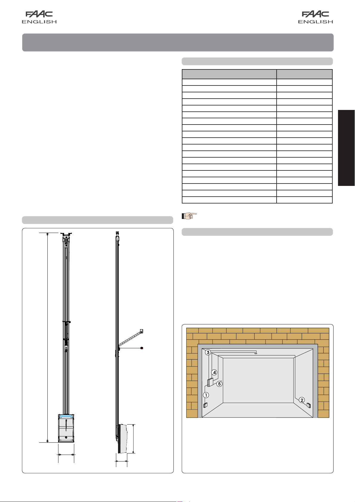
1. DIMENSIONS
Dimensions in mm.
2. TECHNICAL SPECIFICATIONS
Model D1000
Power supply (V ~ / 50 Hz.) 230
Electric motor (Vdc) 24
Maximum absorbed power (W) 350
Thrust force (N) 600/1000
Type of use continuous
Maximum dimensions from ceiling (mm) 35 (Fig. 4)
Courtesy light (V ~/W) 230 / 40 max.
Courtesy light timer (sec) 120
Standard speed with no-load carriage (m/min)
Slow speed with no-load carriage (m/min) 4,5
Carriage deceleration speed (m/min) 1,1
Noise at standard speed (dB(A)) 52
Travel length at deceleration
Intrinsic safety device Category 2
Maximum sectional door width (mm) 5000
Maximum sectional door height (mm) See useful travel
Sliding guide useful travel (mm) 2500 — 3100 — 3800
Protection class For indoor use only (IP20)
Operating ambient temperature (°C) -20 / +55
Varies according to set-up
8,9
The level of noise emission of operator D1000, referred
to the work station, is 52 dB(A).
3. ANCILLARY ELECTRICAL EQUIPMENT
Prepare the electric system in keeping with the instructions in
the chapter entitled “Warnings for the installer”.
When you have finished installing, check if any external pipes
or cables can come into contact with moving parts.
Install the fixed control points at a minimum height of 150 cm,
clear of the door movement area, but in a position enabling
visual control of that area.
ENGLISH
Fig. 1
2168 / 2768 / 3368
200
145
360
Cable 2 x 0.5 mm2 (TX photocell)
Cable 4 x 0.5 mm
2
(RX photocell)
Power pipe (230V)
Low voltage pipe
Cable 2 x 1.5 mm
4
2
(power)
Fig. 2
4. DESCRIPTION
ENGLISH
5. PRELIMINARY CHECKS
— The structure of the door must be suitable for fitting automation.
In particular, check that the door dimensions conform to
those indicated in the technical specifications, and that it is
sufficiently sturdy.
— Check if the door conforms to standards EN12604 and
EN12605.
— As it moves, the door must not encroach public areas
dedicated to pedestrian or vehicular transport.
— Check the efficiency of the door bearings and joints.
— Make sure that the door is friction-free. If necessary clean
and lubricate the guides with silicone based products, but do
not use grease, and, in any event, follow the manufacturer’s
instructions.
— Check correct balance and if the opening mechanical stops
Ceiling lamp
Rear door
Courtesy light
Plastic housing for D1000 operator
Rear fitting
Sliding guide
Drive carriage
Release knob
Door fitting bracket
Transmission unit
Front fitting and chain tensioner
Front fitting bracket
have been installed.
— Remove the door’s existing closing mechanism to ensure the
door is closed by the automated system.
— Make sure there is a clearance of at least 35 mm between the
ceiling and the highest sliding point of the door (Fig.4).
— Check if the upper guide roller of the sectional door is in the
horizontal part of the guide while the door is closed (fig. 5).
Fig. 3
Fig. 5Fig. 4
5

6. ASSEMBLY
6.1. Sliding guide
If you use a sliding guide in two pieces, you must assemble it,
as explained below. If you have a pre-assembled guide, go
on to paragraph 6.2.
1) Assemble the two pieces of the sliding guide, fitting them
in the central joint (Fig. 6 ref. A) until they come to a stop
against the metal reference reliefs (Fig. 6 ref. B). To facilitate
engaging the sliding guide, we advise you to insert it in the
central joint, compressing it as shown in Fig. 6 ref. C. Do not
use tools which could deform the guide or joint.
2) Slide the transmission unit (Fig.7 ref. A) along the whole sliding
guide, until it is near the front terminal, the one opposite the
drive coupling.
3) Assemble the front fitting (Fig. 7 ref. B) to the transmission unit
(Fig. 7 ref. A).
4) Apply slight tension to the chain, tightening the nut (Fig. 7
ref. C.).
5) Place the sliding guide on the side (Fig. 8).
6) Push the carriage toward the drive clutch unit (Fig.8
ref. C).
7) Adjust the tensioner (fig. 8 ref. A) so that the central zone of
the loop, formed by the top branch of the chain, coincides
with about the mid-point of the sliding guide (Fig. 8 ref. B).
Attention: too much tension can cause damage to the
transmission and drive clutch units.
6.2. Rear fitting
Before securing the sliding guide to the ceiling, assemble the
rear fitting in the seat of the drive clutch unit and fasten the
screws as shown in Fig. 9 ref. .
ENGLISH
Fig. 6
Fig. 7 Fig. 9
Fig. 8
6
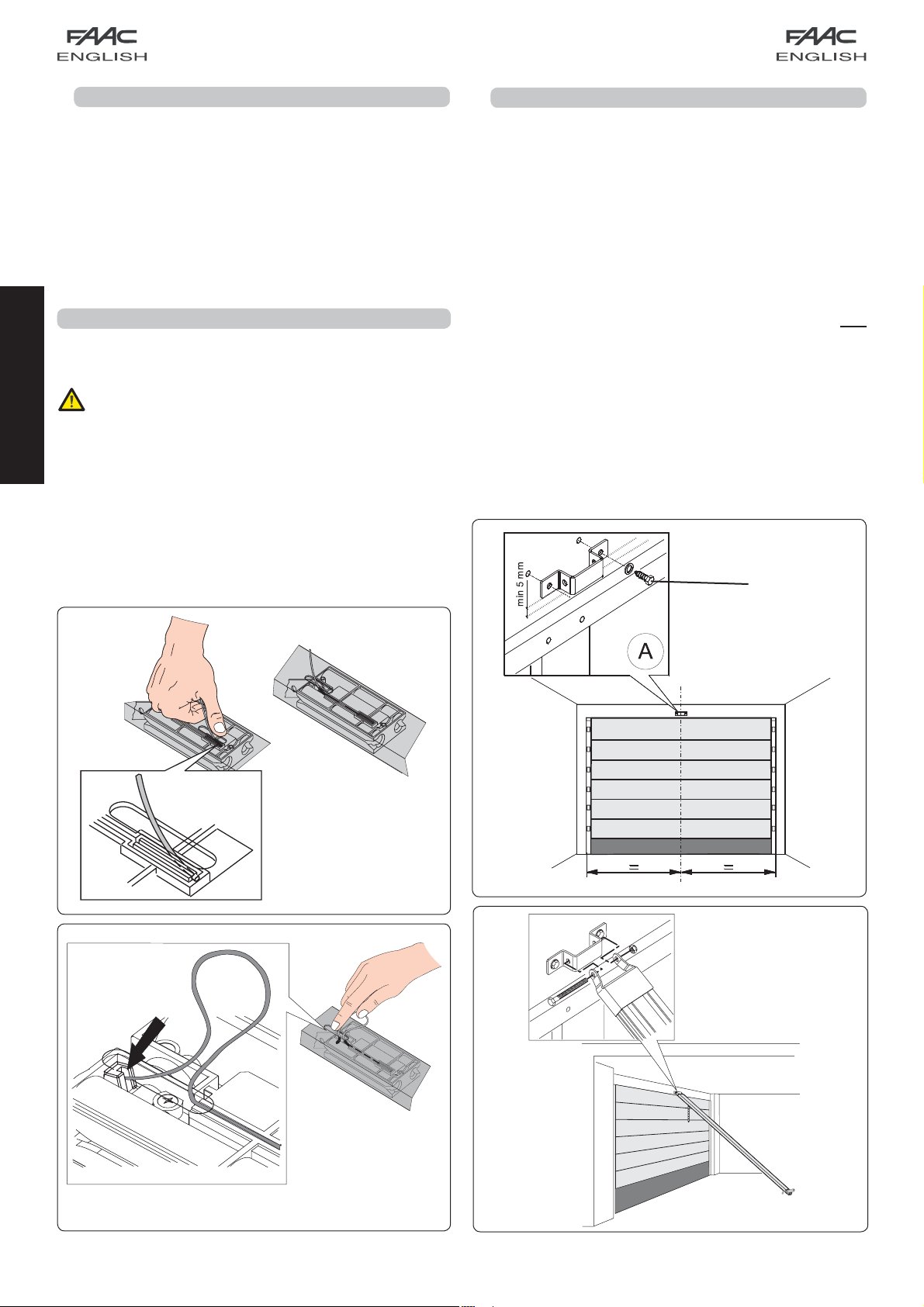
6.3. External release (optional)
If the external release system has to be installed, the cable
must be placed in its seat before beginning to install.
1) Release the carriage (see par. 7.4 point 3), and take it to
the slot on the top of the sliding guide.
2) Fit the cable terminal on the red seat (Fig. 10).
3) Take the carriage back toward the drive clutch unit until
the through-hole on the carriage coincides with the slot,
and fit the unsheathed cable (Fig. 11).
4) Fully withdraw the cable from the bottom of the
carriage.
5) Wind the cable around itself to prevent it getting in the way
while the sliding guide is being installed.
7. INSTALLATION
— To ensure you work in safe conditions, we advise you
to install the operator while keeping the door fully
closed.
— Use all the specified anchorage points.
— The fastening systems must be suitable for the type of
support and sufficiently tough.
ENGLISH
— Protect your hands and face adequately while drilling
the holes.
— Read this chapter to the full before you begin
installing.
7.1. Sliding guide
When you have finished the preliminary assembly operations,
you can begin installing the sliding guide, as follows:
1) On the architrave, mark a line corresponding to the vertical
mid-point of the door (Fig. 12).
2) On the architrave, mark a horizontal line corresponding to
the maximum height reached by the door during movement
(see Fig. 4).
3) Position the securing bracket of the front fitting, so that the
lower edge is at least 5 mm above the intersection point of
the lines and centred with respect to the vertical line (Fig.
12). Also refer to paragraph 7.2 for correct positioning of the
bracket with respect to the fitting point on the door.
4) Mark the two securing points.
5) Next, drill and install, using the screws (ref. Fig. 12) NOT
supplied.
6) Position the sliding guide on the floor, perpendicular with
respect to the door.
7) Lift guide off the front fitting and assemble the latter with
the securing bracket, using the through screw and nut (Fig.
13).
Fig. 10
Fig. 12
Fig. 11
Fig. 13
7
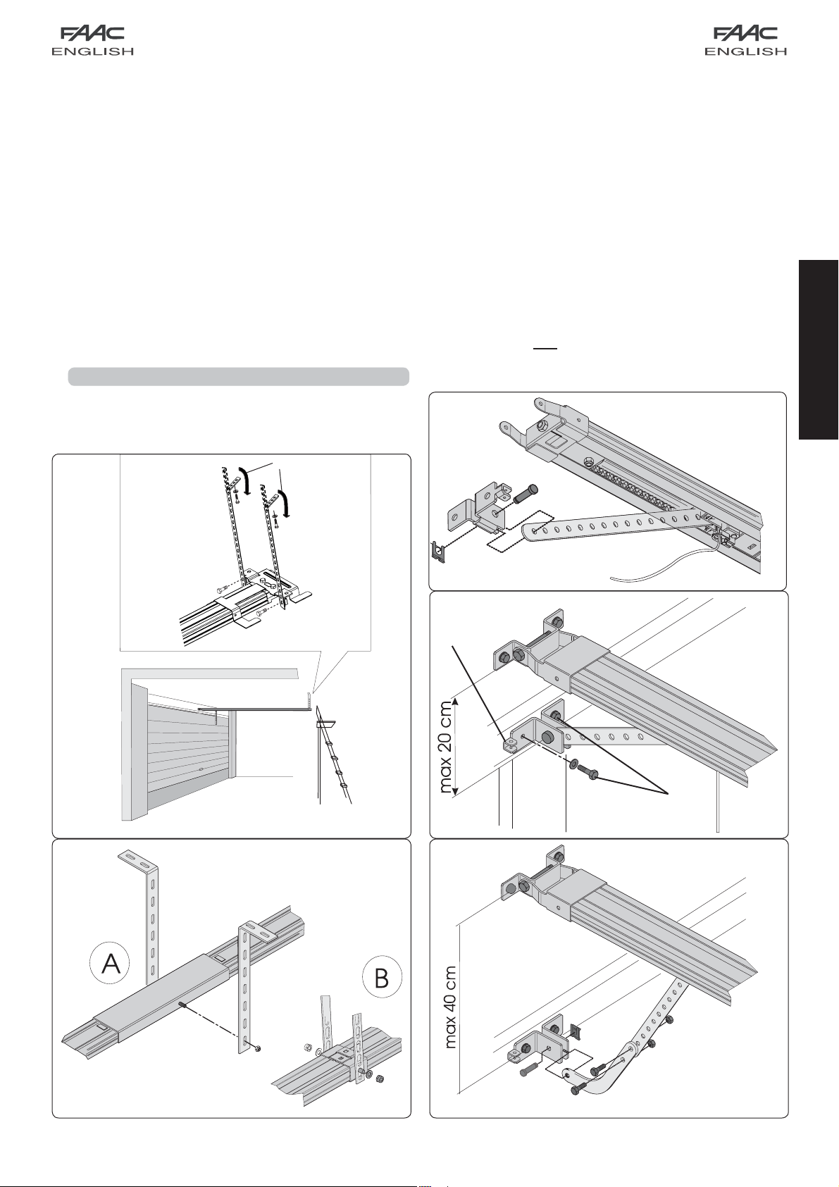
Lift the sliding guide until the rear fitting is at the same level
as the front fitting, or until you reach the same inclination as
the door’s horizontal rail. If you are securing directly to the
ceiling, go to point 12.
9) Measure the distance between the ceiling and the
between-axis position of the nuts securing the rear fitting.
10) Bend the supplied brackets according to the measurement
you have taken (measure starting from the centre of the
bracket’s first slot).
11) Fit the brackets on the rear fitting and re-position the sliding
guide (Fig. 14).
12) Mark the on-ceiling securing points of the rear fitting and drill
(taking care to protect the sliding guide). Finish installing the
guide.
13) If using a two-piece guide with central joint (Fig. 15 ref. A) or
the central support for a single rail (Fig. 15 ref. B — optional),
secure to the ceiling, using the brackets and proceed
according to steps 9, 10 and 12 (Fig. 15).
7.2. On-door fitting
1) Assemble the fitting with the carriage rod (Fig. 16).
Position the fitting on the door so that the through-element
of the release cable is facing toward the left side of the door
(ref. Fig. 17).
2) Close the door and take the carriage near to it.
3) Position the fitting on the door, centred with respect to its
mid-point.
4) Make sure that the distance between the between-centres
of the securing holes of the front fitting and the on-door fitting
does not exceed 20 cm (Fig. 17). To ensure correct operation
of the automated system, we advise you to avoid arm
inclinations of over 30° compared to the sliding guide.
If using the curved arm for sectional doors (optional), carry
out the assembly with the straight arm of the carriage as
shown in Fig. 18. To improve efficiency of the anti-crushing
system, we advise you to secure the fitting on the sectional
door as low as possible, without, however, exceeding the
distance of 40 cm from the operator’s front fitting.
5) Mark, drill and secure the fitting to the door, using the screws
(ref. Fig. 17) NOT supplied.
Fig. 16
ENGLISH
Fig. 14
Fig. 17
Fig. 15 Fig. 18
8
7.3. Operator
When you have assembled the rear fitting to the sliding guide
and finished installing the sliding guide, you can install the
operator:
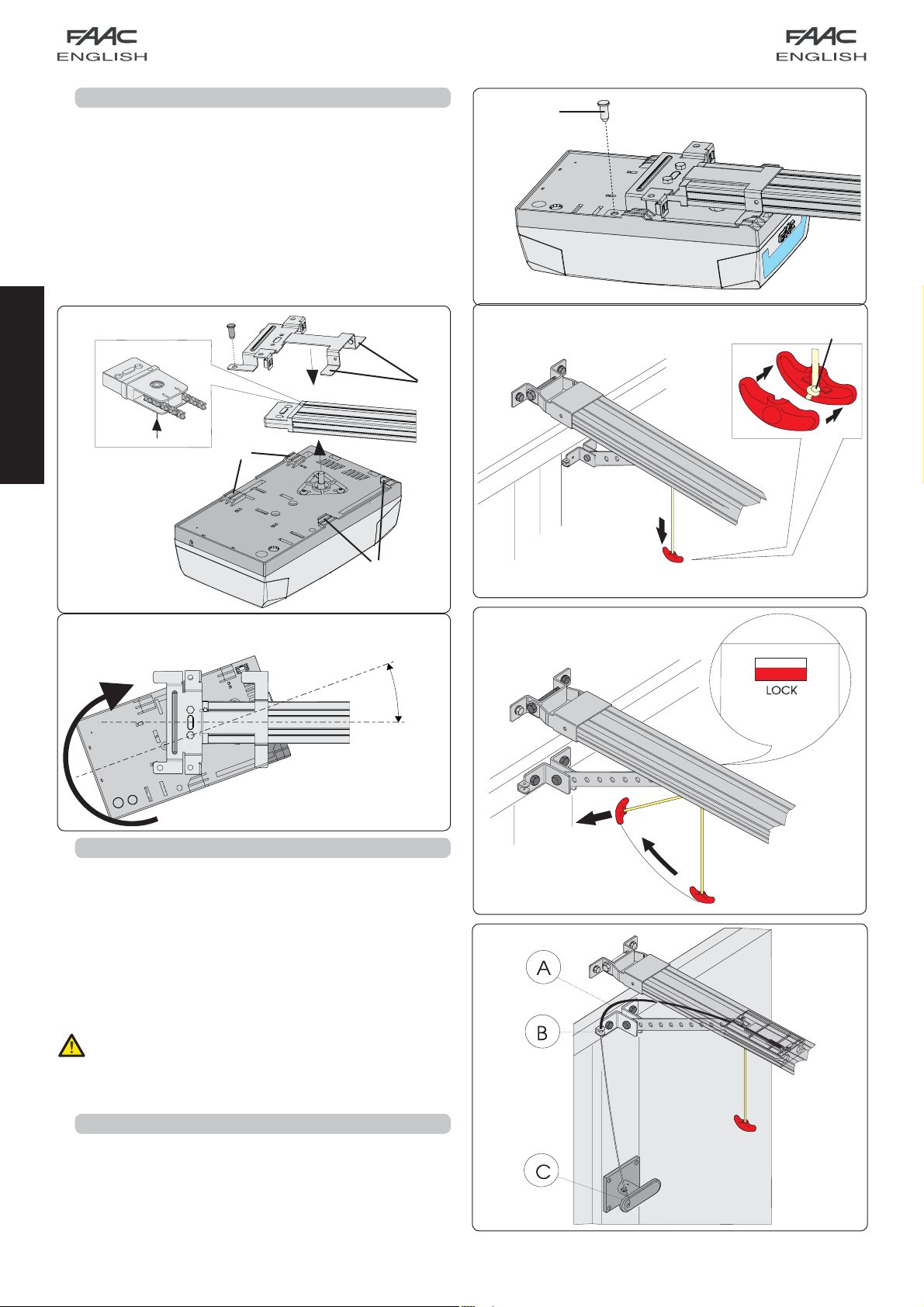
1) While keeping the operator inclined at 15/20° (Fig. 20), insert
the gearmotor shaft in the coupling on the rear fitting of the
sliding guide and make the fins (Fig. 19 ref. ) near to the
seats at the bottom of the operator base (Fig. 19 ref. ).
2) Turn the operator in the direction of Fig. 20 until you reach
position of Fig. 21, and fit the pin in the hole of the rear fitting
(Fig.21 ref. ).
Fig. 21
ENGLISH
Fig. 19
15°/20°
Fig. 20
7.4. Releasing the automated system
1) Define the height of the release knob, taking into account
that it must not be over 180 cm off the ground, and cut off
the excess section of rope.
2) Make a knot at the end of the rope and assemble the release
handle (Fig. 22).
3) Pull the release handle down and check if the door can be
moved manually (Fig. 22).
4) Pull the release handle horizontally in the direction of the
door (Fig. 23). Check if, when the handle is released, the
LOCK window under the carriage is red. Move the door
manually until you find the carriage’s hook-on point.
Make sure that there are no persons, animals or objects in
the door movement area during the release manoeuvre.
Fig. 22
Fig. 23
7.5. External release
If the automated system has an external release, finish
installing (see par. 6.3):
1) Cut the cable sheath to size (Fig. 24 ref. A).
2) Fit the cable inside the sheath and route it through the eyelet
of the door fitting (Fig. 24 ref. B).
3) Cut the cable to size and assemble it together to the internal
lever of the release handle (Fig. 24 ref. C).
Fig. 24
9

8. E1000 CONTROL BOARD
8.1. Technical specifications
Supply voltage (V ~ / Hz.)
Power supply to accessories (Vdc)
Accessories max. load (mA.)
Operating ambient temperature (°C)
Quick-fit connector
Operating logics
Terminal-board connections
Courtesy light timer (min.)
for receiver boards XF433 /
XF868 and battery module
Automatic / Semiautomatic
Open/Stop/Safety devices/Fail-
safe/Flashing lamp 24 Vdc
8.2. E1000 board components
J1 Low voltage inputs/accessories terminal board
Quick-fit connector for receivers XF433 or XF868
J2
J3 230V power supply input terminal board
J4 Connector for transformer primary winding
J5 Courtesy light terminal-board
J7 Connector for transformer secondary winding
J8 Motor output connector
J12 Battery module connector
OPEN A Radio signal programming push-button
OPEN B Radio signal programming push-button
OPEN OPEN push-button
SETUP SET-UP push-button
DS1 Programming dip-switch
LD1 Signalling LED: OPEN input
LD2 Signalling LED: STOP input
LD3 Signalling LED: FSW input
LD4 Signalling LED: SET UP cycle
LD5 LED signalling memory-storage: radio channel OPEN A
LD6 LED signalling memory-storage: radio channel OPEN B
TR1 Closing force adjustment
TR2 Opening force adjustment
230 / 50
24
200
-20 / +55
2
J1
LD3
LD1
LD2
SET UP
LD4
OPEN
J8
TR1
TR2
DS1
J2
LD5
J7
J12
OPEN BOPEN A
J5
LD6
J3
J4
Fig. 25
Fail Safe
If activated, it enables the photocell operating test before every
movement.
Operating logics
For doors with an irregular movement, it reduces the sensitivity of
the anti-crushing device to prevent unwanted action by it.
ENGLISH
8.3. Terminal-boards and connectors
Description Connected device
OPEN A
STOP
Command device with N.O. contact
(see chap. OPERATING LOGICS)
Device with N.C. contact which stops the
automated system
Negative for OPEN A and STOP devices
FSW
LAMP
-TX FSW
Closing safety device with N.C. contact (see
chap. OPERATING LOGICS)
OPEN COLLECTOR 24 Vdc 100 mA. output for
flashing lamp
Negative for powering safety accessories (FAIL
SAFE function)
Negative for powering accessories
+24 Vdc for powering accessories
8.4. DS1 Programming dip-switches
No. Function OFF ON
1 Fail Safe Enabled
Not enabled
2 Anti-crushing sensitivity Low High
3 Force adjustment Automatic Manual
4 Carriage speed High Low
Manual adjustment of force
If you wish to adjust force manually, before learning, turn ON
switch No. 3 of DS1, and manually adjust the thrust force with TR1
(closure) and TR2 (opening). Maximum available thrust is 1000N.
8.5. Operating logics
Logic A (automatic)
Status Open (pulse) Stop Fsw
CLOSED
OPENING No effect Locks (2) No effect (1)
OPEN IN
PAU S E
CLOSING Reverses motion Locks (2) Reverses motion
LOCKED Closes No effect (2) No effect (1)
Opens and closes
after pause time
Resumes counting of
pause time (1)
No effect (2) No effect
Locks (1)
Resumes counting of
pause time (1)
Logic E (semi-automatic)
Status Open (pulse) Stop Fsw
CLOSED Opens No effect (2) No effect
OPENING Locks Locks (2) No effect (1)
OPEN Closes No effect (2) No effect (1)
CLOSING Reverses motion Locks (2) Reverses motion
LOCKED Closes No effect (2) No effect (1)
10
(1) Prevents closing if pulse is maintained.
(2) Prevents closing and/or opening if pulse is
maintained.
During the opening manoeuvre, the
anti-crushing device causes an immediate
stop. During the closing manoeuvre, it opens
the door.
If, during closure, an obstacle is detected more than
three consecutive times, the automated system
considers this distance as the new closing contact point
and goes into closed status. To restore the correct
positions, remove the obstacle and command a new
cycle: at the next closure, the automated system will
advance at low speed until it detects the contact point.
9. COURTESY LIGHT
— The courtesy light stays lighted for 2 minutes after the end of
the manoeuvre (cannot be modified).
ENGLISH
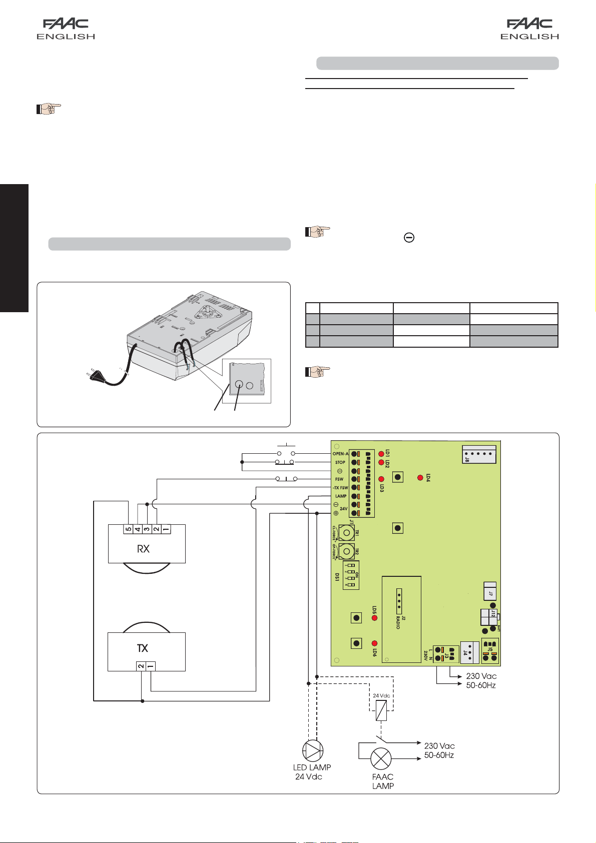
10. CONNECTIONS
IMPORTANT: Before attempting any work on the board
(connections, maintenance), always cut off power.
— To prevent any electric noise whatever, use separate sheaths
for powering the network, signals and accessories.
— The D1000 operator has a cable with a two-pole plug for 230
Vac power supply.
— To connect the external controls, safety devices and signals,
break open the pre-holed element (Fig. 26 ref. ).
— To connect the safety edge (see par. 18.3), break open the
pre-holed element (Fig. 26 ref. ).
— Make the electrical connections, referring to Fig. 27.
If the STOP input is not used, jumper connect the input
to the terminal
If the photocells are not used, connect the FSW
input to terminal -TX FSW.
Inputs status leds:
LD Meaning OFF ON
1 Input status OPEN Not enabled Enabled
2 Input status STOP Enabled Not Enabled
3 Input status FSW
.
Safety devices engaged Safety devices disengaged
Fig. 26
The automated system stopped and at rest is indicated
in bold for each input.
OPEN A
STOP
OTHER SAFETY DEVICES
11
Fig. 27
 Loading…
-
Chamberlain
3130 1/3 HP
The Chamberlain Group, Inc.845 Larch AvenueElmhurst, Illinois 60126-1196www.liftmaster.comGARAGE DOOR OPENERModelsOwner’s Manual■ Please read this manual and the enclosed safety materials carefully!■ Fasten the manual near the garage door after installation.■ The door WILL NOT CLOSE unless the Protector System� …
3130 1/3 HP Garage Door Opener, 36
-
Chamberlain
LA500
Solar Gate acceSS SyStem Daily cycle chartThe LA500 Solar Gate Access System utilizes an innovative Power Management System to deliver power when needed most for operating a gate while minimizing power consumption at all other times. Power is provided to the gate operator via batteries. The batteries are charged from a …
LA500 Garage Door Opener, 1
-
Marantec
M4900e
32Part#: 80401 Printed in U.S.A. Version: November 24, 2008 This productcompliles with the 325 regulations effective january 1,1993Owner’s Manual contains:Installation, operating, maintenance & warranty instructions.For residential use only.Digital Intelligence for the GarageMarantec America Corpora …
M4900e Garage Door Opener, 16
-
Genie
GCL-J
www.GenieCompany.com/commercial | 800.843.4084GCL-J operators are covered by the following U.S. patents: 6737823, 7878931, 8014966, 8113263The GCL-J is designed for high or full-lift sectional and rolling doors that have a 30-cycle/hour or less duty requirement. Advanced features and robust mechanical design combin …
GCL-J Garage Door Opener, 2
-
Beninca
MB
L8542335Rev. 05/05/04 MB/MBEAUTOMAZIONE PER CANCELLI A BATTENTEAUTOMATION FOR HINGED GATES AUTOMATION FÜR TOREAUTOMATION POUR PORTAILS OUVRANTSAUTOMATIZACIÓN PARA CANCELAS DE BATIENTEAUTOMATYZACJA BRAM ROZWIERANYCHLibro istruzioni e catalogo ricambiOperating instructions and spare parts catalogueBetriebsanleitung und …
MB Garage Door Opener, 32
-
Chamberlain
RDO800-series
Installation and operating instructions for rolling door opener Model RDO800-seriesChamberlain GmbHAlfred-Nobel-Strasse 466793 SaarwellingenGermanyTEL: +49 (0) 6838/907-250FAX: +49 (0) 6838/907-179www.liftmaster.com …
RDO800-series Garage Door Opener, 24