-
Contents
-
Table of Contents
-
Bookmarks
Quick Links
ESY 1~
User Manual
Specialized
Vac stepless Controllers
for
single-phase Asynchronous Motors
on Axial & Centrifugal Fans
ON
Ventilated Heat Exchangers
Drycoolers & Air Cooled Condensers
3
YEAR
FAN speed Control Solutions
Related Manuals for SELPRO ESY 1

Summary of Contents for SELPRO ESY 1
-
Page 1
ESY 1~ User Manual Specialized Vac stepless Controllers single-phase Asynchronous Motors on Axial & Centrifugal Fans Ventilated Heat Exchangers Drycoolers & Air Cooled Condensers YEAR FAN speed Control Solutions… -
Page 2: Precautions
WARNING ! HIGH LEAKAGE CURRENT First connect to Earth ! DO NOT touch the electrical parts of the circuit when the power supply is connected under any circumstances Safety Warnings • We disclaim all responsibility for accident, loss or damage caused by the use of these appliances. These must be correctly installed by qualified personnel in conformity with their intended use and, whenever needed, must undergo correct maintenance which should be carried out while ensuring the safety of people, domestic animals and goods.
-
Page 3: Table Of Contents
ELECTRICAL CONNECTIONS ………………….Errore. Il segnalibro non è definito. 5.1. Power Supply Connection (Terminal Block M1) ……………………….7 SIGNAL CONNECTIONS for the 4 CONFIGURATIONS (ALL-in-ONE) ………………..8 6.1. OM CONFIGURATION (STANDARD SELPRO) ……………………….8 6.2. OX Configuration (on request) …………………………….8 6.3. OV Configuration (on request) …………………………….9 6.4.
-
Page 4: Ec Directives & Technical Standards
EC DIRECTIVES & TECHNICAL STANDARDS This series has been designed and manufactured for use in industrial environments, and complies therefore with the following European Directives: • Machine Directive 98/37 CE and following amendments • Low Voltage Directive (LVD) 2006/95/EC • EMC Directive 2004/108/EC Thanks to its advanced technical solutions, the ESY100 series has obtained the CE mark in compliance with the EMC (Electromagnetic Compatibility) directive 2004/108/EC also in household environment.
-
Page 5: Operating Modes And Applications
3. OPERATING MODES AND APPLICATIONS The ESY1 devices are electronic analog regulators of single-phase AC voltage, which use the phase-cutting principle (Triac) in order to vary the output active voltage applied to a resistive or inductive load. When connected to asynchronous high-slip electric motors of fans or pumps, they control their rotational speed in order to maintain the key parameter within desired values.
-
Page 6: Technical Characteristics Esy-1
4. TECHNICAL CHARACTERISTICS ESY-1 Voltage 230V ± 10 % single phase – (on request 110V — 400V Frequency 50Hz standard (60 Hz only factory calibration) OWER UPPLY Overvoltage Protection for installation Category II (4 KV) Electronic analog regulators of single-phase AC voltage, which use the phase-cutting principle (Triac) in order to vary the PERATING output active voltage applied to a resistive or inductive load.
-
Page 7
Transducer voltage supply 22V (+10/-20%) max. 25mA Transducer voltage supply 22V (+10/-20%) max. 25mA Config. + 10V Transducer voltage supply 10,0V (±1%) Output signal for slave unit: 0-10Vdc or PWM (MAX 5 modules) Transducer voltage supply 22V (+10/-20%) max. 25mA Transducer voltage supply 22V (+10/-20%) max. -
Page 8: Electrical Connections
5. ELECTRICAL CONNECTIONS Connect the controller as shown in the figure below, paying attention to the following points 5.1. Power Supply Connection (Terminal Block M1) -Before supplying power to the unit, check carefully the power connection and the efficiency of EARTH connection. -Ensure that power conductors and EARTH CABLES have a cross section suitable to the connected load.
-
Page 9: Signal Connections For The 4 Configurations (All-In-One)
— SLAVE, using the input In4 ( for 0-10V control signal) The controllers of the ESY-1/ALL-in-ONE series can be set in the following four (4) configurations, described below. The OM configuration is standard SELPRO 6.1. OM CONFIGURATION (STANDARD SELPRO) N°…
-
Page 10: Ov Configuration (On Request)
6.3. OV Configuration (on request) N° Name Function CONF. Output voltage supply + 5,0V ±1% Transducer Input 0-5 Vdc N° 1 Ground Transducer Input 0-5 Vdc N° 2 Output voltage supply + 5,0V ±1% Transducer Input NTC 10kohm N° 3 @ 25°C Ground Input N°…
-
Page 11: Electrical Connection For Slave Module/S
7. Electrical connection for Slave Module/s The controllers of the ESY-1 / ALL-in-ONE series include moreover the SLAVE-ONE power units, in the two following versions: SLAVE-SV with input for 0-10Vdc control signal SLAVE-SP with input for PWM control signal All the models of the series share the same technical characteristics and are available in different sizes: 8 A –…
-
Page 12: Connection Of Slave Modules, Sp Series (Pwm Power Units)
7.3. Connection of SLAVE modules, SP series (PWM power units) The SLAVE-SP unit allows the connection of the only PWM (PPM-Triac) control signal. The input is optimized in order to be compatible with every device having a PWM control signal, from 5V to 30V. All connected SLAVE-SP units require the same supply phase as the remote controller, which generates the PWM control signal (network synchronization) SLAVE –…
-
Page 13: Esy-1: Control & Power Card In Detail, All-In-One Version
8. ESY-1: CONTROL & POWER CARD IN DETAIL, ALL-in-ONE version Led Led Led Led MAX OUT SPadj CUT-OFF (MIN OUT ) SP1adj SP2adj Double Set-Point optional card Jumper Description ESY-1 / ALL-in-ONE & LED DIRECT-REVERSE mode selection VAC Output at SET-POINT CUT-OFF / MIN OUT selection EXTRA-power control Output Power supply O.K.
-
Page 14: Led Signals
LED signals 8.2. The cards present LED signals, which point out the state and the operation of the controller. The LED signals of the complete version ESY-1 / ALL-in-ONE are shown in the table below: 230Vac Green LED Power supply O.K. Green LED SP higher than the signal value 100%…
-
Page 15: Set-Up Of Operating Limits And Parameters
9. Set-up of operating LIMITS and PARAMETERS 9.1. Available regulations in the standard ESY-1 version (ALL-in-ONE) The ESY-1 controllers present two regulation Trimmers for setting up the operating limits (MIN out / Cut-Off and MAX out), the automatic regulation performs the variations of fans speed, and a couple of 13-positions rotary switches for setting up the SET-Point of reference with ease.
-
Page 16: How To Set Up The Operating Limits For Slave-One Modules (Only Slave-Sv Version)
9.3. How to set up the operating limits for SLAVE-ONE modules (only SLAVE-SV version) The following procedures allow to set up the AC voltage limits, within which the 0-10 Vdc control signal is automatically controlled. It allows to set up manually the minimum AC output voltage MIN Vac supplied to the fan, from 20% to 90%, and permits to check: — the correct phase-cutting of the controller…
-
Page 17: Tables For The Set-Point Selection
After selecting the operating modes and setting up the operating limits, it is necessary to determine the operating point of the regulation: the SET-POINT, on the basis of the scales and ranges referring to the connected sensor (*). The Set-Point is easily and quickly fixed through the couple of 13-position rotary switches, named as follows: SP (main reference point for the regulation) and SPadj.
-
Page 18: Set Point Values, Range 0-25 Bar (Transducer 4-20 Ma)
12,74 12,83 12,93 13,02 13,11 13,21 13,30 13,40 13,49 13,58 13,68 12,69 13,73 13,16 13,21 13,30 13,40 13,49 13,58 13,68 13,77 13,87 13,96 14,05 14,15 14,20 9.5.3. Set Point values, range 0-25 bar (Transducer 4-20 mA) 0-25 bar adj. adj. 4,69 4,77 4,93…
-
Page 19: Set-Point Values, Range 0-45 Bar (Transducer 4-20 Ma)
9.5.5. Set-Point values, range 0-45 bar (Transducer 4-20 mA) 0-45 bar adj. adj. 8,45 8,59 8,87 9,15 9,43 9,72 10,00 10,28 10,56 10,85 11,13 11,41 11,55 10,00 10,28 10,56 10,85 11,13 11,41 11,69 11,97 12,26 12,54 12,82 9,86 12,96 12,82 13,10 13,38 13,67…
-
Page 20: Set-Point Values, Range 10°C To 60°C (Ntc Probe 10Kohm@25°C)
9.5.7. Set-Point values, range 10°C to 60°C (NTC probe 10kohm@25°C) 10-60 °C adj. adj. 2,00 2,50 3,00 3,50 4,00 4,50 5,50 6,00 6,50 7,00 7,50 8,00 7,50 8,00 8,50 9,00 9,50 10,50 11,00 11,50 12,00 12,50 7,00 13,00 12,50 13,00 13,50 14,00 14,50…
-
Page 21: Function Diagrams & Operating Parameters In Master & Slave Modes
10. Function diagrams & Operating parameters in MASTER & SLAVE modes Standard values of the proportional band (Pb): transducer 4-20 mA Pb=2.5 mA, transducer 0-5 Vdc Pb=0,65 Vdc, sensor NTC 10kohm@25°C Pb=7.0°C Min= Off= Vac= =fans maximum rpm — fans minimum rpm — fans off — voltage supply to the load;…
-
Page 22: Accessories
11. ACCESSORIES 11.1. Manual Remote Control Units ♦ Series of potentiometers for manual remote control Potentiometer for external remote control Manual speed setting with 0-10 Vdc Available 1 & 10 turn versions, with standard knob ∅ ∅ ∅ ∅ 22 and silk screen label Available 10 turn version, with knob ∅…
-
Page 23: Pressure Transducer For 4-20 Ma & 0-5 V
11.2 Pressure Transducer for 4-20 mA & 0-5 V Description 4-20 mA 0-5 Vdc Control signal 4 … 20 mA 0,5 … 4,5 V Power supply 8 … 28 V 5 V +/- 0,25V Range (bar) 0 … 15/25/30/45 0 … 30/45 Linearity <…
-
Page 24
TECHNICAL ASSISTANCE FORM 1. All ESY-1 equipments are guaranteed for 36 months from the date of testing. 2. The guarantee will be rendered invalid under these circumstances: • evidence of tampering with the mechanical or electrical parts • improper use •… -
Page 25
Via P. G. Piamarta, 5/11 Tel. (+39) 030.6821611 info@selproweb.com 25021 Bagnolo Mella (Bs) Fax (+39) 030.622274 www.selproweb.com User Manual ESY-1 / rev. 9 15.01.2008 www.selproweb.com…
-
07.08.2019, 20:28
#1

Местный
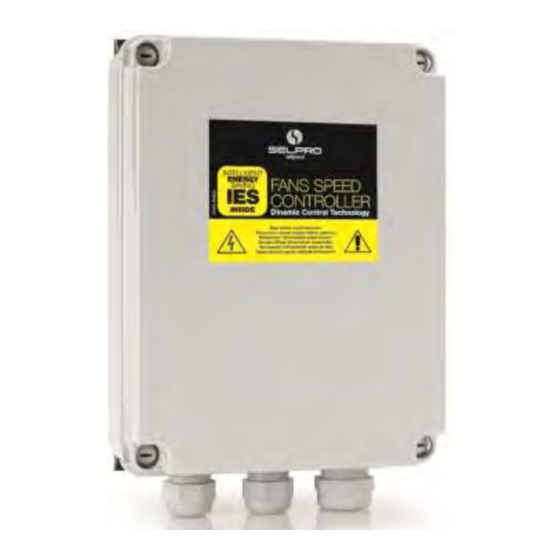
Диагностика частотника S.EL.PRO. MODEL: DRV312-42-5-0-c-s — не крутится FAN.
Чиллер UNIFLAIR 1506 — все вентиляторы (3шт.) второго контура еле вращаются (1 оборот в минуту).
Компрессоры работают, HP=25Бар (R407C)
Частотник — S.EL.PRO. MODEL:DRV312-42-5-0-c-s
https://clck.ru/HV3BHПервый контур работает нормально.
Диагностика частотника второго контура:
L1,L2,L3 = AC380V
Управление =+10v
На выходе частотника — L1,L2,L3 =0V.
По схеме, между частотником и вентилятором есть 2 контактора,
один для одного вентилятора,
второй контактор для двух вентиляторов.
Заключение — неисправен частотник.Правильно ли проведена диагностика — ?
-
07.08.2019, 22:29
#2
Мастер
-
07.08.2019, 23:15
#3
Мастер
Это всё сплошная ошибка. На основании приведённых данных отчебучить такое заключение может только ….стараюсь быть сдержанным, но уже распирает…
RUSSIAнин, ты хоть намекни, что показывают индикаторы? И всё же, кем ты доводишься этому оборудованию? Так и хочется ответить, — вызови мастера, но ты, как бы уже не новичок.
И ещё, соблюдай хоть примерно тематику разделов. Какого переднего хвоста этот вопрос задаётся в «монтаже», или тебе ̶о̶д̶н̶о̶х̶у̶й̶с̶т̶в̶е̶н̶ н̶о̶ …монопенисуально, где и что писать?…Последний раз редактировалось yrtchik; 07.08.2019 в 23:34.
-
08.08.2019, 00:51
#4
Местный
Сообщение от yrtchik
Это всё сплошная ошибка. На основании приведённых данных отчебучить такое заключение может только …
Эта тема не достойна проф раздела, настолько она банальна.Какое напряжение на выходе исправного частотника (фазорезка на симисторах)
без нагрузки — ?
Должен ли светиться зеленый и красный светодиод на частотнике — ?
Цифровой индикатор на частотнике отсутствует.
S.EL.PRO. MODEL:DRV312-42-5-0-c-s
https://clck.ru/HV3BHНе знаю как вставить видеоролик.
Да, я ошибся — вынес приговор двум частотникам S.EL.PRO. MODEL:DRV312-42-5-0-c-s на основании того, что приходящая сила (380V)была, а не было выходящего напряжения 380V для FAN при наличии управления +9V.Вообще-то ошибочно задефектованных частотников было 3.
Его объявил неисправным предшествующий специалист.
-
08.08.2019, 07:55
#5
Мастер
Сообщение от FBT
Эта тема не достойна проф раздела, настолько она банальна.
Эта тема для раздела контроллеров, но уж не «монтаж кондиционеров, ну да бог с ней, а вот частотник и фазорезка,-это два принципиально разных устройства управления…
-
10.08.2019, 07:54
#6
Местный
Сообщение от FBT
Какое напряжение на выходе исправного частотника (фазорезка на симисторах) без нагрузки — ?
Должен ли светиться зеленый и красный светодиод на частотнике — ?
Цифровой индикатор на частотнике отсутствует.
S.EL.PRO. MODEL:DRV312-42-5-0-c-s
https://clck.ru/HV3BHНе знаю как вставить видеоролик.
Да, я ошибся — вынес приговор двум частотникам S.EL.PRO. MODEL:DRV312-42-5-0-c-s на основании того, что приходящая сила (380V)была, а не было выходящего напряжения 380V для FAN при наличии управления +9V.Диагностика S.EL.PRO. MODEL:DRV312-42-5-0-c-s.
При штатной нагрузке FAN ток потребления на входе в частотник — 3А,
светодиоды частотника — зеленый светит, красный не светит.
— Без нагрузки на выходе частотника при напряжении управления U=9V,
на выходе частотника нет напряжения 380V
светится зеленый светодиод,красный — не светит.
— Если вместо вентилятора подключить резисторы 12 КОм, соединенные звездой, то
при напряжении управления U=0V
Зеленый светодиод светит,красный не светит.
Напряжение на выходе частотника AC120V.при напряжении управления U=5V
зеленый светодиод светит, акрасный постоянно мигает.
Напряжение на выходе частотника AC120V— Если вместо вентилятора подключить компрессор (8А)
то светодиоды в частотнике не светятся, нет напряжения на выходе частотника, компрессор не вращается.
-
10.08.2019, 08:22
#7
Местный
Сообщение от FBT
Диагностика S.EL.PRO. MODEL:DRV312-42-5-0-c-s.
При штатной нагрузке FAN ток потребления на входе в частотник — 3А,
светодиоды частотника — зеленый светит, красный не светит.
— Без нагрузки на выходе частотника при напряжении управления U=9V,
на выходе частотника нет напряжения 380V
светится зеленый светодиод,красный — не светит.
— Если вместо вентилятора подключить резисторы 12 КОм, соединенные звездой, то
при напряжении управления U=0V
Зеленый светодиод светит,красный не светит.
Напряжение на выходе частотника AC120V.при напряжении управления U=5V
зеленый светодиод светит, акрасный постоянно мигает.
Напряжение на выходе частотника AC120V— Если вместо вентилятора подключить компрессор (8А)
то светодиоды в частотнике не светятся, нет напряжения на выходе частотника, компрессор не вращается.Аналогичный частотник — CODE VRTMS12BADPL55V1.8if R4
Регулятор скорости вращения трехфазный, серии VRTMT, 230/400В, 50-60 Гц, ном.
ток 12 А, рабочая температура. -25T50, для прямого управления давлением или датчиком ntc, управление 0..10В =, 4..20 мА
https://www.faefagan.it/images/126-vrtmt_en.pdf
https://center-control.ru/product/ko…vrtmt12cptpl55
Крутит этот же компрессор успешно.
-
10.08.2019, 08:46
#8
Мастер
Да не частотник это!, это тиристорный (симисторный) регулятор мощности, как ты правильно сказал-фазорезка. Он предназначен для питания именно вентиляторов. Переведи джампер в режим 0-10в, и перемкни 1-3 клемы, вентилятор должен запуститься. Компрессор может не запуститься из за срабатывания внутренней токовой защиты. Если действующего (под исправной нагрузкой) значения напряжения выходе нет, змерий управляющее на симисторах, если нет-ковыряйся в управлении, там сложного ничего нет. Это старое устройство, я не знаю, сейчас такие применяются или нет…
-
10.08.2019, 08:56
#9
Местный
Сообщение от yrtchik
Да не частотник это!, это тиристорный (симисторный) регулятор мощности, как ты правильно сказал-фазорезка. Он предназначен для питания именно вентиляторов. Переведи джампер в режим 0-10в, и перемкни 1-3 клемы, вентилятор должен запуститься. Компрессор может не запуститься из за срабатывания внутренней токовой защиты. Если действующего (под исправной нагрузкой) значения напряжения выходе нет, змерий управляющее на симисторах, если нет-ковыряйся в управлении, там сложного ничего нет. Это старое устройство, я не знаю, сейчас такие применяются или нет…
Пусть будет «регулятор мощности», он же фазорезка.
Почему два регулятора мощности с номинальным током 12А c одинаковой нагрузкой (компрессор 8А по шильдику) ведут себя по разному — ?Еще один «регулятор мощности» S.EL.PRO. MODEL:DRV312-42-5-0-c-s, установленный в чиллер вел себя по другому — зеленый светодиод не светился, а потом стал светиться.
Я его тоже объявил дохлым.
В течение 2 суток работает нормально, после перепрошивки контроллера чиллера.
Хрень какая-то получается.
3 фазорезки (две из которых абсолютно идентичны по модели и положению переключателей) ведут себя по-разному, при этом все три фазорезки исправны.Реальная схема другая:
На 1 контакт подается +1…10V.
На 3 контакт — минус.
-
10.08.2019, 09:11
#10
Мастер
минус относительно чего???
Сообщение от FBT
Пусть будет
Ну если ты не видишь разницы, тооо….
-
10.08.2019, 09:28
#11
Местный
Попробовал запитать регулятор мощности — S.EL.PRO. MODEL:DRV312-42-5-0-c-s
От частотника VLT 2.2KW (Uвх — АС220V,Uвых — АС220V 3 фазы).
Результат был неожиданным.S.EL.PRO. MODEL:DRV312-42-5-0-c-s:
Uвх:
L1/L2/L3 =220V
Uвых:
T1/T2/T3 = 110V
Без нагрузки на выходе, при управлении 0V.
Cветодиоды красный и зеленый оба светятся еле-еле, не мигают.
-
10.08.2019, 09:39
#12
Местный
Сообщение от yrtchik
минус относительно чего???
Ну если ты не видишь разницы, тооо….
Cигнал плюс 1…10V — первый контакт,
Сигнал минус1…10V — третий контакт.IMHO
Частотник — заполняет синусоиду пакетами 4КГц, регулирует частоту синусоиды.
Фазорезка — режет синус кусками, регулируется мощность.
Перегревается асинхронный двигатель, при минимальной скорости.
Померять ток в этом случае проблематично — синусоида далека от идеала.Разница в количестве букв, кто в теме, тот понимает.
-
10.08.2019, 09:55
#13
Мастер
Оставь пока «частотник» в покое, ты смутно представляешь его работу. У нас наверное разные схемы, щёлкни свою. У меня 1-управление 0+10в, второй GND, третий +10в «питание» для первого относительно GND.
Сообщение от FBT
Попробовал запитать регулятор мощности — S.EL.PRO. MODEL:DRV312-42-5-0-c-s
От частотникаОх-ри-неть! А чё не сварочник? Да вы, батенька…лётчик-теоретик и химик испытатель в одном лице. Теперь я понимаю, зачем вы храните «эпюры напряжений» для каждого подопытного чилера…
-
10.08.2019, 10:04
#14
Местный
Сообщение от yrtchik
Ох-ри-неть! А чё не сварочник? Да вы, батенька…лётчик-теоретик и химик испытатель в одном лице. Теперь я понимаю, зачем вы храните «эпюры напряжений» для каждого подопытного чилера…
И не только.
Я этим частотником успешно кручу инверторный компрессор DAIKIN VRV3.
Хотя менеджер VLT cказал, что этим частотником нельзя крутить BLDC двигатели.
На инверторном компрессоре TOSHIBA успешно засосал масло этим частотником.
-
10.08.2019, 10:07
#15
Местный
Сообщение от yrtchik
…У нас наверное разные схемы, щёлкни свою. У меня 1-управление 0+10в, второй GND, третий +10в «питание» для первого относительно GND…
Да, схема клеммной колодки разная.
2 и 3 наоборот.
-
10.08.2019, 10:16
#16
Мастер
…крутнуть (проверить) можно, я и сам так проверяю бэлдээсы, но только кратковременно проверить, но так чтобы фазорезку к частотнику!!!…эт перебор…
-
21.06.2020, 09:21
#17
Местный
Сообщение от FBT
Уважаемый ref, большое спасибо, что тема и ссылки сохранены.
Пришел в ремонт частотник VRTS20BADPL55 V1.0 R1 c чиллера.
Дефект — нет напряжения на выходе из частотника на вентиляторы.
— Вентиляторы исправны, работают без частотника нормально.
— Между частотником и вентиляторами контакторов нет.
https://docviewer.yandex.ru/view/0/?…%3D%3D&lang=enТеперь есть точка отсчета.
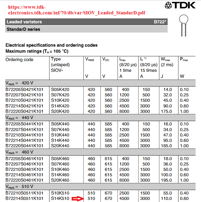
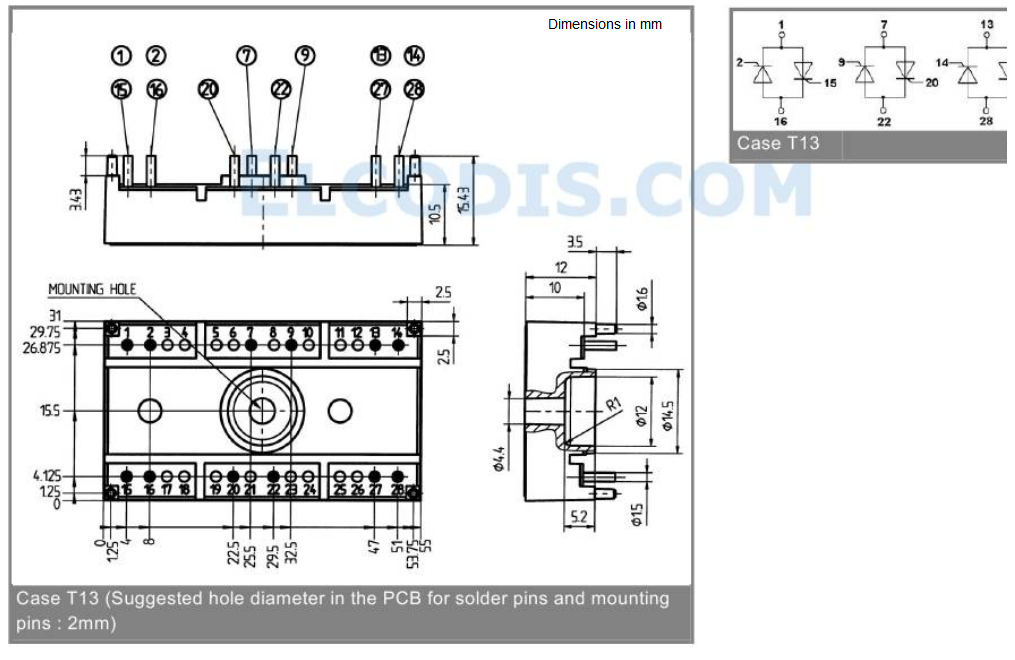
Симисторный модуль SK 45UT12 менялся предшественником, возможно он не штатный.
Варисторы S14K510 — 3 шт. в обвязке симисторного модуля тоже менялись.
-
21.06.2020, 10:05
#18
Местный
Сообщение от FBT
Симисторный модуль SK 45UT12 менялся предшественником, возможно он не штатный.
Варисторы S14K510 — 3 шт. в обвязке симисторного модуля тоже менялись.Установлены варисторы в параллель симисторам, регулирующим напряжение на каждой фазе,
рассчитаны на действующее напряжение VAC 510V:
https://www.tdk-electronics.tdk.com/…d_StandarD.pdfКак умудрились спалить варисторы 510V + 510V (FAN — звезда без нейтрали)
в эл. сети 380V — ?Breezart при таких же токах 20А /380V в ТЭН варисторов в параллель симисторам не ставит:
http://holodforum.ru/showthread.php?t=34234
Наверное, индуктивность роль играет.
-
21.06.2020, 10:40
#19
Местный
Странная ситуация, заменены варисторы и симисторная сборка 20А, а дыма и гари нигде нет.
Такого быть не может.
-
21.06.2020, 10:49
#20
Местный
Сообщение от FBT
…Симисторный модуль SK 45UT12 менялся предшественником, возможно он не штатный…
Поправка.
Модуль SK 45UT12 — это три тиристора с диодами в параллель 45А/1200V .
Т.е. регулировка возможна в диапазоне 50% — 100% мощности вентиляторов.https://elcodis.com/parts/5979416/SK45UT12.html


Похожие темы
-
Ответов: 14
Последнее сообщение: 19.08.2020, 16:39
-
Ответов: 37
Последнее сообщение: 28.07.2019, 23:10
-
Ответов: 6
Последнее сообщение: 19.12.2018, 09:19
-
Ответов: 60
Последнее сообщение: 18.06.2016, 20:58
-
Ответов: 14
Последнее сообщение: 29.05.2014, 10:53
Социальные закладки
Социальные закладки
-
Google

Ваши права

- Вы не можете создавать новые темы
- Вы не можете отвечать в темах
- Вы не можете прикреплять вложения
- Вы не можете редактировать свои сообщения
- BB коды Вкл.
- Смайлы Вкл.
- [IMG] код Вкл.
- [VIDEO] код Вкл.
- HTML код Выкл.
Правила форума
EC-двигатель регулятор / вентилятор — SELPRO
ЕС серия-это полноценный и современный технологический регламент устройства высшую работоспособность EC-двигателями применяется в вентиляторах. Данный системы позволяют модификация системы вентиляции согласно оперативным требованиям энергоэффективности активизировать внутренний потенциал Эко-питания вентиляторов. SELPRO имеет партнерские отношения с ЛЮВЭЙ-группы и EBM-papst, чтобы обеспечить систему регулятора с одного плюс
Есть вопросы?
Вы можете задать их менеджерам наших партнеров прямо сейчас!
Задать вопрос
Written By: Joseph O’Connor

PlayStation 3 Super Slim Fan Replacement PS3 keeps overheating? This guide will walk you through replacing your PS3’s fan. Written By: Joseph O’Connor ifixit CC BY-NC-SA www.ifixit.com Page 1 of 13 INTRODUCTION
More information
Written By: Walter Galan

Xbox 360 CPU Heat Sink Replacement CPU heat sink replacement. Written By: Walter Galan ifixit CC BY-NC-SA www.ifixit.com Page 1 of 27 INTRODUCTION Use this guide to remove the CPU heat sink from your Xbox
More information
Desk/Wall-Mount Rack

Desk/Wall-Mount Rack Patent(s) Pending Installation Instructions Post P/N: 119-1752 119-1781 119-1782 119-4014 Frame P/N: 119-1591 119-1754 119-1755 Kit Contents (2) Frames (4) Posts Assembly Hardware
More information
KN-8828B Upgrade Directions

KN-8828B Upgrade Directions This document outlines the steps to take to update earlier Hottop Bean Roasters to the KN-8828B 2007 by Chang Yue and Hottop USA — All Rights Reserved No part of this document
More information
LP-200 Dummy Load / Wattmeter

LP-200 Dummy Load / Wattmeter Enclosure Retrofit Assembly Instructions March 2009 TelePost Incorporated LP-200 is a trademark of TelePost Inc. Material in this document copyrighted 2009 TelePost Inc. 1
More information
CLEANING THE GALVO MIRRORS

CLEANING THE GALVO MIRRORS Formlabs Customer Support can provide additional information on mirror cleaning and in some cases, provide the customer with the appropriate cleaning supplies. Tools: 2.5mm hex
More information
Series—-SP3600A SHOWER DOOR

Series—-SP3600A SHOWER DOOR INSTALLATION INSTRUCTIONS Please read these instructions carefully to familiarize yourself with the required tools, materials, and installation sequences. The Exploded Diagram
More information
PERSONAL RECORD KEEPING

2 P R O 3 7 0 A s s e m b l y i n s t r u c t i o n s PERSONAL RECORD KEEPING Tip: Record the serial numbers of your Octane Fitness elliptical in the spaces below. This will make it easier for you to obtain
More information
Sea Doo Spark Engine Access Kit

Sea Doo Spark Engine Access Kit PART# — RS4-130-EAK APPLICATION(S): Sea Doo Spark. 2up & 3up Models. We strongly recommend the use of a service manual to familiarize yourself with the various components
More information
EDGE2 DUAL MONITOR ARM

EDGE2 DUAL MONITOR ARM EDGE2 Rev A 2/17 Model EDGE2-SLV Model EDGE2-BLK Model EDGE2-WHT ASSEMBLY AND ADJUSTMENT EDGE2 DUAL MONITOR ARM PARTS AND TOOLS PLEASE REVIEW these instructions before beginning
More information
Harmony Remote Repair

Harmony Remote Repair harmonyremoterepair.com How to install your new Harmony One Front Cover/Touch Screen Important! Before you begin working on your Harmony One, you must discharge any static electricity
More information
Installation Instructions

READ BEFORE INSTALLING UNIT INSTALLATION WARNINGS AND CAUTION Carefully read the installation manual before beginning. Follow each step as shown. Observe all local, state, and national electrical codes
More information
For additional assistance call

The following pages will help guide you through the process of assembling your new 48 custom prize wheel. Choose an assembly area with plenty of room to lay your pieces on the floor and also a bench or
More information
ASSEMBLY AND ADJUSTMENT

EDGE MONITOR ARM EDGE Rev A 2/17 Model EDGE-SLV Model EDGE-BLK Model EDGE-WHT ASSEMBLY AND ADJUSTMENT EDGE MONITOR ARM PARTS AND TOOLS PLEASE REVIEW these instructions before beginning the assembly and
More information
Installing the Onyx Heated Bed

Installing the Onyx Heated Bed This short supplement will guide you through replacing the Phebe I heated bed on your Rostock MAX with the new Onyx heated bed. Your Onyx upgrade kit should include the following
More information
DO NOT PULL ON THE SHEATH.

Removing and Replacing the Head Cover To remove and replace the head cover you will need the following tools: #2 Phillips screwdriver (magnetic tip preferred) Removing the Head Cover 1. Ready the machine
More information
Sony BDV-NF620 Teardown

This is the teardown on a amp/bd player/media receiver that looks like a PlayStation 3 Super Slim Written By: Federico Barutto ifixit CC BY-NC-SA www.ifixit.com Page 1 of 18 TOOLS: Phillips #2 Screwdriver
More information
Installation Instructions

Installation Instructions READ BEFORE INSTALLING UNIT For Slider Casement Air Conditioners INSTALLATION WARNINGS AND CAUTION Carefully read the installation manual before beginning. Follow each step as
More information
installation instructions

installation instructions Easi-Plan WC Frame 820mm with Dual Flush Cistern ref: EPWC-05-1005 Easi-Plan WC Frame 980mm with Dual Flush Cistern ref: EPWC-05-1505 EASI-PLAN installation instructions Parts
More information
INSTALLATION INSTRUCTIONS

INSTALLATION INSTRUCTIONS Universal Low Profile Tilt Mount Model: U.S. Toll Free: 1-866-752-6271 Outside N. America: 1-503-748-5799 E-mail: ts@planar.com FRANCE Phone: +33 5 6378 3810 E-mail: emeats@planar.com
More information
ABM International, Inc.

ABM International, Inc. Lightning Stitch required 1 1.0: Parts List head and motor assembly (Qty. 1) Reel stand (Qty. 1) Needle bar frame clamp (Qty. 1) Motor drive (Qty. 1) 2 Cable harness with bracket
More information
PERSONAL RECORD KEEPING

Q47e/Q47ce 2 Q 4 7 e / Q 4 7 c e A s s e m b l y i n s t r u c t i o n s PERSONAL RECORD KEEPING IMPORTANT: Record the serial numbers of your Octane Fitness elliptical in the spaces below. This will make
More information
Explorer Wiring Kit (assembled)
")
Explorer Wiring Kit (assembled) For Vintage, Firestorm & Standard Series Please Read All Instructions Before Beginning. Tools you will need: Soldering Iron (35 watt preferably) Solder Wet Sponge Wire Clippers
More information
ASSEMBLY AND ADJUSTMENT

EPPA MONITOR ARM EPPA Rev A 10/17 Model EPPA-XXX ASSEMBLY AND ADJUSTMENT EPPA MONITOR ARM PARTS AND TOOLS PLEASE REVIEW these instructions before beginning the assembly and adjustment procedures. Check
More information
Removing and Replacing the Y-truck

Service Documentation Removing and Replacing the Y-truck To remove and replace the Y-truck you will need the following tools: 4mm Allen wrench 12mm stamped flat wrench #2 Phillips screwdriver (magnetic
More information
SUT-1000CLC ASSEMBLY REQUIREMENTS

SUT-1000CLC Torque wrench, carpenters square, wire cutters, Phillips screwdriver, 7/16, 9/16, and 3/4 combination wrenches, ratchet, 9/16, 3/4, 13/16, and 7/8 sockets. ASSEMBLY REQUIREMENTS *Torque all
More information
iphone 4S Dismantling Instructions

iphone 4S Dismantling Instructions These instructions will show you how to open the iphone to replace the digitizer, LCD screen and other internal parts. Opening your iphone will void your warrantee, and
More information
Assembly Instructions

InTandem Table System November 20 InTandem Table System — Worksurface #4 x/» 4 wood screw power beam Tools Provided T-0 Extended Torx Driver T-25 Torx Driver Additional Tools Required Soft protective
More information
Installation Instructions

For Medium (15-18.5K) + Heavy duty (-8.5K) Air Conditioner READ BEFORE INSTALLING UNIT To avoid risk of personal injury, property damage, or product damage due to the weight of this device and sharp edges
More information
Termination Procedure

Connector Piece Parts Contact/Connector Head Twist On Nut MX MX Boot Procedure Chart Procedure Tool Required Tool Part Number Cable Preparation & Fiber Cleaning Jacket Stripper 86710-0004 Cable Preparation
More information
Seamed Undermount Bowls

CUTOUT TEMPLATES MAKING CUTOUT TEMPLATES 7.1 CUTOUT TEMPLATES The use of an accurate template is one of the most essential elements to the successful completion of a cutout in Corian. For the completion
More information
PERSONAL RECORD KEEPING

PRO3700 2 P R O 3 7 0 0 A s s e m b l y i n s t r u c t i o n s PERSONAL RECORD KEEPING Tip: Record the serial numbers of your Octane Fitness elliptical in the spaces below. This will make it easier for
More information
SuperTrack Parts List

SuperTrack Parts List [indicates number for 6 lane tracks] SuperTrack Installation Instructions www.supertimer.com 1-800-654-2088 1 Track Instruction Manual (this booklet) 2 Start sections [3] Start Gate
More information
Written By: Chad Facciolo

HTC One Mini 2 Charging Port Replacement These instructions will show you how to replace your charging port. Written By: Chad Facciolo ifixit CC BY-NC-SA www.ifixit.com Page 1 of 11 INTRODUCTION The charging
More information
Quickstart
This is a
secure
Multilevel Switch
for
.
To run this device please connect it to your mains power supply.
Important safety information
Please read this manual carefully. Failure to follow the recommendations in this manual may be dangerous or may violate the law.
The manufacturer, importer, distributor and seller shall not be liable for any loss or damage resulting from failure to comply with the instructions in this manual or any other material.
Use this equipment only for its intended purpose. Follow the disposal instructions.
Do not dispose of electronic equipment or batteries in a fire or near open heat sources.
What is Z-Wave?
Z-Wave is the international wireless protocol for communication in the Smart Home. This
device is suited for use in the region mentioned in the Quickstart section.

Z-Wave ensures a reliable communication by reconfirming every message (two-way
communication) and every mains powered node can act as a repeater for other nodes
(meshed network) in case the receiver is not in direct wireless range of the
transmitter.
This device and every other certified Z-Wave device can be used together with any other
certified Z-Wave device regardless of brand and origin as long as both are suited for the
same frequency range.
If a device supports secure communication it will communicate with other devices
secure as long as this device provides the same or a higher level of security.
Otherwise it will automatically turn into a lower level of security to maintain
backward compatibility.
For more information about Z-Wave technology, devices, white papers etc. please refer
to www.z-wave.info.
Product Description
4 Speed Fan controller 120VAC.Compatible with pull chain ceiling fans without electronic control.White paddle and vanishing LEDs.Color change kits are available to change to Light Almond, Ivory, Black, Brown, Gray.
Prepare for Installation / Reset
Please read the user manual before installing the product.
In order to include (add) a Z-Wave device to a network it must be in factory default
state. Please make sure to reset the device into factory default. You can do this by
performing an Exclusion operation as described below in the manual. Every Z-Wave
controller is able to perform this operation however it is recommended to use the primary
controller of the previous network to make sure the very device is excluded properly
from this network.
Safety Warning for Mains Powered Devices
ATTENTION: only authorized technicians under consideration of the country-specific
installation guidelines/norms may do works with mains power. Prior to the assembly of
the product, the voltage network has to be switched off and ensured against re-switching.
Inclusion/Exclusion
On factory default the device does not belong to any Z-Wave network. The device needs
to be added to an existing wireless network to communicate with the devices of this network.
This process is called Inclusion.
Devices can also be removed from a network. This process is called Exclusion.
Both processes are initiated by the primary controller of the Z-Wave network. This
controller is turned into exclusion respective inclusion mode. Inclusion and Exclusion is
then performed doing a special manual action right on the device.
Quick trouble shooting
Here are a few hints for network installation if things dont work as expected.
- Make sure a device is in factory reset state before including. In doubt exclude before include.
- If inclusion still fails, check if both devices use the same frequency.
- Remove all dead devices from associations. Otherwise you will see severe delays.
- Never use sleeping battery devices without a central controller.
- Dont poll FLIRS devices.
- Make sure to have enough mains powered device to benefit from the meshing
Association – one device controls an other device
Z-Wave devices control other Z-Wave devices. The relationship between one device
controlling another device is called association. In order to control a different
device, the controlling device needs to maintain a list of devices that will receive
controlling commands. These lists are called association groups and they are always
related to certain events (e.g. button pressed, sensor triggers, …). In case
the event happens all devices stored in the respective association group will
receive the same wireless command wireless command, typically a ‘Basic Set’ Command.
Association Groups:
Group NumberMaximum NodesDescription
Configuration Parameters
Z-Wave products are supposed to work out of the box after inclusion, however
certain configuration can adapt the function better to user needs or unlock further
enhanced features.
IMPORTANT: Controllers may only allow configuring
signed values. In order to set values in the range 128 … 255 the value sent in
the application shall be the desired value minus 256. For example: To set a
parameter to 200 it may be needed to set a value of 200 minus 256 = minus 56.
In case of a two byte value the same logic applies: Values greater than 32768 may
needed to be given as negative values too.
Parameter 3: Min Level
Minimum Fan Speed level allowed
Size: 1 Byte, Default Value: 10
SettingDescription
| 0 – 99 | Minimum Speed Level |
Parameter 4: Max Level
Maximum Fan Speed level allowed
Size: 1 Byte, Default Value: 99
SettingDescription
Parameter 5: Preset Level
Preset Level for On
Size: 1 Byte, Default Value: 0
SettingDescription
| 0 | Memory Dim – Last speed |
| 1 – 99 | Level |
Parameter 6: Ind Timeout
LED Dim Level Indicator Timeout
Size: 1 Byte, Default Value: 3
SettingDescription
| 0 | Indicator Off |
| 1 – 254 | Level Indicator Timeout (seconds) |
| 255 | Level Indicator Always On |
Parameter 7: Locator Status
Locator LED Status
Size: 1 Byte, Default Value: 255
SettingDescription
| 0 | LED Off |
| 254 | Status Mode |
| 255 | Locater Mode |
Technical Data
| Hardware Platform | ZGM130 |
| Device Type | Multilevel Switch |
| Generic Device Class | Switch Binary |
| Specific Device Class | Binary Power Switch |
| Network Operation | Always On Slave |
| Firmware Version | HW: 1 FW: 1.07 |
| Z-Wave Version | 7.12.2 |
| Certification ID | ZC12-20040040 |
| Z-Wave Product Id | 0x001D.0x0038.0x0002 |
| Neutral Wire Required | ok |
| Firmware Updatable | Updatable by Consumer by RF |
| Z-Wave Scene Type | Scene |
| Security V2 | S2_UNAUTHENTICATED ,S2_AUTHENTICATED |
| Frequency | XXfrequency |
| Maximum transmission power | XXantenna |
Supported Command Classes
- Association Grp Info V3
- Association V2
- Basic V2
- Configuration V4
- Device Reset Locally
- Firmware Update Md V5
- Indicator V3
- Manufacturer Specific V2
- Multi Channel Association V3
- Powerlevel
- Scene Activation
- Scene Actuator Conf
- Security
- Security 2
- Supervision
- Switch Multilevel V4
- Transport Service V2
- Version V3
- Zwaveplus Info V2
Explanation of Z-Wave specific terms
- Controller — is a Z-Wave device with capabilities to manage the network.
Controllers are typically Gateways,Remote Controls or battery operated wall controllers. - Slave — is a Z-Wave device without capabilities to manage the network.
Slaves can be sensors, actuators and even remote controls. - Primary Controller — is the central organizer of the network. It must be
a controller. There can be only one primary controller in a Z-Wave network. - Inclusion — is the process of adding new Z-Wave devices into a network.
- Exclusion — is the process of removing Z-Wave devices from the network.
- Association — is a control relationship between a controlling device and
a controlled device. - Wakeup Notification — is a special wireless message issued by a Z-Wave
device to announces that is able to communicate. - Node Information Frame — is a special wireless message issued by a
Z-Wave device to announce its capabilities and functions.